

Panasonic CS-D34DTQ, CU-D34DBQ7, CS-D43DTQ, CU-D43DBQ7, CS-D50DTQ Service Manual
...
© 2006 Panasonic HA Air-Conditioning (M) Sdn Bhd
(11969-T). All rights reserved. Unauthorized copying
and distribution is a violation of law.
Order No. MAC0603021C3
Air Conditioner
CS-D34DTQ CU-D34DBQ7
CS-D43DTQ CU-D43DBQ7
CS-D50DTQ CU-D50DBQ7
TABLE OF CONTENTS
PAGE PAGE
1 Service Information---------------------------------------------- 3
1.1. Example of trouble at test operation------------------ 3
1.2. Caution of test operation--------------------------------- 3
1.3. Caution during automatic address setting----------- 3
1.4. Operation range-------------------------------------------- 4
2Features------------------------------------------------------------- 5
2.1. Ceiling Type------------------------------------------------- 5
2.2. Outdoor Unit ----------------------------------------------- 5
2.3. Wired Remote Control------------------------------------ 7
2.4. Wireless Remote Control --------------------------------7
2.5. Group Control Equipment--------------------------------8
3 Product Specification -------------------------------------------9
3.1. CS-D34DTQ CU-D34DBQ7 (50Hz)-------------------9
3.2. CS-D34DTQ CU-D34DBQ7 (60Hz)----------------- 10
3.3. CS-D43DTQ CU-D43DBQ7 (50Hz)----------------- 11
3.4. CS-D43DTQ CU-D43DBQ7 (60Hz)----------------- 12
3.5. CS-D50DTQ CU-D50DBQ7 (50Hz)----------------- 13
3.6. CS-D50DTQ CU-D50DBQ7 (60Hz)----------------- 14

2
3.7. Safety Devices--------------------------------------------15
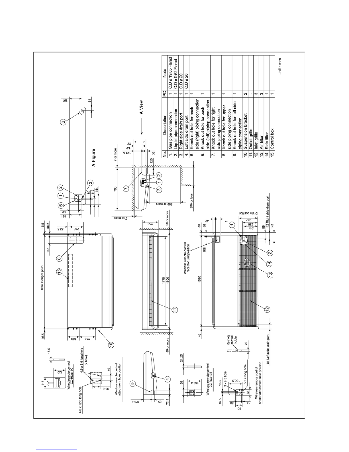
4 Dimensions -------------------------------------------------------16
4.1. Indoor Unit -------------------------------------------------16
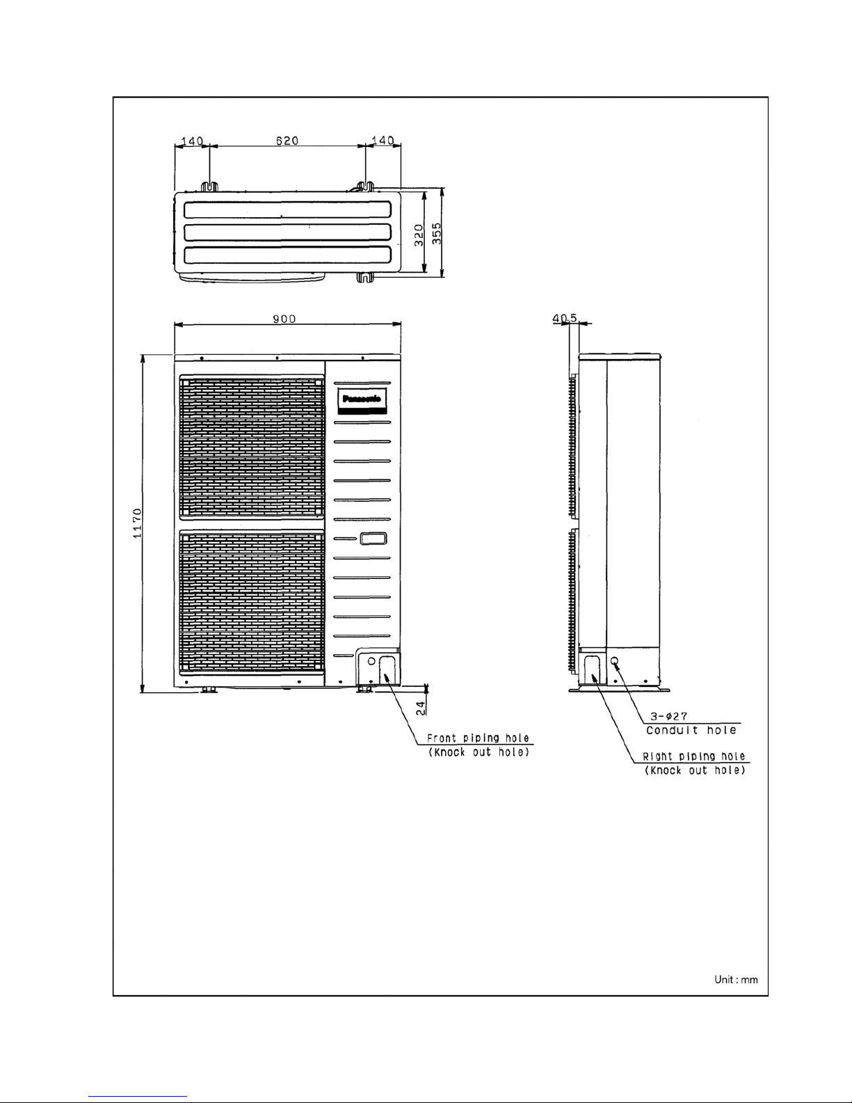
4.2. Outdoor Unit-----------------------------------------------17
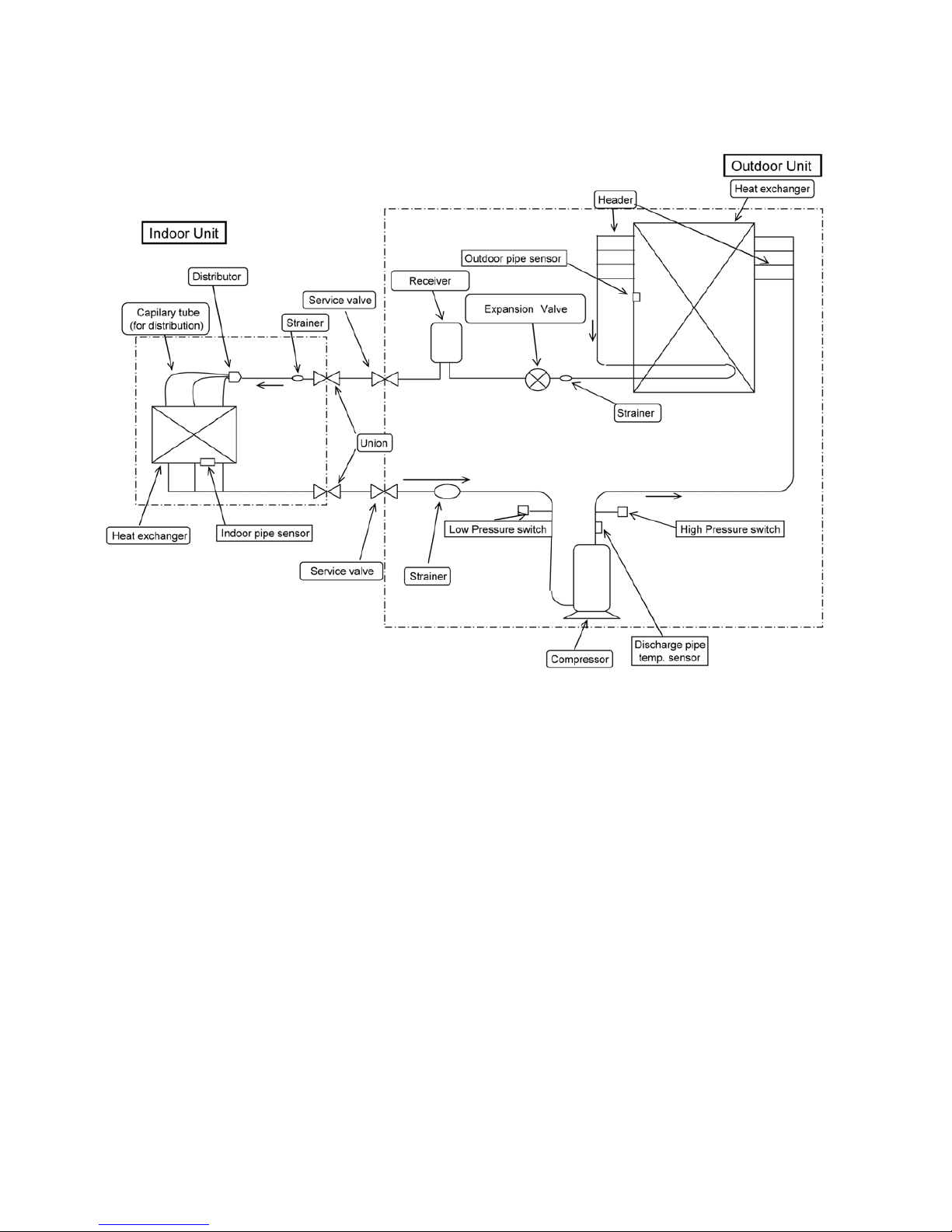
5 Refrigeration Cycle---------------------------------------------18
5.1. CS-D34DTQ CU-D34DBQ7---------------------------18
5.2. CS-D43DTQ CU-D43DBQ7 CS-D50DTQ CUD50DBQ7 --------------------------------------------------19
6 Block Diagram ---------------------------------------------------20
6.1. CS-D34DTQ CS-D43DTQ CS-D50DTQ ----------- 20
6.2. CU-D34DBQ7 CU-D43DBQ7 CU-D50DBQ7 ---- 20
7 Wiring Diagram --------------------------------------------------21
7.1. CS-D34DTQ CS-D43DTQ CS-D50DTQ ---------- 21
7.2. CU-D34DBQ7 CU-D43DBQ7 CU-D50DBQ7 ----- 22
8 Operation Instructions ----------------------------------------23
8.1. Wired Remote Control (Optional part)-------------- 23
8.2. Remote Control - Display ------------------------------24
8.3. Remote Control - Panel --------------------------------25
8.4. How to set remote control day and time------------26
8.5. How To Select The Timer ------------------------------26
8.6. Daily Timer Setting---------------------------------------27
8.7. Weekly Timer Setting------------------------------------ 28
8.8. Wireless Remote Control (Optional part)-----------30
9 Operation Details------------------------------------------------31
9.1. Cooling Operation----------------------------------------31
9.2. Soft Dry Operation---------------------------------------31
9.3. Auto Operation--------------------------------------------31
9.4. Fan Operation---------------------------------------------31
9.5. Operation Control ----------------------------------------32
9.6. Test Run (Forced Cooling mode) --------------------34
9.7. Pump down------------------------------------------------35
10 Installation Instruction ----------------------------------------36
10.1. Pipe length-------------------------------------------------36
10.2. Refrigerant additional charge -------------------------37
10.3. Position of the centre gravity--------------------------37
10.4. Indoor unit installation-----------------------------------38
10.5. Outdoor unit installation ------------------------------- 48
10.6. Wired remote control installation---------------------58
10.7. Wireless remote control installation manual-------65
10.8. Twin Operation--------------------------------------------72
11 Troubleshooting Guide----------------------------------------73
11.1. For standard installation--------------------------------73
11.2. During twin operation------------------------------------75
11.3. During group control operation -----------------------77
11.4. Test operation and self-diagnosis --------------------77
11 .5. Emergency operation -----------------------------------81
11.6. Self-diagnosis error code table ----------------------- 83
12 Technical Data----------------------------------------------------84
12.1. Cooling capacity performance data------------------84
12.2. Capacity and power consumption--------------------87
12.3. Reaching distance ---------------------------------------93
12.4. Sound measuring point---------------------------------96
12.5. Sound data-------------------------------------------------97
12.6. Fan performance--------------------------------------- 100
12.7. Discharge and suction pressure-------------------- 102
12.8. Operating characteristics----------------------------- 102
13 Exploded View (Indoor Unit) ------------------------------ 103
13.1. CS-D34DTQ CS-D43DTQ CS-D50DTQ --------- 103
13.2. CS-D34DTQ CS-D43DTQ CS-D50DTQ --------- 104
13.3. CS-D34DTQ CS-D43DTQ CS-D50DTQ --------- 105
14 Replacement Part List (Indoor Unit)-------------------- 106
15 Exploded View (Outdoor Unit) ----------------------------108
15.1. CU-D34DBQ7 CU-D43DBQ7 CU-D50DBQ7----108
15.2. CU-D34DBQ7 CU-D43DBQ7 CU-D50DBQ7----109
15.3. CU-D34DBQ7 CU-D43DBQ7 CU-D50DBQ7----110
16 Replacement Part List (Outdoor Unit) ------------------ 111
16.1. CU-D34DBQ7 CU-D43DBQ7 CU-D50DBQ7---- 111
17 Print Pattern-----------------------------------------------------112
17.1. Indoor Unit Printed (Main)----------------------------112
17.2. Indoor Unit Printed (Indicator)-----------------------113
17.3. Outdoor Unit (Main) ------------------------------------113

3
1 Service Information
The new Cassette / New Outdoor models are possible to have address setting for twin control or group control by automatic when main power supply is switched on.
(Manual address setting is also possible by using Dip switch on Indoor unit P.C. board.) Howeve r, this address setting is only
possible when made proper wiring connection and also Indoor unit should be original virgin unit.
1.1. Example of trouble at test operation
If found out as following phenomenon at test operation on site, it may have possibility of wrong address setting.
Therefore, please ensure of the address setting.
1. LCD display of wired remote control had not illuminate although the main power supply switch is ‘on’.
2. LCD display had indicated as normal illumination when power supply switch is ‘on’, however outdoor unit cannot be operated.
(But, it is necessary to take 3 to 5 minutes for outdoor unit to start from the timing of remote control ON/OFF switch is ‘on’.)
3. P.C. board had memorized wrong setting information.
a. If main power supply is switched ‘on’ with the wrong connection.
b. When changing the connection or combination of units due to re-installation etc.
• When changing the system from group control to normal one to one system.
• When making the replacement of units as master and slave etc.
1.2. Caution of test operation
Do not touch the remote control switch and do not change any wirings for one minute when the main power supply switch is ‘on’.
(Because the unit is having automatic address setting during the first one minute.)
1.3. Caution during automatic address setting
When main power supply switch is ‘on’, the P.C. board will automatically memorize the connecting system.
Consequently, when initial power supply is ‘on’, there will not be interchangeability of units even of the same type and same capacity unit. Therefore unable to connect the unit to another system.
Notice of Address setting for NEW Cassette / NEW Outdoor Unit.
4
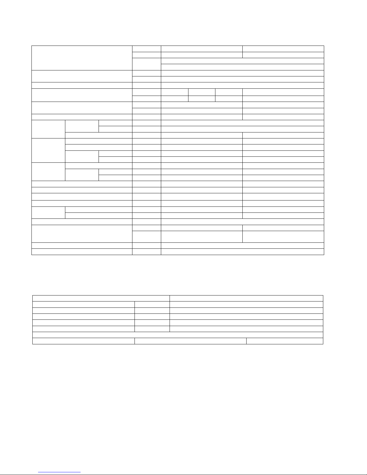
1.4. Operation range
1.4.1. Power Supply
The applicable voltage range for each unit is given in the following table. The working voltage among the three phases must be balanced within a 3% deviation from each voltage at the compressor terminals. The starting voltage must be higher than 85% of the
rated voltage.
1.4.2. Indoor and Outdoor Temperature
• Model 50Hz / 60Hz CU-D34DBQ7 CU-D43DBQ7 CU-D50DBQ7
MODEL Unit Main Power Applicable Voltage
CU- Phase, Volts Hz Max. Min.
D34DBQ7 3 ~ 220 50/60 242 198
D43DBQ7 3 ~ 220 50/60 242 198
D50DBQ7 3 ~ 220 50/60 242 198
Operating Hz Indoor Temp. (D.B./W.B.) (°C) Outdoor Temp. (D.B./W.B.) (°C)
Max. Min. Max. Min.
Cooling 50/60 32/23 21/15 43/- 5/-
5
2 Features
2.1. Ceiling Type
2.1.1. Easier Maintenance and Cleaning
• Anti-Mould Long Life Air Filter.
• 3-Direction Pipe Lead-Out.
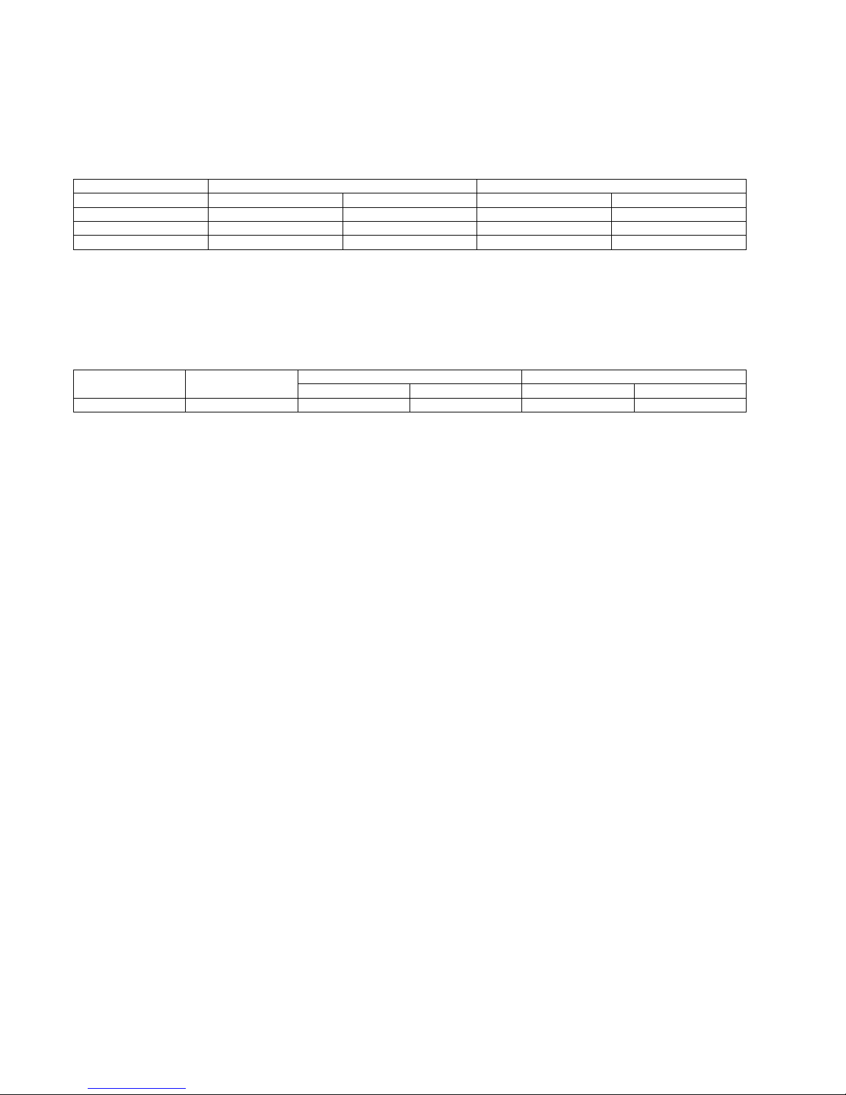
2.1.2. Wide Air Discharge, Comfortable Control
• Wide-Angle Airflow — 100 Degrees Horizontal.
• Auto Swing Louver.
2.2. Outdoor Unit
2.2.1. Flexible Installation in Smaller Spaces
• Spacing-saving outdoor unit with the improvement of the outdoor unit fan makes it possible to install the outdoor unit into a
smaller space where the conventional model cannot be installed.

6
• Long Pipe design with maximum piping length of 40m (50Hz), 50m (60Hz).
• Flexible 4-way piping.
• Centralized Drain Method gathered multiple outdoor unit’s drain pipes into a single drain pipe to make installation easier an d
also improve appearance.
• Side-by-Side Continuous Installation is possible eve n outdoor units with different capacities.
2.2.2. Quiet, Efficient Design
• A host of silencing technologies achieves super-quiet operation.
• The Noise-Suppressing Winglet Fan is a result of new research into vane design theory. The unique curved shaped suppressed
the generation of vortexes, thus reduces air flows noise.
• Operating efficiency is improved and energy consumption reduced.
2.2.3. Low Ambient Cooling Operation
• The unit can set for cooling even when the outdoor temperature drops to 5°C. This is ideal for locations that require cooling even
in winter.
7
2.3. Wired Remote Control
1. The new design includes an easily-visible red pilot l amp. The power can be turned on and off at a single touch, without opening the cover .
2. Has a build-in thermistor, allowing indoor temperature detection in accordance with indoor conditions by switching with mai n
unit thermistor.
3. Twin non-polar wires make installation work easy. (10 m cable supplied as accessory.)
2.4. Wireless Remote Control
1. New design with compact size. (Operation range within approximately 8 m.)
2. Built-in timer with OFF/ON timer setting (within 24 hours)
NOTE: Both of the above remote control is packed separately from the indoor unit.
Wired Wireless
CZ-RD513C CZ-RL013T
8
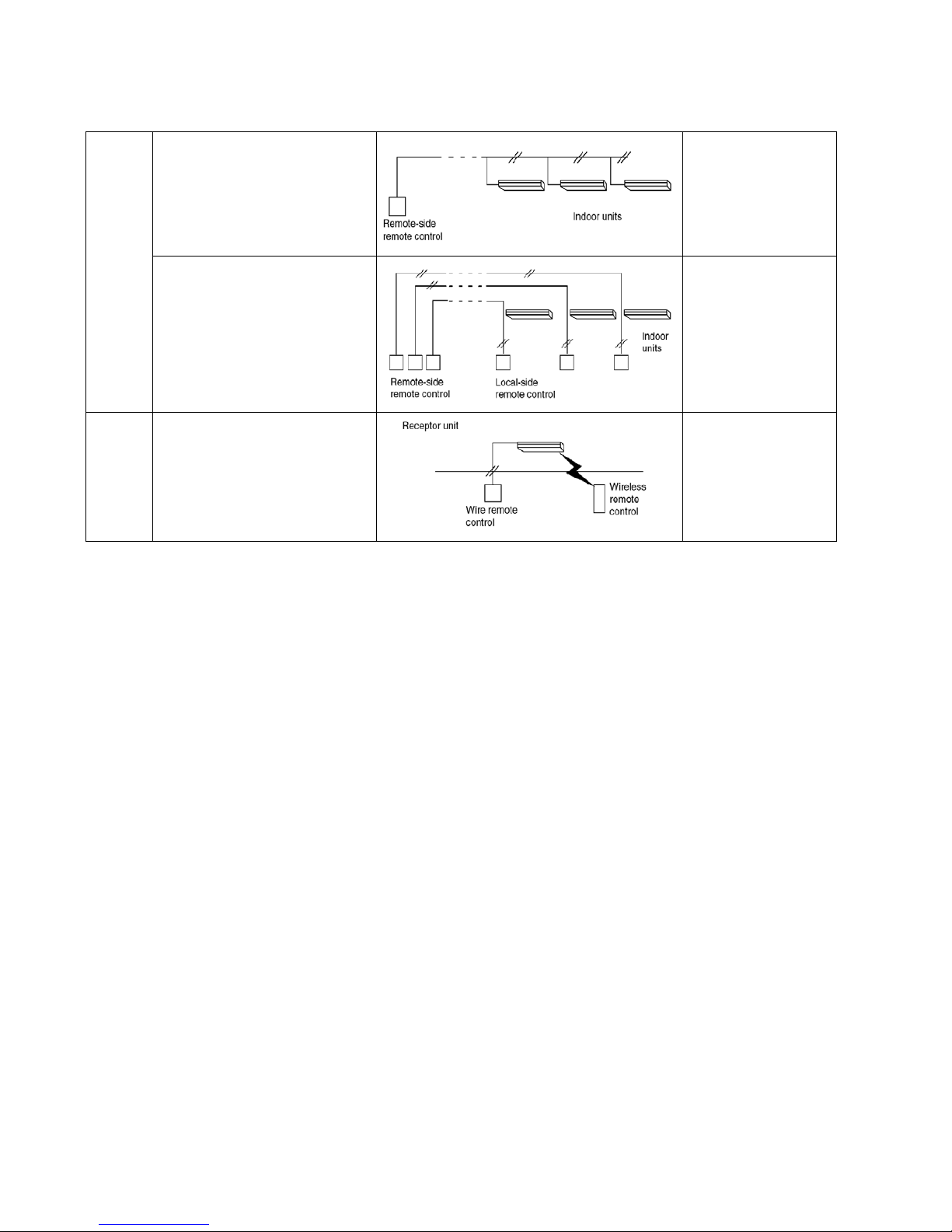
2.5. Group Control Equipment
Wired
Remote
Control
Group control by one remote control
• All air conditioner units are controlled
as a whole by remote control.
• All indoor units operate in the same
mode.
• A maximum of 16 units can be connected together (sequential starting)
[Remote side]
• Optional wired remote
control CZ-RD513C
[Local side]
Not needed
Twin remote control separate control
• Each indoor unit can be operated by
either one of the two remote control.
• Apart from timer setting time, displays
for two remote control are identical.
• Last button pressed has priority (main
or slave is set at remote control unit).
[Remote side]
• Optional wired remote
control
[Local side]
• Optional wired remote
control CZ-RD513C
Common
Control
Common control / group
• Operation is possible using either
wired or wireless remote control unit.
• Last button pressed has priority.
• Optional wired remote
control and wireless
remote control
Wired CZ-RD513C
Wireless CZ-RL013T

9
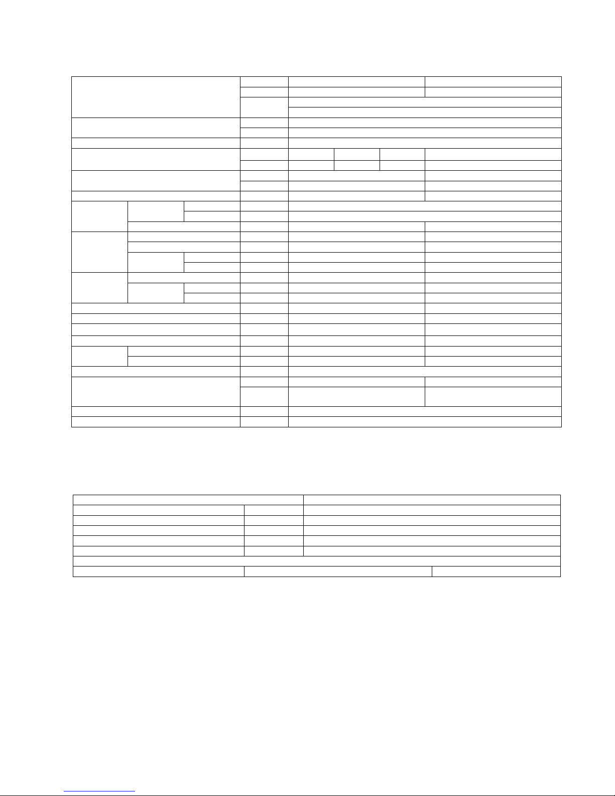
3 Product Specification
3.1. CS-D34DTQ CU-D34DBQ7 (50Hz)
1. Cooling capacities are based on indoor temperature of 27°C D.B. (80.6°F D.B.), 19.0°C W.B. (66.2°F W.B.) and outdoor air
temperature of 35°C D.B. (95°F D.B.), 24°C W.B. (75.2°F W.B.)
ELECTRICAL DATA (50 Hz)
Indoor Unit Outdoor Unit
ITEM / MODEL Main Body CS-D34DTQ CU-D34DBQ7
Remote CZ-RD513C (Wired)
Control CZ-RL013T (Wireless)
Cooling Capacity kW 10.0
BTU/h 34,100
Refrigerant Charge-less m 20
Standard Air Volume for High,
m
3
/min
Hi 30.0 Me 27.5 Lo 24.8 100.0
Medium and Low Speed cfm 1059 972 876 3531
Outside Dimension (H × W × D) mm 250 × 1600 × 700 1170 × 900 × 320
inch 9-27/32 × 62-31/32 × 27-9/16 46-1/16 × 35-7/16 × 12-19/32
Net Weight kg (lbs) 43 (94) 83 (182)
Piping Refrigerant Gas mm (inch) O.D Ø 19.05 (3/4) Flared Type
Connection Liquid mm (inch) O.D Ø 9.52 (3/8) Flared Type
Drain O.D Ø 20 I.D Ø 20
Compressor Type, Number of Set — Hermetic, 1
Starting Method — Permanent Split Capacitor
Motor Type — 2-pole 1 phase brushless motor
Rated Output kW — 3.0
Fan Type, Number of Set Sirocco fan-1 P ropeller fan-1
Motor Type 4-pole single phase induction motor 6-pole single phase induction motor
Rated Output kW 0.07 0.07 × 2
Air-heat Exchanger (Row × Stage × FPI) Louver-fin type (2 × 18 × 14) Corrugate-fin type (1 × 44 × 21)
Refrigerant Control — Expansion Valve
Refrigerant Oil (Charged)
cm
3
— 1400
Refrigerant (Charged) R22 kg (oz) — 1.90 (67.0)
Running Control Switch Wireless or Wired Remote Control —
Adjustment Room Temperature Thermostat —
Safety Devices Internal protector for compressor
Noise Level dB (A) Hi 46 Lo 42 Hi 53
Power Level
dB
63/59 67/-
Moisture Removal L/h (Pt/h) 6.0 (12.5)
EER W/W 2.56
ITEM / MODEL Condition by ISO5151
Volts V 220
Phase Three
Running Current A 12.8
Starting Current A 115
Power Factor % 80
*Power Factor means total figure of compressor, indoor fan motor and outdoor fan motor.
Panasonic Power Source AC, 3 ~ 220V, 50Hz
10
3.2. CS-D34DTQ CU-D34DBQ7 (60Hz)
1. Cooling capacities are based on indoor temperature of 27°C D.B. (80.6°F D.B.), 19.0°C W.B. (66.2°F W.B.) and outdoor air
temperature of 35°C D.B. (95°F D.B.), 24°C W.B. (75.2°F W.B.)
ELECTRICAL DATA (60 Hz)
Indoor Unit Outdoor Unit
ITEM / MODEL Main Body CS-D34DTQ CU-D34DBQ7
Remote CZ-RD513C (Wired)
Control CZ-RL013T (Wireless)
Cooling Capacity kW 10.8
BTU/h 36,800
Refrigerant Charges-less m 30
Standard Air Volume for High,
m
3
/min
Hi 30.0 Me 26.8 Lo 23.5 103.0
Medium and Low Speed cfm 1059 945 830 3637
Outside Dimension (H × W × D) mm 250 × 1600 × 700 1170 × 900 × 320
inch 9-27/32 × 62-31/32 × 27-9/16 46-1/16 × 35-7/16 × 12-19/32
Net Weight kg (lbs) 33 (73) 61 (134)
Piping Refrigerant Gas mm (inch) O.D Ø 19.05 (3/4) Flared Type
Connection Liquid mm (inch) O.D Ø 9.52 (3/8) Flared Type
Drain O.D Ø 20 I.D Ø 20 × 1
Compressor Type, Number of Set — Hermetic, 1
Starting Method — Permanent Split Capacitor
Motor Type — 2-pole 1 phase brushless motor
Rated Output kW — 3.0
Fan Type, Number of Set Sirocco fan-1 Propeller fan-1
Motor Type 4-pole single phase induction motor 6-pole single phase induction motor
Rated Output kW 0.07 0.07 × 2
Air-heat Exchanger (Row × Stage × FPI) Louver-fin type (2 × 18 × 14) Corrugate-fin type (1 × 44 × 21)
Refrigerant Control — Expansion Valve
Refrigerant Oil (Charged)
cm
3
— 1400
Refrigerant (Charged) R22 kg (oz) — 1.90 (67.0)
Running Control Switch Wireless or Wired Remote Control —
Adjustment Room Temperature Thermostat —
Safety Devices Internal protector for compressor
Noise Level dB (A) Hi 46 Lo 42 Hi 54
Power Level
dB
63/59 68/-
Moisture Removal L/h (Pt/h) 6.6 (13.8)
EER W/W 2.45
ITEM / MODEL Condition by ISO5151
Volts V 220
Phase Three
Running Current A 12.8
Starting Current A 105
Power Factor % 90
*Power Factor means total figure of compressor, indoor fan motor and outdoor fan motor.
Panasonic Power Source AC, 3 ~ 220V, 60Hz

11
3.3. CS-D43DTQ CU-D43DBQ7 (50Hz)
1. Cooling capacities are based on indoor temperature of 27°C D.B. (80.6°F D.B.), 19.0°C W.B. (66.2°F W.B.) and outdoor air
temperature of 35°C D.B. (95°F D.B.), 24°C W.B. (75.2°F W.B.)
ELECTRICAL DATA (50 Hz)
Indoor Unit Outdoor Unit
ITEM / MODEL Main Body CS-D43DTQ CU-D43DBQ7
Remote CZ-RD513C (Wired)
Control CZ-RL013T (Wireless)
Cooling Capacity kW 12.50
BTU/h 42,700
Refrigerant Charge-less m 20
Standard Air Volume for High,
m
3
/min
Hi 29.0 Me 26.7 Lo 24.1 100.0
Medium and Low Speed cfm 1024 943 849 3531
Outside Dimension (H × W × D) mm 250 × 1600 × 700 1170 × 900 × 320
inch 9-27/32 × 62-31/32 × 27-9/16 46-1/16 × 35-7/16 × 12-19/32
Net Weight kg (lbs) 47 (104) 83 (182)
Piping Refrigerant Gas mm (inch) O.D Ø 19.05 (3/4) Flared Type
Connection Liquid mm (inch) O.D Ø 9.52 (3/8) Flared Type
Drain O.D Ø 20 I.D Ø 20
Compressor Type, Number of Set — Hermetic, 1
Starting Method — Permanent Split Capacitor
Motor Type — 2-pole 1 phase brushless motor
Rated Output kW — 3.75
Fan Type, Number of Set Sirocco fan-1 P ropeller fan-1
Motor Type 4-pole single phase induction motor 6-pole single phase induction motor
Rated Output kW 0.12 0.07 × 2
Air-heat Exchanger (Row × Stage × FPI) Louver-fin type (3 × 18 × 14) Corrugate-fin type (1 × 44 × 21)
Refrigerant Control — Expansion Valve
Refrigerant Oil (Charged)
cm
3
— 1400
Refrigerant (Charged) R22 kg (oz) — 2.20 (81.1)
Running Control Switch Wireless or Wired Remote Control —
Adjustment Room Temperature Thermostat —
Safety Devices Internal protector for compressor
Noise Level dB (A) Hi 47 Lo 43 Hi 54
Power Level
dB
64/60 68/-
Moisture Removal L/h (Pt/h) 7.9 (16.6)
EER W/W 2.45
ITEM / MODEL Condition by ISO5151
Volts V 220
Phase Three
Running Current A 16.7
Starting Current A 130
Power Factor % 80
*Power Factor means total figure of compressor, indoor fan motor and outdoor fan motor.
Panasonic Power Source AC, 3 ~ 220V, 50Hz

12
3.4. CS-D43DTQ CU-D43DBQ7 (60Hz)
1. Cooling capacities are based on indoor temperature of 27°C D.B. (80.6°F D.B.), 19.0°C W.B. (66.2°F W.B.) and outdoor air
temperature of 35°C D.B. (95°F D.B.), 24°C W.B. (75.2°F W.B.)
ELECTRICAL DATA (60 Hz)
Indoor Unit Outdoor Unit
ITEM / MODEL Main Body CS-D43DTQ CU-D43DBQ7
Remote CZ-RD513C (Wired)
Control CZ-RL013T (Wireless)
Cooling Capacity kW 13.50
BTU/h 46,100
Refrigerant Charges-less m 30
Standard Air Volume for High,
m
3
/min
Hi 30.0 Me 26.8 Lo 23.1 103.0
Medium and Low Speed cfm 1059 946 815 3637
Outside Dimension (H × W × D) mm 250 × 1600 × 700 1170 × 900 × 320
inch 9-27/32 × 62-31/32 × 27-9/16 46-1/16 × 35-7/16 × 12-19/32
Net Weight kg (lbs) 47 (104) 83 (182)
Piping Refrigerant Gas mm (inch) O.D Ø 19.05 (3/4) Flared Type
Connection Liquid mm (inch) O.D Ø 9.52 (3/8) Flared Type
Drain O.D Ø 20 I.D Ø 20 × 1
Compressor Type, Number of Set — Hermetic, 1
Starting Method — Permanent Split Capacitor
Motor Type — 2-pole 1 phase brushless motor
Rated Output kW — 3.75
Fan Type, Number of Set Sirocco fan-1 Propeller fan-1
Motor Type 4-pole single phase induction motor 6-pole single phase induction motor
Rated Output kW 0.12 0.07 × 2
Air-heat Exchanger (Row × Stage × FPI) Louver-fin type (3 × 18 × 14) Corrugate-fin type (1 × 44 × 21)
Refrigerant Control — Expansion Valve
Refrigerant Oil (Charged)
cm
3
— 1400
Refrigerant (Charged) R22 kg (oz) — 2.20 (81.1)
Running Control Switch Wireless or Wired Remote Control —
Adjustment Room Temperature Thermostat —
Safety Devices Internal protector for compressor
Noise Level dB (A) Hi 47 Lo 43 Hi 56
Power Level
dB
64/60 69/-
Moisture Removal L/h (Pt/h) 8.6 (18.1)
EER W/W 2.39
ITEM / MODEL Condition by ISO5151
Volts V 220
Phase Three
Running Current A 16.7
Starting Current A 120
Power Factor % 89
*Power Factor means total figure of compressor, indoor fan motor and outdoor fan motor.
Panasonic Power Source AC, 3 ~ 220V, 60Hz
13
3.5. CS-D50DTQ CU-D50DBQ7 (50Hz)
1. Cooling capacities are based on indoor temperature of 27°C D.B. (80.6°F D.B.), 19.0°C W.B. (66.2°F W.B.) and outdoor air
temperature of 35°C D.B. (95°F D.B.), 24°C W.B. (75.2°F W.B.)
ELECTRICAL DATA (50 Hz)
Indoor Unit Outdoor Unit
ITEM / MODEL Main Body CS-D50DTQ CU-D50DBQ7
Remote CZ-RD513C (Wired)
Control CZ-RL013T (Wireless)
Cooling Capacity kW 13.10
BTU/h 44,700
Refrigerant Charge-less m 20
Standard Air Volume for High,
m
3
/min
Hi 30.0 Me 28.3 Lo 26.1 100.0
Medium and Low Speed cfm 1059 999 922 3531
Outside Dimension (H × W × D) mm 250 × 1600 × 700 1170 × 900 × 320
inch 9-27/32 × 62-31/32 × 27-9/16 46-1/16 × 35-7/16 × 12-19/32
Net Weight kg (lbs) 47 (104) 83 (182)
Piping Refrigerant Gas mm (inch) O.D Ø 19.05 (3/4) Flared Type
Connection Liquid mm (inch) O.D Ø 9.52 (3/8) Flared Type
Drain O.D Ø 20 I.D Ø 20
Compressor Type, Number of Set — Hermetic, 1
Starting Method — Permanent Split Capacitor
Motor Type — 2-pole 1 phase brushless motor
Rated Output kW — 4.5
Fan Type, Number of Set Sirocco fan-1 P ropeller fan-1
Motor Type 4-pole single phase induction motor 6-pole single phase induction motor
Rated Output kW 0.12 0.07 × 2
Air-heat Exchanger (Row × Stage × FPI) Louver-fin type (3 × 18 × 14) Corrugate-fin type (1 × 44 × 21)
Refrigerant Control — Expansion Valve
Refrigerant Oil (Charged)
cm
3
— 1400
Refrigerant (Charged) R22 kg (oz) — 2.25 (81.1)
Running Control Switch Wireless or Wired Remote Control —
Adjustment Room Temperature Thermostat —
Safety Devices Internal protector for compressor
Noise Level dB (A) Hi 48 Lo 44 Hi 55
Power Level
dB
65/61 69/-
Moisture Removal L/h (Pt/h) 8.3 (17.5)
EER W/W 2.38
ITEM / MODEL Condition by ISO5151
Volts V 220
Phase Three
Running Current A 18.0
Starting Current A 135
Power Factor % 80
*Power Factor means total figure of compressor, indoor fan motor and outdoor fan motor.
Panasonic Power Source AC, 3 ~ 220V, 50Hz

14
3.6. CS-D50DTQ CU-D50DBQ7 (60Hz)
1. Cooling capacities are based on indoor temperature of 27°C D.B. (80.6°F D.B.), 19.0°C W.B. (66.2°F W.B.) and outdoor air
temperature of 35°C D.B. (95°F D.B.), 24°C W.B. (75.2°F W.B.)
ELECTRICAL DATA (60 Hz)
Indoor Unit Outdoor Unit
ITEM / MODEL Main Body CS-D50DTQ CU-D50DBQ7
Remote CZ-RD513C (Wired)
Control CZ-RL013T (Wireless)
Cooling Capacity kW 14.10
BTU/h 48,100
Refrigerant Charges-less m 30
Standard Air Volume for High,
m
3
/min
Hi 33.0 Me 30.0 Lo 26.3 103.0
Medium and Low Speed cfm 1165 1061 930 3637
Outside Dimension (H × W × D) mm 250 × 1600 × 700 1170 × 900 × 320
inch 9-27/32 × 62-31/32 × 27-9/16 46-1/16 × 35-7/16 × 12-19/32
Net Weight kg (lbs) 47 (104) 83 (182)
Piping Refrigerant Gas mm (inch) O.D Ø 19.05 (3/4) Flared Type
Connection Liquid mm (inch) O.D Ø 9.52 (3/8) Flared Type
Drain O.D Ø 20 I.D Ø 20 × 1
Compressor Type, Number of Set — Hermetic, 1
Starting Method — Permanent Split Capacitor
Motor Type — 2-pole 1 phase brushless motor
Rated Output kW — 4.5
Fan Type, Number of Set Sirocco fan-1 Propeller fan-1
Motor Type 4-pole single phase induction motor 6-pole single phase induction motor
Rated Output kW 0.12 0.07 × 2
Air-heat Exchanger (Row × Stage × FPI) Louver-fin type (3 × 18 × 14) Corrugate-fin type (1 × 44 × 21)
Refrigerant Control — Expansion Valve
Refrigerant Oil (Charged)
cm
3
— 1400
Refrigerant (Charged) R22 kg (oz) — 2.25 (81.1)
Running Control Switch Wireless or Wired Remote Control —
Adjustment Room Temperature Thermostat —
Safety Devices Internal protector for compressor
Noise Level dB (A) Hi 50 Lo 45 Hi 56
Power Level
dB
67/62 70/-
Moisture Removal L/h (Pt/h) 9.1 (19.2)
EER W/W 2.27
ITEM / MODEL Condition by ISO5151
Volts V 220
Phase Three
Running Current A 18.0
Starting Current A 125
Power Factor % 90
*Power Factor means total figure of compressor, indoor fan motor and outdoor fan motor.
Panasonic Power Source AC, 3 ~ 220V, 60Hz
15
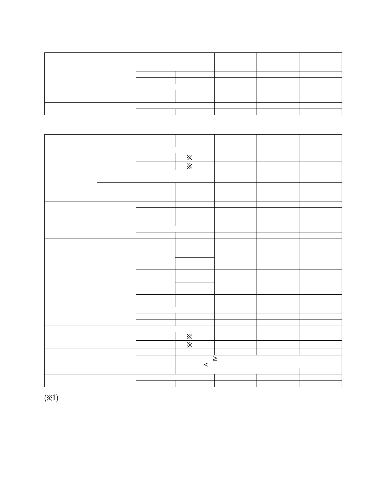
3.7. Safety Devices
INDOOR UNIT
OUTDOOR UNIT
1MPa=10.2kgf/cm
2
Indoor Unit Cooling Only Model CS-D34DTQ CS-D43DTQ CS-D50DTQ
For fan motor protection
Internal OFF °C 135 135 135
Protector (49F) ON °C868686
For condesation temperature
protection control OFF °C585858
Heater exchanger thermistor RESET °C545454
For control protection
Fuse CUT A 3.15 3.15 3.15
Outdoor Unit Cooling Only 50Hz CU-D34DBQ7 CU-D43DBQ7 CU-D50DBQ7
Model 60Hz
For refrigerant cycle
High pressure OFF
MPa
2.94 2.94 2.94
Switch (63H1) ON
MPa
2.45 2.45 2.45
For compressor
Over current protection
Cooling Only OFF A 29 11 14
Model
RESET — Automatic Automatic Automatic
Discharge temp protection
Discharge Compressor
temperature OFF °C 120 120 120
thermistor (Th1)
Liquid compress protection
Crankcase heater Input Power W NL NL NL
Compressor protection
Internal protector °C
OFF 50Hz 160 160 160
°C
60Hz
°C
ON50Hz909090
°C
60Hz
Trip 50Hz — — —
Time 60Hz — — —
For fan motor protection
Internal OFF °C 135 135 135
Protector (49F) ON °C868686
Heating control (Heat pump only)
Pressure switch OFF
MPa
———
(Fan speed) (63H2) ON
MPa
———
Cooling control
Heat exchanger
Th 40°C ——— High speed
temperature Control Method
Th 40°C ——— 5 speed step control
thermistor (Th2)
For control protection
Fuse CUT A 6.3 6.3 6.3
16
4 Dimensions
4.1. Indoor Unit
17
4.2. Outdoor Unit
18
5 Refrigeration Cycle
5.1. CS-D34DTQ CU-D34DBQ7
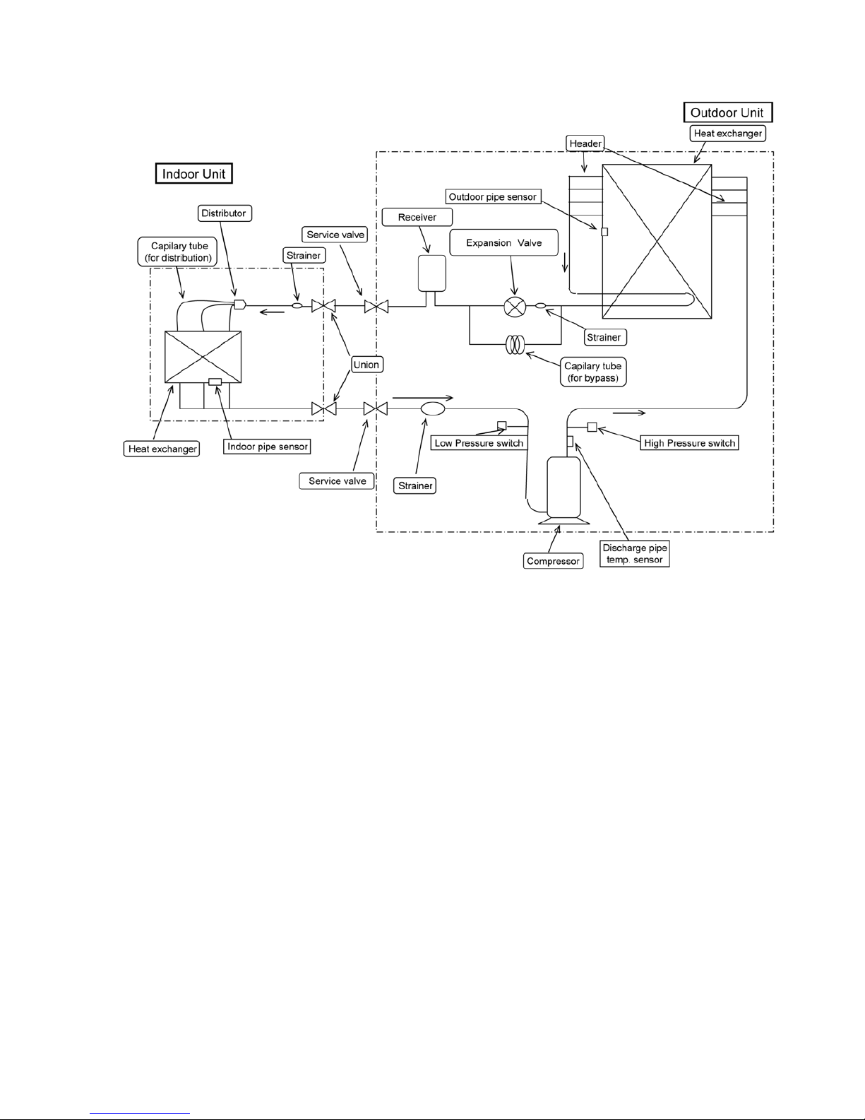
19
5.2. CS-D43DTQ CU-D43DBQ7 CS-D50DTQ CU-D50DBQ7
20
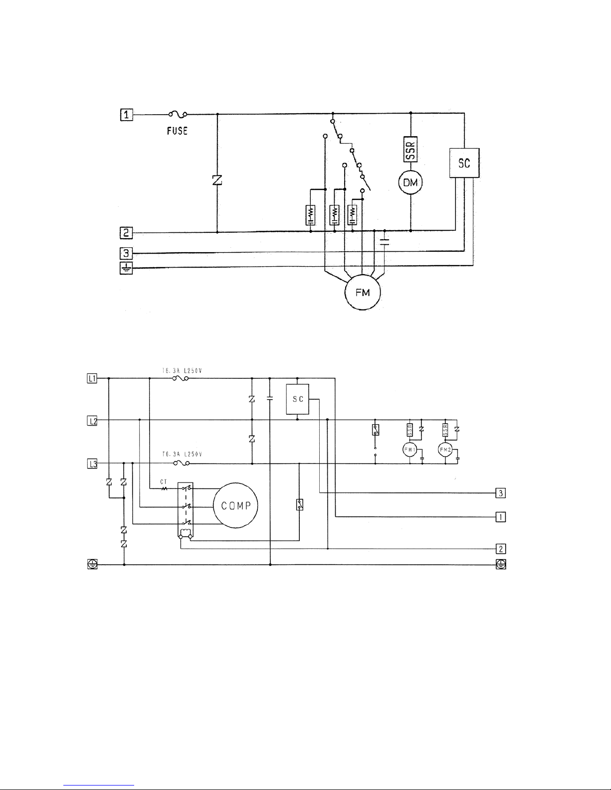
6 Block Diagram
6.1. CS-D34DTQ CS-D43DTQ CS-D50DTQ
6.2. CU-D34DBQ7 CU-D43DBQ7 CU-D50DBQ7
21
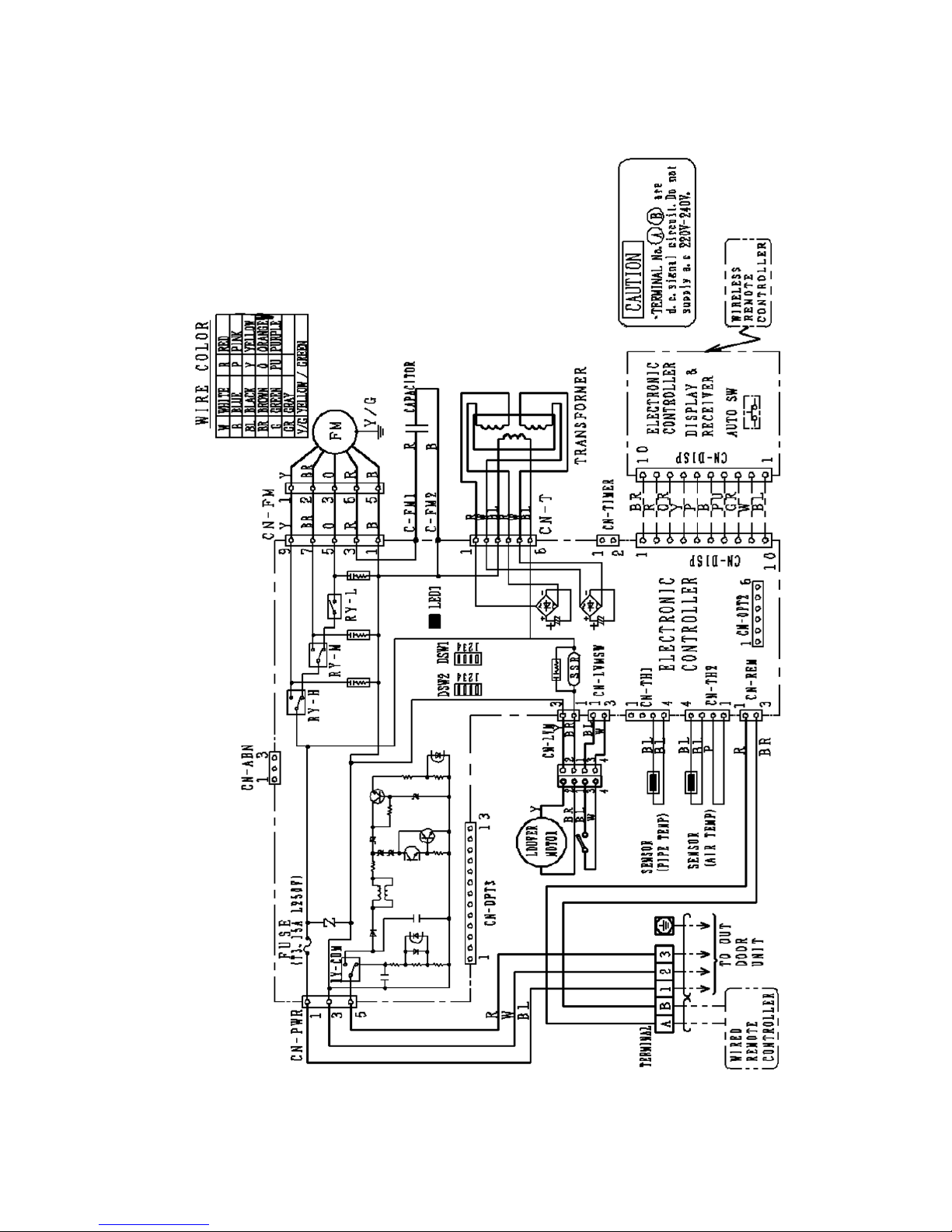
7 Wiring Diagram
7.1. CS-D34DTQ CS-D43DTQ CS-D50DTQ
22
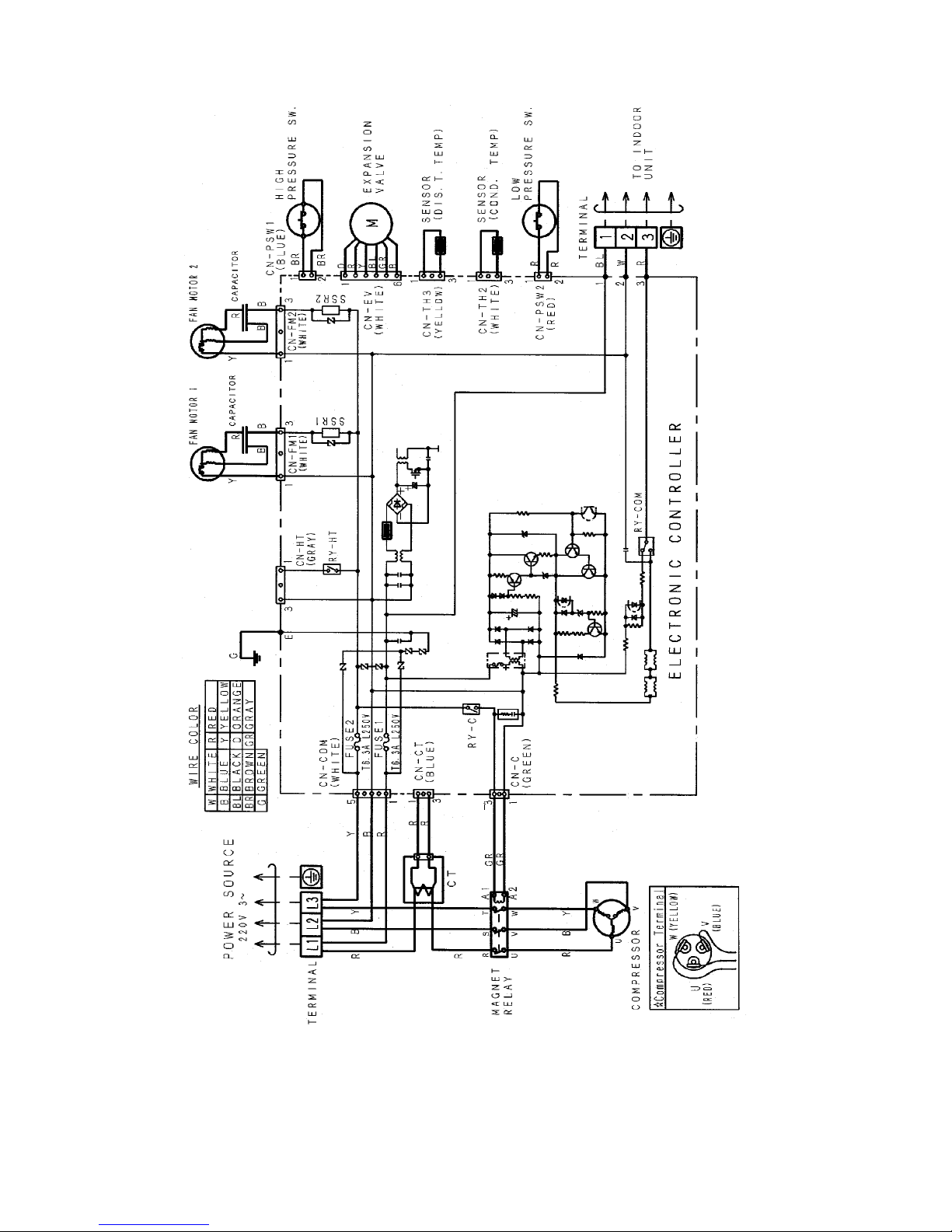
7.2. CU-D34DBQ7 CU-D43DBQ7 CU-D50DBQ7
23
8 Operation Instructions
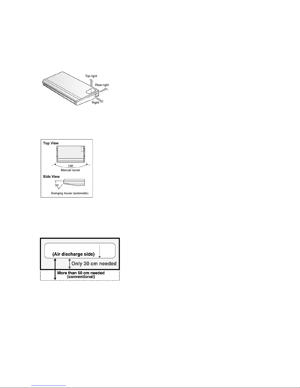
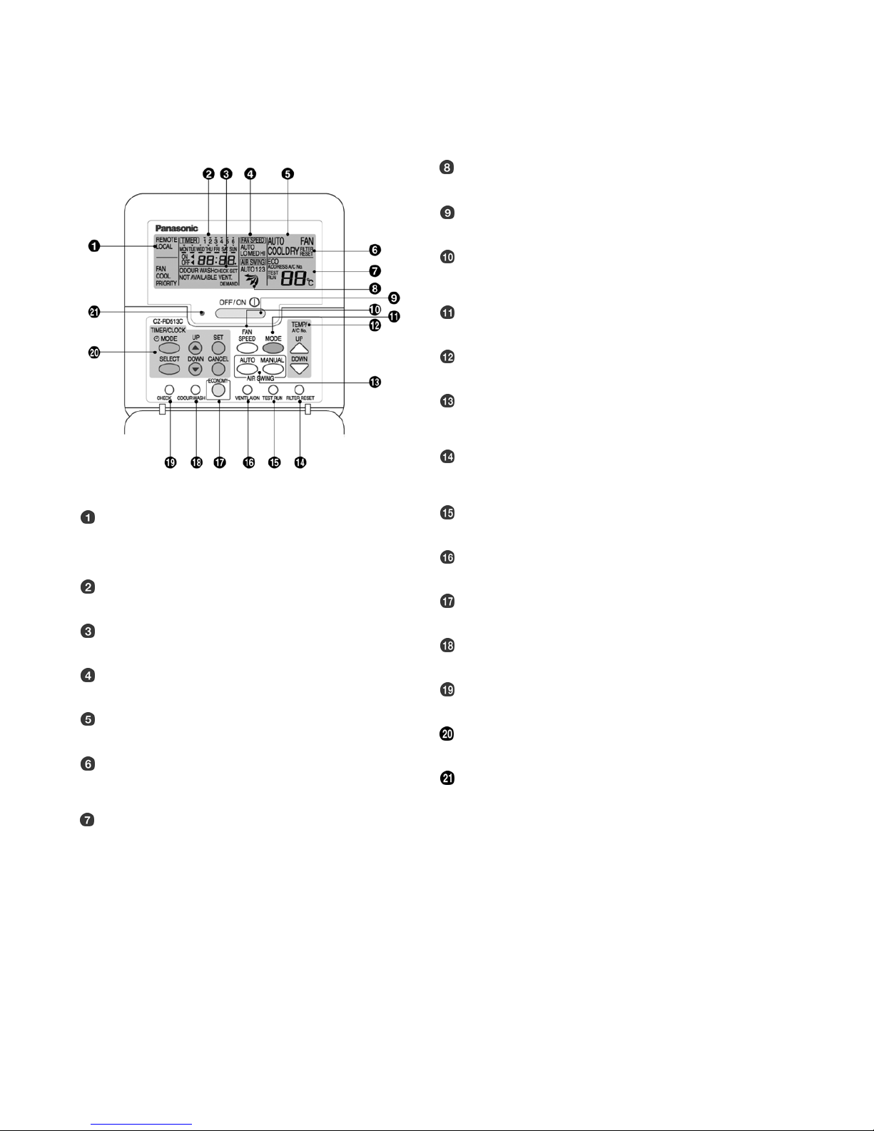
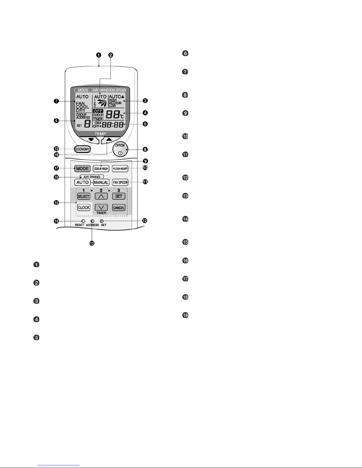
8.1. Wired Remote Control (Optional part)
Name and function of each part
NOTES
• Ensure that the correct button is pressed as simultaneous pressing of the multiple buttons will not make the setting correct.
• The illustration above is for explanatory purposes only. The appearance will be different during actual operation.
• Do not operate the remote control with wet hands. Otherwise, electric shock or malfunction may occur .
• Do not press the remote control buttons with sharp object as this may damage the remote control.
• Buttons marked with * are not needed for normal operation. If one of these buttons is pressed by mistake, press the same button
once more to cancel the operation.
• When the power resumed after power failure, the unit will restart automatically with all the previous settin gs preserved by the
memory function. (Auto restart function)
REMOTE
The OFF/ON button cannot be used.
LOCAL
All wired remote control buttons can be used.
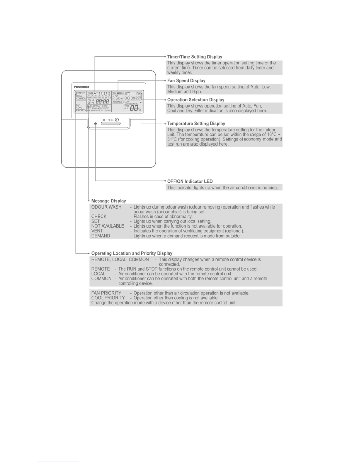
Time/time setting display
Check display
Fan speed display
Operation mode selection display
FILTER RESET display
(Appears after the cumulative running time reaches approximately 1,000 hours of operation.)
Temperature setting display (16°C - 31°C)
Airflow direction setting display
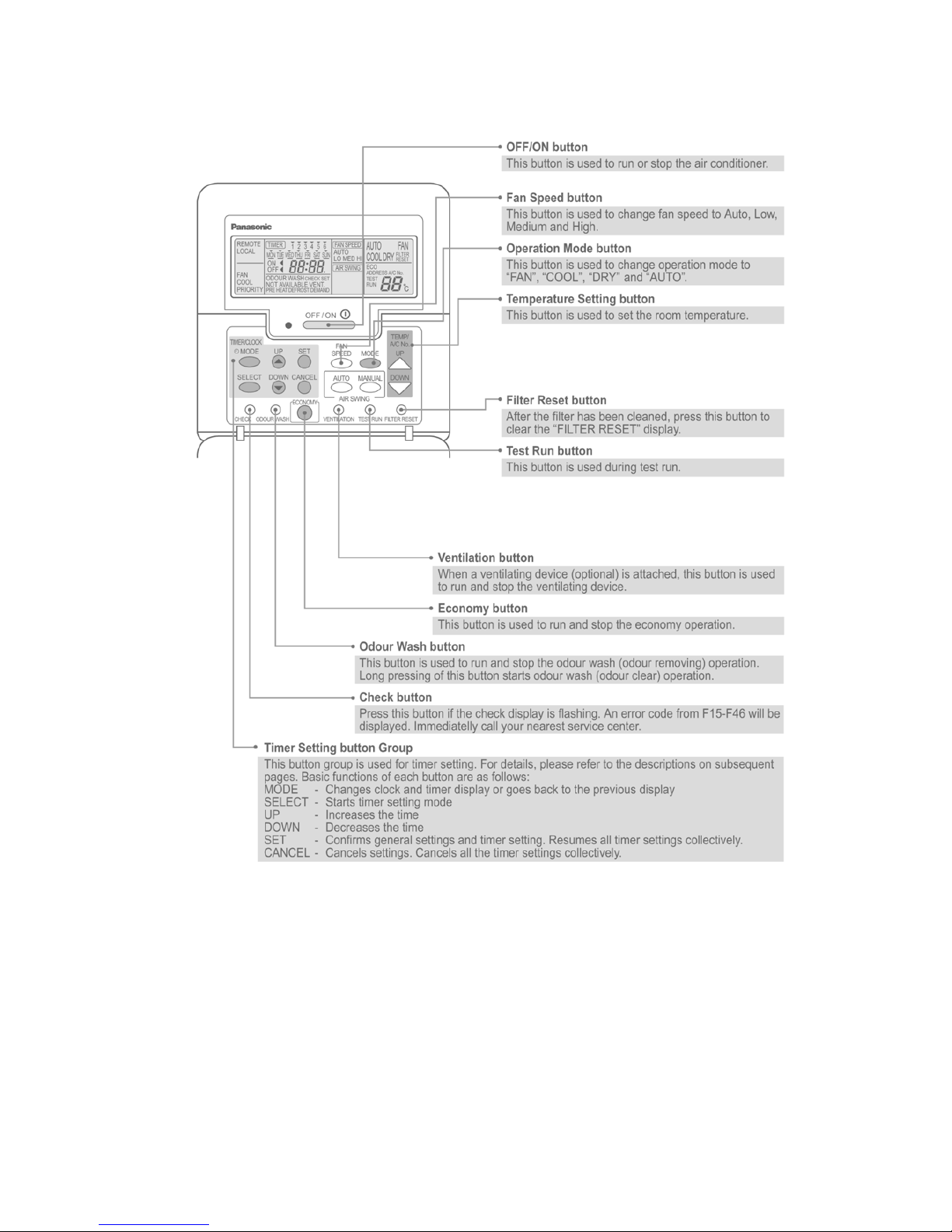
OFF/ON button
Used to start and stop the operation.
FAN SPEED button
Used to select the fan speed of high (HI), medium (MED), low
(LO) or auto (AUTO).
MODE button
Used to select the operation of AUTO, FAN, COOL, or DRY.
TEMP (UP/DOWN) buttons
Used to select the desired temperature.
AIR SWING (AUTO/MANUAL) buttons
Used to determined the air swing condition, either auto or
manual.
FILTER RESET button
Press to reset the “FILTER RESET” display after washing the filter.
TEST RUN button*
VENTILATION button*
ECONOMY operation button
Provides Energy saving function
ODOUR WASH button
Provides deodorizing function.
CHECK button
Press this button if the check display is flashing.
TIMER/CLOCK SET buttons
Used to set the timer operation and the current time.
Operation indicator
Lights up when the unit in operation.
24
8.2. Remote Control - Display
25
8.3. Remote Control - Panel
26
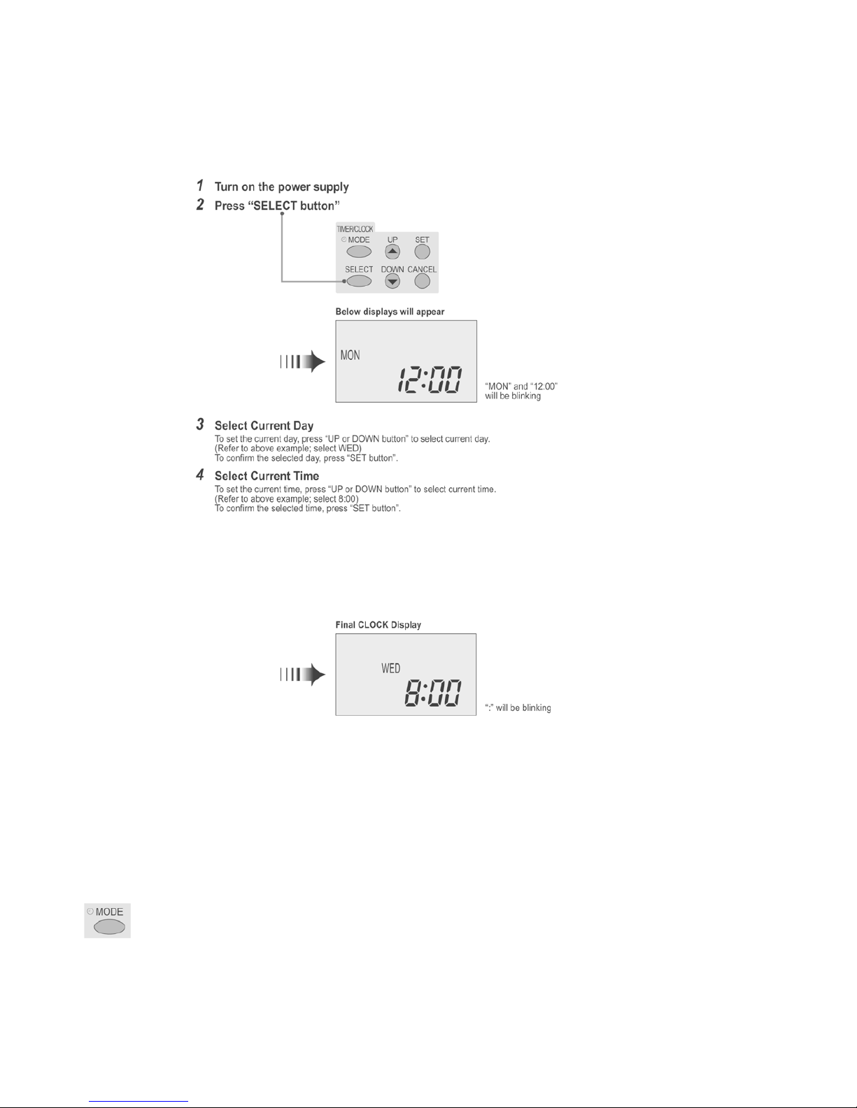
8.4. How to set remote control day and time
• The day and time needs to be set when you turn on the power for the first time or a fter a long time has elapsed since th e powe r
was last turned on.
• The day and time becomes the standard time for all the Timer operations.
• Set the day and time accurately.
• Example : Current Day is Wednesday and Current Time is 8:00.
Note:
• Press “UP button” to increase or “DOWN button” to decrease (interval 1 minute) or hold the button to change the time faster.
• If the “UP or DOWN button” is not pressed for 30 seconds during the day or time setting or if the “SELECT button” is pressed, the
setting at that moment is confirmed and setting will end.
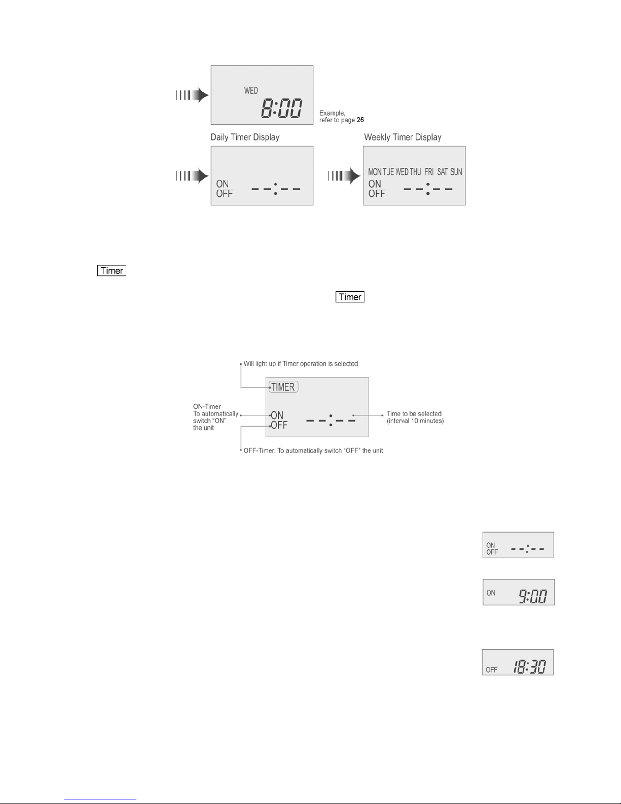
8.5. How To Select The Timer
• 2 types of Timer mode can be selected on the remote control.
- Daily Timer
- Weekly Timer
• These timers cannot be operated simultaneously.
• Select one of these Timers for your convenience.
How to Change the Display
• Press once to change the display from CLOCK to Timer or vice-versa.
• Press more than 3 seconds to change the display from Daily Timer to Weekly Timer or vice-versa.
27
CLOCK Display (To set current Day and Time)
Note:
• The above display is shown if no valid timer setting is made.
• If valid timer setting is made.
- and setting will be displayed.
- If you want to check the current time and day, press “MODE button” once.
(However, after a few seconds, the display will change back to and the setting)
8.6. Daily Timer Setting
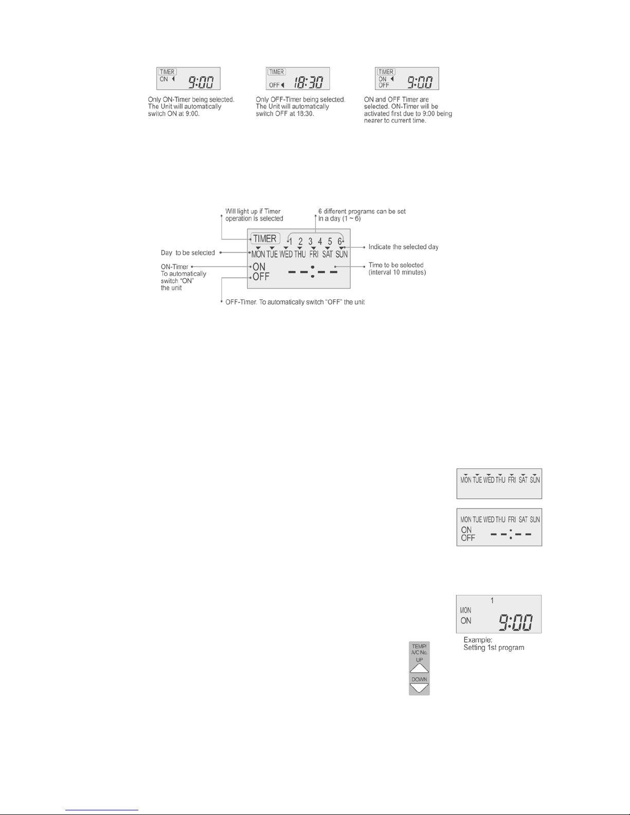
•Display
• How to Set Daily Timer
- You can set only “ON” or only “OFF” or “ON” and “OFF” in a day.
Note:
• The setting timer will be activated everyday.
• Timer nearer to the current time will be activated first.
1. Change Display
Press “MODE button” to change the display to daily timer.
2. ON-Timer, OFF-Timer and select Time
Press “SELECT button”; ON-Timer setting will be displayed.
Press “UP or DOWN button” to select the desired time, (Example: ON 9:00), then press “SET button” to confirm the
selected desired time.
Or press “CANCEL button” if you do not want any setting for ON-Timer.
Then OFF-Timer setting will be displayed.
Press “UP or DOWN button” to select the desired time, (Example: OFF 18:30), then press “SET button” to confirm
the selected desired time.
Or press “CANCEL button” if you do not want any setting for ON-Timer.
28
Final Display of Daily Timer:
8.7. Weekly Timer Setting
• Display
• How to Set Weekly Timer
- You can set the Timer for 1 week (Monday to Sunday) with 6 programs per day.
- ON-Timer can be set together with your desired temperature. However, this temperature will be used continuously.
- Cannot set 2 programs with same time setting in a day.
- You also may select Collective - many days with same ti me setting or Individual
- single/one day setting.
1. Change Display
Press “MODE button” to change the display to weekly timer.
2. Select Day (please refer to next page for example of setting)
You may select Collective or Individual day setting.
• Collective day setting.
Press “SELECT button”: display will show day selection setting.
Press “UP or DOWN button” to select the day. Then press “SET button” to delete triangle
mark (deselect) or add triangle mark (select).
(Triangle mark on top of each day indicates the day to be selected).
Repeat these steps if you want to deselect or select many days.
To confirm the selected days, press the “SELECT button”.
• Individual day setting.
Press “UP or DOWN button” to select the day.
Then press “SELECT button”.
3. Select Time (please refer to next page for example of setting)
For 1st program setting.
Press “UP or DOWN button” to select ON or OFF.
Then press “SET button” to confirm.
Press “UP or DOWN button” again to select the desired time.
(If you want to set them together with your desired temperature, press “TEMP UP/DOWN button”
to select the temperature).
Then press “SET button” to confirm.
Or press “CANCEL button” if you do not want to set any time.
For 2nd ~ 6th program you may refer to the above step.
29
Note:
• Timer that has setting nearest to current time and day will be activated first.
• To check the setting timer, press “SELECT button”, then “UP or DOWN button” to select day. The display will show each program
for the selected day.
• To reset the setting for all, press “SELECT button”, then ensure all day setting with triangle mark. Then press “CANCEL button ”
for all the programs.
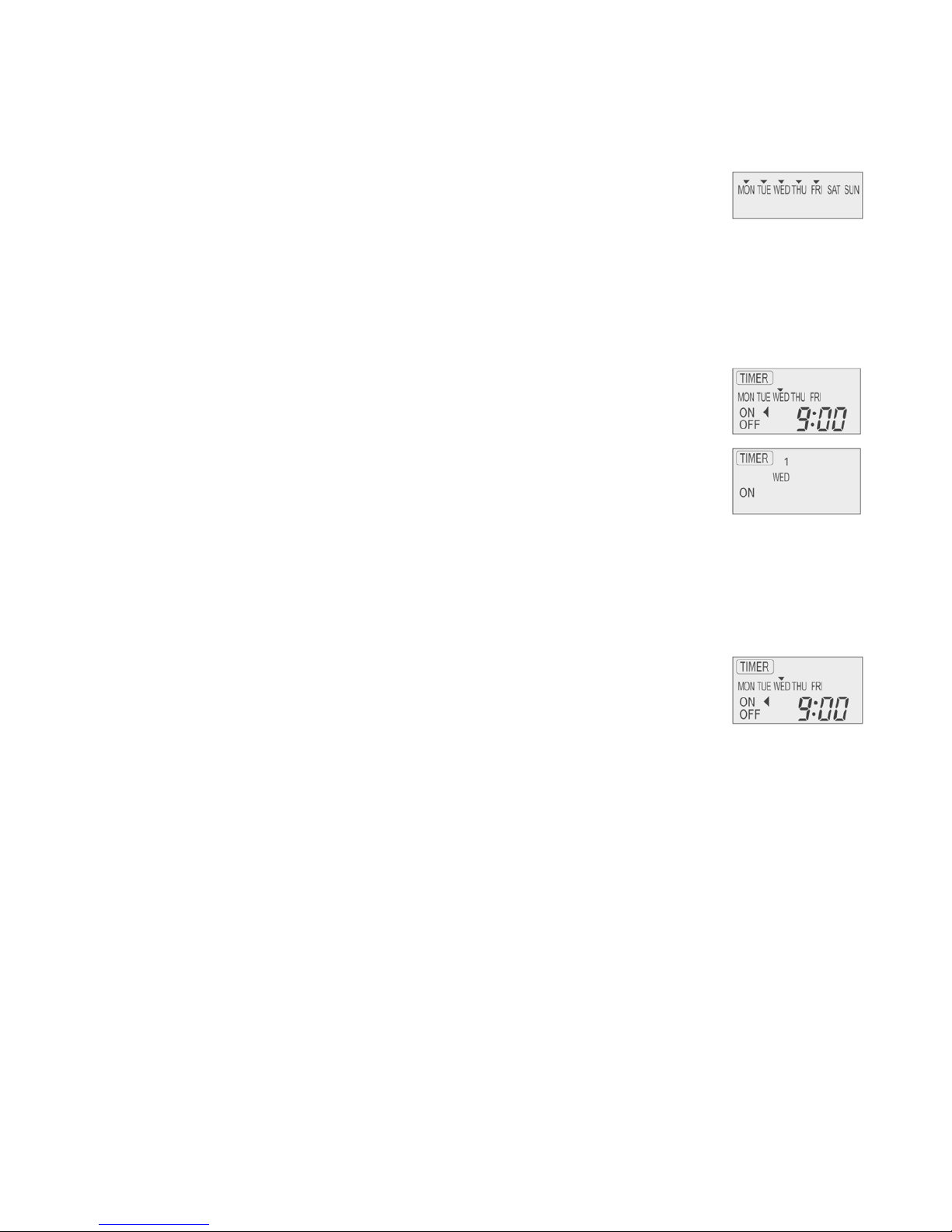
For example , if you want to set:
A - Monday to Friday: Same time, 1st program ON 9:00 & 2nd program OFF 16:00.
B - Only Wednesday: Additional 3rd program OFF 12:30 & 4th program ON 13:30.
C - Only Saturday: 1st program ON 10:00 with 20°C & 2nd program OFF 14:00.
D - Sunday: Holiday. No need to set any Timer.
• To set A (Monday to Friday - Collective day setting)
Press “SELECT button”
To select Monday to Friday, deselect Saturday and Sunday by pressing “UP or DOWN button” to Saturday, press
“SET button” (triangle mark on top of Saturday will disappear)
Follow the same step to deselect Sunday.
Ensure triangle mark appears on top of Monday ~ Friday.
- To confirm the selected days, press “SELECT button”.
To set the time, please refer to step 3. Select time at page 28.
- 1st program - select ON and desired time to 9:00.
2nd program - select OFF and desired time to 16:00.
3rd ~ 6th program - press “CANCEL button”.
• To set B (Wednesday - Individual day setting)
- Press “UP or DOWN button” to select WED (Wednesday).
Then press “SELECT button”.
To set the time, please refer to step 3. Select time at page 28.
- 1st program - press “SET button” twice (confirm ON and 9:00)
2nd program - also press “SET button” twice. (Confirm OFF and 16:00)
3rd program - select OFF and desired time to 12:30
4th program - select ON and desired time to 13:30
5th ~6th program - press “CANCEL button”
• To set C (Saturday - Individual day setting)
- Follow the same step as above.
To set the time, please refer to step 3. Select time at page 28.
- 1st program - select ON, desired time to 10:00 and desired temperature to 20°C.
2nd program - select OFF and desired time to 14:00.
3rd ~ 6th program - press “CANCEL button”.
- Final Display for Weekly timer may show as:
(Display is showing, 9:00 ON - Timer on Wednesday will be activated next because it is nearest the current
day/time.)
30
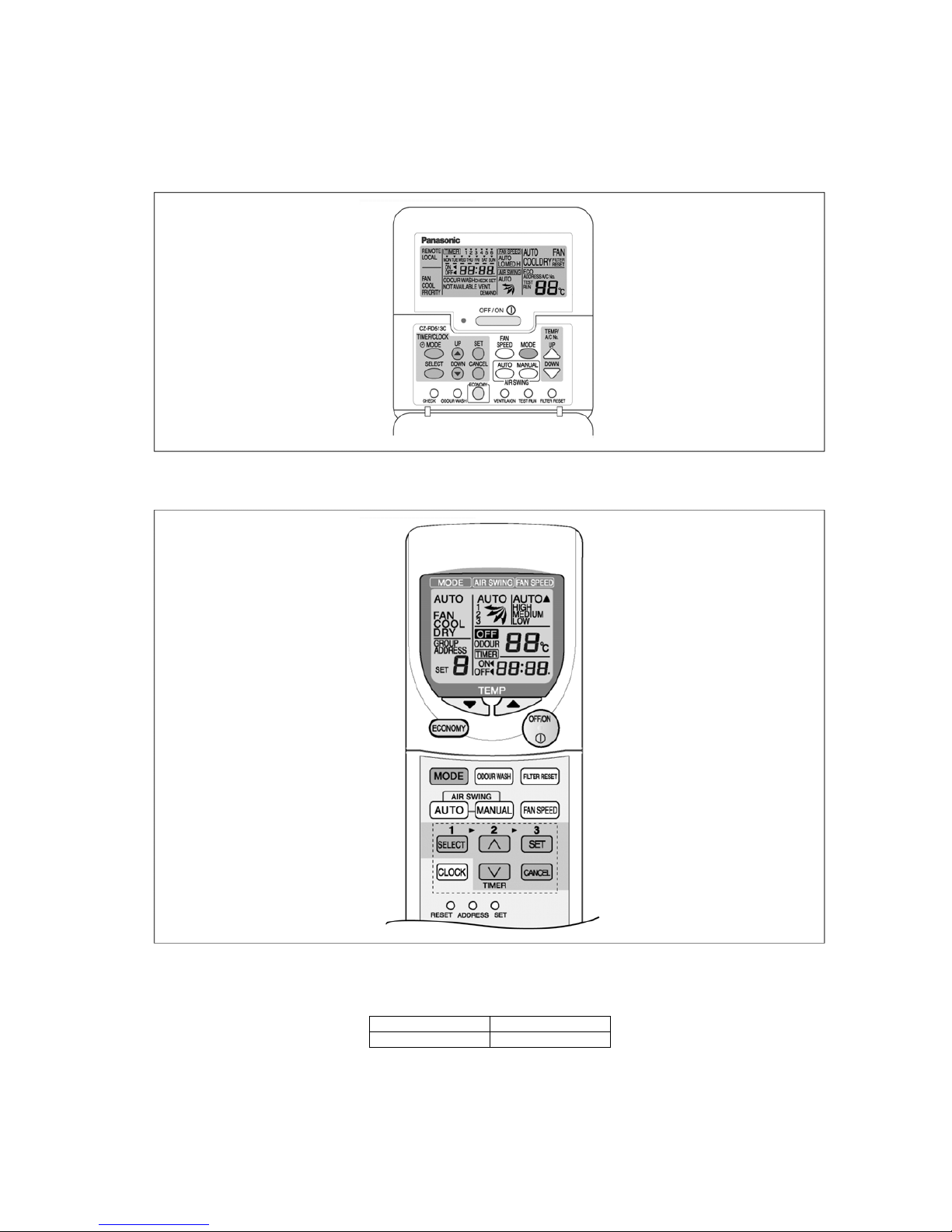
8.8. Wireless Remote Control (Optional part)
Name and function of each part
NOTES
• Ensure that the correct button is pressed as simultaneous pressing of the multiple buttons will not make the setting correct.
• The illustration above is for explanatory purpose only. The appearance will be different during actual operation.
• If using the wireless remote control in conjunction with the wired remote control, the settings made from the wireless remote control will appear on the wired remote control display (except when making timer settings).
• Buttons marked with * are not needed for normal operation. If one of these buttons is pressed by mistake, press the same button
once more to cancel the operation.
• When the power resumed after power failure, the unit will restart automa tically with a ll previo us settings preserved b y the me mory function. (Auto restart function)
Transmitter
Transmits the remote control signal.
Airflow direction setting display
Fan speed display
Temperature setting display (16°C - 31°C)
Time/time setting display
Shows the timer operation setting time or the current time.
Address number display
Operation selection display
OFF/ON button
Used to start and stop the operation.
ODOUR WASH button
FILTER RESET button
Press to cancel the “FILTER” indicator light on the control panel.
FAN SPEED button
Used to select the fan speed of high (HI), medium (MED), low
(LO) or auto (AUTO).
SET button*
Local setting function.
ADDRESS SET button*
Used to change the address setting when using more than one
indoor unit.
RESET button
Pressing this button will clear all the settings from memory.
You will then need to make the settings again.
TIMER/CLOCK SET buttons
Used to set the timer operation and the current time.
AIR SWING (AUTO/MANUAL) buttons
Used to determine the air swing condition, either auto or manual.
MODE button
Used to select the operation of AUTO, FAN, COOL or DRY.
TEMP (UP/DOWN) buttons
Used to select the desired temperature.
ECONOMY operation button
 Loading...