

Panasonic CS-A18BTP, CU-A18BBP5, CU-C18BBP5 Service Manual
ORDER NO. MAC0208029C8
AIR CONDITIONER
CS-A18BTP CU-A18BBP5
CS-A18BTP CU-C18BBP5
CONTENTS
Page Page
1 SERVICE INFORMATION 3
2 FEATURES
3 SPECIFICATION (HEAT PUMP TYPE )
4 SPECIFICATION (COOLING ONLY TYPE )
5 TECHNICAL DRAWING
6 CIRCUIT DIAGRAM
7 OPERATING INSTRUCTION
8 REFRIGERATION CYCLE
9 OPERATION RANGE
10 PIPE LENGTH
11 OPERATIN G CHARACTERIS TIC
12 FAN PERFORMANCE
13 SAFETY DEVICE
14 COMPONE NT SPECIFICA TION
15 CAPACITY AND POWER CONSUMPTION
16 DISCHARG E AND SUCTION PRESSURE
17 POSITION OF THE CENTRE GRAVITY
18 REACHING DISTANCE 39
4
19 SOUND DATA
8
20 TWIN AND TRIPLE
21 WIRING MISTAKE PREVENTI ON
9
10
22 TEST OPERATION AND SELF DIAGNOSIS
12
23 SETTING OF SAVE ENERGY AND THERMISTOR SWITCH
24 GROUP CONTROL
24
26
25 TROUBLE SHOOTING
28
26 EMERGEN CY OPERATIO N
29
27 CONTROL
28 WIRED REMOTE CONTROL INSTALLATION MANUAL
31
32
29 WIRELESS REMOTE CONTROL INSTALLATION MANUAL
33
30 INSTALLATION (INDOOR UNIT)
31 INSTALLATION (OUTDOOR UNIT)
34
35
32 REPLACEMENT PARTS
37
33 HEA TING CAPACITY PERFORMANCE DATA
38
© 2002 Matsushita Industrial Corporation Sdn. Bhd.
(11969-T). All rights reserved. Unauthorized copying
and distribution is a violation of law.
40
42
47
48
52
53
54
59
60
70
75
82
91
101
110

34 COOLING CAPACITY PERFORMANCE DATA 111
2

1 SERVICE INFORMATION
Caution:
●
Pb free solder has a higher melting point than standard solder; Typically the melting point is 50 - 70°F (30 - 40°C) higher. Please use
a high temperature soldering iron. In case of the soldering iron with temperature control, please set it to 700 ± 20°F (370 ± 10°C).
●
Pb free solder will tend to splash when heated too high (about 1100° F/600°C).
Notice of Address setting for NEW Ceiling / NEW Outdoor Unit.
The new Ceiling / new Outdoor models are possible to have address setting for twin / triple control or group control
automatically when main power supply is switched on.
(Manual address setting is also possible by using DSW1 switch on the indoor unit P.C. board.) However,
only possible when proper wiring connection is made and indoor unit must be of original unit
1.1. Example of trouble during test operation
If the below phenomenon is found during test operation, wrong address setting is possible.
Therefore, please inspect the address setting.
1. LCD display of the wired remote control is not illuminated although the main power supply switch is ‘on’.
2. LCD display had indicated as normal illumination when power supply switch is ‘on’, however outdoor unit cannot be operated.
(But, it is necessary to take 3 to 5 minutes for outdoor unit to start from the timing of remote control OFF/ON button is ‘on’.)
(For normal operation, the outdoor unit will only start its operation after 3 to 5 minutes upon pressing the OFF/ON button.)
3. P.C. board had memorized wrong setting information.
a. If main power supply is switched on with the wrong connection.
b. When changing the connection or combination of units due to re-installation etc.
•
•
When changing the system from twin to triple (triple to twin).
• •
•
•
When changing the system from group control to normal one to one system.
• •
•
•
When making the replacement of units of master and slave etc.
• •
this address setting is
.
1.2. Caution during test operation
Do not touch the remote control button and do not change any wirings for one minute when the main power supply switch is ‘on’.
(Because the unit is having automatic address setting during the first one minute.)
1.3. Caution during automatic address setting
When the main power supply switch is ‘on’, the P.C. board will automatically memorize the connecting system.
Consequently, when initial power supply is ‘on’, there mustn’t be any interchanging of units even of the same type and same
capacity unit.
Therefore, connection of the unit to another system is prohibited.
3
2 FEATURES
2.1. New design
2.1.1. Gentle curved styling
•
• The base has gentle curves which express a functional
• •
beauty. It spreads the air quietly over a wide area.
2.2. Such quietness!
2.2.1. Several new mechanism add up to
low 36 dB noise (A18BT - High Fan
Speed)
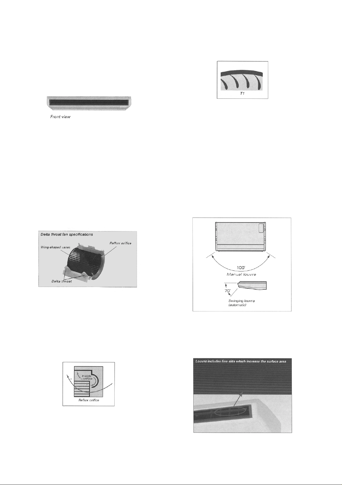
1. Delta throat fan
A delta throat (projection) has been attached to the fan
outlet to suppress the generation of vortexes. This helps
maintain air flow sped even at lower fan speeds and is
effective in reducing noise.
3. Adoption of wing-shaped vanes
•
• The vanes of the fan have been changed to
• •
“aerodynamic” shaped vanes, so that the air flow more
smoothly over the vane surfaces and noise is thus
suppressed.
•
• Side filters have been adopted in the pipe partitions.
• •
These allow the air intake space to be increased and
also further reduce noise.
2.2.2. Automatic swinging louvre
•
• The horizontal air flow angle is a wide 100 degrees
• •
(manual). The louvre can swing automatically (through 70
degrees vertically) using the remote control. This increases
the area of comfortable air flow and warms the air even to
floor level.
2. Reflux orifice
The orifice at the intake port is equipped with an air flow
guide which minimizes the flow disturbances which occur at
the orifice and inside the impeller.
This reduces pressure losses inside the casing and also
helps reduce noise.
2.2.3. Newly-shaped louvre
•
• The newly-shaped louvre and air outlet effectively distribute
• •
the air flow. During cooling, this stops warm air from
collecting near the louvre, and prevents freezing.
4
2.3. Easy installation
2.3.1. Easy suspension
•
• A suspension bolt fixing bracket with 4-point support is
• •
attached to the main unit, which increases the space
available for installation.
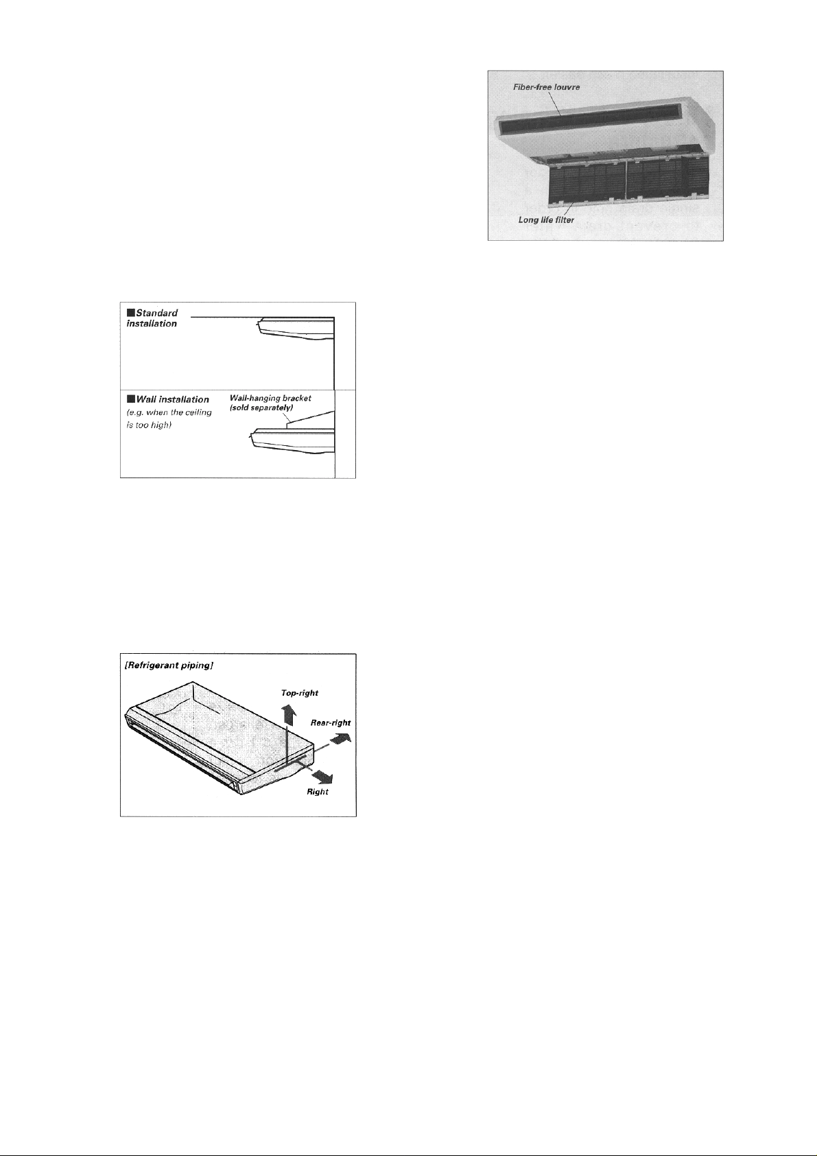
2.3.2. Two installation methods :
standard and wall
•
• In addition to the standard (1) ceiling installation, a wall (2)
• •
installation method (using a wall-hanging bracket) is
available for cases where the ceiling is too high for the main
unit to be suspended.
2.5.2. Maintenance is possible from
underneath the unit.
•
• If the bottom panel is detached, the drain pan can then be
• •
removed and installed from underneath the unit, and
inspection and servicing of component such as the control
panel also becomes easier.
2.6. Auto fan mode (indoor unit)
•
• Auto fan mode is added besides high, medium and low. It
• •
automatically adjusts the fan speed according to the indoor
unit’s temperature.
2.4. Piping
2.4.1. 3-direction pipe lead-out
•
• The refrigerant piping can lead out in one of three directions
• •
(right, rear-right and top-right), and the drain pipe direction
can be selected from four directions (right, rear-right, left
and rear-left).
2.5. Easy maintenance
2.5.1. Long life filter (standard
equipment)
•
• In general office environments, cleaning (maintenance) is
• •
not required until after approximately 2,500 hours of
operation, thus reducing maintenance work.
•
• For optimum comfort, it is recommended to clean the air
• •
filter every 1-1/2 months.
2.7. Hot start system (heat pump
models)
2.8. Automatic changeover
function (heat pump models)
•
• The unit automatically switches between cooling and
• •
heating in accordance with operating load in order to
maintain a comfortable indoor temperature.
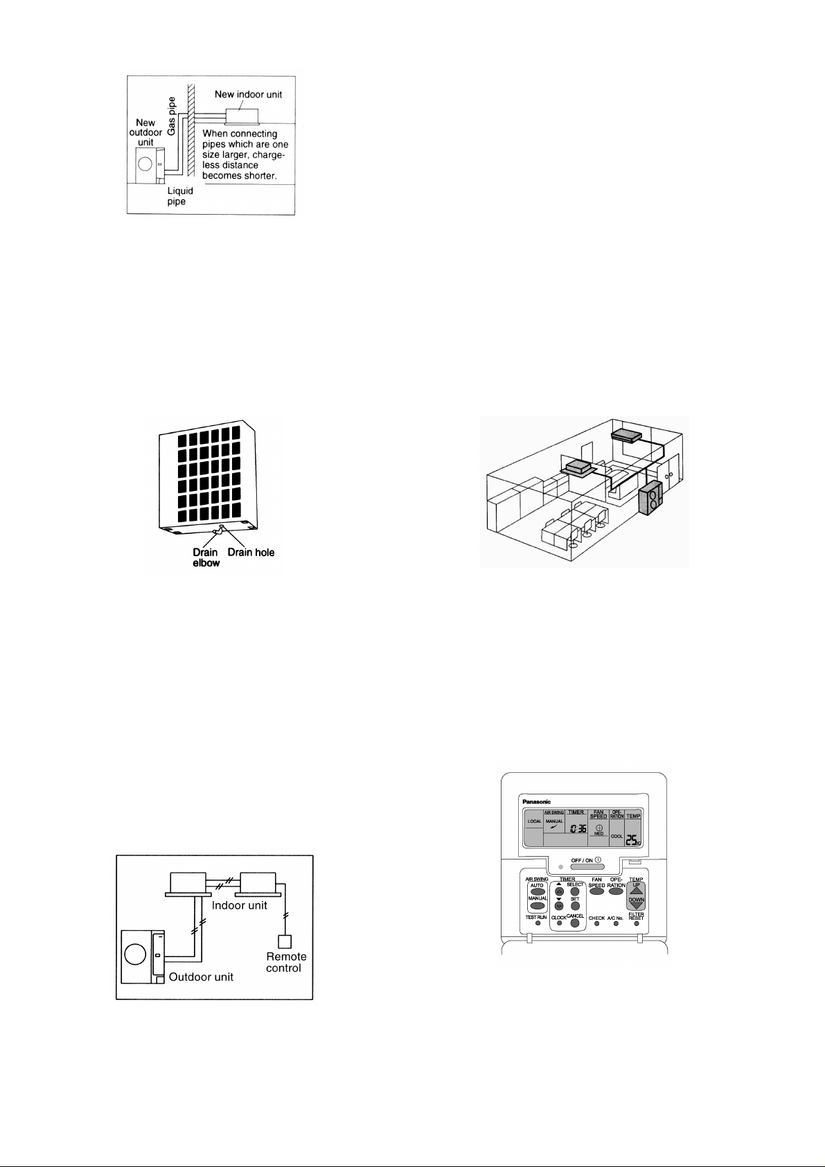
2.9. Greatly improved workability
increases system renewal
capability
Pipes that are one size larger can also be connected for
•
•
• •
renewal.
−
− If renewing the system, existing refrigerant pipes can be
− −
utilized so that only the indoor and outdoor units need to
be replaced.
−
− For example, liquid and gas pipes from 10 years ago
− −
can be connected to current pipes with the same size or
one size larger. Effective utilization of materials reduces
working time and trouble. (Adaptor sockets are not
supplied.)
5
•
• Additional refrigerant charging unnecessary for 10 m
• •
−
− All models do not require any additional charging of
− −
refrigerant for 10 m of pipe length. This makes
installation much easier.
•
• Drain water dripping-prevention structure
• •
−
− The base of the outdoor unit is provided with a single
− −
drain hole in order to prevent drain water from leaking
out of the unit. By connecting a drain elbow and a
discharge pipe, water leakages can be prevented even
when the unit is installed to a wall.
−
− Master unit and slave-units can be set automatically in
− −
twin and triple systems. No address setting is
necessary.
−
− Multiple indoor units can be operated simultaneously
− −
with a single remote control. Note that individual
operation is not possible.
•
• Separate indoor/outdoor unit power supplies
• •
The power supply can be connected to (1) just the outdoor
units, or (2) to both the indoor and outdoor units.
•
• Easy test operation
• •
Test operation can be carried out for both indoor and
outdoor units.
•
• Automatic setting initialization function (Remote control
• •
and Indoor unit)
In accordance with the indoor and outdoor units connected
and the connection methods, conditions such as the
connection configuration (twin or triple format) and remotecontrol functions such as automatic louvre operation and
cooling or heating mode are automatically detected and set
instantly.
•
• Long pipe design for refrigerant pipes
• •
−
− Maximum piping length of 25m for all models.
− −
2.10. A brand-new control method
using the latest in technology
•
• Easier power supply wiring connection
• •
Power supply wiring and other wiring tasks can be carried
out more easily.
−
− Twin non-polar wires used to connect indoor and
− −
outdoor units.
−
− Adoption of connection error prevention circuits for drive
− −
wires and signal wires. If a connection error is made, the
relay does not operate and current does not flow to the
circuit boards.
2.11. Wired Remote Control
•
• The new design includes an easily-visible red pilot lamp.
• •
The power can be turned on and off at a single touch,
without opening the cover.
•
• Has a build-in thermistor, allowing indoor temperature
• •
detection in accordance with indoor conditions by switching
with main unit thermistor.
•
• Twin non-polar wires make installation work easy. (10 m
• •
cable supplied as accessory.)
•
• Twin and Triple operation
• •
−
− Simultaneous air conditioning of wide spaces and
− −
corners is possible. Indoor units of different
horsepowers can even be used in combination.
6
2.12. Wireless Remote Control
2.13. Group Control Equipment
•
• New design with compact size. (Operation range within
• •
approximately 8 m.)
•
• Built-in timer with ON/OFF timer setting (within 24 hours)
• •
Wired Wireless
Heat Pump CZ-RD51P CZ-RL51P
Cooling CZ-RD51P CZ-RL01P
NOTE: Both of the above remote control is packed separately
from the indoor unit.
7
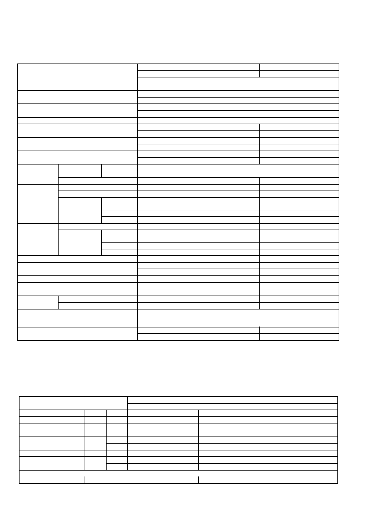
3 SPECIFICATION (HEAT PUMP TYPE )
3.1. CS-A18BTP / CU-A18BBP5
ITEM / MODEL Indoor Unit Outdoor unit
Main Body CS-A18BTP CU-A18BBP5
Remote CZ-RD51P (Wired)
Control CZ-RL51P (Wireless)
Cooling Capacity kW 5.0
BTU/h 17,100
Heating Capacity kW 5.6
BTU/h 19,100
Refrigerant Charge-less m 10
Standard Air Volume for High, m3/min 14 Hi 43
Medium and Low Speed cfm 494 1518
Outside Dimension (H x W x D) mm 210 x 1245 x 700 685 x 800 x 300
inch 8-17/32 x 49-1/64 x 27-9/16 26-31/32 x 31-1/2 x 11-13/16
Net Weight kg 33 56
lbs 73 123
Piping
Connection
Compressor Type, Number of Set - Hermetic-1 (Rotary), 1
Fan Type, Number of Set Sirocco fan-4 Propeller fan-1
Air-heat Exchanger Slit-fin type Louvre-fin type
Refrigerant Control Cool Capillary tube -
Refrigerant Oil (Charged) litre - M60 (0.67)
Refrigerant (Charged) kg - (2.0)
Running
Adjustment
Safety Devices Internal protector for compressor, Internal thermostat for fan motor,
Noise Level dB (A) Hi 40 Lo 36 Heating:55 Cooling:54
Refrigerant Gas mm (inch) O.D Ø 12.7 (1/2) Flared Type
Liquid mm (inch) O.D Ø 6.35 (1/4) Flared Type
Drain mm O.D Ø 20 I.D Ø 20 x 1
Starting Method - Direct on-line starting
Motor Type - 2-pole single phase induction
motor
Input kW - Cool/Heat 2.31/2.30
Rated Output kW - 1.5
Motor Type 4-pole single phase induction motor 4-pole single phase induction
motor
Input kW 0.08 0.11
Rated Output kW 0.03 0.045
Heat - Capillary tube
oz (71)
Control Switch Wireless or Wired Remote Control Room Temperature Thermostat (Main Body) -
Crankcase heater, High and heating pressure switch, Current
transformer
Power level dB Hi 57 Lo 53 Heating:68 Cooling:67
1. Cooling capacities are based on indoor temperature of 27°C D.B. (80.6°F D.B.), 19.0°C W.B. (66.2°F W.B.) and outdoor air
temperature of 35°C D.B. (95°F D.B.), 24°C W.B. (75.2°F W.B.)
2. Heating capacities are based on indoor temperature of 20°C D.B. (68°F D.B.) and outdoor air temperature of 7°C D.B. (44.6°F
D.B.), 6°C W.B. (42.8°F W.B.)
ELECTRICAL DATA (50Hz)
ITEM / MODEL CS-A18BTP, CU-A18BBP5
Condition by JIS B 8615
Volts V 220 230 240
Phase Single Single Single
Power Consumption kW Cool 1.90 1.90 1.90
Heat 1.88 1.88 1.88
Running Current A Cool 8.7 8.5 8.4
Heat 8.6 8.4 8.3
Starting Current A 38 40 42
Power Factor % Cool 99 97 94
Heat 99 97 94
*Power Factor means total figure of compressor, indoor fan motor and outdoor fan motor.
Panasonic Power source AC, 1~220, 230, 240V 50Hz
8
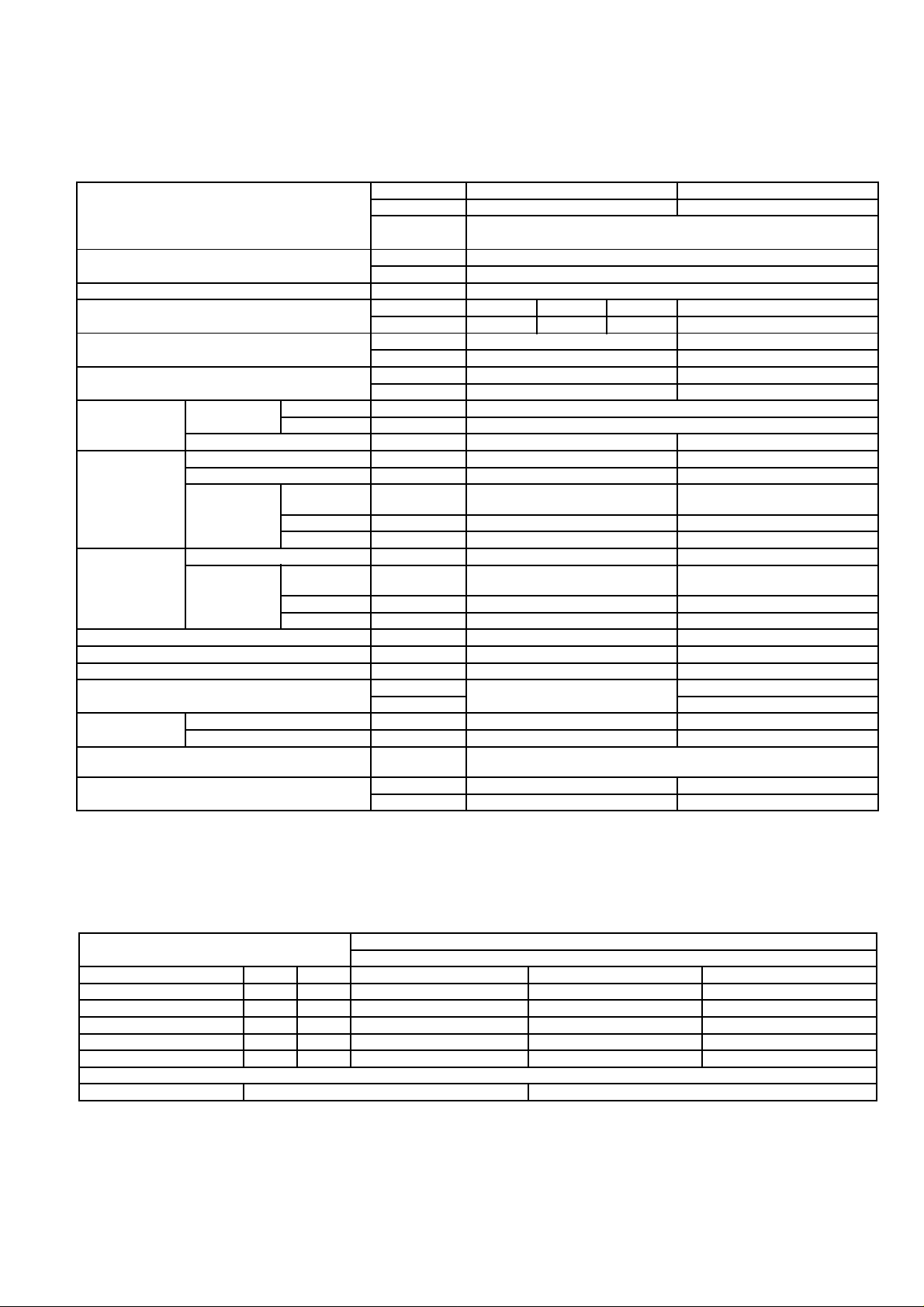
4 SPECIFICATION (COOLING ONLY TYPE )
4.1. CS-A18BTP / CU-C18BBP5
ITEM / MODEL Indoor Unit Outdoor unit
Main Body CS-A18BTP CU-C18BBP5
Remote CZ-RD51P (Wired)
Control CZ-RL01P (Wireless)
Cooling Capacity kW 5.0
BTU/h 17,100
Refrigerant Charge-less m 10
Standard Air Volume for High, m3/min Hi 17 Me 15 Lo 14 Hi 43
Medium and Low Speed cfm 600 530 494 1518
Outside Dimension (H x W x D) mm 210 x 1,245 x 700 685 x 800 x 300
inch 8-17/32 x 49-1/64 x 27- 9/16 26-31/32 x 31-1/2 x 11-13/16
Net Weight kg 33 52
lbs 73 115
Piping Connection Refrigerant Gas mm (inch) O.D Ø 12.7 (1/2) Flared Type
Liquid mm (inch) O.D Ø 6.35 (1/4) Flared Type
Drain mm O.D Ø 20 I.D Ø 20 x 1
Compressor Type, Number of Set - Hermetic-1 (Rotary), 1
Starting Method - Direct on-line starting
Motor Type - 2-pole single phase induction
Input kW - Cool 2.31
Rated Output kW - 1.5
Fan Type, Number of Set Sirocco fan-4 Propeller fan-1
Motor Type 4-pole single phase induction motor 4-pole single phase induction
Input kW 0.08 0.11
Rated Output kW 0.03 0.045
Air-heat Exchanger Slit-fin type Louvre-fin type
Refrigerant Control Capillary tube Refrigerant Oil (Charged) litre - M60 (0.67)
Refrigerant (Charged) kg - (1.6)
oz (56)
Running
Adjustment
Safety Devices Internal protector for compressor, Internal thermostat for fan motor,
Noise Level dB (A) Hi 40 Lo 36 Cooling: 54
Control Switch Wireless or Wired Remote Control Room Temperature Thermostat (Main Body) -
Crankcase heater, High pressure switch, Current transformer
Power level dB Hi 57 Lo 53 Cooling: 67
motor
motor
1. Cooling capacities are based on indoor temperature of 27°C D.B. (80.6°F D.B.), 19.0°C W.B. (66.2°F W.B.) and outdoor air
temperature of 35°C D.B. (95°F D.B.), 24°C W.B. (75.2°F W.B.)
ELECTRICAL DATA (50Hz)
ITEM / MODEL CS-A18BTP, CU-C18BBP5
Condition by JIS B 8615
Volts V 220 230 240
Phase Single Single Single
Power Consumption kW Cool 1.90 1.90 1.90
Running Current A Cool 8.7 8.5 8.4
Starting Current A 38 40 42
Power Factor % Cool 99 97 94
*Power Factor means total figure of compressor, indoor fan motor and outdoor fan motor.
Panasonic Power source AC, 1~220, 230, 240V, 50Hz
9
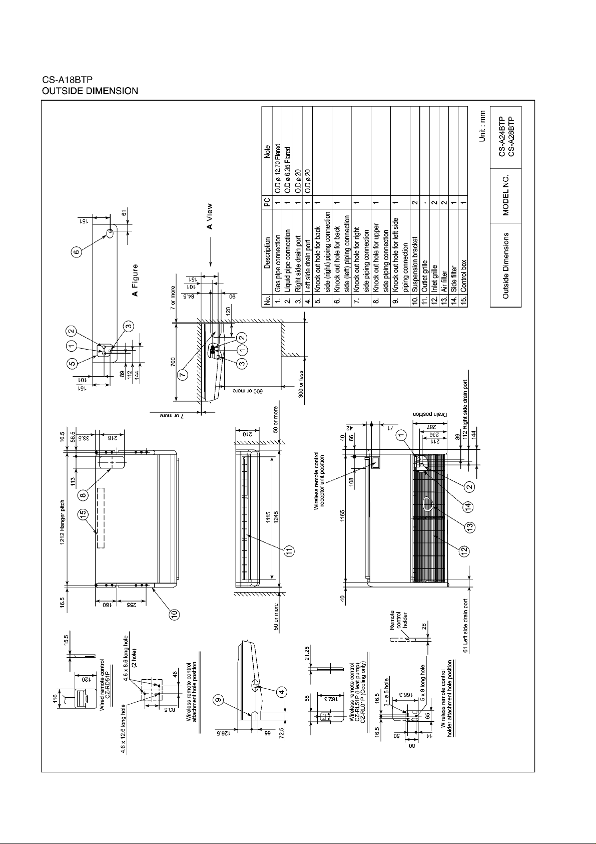
5 TECHNICAL DRAWING
10
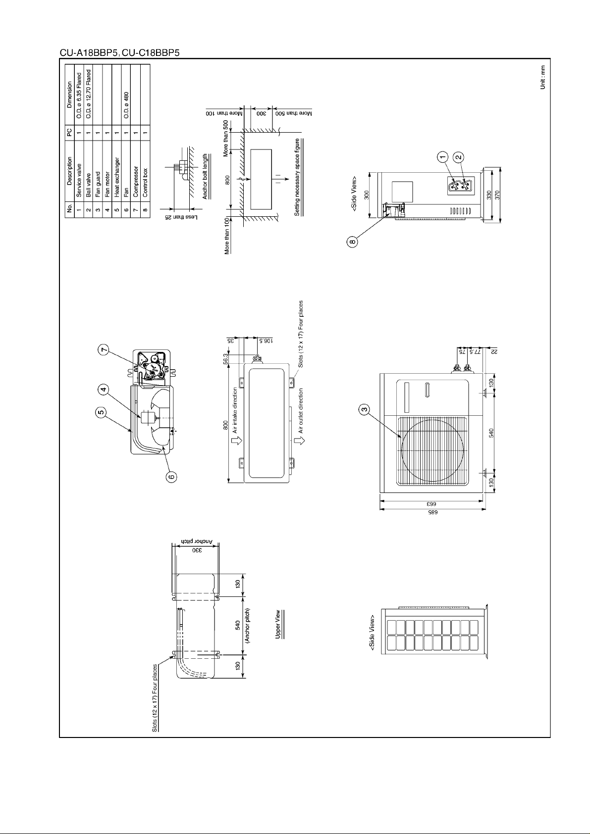
11
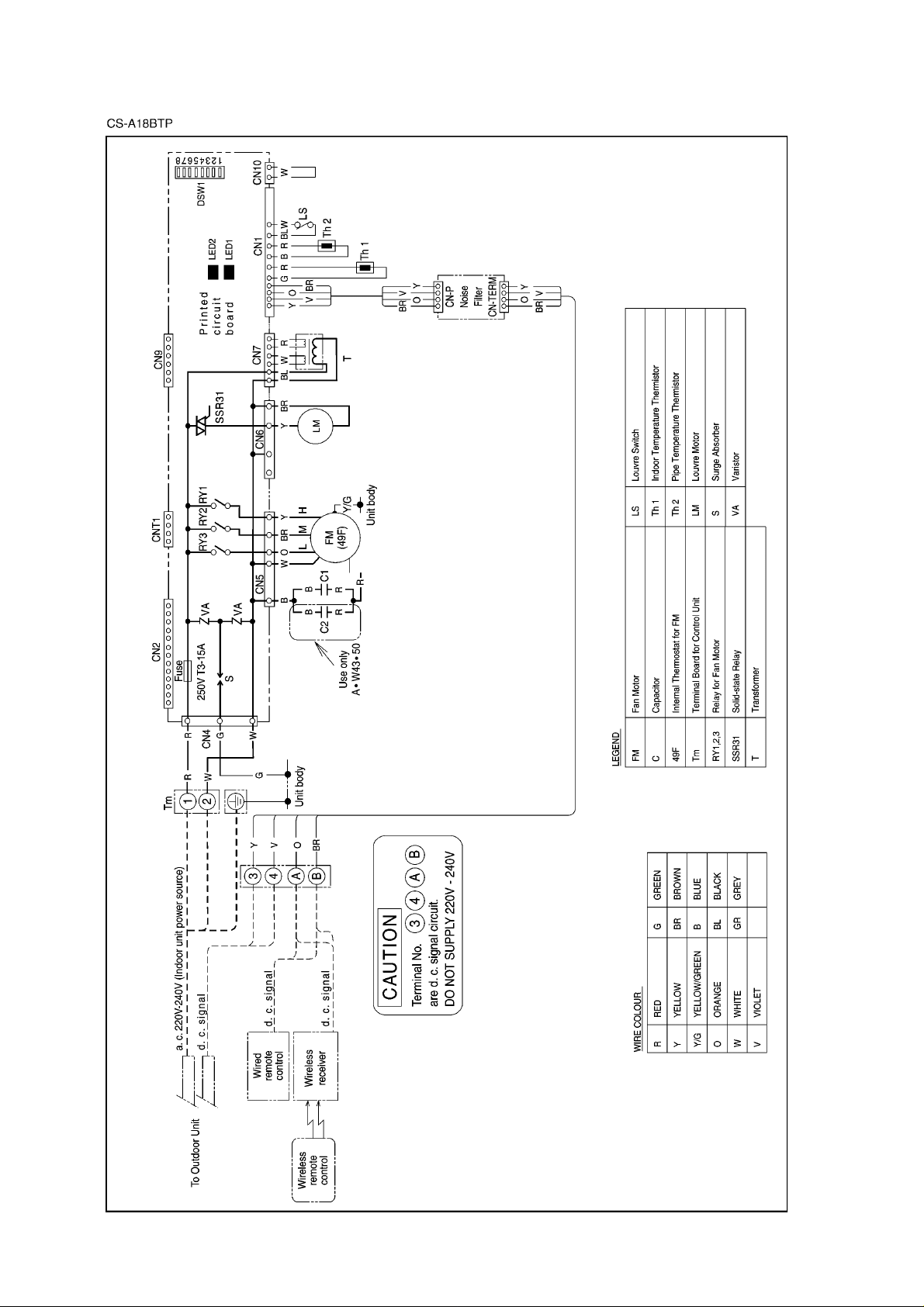
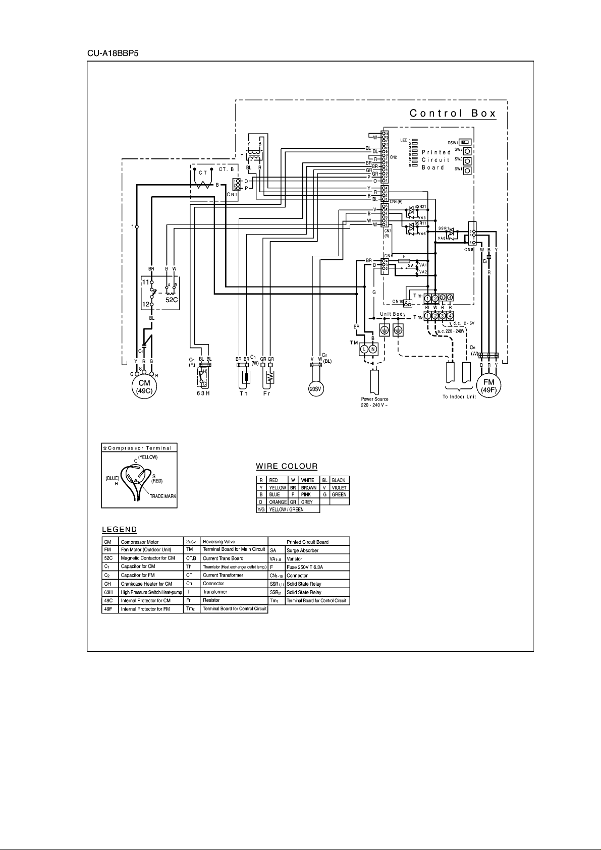
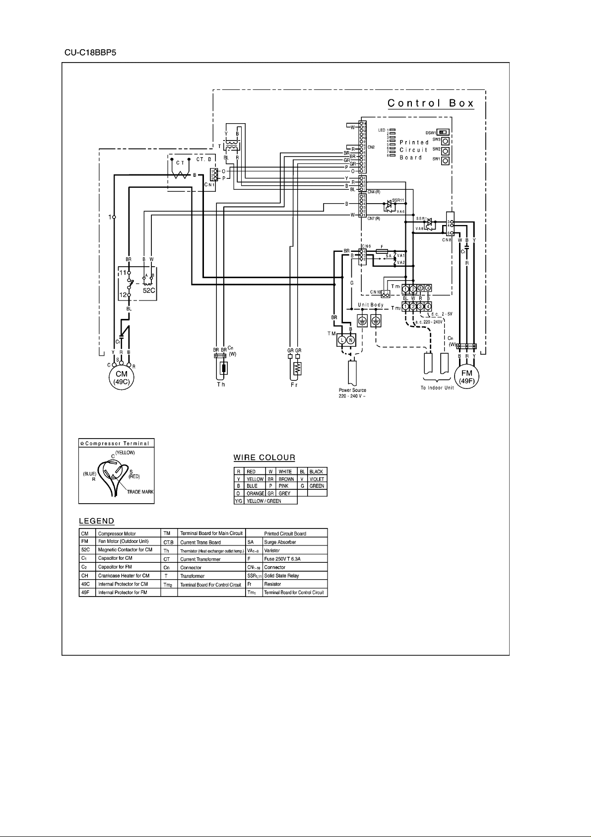
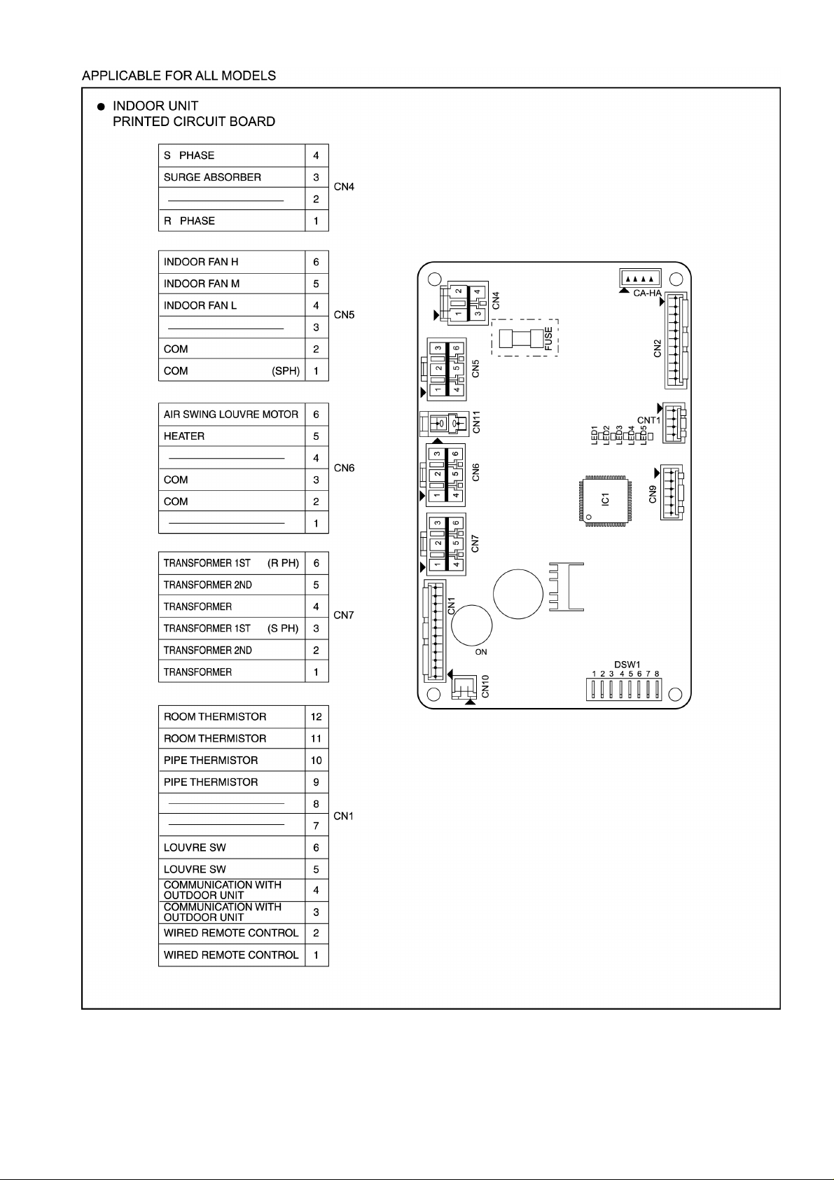
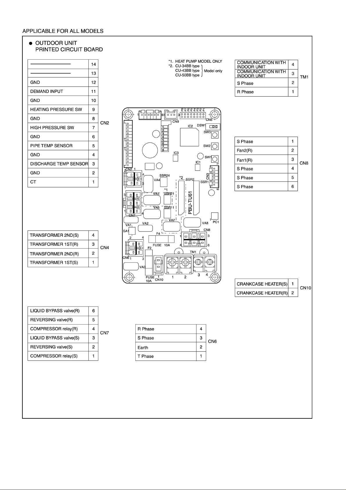
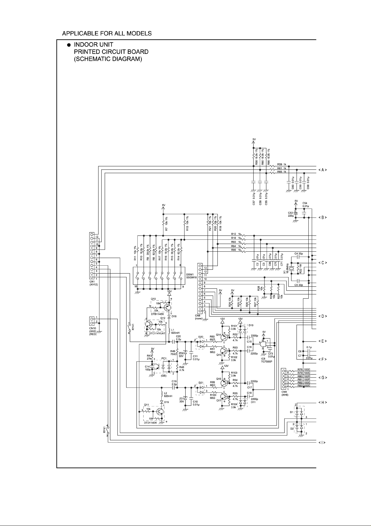
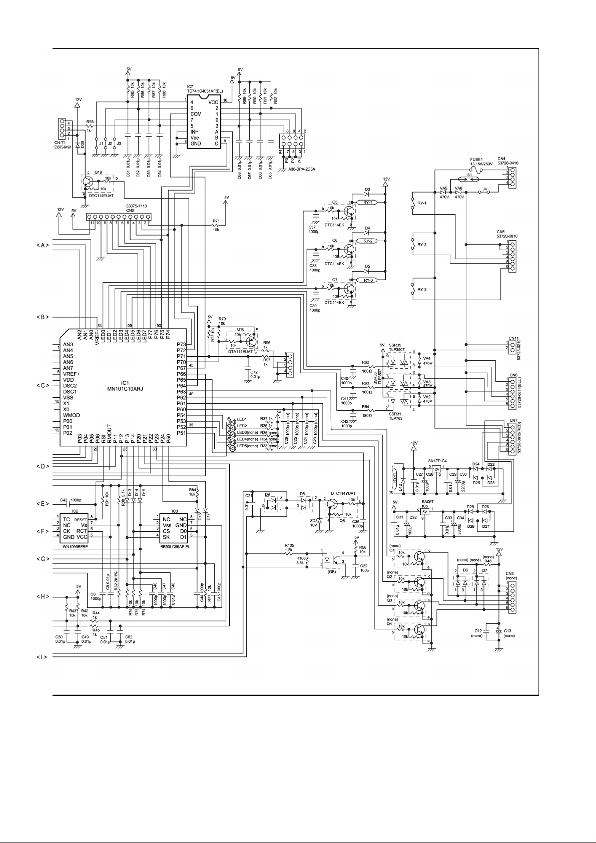
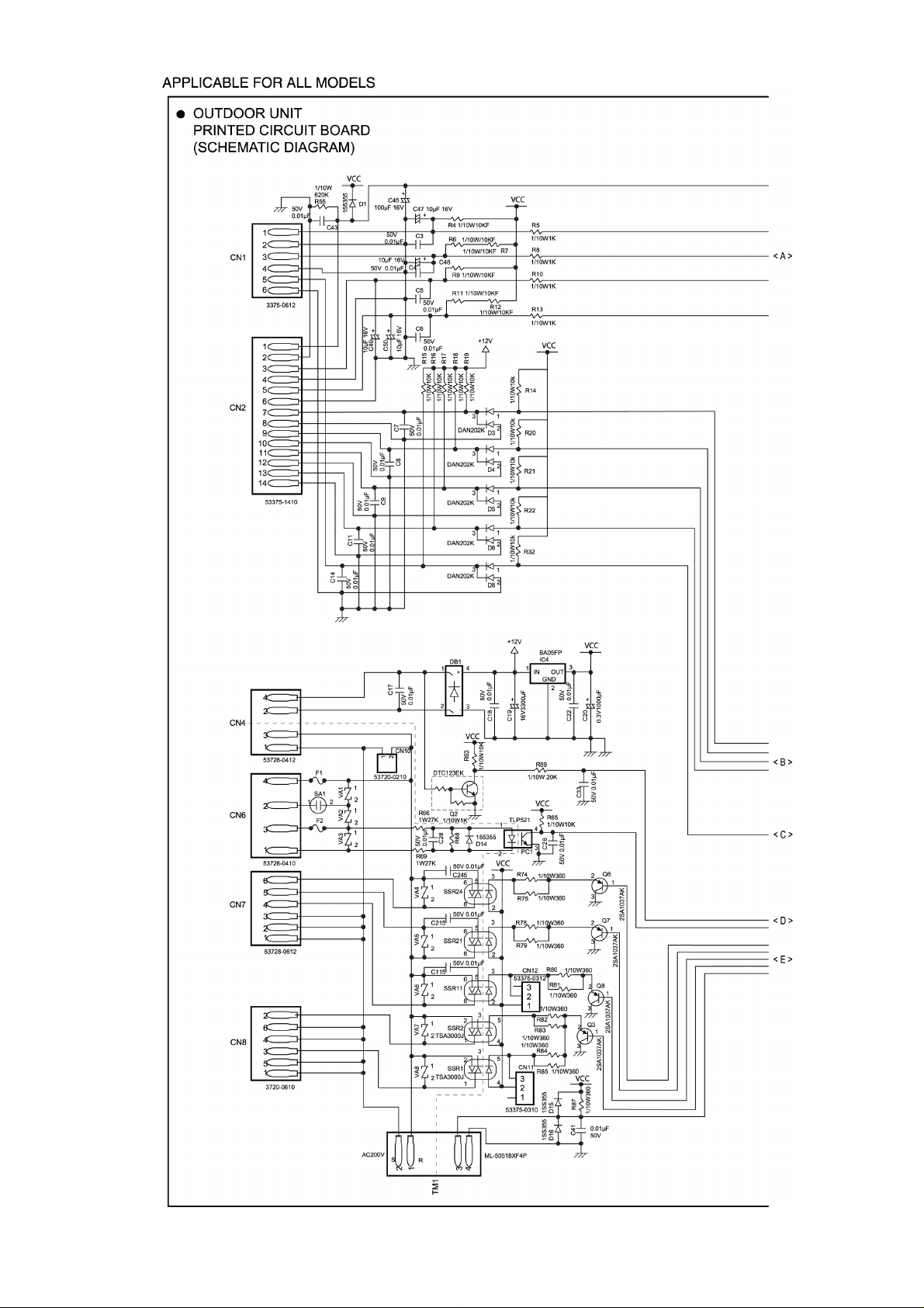
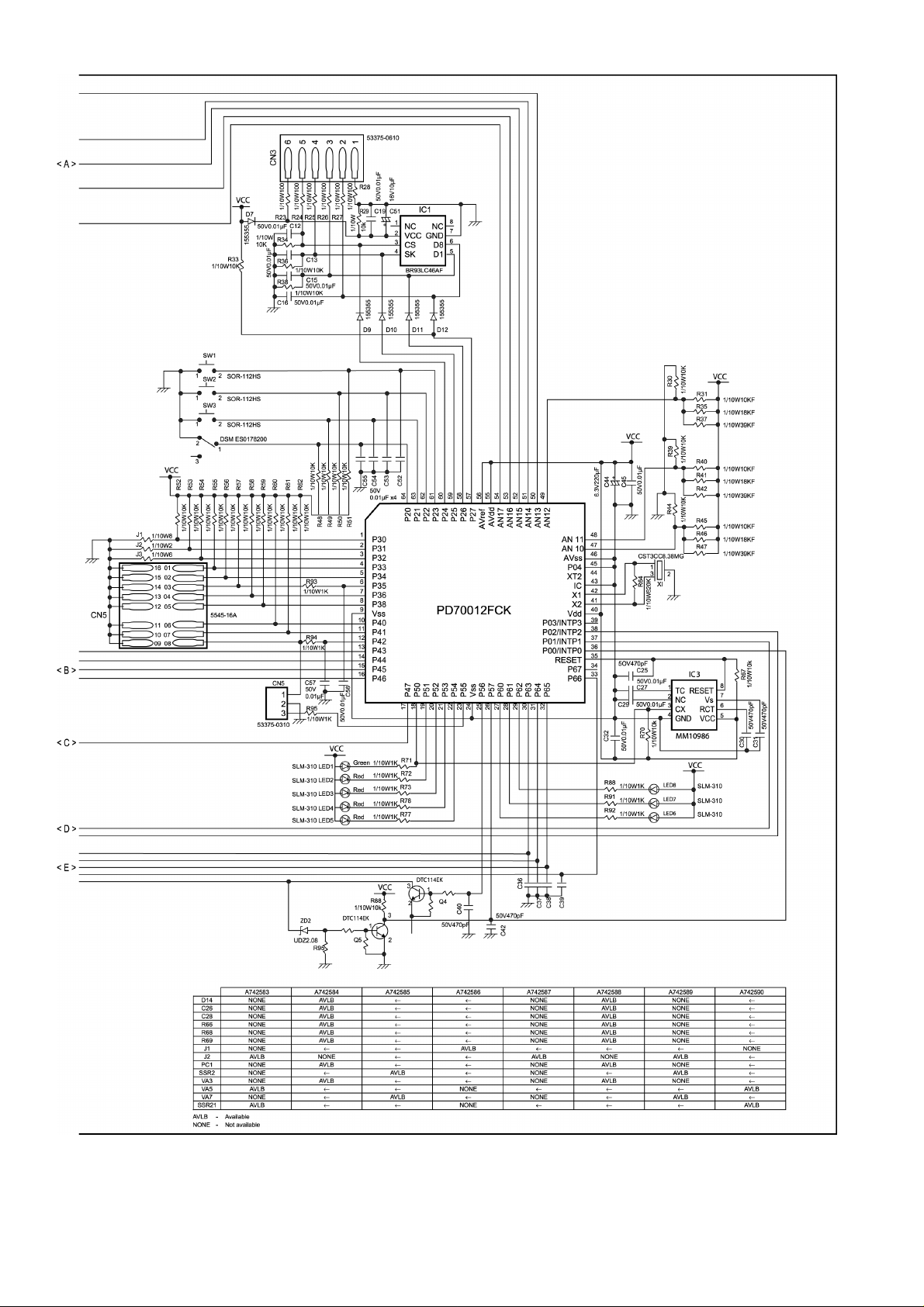
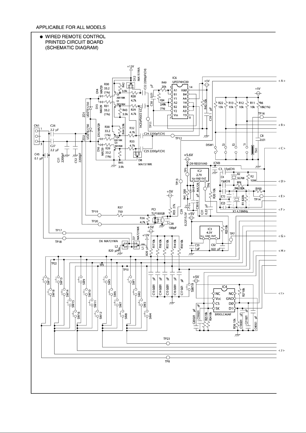
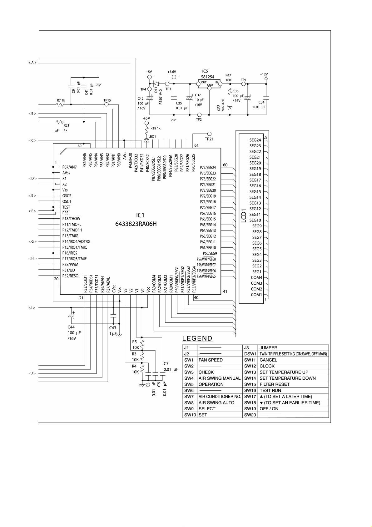
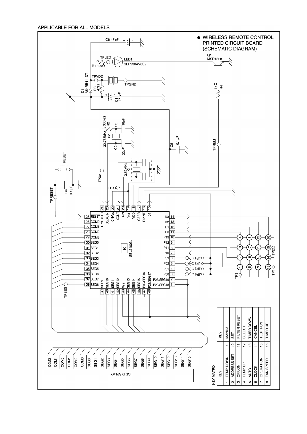
6 CIRCUIT DIAGRAM
1213141516171819202122
23
7 OPERATING INSTRUCTION
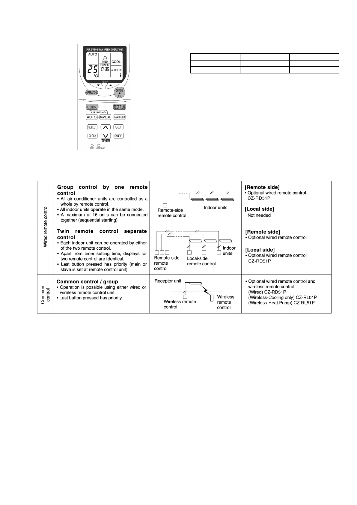
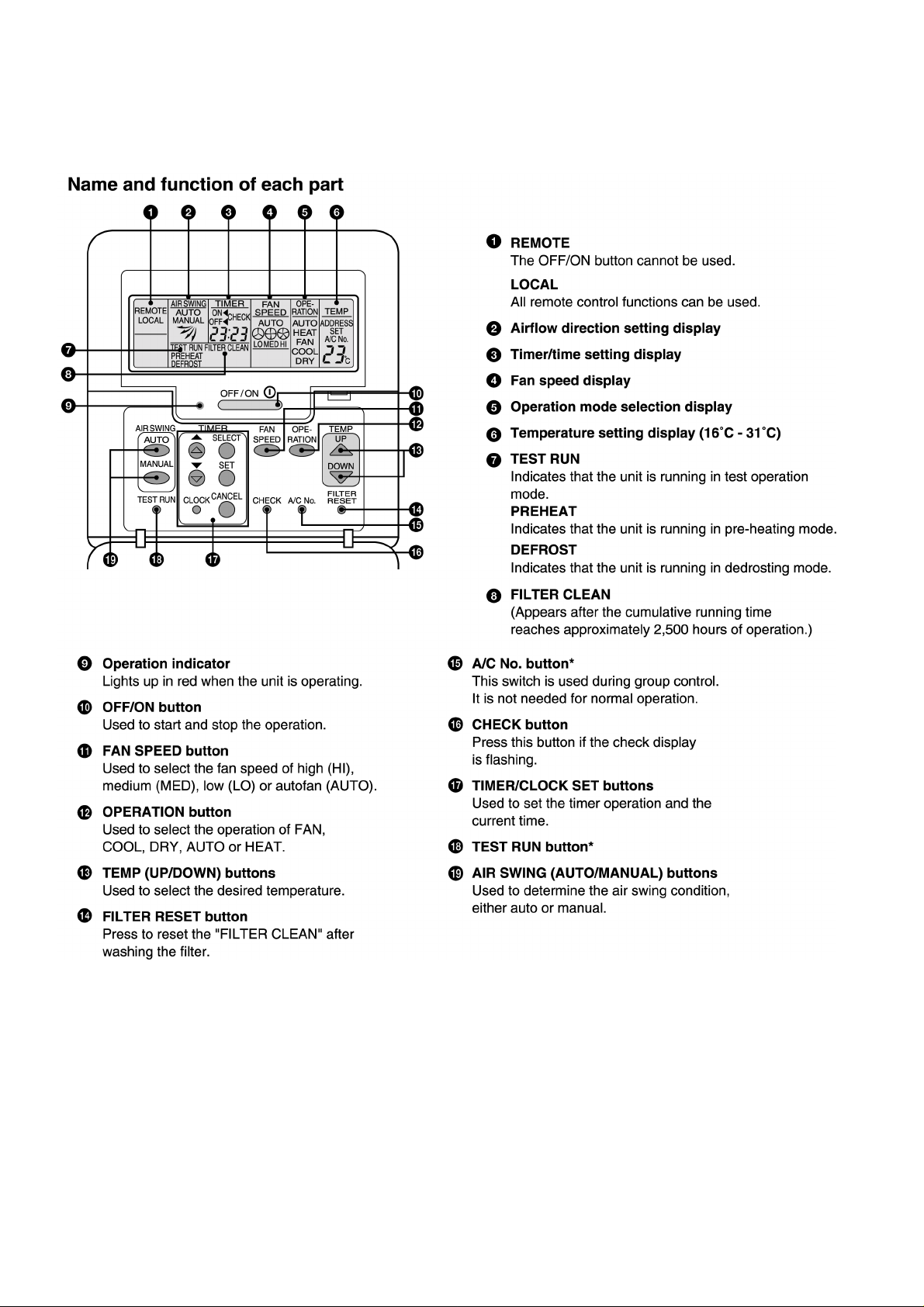
7.1. Wired Remote Control (OPTIONAL PARTS)
NOTES:
•
• Ensure that the correct button is pressed as simultaneous pressing of the multiple buttons will not make the setting correct.
• •
•
• The illustration above is for explanatory purposes only. The appearance will be different during actual operation.
• •
•
• Do not operate the remote control with wet hands. Otherwise, electric shock or malfunction may occur.
• •
•
• Do not press the remote control buttons with sharp object as this may damage the remote control.
• •
•
• Buttons marked with * are not needed for normal operation. If one of these buttons is pressed by mistake, press the same
• •
button once more to cancel the operation.
•
• When the power resumed after power failure, the unit will restart automatically with all the previous settings preserved by the
• •
memory function. (Auto restart function)
24
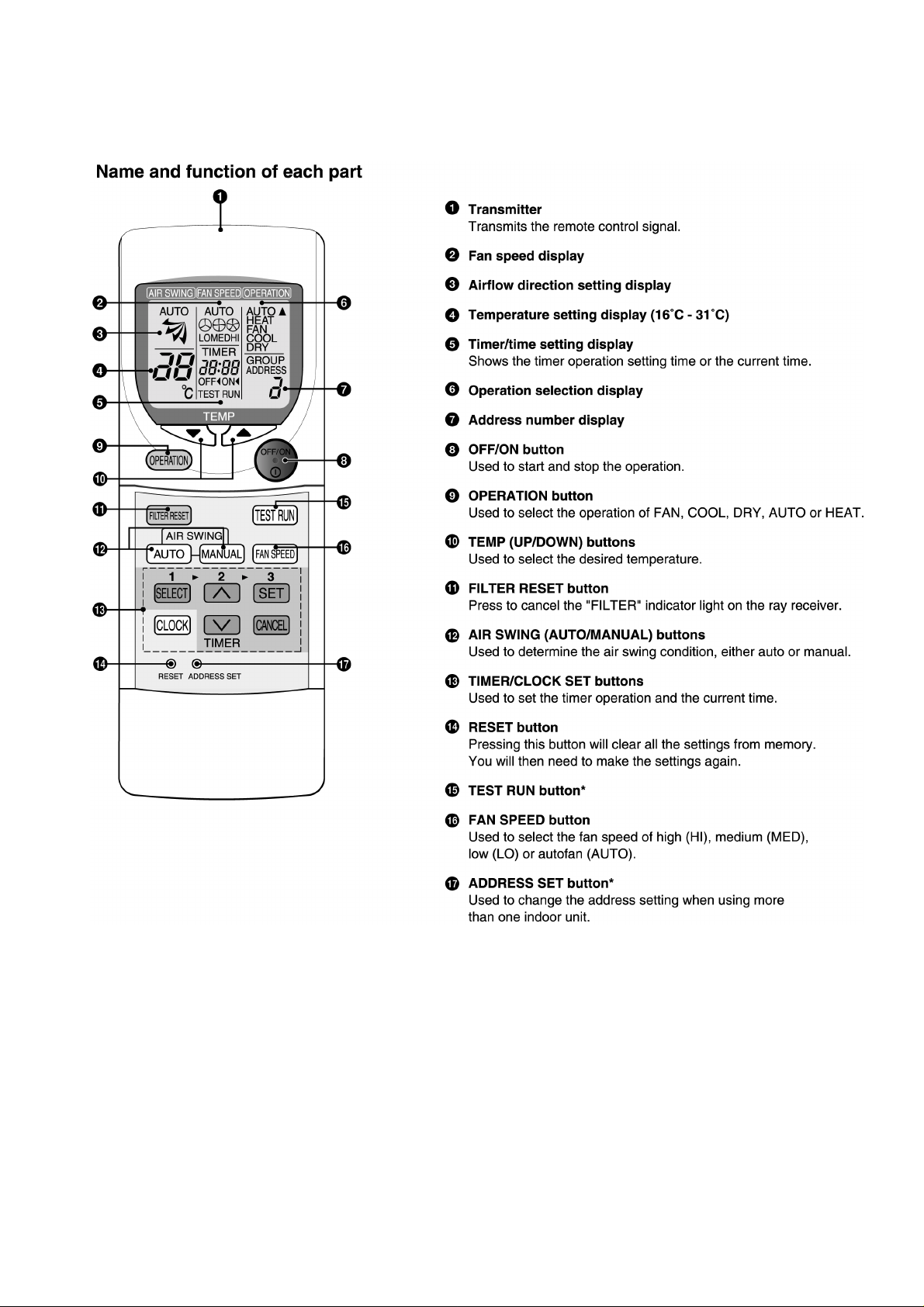
7.2. Wireless Remote Control (OPTIONAL PARTS)
NOTES:
•
• Ensure that the correct button is pressed as simultaneous pressing of the multiple buttons will not make the setting correct.
• •
•
• The illustration above is for explanatory purpose only. The appearance will be different during actual operation.
• •
•
• If using the wireless remote control in conjunction with the wired remote control, the settings made from the wireless remote
• •
control will appear on the wired remote control display (except when making timer settings).
•
• Buttons marked with * are not needed for normal operation. If one of these buttons is pressed by mistake, press the same
• •
button once more to cancel the operation.
•
• When the power resumed after power failure, the unit will restart automatically with all previous settings preserved by the
• •
memory function. (Auto restart function)
25
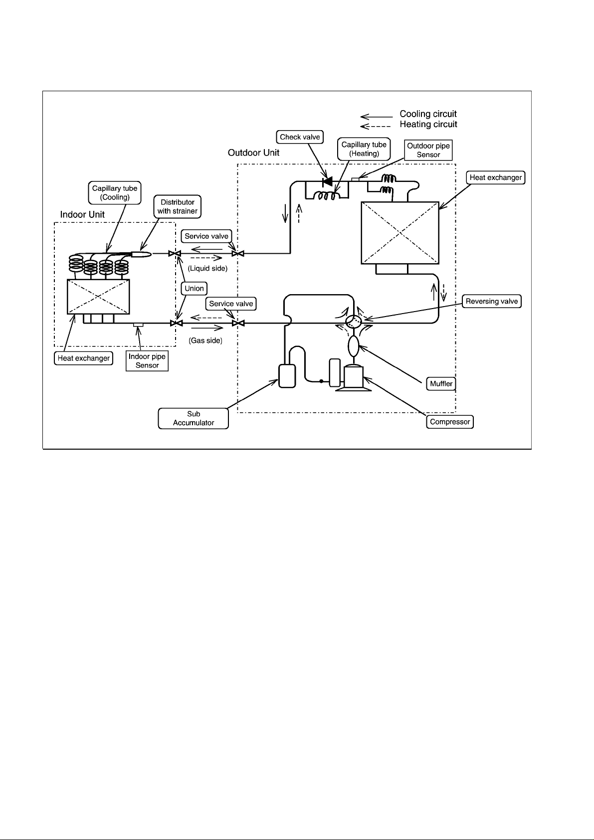
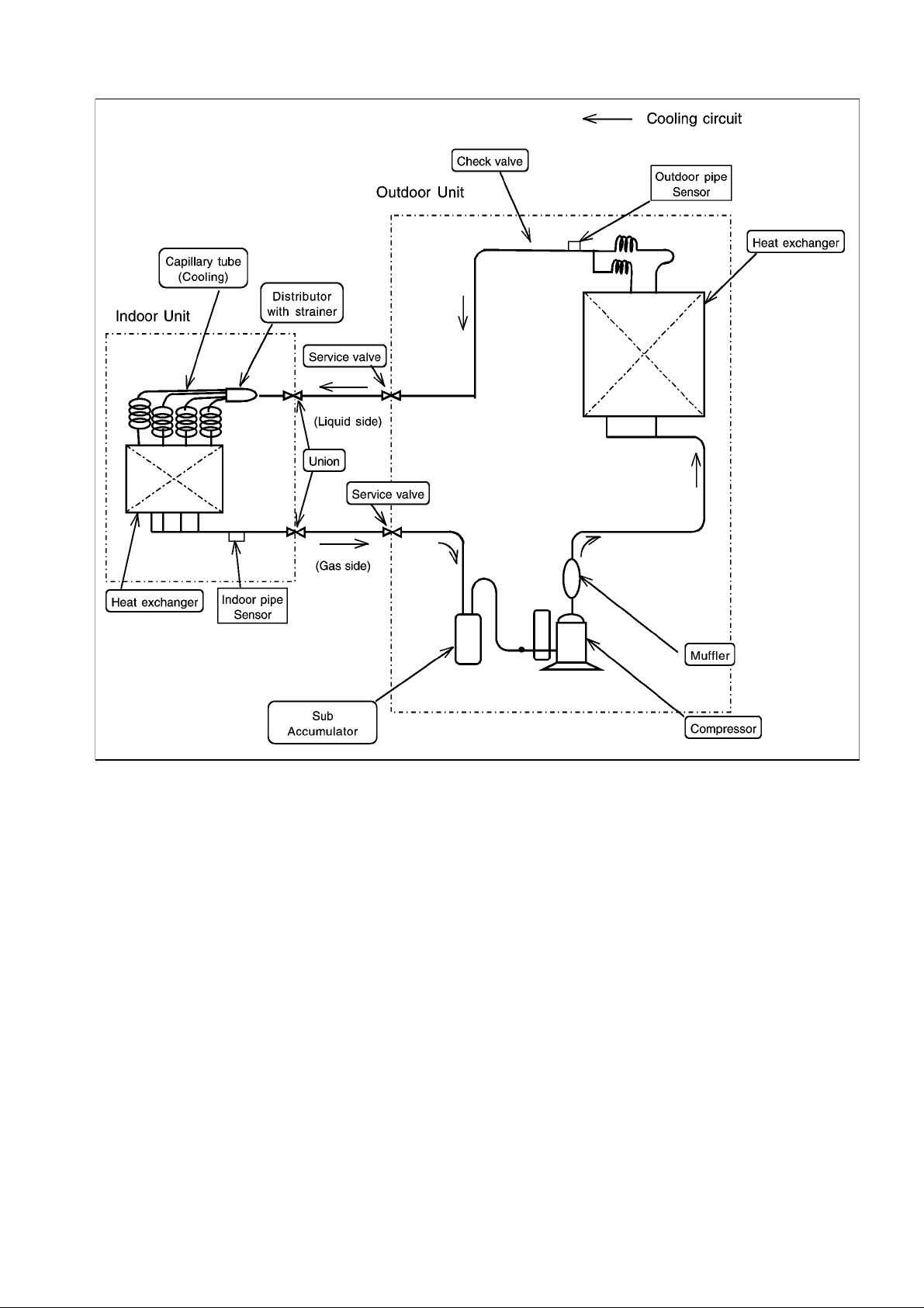
8 REFRIGERATION CYCLE
CS-A18BTP/CU-A18BBP5
26
CS-A18BTP/CU-C18BBP5
27
9 OPERATION RANGE
Power Supply
The applicable voltage range for each unit is given in the following table. The working voltage among the three phases must be
balanced within a 3% deviation from each voltage at the compressor terminals. The starting voltage must be higher than 85% of
the rated voltage.
Power Supply
MODEL Unit Main Power Applicable Voltage
Phase, Volts Hz Max Min
A18BB 1~220 50 242 198
1~230 50 253 207
1~240 50 264 216
Indoor and Outdoor Temperature
•
• Cooling only type
• •
Model 50Hz CU-C18BBP5
Operating Hz Indoor Temp. (D.B./W.B.) (°C) Outdoor Temp. (D.B./W.B.) (°C)
Max Min Max Min
Cooling 50/60 32/23 21/15 43/- -5/-
•
• Heat pump type
• •
Model 50Hz CU-A18BBP5
Operating Hz Indoor Temp. (D.B./W.B.) (°C) Outdoor Temp. (D.B./W.B.) (°C)
Cooling 50 32/23 21/15 43/- -5/Heating 50 27/- 16/- 24/18 -10/-
Max Min Max Min
28
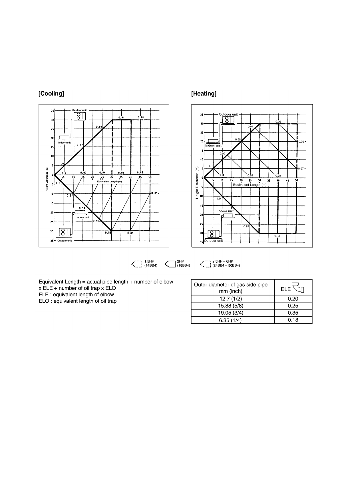
10 PIPE LENGTH
CORRECTION OF COOLING CAPACITY AND HEATING CAPACITIES
■■■■
Correction of cooling and heating capacities according to the connecting pipe length.
The data of cooling capacities (marked on the name plate) are based on 5 meters connecting pipe and horizontal installation.
For other pipe length of other installation multiply by the following correction factor to determine the revised cooling capacity.
REFRIGERANT ADDITIONAL CHARGE
■■■■
Piping installation by standard piping
1.
•
• At the time of shipment from the factory, this unit is charged with enough refrigerant for an equivalent pipe length of 10m.
• •
(Refer to the following table)
But when the piping length exceeds 10m, additional charge is required according to the following table.
Example:
CU-C18BBP5
In case of 11m long pipe (one way), the amount of refrigerant to be replenished is: (11 - 10) x 20 = 20g
29
■ Cooling only type
Model Name Standard piping specification
Liquid piping (dia.mm) Gas piping (dia.mm) Gas charge-less length
(m)
CU-C18BBP5 6.35 12.70 10 20
Additional gas volume
(g/m)
■ Heat pump type
Model Name Standard piping specification
Liquid piping (dia.mm) Gas piping (dia.mm) Gas charge-less length
CU-A18BBP5 6.35 12.70 10 20
Piping installation by existing piping
2.
(m)
Additional gas volume
(g/m)
The above models change the liquid pipe size of the previous series. It is to use the existing piping by adjusting the refrigerant
gas volume.
Please do correct piping installation referring to the above table.
Attention
•
•
Please do not decrease the gas piping size. (It causes the breakdown of the compressor).
• •
•
•
The equivalent piping length and the cooling and heating capacity change rate are same as the standard piping specification.
• •
30
 Loading...