

Panasonic CT-36D20 Owner’s Manual
Panasonlc
Color Television
Operating Instructions
CT-27D20 CT-32D20
CT-27D20U CT-32D20U
CT-36D20
CT-36D20U
For assistance, please call: 1-800-211-PANA (7262) or
send e-mail to: consumerproducta@panasonic.com (USA only)
ISSUE 0
TQB2AA0332
PRINTED IN USA
00308

WARNING
WARNING: To reduce the risk of electdc shock do not remove cover or back.
No user-servlceable parts inside. Refer servicing toqualified service personnel.
The lightning flash with arrow
head within a triangle is
intended to tell the user that
parts inside the product are a
risk of electric shock to persons.
WARNING: To preventfireor shockhazard,do notexposethisappliance
to rainor moisture.
The exclamation point within a
triangle is intended to tell the
user that important opera_ng
and servicing instructions are in
the papers with the appliance.
=el
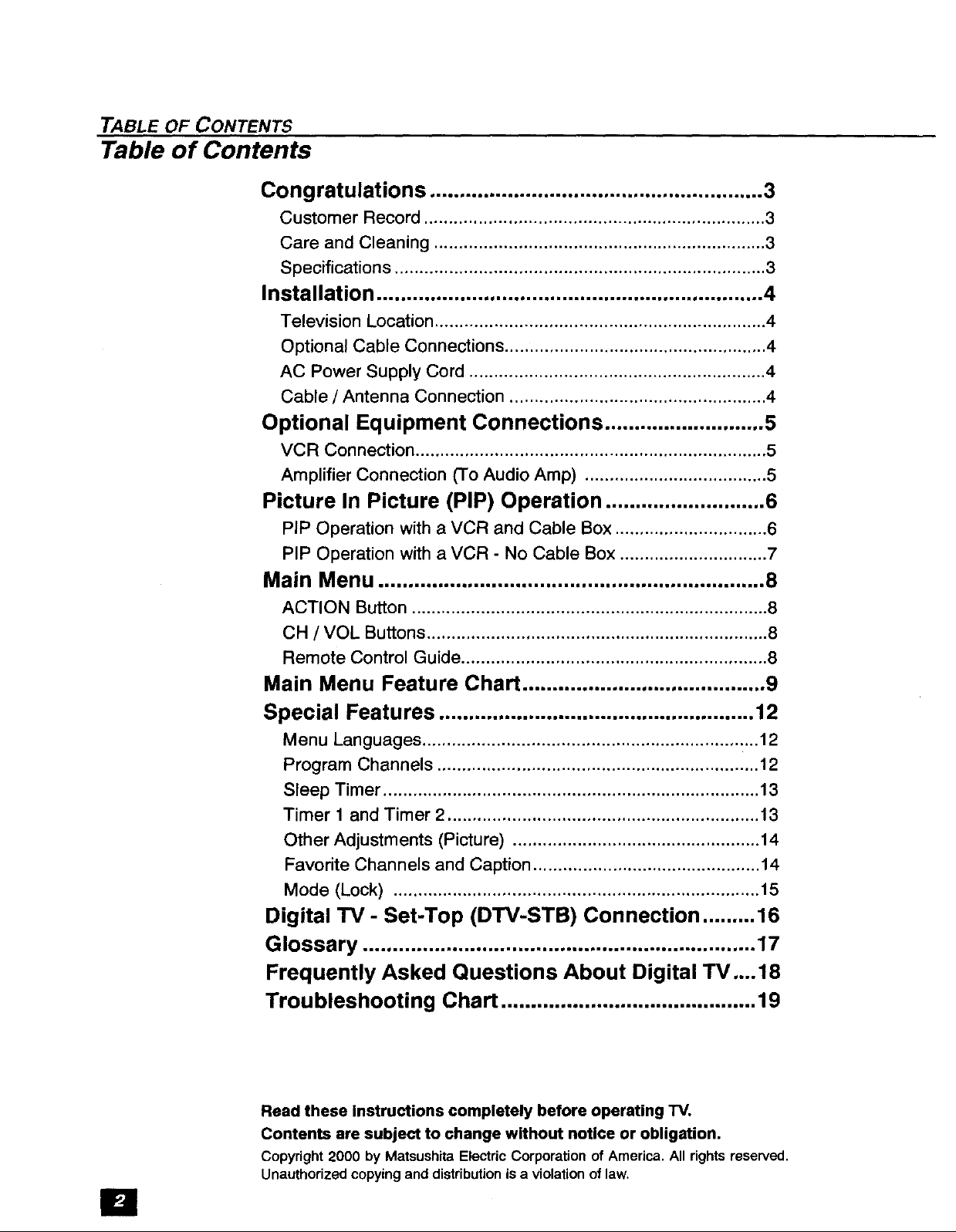
TABLE OF CONTENTS
Table of Contents
Congratulations ........................................................ 3
Customer Record ..................................................................... 3
Care and Cleaning ................................................................... 3
Specifications ........................................................................... 3
Installation ................................................................. 4
Television Location ................................................................... 4
Optional Cable Connections ..................................................... 4
AC Power Supply Cord ............................................................ 4
Cable / Antenna Connection .................................................... 4
Optional Equipment Connections ........................... 5
VCR Connection ....................................................................... 5
Amplifier Connection (To Audio Amp) ..................................... 5
Picture In Picture (PIP) Operation ........................... 6
PIP Operation with a VCR and Cable Box ............................... 6
PIP Operation with a VCR - No Cable Box .............................. 7
Main Menu ................................................................. 8
ACTION Button ........................................................................ 8
CH / VOL Buttons ..................................................................... 8
Remote Control Guide .............................................................. 8
Main Menu Feature Chart ......................................... 9
Special Features ..................................................... 12
Menu Languages .................................................................... 12
Program Channels ................................................................. 12
Sleep Timer ............................................................................ 13
Timer 1 and Timer 2 ............................................................... 13
Other Adjustments (Picture) .................................................. 14
Favorite Channels and Caption .............................................. 14
Mode (Lock) .......................................................................... 15
Digital rv- Set-Top (DTV-STB) Connection ......... 16
Glossary .................................................................. 17
Frequently Asked Questions About Digital TV....18
Troubleshooting Chart ........................................... 19
Read these Instructions completely before operating "IV.
Contents are subject to change without notice or obligation.
Copyright2000 by MatsushitaElectric Corporationof America,All rightsreserved,
Unauthorizedcopyingand distributionisa violationof law.
3ongratulations
Your new "IV features a solid state chassis that is designed to give you many years of
enjoyment. It was thoroughly tested and tuned at the factory for best performance.
3ustomer Record
The model and serial number of this product are located on the back of the "IV. You
should note the model and serial number-in the space provided and retain as a
permanent record of your purchase. This will aid inidentification inthe event of theft or
loss. Product registraton for U.S. customers is available at: www.prodreg.com/
panasonic,
.3are and Cleaning
CONGRA TULA TIONS
Model
Number
Serial
Number
Screen (Turn TV Off)
D Use a mild soap solution or window cleaner with a soft clean cloth. DO NOT USE
ABRASIVE CLEANERS.
t-I Avoidexcessive moistureandwipe dry.
Note: Do not spray any type of cleaning fluid directly on the screen.
Cabinet and Remote Control
r-i For cabinetsand remotecontrol,use a softclothdampened withwater or a milddetergent
solution. Avoidexcessivemoistureand wipe dry.
[] Do notuse benzene,thinneror otherpetroleum basedproducts.
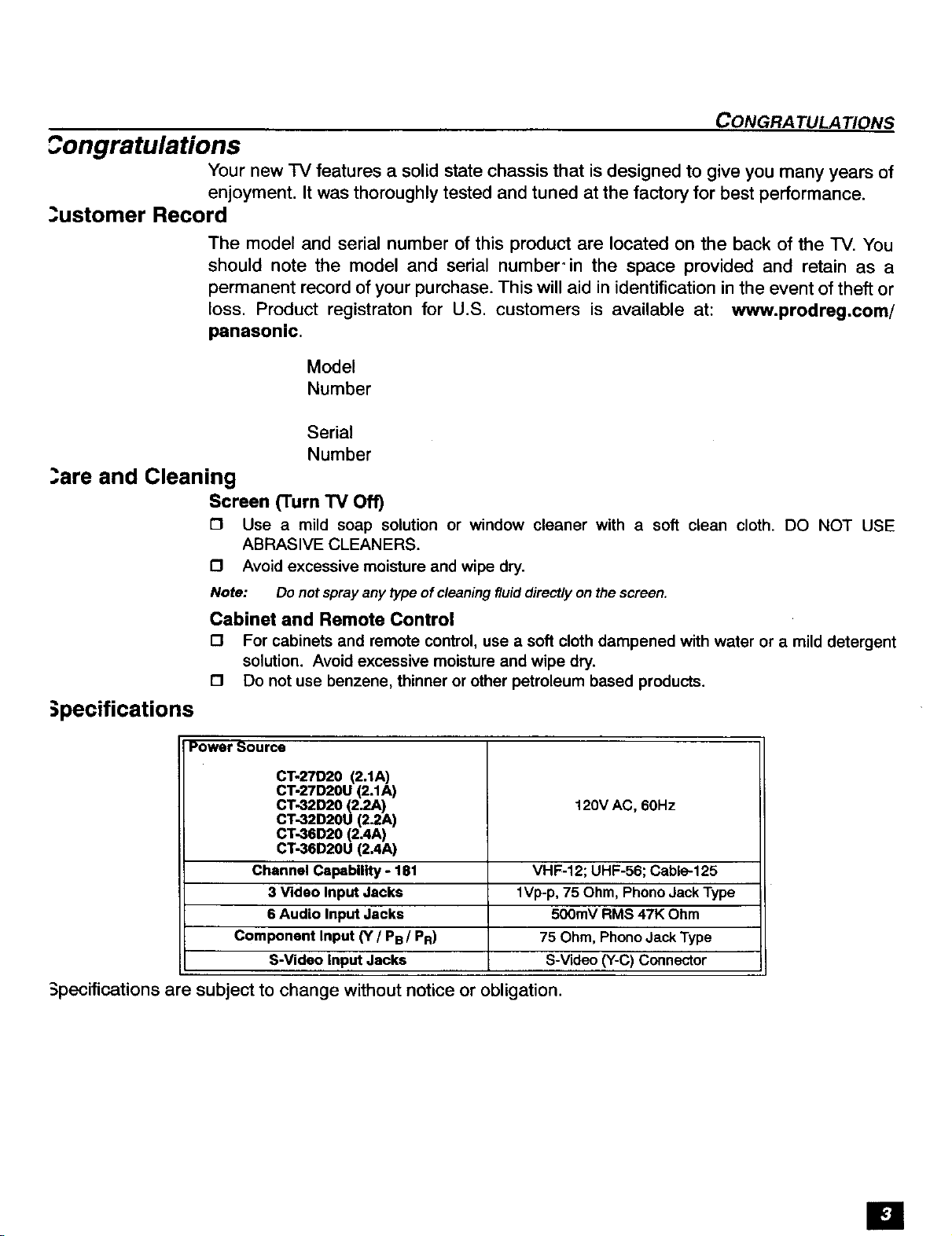
;pecifications
Power Source
CT-27D20 (2.1A)
CT-27D20U (2.1A)
CT-32D20 (2.2A) 120V AC, 60Hz
CT-32D20U (2.2A)
CT-36D20 (2.4A)
CT-36D20U (2AA)
Channel Capability - 181 VHF-12; UHF-56; Cable-125
3 Video Input Jacks 1Vp-p, 75 Ohm, Phono Jack Type
6 Audio Input Jacks 500mV RMS 47K Ohm
Component Input (Y / PB / PR) 75 Ohm, Phono Jack Type
S-Video Input Jacks S-Video (Y-C) Connector
Specifications are subject to change without notice or obligation.
IEi

INSTALLATION
Installation
Television Location
This unit is intended to be used with an optional stand or entertainment center.
Consult your dealer for available options.
E3 Avoid excessive sunlight or bright lights, including reflections.
I_ Keep away from excessive heat or moisture. Inadequate ventilation may cause internal
component failure.
E3 Fluorescent lighting may reduce remote control transmitting range.
E3 Keep away from magnetic equipment, including motors, fans and external speakers.
Optional Cable Connections
Shielded audio and video cables should be used between components. For best
results:
El Use 75-ohm coaxial shielded cables.
1_ Use appropriate input and output connectors, that match your component connectors.
I_ Avoid long cables to minimize interference.
AC Power Supply Cord
CAUTION: TO PREVENT ELECTRIC SHOCK MATCH WIDE BLADE OF PLUG TO
WIDE SLOT OF AC OUTLET AND FULLY INSERT. DO NOT USE A PLUG WITH A
RECEPTACLE OR OTHER OUTLET UNLESS THE BLADE CAN BE FULLY
INSERTED TO PREVENT BLADE EXPOSURE. FOR SOME MODELS THAT ARE
NON-POLARIZED, THE USE OF AN AC ADAPTOR CONNECTOR MAY
BE NECESSARY.
Polarized plug
,llI
Non-Polarized plug
Cable / Antenna Connection
For proper reception, either a cable or antenna connection is required.
Cable Connection
Connect the cable supplied by your local cable company.
Note: A cable converter box may be required for proper reception. Check with
your local cable company for compatibility requirements.
Antenna Connections
t'l For proper reception of VHF/UHF channels, an external antenna is
required. For best reception an outdoor antenna is recommended.
D Antenna Mode must be set to IV.
Incoming Cable from
Cable Company
75 Ohm VHF/UHF
on back of TV
Incoming Cable from
Home Antenna
--_ Cable Preset
Cable Mode is preset at the factory. Antenna I
users must change to Antenna Mode in the
Setup Menu,
Iii
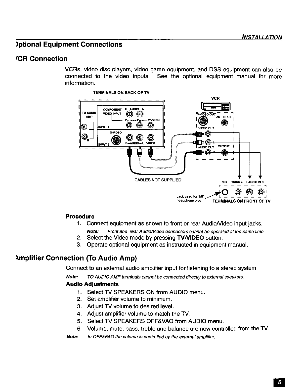
)ptional Equipment Connections
fCR Connection
VCRs, video disc players, video game equipment, and DSS equipment can also be
connected to the video inputs. See the optional equipment manual for more
information.
TERMINALS ON BACK OF TV
INSTALLATION
VCR
TO AUO
AMP
_L m
COMPONENT R--AUDIIC-- L
v_o._ _) _ _v,_O_T
I,_ P. __Ps__Y/VIDEO I _)
,..=, _®0 'v,oEoooT
ANT INPUT I
t- rO-J ! ,'%']TTO--oT
I _ J :i I =" "
%
CABLES NOT SUPPLIED Hpj VIOE O 3 L AUDI O IN R
.,., i,,,.j, ®
headphoneplug TERMINALS ON FRONT OF TV
Procedure
1. Connect equipment as shown to front or rear AudioNideo input jacks.
Note: Front and rear Audio/Video connectors cannot be operated at the same time.
2. Select the Video mode by pressing TVNIDEO button.
3. Operate optional equipment as instructed in equipment manual.
r 1
_,mplifier Connection (To Audio Amp)
Connect to an external audio amplifier input for listening to a stereo system.
Note: TO AUDIO AMP terminals cannot be connected directly to external speakers.
Audio Adjustments
1. Select TV SPEAKERS ON from AUDIO menu.
2. Set amplifier volume to minimum.
3. Adjust TV volume to desired level.
4. Adjust amplifier volume to match the TV.
5. Select TV SPEAKERS OFF&VAO from AUDIO menu.
6. Volume, mute, bass, treble and balance are now controlled from the TV.
Note: In OFF&FAO the volume is controlled by the external amplifier.
!i

PICTURE IN PICTURE (PIP) OPERATION
Picture In Picture (PIP) Operation
PIP Operation with a VCR and Cable Box
This television includes a Picture In Picture (PIP) feature. A second video source
(VCR, Camcorder, etc.) is required to provide a second picture.
Connect your television to a VCR and'Cable Box, as shown.
TERMINALS ON BACK OF TV
COMPONENT R--AUDIO-- L
TO AUDIAMP VIDEOINPUT _ ®
; L_ PR __PB__Y/VIDEO
I_L_ INPUT 1 _) _
CABLES NOT SUPPLIED
Note: The Remote Control must be programmed with suppfied codes to operate the VCR and Cable
Box. See Programming the Remote Control in the Remote Control Quick Reference Guide,
VCR CABLE BOX
I(_) _T_'mUT I
Iv'_°°uT ' I I
'AUDIOOUT OUI]PUT I I ANTINPUT I
Cable splitter
(Not supplied)
Incoming cable
Procedure
Press the PIP button on the Remote Control to display the PIP frame.
Note: The PIP picture is the same as the main picture, initially.
E1
To view a different picture in the PIP frame:
[3 Press the W/VIDEO button on the Remote Control to select the video PIP source.
[3 Verify the CABLE BOX and VCR are ON and the VCR is tuned to channel 3,
£3 Choose channels for the PIP frame by pressing the CBL button on the Remote Control and
using the numeric keypad or CH up/down buttons,
£3 Choose channels for the Main Picture by pressing the TV button on the Remote Control
and using the numeric keypad or CH up/down buttons.
.__/__ SWAP Button
The SWAP button switches the PIP and Main
Picture source. Press the RECALL button for on
screen PIP and Main Picture source status.
 Loading...