

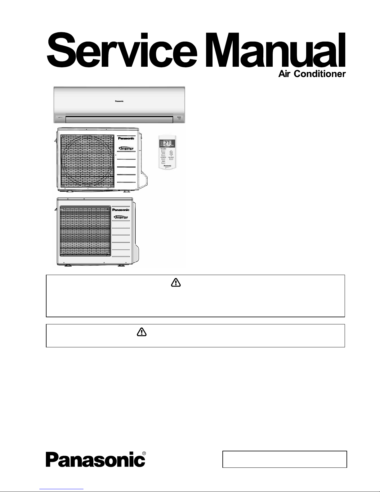
Panasonic CS-YE18NKV-6, CS-YE24NKV-6, CU-YE18NKV-6, CU-YE24NKV-6 Service Manual
© Panasonic Appliances Air-Conditioning Malaysia Sdn.
Bhd. 2012. Unauthorized copying and distribution is a
violation of law.
Order No: PHAAM1201029C3
Indoor Unit Outdoor Unit
CS-YE18NKV-6
CS-YE24NKV-6
CU-YE18NKV-6
CU-YE24NKV-6
TABLE OF CONTENTS
PAGE PAGE
1. Safety Precautions.............................................3
2. Specifications.....................................................5
3. Features ..............................................................8
4. Location of Controls and Components ...........9
4.1 Indoor Unit......................................................9
4.2 Outdoor Unit................................................... 9
4.3 Remote Control..............................................9
5. Dimensions.......................................................10
5.1 Indoor Unit & Remote Control...................... 10
5.2 Outdoor Unit................................................. 11
6. Refrigeration Cycle Diagram........................... 13
7. Block Diagram ..................................................14
7.1 CS-YE18NKV-6 CU-YE18NKV-6.................14
7.2 CS-YE24NKV-6 CU-YE24NKV-6.................15
8. Wiring Connection Diagram............................16
8.1 Indoor Unit....................................................16
WARNING
This service information is designed for experienced repair technicians only and is not designed for use by the general public.
It does not contain warnings or cautions to advise non-technical individuals of potential dangers in attempting to service a product.
Products powered by electricity should be serviced or repaired only by experienced professional technicians. Any attempt to
service or repair the product or products dealt with in this service information by anyone else could result in serious injury or death.
PRECAUTION OF LOW TEMPERATURE
In order to avoid frostbite, be assured of no refrigerant leakage during the installation or repairing of refrigerant circuit.

2
8.2
Outdoor Unit .................................................17
9. Electronic Circuit Diagram ..............................19
9.1 Indoor Unit....................................................19
9.2 Outdoor Unit .................................................20
10. Printed Circuit Board .......................................22
10.1 Indoor Unit ....................................................22
10.2 Outdoor Unit .................................................24
11. Installation Instruction.....................................27
11.1 Select the Best Location...............................27
11.2 Indoor Unit ....................................................28
11.3 Outdoor Unit .................................................32
12. Operation and Control .....................................35
12.1 Basic Function ..............................................35
12.2 Airflow Direction............................................37
12.3 Timer Control ................................................39
12.4 Auto Restart Control .....................................39
13. Protection Control ............................................40
13.1 Protection Control for All Operations ............40
13.2 Protection Control for Cooling Operation .....42
13.3 Protection Control for Heating Operation .....43
14. Servicing Mode .................................................44
14.1 Auto OFF/ON Button ....................................44
14.2 Remote Control Number switch ...................44
15. Troubleshooting Guide ....................................45
15.1 Refrigeration Cycle System ..........................45
15.2 Relationship Between The Condition Of
The Air Conditioner And Pressure And
Electric Current.............................................46
15.3 Breakdown Self Diagnosis Function.............47
15.4 Error Code Table ..........................................49
15.5 Troubleshooting Flowchart ...........................50
16. Disassembly and Assembly Instructions ......73
16.1 Small Air Filter, Indoor Electronic
Controllers and Control Board Removal
Procedures ...................................................73
16.2 To Remove Cross Flow Fan and Indoor
Fan Motor .....................................................76
17. Technical Data ..................................................78
17.1 Operation Characteristics .............................78
18. Exploded View and Replacement Parts
List .....................................................................86
18.1 Indoor Unit ....................................................86
18.2 Outdoor Unit .................................................89
3
CAUTION
WARNING
WARNING
1. Safety Precautions
Read the following “SAFETY PRECAUTIONS” carefully before perform any servicing.
Electrical work must be installed or serviced by a licensed electrician. Be sure to use the correct rating of the
power plug and main circuit for the model installed.
The caution items stated here must be followed because these important contents are related to safety. The
meaning of each indication used is as below. Incorrect installation or servicing due to ignoring of the instruction
will cause harm or damage, and the seriousness is classified by the following indications.
This indication shows the possibility of causing death or serious injury.
This indication shows the possibility of causing injury or damage to properties.
The items to be followed are classified by the symbols:
Carry out test run to confirm that no abnormality occurs after the servicing. Then, explain to user the operation,
care and maintenance as stated in instructions. Please remind the customer to keep the operating instructions for
future reference.
1. Do not modify the machine, part, material during repairing service.
2. If wiring unit is supplied as repairing part, do not repair or connect the wire even only partial wire break. Exchange the whole wiring unit.
3. Do not wrench the fasten terminal. Pull it out or insert it straightly.
4. Engage dealer or specialist for installation and servicing. If installation of servicing done by the user is defective, it will cause water leakage,
electrical shock or fire.
5. Install according to this installation instructions strictly. If installation is defective, it will cause water leakage, electrical shock or fire.
6. Use the attached accessories parts and specified parts for installation and servicing. Otherwise, it will cause the set to fall, water leakage, fire
or electrical shock.
7. Install at a strong and firm location which is able to withstand the set’s weight. If the strength is not enough or installation is not properly done,
the set will drop and cause injury.
8. For electrical work, follow the local national wiring standard, regulation and the installation instruction. An independent circuit and single outlet
must be used. If electrical circuit capacity is not enough or defect found in electrical work, it will cause electrical shock or fire.
9. This equipment is strongly recommended to install with Earth Leakage Circuit Breaker (ELCB) or Residual Current Device (RCD).
Otherwise, it may cause electrical shock and fire in case equipment breakdown or insulation breakdown.
10. Do not use joint cable for indoor/outdoor connection cable. Use the specified indoor/outdoor connection cable, refer to installation instruction
CONNECT THE CABLE TO THE INDOOR UNIT and connect tightly for indoor/outdoor connection. Clamp the cable so that no external force
will be acted on the terminal. If connecting or fixing is not perfect, it will cause heat up or fire at the connection.
11. Wire routing must be properly arranged so that control board cover is fixed properly. If control board cover is not fixed perfectly, it will cause
heat-up or fire at the connection point of terminal, fire or electrical shock.
12. When install or relocate air conditioner, do not let any substance other than the specified refrigerant, eg. air etc. mix into refrigeration cycle
(piping). (Mixing of air etc. will cause abnormal high pressure in refrigeration cycle and result in explosion, injury etc.).
13. Do not install outdoor unit near handrail of veranda. When installing air-conditioner unit at veranda of high rise building, child may climb up to
outdoor unit and cross over the handrail and causing accident.
14. This equipment must be properly earthed. Earth line must not be connected to gas pipe, water pipe, earth of lightning rod and
telephone. Otherwise, it may cause electric shock in case equipment breakdown or insulation breakdown.
15. Keep away from small children, the thin film may cling to nose and mouth and prevent breathing.
16. Do not use unspecified cord, modified cord, joint cord or extension cord for power supply cord. Do not share the single outlet with
other electrical appliances. Poor contact, poor insulation or over current will cause electrical shock or fire.
17. Tighten the flare nut with torque wrench according to specified method. If the flare nut is over-tightened, after a long period, the flare
may break and cause refrigerant gas leakage.
18. In case of using existing (R22) pipes during installation of R410 models, must carry out pump down properly to collect back the
refrigerant and oil before installation new unit.
Thickness of copper pipes used with R410A must be more than 0.8 mm. Never use copper pipes thinner than 0.8 mm.
It is desirable that the amount of residual oil is less than 40 mg/10m.
19. During installation, install the refrigerant piping properly before run the compressor. (Operation of compressor without fixing refrigeration
piping and valves at opened condition will cause suck-in of air, abnormal high pressure in refrigeration cycle and result in explosion,
injury etc.).
This symbol denotes item that is PROHIBITED from doing.
4
CAUTION
WARNING
20. During pump down operation, stop the compressor before remove the refrigeration piping. (Removal of refrigeration piping while compressor
is operating and valves are opened condition will cause suck-in of air, abnormal high pressure in refrigeration cycle and result in explosion,
injury etc.).
21. After completion of the installation servicing, confirm there is no leakage of refrigerant gas. It may generate toxic gas when the refrigerant
contacts with fire.
22. Ventilate if there is refrigerant gas leakage during operation. It may cause toxic gas when the refrigerant contacts with fire.
23. Do not insert your fingers or other objects into the unit, high speed rotating fan may cause injury.
24. Must not use other parts except original parts describe in catalog and manual.
25. Using of refrigerant other than the specified type may cause product damage, burst and injury etc.
1. Do not install the unit at place where leakage of flammable gas may occur. In case gas leaks and accumulates at surrounding of the
unit, it may cause fire.
2. Carry out drainage piping as mentioned in installation instructions. If drainage is not perfect, water may enter the room and damage the
furniture.
3. Tighten the flare nut with torque wrench according to specified method. If the flare nut is over-tightened, after a long period, the flare may
break and cause refrigerant gas leakage.
4. Do not touch outdoor unit air inlet and aluminium fin. It may cause injury.
5. Select an installation location which is easy for maintenance.
6. Pb free solder has a higher melting point than standard solder; typically the melting point is 50°F - 70°F (30°C - 40°C) higher. Please use a
high temperature solder iron. In case of the soldering iron with temperature control, please set it to 700 ± 20°F (370 ± 10°C).
Pb free solder will tend to splash when heated too high (about 1100°F / 600°C).
7. Power supply connection to the conditioner. Connect the power supply cord of the air conditioner to the mains using one of the following
methods.
Power supply point shall be the place where there is ease for access for the power disconnection in case of emergency. In some countries,
permanent connection of this room air conditioner to the power supply is prohibited.
1. Power supply connection to the receptacle using a power plug. Use an approved 15/16A (3/4 ~ 1.75HP),16A (2.0HP), 20A (2.5HP) or
25A (3.0HP) power plug with earth pin for the connection to the socket.
2. Power supply connection to a circuit breaker for the permanent connection. Use an approved 16A (3/4 ~ 2.0HP), 20A (2.5HP) or
25A (3.0HP) circuit breaker for the permanent connection. It must be a double pole switch with a minimum 3.0 mm contact gap.
8. Do not release refrigerant during piping work for installation, servicing, reinstallation and during repairing a refrigeration parts.
Take care of the liquid refrigerant, it may cause frostbite.
9. Installation or servicing work. It may need two people to carry out the installation or servicing work.
10. Do not install this appliance in a laundry room or other location where water may drip from the ceiling, etc.
11. Do not sit or step on the unit, you may fall down accidentally.
12. Do not touch the sharp aluminium fins or edges of metal parts.
If you are required to handle sharp parts during installation or servicing, please wear hand glove.
Sharp parts may cause injury.
5
2. Specifications
Indoor CS-YE18NKV-6 CS-YE24NKV-6
Model
Outdoor CU-YE18NKV-6 CU-YE24NKV-6
Performance Test Condition ARI ARI
Phase, Hz Single, 60 Single, 60
V 220 220
Power Supply
Min. Mid. Max. Min. Mid. Max.
kW 0.96 4.74 6.00 0.96 6.24 8.10
Capacity
BTU/h 3300 16200 20400 3300 21200 27600
Running Current A - 7.2 - - 10.3 -
Input Power W 300 1.55k 2.25k 400 2.20k 2.95k
W/W 3.20 3.05 2.65 2.40 2.80 2.70
EER
Btu/hW 11.00 10.45 9.05 8.25 9.60 9.35
Power Factor % - 98 - - 97 -
dB-A 44 / 37 47 / 38
Indoor Noise (H / L)
Power Level dB - -
dB-A 47 / - 52 / -
Cooling
Outdoor Noise (H / L)
Power Level dB - -
kW 0.96 5.19 7.98 0.96 7.20 9.90
Capacity
BTU/h 3300 17700 27200 3300 24600 33800
Running Current A - 8.0 - - 13.9 -
Input Power W 350 1.70k 2.95k 500 2.95k 4.10k
W/W 2.70 3.05 2.70 1.90 2.40 2.40
COP
Btu/hW 9.40 10.40 9.20 6.60 8.30 8.20
Power Factor % - 97 - - 96 -
dB-A 44 / 37 47 / 38
Indoor Noise (H / L)
Power Level dB - -
dB-A 47 / - 52 / -
Heating
Outdoor Noise (H / L)
Power Level dB - -
Max Current (A) / Max Input Power (W) 10.9 / 2.91k 14.6 / 3.36k
Starting Current (A) 8.0 13.9
Type Hermetic Motor (Rotary) Hermetic Motor (Rotary)
Motor Type Brushless (4-poles) Brushless (4-poles)
Compressor
Output Power W 900 1.7k
Type Cross-Flow Fan Cross-Flow Fan
Material ASG30K1 ASG30K1
Motor Type Transistor (8 poles) Transistor (8 poles)
Input Power W 94.8 94.8
Output Power W 40 40
Cool rpm 1010 1050
Lo
Heat rpm 1100 1140
Cool rpm 1130 1230
Me
Heat rpm 1215 1310
Cool rpm 1260 1410
Indoor Fan
Speed
Hi
Heat rpm 1330 1480
6
Indoor CS-YE18NKV-6 CS-YE24NKV-6
Model
Outdoor CU-YE18NKV-6 CU-YE24NKV-6
Type Propeller Fan Propeller Fan
Material PP PP
Motor Type PWM (8-poles) Induction (6-poles)
Input Power W - -
Output Power W 40 62
Cool rpm 620 620
Outdoor Fan
Speed Hi
Heat rpm 590 580
Moisture Removal L/h (Pt/h) 2.6 (5.5) 3.5 (7.4)
Cool m3/min (ft3/min) 13.63 (481) 13.14 (464)
Lo
Heat m
3
/min (ft3/min) 14.25 (503) 14.54 (513)
Cool m3/min (ft3/min) 15.58 (550) 15.77 (557)
Me
Heat m
3
/min (ft3/min) 16.04 (566) 17.02 (601)
Cool m3/min (ft3/min) 17.7 (625) 18.4 (650)
Hi
Heat m
3
/min (ft3/min) 18.0 (635) 19.5 (690)
Cool m3/min (ft3/min) 19.33 (683) 19.42 (686)
Indoor
Airflow
SHi
Heat m
3
/min (ft3/min) 19.14 (676) 20.08 (709)
Cool m3/min (ft3/min) 34.2 (1205) 47.6 (1680)
Outdoor
Airflow
Hi
Heat m
3
/min (ft3/min) 32.4 (1145) 47.6 (1680)
Control Device Expansion Valve Capillary Tube
Refrigerant Oil cm3 FV50S (450) FV50S (800)
Refrigeration
Cycle
Refrigerant Type g (oz) R410A, 1.22k (43.1) R410A, 1.70k (60.0)
Height(I/D / O/D) mm (inch) 290 (11-7/16) / 695 (27-3/8) 290 (11-7/16) / 795 (31-5/16)
Width (I/D / O/D) mm (inch) 1070 (42-5/32) / 875 (34-15/32) 1070 (42-5/32) / 875 (34-15/32)
Dimension
Depth (I/D / O/D) mm (inch) 220 (8-11/16) / 320 (12-5/8) 220 (8-11/16) / 320 (12-5/8)
Weight Net (I/D / O/D) kg (lb) 12 (26) / 45 (99) 12 (26) / 65 (143)
Pipe Diameter (Liquid /
Gas)
mm (inch) 6.35 (1/4) / 12.70 (1/2) 6.35 (1/4) / 15.88 (5/8)
Standard length m (ft) 7.5 (24.6) 7.5 (24.6)
Length range (min – max) m (ft) 3 (9.8) ~ 20 (65.6) 3 (9.8) ~ 20 (65.6)
I/D & O/D Height Different m (ft) 10.0 (32.8) 10.0 (32.8)
Additional Gas Amount g/m (oz/ft) 20 (0.2) 30 (0.3)
Piping
Length for Additional Gas m (ft) 7.5 (24.6) 10 (32.8)
Inner Diameter mm 16.7 16.7
Drain Hose
Length mm 550 550
Fin Material Aluminium (Pre Coat) Aluminium (Pre Coat)
Fin Type Slit Fin Slit Fin
Row x Stage x
FPI
2 x 15 x 19 2 x 15 x 19
Indoor Heat
Exchanger
Size (W x H x L) mm 810 x 315 x 25.4 810 x 315 x 25.4
Fin Material Aluminium (Blue Coated) Aluminium (Blue Coated)
Fin Type Corrugated Fin Corrugated Fin
Row x Stage x
FPI
2 x 31 x 18 2 x 30 x 19
Outdoor Heat
Exchanger
Size (W x H x L) mm
36.4 x651 x854.5
824.5
38.1 x 762 x 895.8
865.8
Material Polypropelene Polypropelene
Air Filter
Type One-Touch One-Touch
Power Supply Outdoor Power Supply Outdoor Power Supply
Power Supply Cord A Nil Nil
Thermostat Nil Nil
Protection Device Electronic Control Electronic Control
7
Indoor CS-YE18NKV-6 CS-YE24NKV-6
Model
Outdoor CU-YE18NKV-6 CU-YE24NKV-6
Dry Bulb Wet Bulb Dry Bulb Wet Bulb
Maximum 32 23 32 23
Cooling
Minimum 16 11 16 11
Maximum 30 - 30 -
Indoor
Operation
Range
Heating
Minimum 16 - 16 -
Maximum 46 26 46 26
Cooling
Minimum 16 11 16 11
Maximum 24 18 24 18
Outdoor
Operation
Range
Heating
Minimum -5 -6 -5 -6
1. Cooling capacities are based on indoor temperature of 27°C Dry Bulb (80.6°F Dry Bulb), 19.0°C Wet Bulb (66.2°F Wet Bulb) and outdoor air
temperature of 35°C Dry Bulb (95°F Dry Bulb), 24°C Wet Bulb (75.2°F Wet Bulb)
2. Heating capacities are based on indoor temperature of 20°C Dry Bulb (68°F Dry Bulb) and outdoor air temperature of 7°C Dry Bulb (44.6°F
Dry Bulb), 6°C Wet Bulb (42.8°F Wet Bulb)
3. Heating low temperature capacity, Input Power and COP measured at 230 V, indoor temperature of 20°C, outdoor 2/1°C.
4. Heating extreme low temperature capacity, Input Power and COP measured at 230 V, indoor temperature of 20°C, outdoor -7/-8°C.
5. Specifications are subjected to change without prior notice for further improvement.

8
3. Features
Inverter Technology
1 Wider output range
2 Energy saving
3 More precise temperature control
Environment Protection
1 Non-ozone depletion substances refrigerant (R410A)
Long Installation Piping
1 CS/CU-YE18NKV-6, CS/CU-YE24NKV-6, long piping up to 20 meter
Easy to use remote control
Quality Improvement
1 Random auto restart after power failure for safety restart operation
2 Gas leakage protection
3 Prevent compressor reverse cycle
4 Inner protector to protect compressor
5 Noise prevention during soft dry operation
Serviceability Improvement
1 Breakdown Self Diagnosis function
9
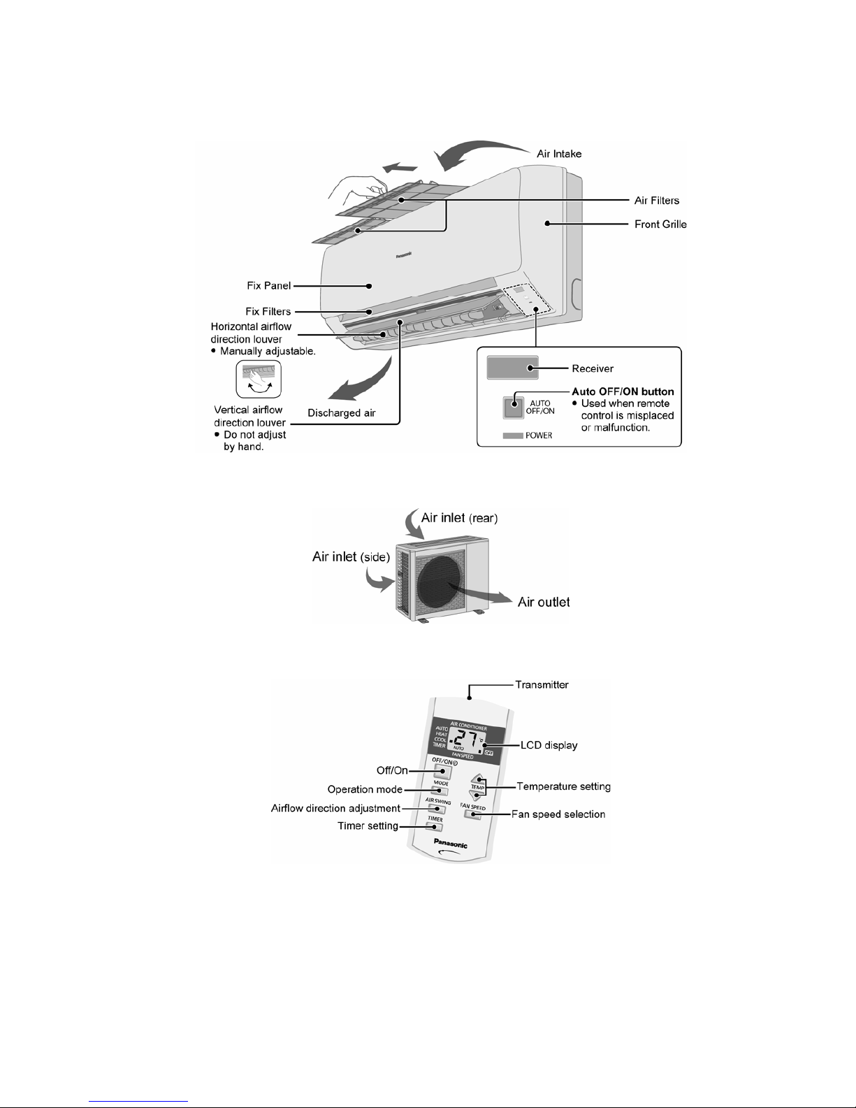
4. Location of Controls and Components
4.1 Indoor Unit
4.2 Outdoor Unit
4.3 Remote Control
10
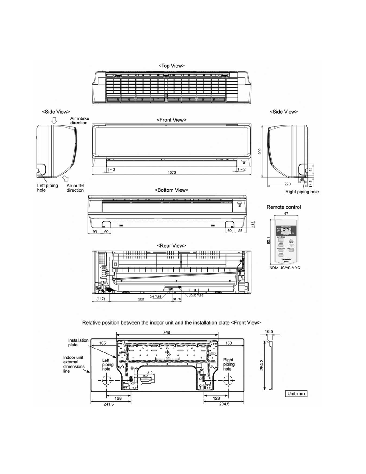
5. Dimensions
5.1 Indoor Unit & Remote Control
11
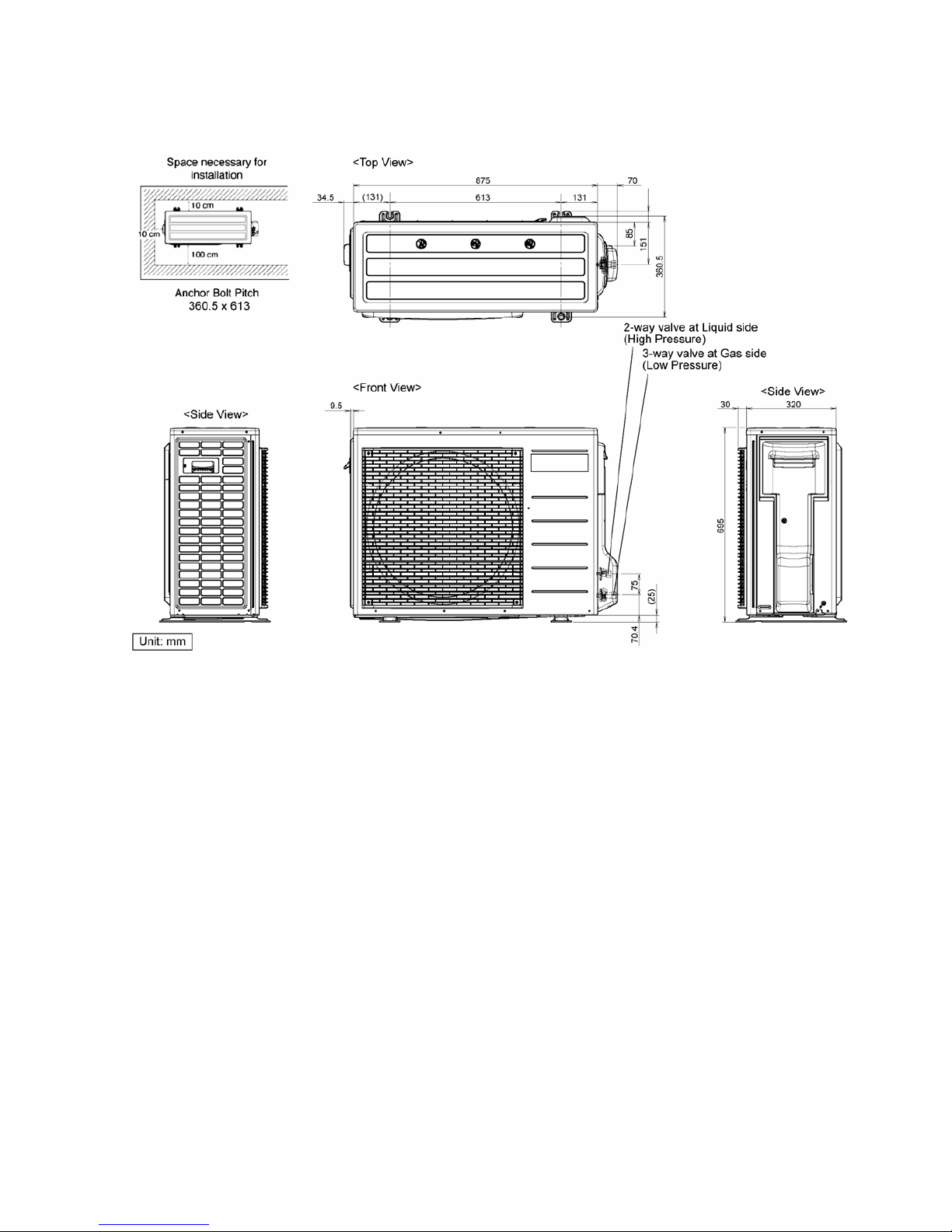
5.2 Outdoor Unit
5.2.1 CU-YE18NKV-6
12
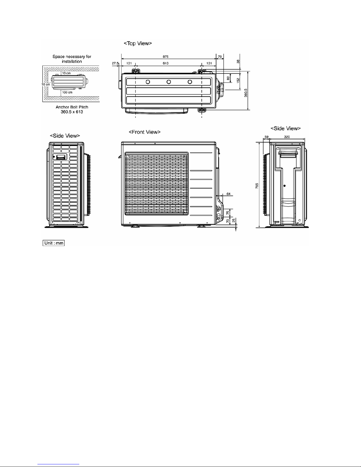
5.2.2 CU-YE24NKV-6
13
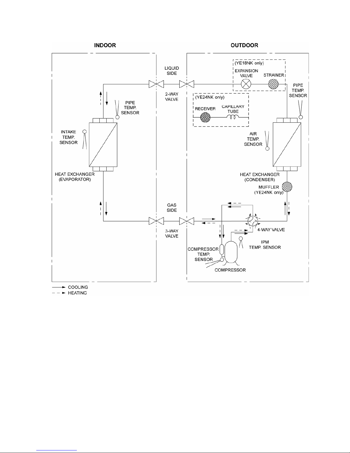
6. Refrigeration Cycle Diagram
14
7. Block Diagram
7.1 CS-YE18NKV-6 CU-YE18NKV-6
15
7.2 CS-YE24NKV-6 CU-YE24NKV-6
16
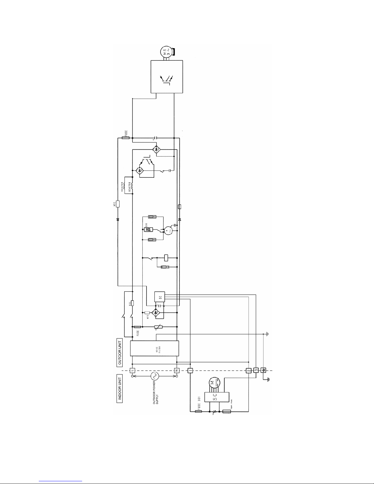
8. Wiring Connection Diagram
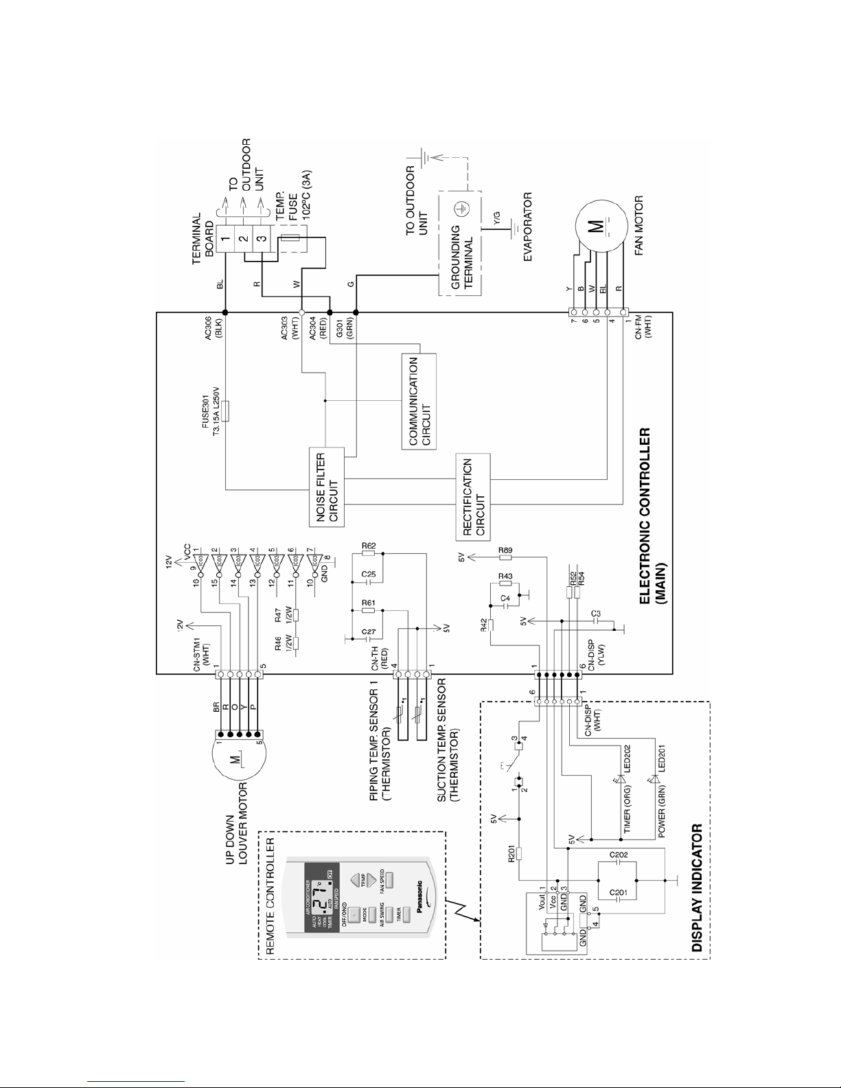
8.1 Indoor Unit
17
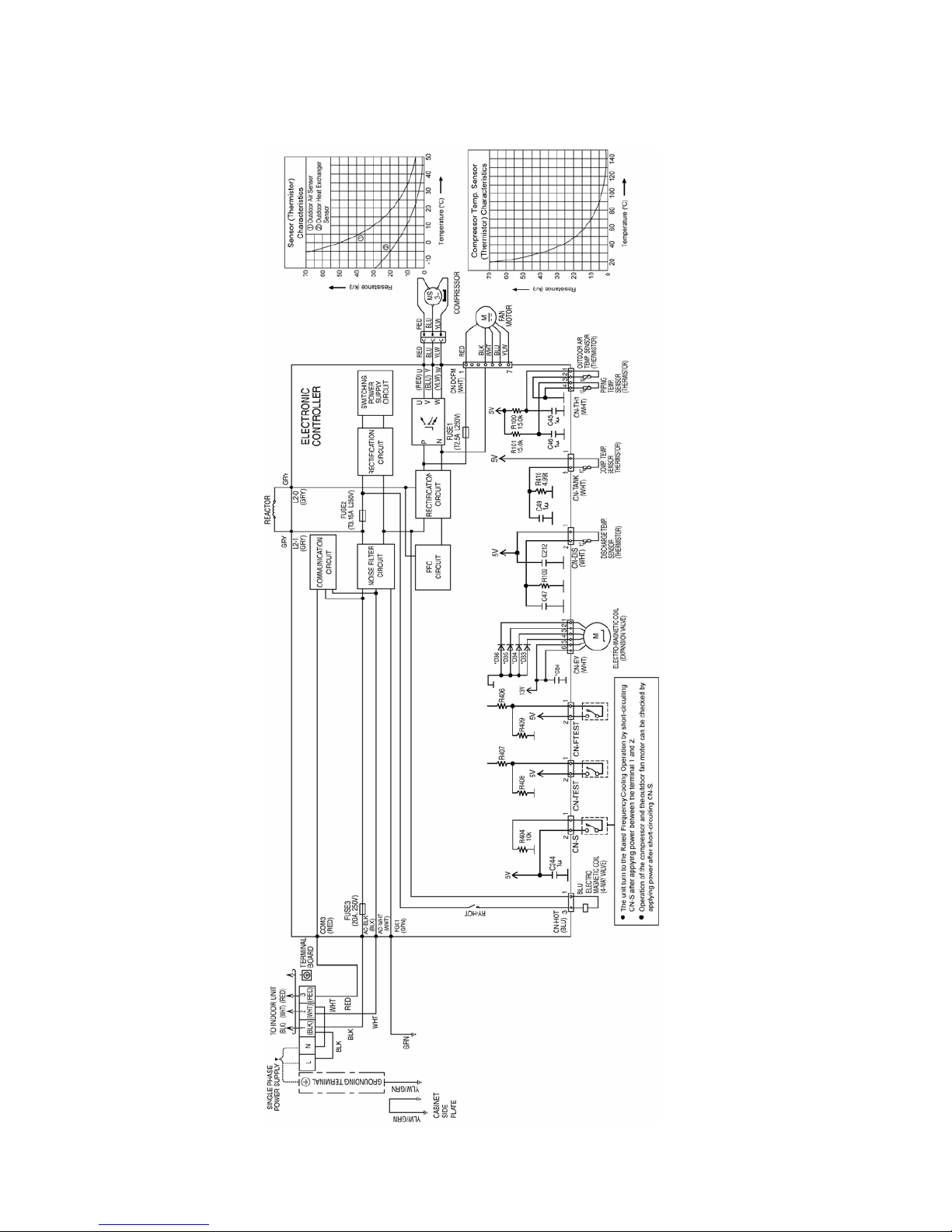
8.2 Outdoor Unit
8.2.1 CU-YE18NKV-6
18
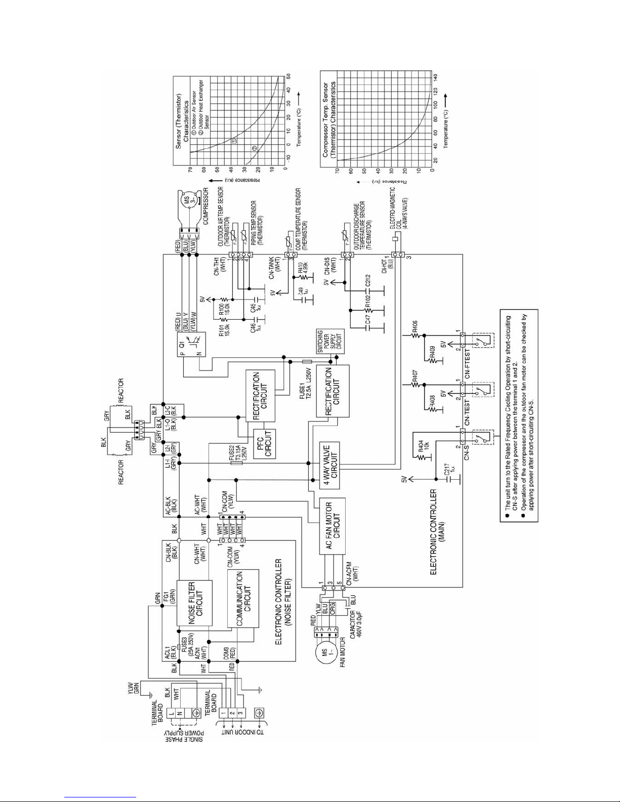
8.2.2 CU-YE24NKV-6
19
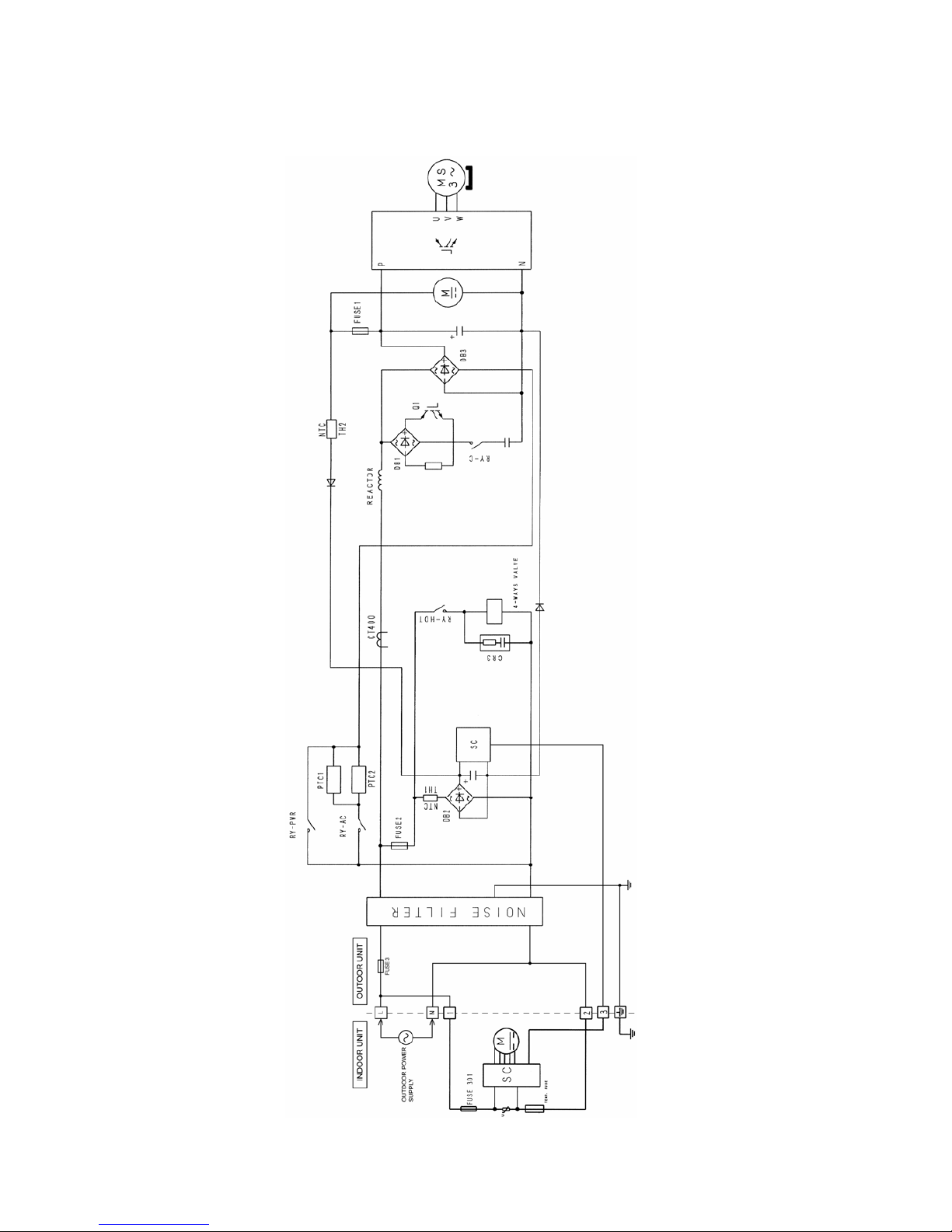
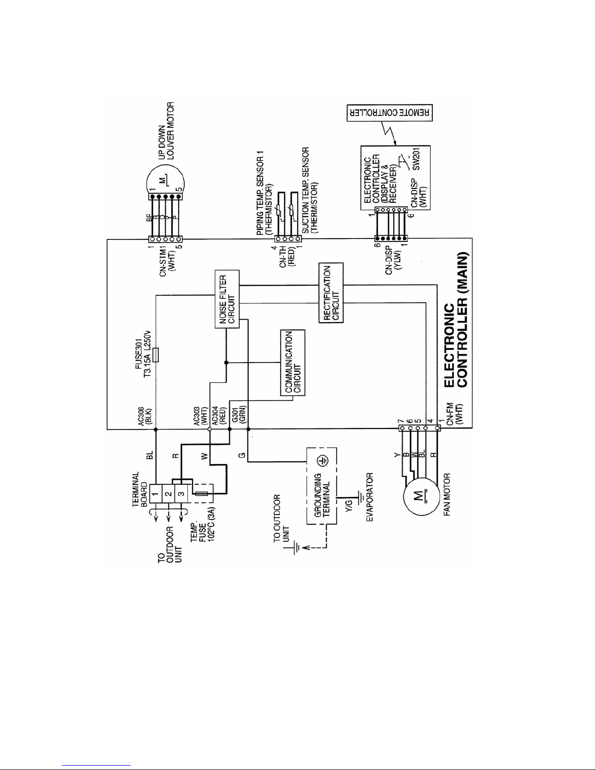
9. Electronic Circuit Diagram
9.1 Indoor Unit
20
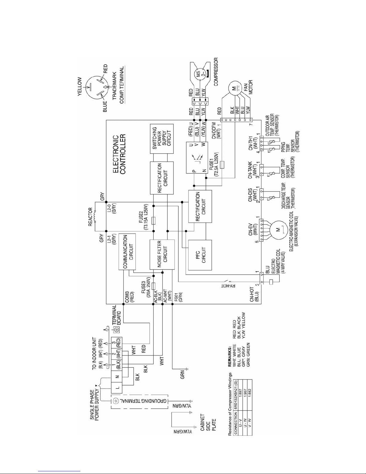
9.2 Outdoor Unit
9.2.1 CU-YE18NKV-6
21
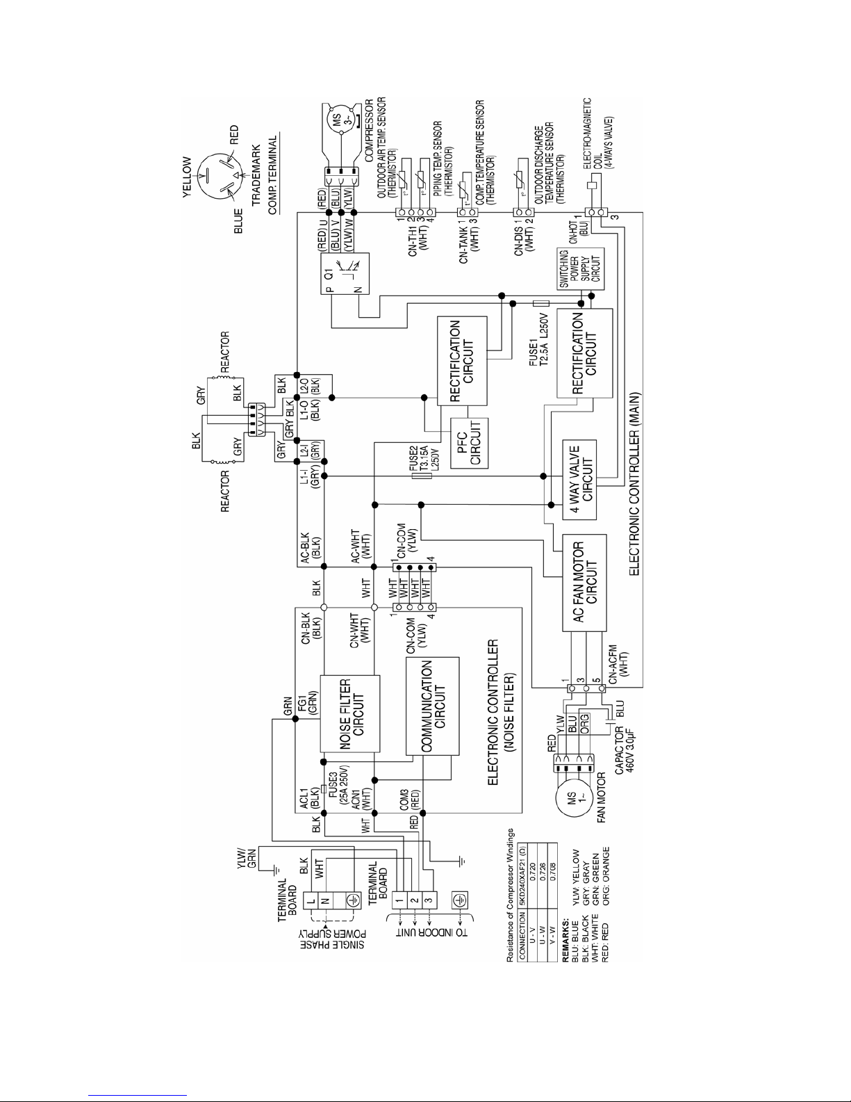
9.2.2 CU-YE24NKV-6
22
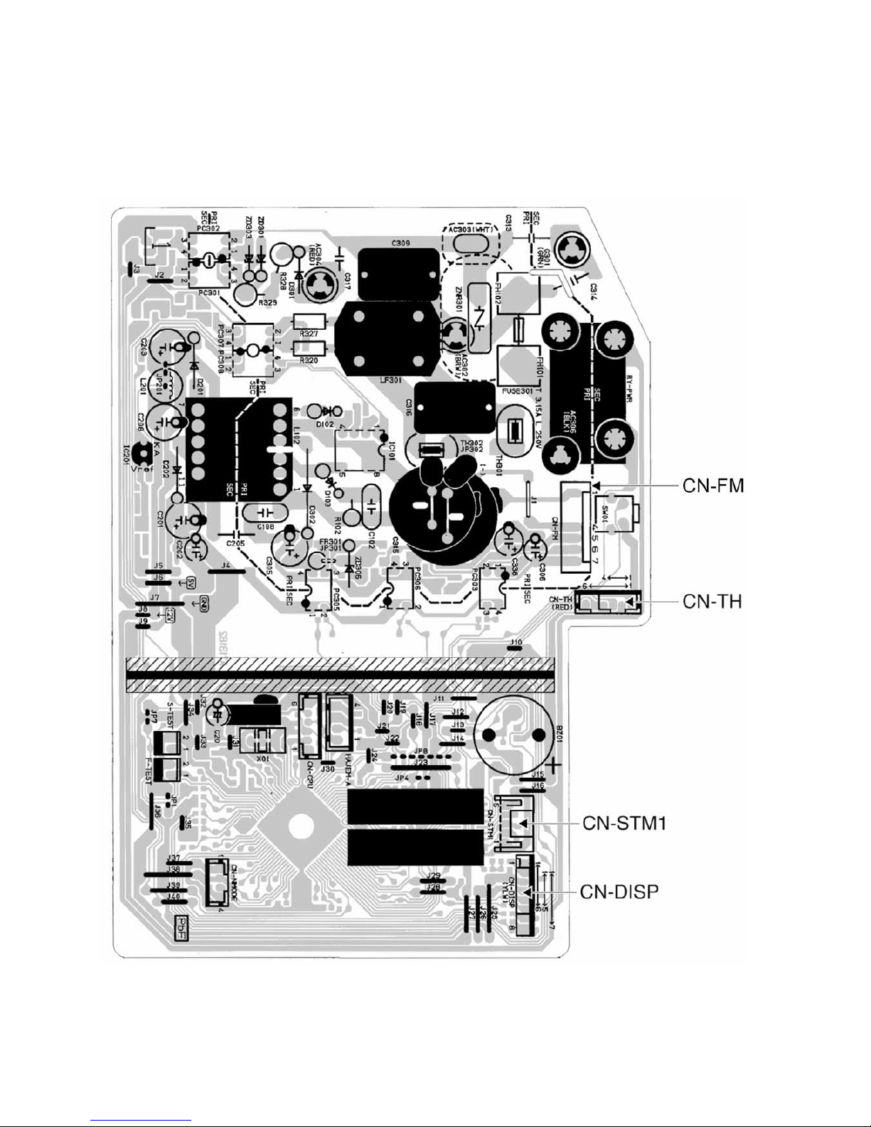
10. Printed Circuit Board
10.1 Indoor Unit
10.1.1 Main Printed Circuit Board
23
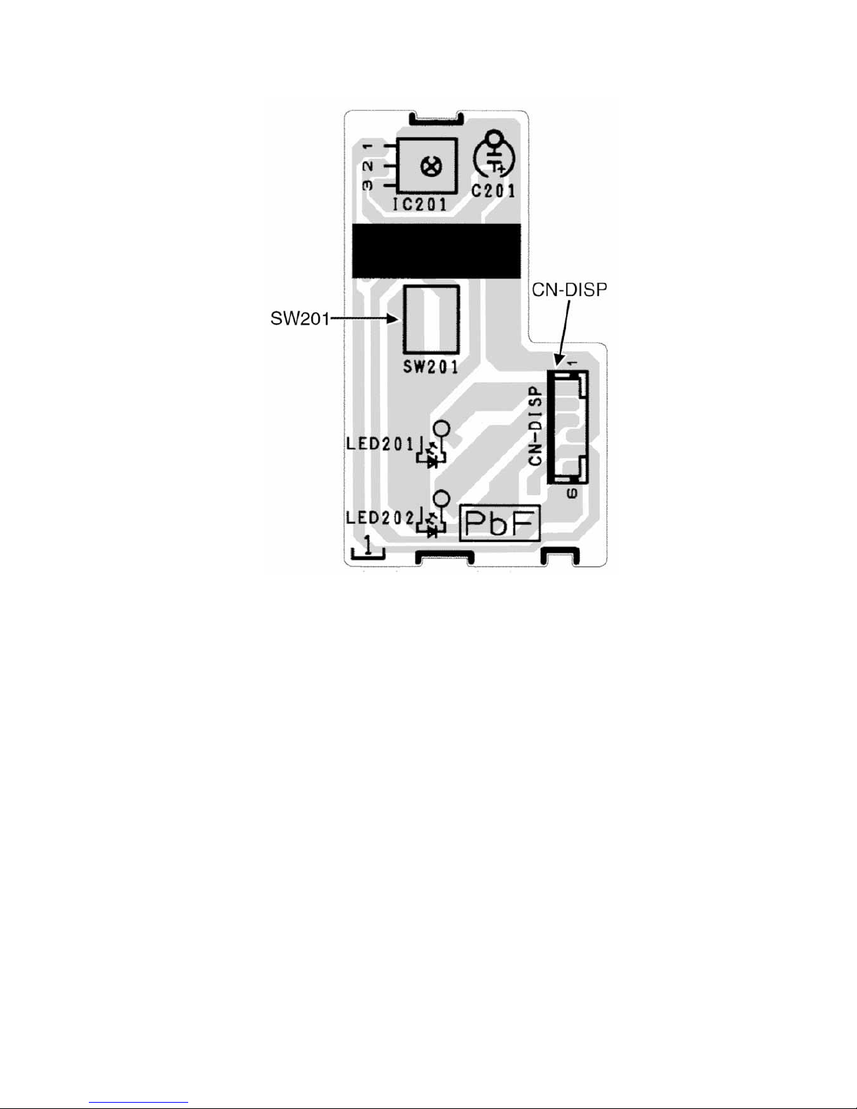
10.1.2 Indicator Printed Circuit Board
24
10.2 Outdoor Unit
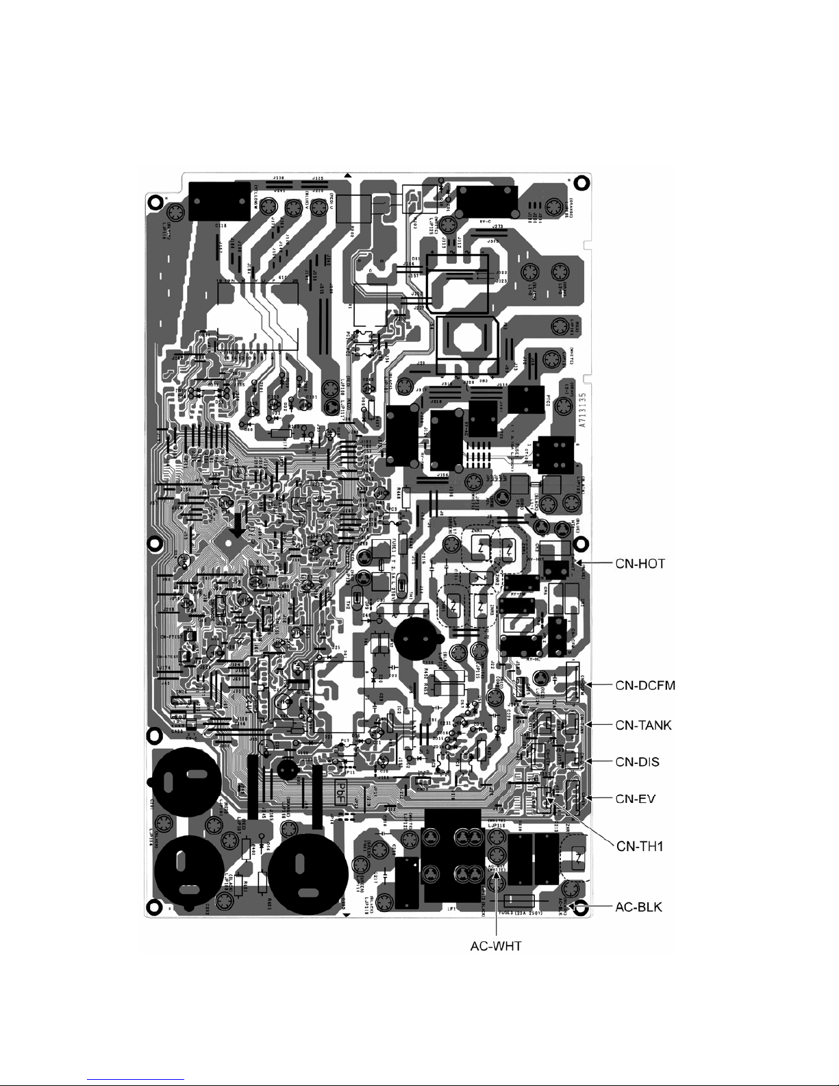
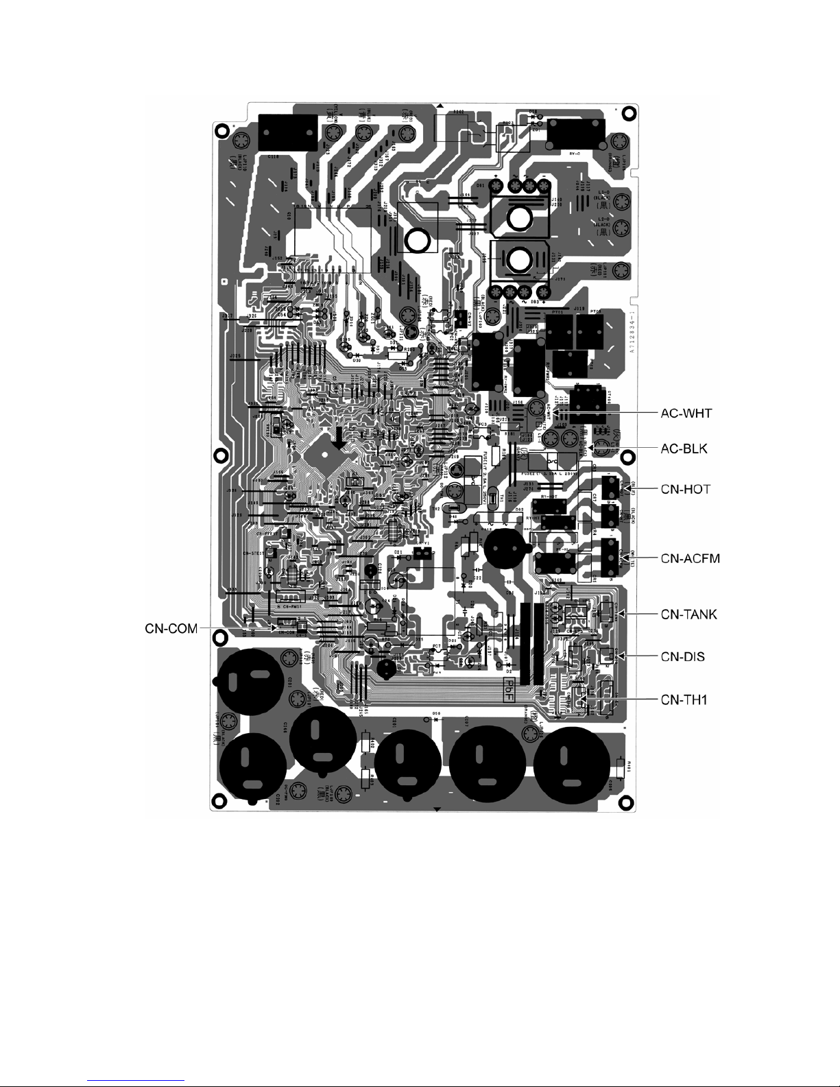
10.2.1 Main Printed Circuit Board
10.2.1.1 CU-YE18NKV-6
25
10.2.1.2 CU-YE24NKV-6
26
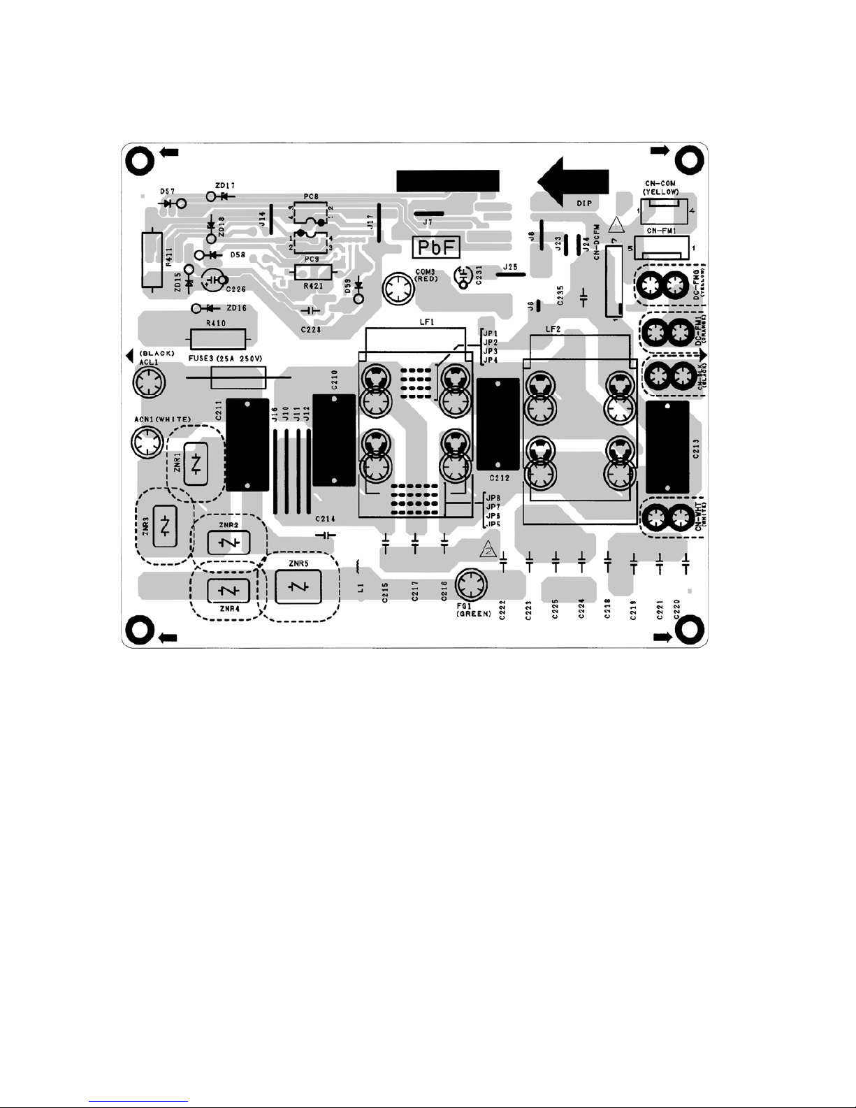
10.2.2 Noise Filter Printed Circuit Board
10.2.2.1 CU-YE24NKV-6
27
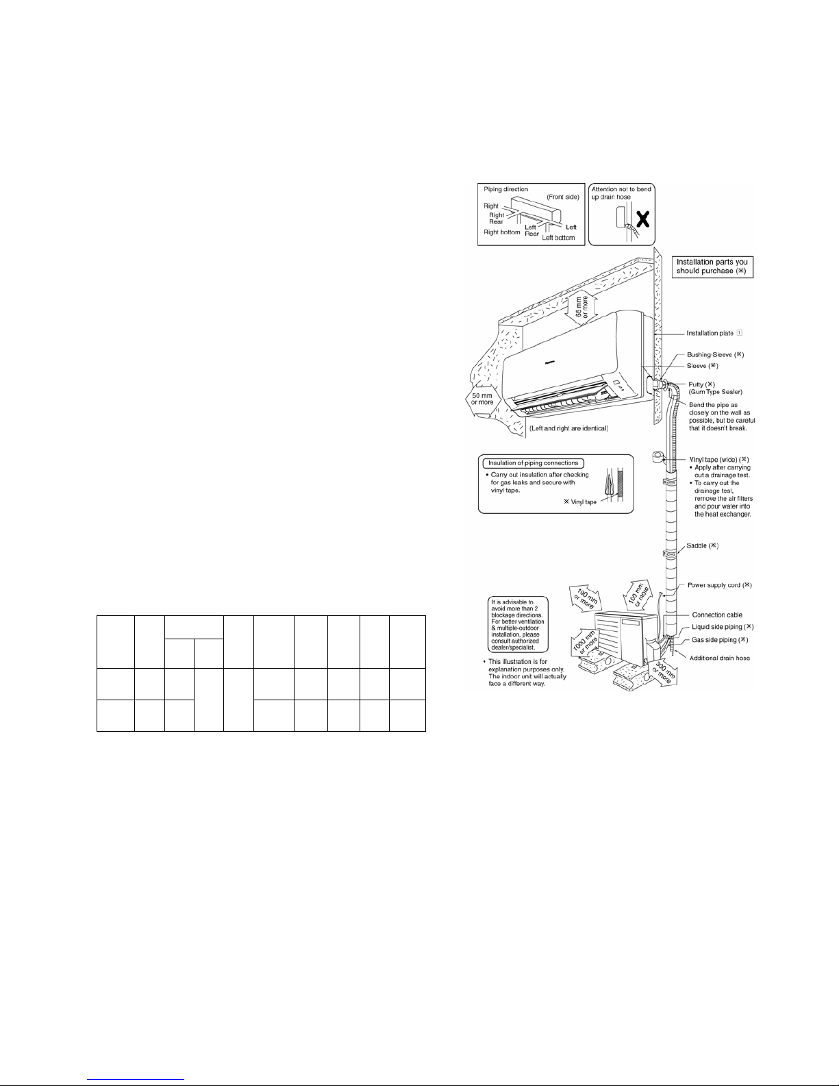
11. Installation Instruction
11.1 Select the Best Location
11.1.1 Indoor Unit
Do not install the unit in excessive oil fume area
such as kitchen, workshop and etc.
There should not be any heat source or steam
near the unit.
There should not be any obstacles blocking the air
circulation.
A place where air circulation in the room is good.
A place where drainage can be easily done.
A place where noise prevention is taken into
consideration.
Do not install the unit near the door way.
Ensure the spaces indicated by arrows from the
wall, ceiling, fence or other obstacles.
Recommended installation height for indoor unit
shall be at least 2.5 m.
11.1.2 Outdoor Unit
If an awning is built over the unit to prevent direct
sunlight or rain, be careful that heat radiation from
the condenser is not obstructed.
There should not be any animal or plant which
could be affected by hot air discharged.
Keep the spaces indicated by arrows from wall,
ceiling, fence or other obstacles.
Do not place any obstacles which may cause a
short circuit of the discharged air.
If piping length is over the [piping length for
additional gas], additional refrigerant should be
added as shown in the table.
Piping size
Model
Horse
Power
(HP)
Gas Liquid
Std.
Length
(m)
Max
Eleva-
tion (m)
Min.
Piping
Length
(m)
Max.
Piping
Length
(m)
Additional
Refri-
gerant
(g/m)
Piping
Length
for add.
gas (m)
YE18*** 2.0HP
12.7
mm
(1/2”)
10 3 20 20 7.5
YE24*** 2.0HP
15.88
mm
(5/8”)
6.35
mm
(1/4”)
5
10 3 30 30 10
Example: For YE18***
If the unit is installed at 10 m distance, the quantity of
additional refrigerant should be 50 g .... (10-7.5) m x
20 g/m = 50 g.
11.1.3 Indoor/Outdoor Unit Installation
Diagram
28
11.2 Indoor Unit
11.2.1 How to Fix Installation Plate
The mounting wall shall be strong and solid enough to prevent it from vibration.
Dimension
Model
1 2 3 4 5 6
YE18***, YE24*** 585 mm 82 mm 165 mm 158 mm 169 mm 219 mm
The center of installation plate should be at more than 1 at right and left of the wall.
The distance from installation plate edge to ceiling should more than 2.
From installation plate left edge to unit’s left side is 3.
From installation plate right edge to unit’s right is 4.
B : For left side piping, piping connection for liquid should be about 5 from this line.
: For left side piping, piping connection for gas should be about 6 from this line.
1 Mount the installation plate on the wall with 5 screws or more (at least 5 screws).
(If mounting the unit on the concrete wall, consider using anchor bolts.)
o Always mount the installation plate horizontally by aligning the marking-off line with the thread and using
a level gauge.
2 Drill the piping plate hole with ø70 mm hole-core drill.
o Line according to the left and right side of the installation plate. The meeting point of the extended line is
the center of the hole. Another method is by putting measuring tape at position as shown in the diagram
above. The hole center is obtained by measuring the distance namely 128 mm for left and right hole
respectively.
o Drill the piping hole at either the right or the left and the hole should be slightly slanting to the outdoor
side.
11.2.2 To Drill a Hole in the Wall and
Install a Sleeve of Piping
1 Insert the piping sleeve to the hole.
2 Fix the bushing to the sleeve.
3 Cut the sleeve until it extrudes about 15 mm
from the wall.
CAUTION
When the wall is hollow, please be sure to use the
sleeve for tube assembly to prevent dangers
caused by mice biting the connection cable.
4 Finish by sealing the sleeve with putty or
caulking compound at the final stage.
29
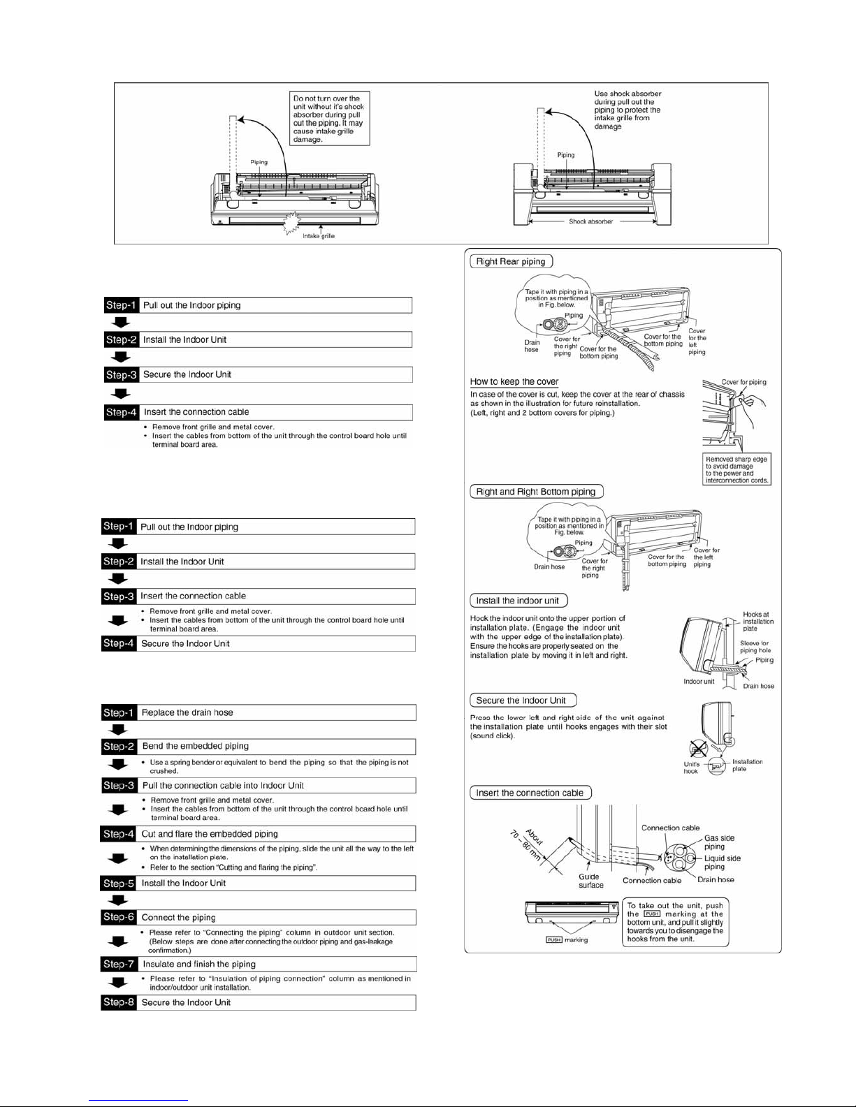
11.2.3 Indoor Unit Installation
11.2.3.1 For the Right Rear Piping
11.2.3.2 For the Right and Right Bottom
Piping
11.2.3.3 For the Embedded Piping
(This can be used for left rear piping and bottom
piping also.)
 Loading...