

Panasonic CS-W12CTP, CS-W18CTP, CU-W18CTP5, CU-W12CTP5, CS-W24CTP Service Manual
...
1 Functions 3
2 Product Specifications
6
3 Dimensions
12
4 Refrigeration Cycle Diagram
14
5 Block Diagram
16
6 Wiring Diagram
18
7 Operation Details
20
7.1. Cooling Mode Operation
20
7.2. Soft Dry Mode Operation
23
7.3. Heating Mode Operation
25
7.4. Automatic Mode Operation
31
© 2003 Matsushita Industrial Corp. Sdn. Bhd.
(11969-T). All rights reserved. Unauthorized copying
and distribution is a violation of law.
CS-W12CTP CU-W12CTP5
CS-W18CTP CU-W18CTP5
CS-W24CTP CU-W24CTP5
7.5. Sleep Mode Auto Operation 32
7.6. Random Auto Restart Control
33
7.7. Delay ON Timer Control
33
7.8. Remote Control Signal Receiving Sound
33
7.9. Indoor Fan Speed Control
34
7.10. Airflow direction control
34
7.11. Soft starter (Applicable only for Australia market)
35
8 Operating Instructions
36
9 Installation Instructions
44
9.1. Safety Precautions
44
Room Air Conditioner
CONTENTS
Page Page
Order No. MAC0305008C2

9.2. INDOOR UNIT 47
9.3. OUTDOOR UNIT
50
10 Installation and Servicing Air Conditione r Using R410A
56
10.1. OUTLINE
56
10.2. TOOL FOR INSTALLING / SERVICING REFRIGERANT
PIPING
57
10.3. REFRIGERANT PIPING WORK
61
10.4. INSTALLATION, TRANSFERRING, SERVICING
63
11 Servicing Information
67
12 Troubleshooting Guide
68
12.1. Refrigeration cycle system
68
13 Technical Data
70
14 Exploded View
74
15 Replacement Parts List
75
16 Exploded View
76
17 Replacement Parts List
77
18 Exploded View
78
19 Replacement Parts List
79
20 Electronic Circuit Diagram
80
20.1. REMOTE CONTROL
90
20.2. PRINT PATTERNINDOOR UNIT PRINTED CIRCUIT
BOARD
91
2
CS-W12CTP CU-W12CTP5 / CS-W18CTP CU-W18CTP5 / CS-W24CTP CU-W24CTP5
1 Functions
MODE SLEEP
F
A
N
S
P
E
E
D
RESET
TIME
R
A
U
T
O
M
A
N
U
A
L
A
U
T
AUT
O
H
E
A
HEA
T
C
O
OL
COOL
D
R
DR
Y
FAN
SPEE
D
SPEE
D
H
H
OFF
OFF
ON
ON
A
B
A
B
TEMP
OFF/ON
AIR SWING
S
E
L
E
C
T
S
E
T
/C
A
N
C
E
L
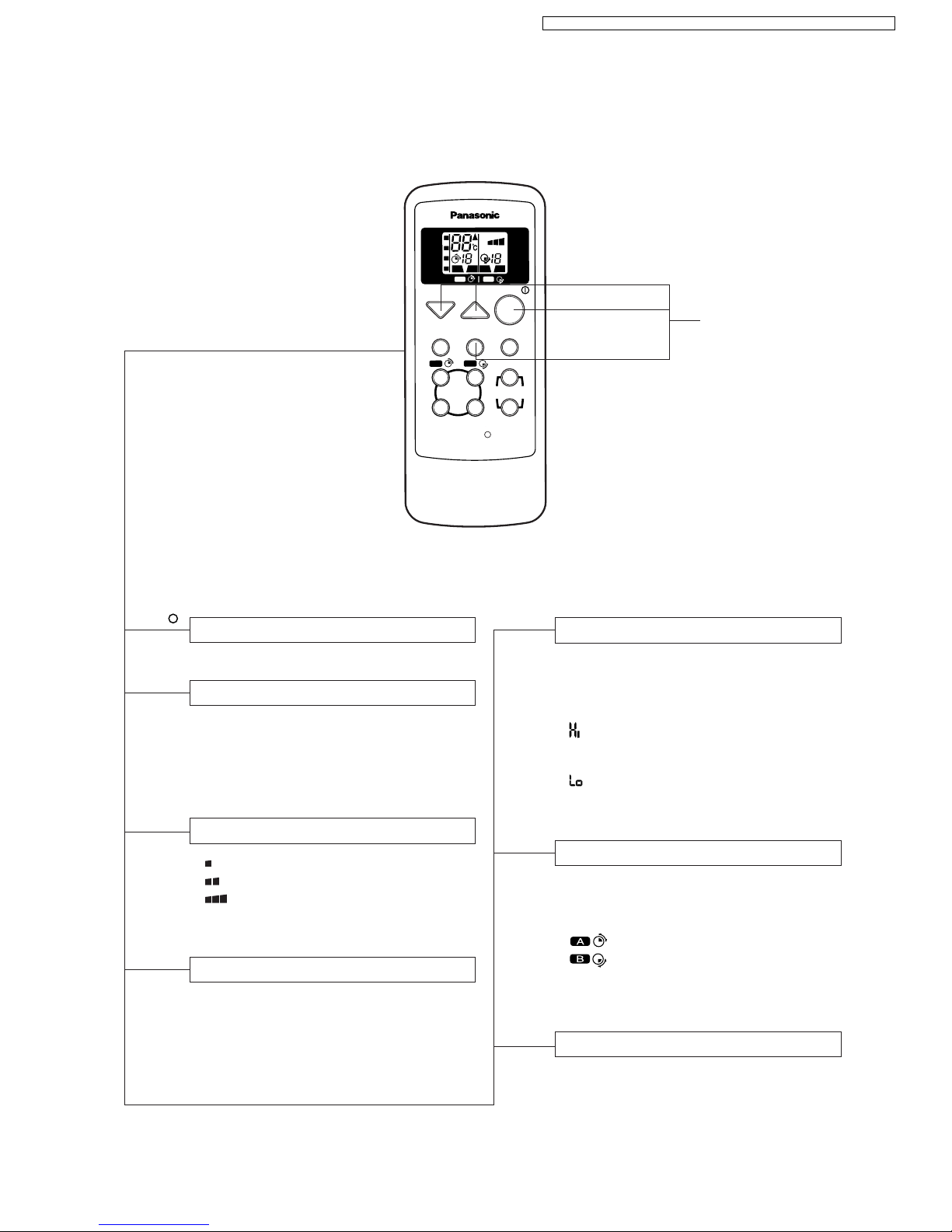
Remote Control
Operation OFF / ON Room Temperature Setting
TEMP.
Operation Mode Selection
•
AUTO
Automatic Operation Mode
•
HEAT
Heating Operation Mode
•
COOL
Cooling Operation Mode
•
DRY
Soft Dry Operation Mode
MODE
Sleep Mode Operation OFF / ON
Indoor Fan Speed Selection
FAN SPEED
• Low Fan Speed
•
Medium Fan Speed
•
High Fan Speed
•
AUTO
Automatic Fan Speed
Airflow Direction Control
TIMER
12-hour Timer Setting
AIR SWING
•
AUTO
Automatic Airflow Direction
Control
•
MANUAL
Airflow Direction Manual
Control
Heating, Cooling, Soft Dry Operation.
• Temperature Setting (16°C to 30°C)
Automatic Operation
•
Operation with 2°C higher than
standard temperature.
• Operation with standard temperature.
•
Operation with 2°C lower than
standard temperature.
•
SELECT To select delay OFF Timer,
ON Timer, OFF/ON Timer
and ON/OFF Timer
•
To set hours setting
•
To set hours setting
•
SET/CANCELTo start delay OFF and ON
timer, cancellation
OFF / ON
I
Self illuminating
button
SLEEP
3
CS-W12CTP CU-W12CTP5 / CS-W18CTP CU-W18CTP5 / CS-W24CTP CU-W24CTP5
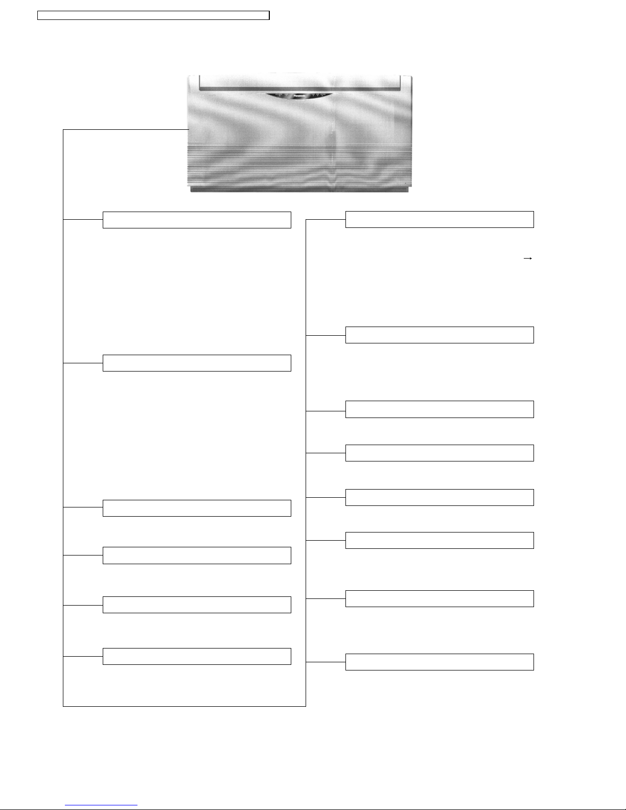
Indoor Unit
Sleep Mode Auto Control
• Indoor Fan operates refer to Indoor Fan
Speed.
• Operation stops after 8 hours.
Indoor Fan Speed Control
• High, Medium and Low.
• Automatic Fan Speed Mode
– Heating : Fan speed varies from Me
SSLo in accordance with
indoor heat exchanger.
– Cooling : Fan rotates at Hi, Me and
SLo speed.
– Soft Dry : Fan rotates at Lo- speed.
• Automatic air swing and manual adjusted
by remote control for vertical airflow.
• Manually adjusted by hand for horizontal
airflow.
Airflow Direction Control
Automatic Operation Button
• Press for < 5s to operate Automatic
operation mode.
(Used when the remote control cannot be used.)
• Press continuously for 5s or < 10s to
operate Test Run/Pump down. “Beep”
sound will be heard at the 5th second.
(Used when test running or servicing.)
• Press continuously for 10s and above to
omit or resume the remote control signal
receiving sound. “Beep, beep” sound will
be heard at the 10th second.
AUTO
OFF / ON
Operation Indication Lamps (LED)
•
POWER
(Green) ......... Lights up in operation,
blinks in Automatic
Operation Mode judging,
deice operation and
hotstart.
•
SLEEP
(Orange) .........Lights up in Sleep Mode
Operation.
•
TIMER
(Orange) ....... Lights up in Timer
Setting.
•
AIR SWING
(Orange) ... Lights up in Auto Air
Swing Mode Operation.
Time Delay Safety Control
•
Restarting is inhibited for appro. 3 minutes.
7 Minutes Time Save Control
• Cooling Operation only.
Anti-Dew Formation Control
• Anti-Dew Formation Control for indoor unit
discharge area.
Anti-Freezing Control
• Anti-Freezing control for indoor heat
exchanger. (Cooling and Soft Dry)
Random Auto Restart Control
• Operation is restarted randomly after
power failure at previous setting mode.
Operation Mode
• Heating, Cooling, Soft Dry and Automatic
Mode.
30 Minutes Time Save Control
• Heating Operation only.
Hot-Start Control
• At Heating Operation the indoor fan will
operate at SLo speed when indoor heat
exchanger temperature reaches 30°C.
Anti Cold Draft Control
• The indoor fan operates at SSLo when the
indoor heat exchanger temperature is low.
(During Heating mode thermal off)
4
CS-W12CTP CU-W 12CTP5 / CS-W18CTP CU-W 18CTP5 / CS-W 24CTP CU- W24CTP5
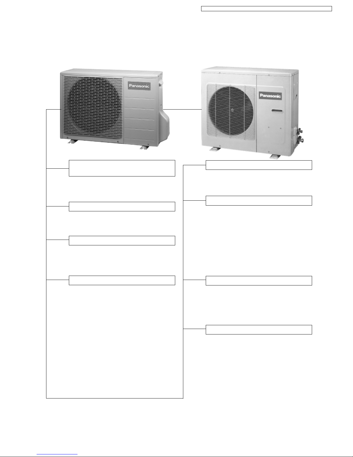
Outdoor Unit
CU-W12CTP5
• To protect compressor from reverse
rotation when there is a instantaneous
power failure.
60 Secs. Forced Operation Control
• Once the compressor is activated, it does
not stop within the first 60 secs.
However, it stops immediately with remote
control stop signal.
Overload Protector
• OLP to protect the compressor for W12CT
only.
Inner protector for W18CT & W24CT only.
Compressor Reverse Rotation
Protection Control
Outdoor Fan Operation Control
W18 / 24CT
• 4-pole induction motor (2 speed).
• For Cooling or Soft Dry operation
Hi-speed ............... When outdoor
temperature reaches to 31°C.
Lo-speed .............. When outdoor
temperature reaches to 29°C.
• For Heating operation
Hi-speed ............... When outdoor
temperature reaches to 13.5°C.
Lo-speed .............. When outdoor
temperature reaches to 15.5°C.
• For Over-heating Protection, the Fan is
switched ON or OFF depending on the
piping temperature and the outdoor
temperature.
W12CT
• 6-pole induction motor (1 speed).
CU-W18CTP5
CU-W24CTP5
4-Way Valve Control
• When the unit is switched to “OFF” during
Heating Operation, 4-way valve stays at
Heating position for 5 minutes.
Overload Protection Control
• Outdoor fan stops when indoor heat
exchanger temperature rises to 51°C and
above, and restarts when the indoor heat
exchanger temperature drops to 49°C and
below (W12CT).
• Compressor stop when indoor heat
exchanger temperature reaches 65°C
(W12CT), 68°C (W18CT & W24CT).
(Heating Operation Only)
Deice Control
• To prevent frosting at outdoor heat exchanger. (Only for Heating Operation)
Compressor Protection Control
• If the outdoor fan motor is not running after
compressor starts for 50 secs., compressor
will stop. (Cooling and Soft Dry Operation
only).
5
CS-W12CTP CU-W 12CTP5 / CS-W18CTP CU-W 18CTP5 / CS-W 24CTP CU- W24CTP5
2 Product Specifications
Unit CS-W12CTP CU-W12CTP5
Power Source Phase
V
Cycle
Single
230
50
Cooling Capacity kW
Btu/h
kcal/h
3.60
12,300
3,100
Heating Capacity kW
Btu/h
kcal/h
3.95
13,500
3,400
Moisture Removal l/h
Pint/h
2.1
4.4
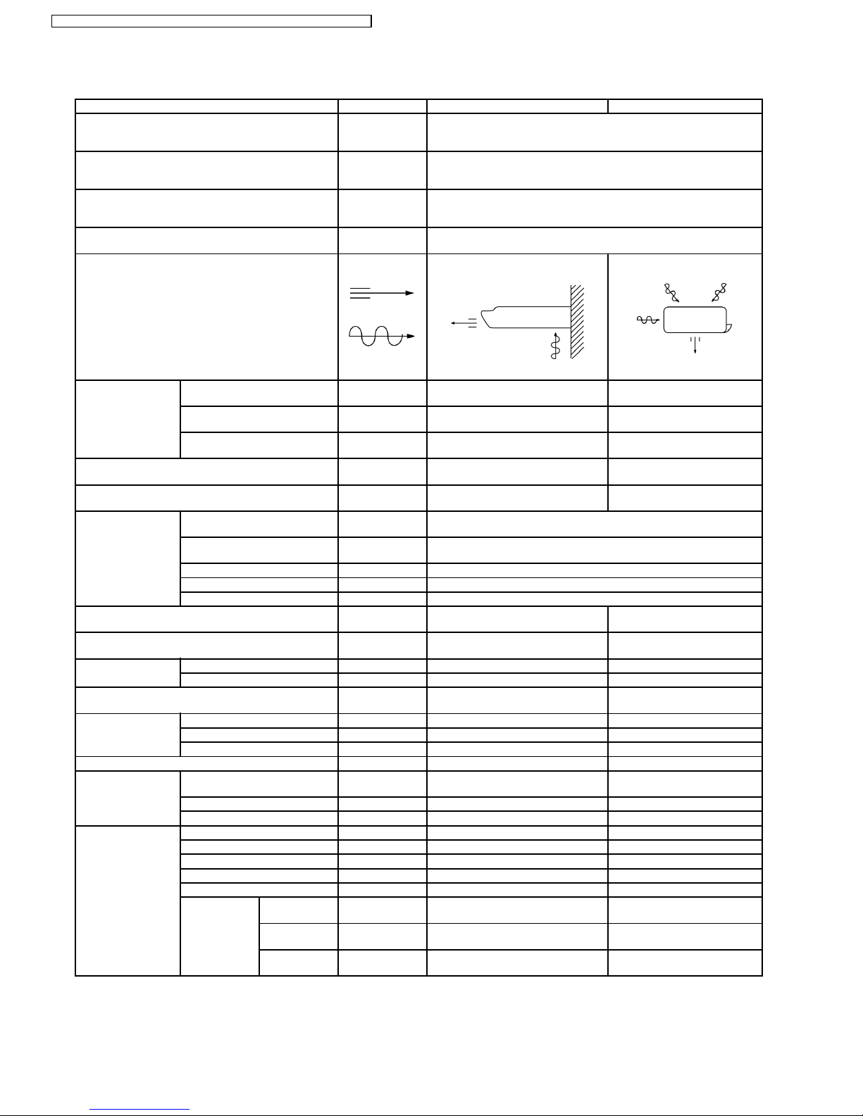
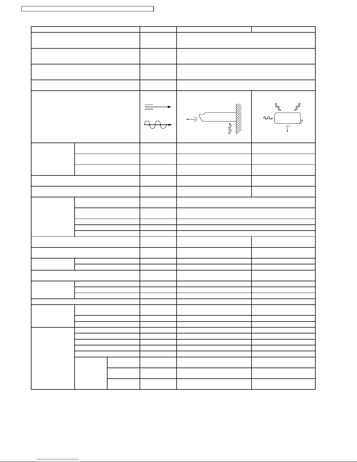
Airflow Method OUTLET
INTAKE
SIDE VIEW TOP VIEW
Air Volume Indoor Air (Lo) m3/min (cfm) Cooling: 7.5 (260)
Heating: 7.5 (260)
—
Indoor Air (Me) m3/min (cfm) Cooling: 8.9 (310)
Heating: 8.9 (310)
—
Indoor Air (Hi) m3/min (cfm) Cooling: 9.7 (340)
Heating: 9.7 (340)
33.0 (1,160)
Noise Level dB (A) Cooling: High 39; Low 33
Heating: High 39; Low 33
Cooling: High 49
Heating: High 49
Power Noise Level dB (A) Cooling: High 52
Heating: High 52
Cooling: High 64
Heating: High 65
Electrical Data Input Power W Cooling: 1,150
Heating: 1,180
Running Current A Cooling: 5.1
Heating: 5.3
EER W/W (Btu/hW) 3.13 (10.7)
COP W/W (Btu/hW) 3.35 (11.4)
Starting Current A 17.8
Piping Connection Port
(Flare piping)
inch
inch
G ; Half Union 1/2”
L ; Half Union 1/4”
G ; 3-way valve 1/2”
L ; 2-way valve 1/4”
Pipe Size
(Flare piping)
inch
inch
G (gas side) ; 1/2”
L (liquid side) ; 1/4”
G (gas side) ; 1/2”
L (liquid side) ; 1/4”
Drain
Hose
Inner diameter mm 20 —
Length m 0.6 —
Power Cord Length
Number of core-wire
m 1.8
3 (1.0 mm
2
)
—
—
Dimensions Height inch (mm) 21 - 9/32 (540) 21 - 9/32 (540)
Width inch (mm) 40 - 1/2 (1,028) 30 - 23/32 (780)
Depth inch (mm) 7 - 7/8 (200) 11 - 13/32 (289)
Net Weight lb (kg) 40 (18) 77 (35)
Compressor Type — Rotary (1 cylinder)
rolling piston type
Motor Type — Induction (2-poles)
Rated Output kW — 0.78
Air Circulation Type SIROCCO Propeller Fan
Material ABS STYLAC 181 PP
Motor Type Induction (4-poles) Induction (6-poles)
Input W 79.0 73
Rated Output W 29 33
Fan Speed Low rpm Cooling: 640
Heating: 640
—
Medium rpm Cooling: 760
Heating: 760
—
High rpm Cooling: 830
Heating: 830
845
6
CS-W12CTP CU-W 12CTP5 / CS-W18CTP CU-W 18CTP5 / CS-W 24CTP CU- W24CTP5
Unit CS-W12CTP CU-W12CTP5
Heat Exchanger Description Evaporator Condenser
Tube material Copper Copper
Fin material Aluminium Aluminium (Blue Coated)
Fin Type Louver Fin Corrugated Fin
Row / Stage (Plate fin configuration, forced draft)
2×12 2×24
FPI 20 17
Size (W × H × L) mm 857 × 252 × 25.4 705.8 × 504 × 36.38
735.1
Refrigerant Control Device — Capillary Tube
Refrigeration Oil (c.c) — RB68A or Freol Alpha 68M
(330)
Refrigerant (R410A) g (oz.) — 1,060 (37.4)
Thermostat Electronic Control —
Protection Device — Overload Protector
Capillary Tube Length mm — Cooling: 850, Heating: 590
Flow Rate l/min — Cooling: 4.5, Heating: 8.2
Inner Diameter mm — Cooling: 1.1, Heating: 1.3
Air Filter Material
Style
P.P.
Honeycomb
—
Capacity Control Capillary Tube
Compressor Capacitor µF, VAC — 35 µF, 370VAC
Fan Motor Capacitor µF, VAC 1.5 µF, 440VAC 2.0 µF, 450VAC
•
• •
•
Specifications are subject to change without notice for further improvement.
7
CS-W12CTP CU-W 12CTP5 / CS-W18CTP CU-W 18CTP5 / CS-W 24CTP CU- W24CTP5

Unit CS-W18CTP CU-W18CTP5
Power Source Phase
V
Cycle
Single
230
50
Cooling Capacity kW
Btu/h
kcal/h
5.20
17,700
4,470
Heating Capacity kW
Btu/h
kcal/h
5.80
19,800
4,990
Moisture Removal l/h
Pint/h
2.9
6.1
Airflow Method OUTLET
INTAKE
SIDE VIEW TOP VIEW
Air Volume Indoor Air (Lo) m3/min (cfm) Cooling: 9.7 (340)
Heating: 10.2 (360)
25.6 (900)
Indoor Air (Me) m3/min (cfm) Cooling: 10.7 (380)
Heating: 10.7 (380)
—
Indoor Air (Hi) m3/min (cfm) Cooling: 12.4 (440)
Heating: 12.4 (440)
40 (1,410)
Noise Level dB (A) Cooling: High 45; Low 39
Heating: High 45; Low 39
Cooling: High 55
Heating: High 56
Power Noise Level dB (A) Cooling: High 58
Heating: High 58
Cooling: High 68
Heating: High 69
Electrical Data Input Power W Cooling: 1,690
Heating: 1,740
Running Current A Cooling: 7.6
Heating: 7.9
EER W/W (Btu/hW) 3.07 (10.5)
COP W/W (Btu/hW) 3.33 (11.4)
Starting Current A 27
Piping Connection Port
(Flare piping)
inch
inch
G ; Half Union 1/2”
L ; Half Union 1/4”
G ; 3-way valve 1/2”
L ; 3-way valve 1/4”
Pipe Size
(Flare piping)
inch
inch
G (gas side) ; 1/2”
L (liquid side) ; 1/4”
G (gas side) ; 1/2”
L (liquid side) ; 1/4”
Drain
Hose
Inner diameter mm 20 —
Length m 0.6 —
Power Cord Length
Number of core-wire
m 1.8
3 (1.5 mm
2
)
—
—
Dimensions Height inch (mm) 21 - 9/32 (540) 26 - 31/32 (685)
Width inch (mm) 40 - 1/2 (1,028) 31 - 1/2 (800)
Depth inch (mm) 7 - 7/8 (200) 11 - 13/16 (300)
Net Weight lb (kg) 44 (20) 121 (55)
Compressor Type — Rotary (1 cylinder)
rolling piston type
Motor Type — Induction (2-poles)
Rated Output kW — 1.4
Air Circulation Type SIROCCO Propeller Fan
Material ABS STYLAC 181 AES + PC + GF15%
Motor Type Induction (4-poles) Induction (4-poles)
Input W 104.1 130
Rated Output W 51 67
Fan Speed Low rpm Cooling: 840
Heating: 880
640
Medium rpm Cooling: 920
Heating: 920
—
High rpm Cooling: 1,070
Heating: 1,040
1,020
8
CS-W12CTP CU-W 12CTP5 / CS-W18CTP CU-W 18CTP5 / CS-W 24CTP CU- W24CTP5
Unit CS-W18CTP CU-W18CTP5
Heat Exchanger Description Evaporator Condenser
Tube material Copper Copper
Fin material Aluminium Aluminium (Blue Coated)
Fin Type Louver Fin Corrugated Fin
Row / Stage (Plate fin configuration, forced draft)
2×12
+
1×10
2×26
FPI 20 16
Size (W × H × L) mm 857 × 252 × 25.4
+
857 × 210 × 12.7
769.2
732.9
×660.4×44
Refrigerant Control Device — Capillary Tube
Refrigeration Oil (c.c) — RB68A or Freol Alpha 68M
(670)
Refrigerant (R410A) kg (oz.) — 1.80 (63.5)
Thermostat Electronic Control Mecha. Control
Protection Device — Inner Protector
Capillary Tube Length mm — Cooling: 405, Heating: 1,048
Flow Rate l/min — Cooling: 7.8, Heating: 14.0
Inner Diameter mm — Cooling: 1.2, Heating: 1.8
Air Filter Material
Style
P.P.
Honeycomb
—
Capacity Control Capillary Tube
Compressor Capacitor µF, VAC — 50 µF, 370VAC
Fan Motor Capacitor µF, VAC 3.0 µF, 440VAC 3.0 µF, 450VAC
•
• •
•
Specifications are subject to change without notice for further improvement.
9
CS-W12CTP CU-W 12CTP5 / CS-W18CTP CU-W 18CTP5 / CS-W 24CTP CU- W24CTP5
Unit CS-W24CTP CU-W24CTP5
Power Source Phase
V
Cycle
Single
230
50
Cooling Capacity kW
Btu/h
kcal/h
6.90
23,500
5,930
Heating Capacity kW
Btu/h
kcal/h
7.65
26,100
6,580
Moisture Removal l/h
Pint/h
3.9
8.2
Airflow Method OUTLET
INTAKE
SIDE VIEW TOP VIEW
Air Volume Indoor Air (Lo) m3/min (cfm) Cooling: 10.5 (370)
Heating: 11.0 (390)
27.4 (970)
Indoor Air (Me) m3/min (cfm) Cooling: 11.8 (420)
Heating: 11.8 (420)
—
Indoor Air (Hi) m3/min (cfm) Cooling: 12.9 (460)
Heating: 12.9 (460)
47.2 (1,670)
Noise Level dB (A) Cooling: High 47; Low 42
Heating: High 47; Low 42
Cooling: High 60
Heating: High 61
Power Noise Level dB (A) Cooling: High 60
Heating: High 60
Cooling: High 74
Heating: High 75
Electrical Data Input Power W Cooling: 2,750
Heating: 2,890
Running Current A Cooling: 13.0
Heating: 13.7
EER W/W (Btu/hW) 2.51 (8.6)
COP W/W (Btu/hW) 2.65 (9.0)
Starting Current A 65
Piping Connection Port
(Flare piping)
inch
inch
G ; Half Union 5/8”
L ; Half Union 1/4”
G ; 3-way valve 5/8”
L ; 3-way valve 1/4”
Pipe Size
(Flare piping)
inch
inch
G (gas side) ; 5/8”
L (liquid side) ; 1/4”
G (gas side) ; 5/8”
L (liquid side) ; 1/4”
Drain
Hose
Inner diameter mm 20 —
Length m 0.6 —
Power Cord Length
Number of core-wire
m 1.8
3 (2.5 mm
2
)
—
—
Dimensions Height inch (mm) 21 - 9/32 (540) 26 - 31/32 (685)
Width inch (mm) 40 - 1/2 (1,028) 31 - 1/2 (800)
Depth inch (mm) 7 - 7/8 (200) 11 - 13/16 (300)
Net Weight lb (kg) 44 (20) 135 (61)
Compressor Type — Rotary (1 cylinder)
rolling piston type
Motor Type — Induction (2-poles)
Rated Output kW — 2.2
Air Circulation Type SIROCCO Propeller Fan
Material ABS STYLAC 181 AES + PC + GF15%
Motor Type Induction (4-poles) Induction (4-poles)
Input W 104.1 171.3
Rated Output W 51 108
Fan Speed Low rpm Cooling: 900
Heating: 940
680
Medium rpm Cooling: 1,010
Heating: 1,010
—
High rpm Cooling: 1,130
Heating: 1,100
1,170
10
CS-W12CTP CU-W 12CTP5 / CS-W18CTP CU-W 18CTP5 / CS-W 24CTP CU- W24CTP5

Unit CS-W24CTP CU-W24CTP5
Heat Exchanger Description Evaporator Condenser
Tube material Copper Copper
Fin material Aluminium Aluminium (Blue Coated)
Fin Type Louver Fin Corrugated Fin
Row / Stage (Plate fin configuration, forced draft)
2×12
+
1×10
2×26
FPI 20 16
Size (W × H × L) mm 857 × 252 × 25.4
+
857 × 210 × 12.7
769.2
732.9
×660.4×44
Refrigerant Control Device — Capillary Tube
Refrigeration Oil (c.c) — RB68A or Freol Alpha 68M
(1,130)
Refrigerant (R410A) kg (oz.) — 1.87 (66.0)
Thermostat Electronic Control Mecha. Control
Protection Device — Inner Protector
Capillary Tube Length mm — Cooling: 663, Heating: 550
Flow Rate l/min — Cooling: 13.0, Heating: 29.0
Inner Diameter mm — Cooling: 1.6, Heating: 2.4
Air Filter Material
Style
P.P.
Honeycomb
—
Capacity Control Capillary Tube
Compressor Capacitor µF, VAC — 45 µF, 370VAC
Fan Motor Capacitor µF, VAC 3.0 µF, 440VAC 3.0 µF, 450VAC
•
• •
•
Specifications are subject to change without notice for further improvement.
11
CS-W12CTP CU-W 12CTP5 / CS-W18CTP CU-W 18CTP5 / CS-W 24CTP CU- W24CTP5

3 Dimensions
12
CS-W12CTP CU-W 12CTP5 / CS-W18CTP CU-W 18CTP5 / CS-W 24CTP CU- W24CTP5
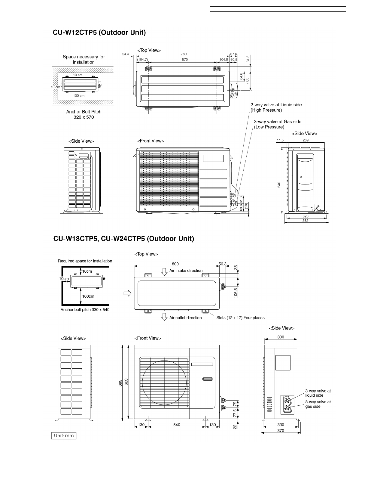
13
CS-W12CTP CU-W 12CTP5 / CS-W18CTP CU-W 18CTP5 / CS-W 24CTP CU- W24CTP5
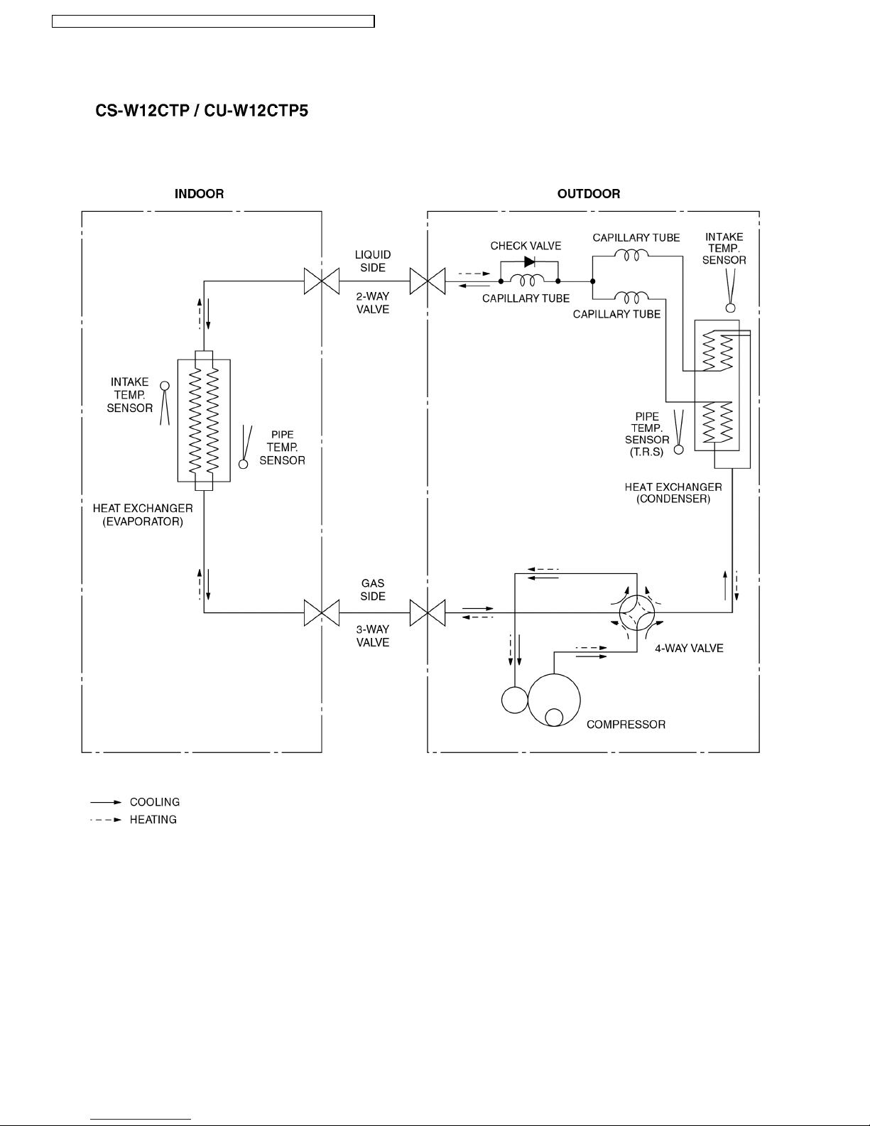
4 Refrigeration Cycle Diagram
14
CS-W12CTP CU-W 12CTP5 / CS-W18CTP CU-W 18CTP5 / CS-W 24CTP CU- W24CTP5
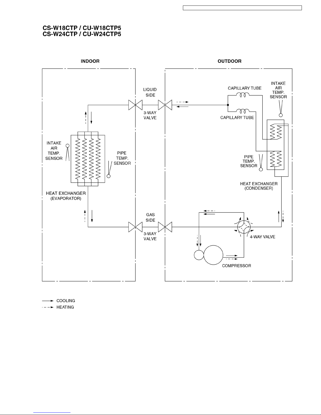
15
CS-W12CTP CU-W 12CTP5 / CS-W18CTP CU-W 18CTP5 / CS-W 24CTP CU- W24CTP5
5 Block Diagram
16
CS-W12CTP CU-W 12CTP5 / CS-W18CTP CU-W 18CTP5 / CS-W 24CTP CU- W24CTP5
17
CS-W12CTP CU-W 12CTP5 / CS-W18CTP CU-W 18CTP5 / CS-W 24CTP CU- W24CTP5
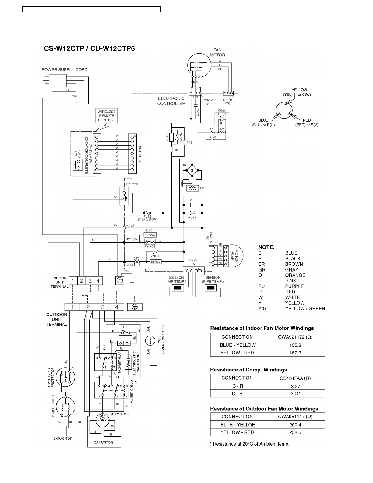
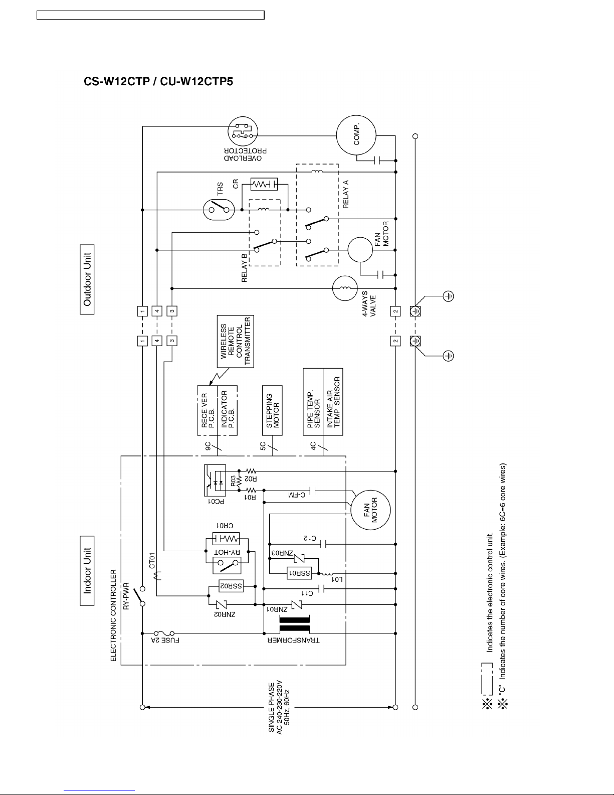
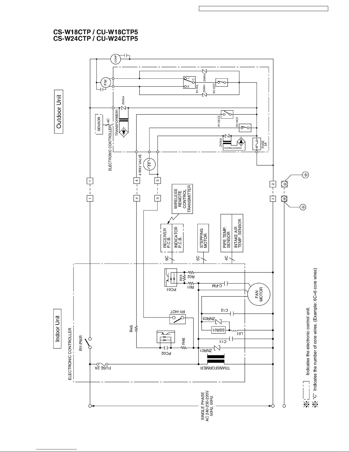
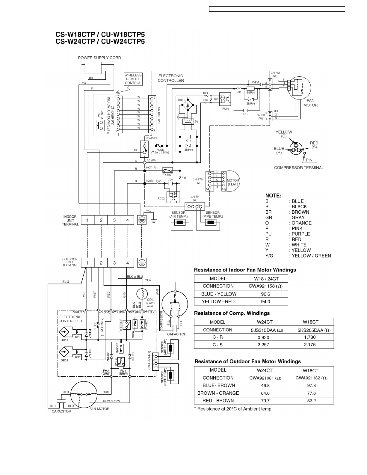
6 Wiring Diagram
18
CS-W12CTP CU-W 12CTP5 / CS-W18CTP CU-W 18CTP5 / CS-W 24CTP CU- W24CTP5
19
CS-W12CTP CU-W 12CTP5 / CS-W18CTP CU-W 18CTP5 / CS-W 24CTP CU- W24CTP5
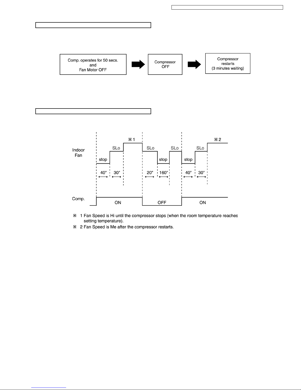
Cooling in operation according to Remote Control setting.
Time Delay Safety Control (3 minutes)
7 minutes Time Save Control
Anti-Freezing Control
•
• •
•
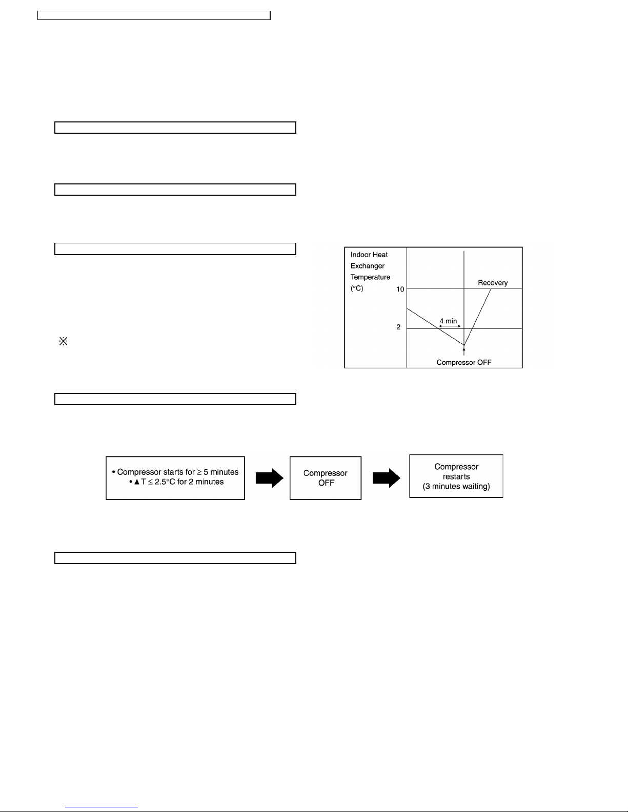
If the temperature of the indoor heat exchanger falls
continuously below 2°C for 4 minute s or more, the
compressor turns off to protect the indoor heat exchanger
from freezing. The fan speed setting remains the same.
•
• •
•
Compressor will restart again when the indoor heat
exchanger temperature rises to 10°C (Recovery).
3 minutes waiting of Time Delay Safety Control is valid for
Cooling Operation.
Compressor Reverse Rotation Protection Control
Anti-Dew Formation Control
7 Operation Details
7.1. Cooling Mode Operation
•
• •
•
When the compressor is stopped by Remote Control, it restarts after 3 minutes when it is turned ON by Remote Control.
•
• •
•
When the setting temperature is reached during cooling operation, the compressor stops and it will not start for 3 minutes.
•
• •
•
The compressor will start automatically if it has stopped for 7 minutes even if the room temperature is between the compressor
ON temperature and OFF temperature.
•
• •
•
If the compressor is operating continuously for 5 minutes or longer and the temperature difference between intake air and
indoor heat exchanger is 2.5°C or less for 2 minutes, compressor will stop and restart automatically.
(Time Delay Safety Control is valid)
!
T = Intake air temperature - Indoor heat exchan ger temperature
This is to protect reverse rotation of the compressor when there is a instantaneous power failure.
•
• •
•
Purpose is to prevent dew formation on indoor unit air discharge area.
•
• •
•
When the following conditions occur for 30 minutes continuously, anti-dew formation is controlled by indoor fan speed shift to
low (Changed to HLo):
−
− −
−
Indoor intake air temperature is more than 24°C and less than 30°C.
−
− −
−
Remote Control setting temperature is less than 25°C.
−
− −
−
Compressor is on.
−
− −
−
Cooling operation mode.
−
− −
−
Indoor Fan motor operate at Low fan speed.
•
• •
•
This control is cancelled immediately when above condition is changed.
20
CS-W12CTP CU-W 12CTP5 / CS-W18CTP CU-W 18CTP5 / CS-W 24CTP CU- W24CTP5
Compressor Protection Control
Automatic Fan Speed Mode
•
• •
•
After the compressor starts for 50 seconds but the outdoor fan motor is still OFF, the compressor will stop and restart
automatically. (Time Delay Safety Control is valid).
•
• •
•
If the above phenomenon is repeated for 3 times, the compressor will stop totally.
•
• •
•
The above phenomenon is reset when there is a change to heating mode or stopped by Remote Control Switch.
When Automatic Fan Speed is selected at Remote Control during cooling operation.
•
• •
•
Fan speed rotates in the range of Hi to Me.
21
CS-W12CTP CU-W 12CTP5 / CS-W18CTP CU-W 18CTP5 / CS-W 24CTP CU- W24CTP5
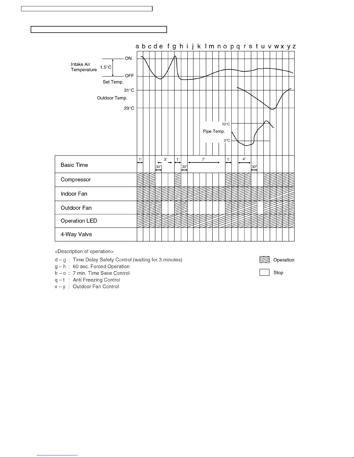
Cooling Operation Time Diagram
22
CS-W12CTP CU-W 12CTP5 / CS-W18CTP CU-W 18CTP5 / CS-W 24CTP CU- W24CTP5
Time Delay Safety Control
Anti-Freezing Control
Compressor Reverse Rotation Protection Control
Compressor Protection Control
Anti-Dew Formation Control
Automatic Fan Speed Mode
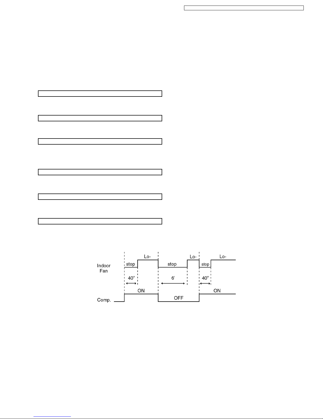
7.2. Soft Dry Mode Operation
•
• •
•
The unit starts cooling operation until the room temperature reaches the setting temperature set on the Remote Control, and
then Soft Dry operation will start.
•
• •
•
During Soft Dry operation, the Indoor Fan will operate at Lo- speed.
•
• •
•
The operation will be switched on and off for up to 10 minutes “ON” and 6 minutes “OFF”. Once Soft Dry operation is turned
off, it stops for 6 minutes.
•
• •
•
Once the compressor stops, it will not start for 3 minutes during Cooling operation.
•
• •
•
Same as Anti-Freezing Control for Cooling Mode operation. (For Soft Dry region, 6 minutes waiting is valid during compressor
stops.)
•
• •
•
Same as Compressor Reverse Rotation Protection Control for Cooling Mode Operation. (For Soft Dry region, 6 minutes waiting
is valid during compressor stops.)
•
• •
•
Same as Compressor Protection Control for Cooling Mode Operation.
•
• •
•
Same as Anti-Dew Formation Control for Cooling Mode operation.
When Automatic Fan Speed is selected at Remote Control during Soft Dry operation.
•
• •
•
Fan speed rotates at Lo- speed.
23
CS-W12CTP CU-W 12CTP5 / CS-W18CTP CU-W 18CTP5 / CS-W 24CTP CU- W24CTP5
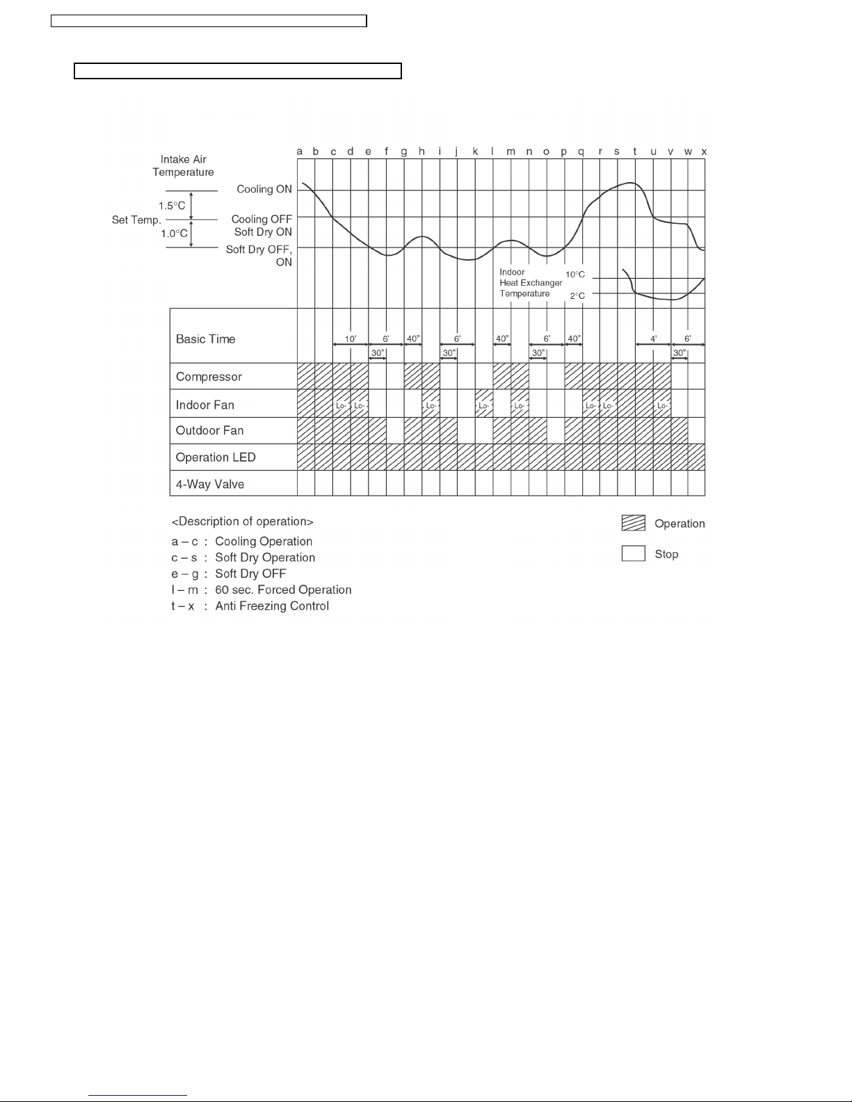
Soft Dry Operation Time Diagram
24
CS-W12CTP CU-W 12CTP5 / CS-W18CTP CU-W 18CTP5 / CS-W 24CTP CU- W24CTP5
Heating in operation according to Remote Control setting.
Time Delay Safety Control
30 minutes Time Save Control
Overload Protection Control
Compressor Reverse Rotation Protection Control
7.3. Heating Mode Operation
•
• •
•
When the compressor is stopped by Remote Control, it restarts after 3 minutes when the Remote Control is turned ON.
•
• •
•
When the setting temperature is reached during heating operation, the compressor stops and it will not start for 4 minutes.
•
• •
•
The compressor will start automatically if it has stopped for 30 minutes even if the room temperature is between the compressor
ON temperature and OFF temperature.
(a) Outdoor Fan Control
•
• •
•
W12CT
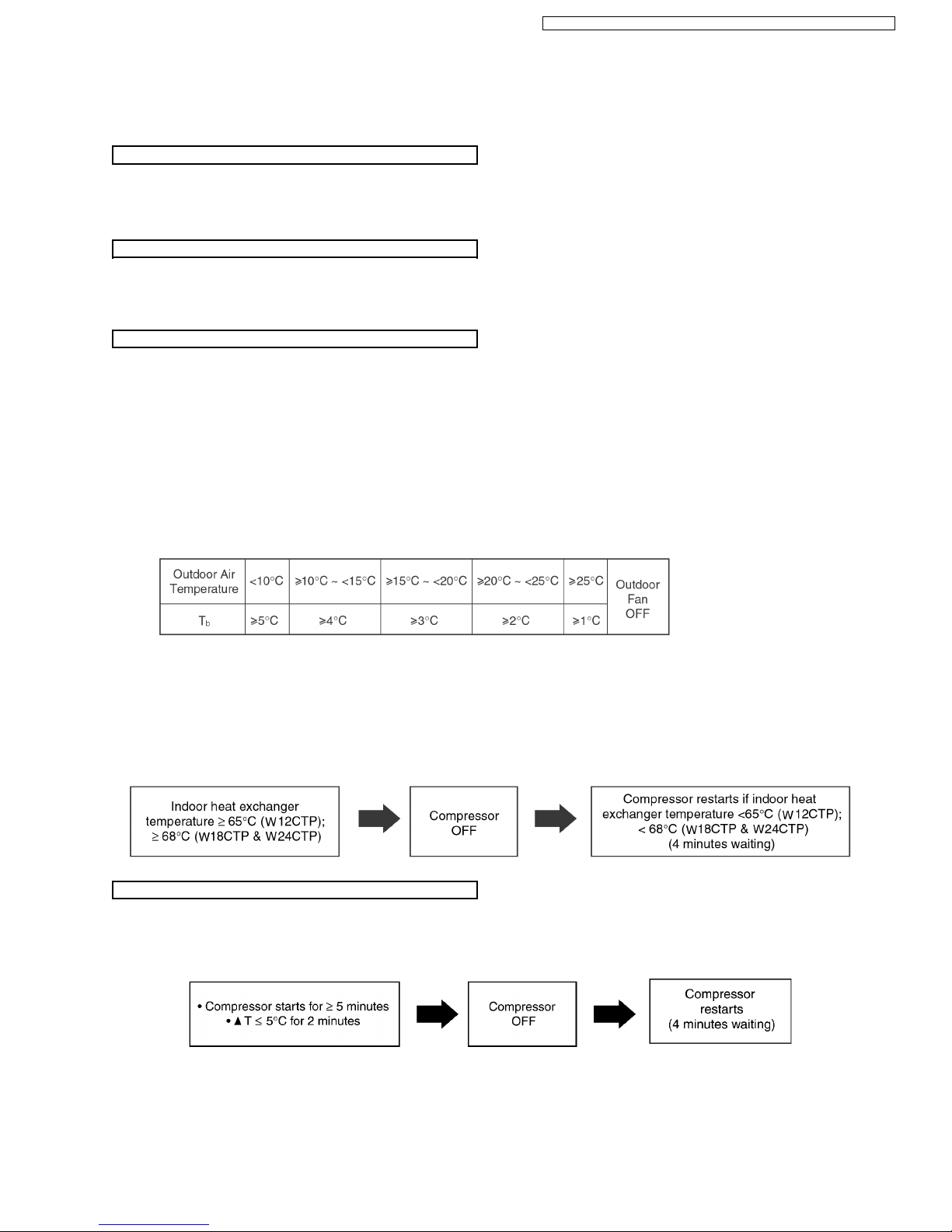
If the temperature of the indoor heat exchanger rises to 51°C, Outdoor Fan stops.
The Outdoor Fan restarts when the indoor heat exchan ger temperature falls to 49°C.
•
• •
•
W18CT, W24CT
If the temperature of the Outdoor Heat Exchanger less than -3°C, Outdoor Fan is ON. The Outdoor Fan stop, when Outdoor
Heat Exchanger temperature is T
b
or more according to Outdoor Air Temperature region as table below:
The Outdoor Fan restarts when the indoor heat exchan ger temperature falls to 49°C.
During starting of Heating mode and after deice, Outdoor Fan ON for 90 sec.
(b) Compressor high pressure protection
•
• •
•
If the indoor heat exchan ger becomes 65°C (W12CTP); 68°C (W18CTP & W24CTP) or more, the compressor will stop and
restart automatically.
(Time Delay Safety Control - 4 minutes waiting).
•
• •
•
If the compressor is operating continuously for 5 minutes or longer and temperature difference between intake air and indoor
heat exchanger is 5°C or less for 2 minutes, compressor will stop and restart automatically.
(Time Delay Safety Control is valid).
!
T = Indoor heat exchanger temperature - intake air temperature.
This is to protect reverse rotation of the compressor when there is a instantaneous power failure.
25
CS-W12CTP CU-W 12CTP5 / CS-W18CTP CU-W 18CTP5 / CS-W 24CTP CU- W24CTP5
4-way Valve Control
Outdoor Fan Motor Control
Indoor Fan Motor Control
Hot Start Control
Anti Cold Draft Control
•
• •
•
4-way valve always ON during Heating operation. (Except Deicing operation)
•
• •
•
When the unit is switched to “OFF” during Heating operation, 4-way valve stay at Heating position for 5 minutes.
•
• •
•
When compressor stops (reaches room temperature), outdoor fan will operate for 30 seconds.
(30 second s Forced Operation).
•
• •
•
When compressor stops (reaches room temperature), indoor fan will stop for 1 minutes, operate for 3 minutes, if still not yet
reaches the room temperature, indoor fan Lo- for 40 sec. after that operate at SLo speed.
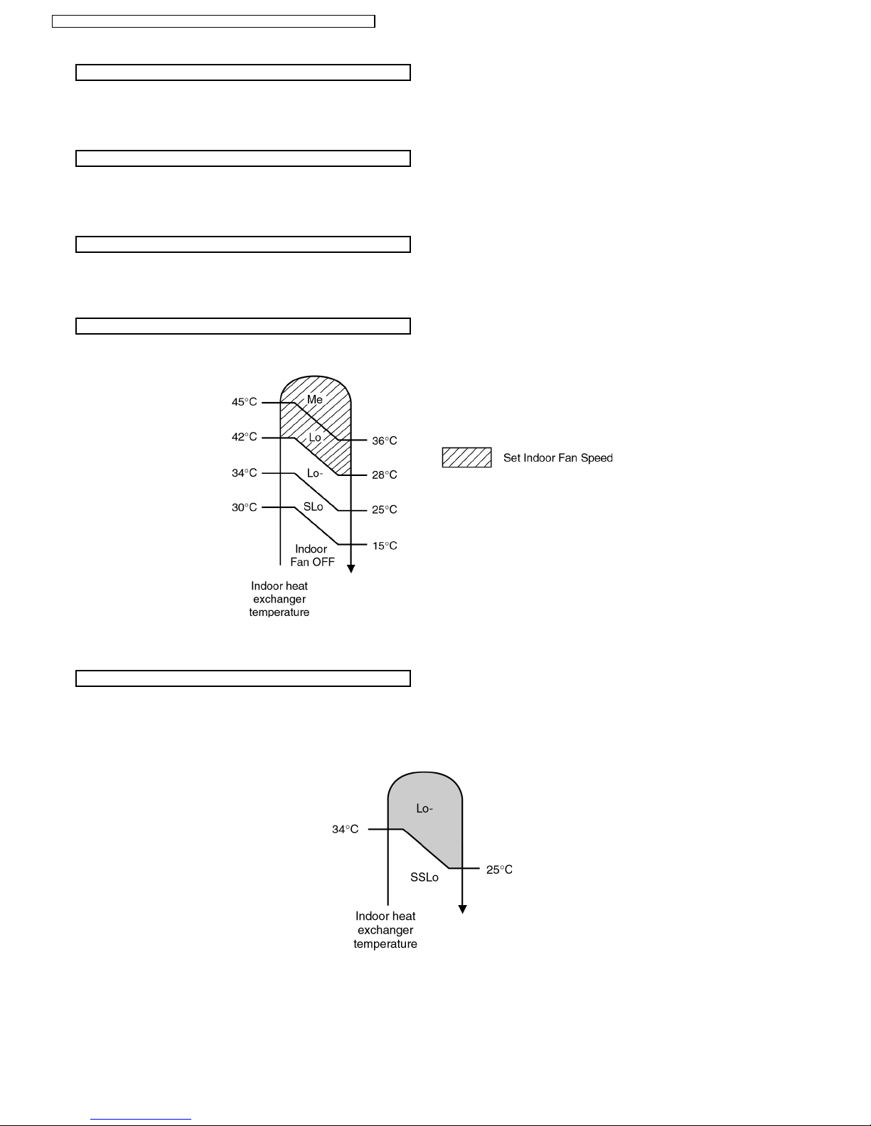
When Heating operation starts, Indoor Fan will not start until the indoor heat exchanger reaches 30°C as diagram shown.
Hot Start is completed when indoor heat exchanger rises to 42°C or over 4 minutes.
•
• •
•
This operation is to prevent the Cold Draft during Heating mode operation.
•
• •
•
The operation will start when compressor OFF (Thermo OFF) during Heating operation.
•
• •
•
For the first 30 sec. from compressor OFF (Thermo OFF), Indoor fan speed will operate accordingly to the Indoor heat
exchanger temperature as shown below:
•
• •
•
After 30 sec. from compressor OFF (thermo OFF), Indoor fan will run at SSLo speed only.
•
• •
•
Anti Cold Draft Control will stop when:
−
− −
−
Intake temperature < set temperature. (Time Delay Safety Control 4 minutes waiting is valid)
−
− −
−
After 30 minutes time saved control.
26
CS-W12CTP CU-W 12CTP5 / CS-W18CTP CU-W 18CTP5 / CS-W 24CTP CU- W24CTP5
Automatic Fan Speed Mode
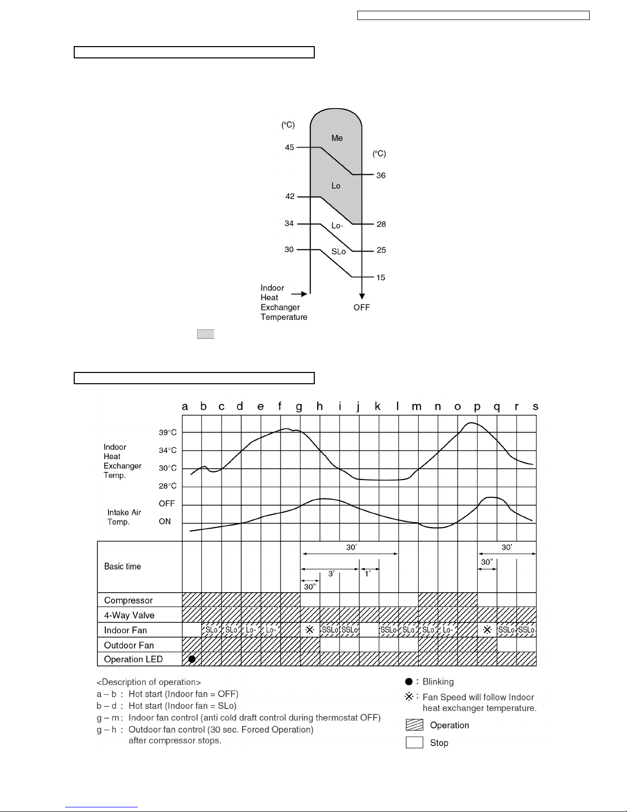
Heating Operating Time Diagram
When Automatic Fan Speed is selected at Remote Control during heating operation.
•
• •
•
Fan speed rotates in the range of Me→SLo according to the heat exchanger temperature.
•
• •
•
If use Manual Fan Speed,
at above diagram will operate with setting Fan Speed.
27
CS-W12CTP CU-W 12CTP5 / CS-W18CTP CU-W 18CTP5 / CS-W 24CTP CU- W24CTP5
Deicing Control
1) W12C T
Deice starts to prevent frosting at outdoo r heat exchanger.
•
• •
•
Normal Deicing
Deice operations detection commences after 30 minutes of Heating operation starts or 60 minutes after previous deice
operation. If the TRS (Thermal Reed Switch) senses the outdoor piping temperature drops to -3°C (TRS CLOSE) or less for
50 sec. continu ously during compressor is in operation, deice will start.
(There is no detection during Outdoor Fan stops.)
•
• •
•
Overload Deicing
During heating operation, if the outdoor Fan OFF duration (due to overload control) is accumulated up to 60 minutes and
after compressor starts for 1 minutes, deicing starts.
•
• •
•
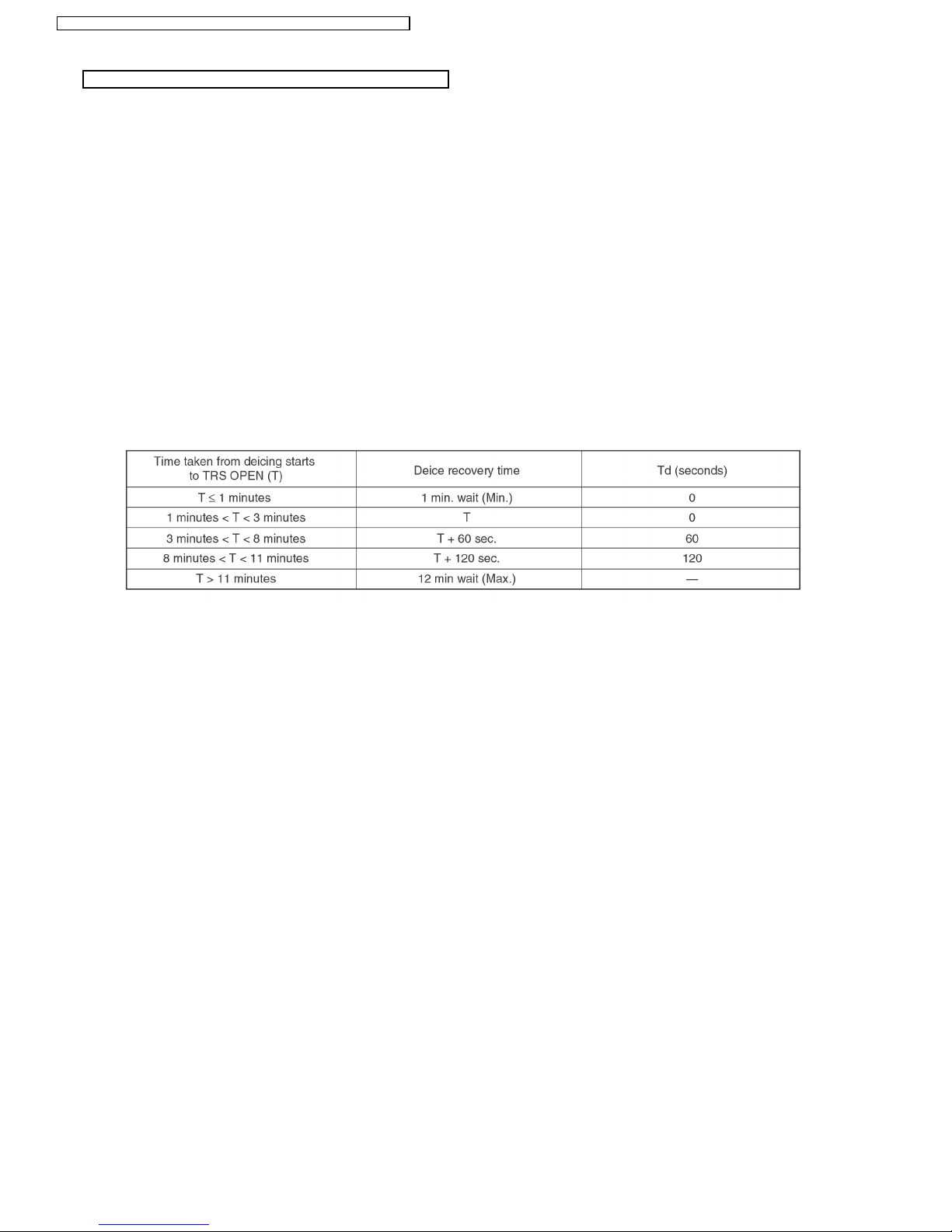
Deicing ends when
1. 12 minutes after deicing operation starts;
2. TRS senses the outdoo r piping temperature rises to 4°C (TRS OPEN).
3. Deicing will not end immediately as time delay (Td) is valid as shown below.
•
• •
•
Once deicing operation starts, it will not end for 60 seconds.
•
• •
•
After deicing operation, compressor stops for 30 seconds and 4-way valve stays at cooling position for 10 seconds.
28
CS-W12CTP CU-W 12CTP5 / CS-W18CTP CU-W 18CTP5 / CS-W 24CTP CU- W24CTP5
 Loading...