

Panasonic CS-W18CKE, CU-W18CKE, CS-W24CKE, CU-W24CKE Service Manual
1 Features 2
2 Functions
3
3 Product Specifications
6
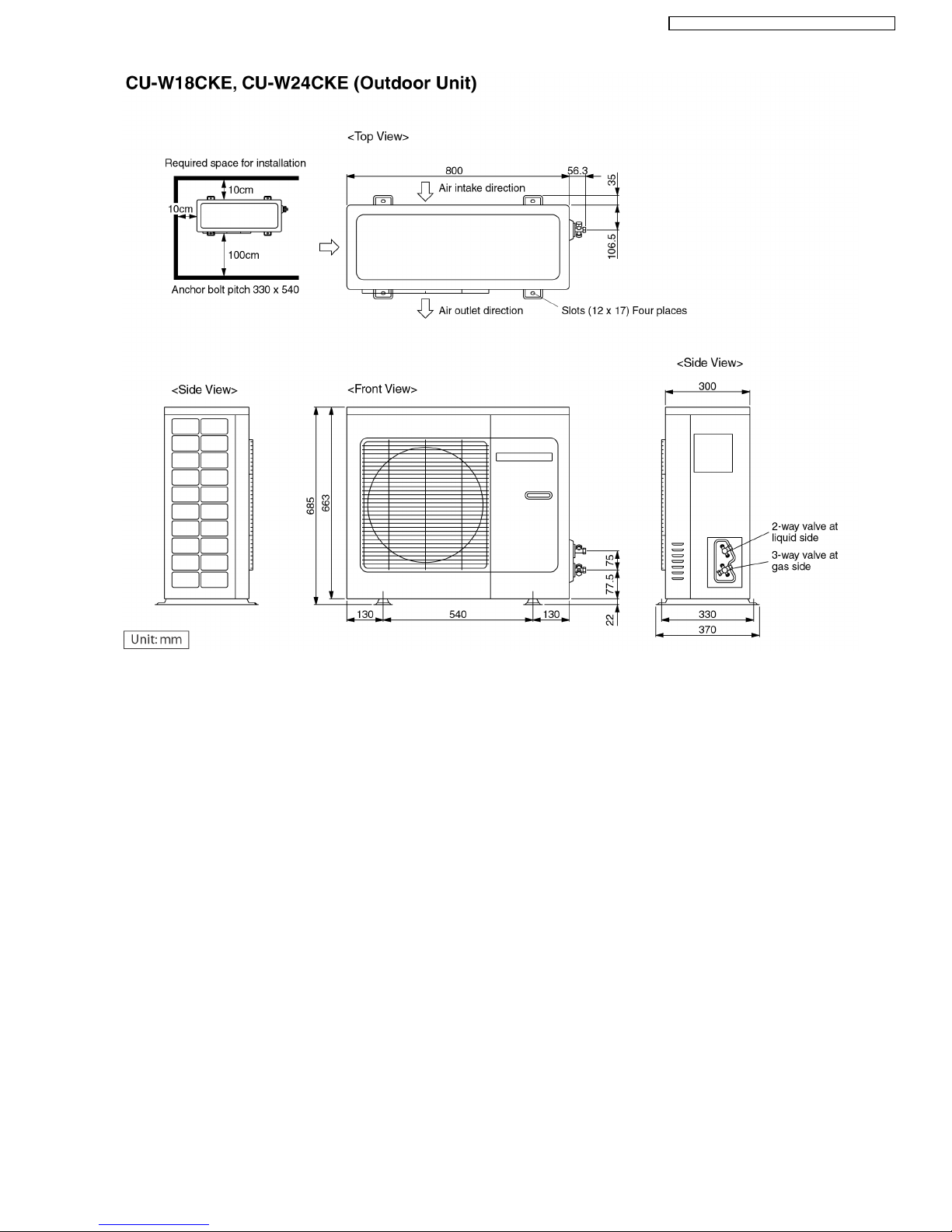
4 Dimensions
10
5 Refrigeration Cycle Diagram
12
6 Block Diagram
13
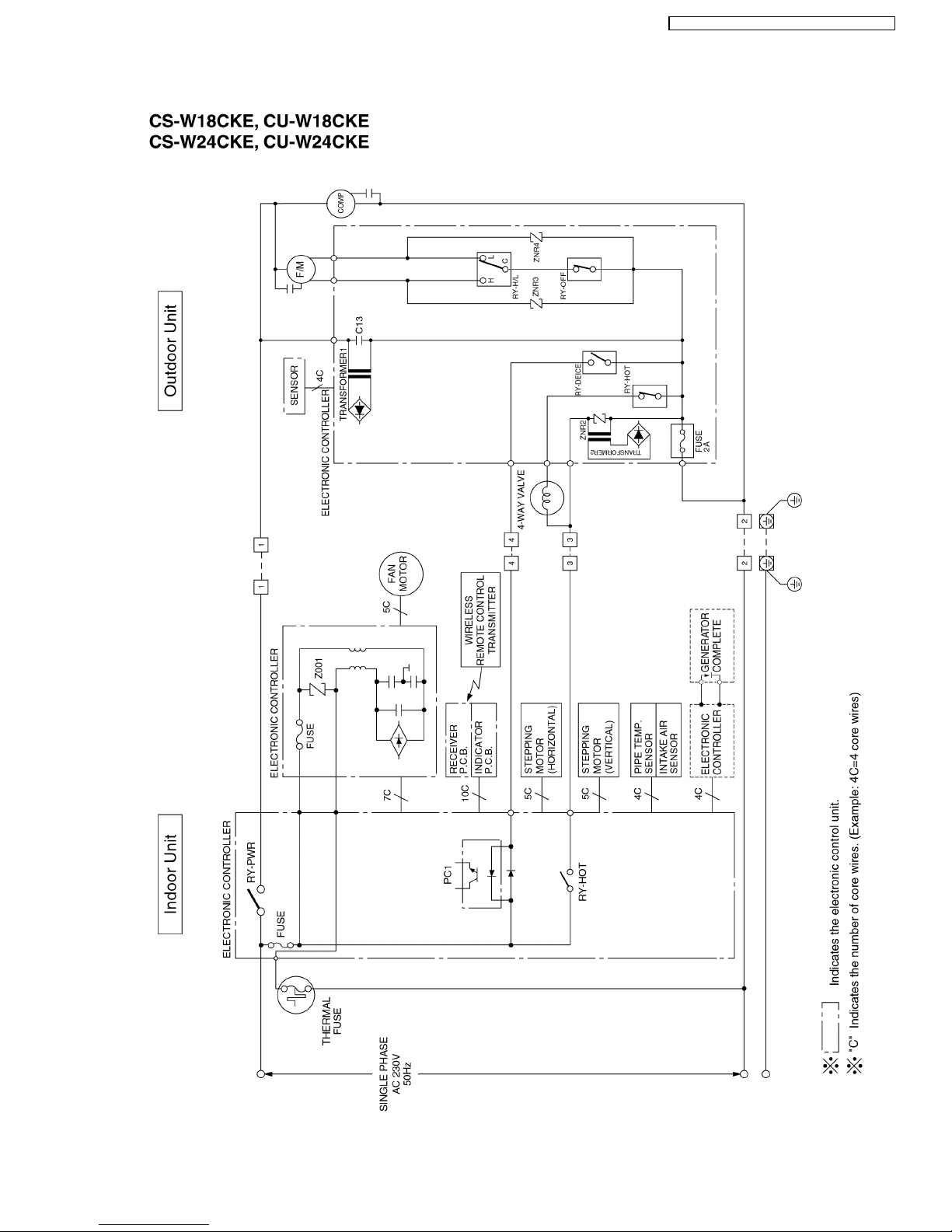
7 Wiring Diagram
14
8 Operation Details
15
8.1. Indoor Fan Speed Control
15
8.2. Cooling Mode Operation
16
8.3. Soft Dry Mode Operation
20
8.4. Heating Mode Operation
22
8.5. Automatic Mode Operation
27
© 2003 Matsushita Industrial Corp. Sdn. Bhd.
(11969-T). All rights reserved. Unauthorized copying
and distribution is a violation of law.
CS-W18CKE CU-W18CKE
CS-W24CKE CU-W24CKE
8.6. Random Auto Restart Control 28
8.7. Airflow Direction Control
28
8.8. Delay ON Timer Control
29
8.9. Remote Control Signal Receiving Sound
29
8.10. Powerful Mode Operation
30
8.11. Ionizer Operation
31
9 Operating Instructions
35
10 Installation Instructions
43
10.1. Safety Precautions
43
10.2. INDOOR UNIT
46
10.3. OUTDOOR UNIT
49
11 Installation and Servicing Air Conditione r Using R410A
53
11.1. OUTLINE
53
Air Conditioner
CONTENTS
Page Page
Order No. MAC0310029C2
11.2. TOOLS FOR INSTALLING/SERVICING REFRIGERANT
PIPING
54
11.3. REFRIGERANT PIPING WORK
58
11.4. INSTALLATION, TRANSFERRING, SERVICING
60
12 Servicing Information
64
12.1. Indoor Electronic Controllers Removal Procedures
64
12.2. Cross Flow Fan Indoor and Fan Motor Removal
Procedures
65
13 Troubleshooting Guide
68
13.1. Refrigeration cycle system
68
14 Technical Data
70
15 Exploded View
74
16 Replacement Parts List
75
17 Exploded View
76
18 Replacement Parts List
77
•
• •
•
High Efficiency
•
• •
•
Compact Design
•
• •
•
Comfort Environment
−
− −
−
Ionizer control for generate negative ion in discharge air
−
− −
−
Air filter with function to reduce dust and smoke
−
− −
−
Wider range of horizontal discharge air
−
− −
−
New Automatic air swing and manual adjusted by
remote control for horizontal airflow.
•
• •
•
Auto Restart
−
− −
−
Random auto restart after power failure for safety restart
operation
•
• •
•
Removable and Washa ble Front Panel
•
• •
•
Remote Control Self-illuminating Button
•
• •
•
Catechin Air Purifying Filter
−
− −
−
Trap dust, tobacco smoke and tiny particles
−
− −
−
Prevent the growth of bacteria and viruses trapped
•
• •
•
Triple Deodorizing Filter
−
− −
−
Absorb odours produced by wall paper, construction
material and living environment
19 Electronic Circuit Diagram 78
19.1. REMOTE CONTROL
84
19.2. PRINT PATTERNINDOOR UNIT PRINTED CIRCUIT
BOARD
TOP VIEW
85
19.3. PRINT PATTERNINDOOR UNIT PRINTED CIRCUIT
BOARD
BOTTOM VIEW
86
19.4. PRINT PATTERNOUTDOOR UNIT PRINTED CIRCUIT
BOARD
87
•
• •
•
Quality Improvement
−
− −
−
Gas leakage protection
−
− −
−
Prevent compressor reverse cycle
−
− −
−
Inner protector
−
− −
−
Noise prevention during soft dry operation.
−
− −
−
Anti-dew Formation Control (Cooling & Soft Dry)
−
− −
−
Overload Protection Control (Heating)
−
− −
−
Outdoor Fan Control
−
− −
−
Compressor High Pressure Control
−
− −
−
Blue Coated Condenser
−
− −
−
High resistance to corrosion.
•
• •
•
Operation Improvement
−
− −
−
Quiet mode to provide quiet operation
−
− −
−
Powerful mode to reach the desired room temperature
quickly
•
• •
•
Long Installation Piping
−
− −
−
Long piping up to 25 meter
•
• •
•
24-hour Timer Setting
•
• •
•
Environmental Friendly
−
− −
−
R410A, which does not contain chlorine, is used as its
refrigerant, so there is no danger of damage to the
ozone layer in stratosphere.
1 Features
2
CS-W18CK E CU-W 18CKE / CS-W24CK E CU-W2 4CKE
2 Functions
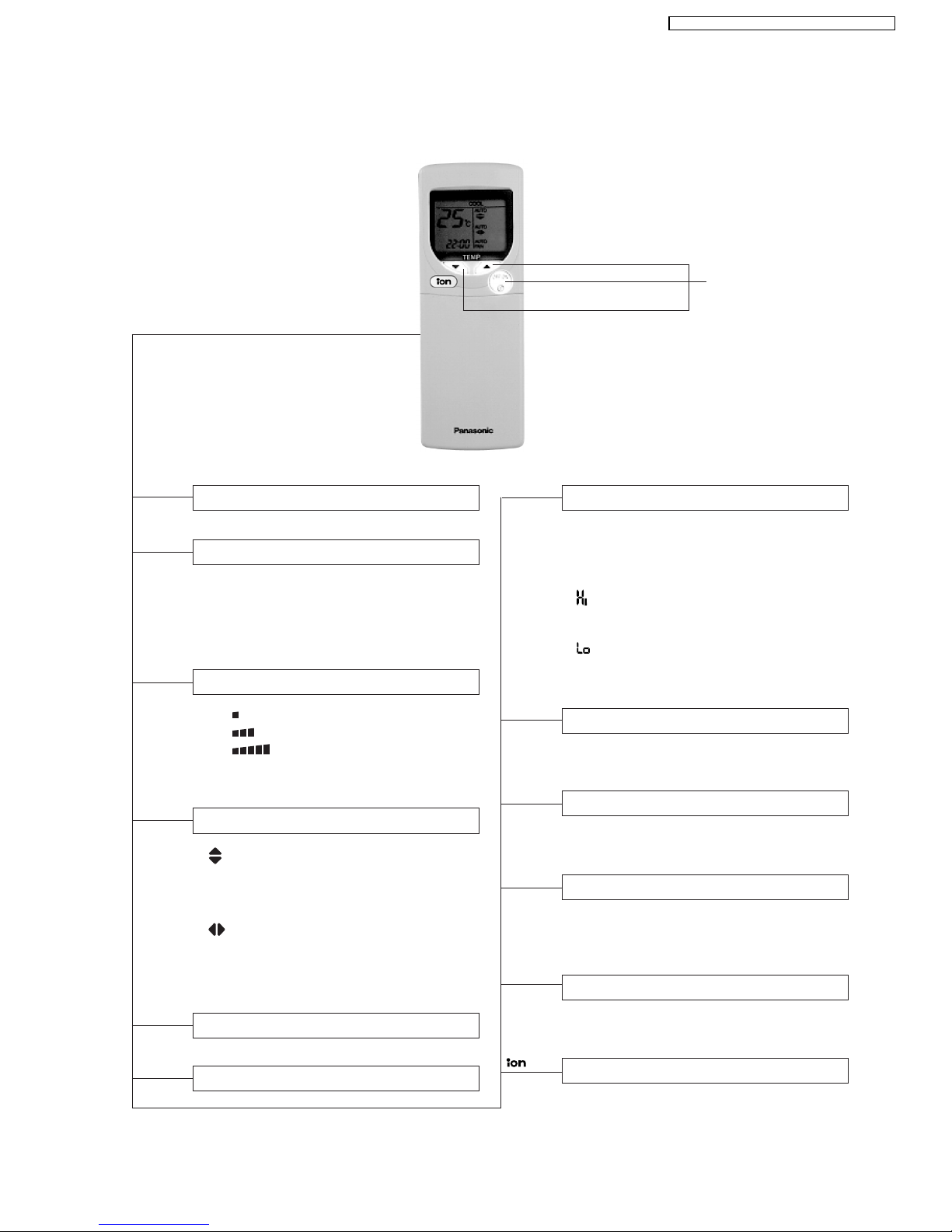
Remote Control
Operation OFF / ON
OFF / ON
Room Temperature Setting
TEMP.
Operation Mode Selection
•
AUTO
Automatic Operation Mode
•
HEAT
Heating Operation Mode
•
COOL
Cooling Operation Mode
•
DRY
Soft Dry Operation Mode
MODE
TIME
Time / Timer Setting
• Hours and minutes setting.
Clock Setting
• Current time setting.
Ionizer Operation OFF / ON
Indoor Fan Speed Selection
FAN SPEED
•
FAN
Low Fan Speed
•
FAN
Medium Fan Speed
•
FAN
High Fan Speed
•
AUTO
Automatic Fan Speed
FAN
Vertical Airflow Direction Control
• 24-hour, OFF / ON Real Timer Setting.
ON-TIMER
OFF-TIMER
Timer Operation Selection
SET
CANCEL
Timer Operation Set / Cancel
• ON Timer and OFF Timer setting and
cancellation.
CLOCK
AIR SWING
• Vertical Automatic Airflow
Direction Control and Manual
Airflow Direction Control (5
stages of adjustment).
•
Horizontal Automatic Airflow
Direction Control and Manual
Airflow Direction Control (5
stages of adjustment).
Powerful Mode Operation OFF/ON
POWERFUL
Quiet Mode Operation OFF/ON
QUIET
Heating, Cooling, Soft Dry Operation.
• Temperature Setting (16°C to 30°C)
Automatic Operation
•
Operation with 2°C higher than
standard temperature.
• Operation with standard temperature.
•
Operation with 2°C lower than
standard temperature.
Self illuminating
button
3
CS-W18CK E CU-W 18CKE / CS-W24CK E CU-W24 CKE
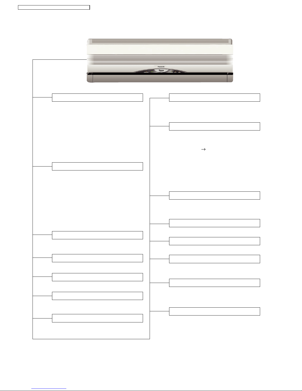
Indoor Unit
Ionizer Control
• Ionizer control for generate negative ion
in discharge air.
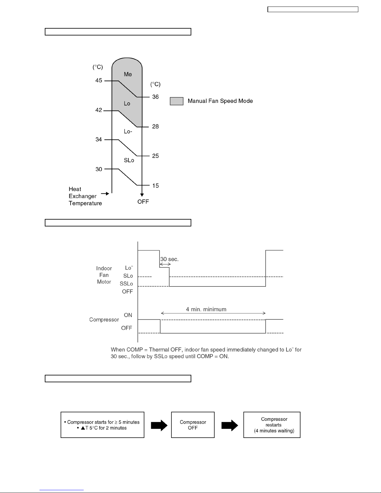
Indoor Fan Speed Control
• High, Medium and Low.
• Automatic Fan Speed Mode
– Heating : Fan speed varies from Me
SSLo in accordance with
indoor heat exchanger.
– Cooling : Fan rotates at Hi, Me and
Lo- speed. Deodorizing
control is available.
– Soft Dry : Fan rotates at Lo- speed.
Deodorizing control is
available.
• Automatic air swing and manual adjusted
by remote control for vertical and horizontal
airflow.
Airflow Direction Control
Automatic Operation Button
• Press for < 5s to operate Automatic
operation mode.
(Used when the remote control cannot be used.)
• Press continuously for 5s or < 10s to
operate Test Run/Pump down. “Beep”
sound will be heard at the 5th second.
(Used when test running or servicing.)
• Press continuously for 10s and above to
omit or resume the remote control signal
receiving sound. “Beep, beep” sound will
be heard at the 10th second.
AUTO
OFF / ON
Operation Indication Lamps (LED)
•
POWER
(Green).......... Lights up in operation,
blinks in Automatic
Operation Mode judging
and Hot Start operation.
•
QUIET
(Orange) ......... Lights up in Quiet Mode
Operation.
•
TIMER
(Orange) .........
Lights up in Timer Setting.
•
POWERFUL
(Orange) ...Lights up in Powerful
Mode Operation.
•
ION
(Green) ...... Lights up in Ionizer
Mode Operation.
Operation Mode
• Heating, Cooling, Soft Dry and Automatic
Mode.
Powerful Operation
•
Reaches the desired room temperature quickly.
Time Delay Safety Control
• Restarting is inhibited for appro. 3 minutes.
Quiet Operation
• To provide quiet operation.
7 Minutes Time Save Control
• Cooling Operation only.
Anti-Dew Formation Control
• Anti-Dew Formation Control for indoor unit
discharge area.
Random Auto Restart Control
• Operation is restarted randomly after
power failure at previous setting mode.
Anti-Freezing Control
• Anti-Freezing control for indoor heat
exchanger. (Cooling and Soft Dry)
Hot-Start Control
• At Heating Operation the indoor fan will
operate at SLo speed when indoor heat
exchanger temperature reaches 30°C.
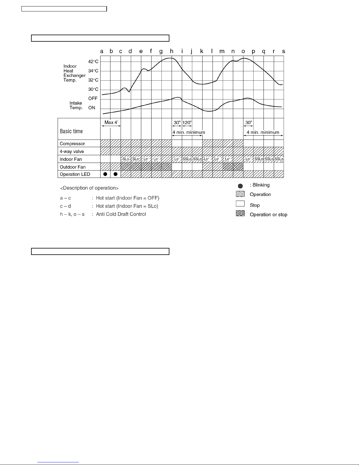
Anti Cold Draft Control
• The indoor fan operates at Lo– (30 sec.)
after that SSLo when the indoor heat
exchanger temperature is low.
(During Heating mode thermal off)
4
CS-W18CK E CU-W 18CKE / CS-W24CK E CU-W2 4CKE

Outdoor Unit
• To protect compressor from reverse
rotation when there is an instantaneous
power failure.
60 Secs. Forced Operation Control
• Once the compressor is activated, it
does not stop within the first 60 secs.
However, it stops immediately with
remote control stop signal.
Overload Protector
• Inner protector.
Compressor Reverse Rotation
Protection Control
Outdoor Fan Operation Control
• 6-pole induction motor (2 speed).
• For Cooling or Soft Dry operation
Hi-speed ............. When outdoor
temperature reaches to 31°C.
Lo-speed ............. When outdoor
temperature reaches to 29°C.
• For Heating operation
Hi-speed ............. When outdoor
temperature reaches to 13.5°C.
Lo-speed ............. When outdoor
temperature reaches to 15.5°C.
• For Over-heating Protection, the Fan is
switched ON or OFF depending on the
piping temperature and the outdoor
temperature.
Deice Control
• To prevent frosting at outdoor heat
exchanger during Heating Operation.
4-Way Valve Control
• When the unit is switched to “OFF”
during Heating Operation, 4-way valve
stays at Heating position for 5 minutes.
5
CS-W18CK E CU-W 18CKE / CS-W24CK E CU-W24 CKE
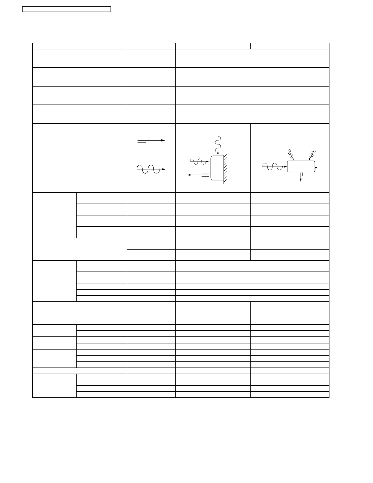
3 Product Specifications
Unit CS-W18CKE CU-W18CKE
Power Source Phase, Voltage, Cycle Single, 230, 50 Hz
Cooling Capacity kW (BTU/h) 5.30 (18,100)
Heating Capacity kW (BTU/h) 5.55 (18,900)
Moisture Removal l/h (Pint/h) 2.9 (6.1)
Airflow Method OUTLET
INTAKE
SIDE VIEW TOP VIEW
Air Volume Indoor Air (Lo) m3/min (cfm) Cooling; 13.3 (470)
Heating; 14.2 (500)
25.6 (904)
Indoor Air (Me) m3/min (cfm) Cooling; 14.8 (520)
Heating; 14.8 (520)
—
Indoor Air (Hi) m3/min (cfm) Cooling; 15.6 (550)
Heating; 16.4 (580)
40.0 (1,410)
Indoor Air (SHi) m3/min (cfm) Cooling; 16.4 (580)
Heating; 16.4 (580)
—
Noise Level dB (A) Cooling; High 43, Low 38
Heating; High 42, Low 38
Cooling; High 55
Heating; High 56
Power level dB Cooling; 55
Heating; 53
Cooling; 68
Heating; 69
Electrical Data Input Power kW Cooling; 1.65
Heating; 1.70
Running Current A Cooling; 7.4
Heating; 7.6
EER W/W (BTU/hW) Cooling; 3.21 (10.95)
COP W/W (BTU/hW) Heating; 3.26 (11.13)
Starting Current A 27.0
Piping Connection Port
(Flare piping)
inch
inch
G ; Half Union 1/2”
L ; Half Union 1/4”
G ; 3-way valve 1/2”
L ; 2-way valve 1/4”
Pipe Size
(Flare piping)
inch
inch
G ; (gas side) 1/2”
L ; (liquid side) 1/4”
G ; (gas side) 1/2”
L ; (liquid side) 1/4”
Drain
Hose
Inner diameter mm 12 —
Length mm 650 —
Power Cord Length m 1.9 —
Number of core-wire 3 (1.5 mm2) —
Dimensions Height inch (mm) 10 - 13/16 (275) 26 - 31/32 (685)
Width inch (mm) 39 - 9/32 (998) 31 - 1/2 (800)
Depth inch (mm) 8 - 9/32 (210) 11 - 13/16 (300)
Net Weight lb (kg) 24 (11.0) 121 (55.0)
Compressor Type — Rotary (1 cylinder)
rolling piston type
Motor Type — Induction (2-poles)
Rated Output kW — 1.4
6
CS-W18CK E CU-W 18CKE / CS-W24CK E CU-W2 4CKE
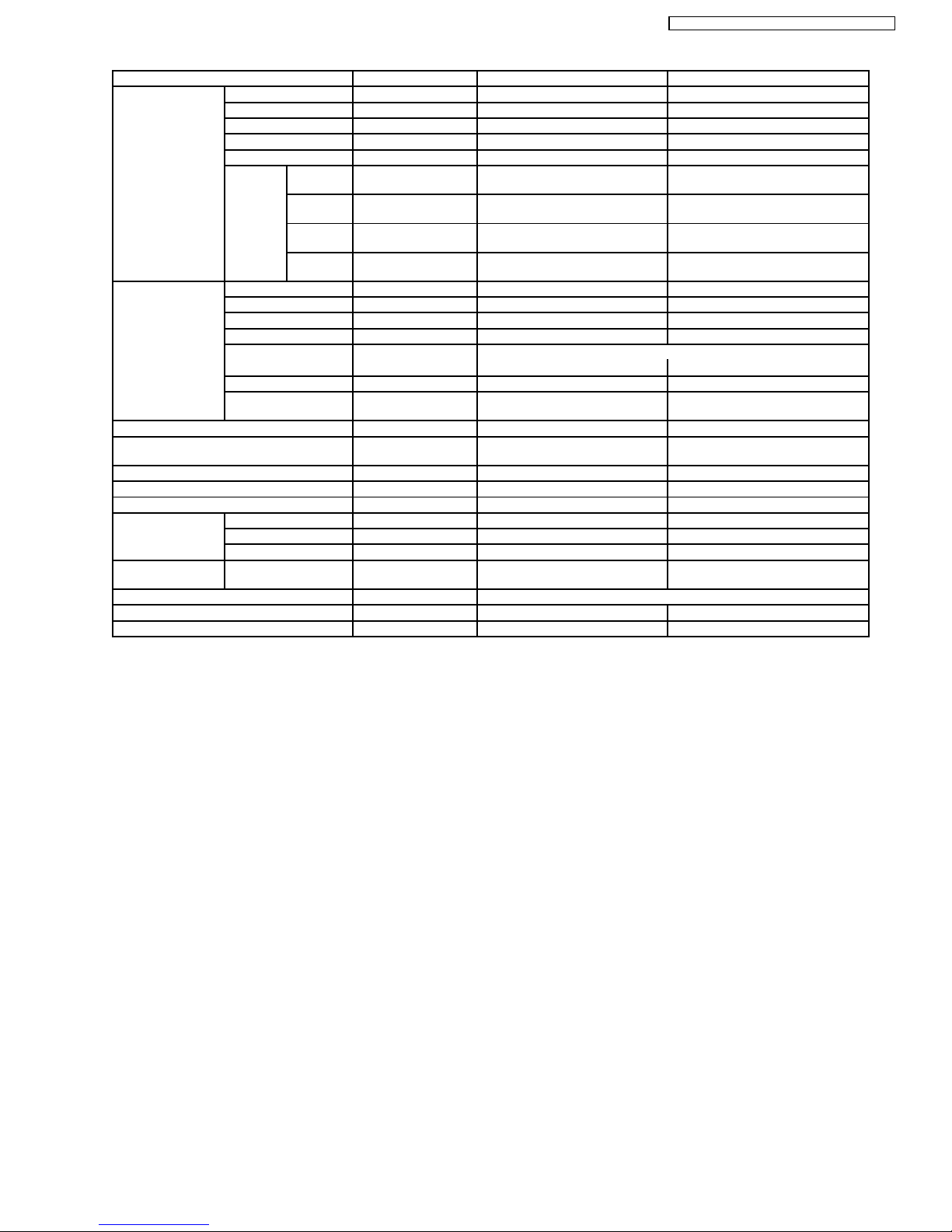
Unit CS-W18CKE CU-W18CKE
Air Circulation Type Cross-flow Fan Propeller Fan
Material ASHT-18 PP
Motor Type Transistor (8-poles) Induction (4-poles)
Input W 53.5 130
Rated Output W 30 67
Fan Speed Low rpm Cooling; 1,160
Heating; 1,240
640
Medium rpm Cooling; 1,290
Heating; 1,290
—
High rpm Cooling; 1,380
Heating; 1,440
1,000
SuperHigh rpm Cooling; 1,440
Heating; 1,440
—
Heat Exchanger Description Evaporator Condenser
Tube material Copper Copper
Fin material Aluminium (Pre Coat) Aluminium (Blue Coat)
Fin Type Slit Fin Corrugated Fin
Row / Stage (Plate fin configuration, forced draft)
2×15 2×26
FPI 21 16
Size (W × H × L) mm 810 × 315 × 25.4 769.2
732.9
× 660.4 × 44
Refrigerant Control Device — Capillary Tube
Refrigeration Oil (cm3) — RB68A OR FRE0L ALPHA 68M
(670)
Refrigerant (R410A) g (oz) — 1,620 (57.2)
Thermostat Electronic Control Electronic Control
Protection Device — Inner Protector
Capillary Tube Length mm — Cooling; 1,180, Heating; 1,048
Flow Rate l/min — Cooling; 8.7, Heating; 14.0
Inner Diameter mm — Cooling; 1.5, Heating; 1.8
Air Filter Material
Style
P.P.
Honeycomb
—
Capacity Control Capillary Tube
Compressor Capacitor µF, VAC — 50 µF, 370VAC
Fan Motor Capacitor µF, VAC — 3.0 µF, 450VAC
Note:
•
• •
•
Specifications are subject to change without notice for further improvement.
7
CS-W18CK E CU-W 18CKE / CS-W24CK E CU-W24 CKE
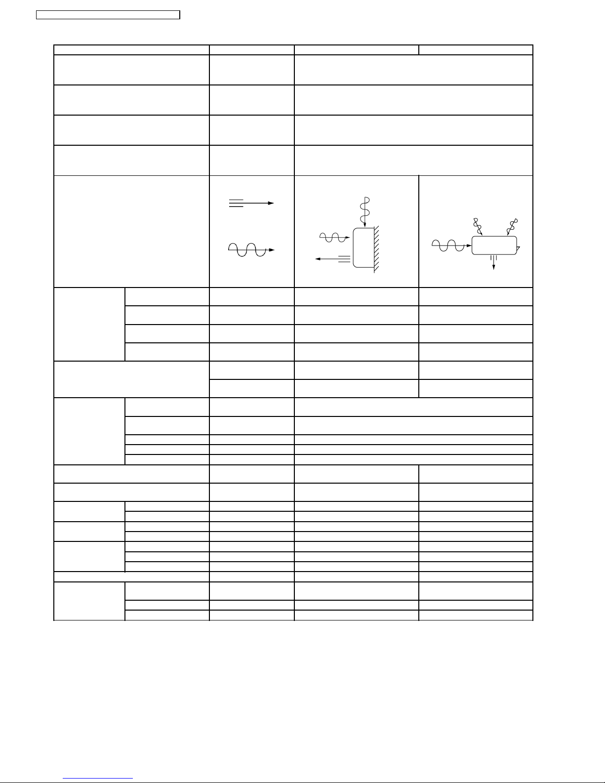
Unit CS-W24CKE CU-W24CKE
Power Source Phase, Voltage, Cycle Single, 230, 50 Hz
Cooling Capacity kW (BTU/h) 7.03 (24,000)
Heating Capacity kW (BTU/h) 7.72 (26,300)
Moisture Removal l/h (Pint/h) 4.0 (8.5)
Airflow Method OUTLET
INTAKE
SIDE VIEW TOP VIEW
Air Volume Indoor Air (Lo) m3/min (cfm) Cooling; 14.4 (510)
Heating; 15.6 (550)
27.4 (970)
Indoor Air (Me) m3/min (cfm) Cooling; 16.4 (580)
Heating; 16.4 (580)
—
Indoor Air (Hi) m3/min (cfm) Cooling; 17.5 (620)
Heating; 18.1 (640)
47.2 (1,670)
Indoor Air (SHi) m3/min (cfm) Cooling; 18.1 (640)
Heating; 18.1 (640)
—
Noise Level dB (A) Cooling; High 47, Low 41
Heating; High 46, Low 41
Cooling; High 60
Heating; High 61
Power level dB Cooling; 59
Heating; 57
Coolling; 74
Heating; 74
Electrical Data Input Power kW Cooling; 2.78
Heating; 2.69
Running Current A Cooling; 13.1
Heating; 12.9
EER W/W (BTU/hW) Cooling; 2.53 (8.63)
COP W/W (BTU/hW) Heating; 2.87 (9.79)
Starting Current A 65.0
Piping Connection Port
(Flare piping)
inch
inch
G ; Half Union 5/8”
L ; Half Union 1/4”
G ; 3-way valve 5/8”
L ; 2-way valve 1/4”
Pipe Size
(Flare piping)
inch
inch
G ; (gas side) 5/8”
L ; (liquid side) 1/4”
G ; (gas side) 5/8”
L ; (liquid side) 1/4”
Drain
Hose
Inner diameter mm 12 —
Length mm 650 —
Power Cord Length m 1.9 —
Number of core-wire 3 (2.5 mm2) —
Dimensions Height inch (mm) 10 - 13/16 (275) 26 - 31/32 (685)
Width inch (mm) 39 - 9/32 (998) 31 - 1/2 (800)
Depth inch (mm) 8 - 9/32 (210) 11 - 13/16 (300)
Net Weight lb (kg) 24 (11.0) 135 (61.0)
Compressor Type — Rotary (1 cylinder) rolling piston
type
Motor Type — Induction (2-poles)
Rated Output kW — 2.2
8
CS-W18CK E CU-W 18CKE / CS-W24CK E CU-W2 4CKE
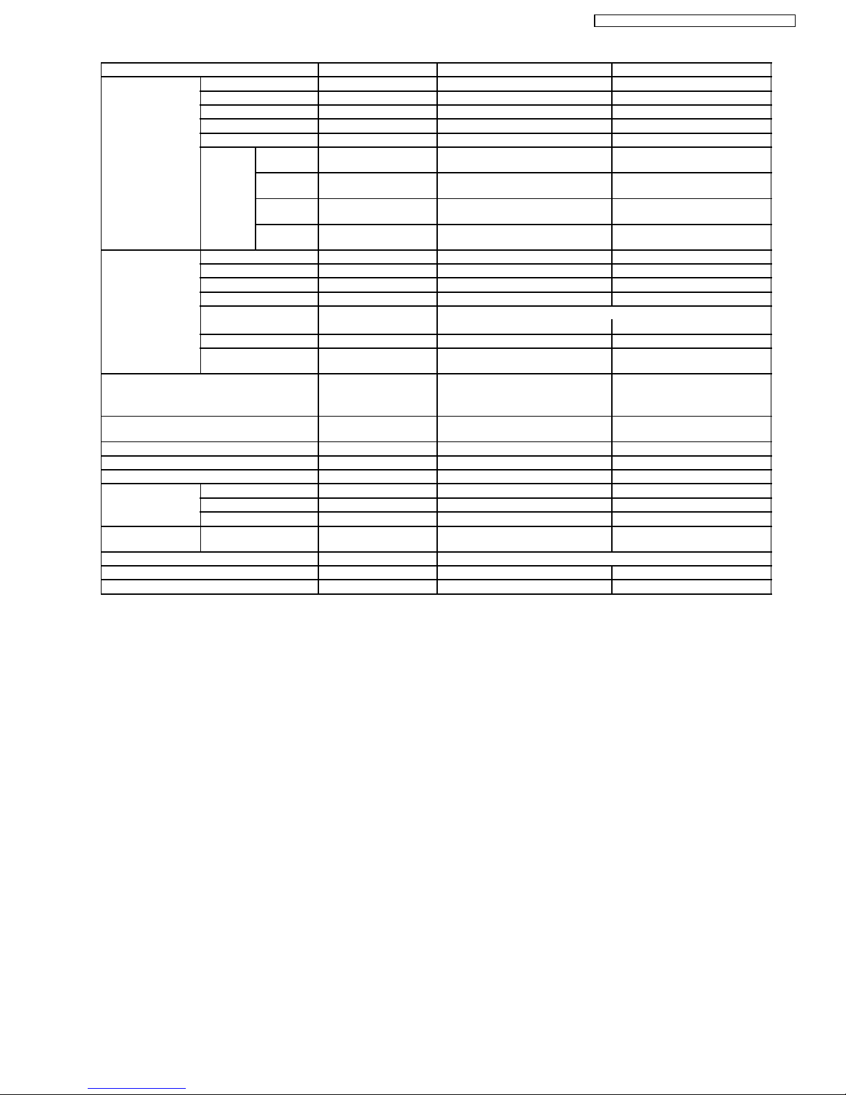
Unit CS-W24CKE CU-W24CKE
Air Circulation Type Cross-flow Fan Propeller Fan
Material ASHT-18 PC + AES + Glass Fiber 15%
Motor Type Transistor (8-poles) Induction (4-poles)
Input W 53.5 190.0
Rated Output W 30 108
Fan Speed Low rpm Cooling; 1,260
Heating; 1,360
680
Medium rpm Cooling; 1,430
Heating; 1,430
—
High rpm Cooling; 1,530
Heating; 1,580
1,170
SuperHigh rpm Cooling; 1,580
Heating; 1,580
—
Heat Exchanger Description Evaporator Condenser
Tube material Copper Copper
Fin material Aluminium (Pre Coat) Aluminium (Blue Coat)
Fin Type Slit Fin Corrugated Fin
Row / Stage (Plate fin configuration, forced draft)
2×15 2×26
FPI 21 16
Size (W × H × L) mm 810 × 315 × 25.4 769.2
732.9
× 660.4 × 44.0
Refrigerant Control Device — Capillary Tube
Refrigeration Oil (cm3) — RB68A OR FRE0L ALPHA 68M
(1,130)
Refrigerant (R410A) g (oz) — 1,780 (62.8)
Thermostat Electronic Control Electronic Control
Protection Device — Inner Protector
Capillary Tube Length mm — Cooling; 663, Heating; 550
Flow Rate l/min — Cooling; 13.0, Heating; 29.0
Inner Diameter mm — Cooling; 1.6, Heating; 2.4
Air Filter Material
Style
P.P.
Honeycomb
—
Capacity Control Capillary Tube
Compressor Capacitor µF, VAC — 45 µF, 370VAC
Fan Motor Capacitor µF, VAC — 3.0 µF, 450VAC
Note:
•
• •
•
Specifications are subject to change without notice for further improvement.
9
CS-W18CK E CU-W 18CKE / CS-W24CK E CU-W24 CKE
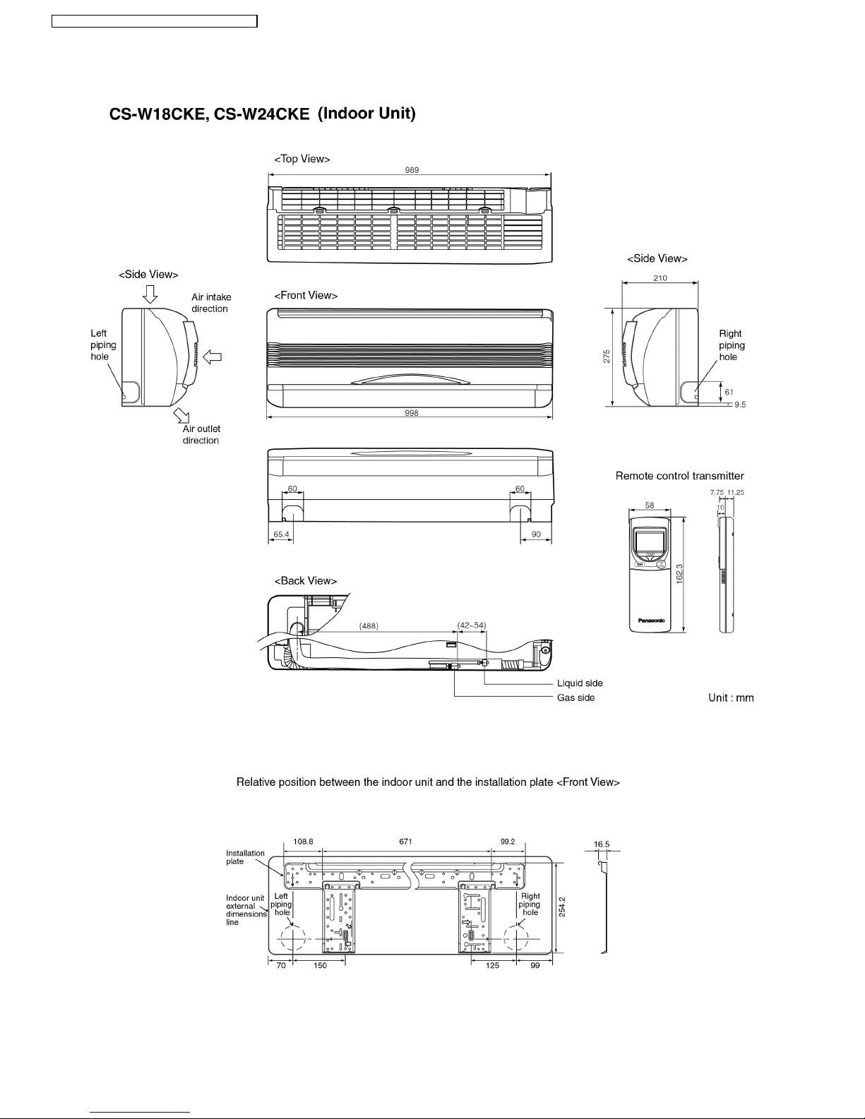
4 Dimensions
10
CS-W18CK E CU-W 18CKE / CS-W24CK E CU-W2 4CKE
11
CS-W18CK E CU-W 18CKE / CS-W24CK E CU-W24 CKE
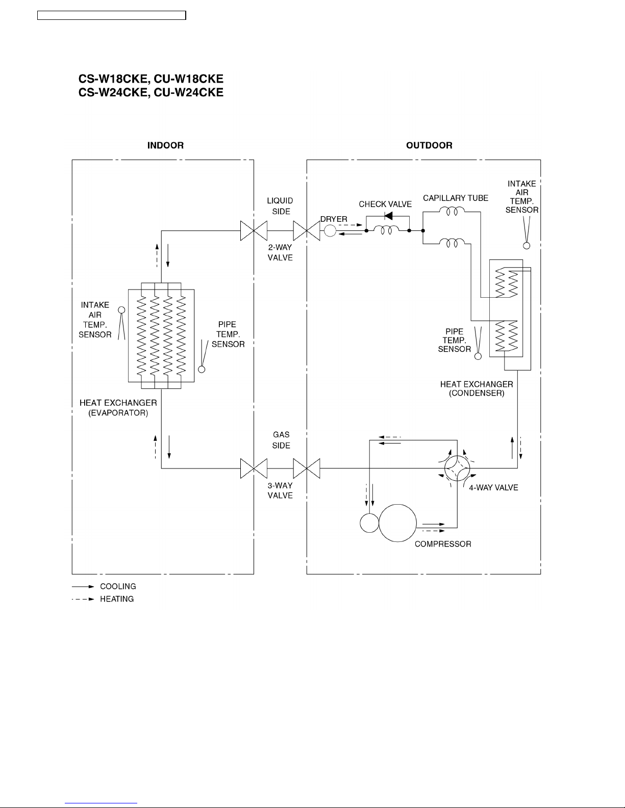
5 Refrigeration Cycle Diagram
12
CS-W18CK E CU-W 18CKE / CS-W24CK E CU-W2 4CKE
6 Block Diagram
13
CS-W18CK E CU-W 18CKE / CS-W24CK E CU-W24 CKE
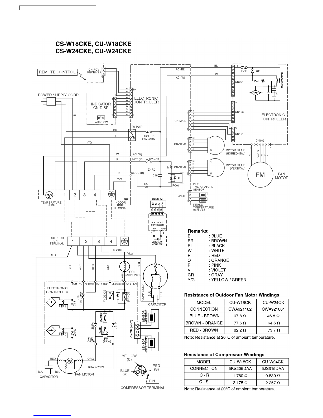
7 Wiring Diagram
CS-W18CK E CU-W 18CKE / CS-W24CK E CU-W2 4CKE
14
8 Operation Details
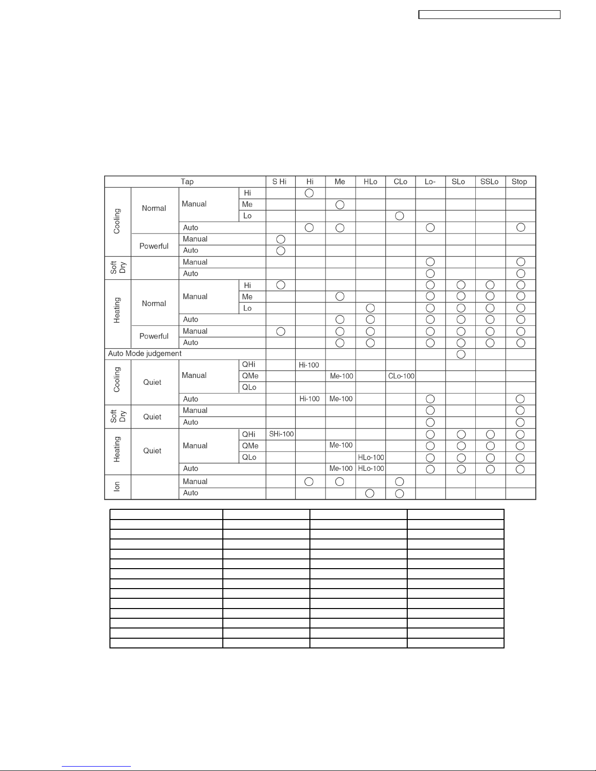
8.1. Indoor Fan Speed Control
•
• •
•
Auto Fan Speed Control
When set to Auto Fan Speed, the fan speed is adjusted between maximum and minimum setting as shown in the table.
•
• •
•
Manual Fan Speed Control
Basic fan speed adjustment (3 settings, from Lo to Hi) can be carried out by using the Fan Speed selection button at the remote
control.
Speed COOL, DRY Heat CS-W24CKE CS-W18CKE
SHi Hi 1580 1440
Hi 1530 1380
Me Me 1430 1290
Lo+ Lo 1360 1240
Lo 1260 1160
Lo- Lo- 1070 980
SLo SLo 830 760
SS Lo SS Lo 300 300
Q SHi QHi 1480 1340
QHi 1430 1280
QMe QMe 1330 1190
QLo 1260 1140
QLo 1160 1060
15
CS-W18CK E CU-W 18CKE / CS-W24CK E CU-W24 CKE

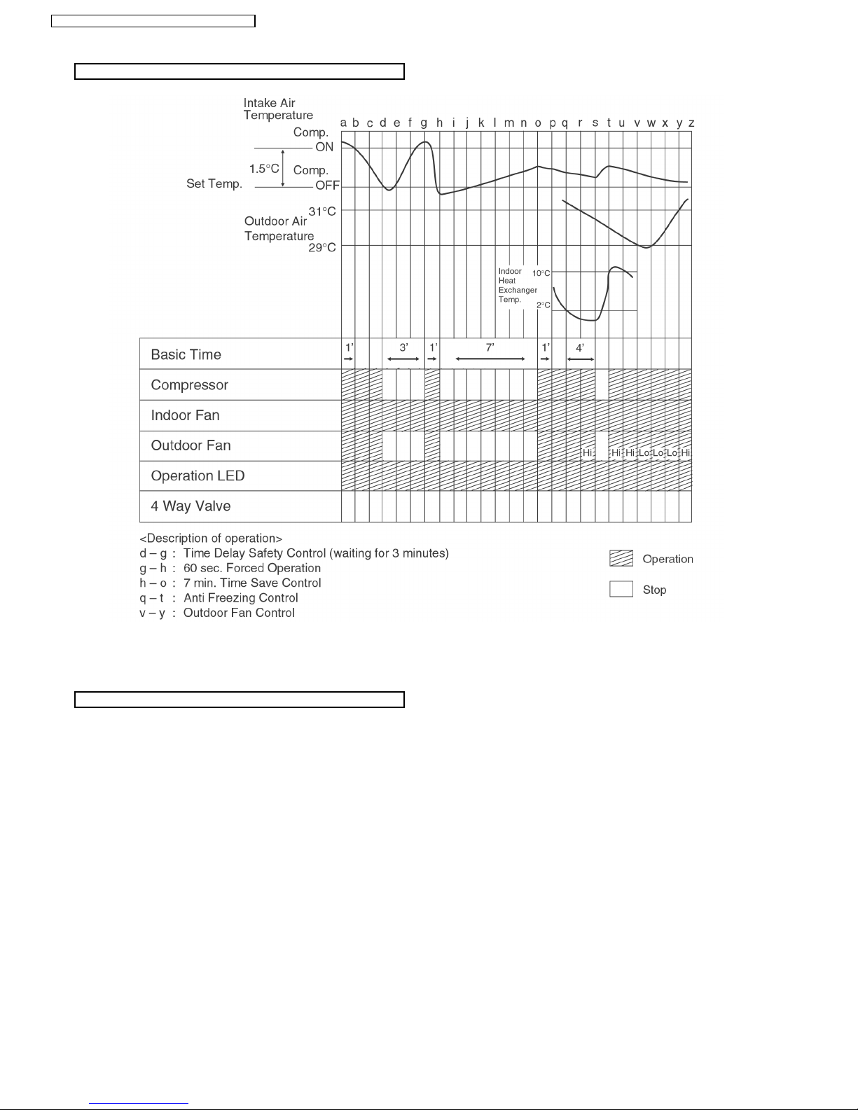
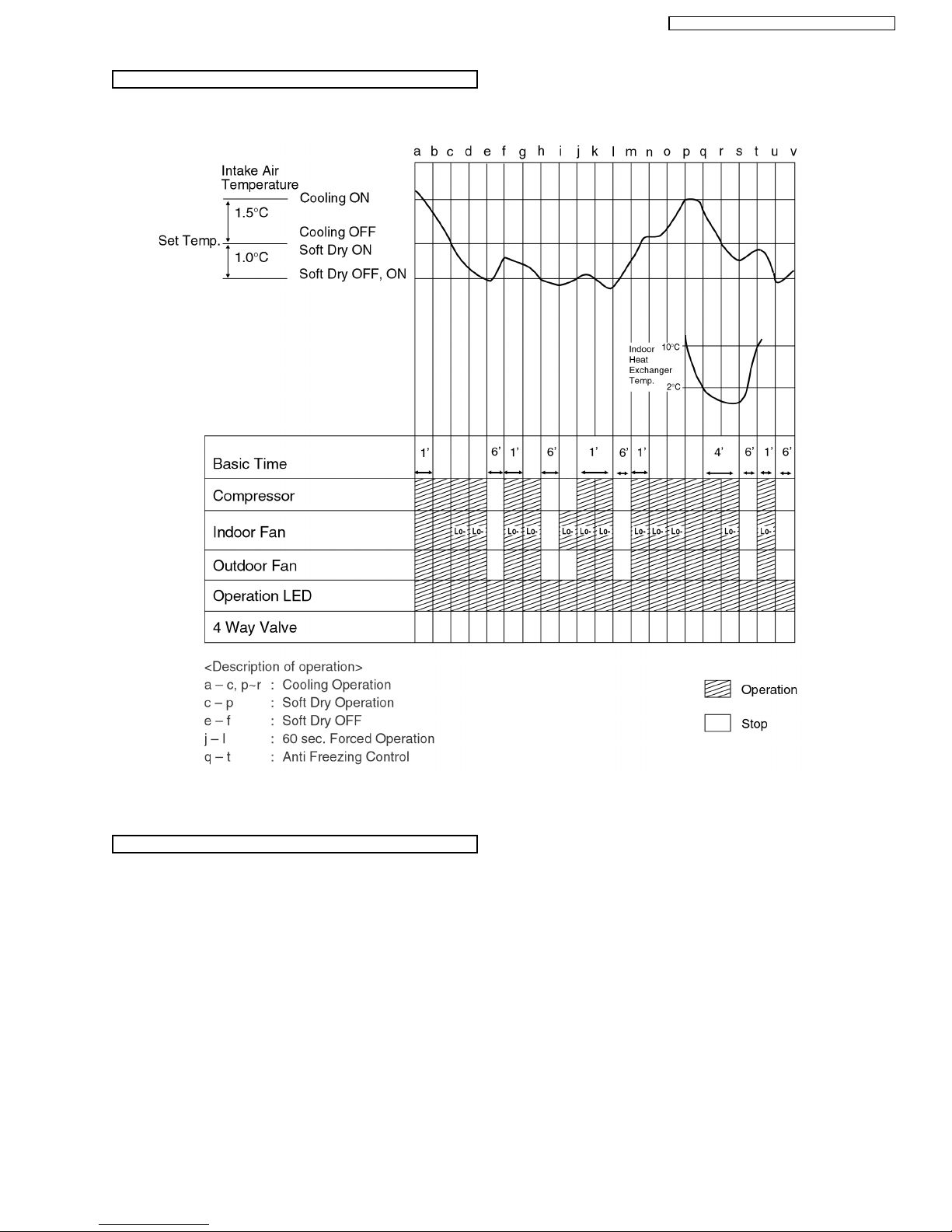
Cooling in operation according to Remote Control setting.
Time Delay Safety Control (3 minutes)
7 minutes Time Save Control
Anti-Freezing Control
•
• •
•
If the temperature of the indoor heat exchanger falls
continuously below 2°C for 4 minute s or more, the
compressor turns off to protect the indoor heat exchanger
from freezing. The fan speed setting remains the same.
•
• •
•
Compressor will restart again when the indoor heat
exchanger temperature rises to 10°C (Recovery).
3 minutes waiting of Time Delay Safety Control is valid for
Cooling Operation.
Compressor Reverse Rotation Protection Control
Anti-Dew Formation Control
8.2. Cooling Mode Operation
•
• •
•
When the compressor is stopped by Remote Control, it restarts after 3 minutes when the Remote Control is turned ON.
•
• •
•
When the setting temperature is reached during cooling operation, the compressor stops and it will not start for 3 minutes.
•
• •
•
The compressor will start automatically if it has stopped for 7 minutes even if the room temperature is between the compressor
ON temperature and OFF temperature.
•
• •
•
If the compressor is operating continuously for 5 minutes or longer and the temperature difference between intake air and
indoor heat exchanger is 2.5°C or less for 2 minutes, compressor will stop and restart automatically.
(Time Delay Safety Control is valid)
!
T = Intake air temperature - Indoor heat exchan ger temperature
This is to protect reverse rotation of the compressor when there is an instantaneous power failure.
•
• •
•
Purpose is to prevent dew formation on indoor unit air discharge area.
•
• •
•
When room temperature is constant (±1°C) the following conditions occur for 30 minutes continuously, anti-dew formation will
activate:
−
− −
−
Indoor intake air temperature is more than 24°C and less than 30°C.
−
− −
−
Remote Control setting temperature is less than 25°C.
−
− −
−
Compressor is on.
−
− −
−
Cooling operation mode.
−
− −
−
Indoor Fan motor operate at Low fan speed or QLo.
•
• •
•
This control is cancelled immediately when above condition is changed.
•
• •
•
Anti-Dew formation is control by:
1. Lo fan speed
Lo fan is changed to Lo+ fan
16
CS-W18CK E CU-W 18CKE / CS-W24CK E CU-W2 4CKE
Automatic Fan Speed Mode
2. QLo fan speed (Transistor Motor)
3. QLo fan speed (Induction Motor)
When Automatic Fan Speed is selected at Remote Control during cooling operation.
•
• •
•
Fan speed rotates in the range of Hi to Me.
•
• •
•
Deodorizing Control.
17
CS-W18CK E CU-W 18CKE / CS-W24CK E CU-W24 CKE
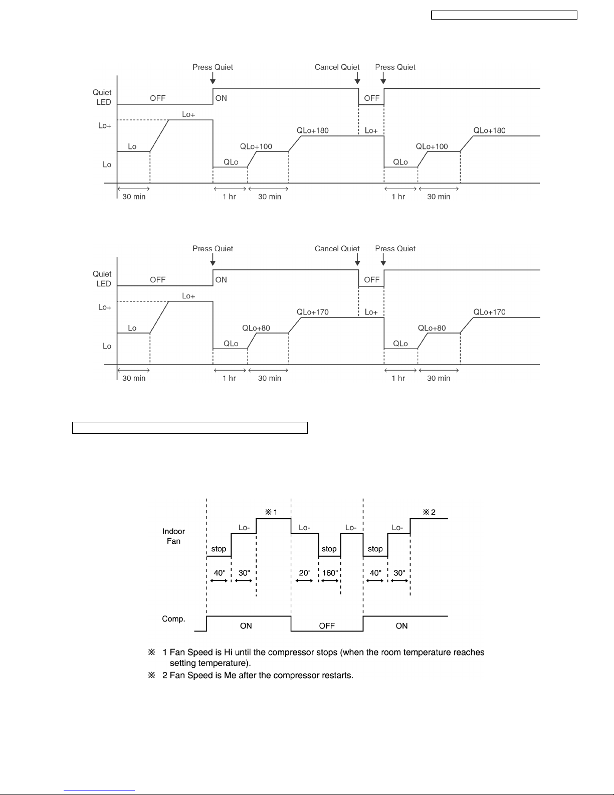
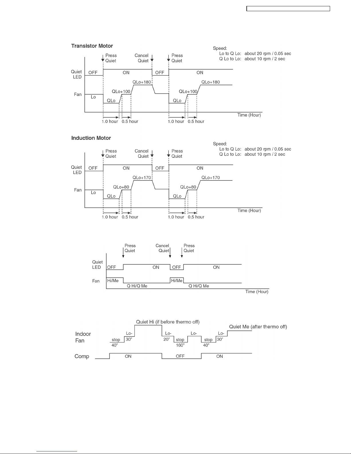
Cooling Operation Time Diagram
Quiet Operation Control
(For Cooling Mode or cooling region of Soft Dry Mode)
•
• •
•
Purpose of this operation is to provide quite cooling operation compare to normal operation.
•
• •
•
When the Quiet Mode is set at the remote control, Quiet Mode LED illuminates, the sound level will be automatically decreased
3 dB, against the present sound level operation.
•
• •
•
Quiet setting of fan speed rpm refer to Indoor Fan Speed Control.
•
• •
•
Dew formation become severe at Quiet Lo cool, therefore:
i) For Transistor Motor
Quiet Lo Cool is operated only 1h 30 minute (1h QLo, 30 min QLo+100). After that, it goes back to QLo+180 rpm. (However
quiet LED remains on).
ii) For Induction Motor
Quiet Lo Cool is operated only 1h 30 minute (1h QLo, 30 min QLo+80). After that, it goes back to QLo+170 rpm. (However quiet
LED remains on).
18
CS-W18CK E CU-W 18CKE / CS-W24CK E CU-W2 4CKE
•
• •
•
Manual Fan Speed:-
−
− −
−
RPM control during Lo cool
−
− −
−
RPM control during Hi & Me cool
•
• •
•
Auto Fan Speed:-
•
• •
•
Quiet Mode Operation will stop if:-
−
− −
−
Quiet mode button is pressed again.
−
− −
−
Stopped by ON/OFF switch.
−
− −
−
Timer OFF activates.
−
− −
−
Powerful mode button is pressed.
19
CS-W18CK E CU-W 18CKE / CS-W24CK E CU-W24 CKE
Time Delay Safety Control
Anti-Freezing Control
Compressor Reverse Rotation Protection Control
Anti-Dew Formation Control
Automatic Fan Speed Mode
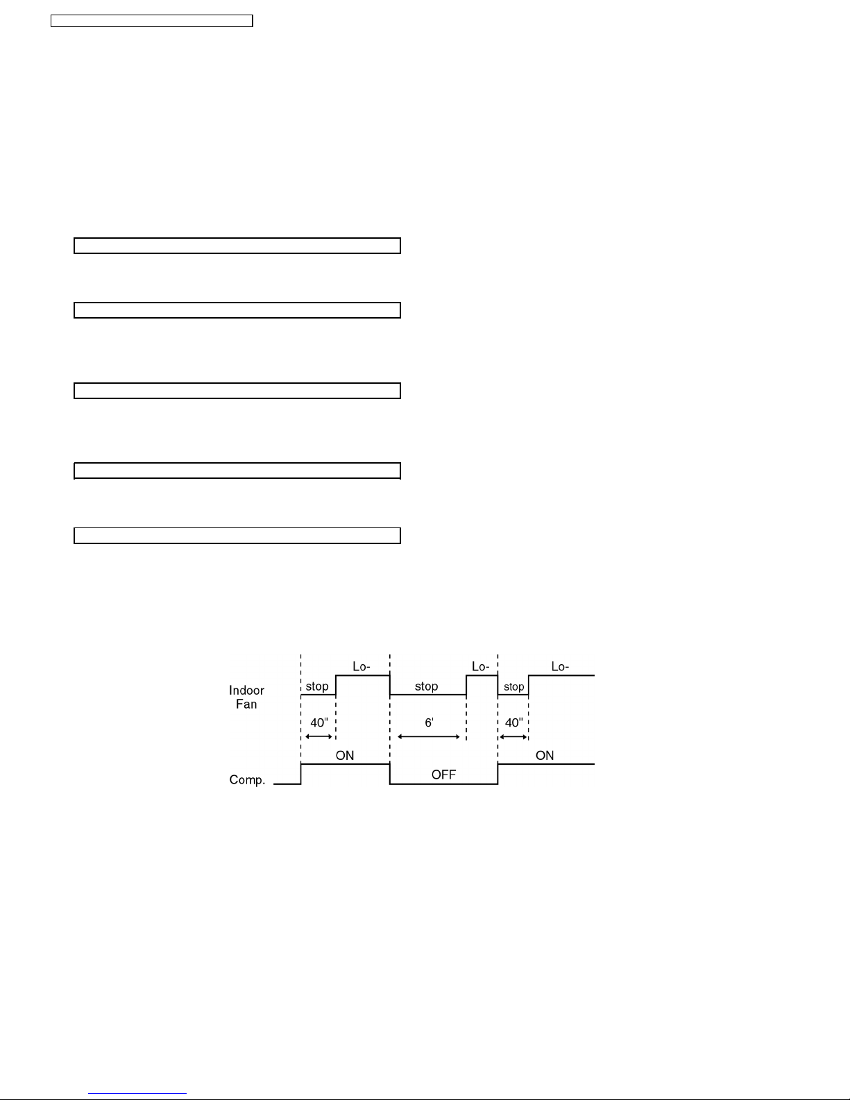
8.3. Soft Dry Mode Operation
•
• •
•
The unit starts cooling operation until the room temperature reaches the setting temperature set on the Remote Control, and
then Soft Dry operation will start.
•
• •
•
During Soft Dry operation, the Indoor Fan will operate at Lo- speed.
•
• •
•
Once room temperature reaches below Soft Dry OFF temperature. Indoor Fan, Compressor and Outdoor Fan stop for 6
minutes.
•
• •
•
Once the compressor stops, it will not start for 3 minutes during Cooling operation.
•
• •
•
Same as Anti-Freezing Control for Cooling Mode operation. (For Soft Dry region, 6 minutes waiting is valid during compressor
stops.)
•
• •
•
Same as Compressor Reverse Rotation Protection Control for Cooling Mode Operation. (For Soft Dry region, 6 minutes waiting
is valid during compressor stops.)
•
• •
•
Same as Anti-Dew Formation Control for Cooling Mode operation.
When Automatic Fan Speed is selected at Remote Control during Soft Dry operation.
•
• •
•
Fan speed off and on at Lo- speed.
•
• •
•
Deodorizing Control.
20
CS-W18CK E CU-W 18CKE / CS-W24CK E CU-W2 4CKE
Soft Dry Operation Time Diagram
Quiet Operation Control
•
• •
•
Same as Quiet Operation Control for Cooling Mode operation.
21
CS-W18CK E CU-W 18CKE / CS-W24CK E CU-W24 CKE
Time Delay Safety Control
Overload Protection Control
4-way Valve Control
Hot Start Control
8.4. Heating Mode Operation
•
• •
•
Heating in operation according to Remote Control setting.
•
• •
•
When the compressor is stopped by Power Switch, Remote Control or there is a power failure, it restarts after 3 minutes when
the Power Switch, Remote Control is turned ON or the power supply is resumed.
•
• •
•
When the setting temperature is reached during heating operation, the compressor stops and it will not start for 4 minutes.
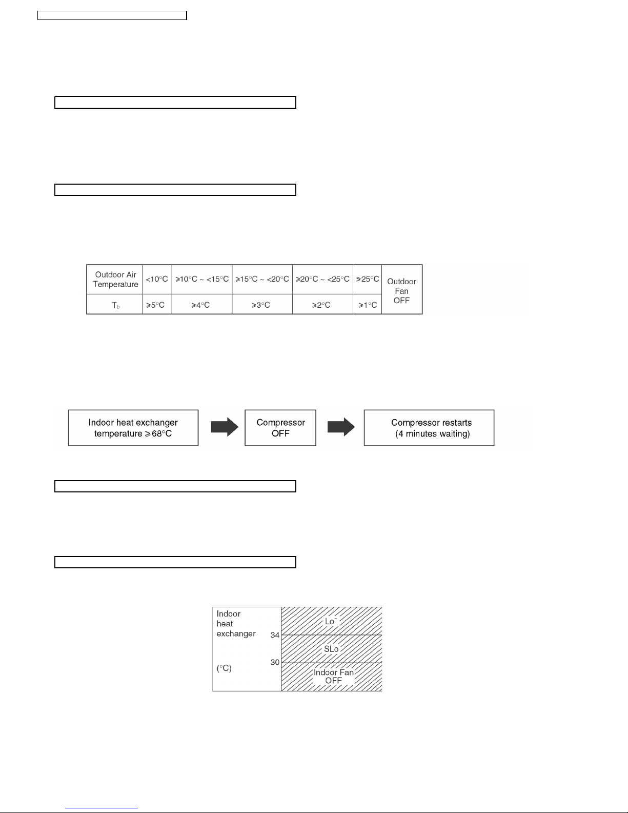
(a) Outdoor Fan Control
•
• •
•
If the temperature of the Outdoor Heat Exchanger less than -3°C, Outdoor Fan is ON. The Outdoor Fan stop, when Outdoor
Heat Exchanger temperature is T
b
or more according to Outdoor Air Temperature region as table below:
The Outdoor Fan restarts when the indoor heat exchan ger temperature falls to 49°C.
During starting of Heating mode and after deice, Outdoor Fan ON for 90 sec. (Hi).
(b) Compressor High Pressure Control
•
• •
•
If the indoor heat exchan ger becomes 68°C or more, the compressor will stop and restart automatically.
(Time Delay Safety Control - 4 minutes waiting).
•
• •
•
4-way valve ON during Heating operation, except deicing operation.
•
• •
•
When the unit is switched to “OFF” during Heating operation, 4-way valve stays at Heating position for 5 minutes.
When Heating operation starts, Indoor Fan will not start until the indoor heat exchanger reaches 30°C as diagram shown.
Hot Start is completed when indoor heat exchanger reaches 42°C.
Maximum Hot start duration = 4 minutes. After 4 minutes,
Hot start operation will be shifted to normal Heating operation.
22
CS-W18CK E CU-W 18CKE / CS-W24CK E CU-W2 4CKE
Automatic Fan Speed Mode
Anti Cold Draft Control
Compressor Reverse Rotation Protection Control
When Automatic Fan Speed is selected at Remote Control during heating operation.
•
• •
•
Fan speed rotates in the range of Me→SLo according to the heat exchanger temperature.
•
• •
•
If the compressor is operating continuously for 5 minutes or longer and the temperature difference between indoor heat
exchanger and intake air is 5°C or less for 2 minutes, compressor will stop and restart automatically.
(Time Delay Safety Control is valid)
!
T = Indoor heat exchanger temperature - Intake air temperature
This is to protect reverse rotation of the compressor when there is an instantaneous power failure.
23
CS-W18CK E CU-W 18CKE / CS-W24CK E CU-W24 CKE
Heating Operation Time Diagram
Deicing Control
Deice starts to prevent frosting at outdoo r heat exchanger.
•
• •
•
Normal Deicing
Deice operation detection commences in Heating operation starts or 60 minutes after previous deice operation. If the
outdoor piping temperature drops to -4°C for 50 sec. continuously during compressor is in operation, deice will start.
(There is no detection during Outdoor Fan stops.)
•
• •
•
Overload Deicing
During heating operation, if the outdoor Fan OFF duration (due to overload control) is accumulated up to 60 minutes and
after compressor starts for 1 minutes, deicing starts.
•
• •
•
Deicing ends when
(a) 12 minutes after deicing operation starts;
(b) The outdoor piping temperature rises to about 12°C.
•
• •
•
After deicing operation, compressor stops for 30 seconds and 4-way valve stays at cooling position for 10 seconds.
24
CS-W18CK E CU-W 18CKE / CS-W24CK E CU-W2 4CKE
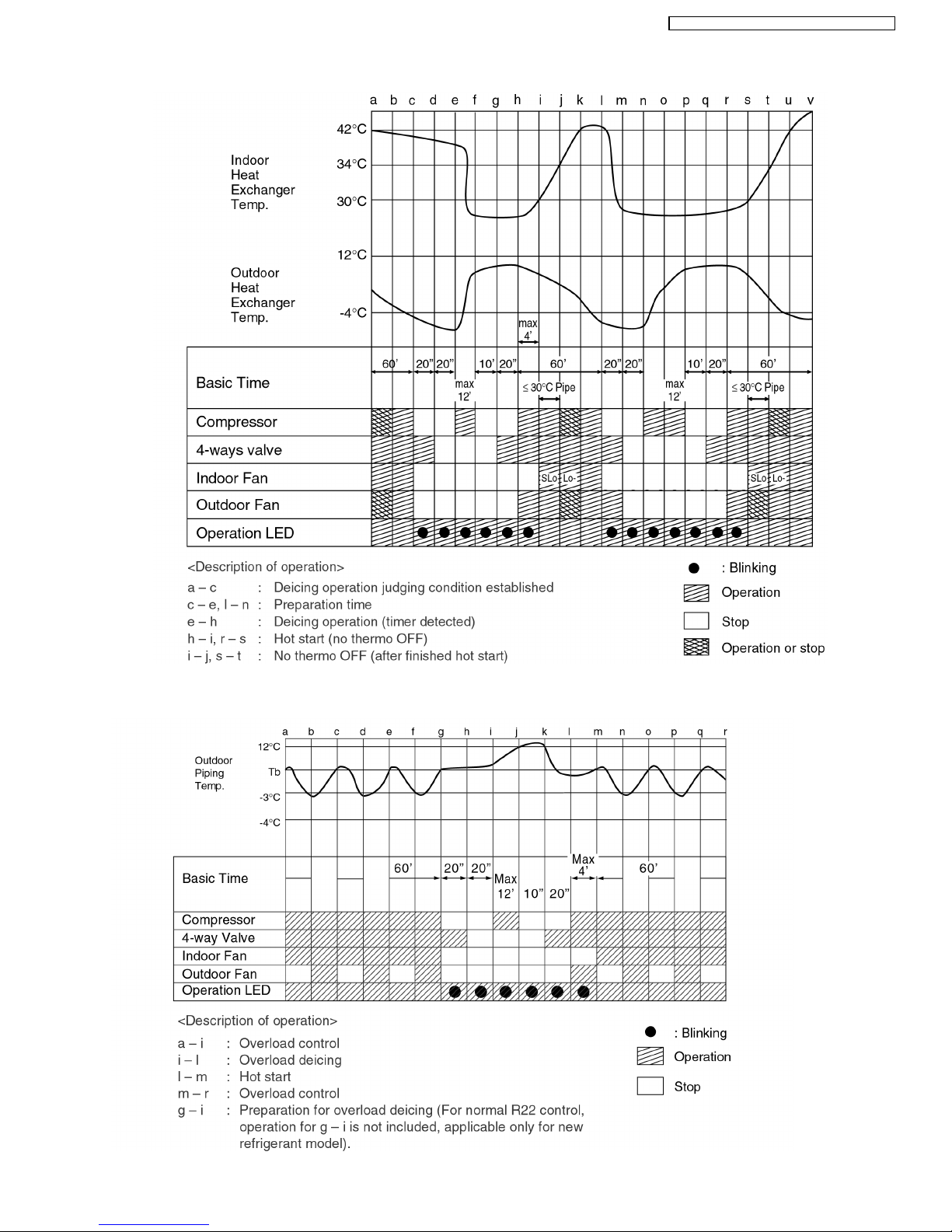
a) Normal Deicing Time Diagram
(b) Overload Deicing Time Diagram
25
CS-W18CK E CU-W 18CKE / CS-W24CK E CU-W24 CKE
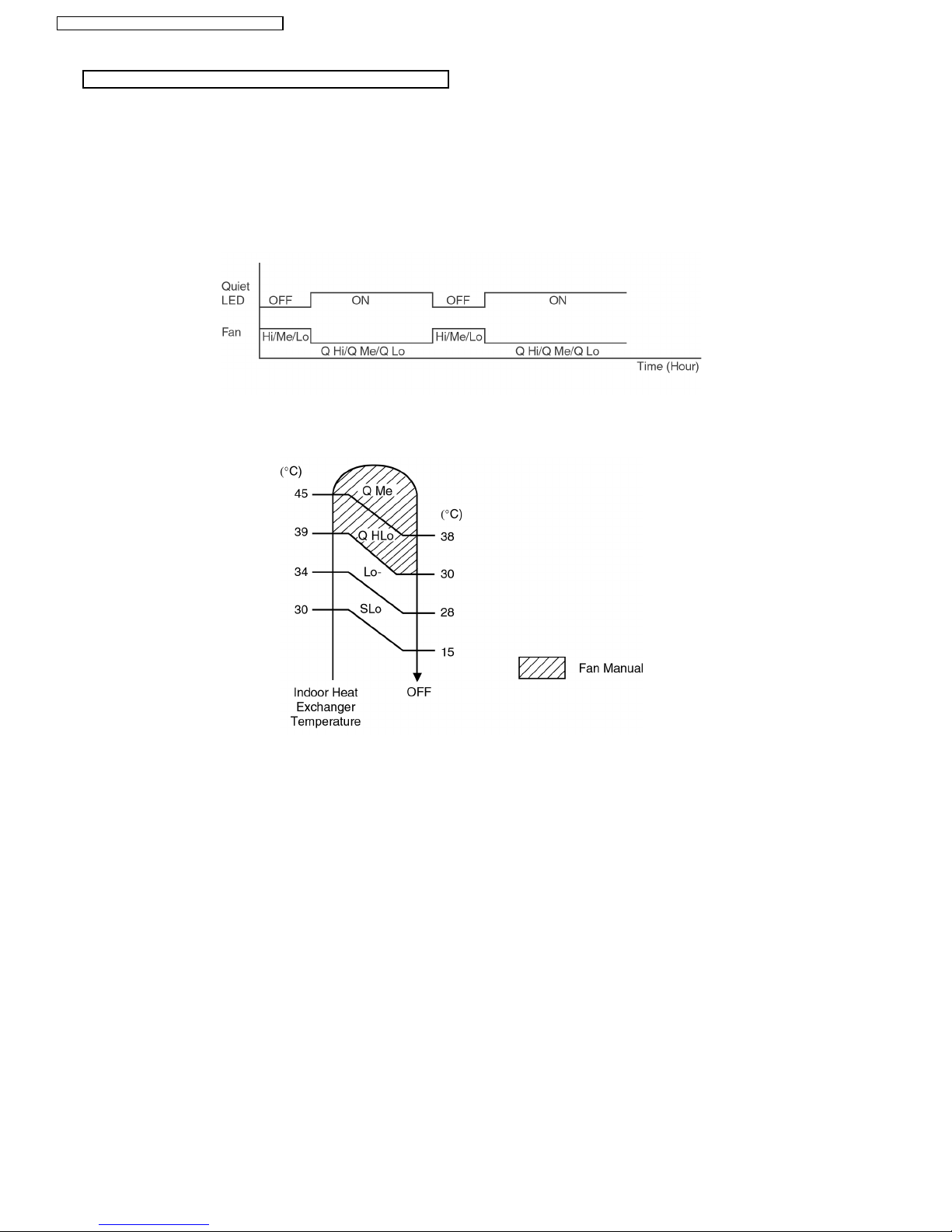
Quiet Operation Control
(For Heating Mode)
•
• •
•
Purpose of this operation is to provide quite heating operation compare to normal operation.
•
• •
•
When the Quiet Mode is set at the remote control, Quiet Mode LED illuminates, the sound level will be automatically
decreased 3 dB, against the present sound level operation.
•
• •
•
Quiet setting of fan speed rpm refer to Indoor Fan Speed Control.
•
• •
•
Manual Fan Speed:-
−
− −
−
Rpm control during Lo, Me & Hi Cool
•
• •
•
Auto Fan Speed:-
−
− −
−
Rpm control depends on the piping air temperature sensor of Indoor heat exchan ger
•
• •
•
Quiet Mode Operation will stop if:-
−
− −
−
Quiet mode button is pressed again.
−
− −
−
Stopped by ON/OFF switch.
−
− −
−
Timer OFF activates.
−
− −
−
Powerful mode button is pressed.
26
CS-W18CK E CU-W 18CKE / CS-W24CK E CU-W2 4CKE
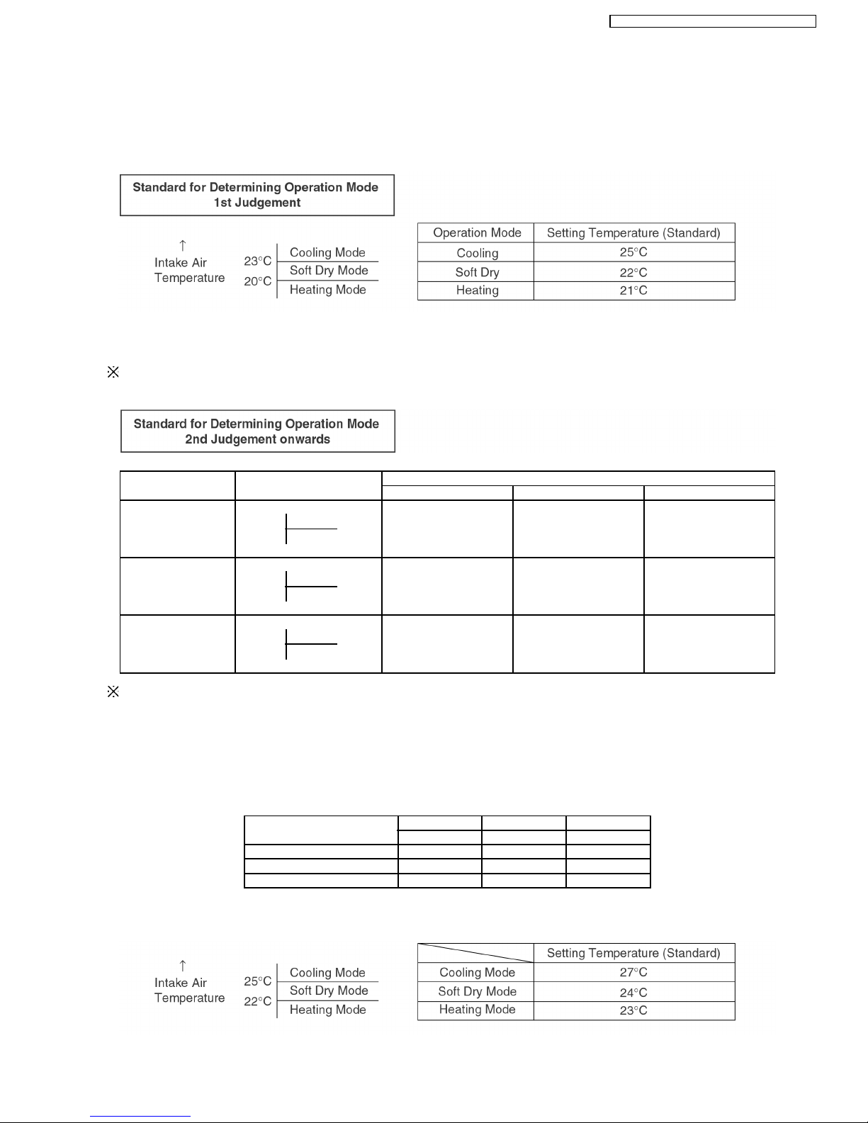
8.5. Automatic Mode Operation
1. When the Automatic Mode Operation is selected, the indoor fan operates at SLo fan speed for 25 seconds to sense intake air
temperature and determine the 1st operation mode. If indoor intake air temperature is less than 16°C, Heating mode will
immediate operate.
2. Operation mode will be determine again after 1 hour of operation, if the room temperature reaches to set temperature and
compressor off time is over 7 minutes 30 seconds continuously.
The present operation mode will be continued, if the room temperature does not reach to set temperature (Compressor keeps running)
eventhough after 1 hour from automatic operation mode started.
Present Judgement Next Mode
Mode Cooling Soft Dry Heating
O O
Cooling 23°C Cooling (Judgement: Not Applicable (Judgement:
Heating 23°C & Above) Below 23°C)
O O
Soft Dry 20°C Soft Dry Not Applicable (Judgement: (Judgement:
Heating 20°C & Above) Below 20°C)
O O
Heating Cooling (Judgement: Not Applicable (Judgement:
25°C Heating Above 25°C) 25°C & below)
Automatic Set Temperature
Refer 3. as below.
3. Automatic Set Temperature
For each operation, set temperature will automatically set as shown below.
However it can be selected 2°C higher or 2°C lower from standard set temperature by pressing the “Room Temperature Setting
button”.
Operation Hi (Standard) Lo
(+2°C) (±0°C) (-2°C)
Cooling 27°C 25°C 23°C
Soft Dry 24°C 22°C 20°C
Heating 23°C 21°C 19°C
•
• •
•
The mode judging temperature and standard setting temperature can be increased by 2°C, by open the circuit of JX1 at
indoor electronic controller.
27
CS-W18CK E CU-W 18CKE / CS-W24CK E CU-W24 CKE
 Loading...