

Page 1
STD
MODE TEMP
OFF
CANCEL SET
FANSPEED
Order No. GMAC0504039C3
Air Conditioner
CS/CU-PC12DKD
CS/CU-PA12DKD
OFF/ON
ON
TIMER
AIRSWING
This service information is designed for experienced repair technicians only and is not designed for use by the general public.
It does not contain warnings or cautions to advise non-techical individuals of potential dangers in attempting to service a product.
Products powered by electricity should be serviced or repaired only by experienced professional technicians. Any attempt to service
or repair the product or products dealt with in this service information by anyone else could result in serious injury or death.
CONTENTS
Page Page
WARNING
1 Features 2
2 Functions 3
3 Product Specifications 6
4 Dimensions 10
5 Refrigeration Cycle Diagram 12
6 Block Diagram 13
7 Wiring Diagram 15
8 Operation Details 17
Installation Insruction
9
--------------------------------------------------------
------------------------------------------------------
------------------------------------------
-----------------------------------------------------
-----------------------------------
--------------------------------------------------
-------------------------------------------------
-----------------------------------------------
---------------------------------------------------
10 2-way,3-way Valve
11
Disassembly of The Parts
12 Troubleshooting Guide
13 Technical Data
14 Exploded View
15 Replacement Parts List
16 Exploded View
17 Replacement Parts List
18 Electronic Circuit Diagram
31
-----------------------------------------------------
--------------------------------------
----------------------------------------
--------------------------------------------------
--------------------------------------------------
-----------------------------------------
--------------------------------------------------
-----------------------------------------
--------------------------------------
41
48
51
53
55
56
57
58
59
C
R
R
Guangzhou Matsushita Air Conditioner Co., Ltd.
(GMAC) All rights reserved. Unauthorized copying
and distribution is violation of law.
Page 2

CS-PC12DKD / CU-PC12DKD / CS-PA12DKD / CU-PA12DKD
1 Features
High Efficiency
Air Quality Indicator
Auto Restart Control
Automatically restart after power failure
Comfort Environment
Air filter with function to reduce dust and smoke
12-hour Timer Setting
2
Page 3
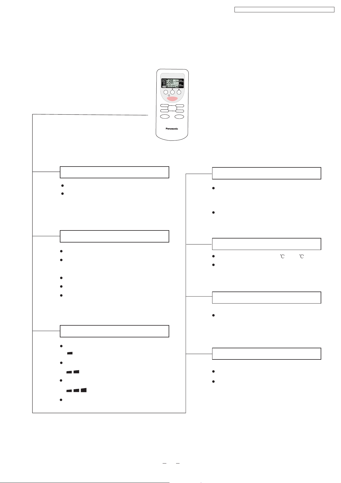
2 Functions
Remote Control
MODE TEMP
OFF
CANCEL
FANSPEED
OFF/ON
TIMER
CS-PC12DKD / CU-PC12DKD / CS-PA12DKD / CU-PA12DKD
STD
ON
SET
AIR SWING
OFF/ON
MODE
FAN
SPEED
Operation START/STOP
Turn on/off the air conditionor
When stop the operation by pressing
OFF/ON button,the cursor key points
to OFF.
Operation Mode Selection
Automatic Operation
Heating Mode Operation
(For PA12DKD)
Cooling Mode Operation
Soft Dry Mode Operation
Air Circulation Mode Operation
(For PC12DKD)
Mode
Indoor Fan Speed Selection
Low Speed
Medium Speed
High Speed
Automatic Speed
AIR
SWING
Airflow Direction Control
Horizontal Airflow Direction Control
-Auto Control
-Manual Control
Vertical Airflow Direction Manual Control
TEMP
Room Temperature Setting
Temperature Setting(16 to 30 )
Auto Operation
TIMER
OFF/ON
Timer Operation Selection
Stop/Start Operation Control
(set the ON/OFF Timer hourly later)
TIMER
SET/
CANCEL
Set /Cancel Timer Operation
Set timer/Cancel the set timer
By pressing SET button for 5seconds
continuously to switch to set the sensor
sensitivity.
3
Page 4
CS-PC12DKD / CU-PC12DKD / CS-PA12DKD / CU-PA12DKD
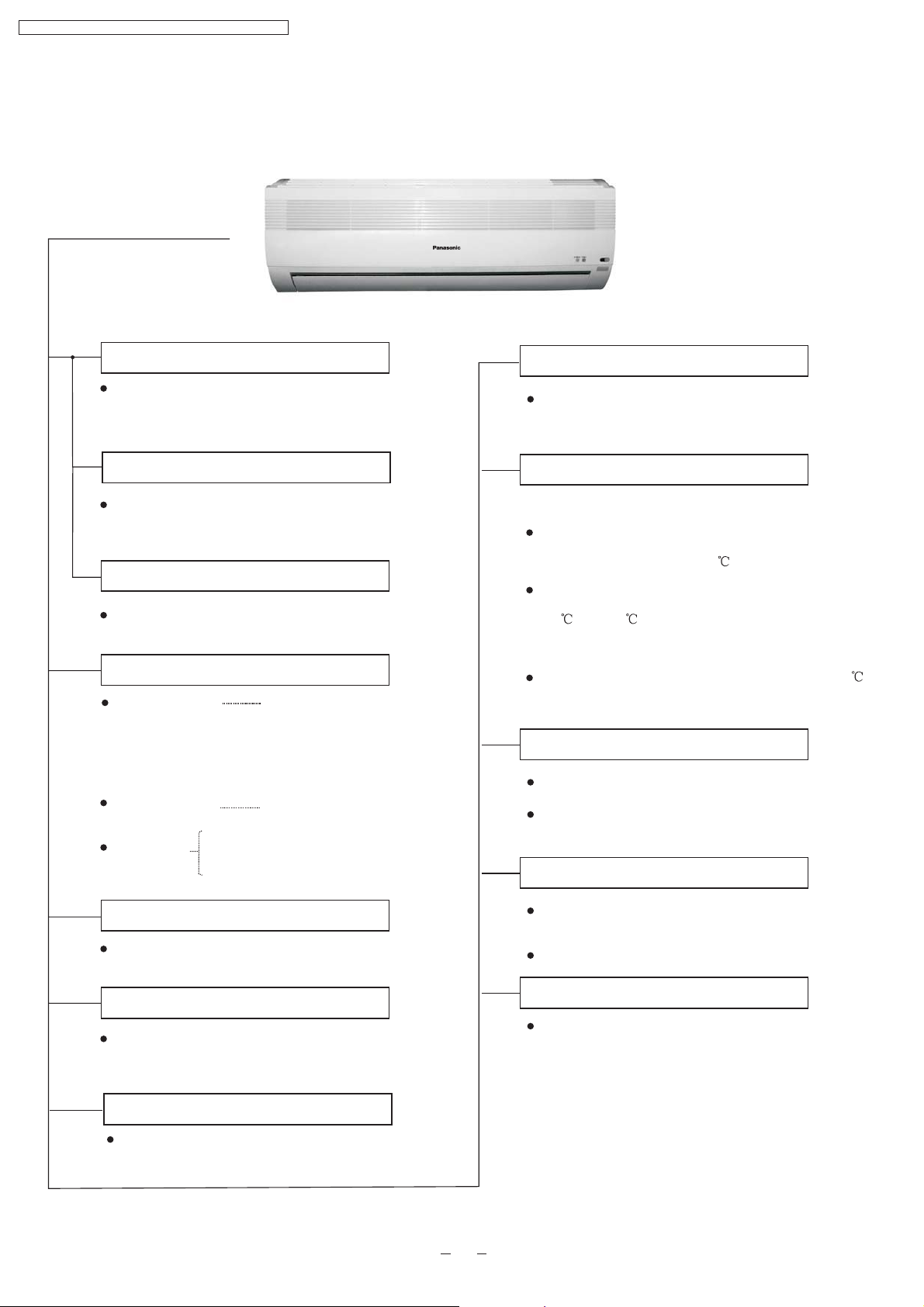
Indoor Unit
Auto Switch
Button
Power Switch ON/OFF
National
Anti-freezing Control for the Evaporator
When the remote control cannot be used or
for repairing and testing ,please use this
button.
Demonstration Mode
Keep pressing this button for 15seconds to start
or end the Demonstration Mode.
Signal Receiving Sound Control
Keep pressing this button for 10seconds to turn
on or turn off the signal receiving sound.
Operation Indication Lamps
Power (green)
Timer(orange)
Air quality
Green
Orange
Red
Lights up in operation;
Blinks during Test
Run operation and
determining Auto
Operation mode
Timer in operation
Cooling or Soft Dry Operation
Warm Booting Control
(For PA12DKD only)
Indoor fan starts running when temperature
of evaporator reaches 30 or above.
When temperature of evaporator is between
30 and 34 ,indoor fan will run at Super Low
or Low speed.
When temperature of evaporator reaches 34 ,
Warm Booting Operation ends.
Indoor Fan Speed Control
High,Med,Low
Auto Fan Speed
Airflow Direction Control
Operation Mode
Cooling/Heating/Soft Dry /Auto Operation
/ Air circulation
Time Delay Safety Control
The unit will restart operation in 3-4
minutes after each pause.
7-Minutes Time Save Control
7-minutes automatic restarting at Cooling
Operation
Automatic Airflow Direction Control
The louver automatically swings up and down
Airflow Direction Manual Control
Delayed On-timer Control
For cooling or soft dry mode, the unit
starts 15 minutes before the set time with
the remote control, but for heating mode
30 minutes before the set time.
4
Page 5
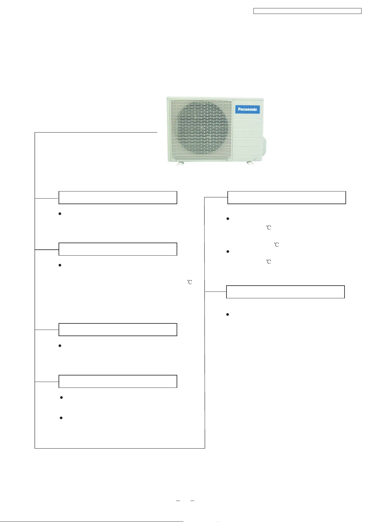
Outdoor Unit
CS-PC12DKD / CU-PC12DKD / CS-PA12DKD / CU-PA12DKD
Panasonic
Anti-reverse Protection
To protect the compressor from reverse
rotation when power off suddenly.
Overload Protector
The 2-step Overload Protector is to protect
the compressor when
1)Temperature of compressor reaches
2)High temperature or current enters into the
compressor
145
60-seconds Test Operation Control
Once the compressor is activated, it does not
stop for 60 seconds. It stops immediately with
remote control ON/OFF button.
Overload Protection Control
(For PA12DKD only)
When the temperature of evaporator
reaches 51 ,outdoor fan stops,and will
restart when the temperature of evaporator
declines to 49 .
When the temperature of evaporator
reaches 65 ,compressor will stop.
4-way Valve Control
(For PA12DKDonly)
If the unit is stopped during Heating
Operation,the 4-way valve will remain in
heating mode operation for 5 minutes.
Deicing Control
Anti-freezing operation for outdoor unit(during
Heating Mode Operation only)
Temperature of the condenser is tested by TRS.
(For PA12DKD only)
5
Page 6
CS-PC12DKD / CU-PC12DKD / CS-PA12DKD / CU-PA12DKD
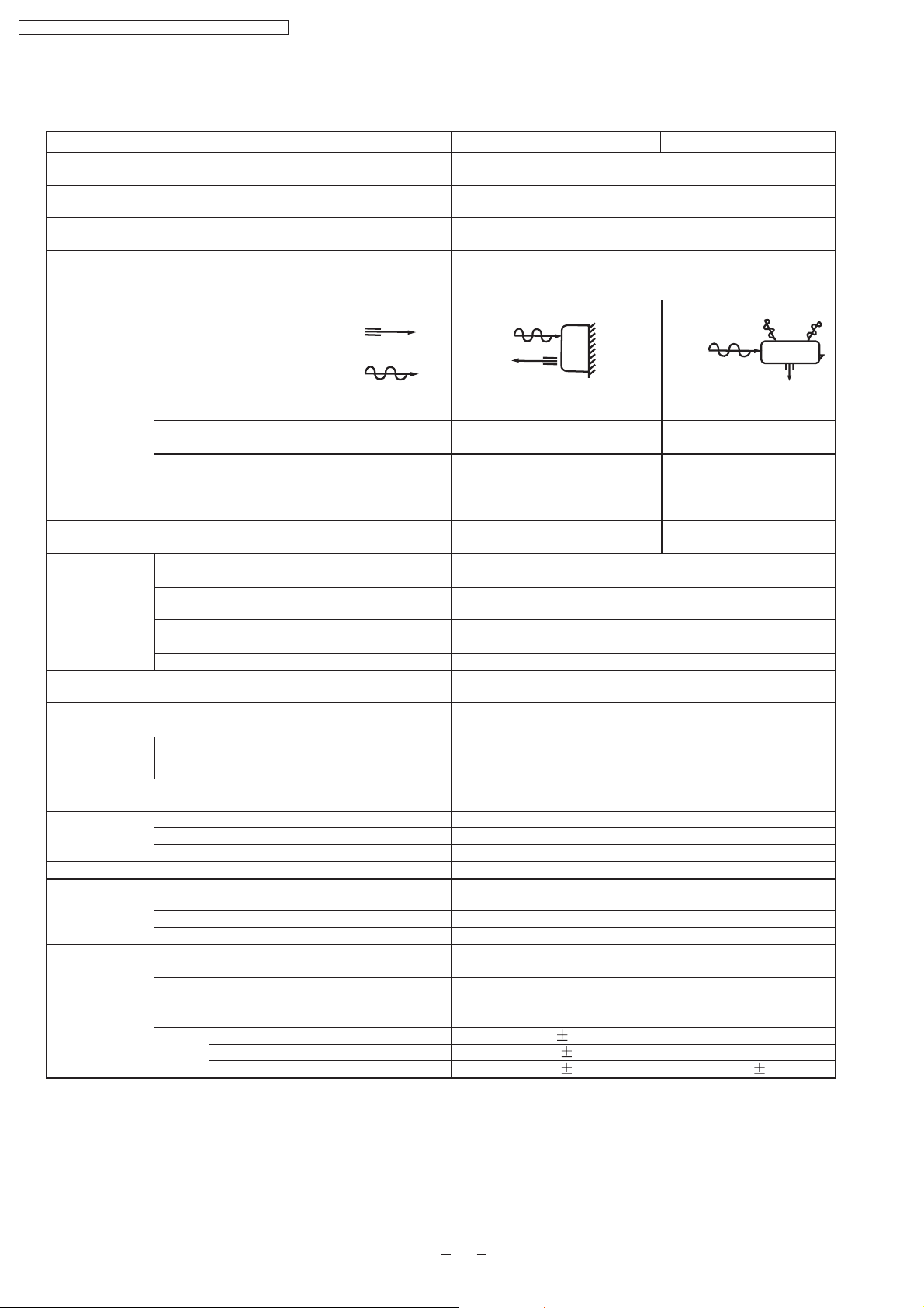
3 Product Specifications
Cooling Capacity
Heating Capacity
Moisture Removal
Power Source
Airflow Method
Air Circulation
Indoor Air (low)
Indoor Air (medium)
Indoor Air (high)
Outdoor Air
Noise Level
Electrical
Input
Data
Running Current
EER/COP
Starting Current
Piping Connection Port(Flare piping)
Piping Size(Flare piping)
Drain Hose
Inner Diameter
Length
Power Supply Cord Length
(Number of core-wire)
Dimensions
Height
Width
Depth
Net Weight
Compressor
Type
Motor Type
Rated output
Air Circulation
type
Motor type
Input
Rated Output
Fan
Speed
Low
Med
High
Unit
kW
kW
L/h
Phase
V
Cycle
OUTLET
INTAKE
3
m /min
3
m /min
3
m /min
3
m /min
dB(A)
W
A
W/W
A
Inch
Inch
Inch
Inch
mm
m
m
mm
mm
mm
kg
W
W
W
rpm
rpm
rpm
CS-PA12DKD CU-PA12DKD
3.35-3.40
3.80-3.85
1.80
Single
220/230
50
SIDE VIEW
7.62
8.48
9.8
-
Cooling:high39,Low32
Heating:high39,Low31
TOP VIEW
-
-
-
-
Cooling:high48
Heating:high49
Cooling:1020-1050
Heating:1000-1030
Cooling:4.80-4.80
Heating:4.80-4.80
Cooling:3.28-3.24
Heating:3.80-3.74
22
G:half union1/2"
L:half union1/4"
G:gas side1/2"
L:liquid side1/4"
14
0.65
1.3
3 core-wire/1.0mm
280
799
183
9
-
-
-
-
-
-
Cross-flow fan
Induction(4 pole)
-
18
980 60
1090 60
1260 60
2
G:3-way valve1/2"
L:2-way valve1/4"
G:gas side1/2"
L:liquid side1/4"
-
-
-
540
780
289
34
Rotary(1 cylinder)
Rolling piston type
Induction(2 pole)
900
Propeller fan
Induction(6 pole)
-
25
-
-
760 50
6
Page 7
Heat
Exchanger
Description
Tube Material
Fin Type
CS-PC12DKD / CU-PC12DKD / CS-PA12DKD / CU-PA12DKD
Unit CS-PA12DKD CU-PA12DKD
Evaporator
Copper
Slot type
Condenser
Copper
Corrugation type
Rows/Stage
(Plate fin configuration,forced draft)
2x15
FPI
Dimensions
Refrigerant Control Device
Refrigeration Oil
Refrigerant (R-22)
Thermostat
Protection Device
Length
Capillary
Circulation
Inner Diameter
Air Filter
mm
(c.c)
g
Electronic Control
mm
L/min
mm
P.P. Honeycomb
21
610x252x25.4
-
-
-
-
-
-
-
Refrigerant Circulation Control Device
Compressor Capacitor
Fan Motor Capacitor
F,V
F,V
-
1.5
* 60g for air purging is not included.
Specifications are subject to change without notice for further improvement.
2X24
21
735.8
X504x36.38
715.1
Capillary Tube
SUNISO 4GDID or ATMOS
M60 or ATMOS 56M
1060(*)
-
O.L.P.(230V,37A)
545 10
12.5 0.2
609 10
10.0 0.2
1.5
Capillary
F,30 370V
F,1.8 400VF , 400V
1.5
7
Page 8

CS-PC12DKD / CU-PC12DKD / CS-PA12DKD / CU-PA12DKD
Cooling Capacity
Moisture Removal
Power Source
Airflow Method
Air Circulation
Indoor Air (low)
Indoor Air (medium)
Indoor Air (high)
Outdoor Air
Noise Level
Electrical
Input
Data
Running Current
Unit
kW
L/h
Phase
V
Cycle
OUTLET
INTAKE
3
m /min
3
m /min
3
m /min
3
m /min
dB(A)
W
A
CS-PC12DKD CU-PC12DKD
3.50-3.55
1.80
Single
220/230
50
SIDE VIEW
7.65
8.26
9.7
-
High39,Low32
TOP VIEW
-
-
-
-
High48
1020-1050
4.80-4.80
EER
Starting Current
Piping Connection Port(Flare piping)
Piping Size(Flare piping)
Drain Hose
Inner Diameter
Length
Power Supply Cord Length
(Number of core-wire)
Dimensions
Height
Width
Depth
Net Weight
Compressor
Type
Motor Type
Rated Output
Air Circulation
Type
Motor Type
Input
Rated Output
Fan
Speed
Low
Med
High
W/W
A
Inch
inch
Inch
inch
mm
m
m
mm
mm
mm
kg
W
W
W
rpm
rpm
rpm
G:half union1/2"
L:half union1/4"
G:gas side1/2"
L:liquid side1/4"
14
0.5
1.3
3 core-wire/1.0mm
280
799
183
9
-
-
-
-
-
-
Cross-flow fan
Induction(4 pole)
-
18
1010 60
1090 60
1280 60
3.43-3.38
23
2
G:3-way valve1/2"
L:2-way valve1/4"
G:gas side1/2"
L:liquid side1/4"
-
-
-
540
780
289
32
Rotary(1 cylinder)
Rolling piston type
Induction(2 pole)
900
Propeller fan
Induction(6pole)
-
25
-
-
760 60
8
Page 9
Heat
Exchanger
Description
Tube Material
Fin Type
Rows/Stage
FPI
Dimensions
Refrigerant Control Device
Refrigeration Oil
Refrigerant (R-22)
Thermostat
Protection Device
Length
Capillary
Circulation
Inner Diameter
CS-PC12DKD / CU-PC12DKD / CS-PA12DKD / CU-PA12DKD
Unit CS-PC12DKD CU-PC12DKD
Evaporator
copper
slot type
Condenser
copper
Corrugation type
(Plate fin configuration,forced draft)
2x15 2x24
mm
(c.c)
g
21
610x252x25.4
-
-
-
Electronic Control
Capillary Tube
SUNISO 4GDID or
ATMOS M60(M56)
O.L.P.(37A/230V)
21
735.8x504x25.4
760(*)
mm
L/min
mm
-
-
-
350 10
15.0 0.2
1.5
Air Filter
P.P Honeycomb
Refrigerant Circulation Control Device
Compressor Capacitor
Fan Motor Capacitor
F, V
F, V
-
* 60g for air purging is not included.
Specifications are subject to change without notice for further improvement.
Capillary
30
F,
F,1.8 440VF,1.5 400V
-
370V
9
Page 10

CS-PC12DKD / CU-PC12DKD / CS-PA12DKD / CU-PA12DKD
4 Dimensions
Indoor Unit
Unit : mm
Side view
Left Piping
Hole
Air intake
Air outlet
Front View
280
<Back View>
790
Installation Plate Hook
61
Gas Side
165
Liquid
Side
49
183
49
MODE
OFF
CANCEL
FANSPEED
TIMER
STD
TEMP
OFF/ON
ON
SET
AIRSWING
Right Piping
Hole
61
5
125
(100)
(420)
Drain Port
Installation plate (Front View)
254
95
(131)
B
(50)
56
16.5
A
(382) (118)
(631)
10
Page 11
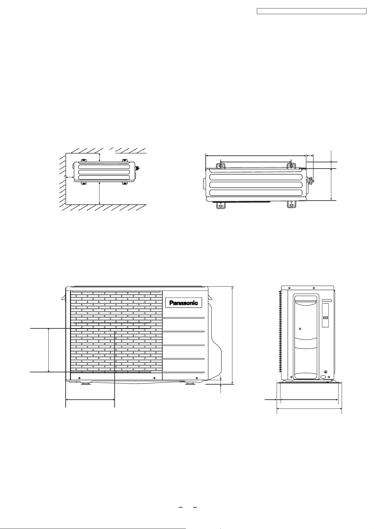
Outdoor Unit
CS-PC12DKD / CU-PC12DKD / CS-PA12DKD / CU-PA12DKD
Unit : mm
<Top View>
More
than 10cm
More
than 10cm
More than 100 cm
<Front View>
INVERTER
780
570
48
34.5
289
<Side View>
291
274
11
18
540
16
320
352
Page 12

INTAKE AIR
SENSOR
PIPING
SENSOR
PIPING
SENSOR
CS-PC12DKD / CU-PC12DKD / CS-PA12DKD / CU-PA12DKD
5 Refrigeration Cycle Diagram
CS/CU-PA12DKD
AIR QUALITY
SENSOR
INTAKE AIR
SENSOR
PIPING
SENSOR
PIPING
SENSOR
4-way valve
Cooling
Heating
CS/CU-PC12DKD
INTAKE AIR
AIR QUALITY
SENSOR
SENSOR
PIPING
SENSOR
PIPING
SENSOR
12
Page 13
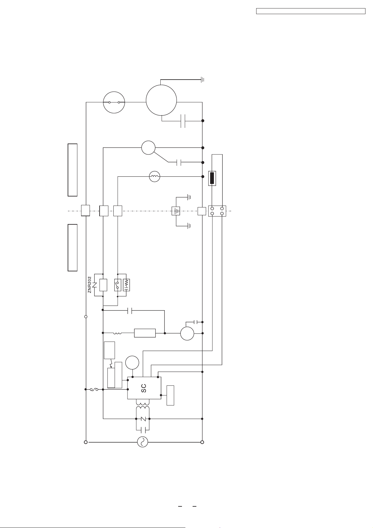
6 Block Diagram
CS-PA12DKD/CU-PA12DKD
O.L.P.
Compressor
FM
CS-PC12DKD / CU-PC12DKD / CS-PA12DKD / CU-PA12DKD
OUTDOOR UNIT
INDOOR UNIT
4-Valve
4
SSR202
RY-HOT
Remote
Control
3
CR201
SSR201
FM
1
RY-PWR
Piping Sensor
2
FM
FUSE
Receiver
Indicator
POWER SUPPLY
Sensor
AC220V-230V 50Hz
13
Page 14
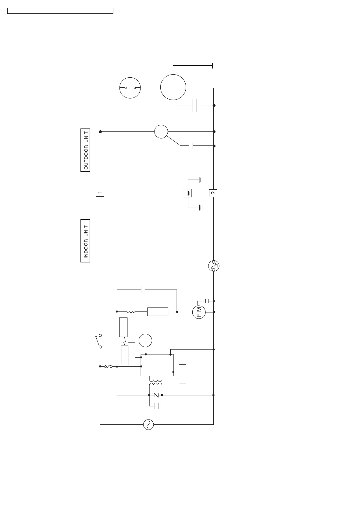
CS-PC12DKD / CU-PC12DKD / CS-PA12DKD / CU-PA12DKD
CS-PC127DKD/CU-PC12DKD
O.L.P.
Compressor
FM
RY-PWR
FUSE
Remote
Control
Receiver
FM
Indicator
POWER SUPPLY
AC220V-230V 50Hz
SSR201
SC
Sensor
14
Page 15
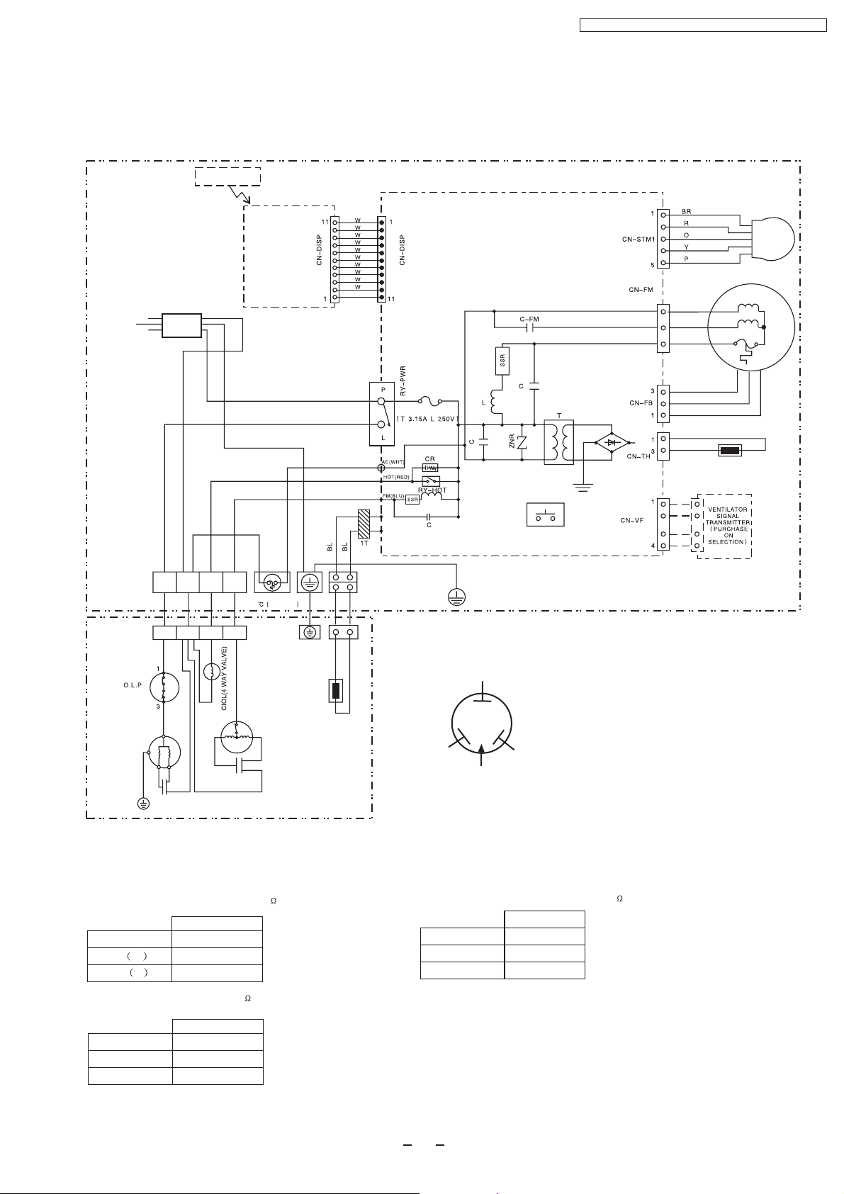
7 Wiring Diagram
POWER SUPPLY
CORD
AC 220V/230V, 50Hz
CS-PA12DKD/CU-PA12DKD
Wireless
Remote Control
CS-PC12DKD / CU-PC12DKD / CS-PA12DKD / CU-PA12DKD
AC 220V/230V, 50Hz
INDOOR UNIT
TERMINAL BOARD
POWER SUPPLY
CORD
B
1(L) 2(N) 3 4
Indicator
Complete
BR
BL
Y/G
FUSE
102 250V 3A
ELECTRONIC CONTROLLER
STEPPING
MOTOR
1
B
3
R
5
Y
W
FUSE
W
R
B
AUTO SWITCH
Y/G
BR
BL
SENSOR(PIPING TEMP.)
FAN MOTOR
INDOOR UNIT
OUTDOOR UNIT
TERMINAL BOARD
COMPRESSOR
1(L) 2(N) 3 4
YW
Y
Y/G
R
CAPACITOR
Y
FAN MOTOR
R
B
B
CAPACITOR
B
OUTDOOR UNIT
INDOOR FAN MOTOR RESISTANCE( )
CS-PA12DKD
CONNECTING
Y-B M
Y-R A
COMPRESSOR RESISTANCE( )
CWA921098
324
290.5
CU-PA21DKD
CONNECTING
C-R
C-S
CWB092281
2.803
4.420
R : RED
BL : BLACK
YELLOW
C
B : BLUE
BR : BROWN
O : ORANGE
SENSOR(PIPING TEMP.)
R
BLUE
TRADE MARK
S
RED
COMPRESSOR TERMINAL
OUTDOOR FAN MOTOR RESISTANCE( )
GRY : GREY
G : GREEN
Y : YELLOW
W : WHITE
Y/G : YELLOW/GREEN
P : PINK
CU-PA21DKD
CONNECTING
Y-B
Y-R
CWA951440
272
248
15
Page 16

CS-PC12DKD / CU-PC12DKD / CS-PA12DKD / CU-PA12DKD
POWER SUPPLY
CORD
AC 220V/230V 50Hz
CS-PC12DKD/CU-PC12DKD
Wireless
Remote Control
POWER SUPPLY
CORD
AC 220V/230V 50Hz
B
Indicator
Complete
Y/G
THERMAL FUSE
102 (250V 3A)
W
W
W
W
W
W
W
W
W
W
W
W
ELECTRONIC CONTROLLER
AC(WHT)
AUTO SWITCH
BR
R
O
Y
P
B
R
Y
W
BR
BL
SENSOR(PIPING TEMP.)
STEPPING
FAN MOTOR
MOTOR
Y/G
VENTILATION SIGNAL
TRANSMITTER(PURCHASE
ON SELECTION)
INDOOR UNIT
Y
Y
FAN
MOTOR
R
B
CAPACOTOR
B
B
CAPACOTOR
Y
R
INDOOR FAN MOTOR RESISTANCE( )
CS-PC12DKD
CONNECTING
Y-B M
Y-R A
COMPRESSOR RESISTANCE( )
CWA921098
324
290.5
CU-PC21DKD
CONNECTING
C-R
C-S
CWB092281
2.803
4.420
O.L.P
COMPRESSOR
Y/G
OUTDOOR
UNIT
YELLOW
C
R
BLUE
TRADE MARK
S
RED
COMPRESSOR TERMINAL
OUTDOOR FAN MOTOR RESISTANCE( )
CU-PC21DKD
CONNECTING
Y-B
Y-R
CWA951423
272
248
R : RED
BL : BLACK
B : BLUE
BR : BROWN
O : ORANGE
GRY : GREY
G : GREEN
Y : YELLOW
W : WHITE
Y/G : YELLOW/GREEN
P : PINK
16
Page 17
CS-PC12DKD / CU-PC12DKD / CS-PA12DKD / CU-PA12DKD
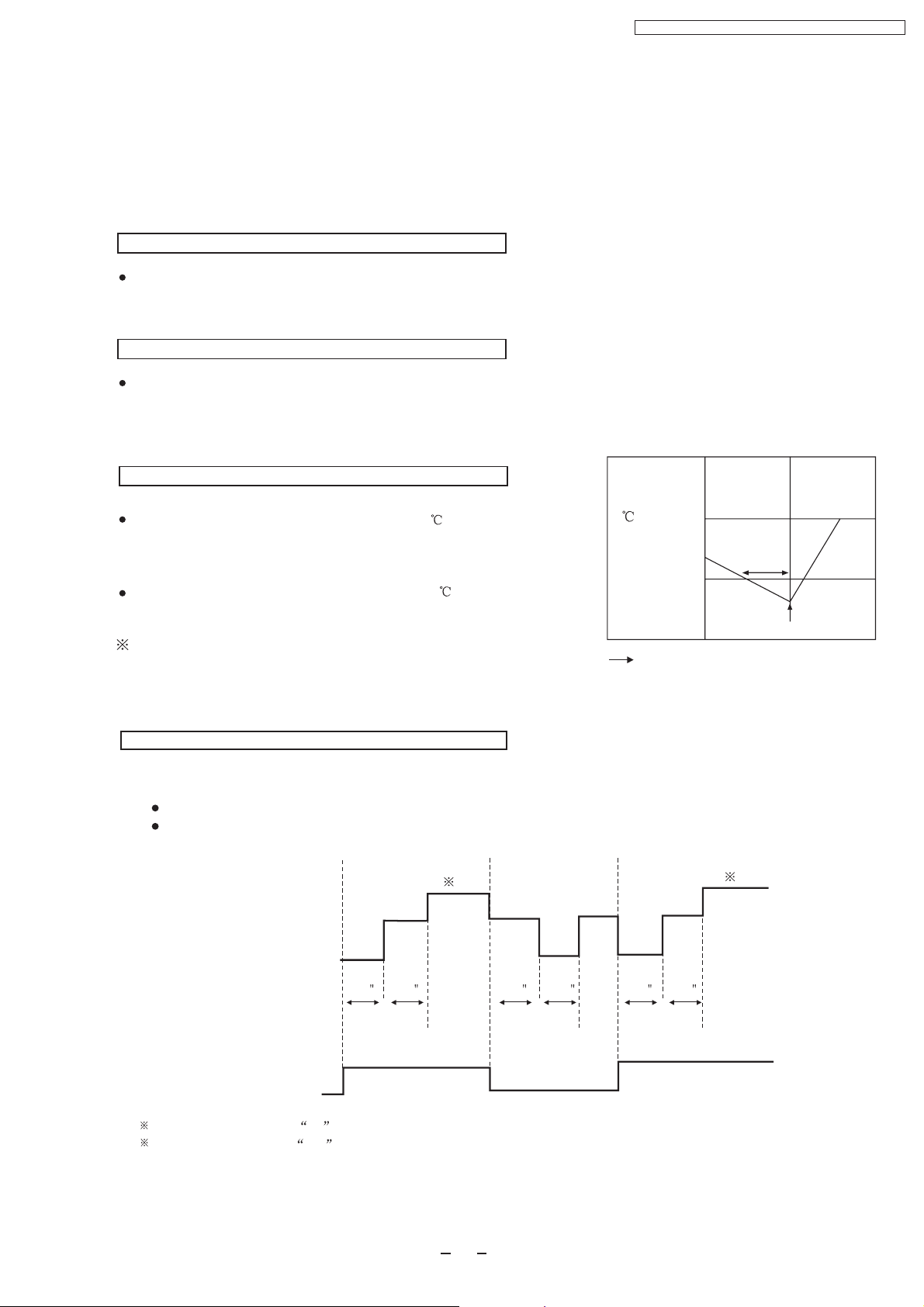
8 Operation Details
8.1 .Cooling Mode Operation
When selecting the Cooling Mode Operation, the unit will operate according to the setting by the Remote Controller or
the control panel on the indoor unit and the operation is as the following.
Time Delay Safety Control
3 min.----If the compressor stops, it will not restart within 3 minutes.(Protection of compressor).
7 Minutes Time Save Control
7 min.----The unit will automatically operate in 7 minutes even if the room temperature is not reached.
(Prevention of raising the humidity)
Anti-Freezing Control
If temperature of evaporator is lower than 2 continuously
Evaporator
Temperature
()
for 4 minutes, the compressor will cease to prevent the
evaporator from freezing. Fan speed setting will not be
changed.
When temperature of evaporator reaches 10 ,compressor
will restart.
During Cooling Mode Operation, the Time Delay Safety
Control is available.
Time
Automatic Fan Speed Mode
During Cooling Mode Operation, use remote controller to select Automatic Fan Speed.
Fan speed will be at the point between "High speed" and "Medium speed".
Deodorization control.
1
Indoor Fan
STOP
Slow
Slow
STOP STOP
Slow Slow
10
4 minutes
2
Compressor ceases
2
Restart
40 30 40 3020 160
Compressor
ON
STOP
1 Fan speed will be at Hi till the compressor ceases (set temperature reached).
2 Fan speed will be at Me when the compressor restarts.
17
ON
Page 18
CS-PC12DKD / CU-PC12DKD / CS-PA12DKD / CU-PA12DKD
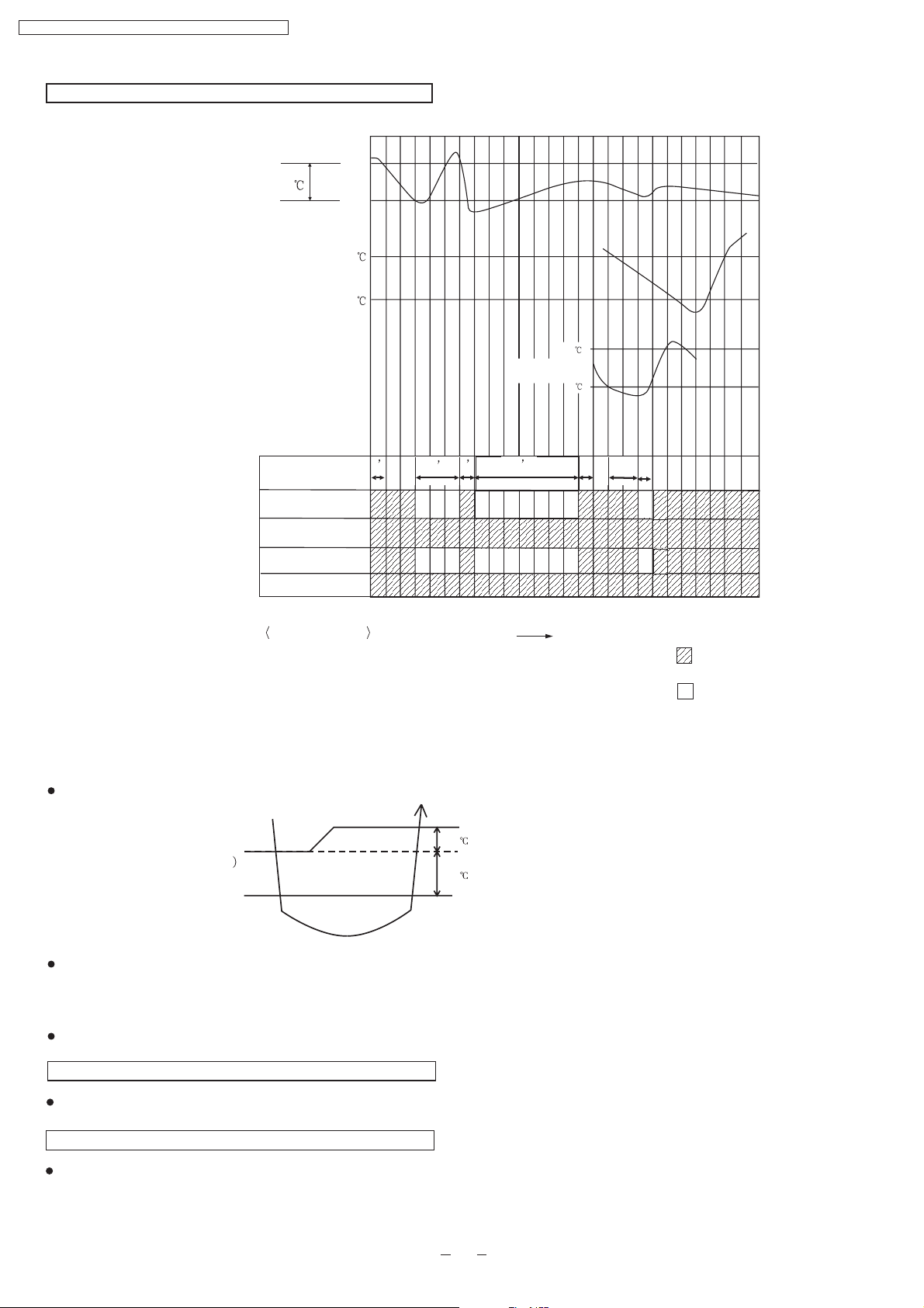
Time Graph for Cooling Operation
Intake air temperature
Set temperature
1.5
Basic Time
Comp.
Indoor Fan
Outdoor Fan
abcdefghi j k lmnopqrstuvwxyz
Start
Stop
31
29
10
2
1’
3
4’
1 1
3
Evaporater
temperature
7
Operation Indicator
Operation status
d-g
g-h
h-o
q-t
:
Time delay safety control
:
Compressor Test control
:
Auto restart control
:
Anti-freezing Control
Time
Operate
Stop
8.2. Soft Dry Mode Operation
Operation area
COOLING
COOLING(OFF)
DRY(ON
DRY
DRY(OFF)
DRY(OFF)
When selecting Soft Dry mode operation, the operation will be cooling until the room temperature reaches the set temp on
remote control, and then Soft Dry will be activated. (During Soft Dry Mode the fan of indoor unit will operate at super low
speed. The soft dry mode will run for less than 10 minutes.)
Once Soft Dry mode operation is turned off, indoor fan, compressor and outdoor fan will stop for 6 minutes.
COOLING(ON)
1.5
1.0
DRY(ON)
Time Delay Safety Protection
During cooling mode operation, if the compressor ceased, it will not restart within 3 minutes.
Anti Freezing Control
Same as the denotation in Cooling Operation.( )
P21
(During Soft Dry Mode Operation, compressor will stop for at least 6 min.)
18
Page 19

Automatic Fan Speed
During Soft Dry Operation, use remote controller to select Auto Fan Speed mode.
Indoor Fan Speed is at “Lo-”
CS-PC12DKD / CU-PC12DKD / CS-PA12DKD / CU-PA12DKD
Lo-
Slo
Indoor
fan
OFF
T1
40
T2
70
10
Compressor
ON
Time Graph for soft dry operation
Intake Air temp
Cooling mode operation activated
1.5
1.0
Cooling mode operation stopped
Soft mode operation activated
Soft dry mode operation stop
Lo-
Slo Slo
OFF OFF OFF
T1
40
6
T2
70
10
ON
OFF
abcdef g hi jklmnopq rst u
Basic Time
Comp.
Indoor Fan
Outdoor Fan
Operation Indicator
4-way Valve
Operation status
a-c,p-r
c-p,r-u
e-f
j-l
q-t
:
Cooling Mode Operation
Soft Dry Mode Operation
:
:
Soft Dry Mode Operation Stopped
Compressor Test Operation Control
:
:
Anti Freezing Control
Evaporator
temperature
61 1 4
1
Super
Super
Super
Slo Slo Slo Slo
Low
Low
Low
Super
Low
Low
Slo Slo
Slo Slo Slo
Time
o
10 C
o
2C
666
Slo
Slo
Cooling mode operation
Soft Dry Mode operation
Operate
Stop
19
Page 20

Super Low
Indoor Fan
Stop
Indoor Heat
Exchanger
()
CS-PC12DKD / CU-PC12DKD / CS-PA12DKD / CU-PA12DKD
8.3. Heating Mode Operation(Only for PA12DKD)
When selecting the Heating Mode Operation, the unit will operate according to the setting by the Remote Controller and
the operation is as the following.
Time Delay Safety Control
If the compressor stopped by switching off, turning off by remote controller, or power off, it will not restart within 3 minutes.
When room temperature reaches the set temperature on the remote controller, compressor stops and will not restart within
4 minutes.
3 minutes after the compressor stopped, indoor fan will stop for 1 minute. Then indoor fan will resume operation with the
speed at ”super low”
Over Load protection Control
When temperature of indoor heat exchanger rises to 51 , outdoor fan will stop
when temperature of indoor heat exchanger falls to 49 , outdoor fan will restart.
When temperature of indoor heat exchanger rises to 65 or above, compressor stops, and will restart 4 minutes later.
.
Compressor
Indoor Heat Exchanger 65
Anti-reversing Control
If the compressor has been continuously running for 5 minutes or longer, and the difference of temperature between
intake air and evaporator is continuously lower than 5.0 or below for 2 minutes, the compressor will stop , and then
restart 3 minutes later.(Time Delay Protection Control is effective.)
Compressor runs 5 min
T 5 last for 2 min
T= intake air temperature - evaporator temperature
4-way valve control
During heating mode operation,4-way valve is at open mode.
During heating mode operation,if the unit turned off, the 4-way valve will remain
at open mode for 5 minutes.
Stops
Compressor
Stops
Compressor Restarts
4 minutes later
Compressor Restarts
3 minutes later
Warm Booting Control
When turning on the unit by heating mode operation,indoor fan
will be activated when temperature of indoor heat exchanger
reaches 30 . (See the figure on the right)
Warm boot operation ends when temperature of indoor heat
exchanger reaches 34 .
20
Indoor Heat
Exchanger
()
34
30
Low
Super Low
Indoor Fan
Stop
Page 21

Automatic Fan Speed
S Lo
()
()
45
41
34
30
38
30
28
15
Temperature of heat exchanger
During Heating Operation, use remote controller to select Auto Fan Speed mode.
Indoor Fan Speed is between “Me” and “Slo”.
()
SLo
Me
Lo
Lo-
()
38
30
28
45
41
34
30
CS-PC12DKD / CU-PC12DKD / CS-PA12DKD / CU-PA12DKD
Temperature of heat exchanger
Time Graph for Heating Operation
abcdefghi jk
42
Indoor heat
exchanget
Temp.
Intake Temp.
34
32
30
OFF
2
ON
Basic Time
Compressor
Indoor Fan
Outdoor Fan
Operation Indicator
4-way valve
Stop
30'
58''
15
l
nop qr
m
Manual fan speed
Blink
Operate
Stop
150'
1'
30
<Operation status>
a-b
c-d
h-k,o-r
:
Warm booting control(indoor fan Off)
:
Warm booting control(indoor fan Super Slo)
:
Prevent cool air blowing out
Tim e
21
Page 22

Deicing Operation Time(T)
3
min
3min T 7min
7
min T 9min
T 9min
Td(s)
0
60
120
180
<Operation status>
CS-PC12DKD / CU-PC12DKD / CS-PA12DKD / CU-PA12DKD
Deice Control
Deice operation is to protect the outdoor unit from freezing.
Normal Deice Operation
Deicing starts 30 minutes after heating mode operation or 60 minutes after the latest deicing operation. If temperature of
outdoor piping, tested by TRS, falls to -3 (TRS OFF) or below for continuously 50 seconds, deicing operation starts.
Overload Deicing Operation
During heating operation, if the accumulative stopping time of outdoor fan reaches 60 minutes,
deicing operation will start 1 minute after compressor starts.
Deicing operation ends under conditions below
(a) After 12 minutes.
(b) Temperature of outdoor unit rises to 4 .
(c) As the illustration showed bellow and due to Time Delay (Td), deicing won’t ends immediately.
Deicing Operation Time(T)
3min
3min T 7min
7 min T 9min
T 9min
Td(s)
0
60
120
180
Once deicing operation starts, it won’t end until 60 seconds later.
When deicing operation ends, compressor will stop for 30 seconds, and 4-way valve remains at cooling mode operation
for 10 seconds.
Time Graph for Normal Deicing Operation
Lo
max60'
l
nopq r s t uvwxy z
m
max12'
Slo
or
Blink
Operat io n
Stop
max60'
Lo
42
34
30
Indoor Piping Temp.
Basic Time
Compressor
Indoor Fan
Outdoor Fan
Operation LED
4-way valve
abcd ef gh i j k
60'
max12'
10S20S 20S 20S 20S 20S 10S 20STd
Slo
Time
<Operation status>
a-c Deicing confirmation
c-g Deicing operation(time reset)
h-j,u-w Warm Booting
o-r Deicing(TRS )
22
Page 23

Time Graph for Overload Deicing
Outdoor Heat
Exchanger
CS-PC12DKD / CU-PC12DKD / CS-PA12DKD / CU-PA12DKD
Outdoor Heat
Exchanger
Basic time
Compressor
abcdef ghi j k
51
49
Out door fan stop for 60' accumulatively
20’’ 20’’
Max
12’
l
m
10’’ 20’’
nopq
Indoor fan
Outdoor fan
Operation Indicator
4-way valve
<Operation status>
Overload controla-i
i-l Overload deicing(timer)
l-m: Warm booting control
m-r Overload control
Time
Blin k
Oper ati on
Stop
23
Page 24

CS-PC12DKD / CU-PC12DKD / CS-PA12DKD / CU-PA12DKD
8.4 Automatic Mode Operation
Standard for Determining Operation Mode
First Determination:
Setting Temperature (Standard)
25
22
21
Intake Air
temperature
23
20
Cooling mode
Soft Dry mode
Heating mode
Cooling mode
Soft Dry mode
Heating mode
Second Determination:
One hour after the above determination, the unit will operate according to the table below.
Second Determination
Cooling
Cooling
First
determination
A)
Indoor fan operates at super low speed for 25 seconds.
B)
After judging indoor air temperature, the operation is determined and operation continued at the mode determined.
C)
If indoor temperature is less than 16 , heating operation will immediately operate.
D)
After the operation mode has been determined, the mode does not change. However,Soft Dry mode operation
includes cooling mode operation.
E)
If automatic mode operation is started while the unit is operating,operation will continue.
If current operation is in cooling mode (including the cooling mode operation when is a part of Soft Dry mode
operation) it will be maintained, and if current operation is not cooling mode, the appropriate operation mode is
determined for 25seconds at super slow fan speed.Then the selected mode will continue.
F)
Room temperature adjustment
Dry
Heating
Higher
23 or above
25 or above
2
Dry
20 or above
Heating
23 below
20 below
25 below
Standard
Lower
0
2
8.5. Air Circulation Mode Operation(Only for PC12DKD)
1. An additional heater may make the warm air evenly covering each corner of the room.
2. When the temperature near the ceiling reaches the setting temperature, Air Circulation Mode Operation commences
at low airflow volume. It stops when the temperature drops to 2 below the setting temperature.
3. The vertical airflow direction louver will not swing.
24
Page 25

CS-PC12DKD / CU-PC12DKD / CS-PA12DKD / CU-PA12DKD
8.6 Air Quality Sensor Control
Resistance of air quality sensor: Rs(air)=10k ~50k ( The worse the air quality, the smaller the resistance.)
Basic Operation
Detecting and indicating of the air quality will not stop during the operation of the air conditioner.
The power of the air quality sensor is always on during the operation of the air conditioner. When the air
conditioner stops (The air conditioner is on standby.), the air conditioner will provide power to the air quality
sensor intermittently (It will be on for 3 minutes after each 109 minutes.) for the purpose of air quality detecting.
Within 2 minutes after the air conditioner starts to operate, the air quality sensor is in the process of preheating
and the air quality indicator is red.
Resistance Reference
Detecting of air quality( During the operation of the air conditioner)
(a) The measuring period is 20 minutes; The air conditioner will measure the resistance (Rs) of the air quality
sensor once each 2 seconds and record the data. The maximum Rs within the 20 minutes will be selected as
Rs(MAX) for this measuring period.
(b) Suppose the current Rs(MAX) as MAX and the resistance reference of the previous measuring period is as
MAXR1.; If MAX>MAXR1, the resistance reference of the current measuring period is MAXR=MAX; If
MAX<MAXR1, MAXR=MAXR1;
(c) Within 2 minutes after the power of the air quality sensor is turned on, the resistance reference of this
measuring period is the maximum resistance of the sensor during this period.
Maximum of Rs
MAXR1 of previous
measuring period
Updating of MAXR
20minutes
MAX1 MAX2 MAX3
MAX0 MAX1 MAX2
MAX1 MAX0 MAX0
MAX1 MAX0 MAX1
MAX2 MAX1 MAX1
MAX2 MAX1 MAX2
20minutes20minutes
MAX3 MAX2 MAX2
MAX3 MAX2 MAX3
The following conditions should be fulfilled
(d)
The initial MAXR after the preheating of the air quality sensor when the air conditioner is turned on:
The air conditioner will compare the maximum value of the current measuring period (MAX) with the
resistance reference 109 minutes before ( MAXR0) and select the bigger one as the current resistance
(e)
reference(MAXR).
When the air conditioner determines the air quality is getting worse: Air quality level 1 Air quality level 2,
MAXR will not be updated; When the air quality gets better (air quality level 0), Rs detected at this time will be
(f)
MAX and MAXR.
The air conditioner will not detect the air quality during deicing operation. The indication prior to the deicing
operation will be held during the deicing operation.
25
Page 26

CS-PC12DKD / CU-PC12DKD / CS-PA12DKD / CU-PA12DKD
Detecting of air quality( When the air conditioner is on standby.)
(a) After the air conditioner stops operation, it will provides power to the air quality sensor intermittently to detect
the air quality and update the resistance reference (MAXR). The power of the air quality sensor will be on for 3
minutes after each 109 minutes.
(b)
During these 3 minutes, the air quality sensor will be in preheating process for 2 minutes and the other time is
for measuring the resistance. The air conditioner will compare the maximum resistance measured in this period
with the maximum value in the previous 109 minutes and the bigger one will be selected as resistance
Air Quality Control
Detecting of air quality(When the air conditioner is on standby.)
Rs/MAXR will be calculated automatically every 2 seconds and the air quality level will be determined in
accordance with the value below,
Air Quality
Getting Worse
Air Quality
Getting Better
*G1=0.85
*G2=0.60
Signal of Air Quality Sensor
Air quality
becomes better
Rs/MAXR G1
Rs/MAXR G2
Rs/MAXR G3
Rs/MAXR G4
Air Quality Level
(0) (1)
(2) (1)
(1) (0)
Air quality
(0)
becomes worse
(1)
(2)
(2)(1)
Set the sensitivity number of the air quality sensor as 2 (Standard)
Air Quality Level and Indicator
During preheating of the air quality sensor the air quality indicator is red.
The color of the air quality indicator varies with the air quality level:
Air Pollution Level 0: Green
Air Pollution Level 1:Orange
Air Pollution Level 2:Red
26
Page 27

CS-PC12DKD / CU-PC12DKD / CS-PA12DKD / CU-PA12DKD
Forced Resetting
Forced Resetting Time (The added operation time mentioned later not included.)
(a) Air Pollution Level 2: Red: 5 minutes Orange: 8 minutes Green
(B) Air Pollution Level 1: Red: 5 minutes Orange: 8 minutes Green
Timer Resetting
When the forced resetting mode is determined and the following conditions are fulfilled, the timer is reset.
1) The air quality changes which results in the changing of the color of the air quality indicator.
2) Compare Rs detected in current 2 seconds with R1 detected in previous 2 seconds and Rs/R1<0.95.
3) Suppose Rs detected in previous 3 minutes is R2 and Rs/R2 0.87.
Added Operation of Air Quality Sensor
When the air quality getting worse
If the air pollution level changes from 0 to 2, the color of the air quality indicator changes as below,
Green Orange (2 Sec.) Red
When the air quality getting better (added operation )
If the air pollution level changes from 2 to o, the color of the air quality indicator changes as below,
Red (60 Sec. ) Orange( 60Sec.) Green
Judgment during added operation
During added operation, if the air quality sensor judges that the air quality is getting worse, the added operation will
be stopped immediately and the air quality indicator will shift to normal indication. If the air quality getting better,
the air conditioner will judge the air quality until the added operation is finished.
Sensitivity Control of Air Quality Sensor
The sensitivity number can be changed through the following procedure
<Setting Sensitivity Number>
1.Keep the SET button on the remote control depressed continuously for 5 seconds to select sensitivity control
m ode.
2.The previous sensitivity setting will be displayed in the temperature display.
“0”=Turn off the air quality indicator
“1”= Low Sensitivity
“2”=Standard Sensitivity
“3”=High Sensitivity................
…………....G1=0.70, G2=0.45, G3=0.48, G4=0.73
………G1=0.85, G2=0.60, G3=0.63, G4=0.88
G1=0.90, G2=0.65, G3=0.68, G4=0.93
3.Press or button on the remote control to change the sensitivity
Within 10 seconds after the sensitivity setting is finished, other settings are not available. The display of the remote
control will change back to normal without pressing any button.
27
Page 28

CS-PC12DKD / CU-PC12DKD / CS-PA12DKD / CU-PA12DKD
8.7Demo Mode ( Outdoor unit not needed)
Activate the demo mode:
Keep the AUTO button on the indoor
unit depressed continuously for 15
seconds until 3 beeps are heard and
the demo mode is activated.
In demo mode, the air conditioner can be operated(if the outdoor unit is connected to the indoor unit); Whenever
you turned off the air conditioner, it will restart automatically into demo mode opertion.
Cancel the demo mode:
Keep the AUTO button on the indoor unit depressed continuously for 15 seconds until 3 beeps are heard.
Turn off the air
conditioner
Demo mode operation will be
restarted automatically in 1
minute.
ON
5seconds 10seconds 15seconds
AUTO TEST RUN SOUND DEMO
1“BEEP”
Demo operation control( Air quality indicator and Ventilator Interlocking Unit signal)
5 seconds 5 seconds 5 seconds 5 seconds 5 seconds 5 seconds 5 seconds
Color of air quality indicator
Red Orange green Orange Green Orange Red
Ventilator Interlocking
Unit ON/OFF
ON
OFF
10 seconds 20 seconds
2“BEEP”
3“BEEP”
8.8Ventilator Interlocking Unit Control (Optional)
Purpose: The air conditioner will control the operation of the ventilator (optional) according to the signal of
the air quality sensor when displaying the air quality.
Devices: Ventilator, Ventilator Interlocking Unit (wireless)
To use this function, a ventilator and a ventilator interlocking unit should be purchased.
Power supply:220V-240V~50/60Hz
Control Specification:
Air quality getting worse Air quality getting better
Green
OFF
Oriange
ON
Red
ON
Green
OFF
Oriange
ON
Red
ON
15 minutes after the air conditioner is
Turned on:
Ventilator ON: Air quality indicator is red or
orange.
Ventilator OFF: Air quality indicator is green
or the air conditioner is turned off.
Within 15 minutes after the air conditioner is
turned on, the ventilator will not operate even
though the air quality indicator is red.
28
Page 29

CS-PC12DKD / CU-PC12DKD / CS-PA12DKD / CU-PA12DKD
8.9 About Cursor Key Which Points To “OFF” On Remote Control
When the ON/OFF button on the remote control is pressed, the cursor key which points to “OFF” will appear or
disappear to indicate the ON/OFF status of the air conditioner.
AUTO
HEAT
STD
COOL
DRY
OFF
For some reason (Ex. The signal of the remote control does not reach the signal receiver of the indoor unit.), the
display of the remote control will not correspond with the actual ON/OFF status of the indoor unit:
The air conditioner is running but the cursor key which points to “OFF” appears. The air conditioner can be
1.
stopped with any button (Except for “ON/OFF”, “TIMER SET”, “TIMER ON”) pressed.
The air conditioner is on standby, but the cursor key which points to “OFF” disappears. The air conditioner can
2.
be started with any button(Except for “ON/OFF”, “TIMER SET”, “TIMER OFF”) pressed.
AUTO
AUTO
FAN
SPEED
AIR
SWING
PRESS "OFF/ON" BUTTON
AUTO
HEAT
COOL
DRY
OFF
STD
AUTO
AUTO
FAN
SPEED
AIR
SWING
8.10. Indoor Fan Motor Control
Automatic fan speed control
When automatic fan speed set, the available range for fan speed is from Hi to Slo.
Manual Fan Speed Control
Basic fan speed can be manually adjusted (Lo, Med, Hi) by using the fan speed selection button.
Basic Fan Speed
Category
Cooling Mode
Operation
Soft Dry
Operation
Heating Mode
Operation
Manual
Auto
Manual
Auto
Manual
Auto
8.11. Auto restart control
If the operation is stopped due to a power failure u , it will restart automatically
un der the previous operation mode when the power supply is resumed.
Hi Me
SLo
Lo-
Lo
nder any operation mode
SSLo
29
Page 30

CS-PC12DKD / CU-PC12DKD / CS-PA12DKD / CU-PA12DKD
8.12. Airflow Direction Control
Airflow Direction Auto-control
When set at airflow direction auto-control with remote control,the louver swings up and down as shown in the table below.
The louver does not swing when the indoor fan stops during operation.
When stop the unit with remote control,the discharge vent is closed with the louver.
When temperature of indoor heat exchanger reaches 38 during heating mode operation, if temperature falls to 35 ,airflow
direction will change from the lower limit to horizontal.
The left and right airflow direction louver can be adjusted manually.
Airflow direction manual control
When the airflow direction set button is pressed,the automatic airflow is released and the
airflow direction louver moves up and down as shown in thetable below. The louver can
be stopped by releasing the button at the desired position.
When the remote control is used to stop the operation,the discharge vent is closed with
airflow direction louver.
Angles Of Airflow Direction Louver
12 34 5
Operating Mode
Cooling
Manual
Soft dry
Auto
Manua
Heating
Auto
Determining operation
mode
oo o o o
12 17 26 32 36
oo
12 ~36
oo o o o
921 29 44 55
oo
9 ~55
o
9
Notes:
In heating mode operation
1.
Airflow direction automatic control:
Airflow direction is automatically adjusted to horizontal direction when the temperature of indoor heat exchanger is low and it will
be automatically adjusted downward while the indoor temperature rises.
2.
Airflow direction manual control:
The airflow direction is automatically adjusted to horizontal direction when temperature of indoor heat exchanger is low .While
temperature of indoor heat temperature rises ,the airflow direction is automatically adjusted to the place set by the remote control.
In cooling or soft dry mode operation
If the compressor continues to operate for 60 minutes ,and the louver direction is at No 5,the fan speed is below Med, the intake
air temperature is below 29 and continues to change between 2 for 30 minutes ,the louver direction will be at No 2 in order
to prevent dew around the discharge vent.
30
Page 31

CS-PC12DKD/ CU-PC12DKD/ CS-PA12DKD / CU-PA12DKD
9 Installation Instructions
Required tools for Installation Works
1. Philips screw driver 5. Spanner 9. Gas leak detector 13. Multimeter
2. Level gauge 6. Pipe cutter 10. Measuring tape 14. Torque wrench
3. Electric drill, hole core drill
(ø70 mm)
4. Hexagonal wrench (4 mm) 8. Knife 12. Megameter 16. Gauge manifold
7. Reamer 11. Thermometer 15. Vacuum pump
9.1. Safety Precautions
Read the following "SAFETY PRECAUTIONS" carefully before installation.
Electrical work must be installed by a licensed electrician.
The caution items stated here must be followed because these important contents are related to safety. The meaning of each
indication used is as below. Incorrect installation due to ignoring of the instruction will cause harm or damage, and the
seriousness is classified by the following indications.
This indication shows the possibility of causing death or serious injury.
18 N.m (1.8 kgf.m)
42 N.m (4.2 kgf.m)
55 N.m (5.5 kgf.m)
This indication shows the possibility of causing injury or damage to properties only.
The items to be followed are classified by the symbols:
Symbol with background white denotes item that is PROHIBITED from doing.
Carry out test running to confirm that no abnormality occurs after the installation. Then, explain to user the operation, care and
maintenance as stated in instructions. Please remind the customer to keep the operating instructions for future reference.
1. Engage dealer or specialist for installation. If installation done by the user is defective, it will cause water leakage, electrical shock or fire.
2. Install according to this installation instruction strictly. If installation is defective, it will cause water leakage, electrical shock or fire.
3. Use the attached accessories parts and specified parts for installation. Otherwise, it will cause the set to fall, water leakage, fire or
electrical shock.
4. Install at a strong and firm location which is able to withstand the set• sweight. If the strength is not enough or installation is not properly
done, the set will drop and cause injury.
5. For electrical work, follow the local national wiring standard, regulation and this installation instruction. An independent circuit and single
outlet must be used. If electrical circuit capacity is not enough or defect found in electrical work, it will cause electrical shock or fire.
6. Use the specified cable (1.5 mm2) and connect tightly for indoor/outdoor connection. Connect tightly and clamp the cable so that no
external force will be acted on the terminal. If connection or fixing is not perfect, it will cause heat-up or fire at the connection.
7. Wire routing must be properly arranged so that control board cover is fixed properly. If control board cover is not fixed perfectly, it will
cause heat-up at connection point of terminal, fire or electrical shock.
8. When carrying out piping connection, take care not to let air substances other than the specified refrigerant go into refrigeration cycle.
Otherwise, it will cause lower capacity, abnormal high pressure in the refrigeration cycle, explosion and injury.
9. When connecting the piping, do not allow air or any substances other than the specified refrigerant ( R22 ) to enter the
refrigeration cycle. Otherwise, this may lower the capacity, cause abnormally high pressure in the refrigeration cycle, and
possibly result in explosion and injury.
10.Do not modify the length of the power supply cord or use of the extension cord, and do not share the single outlet with
other electrical appliances. Otherwise, it will cause fire or electrical shock. if the power supply cord is damaged, engage an
authorized dealer to replace it.
31
Page 32

CS-PC12DKD/ CU-PC12DKD / CS-PA12DKD / CU-PA12DKD
1. The equipment must be earthed. It may cause electrical shock if grounding is not perfect.
2. Do not install the unit at place where leakage of flammable gas may occur. In case gas leaks and accumulates at
surrounding of the unit, it may cause fire.
3. Carry out drainage piping as mentioned in installation instructions. If drainage is not perfect, water may enter the room and damage the
furniture.
1. Selection of the installation location.
Select a installation location which is rigid and strong enough to support or hold the unit, and select a location for easy maintenance.
2. Power supply connection to the room air conditioner.
Connect the power supply cord of the room air conditioner to the mains using one of the following method.
Power supply point shall be the place where there is ease for access for the power disconnection in case of emergency.
In some countries, permanent connection of this room air conditioner to the power supply is prohibited.
1. Power supply connection to the receptacle using a power plug.
Use an approved 10A power plug with earth pin for the connection to the socket.
2. Power supply connection to a circuit breaker for the permanent connection. Use an approved 10A circuit breaker for the permanent
connection. It must be a double pole switch with a minimum 3 mm contact gap.
3. Do not release refrigerant.
Do not release refrigerant during piping work for installation, reinstallation and during repairing a refrigeration parts. Take care of the
liquid refrigerant, it may cause frostbite.
4. Installation work.
It may need two people to carry out the installation work.
5. Do not install this appliance in a laundry room or other location where water may drip from the ceiling, etc.
32
Page 33

Attach ed access ories
Attached accessories.
No. Accessories part Qty. No. Accessories part Qty.
Installation plate
1
Installation plate fixing
screw
2
Remote control
3
C
A
N
F
C
A
NS
P
EE
D
1
5
A
UTO
C
O
O
DRY
L
F
A
O
N
F
F
MO
D
ET
h
S
r
T
DEL
*
O
D
A
FF
UT
A
O
Y
AU
O
N
T
O
F
O
A
S
F
E
N
P
F
M
O
E
A
E
P
F
IR
SW
D
F
/
O
I
N
N
E
G
L
TI
M
E
R
1
O
N
SE
A
T
I
RS
W
I
N
G
Battery
4
2
SELECT THE BEST LOCATION
INDOOR UNIT
There should not be any heat source or steam near the
unit.
There should not be any obstacles blocking the air
circulation.
A place where air circulation in the room is good.
ı
A place where drainage can be easily done.
ı
A place where noise prevention is taken into
consideration.
ı
Do not install the unit near the door way.
ı
Ensure the spaces indicated by arrows from the wall,
ceiling, fence or other obstacles.
ı
Recommended installation height for indoor unit shall be
at least 2.5 m.
OUTDOOR UNIT
ı
If an awning is built over the unit to prevent direct
sunlight or rain, be careful that heat radiation from the
condenser is not obstructed.
There should not be any animal or plant which could be
affected by hot air discharged.
Keep the spaces indicated by arrows from wall, ceiling,
fence or other obstacles.
Do not place any obstacles which may cause a short
circuit of the discharged air.
If piping length is over the common length, additional
refrigerant should be added as shown in the table.
Model
PC12DK
PA12DKD
Piping size
Liquid
Gas
1/2"
1/2"
1/4"
1/4"
Drain elbow
(Only for PA12DKD)
5
Connecting Wire (Connector)
(Only for PA12DKD)
6
Max. Piping
Max.
Elevation
Length
(m)
5
5
(m)
7
7
Additional
Refrigerant
(g/m)
-
-
CS-PC12DKD/ CU-PC12DKD / CS-PA12DKD / CU-PA12DKD
Indoor /Outdo or Unit Installa tion Diagra m
1
Indoor/Outdoor Unit Installation Diagram
Length of power supply cord
About 1.1 m
<
<
About 1.8 m
<
Piping direction Attention not to
Right
Right Rear
<
Right Bottom
Left
Rear
(Front side)
Left Bottom
bend up drain hose
Left
1
Installation parts you
should purchase ( )
5cm
or more
(Left and right are identical)
Insulation of piping connections
Carry out insulation
after checking for
gas leaks and
secure with vinyl
tape.
Vinyl tape
10 ZZ
or
more
100 cm
more
or
ı
ıı
5cm
or more
m
10 c
more
or
or mo
30
cm
r
Installation plate
Sleeve ( )
e
Bushing Sleeve ( )
This illustration is for explanation purposes only.
The indoor unit will actually face a different way.
1
Putty (Gum type sealer) ( )
Bend the pipe as closely on
the wall as possible, but be
careful that it doesn't break.
Vinyl tape (Wide) ( )
Apply after carrying out a
drainage test.
To carry out the drainage
test, remove the air filters
and pour water into the heat
exchanger.
Saddle ( )
Connecting cable
(3-CORE WIRE/1.5mm2)
PC12DKD
(5-CORE WIRE/1.5mm
2
+2X0.5mm )Typedesignation 245 IEC 57
or heavier cord
PA12DKD
Additional drain hose ( )
1/4" Liquid side piping ( )
Gas side piping ( ) 1/2"
( )-
2
( )
33
Page 34

CS-PC12DKD/ CU-PC12DKD / CS-PA12DKD / CU-PA12DKD
9.2. INDOOR UNIT
9.2.1. SELECT THE BEST LOCATION
(Refer to “Select the best location”
section)
9.2.2. HOW TO FIX INSTALLATION
PLATE
The mounting wall is strong and solid enough to prevent it from
the vibration.
Wall
224mm
More than 450 mm
2
Screw
150 mm
B
Installation
plate
Measuring tape
1
More than 450 mm
A
125 mm
Wall
219 mm
9.2.3. TO DRILL A HOLE IN THE WALL
AND INSTALL A SLEEVE OF
PIPING
1. Insert the piping sleeve to the hole.
2. Fix the bushing to the sleeve.
3. Cut the sleeve until it extrudes about 15 mm from the wall.
Caution
When the wall is hollow, please be sure to use the
sleeve for tube ass’y to prevent dangers caused by
mice biting the connecting cable.
4. Finish by sealing the sleeve with putty or caulking
compound at the final stage.
The centre of installation plate should be at more than 450 mm
at right and left of the wall.
The distance from installation plate edge to ceiling should more
than 67 mm.
From installation plate left edge to unit’s left side is 74 mm.
From installation plate right edge to unit’s right is 94 mm.
B
:
For left side piping, piping connection for gas should be
about 45 mm from this line.
:
For left side piping, piping connecting cable should be
about 800 mm from this line.
1. Mount the installation plate on the wall with 5 screws or
more.
(If mounting the unit on the concrete wall consider using
anchor bolts.)
Always mount the installation plate horizontally by
aligning the marking-off line with the thread and using a
level gauge.
2. Drill the piping plate hole with ø70 mm hole-core drill.
Line according to the arrows marked on the lower left
and right side of the installation plate. The meeting point
of the extended line is the centre of the hole. Another
method is by putting measuring tape at position as
shown in the diagram above. The hole centre is
obtained by measuring the distance namely 105 mm
and 145 mm for left and right hole respectively.
Drill the piping hole at either the right or the left and the
hole should be slightly slanted to the outdoor side.
9.2.4. INDOOR UNIT INSTALLATION
For the right rear piping
1.
For the right and right bottom piping
2.
34
Page 35

CS-PC12DKD/ CU-PC12DKD/ CS-PA12DKD / CU-PA12DKD
35
Page 36

CS-PC12DKD/ CU-PC12DKD / CS-PA12DKD / CU-PA12DKD
9.2.5. CONNECT THE CABLE TO THE
INDOOR UNIT
1. The inside and outside connecting cable can be connected
without removing the front grille.
2. Connecting cable between indoor unit and outdoor unit
shall be approved polychloroprene sheathed
(PA12DKD
x 1.5 mm ,
x 1.5 mm
)
2
type
2
flexible cord,
3 (PC12DKD)
designation 245 IEC 57 or heavier cord.
For PA12DKD, the attached wire 6 with two connectors
should be applied.
ııııˇ
Ensure the color of wires of outdoor unit and the
terminal Nos. are the same to the indoor’s respectively.
ı
Earth lead wire shall be longer than the other lead wires
ıı
as shown in the figure for the electrical safety in case of
the slipping out of the cord from the anchorage.
CS-PA12DKD
connector
CS-PC12DKD
Terminals on the indoor unit 1(L) 2(N)
Color of wires
Ter minals on the outdoor unit 1(L) 2(N)
(L) (N)
1 2 3 4
5
CS-PA12DKD
(L) (N)
ı
Secure the cable onto the control board with the holder
ıı
(clamper).
CS-PC12DKD
36
Page 37

HOW TO TAKE OUT FRONT GRILLE
Please follow the steps below to take out front grille if
necessary such as when servicing.
1. Set the vertical airflow direction louver to the horizontal
position.
2. Slide down the two caps on the front grille as shown in the
illustration at right, and then remove the two mounting
screws.
3. Pull the lower section of the front grille towards you to
remove the front grille.
When reinstalling the front grille, first set the vertical
airflow direction louvre to the horizontal position and
then carry out above steps 2 - 3 in the reverse order.
CS-PC12DKD/ CU-PC12DKD/ CS-PA12DKD / CU-PA12DKD
9.3. OUTDOOR UNIT
9.3.1. SELECT THE BEST LOCATION
(Refer to "Select the best location"
section)
9.3.2. INSTALL THE OUTDOOR UNIT
After selecting the best location, start installation according
to Indoor/Outdoor Unit Installation Diagram.
1. Fix the unit on concrete or rigid frame firmly and horizontally
by bolt nut. (ø10 mm).
2. When installing at roof, please consider strong wind and
earthquake. Please fasten the installation stand firmly with
bolt or nails.
A
B
C
D
Model
CU-PC12DKD
CU-PA12DKD
ABCD
570 103.9
Unit: mm
13.3 320
AUTO SWITCH OPERA TION
The below operations will be performed by pressing the
"AUTO" switch.
1. AUTO OPERATION MODE
The Auto operation will be activated immediately once the
Auto Switch is pressed.
2. TEST RUN OPERATION (FOR PUMP DOWN/SERVICING
PURPOSE)
The Test Run operation will be activated if the Auto Switch
is pressed continuously for more than 5 sec. to below 10
sec. A "pep" sound will occur at the fifth sec., in order to
identify the starting of Test Run operation
3. REMOTE CONTROLLER RECEIVING SOUND ON/OFF
The ON/OFF of Remote Controller receiving sound can be
changed over by pressing the "AUTO" Switch continuously
for 10 sec. and above. A "pep", "pep" sound will occur at the
tenth sec., in order to indicate the "ON/OFF" changed over
of remote control receiving sound.
9.3.3. CONNECTING THE PIPING
Connecting The Piping To Indoor Unit
Please make flare after inserting flare nut (locate at joint portion
of tube assembly) onto the copper pipe. (In case of using long
piping)
Connect the piping
Align the center of piping and sufficiently tighten the flare
nut with fingers.
Further tighten the flare nut with torque wrench in specified
torque as stated in the table.
Piping size (Torque)
Gas
1/2'' (55 N.m) 1/4'' (18 N.m)
Liquid
Connecting The Piping To Outdoor Unit
Decide piping length and then cut by using pipe cutter. Remove
burrs from cut edge. Make flare after inserting the flare nut
(located at valve) onto the copper pipe.
Align center of piping to valves and then tighten with torque
wrench to the specified torque as stated in the table.
37
Page 38

CS-PC12DKD/ CU-PC12DKD/ CS-PA12DKD / CU-PA12DKD
CUTTING AND FLARING THE PIPING
1. Please cut using pipe cutter and then remove the burrs.
2. Remove the burrs by using reamer. If burrs is not
removed, gas leakage may be caused.
Turn the piping end down to avoid the metal powder
entering the pipe.
3. Please make flare after inserting the flare nut onto the
copper pipes.
9.3.4. (a) EVACUA TION OF THE EQUIPMENT (FOR EUROPE & OCEANIA DESTINATION)
WHEN INSTALLING AN AIR CONDITIONER, BE SURE TO EVACUATE THE AIR INSIDE THE INDOOR UNIT AND PIPES in the
following procedure.
1. Connect a charging hose with a push pin to the Low side of a charging set and the service port of the 3-way valve.
Be sure to connect the end of the charging hose with the push pin to the service port.
2. Connect the center hose of the charging set to a vacuum pump with check valve, or vacuum pump and vacuum pump adaptor.
3. Turn on the power switch of the vacuum pump and make sure that the needle in the gauge moves from 0 cmHg (0 MPa) to
-76 cmHg (-0.1 MPa). Then evacuate the air approximately ten minutes.
4. Close the Low side valve of the charging set and turn off the vacuum pump. Make sure that the needle in the gauge does not
move after approximately five minutes.
Note: BE SURE TO FOLLOW THIS PROCEDURE IN ORDER TO AVOID REFRIGERANT GAS LEAKAGE.
5. Disconnect the charging hose from the vacuum pump and from the service port of the 3-way valve.
6. Tighten the service port caps of the 3-way valve at torque of 18 N.m with a torque wrench.
7. Remove the valve caps of both of the 2-way valve and 3-way valve. Position both of the valves to • OPENŽusing a hexagonal
wrench (4 mm).
8. Mount valve caps onto the 2-way valve and the 3-way valve.
Be sure to check for gas leakage.
CAUTION
If gauge needle does not move from 0 cmHg (0 MPa) to -76 cmHg (-0.1 MPa), in step 3 above take the following measure:
If the leak stops when the piping connections are tightened further, continue working from step 3.
If the leak does not stop when the connections are retightened, repair the location of leak.
Do not release refrigerant during piping work for installation and reinstallation. Take care of the liquid refrigerant, it may cause
frostbite.
38
Page 39

CS-PC12DKD/ CU-PC12DKD/ CS-PA12DKD / CU-PA12DKD
9.3.5. (b) AIR PURGING OF THE PIPING AND INDOOR UNIT
The remaining air in the Refrigeration cycle which contains moisture may cause malfunction on the compressor.
1. Remove the caps from the 2-way and 3-way valves.
2. Remove the service-port cap from the 3-way valves.
3. To open the valve, turn the valve stem of 2-way valve counter-clockwise approx. 90° and hold it there for ten seconds, then
close it.
4. Check gas-leakage of the connecting portion of the pipings.
For the left pipings, refer to item 4(A).
5. To open 2-way valve again, turn the valve stem counter-clockwise until it stops.
4(A). Checking gas leakage for the left piping.
(1) **Connect the manifold gauge to the service port of 3-way
valve.
Measure the pressure.
(2) **Keep it for 5-10 minutes.
Ensure that the pressure indicated on the gauge is the
same as that of measured during the first time.
9.3.6. CONNECT THE CABLE TO THE OUTDOOR UNIT
1. Remove the control board cover from the unit by loosening the screw.
2. Connecting cable between indoor unit and outdoor unit shall be approved polychloroprene sheathed 3 (PC12DKD) or
5 (PA12DKD)
x 1.5 mm2flexible cord,
type designation 245 IEC 57 or heavier cord. For PA12DKD, the attached wire
6 should be applied.
CS-PC12DKD
Terminals on the indoor unit 1(L) 2(N)
Color of wires
Terminals on the outdoor unit 1(L) 2(N)
CS-PA12DKD
connector
3. Secure the cable onto the control board with the holder (clamper).
4. Attach the control board cover back to the original position with the screw.
9.3.7. PIPE INSULA TION
1. Please carry out insulation at pipe connection portion as mentioned in Indoor/Outdoor Unit Installation Diagram. Please wrap
the insulated piping end to prevent water from going inside the piping.
2. If drain hose or connecting piping is in the room (where dew may form), please increase the insulation by using POLY-E FOAM
with thickness 6 mm or above.
39
Page 40

CS-PC12DKD/ CU-PC12DKD / CS-PA12DKD / CU-PA12DKD
DISPOSAL OF OUTDOOR UNIT DRAIN WATER
ı
If a drain elbow is used, the unit should be placed on a
ıı
stand which is taller than 3 cm.
ı
If the unit is used in an area where temperature falls below
0°C for 2 or 3 days in succession, it is recommended not to
use a drain elbow, for the drain water freezes and the fan
will not rotate.
Only for CU-PA12DKD:
CHECK THE DRAINAGE
ı
Open front panel and remove air filters.
(Drainage checking can be carried out without removing the
front grille.)
ı
Pour a glass of water into the drain tray-styrofoam.
ıı
ı
Ensure that water flows out from drain hose of the indoor
ıı
unit.
CHECK ITEMS
Is there any gas leakage at flare nut connections?
Has the heat insulation been carried out at flare nut
connection?
Is the connecting cable being fixed to terminal board firmly?
Is the connecting cable being clamped firmly?
Is the drainage OK?
(Refer to “Check the drainage” section)
Is the earth wire connection properly done?
Is the indoor unit properly hooked to the installation plate?
Is the power supply voltage complied with rated value?
Is there any abnormal sound?
Is the cooling operation normal?
Is the thermostat operation normal?
Is the remote control’s LCD operation normal?
Is the air purifying filter installed?
EVALU ATION OF THE PERFORMANCE
ı
Operate the unit for fifteen
minutes or more.
Measure the temperature of the intake and discharge air.
ı
Ensure the difference between the intake temperature and
the discharge is more than 8°C during cooling operation or
14°C during heating operation.
NOTE:
These equipment shall be connected to a suitable
mains network with a main impendance less than:
0.27ohm.
40
Page 41

10 2-way,3-way Valve
CS-PC12DKD / CU-PC12DKD / CS-PA12DKD / CU-PA12DKD
Works Shaft Position Shaft Position
Shipping Close Closed Closed
Air purging(Installation and Re-
installation)
Operation Open Open Closed
2-way Valve (Liquid Side)
(With valve cap)
Open Closed Open
(Counter-clockwise) (clockwise)
(Counter-clockwise)
(With valve cap)`
(With valve cap)`
3-way Valve (Gas Side)
Service Port
(With cap)
(Push-pin)
(With cap)
Pumping down
(Transferring)
Evacuation
(Servicing)
Charging
(Servicing)
Pressure check
(Servicing)
Gas releasing
(Servicing)
Closed Open Open
(Clockwise) (Counter-clockwise) (Connected manifold
Open
Open Open Open
Open Open (Connected manifold
Open Open
Open Open
(
gauge)
(With vacuum pump)
With charging cylinder)
Open
gauge)
Open
(Connected manifold
gauge)
41
Page 42

CS-PC12DKD / CU-PC12DKD / CS-PA12DKD / CU-PA12DKD
10.1. Evacuation of Installation
When installing an air conditioner, be sure to evacuate the air inside the indoor unit and pipes in the following procedure.
Required tools:
Hexagonal wrench, adjustable wrench, torque wrench,
wrench to hold the joints, gas leak detector, charging set
and vacuum pump.
The air in the indoor unit and in the piping must be purged.
If air remains in the refrigeration piping, it will affect the
compressor , reduce cooling capacity, and could lead to a
malfunction.
Vacuum Pump
(Indoor unit)
Open
Low
(Liquid side)
(Gas side)
High
Closed
2-way
valve
3-way
valve
(Outdoor unit)
Open
Open
Service port cap
Be sure, using a torque wrench to tighten the service port cap(after using the service port),so that it prevents the gas leakage
from the refrigeration cycle.
Procedure:
.
1 Connect a charging hose with a push pin to the Low
side of a charging set and the service port of the 3-way
valve.
Be sure to connect the end of the charging hose with the
push pin to the service port.
2.Connect the centre hose of the charging set to a
vacuum pump.
3.Turn on the power switch of the vacuum pump and
make sure that the needle in the gauge moves from 0
cmHg (0 Mpa) to -76 cmHg (-0.1 Mpa). Then evacuate
the air for approximately 10 minutes.
4.Close the valve of the Low side of the charging set
and turn off the vacuum pump. Make sure that the
needle in the gauge does not move after approximately
5 minutes.
BE SURE TO TAKE THIS PROCEDURE IN ORDER TO
AVOID GAS REFRIGERANT LEAKAGE.
6.Tighten the service port caps of both the 3-way valve
and the 2-way valve at a torque of18 N.m with a torque
wrench.
7.Remove the valve caps of both the 3-way and the 2-way
valves.
Position both of the valves to using a hexagonal
“open”
wrench (4 mm).
8.Mount valve caps onto both of the 3-way valve and the
2-way valve.
Be sure to check for gas leakage.
Caution
If gauge needle does not move from 0 cmHg(0 Mpa) to -76cmHg
(-0.1MPa) in step (3) above, take the following measures:
If the leaks stop when the piping connections are tightened
further, continue working from step (3).
If the leaks do not stop when the connections are retightened,
repair the location of the leak.
5.Disconnect the charging hose from the vacuum pump
and from the service port of the 3-way valve.
42
Page 43

10.2. Pumping down
(For Re-Installation)
CS-PC12DKD / CU-PC12DKD / CS-PA12DKD / CU-PA12DKD
(Indoor unit)
Closed
Low
High
(Liquid side)
(Gas side)
Closed
2-way
valve
3-way
valve
(Outdoor unit)
Closed
Open
Procedure
1.Confirm that both 2-way and 3-way valves are set to open
positions.
Remove the valve stem cap and confirm that the valve
stems are in the open position.
Be sure using a hexagonal wrench to operate the valve
stems.
2.Operate the unit for 10-15 minutes.
3.Stop operation and wait for 3 minutes, then connect the
charge set to the service port of the 3-way valve.
Connect the charge hose with the push pin to the
service port.
4.Air purging of the charge hose.
Open the low-pressure valve of the charge set slightly
to purge air from the charge hose.
5.Set the 2-way valve to the close position.
6. Operate the air conditioner at the cooling cycle and stop it
when the gauge indicates 2 G (0.1Mpa).
kg/cm
2
If the unit cannot be operated at the cooling mode
operation (weather is rather cold), short the Pumping
Down pins on the Main Control P.C.B.
7. Immediately set 3-way valve to the closed position.
Do this quickly so that the gauge ends up indicating
2
kg/cm G (0.1 to 0.3 Mpa).
1to3
8. Use refrigerant reclaiming equipment to collect refrigerant
from indoor unit and pipes.
9. Disconnect the charge set, and mount the 2-way and 3-way
valve stem s nuts and service port cap.
’
Use torque wrench to tighten the service port cap to a
torque 1.8kgf.m (18N.m).
Be sure to check for gas leakage.
10. Disconnect pipes from indoor unit and outdoor unit.
.
43
Page 44

CS-PC12DKD / CU-PC12DKD / CS-PA12DKD / CU-PA12DKD
10.3.Re-air Purging
(Re-installation)
Vacuum Pump
(Indoor unit)
Open
Low
(Liquid side)
(Gas side)
High
Closed
2-way
valve
3-way
valve
(Outdoor unit)
Open
Open
1.Connect a charging hose with a push pin to the Low
side of a charging set and the service port of a 3-way
valves.
Be sure to connect the end of the charging hose with the
push pin to the service port.
2.
Connect the centre hose of the charging set to a
vacuum pump.
3.
Turn on the power switch of the vacuum pump and
make sure that the needle in the gauge moves from 0
cmHg (0 Mpa) to -76 cmHg (-0.1 Mpa). Then evacuate
the air for approximately 10 minutes.
4.
Close the valve of the Low side of the charging set
and turn off the vacuum pump. Make sure that the
needle in the gauge does not move after approximately
5 minutes.
BE SURE TO TAKE THIS PROCEDURE IN ORDER TO
AVOID GAS REFRIGERANT LEAKAGE.
5.Disconnect the charging hose from the vacuum pump
6.Charge the pipes and indoor unit with gas refrigerant
from 3-way valve service port, and then discharge the
refrigerant until low side ( gas side ) gauge needle
indicates 0.3 Mpa (3 kg/cm ).
2
7.Tighten the service port caps of both the 3-way valve
and the 2-way valve at a torque of 18 N.m with a
torque wrench.
8.Remove the valve caps of both the valves. Position
both of the valves to using a hexagonal wrench
"open"
(4 mm).
9.Mount valve caps onto both the valves.
BE SURE TO USE REFRIGERANT RECLAIMING
EQUIPMENT WHILE DISCHARGING THE
REFRIGERANT.
Purge the air from charge set’s centre hose.
Be sure to check for gas leakage.
Caution
If gauge needle does not move from 0 cmHg(0 Mpa) to -76cmHg
(-0.1MPa) in step (3) above, take the following measures:
If the leaks stop when the piping connections are tightened
further, continue working from step (3).
If the leaks do not stop when the connections are retightened,
repair the location of the leak.
44
Page 45

10.4. Balance refrigerant of the 2-way,3-way walves
(Gas leakage)
CS-PC12DKD / CU-PC12DKD / CS-PA12DKD / CU-PA12DKD
Vacuum pump
(Indoor unit)
Open
Low
(Liquid side)
(Gas side)
High
Closed
2-way
valve
3-way
valve
(Outdoor unit)
Open
Open
Procedure
1.
Confirm that both the 3-way valve and 2-way valve are
set to the open position.
Connect the charge set to the 3-way valve’s service
2.
port.
Leave the valve on the charge set closed.
Connect the charge hose with the push-pin to the
service port.
Confirm whether the pressure indicates more than 1
2
kg/cm G (0.1MPa).
3.Connect the charge set’s centre hose to refrigerant
reclaiming equipment.
4.
Open the valve (Low side) on the charge set and
discharge the refrigerant until the gauge indicates 0.05
MPa (0.5 kg/cm G) to 0.1 MPa (1 kg/cm G).
22
If there is no air in the refrigeration cycle (the pressure
when the air conditioner is not running is higher than 0.1
MPa (1 kg/cm G), discharge the refrigerant until the
gauge indicates 0.05 MPa (0.5 km/cm G) to 0.1 MPa (1
2
kg/cm G). If this is the case, it will not be necessary to
2
2
apply a evacuation.
Discharge the refrigerant gradually; if it is discharged
too suddenly, the refrigeration oil will also be
discharged.
Turn on refrigerant reclaiming equipment to collect the
5.
refrigerant until the needle indicates 0 (no refrigerant
is remaining).
45
Page 46

CS-PC12DKD / CU-PC12DKD / CS-PA12DKD / CU-PA12DKD
10.5. Evacuation (Installation)
(No refrigerant in the refrigeration cycle)
Vacuum Pump
(Indoor unit)
Open
Low
(Liquid side)
(Gas side)
High
Closed
2-way
valve
3-way
valve
(Outdoor unit)
Open
Open
Procedure
1.
Connect the vacuum pump to the charge set’s centre hose.
2.
Evacuation for approximately 1 hour.
Confirm that the gauge needle has moved toward -76cmHg
(-0.1MPa) [vacuum of 4 mmHg or less].
3.
Close the valve ( Low side ) on the charge set, turn off the
vacuum pump, and confirm that the gauge needle does not
move (approximately 5 minutes after turning off the vacuum
pump).
4.
Disconnect the charge hose from the vacuum.
Vacuum oil
If the vacuum pump oil becomes dirty or depleted, replenish
as needed.
46
Page 47

10.6. Gas charging
(After Evacuation)
CS-PC12DKD / CU-PC12DKD / CS-PA12DKD / CU-PA12DKD
Charging
cylinder
(Indoor unit)
Open
Low
(Liquid side)
(Gas side)
High
Closed
2-way
valve
3-way
valve
(Outdoor unit)
Open
Open
Procedure
1.Connect the charge hose to the charging cylinder.
Connect the charge hose which was disconnected from
the vacuum pump to the valve at the bottom of the
cylinder.
If you are using a gas cylinder also use a scale and
reverse the cylinder so that the system can be charged
with liquid.
2.Purge the air from the charge hose.
Open the valve at the bottom of the cylinder and use a
screwdriver to press the check valve on the charge set
to purge the air.(Be careful of the liquid refrigerant.)
The procedure is the same if using a gas cylinder.
3 Open the valve (Low side) on the charge set and charge
.
the system with liquid refrigerant.
If the system cannot be charged with the specified
amount of refrigerant, it can be charge with a little at a
time (approximately 150g each time) while operating the
air conditioner in the cooling cycle.
However, one time is not sufficient, wait approximately
1 minute and then repeat the procedure. ( Pumping
down pin )
This is different from previous procedures. Because you are
charging with liquid refrigerant from the gas side, absolutely
do no attempt to charge with large amount of liquid refrigerant
while operating the air conditioner.
4.Immediately disconnect the charge hose from the
3-way valve’s service port.
Stopping part-way will allow the refrigerant to be
discharged.
If the system has been charged with liquid refrigerant
while operating the air conditioner, turn off the air
conditioner before disconnecting the hose.
5.Mount the valve stem nuts and the service port.
Use a torque wrench to tighten the service port cap
to a torque of 1.8kgf.m (18 N.m)
Be sure to check for gas leakage.
47
Page 48

CS-PC12DKD / CU-PC12DKD / CS-PA12DKD / CU-PA12DKD
11 Disassembly of the parts
Removal Procedure For Intake Grille
1. Open the intake grille and pull it to the horizontal
position. (Fig. 1)
2. Pull up the intake grille until it falls off.(Fig. 2)
OpenerOpener
Fig. 1
Removal Procedure For Front Grille
1.Remove the two caps at the discharge port (right and
left) (Fig. 3)
2.Release the two screws under the both caps. (Fig. 4)
Fixing Screw
Fig. 2
Cap
Fig. 3
3.Pull out the front grille from the unit body. (Fig.5 )
Fig. 4
Front Grille
Fig. 5
48
Page 49

Removal Procedure For Electronic Controller
1 Remove indicador complete
Afer removing the front grille, loose the screw behind the indicator,
the whole indicator can be released.
CS-PC12DKD / CU-PC12DKD / CS-PA12DKD / CU-PA12DKD
2 Remove the cover of control board and holder
3 Break off the earing ,release the holder slightly.
Be sure to avoid cracking of the holder.
4. Release the lead wire CN-FM, CN-VF, CN-STM, CN-DISP and
earth wire(Yellow/Green). Take out the sensor from the socket.
Pull out the whole electronic controller.
5. Remove the whole control board
Loose the screw s of control board,earings slightly, then the whole
control board can be pulled out.
Fig 6
Fig 7
Fig 8
Indicator Complete
Holder
Earing
Removal Procedure For the Discharge Grille
1. Separate the drain hose and the drain plate(Fig.10)
2. Pull out the discharge grille slightly (Fig. 11)
Fig 9
Fig 10
Fig. 11
49
Page 50

CS-PC12DKD / CU-PC12DKD / CS-PA12DKD / CU-PA12DKD
Removal Procedure For Cross Flow Fan
1.
Release the two fixing screws,disassembly the fixing board from
evaporator on the left side of the evaporator and pull out the whole
evaporator.
(Fig. 12)
2.Loose the fixing screw of the cross flow fan. (Fig. 13)
3.After removing the bearing (refer to fig14) , indoor fan can be
taken out from the left side.
fixing board
Screw
Fig. 12
Fixing Screw
Fig. 13
4. Lift up the indoor fan slightly, and then pull the fan motor out. Fig15
Remote control reset
If the display is chaotic or can not be adjusted,
Remove the back lid of the remote control
and you will find the resetting terminals and
shorten the two terminals using a screw driver
to reset.
Bearing
Fig 14
Fan motor
Fig 15
Resetting terminals
50
Fig 16
Page 51

12 Troubleshooting Guide
CS-PC12DKD / CU-PC12DKD / CS-PA12DKD / CU-PA12DKD
12.1. Refrigeration cycle system
In order to diagnose malfunctions, make sure that there are no
electrical problems before inspecting the refrigeration cycle.
Such problems include insufficient insulation, problem with the
power source, malfunction of compressor or fan.
The normal outlet air temperature and pressure of the
refrigeration cycle depends on various conditions, the standard
values for them are shown in the table to the right.
More than 14
(15 minutes afte an
operation is started)
Difference in the
intake and outlet
air temperature
operation is started) at the cooling mode
at the heating mode
More than 8
(15 minutes afte an
Normal pressure and outlet air temperature(standard)
Gas side pressure
Mpa
(kg/cm G)
Cooling mode
Heating mode
Condition: indoor fan speed: high
0.4~0.6(4~6) 12~16
1.5~2.1(15~21)
outdoor temperature:
35 (Cooling mode)
7 (Heating mode)
2
Outlet air
temperature
Measuring the air
temperature difference
Normal
()
36~45
Less than 8 at the cooling mode.
Less than 14 at the heating mode.
Value of electric
current
during operation
Lower than specified
Gas side pressure
Higher than
specified
Cooling
mode
High
Low
Low
Low
Dusty heat exchanger
preventing heat radiation
Excessive amount
of refrigerant
Inefficient compressor
Insufficient refrigerant
clogged strainer or
capillary tube
Inefficient compressor
Measuring electric current
during operation
Measuring gas side
pressure
Heating
mode
Low
Low
Insufficient refrigerant
clogged strainer or
capillary tube
51
Page 52

CS-PC12DKD / CU-PC12DKD / CS-PA12DKD / CU-PA12DKD
12.2. Relationship between the condition of air conditioner and pressrue
and electric current
Condition of the air
conditioner
Insufficient refrigerant
(gas leakage)
Clogged capillary
tube
Short circuit in the
indoor unit
Heat radiation deficiency
of the outdoor unit
Insufficient
compression
Low pressure
Cooling mode
High pressure
Electric current
during operation
Low pressure
Heating mode
High pressure
12.3. Diagnosis methods of a malfunction of a compressor .
Electric current
during operation
Nature of fault
Insufficient compressing
of a compressor
Locked compressor
Inefficient switches of
the 4-way valves
Symptom
Electric current during operation becomes approximately 80% lower
than the normal level.
The discharge tube of the compressor becomes abnormally hot
(normally 70~90 ).
The difference between high pressure and low pressure becomes
almost zero.
Electric current reaches a high level abnormally, and the value exceeds
the limit of an ammeter. In some cases, a breaker turns off.
The compressor has a humming sound.
Electric current during operation becomes approximately 20% lower than
the normal valve.
The temperature difference between from the discharge tube to the 4-way
valve and from suction tube to the 4-way valve becomes almost zero.
52
Page 53

13 Technical Data
Thermostat characteristics
CS-PC12DKD / CU-PC12DKD / CS-PA12DKD / CU-PA12DKD
Cooling mode
()
34
32
30
28
26
24
22
Intake Air temperature
20
18
16 18 20 22 24 26 28 30
16
Temperature setting
Compressor on
Compressor off=
Set temperature
1.5 in difference
()
Soft dry mode
()
34
32
30
28
26
24
22
Intake Air temperature
20
18
16 18 20 22 24 26 28 30
16
Temperature setting
Cooling on
Cooling off
set temperature=
Soft Dry off Soft Dry on
1.5 in difference
1.0 in difference
()
Heating mode (Only for CS-PA7DKD/CS-PA9DKD)
()
34
32
30
28
26
24
22
20
Intake Air temperature
18
16
16 18
20 22 24
26 28
30
Temperature setting
Compressor off=
Set temperature
Compressor on
Set temperature(diff. 0.5 )
2.0 in difference
()
53
Page 54

CS-PC12DKD / CU-PC12DKD / CS-PA12DKD / CU-PA12DKD
Cooling characteristics
CS/CU-PA12DKD
3.7
3.5
3.3
3.1
Q: Cooling capacity (kW)
5.2
5.0
4.8
4.6
I: Current (A)
30
Outdoor temp( )
[Condition] Room temp: 27/19
Cooling operation:at high speed
Piping length:5m
34
32
CS/CU-PC12DKD
220V
230V
17
16
15
14
13
O:Outlet air temp( )
3.7
3.5
3.3
3.1
0.70
Q: Cooling capacity (kW)
0.65
0.60
0.55
0.50
pressure (Mpa)
LP: Gas side piping
5.2
5.0
4.8
4.6
I: Current (A)
42
36
44
30
32
36
34
40
38
40
38
Outdoor temp( )
[Condition] Room temp: 27/19
Cooling operation:at high speed
Piping length:5m
220V
230V
17
16
15
14
13
O:Outlet air temp( )
0.70
0.65
0.60
0.55
0.50
pressure (Mpa)
LP: Gas side piping
42
44
Heating characteristics
CS/CU-PA12DKD
4.0
3.8
3.6
2.8
Q: Heating capacity (kW)
5.0
4.9
4.8
4.7
I: current (A)
5
789
6
Outdoor temp( )
[Condition] Room temp: 27/19
Heating operation:at high speed
Piping length:5m
220V
230V
39
38
37
36
O:Outlet Air temp( )
1.8
1.7
1.6
Pressure (Mpa)
HP:Gas side piping
10
11 1 2
54
Page 55

14 Exploded View
CS-PA12DKD
CS-PC12DKD
35
CS-PC12DKD / CU-PC12DKD / CS-PA12DKD / CU-PA12DKD
37
1
20
12
36
3
16
14
5
27
2
4
15
8
16
19
10
26
25
17
13
11
9
32
33
29
30
21
23
22
MODE TEMP
OFF
CANCEL SET
24
32
33
28
STD
OFF/ON
ON
TIMER
AIRSWING
FANSPEED
34
31
55
Page 56

CS-PC12DKD / CU-PC12DKD / CS-PA12DKD / CU-PA12DKD
15 Replacement Parts List
CS-PA12DKD
CS-PC12DKD
No. DESCRIPTION&NAME Q'ty CS-PA12DKD CS-PC12DKD RE
1 CHASSIS COMPLETE 1 CWD50C1423 CWD50C1423
2 FAN MOTOR 1 CWA921098 CWA921098
3 CROSS FLOW FAN COMPLETE 1 CWH02C1036 CWH02C1036
4 EVAPORATOR 1 CWB30C1730 CWB30C1694
5 INTAKE AIR SENSOR HOLDER 1 CWT01C3457 CWT01C3425
6 PARTICULAR PIECE 1 CWD932454B CWD932454B
8 DISCHARGE GRILLE COMPLETE 1 CWE20C2406 CWE20C2406
9 AIR SWING MOTOR 1 CWA981091 CWA981091
10 DAIN ELBOW 1 CWH52160C CWH52160C
11 HORIZONTAL VANE
12 HORIZONTAL VANE
13 VERTICAL VANE 1 CWE24C1100 CWE24C1100
14 C-BOX 1 CWH14C4488 CWH14C4487
15 CONTROL BOARD 1 CWH102265 CWH102265
16 PARTICULAR PIECE 1 CWD932493J CWD932493J
17 POWER SUPPLY CORD COMPLETE 1 CWA20C2362 CW A20C2362
19 MAIN PCB 1 CWA743751 CWA743750
20 INDICATOR COMPLETE 1 CWE39C1124 CWE39C1124
21 INDICATOR HOLDER-FRONT 1 CWD932491 CWD932491
22 INDICATOR HOLDER-BACK 1 CW D932492 CWD932492
23 INDICATOR PCB 1 CWA743836 CWA743836
24 CONNECTING LEAD ( INDICATOR) 1 CWA67C3681 CW A67C3681
25 SENSOR COMPLETE 1 CWA50C2271J CWA50C2271J
26 CONTROL BOARD FRONT COVER 1 CWH131235 CWH131235
27 CONTROL BOARD TOP COVER 1 CWH131237 CWH131237
28 REMOTE CONTROL 1 CWA75C2712 CWA75C2710
29 FRONT GRILLE COMPLETE 1 CWE11C3210 CWE11C3210
30 FRONT GRILLE 1 CWE22K1255 CWE22K1255
31 AIR FILTER 2 CWD001153 CWD001153
32 SCREW-FRONT GRILLE 2 XTT4+16CFJ XTT4+16CFJ
33 CAP-FRONT GRILLE 2 CWH521109 CWH521109
34 DRAIN HOSE 1 CWH851074 CWH851074
35 OPERATING INSTRUTIONS 1 CWF564654 CWF564654
36 INSTALLATION INSTRUCTION 1 CWF612704 CWF612704
37 INSTALLATION PLATE 1 CW H361069 CWH361069
RIGHT 1 CWE24C1081 CWE24C1081
LEFT 1 CWE24C1082 CWE24C1082
Note:
1.All parts are supplied from GMAC, P.R. China.
2."*" marked parts are recommended to be kept in stock.
56
Page 57

16 Exploded View
CU-PA12DKD
CU-PC12DKD
33
36
35
26
CS-PC12DKD / CU-PC12DKD / CS-PA12DKD / CU-PA12DKD
28
24
25
27
37
34
11
31
4
6
5
3
7
2
22
21
20
12
32
14
38
30
29
23
10
8
19
13
9
1
16
15
17
18
57
Page 58

CS-PC12DKD / CU-PC12DKD / CS-PA12DKD / CU-PA12DKD
17 Replacement Parts List
CU-PA12DKD
CU-PC12DKD
No. DESCRIPTION&NAME Q'ty CU-PA12DKD CU-PC12DKD RE
1 BASE ASS'Y 1 CWD50K2124A CW D50K2122A
2 HOLDER-FAN MOTOR 1 CWD541020 CWD541020
3 SCREW-F.M. HOLDER 2 CWH551060J CWH551060J
4 FAN MOTOR 1 CWA951440 CWA951440
5 FIXING SCREW-FAN MOTOR 4 CWH55406J CWH55406J
6 PROPELLER FAN 1 CWH03K1010 CWH03K1010
7 NUT-P.FAN 1 CW H561036J CWH561036J
8 COMPRESSOR 1 CWB092281 CWB092281
9 MOUNT RUBBER(COMP.) 3 CWH50077 CWH50077
10 NUT-COMP.MOUNT 3 CWH561047A CWH561047A
11 CONDENSER 1 CWB32C1567 CWB32C1578
12 TUBE ASS'Y(RECEIVER) 1 CWT01C3357 CWT023639
13 HOLDER-COUPLING 1 CWH351017 CWH351017
14 4-W AY VALVE 1 CWB001048 --------
15 2-W AY VALVE 1 CWB021247 CWB021260
17 3-W AY VALVE 1 CWB011312 CWB011323
19 STRAINER 1 CWB111026 CW'B111026
20 OVER LOAD PROTECTOR 1 CW A121218 CWA121218
21 TERMINAL COVER 1 CWH17006 CWH17006
22 NUT-TERMINAL COVER 1 CW7080300J CW7080300J
23 SOUND PROOF PANEL 1 CWH151113 CWH151113
24 CONTROL BOARD 1 CWH102270 CWH102270
25 TERMINAL BOARD ASS'Y 1 CWA28K1104 CWA28K1105
26 CAPACITOR-COMPRESSOR 1 CW A312150 CWA312150
27 HOLDER-CAPACITOR 1 CWH30165 CWH30165
28 CAPACITOR-FAN MOTOR 1 CWF0GAG3060001 CWF0GAG3060001
29 TUBE ASS'Y(CAPILLARY) 1 CWT01C3357 CW T01C3409
30 CAPILLARY 1 CW B15563 CWB15418
31 SENSOR 1 CW A50C2276 --------
32 V-COIL COMPLETE 1 CWA43C2176 --------
33 SURFACE COVER 1 CW E03C1033 CWE03C1033
34 CABINET FRONT PLATE 1 CWE06C1116 CWE06C1116
35 CABINET SIDE PLATE(R) 1 CWE041116A CW E041116A
36 CABINET SIDE PLATE(L) 1 CWE041118A CWE041118A
37 CONTROL BOARD COVER 1 CWH13C1119 CWH13C1119
38 CONNECT WIRE-SENSOR 1 CWA22C1022 --------
Note:
1.All parts are supplied from GMAC, P.R. China.
2."*" marked parts are recommended to be kept in stock.
58
Page 59

0
2
0
2
CS-PC12DKD / CU-PC12DKD / CS-PA12DKD / CU-PA12DKD
AC 220V/230vV, 50Hz
1
3
4
4
RY-PWR
K6BIAGA00076
FUSE
2
3
5
6
7
3.15A250V
10
9
11
ZNR2
ERZV10D511
250VAC
C16
0.1
ECQ
3
5
FUSE
F
1
2
E
OUT-TH1
YELLOW
TF
RED
D
BLUE
AC(WHT)
HOT(RED)
FM(BLU)
OUT-TH2
5
3
1
CN-FM
VH5-3
(WHT)
12
13
14
CR1
2
16
15
1
20
4
5
C28
25
3
17
RY-HOT
C13
ZNR1
2
21
2
CT
SSR2
3
R43
D15
R9
1K
C27
R8
15.8K
1%
27
28
1.5u
400V
C-FM
0.047
L5
22
1
ERZV10D511
2
1
L1
A431036
26
ZNR3
C17
2
0.047u
1
250VAC
ECQ
SSR1
2
D11
24
D10
C23
R44
1
23
Fan Motor
B1HBGFF000
5V
1
10
11
12
13
14
15
16
WHITE
BROWN
BLACK
C
3
2
1
CN-FB
XH3
(WHT)
5
4
3
2
1
5
4
3
2
1
CN-STM1
PH5
(WHT)
CN-STM2
PH5
(YLW)
R21
C8
1K
0.01U
30
31
32
33
34
35
36
37
R7
43
41
1/2W
42
16
R6
R37
270
2WS
49
48
QS
2SC3441
R36
B
10K
RY-PWR
1
K6BLAGA00076
R35
2K
43
15
1/2W
2
14
43
13
47
1
46
11
45
1
44
TABLE 2
Number
0
1
2
3
12
Jp1
JUMPER
JUMPER
NONE
JUMPER
Jp2 Rx
JUMPER
NONE
NONE 10K
NONE 10K
Electronic Controller
3
4
59
Page 60

0
e
P50
P51
P52
P53
P54
P55
P56
P57
Vss0
Vdd0
P30
P31
P32
P33
P34
P35
P71
T00
P03
INTP2
INTP1
INTP0
Vss1
X1
X2
IC
Xt1
Xt2
RESET
P80
Avrof
An10
P47
P16
P45
P44
P43
P42
P41
P40
P67
P66
P65
P64
BUZ
P74
P73
P72
P36
Sl30
So30
SCK30
P23
P24
P25
Vdd1
Avss
ANI7
ANI6
ANI5
ANI4
ANI3
ANI2
ANI1
IC 1
CS-PC12DKD / CU-PC12DKD / CS-PA12DKD / CU-PA12DKD
50
T01
10
8
R45
12K
D1
149
C29
0.1u
2
DB01
1
4
C1
3
A55C2412KTX
128
R48
1.2K
3300U
35V
150
Q1
51
R46
12K
D2
R47
1.3K
53
IC3
1
12V
3
R49
1K
R50
1K
C18
0.01U
Ic2
1
2
C19
470u
25V
2
5V
3
54
55
56
12V
57
58
C2
100U
16V
5V
12V
430
R29
R53
1.5K
1/4W
76
71
70
140
141
142
3
R34
Q4
10K
1
148
2
C6
0.01u
B1GDCFGA0007
65
BIGDCFGA0007
5V
1
Q2
10K
2
4.7K
3
1
Q3
10K
2
4.7K
3
620
R28
R27
430
R31
1/8W
620
680
R30
1/8W
5V
C30
0.01
CN-DISP
(YLW)
1
2
3
4
5
6
7
8
9
10
11
143
144
145
146
147
12V
3
ZD1
A54D5.1MTB1
2
130
R55
11K
129
R56
6.2K
C20
0.01U
2V
9
5
71C7G
61C7F
51C7E
41C7D
31C7C
21C7B
11C7A
8
A43BL18AG121
R11
10K
ICS
ICSA
1
2ICSB
3ICSC
4ICSD
5IICSE
6IC5F
7IC5G
L3
C21
16V
100V
NHG
L4
A43BL18AG121
60
61
62
63
64
66
67
10
69
JP3
72
73
15
JP4
38
75
68
74
R16
10K
R10
10K
117
118
116
115
114
113
112
111
108
106
110
109
105
119
120
60
P47
P16
P45
P44
P43
P50
P51
P52
P53
P54
P55
P56
P57
Vss0
Vdd0
P30
P31
P32
P33
P34
P35
A52D 0076 0648
P36
Sl30
So30
SCK30
P23
20
77
82
R20
78
79
80
10K
132
C7
16V
0.1U
R41
10K
1
5
81
107
55
50
P42
P41
P40
P67
P66
P65
P64
P74
P73
P72
BUZ
P71
T00
P03
INTP2
INTP1
Vdd1
25
84
Avss
ANI7
ANI6
86
85
IC4
NC NC
VCC CND
CS DO
SK DI
INTP0
Vss1
Xt1
Xt2
RESET
P80
Avrof
An10
ANI5
ANI4
ANI3
ANI2
ANI1
30
77
89
90
88
87
8
7
6
5
R26
133
10K
IC 1
P24
P25
83
18
1
2
3
4
R42
10K
104
103
102
45
X1
40
X2
96
IC
JP10
95
39
C14
47U
16V
19
10K
R14
R40
10K
0.01u
C26
101
100
99
98
97
R3
3
150K
8MHZ
93
92
91
C12
16V
10.1u
C5
0.01u
X1
2
JP2
R32
10.0K
1%
C22
16V
94
0.1U
C4
1U
10V
R17
1
2
3
4
5
6
7
9
8
C24
3.3U
50V
KRE
IC6
B1HBGFF00005
16IC6A
151C6B
141C6C
131C6D
121C6E
111C6 F
101C6G
R24
1K
R57
330K
RX
R18
10K
121
122
123
124
R51 10K
R19
24K
A48TFM25E
R54
10K
127
126
125
RY-HOT
1
SSR3
4
SSR2
4
SSR1
4
C11
0.01U
134
Jp7
Jp6
BZ
R52
1K
R53
33K
12V
4
3
3
3
131
R58
10K
5V
SW101
5V
1
2
3
138
R22
5.1K
R23 10K
C10
3300P
R4
200
4
139
137
F5
10K
CN-VF
Ph4
(WHT)
CN-VF
Ph4
(WHT)
Int
C25
Piping Temp Sensor
(20K 3950)
56
CN-TH
PHB
7
R1
R2
20K
1%
2
3
C15
15K
1%
1
(WHT)
8910
60
Page 61

CN-DISP
(YLW)
PH11
CS-PC12DKD / CU-PC12DKD / CS-PA12DKD / CU-PA12DKD
OXYGEN/CLAM
GRN
D101
C201
R201
100
22u
6.3V
AIR TEMP SENSOR
(15K 3950)
TIMER
ORG
D103
OFF/0N
GRN
D102
3
1
SEN2
2
1
3
Vcc
Vout
2
1
GND
5
4
D104
2
3
4
IC201
R
PD
1
2
3
4
5
6
7
8
9
10
11
Receiver
1
2
3
4
SSR
AC1
M
erlocking Ventilator Unit(Optional)
TABLE1
REMARK
CODE N0.
C13
C23
C27
C28
CR1
CN-STM2
CT
D10
D11
D15
FM(BLU)
HOT(RED)
JP3
JP4
L5
OUT-TH1
OUT-TH2
R8
R9
R17
R43
R44
RX
RY-HOT
SSR2
SSR3
ZNR1
ZMR3
ZMR4
IC4
CS/CU-PC12DKD
A743750
NONE
NONE
NONE
NONE
NONE
NONE
NONE
NONE
NONE
NONE
NONE
NONE
NONE
NONE
NONE
NONE
NONE
NONE
NONE
NONE
NONE
NONE
NONE
NONE
NONE
NONE
NONE
NONE
A53D0878
CS/CU-PA12DKD
A743751
ECQU2A473A05
NONE
ECA1CHG101B
ECJIVF1A105Z
JOHBJY000004
NONE
NONE
NONE
NONE
BOACCK000005
A67C3830
A67C3843
NONE
NONE
A431090
A67C5001
ERJ3EKF1582V
ERJ3GEYJ102V
NONE
NONE
NONE
NONE
K6B1AGA00073
A56G3MC202PL
NONE
NONE
NONE
NONE
A53D0877
11 12
61
Page 62

CS-PC12DKD / CU-PC12DKD / CS-PA12DKD / CU-PA12DKD
62
Page 63

CS-PC12DKD / CU-PC12DKD / CS-PA12DKD / CU-PA12DKD
63
 Loading...