

Page 1
Order No. GMAC0504036C3
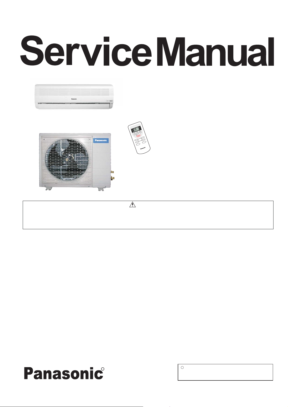
Room Air Conditioners
CS/CU-PA7DKD
CS/CU-PC7DKD
STD
MODE TEMP
OFF
CANCEL SET
FANSPEED
OFF/ON
ON
TIMER
AIRSWING
CS/CU-PA9DKD
CS/CU-PC9DKD
This service information is designed for experienced repair technicians only and is not designed for use by the general public.
It does not contain warnings or cautions to advise non-techical individuals of potential dangers in attempting to service a product.
Products powered by electricity should be serviced or repaired only by experienced professional technicians. Any attempt to service
or repair the product or products dealt with in this service information by anyone else could result in serious injury or death.
CONTENTS
1 Features 2
2 Functions 3
3 Product Specifications 6
4 Dimensions 14
5 Refrigeration Cycle Diagram 16
6 Block Diagram 17
7 Wiring Diagram 19
8 Operation Details 21
Installation
9
--------------------------------------------------------
------------------------------------------------------
------------------------------------------
-----------------------------------------------------
-----------------------------------
--------------------------------------------------
-------------------------------------------------
-----------------------------------------------
---------------------------------------------------
WARNING
Page Page
10 2-way,3-way Valve
11
Disassembly of The Parts
12 Troubleshooting Guide
13 Technical Data
14 Exploded View
15 Replacement Parts List
16 Exploded View
17 Replacement Parts List
18 Electronic Circuit Diagram
35
-----------------------------------------------------
--------------------------------------
----------------------------------------
--------------------------------------------------
--------------------------------------------------
-----------------------------------------
--------------------------------------------------
-----------------------------------------
--------------------------------------
49
56
59
61
64
65
66
67
68
C
R
R
Guangzhou Matsushita Air Conditioner Co., Ltd.
(GMAC) All rights reserved. Unauthorized copying
and distribution is violation of law.
Page 2

CS-PA7DKD / CU-PA7DKD / CS-PC7DKD / CU-PC7DKD
1 Features
High Efficiency
Air Quality Indicator
Auto Restart Control
Automatically restart after power failure
Comfort Environment
Air filter with function to reduce dust and smoke
12-hour Timer Setting
2
Page 3

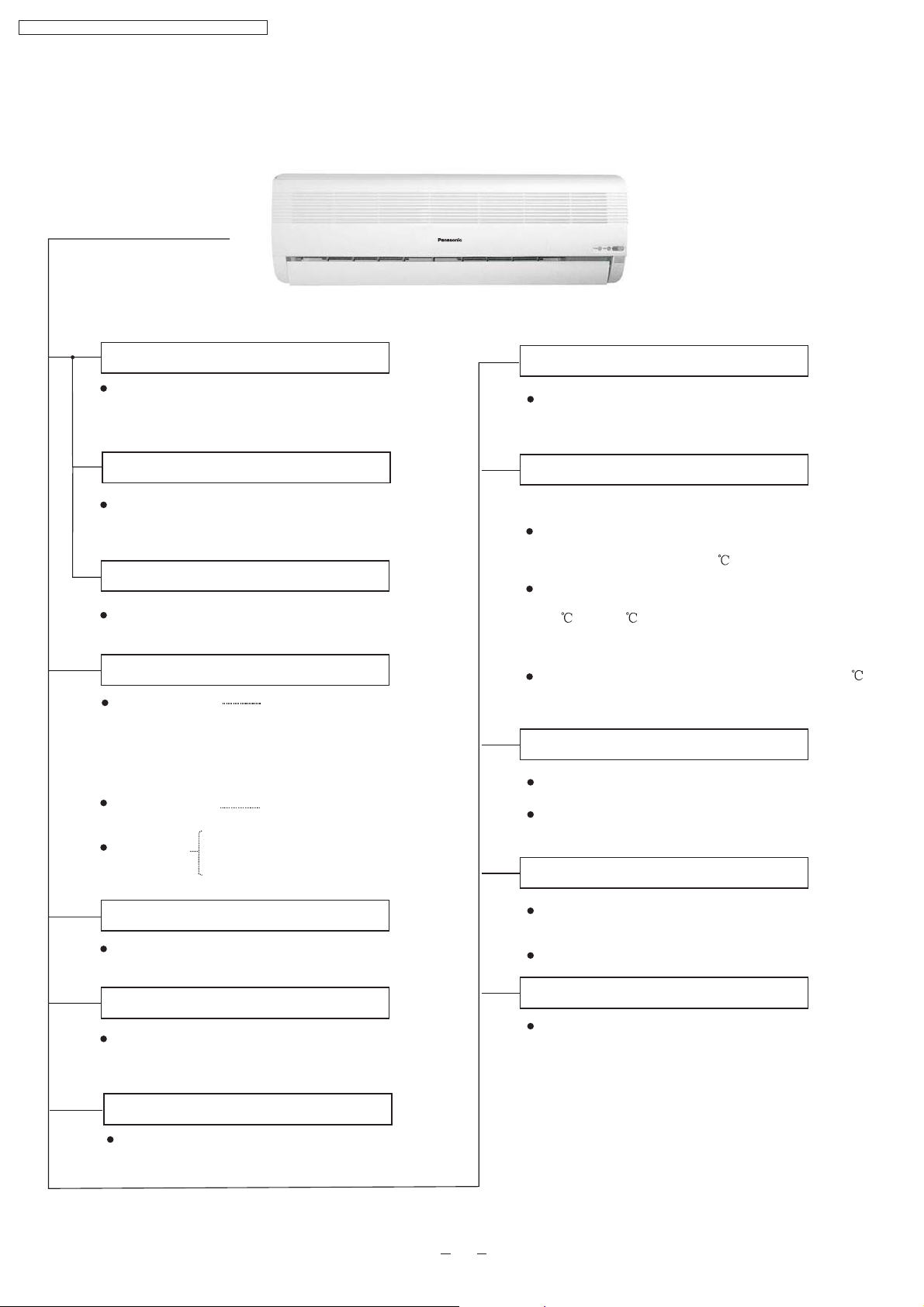
2 Functions
Remote Control
STD
MODE TEMP
OFF/ON
OFF
CANCEL SET
TIMER
FANSPEED
CS-PA7DKD / CU-PA7DKD / CS-PC7DKD / CU-PC7DKD
ON
AIR SWING
OFF/ON
MODE
FAN
SPEED
Operation START/STOP
Turn on/off the air conditionor
When stop the operation by pressing
OFF/ON button,the cursor key points
to OFF.
Operation Mode Selection
Automatic Operation
Heating Mode Operation
(For PA7DKD,PA9DKD)
Cooling Mode Operation
Soft Dry Mode Operation
Air Circulation Mode Operation
(For PC7DKD,PC9DKD)
Mode
Indoor Fan Speed Selection
Low Speed
Medium Speed
High Speed
Automatic Speed
Air
SWING
Airflow Direction Control
Horizontal Airflow Direction Control
-Auto Control
-Manual Control
Vertical Airflow Direction Manual Control
TEMP
Room Temperature Setting
Temperature Setting(16 to 30 )
Auto Operation
TIMER
OFF/ON
Timer Operation Selection
Stop/Start Operation Control
(set the ON/OFF Timer hourly later)
TIMER
SET/
CANCEL
Set /Cancel Timer Operation
Set timer/Cancel the set timer
By pressing SET button for 5seconds
continuously to switch to set the sensor
sensitivity.
3
Page 4
CS-PA7DKD / CU-PA7DKD / CS-PC7DKD / CU-PC7DKD
Indoor Unit
Auto Switch
Button
Power Switch ON/OFF
National
Anti-freezing Control for the Evaporator
When the remote control cannot be used or
for repairing and testing ,please use this
button.
Demonstration Mode
Keep pressing this button for 15seconds to start
or end the Demonstration Mode.
Signal Receiving Sound Control
Keep pressing this button for 10seconds to turn
on or turn off the signal receiving sound.
Operation Indication Lamps
Power (green)
Timer(orange)
Air quality
Green
Orange
Red
Lights up in operation;
Blinks during Test
Run operation and
determining Auto
Operation mode
Timer in operation
Cooling or Soft Dry Operation
Warm Booting Control
(For PA7DKD, PA9DKD only)
Indoor fan starts running when temperature
of evaporator reaches 30 or above.
When temperature of evaporator is between
30 and 34 ,indoor fan will run at Super Low
or Low speed.
When temperature of evaporator reaches 34 ,
Warm Booting Operation ends.
Indoor Fan Speed Control
High,Med,Low
Auto Fan Speed
Airflow Direction Control
Operation Mode
Cooling/Heating/Soft Dry /Auto Operation
/ Air circulation
Time Delay Safety Control
The unit will restart operation in 3-4
minutes after each pause.
7-Minutes Time Save Control
7-minutes automatic restarting at Cooling
Operation
Automatic Airflow Direction Control
The louver automatically swings up and down
Airflow Direction Manual Control
Delayed On-timer Control
For cooling or soft dry mode, the unit
starts 15 minutes before the set time with
the remote control, but for heating mode
30 minutes before the set time.
4
Page 5
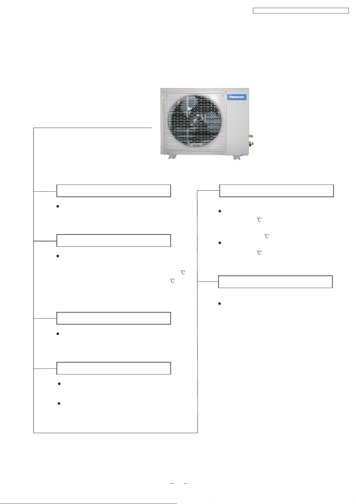
Outdoor Unit
CS-PA7DKD / CU-PA7DKD / CS-PC7DKD / CU-PC7DKD
Panasonic
Anti-reverse Protection
To protect the compressor from reverse
rotation when power off suddenly.
Overload Protector
The 2-step Overload Protector is to protect
the compressor when
1)Temperature of compressor reaches 150
(PA7DKD,PC7DKD,PA9DKD) or
(PC9DKD)
2)High temperature or current enters into the
compressor
145
60-seconds Test Operation Control
Once the compressor is activated, it does not
stop for 60 seconds. It stops immediately with
remote control ON/OFF button.
Overload Protection Control
(For PA7DKD,PA9DKD only)
When the temperature of evaporator
reaches 51 ,outdoor fan stops,and will
restart when the temperature of evaporator
declines to 49 .
When the temperature of evaporator
reaches 65 ,compressor will stop.
4-way Valve Control
(Only for PA7DKD,PA9DKD)
If the unit is stopped during Heating
Operation,the 4-way valve will remain in
heating mode operation for 5 minutes.
Deicing Control
Anti-freezing operation for outdoor unit(during
Heating Mode Operation only)
Temperature of the condenser is tested by TRS.
(For PA7DKD,PA9DKD only)
5
Page 6
CS-PA7DKD / CU-PA7DKD / CS-PC7DKD / CU-PC7DKD
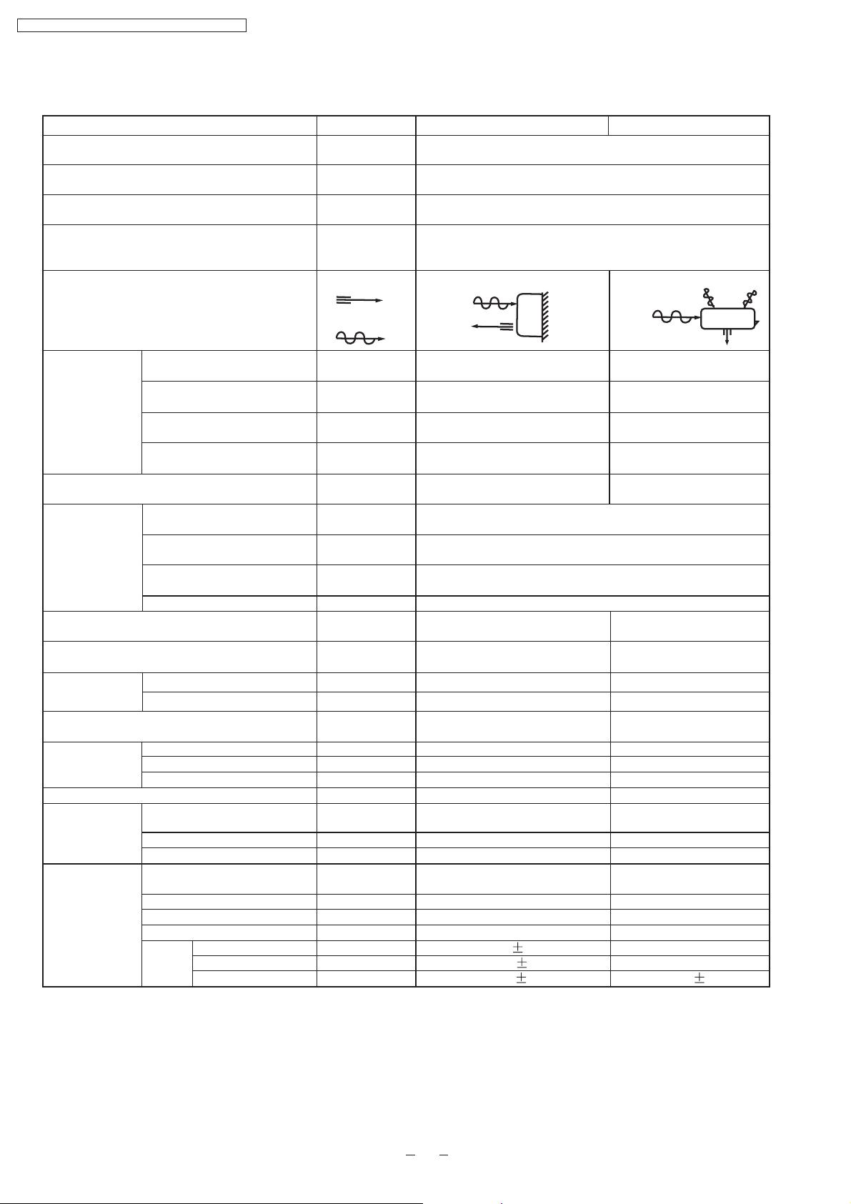
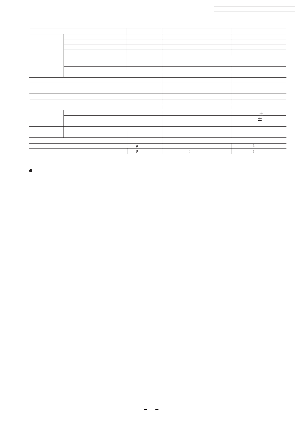
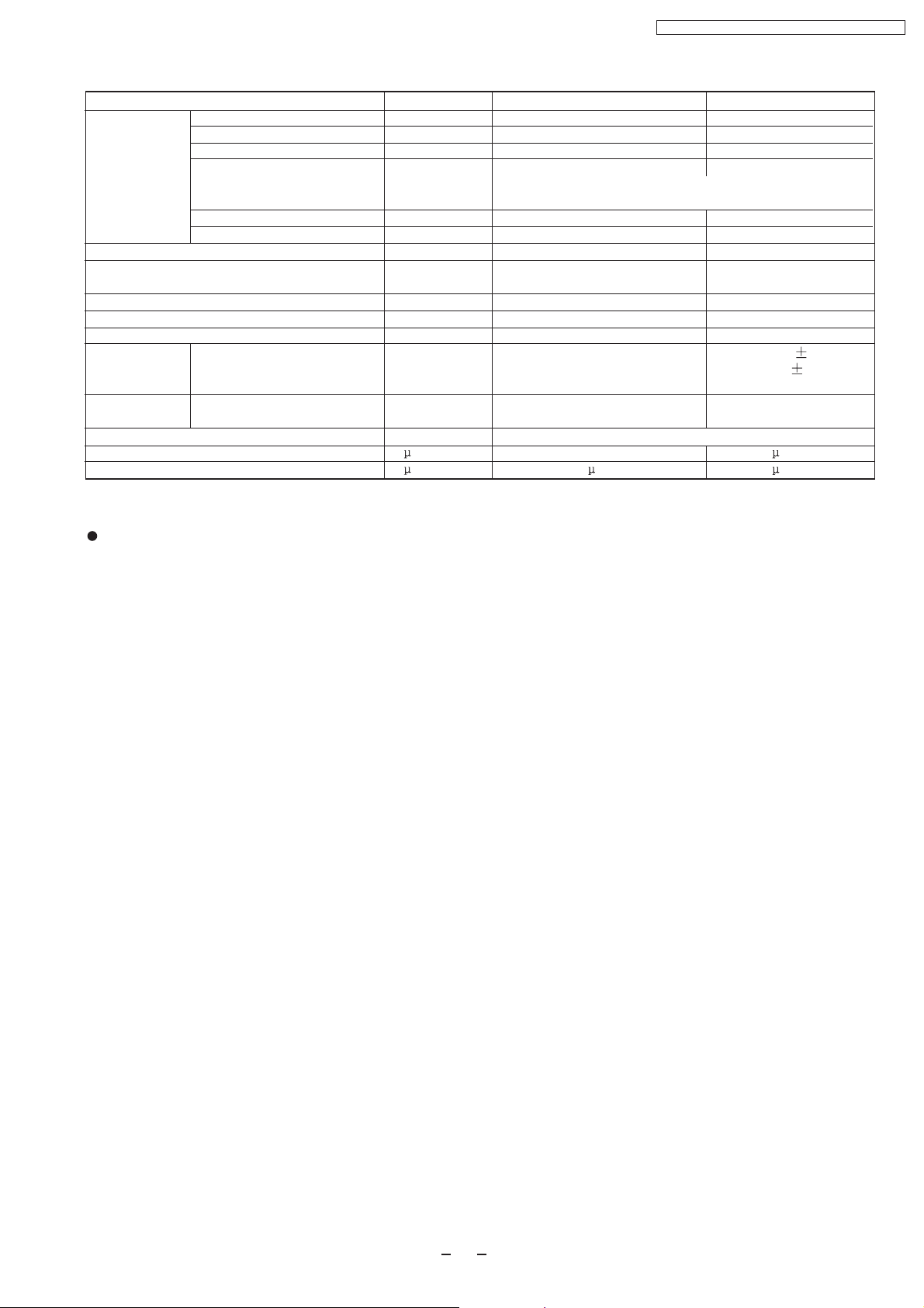
3 Product Specifications
Cooling Capacity
Heating Capacity
Moisture Removal
Power Source
Airflow Method
Air Circulation
Indoor Air (low)
Indoor Air (medium)
Indoor Air (high)
Outdoor Air
Noise Level
Electrical
Input
Data
Running Current
EER/COP
Starting Current
Piping Connection Port(Flare piping)
Piping Size(Flare piping)
Drain Hose
Inner Diameter
Length
Power Supply Cord Length
(Number of core-wire)
Dimensions
Height
Width
Depth
Net Weight
Compressor
Type
Motor Type
Rated output
Air Circulation
type
Motor type
Input
Rated Output
Fan
Speed
Low
Med
High
Unit
kW
kW
L/h
Phase
V
Cycle
OUTLET
INTAKE
3
m /min
3
m /min
3
m /min
3
m /min
dB(A)
W
A
W/W
A
Inch
Inch
Inch
Inch
mm
m
m
mm
mm
mm
kg
W
W
W
rpm
rpm
rpm
CS-PA7DKD CU-PA7DKD
2.10
2.30
1.2
Single
220
50
SIDE VIEW
TOP VIEW
7.40
8.66
9.50
-
Cooling:high37,Low29
Heating:high37,Low29
Cooling:high47
Heating:high48
Cooling:695
Heating:620
Cooling:3.40
Heating:3.00
Cooling:3.02
Heating:3.71
18
G:half union3/8"
L:half union1/4"
G:gas side3/8"
L:liquid side1/4"
G:3-way valve3/8"
L:2-way valve1/4"
G:gas side3/8"
L:liquid side1/4"
14
0.5
3 core-wire/1.0mm
1.3
250
770
205
2
530
650
230
7.5
-
-
-
-
-
-
Cross-flow fan
Induction(4 pole)
Rotary(1 cylinder)
Rolling piston type
Induction(2 pole)
600
Propeller fan
Induction(6 pole)
-
13
880 60
1030 60
1130 50
800 60
-
-
-
-
-
-
-
-
23
-
28
-
-
6
Page 7
Heat
Exchanger
Description
Tube Material
Fin Type
CS-PA7DKD / CU-PA7DKD / CS-PC7DKD / CU-PC7DKD
Unit CS-PA7DKD CU-PA7DKD
Evaporator
Copper
Slot type
Condenser
Copper
Corrugation type
Rows/Stage
(Plate fin configuration,forced draft)
2x12
FPI
Dimensions
Refrigerant Control Device
Refrigeration Oil
Refrigerant (R-22)
Thermostat
Protection Device
Length
Capillary
Circulation
Inner Diameter
Air Filter
mm
(c.c)
g
Electronic Control
mm
L/min
mm
P.P. Honeycomb
18
610x252x25.4
-
-
-
-
-
-
-
Refrigerant Circulation Control Device
Compressor Capacitor
Fan Motor Capacitor
F,V
F,V
1.5
-
F , 400V
* 60g for air purging is not included.
Specifications are subject to change without notice for further improvement.
1X24
17
269.1x504x18.19
Capillary Tube
SUNISO 4GDID or ATMOS
M60 or ATMOS 56M
530(*)
-
O.L.P.(230V,30A)
655 20
9.5 0.2
1.4
Capillary
20 370V
F,
F,2.0 400V
7
Page 8
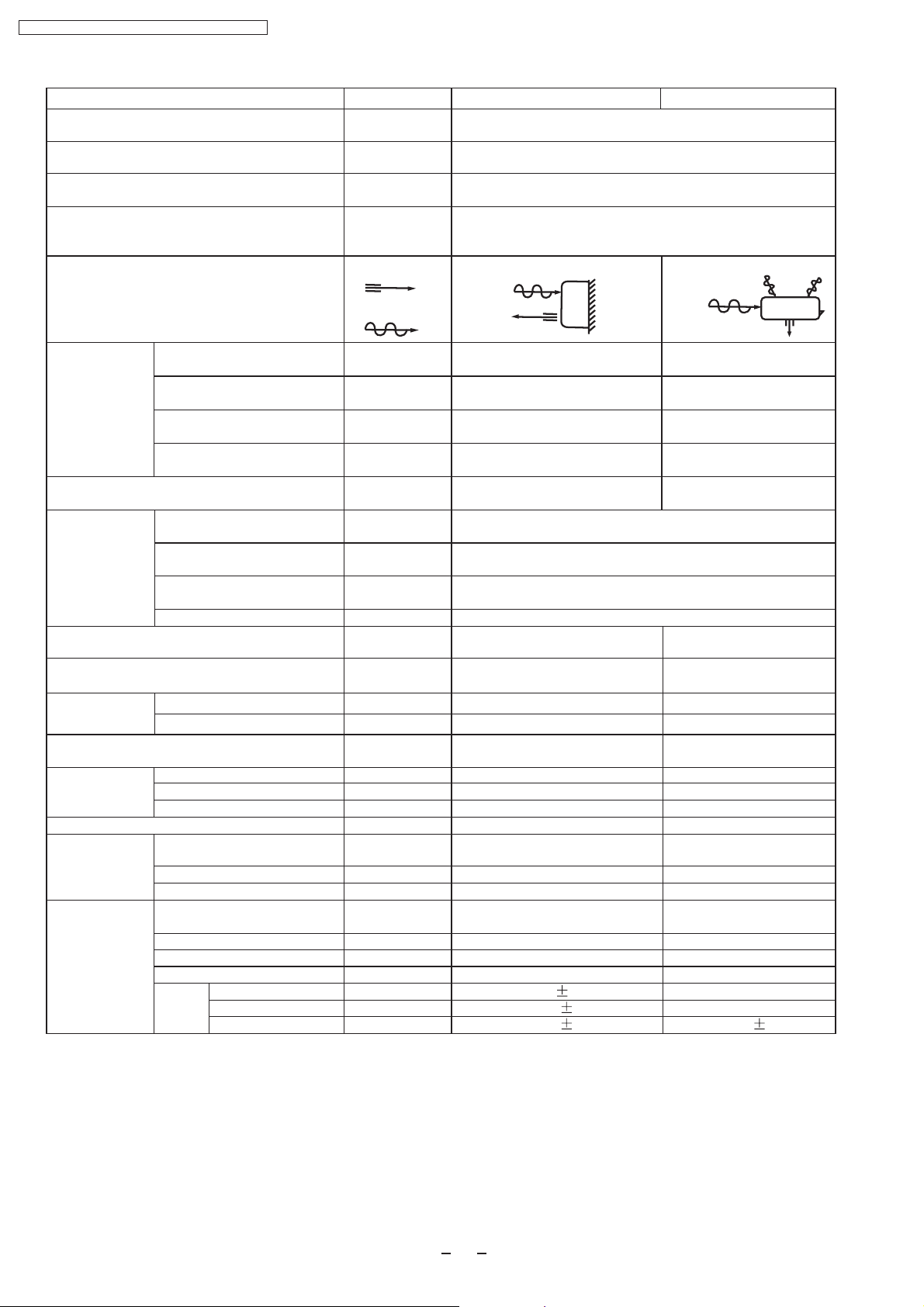
CS-PA7DKD / CU-PA7DKD / CS-PC7DKD / CU-PC7DKD
Cooling Capacity
Heating Capacity
Moisture Removal
Power Source
Airflow Method
Air Circulation
Indoor Air (low)
Indoor Air (medium)
Indoor Air (high)
Outdoor Air
Noise Level
Electrical
Input
Data
Running Current
EER/COP
Starting Current
Piping Connection Port(Flare piping)
Piping Size(Flare piping)
Drain Hose
Inner Diameter
Length
Power Supply Cord Length
(Number of core-wire)
Dimensions
Height
Width
Depth
Net Weight
Compressor
Type
Motor Type
Rated output
Air Circulation
type
Motor type
Input
Rated Output
Fan
Speed
Low
Med
High
Unit
kW
kW
L/h
Phase
V
Cycle
OUTLET
INTAKE
3
m /min
3
m /min
3
m /min
3
m /min
dB(A)
W
A
W/W
A
Inch
Inch
Inch
Inch
mm
m
m
mm
mm
mm
kg
W
W
W
rpm
rpm
rpm
CS-PA9DKD CU-PA9DKD
2.60-2.65
3.00-3.05
1.40
Single
220/230
50
SIDE VIEW
TOP VIEW
7.72
8.54
10.10
-
Cooling:high38,Low29
Heating:high38,Low29
Cooling:high47
Heating:high48
Cooling:830-850
Heating:790-820
Cooling:3.90-3.80
Heating:3.65-3.65
Cooling:3.13-3.12
Heating:3.80-3.72
16
G:half union3/8"
L:half union1/4"
G:gas side3/8"
L:liquid side1/4"
G:3-way valve3/8"
L:2-way valve1/4"
G:gas side3/8"
L:liquid side1/4"
14
0.5
3 core-wire/1.0mm
1.3
250
770
205
2
530
650
230
7.5
-
-
-
-
-
-
Cross-flow fan
Induction(4 pole)
Rotary(1 cylinder)
Rolling piston type
Induction(2 pole)
700
Propeller fan
Induction(6 pole)
-
13
940 60
1090 60
1230 60
800 60
-
-
-
-
-
-
-
-
27
-
28
-
-
8
Page 9
Heat
Exchanger
Description
Tube Material
Fin Type
CS-PA7DKD / CU-PA7DKD / CS-PC7DKD / CU-PC7DKD
Unit CS-PA9DKD CU-PA9DKD
Evaporator
Copper
Slot type
Condenser
Copper
Corrugation type
Rows/Stage
(Plate fin configuration,forced draft)
2x12
FPI
Dimensions
Refrigerant Control Device
Refrigeration Oil
Refrigerant (R-22)
Thermostat
Protection Device
Length
Capillary
Circulation
Inner Diameter
Air Filter
mm
(c.c)
g
Electronic Control
mm
L/min
mm
P.P. Honeycomb
18
610x252x25.4
-
-
-
-
-
-
-
Refrigerant Circulation Control Device
Compressor Capacitor
Fan Motor Capacitor
F,V
F,V
1.5
-
F , 400V
* 60g for air purging is not included.
Specifications are subject to change without notice for further improvement.
2X24
17
569.1
X504x36.38
540.5
Capillary Tube
SUNISO 4GDID or ATMOS
M60 or ATMOS 56M
860(*)
-
O.L.P.(230V,37A)
609 10
10.0 0.2
495 20
9.0 0.2
1.4
Capillary
F,30 370V
F,2.0 400V
1.3
9
Page 10
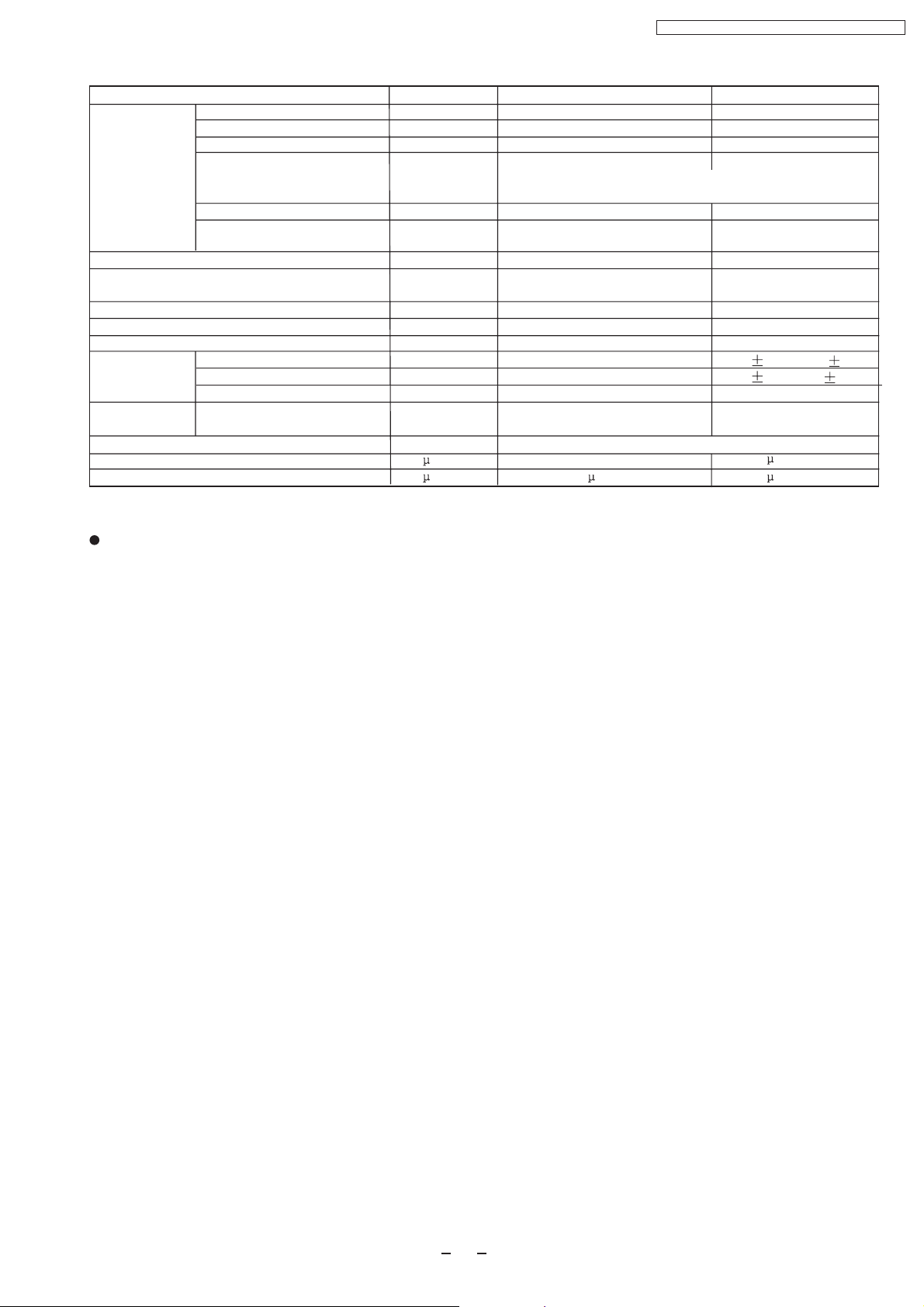
CS-PA7DKD / CU-PA7DKD / CS-PC7DKD / CU-PC7DKD
Cooling Capacity
Moisture Removal
Power Source
Airflow Method
Air Circulation
Indoor Air (low)
Indoor Air (medium)
Indoor Air (high)
Outdoor Air
Noise Level
Electrical
Input
Data
Running Current
EER
Starting Current
Piping Connection Port(Flare piping)
Piping Size(Flare piping)
Drain Hose
Inner Diameter
Length
Power Supply Cord Length
(Number of core-wire)
Dimensions
Height
Width
Depth
Net Weight
Compressor
Type
Motor Type
Rated Output
Air Circulation
Type
Motor Type
Input
Rated Output
Fan
Speed
Low
Med
High
Unit
kW
L/h
Phase
V
Cycle
OUTLET
INTAKE
3
m /min
3
m /min
3
m /min
3
m /min
dB(A)
W
A
W/W
A
Inch
inch
Inch
inch
mm
m
m
mm
mm
mm
kg
W
W
W
rpm
rpm
rpm
CS-PC7DKD CU-PC7DKD
2.10
1.20
Single
220
50
SIDE VIEW
TOP VIEW
4.9
5.7
6.8
-
High36,Low28
High47
680
3.20
3.09
15
G:half union3/8"
L:half union1/4"
G:gas side3/8"
L:liquid side1/4"
G:3-way valve3/8"
L:2-way valve1/4"
G:gas side3/8"
L:liquid side1/4"
14
0.5
1.3
3 core-wire/1.0mm
250
770
205
2
530
650
230
7.5
-
-
-
-
-
-
Cross-flow fan
Induction(4 pole)
Rotary(1 cylinder)
Rolling piston type
Induction(2 pole)
660
Propeller fan
Induction(6pole)
-
13
810 60
940 60
1130 60
800 60
-
-
-
-
-
-
-
-
21
-
28
-
-
10
Page 11
Heat
Exchanger
Description
Tube Material
Fin Type
CS-PA7DKD / CU-PA7DKD / CS-PC7DKD / CU-PC7DKD
Unit CS-PC7DKD CU-PC7DKD
Evaporator
copper
slot type
Condenser
copper
Corrugation type
Rows/Stage
(Plate fin configuration,forced draft)
2x8 1x24
FPI
Dimensions
Refrigerant Control Device
Refrigeration Oil
Refrigerant (R-22)
Thermostat
Protection Device
Length
Capillary
Circulation
Inner Diameter
Air Filter
mm
(c.c)
g
Electronic Control
mm
L/min
mm
P.P Honeycomb
18
610x168x25.4
-
-
-
-
-
-
-
Refrigerant Circulation Control Device
Compressor Capacitor
Fan Motor Capacitor
F, V
F, V
-
* 60g for air purging is not included.
Specifications are subject to change without notice for further improvement.
17
575.8x504x12.7
Capillary Tube
SUNISO 4GDID or
ATMOS M60(M56)
450(*)
O.L.P.(25A/230V)
810 10
7.0 0.2
1.3
-
Capillary
F,20 400V
F,2.0 400VF,1.5 400V
11
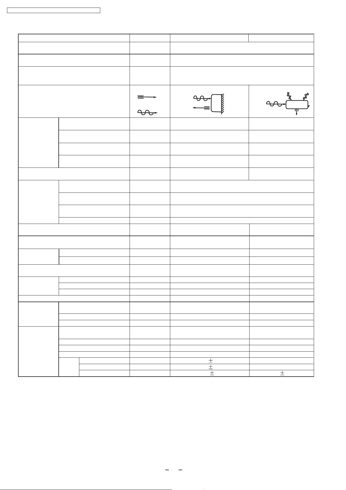
Page 12

CS-PA7DKD / CU-PA7DKD / CS-PC7DKD / CU-PC7DKD
Cooling Capacity
Moisture Removal
Power Source
Airflow Method
Air Circulation
Indoor Air (low)
Indoor Air (medium)
Indoor Air (high)
Outdoor Air
Noise Level
Electrical
Input
Data
Running Current
Unit
kW
L/h
Phase
V
Cycle
OUTLET
INTAKE
3
m /min
3
m /min
3
m /min
3
m /min
dB(A)
W
A
CS-PC9DKD CU-PC9DKD
2.50
1.40
Single
220 / 230
50
SIDE VIEW
TOP VIEW
6.5
7.4
8.5
-
High30,Low28
High48
860
4.00
-
-
-
-
EER
Starting Current
Piping Connection Port(Flare piping)
Piping Size(Flare piping)
Drain Hose
Inner Diameter
Length
Power Supply Cord Length
(Number of core-wire)
Dimensions
Height
Width
Depth
Net Weight
Compressor
Type
Motor Type
Rated Output
Air Circulation
Type
Motor Type
Input
Rated Output
Fan
Speed
Low
Med
High
W/W
A
Inch
inch
Inch
inch
mm
m
m
mm
mm
mm
kg
W
W
W
rpm
rpm
rpm
G:half union3/8"
L:half union1/4"
G:gas side3/8"
L:liquid side1/4"
14
0.5
1.3
3 core-wire/1.0mm
250
770
205
7.5
-
-
-
-
-
-
Cross-flow fan
Induction(4 pole)
-
13
870 60
980 60
1130 60
2.91
20.0
2
G:3-way valve3/8"
L:2-way valve1/4"
G:gas side3/8"
L:liquid side1/4"
-
-
-
530
650
230
23
Rotary(1 cylinder)
Rolling piston type
Induction(2 pole)
750
Propeller fan
Induction(6pole)
-
28
-
-
800 60
12
Page 13

CS-PA7DKD / CU-PA7DKD / CS-PC7DKD / CU-PC7DKD
Unit CS-PC9DKD CU-PC9DKD
Heat
Exchanger
Description
Tube Material
Fin Type
Rows/Stage
FPI
Dimensions
Refrigerant Control Device
Refrigeration Oil
Refrigerant (R-22)
Thermostat
Protection Device
Length
Capillary
Circulation
Inner Diameter
Air Filter
(Plate fin configuration,forced draft)
mm
(c.c)
g
mm
L/min
mm
Evaporator
copper
slot type
2x12
18
610x252x25.4
-
-
-
Electronic Control
-
-
-
-
P.P Honeycomb
Refrigerant Circulation Control Device
Compressor Capacitor
Fan Motor Capacitor
F, V
F, V
-
* 60g for air purging is not included.
Specifications are subject to change without notice for further improvement.
Condenser
copper
Corrugation type
1x24
17
575.8x504x12.7
Capillary Tube
SUNISO 4GDID or
ATMOS M60(M56)
430(*)
O.L.P.(30A/230V)
590 20
10.1 0.2
1.4
-
Capillary
F,25 370V
F,2.0 400VF,1.5 400V
13
Page 14

CS-PA7DKD / CU-PA7DKD / CS-PC7DKD / CU-PC7DKD
4 Dimensions
Indoor Unit
Unit : mm
Side view
Left Piping
Hole
Air intake
Air outlet
Front View
250
<Back View>
770
Installation Plate Hook
61
Gas Side
165
Liquid
Side
49
205
49
CANCEL
FANSPEED
Right Piping
Hole
61
5
STD
TEMP
MODE
OFF/ON
ON
OFF
TIMER
AIRSWING
125
SET
(79)
(410)
(43)
Drain Port
Relative position between the unit and the installation plate (Front View)
229
118.8
15.5
20
6
26.5
E
B
C
D
B
(382)
(452)
(680)
15.5
20
6
26.5
109.2
D
B
144.2
56
16.5
14
Page 15
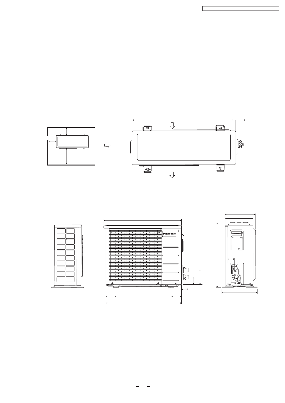
Outdoor Unit
CU-PA7DKD
CU-PA9DKD
CU-PC7DKD
CU-PC9DKD
CS-PA7DKD / CU-PA7DKD / CS-PC7DKD / CU-PC7DKD
Unit : mm
<Top View>
Required space for installation
10cm
10cm
100cm
<Front View>
668
650
Air intake
Air outlet
<Side View>
61.6
250
230
88 88
650
15
61.6
62.2
123.8
530
55.8
293
Page 16
INTAKE AIR
SENSOR
PIPING
SENSOR
PIPING
SENSOR
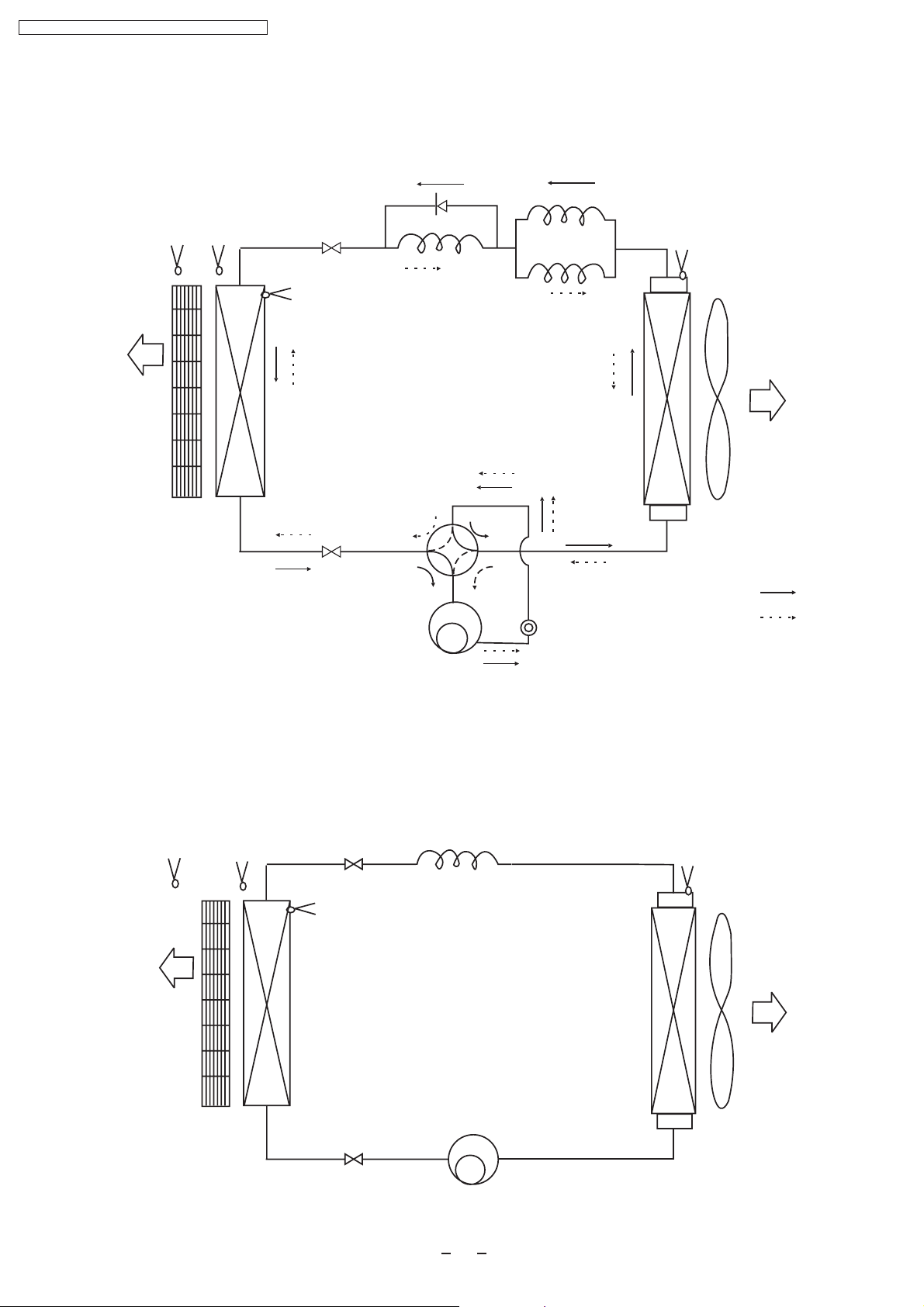
CS-PA7DKD / CU-PA7DKD / CS-PC7DKD / CU-PC7DKD
5 Refrigeration Cycle Diagram
CS/CU-PA7DKD
CS/CU-PA9DKD
AIR QUALITY
SENSOR
INTAKE AIR
SENSOR
PIPING
SENSOR
PIPING
SENSOR
4-way valve
Cooling
Heating
CS/CU-PC7DKD
CS/CU-PC9DKD
INTAKE AIR
AIR QUALITY
SENSOR
SENSOR
PIPING
SENSOR
PIPING
SENSOR
16
Page 17
6 Block Diagram
CS-PA7DKD/CU-PA7DKD
CS-PA9DKD/CU-PA9DKD
O.L.P.
FM
CS-PA7DKD / CU-PA7DKD / CS-PC7DKD / CU-PC7DKD
Compressor
OUTDOOR UNIT
INDOOR UNIT
4-Valve
4
SSR202
RY-HOT
Remote
3
CR201
SSR201
FM
Control
1
RY-PWR
Piping Sensor
2
FM
FUSE
Receiver
POWER SUPPLY
Indicator
Sensor
For PA7DKD, the power source is 220V.
For PA9DKD, the power source is 220V-230V .
AC220V-230V 50Hz
17
Page 18
CS-PA7DKD / CU-PA7DKD / CS-PC7DKD / CU-PC7DKD
CS-PC7DKD/CU-PC7DKD
CS-PC9DKD/CU-PC9DKD
Compressor
FM
RY-PWR
FUSE
Remote
Control
Receiver
POWER SUPPLY
FM
AC220V-230V 50Hz
SC
SSR201
Indicator
Sensor
For PC7DKD, the power source is 220V.
For PC9DKD, the power source is 220V-230V .
18
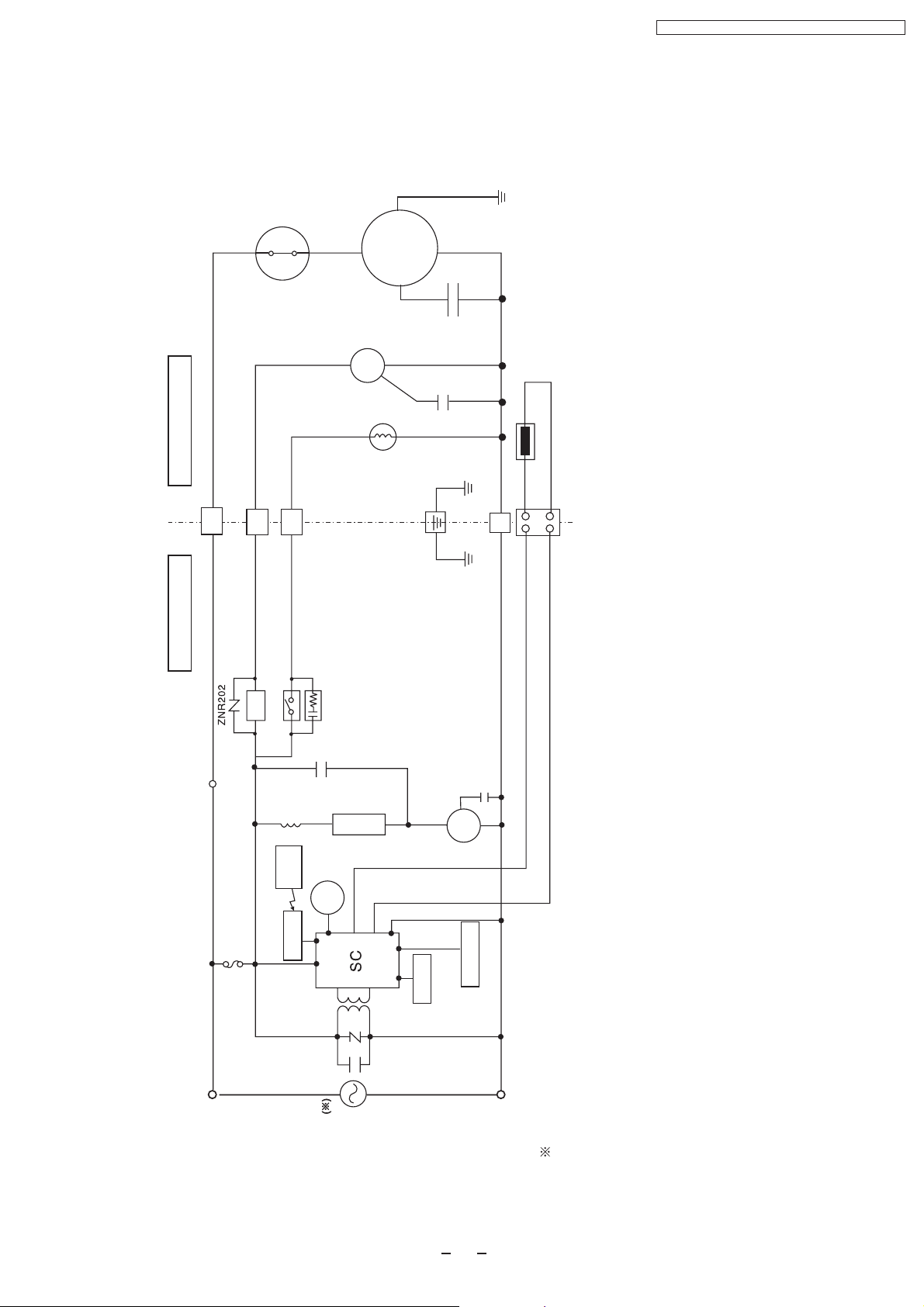
Page 19
POWER SUPPLY
CORD
AC 220V-230 50Hz( )
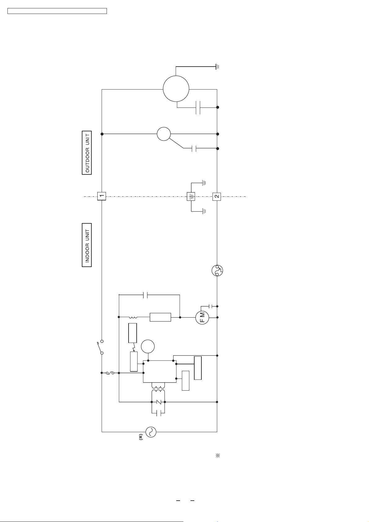
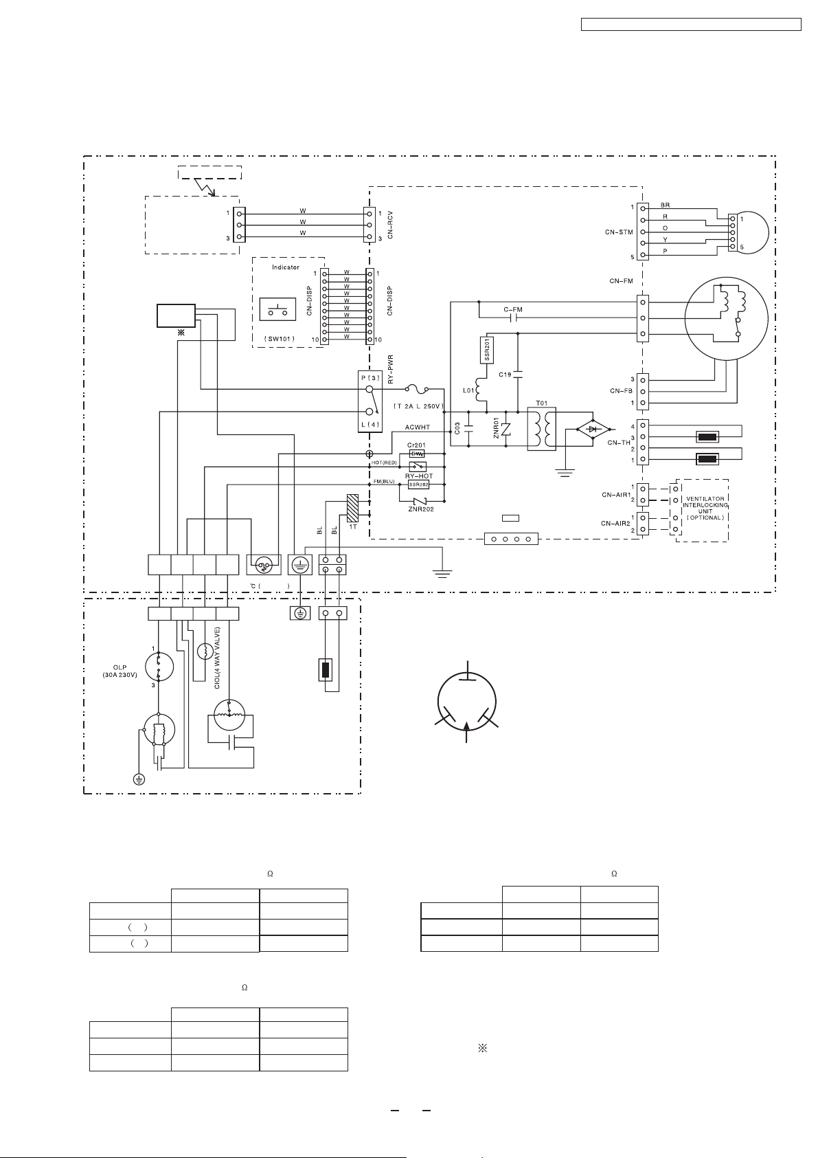
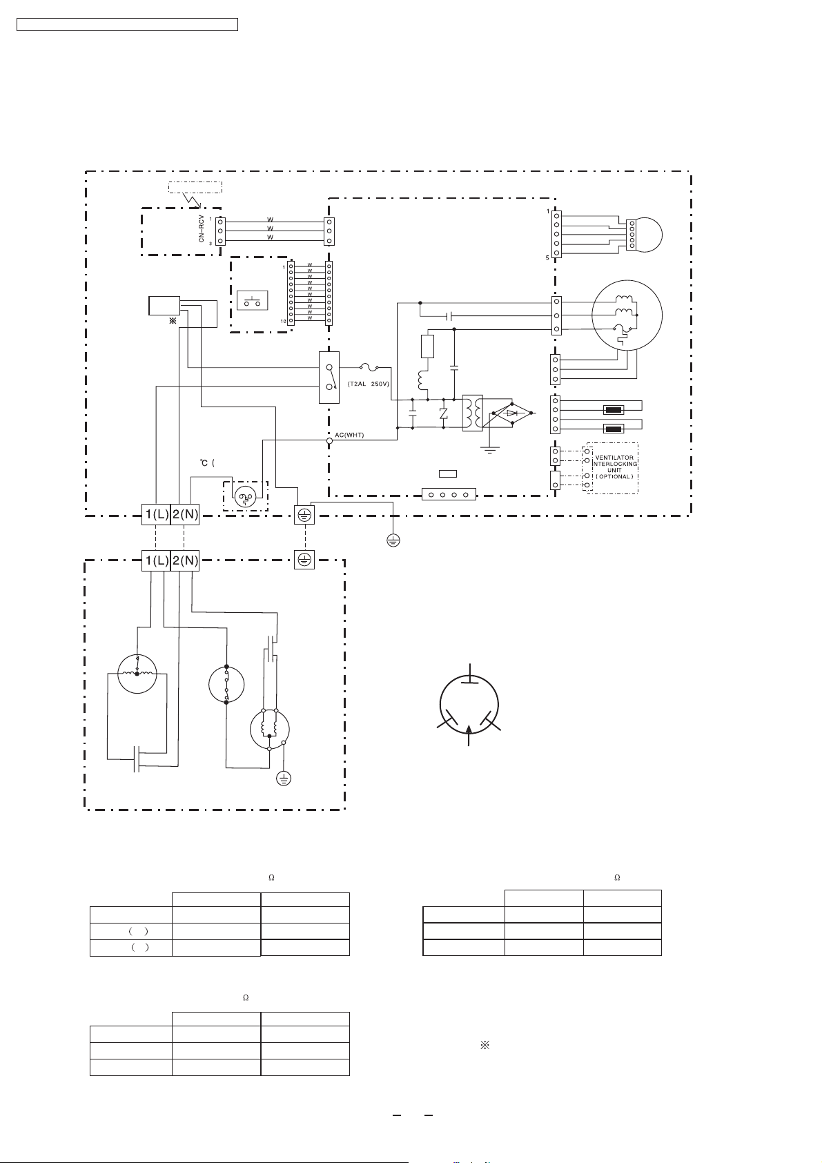
7 Wiring Diagram
CS-PA7DKD/CU-PA7DKD
CS-PA9DKD/CU-PA9DKD
Remote Control
CS-PA7DKD / CU-PA7DKD / CS-PC7DKD / CU-PC7DKD
POWER SUPPLY
AC 220V-230 50Hz( )
INDOOR UNIT
TERMINAL BOARD
Signal Receiver
CORD
B
1(L) 2(N) 3 4
CN-RCV
Y/G
102 250V 3A
AUTO SWITCH
BR
BL
FUSE
ELECTRONIC CONTROLLER
STEPPING
MOTOR
1
B
3
R
5
Y
FAN MOTOR
W
FUSE
W
R
B
HA
1234
Y/G
BR
BL
SENSOR(PIPING TEMP.)
SENSOR(INTAKETEMP.)
INDOOR UNIT
OUTDOOR UNIT
TERMINAL BOARD
COMPRESSOR
1(L) 2(N) 3 4
YW
Y
Y/G
R
CAPACITOR
Y
FAN MOTOR
R
B
B
CAPACITOR
B
OUTDOOR UNIT
INDOOR FAN MOTOR RESISTANCE( )
CS-PA7DKD CS-PA9DKD
CONNECTING
Y-B M
Y-R A
COMPRESSOR RESISTANCE( )
CWA921308 CWA921329
395
325
390
390
R : RED
BL : BLACK
YELLOW
C
B : BLUE
BR : BROWN
O : ORANGE
SENSOR(PIPING TEMP.)
R
BLUE
TRADE MARK
S
RED
COMPRESSOR TERMINAL
OUTDOOR FAN MOTOR RESISTANCE( )
GRY : GREY
G : GREEN
Y : YELLOW
W : WHITE
Y/G : YELLOW/GREEN
P : PINK
CU-PA7DKD CU-PA9DKD
CONNECTING
Y-B
Y-R
CWA951419 CWA951419
275
260
275
260
CONNECTING
C-R
C-S
CU-PA7DKD CU-PA9DKD
CWB092128
3.678
7.240
CWB092312
3.466
3.843
For PA7DKD, the power source is 220V.
For PA9DKD, the power source is 220V-230V .
19
Page 20
POWER SUPPLY
CORD
CS-PA7DKD / CU-PA7DKD / CS-PC7DKD / CU-PC7DKD
AC 220V-230 50Hz( )
CS-PC7DKD/CU-PC7DKD
CS-PC9DKD/CU-PC9DKD
REMOTE CONTROL
SIGNALRECEIVER
POWER SUPPLY
CORD
AC 220V-230 50Hz( )
INDOOR UNIT
TERMINAL BOARD
OUTDOOR UNIT
TERMINAL BOARD
Y
FAN MOTOR
R
B
CAPACITOR
B
FUSE
102 250V 3A)
OUTDOOR UNIT
B
Y
O.L.P
INDICATOR
CN-DISP
AUTO SWITCH
(SW 01)
BR
BL
Y/G
W
B
Capacitor
1
R
B
3
Y
COMPRESSOR
Y/G
OUTDOOR UNIT
ELECTRONIC CONTROLLER
1
CN-RCV
3
1
P(3)
L(4)
CN-DISP
10
RY-PWR
FUSE
Y/G
L01
C03
C-FM
SSR01
C19
ZNR01
HA
1234
YELLOW
R
BLUE
TRADE MARK
T01
COMPRESSOR TERMINAL
BR
R
CN-FM
CN-STM
1
3
5
3
CN-FB
1
4
3
2
1
1
CN-AIR1 CN-TH
2
1
2
CN-AIR2
O
Y
P
B
R
Y
W
BR
BL
SENSOR(PIPING TEMP.)
SENSOR(INTAKETEMP.)
FAN MOTOR
STEPPING
MOTOR
INDOOR UNIT
R : RED
BL : BLACK
B : BLUE
C
S
RED
BR : BROWN
O : ORANGE
GRY : GREY
G : GREEN
Y : YELLOW
W : WHITE
Y/G : YELLOW/GREEN
P : PINK
INDOOR FAN MOTOR RESISTANCE( )
CS-PC7DKD CS-PC9DKD
CONNECTING
Y-B M
Y-R A
COMPRESSOR RESISTANCE( )
CWA921308
395
325
CU-PC7DKD CU-PC9DKD
CONNECTING
C-R
C-S
CWB092129
4.307
7.668
CWA921329
390
390
CWB092279
3.072
5.216
OUTDOOR FAN MOTOR RESISTANCE( )
CU-PC7DKD CU-PC9DKD
CONNECTING
Y-B
Y-R
CWA951427
275
260
For PC7DKD, the power source is 220V.
For PC9DKD, the power source is 220V-230V .
20
CWA951427
275
260
Page 21

CS-PA7DKD / CU-PA7DKD / CS-PC7DKD / CU-PC7DKD
8 Operation Details
8.1 .Cooling Mode Operation
When selecting the Cooling Mode Operation, the unit will operate according to the setting by the Remote Controller or
the control panel on the indoor unit and the operation is as the following.
Time Delay Safety Control
3 min.----If the compressor stops, it will not restart within 3 minutes.(Protection of compressor).
7 Minutes Time Save Control
7 min.----The unit will automatically operate in 7 minutes even if the room temperature is not reached.
(Prevention of raising the humidity)
Anti-Freezing Control
If temperature of evaporator is lower than 2 continuously
Evaporator
Temperature
()
for 4 minutes, the compressor will cease to prevent the
evaporator from freezing. Fan speed setting will not be
changed.
When temperature of evaporator reaches 10 ,compressor
will restart.
During Cooling Mode Operation, the Time Delay Safety
Control is available.
Time
Automatic Fan Speed Mode
During Cooling Mode Operation, use remote controller to select Automatic Fan Speed.
Fan speed will be at the point between "High speed" and "Medium speed".
Deodorization control.
1
Indoor Fan
STOP
Slow
Slow
STOP STOP
Slow Slow
10
4 minutes
2
Compressor ceases
2
Restart
40 30 40 3020 160
Compressor
ON
STOP
1 Fan speed will be at Hi till the compressor ceases (set temperature reached).
2 Fan speed will be at Me when the compressor restarts.
21
ON
Page 22
CS-PA7DKD / CU-PA7DKD / CS-PC7DKD / CU-PC7DKD
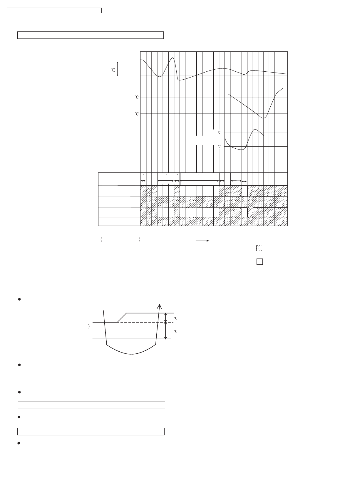
Time Graph for Cooling Operation
Intake air temperature
Set temperature
1.5
Basic Time
Comp.
Indoor Fan
Outdoor Fan
abcdefghi j klmnopqrstuvwxyz
Start
Stop
31
29
10
2
1’
3
4’
1 1
3
Evaporater
temperature
7
Operation Indicator
Operation status
d-g
g-h
h-o
q-t
:
Time delay safety control
:
Compressor Test control
:
Auto restart control
:
Anti-freezing Control
Time
Operate
Stop
8.2. Soft Dry Mode Operation
Operation area
COOLING
COOLING(OFF)
DRY(ON
DRY
DRY(OFF)
DRY(OFF)
When selecting Soft Dry mode operation, the operation will be cooling until the room temperature reaches the set temp on
remote control, and then Soft Dry will be activated. (During Soft Dry Mode the fan of indoor unit will operate at super low
speed. The soft dry mode will run for less than 10 minutes.)
Once Soft Dry mode operation is turned off, indoor fan, compressor and outdoor fan will stop for 6 minutes.
COOLING(ON)
1.5
1.0
DRY(ON)
Time Delay Safety Protection
During cooling mode operation, if the compressor ceased, it will not restart within 3 minutes.
Anti Freezing Control
Same as the denotation in Cooling Operation.( )
P21
(During Soft Dry Mode Operation, compressor will stop for at least 6 min.)
22
Page 23

Automatic Fan Speed
During Soft Dry Operation, use remote controller to select Auto Fan Speed mode.
Indoor Fan Speed is at “Lo-”
CS-PA7DKD/CU-PC7DKD / CS-PC7DKD/CU-PC7DKD
Lo-
Slo
Indoor
fan
OFF
T1
40
T2
70
10
Compressor
ON
Time Graph for soft dry operation
Intake Air temp
Cooling mode operation activated
1.5
1.0
Cooling mode operation stopped
Soft mode operation activated
Soft dry mode operation stop
Lo-
Slo Slo
OFF OFF OFF
T1
40
6
T2
70
10
ON
OFF
abcdef g hi jklmnopq rst u
Basic Time
Comp.
Indoor Fan
Outdoor Fan
Operation Indicator
4-way Valve
Operation status
a-c,p-r
c-p,r-u
e-f
j-l
q-t
:
Cooling Mode Operation
Soft Dry Mode Operation
:
:
Soft Dry Mode Operation Stopped
Compressor Test Operation Control
:
:
Anti Freezing Control
Evaporator
temperature
61 1 4
1
Super
Super
Super
Slo Slo Slo Slo
Low
Low
Low
Super
Low
Low
Slo Slo
Slo Slo Slo
Time
o
10 C
o
2C
666
Slo
Slo
Cooling mode operation
Soft Dry Mode operation
Operate
Stop
23
Page 24

Super Low
Indoor Fan
Stop
Indoor Heat
Exchanger
()
CS-PA7DKD / CU-PA7DKD / CS-PC7DKD / CU-PC7DKD
8.3. Heating Mode Operation(Only for PA7DKD,PA9DKD)
When selecting the Heating Mode Operation, the unit will operate according to the setting by the Remote Controller and
the operation is as the following.
Time Delay Safety Control
If the compressor stopped by switching off, turning off by remote controller, or power off, it will not restart within 3 minutes.
When room temperature reaches the set temperature on the remote controller, compressor stops and will not restart within
4 minutes.
3 minutes after the compressor stopped, indoor fan will stop for 1 minute. Then indoor fan will resume operation with the
speed at ”super low”
Over Load protection Control
When temperature of indoor heat exchanger rises to 51 , outdoor fan will stop
when temperature of indoor heat exchanger falls to 49 , outdoor fan will restart.
When temperature of indoor heat exchanger rises to 65 or above, compressor stops, and will restart 4 minutes later.
.
Compressor
Indoor Heat Exchanger 65
Anti-reversing Control
If the compressor has been continuously running for 5 minutes or longer, and the difference of temperature between
intake air and evaporator is continuously lower than 5.0 or below for 2 minutes, the compressor will stop , and then
restart 3 minutes later.(Time Delay Protection Control is effective.)
Compressor runs 5 min
T 5 last for 2 min
T= intake air temperature - evaporator temperature
4-way valve control
During heating mode operation,4-way valve is at open mode.
During heating mode operation,if the unit turned off, the 4-way valve will remain
at open mode for 5 minutes.
Stops
Compressor
Stops
Compressor Restarts
4 minutes later
Compressor Restarts
3 minutes later
Warm Booting Control
When turning on the unit by heating mode operation,indoor fan
will be activated when temperature of indoor heat exchanger
reaches 30 . (See the figure on the right)
Warm boot operation ends when temperature of indoor heat
exchanger reaches 34 .
24
Indoor Heat
Exchanger
()
34
30
Low
Super Low
Indoor Fan
Stop
Page 25

Automatic Fan Speed
S Lo
()
()
45
41
34
30
38
30
28
15
Temperature of heat exchanger
During Heating Operation, use remote controller to select Auto Fan Speed mode.
Indoor Fan Speed is between “Me” and “Slo”.
()
SLo
Me
Lo
Lo-
()
38
30
28
45
41
34
30
CS-PA7DKD / CU-PA7DKD / CS-PC7DKD / CU-PC7DKD
Temperature of heat exchanger
Time Graph for Heating Operation
abcdefghi jk
42
Indoor heat
exchanget
Temp.
Intake Temp.
34
32
30
OFF
2
ON
Basic Time
Compressor
Indoor Fan
Outdoor Fan
Operation Indicator
4-way valve
<Operation status>
a-b
c-d
h-k,o-r
:
Warm booting control(indoor fan Off)
:
Warm booting control(indoor fan Super Slo)
:
Prevent cool airEORZLQJRXW
Stop
30'
58''
1'
Tim e
15
l
nop qr
m
30
Manual fan speed
Blink
Operate
Stop
150'
25
Page 26

Deicing Operation Time(T)
3
min
3min T 7min
7
min T 9min
T 9min
Td(s)
0
60
120
180
<Operation status>
CS-PA7DKD / CU-PA7DKD / CS-PC7DKD / CU-PC7DKD
Deice Control
Deice operation is to protect the outdoor unit from freezing.
Normal Deice Operation
Deicing starts 30 minutes after heating mode operation or 60 minutes after the latest deicing operation. If temperature of
outdoor piping, tested by TRS, falls to -3 (TRS OFF) or below for continuously 50 seconds, deicing operation starts.
Overload Deicing Operation
During heating operation, if the accumulative stopping time of outdoor fan reaches 60 minutes,
deicing operation will start 1 minute after compressor starts.
Deicing operation ends under conditions below
(a) After 12 minutes.
(b) Temperature of outdoor unit rises to 4 .
(c) As the illustration showed bellow and due to Time Delay (Td), deicing won’t ends immediately.
Deicing Operation Time(T)
3min
3min T 7min
7 min T 9min
T 9min
Td(s)
0
60
120
180
Once deicing operation starts, it won’t end until 60 seconds later.
When deicing operation ends, compressor will stop for 30 seconds, and 4-way valve remains at cooling mode operation
for 10 seconds.
Time Graph for Normal Deicing Operation
Lo
max60'
l
nopq r s t uvwxy z
m
max12'
Slo
or
Blink
Operat io n
Stop
max60'
Lo
42
34
30
Indoor Piping Temp.
Basic Time
Compressor
Indoor Fan
Outdoor Fan
Operation LED
4-way valve
abcd ef gh i j k
60'
max12'
10S20S 20S 20S 20S 20S 10S 20STd
Slo
Time
<Operation status>
a-c Deicing confirmation
c-g Deicing operation(time reset)
h-j,u-w Warm Booting
o-r Deicing(TRS )
26
Page 27

Time Graph for Overload Deicing
Outdoor Heat
Exchanger
CS-PA7DKD / CU-PA7DKD / CS-PC7DKD / CU-PC7DKD
Outdoor Heat
Exchanger
Basic time
Compressor
abcdefghi j k
51
49
Out door fan stop for 60' accumulatively
20’’ 20’’
Max
12’
l
m
10’’ 20’’
nopq
Indoor fan
Outdoor fan
Operation Indicator
4-way valve
<Operation status>
Overload controla-i
i-l Overload deicing(timer)
l-m: Warm booting control
m-r Overload control
Time
Blin k
Oper ati on
Stop
27
Page 28

CS-PA7DKD / CU-PA7DKD / CS-PC7DKD / CU-PC7DKD
8.4. Automatic Mode Operation
Standard for Determining Operation Mode
First Determination:
Setting Temperature (Standard)
25
22
21
Intake Air
temperature
23
20
Cooling mode
Soft Dry mode
Heating mode
Cooling mode
Soft Dry mode
Heating mode
Second Determination:
One hour after the above determination, the unit will operate according to the table below.
Second Determination
Cooling
Cooling
First
determination
A)
Indoor fan operates at super low speed for 25 seconds.
B)
After judging indoor air temperature, the operation is determined and operation continued at the mode determined.
C)
If indoor temperature is less than 16 , heating operation will immediately operate.
D)
After the operation mode has been determined, the mode does not change. However,Soft Dry mode operation
includes cooling mode operation.
E)
If automatic mode operation is started while the unit is operating,operation will continue.
If current operation is in cooling mode (including the cooling mode operation when is a part of Soft Dry mode
operation) it will be maintained, and if current operation is not cooling mode, the appropriate operation mode is
determined for 25seconds at super slow fan speed.Then the selected mode will continue.
F)
Room temperature adjustment
Dry
Heating
Higher
23 or above
25 or above
2
Dry
20 or above
Heating
23 below
20 below
25 below
Standard
Lower
0
2
8.5. Air Circulation Mode Operation(Only for PC7DKD,PC9DKD)
1. An additional heater may make the warm air evenly covering each corner of the room.
2. When the temperature near the ceiling reaches the setting temperature, Air Circulation Mode Operation commences
at low airflow volume. It stops when the temperature drops to 2 below the setting temperature.
3. The vertical airflow direction louver will not swing.
28
Page 29

CS-PA7DKD / CU-PA7DKD / CS-PC7DKD / CU-PC7DKD
8.6 Air Quality Sensor Control
Resistance of air quality sensor: Rs(air)=10k ~50k ( The worse the air quality, the smaller the resistance.)
Basic Operation
Detecting and indicating of the air quality will not stop during the operation of the air conditioner.
The power of the air quality sensor is always on during the operation of the air conditioner. When the air
conditioner stops (The air conditioner is on standby.), the air conditioner will provide power to the air quality
sensor intermittently (It will be on for 3 minutes after each 109 minutes.) for the purpose of air quality detecting.
Within 2 minutes after the air conditioner starts to operate, the air quality sensor is in the process of preheating
and the air quality indicator is red.
Resistance Reference
Detecting of air quality( During the operation of the air conditioner)
(a) The measuring period is 20 minutes; The air conditioner will measure the resistance (Rs) of the air quality
sensor once each 2 seconds and record the data. The maximum Rs within the 20 minutes will be selected as
Rs(MAX) for this measuring period.
(b) Suppose the current Rs(MAX) as MAX and the resistance reference of the previous measuring period is as
MAXR1.; If MAX>MAXR1, the resistance reference of the current measuring period is MAXR=MAX; If
MAX<MAXR1, MAXR=MAXR1;
(c) Within 2 minutes after the power of the air quality sensor is turned on, the resistance reference of this
measuring period is the maximum resistance of the sensor during this period.
Maximum of Rs
MAXR1 of previous
measuring period
Updating of MAXR
20minutes
MAX1 MAX2 MAX3
MAX0 MAX1 MAX2
MAX1 MAX0 MAX0
MAX1 MAX0 MAX1
MAX2 MAX1 MAX1
MAX2 MAX1 MAX2
20minutes20minutes
MAX3 MAX2 MAX2
MAX3 MAX2 MAX3
The following conditions should be fulfilled
(d)
The initial MAXR after the preheating of the air quality sensor when the air conditioner is turned on:
The air conditioner will compare the maximum value of the current measuring period (MAX) with the
resistance reference 109 minutes before ( MAXR0) and select the bigger one as the current resistance
(e)
reference(MAXR).
When the air conditioner determines the air quality is getting worse: Air quality level 1 Air quality level 2,
MAXR will not be updated; When the air quality gets better (air quality level 0), Rs detected at this time will be
(f)
MAX and MAXR.
The air conditioner will not detect the air quality during deicing operation. The indication prior to the deicing
operation will be held during the deicing operation.
29
Page 30

CS-PA7DKD / CU-PA7DKD / CS-PC7DKD / CU-PC7DKD
Detecting of air quality( When the air conditioner is on standby.)
(a) After the air conditioner stops operation, it will provides power to the air quality sensor intermittently to detect
the air quality and update the resistance reference (MAXR). The power of the air quality sensor will be on for 3
minutes after each 109 minutes.
(b)
During these 3 minutes, the air quality sensor will be in preheating process for 2 minutes and the other time is
for measuring the resistance. The air conditioner will compare the maximum resistance measured in this period
with the maximum value in the previous 109 minutes and the bigger one will be selected as resistance
Air Quality Control
Detecting of air quality(When the air conditioner is on standby.)
Rs/MAXR will be calculated automatically every 2 seconds and the air quality level will be determined in
accordance with the value below,
Air Quality
Getting Worse
Air Quality
Getting Better
*G1=0.85
*G2=0.60
Signal of Air Quality Sensor
Air quality
becomes better
Rs/MAXR G1
Rs/MAXR G2
Rs/MAXR G3
Rs/MAXR G4
Air Quality Level
(0) (1)
(2) (1)
(1) (0)
Air quality
(0)
becomes worse
(1)
(2)
(2)(1)
Set the sensitivity number of the air quality sensor as 2 (Standard)
Air Quality Level and Indicator
During preheating of the air quality sensor the air quality indicator is red.
The color of the air quality indicator varies with the air quality level:
Air Pollution Level 0: Green
Air Pollution Level 1:Orange
Air Pollution Level 2:Red
30
Page 31

CS-PA7DKD / CU-PA7DKD / CS-PC7DKD / CU-PC7DKD
Forced Resetting
Forced Resetting Time (The added operation time mentioned later not included.)
(a) Air Pollution Level 2: Red: 5 minutes Orange: 8 minutes Green
(B) Air Pollution Level 1: Red: 5 minutes Orange: 8 minutes Green
Timer Resetting
When the forced resetting mode is determined and the following conditions are fulfilled, the timer is reset.
1) The air quality changes which results in the changing of the color of the air quality indicator.
2) Compare Rs detected in current 2 seconds with R1 detected in previous 2 seconds and Rs/R1<0.95.
3) Suppose Rs detected in previous 3 minutes is R2 and Rs/R2 0.87.
Added Operation of Air Quality Sensor
When the air quality getting worse
If the air pollution level changes from 0 to 2, the color of the air quality indicator changes as below,
Green Orange (2 Sec.) Red
When the air quality getting better (added operation )
If the air pollution level changes from 2 to o, the color of the air quality indicator changes as below,
Red (60 Sec. ) Orange( 60Sec.) Green
Judgment during added operation
During added operation, if the air quality sensor judges that the air quality is getting worse, the added operation will
be stopped immediately and the air quality indicator will shift to normal indication. If the air quality getting better,
the air conditioner will judge the air quality until the added operation is finished.
Sensitivity Control of Air Quality Sensor
The sensitivity number can be changed through the following procedure
<Setting Sensitivity Number>
1.Keep the SET button on the remote control depressed continuously for 5 seconds to select sensitivity control
m ode.
2.The previous sensitivity setting will be displayed in the temperature display.
“0”=Turn off the air quality indicator
“1”= Low Sensitivity
“2”=Standard Sensitivity
“3”=High Sensitivity................
…………....G1=0.70, G2=0.45, G3=0.48, G4=0.73
………G1=0.85, G2=0.60, G3=0.63, G4=0.88
G1=0.90, G2=0.65, G3=0.68, G4=0.93
3.Press or button on the remote control to change the sensitivity
Within 10 seconds after the sensitivity setting is finished, other settings are not available. The display of the remote
control will change back to normal without pressing any button.
31
Page 32

CS-PA7DKD / CU-PA7DKD / CS-PC7DKD / CU-PC7DKD
8.7Demo Mode ( Outdoor unit not needed)
Activate the demo mode:
Keep the AUTO button on the indoor
unit depressed continuously for 15
seconds until 3 beeps are heard and
the demo mode is activated.
In demo mode, the air conditioner can be operated(if the outdoor unit is connected to the indoor unit); Whenever
you turned off the air conditioner, it will restart automatically into demo mode opertion.
Cancel the demo mode:
Keep the AUTO button on the indoor unit depressed continuously for 15 seconds until 3 beeps are heard.
Turn off the air
conditioner
Demo mode operation will be
restarted automatically in 1
minute.
ON
5seconds 10seconds 15seconds
AUTO TEST RUN SOUND DEMO
1“BEEP”
Demo operation control( Air quality indicator and Ventilator Interlocking Unit signal)
5 seconds 5 seconds 5 seconds 5 seconds 5 seconds 5 seconds 5 seconds
Color of air quality indicator
Red Orange green Orange Green Orange Red
Ventilator Interlocking
Unit ON/OFF
ON
OFF
10 seconds 20 seconds
2“BEEP”
3“BEEP”
8.8Ventilator Interlocking Unit Control (Optional)
Purpose: The air conditioner will control the operation of the ventilator (optional) according to the signal of
the air quality sensor when displaying the air quality.
Devices: Ventilator, Ventilator Interlocking Unit (wireless)
To use this function, a ventilator and a ventilator interlocking unit should be purchased.
Power supply:220V-240V~50/60Hz
Control Specification:
Air quality getting worse Air quality getting better
Green
OFF
Oriange
ON
Red
ON
Green
OFF
Oriange
ON
Red
ON
15 minutes after the air conditioner is
Turned on:
Ventilator ON: Air quality indicator is red or
orange.
Ventilator OFF: Air quality indicator is green
or the air conditioner is turned off.
Within 15 minutes after the air conditioner is
turned on, the ventilator will not operate even
though the air quality indicator is red.
32
Page 33

CS-PA7DKD / CU-PA7DKD / CS-PC7DKD / CU-PC7DKD
8.9 About Cursor Key Which Points To “OFF” On Remote Control
When the ON/OFF button on the remote control is pressed, the cursor key which points to “OFF” will appear or
disappear to indicate the ON/OFF status of the air conditioner.
AUTO
HEAT
STD
COOL
DRY
OFF
For some reason (Ex. The signal of the remote control does not reach the signal receiver of the indoor unit.), the
display of the remote control will not correspond with the actual ON/OFF status of the indoor unit:
The air conditioner is running but the cursor key which points to “OFF” appears. The air conditioner can be
1.
stopped with any button (Except for “ON/OFF”, “TIMER SET”, “TIMER ON”) pressed.
The air conditioner is on standby, but the cursor key which points to “OFF” disappears. The air conditioner can
2.
be started with any button(Except for “ON/OFF”, “TIMER SET”, “TIMER OFF”) pressed.
AUTO
AUTO
FAN
SPEED
AIR
SWING
PRESS "OFF/ON" BUTTON
AUTO
HEAT
COOL
DRY
OFF
STD
AUTO
AUTO
FAN
SPEED
AIR
SWING
8.10. Indoor Fan Motor Control
Automatic fan speed control
When automatic fan speed set, the available range for fan speed is from Hi to Slo.
Manual Fan Speed Control
Basic fan speed can be manually adjusted (Lo, Med, Hi) by using the fan speed selection button.
Basic Fan Speed
Category
Cooling Mode
Operation
Soft Dry
Operation
Heating Mode
Operation
Manual
Auto
Manual
Auto
Manual
Auto
8.11. Auto restart control
If the operation is stopped due to a power failure u , it will restart automatically
un der the previous operation mode when the power supply is resumed.
Hi Me
SLo
Lo-
Lo
nder any operation mode
SSLo
33
Page 34

CS-PA7DKD / CU-PA7DKD / CS-PC7DKD / CU-PC7DKD
8.12. Airflow Direction Control
Airflow Direction Auto-control
When set at airflow direction auto-control with remote control,the louver swings up and down as shown in the table below.
The louver does not swing when the indoor fan stops during operation.
When stop the unit with remote control,the discharge vent is closed with the louver.
When temperature of indoor heat exchanger reaches 38 during heating mode operation, if temperature falls to 35 ,airflow
direction will change from the lower limit to horizontal.
The left and right airflow direction louver can be adjusted manually.
Airflow direction manual control
When the airflow direction set button is pressed,the automatic airflow is released and the
airflow direction louver moves up and down as shown in thetable below. The louver can
be stopped by releasing the button at the desired position.
When the remote control is used to stop the operation,the discharge vent is closed with
airflow direction louver.
Angles Of Airflow Direction Louver
12 34 5
Operating Mode
Cooling
Manual
Soft dry
Auto
Manua
Heating
Auto
Determining operation
mode
oo o o o
12 17 26 32 36
oo
12 ~36
oo o o o
921 29 44 55
oo
9~55
o
9
Notes:
In heating mode operation
1.
Airflow direction automatic control:
Airflow direction is automatically adjusted to horizontal direction when the temperature of indoor heat exchanger is low and it will
be automatically adjusted downward while the indoor temperature rises.
2.
Airflow direction manual control:
The airflow direction is automatically adjusted to horizontal direction when temperature of indoor heat exchanger is low .While
temperature of indoor heat temperature rises ,the airflow direction is automatically adjusted to the place set by the remote control.
In cooling or soft dry mode operation
If the compressor continues to operate for 60 minutes ,and the louver direction is at No 5,the fan speed is below Med, the intake
air temperature is below 29 and continues to change between 2 for 30 minutes ,the louver direction will be at No 2 in order
to prevent dew around the discharge vent.
34
Page 35

CS-PA7DKD / CU-PA7DKD / CS-PC7DKD / CU-PC7DKD
9
Installation
9.1. Before Installation
WARNING
Engage dealer or specialist for installation. If installation done by the user is defective, it will cause water leakage, electrical
shock or fire.
Use the specified cable (1.5mm ) and connect tightly for indoor/outdoor connection.
Power supply connection to a circuit breaker for the permanent connection. Use an approved 10A circuit breaker for the
permanent connection. lt must be a double pole switch with a minimum 3 mm contact gap.
The unit must be earthed, or it will cause fire or electric shock.
.
Attached accessories.
2
No . Accessories parts
1
Installation plate
Installation plate fixing screw
2
Battery
3
4
Remote controller
AUTO
COOL
DRY
FAN
OFF
MODE
h
r
STD
DE
O
*
AUTO
FFON
LAY
AUTO
FAN
TEMP
OFF
SPEED
OFF/ON
AIR
CANCEL
SWING
FAN
S
PEED
TIMER
ON
SET
AIR
S
WING
Qty
1
5
2
1
Drain elbow
5
(Only for models:
PA7DKD,PA9DKD)
1
6
SELECT THE BEST LOCATION
INDOOR UNIT
There should not be any heat source or steam near the unit.
There should not be any obstacles blocking the air circulation.
A place where air circulation in the room is good.
A place where drainage can be easily done.
A place where noise prevention is taken into consideration.
Do not install the unit near the door way.
Ensure the spaces indicated by arrows from the wall, ceiling, fence or other obstacles.
Recommended installation height for indoor unit shall be at least 2.5m.
OUTDOOR UNIT
If an awning is built over the unit to prevent direct sunlight or rain, be careful that heat radiation from the condenser is
not obstructed.
There should not be any animal or plant which could be affected by hot air discharged.
Keep the spaces indicated by arrows from wall, ceiling, fence or other obstacles.
Do not place any obstacles which may cause a short circuit of the discharged air.
If piping length is over the common length, additional refrigerant should be added.
35
Page 36

CS-PA7DKD / CU-PA7DKD / CS-PC7DKD / CU-PC7DKD
Installation parts you
should purchase ( )
5cm
or more
(Left and right are identical)
Insulation of piping connections
Carry out insulation
after checking for
gas leaks and
secure with vinyl
tape.
Vinyl tape
5cm
or more
Installation plate
1
Sleeve ( )
Bushing Sleeve ( )
Putty (Gum type sealer) ( )
Bend the pipe as closely on
the wall as possible, but be
careful that it doesn t break.
Vinyl tape (Wide) ( )
Apply after carrying out a
drainage test.
To carr y out the drainage
test, remove the air filters
and pour water into the heat
exchanger.
10 cm
or more
100 cm
or more
Saddle ( )
Connecting cable ( )
(3-CORE WIRE/1.5 mm
PC7DKD,PC9DKD
10 cm
or more
(5-CORE WIRE/1.5 mm
CORE WIRE/0.50mm
+2
PA7DKD,PA9DKD
Type designation 245 IEC 57
or heavier cord
Additional drain hose ( )
Liquid side piping ( ) 1/4"
Gas side piping ( ) 3/8"
30 cm
or more
Fig 1
This illustration is for explanation purposes only.
The indoor unit will actually face a different way.
2
)-
2
2
)-
36
Page 37

9.2. Outline of installation
CS-PA7DKD / CU-PA7DKD / CS-PC7DKD / CU-PC7DKD
Installation works
1. Installation of indoor, outdoor unit
1) Select the best location
2) Indoor unit installation
2. Piping and drainage of indoor unit
1) Prepare of piping
2) Connection of piping
For the right piping
For the left piping
3. In case of Embedded Piping
For the embedded piping
38
39
40
41
41
42
44
Installation parts Required tools
Installation plate
4 wooden screws
4 anchor bolts
Pipes: Gas side 3/8’’
Liquid side 1/4’’
Insulated drain hose
Insulation materials
Pipes:Gas side 3/8 ”
Liquid side 1/4”
Insulated drain hose
Insulation materials
A level gauge
Philips screw driver
Electric drill hole-core
drill( 70mm)
Side cutter or electrical pliers
Flaring tools set
Specified torque wrenches
18N.m
42N.m
Spanner
Flaring tools set
Specified torque wrenches
18N.m
42N.m
Spanner
Liquid side piping
Gas side piping
Half union
Liquid side piping
Gas side piping
Half union
4. Connecting piping and cable to
the outdoor unit
1) Connecting the piping to
the outdoor unit
2) Connecting the cable
5.Checking the drainage and connecting
the cable to inddor unit
1) Checking the drainage
2)Connect the cable to the
indoor unit
6. Test Running
1) Connect the power supply
2) Evaluation of the performance
45
45
46
47
48
48
Additional drain hose
(Outer diameter 1.5mm)
Connecting cable
(3-core wire/1.5mm2)
Locally approved cable
Connecting cable
(3-core wire/1.5mm2)
Locally approved cable
Specified torque wrenches
18N.m
42N.m
A glass of water
Phillips screw driver
Circuit breaker or time delay
fuse(consult an electrician)
Operating instructions
Thermometer
Liquid side
Gas side
37
Page 38

CS-PA7DKD / CU-PA7DKD / CS-PC7DKD / CU-PC7DKD
9.3. Outline of installation
9.3.1. Select the best location
1. Indoor unit
There should not be any heat source of steam near the
unit.
There should not be any obstacles to prevent the air
circulation.
A place where air circulation will be good.
A place where drainage can be easily obtained.
A place where noise prevention is taken into
consideration.
Do not install the unit near the doorway.
Ensure the spaces indicated by arrows from the wall,
ceiling, fence, or other obstacles.(Fig 2)
Recommended installation height for indoor unit shall be
at least 2.5m.
10cm
100cm
10cm
Fig.3
5cm
5cm
Height more than
2.5m
Fig.2
2. Outdoor unit
If an awning is built over the unit to prevent direct
sunlight or rain exposure, be careful that heat radiation
from the condenser is not restricted.
There should not any animals or plants which
could be affected by hot air discharged.
Ensure the spaces indicated by arrows from the wall,
ceiling, fence, or other obstacles.(Fig 3)
be
5cm
3. Piping length and elevation
Model
PA7DKD/PC7DKD
PA9DKD/PC9DKD
Piping size
Gas
3/8’’ 1/4’’
5m
Fig.4
Liquid
Max piping
length(m)
Max piping
elevation(m)
75
7m
38
Page 39

9.3.2. Indoor unit Installation
CS-PA7DKD / CU-PA7DKD / CS-PC7DKD / CU-PC7DKD
The mounting wall is strong and solid enough to prevent it from
vibration.
1. Mount the installation plate on the wall with four
installation plate fixing screws.
(If mounting the unit on the concrete wall,consider
using anchor bolts.)
Always mount the installation plate horizontally by
aligning the mark-off line with the thread and use a
level gauge.
Screw
105mm
2
C
B
E
Thread
Weight
Installation
1
plate
A
145mm
B
The lower left and right side of installation plate
Left rear piping
Center
70mm
7 0mm 7 0mm
Right rear piping
Center
70mm
Wall
Indoor
Outdoor
5-7mm
Fig.6
Fig.5
2. Drill the piping hole with 70mm
hole-core drill.
•
Line according to the arrows marked on the lower left and
right side of the installation plate.
To drill a hole in the wall and install a sleeve for tube ass’y
•
Drill a 70mm hole sloping downward toward the outside of
the wall.
•
Insert the sleeve for tube ass’y through the hole.
•
Fix the bushing to the sleeve.
•
Extrude 15mm of the sleeve then cut
.
Caution
When the wall is horrow please be sure to use the sleeve
for tube ass’y to prevent dangers caused by mice biting
the connecting cable.
Indoor
70mm
Outdoor
15mm
5-7mm
Fig.7
•
Finish by sealing the sleeve with putty or caulking
compound at the final stage.
39
Page 40

CS-PA7DKD / CU-PA7DKD / CS-PC7DKD / CU-PC7DKD
9.4. Piping and Drainage of Indoor Unit
9.4.1. Preparation of piping
1. Cut the pipes and the cable
Use the accessory piping kit or pipes purchased locally
Measure the distance between the indoor and the
outdoor unit.
Cut the pipes a little longer than the measured distance.
Cut the cable a little longer than the pipe length.
Pipe size
Model
PA7DKD/PC7DKD
PA9DKD/PC9DKD
Pipe cutter
Gas side Liquid side
3/8”
Slanted
1/4”
Rough
3. Flaring the pipe
Insert the flare nuts, mounted on the connection ports
of both indoor and outdoor unit, onto the copper pipes.
Fit the copper pipe end into the bar of flare tool about
0.5-1.5mm higher.(See Fig.10)
Flare the pipe ends.
Bar
Bar
Handle
Yoke
Cone
Copper pipe
Clamp handle
Fig.10
Fig.8
2. Remove burrs
Remove burrs from cut edges of pipes.
Turn the pipe end down to avoid the metal powder
entering the pipe.
Pipe
Reamer
Point down
4. Tape the flaring portion to protect it from dust or damage.
Improper flaring
Slanted
Surface
Damaged
Cracket
Uneven
Thickness
When properly flared,the internal surface of the
flare will evenly shine and be of even thickness.
Since the flare part come into contact with the
connectors, carefully check the flare finish.
Fig.11
Fig.9
Caution
If burrs are not removed, they may cause a gas leakage.
40
Page 41

CS-PA7DKD / CU-PA7DKD / CS-PC7DKD / CU-PC7DKD
9.4.2.
Remove the indoor piping
For the right piping
1. Pull the tube out of chassis.
2. Insert the tube and drain hose into the hole.
Connection of piping
Pull the tube out of chassis.
Fig.12
Indoor/Outdoor
Connecting cable
Gas side piping
Liquid side piping
Connecting
cable
Fig.14
5. Indoor unit installation
Hook the indoor unit onto the upper portion of
installation plate. (Engage the two hooks of the rear
top of the indoor unit with the upper edge of the
installation plate.)
Ensure the hooks are properly seated on the installation
plate by moving it left and right.
Drain hose
3. Insert the connecting cable into the indoor unit
through the hole.
Do not connect the unit to power supply.
Make a small loop with the cable for easy
connection later.
4. Tape the tube,drain hose and cable.
Indoor/Outdoor
Connecting cable
Fig.13
Drain hose
Connecting cable
Press the lower left and right side of the unit against the
installation plate until the hooks engages with their slots
(sound clicks)
Fig.15
6. Connecting the piping to the indoor unit
• Align the center of the piping and sufficiently tighten the
flare nut with fingers.
• Finally, tighten the flare nut with torque wrench until the
wrench clicks.
When tightening the flare nut with torque wrench,
ensure the direction for tightening follows arrow on the
wrench.
Model Piping side Torque
PA7DKD
Liquid side 1 4"
/
18N.m
PA9DKD
PC7DKD
PC9DKD
Gas side 3/8”
42N.m
41
Page 42

CS-PA7DKD / CU-PA7DKD / CS-PC7DKD / CU-PC7DKD
Outdoor
Indoor unit piping
Flare Nut
Pipings
Spanner or
wrench
Fig.16
For the left piping
1. Route the indoor tubing with the drain hose to the
hole.
Pull out the drain hose.
Exchange the hose and cap.
Torque wrench
Piping
Indoor
3. Insert the connecting cable into the indoor unit
• Do not connect the cable to the indoor unit.
• Make a small loop with the cable for easy connection.
Connecting cable
Fig.18
Cap
Cap
2. Insert the piping and connecting cable to indoor side
through the hole.
Drain hose
Fig.17
Connecting cable
Fig.19
Gas side piping
Liquid side piping
42
Page 43

4. Indoor unit installation
• Hook the indoor unit onto the upper portion of
installation plate. (Engage the two hooks of the rear top
of the indoor unit with the upper edge of the installation
plate.)
• Ensure the hooks are properly seated on the installation
plate by moving it left and right.
Hook at
installation plate
Sleeve for
piping hole
Drain hose
Piping
Fig.21
CS-PA7DKD / CU-PA7DKD / CS-PC7DKD / CU-PC7DKD
Fig.23
7. Tape the piping, drain hose and connecting cable.
5. Connecting the piping to the indoor unit
• Align the center of the piping and sufficiently tighten the
flare nut with fingers.
• Finally, tighten the flare nut with torque wrench until the
wrench clicks.
When tightening the flare nut with torque wrench,
ensure the direction for tightening follows arrow on the
wrench.
Model Piping side Torque
PA7DKD
PA9DKD
PC7DKD
PC9DKD
Indoor unit piping
Liquid side 14"
Gas side 3/8”
Flare Nut
18N.m
42N.m
Pipings
Tape
Piping
Drain hose
Fig.24
Spanner or
wrench
Fig.22
6. Set the piping and the connecting cable to the back of
chassis with the clamping cover.
Torque wrench
43
Page 44

CS-PA7DKD / CU-PA7DKD / CS-PC7DKD / CU-PC7DKD
9.5. In case of embedded Piping
For the embedded piping
Follow the same procedure for left rear and left piping.
9.5.1. Replace the drain hose
9.5.6. Connecting the piping
• Refer to the section "connecting the piping" in the directions
for the indoor unit.
(Connecting the piping to the outdoor unit and checking the
gas leakage.)
Replace the drain hose and drain cap.
Figure from the back of the indoor unit after
installation.
(For the left and left rear piping)
Drain cap
Drain hose
Fig.25
9.5.2. Bend the embedded piping
• Use a spring bender or equivalent to bend the piping so
that the piping is not crushed.
In case of the embedded piping.
How to pull the piping and drain hose out.
Sealed with putty or
caulking compound
More than 95cm
PVC tube for
drain hose
More than 70cm
PVC tube for
drain hose
PVC tube for drain hose
(Be sure to insulate the
PVC tube for drain hose)
More than 30cm
PVC tube for drain hose
Connecting
cable
Piping
Fig.27
Connecting cable
Indoor unit
Drain hose from
main unit
Piping
5.5cm
9.5.7. Connecting the cable to the indoor
unit
• The cable can be connected without removing the front
grille.
Connecting
Connecting
cable
cable
Drain
Drain
hose
hose
Slightly pull down the drain hoseSlightly pull down the drain hose
Fig.26
9.5.3. Install the indoor unit.
9.5.4. Cut and flaring the embedded
piping
• When determining the dimensions of the piping, slide the
unit all the way to the left on the installation plate.
• Refer to the section “cut and flaring the piping” in the
directions for the outdoor unit. (Refer page 40)
9.5.5. Pull the connecting cable into the
indoor unit.
A
Insert the piping
B
through the sleeve
Drain hose
Piping
About 95cm or a bove
Fig.28
Connecting cable
9.5.8. Install the indoor unit fixly.
[REFERENCE Fig.28, Fig.29]
For left side piping,how to insert the connecting cable and drain hose
45
Drain hose
Piping
Connecting cable
(Same as the directions for right
side piping)
44
Fig.29
Page 45

CS-PA7DKD / CU-PA7DKD / CS-PC7DKD / CU-PC7DKD
9.6. Connecting piping and the cable to outdoor unit
9.6.1. Connecting the piping to outdoor unit
1. Align the center of the piping and sufficiently tighten the flare nut with fingers.
2. Finally tighten the flare nut with torque wrench until the wrench clicks.
When tightening the flare nut with torque wrench, ensure the direction for tightening follows the arrow of the wrench.
Piping side Torque
Liquid side 1/ 4"
Gas side 3/8”
18N.m
42N.m
Caution
When connecting the piping, always use a torque wrench.
Other tools may cause damage to the flare nut because
of improper force.
3. Ensure not to let the piping exposed to air.
9.6.2. Connecting the cable to the outdoor unit
1. Remove the control board cover of the outdoor unit from the unit by loosening the screw.
2. Connecting cable between indoor unit and outdoor unit shall be approved polychloroprene sheathed 3 (PC7DKD,
PC9DKD) or 5 (PA7DKD, PA9DKD)x 1.5 mm flexible cord, type designation 245 IEC 57 or heavier cord.
For PA7DKD, PA9DKD the attached wire 6 with two connectors should be applied.
CS/CU-PC7DKD,CS/CU-PC9DKD
2
Indoor Connecting Terminal
Colours of wires
Outdoor Connecting Terminal
CS/CU-PA7DKD,CS/CU-PA9DKD
Indoor Connecting Terminal
Colours of wires
Outdoor Connecting Terminal
1(L) 2(N)
1(L) 2(N)
1(L) 2(N)
1(L) 2(N)
3
3
4
4
Connector
3. Secure the cable onto the control board with the holder ( clamper ).
4. Attach the control board cover to the original position with the screws.
45
Page 46

CS-PA7DKD / CU-PA7DKD / CS-PC7DKD / CU-PC7DKD
9.7. Checking the drainage and connecting the cable to indoor unit
9.7.1. Checking the drainage
1. Remove the front grille from the cabinet
When removing the front grille for maintenance purposes
etc, carry out by the following procedures.
a. Set the vertical airflow direction louver to the
horizontal position.
b. Remove the two caps on the front grille as shown in the
illustration at right, and then remove the two mounting
screws.
c. Pull the lower section of the front grille toward you to
remove the front grille.
When reinstalling the front grille, first set the vertical airflow
direction louver to the horizontal position, and then carry out
by steps” c” and “b” in that order. At this time check to sure
that the fixing tabs on the top inside edge of the front grille
are securely inserted into the respective slots.
Traystyrofoam
Air filter
Horizontal airflow
direction louver
Cap
Front Grille
Manually adjust the
horizontal airflow
direction louver to
horizontal position
Fig.30
2. Checking the drainage
• Pour a glass of water into the drain train traystyroform.
• Ensure water flow out from drain hose of indoor unit.
Pull the lower section
of the front grille
toward you to remove
the front grille.
Fig.31
3. Drainage control for outdoor unit
(For heating pump models only)
If a drainage plug is applied,the outdoor unit
should at least be 3 centimeters high from the
floor.
If is better not to use the drainage plug if the
temperature is lower than 0 ,since icing of the
condensed water may block the water flow.
46
Drain plug
Page 47

9.7.2. Connect the cable to the indoor
unit
The inside and outside connecting cable can be
1.
connected without removing the front grille.
2.
Connecting cable between indoor unit and outdoor unit
shall be approved polychloroprene sheathed 3
(PC7DKD,PC9DKD, ) or 5(PA7DKD,PA9DKD)x1.5mm
flexible cord, type designation 245 IEC 57 or heavier
cord. For PA7DKD,PA9DKD, the attached wire 6 with
two connectors should be applied.
• Ensure the colour of wires of outdoor unit and the terminal
number are the same as the indoor’s respectively.
• Secure the cable onto the board with the holder (clamper).
• Both the unit and the power supply socket should be
properly grounded.
CS-PA7DKD / CU-PA7DKD / CS-PC7DKD / CU-PC7DKD
HOW TO TAKE OUT THE FRONT GRILLE
Please follow the steps below to take out front grille
1.
If necessary such as when servicing.
2.
Set the vertical airflow direction louver to the
horizontal position.
3.
2
Slide down the two caps on the front grille as shown
in the illustration below, and then remove the two
mounting screw.
Pull the lower section of the front grille towards you
to remove the front grille.
When reinstalling the front grille, first set the vertical
airflow direction louver to the horizontal position and
the carry out above steps 2-3 in the reverse order.
Vertical airflow
deflection louver
Screw
CS/CU-PC7DKD,CS/CU-PC9DKD
Indoor Connecting Terminal
1(L) 2(N)
Colours of wires
Outdoor Connecting Terminal
1(L) 2(N)
CS/CU-PA7DKD,CS/CU-PA9DKD
Indoor Connecting Terminal
1(L) 2(N)
4
3
Colours of wires
Outdoor Connecting Terminal
1(L) 2(N)
4
3
Connector
• Secure the cable onto the control board with the holder
(clamper).
1(L) 2(N) 3 4
Plug
(Move the vertical
vane to horizontal)
Cap
AUTO SWITCH OPERATION
The below operation will be performed by pressing
the “Auto” switch.
1.
AUTO OPERATION MODE
The Auto operation will be activated immediately
once the Auto Switch is pressed.
2.
TEST RUN OPERATION(FOR PUMP DOWN /
SERVICING PURPOSE)
The Test Run operation will be activated if the Auto
Switch is pressed continuously for more than 5 sec.
to below 10 sec.A “pep” sound will occur at the fifth
sec., in order to identify the starting of Test Run
operation.
REMOTE CONTROLLER RECEIVING SOUND
3.
ON/OFF
The ON/OFF of Remote Controller receiving sound
can be changed over by pressing the “AUTO”
Switch continuously for 10 sec. and above. A “pep”,
“pep” sound will occur at the tenth sec., in order to
indicate the “ON/OFF” changed over of remote
control receiving sound.
CS-PC7DKD
CS-PC9DKD
CS-PA7DKD
CS-PA9DKD
47
Page 48

CS-PA7DKD / CU-PA7DKD / CS-PC7DKD / CU-PC7DKD
9.8. Test Running
9.8.1. Connect the power supply
1. Connect the power supply cord to independent power
supply.
• Circuit breaker is necessary.
2. Prepare the remote control
• Insert two batteries
• Remove the cover from the back of the remote control.
Insert two batteries
• Be sure that the (+) and (-) directions are correct.
• Be sure that both batteries are new.
• Re-attach the cover.
• Slide the cover back into position.
3. Operate the unit at cooling mode operation for 15 minutes
or more.
9.8.2. Evaluation of the performance
1. Operate the air conditioner for 15 minutes.
2. Measure the temperature of the intake and discharge air.
3. Ensure the difference of temperature between the intake
and discharge air is more than 8°C in cooling operation,
or more than 14°C in heating operation.
Intake
air
Discharge air
Thermometer
OPEN
CAUTION
Connecting cable between the indoor and outdoor unit shall be
approved cable and the size of the conductor shall be 1.5mm2.
48
Page 49

10 2-way,3-way Valve
CS-PA7DKD / CU-PA7DKD / CS-PC7DKD / CU-PC7DKD
Works Shaft Position Shaft Position
Shipping Close Closed Closed
Air purging(Installation and Re-
installation)
Operation Open Open Closed
2-way Valve (Liquid Side)
(With valve cap)
Open Closed Open
(Counter-clockwise) (clockwise)
(Counter-clockwise)
(With valve cap)`
(With valve cap)`
3-way Valve (Gas Side)
Service Port
(With cap)
(Push-pin)
(With cap)
Pumping down
(Transferring)
Evacuation
(Servicing)
Charging
(Servicing)
Pressure check
(Servicing)
Gas releasing
(Servicing)
Closed Open Open
(Clockwise) (Counter-clockwise) (Connected manifold
Open
Open Open Open
Open Open (Connected manifold
Open Open
Open Open
(
gauge)
(With vacuum pump)
With charging cylinder)
Open
gauge)
Open
(Connected manifold
gauge)
49
Page 50

CS-PA7DKD / CU-PA7DKD / CS-PC7DKD / CU-PC7DKD
10.1. Evacuation of Installation
When installing an air conditioner, be sure to evacuate the air inside the indoor unit and pipes in the following procedure.
Required tools:
Hexagonal wrench, adjustable wrench, torque wrench,
wrench to hold the joints, gas leak detector, charging set
and vacuum pump.
The air in the indoor unit and in the piping must be purged.
If air remains in the refrigeration piping, it will affect the
compressor , reduce cooling capacity, and could lead to a
malfunction.
Vacuum Pump
(Indoor unit)
Open
Low
(Liquid side)
(Gas side)
High
Closed
2-way
valve
3-way
valve
(Outdoor unit)
Open
Open
Service port cap
Be sure, using a torque wrench to tighten the service port cap(after using the service port),so that it prevents the gas leakage
from the refrigeration cycle.
Procedure:
.
1 Connect a charging hose with a push pin to the Low
side of a charging set and the service port of the 3-way
valve.
Be sure to connect the end of the charging hose with the
push pin to the service port.
2.Connect the centre hose of the charging set to a
vacuum pump.
3.Turn on the power switch of the vacuum pump and
make sure that the needle in the gauge moves from 0
cmHg (0 Mpa) to -76 cmHg (-0.1 Mpa). Then evacuate
the air for approximately 10 minutes.
4.Close the valve of the Low side of the charging set
and turn off the vacuum pump. Make sure that the
needle in the gauge does not move after approximately
5 minutes.
BE SURE TO TAKE THIS PROCEDURE IN ORDER TO
AVOID GAS REFRIGERANT LEAKAGE.
6.Tighten the service port caps of both the 3-way valve
and the 2-way valve at a torque of18 N.m with a torque
wrench.
7.Remove the valve caps of both the 3-way and the 2-way
valves.
Position both of the valves to using a hexagonal
“open”
wrench (4 mm).
8.Mount valve caps onto both of the 3-way valve and the
2-way valve.
Be sure to check for gas leakage.
Caution
If gauge needle does not move from 0 cmHg(0 Mpa) to -76cmHg
(-0.1MPa) in step (3) above, take the following measures:
If the leaks stop when the piping connections are tightened
further, continue working from step (3).
If the leaks do not stop when the connections are retightened,
repair the location of the leak.
5.Disconnect the charging hose from the vacuum pump
and from the service port of the 3-way valve.
50
Page 51

10.2. Pumping down
(For Re-Installation)
CS-PA7DKD / CU-PA7DKD / CS-PC7DKD / CU-PC7DKD
(Indoor unit)
Closed
Low
High
(Liquid side)
(Gas side)
Closed
2-way
valve
3-way
valve
(Outdoor unit)
Closed
Open
Procedure
1.Confirm that both 2-way and 3-way valves are set to open
positions.
Remove the valve stem cap and confirm that the valve
stems are in the open position.
Be sure using a hexagonal wrench to operate the valve
stems.
2.Operate the unit for 10-15 minutes.
3.Stop operation and wait for 3 minutes, then connect the
charge set to the service port of the 3-way valve.
Connect the charge hose with the push pin to the
service port.
4.Air purging of the charge hose.
Open the low-pressure valve of the charge set slightly
to purge air from the charge hose.
5.Set the 2-way valve to the close position.
6. Operate the air conditioner at the cooling cycle and stop it
when the gauge indicates 2 G (0.1Mpa).
kg/cm
2
If the unit cannot be operated at the cooling mode
operation (weather is rather cold), short the Pumping
Down pins on the Main Control P.C.B.
7. Immediately set 3-way valve to the closed position.
Do this quickly so that the gauge ends up indicating
2
kg/cm G (0.1 to 0.3 Mpa).
1to3
8. Use refrigerant reclaiming equipment to collect refrigerant
from indoor unit and pipes.
9. Disconnect the charge set, and mount the 2-way and 3-way
valve stem s nuts and service port cap.
’
Use torque wrench to tighten the service port cap to a
torque 1.8kgf.m (18N.m).
Be sure to check for gas leakage.
10. Disconnect pipes from indoor unit and outdoor unit.
.
51
Page 52

CS-PA7DKD / CU-PA7DKD / CS-PC7DKD / CU-PC7DKD
10.3.Re-air Purging
(Re-installation)
Vacuum Pump
(Indoor unit)
Open
Low
(Liquid side)
(Gas side)
High
Closed
2-way
valve
3-way
valve
(Outdoor unit)
Open
Open
1.Connect a charging hose with a push pin to the Low
side of a charging set and the service port of a 3-way
valves.
Be sure to connect the end of the charging hose with the
push pin to the service port.
2.
Connect the centre hose of the charging set to a
vacuum pump.
3.
Turn on the power switch of the vacuum pump and
make sure that the needle in the gauge moves from 0
cmHg (0 Mpa) to -76 cmHg (-0.1 Mpa). Then evacuate
the air for approximately 10 minutes.
4.
Close the valve of the Low side of the charging set
and turn off the vacuum pump. Make sure that the
needle in the gauge does not move after approximately
5 minutes.
BE SURE TO TAKE THIS PROCEDURE IN ORDER TO
AVOID GAS REFRIGERANT LEAKAGE.
5.Disconnect the charging hose from the vacuum pump
6.Charge the pipes and indoor unit with gas refrigerant
from 3-way valve service port, and then discharge the
refrigerant until low side ( gas side ) gauge needle
indicates 0.3 Mpa (3 kg/cm ).
2
7.Tighten the service port caps of both the 3-way valve
and the 2-way valve at a torque of 18 N.m with a
torque wrench.
8.Remove the valve caps of both the valves. Position
both of the valves to using a hexagonal wrench
"open"
(4 mm).
9.Mount valve caps onto both the valves.
BE SURE TO USE REFRIGERANT RECLAIMING
EQUIPMENT WHILE DISCHARGING THE
REFRIGERANT.
Purge the air from charge set’s centre hose.
Be sure to check for gas leakage.
Caution
If gauge needle does not move from 0 cmHg(0 Mpa) to -76cmHg
(-0.1MPa) in step (3) above, take the following measures:
If the leaks stop when the piping connections are tightened
further, continue working from step (3).
If the leaks do not stop when the connections are retightened,
repair the location of the leak.
52
Page 53

10.4. Balance refrigerant of the 2-way,3-way walves
(Gas leakage)
CS-PA7DKD / CU-PA7DKD / CS-PC7DKD / CU-PC7DKD
Vacuum pump
(Indoor unit)
Open
Low
(Liquid side)
(Gas side)
High
Closed
2-way
valve
3-way
valve
(Outdoor unit)
Open
Open
Procedure
1.
Confirm that both the 3-way valve and 2-way valve are
set to the open position.
Connect the charge set to the 3-way valve’s service
2.
port.
Leave the valve on the charge set closed.
Connect the charge hose with the push-pin to the
service port.
Confirm whether the pressure indicates more than 1
2
kg/cm G (0.1MPa).
3.Connect the charge set’s centre hose to refrigerant
reclaiming equipment.
4.
Open the valve (Low side) on the charge set and
discharge the refrigerant until the gauge indicates 0.05
MPa (0.5 kg/cm G) to 0.1 MPa (1 kg/cm G).
22
If there is no air in the refrigeration cycle (the pressure
when the air conditioner is not running is higher than 0.1
MPa (1 kg/cm G), discharge the refrigerant until the
gauge indicates 0.05 MPa (0.5 km/cm G) to 0.1 MPa (1
2
kg/cm G). If this is the case, it will not be necessary to
2
2
apply a evacuation.
Discharge the refrigerant gradually; if it is discharged
too suddenly, the refrigeration oil will also be
discharged.
Turn on refrigerant reclaiming equipment to collect the
5.
refrigerant until the needle indicates 0 (no refrigerant
is remaining).
53
Page 54

CS-PA7DKD / CU-PA7DKD / CS-PC7DKD / CU-PC7DKD
10.5. Evacuation (Installation)
(No refrigerant in the refrigeration cycle)
Vacuum Pump
(Indoor unit)
Open
Low
(Liquid side)
(Gas side)
High
Closed
2-way
valve
3-way
valve
(Outdoor unit)
Open
Open
Procedure
1.
Connect the vacuum pump to the charge set’s centre hose.
2.
Evacuation for approximately 1 hour.
Confirm that the gauge needle has moved toward -76cmHg
(-0.1MPa) [vacuum of 4 mmHg or less].
3.
Close the valve ( Low side ) on the charge set, turn off the
vacuum pump, and confirm that the gauge needle does not
move (approximately 5 minutes after turning off the vacuum
pump).
4.
Disconnect the charge hose from the vacuum.
Vacuum oil
If the vacuum pump oil becomes dirty or depleted, replenish
as needed.
54
Page 55

10.6. Gas charging
(After Evacuation)
CS-PA7DKD / CU-PA7DKD / CS-PC7DKD / CU-PC7DKD
Charging
cylinder
(Indoor unit)
Open
Low
(Liquid side)
(Gas side)
High
Closed
2-way
valve
3-way
valve
(Outdoor unit)
Open
Open
Procedure
1.Connect the charge hose to the charging cylinder.
Connect the charge hose which was disconnected from
the vacuum pump to the valve at the bottom of the
cylinder.
If you are using a gas cylinder also use a scale and
reverse the cylinder so that the system can be charged
with liquid.
2.Purge the air from the charge hose.
Open the valve at the bottom of the cylinder and use a
screwdriver to press the check valve on the charge set
to purge the air.(Be careful of the liquid refrigerant.)
The procedure is the same if using a gas cylinder.
3 Open the valve (Low side) on the charge set and charge
.
the system with liquid refrigerant.
If the system cannot be charged with the specified
amount of refrigerant, it can be charge with a little at a
time (approximately 150g each time) while operating the
air conditioner in the cooling cycle.
However, one time is not sufficient, wait approximately
1 minute and then repeat the procedure. ( Pumping
down pin )
This is different from previous procedures. Because you are
charging with liquid refrigerant from the gas side, absolutely
do no attempt to charge with large amount of liquid refrigerant
while operating the air conditioner.
4.Immediately disconnect the charge hose from the
3-way valve’s service port.
Stopping part-way will allow the refrigerant to be
discharged.
If the system has been charged with liquid refrigerant
while operating the air conditioner, turn off the air
conditioner before disconnecting the hose.
5.Mount the valve stem nuts and the service port.
Use a torque wrench to tighten the service port cap
to a torque of 1.8kgf.m (18 N.m)
Be sure to check for gas leakage.
55
Page 56

CS-PA7DKD / CU-PA7DKD / CS-PC7DKD / CU-PC7DKD
11 Disassembly of the parts
Removal Procedure For Intake Grille
1. Open the intake grille and pull it to the horizontal
position. (Fig. 1)
2. Pull up the intake grille until it falls off.(Fig. 2)
OpenerOpener
Fig. 1
Removal Procedure For Front Grille
1.Remove the two caps at the discharge port (right and
left) (Fig. 3)
2.Release the two screws under the both caps. (Fig. 4)
Fixing Screw
Fig. 2
Cap
Fig. 3
3.Pull out the front grille from the unit body. (Fig.5 )
Fig. 4
Front Grille
Fig. 5
56
Page 57

Removal Procedure For Electronic Controller
1 Release tabs of the control box cover and detach the control box cover .
Release the fixing screws of the control box. (Fig. 6)
2. Release the lead wire CN-FM, CN-FB, CN-AIR, CN-STM,CN-RCV ,
CN-DISP and earth wire(Yellow/Green). Pull out the whole electronic
controller.
CS-PA7DKD / CU-PA7DKD / CS-PC7DKD / CU-PC7DKD
Fig 6
Removal Procedure For the Discharge Grille
1. Separate the drain hose and the drain plate(Fig. 8)
2. Pull out the discharge grille slightly (Fig. 9)
Fig 7
Fig 8
57
Fig. 9
Page 58

CS-PA7DKD / CU-PA7DKD / CS-PC7DKD / CU-PC7DKD
Removal Procedure For Cross Flow Fan
1. Release the two fixing screws on the left side of the evaporator
and lift up the evaporator slightly. (Fig. 10)
2.Loose the fixing screw of the cross flow fan. (Fig. 11)
Fig. 10
3.After removing the bearing (refer to fig12) , indoor fan can be
taken out from the left side.
4. Lift up the indoor fan slightly, and then pull the fan motor out. Fig13
Fixing Screw
Fig. 11
Bearing
Fig 12
Fan motor
Remote control reset
If the display is chaotic or can not be adjusted,
Remove the back lid of the remote control
and you will find the resetting terminals and
shorten the two terminals using a screw driver
to reset.
Fig 13
Resetting terminals
Fig 14
58
Page 59

12 Troubleshooting Guide
CS-PA7DKD / CU-PA7DKD / CS-PC7DKD / CU-PC7DKD
12.1. Refrigeration cycle system
In order to diagnose malfunctions, make sure that there are no
electrical problems before inspecting the refrigeration cycle.
Such problems include insufficient insulation, problem with the
power source, malfunction of compressor or fan.
The normal outlet air temperature and pressure of the
refrigeration cycle depends on various conditions, the standard
values for them are shown in the table to the right.
More than 14
(15 minutes afte an
operation is started)
Difference in the
intake and outlet
air temperature
operation is started) at the cooling mode
at the heating mode
More than 8
(15 minutes afte an
Normal pressure and outlet air temperature(standard)
Gas side pressure
Mpa
(kg/cm G)
Cooling mode
Heating mode
Condition: indoor fan speed: high
0.4~0.6(4~6) 12~16
1.5~2.1(15~21)
outdoor temperature:
35 (Cooling mode)
7 (Heating mode)
2
Outlet air
temperature
Measuring the air
temperature difference
Normal
()
36~45
Less than 8 at the cooling mode.
Less than 14 at the heating mode.
Value of electric
current
during operation
Lower than specified
Gas side pressure
Higher than
specified
Cooling
mode
High
Low
Low
Low
Dusty heat exchanger
preventing heat radiation
Excessive amount
of refrigerant
Inefficient compressor
Insufficient refrigerant
clogged strainer or
capillary tube
Inefficient compressor
Measuring electric current
during operation
Measuring gas side
pressure
Heating
mode
Low
Low
Insufficient refrigerant
clogged strainer or
capillary tube
59
Page 60

CS-PA7DKD / CU-PA7DKD / CS-PC7DKD / CU-PC7DKD
12.2. Relationship between the condition of air conditioner and pressrue
and electric current
Condition of the air
conditioner
Insufficient refrigerant
(gas leakage)
Clogged capillary
tube
Short circuit in the
indoor unit
Heat radiation deficiency
of the outdoor unit
Insufficient
compression
Low pressure
Cooling mode
High pressure
Electric current
during operation
Low pressure
Heating mode
High pressure
12.3. Diagnosis methods of a malfunction of a compressor .
Electric current
during operation
Nature of fault
Insufficient compressing
of a compressor
Locked compressor
Inefficient switches of
the 4-way valves
Symptom
Electric current during operation becomes approximately 80% lower
than the normal level.
The discharge tube of the compressor becomes abnormally hot
(normally 70~90 ).
The difference between high pressure and low pressure becomes
almost zero.
Electric current reaches a high level abnormally, and the value exceeds
the limit of an ammeter. In some cases, a breaker turns off.
The compressor has a humming sound.
Electric current during operation becomes approximately 20% lower than
the normal valve.
The temperature difference between from the discharge tube to the 4-way
valve and from suction tube to the 4-way valve becomes almost zero.
60
Page 61

13 Technical Data
Thermostat characteristics
CS-PA7DKD / CU-PA7DKD / CS-PC7DKD / CU-PC7DKD
Cooling mode
()
34
32
30
28
26
24
22
Intake Air temperature
20
18
16 18 20 22 24 26 28 30
16
Temperature setting
Compressor on
Compressor off=
Set temperature
1.5 in difference
()
Soft dry mode
()
34
32
30
28
26
24
22
Intake Air temperature
20
18
16 18 20 22 24 26 28 30
16
Temperature setting
Cooling on
Cooling off
set temperature=
Soft Dry off Soft Dry on
1.5 in difference
1.0 in difference
()
Heating mode (Only for CS-PA7DKD/CS-PA9DKD)
()
34
32
30
28
26
24
22
20
Intake Air temperature
18
16
16 18
20 22 24
26 28
30
Temperature setting
Compressor off=
Set temperature
Compressor on
Set temperature(diff. 0.5 )
2.0 in difference
()
61
Page 62

CS-PA7DKD / CU-PA7DKD / CS-PC7DKD / CU-PC7DKD
Cooling characteristics
CS/CU-PA7DKD
2.6
2.4
2.2
2.0
1.8
Q: Cooling capacity (kW)
6.0
5.0
4.0
3.0
I: Current (A)
30
34
32
Outdoor temp( )
[Condition] Room temp: 27/19
Cooling operation:at high speed
Piping length:5m
CS/CU-PC7DKD
220V
17
16
15
14
13
2.6
O:Outlet air temp( )
2.4
2.2
2.0
1.8
0.70
Q: Cooling capacity (kW)
0.65
0.60
0.55
0.50
pressure (Mpa)
GP: Gas side piping
6.0
5.0
4.0
3.0
I: Current (A)
42
36
44
30
32
36
34
40
38
40
38
Outdoor temp( )
[Condition] Room temp: 27/19
Cooling operation:at high speed
Piping length:5m
220V
17
16
15
14
13
O:Outlet air temp( )
0.70
0.65
0.60
0.55
0.50
pressure (Mpa)
GP: Gas side piping
42
44
CS/CU-PA9DKD
2.8
2.6
2.4
2.2
2.0
Q: Cooling capacity (kW)
6.0
5.0
4.0
3.0
I: Current (A)
30
34
32
Outdoor temp( )
[Condition] Room temp: 27/19
Cooling operation:at high speed
Piping length:5m
CS/CU-PC9DKD
220V
230V
17
16
15
14
13
2.8
O:Outlet air temp( )
2.6
2.4
2.2
2.0
0.70
Q: Cooling capacity (kW)
0.65
0.60
0.55
0.50
pressure (Mpa)
HP: Gas side piping
6.0
5.0
4.0
3.0
I: Current (A)
42
36
44
30
32
36
34
40
38
40
38
Outdoor temp( )
[Condition] Room temp: 27/19
Cooling operation:at high speed
Piping length:5m
220V
230V
17
16
15
14
13
O:Outlet air temp( )
0.70
0.65
0.60
0.55
0.50
pressure (Mpa)
HP: Gas side piping
42
44
62
Page 63

Heating characteristics
CS-PA7DKD / CU-PA7DKD / CS-PC7DKD / CU-PC7DKD
CS/CU-PA7DKD
2.4
2.3
2.2
2.1
Q: Heating capacity (kW)
4.0
3.0
2.0
1.0
I: current (A)
5
789
6
Outdoor temp( )
[Condition] Room temp: 27/19
Heating operation:at high speed
Piping length:5m
CS/CU-PA9DKD
220V
39
38
37
36
3.1
O:Outlet Air temp( )
18
17
16
Pressure (Mpa)
HP:Gas side piping
10
11 1 2
3.0
2.9
2.8
Q: Heating capacity (kW)
I: current (A)
3.9
3.8
3.7
3.6
5
789
6
10
Outdoor temp( )
[Condition] Room temp: 27/19
Heating operation:at high speed
Piping length:5m
220V
230V
39
38
37
36
O:Outlet Air temp( )
18
17
16
Pressure (Mpa)
HP:Gas side piping
11 1 2
63
Page 64

CS-PA7DKD / CU-PA7DKD / CS-PC7DKD / CU-PC7DKD
14 Exploded View
CS-PA7DKD/CS-PC7DKD
CS-PA9DKD/CS-PC9DKD
37
1
35
34
3
16
36
13
26
4
2
14
15
5
6
17
9
11
25
24
18
19
12
10
7
20
31
32
28
29
22
STD
MODE TEMP
OFF
CANCEL SET
FANSPEED
21
23
31
32
27
33
OFF/ON
ON
TIMER
AIRSWING
30
64
Page 65

CS-PA7DKD / CU-PA7DKD / CS-PC7DKD / CU-PC7DKD
15 Replacement Parts List
CS-PA7DKD/CS-PC7DKD
CS-PA9DKD/CS-PC9DKD
No. DESCRIPTION&NAME Q'ty CS-PA7DKD CS-PC7DKD CS-PA9DKD CS-PC9DKD RE
1 CHASSIS COM PLETE 1 CWD50C1348 CWD50C1348 CWD50C1348 CWD50C1348
2 FAN M OT OR 1 CWA921308 CWA921308 CWA921329 CWA 921329
3 CROSS FLOW FAN C OM PLE TE 1 CWH02C1030 CWH02C1030 CWH02C1030 CWH02C1030
4 EVAPORATOR 1 CWB30C1629 CWB30C1447 CWB30C1629 CWB30C1631
5 INTAKE AIR SENSOR HOLD ER 1 CWH711013 CWH711013 CWH711013 CWH711013
6 DISCHARG E GRILLE C OM PLE TE 1 CWE20C2361 CWE20C2361 CWE20C2362 CWE20C2361
7 AIR SWING M O TOR 1 CWA981158 CWA 981158 CWA 981158 CWA981158
9 DAIN ELBO W 1 CWH52160C CWH52160C CWH52160C CWH 52160C
10 VERTICAL VANE
11 VERTICAL VANE
12 HORIZON TAL VANE 1 CWE241137 CWE241137 CWE241144 C WE241137
13 C-BOX 1 CWH14C4458 CWH14C4460 CWH14C4459 CWH14C4461
14 CONTR OL BOAR D 1 CWH102261J C WH102211J CWH 102261J CWH102211J
15 POWER SUPPLY COR D COM PLET E 1 CWA20C2418 CWA20C 2362 CWA20C2418 CWA20C2362
16 PARTICULAR PIECE 1 CWD932090C CWD932090C CWD932090C CWD932090C
17 MAIN PCB 1 CWA743760 CWA 743752 CWA743761 CWA743754
18 RECEIVER COM PLE TE 1 CWA743353 CWA743353 CWA 743353 CWA743353
19 CONNE CTING LEAD (S-RECEIVER ) 1 CWA67C5171 CWA67C 5490 CWA67C5171 CWA67C5490
20 INDICAT OR COM PLE TE 1 CWE39C1117 CWE39C1117 CWE39C1117 CWE39C1117
21 INDICAT OR HOLD ER 1 CWD932447 CWD932447 CWD932447 CWD932447
22 INDICAT OR PCB 1 CWA743603 CWA743603 CWA743603 C WA743603
23 CONNE CTING LEAD ( INDICAT OR ) 1 CWA67C5169 CWA67C5169 CWA67C5169 CWA67C5169
24 SENSOR COM P LETE 1 CWA50C2275 CWA50C2275 CWA50C2275 CWA50C2275
25 CONTR OL BOAR D FRONT COV ER 1 CWH131190 CWH131175 CWH 131190 CWH131175
26 CONTR OL BOAR D TOP COVER 1 CWH131189 CWH131176 CWH131189 CWH131176
RIGHT 1 CWE24C1058 CWE24C1058 CWE24C1058 CWE24C1058
LEFT 1 CWE24C1059 CWE24C1059 CWE24C1059 CWE24C1059
27 REMO TE CONT RO L 1 CWA75C2712 CWA75C2710 CWA75C2712 CWA75C2710
28 FRONT GRILLE COMP LETE 1 CWE11C3153 CWE11C3153 CWE11C3153 CWE11C3153
29 FRONT GRILLE 1 CWE22K1233 CWE22K1233 CWE22K1233 CWE22K1233
30 AIR FILTER 2 CWD001110 CWD001110 CWD 001110 CWD001110
31 SCREW-FRO NT GRILLE 2 XTT4+14C XTT 4+14C XTT 4+14C XT T4+14C
32 CAP-FRON T GRILLE 2 CWH521025F CWH521025F CWH521025F CWH521025F
33 DRAIN HOSE 1 CWH851095 CWH851095 CWH 851095 CWH851095
34 INSTRUCTIONS COM PLETE 1 CWF56C4533 CWF56C4533 CWF56C4533 CWF56C4533
35 OPERAT ING INSTRUT IONS 1 CWF564523 CWF564523 CWF564523 CWF564523
36 INSTALLATION INSTRUCTIONS 1 CWF612699 CWF612699 CWF612699 CWF612699
37 INSTALLA TION PLATE 1 CWH36K1019 CWH36K1019 CWH36K1019 CWH36K1019
65
Page 66

CS-PA7DKD / CU-PA7DKD / CS-PC7DKD / CU-PC7DKD
16 Exploded View
CU-PA7DKD/CU-PC7DKD
CU-PA9DKD/CU-PC9DKD
33
30
32
34
11
31
12
4
20
6
5
3
7
2
10
19
18
14
8
28
29
17
27
13
15
21
24
25
26
23
9
1
16
66
Page 67

17 Replacement Parts List
CU-PA7DKD/CU-PC7DKD
CU-PA9DKD/CU-PC9DKD
CS-PA7DKD / CU-PA7DKD / CS-PC7DKD / CU-PC7DKD
No. DESCRIPTION&NAME Q'ty CU-PA7DKD CU-PC7DKD CU-PA9DKD CU-PC9DKD
1 BASE ASS'Y 1 CWD52K1108A CWD52K1106A CWD52K1108A CW D52K1106A
2 HOLDER-FAN MOTOR 1 CWD541076 CWD541072 CWD541077 CWD541072
3 SCREW-F.M. HOLDER 2 XTT4D10CFJ XTT4D10CFJ XTT4D10CFJ XTT4D10CFJ
4 FAN MOTOR 1 CWA951419 CWA951427 CWA951419 CWA951427
5 FIXING SCREW-FAN MOTOR 3 CWH55406J CWH55406J CW H55406J CWH55406J
6 PROPELLER FAN 1 CW H03K1025 CWH03K1025 CWH03K1025 CWH03K1025
7 NUT-P.FAN 1 CWH561036J CWH561036J CWH561036J CWH561036J
8 COMPRESSOR 1 CWB092128 CWB092129 CWB092312 CWB092279
9 MOUNT RUBBER(COMP.) 3 CWH501022 CWH501022 CWH501022 CWH501022
10 NUT-COMP.MOUNT 3 CWH561047A CWH561047A CWH561047A CWH561047A
11 CONDENSER 1 CWB32C1606 CW B32C1483 CW B32C1607 CWB32C1484
12 TUBE ASS'Y(RECEIVER) 1 CWT01C3163 CWT023555 CWT01C3165 CWT023556
13 HOLDER-COUPLING 1 CW H351049A CWH351049A CW H351049A CWH351049A
14 4-WAY VALVE 1 CWB001045
15 2-WAY VALVE 1 CWB021247 CW B021247 CWB021247 CWB021247
16 3-WAY VALVE 1 CWB011301 CW B011301 CWB011301 CWB011301
17 STRAINER 1 CWB111026 CWB111026 CWB111026 CWB111026
18 OVER LOAD PROTECTOR 1 CWA121201 CWA12146+C CWA121226 CWA121199
19 TERMINAL COVER 1 CWH17006 CWH17006 CWH17006 CWH17006
20 NUT-TERMINAL COVER 1 7080300 7080300 7080300 7080300
21 SOUND PROOF PANEL 1 CWH151080 CW H151080 CW H151080 CW H151080
23 TERMINAL BOARD ASS'Y 1 CWA28K1104 CW A28K1105 CWA28K1104 CWA28K1105
24 CAPACITOR-COMPRESSOR 1 F0GAG2060001 DS401206CPXB F0GAG3060001 F0GAG2560001
25 HOLDER-CAPACITOR 1 CWH301037 CWH301037 CWH301037 CWH301037
26 CAPACITOR-FAN MOTOR 1 F0DAH2050001 F0DAH2050001 F0DAH2050001 F0DAH2050001
27 TUBE ASS'Y(CAPILLARY) 1 CW T01C3300 CWT01C3303 CWT01C3302 CWT01C3304
CAPILLARY 1 CWB15373 CW B15303 CWB15195 CWB15259
28 SENSOR 1 CW A50C2276
29 V-COIL COMPLETE 1 CWA43C2175
30 SURFACE COVER 1 CWE031044A CWE031044A CWE031044A CWE031044A
31 CABINET FRONT PLATE 1 CWE06K1049 CWE06K1049 CWE06K1049 CWE06K1049
32 CABINET SIDE PLATE(R) 1 CW E041125A CWE041125A CWE041125A CWE041125A
33 CABINET SIDE PLATE(L) 1 CWE041124A CWE041124A CWE041124A CWE041124A
34 CONTROL BOARD COVER 1 CWH131223 CWH131223 CWH131223 CWH131223
--
--
--
CWB001045
CWA50C2276
CWA43C2175
--
--
--
RE
`
67
Page 68

5
CS-PA7DKD / CU-PA7DKD / CS-PC7DKD / CU-PC7DKD
F
E
D
C
B
A
2
3
4
68
Page 69

CS-PA7DKD / CU-PA7DKD / CS-PC7DKD / CU-PC7DKD
STP Motor
Outdoor Fan Drive Signal
Indoor Fan Drive Signal
Indicator
Power
Air Quality
Indicator
Timer
Comp
4-Way Valve
AUTO
Indoor Fan Motor Feedback
Receiver
Reset
Air Quality Sensor
Earth
TempSensor
6
7
8910
69
Page 70

CS-PA7DKD / CU-PA7DKD / CS-PC7DKD / CU-PC7DKD
12
Terminal
Board
Blue
Yellow
Blue
Yellow
Capacitor
1
O.L.P.
Outdoor
Unit
Blue
Red
Fan Motor
Red
Capacitor
Blue
3
Yellow
Compressor
Yellow/Green
For PA7DKD, the power source is 220V.
For PA9DKD, the power source is 220V-230V .
70
13
1411 12
Page 71

5
C
n
CS-PA7DKD / CU-PA7DKD / CS-PC7DKD / CU-PC7DKD
F
E
D
P47
P46
P45
P44
P43
P42
P41
P40
P67
P66
P65
P23
Indoor Fa
P24
P25
Earth
VDD1
4
AN17
AN16
STP Motor
P50
P51
P52
P53
P54
P55
P56
P57
VSSO
VDDO
P30
P31
P32
C
P33
P34
P35
Outdoor Fan Drive Signal
Indoor Fan Drive Signal
Indicator
Power
Air Quality
Indicator
Timer
SI30
SO30
SCK30
B
A
12
3
4
71
Page 72

AN16
CS-PA7DKD / CU-PA7DKD / CS-PC7DKD / CU-PC7DKD
P64
T001
P74
T051
omp
-Way Valve
AUTO
Receiver
Motor Feedback
Reset
Air Quality Sensor
TempSensor
AN15
AN14
AN13
AN12
P72
IC(VPP)
AN11
6
7
8910
72
Page 73

AC220V-230V
CS-PA7DKD / CU-PA7DKD / CS-PC7DKD / CU-PC7DKD
TerminalBoard
For PA7DKD, the power source is 220V.
For PA9DKD, the power source is 220V-230V .
73
13
1411 12
Page 74

CS-PA7DKD / CU-PA7DKD / CS-PC7DKD / CU-PC7DKD
74
 Loading...