

Panasonic CS-FZ25UKE, CS-FZ35UKE, CS-FZ50UKE, CS-FZ60UKE, CU-FZ25UKE Operating Instructions
...Page 1
Operating Instructions
Air Conditioner
Model No.
Indoor Unit Outdoor Unit
CS-FZ25UKE
CS-FZ35UKE
CS-FZ50UKE
CS-FZ60UKE
CU-FZ25UKE
CU-FZ35UKE
CU-FZ50UKE
CU-FZ60UKE
Operating Instructions
Air Conditioner
Before operating the unit, please read these operating
instructions thoroughly and keep them for future reference.
The included Installation Instructions should be kept and read
by the installer before installation.
Remote control is packaged in the indoor unit and removed
by the installer before installation.
2-23
Comment utiliser l’appareil
Climatiseur
Avant d’utiliser l’appareil, veuillez lire ce mode d’emploi dans
son intégralité et conservez-le pour toute référence ultérieure.
Le manuel d’installation inclus doit être conservé et lu par
l’installateur avant l’installation.
La télécommande est emballée dans l’unité intérieure et
retirée par l’installateur avant l’installation.
Instrucciones de funcionamiento
Climatizador de aire
Antes de utilizar la unidad, sírvase leer atentamente estas
instrucciones de funcionamiento y conservarlas para futuras
consultas.
El instalador debe guardar y leer las Instrucciones de
instalación incluidas antes de la instalación.
El mando a distancia viene embalado en la unidad interior y
debe ser retirado por el instalador antes de la instalación.
24-45
46-67
Español Français English
ACXF55-18840
Page 2

Provides maximum comfort with optimal
FAN SPEED
FAN SPEED
energy saving methods.
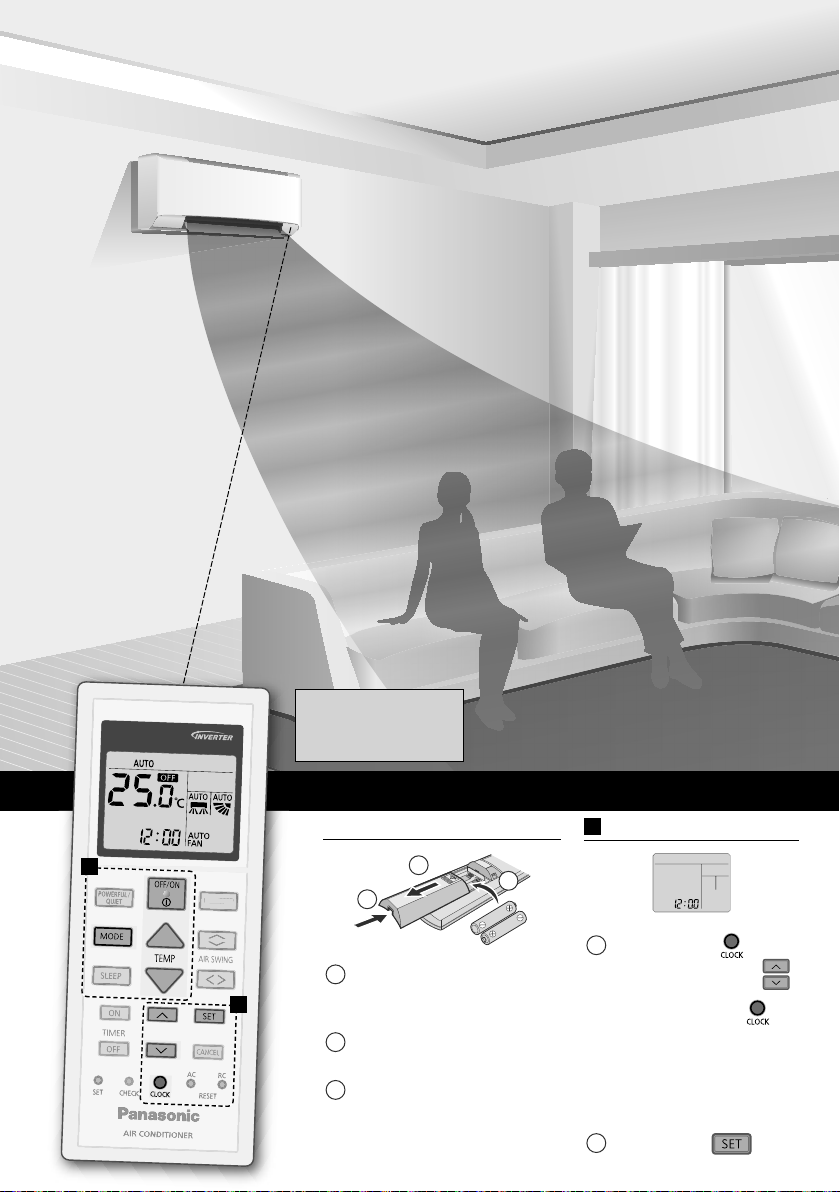
Use remote
control within 8 m
from the remote
control receiver of
the indoor unit.
* Remote control display
and functions may
vary depending on the
model.
Quick Guide
Inserting the batteries
B
Pull out the back cover
1
A
of remote control.
Insert AAA or R03
2
batteries.
Close the cover.
3
1
2
3
2
A
Clock setting
Press
1
time .
and
• Press and hold
for approximately
5 seconds to show
time in 12-hour
(am/pm) or 24 hour
indication.
Confi rm .
2
set the
Page 3
Thank you for purchasing
Panasonic Air Conditioner.
Table of contents
Safety precautions
How to use
To learn more
Cleaning instructions
Troubleshooting
Information
..........
4-15
.........................
......................
...............
............................
.....
16-17
18
19-20
21-23
68
Accessories
• Remote control
• AAA or R03 batteries × 2
• Remote control holder
• Screws for remote control
holder × 2
The illustrations in this manual are for
explanation purposes only and may differ
from the actual unit. They are subject
to change without notice for future
improvement.
English
B
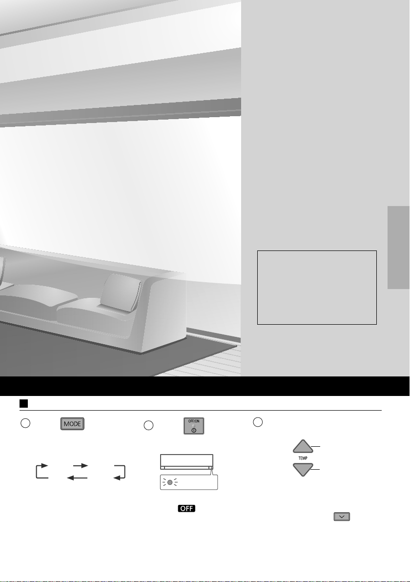
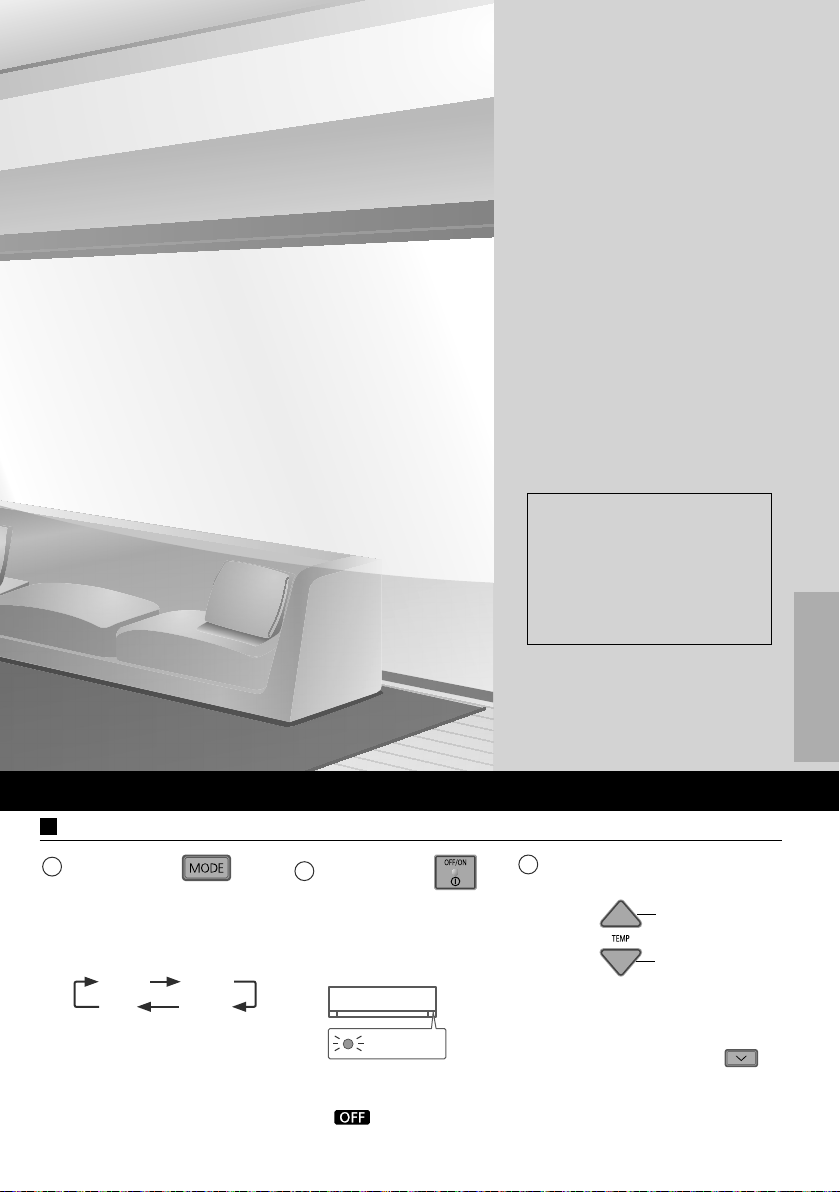
Basic operation
Press
1
to select
the desired mode.
AUTO HEAT
DRY
COOL
Press
2
to start/
stop the operation.
POWER
• Please note that
the
indication
is on display to
start the unit.
Select the desired
3
temperature.
Up
Down
Selection range:
16.0 °C ~ 30.0 °C /
60 °F ~ 86 °F.
• Press and hold
approximately 10 seconds
to switch the temperature
indication in °C or °F.
for
3
Page 4
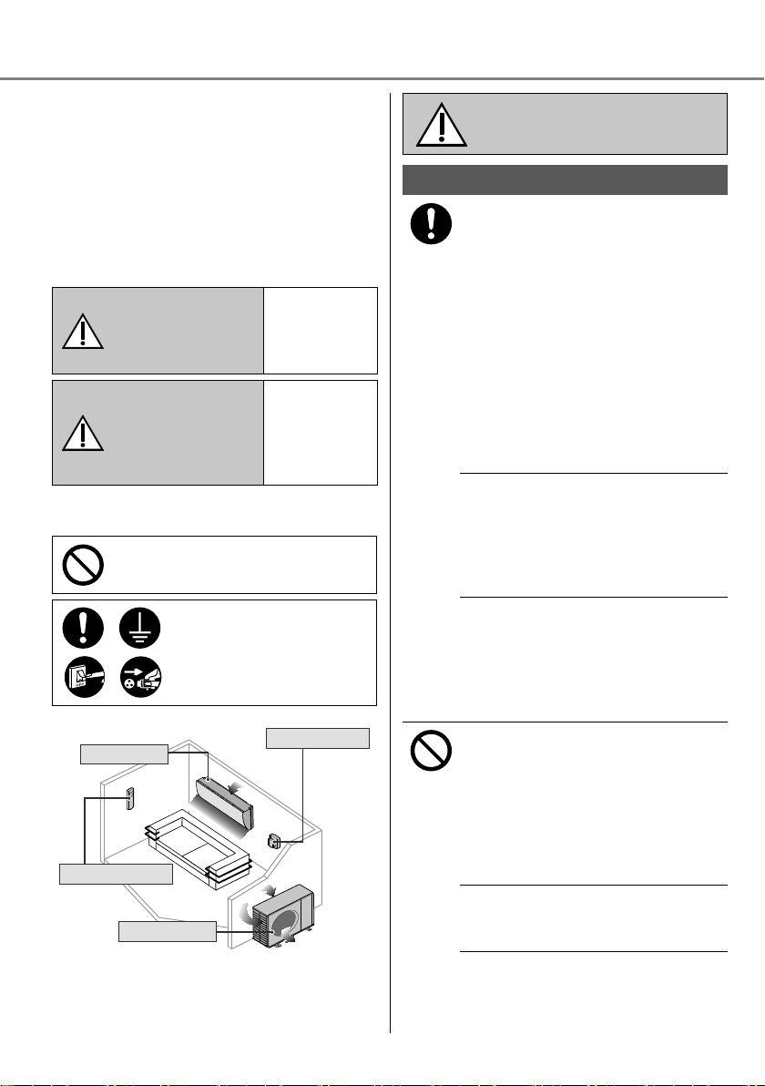
Safety precautions
Air inlet
Air inlet
Air outlet
Air outlet
To prevent personal injury, injury to others
or property damage, please comply with the
following:
Incorrect operation due to failure to follow
instructions below may cause harm or
damage, the seriousness of which is
classifi ed as below:
This appliances is not intended for
accessibility by the general public.
This sign
Air inlet
warns of
death or
serious injury.
This sign
warns of
injury or
damage to
property.
Power supply
Air outlet
WARNING
CAUTION
The instructions to be followed are classifi ed
by the following symbols:
This symbol denotes an
action that is PROHIBITED.
These symbols denote
actions COMPULSORY.
Indoor unit
Air outlet
Remote control
Outdoor unit
Air inlet
WARNING
Indoor unit and outdoor unit
This appliance can be used by
children aged from 8 years and
above and persons with reduced
physical, sensory or mental
capabilities or lack of experience
and knowledge if they have been
given supervision or instruction
concerning use of the appliance
in a safe way and understand the
hazards involved.
Children shall not play with the
appliance. Cleaning and user
maintenance shall not be made by
children without supervision.
Please consult authorised dealer or
specialist to clean the internal parts,
repair, install, remove and reinstall
the unit. Improper installation and
handling will cause leakage, electric
shock or fi re.
Confi rm with authorised dealer or
specialist on usage of any specifi ed
refrigerant type. Using refrigerant
type other than the specifi ed may
cause product damage, burst and
injury etc.
Do not use means to accelerate
the defrosting process or to clean,
other than those recommended by
manufacturer.
Any unfi t method or using
incompatible material may cause
product damage, burst and serious
injury.
Do not install the unit in a potentially
explosive or fl ammable atmosphere.
Failure to do so could result in fi re.
4
Page 5
Do not insert your fi ngers
or other objects into the air
conditioner indoor or outdoor
unit, rotating parts may cause
injury.
Do not touch the outdoor unit during
lightning, it may cause electric
shock.
Do not expose yourself directly to
cold air for a long period to avoid
excess cooling.
Do not sit or step on the unit,
you may fall down accidentally.
Remote control
Do not allow infants and small
children to play with the remote
control to prevent them from
accidentally swallowing the batteries.
Power supply
Do not use a modifi ed
cord, joint cord,
extension cord or
unspecifi ed cord to
prevent overheating
and fi re.
To prevent overheating, fi re or
electric shock:
•
Do not share the same power outlet
with other equipment.
•
Do not operate with wet hands.
•
Do not over bend the power supply
cord.
•
Do not operate or stop the unit by
inserting or pulling out the power
plug.
If the supply cord is damaged,
it must be replaced by the
manufacturer, service agent or
similarly qualifi ed persons in order to
avoid a hazard.
It is strongly recommended to be
installed with Earth Leakage Circuit
Breaker (ELCB) or Residual Current
Device (RCD) to prevent electric
shock or fi re.
To prevent overheating, fi re or
electric shock:
•
Insert the power plug properly.
•
Dust on the power plug should be
periodically wiped with a dry cloth.
Stop using the product if any
abnormality/failure occurs and
disconnect the power plug or turn off
the power switch and breaker.
(Risk of smoke/fi re/electric shock)
Examples of abnormality/failure
•
The ELCB trips frequently.
•
Burning smell is observed.
•
Abnormal noise or vibration of the
unit is observed.
•
Water leaks from the indoor unit.
•
Power cord or plug becomes
abnormally hot.
•
Fan speed cannot be controlled.
•
The unit stops running immediately
even if it is switched on for
operation.
•
The fan does not stop even if the
operation is stopped.
Contact your local dealer
immediately for maintenance/repair.
This equipment must be earthed to
prevent electrical shock or fi re.
Prevent electric shock by switching
off the power supply and unplug:
-Before cleaning or servicing,
-When extended non-use, or
-During abnormally strong
lightning activity.
EnglishSafety precautions
5
Page 6
Safety precautions
CAUTION
Indoor unit and outdoor unit
Do not wash the indoor unit with
water, benzine, thinner or scouring
powder to avoid damage or
corrosion at the unit.
Do not use for preservation of
precise equipment, food, animals,
plants, artwork or other objects. This
may cause quality deterioration, etc.
Do not use any combustible
equipment in front of the airfl ow
outlet to avoid fi re propagation.
Do not expose plants or pet directly
to airfl ow to avoid injury, etc.
Do not touch the sharp
aluminium fi n, sharp parts may
cause injury.
Do not switch ON the indoor unit
when waxing the fl oor. After waxing,
aerate the room properly before
operating the unit.
Do not install the unit in oily and
smoky areas to prevent damage to
the unit.
Do not dismantle the unit for
cleaning purpose to avoid injury.
Do not step onto an unstable bench
when cleaning the unit to avoid
injury.
Do not place a vase or water
container on the unit. Water may
enter the unit and degrade the
insulation. This may cause an
electric shock.
Do not open window or door for
long time during operation, it may
lead to ineffi cient power usage and
uncomfortable temperature changes.
Prevent water leakage by ensuring
drainage pipe is:
-Connected properly,
-Kept clear of gutters and containers,
or
-Not immersed in water
After a long period of use or use with
any combustible equipment, aerate
the room regularly.
After a long period of use, make
sure the installation rack does not
deteriorate to prevent the unit from
falling down.
Remote control
Do not use rechargeable (Ni-Cd)
batteries. It may damage the remote
control.
To prevent malfunction or damage of
the remote control:
•
Remove the batteries if the unit
is not going to be used for a long
period of time.
•
New batteries of the same type
must be inserted following the
polarity stated.
Power supply
Do not disconnect the plug by pulling
the cord to prevent electric shock.
6
Page 7

WARNING
This appliance is fi lled with
R32
(mild fl ammable refrigerant).
If the refrigerant is leaked and
exposed to an external ignition
source, there is a risk of fi re.
Indoor unit and outdoor unit
The appliance shall be installed,
and/or operated in a room with fl oor
area larger than Amin (m²) and
keep away from ignition sources,
such as heat/sparks/open fl ame
or hazardous areas such as gas
appliances, gas cooking, reticulated
gas supply systems or electric
cooking appliances, etc.(Refer to
Table A of Installation instructions
table for Amin (m²))
Be aware that refrigerant may
not contain an odour, highly
recommended to ensure suitable
fl ammable refrigerant gas detectors
are present, operating and able to
warn of a leak.
Keep any required ventilation
openings clear of obstruction.
Do not pierce or burn as the
appliance is pressurized. Do not
expose the appliance to heat, fl ame,
sparks, or other sources of ignition.
Else it may explode and cause injury
or death.
Precaution for using R32
refrigerant
The basic installation work procedures
are the same as conventional refrigerant
(R410A, R22) models.
Since the working pressure is
higher than that of refrigerant R22
models, some of the piping and
installation and service tools are
special. Especially, when replacing
a refrigerant R22 model with a
new refrigerant R32 model, always
replace the conventional piping and
fl are nuts with the R32 and R410A
piping and fl are nuts on the outdoor
unit side.
For R32 and R410A, the same fl are
nut on the outdoor unit side and pipe
can be used.
The mixing of different refrigerants
within a system is prohibited. Models
that use refrigerant R32 and R410A
have a different charging port thread
diameter to prevent erroneous
charging with refrigerant R22 and for
safety.
Therefore, check beforehand. [The
charging port thread diameter for
R32 and R410A is 1/2 inch.]
Must always ensure that foreign
matter (oil, water, etc.) does not
enter the piping. Also, when storing
the piping, securely seal the opening
by pinching, taping, etc. (Handling of
R32 is similar to R410A.)
•
Operation, maintenance, repairing
and refrigerant recovery should be
carried out by trained and certifi ed
personnel in the use of fl ammable
refrigerants and as recommended
by the manufacturer. Any personnel
conducting an operation, servicing
or maintenance on a system or
associated parts of the equipment
should be trained and certifi ed.
English
Safety precautions
7
Page 8
Safety precautions
•
Any part of refrigerating circuit
(evaporators, air coolers, AHU,
condensers or liquid receivers) or
piping should not be located in the
proximity of heat sources, open
fl ames, operating gas appliance or
an operating electric heater.
•
The user/owner or their authorised
representative shall regularly check
the alarms, mechanical ventilation
and detectors, at least once a
year, where as required by national
regulations, to ensure their correct
functioning.
•
A logbook shall be maintained. The
results of these checks shall be
recorded in the logbook.
•
In case of ventilations in occupied
spaces shall be checked to confi rm
no obstruction.
•
Before a new refrigerating system
is put into service, the person
responsible for placing the system
in operation should ensure that
trained and certifi ed operating
personnel are instructed on the
basis of the instruction manual
about the construction, supervision,
operation and maintenance of the
refrigerating system, as well as the
safety measures to be observed,
and the properties and handling of
the refrigerant used.
•
The general requirement of
trained and certifi ed personnel are
indicated as below:
a) Knowledge of legislation,
regulations and standards
relating to fl ammable
refrigerants; and,
b) Detailed knowledge of and
skills in handling fl ammable
refrigerants, personal protective
equipment, refrigerant
leakage prevention, handling
of cylinders, charging, leak
detection, recovery and
disposal; and,
c) Able to understand and to apply
in practice the requirements
in the national legislation,
regulations and Standards; and,
d) Continuously undergo regular
and further training to maintain
this expertise.
1. Installation (Space)
•
Product with fl ammable
refrigerants, shall not be installed in
an unventilated space, if that space
is smaller than Amin (m²).
•
In case of fi eld charge, the effect
on refrigerant charge caused by
the different pipe length has to be
quantifi ed, measured and labelled.
•
Must ensure the installation of pipework shall be kept to a minimum.
Avoid use dented pipe and do not
allow acute bending.
•
Must ensure that pipe-work shall be
protected from physical damage.
•
Must comply with national gas
regulations, state municipal rules
and legislation. Notify relevant
authorities in accordance with all
applicable regulations.
•
Must ensure mechanical
connections be accessible for
maintenance purposes.
•
In cases that require mechanical
ventilation, ventilation openings
shall be kept clear of obstruction.
•
When disposal of the product, do
follow to the precautions in #12 and
comply with national regulations.
Always contact to local municipal
offi ces for proper handling.
8
Page 9
2. Servicing
2-1. Service personnel
•
The system is inspected, regularly
supervised and maintained by
a trained and certifi ed service
personnel who is employed by the
person user or party responsible.
•
Ensure the actual refrigerant
charge size is in accordance with
the room size within which the
refrigerant containing parts are
installed.
•
Ensure refrigerant charge not to
leak.
•
Any qualifi ed person who is
involved with working on or
breaking into a refrigerant circuit
should hold a current valid
certifi cate from an industry-
accredited assessment authority,
which authorizes their competence
to handle refrigerants safely in
accordance with an industry
recognised assessment
specifi cation.
•
Servicing shall only be performed
as recommended by the equipment
manufacturer. Maintenance and
repair requiring the assistance of
other skilled personnel shall be
carried out under the supervision of
the person competent in the use of
fl ammable refrigerants.
•
Servicing shall be performed
only as recommended by the
manufacturer.
2-2. Work
•
Prior to beginning work on
systems containing fl ammable
refrigerants, safety checks are
necessary to ensure that the risk
of ignition is minimised. For repair
to the refrigerating system, the
precautions in #2-2 to #2-8 must
be followed before conducting
work on the system.
•
Work shall be undertaken under
a controlled procedure so as to
minimize the risk of a fl ammable
gas or vapour being present while
the work is being performed.
•
All maintenance staff and others
working in the local area shall be
instructed and supervised on the
nature of work being carried out.
•
Avoid working in confi ned spaces.
Always ensure away from source,
at least 2 meter of safety distance,
or zoning of free space area of at
least 2 meter in radius.
•
Wear appropriate protective
equipment, including respiratory
protection, as conditions warrant.
•
Ensure that the conditions within
the area have been made safe
by limit of use of any fl ammable
material. Keep all sources of
ignition and hot metal surfaces
away.
English
Safety precautions
9
Page 10
Safety precautions
2-3. Checking for presence of
refrigerant
•
The area shall be checked with an
appropriate refrigerant detector
prior to and during work, to
ensure the technician is aware of
potentially fl ammable atmospheres.
•
Ensure that the leak detection
equipment being used is suitable
for use with fl ammable refrigerants,
i.e. non sparking, adequately
sealed or intrinsically safe.
•
In case of leakage/spillage
happened, immediately ventilate
area and stay upwind and away
from spill/release.
•
In case of leakage/spillage
happened, do notify persons down
wind of the leaking/spill, isolate
immediate hazard area and keep
unauthorized personnel out.
2-4. Presence of fi re extinguisher
•
If any hot work is to be conducted
on the refrigeration equipment or
any associated parts, appropriate
fi re extinguishing equipment shall
be available at hand.
•
Have a dry powder or CO2 fi re
extinguisher adjacent to the
charging area.
2-5. No ignition sources
•
No person carrying out work in
relation to a refrigeration system
which involves exposing any pipe
work that contains or has contained
fl ammable refrigerant shall use
any sources of ignition in such a
manner that it may lead to the risk
of fi re or explosion. He/She must
not be smoking when carrying out
such work.
•
All possible ignition sources,
including cigarette smoking, should
be kept suffi ciently far away from
the site of installation, repairing,
removing and disposal, during
which fl ammable refrigerant
can possibly be released to the
surrounding space.
•
Prior to work taking place, the
area around the equipment is to
be surveyed to make sure that
there are no fl ammable hazards or
ignition risks.
•
“No Smoking” signs shall be
displayed.
2-6. Ventilated area
•
Ensure that the area is in the open
or that it is adequately ventilated
before breaking into the system or
conducting any hot work.
•
A degree of ventilation shall
continue during the period that the
work is carried out.
•
The ventilation should safely
disperse any released refrigerant
and preferably expel it externally
into the atmosphere.
10
Page 11

2-7. Checks to the refrigeration
equipment
•
Where electrical components are
being changed, they shall be fi t
for the purpose and to the correct
specifi cation.
•
At all times the manufacturer’s
maintenance and service
guidelines shall be followed.
•
If in doubt consult the
manufacturer’s technical
department for assistance.
•
The following checks shall be
applied to installations using
fl ammable refrigerants.
-
The charge size is in accordance
with the room size within which
the refrigerant containing parts
are installed.
-
The ventilation machinery and
outlets are operating adequately
and are not obstructed.
-
If an indirect refrigerating circuit is
being used, the secondary circuit
shall be checked for the presence
of refrigerant.
-
Marking to the equipment
continues to be visible and
legible. Markings and signs that
are illegible shall be corrected.
-
Refrigeration pipe or components
are installed in a position where
they are unlikely to be exposed
to any substance which may
corrode refrigerant containing
components, unless the
components are constructed of
materials which are inherently
resistant to being corroded or are
properly protected against being
so corroded.
2-8. Checks to electrical devices
•
Repair and maintenance to
electrical components shall include
initial safety checks and component
inspection procedures.
•
Initial safety checks shall include
but not limit to:-
-
That capacitors are discharged:
this shall be done in a safe
manner to avoid possibility of
sparking.
-
That there no live electrical
components and wiring are
exposed while charging,
recovering or purging the system.
-
That there is continuity of earth
bonding.
•
At all times the manufacturer’s
maintenance and service guidelines
shall be followed.
•
If in doubt consult the
English
manufacturer’s technical
department for assistance.
•
If a fault exists that could
compromise safety, then no
electrical supply shall be connected
to the circuit until it is satisfactorily
dealt with.
•
If the fault cannot be corrected
immediately but it is necessary to
continue operation, an adequate
Safety precautions
temporary solution shall be used.
•
The owner of the equipment must
be informed or reported so all
parties are advised thereinafter.
11
Page 12
Safety precautions
3. Repairs to sealed components
•
During repairs to sealed
components, all electrical supplies
shall be disconnected from the
equipment being worked upon prior
to any removal of sealed covers,
etc.
•
If it is absolutely necessary to
have an electrical supply to
equipment during servicing, then
a permanently operating form of
leak detection shall be located at
the most critical point to warn of a
potentially hazardous situation.
•
Particular attention shall be paid
to the following to ensure that by
working on electrical components,
the casing is not altered in such a
way that the level of protection is
affected.This shall include damage
to cables, excessive number of
connections, terminals not made
to original specifi cation, damage to
seals, incorrect fi tting of glands, etc.
•
Ensure that apparatus is mounted
securely.
•
Ensure that seals or sealing
materials have not degraded such
that they no longer serve the
purpose of preventing the ingress
of fl ammable atmospheres.
•
Replacement parts shall be in
accordance with the manufacturer’s
specifi cations.
NOTE: The use of silicon sealant
may inhibit the effectiveness of some
types of leak detection equipment.
Intrinsically safe components do not
have to be isolated prior to working
on them.
4. Repair to intrinsically safe
components
•
Do not apply any permanent
inductive or capacitance loads to
the circuit without ensuring that
this will not exceed the permissible
voltage and current permitted for
the equipment in use.
•
Intrinsically safe components are
the only types that can be worked
on while live in the presence of a
fl ammable atmosphere.
•
The test apparatus shall be at the
correct rating.
•
Replace components only with
parts specifi ed by the manufacturer.
Unspecifi ed parts by manufacturer
may result ignition of refrigerant in
the atmosphere from a leak.
5. Cabling
•
Check that cabling will not be
subject to wear, corrosion,
excessive pressure, vibration,
sharp edges or any other adverse
environmental effects.
•
The check shall also take into
account the effects of aging or
continual vibration from sources
such as compressors or fans.
6. Detection of fl ammable
refrigerants
•
Under no circumstances shall
potential sources of ignition be
used in the searching or detection
of refrigerant leaks.
•
A halide torch (or any other detector
using a naked fl ame) shall not be
used.
12
Page 13
7. Leak detection methods
The following leak detection
methods are deemed acceptable for
all refrigerant systems.
•
No leaks shall be detected when
using detection equipment with a
capability of 10−6 Pa·m3/s or better,
for example, a helium sniffer.
•
Electronic leak detectors may
be used to detect fl ammable
refrigerants, but the sensitivity may
not be adequate, or may need recalibration.
(Detection equipment shall be
calibrated in a refrigerant-free
area.)
•
Ensure that the detector is not a
potential source of ignition and is
suitable for the refrigerant used.
•
Leak detection equipment shall
be set at a percentage of the
LFL of the refrigerant and shall
be calibrated to the refrigerant
employed and the appropriate
percentage of gas (25 % maximum)
is confi rmed.
•
Leak detection fl uids are suitable
for use with most refrigerants but
the use of detergents containing
chlorine shall be avoided as
the chlorine may react with the
refrigerant and corrode the copper
pipe-work.
•
If a leak is suspected, all naked
fl ames shall be removed/
extinguished.
•
If a leakage of refrigerant is found
which requires brazing, all of the
refrigerant shall be recovered from
the system, or isolated (by means
of shut off valves) in a part of the
system remote from the leak.
Oxygen free nitrogen (OFN) shall
then be purged through the system
both before and during the brazing
process.
OFN = oxygen free nitrogen,
type of inert gas.
8. Removal and evacuation
•
When breaking into the refrigerant
circuit to make repairs – or for
any other purpose – conventional
procedures shall be used. However,
it is important that best practice
is followed since fl ammability is
a consideration. The following
procedure shall be adhered to:
remove refrigerant -> purge the
circuit with inert gas -> evacuate ->
purge again with inert gas -> open
the circuit by cutting or brazing
•
The refrigerant charge shall be
recovered into the correct recovery
cylinders.
•
The system shall be “fl ushed” with
OFN to render the unit safe.
•
This process may need to be
repeated several times.
•
Compressed air or oxygen shall not
English
be used for this task.
•
Flushing shall be achieved by
breaking the vacuum in the system
with OFN and continuing to fi ll until
the working pressure is achieved,
then venting to atmosphere, and
fi nally pulling down to a vacuum.
•
This process shall be repeated until
no refrigerant is within the system.
•
When the fi nal OFN charge is used,
Safety precautions
the system shall be vented down
to atmospheric pressure to enable
work to take place.
•
This operation is absolutely vital if
brazing operations on the pipe work
are to take place.
•
Ensure that the outlet for the
vacuum pump is not close to
any ignition sources and there is
ventilation available.
13
Page 14

Safety precautions
9. Charging procedures
•
In addition to conventional
charging procedures, the following
requirements shall be followed.
-
Ensure that contamination of
different refrigerants does not
occur when using charging
equipment.
-
Hoses or lines shall be as short
as possible to minimize the
amount of refrigerant contained
in them.
-
Cylinders shall be kept upright.
-
Ensure that the refrigeration
system is earthed prior to
charging the system with
refrigerant.
-
Label the system when charging
is complete (if not already).
-
Extreme care shall be taken
not to over fi ll the refrigeration
system.
•
Prior to recharging the system it
shall be pressure tested with OFN
(refer to #7).
•
The system shall be leak tested on
completion of charging but prior to
commissioning.
•
A follow up leak test shall be carried
out prior to leaving the site.
•
Electrostatic charge may
accumulate and create a hazardous
condition when charging and
discharging the refrigerant.To
avoid fi re or explosion, dissipate
static electricity during transfer by
grounding and bonding containers
and equipment before charging/
discharging.
10. Decommissioning
•
Before carrying out this procedure,
it is essential that the technician
is completely familiar with the
equipment and all its details.
•
It is recommended good practice
that all refrigerants are recovered
safely.
•
Prior to the task being carried
out, an oil and refrigerant sample
shall be taken in case analysis is
required prior to re-use of reclaimed
refrigerant.
•
It is essential that electrical power
is available before the task is
commenced.
a) Become familiar with the
equipment and its operation.
b) Isolate system electrically.
c) Before attempting the procedure
ensure that:
•
mechanical handling equipment
is available, if required, for
handling refrigerant cylinders;
•
all personal protective equipment
is available and being used
correctly;
•
the recovery process is
supervised at all times by a
competent person;
•
recovery equipment and
cylinders conform to the
appropriate standards.
d) Pump down refrigerant system,
if possible.
e) If a vacuum is not possible,
make a manifold so that
refrigerant can be removed from
various parts of the system.
f) Make sure that cylinder is
situated on the scales before
recovery takes place.
g) Start the recovery machine and
operate in accordance with
manufacturer’s instructions.
h) Do not over fi ll cylinders. (No
more than 80 % volume liquid
charge).
14
Page 15
i) Do not exceed the maximum
working pressure of the cylinder,
even temporarily.
j) When the cylinders have been
fi lled correctly and the process
completed, make sure that the
cylinders and the equipment
are removed from site promptly
and all isolation valves on the
equipment are closed off.
k) Recovered refrigerant shall
not be charged into another
refrigeration system unless it has
been cleaned and checked.
•
Electrostatic charge may accumulate
and create a hazardous condition
when charging or discharging the
refrigerant.To avoid fi re or explosion,
dissipate static electricity during
transfer by grounding and bonding
containers and equipment before
charging/discharging.
11. Labelling
•
Equipment shall be labelled stating
that it has been de-commissioned
and emptied of refrigerant.
•
The label shall be dated and signed.
•
Ensure that there are labels on the
equipment stating the equipment
contains fl ammable refrigerant.
12. Recovery
•
When removing refrigerant from
a system, either for servicing
or decommissioning, it is
recommended good practice that all
refrigerants are removed safely.
•
When transferring refrigerant
into cylinders, ensure that only
appropriate refrigerant recovery
cylinders are employed.
•
Ensure that the correct number
of cylinders for holding the total
system charge are available.
•
All cylinders to be used are
designated for the recovered
refrigerant and labelled for that
refrigerant (i.e. special cylinders for
the recovery of refrigerant).
•
Cylinders shall be complete
with pressure relief valve and
associated shut-off valves in good
working order.
•
Recovery cylinders are evacuated
and, if possible, cooled before
recovery occurs.
•
The recovery equipment shall
be in good working order with a
set of instructions concerning the
equipment that is at hand and
shall be suitable for the recovery of
fl ammable refrigerants.
•
In addition, a set of calibrated
weighing scales shall be available
and in good working order.
•
Hoses shall be complete with leakfree disconnect couplings and in
good condition.
•
Before using the recovery machine,
check that it is in satisfactory
working order, has been properly
maintained and that any associated
electrical components are sealed
to prevent ignition in the event
of a refrigerant release.Consult
manufacturer if in doubt.
•
The recovered refrigerant shall be
returned to the refrigerant supplier
in the correct recovery cylinder, and
the relevant Waste Transfer Note
arranged.
•
Do not mix refrigerants in recovery
units and especially not in cylinders.
•
If compressors or compressor oils
are to be removed, ensure that
they have been evacuated to an
acceptable level to make certain
that fl ammable refrigerant does not
remain within the lubricant.
•
The evacuation process shall be
carried out prior to returning the
compressor to the suppliers.
•
Only electric heating to the
compressor body shall be
employed to accelerate this
process.
•
When oil is drained from a system,
it shall be carried out safely.
English
Safety precautions
15
Page 16

How to use
FAN SPEEDFAN SPEED
To adjust airfl ow direction
To adjust airfl ow direction
(CS-FZ25/35/50UKE)
Indicator
CS-FZ25/35/50UKE
CS-FZ60UKE
FAN SPEED
POWER
TIMER
AIR SWING
Upper direction
• Do not adjust the fl ap by hand.
• For lateral direction, it is manually
adjustable as shown.
To adjust airfl ow direction
To adjust airfl ow direction
(CS-FZ60UKE)
Upper direction
AIR SWING
Lateral direction
• Do not adjust the fl ap by hand.
To adjust fan speed
AUTO
FAN
• For AUTO, the indoor fan speed is automatically
adjusted according to the operation mode.
• To have low noise priority operation, select the
lowest fan speed (
).
Not used
in normal
operations.
16
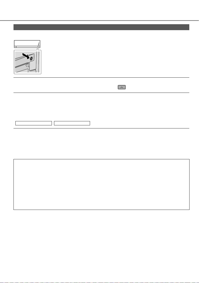
Press to restore
the remote
control to default
setting.
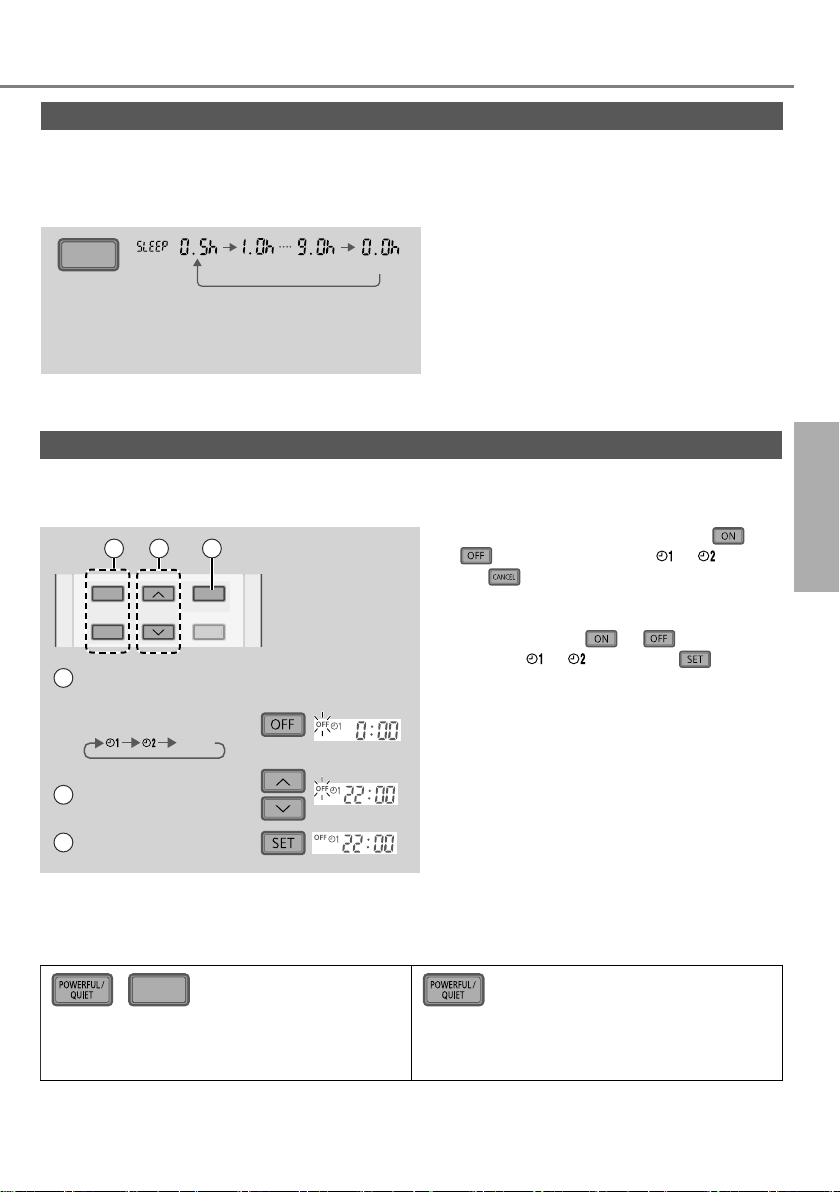
To switch between powerful/quiet
POWERFUL:
To reach the preset temperature quickly
• This operation stops automatically after 20 minutes.
QUIET:
To enjoy quiet operation
• This operation reduces airfl ow noise.
Page 17
See "To learn more..." for details.
CANCEL
To maximise comfort while sleeping
This operation provides you with a comfortable environment while sleeping. It will
automatically adjust the sleep pattern temperature during the activation period. The indoor
unit indicator will dim when this operation is activated. This is not applicable if the indicator
brightness has been manually dimmed.
•
SLEEP
(Cancel)
This operation is incorporated with the
activation timer (0.5, 1, 2, 3, 4, 5, 6, 7, 8 or 9
hours).
This operation can be set together with timer.
Sleep operation has the priority over OFF
timer.
•
This operation can be cancelled by pressing
the respective button when the sleep timer
reaches 0.0h.
To set the timer
2 sets of ON and OFF timers are available to turn ON or OFF the unit at different preset
times.
21 3
ON
TIMER
OFF
Select ON or OFF
1
timer
• Each time pressed:
Cancel
SET
CANCEL
Example:
OFF at 22:00
• To cancel ON or OFF timer, press
or
to select respective or then
press
.
• If timer is cancelled manually or due to
power failure, you can restore the timer
again by pressing
respective
or then press .
or to select
• The nearest timer setting will be displayed
and will activate in sequence.
• Timer operation is based on the clock set
in the remote control and repeats daily
once set. For clock setting, please refer to
2 Set the time
Quick Guide.
English
How to use
3 Confi rm
Note
SLEEP
,
• Can be activated in all modes and can be
cancelled by pressing the respective button
again.
• Cannot be selected at the same time.
17
Page 18
To learn more...
Operation mode
AUTO : During operation, the POWER indicator will blinks at initial.
HEAT : The POWER indicator blinks at the initial stage of this operation. Unit takes a while
COOL : Provides effi cient comfort cooling to suit your needs.
DRY : Unit operates at low fan speed to give a gentle cooling operation.
Energy saving temperature setting
Operating the unit within the recommended temperature range may save energy.
HEAT : 20.0 °C ~ 24.0 °C /
COOL: 26.0 °C ~ 28.0 °C /
Air fl ow direction
In COOL/DRY mode:
(CS-FZ25/35/50UKE)
If AUTO is set, the fl ap swings up/down automatically.
(CS-FZ60UKE)
If
AUTO is set, the fl ap swings left/right and up/down automatically.
In HEAT mode:
If AUTO is set, the horizontal fl ap is fi xed at the predetermined position. The vertical fl ap
swings left/right after the temperature rises.
Unit selects operation mode every 10 minutes according to the setting and room
temperatures.
to warm up.
• For system which HEAT mode has been locked, if operation mode other than
HEAT is selected, the indoor unit stops and the POWER indicator blinks.
68 °F ~ 75 °F.
79 °F ~ 82 °F.
Auto restart control
If power is resumed after a power failure, the operation will restart automatically after a
period of time with previous operation mode and airfl ow direction.
• This control is not applicable when TIMER is set.
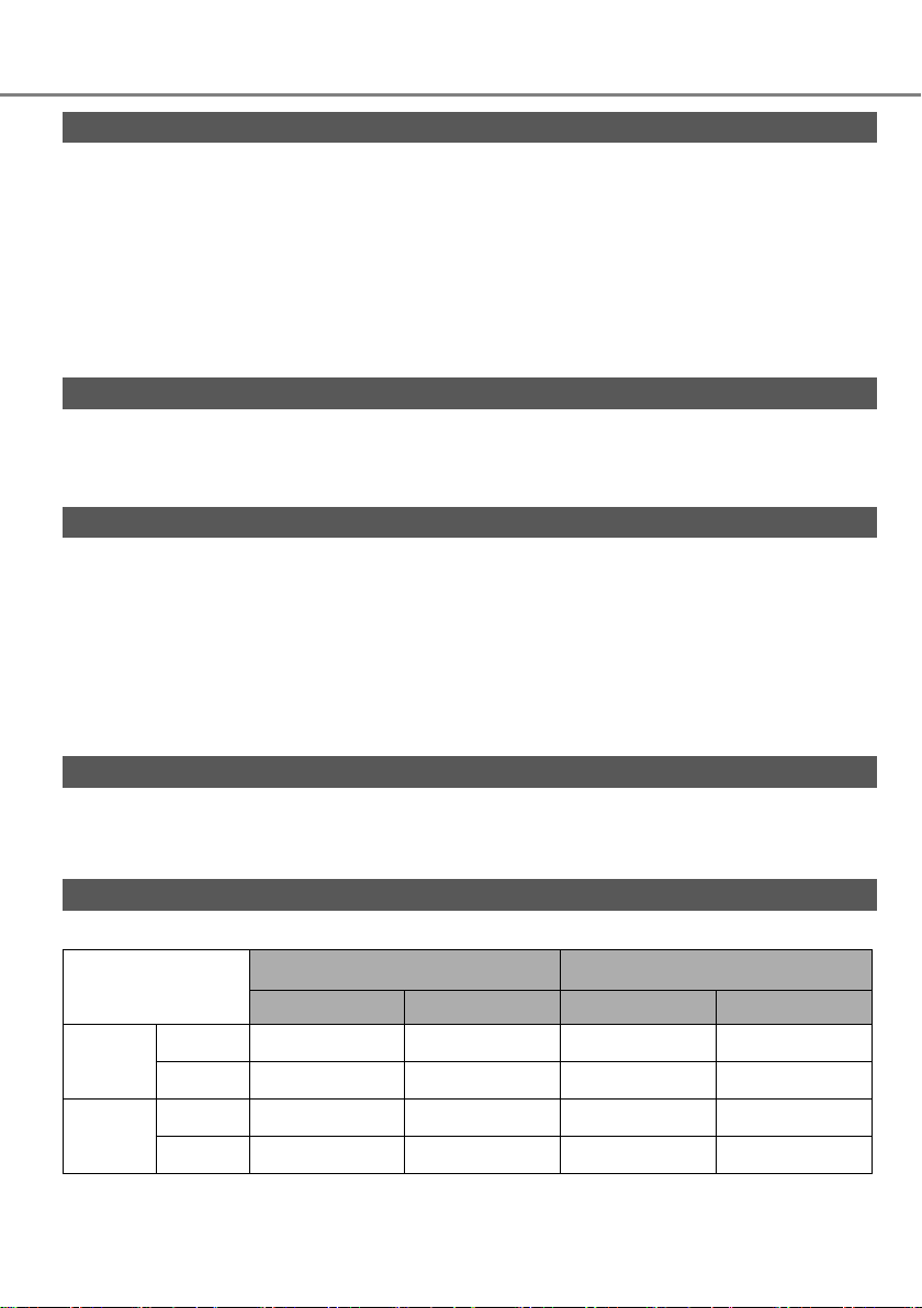
Operating conditions
Use this air conditioner in the temperature range indicated in the table.
Temperature
COOL
HEAT
DBT: Dry bulb temperature, WBT: Wet bulb temperature
°C (°F)
DBT WBT DBT WBT
Max. 32 (89.6) 23 (73.4) 43 (109.4) 26 (78.8)
Min. 16 (60.8) 11 (51.8) -10 (14.0) -
Max. 30 (86.0) - 24 (75.2) 18 (64.4)
Min. 16 (60.8) - -15 (5.0) -16 (3.2)
Indoor Outdoor
18
Page 19
Cleaning instructions
To ensure optimal performance of the unit,
cleaning has to be carried out at regular intervals.
Dirty unit may cause malfunction and you may
see error code “H 99”. Please consult authorised
dealer.
• Switch off the power supply and unplug before
cleaning.
• Do not touch the aluminium fi n, sharp parts may
cause injury.
• Do not use benzine, thinner or scouring powder.
• Use only soap (
pH 7) or neutral household
detergent.
• Do not use water hotter than 40 °C / 104 °F.
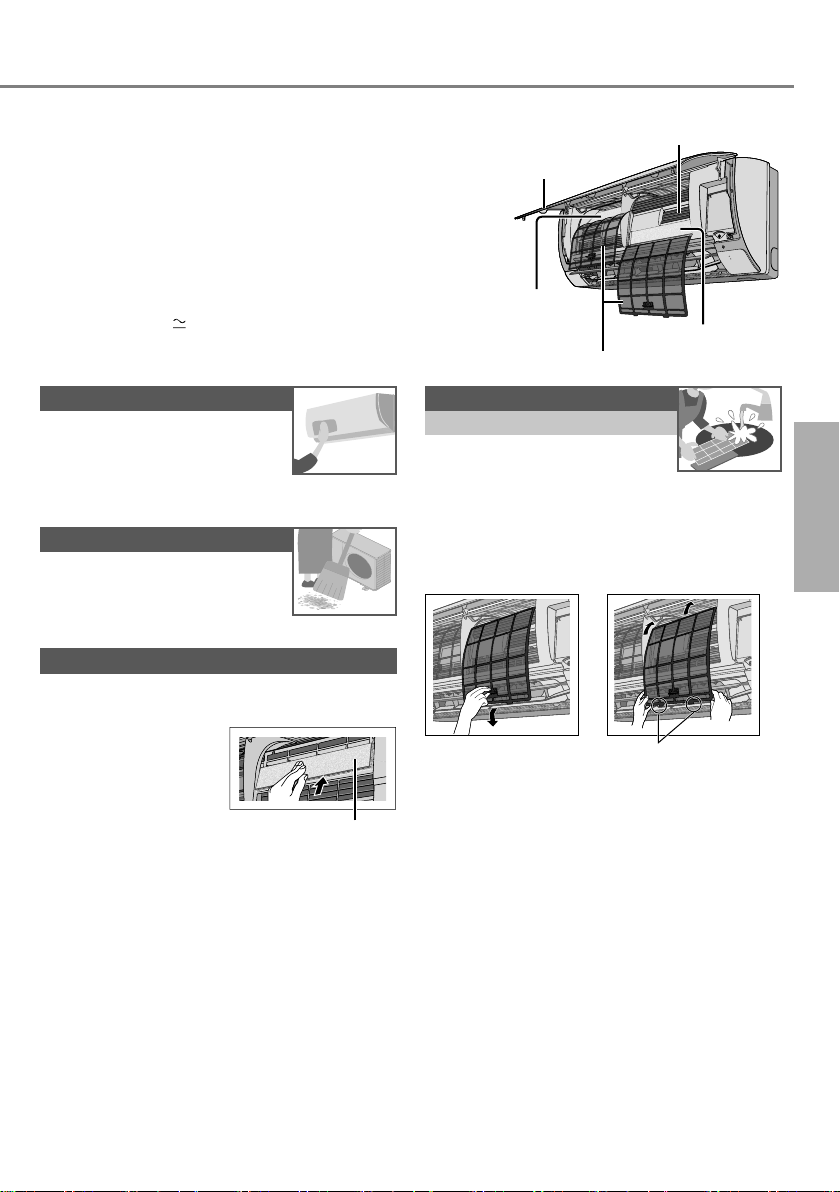
Indoor unit
Wipe the unit gently with a soft,
dry cloth.
Coils and fans should be clean
for at least every 6 months by
authorised dealer.
Outdoor unit
Clear debris that surround the
unit.
Air fi lters
Once every 2 weeks
• Wash/rinse the fi lters gently
with water to avoid damage to
the fi lter surface.
• Dry the fi lters thoroughly under shade,
away from fi re or direct sunlight.
• Replace any damaged fi lters.
Remove air fi lter Attach air fi lter
Clear any blockage from the
drain pipe.
Air Purifying Filter
• Do not wash/rinse the fi lter with water.
• Replace the fi lter every 2 years or replace
any damaged fi lter.
Part no.: CZ-SA31P
Indoor unit
Front panel
Air Purifying Filter
(CS-FZ25/35UKE)
Air fi lters
Aluminium fi n
Air Purifying Filter
(CS-FZ50/60UKE)
Insert into the unit
POWER
TIMER
EnglishTo learn more... / Cleaning instructions
Air Purifying Filter
19
Page 20
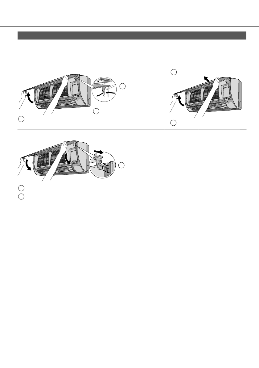
Cleaning instructions
Front panel
Wash gently and dry.
Remove the front panel
(For CS-FZ25/35/50UKE) (For CS-FZ60UKE)
Raise.
1
Close it securely
For both sides
POWER
TIMER
Pull out.
3
Slide to the
2
right or left.
Pull out.
2
Raise.
1
POWER
TIMER
POWER
TIMER
Close down.
2
Press both ends of the front panel.
3
Insert at
1
both sides.
20
Page 21
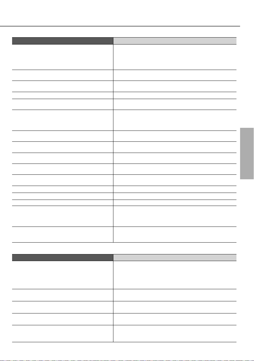
Troubleshooting
The following symptoms do not indicate malfunction.
Symptom Cause
POWER indicator blinks before the unit is
switched on.
POWER indicator blinks during HEAT mode
with no warm air supply (and fl ap is closed).
POWER indicator blinks and stops when
operate COOL/DRY mode.
TIMER indicator is always on. • The timer setting repeats daily once set.
Operation is delayed a few minutes after
restarting.
Cooling/heating capacity reduced during the
lowest fan speed setting.
Indoor fan stops occasionally during heating
operation.
Indoor fan stops occasionally during automatic
fan speed setting.
Airfl ow continues even after operation has
stopped.
The room has a peculiar odour. • This may be due to damp smell emitted by the wall,
Cracking sound during operation. • Changes of temperature caused the expansion/
Water fl owing sound during operation. • Refrigerant fl ow inside the unit.
Mist emerges from indoor unit. • Condensation effect due to cooling process.
Outdoor unit emits water/steam. • Condensation or evaporation occurs on pipes.
Dusts accumulated on the wall. • Due to air circulation or static electricity generated
Discoloration of some plastic parts. • Discoloration is subject to material types used in plastic
• This is a preliminary step in preparation for the
operation when the ON timer has been set.
When ON Timer is set, the unit may start earlier (up
to 35 minutes) before the actual set time in order to
achieve the desired temperature on time.
• The unit is in defrost mode (and AIR SWING is set to
AUTO).
• The system has locked to operate in HEAT mode only.
• The delay is a protection to the unit’s compressor.
• The low fan speed is low noise priority operation, so
cooling/heating capacity may be reduced (depending
on the condition). Increase the Fan Speed to increase
the capacity.
• To avoid unintended cooling effect.
• This helps to remove the surrounding odour.
• Extraction of remaining heat from the indoor unit
(maximum 30 seconds).
carpet, furniture or clothing.
contraction of the unit.
by the air conditioner. Some types of wall paper may
collect dusts easily (recommended to clean the area
around the air conditioner frequently).
parts, accelerated when exposed to heat, sun light, UV
light or environmental factor.
English
Check the following before calling for servicing.
Symptom Check
Operation in HEAT/COOL mode is not working
effi ciently.
Noisy during operation. • Check if the unit has been installed at an incline.
Remote control does not work.
(Display is dim or transmission signal is weak.)
The unit does not work. • Check if the circuit breaker is tripped.
The unit does not receive the signal from the
remote control.
• Set the temperature correctly.
• Close all doors and windows.
• Clean or replace the fi lters.
• Clear any obstruction at the air inlet and air outlet
vents.
• Close the front panel properly.
• Insert the batteries correctly.
• Replace weak batteries.
• Check if timers have been set.
• Make sure the receiver is not obstructed.
• Certain fl uorescent lights may interfere with signal
transmitter. Please consult authorised dealer.
Cleaning instructions / Troubleshooting
21
Page 22
Troubleshooting
When...
■ The remote control is missing or a malfunction has occurred
1.Raise the front panel.
2.Press the button once to use in AUTO mode.
3. Press and hold the button until you hear 1 beep, then release to use in
forced COOL mode.
4. Repeat step 3. Press and hold the button until you hear 2 beeps, then
release to use in forced HEAT mode.
5.Press the button again to turn off.
■ The indicators are too bright
• To dim or restore the unit’s indicator brightness, press
■ Conducting a seasonal inspection after extended non-use
• Check the remote control batteries.
• Check that there is no obstruction around the air inlet and outlet vents.
• Use Auto OFF/ON button to select COOL/HEAT operation. After 15 minutes of operation, it
is normal to have the following temperature difference between the air inlet and outlet vents:
COOL: ≥ 8 °C / 14.4 °F
■ The units are not going to be used for a long period of time
Activate HEAT mode for 2~3 hours to remove moisture left in the internal parts thoroughly to
•
prevent mould growth.
• Turn off the power supply and unplug.
• Remove the remote control batteries.
HEAT: ≥ 14 °C / 25.2 °F
and hold for 5 seconds.
NON SERVICEABLE CRITERIAS
TURN OFF THE POWER SUPPLY AND UNPLUG then please consult an authorised
dealer when in following conditions:
• Abnormal noise during operation.
• Water/foreign particles have entered the remote control.
• Water leaks from Indoor unit.
• Circuit breaker switches off frequently.
• Power cord becomes unnaturally warm.
• Switches or buttons are not functioning properly.
22
Page 23
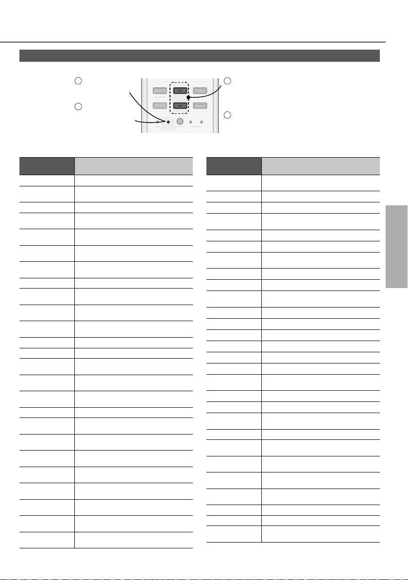
How to retrieve error codes
TIMER
S
CANCEL
ON
O
S
K
RES
C
RC
If the unit stops and the TIMER indicator blinks, use the remote control to retrieve the error code.
Press for
5 seconds
Press for 5
3
seconds to quit
checking
•
For certain errors, you may restart the unit for limited operation if there are 4 beeps when operation starts.
Diagnostic
display
Abnormality/Protection control
ON
TIMER
OFF
FF
A
SET CHECK CLOCK RESET
ET CLOC
AC
CANCEL
H 00 No memory of failure
H 11
Indoor/outdoor abnormal
communication
H 12 Indoor unit capacity unmatched
H 14
H 15
H 16
H 17
Indoor intake air temperature sensor
abnormality
Outdoor compressor temperature
sensor abnormality
Outdoor current transformer (CT)
abnormality
Outdoor suction temperature sensor
abnormality
H 19 Indoor fan motor mechanism lock
H 21
H 23
H 24
H 25
Indoor fl oat switch operation
abnormality
Indoor heat exchanger temperature
sensor 1 abnormality
Indoor heat exchanger temperature
sensor 2 abnormality
Indoor ion device abnormality
H 26 Minus ION abnormality
H 27
H 28
H 30
Outdoor air temperature sensor
abnormality
Outdoor heat exchanger temperature
sensor 1 abnormality
Outdoor discharge pipe temperature
sensor abnormality
H 31 Abnormal swimming pool sensor
H 32
H 33
H 34
H 35
H 36
H 37
H 38
H 39
Outdoor heat exchanger
temperature sensor 2 abnormality
Indoor/outdoor misconnection
abnormality
Outdoor heat sink temperature sensor
abnormality
Indoor/outdoor water adverse current
abnormality
Outdoor gas pipe temperature
sensor abnormality
Outdoor liquid pipe temperature
sensor abnormality
Indoor/outdoor mismatch
(brand code)
Abnormal indoor operating unit or
standby units
21
SET
ET
Press until you hear beep
sound, then write down the
error code
Turn the unit off and
4
RC
ET
reveal the error code to
authorised dealer
Diagnostic
display
H 41
H 50 Ventilation fan motor locked
H 51 Ventilation fan motor locked
H 52
H 58 Indoor gas sensor abnormality
H 59 Eco sensor
H 64
H 67 nanoe abnormality
H 70 Light sensor
H 71
H 72 Abnormality tank temperature sensor
H 97 Outdoor fan motor mechanism lock
H 98 Indoor high pressure protection
H 99 Indoor operating unit freeze protection
F 11 4-way valve switching abnormality
F 16 Total running current protection
F 17
F 18 Dry circuit blocked abnormality
F 87 Control box overheat protection
F 90
F 91 Refrigeration cycle abnormality
F 93
F 94
F 95
F 96
F 97 Compressor overheating protection
F 98 Total running current protection
F 99
Abnormality/Protection control
Abnormal wiring or piping
connection
Left-right limit switch fi xing
abnormality
abnormality
Outdoor high pressure sensor
abnormality
abnormality
DC cooling fan inside control board
abnormality
Indoor standby units freezing
abnormality
Power factor correction (PFC)
circuit protection
Outdoor compressor abnormal
revolution
Compressor discharge pressure
overshoot protection
Outdoor cooling high pressure
protection
Power transistor module overheating
protection
Outdoor direct current (DC) peak
detection
English
Troubleshooting
* Some error code may not be applicable to your model. Consult authorised dealer for clarifi cation.
23
Page 24
Fournit un confort maximum avec des méthodes
FAN SPEED
FAN SPEED
d’économie d’énergie optimales.
Utilisez la
télécommande
dans les 8 m du
récepteur de la
télécommande de
l’unité intérieure.
24
* L’affi chage et les
fonctions de la
télécommande peuvent
varier selon le modèle.
Guide Rapide
Insertion des piles
B
Retirez le couvercle
1
A
arrière de la
télécommande.
Placez des piles AAA ou
2
R03.
Fermez le couvercle.
3
1
2
3
A
Réglage de l’horloge
Appuyez sur et
1
réglez l’heure time
•
Maintenez la touche
enfoncée pendant environ
5 secondes pour passer du
mode d’affi chage 12 heures
(am/pm) ou au mode 24
heures et inversement.
Confi rmez
2
.
.
Page 25
Nous vous remercions d’avoir
porté votre choix sur un climatiseur
Panasonic.
Table des matières
Consignes de sécurité
Consignes d’utilisation
Pour en savoir plus
Instructions de nettoyage
Dépannage
Informations
......................................
...............................................
......
26-37
.....
38-39
..........................
.........
40
41-42
43-45
69
Accessoires
•
Télécommande
•
Piles AAA ou R03 × 2
•
Support de la télécommande
•
Vis pour le support de la
télécommande × 2
Les illustrations de ce mode d’emploi
sont fournies à titre d’exemple
uniquement et peuvent présenter des
différences par rapport à l’appareil
proprement dit. Celui-ci peut être modifi é
sans préavis à des fi ns d’amélioration.
Français
B
Fonctionnement de base
Appuyez sur
1
pour sélectionner le
mode souhaité.
AUTO HEAT
DRY
COOL
Appuyez sur
2
pour mettre le
fonctionnement en
marche/arrêt.
POWER
• Veuillez noter
que l’indication
se trouve sur
l’affi cheur pour
démarrer l’unité.
Sélectionnez la
3
température souhaitée.
Haut
Bas
Plage de sélection:
16.0 °C ~ 30.0 °C /
60 °F ~ 86 °F.
• Maintenez la touche
enfoncée pendant environ
10 secondes passer
l’indication de température
en °C ou en °F.
25
Page 26

Consignes de sécurité
Entrée d’air
Entrée d’air
Sortie d’air
Sortie d’air
Pour éviter des blessures corporelles sur vousmême et sur les autres ou des dégâts matériels,
respectez les instructions ci-dessous :
Tout dysfonctionnement dû au non-respect des
instructions peut occasionner des nuisances ou
des dégâts dont la gravité est classée comme
décrit ci-après :
Ces appareils ne sont pas conçus pour être
accessibles du grand public.
Ce symbole signale
la présence d’un
AVERTISSEMENT
ATTENTION
Les instructions à respecter sont classées
d’après les symboles suivants :
Ce symbole désigne une
action INTERDITE.
Ces symboles désignent des
actions OBLIGATOIRES.
Unité
intérieure
Sortie d’air
Télécommande
Unité
extérieure
danger pouvant
provoquer des
blessures graves
ou mortelles.
Ce symbole signale
la présence d’un
danger pouvant
provoquer
des blessures
corporelles ou des
dégâts matériels.
Alimentation électrique
Entrée d’air
Entrée d’air
Sortie d’air
AVERTISSEMENT
Unité intérieure et unité extérieure
Cet appareil peut être utilisé par des
enfants âgés de 8 ans et plus et par
des personnes ayant des capacités
physiques, sensorielles ou mentales
réduites, ou dénuées d’expérience
et de connaissances si elles ont été
formées et encadrées pour l’utilisation
de cet appareil en toute sécurité et
comprennent bien les dangers auxquels
ils s’exposent.
Les enfants ne doivent pas jouer avec
l’appareil. Le nettoyage et l’entretien par
l’utilisateur ne doivent pas être effectués
par des enfants sans surveillance.
Veuillez consulter un revendeur agréé
ou un spécialiste pour le nettoyage des
pièces internes et pour la réparation,
l’installation, le retrait et la réinstallation
de l’unité. Une installation et une
manipulation incorrectes pourraient
occasionner des fuites, un choc
électrique ou un incendie.
Validez auprès du revendeur agréé ou
du spécialiste l’usage de tout type de
réfrigérant spécifi é. L’utilisation d’un
type de réfrigérant autre que le type
spécifi é peut endommager le produit ou
provoquer des explosions, des brûlures,
etc.
N'utilisez pas de moyens d'accélérer le
processus de dégivrage ou de nettoyer,
autres que ceux qui sont conseillés par
le fabricant.
Toute méthode inappropriée ou
utilisation de matériel incompatible peut
occasionner une détérioration du produit,
une explosion et de graves blessures.
N’installez pas l’appareil dans une
atmosphère potentiellement explosive ou
infl ammable.
Sinon, il y a un risque d’incendie.
26
Page 27
N’insérez jamais vos doigts ou
des objets dans l’unité intérieure
ou extérieure du climatiseur, les
parties tournantes peuvent causer
des blessures.
Ne touchez pas l’unité extérieure
au cours d’un orage, cela pourrait
provoquer un choc électrique.
Ne vous exposez pas directement à de
l’air froid pendant une période prolongée
afi n d’éviter un refroidissement excessif.
Ne vous asseyez pas et
ne montez pas sur l’unité,
vous risquez de tomber
accidentellement.
Télécommande
Maintenez la télécommande hors de
portée des bébés et des enfants pour
éviter qu’ils n’avalent accidentellement
les piles.
Alimentation
N’utilisez pas de cordon
modifi é, de raccords, de
rallonge ou de cordon non
spécifi é afi n d’éviter une
surchauffe et un incendie.
Pour éviter une surchauffe, un incendie
ou un choc électrique :
•
Ne partagez pas la prise d’alimentation
avec un autre appareil.
•
N’utilisez pas l’unité avec des mains
mouillées.
•
Ne pas plier excessivement la fi che
électrique.
•
Ne pas opérer ou arrêter l’unité en
insérant ou en tirant sur la fi che
électrique.
Si le cordon d’alimentation est
endommagé, il doit être remplacé par
le fabriquant, par un de ses techniciens
ou par une personne qui possède des
qualifi cations équivalentes afi n d’éviter
tout risque.
Il est fortement conseillé d’installer
un disjoncteur-détecteur de fuite à la
terre (DDFT) ou un dispositif à courant
résiduel (DCR) afi n d’éviter un choc
électrique ou un incendie.
Pour éviter une surchauffe, un incendie
ou un choc électrique :
•
Insérez la fi che d’alimentation
correctement.
•
Il faut régulièrement essuyer la poussière
sur la fi che d’alimentation à l’aide d’un
chiffon sec.
Cesser d’utiliser le produit lorsqu’une
anomalie ou défaillance quelconque
se produit et débrancher la fi che
d’alimentation ou mettre hors tension
l’interrupteur et le disjoncteur.
(Risque de fumée / feu / choc électrique)
Exemples d’anomalie ou défaillance
•
L’ELCB se déclenche fréquemment.
•
Odeur de brûlé est observée.
•
Un bruit ou des vibrations anormales de
l’unité sont observés.
•
Fuite d’eau de l’unité intérieure.
•
Le cordon d’alimentation ou la prise
deviennent anormalement chaud.
•
La vitesse du ventilateur ne peut pas
être contrôlée.
•
L’unité s’arrête de fonctionner
immédiatement même si elle est
activée pour opérer.
•
Le ventilateur ne s’arrête pas même si
l’opération est arrêtée.
Contacter immédiatement votre
revendeur local pour l’entretien /
réparation.
Cet équipement doit être raccordé à la
terre afi n d’éviter un choc électrique ou
un incendie.
Prévenez les chocs électriques en
coupant l’alimentation et en débranchant
l’unité :
- Avant le nettoyage ou l’entretien.
- En cas de non utilisation prolongée, ou
- En période d’activité orageuse
anormalement forte.
Français Consignes de sécurité
27
Page 28

Consignes de sécurité
ATTENTION
Unité intérieure et unité extérieure
Afi n d’éviter des dommages ou de la
corrosion sur l’unité, ne nettoyez pas
l’unité intérieure avec de l’eau, du
benzène, du solvant ou de la poudre à
récurer.
N’utilisez pas l’unité pour conserver des
appareils de précision, des aliments,
des plantes, des œuvres d’art ou autres
objets. Cela pourrait entraîner une
détérioration de la qualité, etc.
N’utiliser pas d’appareil à combustibles
dans la direction du fl ux d’air afi n d’éviter
toute propagation du feu.
N’exposez pas des plantes ou des
animaux de compagnie directement au
fl ux d’air pour éviter des blessures, etc.
Ne touchez pas l’ailette pointue
d’aluminium, les parties pointues
peuvent causer des dommages.
Ne mettez pas l’unité intérieure sous
tension lorsque vous cirez le sol. Après
le cirage, aérez suffi samment la pièce
avant de faire fonctionner l’unité.
Afi n d’éviter d’endommager l’unité, ne
l’installez pas dans des zones grasses et
enfumées.
Afi n d’éviter des blessures, ne démontez
pas l’unité pour la nettoyer.
Afi n d’éviter des blessures, ne marchez
pas sur un banc instable lors du
nettoyage de l’unité.
Ne placez pas de vas ou de récipient
d’eau sur l’unité. De l’eau peut pénétrer
à l’intérieur de l’unité et dégrader
l’isolation. Cela pourrait entraîner un
choc électrique.
N'ouvrez pas de fenêtre ou de porte
pendant longtemps lorsque l'appareil est
en marche, car cela peut compromettre
la consommation électrique et
provoquer des variations de température
inconfortables.
Prévenez les fuites d’eau en vous
assurant que le tuyau de vidange est :
- Correctement raccordé,
- Dégagé de toute gouttière et récipient, ou
- Non immergé dans l’eau
Après une longue période d’utilisation
ou après une utilisation avec un appareil
à combustibles, aérez régulièrement la
pièce.
Après une longue période d’utilisation,
assurez-vous que le support
d’installation n’est pas détérioré afi n
d’éviter une chute de l’unité.
Télécommande
N’utilisez pas de piles rechargeables
(Ni-Cd). Cela pourrait endommager la
télécommande.
Pour éviter tout dysfonctionnement ou
dommages à la télécommande :
•
Retirez les piles si vous envisagez de
ne pas utiliser l’appareil pendant une
période prolongée.
•
De nouvelles piles du même type
doivent être insérées en respectant la
polarité indiquée.
Alimentation
Ne débranchez pas la fi che en tirant sur
le cordon d’éviter un choc électrique.
28
Page 29

AVERTISSEMENT
L'appareil est rempli de R32
(réfrigérant infl ammable doux).
Il existe un risque d'incendie
en cas de fuite du réfrigérant
et d'exposition à une source
d'infl ammation externe.
Unité intérieure et unité extérieure
L'appareil doit être installé et/ou utilisé
dans une pièce dont la surface au
sol dépasse Amin (m²) et maintenu à
distance des sources d'infl ammation,
comme la chaleur/les étincelles/
les fl ammes nues, ou des zones
dangereuses, comme les appareils à
gaz, les appareils de cuisson au gaz, les
systèmes d'approvisionnement en gaz
ou les appareils de cuisson électrique,
etc. (Référez-vous au Tableau A du
tableau des consignes d'installation pour
Amin (m²))
Sachez que le réfrigérant peut ne
pas comporter d'odeur. Il est très
recommandé de s'assurer que
les détecteurs appropriés de gaz
réfrigérants infl ammables sont utilisés,
fonctionnent bien et peuvent alerter en
cas de fuite.
Dégagez de toute obstruction toutes les
ouvertures de ventilation requises.
N'utilisez pas l'appareil pour percer ni
brûler pendant qu'il est sous pression.
N'exposez pas l'appareil à la chaleur,
aux fl ammes, aux étincelles ou à
d'autres sources d'infl ammation. Sinon
il peut exploser et provoquer des
blessures ou la mort.
Précautions pour l’utilisation
du réfrigérant R32
Les procédures d'installation de base sont les
mêmes que pour les modèles à réfrigérant
classiques (R410A, R22).
La pression de fonctionnement étant
supérieure à celle des modèles
à réfrigérant R22, certaines des
tuyauteries et certains outils d'installation
et d'entretien sont spécifi ques. En
particulier, lorsque vous remplacez
un modèle à réfrigérant R22 par un
nouveau modèle à réfrigérant R32,
remplacez toujours la tuyauterie
classique et les écrous d'évasement
avec la tuyauterie et les écrous
d'évasement R32 et R410A côté
extérieur de l'unité.
Pour le R32 et le R410A, le même écrou
d'évasement peut être utilisé sur le côté
et le tuyau de l'unité extérieure.
Il est interdit de mélanger des
réfrigérants différents dans un même
système. Les modèles qui utilisent le
réfrigérant R32 et R410A ont différents
diamètres de fi letage des ports de
charge, pour éviter les charges erronées
avec du réfrigérant R22 et pour la
sécurité.
Vérifi ez donc en amont. [Le diamètre de
fi letage du port de charge pour R32 et
R410A est de 12,7 mm (1/2 pouces).]
Vous devez toujours vous assurer que
les matières étrangères (huile, eau, etc.)
n’entrent pas dans le tuyau. Lorsque
vous stockerez la tuyauterie, scellez bien
l'ouverture en pinçant, tapant, etc. (La
manipulation du R32 est similaire à celle
du R410A.)
•
Le fonctionnement, la maintenance,
la réparation et la récupération du
réfrigérant doivent être effectués par
du personnel qualifi é et certifi é en ce
qui concerne l’utilisation de réfrigérants
infl ammables et conformément aux
recommandations du fabricant. Tout
personnel qui effectue une opération,
un entretien ou une maintenance sur
un système ou des pièces associées de
l’équipement doit être formé et certifi é.
Français Consignes de sécurité
29
Page 30

Consignes de sécurité
30
•
Aucune partie du circuit de réfrigération
(évaporateurs, refroidisseurs d’air, AHU,
condensateurs ou réservoirs de liquide)
ou de la tuyauterie ne doit être située
à proximité de sources de chaleur, de
fl ammes ouvertes, d’un appareil à gaz
en fonctionnement ou d’un chauffage
électrique en fonctionnement.
•
L’utilisateur/propriétaire ou son
représentant autorisé doit vérifi er
régulièrement les alarmes, la ventilation
mécanique et les détecteurs, au
moins une fois par an, lorsque
les réglementations nationales
l’exigent, afi n d’en garantir le bon
fonctionnement.
•
Un journal de bord doit être tenu à jour.
Les résultats de ces contrôles doivent
être consignés dans le journal de bord.
•
En cas de ventilation dans des locaux
occupés, il convient de vérifi er qu’il n’y
a pas d’obstruction.
•
Avant la mise en service d’un nouveau
système de réfrigérant, la personne
responsable de la mise en service doit
s’assurer que le personnel opérateur
formé et certifi é est informé, sur la
base du manuel d’instructions, de
la construction, de la surveillance,
du fonctionnement et de l’entretien
du système de réfrigérant, ainsi que
des mesures de sécurité à respecter
ainsi que des propriétés et de la
manipulation du réfrigérant utilisé.
•
Les exigences générales relatives
au personnel formé et certifi é sont
indiquées ci-dessous :
a) Connaissance de la législation,
des règlements et des normes
concernant les réfrigérants
infl ammables ; et,
b) Connaissances et compétences
approfondies en matière de
manipulation des réfrigérants
infl ammables, d’équipement
de protection individuelle,
de prévention des fuites de
frigorigènes, de manutention des
bouteilles, de chargement, de
détection, de récupération et de
mise au rebut ; et,
c) Capacité de comprendre et
d’appliquer dans la pratique les
exigences de la législation, des
réglementations et des normes
nationales ; et,
d) Suivi d’une formation de base et
approfondie et afi n de maintenir
cette expertise.
1. Installation (Espace)
•
Le produit contenant des réfrigérants
infl ammables ne doit pas être installé
dans un local non ventilé si cet espace
est inférieur à Amin (m²).
•
En cas de charge sur site, l’effet sur la
charge de réfrigérant dû aux différentes
longueurs de tuyau doit être quantifi é,
mesuré et étiqueté.
•
Assurez-vous que la tuyauterie est
installée à sa longueur minimum. Évitez
d'utiliser des tuyaux cabossés et évitez
les courbures importantes.
•
Assurez-vous que la tuyauterie
est protégée de toute détérioration
physique.
•
Assurez-vous de vous conformer aux
réglementations nationales sur le gaz,
aux règles et à la législation d'état
et municipale. Notifi ez les autorités
compétentes conformément aux
réglementations en vigueur.
•
Assurez-vous que les raccords
mécaniques sont accessibles pour la
maintenance.
•
Dans les cas nécessitant une
ventilation mécanique, les ouvertures
de ventilation doivent être dégagées de
toute obstruction.
•
Lors de la mise au rebut du
produit, suivez les précautions du
paragraphe 12 et conformez-vous aux
réglementations nationales.
Contactez toujours les bureaux locaux
et municipaux pour une manipulation
correcte.
Page 31

2. Entretien
2-1. Personnel de service
•
Le système est inspecté, régulièrement
surveillé et entretenu par un personnel
de maintenance formé et certifi é,
employé par la personne responsable
ou par l’utilisateur.
•
Assurez-vous que la quantité de charge
réelle de réfrigérant correspond à la
taille de la pièce dans laquelle sont
installées les pièces contenant du
réfrigérant.
•
Assurez-vous que la charge de
réfrigérant ne fuit pas.
•
Toute personne qualifi ée travaillant ou
pénétrant dans un circuit de réfrigérant
doit détenir un certifi cat en cours
de validité remis par une autorité
d'évaluation agréé par l'industrie, qui
valide sa compétence à manipuler
les réfrigérants en toute sécurité
conformément à une spécifi cation
d'évaluation reconnue par l'industrie.
•
L'entretien doit uniquement être
effectué conformément aux
recommandations du fabricant de
l'équipement. Toute maintenance et
réparation nécessitant l'aide d'autres
personnes qualifi ées doit être effectuée
sous la supervision de la personne
compétente dans l'utilisation des
réfrigérants infl ammables.
•
L'entretien doit uniquement être
effectué conformément aux
recommandations du fabricant.
2-2. Travail
•
Avant de commencer des travaux sur
les systèmes contenant des réfrigérants
infl ammables, des contrôles de sécurité
sont obligatoires pour s'assurer que
le risque d'infl ammation est minimisé.
Pour les réparations sur le système
de réfrigérant, les précautions des
paragraphes 2-2 à 2-8 doivent être
respectées avant d'entreprendre tout
travail sur le système.
•
Le travail doit être entrepris dans
le cadre d'une procédure contrôlée
de manière à minimiser le risque
de présence de gaz ou de vapeurs
infl ammables pendant la réalisation du
travail.
•
Tous les techniciens de maintenance
et autres personnels travaillant dans la
zone locale doivent être conseillés et
supervisés sur la nature du travail en
cours.
•
Évitez de travailler dans des espaces
confi nés. Assurez-vous toujours que
la distance de sécurité est d’au moins
2 mètres ou que la zone d’espace libre
est d’au moins 2 mètres de rayon.
•
Portez un équipement de protection
individuelle approprié, y compris une
protection respiratoire si la situation le
justifi e.
•
Assurez-vous que les conditions au
sein de la zone ont été sécurisées
en limitant l'usage de toute matière
infl ammable. Tenez toutes les sources
d'infl ammation et surfaces en métal
chaudes à distance.
Consignes de sécurité
Français
31
Page 32
Consignes de sécurité
2-3. Vérifi cation de la présence de
réfrigérant
•
La zone doit être vérifi ée à l'aide d'un
détecteur de réfrigérant approprié
avant et pendant les travaux, afi n
de s'assurer que le technicien soit
informé de la présence d'atmosphères
potentiellement infl ammables.
•
Assurez-vous que l'équipement de
détection des fuites utilisé est adapté
à une utilisation avec des réfrigérants
infl ammables, c'est-à-dire sans
étincelle, hermétiquement scellé ou
intrinsèquement sécurisé.
•
En cas de fuite/déversement, ventilez
immédiatement la zone et restez en
amont et à distance du déversement/
décharge.
•
En cas de fuite/déversement,
avertissez les personnes se trouvant
en aval de la fuite/déversement, isolez
la zone des dangers immédiats et ne
laissez pas entrer le personnel non
autorisé.
2-4. Présence d'un extincteur
•
Si un quelconque travail à chaud
doit être réalisé sur l'équipement de
réfrigération ou toute pièce associée,
un équipement d'extinction d'incendie
approprié doit être à disposition et à
portée de main.
•
Un extincteur d'incendie à poudre
sèche ou CO
côté de la zone de charge.
doit être disponible à
2
2-5. Aucune source d'infl ammation
•
Personne, pendant la réalisation d'une
tâche en lien avec un système de
réfrigération impliquant une exposition
à toute tuyauterie contenant ou ayant
contenu du réfrigérant infl ammable, ne
doit utiliser de sources d'infl ammation
quelconques afi n d'éviter tout risque
d'incendie ou d'explosion. Il ou elle ne
doit pas fumer pendant la réalisation
d'une telle tâche.
•
Toutes les sources d'infl ammation
possibles, y compris le fait de
fumer une cigarette, doivent rester
suffi samment éloignées du site
d'installation, de réparation, de retrait
et de mise au rebut. Du réfrigérant
infl ammable pourrait en effet être
déchargé dans l'espace environnant
pendant ces activités.
•
Avant le début des travaux, la zone
environnant l'équipement doit être
surveillée pour s'assurer de l'absence
de matières infl ammables ou de risques
d'infl ammation.
•
Des panneaux « Interdiction de fumer »
doivent être affi chés.
2-6. Zone ventilée
•
Assurez-vous que la zone est ouverte
ou suffi samment ventilée avant de
pénétrer dans le système ou de réaliser
tout travail à chaud.
•
Un certain degré de ventilation doit
perdurer pendant la période de
réalisation des travaux.
•
La ventilation doit disperser en toute
sécurité tout réfrigérant libéré et de
préférence le rejeter dans l'atmosphère.
32
Page 33
2-7. Contrôles sur l'équipement de
réfrigération
•
Si des composants électriques doivent
être changés, ils doivent être adaptés à
l'usage prévu et présenter les bonnes
caractéristiques.
•
Les directives de maintenance et
d'entretien du fabricant doivent être
respectées à tout moment.
•
En cas de doute, demandez une
assistance au service technique du
fabricant.
•
Les contrôles suivants doivent être
appliqués aux installations utilisant des
réfrigérants infl ammables.
-
La quantité de charge doit
correspondre à la taille de la pièce
dans laquelle sont installées les
pièces contenant du réfrigérant.
-
Les mécanismes et sorties de
ventilation fonctionnent correctement
et ne sont pas obstrués.
-
Si un circuit de réfrigération indirect
est utilisé, la présence de réfrigérant
dans le circuit secondaire doit être
vérifi ée.
-
Le marquage de l'équipement
doit rester visible et lisible. Les
marquages et panneaux illisibles
doivent être corrigés.
-
Le tuyau ou les composants de
réfrigération sont installés de manière
à ne pas risquer d'être exposés à
toute substance susceptible de faire
rouiller les composants contenant du
réfrigérant, sauf s'ils sont composés
de matériaux résistants par nature
à la corrosion ou correctement
protégés contre la corrosion.
2-8. Contrôles sur les dispositifs
électriques
•
La réparation ou la maintenance des
composants électriques doit inclure
les contrôles de sécurité initiaux
et les procédures d'inspection des
composants.
•
Dans le cadre des contrôles de sécurité
initiaux, il convient de vérifi er, sans s'y
limiter :-
-
Que les condensateurs sont
déchargés : ceci doit se faire de
manière sécurisée pour éviter le
risque d'étincelles.
-
Qu'aucun composant ou câble
électrique n'est exposé pendant la
charge, la récupération ou la purge
du système.
-
Que le raccordement à la terre se fait
en continu.
•
Les directives de maintenance et
d'entretien du fabricant doivent être
respectées à tout moment.
•
En cas de doute, demandez une
assistance au service technique du
fabricant.
•
En cas de défaut susceptible de
compromettre la sécurité, aucune
alimentation électrique ne doit être
raccordée au circuit avant sa complète
résolution.
•
Si le défaut ne peut pas être
immédiatement corrigé mais qu'il
est nécessaire de poursuivre le
fonctionnement, une solution
temporaire adéquate doit être utilisée.
•
Le propriétaire de l'équipement doit être
informé ou signalé de manière à ce que
toutes les parties soient notifi ées.
Consignes de sécurité
Français
33
Page 34
Consignes de sécurité
3. Réparation des composants
étanches
•
Pendant la réparation des composants
étanches, toutes les alimentations
électriques doivent être déconnectées
de l'équipement faisant l'objet de
l'intervention avant tout retrait de
couvercles étanches, etc.
•
S'il est absolument nécessaire
d'alimenter électriquement l'équipement
pendant l'entretien, un système de
détection des fuites fonctionnant en
permanence devra être situé au point
le plus critique afi n de signaler toute
situation potentiellement dangereuse.
•
Les éléments suivants doivent faire
l'objet d'une attention particulière,
pour s'assurer qu'en travaillant sur
les composants électriques, le boîtier
n'est pas altéré de manière à affecter
le niveau de protection.Ceci devra
inclure les dommages sur les câbles,
le nombre excessif de raccordements,
les bornes ne respectant pas les
caractéristiques d'origine, une
mauvaise étanchéité, le raccord
incorrect des presse-étoupes, etc.
•
Assurez-vous que l'appareil est monté
solidement.
•
Assurez-vous que les joints ou
l'étanchéité ne présentent pas de
dégradation de nature à ne plus servir
l'objectif de prévention de l'entrée
d'atmosphères infl ammables.
•
Les pièces de rechange doivent être
conformes aux spécifi cations du
fabricant.
REMARQUE : L'utilisation de joints
en silicone peut inhiber l'effi cacité
de certains types d'équipements de
détection des fuites.
Les composants intrinsèquement
sécurisés n'ont pas besoin d'être isolés
avant intervention.
4. Réparation des composants
intrinsèquement sécurisés
•
N'appliquez aucune charge inductive ou
capacitive permanente au circuit sans
vous assurer que cela ne dépassera
pas la tension admissible et le courant
autorisé pour l'équipement en cours
d'utilisation.
•
Les composants intrinsèquement
sécurisés sont les seuls sur lesquels il
est possible de travailler sous tension
en présence d'une atmosphère
infl ammable.
•
La valeur de l'appareil de test doit être
correcte.
•
Remplacez uniquement les
composants dont les pièces sont
spécifi ées par le fabricant. Les pièces
non spécifi ées par le fabricant peuvent
entraîner l'infl ammation du réfrigérant
dans l'atmosphère à partir d'une fuite.
5. Câblage
•
Vérifi ez que le câblage n'est pas
soumis à l'usure, à la corrosion, à une
pression excessive, aux vibrations, à
des bords coupants ou tout autre effet
environnemental négatif.
•
Le contrôle doit également prendre en
compte les effets du vieillissement ou
des vibrations continues provenant de
sources telles que compresseurs ou
ventilateurs.
6. Détection des réfrigérants
infl ammables
•
En aucun cas les sources potentielles
d'infl ammation ne doivent être utilisées
pour la recherche ou la détection de
fuites de réfrigérant.
•
N'utilisez pas de torche haloïde (ou tout
autre détecteur utilisant une fl amme
nue).
34
Page 35
7. Méthodes de détection des fuites
Les méthodes de détection des fuites
suivantes sont jugées acceptables pour
tous les systèmes de réfrigérant.
•
Aucune fuite ne doit être détectée lors
de l’utilisation d’un équipement de
détection ayant une capacité de 10
3
Pa·m
/s ou mieux, par exemple un
−6
renifl eur d’hélium.
•
Des détecteurs de fuite électroniques
peuvent être utilisés pour détecter
les réfrigérants infl ammables, mais la
sensibilité peut ne pas être adéquate,
ou peut nécessiter un réétalonnage.
(L'équipement de détection doit être
calibré dans une zone sans réfrigérant.)
•
Assurez-vous que le détecteur
n'est pas une source potentielle
d'infl ammation et est adapté au
réfrigérant utilisé.
•
L'équipement de détection des fuites
doit être réglé à un pourcentage de la
LII (limite inférieure d'infl ammabilité)
du réfrigérant et calibré en fonction
du réfrigérant employé et le bon
pourcentage de gaz (25 % maximum)
doit être confi rmé.
•
Les liquides de détection des fuites
sont valables pour une utilisation
avec la plupart des réfrigérants mais
l'utilisation de détergents contenant du
chlore doit être évitée, le chlore étant
susceptible de réagir avec le réfrigérant
et de faire rouiller la tuyauterie en
cuivre.
•
Si une fuite est suspectée, toutes les
fl ammes nues doivent être supprimées/
éteintes.
•
Si une fuite de réfrigérant est
découverte et nécessite une soudure,
tout le réfrigérant doit être récupéré
du système ou isolé (au moyen de
robinets d'arrêt) dans une partie du
système à distance de la fuite. L'azote
sans oxygène (OFN) doit alors être
purgée du système avant et pendant le
processus de soudure.
OFN = azote sans oxygène, type de
gaz inerte.
8. Élimination et évacuation
•
Lorsque vous pénétrez dans le circuit
de réfrigérant pour effectuer des
réparations – ou à toute autre fi n – les
procédures classiques doivent être
utilisées. Toutefois, il est important
d'utiliser les meilleures pratiques
puisque l'infl ammabilité est à prendre
en compte. La procédure suivante doit
être respectée : supprimer le réfrigérant
-> purger le circuit avec un gaz inerte ->
évacuer -> purger à nouveau avec un
gaz inerte -> ouvrir le circuit en coupant
ou en soudant
•
La charge de réfrigérant doit être
récupérée dans des bouteilles de
récupération adaptées.
•
Le système sera « chassé » avec
de l'azote sans oxygène (OFN) pour
rendre le système sécurisé.
•
Il peut s'avérer nécessaire de répéter
ce processus plusieurs fois.
•
L'air ou l'oxygène comprimé ne doivent
pas être utilisés pour cette tâche.
•
La chasse doit se faire en rompant le
Consignes de sécurité
vide dans le système avec de l'azote
sans oxygène (OFN) et en continuant à
remplir jusqu'à obtention de la pression
de fonctionnement, puis en purgeant
dans l'atmosphère et enfi n en tirant au
vide.
•
Ce processus doit être répété jusqu'à
Français
ce qu'aucun réfrigérant ne reste dans
le système.
•
Lorsque la dernière charge d'azote
sans oxygène (OFN) est utilisée,
le système doit être purgé vers la
pression atmosphérique pour permettre
la réalisation du travail.
•
Cette opération est absolument vitale
si des opérations de soudures sur la
tuyauterie doivent avoir lieu.
•
Veillez à ce que la sortie de la pompe
à vide ne se trouve pas à proximité
d'une source d'infl ammation et qu'une
ventilation est disponible.
35
Page 36

Consignes de sécurité
9. Procédures de charge
•
Outre les procédures de charge
classiques, les exigences suivantes
doivent être respectées.
-
Veillez à ce que les différents
réfrigérants ne soient pas contaminés
lors de l'utilisation de l'équipement de
charge.
-
Les fl exibles ou conduites doivent
être aussi courts que possible afi n de
minimiser la quantité de réfrigérant
qu'ils contiennent.
-
Les bouteilles doivent rester en
position verticale.
-
Veillez à ce que le système de
réfrigération soit relié à la terre avant
de charger le système avec du
réfrigérant.
-
Étiquetez le système lorsque la
charge est terminée (le cas échéant).
-
Prenez d'extrêmes précautions pour
ne pas trop remplir le système de
réfrigération.
•
Avant de recharger le système, sa
pression doit être testée avec de l'azote
sans oxygène (OFN) (référez-vous au
paragraphe 7).
•
Le système doit être soumis à un test
de fuite à la fi n de la charge et avant la
mise en service.
•
Un test de fuite de suivi doit être
effectué avant de quitter le site.
•
Une charge électrostatique peut
s'accumuler et créer une situation
dangereuse lors de la charge et de la
décharge du réfrigérant. Pour éviter
tout incendie ou explosion, dissipez
l'électricité statique pendant le transfert
en raccordant les conteneurs et
équipements à la terre avant la charge/
décharge.
10. Mise hors service
•
Avant d'effectuer cette procédure,
il est essentiel que le technicien
soit complètement familiarisé avec
l'équipement et tous ses détails.
•
Une bonne pratique consiste à
récupérer tous les réfrigérants de
manière sécurisée.
•
Avant la réalisation de la tâche, un
échantillon d'huile et de réfrigérant doit
être prélevé si une analyse est requise
avant la réutilisation du réfrigérant
récupéré.
•
Il est essentiel qu'une alimentation
électrique soit disponible avant de
démarrer la tâche.
a) Familiarisez-vous avec l'équipement
et son fonctionnement.
b) Isolez le système de toute source
d'alimentation électrique.
c) Avant de lancer la procédure,
assurez-vous que :
•
l'équipement de manutention
mécanique est disponible, si
nécessaire, pour la manutention des
bouteilles de réfrigérant ;
•
tous les équipements de protection
individuelle sont disponibles et
correctement utilisés ;
•
le processus de récupération est
supervisé à tout instant par une
personne compétente ;
•
l'équipement et les bouteilles de
récupération sont conformes aux
normes en vigueur.
d) Pompez le système de réfrigérant, si
possible.
e) S'il est impossible de faire le vide,
confectionnez un collecteur pour
retirer le réfrigérant des diverses
parties du système.
f) Assurez-vous que la bouteille se
trouve sur les balances avant que la
récupération n'ait lieu.
g) Démarrez la machine de
récupération et utilisez-la
conformément aux instructions du
fabricant.
h) Ne remplissez pas trop les
bouteilles. (Pas plus de 80 % du
volume de charge liquide).
36
Page 37
i) Ne dépassez pas la pression de
fonctionnement maximale de la
bouteille, même temporairement.
j) Lorsque les bouteilles ont été
remplies correctement et que le
processus est terminé, assurez-vous
que les bouteilles et l'équipement
sont retirés du site rapidement et
que toutes les vannes d'isolation de
l'équipement sont fermées.
k) Le réfrigérant récupéré ne doit pas
être chargé dans un autre système
de réfrigération, sauf s'il a été
nettoyé et contrôlé.
•
Une charge électrostatique peut
s'accumuler et créer une situation
dangereuse lors de la charge ou de la
décharge du réfrigérant. Pour éviter
tout incendie ou explosion, dissipez
l'électricité statique pendant le transfert
en raccordant les conteneurs et
équipements à la terre avant la charge/
décharge.
11. Étiquetage
•
L'équipement doit être étiqueté pour
indiquer qu'il a été mis hors service et
vidé de son réfrigérant.
•
L'étiquette doit être datée et signée.
•
Veillez à ce que l'équipement soit
accompagné d'étiquettes indiquant qu'il
contient du réfrigérant infl ammable.
12. Récupération
•
Lorsque vous retirez du réfrigérant
d'un système, soit pour l'entretien soit
pour la mise hors service, une bonne
pratique consiste à retirer tous les
réfrigérants de manière sécurisée.
•
Lors du transfert du réfrigérant
dans des bouteilles, assurez-vous
d'employer uniquement des bouteilles
adaptées à la récupération de
réfrigérant.
•
Veillez à ce que le bon nombre de
bouteilles soit disponible pour contenir
toute la charge du système.
•
Toutes les bouteilles à utiliser sont
désignées pour le réfrigérant récupéré
et étiquetées pour ce réfrigérant (c'està-dire des bouteilles spéciales pour la
récupération du réfrigérant).
•
Les bouteilles doivent être équipées
d'une soupape de sûreté et de
soupapes de retenue associées en bon
état de fonctionnement.
•
Les bouteilles de récupération sont
évacuées et, si possible, refroidies
avant la récupération.
•
L’équipement de récupération doit être
en bon état de fonctionnement avec
un ensemble d’instructions concernant
l’équipement utilisé et doit être adapté
à la récupération des réfrigérants
infl ammables.
•
En outre, un jeu de balances calibrées
doit être disponible et en bon état de
fonctionnement.
•
Les fl exibles doivent être complets,
avec des raccords de démontage sans
fuite et en bon état de fonctionnement.
•
Avant d'utiliser la machine de
récupération, vérifi ez qu'elle est en
bon état de fonctionnement, qu'elle a
été correctement entretenue et que
tout composant électrique associé est
étanche afi n d'éviter toute infl ammation
en cas de rejet de réfrigérant. En cas
de doute, consultez le fabricant.
•
Le réfrigérant récupéré doit être
retourné au fournisseur de réfrigérant
dans la bonne bouteille de réfrigérant,
et la Fiche de transfert des déchets
appropriée doit être renseignée.
•
Ne mélangez pas les réfrigérants
dans les unités de récupération et en
particulier pas dans des bouteilles.
•
Si les compresseurs ou les huiles de
compresseurs doivent être supprimés,
veillez à ce qu'ils aient été vidangés
à un niveau acceptable afi n de vous
assurer qu'il ne reste pas de réfrigérant
infl ammable dans le lubrifi ant.
•
Le processus de vidange doit être
effectué avant de retourner le
compresseur aux fournisseurs.
•
Seule la chauffe électrique du corps
du compresseur doit être utilisée pour
accélérer ce processus.
•
Toute vidange de l'huile d'un système
doit se faire de manière sécurisée.
Consignes de sécurité
Français
37
Page 38
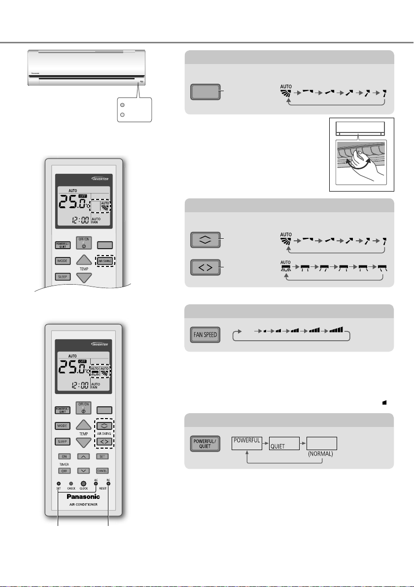
Consignes d’utilisation
FAN SPEEDFAN SPEED
To adjust airfl ow direction
Pour ajuster l’orientation du fl ux d’air
(CS-FZ25/35/50UKE)
Indicator
POWER
TIMER
CS-FZ25/35/50UKE
AIR SWING
•
Ne réglez pas le volet manuellement.
•
Pour l’orientation latérale, elle est
ajustable manuellement comme illustré.
To adjust airfl ow direction
Pour ajuster l’orientation du fl ux d’air
(CS-FZ60UKE)
AIR SWING
•
Ne réglez pas le volet manuellement.
Vers le haut
Vers le haut
Vers les côtés
Non utilisé
dans les
opérations
normales.
38
CS-FZ60UKE
FAN SPEED
Appuyez pour
revenir aux
réglages par
défaut de la
télécommande.
Pour régler la vitesse du ventilateur
AUTO
FAN
•
Pour AUTO, la vitesse du ventilateur intérieur est
automatiquement ajustée en fonction du mode de
fonctionnement.
•
Pour donner la priorité à un fonctionnement silencieux,
sélectionnez la vitesse de ventilateur la plus faible (
).
Pour passer de puissant à silencieux
PUISSANT :
Pour atteindre rapidement la température souhaitée
• Cette opération s’arrête automatiquement au bout
de 20 minutes.
SILENCE:
Pour Un Fonctionnement Silencieux
• Cette opération réduit le bruit du fl ux d’air.
Page 39
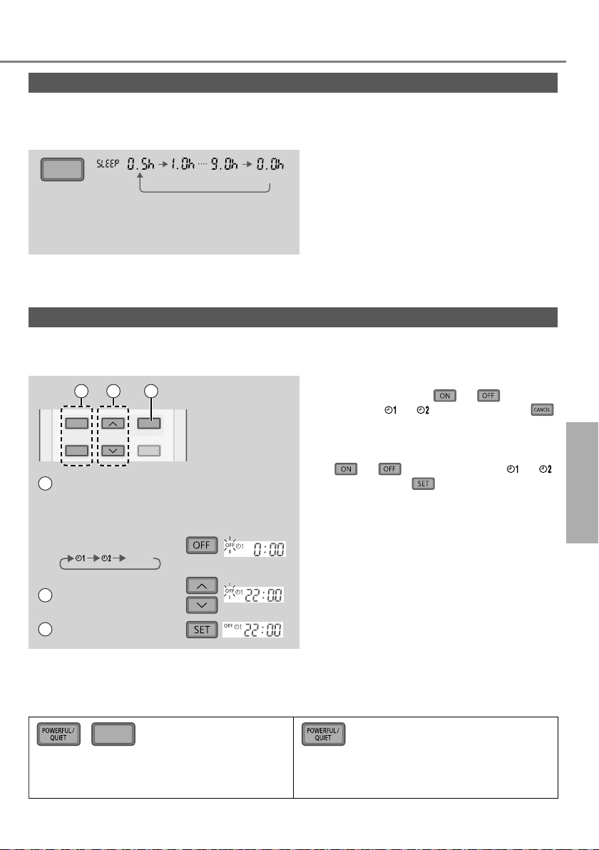
Voir « Pour en savoir plus… » pour les détails.
CANCEL
Pour un confort optimal pendant votre sommeil
Ce mode vous crée un environnement confortable pendant le sommeil. Il ajuste automatiquement la
température à la structure du sommeil pendant la période d’activation. Le témoin de l’unité intérieure
s’atténue lorsque ce mode est activé. Ceci ne s’applique pas si la luminosité du témoin a été atténuée.
•
SLEEP
(Annuler)
Ce mode est intégré au minuteur d’activation
(0,5, 1, 2, 3, 4, 5, 6, 7, 8 ou 9 heures).
Cette fonction peut être réglée avec le
minuteur. Quand il est utilisé conjointement
avec le minuteur d’arrêt, le mode sommeil a
la priorité.
•
Peut être annulé en appuyant sur la touche
respective jusqu’à atteindre 0.0h.
Pour régler l’heure
2 jeux de minuteurs de MARCHE et ARRÊT sont disponibles pour allumer et éteindre l’unité
à différentes heures préréglées.
•
21 3
ON
TIMER
OFF
Sélectionnez le
1
mode marche
(ON) ou arrêt de la
minuterie (OFF)
• À chaque pression:
Cancel
SET
CANCEL
Exemple :
ARRÊT à 22:00
Pour annuler le minuteur de MARCHE ou
ARRÊT, appuyez sur
sélectionner
ou puis appuyez sur .
ou pour
• Si le minuteur est annulé manuellement
ou à cause d’une panne d’électricité, vous
pouvez restaurer le minuteur en appuyant
sur
puis appuyez sur
ou pour sélectionner ou
.
• Le réglage de la minuterie le plus proche
s’affi chera et sera activé en séquence.
• L’opération de minuterie se base sur le
réglage de l’horloge de la télécommande
et se répète quotidiennement une fois
Consignes d’utilisation
Français
défi nie. Pour régler l’horloge, veuillez
2 Réglez l’heure
consulter le Guide rapide.
3 Confi rmez
Remarque
SLEEP
,
• Peut être activé dans tous les modes et
annulé en appuyant à nouveau sur la
touche respective.
•
Ne peut pas être sélectionné en même temps.
39
Page 40
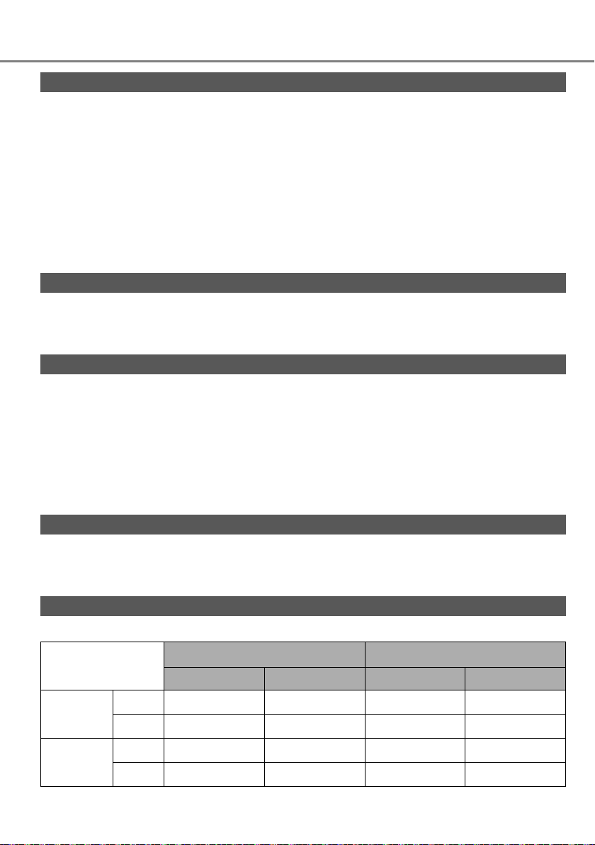
Pour en savoir plus...
Mode de fonctionnement
AUTO : Lors fonctionnement, le voyant POWER clignotera dans un premier temps.
CHAUFFAGE
REFROIDISSEMENT :
DÉSHUMIDIFICATION : L’unité fonctionne en vitesse lente du ventilateur pour fournir un
Réglage de la température pour économiser l’énergie
Le fait de faire fonctionner l’appareil dans la plage de température recommandée peut économiser l’énergie.
CHAUFFAGE : 20.0 °C ~ 24.0 °C /
REFROIDISSEMENT : 26.0 °C ~ 28.0 °C /
Direction du fl ux d’air
En mode REFROIDISSEMENT/DÉSHUMIDIFICATION :
(CS-FZ25/35/50UKE)
Si AUTO est défi ni, le volet oscille automatiquement vers le haut et vers le bas.
(CS-FZ60UKE)
Si AUTO est défi ni, le volet oscille automatiquement vers la gauche et la droite et vers le haut et le bas.
En mode CHAUFFAGE :
Si AUTO est réglé, le volet horizontal est défi ni sur une position prédéterminée. Le volet
vertical bascule vers la gauche/droite après l’augmentation de la température.
L’unité choisit le mode d’opération toutes les 10 minutes selon le réglage de la
température et la température ambiante.
:
Le voyant POWER clignote dans un premier temps au cours de cette
opération. L’appareil met un certain temps à démarrer.
• Sur les systèmes dont le mode HEAT (CHAUFFAGE) a été verrouillé, si un mode
de fonctionnement autre que le mode HEAT (CHAUFFAGE) est sélectionné,
l’unité intérieure s’arrête et le voyant d’alimentation POWER clignote.
Fournit un refroidissement effi cace et confortable adapté à vos besoins.
refroidissement en douceur.
68 °F ~ 75 °F.
79 °F ~ 82 °F.
Commande de redémarrage automatique
Si l’alimentation électrique est rétablie après une panne de courant, l’appareil redémarrera automatiquement
après une certaine période de temps avec le mode de fonctionnement et l’orientation du fl ux d’air précédents.
•
Cette commande n’est pas applicable lorsque la minuterie (TIMER) est réglée.
Conditions d’utilisation
Utilisez ce climatiseur en respectant la plage de températures suivante.
Température
REFROIDISSEMENT
CHAUFFAGE
DBT: Température sèche, WBT: Température humide
°C (°F)
Max. 32 (89.6) 23 (73.4) 43 (109.4) 26 (78.8)
Min. 16 (60.8) 11 (51.8) -10 (14.0) -
Max. 30 (86.0) - 24 (75.2) 18 (64.4)
Min. 16 (60.8) - -15 (5.0) -16 (3.2)
Unité intérieure Unité extérieure
DBT WBT DBT WBT
40
Page 41

Instructions de nettoyage
Pour garantir une performance optimale de l’unité, un
Unité intérieure
nettoyage doit être effectué à intervalles réguliers. La
saleté peut causer un dysfonctionnement et il peut
s’affi cher le code d’erreur « H 99 ». Veuillez consulter
Panneau avant
un revendeur agréé.
•
Coupez l’alimentation et débranchez l’appareil avant le nettoyage.
•
Ne touchez pas l’ailette en aluminium, la partie tranchante
peut provoquer des blessures.
•
N’utilisez pas de benzène, de solvant ou de poudre à récurer.
•
Utilisez uniquement du savon ( pH 7) ou un détergent
ménager neutre.
•
N’utilisez pas de l’eau dont la température est supérieure à
Filtre purifi cateur d’air
(CS-FZ25/35UKE)
40 °C / 104 °F.
Unité intérieure
Frottez délicatement l’appareil
avec un chiffon doux et sec.
Les bobines et les ventilateurs
doivent être nettoyés au
moins tous les 6 mois par un
revendeur agréé.
Unité extérieure
Enlevez les débris qui entourent
l’unité.
Enlevez toute obstruction du
Filtre à air
Une fois toutes les 2 semaines
•
Lavez/rincez les fi ltres avec
précaution avec de l’eau afi n
d’éviter d’endommager leur
surface.
•
Séchez complètement les fi ltres à l’ombre, à
distance du feu ou de la lumière directe du soleil.
• Si le fi ltre est endommagé, remplacez-le
immédiatement.
Retirez le fi ltre à air Fixez le fi ltre à air
tuyau d’évacuation.
Filtre purifi cateur d’air
• Ne lavez/rincez pas le fi ltre à l’eau.
• Remplacez le fi ltre tous les 2 ans ou
replacez tout fi ltre
endommagé.
N° de pièce: CZ-SA31P
Filtre à air
Insérez dans l’unité
Ailette En Aluminium
POWER
TIMER
Filtre purifi cateur d’air
(CS-FZ50/60UKE)
Français Pour en savoir plus... / Instructions de nettoyage
Filtre purifi cateur d’air
41
Page 42

Instructions de nettoyage
Panneau avant
Lavez avec soin et séchez.
Retirez le panneau avant
(Pour CS-FZ25/35/50UKE) (Pour CS-FZ60UKE)
Soulevez
1
Refermez bien
Pour les deux côtés
OWER
P
TIMER
Retirez.
3
Faites coulisser
2
vers la droite ou
vers la gauche.
Retirez.
2
Soulevez
1
POWER
TIMER
POWER
TIMER
Insérez des
1
deux côtés.
Fermer.
2
Appuyez sur les deux extrémités du panneau avant
3
42
Page 43

Dépannage
Les рhénomènes suivants ne correspondent pas à un dysfonctionnement.
Le voyant POWER clignote avant que l’unité ne soit
mise en route.
Le voyant POWER clignote pendant le mode CHAUFFAGE
sans fourniture d’air chaud (et le volet est fermé).
Le voyant POWER clignote et s’arrête
au cours du fonctionnement en mode
REFROIDISSEMENT/DÉSHUMIDIFICATION.
Le voyant TIMER reste allumé. • Une fois qu’une minuterie est réglée, son fonctionnement est
Le fonctionnement ralentit quelques minutes après
avoir remis en marche l’appareil.
Capacité de refroidissement/chauffage réduite
lorsque la vitesse de ventilateur la plus faible est
sélectionnée.
En mode de chauffage, le ventilateur intérieur
s’arrête de temps en temps.
En mode de réglage automatique de la vitesse du
ventilateur, le ventilateur intérieur s’arrête de temps
en temps.
Le fl ux d’air continue même après l’arrêt de l’unité. • Extraction de la chaleur restante dans l’unité intérieure (30
La pièce a une odeur étrange. •
Bruit de craquement pendant le fonctionnement. • Les fl uctuations de température provoquent l’expansion/ la
Lors du fonctionnement, vous entendez un bruit
d’eau qui coule.
De la vapeur se dégage de l’unité intérieure. •
L’unité extérieure dégage de la vapeur ou de l’eau. • De l’eau se condense ou s’évapore dans les tuyaux.
Poussière accumulée sur le mur. • Due à la circulation d’air ou à l’électricité statique générée
Décoloration de certaines pièces en plastique. •
Phénoméne Cause
• C’est une étape de préparation préliminaire à la mise en route
lorsque la minuterie de départ ON a été réglée. Lorsque le
mode minuterie est activé, il se peut que l’appareil démarre
avant l’heure réelle défi nie de façon à atteindre la température
que vous avez choisie (environ 35 minutes avant).
• L’unité est en mode dégivrage (et la fonction d’oscillation de
l’air (AIR SWING est réglée sur AUTO).
• Le système est verrouillé pour fonctionner en mode
CHAUFFAGE uniquement.
quotidien.
• Le ralentissement est une protection du compresseur de
l’appareil.
La vitesse de ventilateur la plus faible donnant la priorité à un
•
fonctionnement silencieux, la capacité de refroidissement/chauffage
peut être réduite (en fonction des conditions). Augmentez la vitesse du
ventilateur pour augmenter la capacité.
• Pour éviter un effet de refroidissement indésirable.
• Ceci contribue à dissiper les odeurs ambiantes.
seconde maximum).
Il est possible qu’il s’agisse d’une odeur d’humidité provenant du mur,
du tapis, d’un meuble ou d’un vêtement.
contraction de l’appareil.
• Fluide frigorigène à l’intérieur de l’appareil.
Il s’agit d’un effet de condensation dû au refroidissement.
par le climatiseur. Certains types de papier peint peuvent
capter la poussière facilement (il est recommandé de nettoyer
fréquemment la zone autour du climatiseur).
La décoloration dépend des types de matériaux utilisés dans les pièces en
plastique, accélérée en cas d’exposition à la chaleur, à la lumière du soleil,
aux rayons UV ou à un facteur environnemental.
Instructions de nettoyage / Dépannage
Français
Vérifi ez les éléments suivants avant de faire appel au service de maintenance.
La fonction CHAUFFAGE/REFROIDISSEMENT ne
fonctionne pas effi cacement.
L’appareil fait du bruit lorsqu’il fonctionne. • Vérifi ez que l’appareil est installé sans inclinaison.
La télécommande ne fonctionne pas.
(L’affi chage est atténué ou le signal émis est faible.)
L’appareil ne fonctionne pas. • Vérifi ez si le coupe-circuit est déclenché.
L’appareil ne reçoit pas le signal de la
télécommande.
Phénoméne Vérifi cation
• Réglez la température correctement.
• Fermez toutes les portes et fenêtres.
• Nettoyez ou remplacez les fi ltres.
• Dégagez toute obstruction dans les ouvertures d’entrée et de
sortie d’air.
• Fermez correctement le panneau avant.
• Insérez les piles correctement.
• Remplacez les piles faibles.
• Vérifi ez si des minuteries ont été réglées.
• Vérifi ez que le récepteur n’est pas obstrué.
• Certaines lampes fl uorescentes peuvent interférer avec le
signal de l’émetteur. Veuillez consulter un revendeur agréé.
43
Page 44

Dépannage
Lorsque...
■ La télécommande manque ou un dysfonctionnement est survenu
1.Soulevez le panneau avant.
2.Appuyez une fois sur la touche pour utiliser en mode AUTO.
3. Maintenez la touche enfoncée jusqu’au retentissement d’un bip, puis
relâchez pour utiliser en mode REFROIDISSEMENT forcé.
4. Répétez l’étape 3. Maintenez la touche enfoncée jusqu’au retentissement
de 2 bips, puis relâchez pour utiliser en mode CHAUFFAGE forcé.
5.Appuyez à nouveau sur la touche pour mettre l’appareil hors tension.
■ Les voyants sont trop lumineux
Pour atténuer ou restaurer la luminosité du voyant de l’unité, maintenez la touche
•
pendant 5 secondes.
■ Vous effectuez une inspection annuelle après une période prolongée d’inutilisation
• Vérifi ez les piles de la télécommande.
• Vérifi ez l’absence d’obstruction des orifi ces d’entrée et de sortie d’air.
• Utilisez le bouton de MARCHE/ARRÊT automatique pour sélectionner le mode
REFROIDISSEMENT/ CHAUFFAGE. Après 15 minutes d’opération, il est normal d’avoir la
différence suivante de température entre la prise d’air et la sortie de bouches d’aération:
REFROIDISSEMENT: ≥ 8 °C / 14.4 °F
■ Les unités ne seront pas utilisées pendant une période prolongée
• Activez le mode CHAUFFAGE pendant 2 à 3 heures pour éliminer en profondeur l’humidité
restée dans les pièces internes afi n d’éviter la formation de moisissures.
• Couper l’alimentation et débrancher.
• Retirez les piles de la télécommande.
CHAUFFAGE: ≥ 14 °C / 25.2 °F
enfoncée
PIECES NON SUSCEPTIBLES D’ETRE REPAREES PAR VOS SOINS
COUPEZ L’ALIMENTATION ÉLECTRIQUE ET DÉBRANCHEZ LA PRISE, puis contactez
un revendeur agréé dans les conditions suivantes:
• Bruits anormaux pendant la mise en service.
• Pénétration d’eau ou de corps étrangers à l’intérieur de la télécommande.
• Fuite d’eau de l’unité intérieure.
• Désactivation fréquente du disjoncteur.
• Le cordon d’alimentation est inhabituellement chaud.
• Les interrupteurs ou les boutons ne fonctionnent pas correctement.
44
Page 45

Comment récupérer les codes d’erreur
TIMER
S
CANCEL
ON
O
S
K
RES
C
RC
Si l’unité s’arrête et que le voyant TIMER clignote, utilisez la télécommande pour récupérer le code
d’erreur.
1
Appuyez sur cette
touche pendant au
moins 5 secondes
3
Appuyez à nouveau sur
cette touche lorsque la
vérifi cation est terminée
ON
TIMER
OFF
FF
SET CHECK CLOCK RESET
ET CLOC
SET
CANCEL
A
AC
ET
• Pour certaines erreurs, il suffi t de redémarrer l’unité en fonctionnement limité si 4 bips sont émis au
cours du démarrage.
Affi chage
diagnostic
H 00
H 11
H 12
H 14
H 15
H 16
H 17
H 19
H 21
H 23
H 24
H 25
H 26
H 27
H 28
H 30
H 31
H 32
H 33
H 34
H 35
H 36
H 37
H 38
H 39
H 41
Contrôle des anomalies/protection
Aucune panne en mémoire
Communication anormale entre les unités
intérieure/extérieure
Capacité de l’unité intérieure incompatible
Anomalie liée au capteur de température de
l’admission de l’unité intérieure
Anomalie liée au capteur de température du
compresseur de l’unité extérieure
Anomalie liée au transformateur de courant
(CT) de l’unité extérieure
Anomalie liée au capteur de température
d’aspiration de l’unité extérieure
Blocage du mécanisme du moteur de
ventilateur de l’unité intérieure
Anomalie liée au fonctionnement de
l’interrupteur à fl otteur de l’unité intérieure
Anomalie liée au capteur de température 1 de
l’échangeur thermique de l’unité intérieure
Indoor heat exchanger temperature
sensor 2 abnormality
Anomalie liée au capteur de température 2 de
l’échangeur thermique de l’unité intérieure
Anomalie liée à Minus ION
Anomalie liée au capteur de température
de l’air extérieur
Anomalie liée au capteur de température 1 de
l’échangeur thermique de l’unité extérieure
Anomalie liée au capteur de température du
tuyau d’évacuation de l’unité extérieure
Anomalie du capteur de piscine
Anomalie liée au capteur de température 2 de
l’échangeur thermique de l’unité extérieure
Anomalie liée aux erreurs de raccordement
des unités intérieure/extérieure
Anomalie liée au capteur de température du
dissipateur thermique de l’unité extérieure
Anomalie liée au courant d’eau négatif
entre les unités intérieure/extérieure
Anomalie liée au capteur de température du
tuyau de gaz de l’unité extérieure
Anomalie liée au capteur de température du
tuyau de liquide de l’unité extérieure
Incompatibilité entre les unités intérieure/
extérieure (code de marque)
Anomalie liée à l’unité de fonctionnement
intérieure ou aux unités de veille
Anomalie liée au raccordement des câblages ou
des tuyauteries
* Certains codes erreur peuvent ne pas être applicables à votre modèle.Consultez un revendeur agréé pour plus
d’explications.
ET
RC
2
Appuyez sur cette touche jusqu’à ce
que vous entendiez un bip, puis notez le
code d’erreur
4
Éteindre l’appareil et donner le code
d’erreur à un revendeur agréé
Affi chage
diagnostic
H 50
H 51
H 52
H 58
H 59
H 64
H 67
H 70
H 71
H 72
H 97
H 98
H 99
F 11
F 16
F 17
F 18
F 87
F 90
F 91
F 93
F 94
F 95
F 96
F 97
F 98
F 99
Contrôle des anomalies/protection
Blocage du moteur de ventilateur
Blocage du moteur de ventilateur
Anomalie liée à la fi xation du commutateur de
limite gauche-droite
Anomalie liée au capteur de gaz de l’unité
intérieure
Anomalie liée au capteur éco
Anomalie liée au capteur haute pression de
l’unité extérieure
Anomalie liée à la function nanoe
Anomalie liée au capteur de lumière
Anomalie liée ventilateur de refroidissement
CC à l’intérieur du tableau de commande
Anomalie liée au capteur de température
du réservoir
Blocage du mécanisme du moteur de ventilateur
de l’unité extérieure
Protection contre la haute pression de l’unité
intérieure
Protection contre le gel de l’unité de
fonctionnement intérieure
Anomalie liée à la commutation de la vanne
4 voies
Protection du courant de fonctionnement total
Anomalie liée au gel des unités de veille
intérieures
Anomalie liée au blocage du circuit sec
Protection contre la surchauffe du boîtier de
commande
Protection du circuit Power Factor Correction
(PFC ou Correction du facteur de puissance)
Anomalie liée au cycle de réfrigération
Révolution anormale du compresseur de l’unité
extérieure
Protection contre les dépassements de
pression de l’évacuation du compresseur
Protection contre la haute pression du
refroidissement de l’unité extérieure
Protection contre la surchauffe du module du
transistor de puissance
Protection contre la surchauffe du compresseur
Protection du courant de fonctionnement total
Détection des pics de courant continu (CC) de
l’unité extérieure
Dépannage
Français
45
Page 46

Ofrece máximo confort con métodos óptimos
FAN SPEED
FAN SPEED
de ahorro energético.
Utilice el mando
a distancia a
un máximo de
8 metros desde
el receptor del
mando a distancia
de la unidad
interior.
* La pantalla y las
funciones del mando
a distancia pueden
cambiar en función del
modelo.
46
Guía Rápida
Colocación de las pilas
B
Retire la tapa trasera
1
A
del mando a distancia.
Inserte pilas AAA o R03.
2
Cierre la tapa.
3
1
2
3
A
Confi guración del reloj
Pulse
1
hora
•
Pulse y sostenga
y ajuste la
.
durante aproximadamente
5 segundos para mostrar
la hora en el formato de 12
(am/pm) o 24 hora.
Confi rmar .
2
Page 47

Muchas gracias por elegir una unidad
de aire acondicionado Panasonic
.
Contenido
Precauciones de seguridad
Forma de uso
...............................
Obtener más información
Instrucciones de lavado
Localización de averías
Información
....................................................
....
48-59
60-61
...............
62
.........
63-64
.........
65-67
70
Accesorios
• Mando a distancia
• 2 x pilas AAA o R03
• Soporte del control remoto
• 2 x tornillos para el soporte
del mando a distancia
Las ilustraciones de este manual
sirven únicamente para describir las
explicaciones y pueden no coincidir
exactamente con las del aparato
suministrado. Están sujetas a cambios
sin previo aviso con el fi n de mejorar el
producto.
B
Funcionamiento básico
Seleccione el modo
1
deseado presionando
.
AUTO HEAT
DRY
COOL
Pulse para
2
iniciar/detener el
funcionamiento.
POWER
• Para encender la
unidad observe
si se muestra la
indicación
Seleccione la temperature
3
deseada.
Arriba
Abajo
Español
Gama de selección:
16.0 °C ~ 30.0 °C /
60 °F ~ 86 °F.
• Presione y sostenga
durante aproximadamente
.
10 segundos para mostrar
la temperatura en °C o °F.
47
Page 48
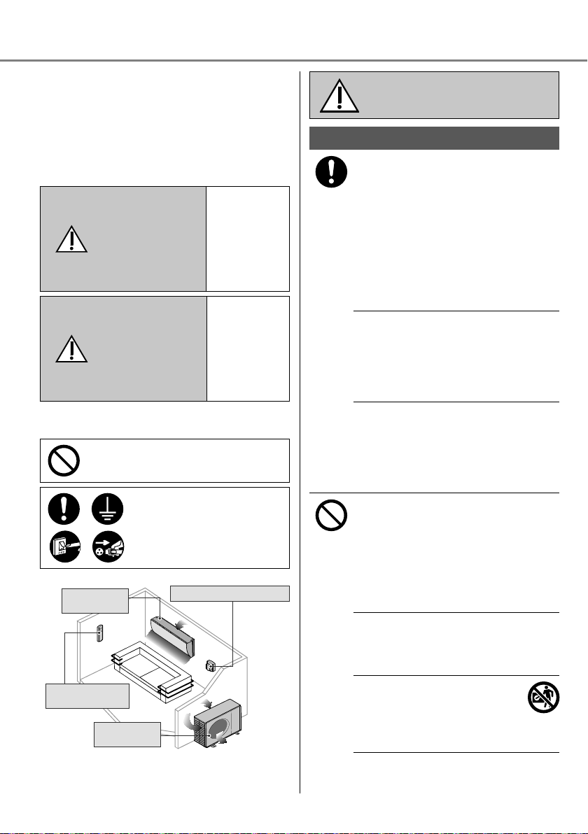
Precauciones de seguridad
Entrada de
aire
Entrada de
aire
Salida de
aire
Salida de
aire
Para evitar lesiones personales, lesiones a
terceros, o daños materiales, cumpla lo siguiente:
El uso incorrecto por no seguir las instrucciones
puede causar daños o averías; su gravedad se
clasifi ca con las indicaciones siguientes:
Este aparato no está pensado para ser
manipulado por el público en general.
Esta
indicación
advierte del
ADVERTENCIA
PRECAUCIÓN
Las instrucciones que deben seguirse están
clasifi cadas mediante los siguientes símbolos:
Este símbolo denota una
acción que está PROHIBIDA.
Estos símbolos indican
aquellas acciones que son
OBLIGATORIAS.
Unidad
interior
Mando a
distancia
Unidad
exterior
Salida de
aire
Entrada de
Entrada de
aire
posible peligro
de muerte
o de daños
graves.
Esta
indicación
advierte de
los posibles
daños o
desperfectos
materiales.
Fuente de energía
aire
Salida de
aire
Unidad interior y unidad exterior
ADVERTENCIA
Este aparato puede ser utilizado por
niños a partir de 8 años y personas con
dicapacidad física, sensorial o mental
o falta de experiencia y conocimientos
si están bajo supervisión o han recibido
instrucciones relativas al uso del aparato
de un modo seguro y comprenden los
riesgos implícitos.
Los niños no deben jugar con el aparato.
La limpieza y el mantenimiento no debe
ser realizado por niños sin supervisión.
Por favor, consulte a un distribuidor
autorizado o especialista para limpiar las
partes internas, reparar, instalar, eliminar
y reinstalar la unidad. Una incorrecta
manipulación e instalación puede causar
fugas, descargas eléctricas o incendios.
Confi rme con el servicio técnico
autorizado o el especialista el uso del
tipo de refrigerante especifi cado. Utilizar
un tipo de refrigerante diferente al tipo
especifi cado puede provocar daños en
el producto, explosiones y lesiones, etc.
No utilice ningún medio para acelerar
el proceso de descongelación ni
para la limpieza, a excepción de los
recomendados por el fabricante.
Cualquier método inadecuado o el uso
de materiales incompatibles pueden
causar daños al producto, el estallido del
sistema y lesiones graves.
No instale la unidad en ambientes
potencialmente explosivos o infl amables.
En caso contrario, podría provocar
accidentes de incendios.
No introduzca los dedos u otros
objetos en la unidad exterior o
interior del aire acondicionado, ya
que las partes rotatorias podrían
provocarle lesiones.
48
Page 49
No toque la unidad exterior durante un
relámpago, ya que podría causar una
descarga eléctrica.
Para evitar el excesivo enfriamiento no
se exponga directamente al aire frío
durante un prolongado período.
No se siente o apoye sobre
la unidad; se podría caer
accidentalmente.
Mando a distancia
No permita que ni bebés ni niños
pequeños jueguen con el mando a
distancia para evitar que ingieran
accidentalmente las pilas.
Fuente de energía
No utilice un cable
modifi cado, unido
con otro, un cable de
extensión o un cable no
especifi cado para evitar
sobrecalentamiento e
incendios.
Para evitar el sobrecalentamiento,
incendio o descarga eléctrica:
•
No comparta la misma toma de
corriente con otros equipos.
•
No lo manipule con las manos
mojadas.
•
No doble excesivamente el cable de
alimentación.
•
No encienda ni apague la unidad
conectando o desconectando el
enchufe de alimentación.
Para evitar riesgos, si el cable de
alimentación está dañado y es necesario
cambiarlo, deberá hacerlo el fabricante,
un representante del servicio técnico o
una persona cualifi cada.
Se recomienda altamente instalarlo con
un disyuntor de fuga a tierra (ELCB) o
un dispositivo residual actual (RCD) para
evitar descargas eléctricas o incendios.
Para evitar el sobrecalentamiento,
incendio o descarga eléctrica:
•
Inserte el enchufe correctamente.
•
El polvo en el enchufe de alimentación
debe ser limpiado periódicamente con
un paño seco.
Deje de utilizar el producto cuando haya
cualquier anormalidad/fallo y desconecte
el cable de corriente o desactive el
interruptor de alimentación.
(Riesgo de humo/fuego/descarga
eléctrica)
Ejemplos de anomalía/fallo
•
El ELCB se desconecta
frecuentemente.
•
Se percibe olor a humo.
•
Se observa ruido anormal o vibración
en la unidad.
•
Filtraciones de agua desde la unidad
interior.
•
El cable de alimentación o el enchufe
está excesivamente caliente.
•
No se puede controlar la velocidad del
ventilador.
•
La unidad se para inmediatamente
incluso estando en funcionamiento.
•
El ventilador no se para incluso
habiendo cesado la operación.
Contacte inmediatamente con su
proveedor local para su mantenimiento/
reparación.
Este equipo deberá conectarse a tierra
para evitar descargas eléctricas o
incendios.
Evite las descargas eléctricas apagando
el interruptor de alimentación y
desenchufando la unidad:
- Antes de limpiarlo o repararlo,
- Cuando no vaya a utilizarla durante un
largo periodo, o
- Durante tormentas eléctricas
especialmente violentas.
Español Precauciones de seguridad
49
Page 50
Precauciones de seguridad
Evite las fugas de agua asegurándose
PRECAUCIÓN
Unidad interior y unidad exterior
No lave la unidad interior con agua,
benceno, disolvente o limpiador en
polvo para evitar daños o corrosión en
la unidad.
No utilice la unidad a fi nes de
conservación de: equipos de precisión,
alimentos, animales, plantas, obras de
arte u otros objetos. Podría causar un
deterioro en su calidad, etc.
No utilice ningún equipo combustible
delante de la salida de aire pare evitar
que se propague un incendio.
Para prevenir lesiones, etc no exponga
directamente al fl ujo del aire plantas o
animales de compañía.
No tocar las partes de aluminio
angulosas, pueden causar daños.
No encienda la unidad cuando encere
el suelo. Después de encerar, airee la
habitación correctamente antes de usar
la unidad.
Para evitar daños a la unidad no la
instale en zonas grasas y con humo.
Para evitar lesiones no desmonte la
unidad para su limpieza.
Para evitar lesiones durante la limpieza
de la unidad sitúese sobre una superfi cie
estable.
No coloque un jarrón o un recipiente
que contenga liquido sobre la unidad.
El agua podría entrar en el interior de
la unidad y degradar. El aislamiento
causando una descarga eléctrica.
No abra la ventana ni la puerta por un
periodo de tiempo prolongado durante
el funcionamiento, ya que ello podría
dar lugar a un consumo de energía
inefi ciente y a molestos cambios de
temperatura.
de que la tubería de drenaje esté:
- Correctamente conectada,
- Libre de colmos de agua y recipientes,
o
- No sumergida en el agua
Airear la habitación regularmente
después de su uso durante un
prolungado período o tras el empleo de
cualquier equipo combustibile.
Después de un largo periodo de
uso, asegúrese de que la ranura de
instalación no se encuentre deteriorada,
para evitar que la unidad se caiga.
Mando a distancia
No utilice pilas recargables (Ni-Cd).
Podría dañar el control remoto.
Para evitar mal funcionamiento o
deterioro del control remoto:
•
Extraiga las pilas si no va a utilizar la
unidad durante un periodo prolongado
de tiempo.
•
Las baterías nuevas deben ser del
mismo tipo y se insertan siguiendo
las indicaciones de la polaridad
segnaladas.
Fuente de energía
Para evitar descargas eléctricas durante
la desconexión del enchufe no tire del
cable para desenchufarlo.
50
Page 51
ADVERTENCIA
Este aparato se carga con
R32 (in refrigerante de baja
infl amabilidad).
Si se produce una fuga de
refrigerante y este queda
expuesto a una fuente externa
de ignición, existe peligro de
incendio.
Unidad interior y unidad exterior
Este aparato debe instalarse y/o
utilizarse en una habitación con un área
superior a Amín (m²) y mantenerse
lejos de fuentes de ignición, tales como
calor, chispas o llamas al descubierto, o
zonas peligrosas, tales como aparatos
de gas, cocinas de gas, sistemas de
suministro de gas reticulados, aparatos
de refrigeración eléctricos, etc.(Consulte
la Tabla A en la tabla de Instrucciones
de instalación para conocer el valor de
Amín (m²))
Tenga en cuenta que es posible que
el refrigerante no contenga ninguna
sustancia para dotarlo de olor. Es
altamente recomendable contar en
todo momento con detectores de gas
refrigerante infl amable en perfecto
estado de funcionamiento y capaces de
advertir de la presencia de una fuga.
Mantenga las aberturas de ventilación
necesarias libres de obstrucciones.
No perfore ni exponga el aparato al
fuego mientras está presurizado. No
exponga el aparato al calor, llamas,
chispas ni otras fuentes de ignición. De
lo contrario podría estallar y provocar
lesiones o la muerte.
Precauciones para el uso del
refrigerante R32
Los procedimientos básicos de trabajo de
instalación son los mismos que los de los
modelos con refrigerantes convencionales
(R410A, R22).
Dado que la presión de funcionamiento
es superior a la de los modelos con
refrigerante R22, algunas tuberías y
herramientas de instalación y servicio
son especiales. Especialmente al
sustituir un modelo con refrigerante R22
por un nuevo modelo con refrigerante
R32, sustituya siempre las tuberías y
tuercas cónicas convencionales por las
tuberías y tuercas cónicas de R32 y
R410A en el lado exterior de la unidad.
En el caso de R32 y R410A, se puede
utilizar la misma tuerca cónica en el lado
de la unidad exterior y el tubo.
Se prohíbe la mezcla de distintos
refrigerantes dentro de un sistema. Los
modelos que utilizan refrigerante R32 y
R410A presentan un diámetro de rosca
diferente del puerto de carga para evitar
una carga errónea con refrigerante R22
y también por motivos de seguridad.
Por tanto, compruébelo de antemano.
[El diámetro de rosca del puerto de
carga de R32 y R410A es de 1/2 pulg.]
Asegúrese siempre que material extraño
(aceite, agua, etc.) no penetre en las
tuberías. Asimismo, al almacenar los
tubos, selle de forma segura la abertura
mediante pinzamiento, cinta adhesiva,
etc. (La manipulación del R32 es similar
a la del R410A.)
•
Solo personal certifi cado y cualifi cado
debe llevar a cabo la operación, el
mantenimiento, las reparaciones y la
recuperación de refrigerante en el uso
de refrigerantes infl amables y según
las recomendaciones del fabricante. El
personal que lleve a cabo la operación,
las reparaciones o el mantenimiento de
un sistema o las piezas asociadas del
equipo debe estar capacitado y contar
con certifi cación.
Español Precauciones de seguridad
51
Page 52
Precauciones de seguridad
•
Ninguna pieza del circuito de
refrigeración (evaporadores,
refrigeradores de aire, unidades
de tratamiento de aire (AHU),
condensadores o recipientes de
líquido) ni de la tubería debe estar
ubicada cerca de fuentes de calor,
llamas expuestas, aparatos de gas o
calentadores eléctricos.
•
El usuario/propietario o su
representante autorizado debe
comprobar regularmente las
alarmas, la ventilación mecánica y
los detectores, al menos una vez al
año, según las disposiciones de las
normas nacionales, para garantizar el
funcionamiento correcto.
•
Se debe conservar un libro de registros.
El resultado de estas verifi caciones se
debe registrar en el libro.
•
En el caso de ventilaciones que se
encuentren en espacios ocupados,
se debe confi rmar que no presenten
obstrucciones.
•
Antes de poner en funcionamiento
un sistema de refrigeración nuevo,
la persona responsable de poner en
servicio el sistema debe asegurarse de
que personal capacitado y certifi cado
conozca las directrices del manual
de instrucciones sobre el montaje,
la supervisión, el funcionamiento
y el mantenimiento del sistema de
refrigeración, así como las medidas
de seguridad que se deben cumplir,
las propiedades y el manejo del
refrigerante utilizado.
•
A continuación, se muestran los
requisitos generales del personal
capacitado y certifi cado:
a) Conocimiento acerca de la
legislación, normas y estándares
relacionados con los refrigerantes
infl amables.
b) Profundo conocimiento sobre los
refrigerantes infl amables y su
manipulación, equipo de protección
individual, prevención de fugas del
refrigerante, manejo de cilindros,
carga, detección de fugas,
recuperación y descarte.
c) Poder entender y aplicar en la
d) Realizar capacitaciones
1. Instalación (Espacio)
•
Los productos con refrigerantes
infl amables no se deben instalar en un
espacio sin ventilación, si ese espacio
es menor que el valor de Amín (m²).
•
En el caso de carga en el campo, se
debe cuantifi car, medir y etiquetar
el efecto en la carga del refrigerante
causada por la longitud de las distintas
tuberías.
•
Asegúrese de que los tubos instalados
tengan la mínima longitud posible. Evite
el uso de tubos abollados y no permita
codos cerrados.
•
Asegúrese de proteger los tubos frente
a daños físicos.
•
Asegúrese de que se cumplan los
reglamentos nacionales relativos a
los gases, así como las normas y la
legislación municipales y nacionales.
Informe a las autoridades competentes
de acuerdo con todos los reglamentos
aplicables.
•
Asegúrese de que las uniones
mecánicas sean accesibles para la
realización del mantenimiento.
•
En los casos en los que se requiera
una ventilación mecánica, las aberturas
de ventilación deben mantenerse libres
de obstrucciones.
•
Al eliminar el producto, siga las
precauciones del apartado #12 y
cumpla los reglamentos nacionales.
Contacte siempre con las ofi cinas
municipales locales para una
manipulación adecuada.
práctica los requisitos de las leyes,
normas y estándares nacionales.
continuamente para mantener la
especialización.
52
Page 53
2. Mantenimiento
2-1. Personal de servicio
•
Solo personal de servicio capacitado
y certifi cado (contratado por el usuario
o tercero responsable) inspecciona,
supervisa regularmente y realiza el
mantenimiento del sistema.
•
Asegúrese de que el tamaño real de
la carga de refrigerante corresponda
al tamaño de la habitación en la que
se instalan los componentes que
contienen refrigerante.
•
Asegúrese de que la carga de
refrigerante no presente fugas.
•
Cualquier persona cualifi cada que
intervenga en el trabajo o la apertura
de un circuito de refrigerante debe
contar con un certifi cado vigente
emitido por una autoridad de
evaluación acreditada por la industria,
el cual autorice su competencia para la
manipulación segura de refrigerantes
de acuerdo con una especifi cación de
evaluación reconocida por la industria.
•
El mantenimiento solo debe realizarse
de la forma recomendada por el
fabricante del equipo. Los trabajos
de mantenimiento y reparación que
requieran la ayuda de otra persona
cualifi cada deben realizarse bajo la
supervisión de la persona competente
en el uso de refrigerantes infl amables.
•
El mantenimiento solo debe realizarse
de la forma recomendada por el
fabricante.
2-2. Trabajo
•
Antes de iniciar el trabajo en
sistemas que contienen refrigerantes
infl amables, es necesario realizar
comprobaciones de seguridad para
asegurar que el riesgo de ignición sea
mínimo. A la hora de reparar el sistema
de refrigeración, deben cumplirse las
precauciones de los apartados #2-2 a
#2-8 antes de realizar cualquier trabajo
en el sistema.
•
El trabajo debe realizarse con un
procedimiento controlado para
minimizar el riesgo de presencia de
gas o vapor infl amables durante la
realización del trabajo.
•
Todo el personal de mantenimiento y
otras personas que trabajen en el área
deben recibir formación y supervisión
acerca de la naturaleza del trabajo
realizado.
•
Evite el trabajo en espacios limitados.
Mantenga siempre una distancia de
seguridad de al menos 2 metros de la
fuente o un área libre de un radio de 2
metros.
•
Lleve equipos de protección
adecuados, incluida protección
respiratoria, según lo justifi quen las
condiciones.
•
Asegúrese de que las condiciones
dentro del área sean seguras, mediante
la limitación del uso de cualquier
material infl amable. Mantenga alejadas
todas las fuentes de ignición y
superfi cies metálicas calientes.
Precauciones de seguridad
Español
53
Page 54
Precauciones de seguridad
2-3. Comprobación de la presencia de
refrigerante
•
Se debe inspeccionar el área con un
detector de refrigerante adecuado
antes y durante el trabajo para
asegurar que el técnico esté al tanto
de las atmósferas potencialmente
infl amables.
•
Asegúrese de que el equipo de
detección de fugas utilizado sea
adecuado para su uso con refrigerantes
infl amables, es decir, que no emita
chispas, esté sellado sufi cientemente o
sea intrínsecamente seguro.
•
En caso de que se produzca una fuga o
derrame, ventile el área de inmediato y
permanezca en la parte de donde sopla
el viento y lejos del derrame o escape.
•
En caso de que se produzca una fuga o
derrame, informe a las personas que se
encuentren a favor del viento de la fuga
o vertido, aísle de inmediato el área de
peligro e impida el acceso a personal
no autorizado.
2-4. Presencia de un extintor
•
Si se va a realizar cualquier trabajo en
caliente en el equipo de refrigeración
o cualquier componente asociado,
se debe tener a mano un equipo de
extinción adecuado.
•
Disponga de un extintor de polvo seco
o de CO
junto al área de carga.
2
2-5. Ausencia de fuentes de ignición
•
Ninguna persona que realice trabajos
relacionados con un sistema de
refrigeración que impliquen la
exposición de una tubería que
contenga o haya contenido refrigerante
infl amable debe utilizar ninguna fuente
de ignición de manera tal que pueda
dar lugar a un riesgo de incendio o
explosión. No debe fumar al realizar
dicho trabajo.
•
Todas las fuentes de ignición posibles,
incluidos los cigarrillos encendidos,
deben mantenerse lo sufi cientemente
lejos del lugar de instalación,
reparación, retirada y eliminación, ya
que el refrigerante infl amable podría
liberarse al espacio circundante
durante el trabajo.
•
Antes de realizar el trabajo, se debe
inspeccionar el área circundante al
equipo para asegurar que no existan
peligros infl amables ni riesgos de
ignición.
•
Se deben colocar letreros de “No
fumar”.
2-6. Área ventilada
•
Asegúrese de que el área esté al aire
libre o sufi cientemente ventilada antes
de abrir el sistema o realizar cualquier
trabajo en caliente.
•
Debe seguir existiendo un grado de
ventilación durante el periodo en el que
se realice el trabajo.
•
La ventilación debe dispersar de forma
segura cualquier refrigerante liberado
y preferiblemente expulsarlo a la
atmósfera.
54
Page 55

2-7. Comprobaciones de los equipos
de refrigeración
•
Cuando se sustituyan componentes
eléctricos, estos deben ser aptos para
su propósito y cumplir la especifi cación
correcta.
•
En todo momento deben seguirse las
directrices de mantenimiento y servicio
del fabricante.
•
En caso de duda, solicite ayuda al
departamento técnico del fabricante.
•
Se deben efectuar las siguientes
comprobaciones en las instalaciones
que utilizan refrigerantes infl amables.
-
El tamaño de carga es conforme al
tamaño de la habitación en la que
se instalan los componentes que
contienen refrigerante.
-
La maquinaria y salidas de
ventilación funcionan sufi cientemente
y no están obstruidas.
-
Si se utiliza un circuito de
refrigeración indirecta, se debe
comprobar la presencia de
refrigerante en el circuito secundario.
-
El marcado del equipo sigue siendo
visible y legible. Debe corregirse
cualquier marcado o letrero ilegible.
-
El tubo o los componentes de
refrigeración están instalados
en una posición en la que es
improbable que queden expuestos
a ninguna sustancia que pueda
corroer los componentes que
contienen refrigerante, excepto si
los componentes están construidos
con materiales intrínsecamente
resistentes a la corrosión o
protegidos adecuadamente frente a
la corrosión.
2-8. Comprobaciones de los
dispositivos eléctricos
•
La reparación y el mantenimiento de
componentes eléctricos deben incluir
comprobaciones iniciales de seguridad
y procedimientos de inspección de
componentes.
•
A continuación se indican algunas
de las comprobaciones iniciales de
seguridad:
-
Los condensadores están
descargados: debe realizar esta
comprobación de forma segura para
evitar la posibilidad de emisión de
chispas.
-
No hay componentes eléctricos
conectados y el cableado está
expuesto durante la carga,
recuperación o purga del sistema.
-
Existe continuidad de conexión
equipotencial a tierra.
•
En todo momento deben seguirse las
directrices de mantenimiento y servicio
del fabricante.
•
En caso de duda, solicite ayuda al
departamento técnico del fabricante.
•
Si se produce una avería que pudiera
comprometer la seguridad, no se
debe conectar ninguna alimentación
eléctrica al circuito hasta que
se haya solucionado la avería
satisfactoriamente.
•
Si no se puede corregir la avería de
inmediato y es necesario mantener el
funcionamiento, debe aplicarse una
solución temporal sufi ciente.
•
Se debe informar al propietario del
equipo para que todas las partes estén
avisadas en adelante.
Precauciones de seguridad
Español
55
Page 56

Precauciones de seguridad
3. Reparaciones de componentes
sellados
•
Durante las reparaciones de
componentes sellados, se deben
desconectar todo el suministro
eléctrico del equipo con el que se vaya
a trabajar antes de retirar cualquier
cubierta sellada, etc.
•
Si es absolutamente necesario tener
conectada una alimentación eléctrica al
equipo durante el mantenimiento, debe
instalarse una forma de detección de
fugas en funcionamiento constante en
el punto más crítico para advertir de
una situación potencialmente peligrosa.
•
Se debe prestar especial atención
a lo siguiente para asegurar que, al
trabajar en los componentes eléctricos,
no se modifi que la carcasa en una
medida que perjudique al nivel de
protección. Ejemplos de una protección
perjudicada son daños en los cables,
número excesivo de conexiones,
bornes no realizados según la
especifi cación original, daños en los
sellos, ajuste incorrecto de casquillos,
etc.
•
Asegúrese de que el aparato esté
montado correctamente.
•
Asegúrese de que los sellos o
materiales de sellado no se hayan
degradado de manera tal que ya no
sirvan para su propósito de evitar la
entrada de atmósferas infl amables.
•
Todos los repuestos deben respetar las
especifi caciones del fabricante.
NOTA: El uso de sellantes de silicona
puede inhibir la efi cacia de ciertos tipos
de equipos de detección de fugas.
No es necesario aislar los componentes
intrínsecamente seguros antes de
trabajar en ellos.
4. Reparaciones en los componentes
intrínsecamente seguros
•
No aplique ninguna carga inductiva o
de capacitancia permanente al circuito
sin antes asegurarse de que tal acción
no rebasará en ningún caso la tensión
ni la corriente permitidas del equipo
utilizado.
•
Los componentes intrínsecamente
seguros son los únicos componentes
en los que se puede trabajar con
presencia de atmósfera infl amable.
•
El aparato de prueba debe presentar
unos parámetros nominales correctos.
•
Sustituya los componentes únicamente
con los repuestos especifi cados por
el fabricante. El uso de repuestos no
especifi cados por el fabricante podría
dar lugar a la ignición del refrigerante
en la atmósfera formada por una fuga.
5. Cableado
•
Asegúrese de que el cableado no
sufra desgaste, corrosión, presión
excesiva, vibración, exposición a
bordes cortantes ni ningún otro efecto
medioambiental adverso.
•
La comprobación también debe
tomar en cuenta los efectos del
envejecimiento o de la vibración
continua proveniente de fuentes tales
como compresores o ventiladores.
6. Detección de refrigerantes
infl amables
•
Bajo ninguna circunstancia deben
usarse fuentes potenciales de ignición
para la búsqueda ni la detección de
fugas de refrigerante.
•
No debe utilizarse en ningún caso
un soplete de haluro (ni ningún otro
detector basado en una llama al
descubierto).
56
Page 57
7. Métodos de detección de fugas
Los siguientes métodos de detección
de fugas se consideran aceptables para
todos los sistemas de refrigerante.
•
No se deben detectar fugas al utilizar
el equipo de detección con capacidad
−6
de 10
Pa·m3/s o más, por ejemplo, un
husmeador de helio.
•
Pueden utilizarse detectores de
fugas electrónicos para detectar los
refrigerantes infl amables, aunque su
sensibilidad quizá no sea adecuada o
requieran una recalibración.
(Los equipos de detección deben
calibrarse en un área que no contenga
refrigerante.)
•
Asegúrese de que el detector no
constituya una fuente potencial de
ignición y sea adecuado para el
refrigerante utilizado.
•
Los equipos de detección de fugas
deben estar regulados en un porcentaje
del LII del refrigerante y se deben
calibrar para el refrigerante empleado
y el porcentaje adecuado de gas (25%
como máximo) confi rmado.
•
Con la mayoría de los refrigerantes
pueden utilizarse fl uidos de detección
de fugas, pero debe evitarse el uso
de detergentes que contengan cloro,
dado que este puede reaccionar con
el refrigerante y corroer los tubos de
cobre.
•
Si se sospecha de una fuga, se deben
eliminar/apagar todas las llamas al
descubierto.
•
Si se detecta una fuga de refrigerante
que requiere soldadura fuerte, se
deberá recuperar todo el refrigerante
del sistema, o bien aislarlo (mediante
válvulas de corte) en una parte del
sistema que esté alejada de la fuga. A
continuación, se debe purgar el sistema
con nitrógeno sin oxígeno (OFN), tanto
antes del proceso de soldadura fuerte
como durante el mismo.
OFN = nitrógeno sin oxígeno, tipo
de gas inerte.
8. Extracción y evacuación
•
Al abrir el circuito de refrigerante
para realizar reparaciones – o para
cualquier otro fi n – se deberán seguir
los procedimientos convencionales.
Sin embargo, es importante seguir
las mejores prácticas dado que
la infl amabilidad es una cuestión
a considerar. Se debe respetar el
siguiente procedimiento: extraer el
refrigerante -> purgar el circuito con
gas inerte -> evacuar -> purgar de
nuevo con gas inerte -> abrir el circuito
mediante corte o soldadura fuerte
•
Se debe recuperar la carga de
refrigerante a los cilindros de
recuperación correctos.
•
El sistema se debe “lavar” con OFN
para garantizar la seguridad de la
unidad.
•
Es posible que sea necesario repetir
este proceso varias veces.
•
Para esta tarea no debe utilizarse aire
comprimido ni oxígeno.
•
El lavado se realiza rompiendo el vacío
del sistema con OFN y llenando hasta
alcanzar la presión de funcionamiento,
para después ventilar a la atmósfera y
fi nalmente reducir a un vacío.
•
Se debe repetir este proceso hasta que
no quede refrigerante en el sistema.
•
Cuando se utiliza la carga fi nal de
OFN, el sistema debe ventilarse hasta
Precauciones de seguridad
alcanzar la presión atmosférica para
permitir la realización del trabajo.
•
Esta operación es absolutamente
fundamental si deben realizarse
operaciones de soldadura fuerte en las
tuberías.
•
Asegúrese de que la salida de la
Español
bomba de vacío no esté próxima a
ninguna fuente de ignición y que exista
ventilación.
57
Page 58

Precauciones de seguridad
9. Procedimientos de carga
•
Además de los procedimientos de
carga convencionales, deben cumplirse
los siguientes requisitos.
-
Asegúrese de que los distintos
refrigerantes no se contaminen al
usar el equipo de carga.
-
Las mangueras y líneas deben ser lo
más cortas posibles para minimizar
la cantidad de refrigerante que
contienen.
-
Los cilindros deben mantenerse en
posición vertical.
-
Asegúrese de que el sistema de
refrigeración esté conectado a
tierra antes de cargar el sistema de
refrigerante.
-
Coloque un adhesivo en el sistema
cuando se complete la carga (si no
presenta uno ya).
-
Deben extremarse las precauciones
para no saturar el sistema de
refrigeración.
•
Antes de recargar el sistema, debe
realizarse una prueba de presión con
OFN (consulte el apartado #7).
•
Se debe realizar una prueba de fugas
al completar la carga, pero antes de la
puesta en servicio.
•
Se debe realizar una prueba de fugas
de control antes de abandonar el lugar
de instalación.
•
Es posible que se acumule carga
electrostática y que esta genere un
estado de peligro al cargar y descargar
el refrigerante. Para evitar incendios
o explosiones, disipe la electricidad
estática durante la transferencia
conectando a tierra y con conexión
equipotencial los recipientes y equipos
entre sí antes de la carga/descarga.
10. Retirada del servicio
•
Antes de realizar este procedimiento,
es esencial que el técnico se haya
familiarizado completamente con el
equipo y todos sus detalles.
•
Una buena práctica recomendada es
la recuperación segura de todos los
refrigerantes.
•
Antes de llevar a cabo la tarea, se
debe tomar una muestra de aceite y
refrigerante en caso de que se requiera
un análisis antes de reutilizar el
refrigerante recuperado.
•
Es esencial que haya corriente eléctrica
antes de comenzar la tarea.
a) Familiarícese con el equipo y su
funcionamiento.
b) Aísle el sistema eléctricamente.
c) Antes de iniciar el procedimiento,
asegúrese de lo siguiente:
•
existe equipo de manejo mecánico
disponible, en caso necesario, para
la manipulación de los cilindros de
refrigerante;
•
existen equipos de protección
individual disponibles y se usan
correctamente;
•
el proceso de recuperación es
supervisado en todo momento por
una persona competente;
•
el equipo de recuperación y los
cilindros cumplen las normas
pertinentes.
d) Bombee el sistema de refrigerante,
si es posible.
e) Si no es posible la aspiración,
cree un colector de modo que el
refrigerante pueda ser eliminado de
varias partes del sistema.
f) Asegúrese de que el cilindro esté
colocado sobre la báscula antes de
realizar la recuperación.
g) Ponga en marcha la máquina de
recuperación y hágala funcionar de
acuerdo con las instrucciones del
fabricante.
h) No sature los cilindros. (No supere
el 80 % del volumen de carga de
líquido).
58
Page 59

i) No supere la presión máxima de
funcionamiento del cilindro, ni
siquiera de forma temporal.
j) Una vez llenados correctamente los
cilindros y completado el proceso,
asegúrese de retirar inmediatamente
del lugar los cilindros y el equipo
y de que todas las válvulas de
aislamiento del equipo estén
cerradas.
k) El refrigerante recuperado no
debe cargarse en otro sistema de
refrigeración a no ser que se haya
limpiado e inspeccionado.
•
Es posible que se acumule carga
electrostática y que esta genere un
estado de peligro al cargar o descargar
el refrigerante. Para evitar incendios
o explosiones, disipe la electricidad
estática durante la transferencia
conectando a tierra y con conexión
equipotencial los recipientes y equipos
entre sí antes de la carga/descarga.
11. Etiquetado
•
El equipo debe etiquetarse para indicar
que ha sido retirado del servicio y
vaciado de refrigerante.
•
La etiqueta debe presentar fecha y
fi rma.
•
Asegúrese de que el equipo presenta
etiquetas que indican que contiene
refrigerante infl amable.
12. Recuperación
•
Al extraer el refrigerante de un sistema,
ya sea para realizar el mantenimiento
o retirarlo del servicio, una buena
práctica recomendada es la extracción
segura de todos los refrigerantes.
•
Al transferir el refrigerante a los
cilindros, asegúrese de emplear
solamente cilindros de recuperación de
refrigerante adecuados.
•
Asegúrese de disponer del número
correcto de cilindros para contener toda
la carga del sistema.
•
Todos los cilindros que se van
a usar son designados para el
refrigerante recuperado y presentan
las etiquetas correspondientes para
dicho refrigerante (es decir, cilindros
especiales para la recuperación de
refrigerante).
•
Los cilindros deben estar completos,
con una válvula de alivio de presión y
válvulas de corte asociadas en buen
estado de funcionamiento.
•
Los cilindros de recuperación se
evacúan y, si es posible, se enfrían
antes de realizar la recuperación.
•
El equipo de recuperación debe estar
en buen estado de funcionamiento,
contar con un juego de instrucciones
del equipo en cuestión y ser adecuado
para la recuperación de refrigerantes
infl amables.
•
Además, se debe disponer de un
conjunto de básculas calibradas y en
buen estado de funcionamiento.
•
Las mangueras deben estar completas,
con acoples de desconexión libres de
fugas y en buen estado.
•
Antes de utilizar la máquina de
recuperación, compruebe que esté en
correcto estado de funcionamiento, que
haya sido sometida a un mantenimiento
adecuado y que todos los componentes
eléctricos asociados estén sellados
para evitar la ignición en caso de un
escape de refrigerante. Consulte al
fabricante en caso de duda.
•
El refrigerante recuperado debe
devolverse al proveedor de refrigerante
en el cilindro de recuperación
adecuado y se debe preparar la
correspondiente Nota de transferencia
de residuos.
•
No mezcle refrigerantes en una misma
unidad de recuperación, especialmente
en los cilindros.
•
Si se van a eliminar compresores o
aceite de los compresores, asegúrese
de que se hayan evacuado hasta un
nivel aceptable para garantizar que
no quede refrigerante infl amable en el
lubricante.
•
El proceso de evacuación debe
realizarse antes de devolver el
compresor a los proveedores.
•
Solo debe emplearse calentamiento
eléctrico en el cuerpo del compresor si
fuera necesario acelerar este proceso.
•
El drenaje de aceite de un sistema
debe realizarse de forma segura.
Precauciones de seguridad
Español
59
Page 60

Forma de uso
FAN SPEEDFAN SPEED
Indicador
POWER
TIMER
CS-FZ25/35/50UKE
To adjust airfl ow direction
Para regular la dirección de la corriente de aire
(CS-FZ25/35/50UKE)
AIR SWING
Dirección superior
• No ajuste la aleta manualmente.
•
Para dirección lateral, el ajuste manual
se realiza tal como se muestra.
To adjust airfl ow direction
Para regular la dirección de la corriente de aire
(CS-FZ60UKE)
Dirección superior
AIR SWING
Dirección lateral
• No ajuste la aleta manualmente.
No utilizado en
funciones
normales.
60
CS-FZ60UKE
FAN SPEED
Pulse para
restablecer el ajuste
de fábrica del mando
a distancia.
Para ajustar la velocidad del ventilador
AUTO
FAN
• Para AUTO (automático), la velocidad de ventilador
de interior es ajustada automáticamente según el
modo de operación.
• Para tener operación de prioridad de bajo ruido,
seleccione la velocidad más baja del ventilador (
Para cambiar entre potente y silencioso
POTENTE:
Para alcanzar temperatura rápidamente
• Este funcionamiento se detiene automáticamente
después de 20 minutos.
SILENCIOSO:
Para disfrutar del funcionamiento silencioso
• Esta operación reduce el ruido de corriente de aire.
).
Page 61

Para más información, consulte “Obtener más información...”.
CANCEL
Para maximizar el confort mientras duerme
Este funcionamiento le proporciona un entorno confortable durante el sueño. Ajusta automáticamente la
temperatura al patrón de sueño durante el periodo de activación. El indicador de la unidad interior se oscurece
al activarse este funcionamiento. Esto no ocurre si el brillo del indicador se ha oscurecido anteriormente.
•
SLEEP
(Cancelar)
Este funcionamiento se encuentra incorporado
al temporizador de activación (0,5, 1, 2, 3, 4, 5,
6, 7, 8 o 9 horas).
Esta operación puede confi gurarse junto
con el temporizador. Cuando se utiliza
conjuntamente con el temporizador de
apagar, tiene prioridad el funcionamiento de
sueño.
•
Se puede cancelar pulsando el botón
correspondiente hasta que llegue a 0.0 h.
Para ajustar el temporizador
Están disponibles 2 conjuntos de temporizadores de encender y apagar, para encender y
apagar la unidad a diferentes tiempos predefi nidos.
21 3
ON
TIMER
OFF
Ajuste el temporizador
1
de activación (ON) o de
SET
CANCEL
Ejemplo:
Apagar a las 22:00
desactivación (OFF)
• Cada vez que se
pulsa:
Cancel
2 Ajuste la hora
3 Confi rmar
Nota
SLEEP
,
• Se puede activar en todos los modos y se
puede cancelar pulsando de nuevo el botón
respectivo.
• Para cancelar el temporizador de
encender y apagar, pulse
seleccionar respectivamente
pulse
.
o para
o luego
• Si el temporizador se cancela
manualmente o a causa de un fallo de
alimentación, puede restablecer de nuevo
el temporizador pulsando
seleccionar respectivamente
pulse
.
o para
o luego
• El ajuste de temporizador más próximo
aparecerá y se activará en modo
secuencial.
• La función de temporizador está basada
en la hora programada en el mando a
distancia y se repite diariamente. Para
confi gurar el reloj, consulte la Guía rápida.
•
No se puede seleccionar al mismo tiempo.
Forma de uso
Español
61
Page 62

Obtener más información...
Modo de operación
AUTOMÁTICO : Durante la funcionamiento, el indicador POWER (ENCENDIDO)
CALOR :
FRÍO :
SECO : La unidad funciona en la velocidad de ventilador bajo para proporcionar una
Proporciona la comodidad de un refrigerado efi caz para adaptarse a sus necesidades.
agradable refrigeración.
Ajuste de temperatura para ahorro energético
Podría ahorrar energía si mantiene la unidad en funcionamiento dentro del rango recomendado de temperatura.
CALOR : 20.0 °C ~ 24.0 °C /
FRÍO : 26.0 °C ~ 28.0 °C /
Dirección del fl ujo de aire
En el modo FRÍO/SECO:
(CS-FZ25/35/50UKE)
Si se ha seleccionado AUTO, la aleta se balancea arriba y abajo de forma automática.
(CS-FZ60UKE)
Si se ha seleccionado AUTOMÁTICO, la aleta se balancea de izquierda a derecha y de
arriba a debajo de forma automática.
En el modo CALOR:
Si se ha seleccionado AUTOMÁTICO, la aleta horizontal se fi ja en la posición predeterminada. La
aleta vertical se balancea a izquierda y derecha después de subir la temperatura.
parpadeará al iniciar.
La unidad selecciona el modo de funcionamiento cada 10 minutos de
acuerdo con la confi guración de temperatura y la temperatura ambiente.
El indicador POWER parpadea durante la fase inicial de este funcionamiento. El
equipo tarda un rato en calentar.
• Para los sistemas en los que el modo CALOR está bloqueado, si se selecciona
un modo de funcionamiento distinto de CALOR, la unidad de interior se detiene
y el indicador de encendido parpadea.
68 °F ~ 75 °F.
79 °F ~ 82 °F.
Control de reinicio automático
Si vuelve la electricidad después de un fallo de alimentación, el funcionamiento se reiniciará automáticamente
después de un periodo de tiempo con el modo de operación y la dirección de fl ujo anteriores.
•
Este control no es aplicable cuando está ajustado el TEMPORIZADOR.
Condiciones de funcionamiento
Utilice este aparato de aire acondicionado dentro del siguiente intervalo de temperaturas.
Temperatura
FRÍO
CALOR
DBT: Temperatura en seco, WBT: Temperatura en húmedo
°C (°F)
Máx. 32 (89.6) 23 (73.4) 43 (109.4) 26 (78.8)
Mín. 16 (60.8) 11 (51.8) -10 (14.0) -
Máx. 30 (86.0) - 24 (75.2) 18 (64.4)
Mín. 16 (60.8) - -15 (5.0) -16 (3.2)
DBT WBT DBT WBT
Interior Exterior
62
Page 63

Instrucciones de lavado
Para garantizar un desempeño óptimo de la
unidad, la limpieza se debe realizar en intervalos
regulares. Un equipo sucio puede causar mal
funcionamiento y podría ver el código de error
“H99”. Consulte al distribuidor autorizado.
• Apague la unidad y desenchúfela antes de limpiarla.
• No toque la las partes angulosas de aluminio
pueden causar heridas.
• No utilice benceno, disolvente o limpiador en polvo.
• Utilice sólo jabones (
domésticos neutros.
pH 7) o detergentes
Filtro de purifi cación de aire
(CS-FZ25/35UKE)
• No utilice agua con una temperatura superior a
40 °C / 104 °F.
Unidad interior
Limpie la unidad suavemente
con un paño suave y seco.
Los serpentines y ventiladores
deben ser limpiados al menos
cada 6 meses por un distribuidor
autorizado.
Unidad exterior
Limpie los residuos de alrededor de
Filtros de aire
Cada dos semanas
• Lave/enjuague los fi ltros con
agua, con cuidado para evitar
dañar la superfi cie del mismo.
•
Secar minuciosamente los fi ltros a la sombra,
lejos del fuego o la luz solar directa.
•
Reemplace los fi ltros dañados.
Retirar el fi ltro de aire
la unidad.
Elimine cualquier obstrucción de la
tubería de drenaje.
Filtro de purifi cación de aire
• No lave/enjuague el fi ltro con agua.
• Sustituya el fi ltro cada 2 años o cualquier
fi ltro dañado.
Parte N°.: CZ-SA31P
Unidad interior
Panel frontal
Filtros de aire
Fijar el fi ltro de aire
Introducir en la unidad
Aleta de aluminio
POWER
TIMER
Filtro de purifi cación de aire
(CS-FZ50/60UKE)
Filtro de purifi cación de aire
Español Obtener más información... / Instrucciones de lavado
63
Page 64

Instrucciones de lavado
Panel frontal
Lávelo con cuidado y séquelo.
Retire el panel frontal
(Para CS-FZ25/35/50UKE) (Para CS-FZ60UKE)
Abrir.
1
Cerrar con fi rmeza
Para ambos lados
POWER
TIMER
Quite.
3
Deslice hacia
2
la derecha o la
izquierda.
Quite.
2
Abrir.
1
POWER
TIMER
POWER
TIMER
Insertar
1
en ambos
lados.
Cerrar.
2
Presionar ambos extremos del panel delantero.
3
64
Page 65
Localización de averías
Las siguientes señales no indican un mal funcionamiento.
El indicador POWER parpadea antes de encender
la unidad.
El indicador POWER parpadea durante el modo
CALOR sin que se suministre aire caliente (y la aleta
se encuentra cerrada).
El indicador POWER parpadea y se apaga cuando
se utiliza el modo FRÍO/SECO.
El indicador está TIMER siempre está encendido. • Una vez confi gurado, el ajuste del temporizador se repite todos
El aparato tarda varios minutos en funcionar tras
volver a encenderlo.
Capacidad de refrigeración/calefacción reducida
durante el ajuste de velocidad más bajo del
ventilador.
El ventilador interior se para de vez en cuando
durante la función de calentamiento.
El ventilador interior se para de vez en cuando con
la velocidad del ventilador automática.
El fl ujo de aire continúa aún después de que se
haya parado el funcionamiento.
Hay un olor extraño en la habitación. •
Sonido seco (de chasquido) durante el
funcionamiento.
Se escucha un sonido similar a agua fl uyendo
durante el funcionamiento.
Sale neblina de la unidad interior. • Efecto de condensación producido durante el proceso de
La unidad exterior emite agua o vapor. • Se produce condensación o evaporación en los tubos.
Acumulación de polvo an la pared. • Debido a la circulación de aire o a la electricidad estática
Decoloración de algunas partes de plástico. • La decoloración está sujeta a tipos de material utilizados en
Señal Causa
• Se trata de un paso preliminar para preparar el funcionamiento
cuando se ha ajustado el temporizador de encendido. Cuando
el temporizador es ajustado en ON, la unidad puede comenzar
(hasta 35 minutos) antes de la hora real programada para
alcanzar la temperatura deseada a tiempo.
• La unidad se encuentra en el modo de descongelación (y AIR
SWING está ajustado en AUTO).
• El sistema se ha bloqueado para funcionar solo en modo
CALOR.
los días.
• El retraso responde a un dispositivo de protección del
compresor de la unidad.
• La velocidad baja del ventilador tiene una operación de
prioridad de ruido bajo, de modo que la capacidad de
refrigeración /calefacción puede reducirse (dependiendo de la
condición). Aumenta la velocidad del ventilador para aumentar
la capacidad.
• Para evitar un efecto de enfriamiento indeseado.
• Con esto se eliminan los malos olores del ambiente.
• Extracción de calor restante de la unidad interior (máximo 30
segundos).
Puede ocurrir debido al olor a humedad producido por las paredes,
las alfombras, los muebles o las telas de la habitación.
• Los cambios de temperatura causan la expansión/ contracción
de la unidad.
• Flujo del refrigerante en el interior de la unidad.
enfriamiento.
generada por el acondicionador de aire. Sobre la superfi cie de
ciertos tipos de papel de pared se acumula polvo fácilmente
(se recomienda limpiar a menudo la zona alrededor del
acondicionador de aire).
partes de plástico, aceleradas cuando están expuestas a calor,
luz del sol, luz ultravioleta o factores medioambientales.
Instrucciones de lavado / Localización de averías
Compruebe lo siguiente antes de llamar a un técnico.
El modo CALOR/FRÍO no funciona
efi cientemente.
Funcionamiento ruidoso. •
El mando a distancia no funciona. (La pantalla
está oscura o la señal de transmisión es débil.)
La unidad no funciona. • Compruebe si el disyuntor está activado.
La unidad no recibe la señal del mando a
distancia.
Señal Compruebe
• Programe la temperatura correctamente.
• Cierre todas las puertas y ventanas.
• Limpie o sustituya los fi ltros.
• Limpie cualquier obstrucción en la entrada y salida de aire.
Compruebe si la unidad ha sido instalada en una inclinación.
• Cierre el panel delantero correctamente.
• Inserte las baterías correctamente.
• Reemplace las baterías débiles.
• Compruebe si los temporizadores han sido programados.
• Asegúrese de que el receptor no esté obstruido.
• Ciertas luces fl uorescentes puede interferir con el
transmisor de señal. Consulte al distribuidor autorizado.
Español
65
Page 66
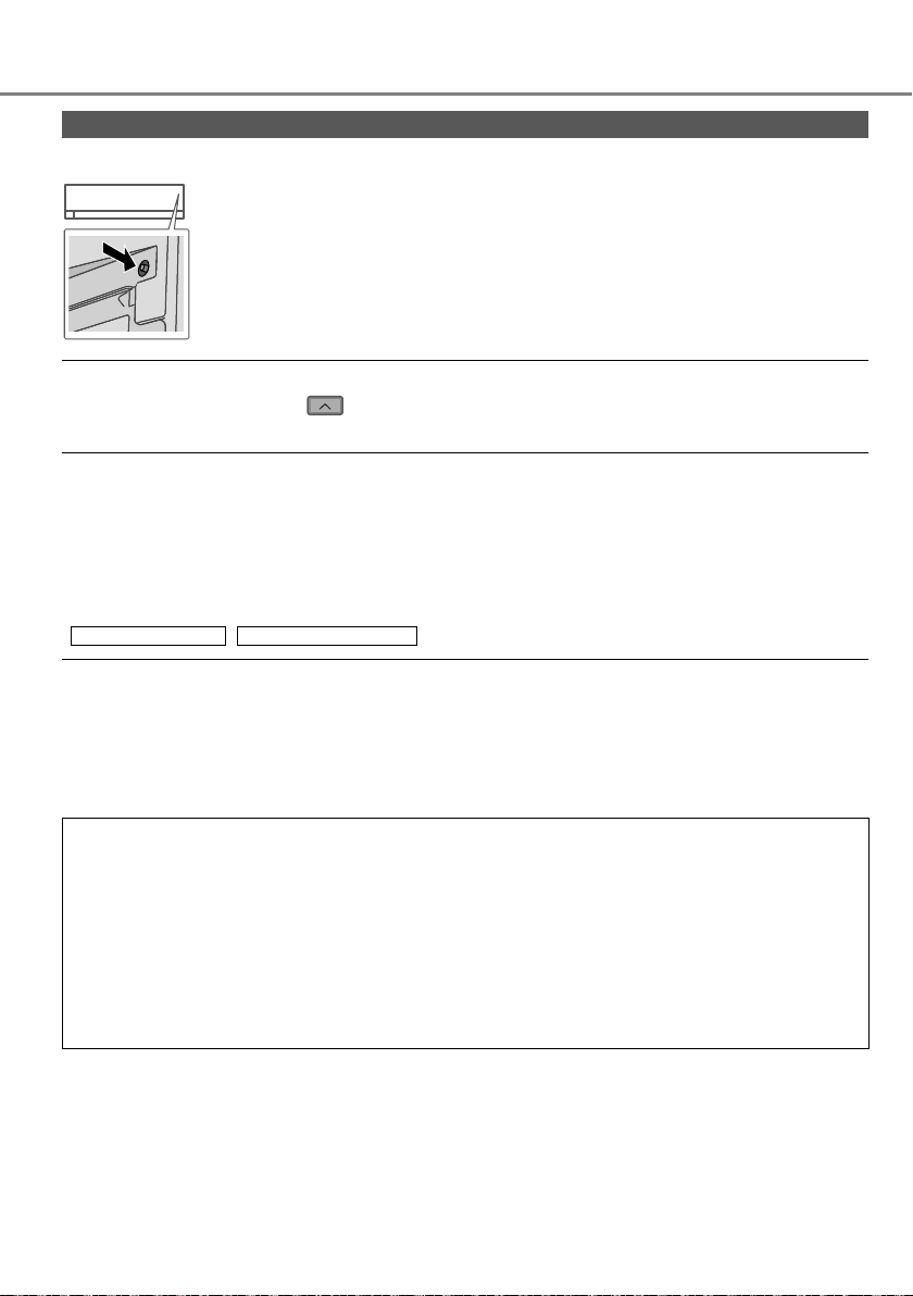
Localización de averías
Si…
■ El mando a distancia está extraviado o funciona mal
1.Abra el panel frontal.
2.Para usar en modo AUTOMÁTICO, pulse el botón una vez.
3. Pulse el botón y manténgalo pulsado hasta que oiga 1 pitido. A
continuación, suelte el botón para usar el modo FRÍO forzado.
4. Repita el paso 3. Pulse el botón y manténgalo pulsado hasta que oiga
2 pitidos. A continuación, suelte el botón para usar en el modo CALOR
forzado.
5.Vuelva a pulsar el botón para apagarlo.
■ Los indicadores brillan demasiado
• Pulse y mantenga pulsado durante 5 segundos para oscurecer o restablecer el brillo
del indicador de la unidad.
■ Se realiza una inspección estacional después de un largo periodo en desuso
• Inspeccione las pilas del mando a distancia.
• Compruebe que no haya ninguna obstrucción alrededor de las rejillas de entrada y salida
de aire.
Utilice el botón Auto OFF/ON (apagado/encendido automático) para seleccionar la operación
•
FRÍO/CALOR. Después de 15 minutos de funcionamiento, es normal tener la siguiente
diferencia de temperatura entre la ventilación del aire que ingresa y el aire que sale:
FRÍO: ≥ 8 °C / 14.4 °F CALOR: ≥ 14 °C / 25.2 °F
■ No se van a utilizar las unidades durante un periodo prolongado de tiempo
• Active el modo de CALOR durante 2 ~3 horas para retirar la humedad restante en todas las
partes internas y evitar así la acumulación de moho.
• Apague la unidad y desenchúfela.
• Extraiga las pilas del mando a distancia.
NO UTILICE LA UNIDAD SI
APAGUE LA FUENTE DE ALIMENTACIÓN Y DESENCHUFE, por favor consulte un
distribuidor autorizado en caso se verifi quen las siguientes condiciones:
• Si escucha ruidos extraños durante el funcionamiento.
• Si entra agua o elementos extraños en el mando a distancia.
• Si hay escapes de agua de la unidad interior.
• Si el interruptor del circuito salta frecuentemente.
• El cable de alimentación está demasiado caliente.
• Los interruptores o los botones no funcionan correctamente.
66
Page 67
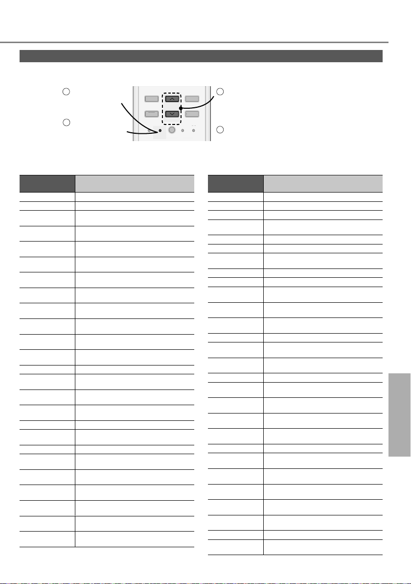
Cómo recuperar los códigos de error
TIMER
S
CANCEL
ON
O
S
K
RES
C
RC
Si la unidad se detiene y el indicador TIMER (TEMPORIZADOR) parpadea, utilice el mando a distancia
para recuperar el código de error.
Pulse durante
5 segundos
Pulse durante 5
3
segundos para
abandonar la
ON
TIMER
OFF
FF
SET CHECK CLOCK RESET
ET CLOC
SET
CANCEL
A
AC
ET
comprobación
•
Con determinados errores, puede reiniciar la unidad con el funcionamiento limitado si se escuchan 4
pitidos al ponerse en marcha la unidad.
Visualización de
diagnóstico
H 00 No hay memoria de fallo
H 11
H 12
H 14
H 15
H 16
H 17
H 19
H 21
H 23
H 24
H 25
H 26
H 27
H 28
H 30
H 31 Anomalía en el sensor de piscina
H 32
H 33 Anomalía en la conexión interior/exterior
H 34
H 35
H 36
H 37
H 38
H 39
*
Es posible que algún código de error no se aplique a su modelo. Consulte a un distribuidor autorizado para
Anomalía/Control de protección
Comunicación anómala interior/exterior
Capacidad de unidad interior
incomparable
Anomalía en el sensor de temperatura
de entrada interior
Anomalía en el sensor de temperatura
del compresor exterior
Anomalía en el transformador de
corriente exterior (CT)
Anomalía en el sensor de temperatura
de aspiración exterior
Bloqueo del mecanismo del motor del
ventilador interior
Anomalía en el funcionamiento del
interruptor interior de fl otador
Anomalía en el sensor de temperatura 1
del intercambiador de calor interior
Anomalía en el sensor de temperatura 2
del intercambiador de calor interior
Anomalía en el dispositivo de iones
interior
Anomalía de iones negativos
Anomalía en el sensor de temperatura
de aire exterior
Anomalía en el sensor de temperatura 1
del intercambiador de calor exterior
Anomalía en el sensor de temperatura
de descarga exterior
Anomalía en el sensor de temperatura 2
del intercambiador de calor exterior
Anomalía en el sensor de temperatura
del disipador de calor exterior
Anomalía en la contracorriente de agua
interior/exterior
Anomalía en el sensor de temperatura
de la tubería de gas exterior
Anomalía en el sensor de temperatura
de la tubería de líquido exterior
Discrepancia interior/exterior (código de
marca)
Anomalía en unidad en funcionamiento o
unidades en espera interiores
cualquier aclaración.
ET
RC
Visualización de
diagnóstico
21
Pulse hasta escuchar un
pitido y, después, apunte el
código del error
4
Apague la unidad y comunique el
código de error a un distribuidor
autorizado
Anomalía/Control de protección
H 41
H 50 Motor de ventilador bloqueado
H 51 Motor de ventilador bloqueado
H 52
H 58 Anomalía de sensor de gas interior
H 59 Anomalía del sensor Eco
H 64
H 67 Anomalía en nanoe
H 70 Anomalía en el sensor de luz
H 71
H 72
H 97
H 98 Protección de alta presión interior
H 99
F 11
F 16
F 17
F 18
F 87
F 90
F 91 Anomalía en el ciclo de refrigeración
F 93
F 94
F 95
F 96
F 97
F 98
F 99
Anomalía en conexión de cables o tuberías
Anomalía de fi jación de interruptor de
límite izquierdo-derecho
Anomalía en el sensor exterior de alta
presión
Anomalía en la tarjeta de control interior
del ventilador de CC
Anomalía del sensor de temperatura del
acumulador
Bloqueo del mecanismo del motor del
ventilador exterior
Protección antecongelante de unidad de
funcionamiento interior
Anomalía de conmutación de la válvula
de 4 vías
Protección total de corriente en circulación
Anomalía de congelación de unidades
interiores en espera
Anomalía de circuito de
deshumidificación bloqueado
Protección de sobrecalentamiento de
caja de control
Protección de la Corrección de factor
energético (PFC)
Anomalía de revoluciones del
compresor exterior
Protección de exceso de presión de la
descarga del compresor
Protección de alta presión de
refrigeración exterior
Protección de sobrecalentamiento del
módulo de transistor de alimentación
Protección de sobrecalentamiento del
compresor
Protección total de corriente en circulación
Detección de pico de corriente directa
(CD) exterior
Localización de averías
Español
67
Page 68

Information
English
Information for Users on Collection and Disposal of Old Equipment and Used
Batteries
These symbols on the products, packaging, and/or accompanying documents
mean that used electrical and electronic products and batteries should not be
mixed with general household waste.
For proper treatment, recovery and recycling of old products and used batteries,
please take them to applicable collection points, in accordance with your national
legislation.
By disposing of these products and batteries correctly, you will help to save
valuable resources and prevent any potential negative effects on human health
and the environment which could otherwise arise from inappropriate waste
handling.
For more information about collection and recycling of old products and batteries,
please contact your local municipality, your waste disposal service or the point of
sale where you purchased the items.
Penalties may be applicable for incorrect disposal of this waste, in accordance
with national legislation.
For business users in the European Union
If you wish to discard electrical and electronic equipment, please contact your
dealer or supplier for further information.
[Information on Disposal in other Countries outside the European Union]
These symbols are only valid in the European Union. If you wish to discard these
items, please contact your local authorities or dealer and ask for the correct
method of disposal.
Pb
Note for the battery symbol (bottom two symbol examples):
This symbol might be used in combination with a chemical symbol. In this case it
complies with the requirement set by the Directive for the chemical involved.
68
WARNING
This symbol shows that
this equipment uses a
fl ammable refrigerant. If
the refrigerant is leaked,
together with an external
ignition source, there is a
possibility of ignition.
This symbol shows that a
service personnel should be
handling this equipment with
reference to the Installation
Instructions.
This symbol shows that
the Operation Instructions
should be read carefully.
This symbol shows that
there is information included
in the Operation Instructions
and/or Installation
Instructions.
Page 69
Informations
Français
Avis aux utilisateurs concernant la collecte et l’élimination des piles et des appareils
électriques et électroniques usagés
Apposé sur le produit lui-même, sur son emballage, ou fi gurant dans la
documentation qui l’accompagne, ce pictogramme indique que les piles et
appareils électriques et électroniques usagés doivent être séparés des ordures
ménagères.
Afi n de permettre le traitement, la valorisation et le recyclage adéquats des piles
et des appareils usagés, veuillez les porter à l’un des points de collecte prévus,
conformément à la législation nationale en vigueur.
En éliminant piles et appareils usagés conformément à la réglementation en
vigueur, vous contribuez à prévenir le gaspillage de ressources précieuses
ainsi qu’à protéger la santé humaine et l’environnement contre les effets
potentiellement nocifs d’une manipulation inappropriée des déchets.
Pour de plus amples renseignements sur la collecte et le recyclage des piles et
appareils usagés, veuillez vous renseigner auprès de votre mairie, du service
municipal d’enlèvement des déchets ou du point de vente où vous avez acheté
les articles concernés.
Le non-respect de la réglementation relative à l’élimination des déchets est
passible d’une peine d’amende.
Pour les utilisateurs professionnels au sein de l’Union européenne
Si vous souhaitez vous défaire de pièces d’équipement électrique ou
électronique, veuillez vous renseigner directement auprès de votre détaillant ou
de votre fournisseur.
[Information relative à l’élimination des déchets dans les pays extérieurs à
l’Union européenne]
Ce pictogramme n’est valide qu’à l’intérieur de l’Union européenne. Pour
connaître la procédure applicable dans les pays hors Union Européenne,
Pb
veuillez vous renseigner auprès des autorités locales compétentes ou de votre
distributeur.
Note relative au pictogramme à apposer sur les piles (voir les 2 exemples
ci-contre) :
Le pictogramme représentant une poubelle sur roues barrée d’une croix est
conforme à la réglementation. Si ce pictogramme est combiné avec un symbole
chimique, il remplit également les exigences posées par la Directive relative au
produit chimique concerné.
Ce symbole indique que cet
équipement utilise un réfrigérant
infl ammable. Il existe un risque
AVERTISSEMENT
d’infl ammation en cas de fuite
du réfrigérant en présence d’une
source d’infl ammation externe.
Ce symbole indique qu’un
personnel d’entretien doit
manipuler cet équipement en se
référant au manuel d’installation.
Ce symbole indique que le
manuel d’instruction doit être lu
attentivement.
Ce symbole indique que certaines
informations sont incluses dans le
manuel d’utilisation et/ou manuel
d’installation.
69
Page 70
Información
Español
Información para Usuarios sobre la Recolección y Eliminación de aparatos viejos y
baterías usadas
Estos símbolos en los productos, embalajes y/o documentos adjuntos, signifi can
que los aparatos eléctricos y electrónicos y las baterías no deberían ser
mezclados con los desechos domésticos.
Para el adecuado tratamiento, recuperación y reciclaje de los productos viejos
y pilas y baterías usadas llévelos a los puntos de recogida de acuerdo con su
legislación nacional.
Al desechar estos aparatos y baterías correctamente, Usted estará ayudando
a preservar recursos valiosos y a prevenir cualquier potencial efecto negativo
sobre la salud de la humanidad y el medio ambiente que, de lo contrario, podría
surgir de un manejo inapropiado de los residuos.
Para mayor información sobre la recuperación y el reciclado de aparatos y
baterías viejas, por favor, contacte con su comunidad local, su servicio de
eliminación de residuos o al comercio donde adquirió estos aparatos.
Podrán aplicarse penas por la eliminación incorrecta de estos residuos, de
acuerdo a la legislación nacional.
Para usuarios empresariales en la Unión Europea
Si usted desea desechar aparatos eléctricos y electrónicos, por favor contacte
con su distribuidor o proveedor a fi n de obtener mayor información.
[Informacion sobre la Eliminación en otros Países fuera de la Unión
Europea]
Estos símbolos sólo son válidos dentro de la Unión Europea. Si desea desechar
estos objetos, por favor contacte con sus autoridades locales o distribuidor y
consulte por el método correcto de eliminación.
Pb
Nota sobre el símbolo de la bateria (abajo, dos ejemplos de símbolos):
Este símbolo puede ser usado en combinación con un símbolo químico. En este
caso, el mismo cumple con los requerimientos establecidos por la Directiva para
los productos químicos involucrados.
ADVERTENCIA
70
Este símbolo indica que el equipo
utiliza un refrigerante infl amable.
Si se produce una fuga de
refrigerante unida a una fuente
externa de ignición, existe peligro
de ignición.
Este símbolo indica que el manejo
de este equipo en relación con
las Instrucciones de instalación
debe ser realizado por personal de
servicio técnico.
Este símbolo indica que deben
leerse detenidamente las
Instrucciones de funcionamiento.
Este símbolo indica que las
Instrucciones de funcionamiento
y/o las Instrucciones de instalación
contienen información adicional.
Page 71

Memo
71
Page 72

Panasonic Corporation
1006 Kadoma, Kadoma City,
Osaka, Japan
Website: http://www.panasonic.com
© Panasonic Corporation 2018
Printed in Malaysia
Authorised representative in EU
Panasonic Testing Centre
Panasonic Marketing Europe GmbH
Winsbergring 15, 22525 Hamburg, Germany
ACXF55-18840
PC0218-0
 Loading...