

Page 1
Order No. MAC0502037C2
Air Conditioner
CS-F50DB4E5 CU-L50DBE8
CONTENTS
Page Page
1 Service Information 3
1.1. Example of trouble at test operation
1.2. Caution of test operation
1.3. Caution during automatic address setting
3
3
3
1.4. Operation range 4
2 Features
2.1. Variety of excellent features
2.2. Low-noise outdoor units
© 2005 Panasonic HA Air-Conditioning (M) Sdn Bhd
(11969-T). All rights reserved. Unauthorized copying
and distribution is a violation of law.
5
5
7
Page 2
CS-F50DB4E5 CU-L50DBE8
2.3. Improved workability 8
2.4. A brand-new control method
2.5. Wired Remote Control
2.6. Wireless Remote Control
2.7. Group Control Equipment
3 Specification
3.1. Product Specification
4 Dimensions
4.1. CS-F50DB4E5
4.2. CU-L50DBE8
5 Refrigeration Cycle
6 Block Diagram
6.1. CS-F50DB4E5
6.2. CU-L50DBE8
7 Wiring Diagram
7.1. CS-F50DB4E5
7.2. CU-L50DBE8
8 Operation Details
8.1. Wired Remote Control (Optional part)
8.2. Wireless Remote Control (Optional part)
9 Operation Control
9.1. Operation Mode
9.2. Compressor Start Control
9.3. Cooling Operation
9.4. Heating Mode Operation
9.5. Louver Control
9.6. Odour Removing Operation
9.7. Energy Save Operation
9.8. Outdoor Fan Remaining Heat Removal Control
9.9. Crank Case Heater Control
9.10. Valve Error
9.11. Pump Down Operation
9
10
10
11
12
12
13
13
14
15
16
16
17
18
18
19
20
20
21
22
22
22
22
25
28
30
31
31
31
9.12. Indoor Air Volume Up Control (DC Fan Motor Type Only)
10 Installation Instruction
10.1. Pipe length
10.2. Refrigerant additional charge
10.3. Position of the centre gravity
10.4. Indoor unit installation
10.5. Outdoor unit installation
10.6. Wired remote control installation
10.7. Wireless remote control installation manual
10.8. Twin
11 Installation and Servicing Air Conditioner Using R410A
11.1. Outline
11.2. Tools for installing/servicing refrigerant piping
11.3. Refrigerant piping work
11.4. Installation, transferring, servicing
12 Troubleshooting Guide
12.1. Self-diagnosis error code table
13 Servicing Information
13.1. Caution when servicing of fan and fan motor
14 Replacement Parts
14.1. Indoor unit
14.2. Outdoor unit
15 Electronic Circuit Diagram
15.1. Indoor unit
15.2. Outdoor unit
15.3. Wired remote control
15.4. Wireless remote control
15.5. Print pattern
31
32
32
33
33
34
34
35
47
58
65
72
73
73
74
78
80
84
84
86
86
87
87
92
96
96
100
105
106
107
2
Page 3

CS-F50DB4E5 CU-L50DBE8
1 Service Information
Notice of Address setting for NEW Cassette / NEW Outdoor Unit.
The new Cassette / New Outdoor models are possible to have address setting for twin control by automatic when main
power supply is switched on.
(Manual address setting is also possible by using Dip switch on Indoor unit P.C. board.) However,
possible when made proper wiring connection and also Indoor unit should be original virgin unit
1.1. Example of trouble at test operation
If found out as following phenomenon at test operation on site, it may have possibility of wrong address setting.
Therefore, please ensure of the address setting.
1. LCD display of wired remote control had not illuminate although the main power supply switch is ‘on’.
2. LCD display had indicate d as normal illumination when power supply switch is ‘on’, however outdoor unit cannot be operated.
(But, it is necessary to take 3 to 5 minutes for outdoor unit to start from the timing of remote control ON/OFF switch is ‘on’.)
3. P.C. board had memorized wrong setting information.
a. If main power supply is switched ‘on’ with the wrong connection.
b. When changing the connection or combination of units due to re-installation etc.
•
•
When changing the system from twin control to normal one to one system.
• •
•
•
When making the replacement of units as master and slave etc.
• •
this address setting is only
.
1.2. Caution of test operation
Do not touch the remote control switch and do not change any wirings for one minute when the main power supply switch is ‘on’.
(Because the unit is having automatic address setting during the first one minute.)
1.3. Caution during automatic address setting
When main power supply switch is ‘on’, the P.C. board will automatically memorized the connecting system.
Consequently, when initial power supply is ‘on’, there will not be interchangeability of units even of the same type and same
capacity unit. Therefore unable to connect the unit to another system.
3
Page 4
CS-F50DB4E5 CU-L50DBE8
1.4. Operation range
1.4.1. Power Supply
The applicable voltage range for each unit is given in the following table. The working voltage among the three phases must be
balanced within a 3% deviation from each voltage at the compressor terminals. The starting voltage must be higher than 85% of
the rated voltage.
MODEL Unit Main Power Applicable Voltage
CU- Phase, Volts Hz Max Min
L34DBE5 1~240 50 264 216
L43DBE5 1~220 50 242 198
1~230 50 253 207
L50DBE8 3N~380 50 418 342
3N~400 50 440 360
3N~415 50 457 374
1.4.2. Indoor and Outdoor Temperature
•
•
Model 50Hz CU-L34DBE5, CU-L43DBE5, CU-L50DBE8
• •
Operating Hz Indoor Temp. (D.B./W.B.) (°C) Outdoor Temp. (D.B./W.B.) (°C)
Max Min Max Min
Cooling 50 32/23 21/15 43/- -15/Heating 50 27/- 16/- 24/18 -20/-
4
Page 5
2 Features
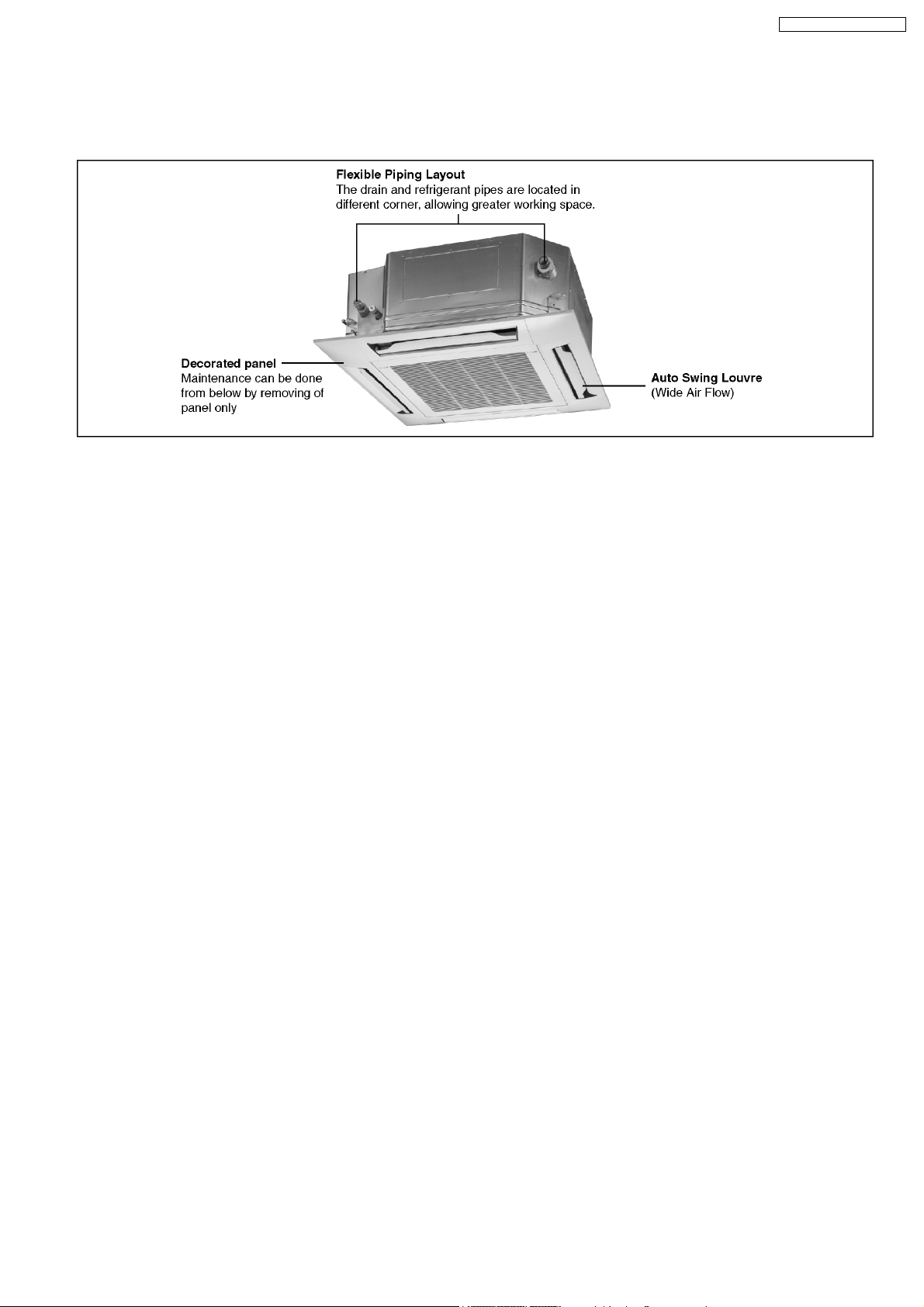
2.1. Variety of excellent features
CS-F50DB4E5 CU-L50DBE8
2.1.1. Compact design
•
•
The height is only 288 mm and can be installed even where the space is limited.
• •
2.1.2. Automatic restart function
•
•
When the electric power comes back after a power failure, the unit itself automatically restarts the operation in the pre-failure
• •
mode.
2.1.3. Auto fan mode (indoor unit)
•
•
Auto fan mode is added besides Hi, Me and Lo.
• •
It automatically adjusts the fan speed according to the indoor temperature.
2.1.4. Dry mode function
•
•
Dry mode can make a comfortable indoor environment during wet season.
• •
2.1.5. Quiet operation
•
•
The sound level is as low as 42 dB (A) for model CS-F50DB4E5 and suitable for offices, shops, homes etc., where quiet
• •
operation is essential.
2.1.6. Auto Swing Louvre
•
•
The air flow angle can be changed automatically (or manually) to an angle between 10° to 70° using the remote control.
• •
2.1.7. Low ambient cooling operation
•
•
Cooling operation is possible at outdoor temperature of -5°C.
• •
5
Page 6

CS-F50DB4E5 CU-L50DBE8
2.1.8. Piping and drainage
•
•
Built-in upward draining mechanism.
• •
2.1.9. Automatic changeover function (heat pump models)
•
•
The unit automatically switches between cooling and heating in accordance with operating load in order to maintain a
• •
comfortable indoor temperature.
2.1.10. Hot start system (heat pump models)
6
Page 7
2.2. Low-noise outdoor units
CS-F50DB4E5 CU-L50DBE8
[Product features]
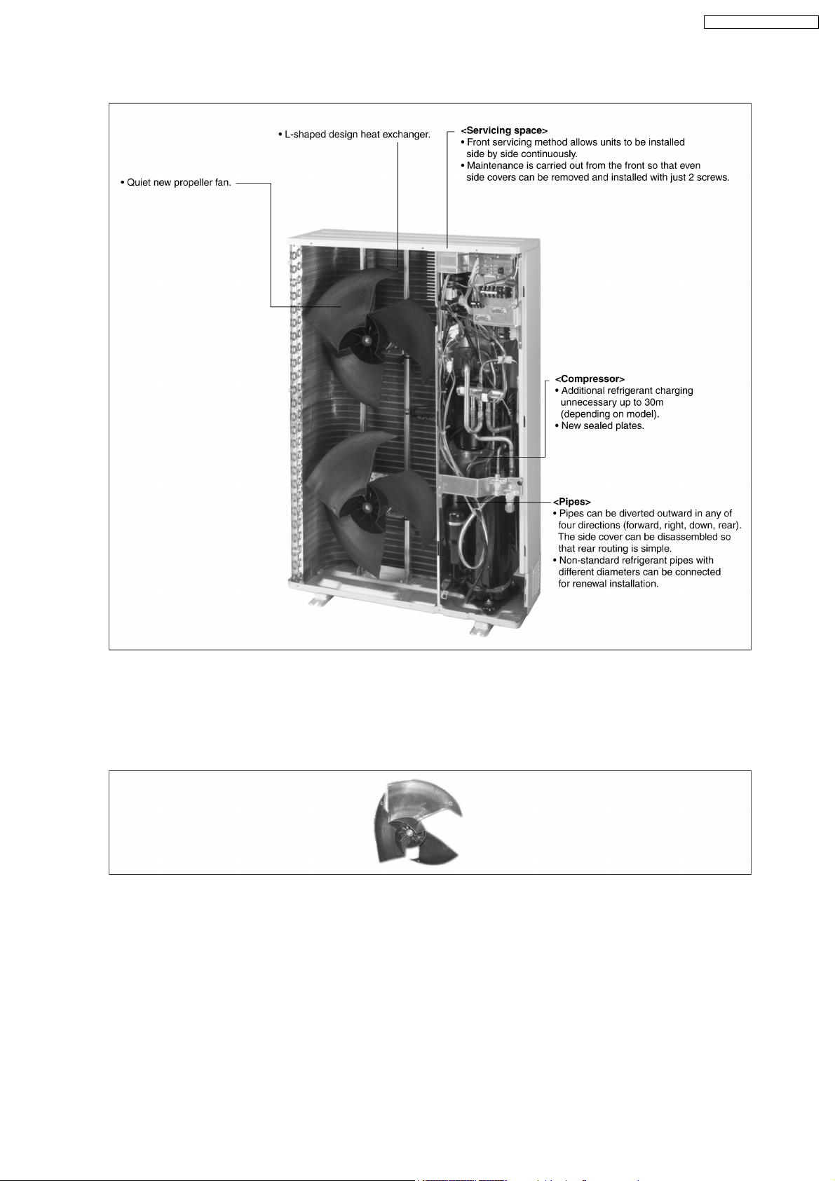
2.2.1. Low-noise design improves in surrounding areas
1. The noise-suppressing winglet fan is a result of new research into vane design theory. The unique curved shape suppresses
the generation of vortexes, thus reduces air flow noise.
2. The adoption of double-orifice rings reduces air passage resistance.
3. Strengthening of the noise insulation materials in the compressor and the sealing-in of mechanical noise allows vibration noise
to be greatly enclosed and suppressed.
4. The heat exchanger has an L-shaped design to allow air to flow more smoothly.
5. Noise is automatically reduced further during night time operation with lower outdoor air temperatures.
7
Page 8
CS-F50DB4E5 CU-L50DBE8
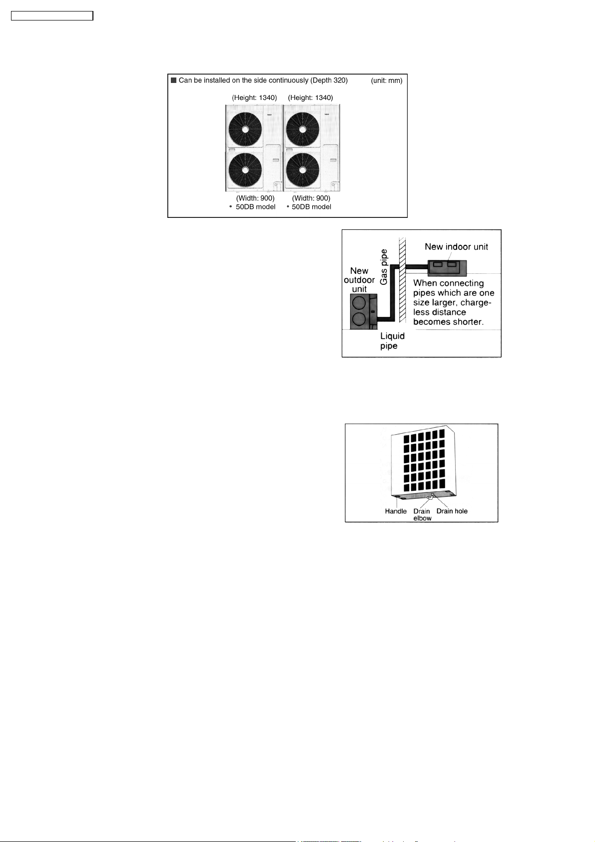
2.3. Improved workability
2.3.1. Pipes that are one size larger can
also be connected for renewal
•
•
If renewing the system, existing refrigerant pipes can be
• •
utilized so that only the indoor units need to be replaced.
•
•
For example, liquid and gas pipes from 10 years ago can be
• •
connected to current pipes with the same size for one size
larger. Effective utilization of materials reduces working
time and trouble. (Adaptor sockets are not supplied.)
2.3.2. Additional refrigerant charging
•
•
All models do not require any additional charging of refrigerant for 30m of pipe length. This makes installation much easier.
• •
2.3.3. Drain water dripping-prevention
structure
•
•
The base of the outdoor unit is provided with a single drain
• •
hole in order to prevent drain water from leaking out of the
unit. Body connecting a drain elbow and a discharge pipe,
water leakages can be prevented even when the unit is
installed against a wall.
2.3.4. Space saving design allows units to be installed side by side continuously
•
•
Servicing after installation can be carried-out by removing the front covers.
• •
2.3.5. Easy test operation
•
•
Test operation can be carried out for both indoor and outdoor units.
• •
2.3.6. Long pipe design
•
•
Maximum piping length of 50m.
• •
2.3.7. Internal pipe connection
•
•
Pipes are connected inside the units (inside the side covers), making the final appearance more attractive.
• •
•
•
Pipes can be diverted outward in any of four directions (forward, right, down, rear).
• •
•
•
Small liquid pipe diameters of 9.53mm, making installation work much easier.
• •
8
Page 9
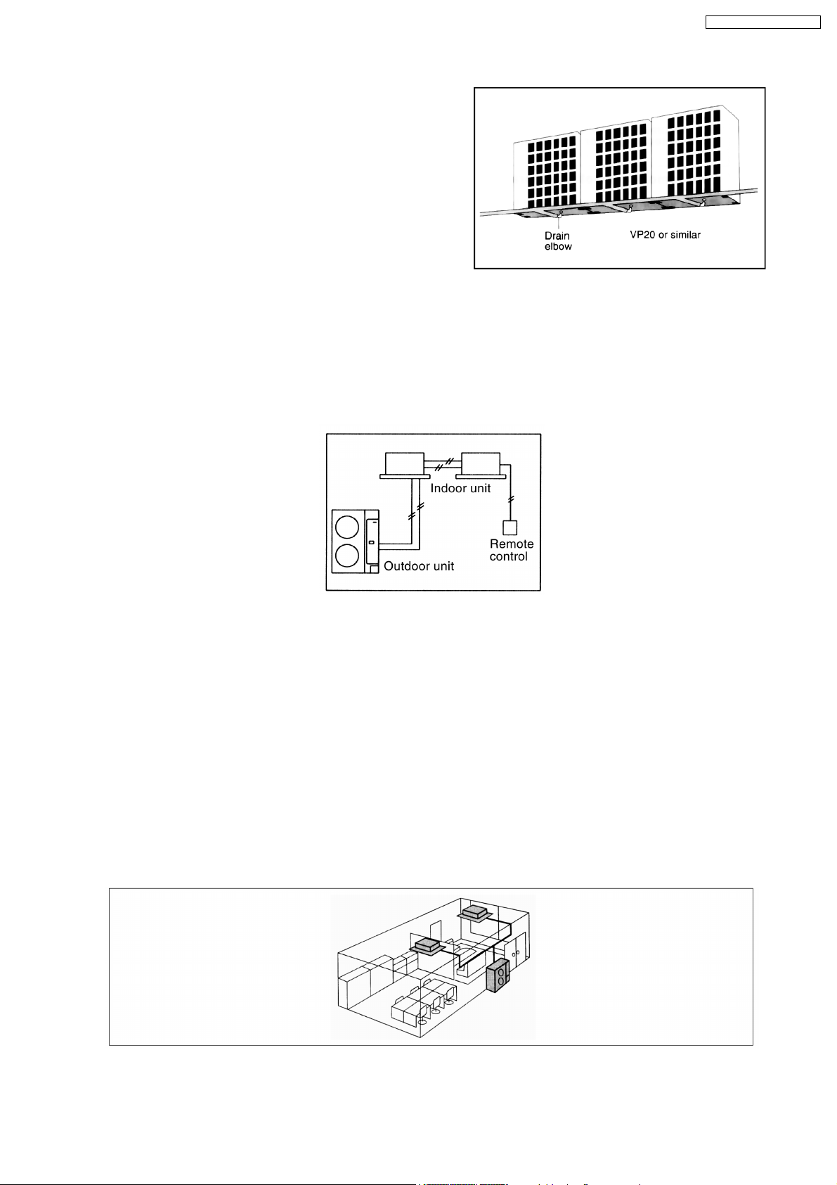
2.3.8. Centralized draining method
•
•
Even when multiple outdoor units are installed to a wall, the
• •
drain outlets can be concentrated into a single drain pipe.
This makes installation easier and also improve
appearance.
2.4. A brand-new control method
Easier power supply wiring connec tion
1.
Power supply wiring and other wiring tasks can be carried out more easily.
•
•
Twin non-polar wires used to connect indoor and outdoor units.
• •
•
•
Adoption of connection error prevention circuits for drive wires and signal wires. If a connection error is made, the relay does
• •
not operate and current does not flow to the circuit boards.
CS-F50DB4E5 CU-L50DBE8
Twin operation
2.
•
•
Simultaneous air conditioning of wide spaces and corners is possible. Indoor units of same horsepowers can even be used
• •
in combination.
•
•
Master unit and slave-units can be set automatically in twin systems. No address setting is necessary.
• •
•
•
Multiple indoor units can be operated simultaneously with a single remote control. Note that individual operation is not
• •
possible.
Separate indoor/outdoor unit power supplies
3.
The power supply can be connected to (1) just the outdoor units, or (2) to both the indoor and outdoor units.
Easy test operation
4.
Test operation can be carried out for both indoor and outdoor units.
Automatic setting initialization function
5.
In accordance with the indoor and outdoor units connected and the connection methods, conditions such as the connection
configuration (twin format) and remote-control functions such as automatic louvre operation and cooling or heating mode are
automatically detected and set instantly.
(Remote control and Indoor unit)
9
Page 10
CS-F50DB4E5 CU-L50DBE8
2.5. Wired Remote Control
1. The new design includes an easily-visible red pilot lamp. The power can be turned on and off at a single touch, without opening
the cover.
2. Has a build-in thermistor, allowing indoor temperature detection in accordance with indoor conditions by switching with main unit
thermistor.
3. Twin non-polar wires make installation work easy. (10 m cable supplied as accessory.)
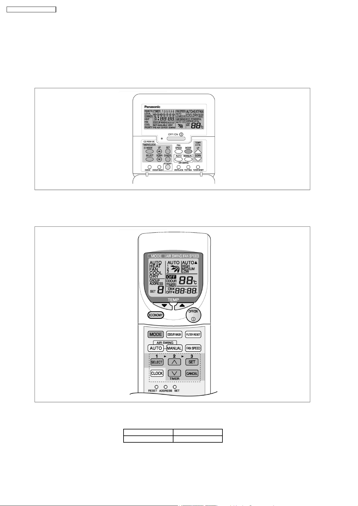
2.6. Wireless Remote Control
1. New design with compact size. (Operation range within approximately 8 m.)
2. Built-in timer with OFF/ON timer setting (within 24 hours)
Wired Wireless
CZ-RD513C CZ-RL513B
NOTE: Both of the above remote control is packed separately from the indoor unit.
10
Page 11
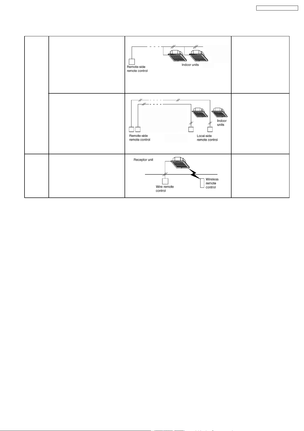
2.7. Group Control Equipment
CS-F50DB4E5 CU-L50DBE8
Wired
remote
control
Common
control
Group control by one remote
control
•
•
All air conditioner units are
• •
controlled as a whole by remote
control.
•
•
All indoor units operate in the
• •
same mode.
•
•
A maximum of 16 units can be
• •
connected together (sequental
starting)
Twin remote control separate
control
•
•
Each indoor unit can be operated
• •
by either one of the two remote
control.
•
•
Apart from timer setting time,
• •
displays for two remote control are
identical.
•
•
Last button pressed has priority
• •
(main or slave is set at remote
control unit).
Common control / group
•
•
Operation is possible using either
• •
wired or wireless remote control
unit.
•
•
Last button pressed has priority.
• •
[Remote side]
•
•
Optional wired remote
• •
control CZ-RD513C
[Local side]
Not needed
[Remote side]
•
•
Optional wired remote
• •
control
[Local side]
•
•
Optional wired remote
• •
control CZ-RD513C
•
•
Optional wired remote
• •
control and wireless
remote control
Wired CZ-RD513C
Wireless CZ-RL513B
11
Page 12
CS-F50DB4E5 CU-L50DBE8
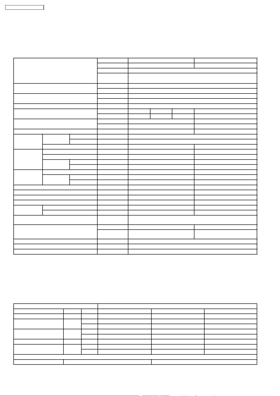
3 Specification
3.1. Product Specification
3.1.1. CS-F50DB4E5 CU-L50DBE8
ITEM / MODEL Indoor Unit Outdoor Unit
Main Body CS-F50DB4E5 CU-L50DBE8
Panel CZ-BT03P
Remote CZ-RD513C (Wired)
Control CZ-RL513B (Wireless)
Cooling Capacity kW 14.0
BTU/h 47,700
Heating Capacity kW 16.0
BTU/h 54,600
Refrigerant Charge-less m 30
Standard Air Volume for High, m3/min Hi 32 Me 29 Lo 25 Hi 98
Medium and Low Speed cfm 1130 970 850 3460
Outside Dimension (H x W x D) mm 288 x 840 x 840 1340 x 900 x 320
inch 11-11/32 x 33-1/24 x 33-1/24 52-7/8 x 35-7/16 x 12-19/32
Net Weight kg (lbs) 28.5 (63) 105 (231)
Piping
Connection
Compressor Type, Number of Set - Hermetic - 2P (Rotary), 2
Fan Type, Number of Set Turbo fan-1 Propeller fan-1
Air-heat Exchanger (Row x Stage x FPI) Louver-fin type (2 x 12 x 21) Corrugate-fin type (2 x 51 x 18)
Refrigerant Control - Exp. Value
Refrigerant Oil (Charged) cm
Refrigerant (Charged) R410A kg (oz) - 3.50 (123)
Running
Adjustment
Safety Devices Internal protector for compressor, Internal thermostat for fan motor,
Noise Level dB (A) Hi 47 Lo 42 Cooling 54, Heating 56
Moisture Removal L/h 9.0
EER W/W 3.01
COP W/W 3.41
Refrigerant Gas mm (inch) O.D Ø 15.88 (5/8) Flared Type
Liquid mm (inch) O.D Ø 9.53 (3/8) Flared Type
Drain mm O.DØ20 I.D Ø 20 x 1
Starting Method - DC-INV control
Motor Type - 4-pole single phase brushless motor
Rated Output kW - 3.8
Motor Type 8-pole DC brushless motor 6-pole single phase induction motor
Rated Output kW 0.06 0.07 x 2
3
Control Switch Wireless or Wired Remote Control Room Temperature Thermostat -
Crankcase heater, High pressure switch, Current transformer
Power level dB Cooling : Hi 62 Lo 57
Heating : Hi 62 Lo 57
- FV50S (1200)
Cooling 68, Heating 70
1. Cooling capacities are based on indoor temperature of 27°C D.B. (80.6°F D.B.), 19.0°C W.B. (66.2°F W.B.) and outdoor air
temperature of 35°C D.B. (95°F D.B.), 24°C W.B. (75.2°F W.B.)
2. Heating capacities are based on indoor temperature of 20°C D.B. (68°F D.B.) and outdoor air temperature of 7°C D.B. (44.6°F
D.B.), 6°C W.B. (42.8°F W.B.)
ELECTRICAL DATA (50 Hz)
ITEM / MODEL Condition by JIS-B8615
Volts V 380 400 415
Phase 3N 3N 3N
Power Consumption kW Cool 4.65 4.65 4.65
Heat 4.69 4.69 4.69
Running Current A Cool 7.30 7.1 7.0
Heat 7.4 7.2 7.1
Starting Current A 7.4 7.2 7.1
Power Factor % Cool 97 95 92
Heat 96 94 92
*Power Factor means total figure of compressor, indoor fan motor and outdoor fan motor.
Panasonic Power source AC, 3N~380V, 400V, 415V 50Hz
12
Page 13
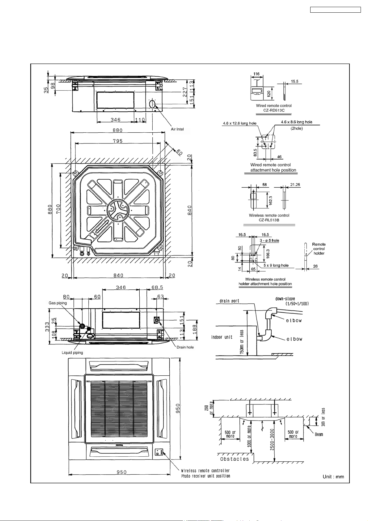
4 Dimensions
4.1. CS-F50DB4E5
CS-F50DB4E5 CU-L50DBE8
13
Page 14
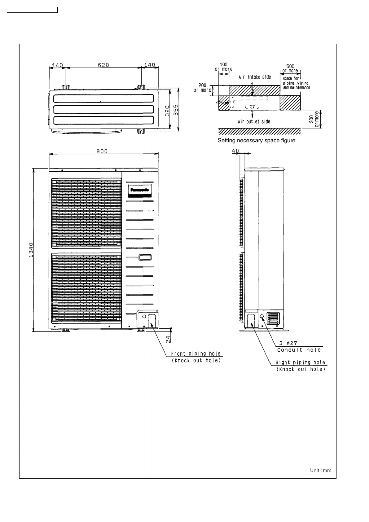
CS-F50DB4E5 CU-L50DBE8
4.2. CU-L50DBE8
14
Page 15
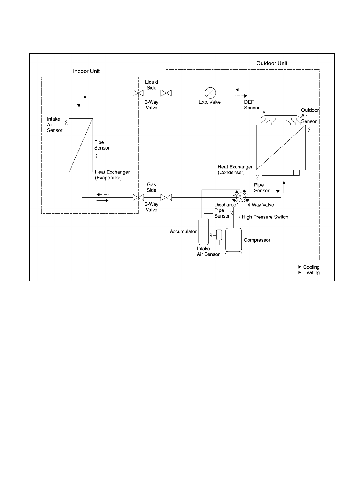
5 Refrigeration Cycle
CS-F50DB4E5 CU-L50DBE8
15
Page 16
CS-F50DB4E5 CU-L50DBE8
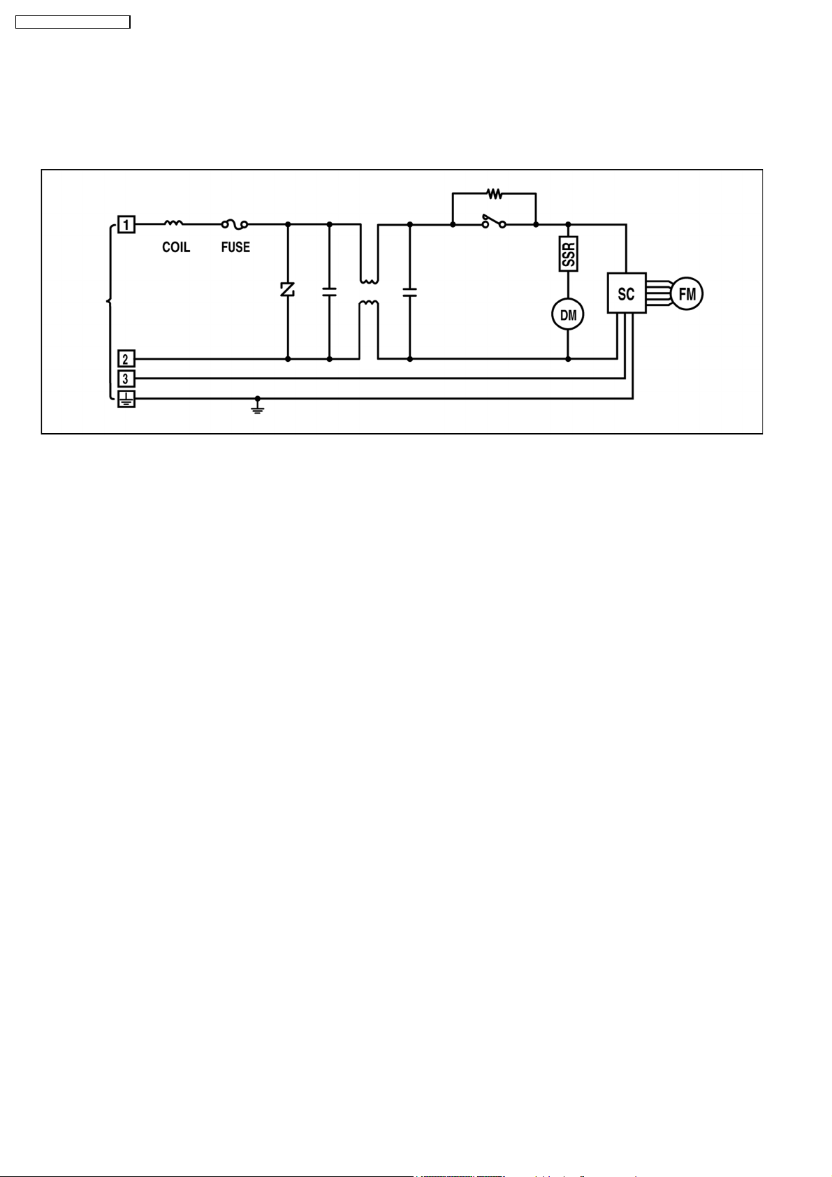
6 Block Diagram
6.1. CS-F50DB4E5
16
Page 17
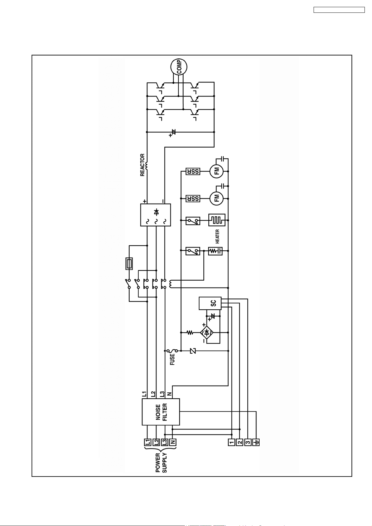
6.2. CU-L50DBE8
CS-F50DB4E5 CU-L50DBE8
17
Page 18
CS-F50DB4E5 CU-L50DBE8
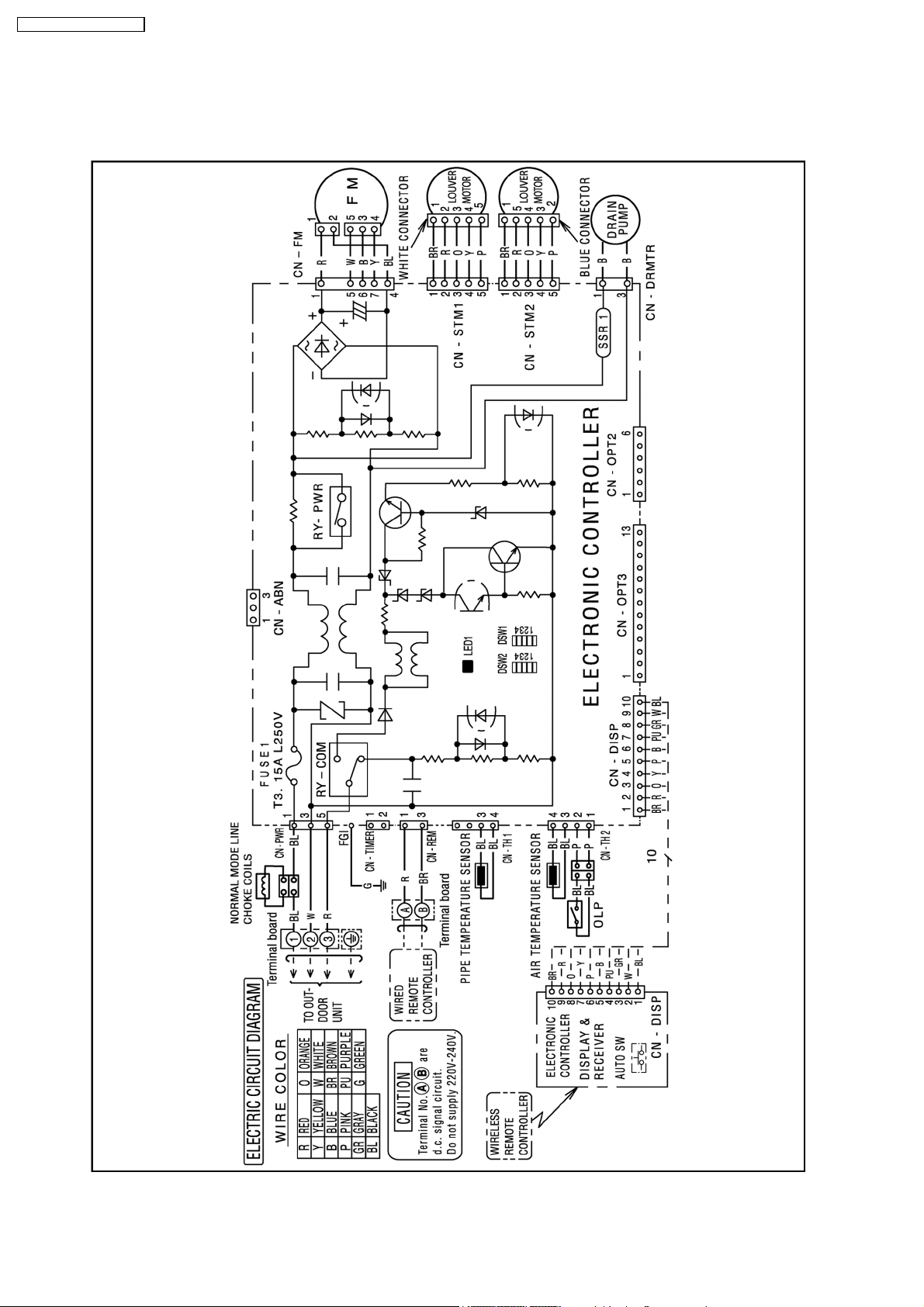
7 Wiring Diagram
7.1. CS-F50DB4E5
18
Page 19
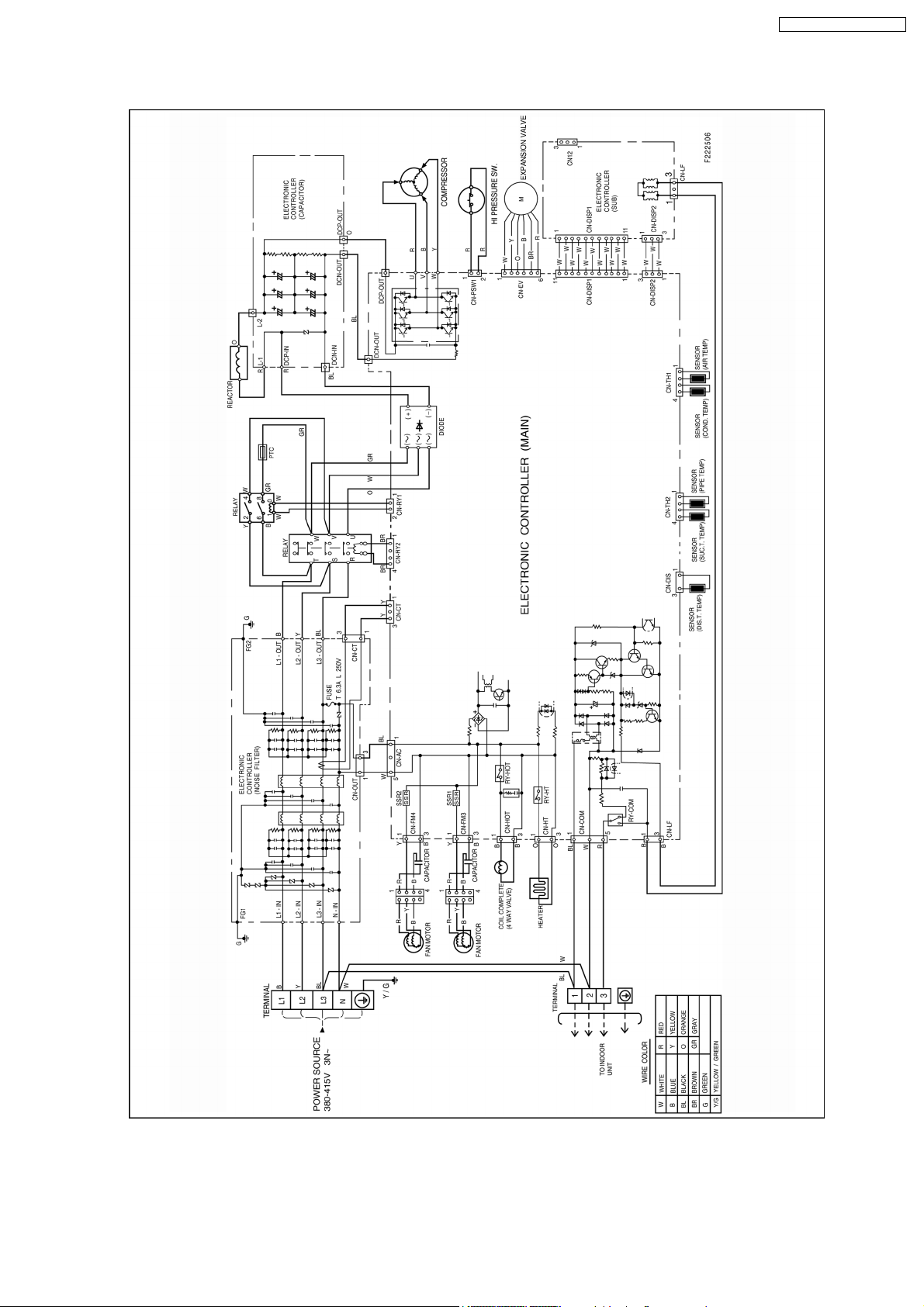
7.2. CU-L50DBE8
CS-F50DB4E5 CU-L50DBE8
19
Page 20
CS-F50DB4E5 CU-L50DBE8
8 Operation Details
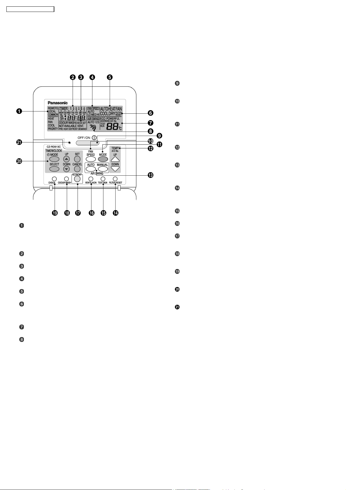
8.1. Wired Remote Control (Optional part)
Name and function of each part
OFF/ON button
Used to start and stop the operation.
FAN SPEED button
Used to select the fan speed of high (HI), medium (MED), low
(LO) or auto (AUTO).
MODE button
Used to select the operation of AUTO, HEAT, FAN, COOL, or
DRY.
TEMP (UP/DOWN) buttons
Used to select the desired temperature.
AIR SWING (AUTO/MANUAL) buttons
Used to determined the air swing condition, either auto or
manual.
REMOTE
The OFF/ON button cannot be used.
LOCAL
All wired remote control buttons can be used.
Time/time setting display
Check display
Fan speed display
Operation mode selection display
FILTER RESET display
(Appears after the cumulative running time reaches
approximately 2,500 hours of operation.)
Temperature setting display (16°C - 31°C)
Airflow direction setting display
FILTER RESET button
Press to reset the “FILTER RESET” display after washing the
filter.
TEST RUN button*
VENTILATION button*
ECONOMY operation button
Provides Energy saving function
ODOUR WASH button
Provides deodorizing function.
CHECK button
Press this button if the check display is flashing.
TIMER/CLOCK SET buttons
Used to set the timer operation and the current time.
Operation indicator
Lights up when the unit in operation.
NOTES
•
•
Ensure that the correct button is pressed as simultaneous pressing of the multiple buttons will not make the setting correct.
• •
•
•
The illustration above is for explanatory purposes only. The appearance will be different during actual operation.
• •
•
•
Do not operate the remote control with wet hands. Otherwise, electric shock or malfunction may occur.
• •
•
•
Do not press the remote control buttons with sharp object as this may damage the remote control.
• •
•
•
Buttons marked with * are not needed for normal operation. If one of these buttons is pressed by mistake, press the same
• •
button once more to cancel the operation.
•
•
When the power resumed after power failure, the unit will restart automatically with all the previous settings preserved by
• •
the memory function. (Auto restart function)
20
Page 21
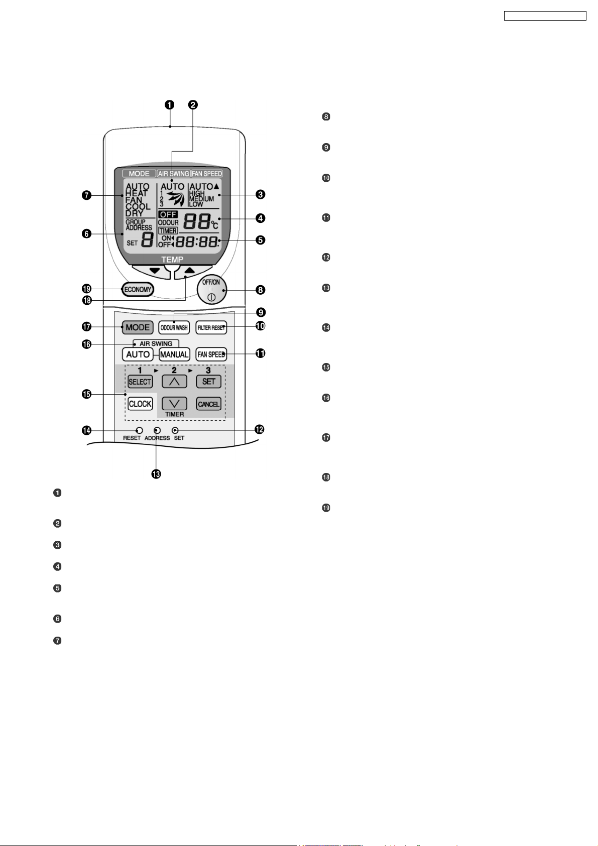
8.2. Wireless Remote Control (Optional part)
Name and function of each part
OFF/ON button
Used to start and stop the operation.
ODOUR WASH button
FILTER RESET button
Press to cancel the “FILTER” indicator light on the control
panel.
FAN SPEED button
Used to select the fan speed of high (HI), medium (MED), low
(LO) or auto (AUTO).
SET button*
Local setting function.
ADDRESS SET button*
Used to change the address setting when using more than one
indoor unit.
CS-F50DB4E5 CU-L50DBE8
Transmitter
Transmits the remote control signal.
Airflow direction setting display
Fan speed display
Temperature setting display (16°C - 31°C)
Time/time setting display
Shows the timer operation setting time or the current time.
RESET button
Pressing this button will clear all the settings from memory.
You will then need to make the settings again.
TIMER/CLOCK SET buttons
Used to set the timer operation and the current time.
AIR SWING (AUTO/MANUAL) buttons
Used to determine the air swing condition, either auto or
manual.
MODE button
Used to select the operation of AUTO, HEAT, FAN, COOL or
DRY.
TEMP (UP/DOWN) buttons
Used to select the desired temperature.
ECONOMY operation button
Address number display
Operation selection display
NOTES
•
•
Ensure that the correct button is pressed as simultaneous pressing of the multiple buttons will not make the setting correct.
• •
•
•
The illustration above is for explanatory purpose only. The appearance will be different during actual operation.
• •
•
•
If using the wireless remote control in conjunction with the wired remote control, the settings made from the wireless remote
• •
control will appear on the wired remote control display (except when making timer settings).
•
•
Buttons marked with * are not needed for normal operation. If one of these buttons is pressed by mistake, press the same
• •
button once more to cancel the operation.
•
•
When the power resumed after power failure, the unit will restart automatically with all previous settings preserved by the
• •
memory function. (Auto restart function)
21
Page 22
CS-F50DB4E5 CU-L50DBE8
9 Operation Control
Description of basic control functions
9.1. Operation Mode
1. Thermostat control
2. Depend on differences between room temperature and setting temperature, Compressor running frequency will be decided and
start operation.
Temperature differences become same as below table, then thermostat is off.
Temperature Differences
Unit: °C
Indoor type Cassette Ceiling Duct D2 Duct D3
Cool mode -1.5 -1.5 -2.0 -2.0
Dry mode -2.5 -2.5 -3.0 -3.0
Heat mode 3.5 2.5 2.5 2.5
3. Select indoor temperature thermostat
When connected to wired remote controller, either indoor unit thermostat or remote controller thermostat is available, using
remote control setting.
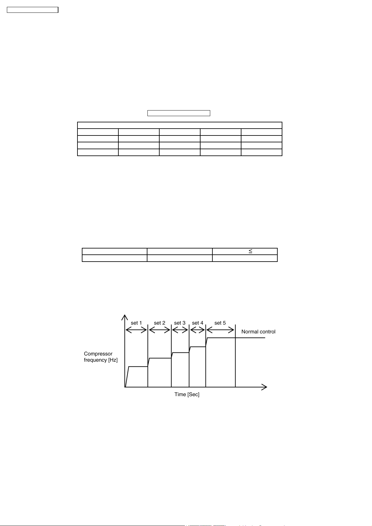
9.2. Compressor Start Control
•
•
When the compressor start, compressor frequency will be fixed at lower level for certain time, to follow the below table, due to
• •
avoid the compressor oil discharge.
•
•
Judging from compressor discharge temperature, decide the start conditio n to select either cool start control, or warm start
• •
control.
Discharge temp. [°C] >15°C 15°C
Start control Cool start Warm start
Warm start : set 1→*set 5→normal control
Cool start : set 1→set 2→set 3→set 4→*set 5→normal control
•
•
Note
• •
−
−
Frequency at *set 5 = frequency calculated by normal control
− −
−
−
In case of frequency at set n excess the frequency at set 5 in cool condition, skip from set n to set 4 and transfer to set 5.
− −
9.3. Cooling Operation
9.3.1. Cool indoor fan control
•
•
Fan speed manual
• •
Common control for unit using DC motor / unit using AC motor.
Operation start at hi speed, or medium speed, or low speed set by remote control.
•
•
Fan speed auto
• •
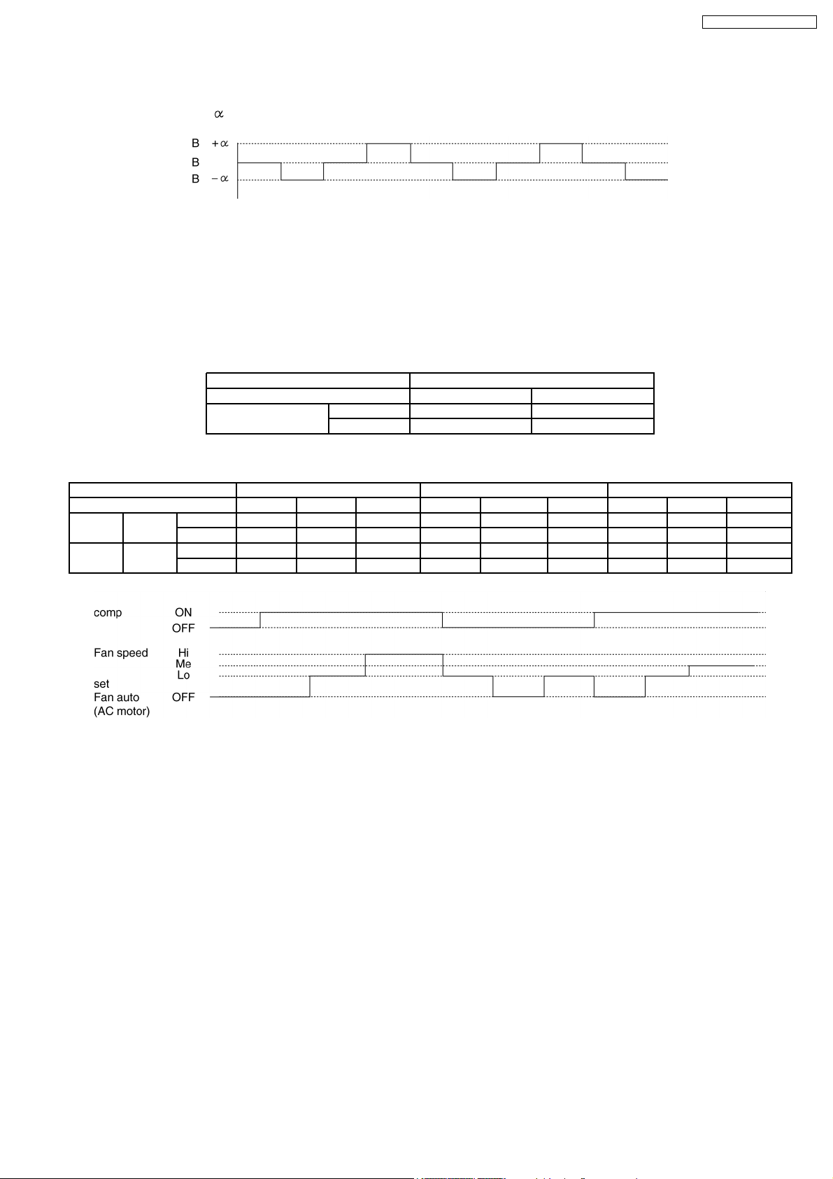
When operation start, or shifting to thermostat ON condition from thermostat OFF condition, odour cut operation (refer odour
cut operation page for detail), after thermostat ON condition, indoor fan operate as below control.
22
Page 23
CS-F50DB4E5 CU-L50DBE8
−
−
Unit using DC motor
− −
As follow the below figure, fan speed changing operation (program air).
(rpm center B and
−
−
Unit using AC motor
− −
is differen t if capacity rank is different)
When 1st thermostat on condition from operation start, fan speed is hi (same as manual fan speed), after 2nd thermostat
on condition, fan speed change to medium speed (same as manual medium fan speed).
9.3.2. Odour cut control
•
•
When cool or dry mode operation start, select odour cut mode or fan auto mode, by remote control, operation start at odour
• •
wash mode when compressor start or shift to thermostat on from thermostat off.
•
•
Odour cut operation is under below conditio n.
• •
Operation mode Cool or dry mode
Odour wash setting Setting No setting
Fan setting Auto Odour cut Odour cut
Manual Odour cut -
•
•
Odour cut operation is to remove the odour generated at indoor heat exchanger to use the drain water come out from indoor
• •
heat exchanger.
Thermo & comp ON/OFF Thermostat ON & comp ON Thermostat ON Thermostat ON & comp ON
Time 40 [Sec] 50 [Sec] - 20 [Sec] 120 [Sec] 20 [Sec] 40 [Sec] 50 [Sec] -
Cool Auto DC motor OFF SSLo Program air SSLo OFF SSLo OFF SSLo Program air
AC motor OFF Lo Hi Lo OFF Lo OFF Lo Me
Dry Auto DC motor OFF SSLo SLo SSLo OFF SSLo OFF SSLo SLo
AC motor OFF Lo Lo Lo OFF Lo OFF Lo Lo
9.3.3. Cool powerful operation
•
•
When cool or dry mode operation start, temperature differences between room temperature and setting temperature is more
• •
than 5 K, setting temperature shift to 2 K down.
•
•
(But when temperature after shifting is less than 16°C, setting temperature is 16°C = no change)
• •
•
•
Micro computer judge that required indoor load is bigger than calculation base from temperature differences between room
• •
temperature and setting temperature, then increase the compressor frequency compared to normal to cool down indoor side
immediately.
•
•
Those kind of operation complete after 30 minutes when cool mode operation start.
• •
23
Page 24
CS-F50DB4E5 CU-L50DBE8
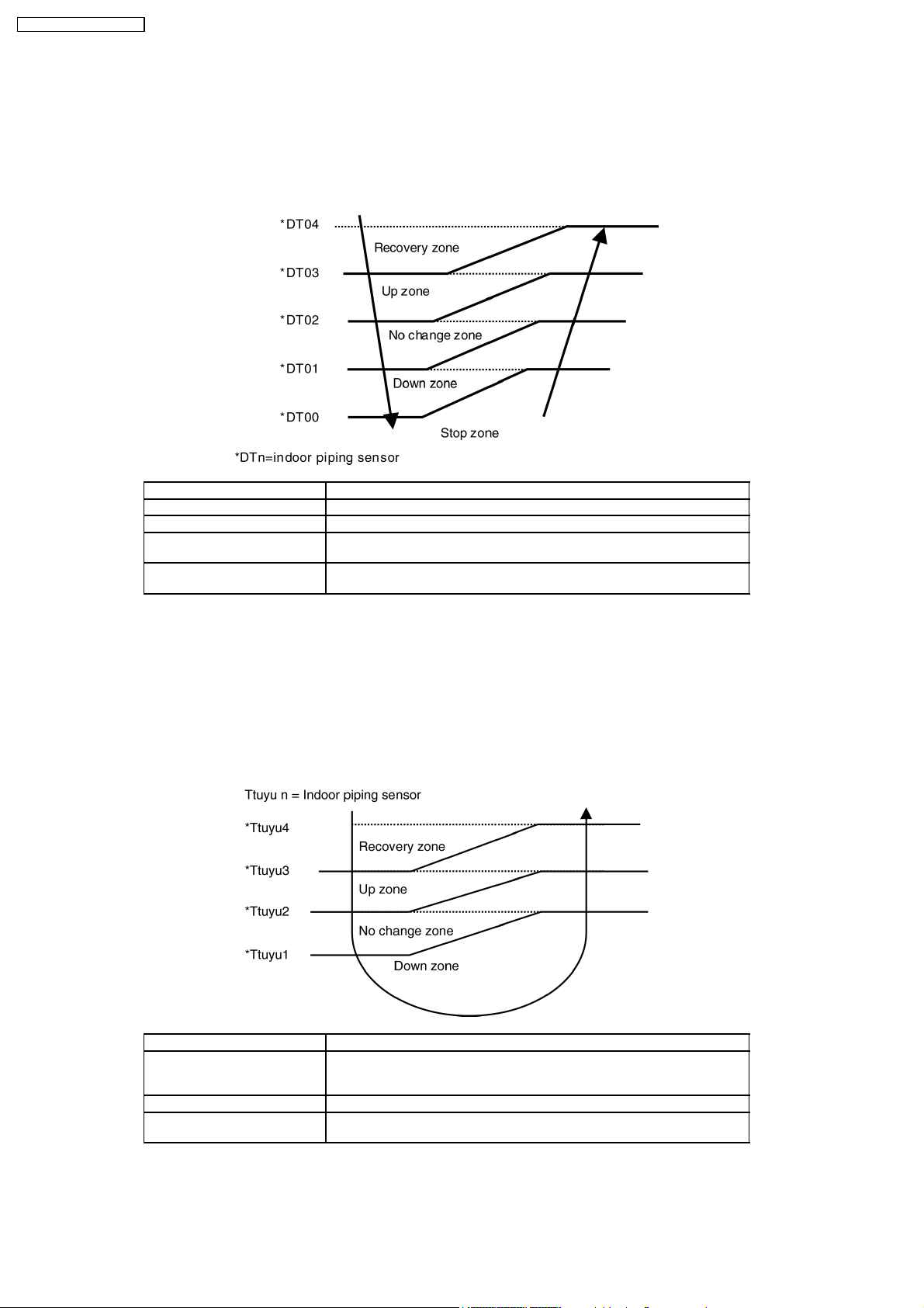
9.3.4. Freezing prevention control
•
•
During cool or dry mode operation, if indoor evaporator temperature is going down, freezing prevention control is operated.
• •
•
•
Detail of Freezing prevention control is as follows;
• •
Indoor evaporator temperature area is divided into 5 zones, which consist of stop zone, down zone, no change zone, up zone,
and recovery zone. When indoor evaporator temperature is going into each zone, compressor frequency change by followin g
the below table.
Recovery zone Release freezing prevention operation
Up zone Fan motor speed step up
No change zone Operation no change
Down zone Reduce the compressor frequency
Stop zone If continue for 6 min, compressor stop
(check for 3 min, max 3 times)
(for 3 min after stop, compressor can be started due to restart delay control)
9.3.5. Dew form prevention control
•
•
During cool or dry operation, if outdoor temperature is less than 30°C, and indoor fan speed is low or auto setting, indoor heat
• •
exchanger temperature become lower, dew form prevention control start to prevention dew form at indoor discharge grill.
•
•
Indoor evaporator temperature area is divided into 4 zones, which consist of, down zone, no change zone, up zone, and
• •
recovery zone.
•
•
When indoor evaporator temperature is going into each zone, change compressor frequency and louver angle by following the
• •
below table.
Recovery zone Release dew form prevention operation
Up zone Fix the indoor louver angle
No change zone Continue check the indoor heat excahnger temperature
Down zone Reduce the compressor frequency
Cassette type : fix the manual 3rd position
Ceiling type : fix the manual 2nd position
(check for 3 min, max 3 times)
24
Page 25
CS-F50DB4E5 CU-L50DBE8
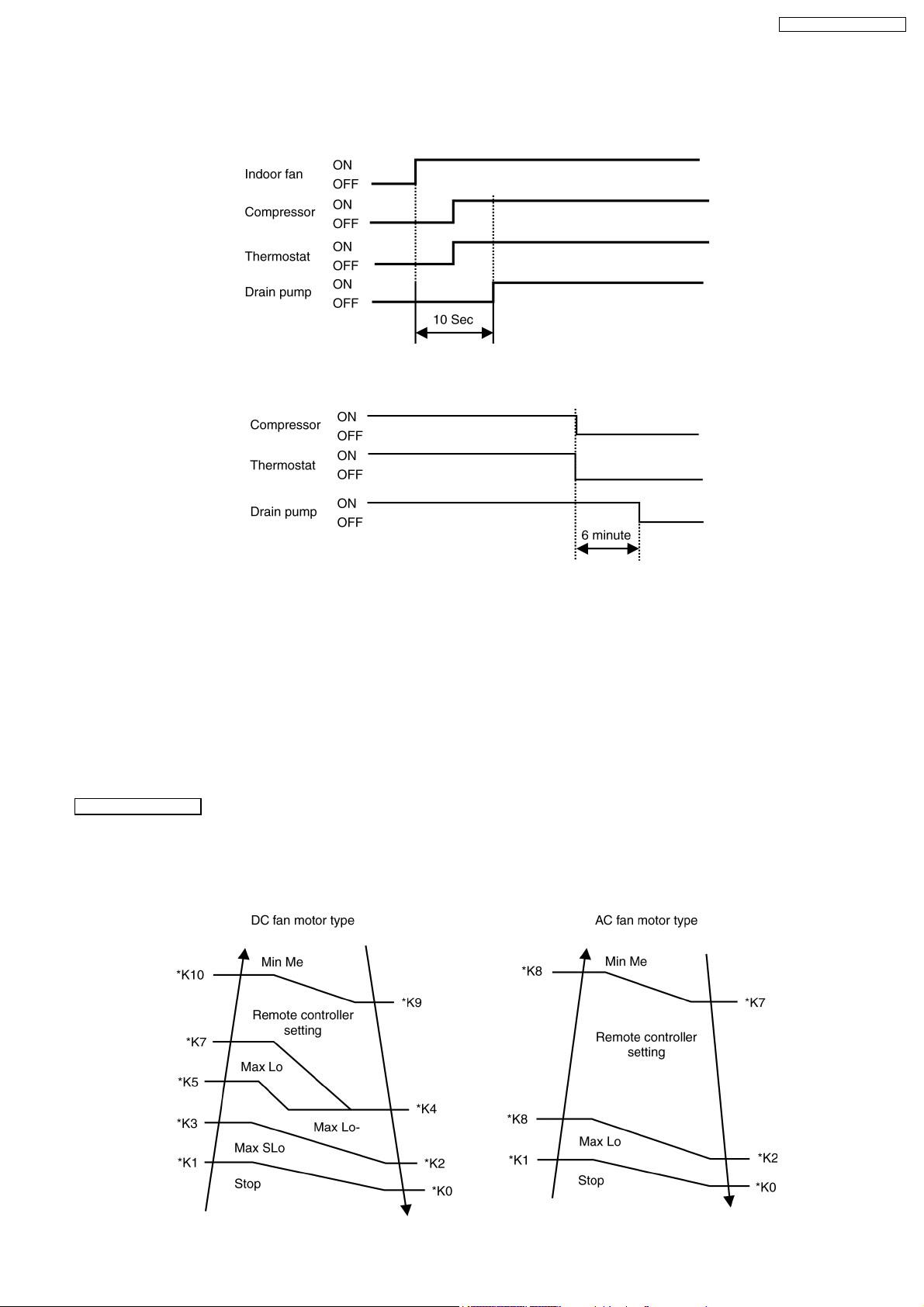
9.3.6. Drain pump control
•
•
During cooling, dry, or defrost operation, drain pump operate by followin g the below table.
• •
•
•
When compressor start, drain pump operation start after 10 second of indoor fan starting.
• •
•
•
When operation stop or thermostat is off, drain pump continue operating for 6 minute to prevent the drain water from coming
• •
back.
9.3.7. Cooling low temperature protection control
•
•
During cooling, or dry operation, if outdoor temperature is less than -15°C.
• •
−
−
And thermostat on condition continue for 15 min, compressor stop.
− −
−
−
After 3 min waiting (restart delay), if thermostat is on, compressor restart.
− −
9.4. Heating Mode Operation
9.4.1. Heating indoor fan control
Fan speed manual
•
•
Fan speed [Hi] [Me] [Lo] set by remote controller.
• •
•
•
However, when operation start, or during operation, fan speed control is limited to due to prevent a cold draft, for example, when
• •
heating operation start.
•
•
(K10 = Indoor heat exchanger temperature, depend on indoor type)
• •
25
Page 26
CS-F50DB4E5 CU-L50DBE8
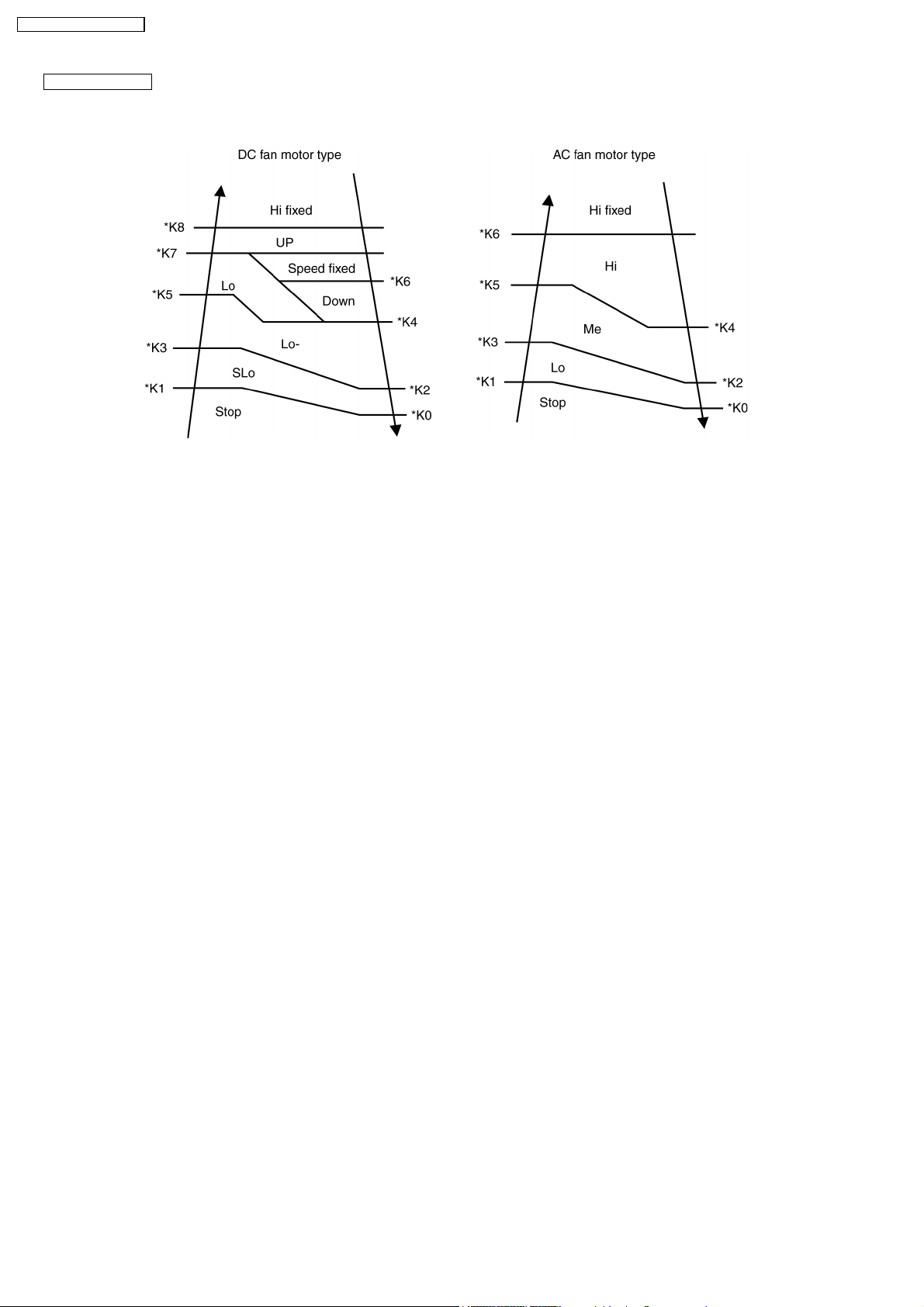
Fan speed auto
•
•
When operation start, or during operation, fan speed control by detecting indoor heat exchanger as follows:
• •
•
•
(K10 = Indoor heat exchanger temperature, depend on indoor type)
• •
9.4.2. Hot start control
•
•
When heating operation start, hot start control carry out.
• •
•
•
During hot start operation, [PREHEAT] displayed at the wired remote controller.
• •
•
•
For wireless remote controller, [POWER LED] is blinking at the receiver of indoor unit. Indoor fan stop and louver angle fixed
• •
to upper side in spite of any setting of remote controller. When indoor heat exchanger temperature increase, or 4 minute past
after operation start, hot start control finish and shift to normal fan control.
9.4.3. Heating indoor fan control at thermostat off heating mode operation
•
•
During heating operation, if thermostat is off, indoor fan fixed low speed, Louver angle fixed upper side, even if remote control
• •
display shows any angle.
(cassette and ceiling model only)
9.4.4. Heating powerful operation
•
•
When heating mode operation start, temperature differen ces between setting temperature and room temperature is more than
• •
5 K, setting temperature increase 2 K and operation start.
(however, setting temperature after shifting is more than 31°C, setting temperature fixed 31°C.)
•
•
Due to this control, micro computer judge indoor heat loss is big and increase compressor frequency compare to normal
• •
condition, then heat up indoor room quickly.
•
•
This control will be finished after 60 min or thermostat is off.
• •
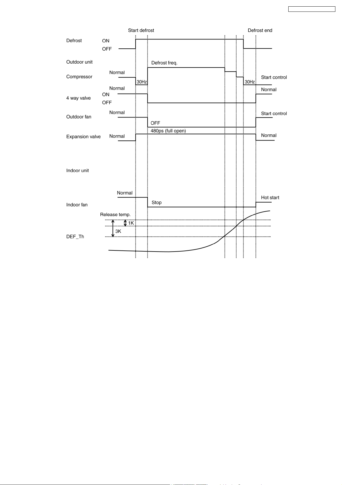
9.4.5. Defrost control
•
•
During heating operation at outdoor low temperature condition, defrost operation start timely to melt the ice formed on outdoor
• •
heat exchanger.
•
•
When heating operation accumulated time is time up, and both outdoor temperature and outdoor unit heat exchanger
• •
temperature is less than setting temperature for 5 minute. When defrost temperature is more than setting temperature, defrost
operation finish.
•
•
During defrost operation, in spite of any change of remote controller, indoor fan stop and louver angle fixed at upper side.
• •
(for louver control : cassette and ceiling model only)
•
•
During defrost operation, [DEFROST] is display ed at wired remote controller (when using wireless controller, POWER LED is
• •
blinking in receiver of indoor unit), hot start operate after defrost operation finish.
26
Page 27
CS-F50DB4E5 CU-L50DBE8
9.4.6. Heating high temperature protection
•
•
During heating operation, when outdoor temperature is more than 35°C for 15 minute, compressor stop to protect compressor.
• •
•
•
After 3 minute (re-start delat control) waiting, if thermostat on condition, outdoor unit re-start.
• •
27
Page 28
CS-F50DB4E5 CU-L50DBE8
9.5. Louver Control
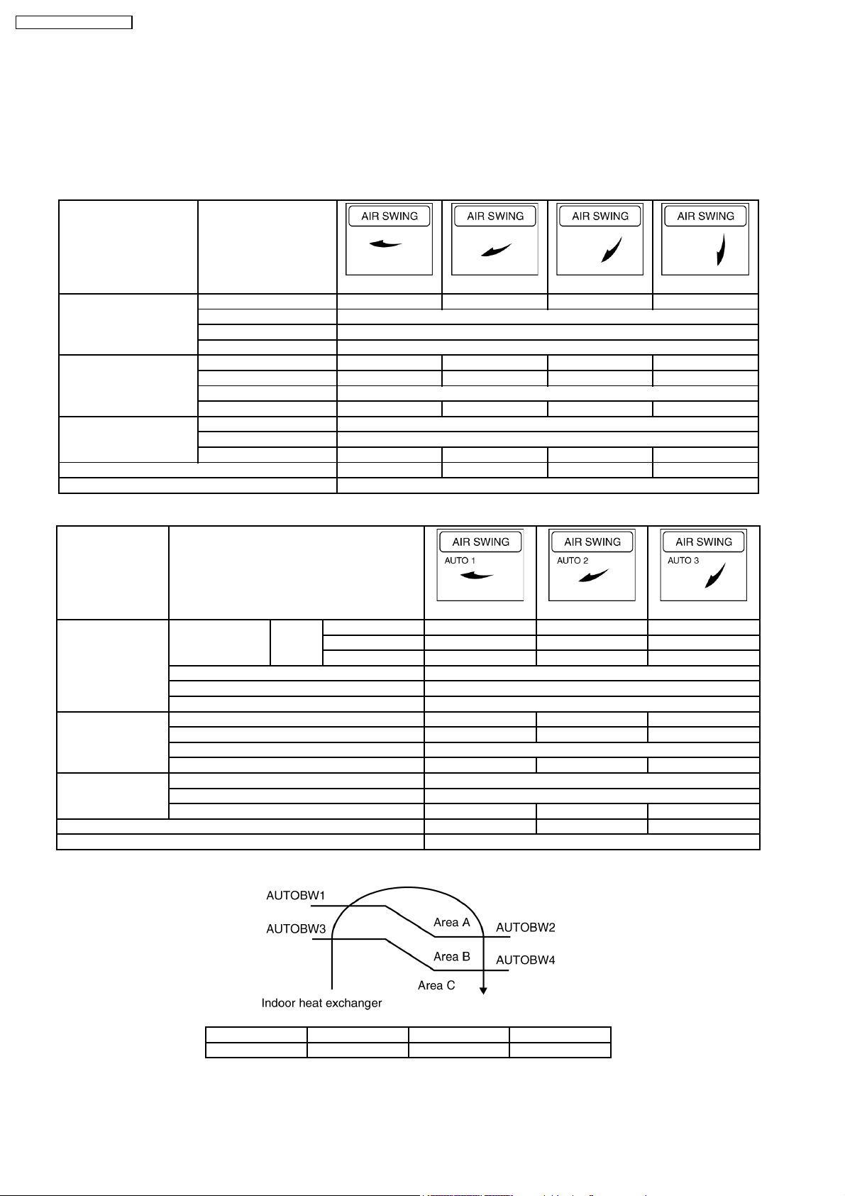
9.5.1. Louver control for cassette type
•
•
When power is on, at the same time, louver start initializing toward to close Direction.
• •
•
•
During operation, stopping, thermostat off condition, louver angle set manual or auto depend on remote controller setting.
• •
−
−
Louver manual setting
− −
Operation mode Display manual
Set 1 Set 2 Set 3 Set 4
Normal 20° 35° 50° 70°
Heating Defrost 10°
Hot start 10°
Thermostat off 20°
Fan 20° 35° 50° 70°
Cooling Normal 20° 35° 50° 70°
(fan) Dew control 50°
Thermostat off 20° 35° 50° 70°
Normal 30°
Dry Dew control 50°
Thermostat off 20° 35° 50° 70°
Operation mode judge 20° 35° 50° 70°
Stop mode 0°
−
−
Louver auto setting
− −
Operation Display auto set
AUTO 1 AUTO 2 AUTO 3
A 70° 70° 70°
Normal Sensor B 20° - 70° 20° - 50° 40° - 70°
Heating C 20° 20° 20°
Defrost 10°
Hot start 10°
Thermostat off 20°
Fan 20° - 70° 20° - 50° 40° - 70°
Cooling Normal 20° - 70° 20° - 50° 40° - 70°
(Fan) Dew control 50°
Thermostat off 20° - 70° 20° - 50° 40° - 70°
Normal 30°
Dry Dew control 50°
Thermostat off 20° - 70° 20° - 50° 40° - 70°
Operation mode judge 20° 20° 20°
Stop mode 0°
•
•
Temperature range for louver control during heating operation is as follows; decide by indoor heat exchanger temperature.
• •
AUTOBW1 AUTOBW2 AUTOBW3 AUTOBW4
60°C 57°C 30°C 25°C
28
Page 29
CS-F50DB4E5 CU-L50DBE8
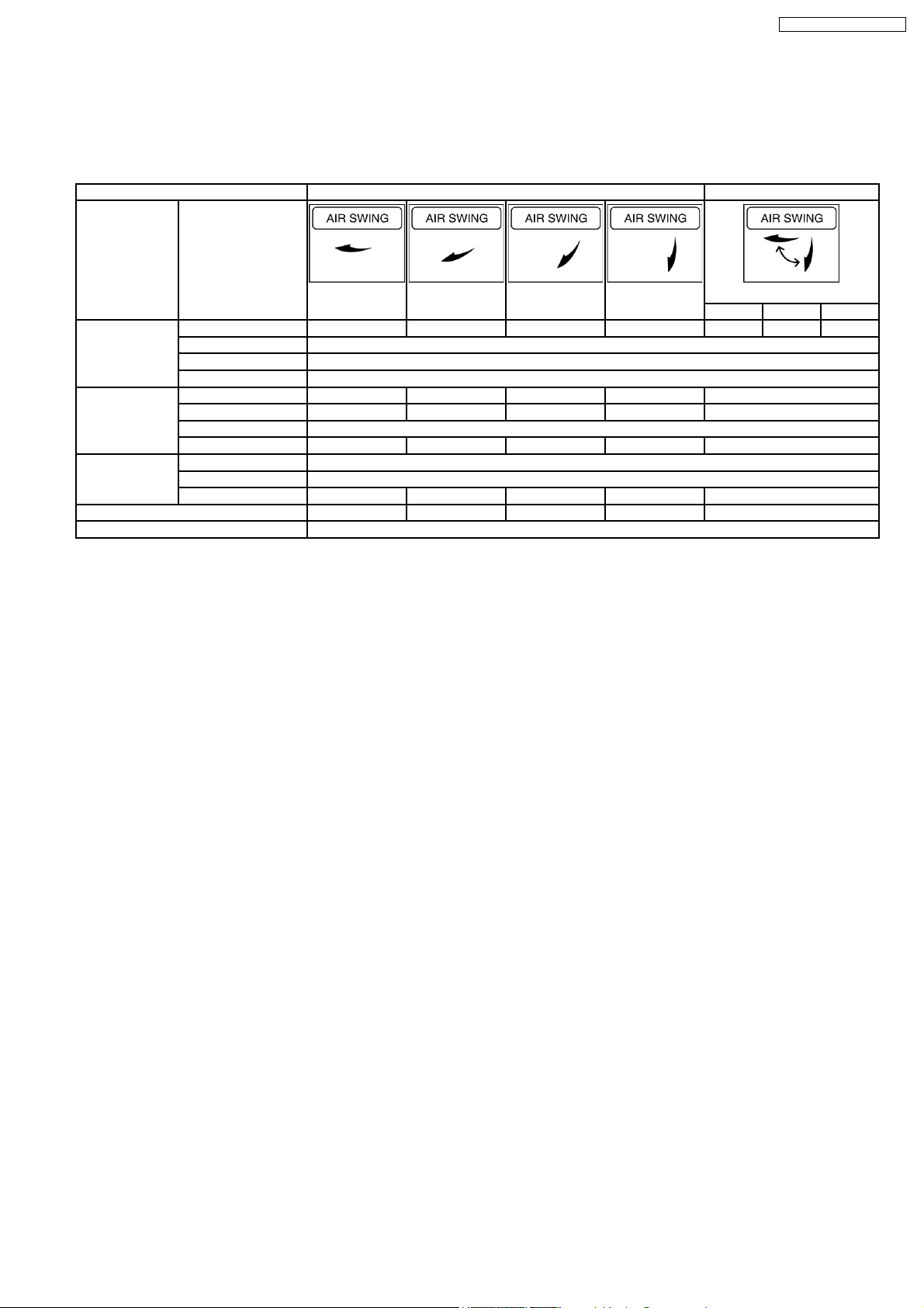
9.5.2. Ceiling type louver control
•
•
When power is on, at the same time, louver initialize 2 times.
• •
•
•
During operation, stopping, thermostat is off condition, louver angle change as below table by manual setting or auto setting of
• •
remote controller.
Remote controller setting Manual Auto
Operation mode Display
Set 1 Set 2 Set 3 Set 4 Piping temp (heating)
A B C
Normal 20° 35° 50° 70° 70° 20° - 70° Set 1
Heating Defrost 20°
Hot start 20°
Thermostat off 20°
Fan 20° 35° 50° 70° 20° - 70°
Cooling Normal 20° 35° 50° 70° 20° - 70°
(fan) Dew control 35°
Thermostat off 20° 35° 50° 70° 20° - 70°
Normal 35°
Dry Dew control 35°
Thermostat off 20° 35° 50° 70° 20° - 70°
Operation mode judge 20° 35° 50° 70° 20°
Stop mode 70°
29
Page 30
CS-F50DB4E5 CU-L50DBE8
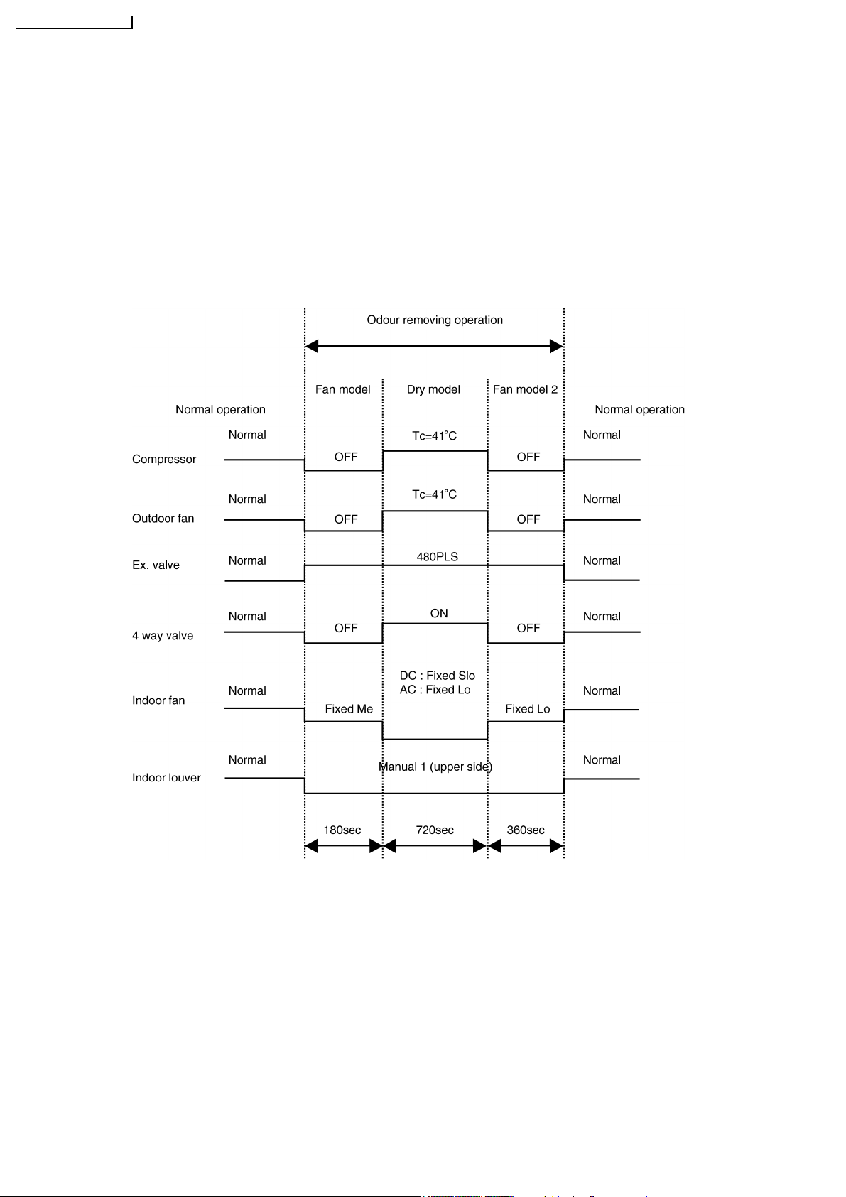
9.6. Odour Removing Operation
•
•
During stop condition, or cooling operation, when pushing the [ODOUR] button for 5 second, operation change to the odour
• •
removing operation.
•
•
Operation detail is as follows;
• •
Fan mode operation for 180 second, then refrigerant cycle change to heating mode for 720 second, to heat up (dry) the indoor
unit. Compressor frequency and indoor fan controlled to maintain the indoor heat exchanger temperature 41°C.
•
•
Indoor fan revolution is fixed (for DC motor type, fan speed is Slo, for AC motor type, fan speed is Lo), and indoor louver angle
• •
is fixed manual set no.1.
•
•
After that, fan mode operation continue for 360 second, then odour removing operation finish.
• •
•
•
During odour removing operation, [ODOUR] sign is blinking at LCD display panel of wired remote controller ([ODOUR WASH]
• •
sign is not displayed for wireless remote controller), when pushing the operation button, or [ODOUR] button, odour removing
operation finish and set the odour cut operation.
30
Page 31

CS-F50DB4E5 CU-L50DBE8
9.7. Energy Save Operation
•
•
During cooling operation, or heating operation, when pushing the [ECONOMY] button in the wired remote controller, energy
• •
save operation start and [ECO] sign is displayed at LCD display panel of wired remote controller ([ECONOMY] sign is displayed
at LCD display panel of wireless remote controller).
•
•
When energy save operation start and temperature differences is +1K (=indoor suction temperature - setting temperature) for
• •
cooling operation, or -1K for heating operation for 30 minute, thermostat OFF point shift to 0.5K.
(This means thermostat OFF point shift up +0.5K for cooling, thermostat OFF point shift down -0.5K for heating)
From this control, it is judged that indoor side heat loss is small, then reduce compressor frequency. This means energy save
operation.
•
•
Those kind of operation continue maximum 4 times. If temperature is out of range (thermostat off +1K for cooling, thermostat
• •
off -1K for heating), operation release from energy save control. But energy save control cannot be released by pushing
ON/OFF button of remote controller, but still effective. When pushing [ECONOMY] button once again, energy save control
released.
9.8. Outdoor Fan Remaining Heat Removal Control
•
•
When compressor stop, outdoor fan operate for 1 minute to remove the remaining heat.
• •
9.9. Crank Case Heater Control
•
•
Crank case heater power is on to prevent the refrigerant solving into compressor oil inside of the compressor shell at cold
• •
condition.
•
•
When below conditions are satisfied, crank case heater power on.
• •
−
−
Compressor stop
− −
−
−
Outdoor temperature
− −
−
−
Compressor discharge temperature
− −
15°C
15°C
9.10. Valve Error
•
•
When install the air conditioner unit and try to start forced operation (cooling mode) after completion the installation, in case of
• •
3 way valve close, valve error displayed at the wired remote controller to protect the compressor.
•
•
This error can be detected to satisfy below condition, when power is on at first time and within 7 minute from compressor start.
• •
(However, it is judged that power on is the first time until compressor start operating continuosly for 7 minute)
−
−
Indoor heat exchanger temperature when compressor start - 3K < current indoor heat exchanger temperature for 5 minute
− −
−
−
Indoor suction temperature - 3K < current heat exchanger temperature for 5 minute.
− −
31
Page 32

CS-F50DB4E5 CU-L50DBE8
9.11. Pump Down Operation
•
•
When pushing the [PUMP DOWN] button on the outdoor PCB for 1 second, pump down operation start. Detail of pump down
• •
operation is shown at below table.
•
•
During pump down operation, push the [PUMP DOWN] button once again for 1 second, pump down operation stop.
• •
•
•
After 600[Sec] past, pump down operation stop.
• •
9.12. Indoor Air Volume Up Control (DC Fan Motor Type Only)
•
•
Indoor air volume up control set by local setting mode of wired or wireless remote controller.
• •
(item 01, 00: standard / 01: Air volume up mode)
(only for DC motor type)
•
•
Due to air volume up control, indoor fan revolution increase in case of Hi speed setting only.
• •
•
•
This control is memorized in the micro computer, it cannot be reset by power off.
• •
32
Page 33

CS-F50DB4E5 CU-L50DBE8
10 Installation Instruction
10.1. Pipe length
•
•
CORRECTION OF COOLING CAPACITY AND HEATING CAPACITIES
• •
1. Correction of cooling and heating capacities according to the connecting pipe length.
The Data of cooling capacities (marked on the name plate) are based on 5 meters connecting pipe and horizontal installation.
For other pipe length of other installation multiply by the following correction factor to determine the revised cooling capacity.
Equivalent Length = actual pipe length + number of elbow x ELE + number of oil trap x ELO
ELE : equivalent length of elbow
ELO : equivalent length of oil trap
2. For other pipe length of other installation multiply by the following correction factor to determine the revised cooling capacity.
Outer diameter of gas side pipe
mm (inch)
12.7 (1/2) 0.20
15.88 (5/8) 0.25
19.05 (3/4) 0.35
6.35 (1/4) 0.18
33
Page 34

CS-F50DB4E5 CU-L50DBE8
10.2. Refrigerant additional charge
Piping installation by standard piping
1.
•
•
At the time of shipment from the factory, this unit is charged with enough refrigerant for an equivalent pipe length of 30 m.
• •
(Refer the following table)
But when the piping length exceeds 30m, additional charge is required according to the followin g table.
Example:
CU-L50DBE8
In case of 50m long pipe (one way), the amount of refrigerant to be replenished is: (50 - 30) x 50 = 1,000g
Model Name Standard piping specification
Liquid piping
CU-L34DBE5 9.53 15.88 30 50
CU-L43DBE5 9.53 15.88 30 50
CU-L50DBE8 9.53 15.88 30 50
Attention
•
•
Do not decrease the size of the gas piping. (It causes the breakdown of the compressor)
• •
(dia.mm)
Gas piping
(dia.mm)
Gas charge-
less length
(m)
Additional
gas volume
(g/m)
10.3. Position of the centre gravity
MODEL NAME OUTSIDE DIMENSIONS NET WEIGHT CENTRE OF GRAVITY
WIDTH (mm) DEPTH (mm) HEIGHT (mm) kg X (mm) Y (mm) Z (mm)
CU-L34DBE5 900 320 1340 110 720 160 460
CU-L43DBE5 900 320 1340 110 720 160 460
CU-L50DBE8 900 320 1340 110 720 160 460
34
Page 35

CS-F50DB4E5 CU-L50DBE8
10.4. Indoor unit installation
FOUR WAY CASSETTE TYPE AIR CONDITIONERS INSTALLAT ION INSTRUCTIONS
Precautions in terms of safety
Carry out installation work with reliability after through reading of this “Precautions in terms of safety”.
•
•
Precautions shown here are differentiated between
• •
leading to significant result such as fatality or serious injury if wrong installation would have been carried out are listed compiling
them especially into the column of
Warnings .
Warnings and Cautions . Those that have much chances for
However, even in the case of items which are listed in the column of
Cautions , such items also have a chance for leading
to significant result depending on the situations.
In either case, important descriptions regarding the safety are listed, then observe them without fail.
•
•
As to indications with illustration
• •
This mark means “Caution” or “Warning”. This mark means “Earth”.
•
•
After installation work has been completed, do not only make sure that the unit is free from any abnormal condition through the
• •
execution of trial run but also explain how to use and how to perform maintenance of this unit to the customer according to the
instruction manual.
In addition, request the customer to keep this manual for installation work together with instruction manual.
Warnings
The appliance must be installed by technician, who takes into
account the requirements given by ISO5149 or eventual
equivalent requirements.
As to installation, request the distributor or vendor to perform it.
Imperfection in installation caused by that having been carried
out by the customer himself may leads to water leakage, electric
shock, fire, etc.
Carry out the installation work with reliability according to this
manual for installation work.
Imperfection in installation leads to water leakage, electric shock,
fire, etc.
Carry out the installation work with reliability on the place that
can bear the weight of this unit sufficiently. Insufficient strength
leads to injury due to falling of the unit.
Carry out predetermined installation work in preparation for
strong wind such as typhoon, earthquake. Imperfection in
installation work may lead to accidents arisen from overturn, etc.
The unit must be installed in accordance with applicable national
and local regulations. Any electrical work should only be carried
out by qualified technician and use exclusive circuits without fail.
Presence of insufficient capacity in power circuit or imperfection
in execution leads to electric shock, fire, etc.
Wiring shall be connected using specified cables and fix them
securely so that external force of the cables may not transfer to
the terminal connection section.
Imperfect connection and fixing leads to fire, etc.
If installing inside a small room, measures should be taken to
prevent refrigerant levels from building up to critical
concentrations in the event of a refrigerant leak occurring.
Please discuss with the place of purchase for advice on what
measures may be necessary to prevent critical concentrations
being exceeded. If the refrigerant leaks and reaches critical
concentration levels, there is the danger that death from
suffocation may result.
Securely attach the protective covers for the outdoor unit
connection cables and power cord so that they do not lift up
after installation. If the covers are not properly attached and
installed, the terminal connections may overheat, and fire or
electric shock may result.
Switch off all supplies before accessing any electrical part.
If refrigerant gas escapes during installation, ventilate the
affected area. If the refrigerant gas comes into contact with
sparks or naked flames, it will cause toxic gases to be
generated.
Once installation work is completed, check that there are no
refrigerant gas in the room that can come into contact with
sparks or flames from a fan heater, stove or kitchen range,
which will cause toxic gases to be generated.
When performing piping work do not mix air except for specified
refrigerant (R410A) in refrigeration cycle. it causes capacity
down, and risk of explosion and injury due to high tension inside
the refrigerant cycle.
35
Page 36

CS-F50DB4E5 CU-L50DBE8
Cautions
Carry out Earthing work.
Do not connect the Earth return to the gas pipe,
water line pipe, lightning rod and telephone lines.
Imperfection in Earth return may lead to electric
shock.
Do not install the unit at the place where the possibility of
inflammable gas leakage exists. If gas leakage should arise and
the gas builds up around the unit, such situation may lead to
ignition.
Mounting of the earth leakage circuit breaker is required.
Omission in mounting of the earth leakage circuit breaker may
lead to electric shock.
Drain piping should be made to ensure secure drainage
according to the manual for installation work and carry out the
thermal insulation to prevent the occurrence of condensation.
Imperfection in piping work lead to water leakage and may
cause the house and property, etc. to become wet
Position the indoor unit and outdoor unit, power cords and
indoor/outdoor unit connection cables in a way so that they are
at least 1 meter away from televisions and radios.
This is to avoid problem such as interference with picture and/or
sound. (However, note that depending on the electromagnetic
wave conditions, interference may still occur even if the
separation distance is more than 1 meter.)
10.4.1. Accessories packed in the indoor unit container
Name Q’ty Appearance Purpose Name Q’ty Appearance Purpose
Drain hose with
a clip
Heat insulator 2 For insulating refrigerant
1 For drain piping Flat washer for
M10
Screw M5 4 Set screw for paper model
pipe joint
8 For fixing the hanging
bolts
and panel fixing
Band 4 For fastening the heat
insulator
10.4.2. Selecting the location for indoor unit
Provide a check port on the piping side ceiling for repair and maintenance.
•
•
Install the indoor unit once the following conditions are satisfied and after receiving the customer approval.
• •
1. The indoor unit must be within a maintenance space.
2. The indoor unit must be free from any obstacles in path of the air inlet and outlet, and must allow spreading of air throughout
the room.
* If the height from the floor to ceiling exceeds three meters, air flow distribution deteriorates and the effect is decreased.
3. The installation position must be able to support a load four times the indoor unit weight.
4. The indoor unit must be away from heat and steam sources, but avoid installing it near an entrance.
5. The indoor unit must allow easy draining.
6. The indoor unit must allow easy connection to the outdoor unit.
7. Place the indoor unit according to the height from the ceiling shown in the illustration below.
8. The indoor unit must be from at least 3m away from any noise-generating equipment. The electrical wiring must be shielded
with a steel conduit.
9. If the power supply is subject to noise generation, add a suppressor.
10. Do not install the indoor unit at a laundry. Electric shocks may result.
Warnings
NOTE
•
•
Thoroughly study the following installation locations.
• •
36
Page 37

CS-F50DB4E5 CU-L50DBE8
1. In such places as restaurants and kitchens, considerable amount of oil steam and flour adhere to the turbo fan, the fin of the
heat exchanger and the drain pump, resulting in heat exchange reduction, spraying, dispersing of water drops, drain pump
malfunction, etc.
In these cases, take the following actions:
•
•
Make sure the ventilation fan for smoke-collection hood on a cooking table has sufficient capacity so that it draws oily steam
• •
which should not flow into the suction of the air conditioner.
•
•
Make enough distance from cooking room to install the air conditioner in such place where it may not suck in oily steam.
• •
2. Avoid installing the air conditioner in such circumstances where cutting oil mist or iron powder exist especially in factories, etc.
3. Avoid places where inflammable gas is generated, flows-in, contaminated, or leak.
4. Avoid places where sulphurous acid gas or corrosive gas can be generated.
5. Avoid places near high frequency generators.
Model Name Height in the ceiling
CS-F24DB4** CS-F28DB4** 246 mm or more
CS-F34DB4** CS-F43DB4** 288 mm or more
CS-F50DB4**
10.4.3. Installation of indoor unit
This air conditioner uses a drain up motor.
Horizontally install the unit using a level gauge.
CEILING OPENING DIMENSIONS AND HANGING BOLT LOCATION
The paper model for installation expand or shrink according to temperature and humidity.
Check on dimensions before using it.
Caution During the installation, care must be taken not to damage the electric wires.
•
•
The dimensions of the paper model for installation are the same as those of the ceiling opening dimensions.
• •
•
•
Be sure to discuss the ceiling drilling work with the workers concerned.
• •
37
Page 38

CS-F50DB4E5 CU-L50DBE8
Warning Tighten the nuts and bolt to prevent unit from falling.
POSITIONS OF AIR CONDITIONER BODY AND CEILING SURFACE
HANGING POSITION OF THE AIR CONDITIONER BODY
10.4.4. Refrigerant piping
Refrigerant is charged to the outdoor unit. For details, see the manual for installation work of outdoor unit.(Additional charging,
etc.)
1. Brazing for piping.
a. Execute brazing before tightening the flare nut.
b. Brazing must be execute d while blowing nitrogen gas.
(This prevents generation of oxidized scale in copper pipe.)
2. When there is a lot of brazing for long piping, install a strainer at the midway of the piping.
(The strainer is locally supplied.)
3. Use clean copper pipe with inner wall surface free from mist and dust. Blow nitrogen gas or air to blow off dust in the pipe before
connection.
4. Form the piping according to its routing. Avoid bending and bending back the same piping point more than three times.
(This will result in hardening of the pipe).
5. After deforming the pipe, align centers of the union fitting of the indoor unit and the piping and tighten them firmly with wrenches.
6. Connect pipe to the service valve or ball valve which is located below the outdoor unit.
7. After completed the piping connection, be sure to check if there is gas leakage in indoor and outdoor connection.
38
Page 39

•
•
Confirm the red mark of the union (thin side) is always at lower direction after connecting piping.
• •
Vacuum drying
After completing the piping connection, execute vacuum drying for the connecting piping and the indoor unit.
The vacuum drying must be carried out by using the service ports of both the liquid and gas side valves.
CAUTION Use two wrenches and tighten with regular torque.
Flare nut fastening torque N.m (kgf.cm)
ø6.35 mm 18 (180) ø12.7 mm 55 (560) ø19.05 mm 100 (1020)
ø9.52 mm 42 (430) ø15.88 mm 65 (660)
Liquid side piping Gas side piping
ø9.52 mm ø15.88 mm
CS-F50DB4E5 CU-L50DBE8
10.4.5. Indoor unit drain piping
•
•
Drain piping must have down-slope (1/50 to 1/100): be sure not to provide up-and-down slope to prevent reversal flow.
• •
•
•
During drain piping connection, be careful not to exert extra force on the drain port at the indoor unit.
• •
•
•
The outside diameter of the drain connection at the indoor unit is 32 mm.
• •
Piping material: Polyvinyl chloride pipe VP-25 and pipe fittings
•
•
Be sure to perform heat insulation on the drain piping.
• •
Heat insulation material: Polyethylene foam with thickness more than 8mm (local supply).
Drain Test
The air conditioner uses a drain up motor to drain water. Use the following procedure to test the drain up motor operation.
•
•
Connect the main drain pipe to exterior and leave it provisionally until the test comes to an end.
• •
•
•
Feed water to the flexible drain hose and check the piping for leakage.
• •
•
•
Be sure to check the drain up motor for normal operating and noise when electric wiring is complete.
• •
39
Page 40

CS-F50DB4E5 CU-L50DBE8
•
•
When the test is completed, connect the flexible drain hose to the drain port.
• •
10.4.6. Heat insulation
Caution Be sure to perform heat insulation on the drain, liquid and gas piping. Imperfection in heat insulation work leads to water
leakage.
1. Use the heat insulation material for the refrigerant piping which has an excellent heat-resistance (over 120°C).
2. Precautions in high humidity circumstance.
This air conditioner has been tested according to the “JIS Standard Conditions with Mist” and have been confirmed that there
are no faults. However, if it is operated for a long time in high humid atmosphere (dew point temperature: more than 23°C),
water drops are liable to fall. In this case, add heat insulation material according to the following procedure:
•
•
Heat insulation material to be prepared... Adiabatic glass wool with thickness 10 to 20 mm.
• •
•
•
Stick glass wool on all air conditioners that are located in ceiling atmosphere.
• •
•
•
In addition to the normal heat insulation (thickness: more than 8 mm) for refrigerant piping (gas piping: thick piping) and
• •
drain piping, add a further of 10 mm to 30 mm thickness material.
Wall seal
•
•
When the outdoor unit is installed on a higher position than the indoor unit, install the trap so as not to instill rain water into
• •
the wall by transmitted in piping.
•
•
Stuff the space among piping, the electric wire, and the drain hose with “Putty” and seal the penetration wall hole.
• •
Make sure that rain water do not instill into the wall.
40
Page 41

CS-F50DB4E5 CU-L50DBE8
10.4.7. Electrical wiring
As to the main power source and cable size of outdoor unit, read the installation manual attached to the outdoor unit.
Warning
Caution Be sure to install a current leakage breaker or circuit breaker to the main power supply, otherwise electric shocks may result.
The units must be installed in accordance with applicable national and local regulations.
The units installed by a professional installer must be supplied from a dedicated electrical circuit.
All electric work must be carried out by a qualified technician according to proper technical standards for electrical work and
according to installation manual for installation work.
If circuits with insufficient capacity are used, or if electrical work is not carried out properly, electric shocks or fire may result.
Caution
Warning
Be sure to connect the unit to secure earth connection. (with a earth resistance of 100Ωor less)
If the earthing work is not carried out properly, electric shock may result.
Wiring shall be connected securely using specified cables and fix them securely so that external force of the cables may not
transfer to the terminal connection section. Imperfect connection and fixing leads to fire, etc.
1. Select a power source that is capable of supplying the current required by the air conditioner.
2. Feed the power source to the unit via a distribution switch board designed for this purpose, the switch should disconnected all
poles with a contact seperation of at least 3 mm.
3. Always ground the air conditioner with a grounding wire and screw to meet the LOCAL REGULATIONS.
4. Be sure to connect the wires correctly to terminal board with connecting the crimp tyre ring terminal to the wires.
5. Be sure to turn off the main power before installing and connecting the remote controller.
Note
•
•
Use the standard power cord for Europe (such as HO5RN-F or HO7RN-F which conforms to CENELEC (HAR) rating
• •
If momentarily turning on the power supply for both the indoor and outdoor units, do not turn the power off after at least 1
minute has passed. (for the system’s automatic setting.)
Turning off the power supply on the way may cause an abnormal operation.
specifications) or use the cable based on IEC standard. (245IEC57, 245IEC66)
CONNECTING THE WIRES TO THE CONTROL BOX
•
•
Remove a one mounting screw, remove the control box cover, and then connect the wires by following the procedure given in
• •
the illustration.
Caution Make sure that screws of the terminal are securely tightened.
41
Page 42

CS-F50DB4E5 CU-L50DBE8
Earth lead wire shall be longer than other lead wires as shown in the figure for the electrical safety in case of the slipping out of the
cord from anchorage.
10.4.8. Settings
Do not operate the remote controller within 1 minute after turning on the power of the indoor unit.
When using group control with the standard type, at least 1 unit must be set at No.1 at the indoor unit.
Check the settings of the indoor unit in a case where there are no display at remote controller. If there is no problem to the settings,
either group control or standard type should be set at No.16 at the indoor unit before turning the power on again.
•
•
All sets in the group which uses the same remote controller thermistor settings can be controlled by the same remote controller
• •
thermistor.
•
•
Up to a maximum of 16 indoor units can be connected at the time of group control. (Do not connect heat pump unit with cooling
• •
only unit.)
•
•
Indoor unit No. will be set automatically at the time of group control. However, which indoor unit uses which number is unknown.
• •
Indoor unit No. is also possible to be set manually with DIP switches. Since manual address setting has priority to automatic
address setting. To perform automatic address settings after doing manual setting, turn off all DIP switches from No.1 to No.4,
and then stop the operation. Then press three switches such as [AIR SWING AUTO] . [MODE]. [A/C No.] at the same time. (Do
not use manual address setting and automatic address setting together.)
•
•
Centralized control is possible for master unit and slave unit at the time of group control.
• •
42
Page 43

10.4.9. Installation of decorative panel
The decorative panel has its installation direction.
Confirm the direction by displaying of the piping side.
Before installing the decorative panel, always remove the paper template.
CS-F50DB4E5 CU-L50DBE8
1. Remove the air inlet grill from the decorative panel.
2. Remove the corner cover in 4 corner places.
Pull hook of corner cover as direction
, at same time remove it by sliding out in direction .
3. Fix the hanger (2 pieces) of the decorative panel to the indoor unit.
There is direction information at decorative panel [PIPING SIDE] indication meaning the direction of piping side.
43
Page 44

CS-F50DB4E5 CU-L50DBE8
4. Adjust between decorative panel fixing hole and indoor unit screw hole.
5. Fix decorative panel with 4 screws with already fix at paper model for installation.
Caution Install certainly the decorative panel.
Cool air leakage causes sweating.→Water drops fall.
6. Adhere the cosmetic panel and ceiling wall together and corfirm no gap in between. Readjust indoor unit height, if there is a gap
between ceiling wall and decorative panel although it have been fixed by screw.
If there are no effect to the indoor unit level and drain piping etc., the adjustment of indoor unit height can be adjusted through
the corner hole. Tighten back firmly the fixing nut of indoor unit after adjustment has been made.
44
Page 45

7. Open the indoor control box cover. (2 pcs)
8. Insert firmly the connector of cosmetic louver to indoor pcb CN-STM1 and CN-STM2.
Be caution not to clamp the cord in between control board and control board cover.
CS-F50DB4E5 CU-L50DBE8
9. After complete, install back removed part follow opposite procedure.
Warning Be sure to hook the air inlet grill string, to prevent grill from falling and causing injury from it.
If fixing wireless remocon, follow the instruction manual that include inside wireless remocon accessory.
(Remote Control Address Setting)
(Refer to the Installation Manual which is provided with the remote controller for details.)
•
•
Two remote controllers (including the wireless remote controller) can be connected. However, remote control thermistor
• •
setting is not possible.
•
•
As for [master/slave] setting of remote controller, the automatic setting and manual setting are possible. Since manual
• •
setting is priority.
•
•
Two remote controllers, which both are wireless, cannot be connected.
• •
10.4.10. As for timer output
•
•
Connect the timer cord to connector (CN-TIMER) on print circuit board.
• •
10.4.11. Precautions in test run
•
•
The initial power supply must provide at least 90% of the rated voltage. Otherwise, the air conditioner may not operate.
• •
•
•
Test operation can be carried out using the remote control unit or at the outdoor unit. (If carrying out test operation at the
• •
outdoor unit, refer to “TEST OPERATION” in the outdoor unit installation manual.)
•
•
If using the remote control unit to carry out test operation, follow the procedure given below.
• •
45
Page 46

CS-F50DB4E5 CU-L50DBE8
NOTE 1 These units are equipped with connection error prevention circuits. If the units do not operate, it is possible that the
•
•
First, press the OFF/ON (
• •
•
•
Then press the TEST RUN button within 1 minute of pressing the OFF/ON (
• •
) button.
button.
•
•
Next, select the operation modes.
• •
•
•
The temperature of the indoor unit pipes will be shown on the temperature setting
• •
display. (At the start of the test operation, it may take up to 1 minute for air
conditioner number, switching time and other displays to appear.)
•
•
After operation modes have been selected, stop the compressor for a moment.
• •
•
•
Press the OFF/ON (
• •
) button of the TEST RUN button once more to cancel test
operation mode.
connection error prevention circuits have operated. In such cases, check that the Indoor/outdoor unit connection wire
(connected to terminals
Normal operation should then commence.
, and ) are connected correctly. If they are connected incorrectly, connect them correctly.
)
NOTE 2 Do not short the remote control unit wires to each other. (The protection circuit will be activated and the units will not operate.)
NOTE 3 When running the units in heating mode during test operation, be sure to run the units in cooling mode first before selecting
NOTE 4 Test operation should be carried out for a minimum of 5 minutes. (Test operation will be cancelled automatically after 30
NOTE 5 Test operation mode should always be cancelled once test operation itself has been completed.
Once the cause of the short is eliminated, normal operation will then be possible.
this mode. If heating mode is selected first, it may cause problems with operation of the compressor. (Heat pump model only.)
minutes.)
10.4.12. Check the following items when installation is complete
•
•
After completing work, be sure to measure and record trial run properties, and store measuring data, etc.
• •
•
•
Measuring items are room temperature, outside temperature, suction temperature, blow out temperature, wind velocity, wind
• •
volume, voltage, current, presence of abnormal vibration and noise, operating pressure, piping temperature, compressive
pressure, airtight pressure.
•
•
As to the structure and appearance, check the following items .
• •
Is circulation of air adequate?
Is draining smooth?
Is heat insulation complete (refrigerant and drain piping)?
Is there any leakage of refrigerant?
Is remote control switch operated?
Is there any faulty wiring?
M3...69-98 N.cm {7-10 kgf.cm}
M4...157-196 N.cm {16-20 kgf.cm}
M5...196-245 N.cm {20-25 kgf.cm}
Are the terminal screws loosened?
10.4.13. Hand over
•
•
Teach the customer the operation and maintenance procedures, using the operation manual (air filter cleaning, temperature
• •
control, etc.)
As to parts to be sold separately
•
•
With regards to installation of the parts sold separately, follow the installation manual which is provided with the parts sold
• •
separately
As for work specifications of the outdoor unit, read the OUTDOOR UNIT INSTALLATION MANUAL attached to the outdoor
unit.
46
Page 47

CS-F50DB4E5 CU-L50DBE8
10.5. Outdoor unit installation
AIR CONDITIONERS OUTDOOR UNIT INSTALLAT ION INSTRUCTIONS
Precautions in terms of safety
Carry out installation work with reliability after thorough reading of this “Precautions in terms of safety”.
•
•
Precautions shown here are differentiated between
• •
leading to significant result such as fatality or serious injury if wrong installation would have been carried out are listed compiling
them especially into the column of
Warnings .
Warnings and Cautions . Those that have much chances for
However, even in the case of items which are listed in the column of
Cautions , such items also have a chance for leading
to significant result depending on the situations.
In either case, important descriptions regarding the safety are listed, then observe them without fail.
•
•
As to indications with illustration
• •
This mark means “Caution” or “Warning”. This mark means “Earth”.
•
•
After installation work has been completed, do not only make sure that the unit is free from any abnormal condition through the
• •
execution of try run but also explain how to use and how to perform maintenance of this unit to the customer according to the
instruction manual.
In addition, request the customer to keep this manual for installation work together with instruction manual.
Warnings
The appliance must be installed by technician, who takes into
account the requirements given by ISO5149 or eventual
equivalent requirements.
As to installation, request the distributor or vendor to perform it.
Imperfection in installation caused by that having been carried
out by the customer himself may lead to water leakage, electric
shock, fire, etc.
Carry out the installation work with reliability according to this
manual for installation work.
Imperfection in installation leads to water leakage, electric
shock, fire, etc.
Carry out the installation work with reliability on the place that
can bear the weight of this unit sufficiently. Insufficient strength
leads to injury due to falling of the unit.
Carry out predetermined installation work in preparation for
strong wind such as typhoon, earthquake.
Imperfection in installation work may lead to accidents arisen
from overturn, etc.
The unit must be installed in accordance with applicable national
and local regulations.
Any electrical work should only be carried out by qualified
technician and use exclusive circuits without fail.
Presence of insufficient capacity in power circuit or imperfection
in execution leads to electric shock, fire, etc.
If installing inside a small room, measures should be taken to
prevent refrigerant levels from building up to critical
concentrations in the event of a refrigerant leak occurring.
Please discuss with the place of purchase for advice on what
measures may be necessary to prevent critical concentrations
being exceeded. If the refrigerant leaks and reaches critical
concentration levels, there is the danger that death from
suffocation may result.
Securely attach the protective covers for the outdoor unit
connection cables and power cord so that they do not lift up
after installation. If the covers are not properly attached and
installed, the terminal connections may overheat, and fire or
electric shock may result.
Switch off all supplies before accessing any electrical part.
If refrigerant gas escapes during installation, ventilate the
affected area. If the refrigerant gas comes into contact with
sparks or naked flames, it will cause toxic gases to be
generated.
Once installation work is completed, check that there are no
refrigerant gas in the room that can come into contact with
sparks or flames from a fan heater, stove or kitchen range,
which will cause toxic gases to be generated.
When performing piping work do not mix air except for specified
refrigerant (R410A) in refrigeration cycle. It causes capacity
down, and risk of explosion and injury due to high tension inside
the refrigerant cycle.
47
Page 48

CS-F50DB4E5 CU-L50DBE8
Warnings
Wiring shall be connected securely using specified cables and
fix them securely so that external force of the cables may not
transfer to the terminal connection section.
Imperfect connection and fixing leads to fire, etc.
Cautions
Carry out Earthing work.
Do not connect the Earth return to the gas pipe,
water line pipe, lightning rod and telephone lines.
Imperfection in Earth return may lead to electric
shock.
Do not install the unit at the place where the possibility of
inflammable gas leakage exists. If such gas leakages should arise
and the gas builds up around the unit, such situation may lead to
ignition.
Mounting of the earth leakage circuit breaker is required.
Omission in mounting of the earth leakage circuit breaker may
lead to electric shock.
10.5.1. Accessories supplied with outdoor unit
•
•
The following parts are supplied as accessories with each outdoor unit.
• •
Check that all accessory parts are present before installing the outdoor unit.
Part name Q’ty Diagram Application
Protective
bushing
Banding
strap
2 For protecting electrical
wires
3 For tying electrical wires
together
Drain piping should be made to ensure secure drainage
according to the manual for installation work and carry out the
thermal insulation to prevent the occurrence of condensation.
Imperfection in piping work leads to water leakage and may
cause the house and property, etc. to become wet
Position the indoor unit and outdoor unit, power cords and
indoor/outdoor unit connection cables in a way so that they are
at least 1 meter away from televisions and radios.
This is to avoid problem such as interference with picture and/or
sound. (However, note that depending on the electromagnetic
wave conditions, interference may still occur even if the
separation distance is more than 1 meter.)
Heat pump-types only
Part name Q’ty Diagram Application
Drain elbow AS 1 For connecting the drain
pipe (with ring seat)
10.5.2. Before installation work
•
•
This product is using new refrigeration (R410A). The basic way of installation work is the same as usual, but water and
• •
impurities should be controlled more strictly than before due to characteristic of refrigerating machine oil. Therefore, selection
of materials to use and processing, storing and brazing need appropriate construction and control.
1. Tools and materials
There are tools and materials for both new refrigeration and usual refrigeration you can use together and for either two of
them you can use. Use the below for new refrigeration.
−
−
Vacuum pump (with back flow preventor system)
− −
−
−
Gas leakage detection warning decive
− −
−
−
Gauge manifold
− −
−
−
Charge hose
− −
2. Installation work
a. Brazing work
Brazing work needs replacing air inside pipe with nitrogen gas in order to prevent oxidization scale from occurring. This
is called nitrogen replacement, and one of very important work in brazing refrigerant piping. (Oxidation preventive is not
possible to use)
48
Page 49

CS-F50DB4E5 CU-L50DBE8
b. Prevention measure for refrigerant piping
Prevention measure for refrigerant piping is very important work to prevent water-dust-rubbish from getting in. All piping
terminals needs sealing such as shown below.
Place Period of work Method of seal
Outside More than 1 month Pinch
Less than 1 month Pinch or taping
Inside Not specified
−
−
How to pinch
− −
Close terminal part of piping with pliers and seal the gap with brazing.
−
−
How to tape
− −
Seal terminal part of piping with vinyl tape.
3. Vacuum pumping
The purpose of vacuum pumping work is to remove and dry air inside the piping or nitrogen at air tightness test.
Perform the work carefully.
Caution Use the vacuum pump with the backflow prevention mechanism to prevent backflow of oil.
Vacuuming time 60 minutes or more Vacuum pump capacity
60 l/min or more
4. Refrigerant filling
Refrigerant filling must be done in the state of liquid refrigerant. If this is done in gas refrigerant, the balance of refrigerant
composition will collapse and damage the operation.
49
Page 50

CS-F50DB4E5 CU-L50DBE8
For the use of a gas cylinder without siphon inside, turn it upside down and use it.
(We recommend manifold with sight glass.)
Caution Do not use a “CHARGE CYLINDER”.
Caution
As a rule, please collect all existing refrigerants in the system outside the system when the refrigerant leakage occurs by the
system.
After that, please fill new refrigerant of a regulated amount again.
DRY VACUUMING
•
•
If vacuum pump possible vacuuming until less than -100.7kpa.
• •
1. Running vacuum pump at both liquid and gas side for more than 1 hour and vacuuming until -100.7kpa.
2. After that keep the pressure -100.7kpa for 1 hour and confirm the vacuum gauge value not increasing.
3. If vacuum gauge value is increase, there is possibility of water inside the unit or there is any leakage.
10.5.3. Regarding handling
Handling the unit by hold the handle at compressor side and hold the basepan bottom at fan side.
10.5.4. Selecting the outdoor unit installation locations
•
•
Select location which satisfies the following condition, and then confirm with the customer that such a place is satisfactory
• •
before installin g the outdoor unit.
1. There should be sufficient ventilation.
2. The outdoor unit should be sheltered as much as possible from rain and direct sunlight, and the air should be able to move around so
that hot and cold air do not build up.
3. There should not be animals or plants near the air outlet which could be
adversely affected by hot or cold air coming out from the unit.
4. The outlet air and operating noise should not be a nuisance to other occupants
nearby.
5. The location should be able to withstand the full weight and vibration of the
outdoor unit, and it should also be level and safe for the unit to be installed.
6. The intake and outlet should not be covered.
7. There should not be danger of flammable gas or corrosive gas leaks.
8. There should be as little back-ventilation (air blowing directly onto the fan) as
possible.
(If strong wind blows directly onto the fan, it may cause problems with normal
operation.)
•
•
If you know which direction the prevailing wind comes from during the
• •
operating season, set the outdoor unit at a right-angle to this wind direction,
or so that air outlet faces toward a wall or fence.
•
•
If there are obstructions near the outdoor unit and the wind direction is not
• •
constant, install an optional air guider.
9. Do not allow any obstacles near the outdoor unit which will interfere with air flow around the air intake and air outlet.
10. If installing in a location which is prone to snowfall, place the installation base as high as possible, and be sure to install a roof or
enclosure which does not allow snow to accumulate.
11. Avoid installing the unit in places where petroleum products (such as machine oil), salinity, sulphurous, gases or high-frequency noise are
present.
50
Page 51

CS-F50DB4E5 CU-L50DBE8
12. Be sure to leave enough space around the outdoor unit to maintain proper performance and to allow access for routine maintenance.
•
•
Allow enough space from any obstacles as shown in Fig. 1.2 below in order to prevent short-circuits from occurring.
• •
(If installing more than one outdoor unit, make the necessary space available as outlined in 13.)
However, there should be at least 1 meter of free space above the unit.
•
•
The height of any obstacles at the air intake and outlet sides should not be greater than the height of the outdoor unit.
• •
13. If installing more than one outdoor unit, allow enough space around each unit as shown below.
Maintain sufficient space above the unit.
Values inside brackets indicate distances when installing the 4HP - 6HP.
•
•
The distance given above are the minimum distance required in order to maintain proper performance.
• •
Allow as much space as possible in order to get the best performance from the units.
10.5.5. Transporting and installing the outdoor unit
•
•
Transporting
• •
1. The outdoor unit should be transported in its original packaging as close to the installation location as possible.
2. If suspending the outdoor unit, use a rope or belt, and use cloth or wood as padding in order to avoid damaging the unit.
•
•
Installation
• •
1. Read the “Selecting the outdoor unit installation location ” section thoroughly before installing the outdoor unit.
2. If installing the unit to a concrete base or other solid base, use M10 or W3/8 bolts and nuts to secure the unit, and ensure
that the unit is fully upright and level.
(The anchor bolt position s are shown in the diagram at the right side.)
In particular, install the unit at a distance from the neighbouring building which conforms to regulations specified by local
noise emission regulation standards.
3. Do not install the outdoor unit to the building’s roof.
4. If there is a possibility that vibration may be transmitted to the rooms of the building, place rubber insulation between the unit
and the installation surface.
5. Drain water will be discharged from the outdoor unit when operating the system in heating or defrosting modes. Select an
installation location which will allow the water to drain away properly, or provide a drainage channel so that the water can
drain away.
(If this is not done, the drain water may freeze during winter, or the water may spill down to areas underneath the installation
location.)
51
Page 52

CS-F50DB4E5 CU-L50DBE8
•
•
If a drain pipe needs to be installed, insert the accessory drain elbow into the mounting hole at the bottom of the outdoor unit,
• •
and connect a hose with an inside diameter of 15mm to this drain elbow.
(The hose is not supplied.)
If using the drain elbow, install the outdoor unit on a base which is at least 5cm high.
NOTE In cold regions (where the outdoor air temperature can drop to 0°C or below continuously for 2-3 days), the drain water may freeze,
and this may prevent the fan from operating. Do not use the drain elbow in such cases.
10.5.6. Connecting the pipes
•
•
Use a clean pipe which does not include water or dust for inside of piping.
• •
•
•
When cutting the refrigerant pipes, a piping cutter must be used. Before connecting the refrigerant pipes, blow nitrogen and
• •
blow off dust in the pipes.
(Never use tools which cause a lot of dust such as a saw and a magnet.)
•
•
When waxing replace nitrogen inside the piping after removing dirt and dust. (In order to prevent oxidization scale from forming
• •
inside the piping).
•
•
The refrigerant pipes are of particular importance.
• •
The installation work for refrigerant cycles in separate-type air conditioners must be carried out perfectly.
1. Refer to the table below for the pipe diameters equivalent lengths and indoor/outdoor unit difference of elevation.
Pipe diameter (mm) Equivalent length (m) Difference of elevation (m)
Liquid-side pipes Gas-side pipes
ø9.52 x 0.8 ø15.88 x 1.0 50 30
2. Local pipes can project in any of four directions.
•
•
Make holes in the pipe panels for the pipes to pass through.
• •
•
•
Be sure to install the pipe panels to prevent rain from getting inside the outdoor unit.
• •
[Removing the service panel].
(1)
Remove the two mounting screws.
(2)
Slide the service panel downward to release the pawls. After this, pull the
service panel toward you to remove it.
52
Page 53

3. Notes when connecting the refrigerant pipes.
•
•
Use clean copper, pipes with no water or dust on the insides.
• •
•
•
Use phosphorus-free, unjointed copper pipes for the refrigerant pipes.
• •
•
•
If it is necessary to cut the refrigerant pipes, be sure to use a pipe cutter, and use compressed nitrogen or an air blower to
• •
clean out any foreign particles from inside the pipe.
•
•
Be careful not to let any dust, foreign materials or water get inside the pipes during connection.
• •
•
•
If bending the pipes, allow as large a bending radius as possible. Do not flex the pipes any more than necessary.
• •
•
•
If joining pipe ends, do so before tightening the flare nut.
• •
•
•
Always blow the pipe end with nitrogen while joining pipe ends.
• •
(This will prevent any oxide scaling from occurring inside the pipe.)
•
•
If using long pipe lengths with several joined pipe ends, insert strainers inside the pipes. (Strainers are not supplied.)
• •
•
•
When tightening the flare nuts, coat the flare (both inside surfaces) with a small amount of refrigerator oil, and screw in
• •
about 3-4 turns at first by hand.
•
•
Refer to the following table for the tightening torques. Be sure to use two spanners to tighten.
• •
(If the nuts are overtightened, it may cause the flares to break or leak.)
CS-F50DB4E5 CU-L50DBE8
4. After piping connection has been completed, make sure that the joint areas of the indoor and outdoor units are free from gas
leakage by the use of nitrogen, etc.
5. Air purge within connection piping shall be carried out by evacuation.
6. Close the tube joining area with putty heat insulator (local supply) without any gap as shown in below figure.
(To prevent insects or small animal entering)
10.5.7. Heat insulation
Caution
Use a material with good heat-resistant properties as the
heat insulation for the pipes. Be sure to insulate both the
gas-side and liquid-side pipes. If the pipes are not
adequately insulated, condensation or water leakages
may occur.
Liquid-side pipes Material that can withstand
Gas-side pipes 120°C or higher
10.5.8. Charging with refrigerant
•
•
At the time of shipment from the factory, this unit is charged with enough refrigerant for an equivalent pipe length of 30m. If the
• •
equivalent pipe length used will be 30m or less, no additional charging will be necessary.
•
•
If the equivalent pipe length will be between 30 and 50m, charge with additional refrigerant according to the equivalent length
• •
given in the table below.
−
−
For standard type
− −
Additional charging amount Equivalent length
0.05 kg/m 50m
53
Page 54

CS-F50DB4E5 CU-L50DBE8
•
•
Pump down operation
• •
−
−
Operate the pump down according to the following procedures.
− −
Procedure Notes
1. Confirm the valve on the liquid side and the gas side is surely open.
2. Press the PUMP DOWN switch on outdoor printed board for 1
second or more.
3. Shut the valve on the liquid side surely. When the valve is shut halfway, the compressor is occasionally
Perform the cooling operation for five minutes or more.
damaged.
10.5.9. Electrical wiring
Warning
Caution
Caution
Warning
•
•
Connect the power supply wiring and indoor/outdoor unit connection wiring according to the electrical circuit diagram
• •
The units must be connected to the supply cables for fixed wiring by qualified technician.
Feed the power source to the unit via a distribution switch board designed for this purpose, the switch should disconnected all
poles with a contact separation of at least 3mm.
When the supply cable is damaged, it must be replaced by qualified technician.
Be sure to install a current leakage breaker, main switch and fuse to the main power supply, otherwise electric shocks may
result.
Be sure to connect the unit to secure earth connection.
If the earthing work is not carried out properly, electric shocks may result.
Wiring shall be connected securely by using specified cables and fix them securely so that external force of the cables may
not transfer to the terminal connection section.
Imperfect connection and fixing leads to fire, etc.
instructions.
•
•
Clamp the wires securely to the terminal connections using cord clamps so that no undue force is placed on the wires.
• •
•
•
Once all wiring work has been completed, tie the wires and cords together with the binding strap so that they do not touch other
• •
parts such as the compressor and pipes.
1. Connect the power supply line to a 3-phase/380-415V (or single-phase 220240V) power supply.
2. The equipment shall be connected to a suitable mains network with a main
impedance less than the valve indicated in the table of power supply
specifications.
3. Be sure to connect the wires correctly to terminal board with connecting the
crimp type ring terminal to the wires.
4. The binding screws inside the power supply box may become loosened due to
vibration during transportation, so check that they are tightened securely.
5. Tighten the binding screws to the specified torque while referring to the table
below.
6. If connecting two separate wires to a single crimped terminal, place the two
crimped terminal wires together as shown in Fig. A. (If the arrangement shown in
Fig. B is used, poor contacts or contact damage may result.)
7. If momentarily turning on the power supply for both the indoor and outdoor units,
do not turn the power off again until at least 1 minute has passed (except when
a reversed phase has been detected).
Warning
Terminal screw Tightening torque N.cm {kgf.cm}
Use only the specified cables for wiring connections. Connect the cable securely, and secure them properly so that no undue
force will be applied to the terminal connections.
If the terminals are loose or if the wires are not connected securely, fire may result.
M3 69 ~ 98 {7 ~ 10}
M4 157 ~ 196 {16 ~ 20}
M5 196 ~ 245 {20 ~ 25}
54
Page 55

CS-F50DB4E5 CU-L50DBE8
Earth lead wire shall be longer than other lead wires as shown in the figure for the electrical safety in case of the slipping out of the
cord from the anchorage.
•
•
Power supply specifications
• •
Model name Leakage
current
breaker
(A)
CU-L24DB*** 220V-240V~ 30 30 20
CU-L28DB*** 220V-240V~ 30 30 20 14 0.1
Circuit breaker
(Minimum Capacity)
Switch
(A)
Fuse
(A)
Minimum
power
supply
cables
4mm
2
2
4mm
cable
based on
length (m)
14 0.1
CU-L34DB*** 220V-240V~ 40 40 30 9 0.05
CU-L43DB*** 220V-240V~ 40 40 40 8 0.05
CU-L50DB*** 380V-415V
30 30 30 11 0.02
3N~
NOTE
1. Where ground work (earth) is carried out, do not connect the ground return to the gas pipe, water line pipe, grounded circuit of the
telephone and lightning rod, or ground circuit of other product in which earth leakage breaker is incorporated. (Such action is
prohibited by statute, etc.)
Make sure the indoor and outdoor connection wires are detangled. (There might be effect to received outside noise.)
2. Use the standard power supply cables for Europe (such as H05RN-F or H07RN-F which conforms to CENELEC (HAR) rating
specifications) or use the cables based on IEC standard. (245IEC57, 245IEC66)
3. Select the particular size of electrical wire for power supply cables in accordance with the standards of the given nation and
region.
Maximum
permissible
impedance
(Ω)
Indoor/outdoor
unit connection
power cables
(terminals
2.5 mm2×3
, , , )
55
Page 56

CS-F50DB4E5 CU-L50DBE8
10.5.10. Connecting power supply cables
CAUTION
•
•
For three phase model, never operate the unit by pressing the electromagnetic switch.
• •
•
•
Never correct the phase by switching over any of the wires inside the unit.
• •
10.5.11. Precautions with regard to test operation
CAUTION
•
•
Always be sure to use a properly-insulated tool to operate the switch on the circuit board. (Do not
• •
use your finger or a metallic object.)
•
•
Never turn on the power supply until all installation work has been completed.
• •
•
•
Turn on the circuit breaker 12 hours or more before a test run. (By supplying power to crankcase
• •
heater, compressor is warmed and liquid compressing is prevented.)
•
•
Check that the voltage is 90% of rated voltage or higher when starting the unit.
• •
(The unit will not operate if the voltage is less than 90% of rated voltage.)
•
•
Test operation can be carried out using the remote control unit or by using the switch on the
• •
printed circuit board inside the outdoor unit.
If carrying out test operation at the printed circuit board of the outdoor unit, follow the procedure
given below. (If using the remote control unit to carry out test operation, refer to the installation
manual which is supplied with the indoor unit.)
•
•
Press the COOL or HEAT switch for 1 second or more.
• •
(Be sure to select cooling mode first, and run the units in this mode for 5 minutes or more.)
•
•
Press the TEST button once more to cancel test operation mode.
• •
•
•
When performing heating test operation when the outside temperature is high, or cooling test
• •
operation when the outside temperature is low, the protection circuits may sometimes operate
within a few minutes.
NOTE 1 These units are equipped with connection error prevention circuits. If the units do not operate, it is possible that the connection
error prevention circuits have been operated. In such cases, check that the Indoor/outdoor unit connection wire (connected to
terminals
should then commence.
, and ) is connected correctly. If they are connected incorrectly, connect them correctly. Normal operation
NOTE 2 Do not short the remote control unit wires to each other. (The protection circuit will be activated and the units will not operate.)
NOTE 3 When running the units in heating mode during test operation, be sure to run the units in cooling mode first before selecting
NOTE 4 Test operation should be carried out for a minimum of 5 minutes. (Test operation will be cancelled automatically after 30
NOTE 5 Test operation mode should always be cancelled once test operation itself has been completed.
Once the cause of the short is eliminated, normal operation will then be possible.
this mode. If heating mode is selected first, it may cause problems with operation of the compressor.
minutes.)
56
Page 57

CS-F50DB4E5 CU-L50DBE8
NOTE If the self-diagnosis function reports a problem but more than one problem has developed at the indoor and/or outdoor units,
the problem display on the remote control unit may not match the LED display on the outdoor unit printed circuit board. In such
cases, check both locations and remove the causes of the problems.
10.5.12. As to making the inspection after completion of work fully understood
•
•
At the time when the work has been completed, measure and record the characteristics of test run without fail and keep the
• •
measuring date, etc.
•
•
Carry out the measurement regarding room temperature outside air temperature, suction and air discharge temperatures, wind
• •
velocity, wind volume, voltage current, presence of abnormal vibration, operating pressure, piping temperature, compressive
pressure, airtight pressure as items to be measured.
•
•
As to the structure and appearance, check following items.
• •
Short circuit of the blow-out air
Smooth flow of the drain
Reliable thermal insulation
Leakage of refrigerant
Mistake in wiring
Reliable connection of the grand wire
Looseness in terminal screw, fastening torque
M3... 69-98N.cm {7-10kgf.cm} M4... 157-196N.cm {16-20kgf.cm}
M5... 196-245N.cm {20-25kgf.cm}
10.5.13. As to delivery to the customer
•
•
Request the customer to operate this air conditioner viewing instruction manual come with indoor unit in practice and explain
• •
how to operate.
•
•
Deliver the instruction manual to the customer without fail.
• •
57
Page 58

CS-F50DB4E5 CU-L50DBE8
10.6. Wired remote control installation
Wired Remote Control Installation Manual
•
•
Before installing the wired remote controller, be sure to thoroughly read the “Notes with regard to safety” section of the
• •
installation manual provided with the indoor unit.
•
•
After installin g the wired remote controller, carry out a test operation to check that the remote controller function s properly,
• •
and also explain the operation and cleaning procedures to the customer in accordance with the details in instruction manual.
Furthermore, ask the customer to keep this installation manual and the instruction manual in a safe place for later reference.
10.6.1. Accessories supplied with wired remote controller
Name Q’ty Diagram Remark
Remote controller 1
Remote control cable 1 Length (10m)
4mm screw 3 Installing the remote controller to the wall
M4 screw 3 Installing the remote controller to an outlet box
Round terminal 2 Connecting to indoor unit terminal block
10.6.2. Notes regarding wired remote controller setting-up location
•
•
Select a place where the remote controler can be operated easily (after obtaining approval from the building ’s owner).
• •
•
•
Install in a place which is away from direct sunlight and as free from humidity as possible.
• •
•
•
Install in a place which is as flat as possible to avoid warping of the remote controller.
• •
(If installed to a wall an uneven surface, damage to the LCD case or operation problems may result.)
•
•
Install in a place where the LCD can be seen easily. If the remote controller is installed somewhere which is too low or too high,
• •
it may be difficult to read the LCD. (Standard height from the floor is 1.2 to 1.5 meters.)
•
•
Avoid installing the remote control cable near refrigerant pipes or drain pipes.
• •
•
•
Install the remote control cable at least 5cm away from other electric wires (including stereo and TV cables) to avoid mis-
• •
operation (electromagnetic noise).
•
•
If passing the remote control cable through a wall, be sure to install a water trap above the cable.
• •
•
•
Allow sufficient space around the remote controller as shown in the illustration at right.
• •
Secure the remote controller lower case to the wall or to an outlet.
10.6.3. Remote controller installation
•
•
Be sure to turn off the main power before installing and connecting the remote controller.
• •
(If the remote controller is connected while the power is still turned on, the remote controller display s may not appear.)
58
Page 59

CS-F50DB4E5 CU-L50DBE8
If no display s appear on the remote controller, check while referring to “If no remote controller displays appear” in “5 Test
operation”.
•
•
The remote control cable is live during use, so please be careful with it.
• •
Remote controller wiring
•
•
Connect the indoor unit and the remote controller as shown in the illustration below.
• •
•
•
The remote control cable is non-polar.
• •
•
•
At the time of shipment from the factory, the connector cable used to connect the terminal block and connector CN1 is
• •
disconnected. When connecting the remote controller wiring and installing the remote controller, be sure to connect the cord to
the connector CN1.
Extending the remote control cable
•
•
Solder a sheathed PVC cord or cable (0.5 - 2 mm
• •
2
) with specifications among those given below to the remote controller end
of the accessory remote control cable (10 m).
* PVC round cabtire cord IEC 502
* 600V PVC-insulated PVC sheathed round cable IEC 227-4
* 600V PVC-insulated PVC sheathed flat cable IEC 227-4
NOTE The maximum possible length for the remote control cable is 200 m.
Remote controller installation procedure
•
•
Remove the remote controller lower case.
• •
(Insert a flat-tipped screw driver or similar 2 to 3 mm into one of the gaps at the bottom of the case, and then twist the screw
driver to open. [Refer to the illustration below.])
Be careful not to damage the lower case.
•
•
Secure the lower case to the wall or outlet box.
• •
(Refer to the illustration at right for the embedded and exposed positions for remote control cable.)
NOTE
−
−
Be sure to use only the accessory screws.
− −
−
−
Do not bend the lower case when tightening the screws.
− −
(If the screws are overtightened, damage may result.)
−
−
Do not remove the protective tape which is affixed to the upper case circuit board.
− −
•
•
If installing the remote controller with the remote control cable expose d, use pliers to cut a notch into the upper case. (The
• •
feeding-out direction can be either up or to the left or right)
59
Page 60

CS-F50DB4E5 CU-L50DBE8
•
•
Strip the end of the remote control cable which is to be connected to the remote controller. (Refer to the illustration below)
• •
•
•
Route the remote control cable inside the lower case in accordance with the intended feeding- out direction. (Refer to the
• •
illustration below.)
Securely connect connector CN1. (If it is not connected the remote controller will not operate.)
NOTE After connecting the connector, do not suspend the upper case by its own weight, otherwise the connector cord may break.
•
•
If controlling using two remote controllers, refer to “Control using two remote controller-s” in “4 Settings”.
• •
•
•
Secure the upper case to the lower case.
• •
(Hook the upper tab of the upper case into the lower case, and then push the upper case until it snaps shut onto the lower case
tab, while being careful not to clamp the remote control cable and the connector cord.)
60
Page 61

If remote control cable is embedded If installing with the remote control cable exposed
1. Embed an outlet box (JIS C 8336) into the wall, and then secure
the remote controller base plate to the outlet box with the two
accessory M4 screws. Make sure that the base plate is flat against
the wall at this time, with no bending (looseness)
2. Pass the remote control cable into the box and then install the
remote controller.
CS-F50DB4E5 CU-L50DBE8
1. Secure the remote controller base plate to the wall with two
accessory 4 mm screws.
2. The feeding-out direction for the remote control cable can be
either up or to the left or right. (Refer to the illustration above.)
After determining the feeding-out direction, use nippers to make a
notch in the cover.
3. Route the remote control cable as shown in the illustration above.
Pull the cord firmly around the outside of the base plate at this
time.
10.6.4. Settings
Control using two remote controllers
•
•
Up to two remote controllers can be installed for a single indoor unit, and either remote controller can be used to operate the
• •
indoor unit.
•
•
The indoor unit can be operated with the last switch pressed having priority.
• •
1. Decide which is to be the master and which is to be the slave remote controller.
The master or slave states of the remote controller are set automatically. The MASTE R/SLAVE setting switch can also be
use to make the setting manually, however if a manual setting is made, that manual setting has priority.
Be sure to turn off the main power before making a manual setting.
2. Connect the remote controllers.
Connect both remote controller to terminals (A) and (B) on the indoor unit terminal block (non-polar).
Group control
•
•
All in group will be remote controller thermistor setting when using the remote controller thermistor.
• •
•
•
Up to a maximum of 16 indoor units can be connected at the time of group control.
• •
(Do not connect heat pump unit with cooling only unit.)
•
•
Indoor unit No. is possible to set automatically at the time of group control. However, what number would be assigned to which
• •
indoor units is unknown.
Indoor unit No. is also possible to set manually with DIP switches. Since manual address setting is priority during performing
automatic address setting. (Do not use manual address setting and automatic address setting together.)
61
Page 62

CS-F50DB4E5 CU-L50DBE8
Automatic address resetting for group control
•
•
The address settings for group control (air conditioner Nos. 1 to 16) can be reset automatically.
• •
1. When operation is stopped, press for 5 seconds, continue the TEST RUN switch to display “00” (will be LOCAL MODE).
2. Press the UP (TEMP) DOWN (TEMP) switch to display 10.
3. Press the SELECT switch to display “000”. It would blinks.
4. Press the UP (TIMER) DOWN (TIMER) switch to display “001”. It would blinks.
5. Press the SET switch.
Switching the thermistor
•
•
The temperature detection thermistor can be switched between the thermistor at the indoor unit and the thermistor at the
• •
remote controller. However, do not switch to the remote controller thermistor if using two remote controllers.
1. When operation is stopped, press for 5 seconds, continue the TEST RUN switch to display “00” (will be LOCAL MODE).
2. Press the UP (TEMP) DOWN (TEMP) switch to display 11.
3. Press the SELECT switch to display “000”. It would blinks.
4. Press the UP (TIMER) DOWN (TIMER) switch to choose display “000” or “001”.
“000”... Indoor unit setting (factory default)
“001”... Remote controller setting
5. Press the SET switch. (Be sure to press the SET switch so that normal operation mode can be resumed.)
•
•
Repeat the procedure in steps (1) to (5) to change the setting again.
• •
62
Page 63

CS-F50DB4E5 CU-L50DBE8
10.6.5. Test operation
•
•
Turn on the main power.
• •
•
•
After 3 minutes have passed since the power was turned on, press the OFF/ON switch on the remote controller. (No operation occurs within
• •
3 minutes after the power was turned on.)
•
•
Press the TEST RUN switch within 1 minute of pressing the OFF/ON switch.
• •
•
•
Next, select the operation mode. (Be sure to select cooling mode first, and run the unit in this mode for 5
• •
minutes or more.)
•
•
Press the OFF/ON switch or the TEST RUN switch to cancel test operation.
• •
•
•
Test operation will be cancelled automatically after 30 minutes.
• •
If remote controller displays nothing
•
•
Check once more that the remote control cable is securely connected. (Check for loose terminals, poor contacts, connection
• •
positions terminal block, etc.)
•
•
If the above checks show that nothing is wrong but nothing appears on the remote controller display .
• •
•
•
It is possible that the remote controller was connected while the main power was still turned on. If such is the case, carry out
• •
the following.
•
•
Set DIP switch (SW2) No. 1 to 4. The ON position , and then turn on the main power. If the display appears after about 30
• •
seconds, turn DIP switches 2 to 4 to OFF position.
10.6.6. Self-diagnosis function
If “CHECK” is blinking on the timer
•
•
If the “CHECK” display on the wired remote controller is blinking, the details of the problems are display ed on the timer display
• •
screen each time the CHECK switch is pressed.
•
•
Further details of the problem can be display ed by pressing the SET switch while the general problem details are being
• •
displayed.
Example of current problem display
If “CHECK” is not blinking on the timer
•
•
If the “CHECK” display on the wired remote controller is not blinking, press the CHECK switch continuously for 5 seconds or
• •
more to display the problem details for the last problem or the problem before that.
63
Page 64

CS-F50DB4E5 CU-L50DBE8
•
•
You can then switch between the display for the previous problem and the problem before that by pressing the UP (TIMER)
• •
DOWN (TIMER) switches.
•
•
Press the CHECK switch once more to return to the normal display.
• •
Example of previous problem display
Example of abnormality display before previous display
•
•
The display can be switched between the previous problem and the one before that by pressing the UP (TIMER) DOWN
• •
(TIMER) switches.
•
•
After eliminating the cause of the problem, press the CHECK switch once more to return to the normal display.
• •
64
Page 65

CS-F50DB4E5 CU-L50DBE8
10.7. Wireless remote control installation manual
Wireless Remote Control Installation Manual
•
•
Before installing the wireless remote controller, be sure to thoroughly read the “Notes with regard to safety” section of the
• •
installation manual provided with the indoor unit.
•
•
After installing the wireless remote controller, carry out a test operation to check that the remote controller functions properly,
• •
and also explain the operation and cleaning procedures to the customer in accordance with the details in the instruction manual.
Furthermore, ask the customer to keep this installation manual and the instruction manual in a safe place for later reference.
10.7.1. Accessories supplied with the wireless remote controller
No. Name Q’ty
Cassette Ceiling
1. Wireless Remote Controller 1 1
2. R03 battery 2 2
3. Holder (For securing remote controller) 1 1
4. Holder fixing screw 2 2
5. Receptor unit (For Cassette Type) 1 -
6. Receptor unit (For Ceiling Type) - 1
7. Installation manual 1 1
10.7.2. Points and notes regarding wireless remote controller setting-up location
•
•
The wireless remote controller can be used to operate indoor units at a maximum range of 8 metres from directly facing infront
• •
of the indoor unit.
•
•
If the remote controller is at an angle to the receptor unit, the operation range may become shortened.
• •
•
•
The accessory receptor unit must be attached to the veneer panel.
• •
•
•
The receptor unit for the wireless remote controller should be in a place where it will not be affected by direct light from
• •
fluorescent lights. (Refer to the illustration below.)
(If using an inverter-type fluorescent light, keep the receptor unit at least 1m away from the light, otherwise remote control
operation may not work properly.)
•
•
If installing in a place where a power supply is generating electromagnetic noise, take measures such as installing a noise filter.
• •
•
•
Install at least 3m away from any noise sources, and shield the electric cables using an iron conduit pipe.
• •
•
•
Install at least 1m away from equipment such as TVs and radios. (Otherwise picture distortion or static may occur.)
• •
Wireless remote control installation procedure
•
•
Installing the wireless remote controller to a wall (for remote control storage).
• •
65
Page 66

CS-F50DB4E5 CU-L50DBE8
•
•
If using a single remote controller to operate several air conditioners, address setting will be required. (Refer to later in this
• •
manual.)
•
•
For twin and triple types, install to the main unit only. (Accordingly, the installation and wiring operations described later in this
• •
manual are for the main unit only.)
Inserting the batteries
•
•
Remove the battery compartment cover of the wireless remote controller, and then insert the two accessory R03 size batteries.
• •
(Be sure not to make a mistake with the polarities.)
NOTE
The accessory batteries are to be used when checking operation. They should be replaced with new batteries as soon as possible.
(Be sure not to make a mistake with the polarities.)
NOTE
•
•
When inserting the batteries for the first time, or when replacing the batteries, the remote controller may stop working. In such
• •
case, use a ballpoint pen or similar object to push the reset switch.
The remote controller should then start working normally.
•
•
Replace the batteries with two new batteries of the same kind.
• •
•
•
Rechargeable (Ni-Cd) batteries differ in aspects such as shape and performance, and thus cannot be use.
• •
10.7.3. Installing the receptor unit
Receptor unit (for four-way cassette type) assembly procedure
1 Attach the receptor unit onto the decorative panel of the indoor unit as shown in the figure below.
1. Remove the “corner cover” at the decorative panel indicate “Panasonic” logo left side.
2. Attach the receptor unit which same position.
2 Route the joint cord for wiring and connect it to P.C.B connector <CN-DISP> in the control box of the indoor unit.
66
Page 67

CS-F50DB4E5 CU-L50DBE8
1. Route the joint cord for wiring as shown in the figure (figure of the back of decorative panel) below.
Pass the cord through the hook of the decorative panel, taking care that the cord does not run on the heat insulator, etc.
2. Remove the control box cover by removing the two fixing screws and connect the joint cord to P.C.B terminal <CN-DISP> in the
control box.
67
Page 68

CS-F50DB4E5 CU-L50DBE8
Receptor unit (for ceiling type) assembly procedure
1 Attach the receptor unit onto the indoor main unit as shown in the figure below.
1. Remove the air-intake grille and the side cover.
To remove the side cover, remove the fixing screw each on the left and the right and pull the side cover towards you.
(Refer to the installation Manual supplied with the indoor main unit.)
2. Remove the Decorative grille (component on which the brand name is shown) to the right on the air-blow opening. (Fixed with three
tabs.)
(There is a gap at the rear center of the decorative grille. Insert the tip of a slotted screwdriver, etc., 2 to 3mm into the gap and pry of the
decorative grille to remove.)
3. Draw out the cord of the receptor unit through the feed-through hole toward the side plate and attach the receptor unit onto the main unit.
Hook the three tabs onto the receptor unit to attach the receptor unit on the main unit. (Press in the receptor unit until a click sound is
heard.)
2 Route the joint cord for wiring and connect it to P.C.B terminal <CN-DISP> in the control box of the indoor unit.
1. Route for wiring the cord as shown in the figure to the right.
2. Remove the control box cover by removing the two fixing screws and connect the joint cord to P.C.B terminal <CN-DISP> in the
control box.
68
Page 69

CS-F50DB4E5 CU-L50DBE8
10.7.4. Address setting for wireless remote controller and receptor unit (only when
using more than one indoor unit)
•
•
Only the air conditioner units which receptor unit address numbers match the remote controller address number can be
• •
operated.
•
•
At the time of shipment from the factory, the address numbers for both the wireless remote controller and the receptor unit are
• •
set to “1”. (When using only one indoor unit, the indoor unit can be used without changin g the factory default settings.)
Press the address setting switch with a ballpoin t pen or similar object to change the address setting.
The address number display ed on the LCD change in the order [ADDRESS 1]→[ADDRESS 2]→[ADDRESS 3]→[GROUP]
→
[ADDRESS 1] each time the switch is pressed.
69
Page 70

CS-F50DB4E5 CU-L50DBE8
NOTE
•
•
If the batteries are replaced or the remote controller is reset, the address setting will return to ADDRESS1, so you will need
• •
to repeat the address setting again.
All setting details which are stored in memory will be cleared, so you will need to repeat the setting.
•
•
If the address is set to GROUP, more than one indoor unit can be operated at the same time.
• •
Example: If the address numbers for all indoor units are changed, other indoor units may operate accidentally due to signal interference.
Control using two remote controllers
•
•
If both the wireless remote controller and the optional wired remote controller are being used together, either remote controller
• •
can be used to operate the indoor units.
•
•
The optional wired remote controller can be connected to only one other indoor unit besides the one with the receptor unit.
• •
•
•
Two wireless remote controller cannot be connected at the same time.
• •
•
•
When using the wireless remote controller and the optional wired remote controller, the MASTE R/SLAVE setting is not needed.
• •
Group control
•
•
When using group control, be sure to install the receptor unit to indoor unit No. 1. (Refer to the illustration below.)
• •
•
•
When using group control, up to a maximum of 16 indoor units can be connected. (Do not mix heat pump units and cooling only
• •
units.)
•
•
When using group control, the indoor unit address numbers can be set automatically. However, you will not know at this time
• •
which address number corresponds to which indoor unit.
•
•
Setting of address numbers can be carried out manually using the DIP switches. Manual settings have priority. (Do not combine
• •
both manual settings and automatic settings.)
70
Page 71

CS-F50DB4E5 CU-L50DBE8
[Manual setting]
10.7.5. Emergency operation
•
•
If you do not have the wireless remote controller (because the batteries are weak, or some other reason prevents the wireless
• •
remote controller from being used), emergency operation can be carried out at receptor unit.
•
•
Press the AUTO switch to start emergency operation.
• •
Press the AUTO switch once more to stop emergency operation.
•
•
Press the AUTO switch continue 5 second to start cooling operation.
• •
Again press the AUTO switch continue 5 second to start heating operation.
•
•
The setting temperature, fan speed and louver control will be fixed at the settings shown in the table below.
• •
•
•
While the indoor unit is running, the OPERATION indicator on the receptor unit will illuminate, and it will switch off when the
• •
indoor units stops.
•
•
Heating operation is not available for indoor units which are for cooling only. (If set to HEAT, the setting will change to FAN
• •
instead.)
Operation mode Fan speed Louver
Cooling Hi Previous setting
Heating Hi Previous setting
Instructions for users
Please refer to the instruction manual provided with the indoor unit for instruction on how to use the wireless remote controller.
71
Page 72

CS-F50DB4E5 CU-L50DBE8
10.8. Twin
10.8.1. Twin Operation
•
•
Simultaneous air conditio ning of wide spaces and corners is possible. Indoor units with same horsepowers can even be used
• •
in combination.
•
•
Master unit and slave-units can be set automatically in twin systems. No address setting is necessary.
• •
•
•
Multiple indoor units can be operated simultaneously with a single remote control unit. Note that individual operation is not
• •
possible.
72
Page 73

CS-F50DB4E5 CU-L50DBE8
11 Installation and Servicing Air Conditioner Using R410A
11.1. Outline
11.1.1. About R410A refrigerant
1. Converting air conditioners to R410A
Since it was declared in1974 that chlorofluorocarbons (CFC), hydro chlorofluorocarbons (HCFC) and other substances pose a
destructive danger to the ozone layer in the earth’s upper stratosphere (20 to 40 km above the earth), measures have been
taken around the world to prevent this destruction.
The R22 refrigerant which has conventionally been used in ACs is an HCFC refrigerant and, therefore, possesses this ozonedestroying potential. International regulations (the Montreal Protocol on Ozone-Damaging Substances) and the domestic laws
of various countries call for the early substitution of R22 by a refrigerant which will not harm the ozone layer.
•
•
In ACs, the HFC refrigerant which has become the mainstream alternative is called R410A. Compared with R22, the
• •
pressure of R410A is approximately 1.6 times as high at the same refrigerant temperature, but the energy efficiency is about
the same. Consisting of hydrogen (H), fluorine (F) and carbon (C), R410A is an HFC refrigerant. Another typical HFC
refrigerant is R407C. While the energy efficiency of R407C is somewhat inferior to that of R410A, it offers the advantage
of having pressure characteristics which are about the same as those of R22, and is used mainly in packaged ACs.
2. The characteristics of HFC (R410A) refrigerants
a. Chemical characteristics
The chemical characteristics of R410A are similar to those of R22 in that both are chemically stable, non-flammable
refrigerants with low toxicity.
However, just like R22, the specific gravity of R410A gas is heavier than that of air. Because of this, it can cause an oxygen
deficiency if it leaks into a closed room since it collects in the lower area of the room. It also generates toxic gas when it is
directly exposed to a flame, so it must be used in a well ventilated environment where it will not collect.
Table 1 Physical comparison of R410A and R22
Composition (wt%) R32/R125 (50/50) R22 (100)
Boiling point (°C) -51.4 -40.8
Vaporizing pressure (25°C) 1.56 Mpa (15.9 kgf/cm2) 0.94 Mpa (9.6 kgf/cm2)
Saturated vapor density 64.0 kg/m
Flammability Non-flammable Non-flammable
Ozone-destroying point (ODP) 0 0.055
Global-warming point (GWP) 1730 1700
R410A R22
3
44.4 kg/m
3
b. Compositional change (pseudo-azeotropic characteristics)
R410A is a pseudo-azeotropic mixture comprising the two components R32 and R125. Multi-component refrigerants with
these chemical characteristics exhibit little compositional change even from phase changes due to vaporization (or
condensation), which means that there is little change in the circulating refrigerant composition even when the refrigerant
leaks from the gaseous section of the piping.
Accordingly, R410A can be handled in almost the same manner as the single-component refrigerant R22. However, when
charging, because there is a slight change in composition between the gas phase and the liquid phase inside a cylinde r or
other container, charging should basically begin with the liquid side.
c. Pressure characteristics
As seen in Table 2, the gas pressure of R410A is approximately 1.6 times as high as that of R22 at the same refrigerant
temperature, which means that special R410A tools and materials with high-pressure specifications must be used for all
refrigerant piping work and servicing.
Table 2 Comparison of R410A and R22 saturated vapor density
Refrigerant Temperature (°C) R410A R22
-20 0.30 0.14
0 0.70 0.40
20 1.35 0.81
40 2.32 1.43
60 3.73 2.33
65 4.15 2.60
Unit: MPa
73
Page 74

CS-F50DB4E5 CU-L50DBE8
d. R410A refrigerating machine oil
Conventionally, mineral oil or a synthetic oil such as alkylbenzene has been used for R22 refrigerating machine oil. Because
of the poor compatibility between R410A and conventional oils like mineral oil, however, there is a tendency for the
refrigerating machine oil to collect in the refrigerating cycle. For this reason, polyester and other synthetic oils which have
a high compatibility with R410A are used as refrigerating machine oil.
Because of the high hygroscopic property of synthetic oil, more care must be taken in its handlin g than was necessary with
conventional refrigerating machine oils. Also, these synthetic oils will degrade if mixed with mineral oil or alkylbe nzene,
causing clogging in capillary tubes or compressor malfunction. Do not mix them under any circumstances.
11.1.2. Safety measures when installing/servicing refrigerant piping
Cause the gas pressure of R410A is approximately 1.6 times as high as that of R22, a mistake in installation or servicing could
result in a major accident. It is essential that you use R410A tools and materials, and that you observe the following precautions
to ensure safety.
1. Do not use any refrigerant other than R410A in ACs that have been used with R410A.
2. If any refrigerant gas leaks while you are working, ventilate the room. Toxic gas may be generated if refrigerant gas is exposed
to a direct flame.
3. When installing or transferring an AC, do not allow any air or substance other than R410A to mix into the refrigeration cycle. If
it does, the pressure in the refrigeration cycle can become abnormally high, possibly causing an explosion and/or injury.
4. After finishing the installation, check to make sure there is no refrigerant gas leaking.
5. When installin g or transferring an AC, follow the instructions in the installation instructions carefully. Incorrect installation can
result in an abnormal refrigeration cycle or water leakage, electric shock, fire, etc.
6. Do not perform any alterations on the AC unit under any circumstances. Have all repair work done by a specialist. Incorrect
repairs can result in a water leakage, electric shock, fire, etc.
11.2. Tools for installing/servicing refrigerant piping
11.2.1. Necessary tools
In order to prevent an R410A AC from mistakenly being charged with any other refrigerant, the diameter of the 3-way valve service
port on the outdoor unit has been changed. Also, to increase its ability to withstand pressure, the opposing dimensions have been
changed for the refrigerant pipe flaring size and flare nut. Accordingly, when installin g or servicing refrigerant piping, you must have
both the R410A and ordinary tools listed below.
Type of work Ordinary tools R410A tools
Flaring Flaring tool (clutch type), pipe cutter,
Bending, connecting pipes Torque wrench (nominal diameter 1/4,
Air purging Vacuum pump. Hexagonal wrench
Gas leak inspection Gas leak inspection fluid or soapy water Electric gas leak detector for HFC
*1) You can use the conventional (R22) flaring tool. If you need to buy a new tool, buy the R410A type.
*2) Use when it is necessary to detect small gas leaks.
For other installation work, you should have the usual tools, such as screwdrivers (+,-), a metal-cutting saw, an electrical drill, a hole
core drill (65 or 70 dia.), a tape measure, a level, a thermometer, a clamp meter, an insulation tester, a voltmeter, etc.
Type of work Ordinary tools R410A tools
Refrigerant charging Electronic scale for refrigerant charging.
Brazing (Replacing refrigerating cycle
part*1)
Table 3 Tools for installation, transferring or replacement
reamer
3/8,1/2). Fixed spanner (opposing sides
12 mm, 17 mm, 19 mm). Adjustable
wrench, Spring bender
(opposing sides 4 mm)
Table 4 Tools for serving
Nitrogen blow set (be sure to use nitrogen
blowing for all brazing), and brazing
machine
Copper pipe gauge for clearance
Adjustment, flaring tool (clutch type)*1)
Manifold gauge, charging hose, vacuum
pump adaptor
refrigerant*2)
Refrigerant cylinder. Charging orifice and
packing for refrigerant cylinder
*1) Always replace the dryer of the outdoor unit at the same time. The replacement dryer is wrapped in a vacuum pack. Replace
it last among the refrigerating cycle parts. Start brazing as soon as you have opened the vacuum pack, and begin the vacuuming
operation within 2 hours.
74
Page 75

11.2.2. R410A tools
1. Copper tube gauge for clearance adjustment
(used when flaring with the conventional flaring tool (clutch
type))
•
•
This gauge makes it easy to set the clearance for the
• •
copper tube to 1.0-1.5 mm from the clamp bar of the
flaring tool.
2. Flaring tool (clutch type)
•
•
In the R410A flaring tool, the receiving hole for the
• •
clamp bar is enlarged so the clearance from the clamp
bar can be set to 0-0.5 mm, and the spring inside the
tool is strengthened to increase the strength of the pipeexpanding torque. This flaring tools can also be used
with R22 piping, so we recommend that you select it if
you are buying a new flaring tool.
CS-F50DB4E5 CU-L50DBE8
Fig. 1 Copper tube gauge for clearance adjustment
3. Torque wrenches
Table 5
Conventional wrenches R410A wrenches
For 1/4 (opposite side x torque) 17 mm x 18 N.m (180 kgf.cm) 17 mm x 18 N.m (180 kgf.cm)
For 3/8 (opposite side x torque) 22 mm x 42 N.m (420 kgf.cm) 22 mm x 42 N.m (420 kgf.cm)
For 1/2 (opposite side x torque) 24 mm x 55 N.m (550 kgf.cm) 26 mm x 55 N.m (550 kgf.cm)
4. Manifold gauge
•
•
Because the pressure is higher for the R410A type, the conventional type cannot be used.
• •
Table 6 Difference between R410A and conventional high/low-pressure gauges
High-pressure gauge (red) -76 cmHg - 35 kgf/cm
Low-pressure gauge (blue) -76 cmHg - 17 kgf/cm
Conventional gauges R410A gauges
3
3
Fig. 2 Flaring tool (clutch type)
Fig. 3 Torque wrenches
-0.1 - 5.3 Mpa -76 cmHg - 53 kgf/cm
-0.1 - 3.8 Mpa -76 cmHg - 38 kgf/cm
3
3
•
•
The shape of the manifold ports has been changed to prevent the possibility of mistakenly charging with another type of
• •
refrigerant.
Table 7 Difference between R410A and conventional manifold port size
Port size 7/16 UNF 20 threads 1/2 UNF 20 threads
Conventional gauges R410A gauges
75
Page 76

CS-F50DB4E5 CU-L50DBE8
5. Charging hose
•
•
The pressure resistance of the charging hose has been
• •
raised to match the higher pressure of R410A. The hose
material has also been changed to suit HFC use, and
the size of the fitting has been changed to match the
manifold ports.
Pressure
resistance
Material NBR rubber HNBR rubber Nylon coating inside
6. Vacuum pump adaptor
•
•
When using a vacuum pump for R410A, it is necessary
• •
to install an electromagnetic valve to prevent the
vacuum pump oil from flowing back into the charging
hose. The vacuum pump adaptor is installed for that
purpose. If the vacuum pump oil (mineral oil) becomes
mixed with R410A, it will damage the unit.
Fig. 4 Manifold gauge charging hose
Table 8 Difference between R410A and conventional charging hoses
Conventional hoses R410A hoses
Working pressure 3.4 MPa (35 kgf/cm3) 5.1 MPa (52 kgf/cm3)
Bursting pressure 17.2 MPa (175 kgf/cm3) 27.4 MPa (280 kgf/cm3)
7. Electric gas leak detector for HFC refrigerant
•
•
The leak detector and halide torch that were used with
• •
CFC and HCFC cannot be used with R410A (because
there is no chlorine in the refrigerant).
•
•
The present R134a leak detector can be used, but the
• •
detection sensitivity will be lower (setting the sensitivity
for R134a at 1, the level for R410A will drop to 0.6).
•
•
For detecting small amounts of gas leakage, use the
• •
electric gas leak detector for HFC refrigerant. (Detection
sensitivity with R410A is about 23 g/year).
Fig. 5 Vacuum pump adaptor
Fig. 6 Electric gas leak detector for HFC refrigerant
76
Page 77

8. Electronic scale for refrigerant charging
•
•
Because of the high pressure and fast vaporizing speed
• •
of R410A, the refrigerant cannot be held in a liquid
phase inside the charging cylinder when charging is
done using the charging cylinde r method, causing
bubbles to form in the measurement scale glass and
making it difficult to see the reading. (Naturally, the
conventional R22 charging cylinde r cannot be used
because of the differences in the pressure resistance,
scale gradation, connecting port size, etc.)
•
•
The electronic scale has been strengthened by using a
• •
structure in which the weight detector for the refrigerant
cylinder is held by four supports. It is also equipped with
two connection ports, one for R22 (7/16 UNF, 20
threads) and one for R410A (1/2 UNF, 20 threads), so
it can also be used for conventional refrigerant charging.
•
•
There are two types of electronic scales, one for 10-kg
• •
cylinders and one for 20-kg cylinders. (The 10-kg
cylinder is recommended.)
Refrigerant charging is done manually by opening and
closing the valve.
CS-F50DB4E5 CU-L50DBE8
Fig. 7 Electronic scale for refrigerant charging
9. Refrigerant cylinders
•
•
The R410A cylinde rs are labeled with the refrigerant
• •
name, and the coating color of the cylinder protector is
pink, which is the color stipulated by ARI of the U.S.
•
•
Cylinders equipped with a siphon tube are available to
• •
allow the cylinder to stand upright for liquid refrigerant
charging.
10. Charging orifice and packing for refrigerant cylinders
•
•
The charging orifice must match the size of the charging
• •
hose fitting (1/2 UNF, 20 threads).
•
•
The packing must also be made of an HFC-resistant
• •
material.
Fig. 8 Refrigerant cylinders
Fig. 9 Charging orifice and packing
11.2.3. R410A tools which are usable for R22 models
Table 9 R410A tools which are usable for R22 models
R410A tools Usable for R22 models
(1) Copper tube gauge for clearance adjustment OK
(2) Flaring tool (clutch type) OK
(3) Manifold gauge NG
(4) Charging hose NG
(5) Vacuum pump adaptor OK
(6) Electric gas leak detector for HFC refrigerant NG
(7) Electronic scale for refrigerant charging OK
(8) Refrigerant cylinder NG
(9) Charging orifice and packing for refrigerant cylinder NG
77
Page 78

CS-F50DB4E5 CU-L50DBE8
11.3. Refrigerant piping work
11.3.1. Piping materials
It is recommended that you use copper and copper alloy jointless pipes with a maximum oil adherence of 40 mg/10m. Do not use
pipes that are crushed, deformed, or discolored (especially the inside surface). If these inferior pipes are used, impurities may clog
the expansion valves or capillaries.
Because the pressure of ACs using R410A is higher than those using R22, it is essential that you select materials that are
appropriate for these standards.
The thickness of the copper tubing used for R410A is shown in Table 10. Please be aware that tubing with a thickness of only 0.7
mm is also available on the market, but this should never be used.
Soft pipe Thickness (mm)
Nominal diameter Outside diameter (mm) R410A (Reference) R22
1/4 6.35 0.80 0.80
3/8 9.52 0.80 0.80
1/2 12.7 0.80 0.80
11.3.2. Processing and connecting piping materials
When working with refrigerant piping, the following points must
be carefully observed: no moisture or dust must be allowed to
enter the piping, and there must be no refrigerant leaks.
1. Procedure and precautions for flaring work
a. Cut the pipe
Use a pipe cutter, and cut slowly so the pipe will not be
deformed.
b. Remove burrs and clean shavings from the cut surface
If the shape of the pipe end is poor after removing burrs,
or if shavings adhere to the flared area, it may lead to
refrigerant leaks.
To prevent this, turn the cut surface downward and
remove burrs, then clean the surface, carefully.
c. Insert the flare nut (be sure to use the same nut that is
used on the AC unit)
d. Flaring
Check the clamp bar and the cleanliness of the copper
pipe.
Be sure to use the clamp bar to do the flaring with
accuracy. Use either an R410A flaring tool, or a
conventional flaring tool. Flaring tools come in different
sizes, so be sure to check the size before using. When
using a conventional flaring tool, use the copper pipe
gauge for clearance adjustment, etc., to ensure the
correct A dimension (see Fig. 10)
Table 10 Copper tube thickness (mm)
Fig. 10 Flaring dimensions
Fig. 11 Relation between the flare nut structure and flaring tool end
78
Page 79

CS-F50DB4E5 CU-L50DBE8
Nominal
diameter
1/4 6.35 0.8 0 - 0.5 1.0 - 1.5 1.5 - 2.0
3/8 9.52 0.8 0 - 0.5 1.0 - 1.5 1.5 - 2.0
1/2 12.70 0.8 0 - 0.5 1.0 - 1.5 2.0 - 2.5
Nominal
diameter
1/4 6.35 0.8 0 - 0.5 0.5 - 1.0 1.0 - 1.5
3/8 9.52 0.8 0 - 0.5 0.5 - 1.0 1.0 - 1.5
1/2 12.70 0.8 0 - 0.5 0.5 - 1.0 1.5 - 2.0
Nominal
diameter
1/4 6.35 0.8 9.1 9.2 6.5 13 17
3/8 9.52 0.8 13.2 13.5 9.7 20 22
1/2 12.70 0.8 16.6 16.0 12.9 23 26
Nominal
diameter
1/4 6.35 0.8 9.0 9.2 6.5 13 17
3/8 9.52 0.8 13.0 13.5 9.7 20 22
1/2 12.70 0.8 16.2 16.0 12.9 20 24
Outside
diameter
(mm)
Outside
diameter
(mm)
Outside
diameter (mm)
Outside
diameter (mm)
Table 13 R410A flare and flare nut dimensions Unit: mm
Wall thickness
(mm)
Table 14 R22 flare and flare nut dimensions Unit: mm
Wall thickness
(mm)
Table 11 R410A flaring dimensions
Wall thickness
(mm)
Table 12 R22 flaring dimensions
Wall thickness
(mm)
A +0, -0.4 B
A +0, -0.4 B
R410A flaring
tool, clutch type
R410A flaring
tool, clutch type
dimension
dimension
A (mm)
Conventional flaring tool
Clutch type Wing-nut type
A (mm)
Conventional flaring tool
Clutch type Wing-nut type
C
dimension
C
dimension
D
dimension
D
dimension
Flare nut
width
Flare nut
width
2. Procedure and precautions for flare connection
a. Check to make sure there is no scratches, dust, etc., on the flare and union.
b. Align the flared surface with the axial center of the union.
c. Use a torque wrench, and tighten to the specified torque. The tightening torque for R410A is the same as the conventional
torque value for R22. Be careful, because if the torque is too weak, it may lead to a gas leak. If it is too strong, it may split
the flare nut or make it impossible to remove the flare nut.
Nominal
diameter
1/4 6.35 14 - 18 (140 - 180) 18 (180)
3/8 9.52 33 - 42 (330 -420) 42 (420)
1/2 12.70 55 (550) 55 (550)
Table 15 R410A tightening torque
Outside
diameter (mm)
Tightening torque
N.m (kgf.cm)
Torque wrench tightening torque
N.m (kgf.cm)
11.3.3. Storing and managing piping materials
1. Types of piping and their storage
The following is a general classification of the refrigerant pipe materials used for ACs.
Because the gas pressure of R410A is approximately 1.6 times as high as that of R22, copper pipes with the thickness shown
in Table 10, and with minimal impurities must be used. Care must also be taken during storage to ensure that pipes are not
crushed, deformed, or scratched, and that no dust, moisture or other substance enters the pipe interior. When storing sheathed
copper pipes or plain copper pipes, seal the openings by pinching or taping them securely.
2. Makings and management
a. Sheathed copper pipes and copper-element pipes
When using these pipes, check to make sure that they are the stipulated thickness. For flare nuts, be sure to used the same
nut that is used on the AC unit.
79
Page 80

CS-F50DB4E5 CU-L50DBE8
b. Copper pipes
Use only copper pipes with the thickness given in table 10, and with minimal impurities. Because the surface of the pipe is
exposed, you should take special care, and also take measures such as marking the pipes to make sure they are easily
distinguished from other piping materials, to prevent mistaken use.
3. Precautions during refrigerant piping work
Take the following precautions on-site when connecting pipes. (Keep in mind that the need to control the entry of moisture and
dust is even more important that in conventional piping).
a. Keep the open ends of all pipes sealed until connection with AC equipment is complete.
b. Take special care when doing piping work on rainy days. The entering of moisture will degrade the refrigerating machine oil,
and lead to malfunctions in the equipment.
c. Complete all pipe connections in as short a time as possible. If the pipe must be left standing for a long time after removing
the seal, it must be thoroughly purged with nitrogen, or dried with a vacuum pump.
11.4. Installation, transferring, servicing
11.4.1. Inspecting gas leaks with a vacuum pump for new installations (Using new
refrigerant piping)
1. From the viewpoint of protecting the global environment, please do not release refrigerant into the atmosphere.
a. Connect the projecting side (pin-pushing side) of the charging hose for the manifold gauge to the service port of the 3-way
valve. (1)
b. Fully open the handle Lo of the manifold gauge and run the vacuum pump. (2) (If the needle of the low-pressure gauge
instantly reaches vacuum, re-check step a).)
c. Continue the vacuum process for at least 15 minutes, then check to make sure the low-pressure gauge has reached -0.1
MPa (-76 cmHg). Once the vacuum process has finished, fully close the handle Lo of the manifold gauge and stop the
vacuum pump operation, then remove the charging hose that is connected to the vacuum pump adaptor. (Leave the unit in
that condition for 1-2 minutes, and make sure that the needle of the manifo ld gauge does not return.) (2) and (3)
d. Turn the valve stem of the 2-way valve 90° counter-clockwise to open it, then, after 10 seconds, close it and inspect for a
gas leak (4)
e. Remove the charging hose from the 3-way valve service port, then open both the 2-way valve and 3-way valve. (1) (4) (Turn
the valve stem in the counter-clockwise direction until it gently makes contact. Do not turn it forcefu lly).
f. Tighten the service port cap with a torque wrench (18 N.m (1.8 kgf.m)). (5) Then tighten the 2-way valve and 3-way valve
caps with a torque wrench (42 N.m (4.2 kgf.m)) or (55 N.m (5.5 kgf.m)). (6)
g. After attaching each of the caps, inspect for a gas leak around the cap area. (5) (6)
Precautions
•
•
Be sure to read the instructions for the vacuum pump,
• •
vacuum pump adaptor and manifo ld gauge prior to use,
and follow the instructions carefully.
•
•
Make sure that the vacuum pump is filled with oil up to
• •
the designated line on the oil gauge.
•
•
The gas pressure back flow prevention valve on the
• •
charging hose is generally open during use. When you
are removing the charging hose from the service port, it
will come off more easily if you close this valve.
Fig. 12 Vacuum pump air purging configuration
80
Page 81

CS-F50DB4E5 CU-L50DBE8
11.4.2. Transferring (Using new refrigerant piping)
1. Removing the unit
a. Collecting the refrigerant into the outdoor unit by pumping down
The refrigerant can be collected into the outdoor unit (pumping down) by pressing the TEST RUN button, even when the
temperature of the room is low.
•
•
Check to make sure that the valve stems of the 2-way valve and 3-way valve have been opened by turning them counter-
• •
clockwise. (Remove the valve stem caps and check to see that the valve stems are fully opened position. Always use
a hex wrench (with 4-mm opposing sides) to operate the valve stems.)
•
•
Press the TEST RUN button on the indoor unit, and allow preliminary operation for 5-6 minutes. (TEST RUN mode)
• •
•
•
After stopping the operation, let the unit sit for about 3 minutes, then close the 2-way valve by turning the valve stem in
• •
the clockwise direction.
•
•
Press the TEST RUN button on the indoor unit again, and after 2-3 minutes of operation, turn the valve stem of the 3-
• •
way valve quickly in the clockwise direction to close it, then stop the operation.
•
•
Tighten the caps of the 2-way valve and 3-way valve to the stipulated torque.
• •
•
•
Remove the connection pipes (liquid side and gas side).
• •
b. Removing the indoor and outdoor units
•
•
Disconnect the pipes and connecting electric cables from between the indoor and outdoor units.
• •
•
•
Put capped flare nuts onto all of the pipe connections of the indoor and outdoor units, to make sure no dust or other
• •
foreign matter enters.
•
•
Remove the indoor and outdoor units.
• •
2. Installing the unit
Install the unit using new refrigerant piping. Follow the instructions in section 4.1 to evacuate the pipes connecting the indoor
and outdoor units, and the pipes of the indoor unit, and check for gas leaks.
11.4.3. AC units replacement (Using existing refrigerant piping)
When replacing an R410A AC unit with another R410A AC unit, you should re-flare the refrigerant piping. Even though the
replacement AC unit uses the R410A, problems occur when, for example, either the AC unit maker or the refrigerating machine oil
is differen t.
When replacing an R22 AC unit with an R410A AC unit, the following checks and cleaning procedures are necessary but are
difficult to do because of the chemical characteristics of the refrigerating machine oil (as described in items c) and d) of section
About R410A Refrigerant
1. Piping check
Because of the different pressure characteristics of R22 and R410A, the design pressure for the equipment is 1.6 times
different. The wall thickness of the piping must comply with that shown in Table 10, but this is not easy to check. Also, even if
the thickness is correct, there may be flattene d or bent portions midway through the piping due to sharp curves. Buried sections
of the piping also cannot be checked.
2. Pipe cleaning
A large quantity of refrigerating machine oil (mineral oil) adheres to existing pipes due to the refrigeration cycle circulation. If the
pipes are used just as they are for the R410A cycle, the capacity will be lowered due to the incompatibility of this oil with the
R410A, or irregularities may occur in the refrigeration cycle. For this reason, the piping must be thoroughly cleaned, but this is
difficult with the present technology.
). In this case, you should use new refrigerant piping rather than the existing piping.
11.4.4. Refrigerant compatibility (Using R410A refrigerant in R22 ACs and vice versa)
Do not operate an existing R22 AC with the new R410A refrigerant. Doing so would result in improper functioning of the equipment
or malfunction, and might lead to a major accident such as an explosion in the refrigeration cycle. Similarly, do not operate an
R410A AC with R22 refrigerant. The chemical reaction between the refrigerating machine oil used in R410A ACs and the chlorine
that is contained in R22 would cause the refrigerating machine oil to degrade and lead to malfunction.
11.4.5. Recharging refrigerant during servicing
When recharging is necessary, insert the specified amount of new refrigerant in accordance with the following procedure.
1. Connect the charging hose to the service port of the outdoor unit.
2. Connect the charging hose to the vacuum pump adaptor. At this time, fully open the 2-way valve and 3-way valve.
81
Page 82

CS-F50DB4E5 CU-L50DBE8
3. Fully open the handle Lo of the manifold gauge, turn on the power of the vacuum pump and continue the vacuum process for
at least one hour.
4. Confirm that the low pressure gauge shows a reading of -0.1 Mpa (-76 cmHg), then fully close the handle Lo, and turn off the
vacuum pump. Wait for 1-2 minutes, then check to make sure that the needle of the Low pressure gauge has not returned. See
Fig. 13 for the remaining steps of this procedure.
5. Set the refrigerant cylinder onto the electronic scale, then connect the hose the cylinder and to the connection port for the
electronic scale. (1)(2)
Precaution:
Be sure to set up the cylinder for liquid charging. If you use a cylinder equipped with a siphon tube, you can charge the liquid
without having to turn the cylinder around
6. Remove the charging hose of the manifold gauge from the vacuum pump adaptor, and connect it to the connection port of the
electronic scale. (2)(3)
7. Open the valve of the refrigerant cylinder, then open the charging valve slightly and close it. Next, press the check valve of the
manifold gauge and purge the air. (2)(4) (Watch the liquid refrigerant closely at this point.)
8. After adjusting the electronic scale to zero, open the charging valve, then open the valve Lo of the manifold gauge and charge
with the liquid refrigerant. (2)(5) (Be sure to read the operating instructions for the electronic scale.)
9. If you cannot charge the stipulated amount, operate the unit in the cooling mode while charging a little of the liquid at a time
(about 150 g/time as a guideline). If the charging amount is insufficient from one operation, wait about one minute, then use the
same procedure to do the liquid charging again.
Precaution:
Never use the gas side to allow a larger amount of liquid refrigerant to be charged while operating the unit.
10. Close the charging valve, and after charging the liquid refrigerant inside the charging hose, fully close the valve Lo of the
manifold gauge, and stop the operation of the unit. (2)(5)
11. Quickly remove the charging hose from the service port. (6) If you stop midway through, the refrigerant that is in the cycle will
be discharged.
12. After putting on the caps for the service port and operating valve, inspect around the caps for a gas leak. (6)(7)
Fig. 13 Re-charging refrigerant
82
Page 83

CS-F50DB4E5 CU-L50DBE8
11.4.6. Brazing
As brazing requires sophisticated techniques and experiences, it must be performed by a qualified person.
In order to prevent the oxide film from occurring in the pipe interior during brazing, it is effective to proceed with brazing while letting
dry nitrogen gas (N
<Brazing Method for Preventing Oxidation>
1. Attach a reducing valve to the nitrogen gas cylinder.
2. Apply a seal onto the clearance between the piping and inserted pipe for the nitrogen gas in order to prevent the nitrogen gas
from flowing backward.
3. When the nitrogen gas is flowing, be sure to keep the piping end open.
4. Adjust the flow rate of nitrogen gas so that it is lower than 0.05 m
5. After taking the steps above, keep the nitrogen gas flowing until the piping cools down to a certain extent (i.e. temperature at
which pipes are touchable with finger).
6. Completely remove the flux after brazing.
) flow.
2
3
/h, or 0.02 MPa (0.2 kgf/cm2) by means of the reducing valve.
Fig. 14 Prevention of Oxidation during Brazing
Cautions during brazing
1. General Cautions
a. The brazing strength should be high as required.
b. After operation, airtightness should be kept under pressurized conditio n.
c. During brazing do not allow component materials to become damaged due to overheating.
d. The refrigerant pipe work should not become blocked with scale or flux.
e. The brazed part should not restrict the flow in the refrigerant circuit.
f. No corrosion should occur from the brazed part.
2. Prevention of Overheating
Due to heating, the interior and exterior surfaces of treated metal may oxidize. Especially, when the interior of the refrigerant
circuit oxidizes due to overheating, scale occurs and stays in the circuit as dust, thus exerting a fatally adverse effect. So,
make brazing at adequate brazing temperature and with minimum of heating area.
3. Overheating Protection
In order to prevent components near the brazed part from overheating damage or quality deterioration due to flame or heat,
take adequate steps for protection such as (1) by shieldin g with a metal plate, (2) by using a wet cloth, and (3) by means
of heat absorbent.
4. Movement during Brazing
Eliminate all vibration during brazing to protect brazed joints from cracking and breakage.
5. Oxidation Preventative
In order to improve the brazing efficiency, various types of antioxidant are available on the market. However, the
constituents of these are widely varied, and some are anticipated to corrode the piping materials, or adversely affect HFC
refrigerant, lubricating oil, etc. Exercise care when using an oxidation preventive.
11.4.7. Servicing tips
The drier must also be replaced whenever replacing the refrigerant cycle parts. Replacing the refrigerant cycle parts first
before replacing the drier. The drier is supplied in a vacuum pack. Perform brazing immediately after opening the vacuum
pack, and then start the vacuum within two hours. In addition, the drier also needs to be replaced when the refrigerant has
leaked completely. (Applicable for drier models only)
83
Page 84

CS-F50DB4E5 CU-L50DBE8
12 Troubleshooting Guide
12.1. Self-diagnosis error code table
•
•
The display screen on the wired remote control unit and the self-diagnosis LEDs (green) on the outdoor unit printed circuit board
• •
in the outdoor unit can be used to indicate where the location of a problem is.
Refer to the table below to remove the cause of the problem , and then re-start the air conditioner system.
•
•
If the problem disappears and operation returns to normal, the CHECK display on the remote control unit will switch off, but the
• •
self-diagnosis LED will remain illuminated until operation is resumed.
Wired remote
control unit display
Abnormal
dispaly
F15 -01 Drain level Float switch problem Drain pump and drain pipe, indoor unit
F16 -01 Louver switch problem Louver motor, decorative panel connection
F17 -02 D. C Fan Motor problem Indoor unit D. C Fan motor or connection
F20 -01 Indoor temperature sensor
F21 -01 Pipe temp. sensor problem
F26 -01 Remote control transmission
F27 -01 Indoor/outdoor unit
F27 -01 Indoor/outdoor unit
F30 -01 System problem Total capacity for the number of indoor units
F31 -01 Suction pressure protection Insufficient refrigerant
F32 -03 Inverter protection (Low DC
F35 -02 D. C Fan motor lock problem D. C Fan motor lock
Detail
dispaly
-02 Remote control thermistor
-05 Indoor/outdoor unit connection
-05 Indoor/outdoor unit connection
-02 Open phase, or reversed phase
-02 High-pressure cut-off Check the Refrigeration system
-06 4 way valve problem Check the 4 way valve or lead wire
-08 Freezing problem (Cooling
-09 Leakage Refrigerant problem Check the Refrigerant system
-10 Refrigerant system problem Insufficient refrigerant or valve operation
-04 Inverter protection (IPM
-05 Compressor overcurrent
-06 Compressor discharge temp.
-08 Inverter protection (PFC
-09 Inverter protection (DC current
-10 Number of rotation Compressor
Outdoor unit printed circuit board LED Location or problem Check location
302 303 304 305 306 307 308 309
problem
problem
(indoor unit)
problem
disconnection problem
problem
disconnection problem
error problem
of supply
model)
vollage)
protection)
protection
protection
protection)
protection)
problem
... illuminated ... flashing Blank off.
connectors CN-DRMTR&CN-TH2
terminal, or indoor unit louver motor
connectors
terminals
Indoor temperature sensor lead wire or
indoor unit connector or CN-TH2
Remote control thermistor
Pipe temperature sensor lead wire or indoor
unit connector CN-TH1
Remote control unit cable and connection
terminals
Indoor/outdoor unit connection cable and
connection terminals, or indoor unit and
outdoor unit power supplies (indoor side)
Indoor/outdoor unit connection wire (indoor
side)
Indoor/outdoor unit connection cable and
connection terminals, or indoor unit and
outdoor unit power supplies (outdoor side)
Indoor/outdoor unit connection wire (outdoor
side)
is insufficient, or over check the total
capacity and the number of indoor units
Check the main power supply terminal
board connections, or switch over any two
of the power supply wires.
Check the Refrigerant system
(closed)
Check the Power supply
IPM fault or PCB (MAIN) fault
Open phase or lock in compressor
Insufficient refrigerant
PFC fault (PCB-PFC fault)
IPM fault or lock in compressor
IPM fault or lock in compressor
84
Page 85

CS-F50DB4E5 CU-L50DBE8
Wired remote
Outdoor unit printed circuit board LED Location or problem Check location
control unit display
Abnormal
dispaly
F40 -01 Outlet temperature sensor
Detail
302 303 304 305 306 307 308 309
dispaly
problem
-11 Compressor suction
temperature sensor problem
Outlet temperature sensor lead wire,
connector CN-TH1
Suction temperature sensor (SUC T. TEMP)
lead wire, connector CN-TH2 or valve
operation (closed)
-21 Heat exchanger outlet
temperature sensor problem
Heat exchanger outlet temperature sensor
(COND TEMP) lead wire, connector CNTH1
-31 Pipe temperature sensor
problem
-51 Compressor discharge
temperature sensor problem
F41 -02 High pressure switch open
circuit problem
Pipe temperature sensor (PIPE TEMP) lead
wire, connector CN-TH2
Compressor discharge temperature sensor
(DIS T. TEMP) lead wire, connector CN-DIS
High-pressure switch lead wire, connector
CN-PSW1
-11 Low pressure sensor problem Low-pressure sensor lead wire, connector
F42 -11 Current detector open circuit Outdoor unit P.C. B (NOISE FILTER) fault
or connector ACN2
F44 -01 Inverter protection (IPM temp.
IPM fault or PCB (MAIN) fault
sensor problem)
LED308 LED309 Unit No. (when twin or triple)
•
•
The LED301 (green) illuminates to indicate that the microprocessor
• •
on the printed circuit board is operating normally.
Master unit problem
If the LED is switched off is flashing irregularly. Check the power
supply, and turn it off and then back on again
Slave No. 1 unit problem
Slave No. 2 unit problem
85
Page 86

CS-F50DB4E5 CU-L50DBE8
13 Servicing Information
13.1. Caution when servicing of fan and fan motor
* Do not remove orifice and control board from the drain pan when servicing fan & fan motor.
1. Remove cover from control board
3. Remove screw at drain pan.
2. Remove each lead wire.
4. Pull out lead wire of fan motor from drain pan.
5. Make the condition as below photo.
6. When install back drain pan, make sure the lead wire of fan
motor is pass through the hole of drain pan as shown below.
86
Page 87

14 Replacement Parts
14.1. Indoor unit
CS-F50DB4E5 CU-L50DBE8
87
Page 88

CS-F50DB4E5 CU-L50DBE8
88
Page 89

CS-F50DB4E5 CU-L50DBE8
REF. NO. PART NAME & DESCRIPTION QTY. CS-F50DB4E5
1 BASE PAN ASS’Y 1 CWD52K1099
2 INNER POLYSTYRENE COMPLETE 1 CWG07C1048
3 CABINET SIDE PLATE ASS’Y 1 CWE041135
4 CABINET SIDE PLATE ASS’Y 1 CWE041136
6 FAN MOTOR 1 EHDS10A60AC
7 ANTI-VIBRATION BUSHING 3 CWH501065
9 SCREW-FAN MOTOR 3 CWH7080300
11 TURBO FAN 1 CWH03K1023
12 NUT for TURBO FAN 1 CWH561042
13 SP WASHER 1 XWA8
14 WASHER 1 XWG8H22
15 EVAPORATOR COMPLETE 1 CWB30C1753
16 FLARE NUT (5/8”) 1 CWT251033
17 HEATPROOF TUBE 1 CWG021035
18 HEATPROOF TUBE 1 CWG021021
19 FLARE NUT (3/8”) 1 CWT251031
21 PIPE COVER 1 CWD93C1047
22 SENSOR-EVAPORATOR 1 CWA50C2216
23 HOLDER SENSOR 1 CWH321044
24 EVAPORATOR SUPPORTER 1 CWD911468A
25 TUBE ASS’Y (CAPIL. TUBE) 1 CWT07K1274
26 DRAIN PUMP COMPLETE 1 CWB53C1014
27 PANEL DRAIN PUMP ASS’Y 1 CWD93K1007
28 DRAIN PUMP 1 CWB532043
29 ANTI-VIBRATION BUSHING 3 CWH501080
30 FLOAT SWITCH-DRAIN PUMP 1 CWA121215
31 FLEXIBLE PIPE 1 CWH851030
32 DRAIN NOZZLE 1 CWH411013
33 DRAIN HOSE HEAT INSULATION 1 CWG101025
35 DRAIN PAN-COMPLETE 1 CWH40C1033
36 DRAIN PLUG 1 CWB821008
37 AIR GUIDER BLOWER WHEEL 1 CWD321059
38 CONTROL BOARD CASING 1 CWH10K1047
39 ELECTRONIC CONTROLLER (MAIN) 1 CWA73C1693
40 SPACER 6 CWH541026
41 TRANSFORMER 1 G0A203H00001
42 TERMINAL BOARD - (2 PIN) 1 CWA28K1112
43 TERMINAL BOARD - (3 PIN) 1 CWA28K1076
44 LEADWIRE-AIR TEMP. SENSOR 1 CWA67C5139
47 CONTROL BOARD COVER 1 CWH13C1116
48 ACCESSORY COMPLETE 1 CWH82C1270
48A HEATPROOF TUBE 1 CWG021025
49 WIRED REMOTE CONTROL COMPLETE (ACCESSORY) 1 CWG50C2604
50 WIRED REMOTE CONTROL COMPLETE 1 CWA75C2586
51 WIRELESS REMOTE CONTROL COMPLETE 1 CWA75C2588
52 RAY RECEIVER COMPLETE 1 CWD91C0038
100 CORD HOLDER 1 CWD741020
OPERATING INSTRUCTION 1 CWF564624
INSTALLATION INSTRUCTION 1 CWF612614
OPERATING INSTRUCTION 1 CWF564625
OPERATING INSTRUCTION 1 CWF564626
OPERATING INSTRUCTION 1 CWF564627
OPERATING INSTRUCTION 1 CWF564876
All parts are supplied from PHAAM, Malaysia (Vendor Code: 061)
89
Page 90

CS-F50DB4E5 CU-L50DBE8
90
Page 91

CS-F50DB4E5 CU-L50DBE8
NO. PART DESCRIPTION QTY PART NO.
1 FRONT GRILLE-COMPLETE 1 CWE11C3104
2 FRAME-FRONT GRILLE CO. 1 CWE11C3101
4 A.S MOTOR DC, SINGLE 12V 250 OHM 2 CWA981105
5 BRACKET-A.S.MOTOR 2 CWD932391
6 VANE 4 CWE241146
7 SHAFT 6 CWH631038
8 SHAFT 2 CWH631039
9 CONNECTOR-SHAFT 4 CWH081007
10 BEARING 6 CWH641008
11 LEAD WIRE-A.S.MOTOR 1 CWA67C5117
12 PLATE COVER FOR A.S.MOTOR 1 CWD911395
13 PLATE COVER FOR CONNECTING SHAFT 2 CWD911396
14 PLATE COVER FOR END SHAFT 1 CWD911397
21 L-PIECE 2 CWD701033
22 SIDE COVER FOR FRONT GRILLE CO. 4 CWD911398
24 INTAKE GRILLE 1 CWE221122
28 LEVER ARM 2 CWH651029
29 AIR FILTER 1 CWD001130
All parts are supplied from PHAAM, Malaysia (Vendor Code: 061)
Front Grille Complete (CZ-BT03P)
91
Page 92

CS-F50DB4E5 CU-L50DBE8
14.2. Outdoor unit
92
Page 93

CS-F50DB4E5 CU-L50DBE8
93
Page 94

CS-F50DB4E5 CU-L50DBE8
94
Page 95

CS-F50DB4E5 CU-L50DBE8
NO. PART DESCRIPTION QTY. CU-L50DBE8
1 BASE PAN ASS’Y 1 CWD52K1110
2 COMPRESSOR 1 5JD420XBA22
3 ANTI-VIBRATION BUSHING 3 CWH50055
4 NUT FOR COMP. MOUNT. 3 CWH4582065
4a PACKING 3 CWB811017
5 CRANKCASE HEATER 1 CWA341013
6 CONDENSER COMPLETE 1 CWB32C1594
7 TUBE ASS’Y(PRESSURE SWITCH) 1 CWT023392
8 DISCHARGE MUFFLER 1 CWB121014
9 HIGH PRESSURE SWITCH 1 CWA101007
10 3-WAYS VALVE (GAS) 1 CWB011251
11 4-WAYS VALVE 1 CWB001046
12 3-WAYS VALVE (LIQUID) 1 CWB011292
13 STRAINER 2 CWB111032
15 PIPE HOLDER RUBBER 5 CWG251021
17 HOLDER-SERVICE VALVE 1 CWD911425
19 ACCUMULATOR ASS’Y 1 CWB131026A
20 SOUND PROOF MATERIAL-COMP 1 CWG302265
21 SOUND PROOF MATERIAL 1 CWG302266
22 SOUND-PROOF BOARD ASS’Y 1 CWH15K1019
23 V-COIL COMPLETE 1 CWA43C2169
24 V-COIL COMPLETE 1 CWA43C2177
25 PIPE SENSOR (DISCHARGE) 1 CWA50C2229
26 PIPE SENSOR (COIL) 1 CWA50C2230
27 PIPING SENSOR 1 CWA50C2231
28 CABINET REAR PLATE 1 CWE02C1014
29 CONTROL BOARD ASS’Y 1 CWH10K1049
31 TERMINAL BOARD ASS’Y 1 CWA28K1111
32 TERMINAL BOARD ASS’Y 1 CWA28K1076
33 CAPACITOR-FAN MOTOR (3/460) 2 DS461305QP-A
34 ELECTRONIC CONTROLLER (P. SUPPLY) 1 CWA743633
36 ELECTRONIC CONTROLLER (DISPLAY) 1 CWA743403
38 ELECTRONIC CONTROLLER (NOISE FILTER) 1 CWA743814
44 ELECTRONIC CONTROLLER (MAIN) 1 CWA73C1798R
46 REACTOR 2 47 PARTICULAR PLATE COVER ASS’Y 1 48 TERMINAL COVER 1 CWH171035
49 NUT FOR TERMINAL COVER 1 CWH7080300
50 BRACKET FAN MOTOR 1 CWD54K1014
50a SCREW-BRACKET FAN MOTOR 4 CWH551040
54 FAN MOTOR 2 CWA951363
54a SCREW-FAN MOTOR 8 CWH551040
55 PROPELLER FAN 2 CWH001021
56 NUT for PROPELLER FAN 2 CWH561038
57 CABINET FRONT PLATE 1 CWE061098A
58 DISCHARGE GRILLE 2 CWE201073
59 CABINET SIDE PLATE 1 CWE04K1023A
60 WIRE NET 1 CWD041068A
61 CABINET TOP PLATE COMPLETE 1 CWE03C1021
62 ACCESSORY COMPLETE 1 CWH82C1105
63 BAG-COMPLETE (L-TUBE) 1 CWG87C2030
64 PIPE COVER (FRONT) 1 CWD601074A
65 PIPE COVER (BACK) 1 CWD601075A
66 CABINET FRONT PLATE COMPLETE 1 CWE06C1091
67 HANDLE 2 CWE161008
68 TUBE ASS’Y (CAPILLARY TUBE) 1 CWT07K1196
69 MAGNETIC SWITCH 1 K6C2AGA00002
100 LEADWIRE-COMPRESSOR 1 101 SPRING FOR SENSOR 4 CWH711010
102 4-WAYS VALVE COMPLETE 1 CWB00C1022
103 CONDENSER SIDE PLATE 1 CWD932477
104 ELECTRO MAGNETIC SWITCH 1 CWA001005
105 PTC THERMISTORS 1 D4DDG1010001
106 NORMAL - MODE LINE CHOKE COILS 1 G0A452N00002
INSTALLATION INSTRUCTION 1 CWF612612
All parts are supplied from PHAAM, Malaysia (Vendor Code: 061)
95
Page 96

CS-F50DB4E5 CU-L50DBE8
15 Electronic Circuit Diagram
15.1. Indoor unit
PIPE TEMP. SENSOR 2
(20k 3950)
PIPE TEMP. SENSOR 1
(20k 3950)
AIR TEMP. SENSOR
(15k 3950)
SCHEMATIC DIAGRAM 1/4
CN-TIMER
1
2
CN-TH1
4
3
2
1
4
3
2
1
R153 0
R154 0
R66
20.0k
1%
R65
20.0k
1%
R76
20k 1%
R67 1k
R68 1k
R69 1k
R64
15.0k
1%
C50
6.3V
1
CN-OPT2
R77 10.0k 1%
R78 10.0k 1%
R79 10.0k 1%
R80 10.0k 1%
C68 0.047 25V
C69 0.047 25V
C70 0.047 25V
C71 0.047 25V
C51
C52
1
1
6.3V
6.3V
TO CN-OPT2
R82 1k
R81 1k
R84 1k
123456
R83 1k
SW1
R85
10k 1%
R89 40.2k1%
R88 20k 1%
R87 10k 1%
8765
4321
C56
0.01
R90 80.6k 1%
SW2
R86
10k 1%
R93 40.2k 1%
R92 20k 1%
R91 10k 1%
8765
4321
C57
0.01
R94 80.6k 1%
REMOTE
CONTROLLER
CN-REM
(XH3)
3
2
1
LF 2
SS11V-R04520
SM
FLOAT
c
e
Q13
RT1N141C
+
D8
-
RY-REM
C44
+
C45
10
0.01
50V
R60
100k
IC4
BD47426
IO
C42
0.01
e
10k
b
b
R57
27k
C41
100p
(JC)
Q11
UN2223TX
18k
b
10k
10k
Q12
DTA114EKA
PC5
TLP328
4
3
820
c
HRU0103A2
e
c
L2
D18
10k
10k
C39
2.2 25V
R55
750
1
2.2
2
25V
C40
H
C38
0.01
D17
HRU0183A2
L1
H
820
C37
0.01
R56
4.7k
GGNC
DAN217
C43
+
2.2
50V
DAN217
D16
ZD4
UDZS308
PIN3
NONE
PIN4
NONE
D15
R51 68 1/4W
R52 68 1/4W
ZD3
UDZS308
Q9
2SB119EK
R53 68 1/4W
R54 68 1/4W
Q10
2SD1782K
NRST
NMOD
Q7
2SB1198K
Q8
2SD1782K
R47
3.9k
e
c
c
e
R50
3.9k
b
b
X1
16.8MHz
15pFx2
e
c
c
e
R48 4.7k
R49 4.7k
R43
3.9k
R46
3.9k
b
b
R44 4.7k
R45 4.7k
D13
DAP202U
R61
150k
2200p
D14
DAN202U
C33
2200p
C34
2200p
C35
C36
2200p
4
5
3
IC5
TC7500F
1
2
C32
0.01
96
Page 97

Q
2
L
CS-F50DB4E5 CU-L50DBE8
SCHEMATIC DIAGRAM 2/4
TO CN-OPT3 TO CN-DISP
CN-OPT3
C18
0.1
C30
0.01
R131
10k
R130
R138
1k
R146 1k
R145 1k
R144 1k
R143 1k
R142 1k
C28
0.01
1k
10k
C72 1000P
R137
C74 1000P
C75 1000P
C73 1000P
P80
P81
P82
P83
1
VSS3
2
AN0
3
AN1
4
AN2
5
AN3
6
AN4
7
AN5
8
AN6
9
AN7
10
VREF+
11
VDD1
12
OSC2
13
OCS1
14
VSS1
15
X1
16
X0
17
WW0D
18
NRST
19
P00
20
P01
P02
TXD1
RXD1
P05
21 22 23 24 25 26 27 28 29
25V
R149
10k
R139 1k
R141 1k
R140 1k
P84
P85
P06
RMOUT
13121110987654321
R147 1k
C76 1000P
C77 1000P
727374757677787980
P86
P87
P11
P12
C78 1000P
C79 1000P
C80 1000P
71
70
P77
P76
IC1
A52101C62PD
P13
TM71O
30
31
P75
IRQ0
P74
IRQ1
326933
68
P73
IRQ2
P72
P71
IRQ3
P24
3467356636
CN-DISP
65
P70
P67
SB02
SB12
37643863396240
R134 360
R133 360
R135 360
R103 360
61
P66
P65
P64
SCL
P33
P34
R136 360
R122 10k 1%
R104 360 1%
R148
680
P63
P62
P61
P60
VDD2
P54
VSS2
P53
P52
P51
P50
P47
P46
P45
P44
P43
P42
P41
P40
P35
R108
22k
R107
R106
12345678910
10k
5.1k
LED1
60
59
58
57
56
55
54
53
52
51
50
49
48
47
46
45
44
43
42
41
C59
3300p
C67
0.1
6.3V
PIN1
C60
6.3V
1
NONE
R39
10k
R115
R123
R118
10k
10k
c
1k
C63
1000p
b
e
R117
47k
1/4W
0.01
C58
R100
R156
1k
0
JEM-A
R101
10k
R157
0
4321
e
c
Q2
RT1P432C
R102
R105
10k
10k
4.7k
b
C31
0.01
R42
10k
1
3
1k
R155
0
D12
D11
IC2
BR9080AF
2
VC
R/B
/cc
CS
D0
4
SK
D1
GND
7
2
1
4
3
6
5
8
7
R41
R38
1k
10k
C29
C27
0.01
0.01
97
R34
10k
R35
R36
R37
10k
10k
10k
8
6
5
PIN2
NONE
IC9
LN2003ADR
-
RY-PTR
RY-COM
+
5 4321
CN-STM2
Page 98

9
C
P
B
1
2
S
k
CS-F50DB4E5 CU-L50DBE8
8
k
Q15
2SC3052F
R116
7
5.6k
1/4W
PC7
TLP421
(BL)
4
3
SCHEMATIC DIAGRAM 3/4
9
1
16
2
15
3
14
4
13
5
12
11
6
10
7
8
Q18
2SC18741 (FA)
R99
1.15k 1%
RD4.7UJ
e
10k
b
C23
100
16V
4.7k
Q2
RT1P432C
IC7 NJM78M05F
+
c
31
5V
2
C17
0.01
1
R126
4.7k
2
cbe
ZD5
R98
680
C20
470
16V
CFC
RD16UJ (N3)
ZD9
RD6.2E
ZD10
RD6.2E
PC8
TLP421
124
8-0V
+
R48
27
2W
ZD8
LF3
R95
10
1/4W
3
R151
1.8k
SY-110AV
Q16
2SC1841
(FA)
D1
IA5-E
600V 1A
c
b
e
C5
NONE
R110
10k
R111
NONE
Q15
2SC3052F
c
e
b
IC11
P
TL
(
3
4
C1
ZD2
C7
0.01
630V
47
+
4
3
R7
1W
PC9
PS2501
(FC)
D
FWMP
2
ZD1
WA8047
1000
R6
680k
1W
D2
SARS0
800V 1.
STR-VI
1
2
41
V
IC3
G
5
R58
20k
c
e
0.022
D5
TLP421
1
2
WA8082
WA8082
C24
11
10
9
8
7
PC3
(BL)
R25
2.2k
ZD6
ZD7
1
243
R59
100
T1
ST-2139
4
3
PC4
TLP421
(BL)
R152
R24
R158
5.1k
C82
3 21
CN-ABN
2.2
25V
C83
0.01
250VAC
L3
FG 1
LF4
SS11V-R84520
R14
8.2k
1%
R12
910
1%
R17
2.2k
1%
C2
0.01
250VAC
C84
0.1M
25V
C85
0.1M
25V
C22
0.022
50V
C86
0.1M
25V
R28
75k
IC6
TL431
2.495V
R10
1k
R16
1.5k
C
Ref
A
IC12
LN2003ADR
5 4321
CN-STM1
MC
SUB
R26
4.7k
b
10k
Q6
RT1P432C
SFPX-G32S
3A 200V
C21
+
2200
25V
(FC)
1k
R27
1k
4
5
6
14
13
2.2k
NONE
e
c
Q17
RT1N141C
Q4
2SD0874A
b
Q5
RT1P432C
R121
20k
10k
10k
D4
SFPX-62V
200V 1.5A
R9
7.5
1/4W
b
10k
4.7k
b
SFPX-62V
200V 1.5A
C11
22 (FC)
50V
3300p 250V
c
e
e
4.75k 1%
c
R19
5.62k
1%
e
c
Q1
RT1N141C
C12
120
50V (FC)
D3
+
PC1
PC817E7
124
C66
R31
100M
1/2W
R18
10k
10k
+
3300p
250V
R23
20k
R22
R20
10k
C66
3
1k
TLP421
4
3
R120
b
25V
PC2
(BL)
+
20k
C26
0.1
C10
680p
(JC)
C25
1000p
C15
22
50V
R31
100M
1/2W
1
2
R119
100
C9
4.7
50V
R21
7.5k
MAZ8075
98
Page 99

SCHEMATIC DIAGRAM 4/4
ELECTRONIC CONTROL UNIT
CS-F50DB4E5 CU-L50DBE8
11
PC6
TLP421
(BL)
3
4
C19
1000p
1
1
2
R6
680k
1W
2
ARS01V1
00V 1.2A
4
V
IC3
TR-VIS2
P
G OCP
5
1
047
9
1
2
3
4
5
6
7
8
D23
C25
R96
39k
2W
2
D19
1
R97
39k
2W
3
2
4
1
SSR1
AQG22212804
R5
D9
3.9k
R132
33k
1/8W
450V
6
220
ST
2kV
3
IC10
16
15
14
13
12
11
10
RY-CON
GGE-134P
R63
10k
R1
7.5
5V
100k
1/2W
100k
1/2W
C6
+
270
(HC)
C8
R8
0.62
1/2W
C81
1 275VAC
0.47 275VAC
SS26V-R150162
R2
R3
R32
0.56
1/2W
D22
D24
FUSE1
3.15A 250V
ZNR1 510V
(ECQU)
C1
LF1
C4
0.22
275VAC
RY-PWR
LJ
D81
D3SBA68
CN-EV
6
5
4
3
2
1
++
C65
C64
CN-PWR
7
6
5
3
4
3
2
2
1
1
SW301
R301 80.6k 1%
SW302
R309 40.2k 1%
R308 20k 1%
R307 10k 1%
3421
R310 80.6k 1%
SW303
COM
CN-OPT2
123456
R313 40.2k 1%
R312 20k 1%
R311 10k 1%
3421
COM
R314 80.6k 1%
FROM CN-OPT2
CN-DRMTR
1
3
SW201
IC201
3 GND
2 Vcc
R203 5.1k
R202 47
1 Vout
BZ201
R201
1k 1%
CN-DISP
LED201
LED202
LED203
LED204
LED205
C201
+
47
C202
25V
10987654321
PD
FROM CN-DISP
Vcc
Vin (FG)
Vsp
C14
0.22
630V
(ECQE)
C13
0.047
25V
CN-FM
1
2
3
4
5
6
7
C406
0.01
25V
C405
0.01
25V
TN2
99
C407
0.01
RY401
RY402
1234567
RY403
R486 10k
R487 10k
R487 10k
R488 10k
RT403
RT402
RT401
CN-OPT2
CN1
FROM CN-OPT3
2345 1
C401 0.01
C402 0.01
C403 0.01
C404 0.01
IC401
LM2003ADR
13121110987654321
3
SSR401
1 24
3
SSR402
TM1
11
10
9
8
1 24
c
b
Q401
RT1N141C
c
b
Q402
RT1N141C
Page 100

5
8
3
3
3
3
8
9
6
c
c
9
8
SS
S
)
)
)
)
)
)
)
)
C30
0.01
µ
SS
3
3
G3MC-202P
µ
0.01
µ
0
3
5
35
0
87
3
C44
0
µ
5
C6
3
6
Q
2SC3052
3
5
5V
5V
88
39
9
39
82
34
V
Q
2SC3052
479
ZNR3
O
P
SENSOR
P
SENSOR
SENSOR
SENSOR
SENSOR
)
µ
5
µ
3V
6.3V
µ
91
0.01
µ
0
µ
1
µ
5
5V
C40
3900P
200K
C43
0.1
µ
5V
SS
9
003ADR
C
C
CN-TH1
O
(
)
G
5
)
5
3V
C
C
C
G
5
CS-F50DB4E5 CU-L50DBE8
15.2. Outdoor unit
** Electronic Circuit Diagram
*** CU-L50DBE
CHEMATIC DIAGRAM 1/
ELECTRONIC CONTROL UNIT
GAS-BYPA
LIQUID-BYPAS
VH3-2
BLUE
VH3-2
GREEN
VH3-2
YELLOW
VH3-2
BLK
TO INDOOR UNIT
CHEMATIC
DIA
RAM
CN-LF
O
T
IN SCHEMATIC
DIA
RAM
CN-HOT
CN-C
HX3
LUE
CN-LF
N-V1
N-V2
N-HT
-
-
-
M
2
C134C1
1
R7
R79
1
-
-
RY-HOT
R1
R2
K
K
22
14
14
C
I
LM2
D6D
17
PC4
C32
5
P
D4
4
R61
HRU0103A2
22
R85
ZD
32
PC
Q21
UTDOOR TEM
DISCHARGE TEM
CN-
N-TH2
100
R104
7.
6.
D52
K
T
N-
TO (CN-CT
DIAGRAM
R58
D1
 Loading...