

Panasonic CS-E9SD3UAW, CS-E12SD3UAW, CS-E18SD3UAW, CU-E9SD3UA, CU-E12SD3UA service manual
...Page 1
Order No: PAPAMY1604052CE
Indoor Unit Outdoor Unit
CS-E9SD3UAW
CS-E12SD3UAW
CS-E18SD3UAW
CU-E9SD3UA
CU-E12SD3UA
CU-E18SD3UA
Destination
USA
This service information is designed for experienced repair technicians only and is not designed for use by the general public.
It does not contain warnings or cautions to advise non-technical individuals of potential dangers in attempting to service a product.
Products powered by electricity should be serviced or repaired only by experienced professional technicians. Any attempt to service
or repair the product or products dealt with in this service information by anyone else could result in serious injury or death.
PRECAUTION OF LOW TEMPERATURE
In order to avoid frostbite, be assured of no refrigerant leakage during the installation or repairing of refrigerant circuit.
WARNING
© Panasonic Corporation 2016
Page 2

TABLE OF CONTENTS
PAGE PAGE
1. Safety Precautions ............................................. 3
2. Specifications ..................................................... 5
3. Features ............................................................. 14
4. Location of Controls and Components .......... 15
4.1 Indoor Unit .................................................. 15
4.2 Outdoor Unit ............................................... 15
4.3 Remote Control .......................................... 15
5. Dimensions ....................................................... 16
5.1 Indoor Unit .................................................. 16
5.2 Outdoor Unit ............................................... 17
6. Refrigeration Cycle Diagram ........................... 18
6.1 CS-E9SD3UAW CU-E9SD3UA .................. 18
6.2 CS-E12SD3UAW CU-E12SD3UA .............. 19
6.3 CS-E18SD3UAW CU-E18SD3UA .............. 20
7. Block Diagram .................................................. 21
7.1 CS-E9SD3UAW CU-E9SD3UA
CS-E12SD3UAW CU-E12SD3UA .............. 21
7.2 CS-E18SD3UAW CU-E18SD3UA .............. 22
8. Wiring Connection Diagram ............................ 23
8.1 Indoor Unit .................................................. 23
8.2 Outdoor Unit ............................................... 24
9. Electronic Circuit Diagram .............................. 26
9.1 Indoor Unit .................................................. 26
9.2 Outdoor Unit ............................................... 27
10. Printed Circuit Board ....................................... 29
10.1 Indoor Unit .................................................. 29
10.2 Outdoor Unit ............................................... 30
11. Installation Instruction ..................................... 33
11.1 Indoor Unit .................................................. 35
11.2 Outdoor Unit ............................................... 43
12. Operation and Control ..................................... 48
12.1 Basic Function ............................................ 48
12.2 Quiet Operation (Cooling Mode/Cooling
Area of Soft Dry Mode) ............................... 51
12.3 Powerful Mode Operation ........................... 52
12.4 Timer Control .............................................. 52
12.5 Auto Restart Control ................................... 52
12.6 Indication Panel .......................................... 52
12.7 Electric Heater Control 1 ............................ 53
12.8 Electric Heater Control 2 ............................ 54
14.1 TEST RUN OPERATION (FOR PUMP
DOWN/SERVICING PURPOSE) ...............60
14.2 Auto OFF/ON Button ..................................61
14.3 Cooling Only Operation (Single connection
Only, Multi connection please refer to Multi
outdoor manual) .........................................62
14.4 Remote Controller Room Temperature
Thermoshift Control ....................................63
15. Troubleshooting Guide ....................................67
15.1 Refrigeration Cycle System ........................67
15.2 Relationship Between the Condition of the
Air Conditioner and Pressure and Electric
Current ........................................................68
15.3 Breakdown Self Diagnosis Function ...........69
15.4 Error Codes Table ......................................70
15.5 Self-diagnosis Method ................................72
16. Disassembly and Assembly Instructions ......96
16.1 Indoor Electronic Controller, Blower Fan,
Fan Motor & Drain Motor Removal
16.2 Outdoor Electronic Controller Removal
17. Technical Data ............................................... 101
17.1 Technical data provided are based on the
17.2 Technical data provided are based on the
17.3 Fan Performance ..................................... 107
18. Service Data ................................................... 110
18.1 Cool Mode Outdoor Air Temperature
18.2 Heat Mode Outdoor Air Temperature
18.3 Piping Length Correction Factor .............. 116
19. Exploded View and Replacement Parts
19.1 Indoor Unit ............................................... 118
19.2 Outdoor Unit ............................................ 120
Procedure. ..................................................96
Procedure ...................................................99
air conditioner running under free
frequency. ................................................ 101
air conditioner running under rated
frequency. ................................................ 104
Characteristic ........................................... 110
Characteristic ........................................... 113
List .................................................................. 118
13. Protection Control ............................................ 55
13.1 Protection Control For All Operations ......... 55
13.2 Protection Control For Cooling & Soft Dry
Operation .................................................... 56
13.3 Protection Control for Heating
Operation .................................................... 58
14. Servicing Mode ................................................. 60
2
Page 3
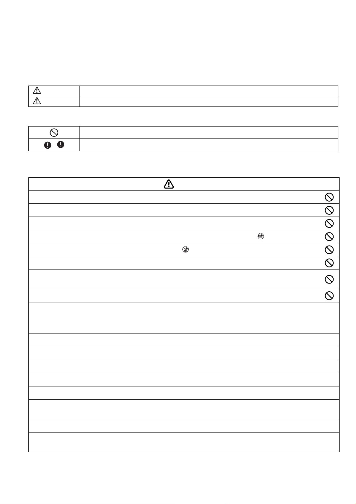
1. Safety Precautions
Read the following “SAFETY PRECAUTIONS” carefully before installation.
Electrical work must be installed by a licensed electrician. Be sure to use the correct rating of the power plug and main circuit
for the model to be installed.
The caution items stated here must be followed because these important contents are related to safety. The meaning of each
indication used is as below. Incorrect installation due to ignoring of the instruction will cause harm or damage, and the
seriousness is classified by the following indications.
WARNING
CAUTION
The items to be followed are classified by the symbols:
Carry out test running to confirm that no abnormality occurs after the installation. Then, explain to user the operation, care
and maintenance as stated in instructions. Please remind the customer to keep the operating instructions for future reference.
This indication shows the possibility of causing death or serious injury.
This indication shows the possibility of causing injury or damage to properties only.
Symbol with white background denotes item that is PROHIBITED.
Symbol with dark background denotes item that must be carried out.
WARNING
Do not install outdoor unit near handrail of veranda. When installing air-conditioner unit on veranda of a high rise building, child
1.
may climb up to outdoor unit and cross over the handrail causing an accident.
Do not use unspecified cord, modified cord, joint cord or extension cord for power supply cord. Do not share the single outlet
2.
with other electrical appliances. Poor contact, poor insulation or over current will cause electrical shock or fire.
3. Do not tie up the power supply cord into a bundle by band. Abnormal temperature rise on power supply cord may happen.
4.
Do not insert your fingers or other objects into the unit, high speed rotating fan may cause injury.
5.
Do not sit or step on the unit, you may fall down accidentally.
6. Keep plastic bag (packaging material) away from small children, it may cling to nose and mouth and prevent breathing.
When installing or relocating air conditioner, do not let any substance other than the specified refrigerant, eg. air etc mix into
7.
refrigeration cycle (piping). Mixing of air etc will cause abnormal high pressure in refrigeration cycle and result in explosion,
injury etc.
8. Do not add or replace refrigerant other than specified type. It may cause product damage, burst and injury etc.
For R410A model, use piping, flare nut and tools which is specified for R410A refrigerant. Using of existing (R22) piping, flare nut
and tools may cause abnormally high pressure in the refrigerant cycle (piping), and possibly result in explosion and injury.
9.
Thickness for copper pipes used with R410A must be more than 1/32" (0.8 mm). Never use copper pipes thinner than
1/32" (0.8 mm).
It is desirable that the amount of residual oil less than 0.0008 oz/ft (40 mg/10 m).
Engage authorized dealer or specialist for installation. If installation done by the user is incorrect, it will cause water leakage, electrical
10.
shock or fire.
11. Install according to this installation instructions strictly. If installation is defective, it will cause water leakage, electrical shock or fire.
Use the attached accessories parts and specified parts for installation. Otherwise, it will cause the set to fall, water leakage, fire or
12.
electrical shock.
Install at a strong and firm location which is able to withstand the set’s weight. If the strength is not enough or installation is not properly
13.
done, the set will drop and cause injury.
For installation work, follow all electrical, building, plumbing, local codes, regulations and these installation instructions. If electrical circuit
14.
capacity is not enough or a defect is found in electrical work, it will cause electrical shock or fire.
Do not use spliced wires for indoor/outdoor connection cable. Use the specified indoor/outdoor connection cable, refer to instruction
15.
CONNECT THE CABLE TO THE INDOOR/OUTDOOR UNIT and connect tightly for indoor/outdoor connection. Clamp the cable so that
no external force will have impact on the terminal. If connection or fixing is not perfect, it will cause heat-up or fire at the connection.
Wire routing must be properly arranged so that control board cover is fixed properly. If control board cover is not fixed perfectly, it will
16.
cause fire or electrical shock.
This equipment must installed with an Earth Leakage Circuit Breaker (ELCB) or Ground Fault Current Interrupter (GFCI) or Appliance
17.
Leakage Current Interrupter (ALCI) that has been certified by an NRTL Certified Testing Agency and that is suitable for the voltages and
amperages involved. Otherwise, if may cause electrical shock and fire in case of equipment breakdown.
3
Page 4
During installation, install the refrigerant piping properly before running the compressor. Operation of compressor without fixing
18.
refrigeration piping and valves at opened condition will cause suck-in of air, abnormal high pressure in refrigeration cycle and result in
explosion, injury etc.
During pump down operation, stop the compressor before removing the refrigeration piping. Removal of refrigeration piping while
19.
compressor is operating and valves are opened will cause suck-in of air, abnormal high pressure in refrigeration cycle and result in
explosion, injury etc.
Tighten the flare nut with torque wrench according to specified method. If the flare nut is over-tightened, after a long period, the flare
20.
may break and cause refrigerant gas leakage.
After completion of installation, confirm there is no leakage of refrigerant gas. It may generate toxic gas when the refrigerant comes into
21.
contact with fire.
22. Ventilate if there is refrigerant gas leakage during operation. It may cause toxic gas when the refrigerant comes into contact with fire.
This equipment must be properly earthed. Earth line must not be connected to gas pipe, water pipe, earth of lightning rod and telephone.
23.
Otherwise, it may cause electrical shock in case of equipment breakdown or insulation breakdown.
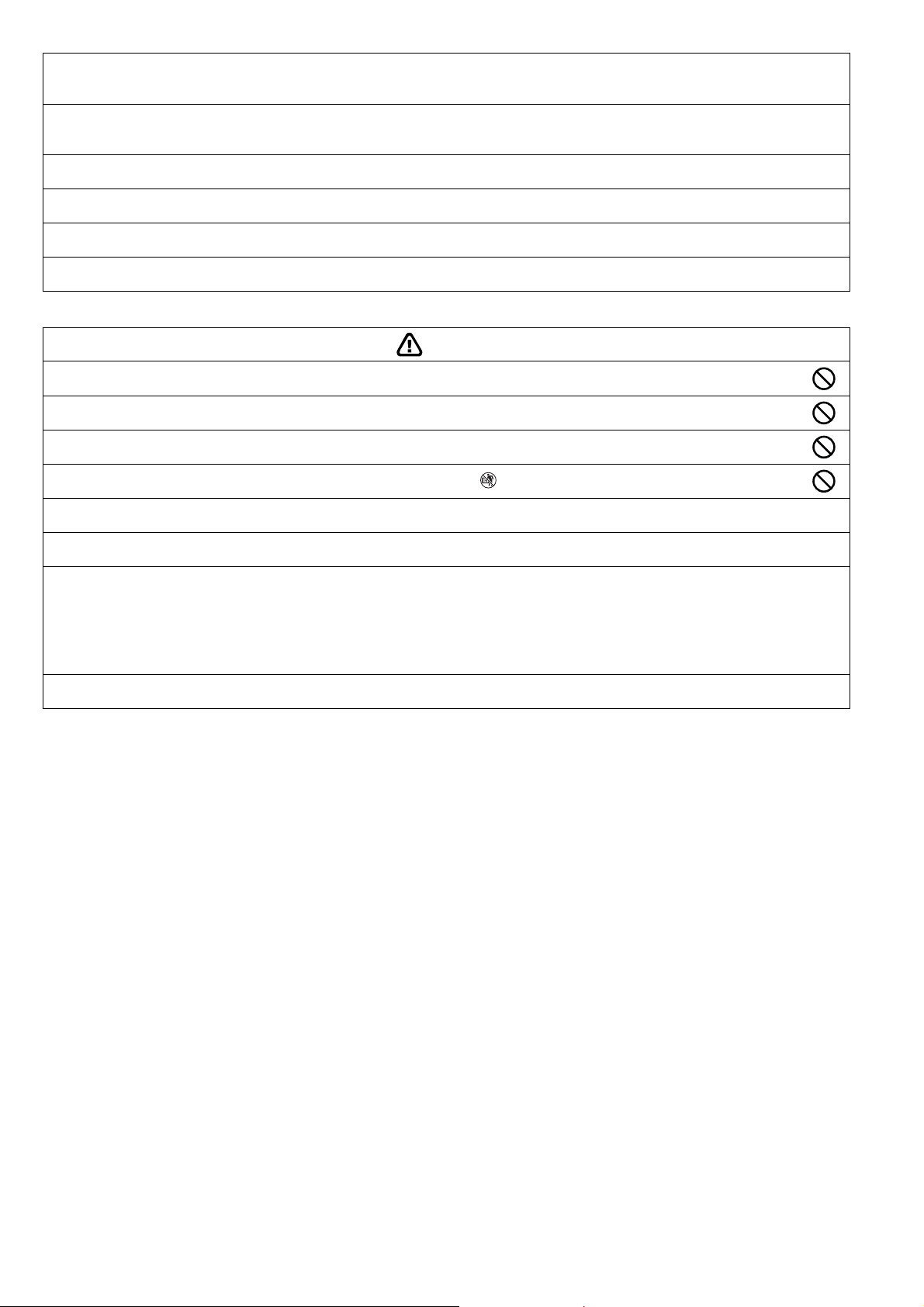
CAUTION
Do not install the unit at place where leakage of flammable gas may occur. In case gas leaks and accumulates at surrounding
1.
of the unit, it may cause fire.
Do not release refrigerant during piping work for installation, re-installation and during repairing a refrigeration parts. Take care
2.
of the liquid refrigerant, it may cause frostbite.
3. Do not install this appliance in a laundry room or other location where water may drip from the ceiling, etc.
4.
Do not touch the sharp aluminium fin, sharp parts may cause injury.
Carry out drainage piping as mentioned in installation instructions. If drainage is not perfect, water may enter the room and damage the
5.
furniture.
6. Select an installation location which is easy for maintenance.
Power supply connection to the room air conditioner.
Power supply cord shall be UL listed or CSA approved 3 conductor with minimum AWG14 (E9SD3UAW, E12SD3UAW) and AWG12
(E18SD3UAW) wires.
7.
Power supply point should be in an easily accessible place for power disconnection in case of emergency.
In some countries, permanent connection of this air conditioner to the power supply is prohibited.
Fix power supply connection to a circuit breaker for permanent connection.
Use NRTL approved fuse or circuit breaker (rating refers to name plate) for permanent connection.
Installation work.
8.
It may take two people to carry out the installation work.
4
Page 5
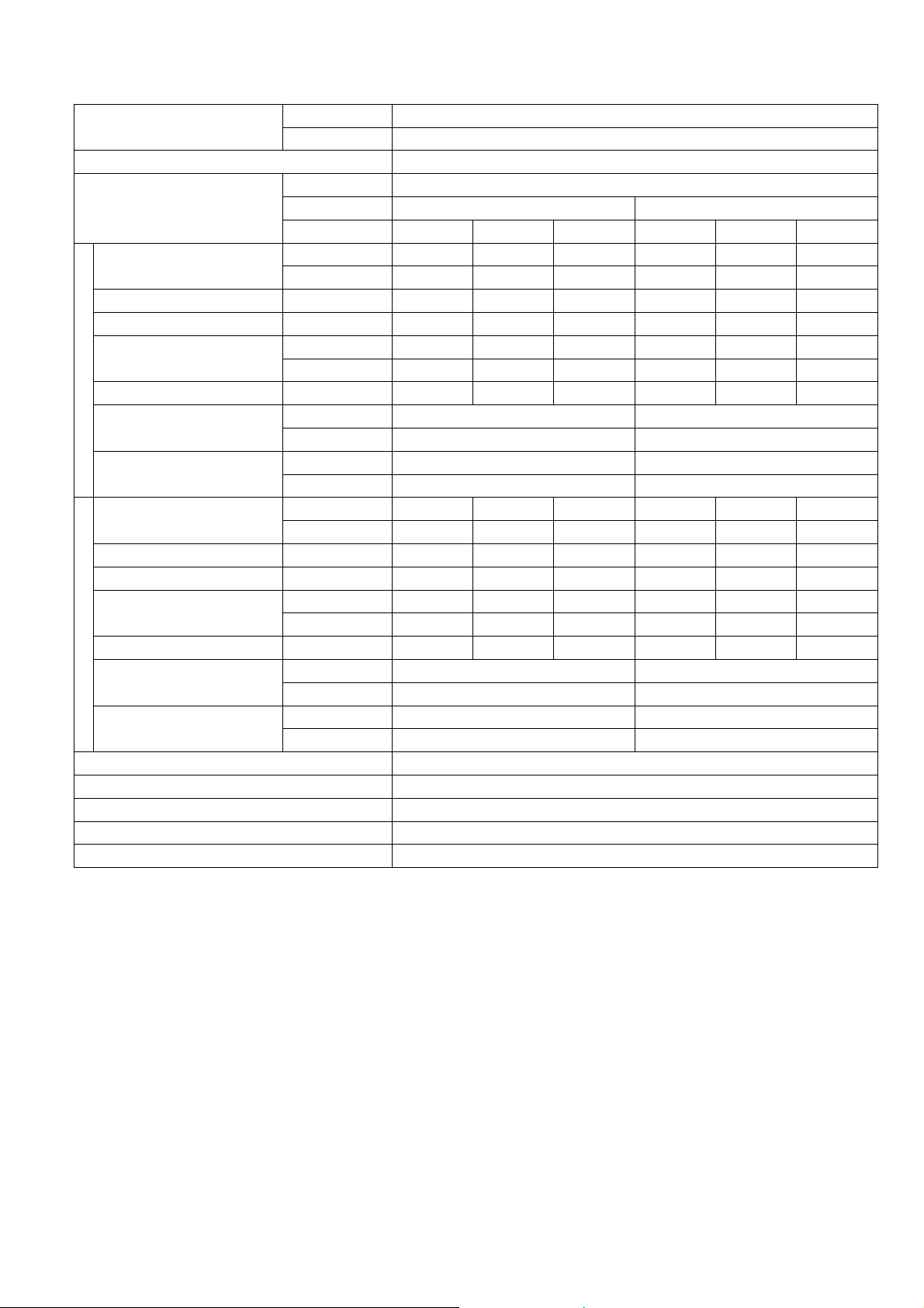
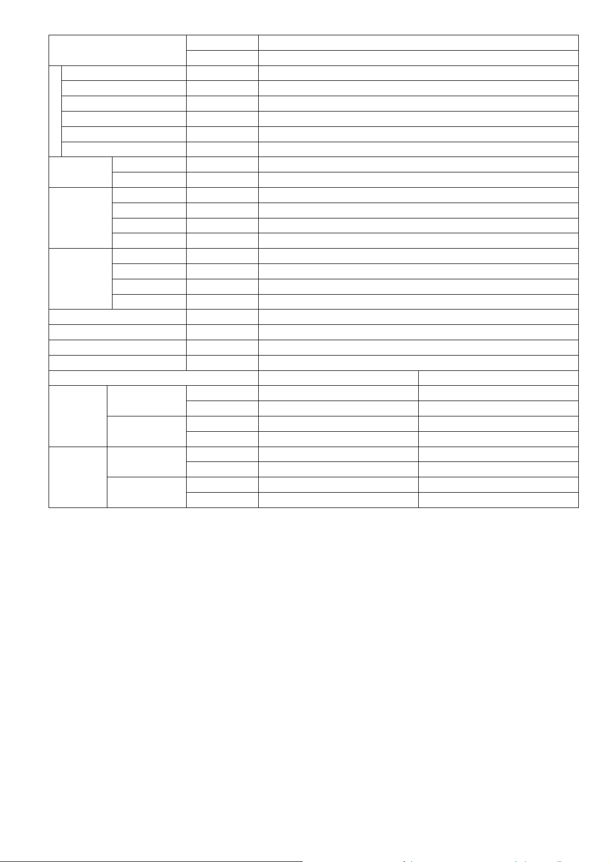
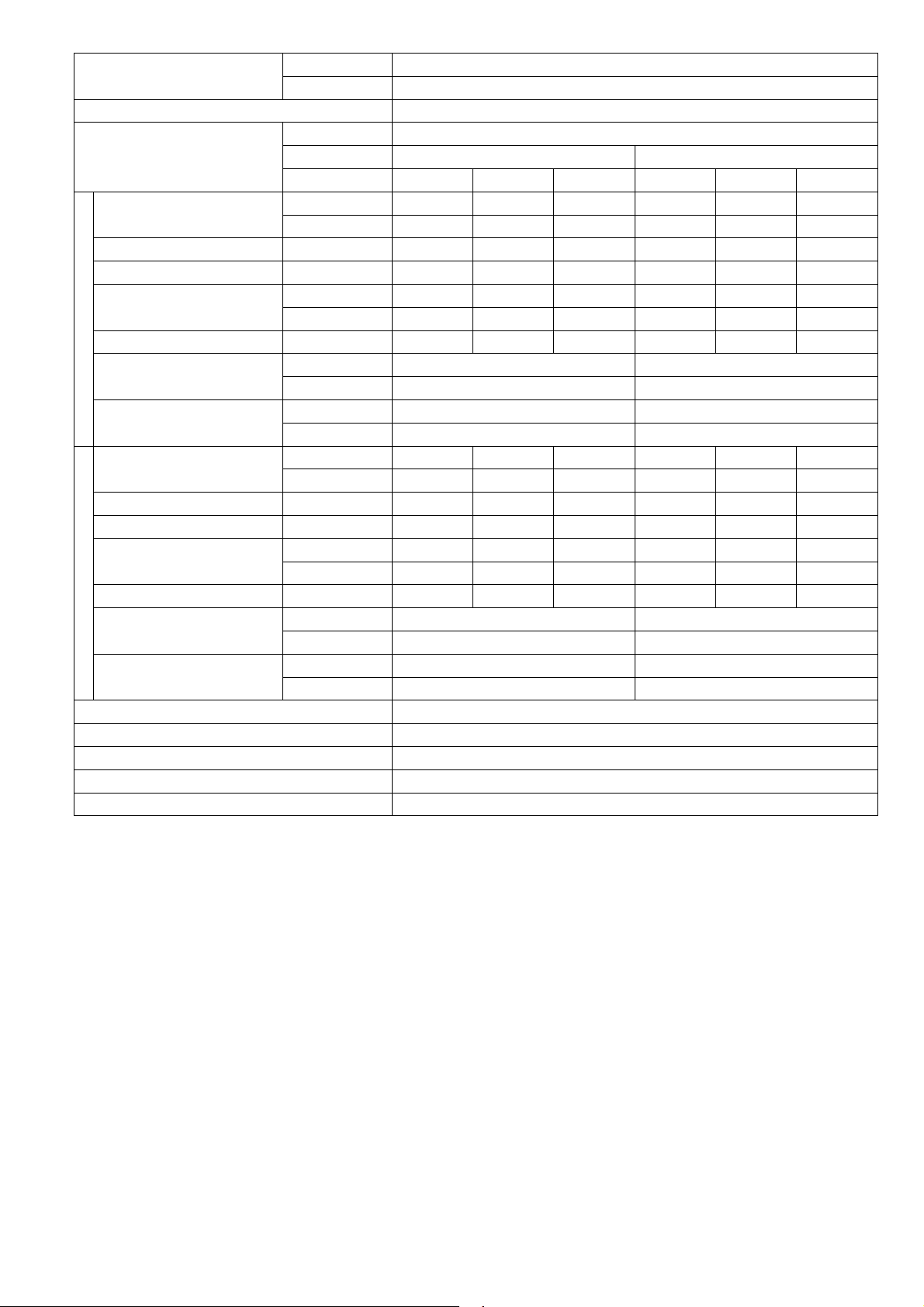
2. Specifications
MODEL
Performance Test Condition ARI
Power Supply
Capacity
Running Current A - 3.6 - - 3.2 -
Input Power W 250 690 850 250 690 850
EER
Cooling
Heating
Power Factor % - 92 - - 94 -
Indoor Noise (H / L / QLo)
Outdoor Noise (H / L / QLo)
Capacity
Running Current A - 5.7 - - 5.1 -
Input Power W 200 1.12k 1.50k 200 1.12k 1.50k
COP
Power Factor % - 96 - - 97 -
Indoor Noise (H / L / QLo)
Outdoor Noise (H / L / QLo)
Min Circuit Ampacity 15.00
Max. Overcurrent Protection 15.00
Max Current (A) / Max Input Power (W) 7.0 / 1.57k
Starting Current (A) 5.70
SEER/HSPF 20.50 / 10.00
INDOOR CS-E9SD3UAW
OUTDOOR CU-E9SD3UA
Phase, Hz Single, 60
V 208 230
Min. Mid. Max. Min. Mid. Max.
kW 1.20 2.64 3.00 1.20 2.64 3.00
BTU/h 4100 9000 10200 4100 9000 10200
W/W 4.80 3.82 3.53 4.80 3.82 3.53
BTU/hW 16.40 13.00 12.00 16.40 13.00 12.00
dB-A 35 / 28 / 25 35 / 28 / 25
Power Level dB 51 / - / - 51 / - / -
dB-A 48 / - / - 48 / - / -
Power Level dB 63 / - / - 63 / - / -
kW 1.20 3.51 4.14 1.20 3.51 4.14
BTU/h 4100 12000 14100 4100 12000 14100
W/W 6.00 3.12 2.76 6.00 3.12 2.76
BTU/hW 20.50 10.70 9.40 20.50 10.70 9.40
dB-A 35 / 28 / 25 35 / 28 / 25
Power Level dB 51 / - / - 51 / - / -
dB-A 50 / - / - 50 / - / -
Power Level dB 65 / - / - 65 / - / -
5
Page 6

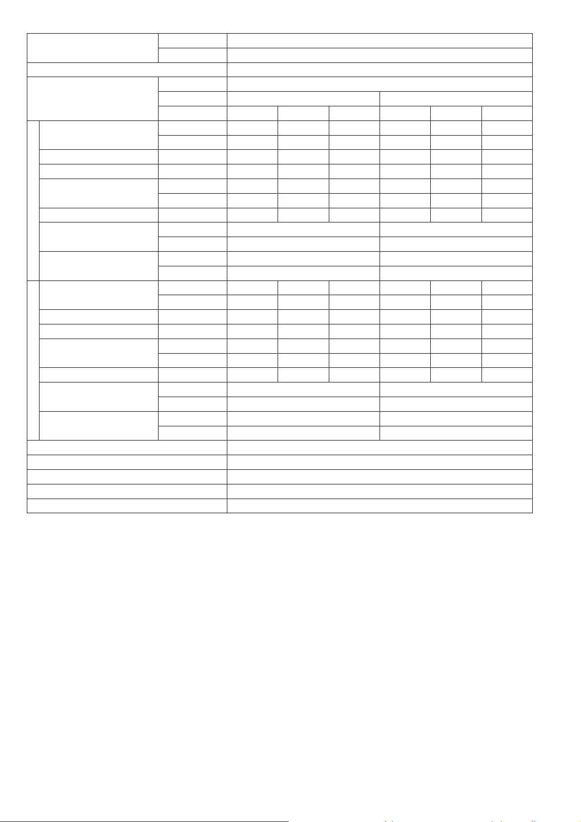
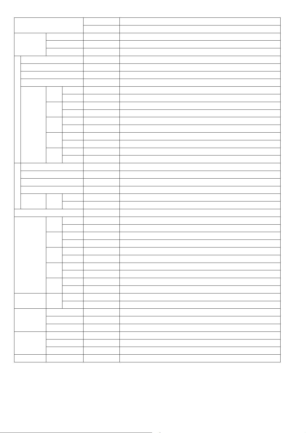
MODEL
INDOOR
OUTDOOR CU-E9SD3UA
CS-E9SD3U
Type Hermetic Motor / Rotary
Compressor
Motor Type Brushless (4-poles)
Output Power 700
Type Sirocco
Material GFZ010A / GF20
Motor Type DC Motor (8-poles)
Output Power W 51
Cool rpm
Heat rpm 800
Cool rpm 940
Heat rpm 880
Cool rpm
1120
Heat rpm 1090
Cool rpm
1300
Heat rpm 1300
Cool rpm
Heat rpm
1380
1380
Indoor Fan
Speed
QLo
Lo
Me
Hi
SHi
Type Propeller Fan
Material PP
Motor Type DC Motor (8-poles)
Output Power W 40
Outdoor Fan
Speed Hi
Cool rpm 830
Heat rpm 780
Moisture Removal L/h (Pt/h) 0.6 (1.3)
3
QLo
Lo
Indoor Airflow
Me
Hi
SHi
Outdoor Airflow Hi
Cool m
Heat m3/min (ft3/min) 8.50 (300)
Cool m
Heat m3/min (ft3/min) 9.30 (328)
Cool m
Heat m3/min (ft3/min) 11.40 (403)
Cool m
Heat m3/min (ft3/min) 13.50 (475)
Cool m
Heat m3/min (ft3/min) 14.30 (505)
Cool m
Heat m3/min (ft3/min) 31.0 (1095)
/min (ft3/min) 9.30 (328)
3
/min (ft3/min) 9.90 (350)
3
/min (ft3/min) 11.70 (413)
3
/min (ft3/min) 13.50 (475)
3
/min (ft3/min) 14.30 (505)
3
/min (ft3/min) 31.0 (1095)
Control Device Expansion Valve
Refrigeration
Cycle
Refrigerant Oil cm
3
FV50S (320)
Refrigerant Type g (oz) R410A, 980 (34.6)
Height (I/D / O/D) mm (inch) 200 (7-7/8) / 542 (21-11/32)
Dimension
Width (I/D / O/D) mm (inch) 750 (29-17/32) / 780 (30-23/32)
Depth (I/D / O/D) mm (inch) 640 (25-7/32) / 289 (11-13/32)
Weight Net (I/D / O/D) kg (lb) 19 (42) / 37 (82)
AW
880
6
Page 7
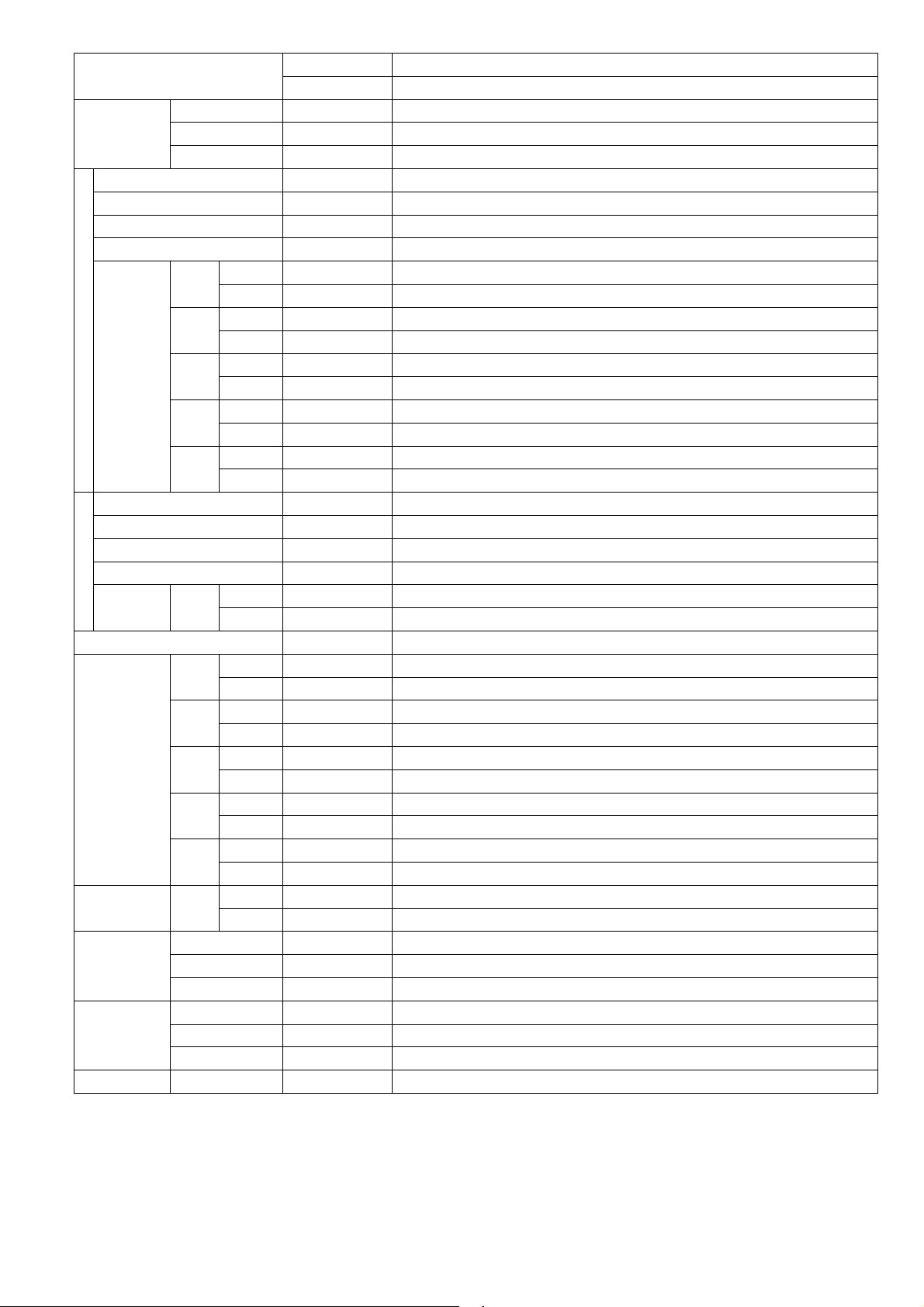
MODEL
Pipe Diameter (Liquid / Gas) mm (inch) 6.35 (1/4) / 9.52 (3/8)
Standard Length m (ft) 7.5 (24.6)
Length Range (min - max) m (ft) 3 (9.8) ~ 20 (65.6)
I/D & O/D Height Different m (ft) 15 (49.2)
Piping
Additional Gas Amount g/m (oz/ft) 20 (0.2)
Length for Additional Gas m (ft) 7.5 (24.6)
Drain Hose
Indoor Heat
Exchanger
Outdoor Heat
Exchanger
Power Supply Cord A Nil
Protection Device Electronic Control
Indoor
Operation
Range
Outdoor
Operation
Range
Inner Diameter mm/inch 16 / 0.63
Length mm/inch 117.5 / 4.63
Fin Material Aluminium (Pre Coat)
Fin Type Slit Fin
Row x Stage x FPI 3 x 12 x 18
Size (W x H x L) mm 590 x 282 x 38.1
Fin Material Aluminium (Blue Coat)
Fin Type Corrugated Fin
Row x Stage x FPI 2 x 24 x 17
Size (W x H x L) mm 36.4 x 504 x 713:684
Power Supply Outdoor Power Supply
Thermostat Electronic Control
Cooling
Heating
Cooling
Heating
INDOOR
OUTDOOR CU-E9SD3UA
Dry Bulb Wet Bulb
Maximum °C/°F 32 / 89.6 23 / 73.4
Minimum °C/°F 16 / 60.8 11 / 51.8
Maximum °C/°F 30 / 86.0
Minimum °C/°F 16 / 60.8 - / -
Maximum °C/°F 46 / 114.8 26 / 78.8
Minimum °C/°F -17.8 / 0 - / -
Maximum °C/°F 24 / 75.2 18 / 64.4
Minimum °C/°F -20 / -4 -21 / -5.8
CS-E9SD3U
AW
- / -
1.
Cooling capacities are based on indoor temperature of 27°C Dry Bulb (80.6°F Dry Bulb), 19.0°C Wet Bulb (66.2°F Wet Bulb) and outdo
temperatu
2.
Heating capacities are based on indoor temperature of 20°C Dry Bulb (68°F Dry Bulb) and outdoor air temperature of 7°C Dry Bulb
(44.6°F Dry Bulb), 6°C Wet Bulb (42.8°F Wet Bulb)
3 Heating low temperature capacity, Input Power and COP measured at 230 V, indoor temperature 20°C (68°F), outdoor 2/1°C (35°F/33.8°F)
4 Heating extreme low temperature capacity, Input Power and COP measured at 230 V indoor temperature 20°C (68°F), outdoor -7/-8°C
(19.4°F/17.6°F)
5.
Standby power consumption ≤0.7W (when switched OFF by remote control, except under self protection control).
Specifications are subjected to change without notice for further improvement.
6.
re of 35°C Dry Bulb (95°F Dry Bulb), 24°C Wet Bulb (75.2°F Wet Bulb)
or air
7
Page 8
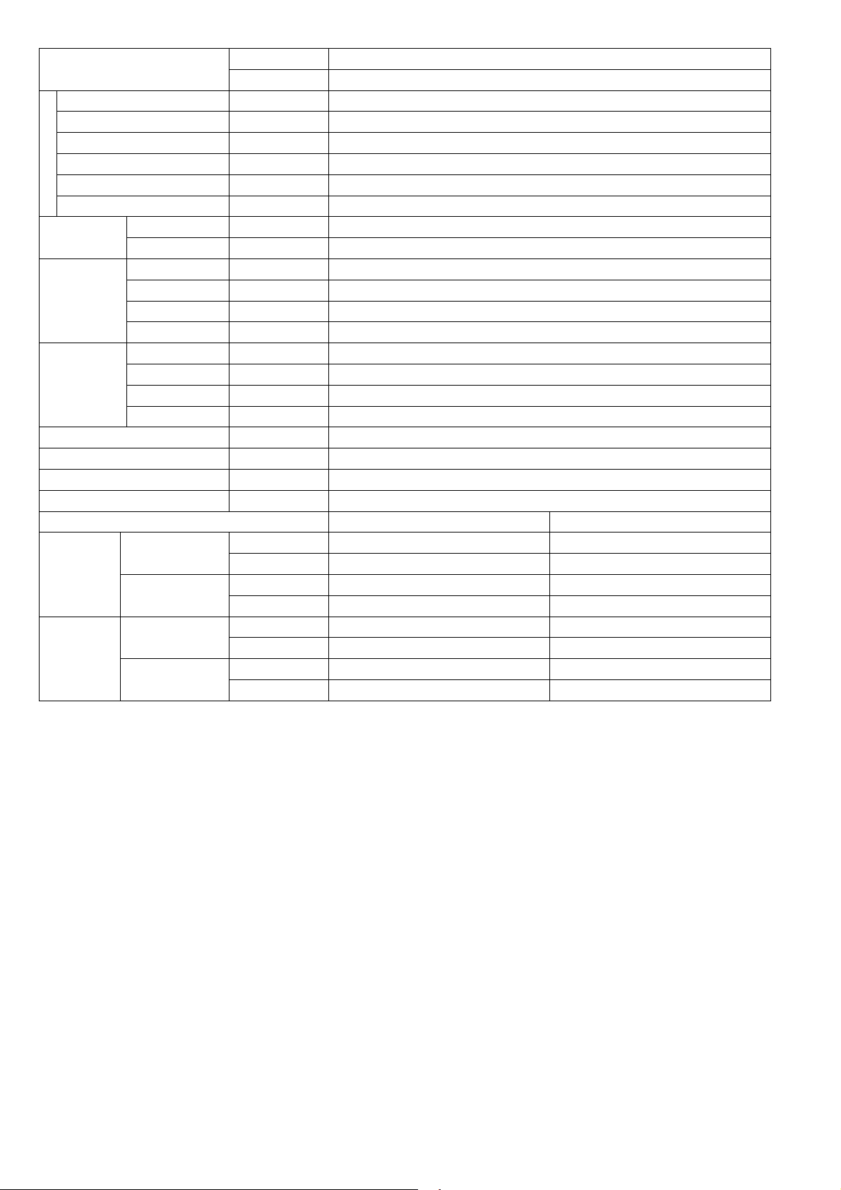
MODEL
Performance Test Condition ARI
Power Supply
Capacity
Running Current A - 4.7 - - 4.2 -
Input Power W 250 920 1.15k 250 920 1.15k
EER
Cooling
Heating
Power Factor % - 94 - - 95 -
Indoor Noise (H / L / QLo)
Outdoor Noise (H / L / QLo)
Capacity
Running Current A - 6.3 - - 5.6 -
Input Power W 200 1.25k 1.71k 200 1.25k 1.71k
COP
Power Factor % - 95 - - 97 -
Indoor Noise (H / L / QLo)
Outdoor Noise (H / L / QLo)
Min Circuit Ampacity 15.00
Max. Overcurrent Protection 15.00
Max Current (A) / Max Input Power (W) 7.8 / 1.71k
Starting Current (A) 6.30
SEER/HSPF 20.00 / 10.00
INDOOR
OUTDOOR CU-E12SD3UA
Phase, Hz Single, 60
V 208 230
Min. Mid. Max. Min. Mid. Max.
kW 1.20 3.36 3.90 1.20 3.36 3.90
BTU/h 4100 11500 13300 4100 4100 13300
W/W 4.80 3.64 3.39 4.80 3.64 3.39
BTU/hW 16.40 12.50 11.55 16.40 12.50 11.55
dB-A 35 / 28 / 25 35 / 28 / 25
Power Level dB 51 / - / - 51 / - / -
dB-A 49 / - / - 49 / - / -
Power Level dB 64 / - / - 64 / - / -
kW 1.20 4.05 4.77 1.20 4.05 4.77
BTU/h 4100 13800 16300 4100 13800 16300
W/W 6.00 3.24 2.79 6.00 3.24 2.79
BTU/hW 20.50 11.00 9.50 20.50 11.00 9.50
dB-A 35 / 28 / 25 35 / 28 / 25
Power Level dB 51 / - / - 51 / - / -
dB-A 51 / - / - 51 / - / -
Power Level dB 66 / - / - 66 / - / -
CS-E12SD3UAW
8
Page 9
MODEL
INDOOR
OUTDOOR CU-E12SD3UA
CS-E12SD3UAW
Type Hermetic Motor / Rotary
Compressor
Motor Type Brushless (4-poles)
Output Power 700
Type Sirocco
Material GFZ010A / GF20
Motor Type DC Motor (8-poles)
Output Power W 51
Cool rpm
Heat rpm 800
Cool rpm 940
Heat rpm 880
Cool rpm
1120
Heat rpm 1090
Cool rpm
1300
Heat rpm 1300
Cool rpm
Heat rpm
1430
1430
Indoor Fan
Speed
QLo
Lo
Me
Hi
SHi
Type Propeller Fan
Material PP
Motor Type DC Motor (8-poles)
Output Power W 40
Outdoor Fan
Speed Hi
Cool rpm 830
Heat rpm 820
Moisture Removal L/h (Pt/h) 0.8 (1.7)
3
QLo
Lo
Indoor Airflow
Me
Hi
SHi
Outdoor Airflow Hi
Cool m
Heat m3/min (ft3/min) 8.50 (300)
Cool m
Heat m3/min (ft3/min) 9.30 (328)
Cool m
Heat m3/min (ft3/min) 11.40 (403)
Cool m
Heat m3/min (ft3/min) 13.50 (475)
Cool m
Heat m3/min (ft3/min) 14.80 (523)
Cool m
Heat m3/min (ft3/min) 31.2 (1100)
/min (ft3/min) 9.30 (328)
3
/min (ft3/min) 9.90 (350)
3
/min (ft3/min) 11.70 (413)
3
/min (ft3/min) 13.50 (475)
3
/min (ft3/min) 14.80 (523)
3
/min (ft3/min) 31.2 (1100)
Control Device Expansion Valve
Refrigeration
Cycle
Refrigerant Oil cm
3
FV50S (320)
Refrigerant Type g (oz) R410A, 1.08k (38.1)
Height (I/D / O/D) mm (inch) 200 (7-7/8) / 542 (21-11/32)
Dimension
Width (I/D / O/D) mm (inch) 750 (29-17/32) / 780 (30-23/32)
Depth (I/D / O/D) mm (inch) 640 (25-7/32) / 289 (11-13/32)
Weight Net (I/D / O/D) kg (lb) 19 (42) / 37 (82)
880
9
Page 10
MODEL
Pipe Diameter (Liquid / Gas) mm (inch) 6.35 (1/4) / 12.70 (1/2)
Standard Length m (ft) 7.5 (24.6)
Length Range (min - max) m (ft) 3 (9.8) ~ 20 (65.6)
I/D & O/D Height Different m (ft) 15 (49.2)
Piping
Additional Gas Amount g/m (oz/ft) 20 (0.2)
Length for Additional Gas m (ft) 7.5 (24.6)
Drain Hose
Indoor Heat
Exchanger
Outdoor Heat
Exchanger
Power Supply Cord A Nil
Protection Device Electronic Control
Indoor
Operation
Range
Outdoor
Operation
Range
1. Cooling capacities are based on indoor temperature of 27°C Dry Bulb (80.6°F Dry Bulb), 19.0°C Wet Bulb (66.2°F Wet Bulb) and outdoor air
temperature of 35°C Dry Bulb (95°F Dry Bulb), 24°C Wet Bulb (75.2°F Wet Bulb)
2. Heating capacities are based on indoor temperature of 20°C Dry Bulb (68°F Dry Bulb) and outdoor air temperature of 7°C Dry Bulb
(44.6°F Dry Bulb), 6°C Wet Bulb (42.8°F Wet Bulb)
3 Heating low temperature capacity, Input Power and COP measured at 230 V, indoor temperature 20°C (68°F), outdoor 2/1°C (35°F/33.8°F)
4 Heating extreme low temperature capacity, Input Power and COP measured at 230 V indoor temperature 20°C (68°F), outdoor -7/-8°C
(19.4°F/17.6°F)
5. Standby power consumption ≤0.7W (when switched OFF by remote control, except under self protection control).
6. Specifications are subjected to change without notice for further improvement.
Inner Diameter mm/inch 16 / 0.63
Length mm/inch 117.5 / 4.63
Fin Material Aluminium (Pre Coat)
Fin Type Slit Fin
Row x Stage x FPI 3 x 12 x 18
Size (W x H x L) mm 590 x 282 x 38.1
Fin Material Aluminium (Blue Coat)
Fin Type Corrugated Fin
Row x Stage x FPI 2 x 24 x 17
Size (W x H x L) mm 36.4 x 504 x 824:794
Power Supply Outdoor Power Supply
Thermostat Electronic Control
Dry Bulb Wet Bulb
Cooling
Heating
Cooling
Heating
INDOOR CS-E12SD3UAW
OUTDOOR CU-E12SD3UA
Maximum °C/°F 32 / 89.6 23 / 73.4
Minimum °C/°F 16 / 60.8 11 / 51.8
Maximum °C/°F 30 / 86.0 - / -
Minimum °C/°F 16 / 60.8 - / -
Maximum °C/°F 46 / 114.8 26 / 78.8
Minimum °C/°F -17.8 / 0 - / -
Maximum °C/°F 24 / 75.2 18 / 64.4
Minimum °C/°F -20 / -4 -21 / -5.8
10
Page 11
MODEL
Performance Test Condition ARI
Power Supply
Capacity
Running Current A - 8.5 - - 7.6 -
Input Power W 430 1.58k 1.82k 430 1.58k 1.82k
EER
Cooling
Heating
Power Factor % - 89 - - 90 -
Indoor Noise (H / L / QLo)
Outdoor Noise (H / L / QLo)
Capacity
Running Current A - 9.8 - - 8.7 -
Input Power W 380 1.83k 2.18k 380 1.83k 2.18k
COP
Power Factor % - 90 - - 91 -
Indoor Noise (H / L / QLo)
Outdoor Noise (H / L / QLo)
Min Circuit Ampacity 20.0
Max. Overcurrent Protection 25.0
Max Current (A) / Max Input Power (W) 13.7 / 3.06k
Starting Current (A) 9.80
INDOOR CS-E18SD3UAW
OUTDOOR CU-E18SD3UA
Phase, Hz Single, 60
V 208 230
Min. Mid. Max. Min. Mid. Max.
kW 1.70 5.04 5.70 1.70 5.04 5.70
BTU/h 5800 17200 19400 5800 17200 19400
W/W 3.95 3.18 3.13 3.95 3.18 3.13
BTU/hW 13.45 10.85 10.65 13.45 10.85 10.65
dB-A 41 / 30 / 27 41 / 30 / 27
Power Level dB 57 / - / - 57 / - / -
dB-A 49 / - / - 49 / - / -
Power Level dB 63 / - / - 63 / - / -
kW 1.70 6.09 7.10 1.70 6.09 7.10
BTU/h 5800 20800 24200 5800 20800 24200
W/W 4.47 3.32 3.26 4.47 3.32 3.26
BTU/hW 15.25 11.35 11.10 15.25 11.35 11.10
dB-A 41 / 32 / 29 41 / 32 / 29
Power Level dB 57 / - / - 57 / - / -
dB-A 51 / - / - 51 / - / -
Power Level dB 65 / - / - 65 / - / -
SEER/HSPF 16.50 / 8.50
11
Page 12
MODEL
INDOOR CS-E18SD3UAW
OUTDOOR CU-E18SD3UA
Type Hermetic Motor / Rotary
Compressor
Motor Type Brushless (4-poles)
Output Power 1.70k
Type Sirocco
Material GFZ010A / GF20
Motor Type DC Motor (8-poles)
Output Power W 51
Cool rpm 920
Heat rpm 920
Cool rpm 980
Heat rpm 1000
Cool rpm 1230
Heat rpm 1240
Cool rpm 1480
Heat rpm 1480
Cool rpm 1530
Heat rpm 1530
Indoor Fan
Speed
QLo
Lo
Me
Hi
SHi
Type Propeller Fan
Material PP
Motor Type DC Motor (8-poles)
Output Power W 60
Outdoor Fan
Speed Hi
Cool rpm 700
Heat rpm 700
Moisture Removal L/h (Pt/h) 2.2 (4.6)
3
/min (ft3/min) 9.70 (342)
3
/min (ft3/min) 10.30 (364)
3
/min (ft3/min) 12.80 (452)
3
/min (ft3/min) 15.30 (540)
3
/min (ft3/min) 15.80 (558)
3
/min (ft3/min) 54.5 (1925)
QLo
Lo
Indoor Airflow
Me
Hi
SHi
Outdoor Airflow Hi
Cool m
Heat m3/min (ft3/min) 9.70 (342)
Cool m
Heat m3/min (ft3/min) 10.30 (364)
Cool m
Heat m3/min (ft3/min) 12.80 (452)
Cool m
Heat m3/min (ft3/min) 15.30 (540)
Cool m
Heat m3/min (ft3/min) 15.80 (558)
Cool m
Heat m3/min (ft3/min) 54.5 (1925)
Control Device Expansion Valve
Refrigeration
Cycle
Refrigerant Oil cm3 FV50S (800)
Refrigerant Type g (oz) R410A, 1.60k (56.5)
Height (I/D / O/D) mm (inch) 200 (7-7/8) / 795 (31-5/16)
Dimension
Width (I/D / O/D) mm (inch) 750 (29-17/32) / 875 (34-15/32)
Depth (I/D / O/D) mm (inch) 640 (25-7/32) / 320 (12-5/8)
Weight Net (I/D / O/D) kg (lb) 19 (42) / 60 (132)
12
Page 13

MODEL
Pipe Diameter (Liquid / Gas) mm (inch) 6.35 (1/4) / 12.70 (1/2)
Standard Length m (ft) 7.5 (24.6)
Length Range (min - max) m (ft) 3 (9.8) ~ 30.5 (100.0)
I/D & O/D Height Different m (ft) 15 (49.2)
Piping
Additional Gas Amount g/m (oz/ft) 25 (0.3)
Length for Additional Gas m (ft) 10 (32.8)
Drain Hose
Indoor Heat
Exchanger
Outdoor Heat
Exchanger
Power Supply Cord A Nil
Protection Device Electronic Control
Indoor
Operation
Range
Outdoor
Operation
Range
1. Cooling capacities are based on indoor temperature of 27°C Dry Bulb (80.6°F Dry Bulb), 19.0°C Wet Bulb (66.2°F Wet Bulb) and outdoor air
temperature of 35°C Dry Bulb (95°F Dry Bulb), 24°C Wet Bulb (75.2°F Wet Bulb)
2. Heating capacities are based on indoor temperature of 20°C Dry Bulb (68°F Dry Bulb) and outdoor air temperature of 7°C Dry Bulb
(44.6°F Dry Bulb), 6°C Wet Bulb (42.8°F Wet Bulb)
3 Heating low temperature capacity, Input Power and COP measured at 230 V, indoor temperature 20°C (68°F), outdoor 2/1°C (35°F/33.8°F)
4 Heating extreme low temperature capacity, Input Power and COP measured at 230 V indoor temperature 20°C (68°F), outdoor -7/-8°C
(19.4°F/17.6°F)
5. Standby power consumption ≤0.7W (when switched OFF by remote control, except under self protection control).
6. Specifications are subjected to change without notice for further improvement.
Inner Diameter mm/inch 16 / 0.63
Length mm/inch 117.5 / 4.63
Fin Material Aluminium (Pre Coat)
Fin Type Slit Fin
Row x Stage x FPI 3 x 12 x 18
Size (W x H x L) mm 590 x 282 x 38.1
Fin Material Aluminium (Blue Coat)
Fin Type Corrugated Fin
Row x Stage x FPI 2 x 36 x 19
Size (W x H x L) mm 36.4 x 756 x 869:897
Power Supply Outdoor Power Supply
Thermostat Electronic Control
Dry Bulb Wet Bulb
Cooling
Heating
Cooling
Heating
INDOOR CS-E18SD3UAW
OUTDOOR CU-E18SD3UA
Maximum °C/°F 32 / 89.6 23 / 73.4
Minimum °C/°F 16 / 60.8 11 / 51.8
Maximum °C/°F 30 / 86.0 - / -
Minimum °C/°F 16 / 60.8 - / -
Maximum °C/°F 46 / 114.8 26 / 78.8
Minimum °C/°F -17.8 / 0 - / -
Maximum °C/°F 24 / 75.2 18 / 64.4
Minimum °C/°F -20 / -4 -21 / -5.8
13
Page 14

3. Features
Inverter Technology
o Wider output power range
o Energy saving
o Quick Cooling
o Quick Heating
o More precise temperature control
Environment Protection
o Non-ozone depletion substances refrigerant (R410A)
Long Installation Piping
o Long piping up to 20 meter (E9SD3UA/E12SD3UA)
o Long piping up to 30.5 meter (E18SD3UA)
Easy to use remote control
Quality Improvement
o Random auto restart after power failure for safety restart operation
o Gas leakage protection
o Prevent compressor reverse cycle
o Inner protector to protect compressor
o Noise prevention during soft dry operation
Operation Improvement
o Quiet mode to reduce the indoor unit operating sound
o Powerful mode to reach the desired room temperature quickly
o 24-hour timer setting
Serviceability Improvement
o Breakdown Self Diagnosis function
14
Page 15
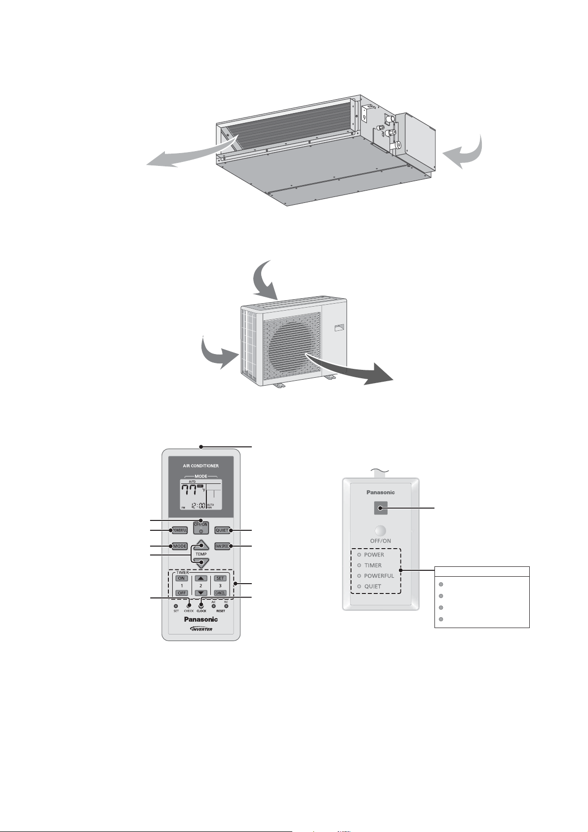
4. Location of Controls and Components
A
A
4.1 Indoor Unit
ir outlet
Air inlet
4.2 Outdoor Unit
ir inlet (side)
4.3 Remote Control
Air inlet (rear)
Air outlet
Transmitter
Remote control receiver
Powerful operation
Temperature setting
OFF/ON
Operation mode
Check
Quiet operation
Fan speed selection
Timer setting
Clock setting
Indicator
POWER
TIMER
POWERFUL
QUIET
(Green)
(Orange)
(Orange)
(Orange)
15
Page 16

5. Dimensions
5.1 Indoor Unit
<Front View>
145 (5 - 11/16)
(AIR OUTLET DUCT FLANGE)
<Bottom View>
26 (1 - 1/32)
5 - Ø 3.1 HOLE
(AIR OUTLET DUCT FLANGE)
692 (27 - 1/4)
160 X 4 = 640
96 (3 - 25/32)
2 - Ø 3.1 HOLE
27 (1 - 1/16)
WATER INLET
28 (1-3/32)
<Side View>
84 (3-5/16)
81 (3-3/16)
30 (1-3/16)
10 (3/8)
143 (5-5/8)
80 (3-1/8)
238 (9 - 3/8)
44
(1 - 23/32)
640 (25 - 3/16)
564 (22 - 3/16)
<Back View>
(AIR INLET)
126 (4 - 31/32)
AIR FILTER
40
(1-9/16)
23 (1 - 3/32)
155 ( 6 - 3/32)
120 (4 - 23/32)
750 (29 - 17/32)
824 (32 - 7/16)
904 (35 - 9/16)
680 (26 - 25/32)
(AIR INLET)
14 (17/32)
14 (17/32) 14 (17/32)
194 ( 7 - 5/8)
120 (4 - 23/32)33 (1 - 5/16)
DRAIN PORT (UPPER & LOWER)
150 (5 7/8)
200 ( 7- 7/8)
<Remote Control>
59 (2-5/16)
144.5 (5-11/16)
18 (11/16)
<Remote Control Holder>
87 (3-13/32)
23 (7/8)
23 (7/8) 23 (7/8)
14 (17/32)
220 (8 - 21/32) 220 (8 - 21/32)132 (5 - 3/16) 132 (5 - 3/16)
63.68 (2-1/2)
Unit : mm/inch
16
Page 17
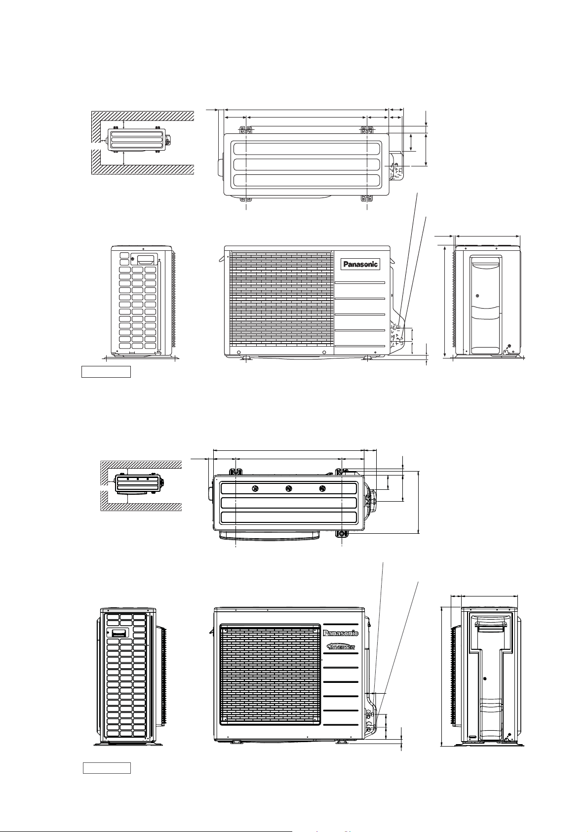
5.2 Outdoor Unit
5.2.1 CU-E9SD3UA CU-E12SD3UA
Space necessary for
installation
10 cm
24.4
(15/16)
<Top View>
(104.7)
(4-3/32)
780 (30-23/32)
570 (22-7/16)
104.9
(4-1/8)
67.6
(2-21/32)
60.5
(2-3/8)
34.5
(1-11/32)
10 cm
100 cm
Anchor Bolt Pitch
320 x 570
Unit : mm/inch
5.2.2 CU-E18SD3UA
Space necessary for
installation
10 cm
10 cm
100 cm
27.5
(1-1/16)
<Front View><Side View>
<Top View>
(131)
(5-5/32)
875 (34-15/32)
613 (24-1/8)
84.8
(3-5/16)
155 (6-3/32)
2-way valve at Liquid side
(High Pressure)
3-way valve at Gas side
(Low Pressure)
<Side View>
289 (11-13/32)
542 (21-11/32)
61.6
69.6
(2-13/32)
(18)
(2-23/32)
11.5 (7/16)
(11/16)
70
(2-3/4)
131
(5-5/32)
82
38
(3-7/32)
152
(1-1/2)
(5-31/32)
Anchor Bolt Pitch
360.5 x 613
Unit: mm/inch
360.5 (14-3/16)
2-way valve at Liquid side
(High Pressure)
3-way valve at Gas side
(Low Pressure)
<Front View><Side View>
64 (2-1/2)
75
(2-15/16)
(25)
(31-32)
70
(2-3/4)
<Side View>
59
(2-5/16)
795 (31-5/16)
320 (12-5/8)
17
Page 18
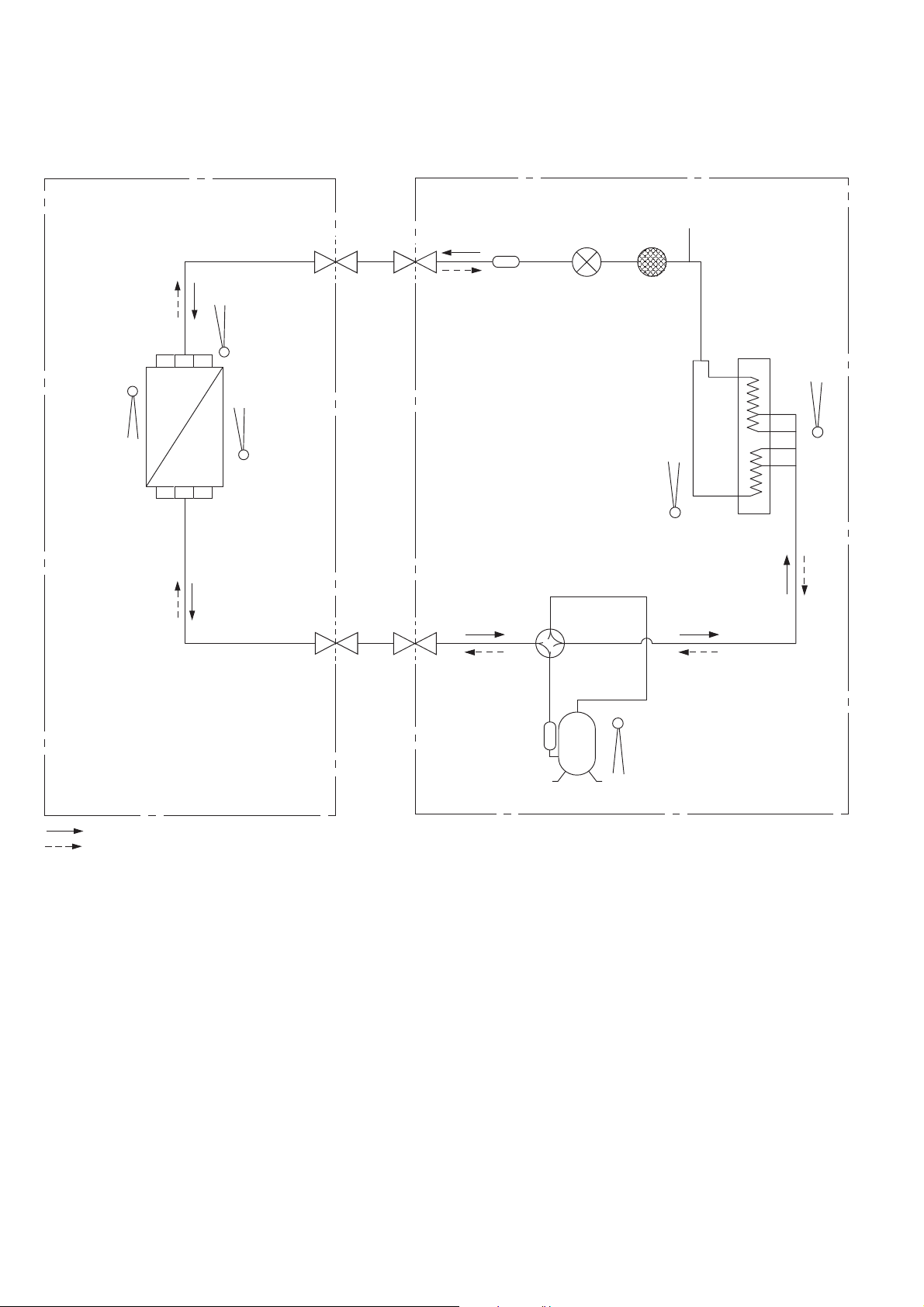
6. Refrigeration Cycle Diagram
6.1 CS-E9SD3UAW CU-E9SD3UA
INDOOR
LIQUID
SIDE
2-WAY
VALV E
INTAKE
TEMP.
SENSOR
HEAT EXCHANGER
(EVAPORATOR)
PIPE
TEMP.
SENSOR 1
PIPE
(INLET)
TEMP.
SENSOR 2
DISCHARGE
MUFFLER
EXPANSION
VALV E
SENSOR
OUTDOOR
PROCESS
TUBE
STRAINER
PIPE
TEMP.
CONDENSER
AIR
TEMP.
SENSOR
COOLING
HEATING
GAS
SIDE
3-WAY
VALV E
4-WAYS VALVE
DISCHARGE
MUFFLER
COMPRESSOR
TEMP. SENSOR
COMPRESSOR
18
Page 19
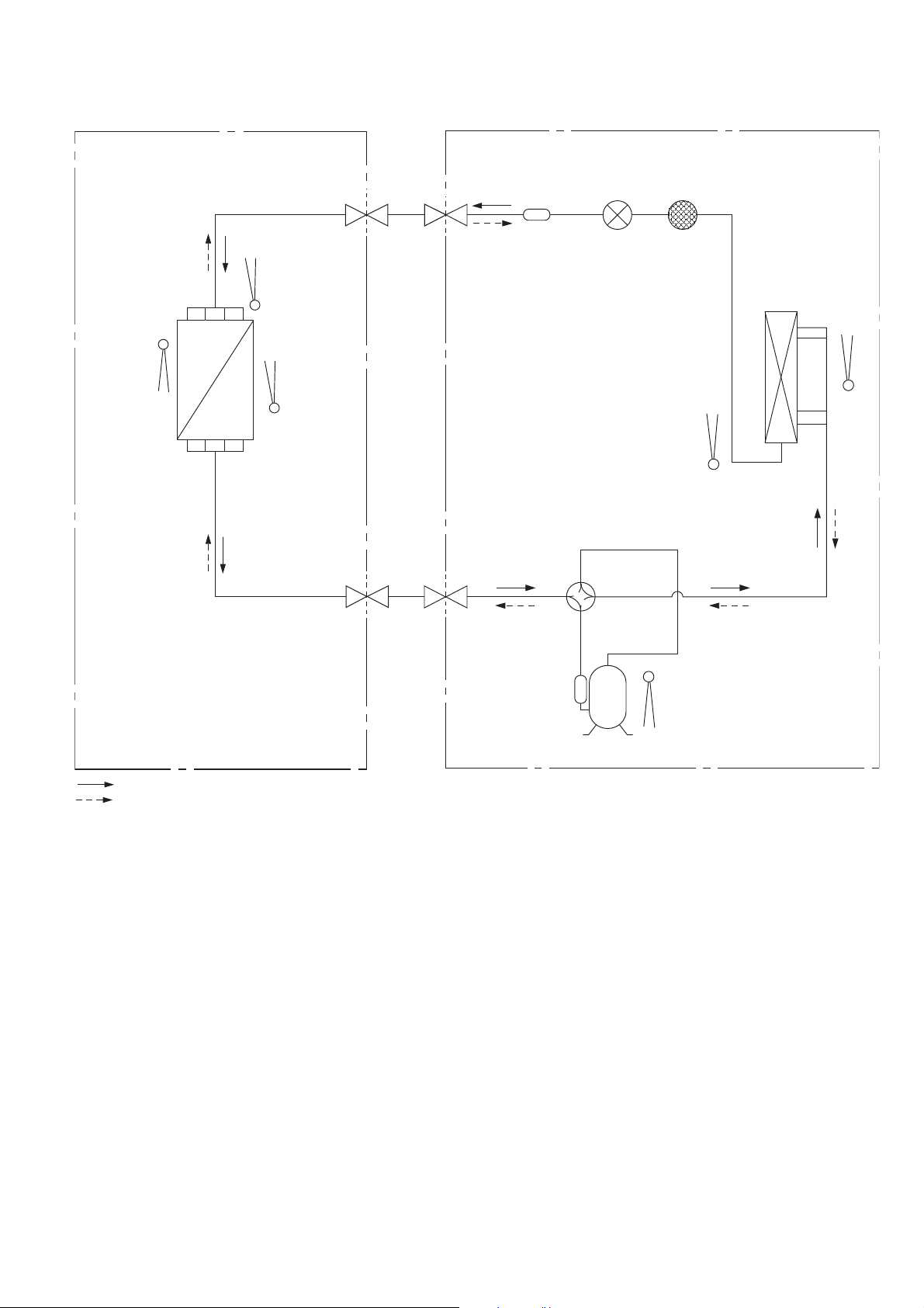
6.2 CS-E12SD3UAW CU-E12SD3UA
INDOOR
OUTDOOR
INTAKE
TEMP.
SENSOR
HEAT EXCHANGER
(EVAPORATOR)
PIPE
TEMP.
SENSOR 1
PIPE
(INLET)
TEMP.
SENSOR 2
LIQUID
SIDE
2-WAY
VALV E
GAS
SIDE
3-WAY
VALV E
DISCHARGE
MUFFLER
4-WAYS VALVE
EXPANSION
VALV E
STRAINER
PIPE
TEMP.
SENSOR
CONDENSER
AIR
TEMP.
SENSOR
COOLING
HEATING
DISCHARGE
MUFFLER
COMPRESSOR
TEMP. SENSOR
COMPRESSOR
19
Page 20
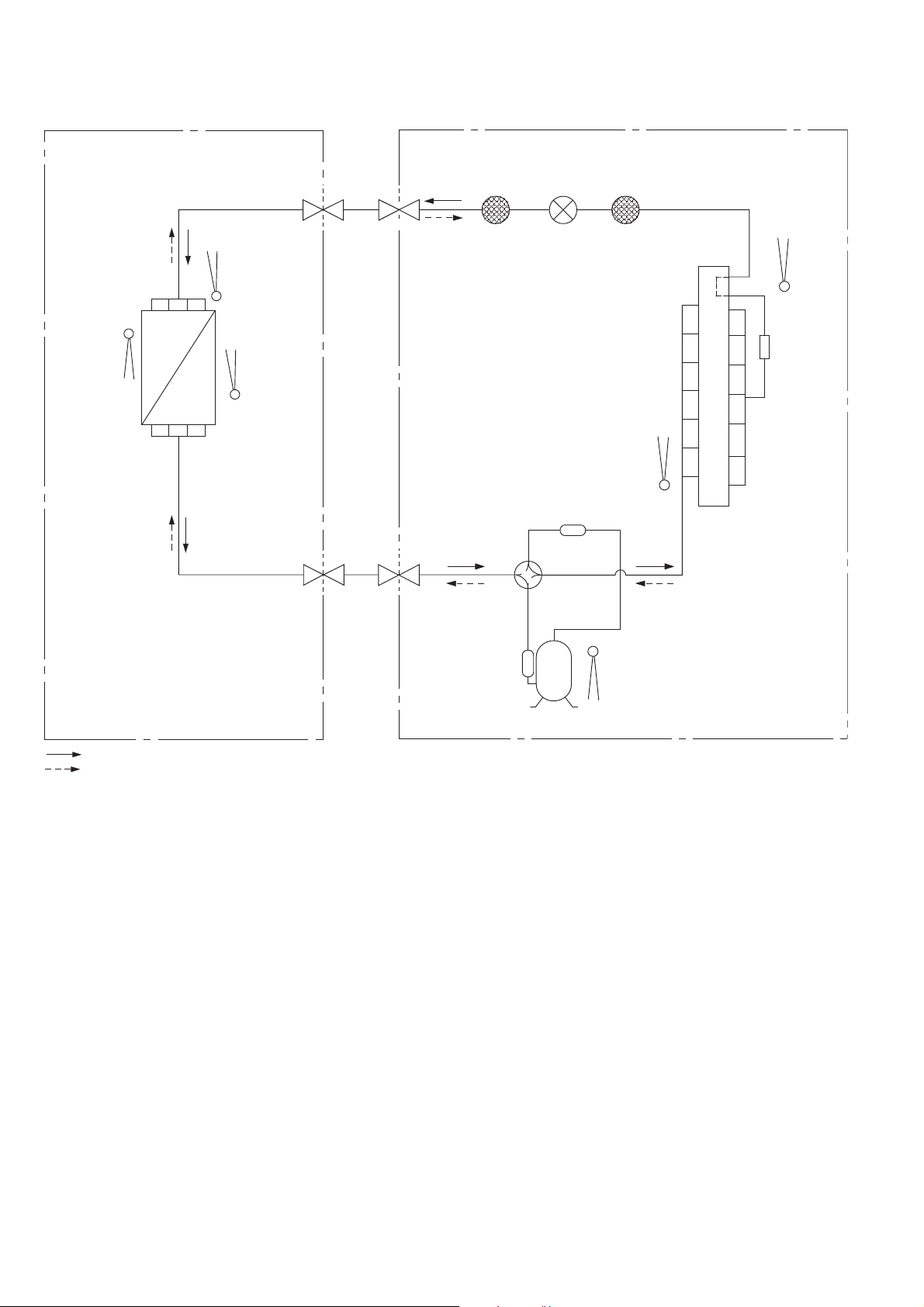
6.3 CS-E18SD3UAW CU-E18SD3UA
INDOOR
OUTDOOR
INTAKE
TEMP.
SENSOR
HEAT EXCHANGER
(EVAPORATOR)
PIPE
TEMP.
SENSOR 1
PIPE
(INLET)
TEMP.
SENSOR 2
LIQUID
SIDE
2-WAY
VALV E
GAS
SIDE
3-WAY
VALV E
4-WAYS VALVE
EXPANSION
VALV E
DISCHARGE
MUFFLER
STRAINERRECEIVER
PIPE
TEMP.
SENSOR
AIR
TEMP.
SENSOR
DISTRIBUTOR
COOLING
HEATING
COMPRESSOR
TEMP. SENSOR
COMPRESSOR
20
Page 21
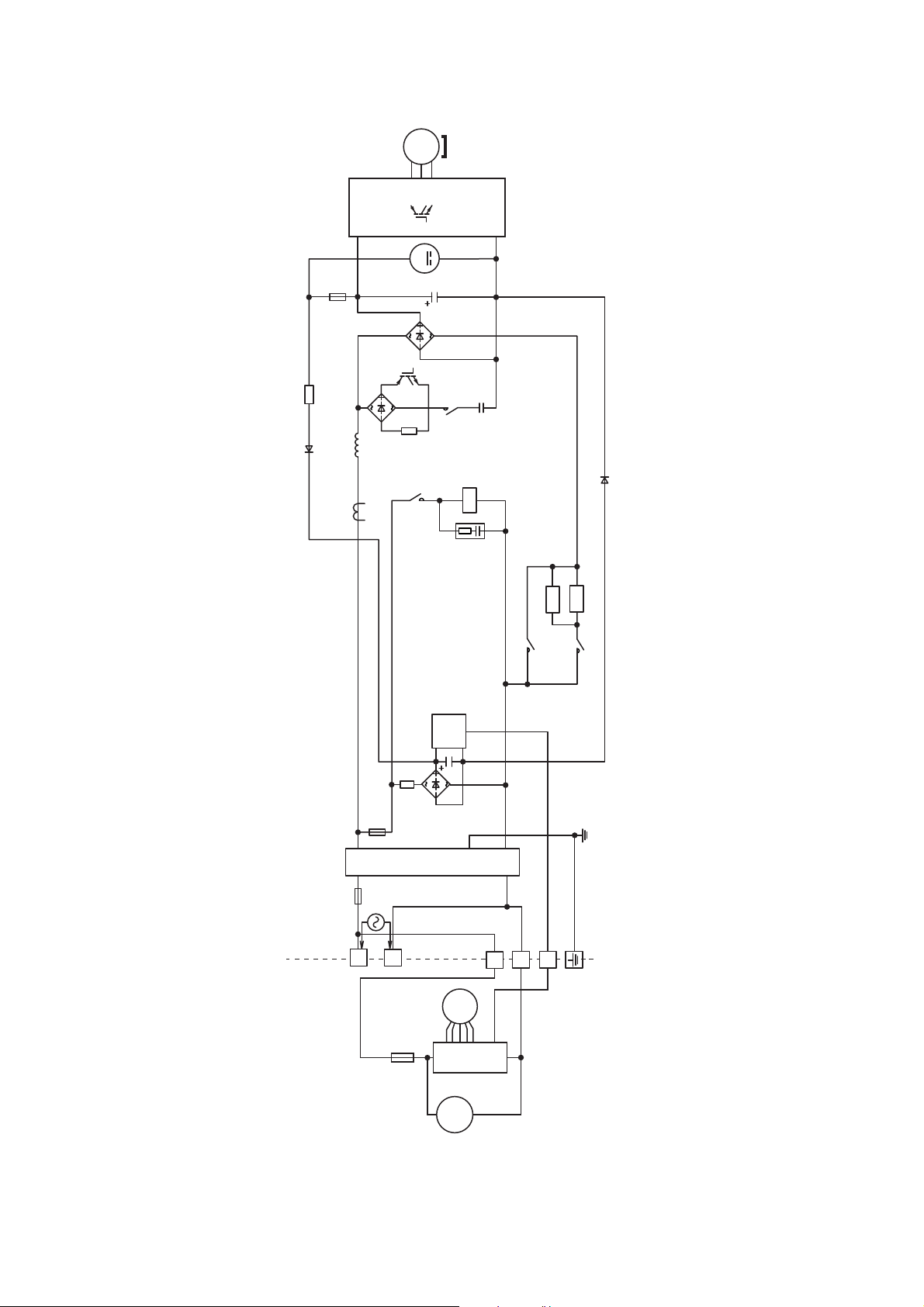
7. Block Diagram
7.1 CS-E9SD3UAW CU-E9SD3UA CS-E12SD3UAW CU-E12SD3UA
3 ~
MS
COMPRESSOR
Q1
PTC
PTC2
REACTOR
PTC
PTC1
DB101
DB102
NTC
TH2
M
EXPANSION
VALV E
DB103
FUSE103
FAN MOTOR
M
C101
RY-C
SC
U
4-WAYS
VALV E
RY-AC1
RY-PWR
FUSE102
FUSE101
1
Indoor Unit Outdoor Unit
SINGLE
PHASE
POWER
FUSE
SUPPLY
21
NOISE FILTER
60Hz
1 Ø 208/230V
FM
SC
DM
CT102
2
3
Page 22
7.2 CS-E18SD3UAW CU-E18SD3UA
3 ~
MS
U
V
W
COMPRESSOR
NTC
TH2
FUSE1
REACTOR
CT400
P
M
DB3
Q1
DB1
RY-HOT
N
RY-C
4-WAYS VALVE
CR3
PTC1
RY-PWR2
PTC2
RY-AC
FUSE2
FUSE3
SINGLE PHASE
POWER SUPPLY
AC208 - 230V
60Hz
L1
Indoor Unit Outdoor Unit
L2
TH1
NTC
FUSE
DB2
SC
NOISE FILTER
2
1
3
FM
SC
DM
22
Page 23
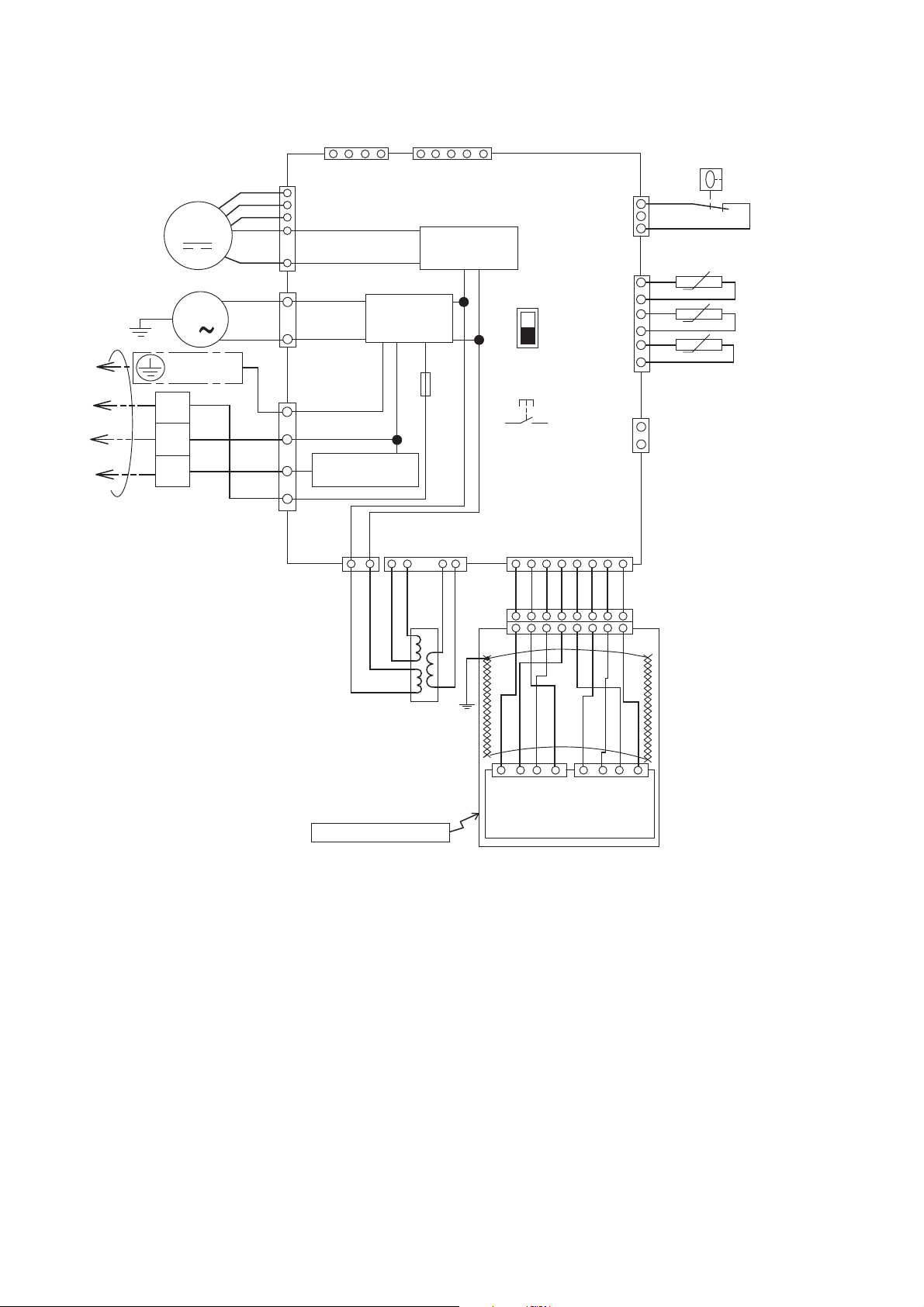
8. Wiring Connection Diagram
8.1 Indoor Unit
DRAIN PUMP
Y/G
GROUNDING
TERMINAL
1
2
TO OUTDOOR UNIT
3
TERMINAL
BOARD
MOTOR
M
M
1
BL
W
R
Y
B
W
BL
R
Y
Y
G
141
HAJEM-A
(WHITE)
7
CN-FM
6
(WHITE)
5
4
1
3
CN-DRMTR1
(BLUE)
1
1
CN-AC (WHITE)
3
5
COMMUNICATION
NOISE FILTER
CIRCUIT
CIRCUIT
7
CN-T1
(BLUE)
4
BL BL
CN-T2 (WHITE)
6
1 1 2 3 4
O O R R
CN-CNT
(WHITE)
RECTIFICATION
CIRCUIT
FUSE
T3.15A L250V
2
5
5
ELECTRONIC
CONTROLLER
SW2
SW1
DRAIN TEST
1
G
CN-DISP (WHITE)
BR R O Y P B V GR
1 2 3 4 5 6 7 8
BL
1 2 3 4
CN-FSW
(GREEN)
CN-TH
(WHITE)
CN-HT
(WHITE)
5 6 7 8
5 6 7 8
BL
1
3
BL
BL
6
BL
t˚
BL
BL
t˚
BL
BL
1
2
1
t˚
BL
FLOAT
SWITCH
INDOOR PIPE TEMPERATURE
SENSOR 2
INDOOR PIPE TEMPERATURE
SENSOR 1
INDOOR AIR TEMPERATURE
SENSOR
REMARKS
B: BLUE P:PINK
BR: BROWN O: ORANGE
BL: BLACK Y: YELLOW
W: WHITE GR: GRAY
R: RED G: GREEN
V: VIOLET Y/G: YELLOW/GREEN
TRANSFORMER
REMOTE CONTROLLER
BL
YBR GRRO VW
1 2 3 4 1 2 3 4
CN-DISP2
(WHITE)
CN-DISP1
(YELLOW)
DISPLAY & RECEIVER
23
Page 24
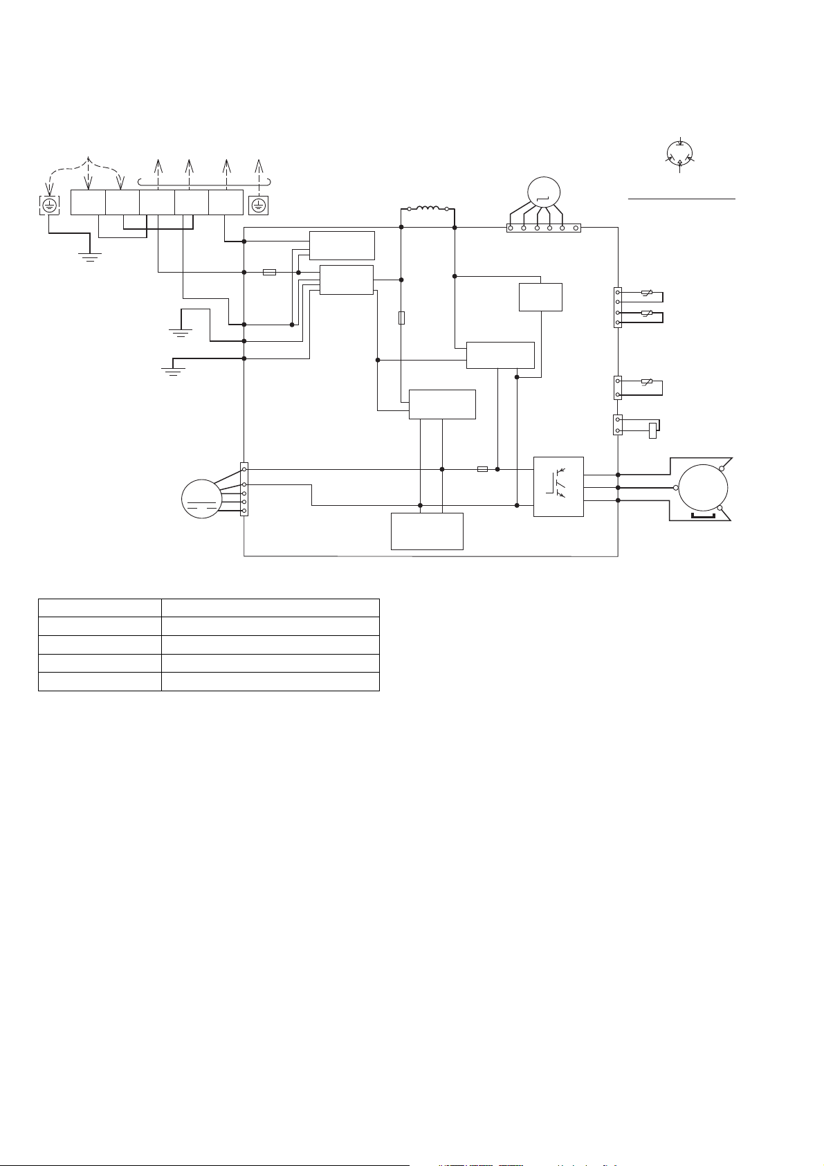
8.2 Outdoor Unit
8.2.1 CU-E9SD3UA CU-E12SD3UA
SINGLE PHASE
POWER SUPPLY
L2
L1
YLW/GRN
REMARKS
BLK: BLACK
BLU: BLUE
WHT: WHITE
RED : RED
YLW : YELLOW
GRY : GRAY
GRN: GREEN
BRW: BROWN
ORG: ORANGE
YLW/GRN: YELLOW/GREEN
BLK
TO INDOOR UNIT
1
(BLACK)2(WHITE)
BLK
WHT
GRN
MOTOR
WHT
GRN
FAN
M
3
(RED)
RED
TERMINAL BOARD
DATA (RED)
AC-BLK
(BLK)
FUSE101
20A 250V
AC-WHT
(WHT)
FG1 (GRN)
LJP101 (GRN)
1
4
CN-DCFM
(WHT)
7
COMMUNICATION
CIRCUIT
NOISE FILTER
CIRCUIT
REACTOR
GRY GRY
RAT2
(GRY)
FUSE102
RECTIFICATION
SWITCHING
POWER SUPPLY
CIRCUIT
RAT1
(GRY)
T3.15A L250V
CIRCUIT
T3.15A L250V
ELECTRO-MAGNETIC
COIL (EXPANSION VALVE)
M
1
RECTIFICATION
CIRCUIT
FUSE103
CN-STM
(WHT)
CIRCUIT
PFC
P
N
6
CN-TANK
(WHT)
CN-HOT
(WHT)
Q1
CN-TH
(WHT)
U
V
W
ELECTRONIC CONTROLLER
(RED)
(BLU)
(YLW)
1
2
3
4
1
3
1
2
Resistance of Compressor Windings
MODEL CU-E9SD3UA/CU-E12SD3UA
CONNECTION 5RS102XHA21
U-V 1.741 Ω
U-W 1.765 Ω
V-W 1.711 Ω
Note: Resistance at 68°F of ambient temperature.
YELLOW (YEL)
BLUE (BLU)
(TRADEMARK)
COMPRESSOR TERMINAL
THE PARENTHESIZED LETTERS IS
INDICATED ON TERMINAL COVER
AIR TEMP. SENSOR
(THERMISTOR)
t˚
t˚
PIPING TEMP. SENSOR
(THERMISTOR)
COMPRESSOR TEMP. SENSOR
(THERMISTOR)
t˚
YLW
YLW
RED
BLU
YLW
RED (RED)
ELECTRO-MAGNETIC
COIL (4-WAY VALVE)
MS
3~
COMPRESSOR
24
Page 25
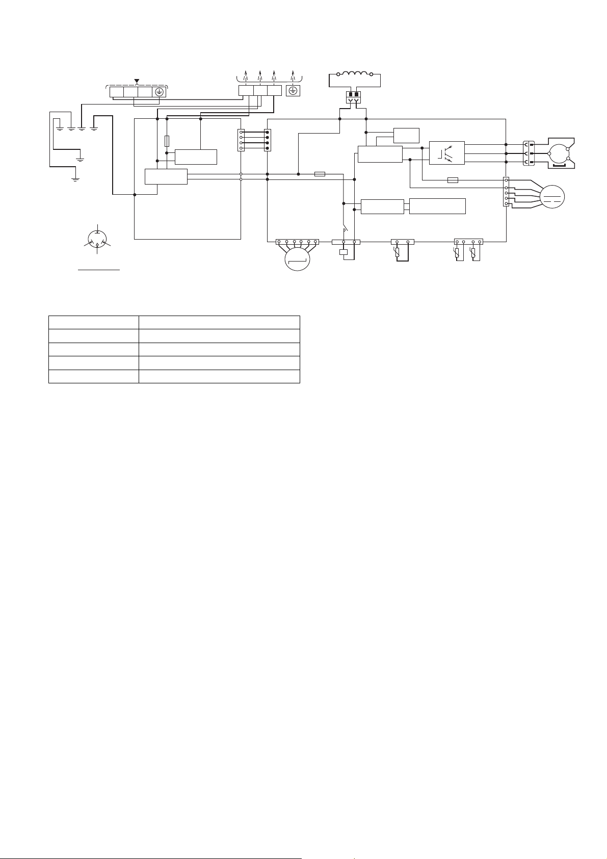
8.2.2 CU-E18SD3UA
SINGLE PHASE POWER SUPPLY
BLK
CIRCUIT
COM3
(RED)
TERMINAL
BOARD
CN-COM
(YELLOW)
CN-BLK
(BLACK)
CN-WHT
(WHITE)
GRN
L1 L2
RED
(RED)
YLW/GRN
GRN
YLW/GRN
YELLOW (YEL)
BLUE
(BLU)
(TRADEMARK)
COMP. TERMINAL
THE PARENTHESIZED LETTERS IS
INDICATED ON THE TERMINAL COVER
WHT
ACN1
(WHITE)
NOISE FILTER
CIRCUIT
FG1 (GREEN)
ELECTRONIC CONTROLLER
(NOISE FILTER)
TERMINAL
BOARD
WHT
BLK
ACL1
(BLACK)
FUSE3
(25A, 250V)
COMMUNICATION
Resistance of Compressor Windings
MODEL CU-E18SD3UA
CONNECTION 5KD240XAF21
U-V 0.720 Ω
U-W 0.726 Ω
V-W 0.708 Ω
Note: Resistance at 68°F of ambient temperature.
1
WHT
1
WHT
WHT
WHT
4
WHT
TO INDOOR UNIT
23
RED
1
CN-COM
(YELLOW)
4
AC-BLK
(BLACK)
BLK
AC-WHT
(WHITE)
6
ELECTRO-MAGNETIC COIL
(EXPANSION VALVE)
(T3.15A L250V)
CN-EV
(WHITE)
M
REACTOR
GRY
2
GRY
L2-1
(GRAY)
FUSE2
RY-HOT
1
1
ELECTRO-MAGNETIC
COIL (4-WAY VALVE)
1
12
BLK
L2-0
(BLACK)
RECTIFICATION
CIRCUIT
RECTIFICATION
CIRCUIT
CN-HOT
(BLUE)
BLK
PFC
CIRCUIT
CN-TANK
(WHITE)
33
t˚
COMP. TEMP.
SENSOR
(THERMISTOR)
ELECTRONIC CONTROLLER (MAIN)
Q10
P
N
FUSE1
(T3.15A L250V)
SWITCHING POWER
SUPPLY CIRCUIT
1
PIPING TEMP.
SENSOR
(THERMISTOR)
(RED)
U
(BLUE)
V
(YELLOW)
W
(WHITE)
CN-TH1
(WHITE)
41
t˚ t˚
OUTDOOR AIR
TEMP. SENSOR
(THERMISTOR)
REMARKS
BLU: BLUE BRW: BROWN
ORG: ORANGE BLK: BLACK
YLW: YELLOW WHT: WHITE
GRY: GRAY RED: RED
GRN: GREEN
YLW/GRN: YELLOW/GREEN
COMPRESSOR
3
RED
BLU
YLW
RED
BLK
WHT
BLU
YLW
11
3
RED
BLU
YLW
FAN MOTOR
CN-FM
U
V
W
1
4
7
MS
3
~
M
25
Page 26
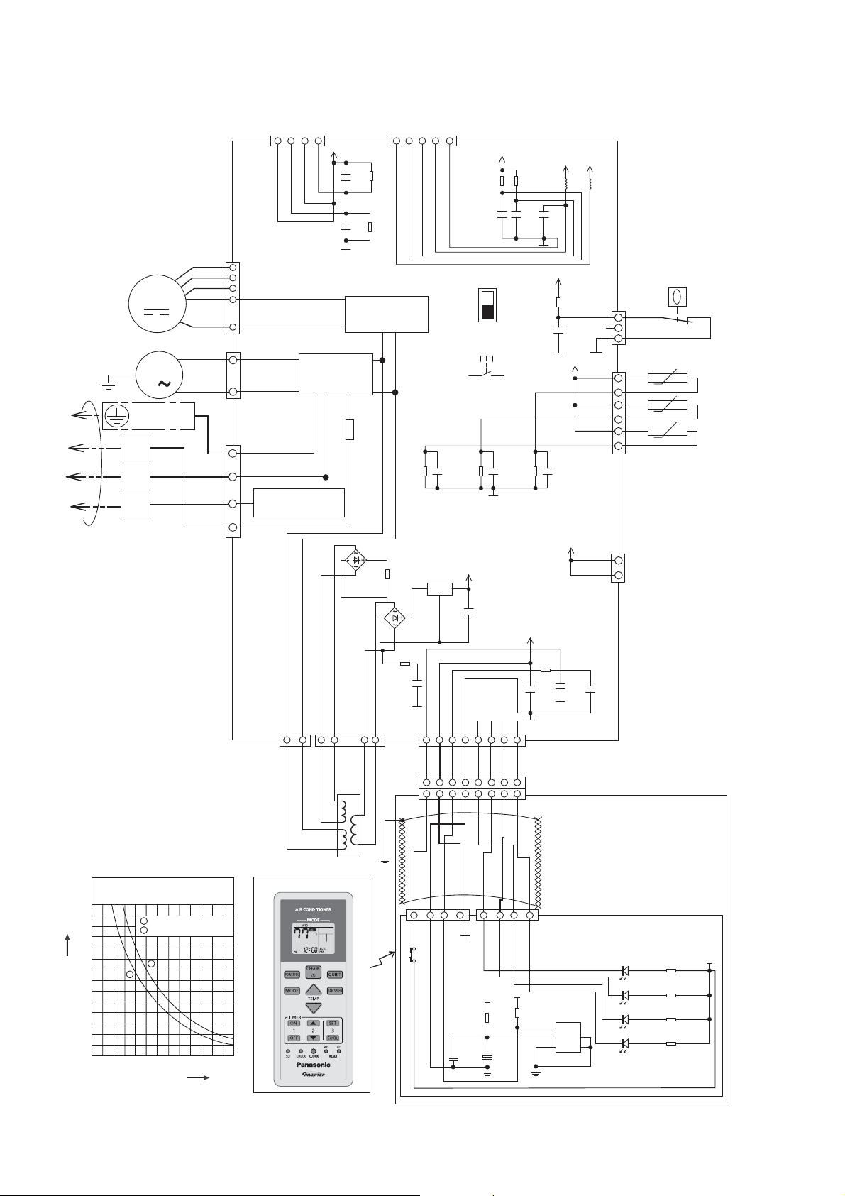
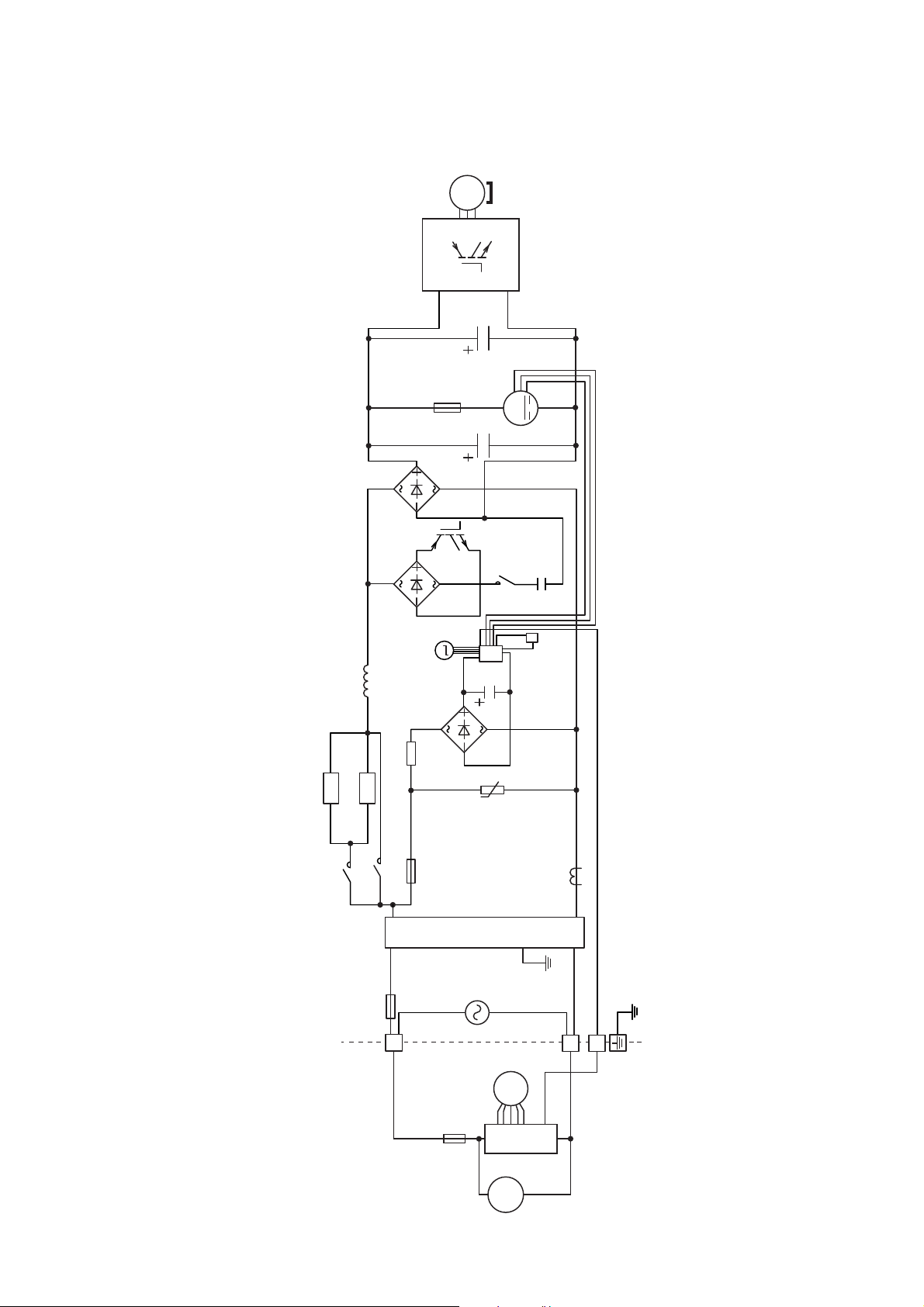
9. Electronic Circuit Diagram
9.1 Indoor Unit
5V
NOISE FILTER
CIRCUIT
FUSE
S1WB(A)60
6
1 1 2 3 4
5
O O R R
DRAIN PUMP
Y/G
GROUNDING
TERMINAL
1
2
TO OUTDOOR UNIT
3
TERMINAL
BOARD
MOTOR
M
M
1
BL
W
14
HAJEM-A
(WHITE)
Y
7
B
W
BL
R
Y
Y
R
G
CN-FM
6
(WHITE)
5
4
1
3
CN-DRMTR1
(BLUE)
1
1
CN-AC (WHITE)
3
5
COMMUNICATION
CIRCUIT
7
CN-T1
4
(BLUE)
BL BL
1
KB
R20
C32
10k
0.01u
KB
R56
C38
10k
0.01u
RECTIFICATION
CIRCUIT
T3.15A L250V
15.0k
R74
22k
DB3
1/4W
S1WB(A)60
R75
5.1k
KB
C46
0.1u
25V
CN-T2
(WHITE)
2
1
BL
G
CN-CNT
(WHITE)
1000p
R90
10k
KB
C52
50V
5V
5
SW2
SW1
DRAIN TEST
R62
1%
KB
C30
1u
10V
R63
20.0k
1%
KB
C31
1u
10V
ELECTRONIC
CONTROLLER
IC5
NJM7812FA
DB2
BR R O Y P B V GR
1 2 3 4 5 6 7 8
1 2 3 4
12V
i
o
12V
g
C8
NONE
CN-DISP
(WHITE)
5 6 7 8
5 6 7 8
R82
10k
C66
1000p
50V
R89
20.0k
1%
KB
12V
5V
L6
L5
C56
5V
CN-FSW
R65
(GREEN)
KB
C51
1u
10V
10k
1000p
KB
C35
50V
5V
CN-TH
(WHITE)
12V
1
3
CN-HT
(WHITE)
2
BL
FLOAT
SWITCH
BL
6
BL
BL
t˚
BL
BL
t˚
BL
BL
1
t˚
INDOOR PIPE
TEMPERATURE
SENSOR 2
INDOOR PIPE
TEMPERATURE
SENSOR 1
INDOOR AIR
TEMPERATURE
SENSOR
1
5V
R32
10k
KB
C17
0.01u
KB
C22
3300p
C34
0.1u
16V
KB
BL
70
60
50
40
30
Resistance (kΩ)
20
10
0
14 32 50
Sensor (Thermistor)
Characteristics
1
Pipe Temp. Sensor
2
Intake Air Temp. Sensor
1
2
68 86 104 122
o
Temperature (
F)
TRANSFORMER
REMOTE CONTROLLER
BL
YBR GRRO VW
1 2 3 4 1 2 3 4
SW201
5V
CN-DISP2
(WHITE)
C202
0.1uF
5V
R202
47
C201
+
47uF
6.3V
26
5V
R201
10k
CN-DISP1
(YELLOW)
IC201
GP1UM262RK
VOUT
1
VCC
235
GND
DISPLAY & RECEIVER
LED202
POWER GREEN
LED203
TIMER ORANGE
LED204
POWERFUL ORANGE
LED205
4
QUIET ORANGE
R2 0
R3 0
R4 0
R5 0
5V
Page 27
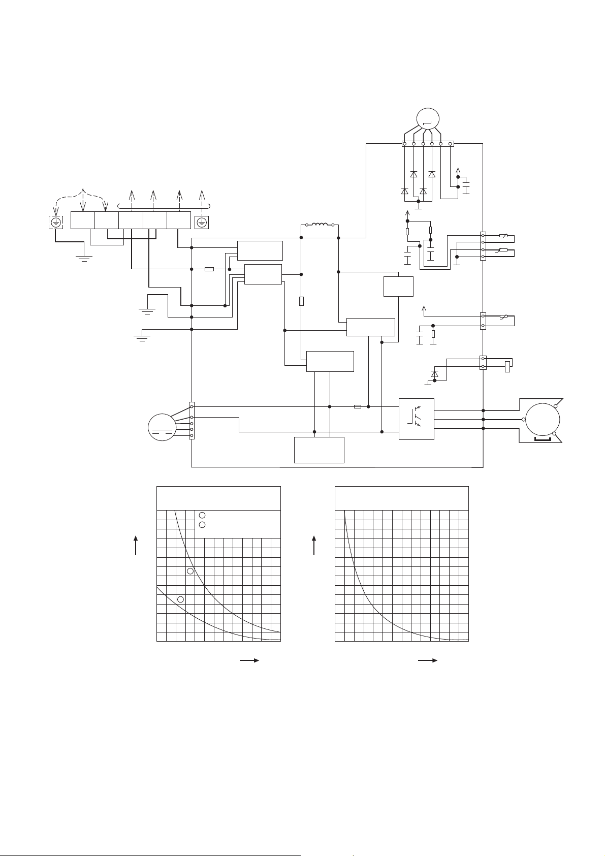
9.2 Outdoor Unit
9.2.1 CU-E9SD3UA CU-E12SD3UA
SINGLE PHASE
POWER SUPPLY
L1
YLW/GRN
L2
BLK
TO INDOOR UNIT
1
(BLACK)2(WHITE)
WHT
BLK
GRN
WHT
FAN
MOTOR
GRN
M
3
(RED)
RED
TERMINAL BOARD
DATA (RED)
AC-BLK
(BLK)
FUSE101
20A 250V
AC-WHT
(WHT)
FG1 (GRN)
LJP101 (GRN)
1
4
CN-DCFM
(WHT)
7
COMMUNICATION
CIRCUIT
NOISE FILTER
CIRCUIT
REACTOR
GRY
RAT2
(GRY)
FUSE102
RECTIFICATION
SWITCHING
POWER SUPPLY
CIRCUIT
GRY
RAT1
(GRY)
T3.15A L250V
RECTIFICATION
CIRCUIT
FUSE103
T3.15A L250V
ELECTRO-MAGNETIC
COIL (EXPANSION VALVE)
M
CN-STM
16
(WHT)
D28
D27
D29
5V
G2
R11
15.8k
1%
C6
1u
KB
CIRCUIT
10V
PFC
CIRCUIT
G2
G2
5V
C3
1u
KB
10V
G2
G2
D9
G2
Q1
P
U
V
W
N
ELECTRONIC CONTROLLER
D26
R12
15.0k
1%
C7
1u
KB
10V
4.99k
R1
1%
(RED)
(BLU)
(YLW)
13V
G2
CN-TH
(WHT)
G2
CN-TANK
(WHT)
CN-HOT
(WHT)
C80
AIR TEMP. SENSOR
(THERMISTOR)
t˚
1
2
t˚
3
4
PIPING TEMP. SENSOR
(THERMISTOR)
1
t˚
3
1
YLW
2
YLW
RED
BLU
YLW
COMPRESSOR
TEMP. SENSOR
(THERMISTOR)
ELECTRO-MAGNETIC
COIL (4-WAY VALVE)
MS
3~
COMPRESSOR
70
60
50
40
30
0
14 32 50
2
Resistance (kΩ)
20
10
Sensor (Thermistor)
Characteristics
1
Outdoor Air Sensor
2
Outdoor Heat Exchanger
Sensor
1
68 86 104 122
o
Temperature (
F)
Compressor Temp. Sensor
(Thermistor) Characteristics
70
60
50
40
30
Resistance (kΩ)
20
10
0
68 104 140
Temperature (
176 212 248 284
o
F)
27
Page 28
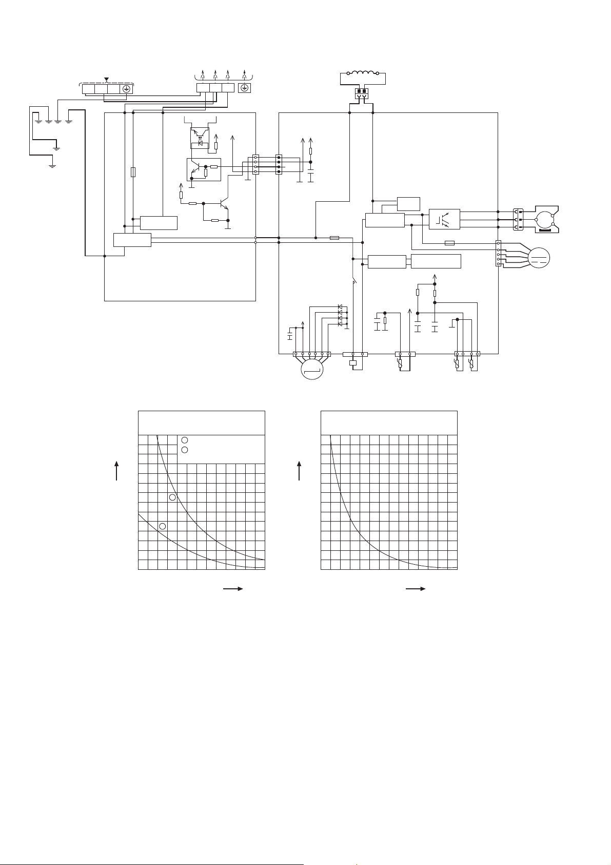
9.2.2 CU-E18SD3UA
SINGLE PHASE POWER SUPPLY
TERMINAL
BLK
WHT
COM3
(RED)
PC8
EL816X
(X)
Q25
0.1A
50V
RT1N432C
5V
R425
20.0k
1/10W
CIRCUIT
ELECTRONIC CONTROLLER
(NOISE FILTER)
BOARD
GRN
YLW/GRN
YLW/GRN
GRN
L1 L2
WHT
ACN1
(WHITE)
NOISE FILTER
FG1 (GREEN)
CIRCUIT
TERMINAL
BOARD
BLK
ACL1
(BLACK)
FUSE3
(25A, 250V)
COMMUNICATION
G1
R426
5.6k
1/10W
3
2
c
e
TO INDOOR UNIT
1
23
RED
4
5V
R422
680
1
1/10W
4.7k
b
10k
Q26
b
0.2A
50V
2SC3052
R427
47k
1/10W
5V
c
e
G1
CN-COM
(YELLOW)
G1
CN-BLK
(BLACK)
CN-WHT
(WHITE)
REACTOR
1
12
BLK
L2-0
(BLACK)
RECTIFICATION
CIRCUIT
RECTIFICATION
CIRCUIT
KB
C49
1u
6.3V
G5
G5
CN-HOT
(BLUE)
BLK
ELECTRONIC CONTROLLER (MAIN)
PFC
Q10
CIRCUIT
R410
4.99k
1/10W
1%
33
t˚
COMP. TEMP.
SENSOR
(THERMISTOR)
P
N
(T3.15A L250V)
SWITCHING POWER
SUPPLY CIRCUIT
5V
R101
15.8k
1/10W
1%
5V
KB
C46
1u
6.3V
G5
G5
CN-TANK
(WHITE)
1
FUSE1
R100
15.0k
1/10W
1%
KB
C45
1u
6.3V
PIPING TEMP.
(THERMISTOR)
(RED)
U
V
W
G5
41
t˚ t˚
SENSOR
U
V
(BLUE)
(YELLOW)
CN-FM
(WHITE)
CN-TH1
(WHITE)
OUTDOOR AIR
TEMP. SENSOR
(THERMISTOR)
COMPRESSOR
3
3
RED
RED
BLU
BLU
MS
3
YLW
FAN MOTOR
M
~
YLW
W
11
1
RED
4
BLK
WHT
BLU
7
YLW
GRY
2
GRY
L2-1
(GRAY)
5V
5V
CN-COM
(YELLOW)
1
WHT
WHT
WHT
WHT
4
AC-BLK
(BLACK)
BLK
WHT
AC-WHT
(WHITE)
C84
R159
1
4
10k
KB
C63
1000p
50V
G5
G6
(T3.15A L250V)
13V
G2
M
ELECTRO-MAGNETIC COIL
(EXPANSION VALVE)
FUSE2
RY-HOT
D33
D34
D35
D36
G2
CN-EV
(WHITE)
116
ELECTRO-MAGNETIC
COIL (4-WAY VALVE)
70
60
50
40
30
Resistance (kΩ)
20
2
10
0
14 32 50
Sensor (Thermistor)
Characteristics
1
Outdoor Air Sensor
2
Outdoor Heat Exchanger
Sensor
1
68 86 104 122
Temperature (
o
F)
70
60
50
40
30
Resistance (kΩ)
20
10
0
68 104 140
Compressor Temp. Sensor
(Thermistor) Characteristics
176 212 248 284
Temperature (
o
F)
28
Page 29
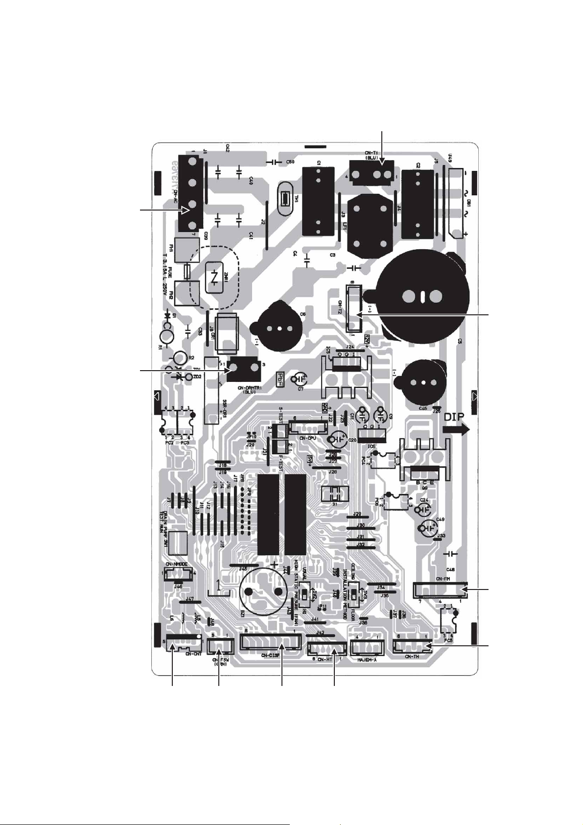
10. Printed Circuit Board
10.1 Indoor Unit
10.1.1 Main Printed Circuit Board
CN-AC
CN-T1
CN-T2
CN-DRMTR1
CN-FM
CN-TH
CN-DISP CN-HTCN-FSWCN-CNT
29
Page 30
10.2 Outdoor Unit
10.2.1 Main Printed Circuit Board
10.2.1.1 CU-E9SD3UA CU-E12SD3UA
POWER
TRANSISTOR
(IPM)
CURRENT
TRANSFORMER
(CT)
AC-WHT
AC-BLK
CN-HOT
CN-TH
CN-TANK
CN-DCFM
DATA
30
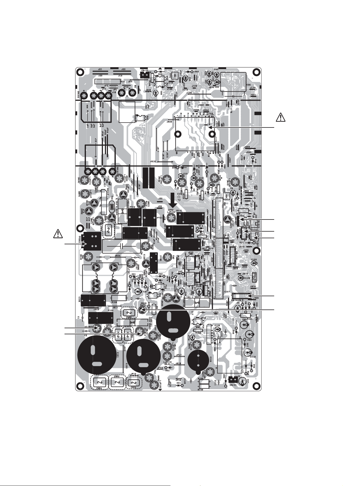
Page 31

10.2.1.2 CU-E18SD3UA
POWER
TRANSISTOR
(IPM)
AC-WHT
CURRENT
TRANSFORMER
(CT)
CN-COM
AC-BLK
CN-HOT
CN-FM
CN-TANK
CN-EV
CN-TH1
31
Page 32

10.2.2 CPU Printed Circuit Board
10.2.2.1 CU-E9SD3UA CU-E12SD3UA
CN1 CN2 CN3
10.2.3 Noise Filter Printed Circuit Board
10.2.3.1 CU-E18SD3UA
ACN1
(WHITE)
ACL1
(BLACK)
32
CN-COM
Page 33

11. Installation Instruction
IMPORTANT (ONLY FOR E9SD3UAW AND E12SD3UAW)
This product has been designed and manufactured to meet ENERGY STAR
matched with appropriate coil components. However, proper refrigerant charge and proper air flow are critical to
achive rated capacity and efficiency. Installation of this product should follow the manufacturer’s refrigerant
charging and air flow instructions. Failure to confirm proper charge and airflow may reduce energy
efficiency and shorten equipment life.
Attached Accessories
No. Accessory part Qty.
Remote control
1
Battery
2
Remote control holder
3
Remote control holder
4
fi xing screw
Remote control receiver
5
No. Accessory part Qty.
Receiver fi
xing screw
(M4 x 39/64" (15.5 mm))
6
1
Clamper (band)
(for receiver cable fi xing)
7
2
1
2
1
Receiver cable
(6.56 ft (2 m))
8
Washer
(for suspension fi tting)
9
Flare insulator
(for gas pipe / liquid pipe
0
connection)
■
Required Materials
Read the catalog and other technical materials and prepare the required materials.
Applicable piping kit
Applicable piping kit
CZ-3F5, 7BP 3/8" (9.52 mm) 1/4" (6.35 mm)
CZ-4F5, 7, 10BP 1/2" (12.7 mm) 1/4" (6.35 mm)
CZ-52F5, 7, 10BP 5/8" (15.88 mm) 1/4" (6.35 mm)
Piping size
Gas Liquid
Pipe size reducer (CZ-MA1P) for outdoor Multi connection CS-E12SD3UAW, CS-E18SD3UAW
®
criteria for energy efficiency when
No. Accessory part Qty.
Clamper (band)
2
1
1
8
2
(for fl are & drain insulating
!
connection)
Drain hose
(for unit & PVC pipe
@
connection)
Hose band
#
(for drain hose connection)
Drain hose insulation
$
(for drain pipe connection)
Clamper (band)
(for power supply cord)
%
* Be sure to fi x the power supply cord
with clamper (band).
Drain elbow
¥
L=131
4
1
1
2
1
1
33
Page 34

■
Other Items to be Prepared (Locally Purchased)
Product name Remarks
Rigid PVC pipe VP20 (outer diameter ø1 1/32" (ø26); also sockets, elbows and other parts as necessary
Adhesive PVC adhesive
Insulation
For refrigerant piping insulation: foamed polyethylene with a thickness of 5/16" (8 mm) or more.
For drain piping insulation: foamed polyethylene with a thickness of 13/32" (10 mm) or more.
Indoor/outdoor connecting cable UL listed or CSA approved 4 conductor wires minimum AWG16
Hanging bolt related parts Hanging bolts (M10) (4) and nuts (12), (when hanging the indoor unit)
Insulation of piping connections
• Carry out insulation after
checking for gas leaks and
secure with vinyl tape.
Vinyl tape
Indoor unit
A
B
Outdoor
unit
IMPORTANT
Begin the installation job from
the “Indoor Unit” installation.
Model
E9SD3UAW 9000
E12SD3UAW 11500
E18SD3UAW 17200
Capa-
city
(Btu/h)
Piping size
Gas Liquid
3/8"
(9.52
mm)
1/2"
1/4"
(12.7
(6.35
mm)
mm)
1/2"
(12.7
mm)
Attaching the remote control holder to the wall
Remote control holder fi xing screws
Remote
1
control
Remote control holder
Max
Min.
Std.
Length
24.6 ft
(7.5 m)
Eleva-
tion
49.2 ft
(15 m)
Length
Piping
9.8 ft
(3 m)
Max.
Piping
Length
65.6 ft
(20 m)
100.0 ft
(30.5 m)
4
Additional
Refri-
gerant
0.2
oz/ft
(20
g/m)
0.3
oz/ft
(25
g/m)
Installation parts you
should purchase (
Sleeve (
3
Piping
Length
for add.
gas
24.6 ft
(7.5 m)
32.8 ft
(10 m)
Example: For E9SD3UAW
If the unit is installed at 32.8 ft (10 m) distance, the
quantity of additional refrigerant should be 1.64 oz
(50 g) …. (32.8 - 24.6) ft x 0.2 oz/ft = 1.64 oz.
((10 - 7.5) m x 20 g/m = 50 g).
15
3
/16"
(100 mm)
or more
3
/8"
39
(1000 mm)
or more
/16"
15
3
(100 mm)
or more
11
13
(300 mm)
/16"
or more
)
)
Bushing-Sleeve (
Putty
(Gum Type Sealer) (
Bend the pipe as
closely on the wall
as possible, but
be careful that it
doesn’t break.
Vinyl tape (Wide) (
• Apply after carrying
out a drainage test.
• To carry out the
drainage test,
remove the air
fi lters and pour
water into the heat
exchanger.
Saddle (
Power supply
cable (
)
Connection cable (
1/4" (6.35 mm)
Liquid side piping
)
(
Gas side piping (
Additional
drain hose (
)
)
)
)
)
)
)
It is advisable to avoid more than 2 blockage
directions. For better ventilation & multiple-outdoor
installation, please consult authorized dealer/specialist.
Or
This illustration is for explanation purposes only.
The indoor unit will actually face a different way.
34
Page 35

11.1 Indoor Unit
11.1.1 Selecting the Installation Location
Take into consideration the following contents when creating the blueprint.
■
Indoor unit installation location
Do not install the unit in excessive oil fume area such as kitchen, workshop and etc.
The location should be strong enough to support the main unit without vibration.
There should not be any heat or steam source nearby.
Drainage should be easy. Avoid locating the drain port close to ditches (domestic wastewater).
Avoid locations above entrances and exits.
Do not block the air intake and discharge passages.
Select the location that enables the cool and warm air to spread out to the entire room.
Locate the indoor unit at least 3.28 ft (1 m) or more away from a TV, radio, wireless appliance, antenna cable and
fluorescent light, and 6.56 ft (2 m) or more away from a telephone.
Recommended installation height for indoor unit shall be at least 8.27 ft (2.5 m) from floor.
11.1.2 To Drill a Hole in the Wall and Install a Sleeve of Piping
1 Insert the piping sleeve to the hole.
2 Fix the bushing to the sleeve.
3 Cut the sleeve until it extrudes about 19/32"
(15 mm) from the wall.
When the wall is hollow, be sure to use the sleeve for tube
assembly to prevent pests from damaging the cables, e.g.
mice biting the connection cable.
4 Finish by sealing the sleeve with putty or
caulking compound at the final stage.
Indoor
Sleeve
for tube
assembly
3
ø
/4
2
"
(ø70 mm)
through hole
Wall
Outdoor
Bushing for
19
/32"
(15 mm)
Putty or caulking compound
tube assembly
Approx.
7
/32
" -
(5 - 7 mm)
9
"
/32
11.1.3 Installing the Indoor Unit (Installation Embedded in the Ceiling)
11.1.3.1 Preparation Before Installation
Always provide sufficient entry and exit space to allow installation work, inspection and unit replacement.
Waterproof the rear surface of the ceiling below the unit in consideration of water droplets forming and dropping.
When cooling operation is performed for an extended period under the following conditions, water droplets may form and drop. Attach locally
purchased insulation (foamed polyethylene with a thickness of 7/32" (5 mm) or more) to the outside of the indoor unit before installing into the
ceiling to improve heat insulation.
Locations with a dew point inside the ceiling of 73.4°F (23°C) or more
Kitchens and other locations that produce large amounts of heat and steam
Locations where the inside of the ceiling serves as an outside air intake passage
When installing into a ceiling, select the unit position and airflow direction that enable the cool and warm
air to spread out to the whole room.
Do not place objects that might obstruct the airflow within 3.28 ft (1 m) below the intake grill.
35
Page 36

Required Minimum Space for Installation and Service
7
/16" (
824) (Suspension bolt pitch)
32
7
Min. 7
/8"
564)
200) or
(
more
Min 3 15/
(
"
/32
7
22
Flange for air outlet duct
" (100 mm) or more for bottom
16
air intake
"
/8
7
or
200)
Min.
more
(
7
25
Min.
/32" (20) or more
Min. 25/32" (20) or more
Electrical
component box
Inspection
access
23
/32
17
23
/32
17
(
450 x 450)
Refrigerant tubing
19
Min. 25
/32
(
650) or more
" (200)
/8
7
7
Ceiling
x
"
"
"
" (240)
/16
*H=Min.
7
9
H dimension means the minimum height of the unit installation space.
Select H dimension such that a downward slope of at least 1/100 is ensured. Refer to 11.1.4 “Connecting the
drain piping”
Dimension of the Indoor Unit
" (145)
/32
23
5
27
(640)
"
/16
3
25
194)
" (564) (Suspension bolt pitch)
" (
/32
/8
7
5
7
22
(38)
"
/2
1
1
(126)
"
/32
31
4
1
/4
"
(692) (Flange for air outlet duct)
3
/16
" (640) (6
25
7
/16
32
" (824) (Suspension bolt pitch)
5-ø
29
26
5
1
"
/8
(ø3.1)(Hole)
17
/32
25
/32
"
/16
" (160) x 4)
" (750)
(680)
5
/32
" (29)
1
25
/32
3
5
2
" (66)
/8
1
/32
1
1 15/32
5 29/32"
(150)
" (96)
"
(26)
1
/16"
1
17
Suspension lug
"
(37)
"
/32
3
6
(27)
Inspection access
23
/32" X
17
23/32"
(40)
"
/16
1
"
/32
4
"
/32
19
(120)
/32
(14)
"
/16
9
(15)
"
(23)
9
/16
5
(132)
(450x450)
(Field supply)
(22)
"
9
/8
7
23
(155)
(23)
"
/32
29
29
3
" (28)
/32
1
3
/16
" (30)
1
3
/16
" (81)
3
5
1
(33)
1
6
(153)
"
(14)
3
/16
"
5
3
"
/16
(84)
Water inlet
"
/16
/32
"
29
/32
5
" (150)
7
" (200)
/8
7
1
/8
"
10-ø
(ø3.1)(Hole)
8
(220)
21
27
/32
23
"
/32
21
8
(220)
" (704)
* Filter Uninstalled
2-ø
/32
13
"
/32
1
"
/8
(ø3.1)
(Hole)
(10)
"
/8
5
5
"
/32
5
3
"
"
/16
3
1
(143)
(80)
" (44)
/32
23
1
3
5
(132)
(30)
" (238)
/8
3
9
"
/16
29
/32
"
(23)
9
/16
" (14)
36
Page 37

In Case of Bottom Intake
1 Remove the frame filter assy as shown in
diagram 1
1
Air intake
Cover plate
2
Dummy hole
2 Remove cover plate as shown in diagram 1
3 Fix frame filter assy as shown in diagram 2
4 Fix cover plate as shown in diagram 2 with
the dummy hole downward.
Air
discharge
Dummy hole
Frame Filter
Assy
Cover plate
Air discharge
Air intake
Frame
Filter
Assy
Fixing Frame Filter Assy
Main unit
Filter Assy
In case of bottom side
* Attach the frame fi lter assy to
the main unit while pushing the
In case of back side
tip of the latches in the direction
of the arrow.
Ceiling Opening
Install inspection opening 17 23/32" x 17 23/32" (450 mm x 450 mm) on the control box side where maintenance
and inspection of the control box and drain pump are easy. Install another inspection opening 31 1/2" x 27 9/16"
(800 mm x 700 mm) also at the lower part of the unit.
27
9
/16
" (700)
700
Air
discharge
Inspection access
Air intake
A
Ceiling
Allow view A
(Field supply)
" (800)
800
/2
1
31
Securing the Hanging Bolts
Reinforced concrete
Hanging
bolt M10
/2" (114)
1
Approx.
4
Insert hole-in
anchor, etc.
”
Ceiling surface
Wooden of other structure
9
/16
" (40)
1
3
t =
" (2)
/32
3
/16
1
" (30)
(Hanging bolt pitch)
Hanging bolt
C channel
Hanging fi
xture
Hanging
bolt M10
(2
Reinforcing materials
3
17
/8
3
/32
" to
" (144)
/2
1
Approx.
4
") (60 to 90 mm)
Roof beam
Ceiling surface
Secure the hanging bolts (M10, locally purchased) firmly in a manner capable of supporting the unit weight.
Consult your construction or interior contractor for details on finishing the ceiling opening.
37
Page 38

Installing an Intake and Discharge Duct Type
Ensure the range of unit external static pressure is not exceeded. Refer technical manual for the range of
external static pressure setting.
Connect the duct as shown.
When attaching duct to the intake side, remove the product filter frame assy and replace with locally purchase
intake-side flange by using flange by using 10 - Ø 1/8" (Ø 3.1)(hole) screws.
Wrap the flange and duct connection area with aluminium tape or similar to prevent air leak.
Flange
(locally purchase)
Connection screw (x10)
Rectangular solic duct
Main unit
Flange
Insulation material
(locally purchased)
Air outlet sideAir inlet side
When attaching a duct to the intake-side, be sure to attach
an air filter inside the air passage on the intake-side.
(Use an air filter with dust collecting efficiency at least 50%
in a gravimetric technique.)
Installation into the Ceiling
Attach the nuts and washers to the hanging bolts, then lift up and hook the main unit onto the hanging fixtures.
Check if the unit is leveled using a level or a vinyl hose filled partially with water.
Hanging bolt (M10)
(locally purchased)
Washer
9
Level
Hexagonal nut (M10)
(locally purchased)
38
Page 39

Mounting Remote Controller Receiver
Install the remote controller receiver cable at least 1 31/32" (50 mm) away from electric wires of other appliances to avoid miss-operation
(electromagnetic noise).
1 Remove the bottom case.
Insert the driver
and slightly turn.
Bottom
case
Flat-blade
screwdriver
Attention
Mounting the bottom case
Screws
6
Tighten the screws securely until the screw heads
touch the bottom case. (Otherwise, loose screw
heads may hit the PCB and cause malfunction
when mounting the top case.)
Do not over-tighten the screws. (The bottom case
may be deformed, resulting in fall of the unit.)
Connecting the remote control wiring
Arrange the wires as shown in the illustration for 2 as in diagram below, avoiding unnecessary wires being
stored in the case. (Caught wires may destroy the PCB.)
Avoid wires touching parts on the PCB. (Caught wires may destroy the PCB.)
2 Mount to the wall.
EXPOSED TYPE
Preparation: Make 2 holes for screws using a driver.
Mount the top case.
• Align the claws of the
top case and then align
the claws of the bottom
case.
Cut here with
a nipper and
remove the burr
le.
with a fi
Claw (2 places)
Claw
Wood screw (supplied)
Connect the remote control wiring.
• Arrange the wires along the groove of the case.
Mount the bottom case
to the wall.
Wall to fi x the
receiver
Hole for screw
Preparation: Make 2 holes for screws using a driver.
Mount the top case.
• Align the claws of the
top case and then
align the claws of the
bottom case.
Avoid the wire
being caught.
Claw (2 places)
EMBEDDED TYPE
Mount the bottom case to the wall.
• Pass the wire through the hole in
the centre of the bottom case.
Claw
Hole for screw
Wood screw (supplied)
Connect the remote control wiring.
Top case
(Back side)
Bottom case (Back side)
Clamper 7
(supplied)
Pass
through
the hole
Terminal board
Top case
(Back side)
Bottom case (Back side)
39
Page 40

Connect the indoor unit and the remote control receiver 5. (Refer to the illustration.)
Fix the green wire from receiver cable 8 to the grounding location provided inside control board.
Control box
Receiver cable
Remote control
receiver
8
5
11.1.4 Connecting the Drain Piping
Lay the drain piping so as to ensure drainage.
Use a locally purchased VP20 general rigid PVC pipe (outer diameter ø1 1/32" (ø26)) for the drain piping and
firmly connect the indoor unit and the drain piping using supplied hose band to ensure that no leakage
occurs.
Drain piping located indoor should always be insulated by wrapping with locally purchased insulation (foamed
polyethylene with a thickness of 13/32" (10 mm) or more).
The drain piping should have a downward gradient (1/100 or more) and should be secured by using pipe hanging
equipment to avoid creating hills or traps partway.
Should there be any obstacle preventing the drain piping from being extended smoothly, the drain piping can be
raised outside of the main unit as shown in the illustration below.
Rise
At least 1/100
Good
Hill
13
" (300 mm) or less
/16
11
(not a downward gradient)
11
/16
" (500 mm) or less
19
Tr ap
Unit drain port
Do not use adhesive.
Drain hose insulation
Hose band
Drain hose
#
Hard PVC pipe (VP20)
@
Adhere with
PVC adhesive.
$
1
1
/32" (26)
1
"
/32
(26)
1
1
5
"
/8
(130)
Strictly do not install and extend the drain piping from the main unit drain water outlet horizontally or upward or raised it 19 11/16" (500 mm)
or more.
Doing so may result in poor drainage or drain motor failure.
Do not use drain hose bent at 90° angle. (The maximum permissible bend is 45°.)
11.1.5 Insulating the Refrigerant Piping
After the piping is connected, insulate. (Refer to the illustration)
Clamper
Wrap fi rmly
with vinyl tape,
leaving no gaps.
Unit side
Flare insulator
!
Wrap fi rmly
with vinyl tape,
leaving no gaps.
0
40
Page 41

11.1.6 Connect the Cable to the Indoor Unit
Remove control box cover.
Remove the plugs.
Fix the conduit connections to the knockout holes
together with lock nuts, then secure them against
the control box side panel.
Receiver cable wires 8 must pass through the
upper conduit hole.
Make sure the receiver cable is inserted from
inside of the control box.
Connect receiver cable connector to control box
wire connector and fix it to the power supply cord
holder as shown in the diagram.
Insert firmly the connector of receiver cable 8 to
connector at control box of indoor unit.
Connection cable between indoor unit and
outdoor unit should be UL listed or CSA approved
4 conductor wires minimum AWG16 in
accordance with local electric codes.
o Ensure that the terminal numbers on the
indoor unit are connected to the same
terminal numbers on the outdoor unit by the
right coloured wires as shown in the diagram.
o Earth lead wire should be longer than the
other lead wires as shown in the diagram for
electrical safety purpose in case the cord slips
out from the anchorage.
o Secure the cable onto the control board with
the holder (clamper).
Terminals on the indoor unit 1 2 3
Colour of wires
Terminals on the outdoor unit 1 2 3
When the wall is hollow, please be sure to use the sleeve
for tube ass’y to prevent dangers caused by mice biting the
connection cable.
Lock Nuts
Control Box
Control Box cover
Knockout holes
Screws
Plugs
Connectors
Fix the receiver cable to the holderFix receiver cable connector
Earth wire
(connection cable)
Indoor/outdoor connection terminal
Holder for
connection cable
Earth wire
(receiver cable)
Indoor/outdoor
connection cable
WARNING
This equipment must be properly earthed.
Ensure the colour of wires of outdoor unit and the
terminal Nos. are the same to the indoor’s
respectively.
Earth wire shall be Yellow/Green (Y/G) in colour
and longer than other AC wires for safety reason.
41
Page 42

11.1.6.1 Wire Stripping and Connecting Requirement
Wire stripping
Indoor/outdoor
connection
terminal board
7
10 ± 1 mm
13/32" ± 1/32"
No loose strand when inserted
Do not joint wires
/32" (5 mm)
or more
(gap between wires)
Conductor
fully inserted
ACCEPT
Conductor
over inserted
PROHIBITED
Conductor not
fully inserted
PROHIBITED
WARNING
RISK OF FIRE
JOINING OF WIRES MAY CAUSE
OVERHEATING AND FIRE.
Use complete wire without joining.
Use approved socket and plug with earth pin.
Wire connection in this area must follow to national wiring rules.
OR
OR
OR
42
Page 43

11.2 Outdoor Unit
11.2.1 Select the Best Location
11.2.2 Install the Outdoor Unit
After selecting the best location, start installation to Indoor/Outdoor Unit Installation Diagram.
1 Fix the unit on concrete or rigid frame firmly and horizontally with a bolt nut (ø 13/32" (ø10 mm)).
2 When installing at roof, please consider strong wind and earthquake.
Please fasten the installation stand firmly with bolt or nails.
AB
C
D
Model A B C D
E9SD3UAW,
E12SD3UAW
E18SD3UAW
22 7/16"
(570 mm)
24 1/8"
(613 mm)
4 1/8"
(105 mm)
5 5/32"
(131 mm)
23/32"
(18.5 mm)
5/8"
(16 mm)
12 19/32"
(320 mm)
14 3/16"
(360.5 mm)
11.2.3 Connect the Piping
11.2.3.1 Connecting the Piping to
Indoor
Please make flare after inserting flare nut (locate at
joint portion of tube assembly) onto the copper pipe.
(In case of using long piping)
Connect the piping
Align the center of piping and sufficiently tighten
the flare nut with fingers.
Further tighten the flare nut with torque wrench in
specified torque as stated in the table.
11.2.3.2 Connecting the Piping to
Outdoor
Decide piping length and then cut by using pipe cutter.
Remove burrs from cut edge.
Make flare after inserting the flare nut (locate at valve)
onto the copper pipe.
Align center of piping to valve and then tighten with
torque wrench to the specified torque as stated in the
table.
11.2.3.3 Connecting the Piping to
Outdoor Multi
Decide piping length and then cut by using pipe cutter.
Remove burrs from cut edge.
Make flare after inserting the flare nut (locate at valve)
onto the copper pipe.
Align center of piping to valve and then tighten with
torque wrench to the specified torque as stated in the
table.
Do not over tighten, overtightening may cause gas leakage.
Piping size Torque
1/4" (6.35 mm) 13.3 Ibf•ft [18 N•m (1.8 kgf•m)]
3/8" (9.52 mm) 31.0 Ibf•ft [42 N•m (4.3 kgf•m)]
1/2" (12.7 mm) 40.6 Ibf•ft [55 N•m (5.6 kgf•m)]
5/8" (15.88 mm) 47.9 Ibf•ft [65 N•m (6.6 kgf•m)]
3/4" (19.05 mm) 73.8 Ibf•ft [100 N•m (10.2 kgf•m)]
Spanner
or Wrench
To rq u e
wrench
Male side
(Auxiliary pipe)
Wrench
(Adjustable Wrench)
Male side
(Auxiliary pipe)
Wrench
(Adjustable Wrench)
Torque Wrench for Flare
Nut and Pipe Size Reducer
Hall Union
Hall Union
Flare Nut
Packing
(Connection pipe)
Torque Wrench
for Flare Nut
Pipe Size
Reducer
Female side
Applicable to
Liquid and Gas side of
CS-E9SD3UAW
Liquid side of
CS-E12SD3UAW
CS-E18SD3UAW
Flare Nut
(Connection pipe)
Applicable to
Gas side of
CS-E12SD3UAW
CS-E18SD3UAW
Female side
11.2.3.4 Gas Leak Checking
Pressure test to system to 400 PSIG with dry nitrogen, in stages. Thoroughly leak check the system. If the pressure
holds, release the nitrogen and proceed to section 4.
43
Page 44

11.2.4 Evacuation of the Equipment
WHEN INSTALLING AN AIR CONDITIONER, BE SURE TO EVACUATE THE AIR INSIDE THE INDOOR UNIT AND
PIPES in the following procedure.
Indoor unit
Vacuum
pump
1 Connect a charging hose with a push pin to the Low side of a charging set and the service port of the 3-way
valve.
2 Connect the micron gauge between vacuum pump and service port of outdoor units.
3 Turn on the power switch of the vacuum pump and make sure that connect digital micron gauge and to pull
down to a value of 500 microns.
4 To make sure micron gauge a value 500 microns and close the low side valve of the charging set and turn off
the vacuum pump.
5 Disconnect the vacuum pump house from the service port of the 3-way valve.
6 Tighten the service port caps of the 3-way valve at a torque of 13.3 Ibf•ft (18 N•m) with a torque wrench.
7 Remove the valve caps of both of the 2-way valve and 3-way valve. Position both of the valves to “Open”
using a hexagonal wrench (5/32" (4 mm)).
8 Mount valve caps onto the 2-way valve and the 3-way valve.
o Be sure to check for gas leakage.
If micron gauge value does not descend 500 microns, take the following measures:
- If the leak stops when the piping connections are tightened further, continue working from step 3.
- If the leak does not stop when the connections are retightened, repair location of leak.
- Do not release refrigerant during piping work for installation and reinstallation.
- Be careful with the liquid refrigerant, it may cause frostbite.
Liquid side
Gas side
Two-way valve
Close
Three-way valve
Close
Outdoor unit
44
Page 45

11.2.5 Connect the cable to the Outdoor Unit
For model E9SD3UAW, E12SD3UAW
1 Remove Top panel.
2 Remove Control Board Cover (Resin and
Metal).
3 Remove Plugs.
4 Fix the conduit connectors to the knockout
holes with lock-nuts, then secure them against
Control Board
Cover (Resin)
Control Board
Metal Cover
the side panel.
5 All wires pass through conduits.
6 Connection cable between indoor unit and
outdoor unit should be UL listed or CSA
approved 4 conductor wires minimum AWG16
in accordance with local electric codes.
7 Wire connection to the power supply
(208/230V 60Hz) through circuit breaker.
Connectors
o Connect the UL listed or CSA approved
wires minimum AWG14 to the terminal
board, and connect the other end of the
wires to ELCB / GFCI.
8 Connect the power supply cord and connection cable between indoor unit and outdoor unit according to the
diagram below.
Indoor Unit
1
2
3
208/230V min AWG16
208/230V min AWG16
208/230V min AWG16
Grounding wire min AWG16
* Ensure all connecting wire
between indoor unit and
outdoor unit and power supply
cord are installed in individual
conduit.
Outdoor Unit
re
TlanimreT
lanim
1
2
3
L1
L2
Disconnect
Switch
Field supply
Grounding wire
To p P a ne l
Lock Nuts
Knockout
Holes
Plugs
Side Panel
Power Supply
Single Phase
208/230V 60Hz
min AWG14
Powe r
Supply
Wires
9 Secure the wire onto the control board with the holder (clamper).
10 After completing wiring connections, reattach the control board cover (Metal and Resin) and the top panel to
the original position with the screws.
11 For wire stripping and connection requirement, refer to instruction 11.1.6 of indoor unit.
Terminal
Board
Earth
wire
longer
than
other AC
wires for
safety
reasons
Powe r
supply cord
Indoor & outdoor
connection cable
Earth
wire
longer
than
other AC
wires for
safety
reasons
Holder
WARNING
This equipment must be properly earthed.
Earth lead wire shall be Yellow/Green (Y/G) in colour and should be longer than other lead wires as shown in the
figure for electrical safety in case of slipping.
45
Page 46

For model E18SD3UAW
1 Remove control board cover (Resin and
Metal).
Front Panel
Connecting Wires
Control Board
Cover (Metal)
Control Board
Cover (Resin)
2 Remove particular plate.
3 Remove plugs.
4 Fix the conduit connectors to the knockout
holes with lock-nuts, then secure them against
Particular
Plate
Lock Nuts
the side panel.
5 All wires pass through conduits & particular
plate’s opening hole.
6 Connecting wire between indoor unit and
outdoor unit should be UL listed or CSA
approved 4 conductor wires minimum AWG16
in accordance with local electric codes.
7 Wire connection to the power supply
(208/230V 60Hz) through circuit breaker.
o Connect the UL listed or CSA approved
wires minimum AWG12 to the terminal
board, and connect the other end of the
wires to ELCB / GFCI.
Knockout
Holes
Plugs
Connectors
Particular Plate’s
opening holes
8 Connect the power supply cord and connecting wire between indoor unit and outdoor unit according to the
diagram below.
Indoor Unit
Outdoor Unit
TerminalTerminal
1
2
3
208/230V min AWG16
208/230V min AWG16
208/230V min AWG16
Grounding wire min AWG16
* Ensure all connecting wire
between indoor unit and
outdoor unit and power supply
cord are installed in individual
conduit.
1
2
3
L1
L2
Disconnect
Switch
Field supply
Grounding wire
Power Supply
Single Phase
208/230V 60Hz
min AWG12
9 Secure the wire onto the control board with the holder (clamper).
10 After completing wiring connections, reattach the particular plate and control board cover (metal and resin) to
the original position with the screws.
11 For wire stripping and connection requirement, refer to instruction 11.1.6 of indoor unit.
Terminal
Board
Earth
wire
longer
than
others
AC wires
for safety
reasons
Holder
Power
supply cord
Indoor & outdoor
connection cable
Terminal
Board
Earth
wire
longer
than
others
AC wires
for safety
reasons
Holder
WARNING
This equipment must be properly earthed.
Earth lead wire shall be Yellow/Green (Y/G) in colour and longer than other lead wires for electrical safety in case
of the slipping.
46
Page 47

11.2.6 Piping Insulation
1 Please carry out insulation at pipe connection portion as mentioned in Indoor/Outdoor Unit Installation
Diagram. Please wrap the insulated piping end to prevent water from going inside the piping.
2 If drain hose or connecting piping is in the room (where dew may form), please increase the insulation by
using POLY-E FOAM with thickness 1/4" (6 mm) or above.
Switching the High State Switch (SW2)
To increase the air volume, open the control box and on the control board, switch the FAN switch (SW2) to “HI”.
See the diagram for “Connecting the Indoor/Outdoor Connection Cable”.
Note: Enabling Long-range Remote Control
To maintain EMC emission limits, cabling interconnecting the HA terminal and subsequent opto-coupler, must be
no more than 6.2 ft (1.9 m) length.
Loop four turns of this cable through a suitable small EMC ferrite toroid, and protect with a short length of large
diameter heat-shrink tube.
There is no similar length limit for cable following on from the opto-coupler isolation.
DISPOSAL OF OUTDOOR UNIT DRAIN WATER
If a drain elbow is used, the unit should be placed
on a stand which is taller than 1 3/16" (30 mm).
If the unit is used in an area where temperature
falls below 32°F (0°C) for 2 or 3 days in
succession, it is recommended not to use a drain
elbow, for the drain water freezes and the fan will
not rotate.
CHECK THE DRAINAGE
Check after connecting the power supply.
Pour approximately 600 cc of water into the drain
pan of the main unit using a squeeze bottle, etc.
Press the drain test run switch on the control
board in the control box to start the drain motor
and check whether the water drains normally.
(The drain motor operates for approximately
5 minutes and then stops automatically.)
(See the diagram for “Connecting the
Indoor/Outdoor Connection Cable”.)
¥
Install the hose at an angle so that the water smoothly flows out.
Heat
exchanger
Drain pan
HoseDrain elbow
Squeeze bottle
Approximately
600 cc of water
47
Page 48

12. Operation and Control
12.1 Basic Function
Inverter control, which equipped with a microcomputer in determining the most suitable operating mode as time
passes, automatically adjusts output power for maximum comfort always. In order to achieve the suitable operating
mode, the microcomputer maintains the set temperature by measuring the temperature of the environment and
performing temperature shifting. The compressor at outdoor unit is operating following the frequency instructed by
the microcomputer at indoor unit that judging the condition according to internal setting temperature and intake air
temperature.
12.1.1 Internal Setting Temperature
Once the operation starts, remote control setting temperature will be taken as base value for temperature shifting
processes. These shifting processes are depending on the air conditioner settings and the operation environment.
The final shifted value will be used as internal setting temperature and it is updated continuously whenever the
electrical power is supplied to the unit.
Remote Control Setting Temperature
Setting Temperature Limit Checking
60.8ºF ~ 86ºF
Auto Operation Mode Shifting
(Min: 60.8ºF; Max: 86ºF)
Outdoor Air Temperature Shifting
Powerful Mode Shifting
Fan Speed Shifting
Start-Up Shifting
Setting Temperature Limit Checking
(Min: 60.8ºF; Max: 86ºF)
Internal Setting Temperature
12.1.2 Cooling Operation
12.1.2.1 Thermostat control
Compressor is OFF when Intake Air Temperature - Internal Setting Temperature < -3.6°F continue for 3 minutes.
Compressor is ON after waiting for 3 minutes, if the Intake Air Temperature - Internal Setting Temperature >
Compressor OFF point.
12.1.3 Soft Dry Operation
12.1.3.1 Thermostat control
Compressor is OFF when Intake Air Temperature - Internal Setting Temperate < -3.6°F continue for 3 minutes.
Compressor is ON after waiting for 3 minutes, if the Intake Air Temperature - Internal Setting Temperature >
Compressor OFF point.
48
Page 49

12.1.4 Heating Operation
12.1.4.1 Thermostat control
Compressor is OFF when Intake Air Temperature - Internal Setting Temperate > +3.6°F.
Compressor is ON after waiting for 3 minutes, if the Intake Air Temperature - Internal Setting Temperature <
Compressor OFF point.
12.1.5 Automatic Operation
This mode can be set using remote control and the operation is decided by remote control setting temperature,
remote control operation mode and indoor intake air temperature.
During operation mode judgment, indoor fan motor (with speed of Lo-) is running for 30 seconds to detect the
indoor intake air temperature.
Every 10 minutes, the indoor temperature is judged.
For the 1st judgment
o If indoor intake temperature - remote control setting temperature ≥ 3.6°F, COOL mode is decided.
o If -3.6°F ≤ indoor intake temperature - remote control setting temperature < 3.6°F, DRY mode is decided.
o If indoor intake temperature - remote control setting temperature < -3.6°F, HEAT mode is decided.
Dry Cool
-1.8 0
1.8
3.6 5.4 7.2 9 10.8
-10.8
Heat
-9
-7.2
-5.4 -3.6
For the 2nd judgment onwards
o If indoor intake temperature - remote control setting temperature ≥ 5.4°F, if previous operate in DRY mode,
then continue in DRY mode. Otherwise COOL mode is decided.
o If -3.6°F ≤ indoor intake temperature - remote control setting temperature < 5.4°F, maintain with previous
mode.
o If indoor intake temperature - remote control setting temperature < -3.6°F, HEAT mode is decided.
-10.8
Heat
-7.2 -5.4 -3.6
-9
Maintain Cool/Dry
-1.8 0
1.8 3.6
5.4 7.2
9 10.8
12.1.6 Indoor Fan Motor Operation
A. Basic Rotation Speed (rpm)
i. Manual Fan Speed
[Cooling, Dry]
Fan motor’s number of rotation is determined according to remote control setting.
Remote Control O O O O O
Tab (rpm) Hi Me+ Me Me- Lo
[Heating]
Fan motor’s number of rotation is determined according to remote control setting.
Remote Control O O O O O
Tab (rpm) Shi Me+ Me Me- Lo
ii. Auto Fan Speed
[Cooling, Dry]
According to room temperature and setting temperature, indoor fan speed is determined automatically.
49
Page 50

The indoor fan will operate according to pattern below.
Fan
Speed
Higher
Medium
Lower
abc def ghab
[1 pattern : 10 s]
[Heating]
According to indoor pipe temperature, automatic heating fan speed is determined as follows.
RPM Increased
102ºF
66.2ºF
Indoor Pipe Temp.
RPM Maintain
RPM Reduced
OFF
95ºF
60.8ºF
B. Feedback control
Immediately after the fan motor started, feedback control is performed once every second.
During fan motor on, if fan motor feedback ≥ 2550 rpm or < 50 rpm continue for 10 seconds, then fan motor error
counter increase, fan motor is then stop and restart. If the fan motor counter becomes 7 times, then H19 - fan
motor error is detected. Operation stops and cannot on back.
12.1.7 Outdoor Fan Motor Operation
Outdoor fan motor is operated with 15 fan speed. It starts when compressor starts operation and it stops 30 seconds
after compressor stops operation.
Compressor:
Outdoor Fan:
ON
ON
Fan Speed
30 sec
OFF
OFF
ON
ON
50
Page 51

12.2 Quiet Operation (Cooling Mode/Cooling Area of Soft Dry Mode)
A. Purpose
To provide quiet cooling operation compare to normal operation.
B. Control condition
a. Quiet operation start condition
When “quiet” button at remote control is pressed.
Quiet LED illuminates.
b. Quiet operation stop condition
1 When one of the following conditions is satisfied, quiet operation stops:
a. Powerful button is pressed.
b. Stop by OFF/ON switch.
c. Timer “off” activates.
d. Quiet button is pressed again.
2 When quiet operation is stopped, operation is shifted to normal operation with previous setting.
3 When fan speed is changed, quiet operation is shifted to quiet operation of the new fan speed.
4 When operation mode is changed, quiet operation is shifted to quiet operation of the new mode.
5 During quiet operation, if timer “on” activates, quiet operation maintains.
6 After off, when on back, quiet operation is not memorised.
C. Control contents
1 Auto fan speed is changed from normal setting to quiet setting of respective fan speed.
This is to reduce sound of Hi, Me, Lo for 3dB.
2 Manual fan speed for quiet operation is 1 step from setting fan speed.
3 Compressor frequency reduced.
12.2.1 Quiet operation (Heating)
A. Purpose
To provide quiet heating operation compare to normal operation.
B. Control condition
a. Quiet operation start condition
When “quiet” button at remote control is pressed.
Quiet LED illuminates.
b. Quiet operation stop condition
1 When one of the following conditions is satisfied, quiet operation stops:
a. Powerful button is pressed.
b. Stop by OFF/ON switch.
c. Timer “off” activates.
d. Quiet button is pressed again.
2 When quiet operation is stopped, operation is shifted to normal operation with previous setting.
3 When fan speed is changed, quiet operation is shifted to quiet operation of the new fan speed.
4 When operation mode is changed, quiet operation is shifted to quiet operation of the new mode, except fan
only mode.
5 During quiet operation, if timer “on” activates, quiet operation maintains.
6 After off, when on back, quiet operation is not memorised.
C. Control contents
a. Fan Speed Auto
Indoor FM RPM depends on pipe temperature sensor of indoor heat exchanger.
Auto fan speed is changed from normal setting to quiet setting of respective fan speed.
This is to reduce sound of Hi, Me, Lo for 3dB.
b. Fan Speed Manual
Manual fan speed for quiet operation is - 1 step from setting fan speed.
c. Compressor frequency reduced.
51
Page 52

12.3 Powerful Mode Operation
When the powerful mode is selected, the internal setting temperature will shift higher up to +10.8°F (for Heating) or
lower up to 7.2°F (for Cooling/Soft Dry) than remote control setting temperature for 20 minutes to achieve the setting
temperature quickly.
12.4 Timer Control
12.4.1 ON Timer Control
ON timer can be set using remote control, the unit with timer set will start operate earlier than the setting time. This is
to provide a comfortable environment when reaching the set ON time.
60 minutes before the set time, indoor (at fan speed of Lo-) and outdoor fan motor start operate for 30 seconds to
determine the indoor intake air temperature and outdoor air temperature in order to judge the operation starting time.
From the above judgment, the decided operation will start operate earlier than the set time as shown below.
Indoor intake air
temperature (ºF)
86
77
5 min
15 min
10 min
86 95
Outdoor air
(ºF)
temperature (ºF)
Indoor intake air
temperature (ºF)
59
41
35 min
30 min
25 min
Outdoor air
(ºF)4132
temperature (ºF)
Cooling/Soft Dry Heating
12.4.2 OFF Timer Control
OFF timer can be set using remote control, the unit with timer set will stop operate at set time.
12.5 Auto Restart Control
1 When the power supply is cut off during the operation of air conditioner, the compressor will re-operate within
three to four minutes (there are 10 patterns between 2 minutes 58 seconds and 3 minutes 52 seconds to be
selected randomly) after power supply resumes.
2 This type of control is not applicable during ON/OFF Timer setting.
3 This control can be omitted by open the circuit of JP10 at indoor unit printed board.
12.6 Indication Panel
LED OFF/ON Operation
Color Green
Light ON Operation ON
Light OFF Operation OFF
Note:
If OFF/ON operation LED is OFF and OFF indicator does not shown on remote control display, there is an
abnormality operation occurs.
52
Page 53

12.7 Electric Heater Control 1
Starting condition
A) When all condition (1+2+3+4+5+6+7) are fulfilled.
1 Operation ON
2 Indoor Heating mode
3 Thermostat ON
4 Temperature different control
Temp difference
(Remote controller setting -
Intake air temperature)
5 Intake air temperature control
(°F)
When air conditioning is
7.2
1.8
switched ON
Heater ON
Heater OFF
ON by
Temp difference ≥ 7.2°F
OFF by
Temp difference 1.8°F
Example:
1 When air conditioning is switch ON,
Remote controller setting = 82.4°F
Intake air temperature = 78.8°F
Temp difference = 82.4-78.8 = 3.6°F
Heater ON
2 After a while when
Remote controller setting =82.4°F
Intake air temperature = 80.6°F
Temp difference = 82.4-80.6 =1.8°F
Heater OFF
3 After a while when
Temp difference ≥ 7.2°F
Heater ON
Intake air temperature
[°F]
84.2
78.8
Heater OFF
Heater ON
When air conditioning is
switched ON
6 Evaporator pipe sensor control
Evaporator pipe sensor
[°F]
140 ( β )
132.8 ( α )
Heater OFF
Heater ON
When air conditioning is
switched ON
7 Indoor Fan speed ≥ Lo Fan
Control content
1 Electric heater will be switch ON when all condition for starting condition fulfilled.
2 Once Electric heater switched ON, It will operate at least 3 minutes.
53
Page 54

12.8 Electric Heater Control 2
During Error happened, air conditioning unit will stop operation, TIMER LED will blink and indoor vane closed.
Electric heater can be switch ON when fulfill the starting condition as follow except 2 errors.
o H14 (Indoor intake air temperature sensor abnormality)
o H19 (Indoor fan motor mechanism lock)
Starting condition
When all condition (1+2+3+4) are fulfilled.
1 Operation ON
2 Indoor Heating mode
3 Error happened Except error H14 and H19
4 Temperature different control
(°F)
(Remote controller setting -
Temp difference
Intake air temperature)
When air conditioning is
3.6
1.8
switched ON
Heater ON
Heater OFF
ON by
Temp difference ≥ 3.6°F
OFF by
Temp difference 1.8°F
Control content
1 Indoor unit will start operate when receive operation ON signal from remote controller.
2 Indoor fan speed
i) For error
H23 - Indoor heat exchange sensor 1 abnormality
H24 - Indoor heat exchange sensor 2 abnormality
(Fan speed higher than other error because
the outdoor unit compressor will still run at
H27 - Outdoor air temperature sensor abnormality
H28 - Outdoor heat exchange sensor abnormality
preset frequency about 27Hz (H23, H24)
and 40Hz (H27, H28)
ii) Other errors
minimum fan speed = Lo Fan
3 Once Electric heater switched ON, It will operate at least 3 minutes.
Me Fan
54
Page 55

13. Protection Control
13.1 Protection Control For All Operations
13.1.1 Restart Control (Time Delay Safety Control)
The Compressor will not turn on within 3 minutes from the moment operation stops, although the unit is turned on
again by pressing OFF/ON button at remote control within this period.
This control is not applicable if the power supply is cut off and on again.
This phenomenon is to balance the pressure inside the refrigerant cycle.
13.1.2 30 Seconds Forced Operation
Once the air conditioner is turned on, the compressor will not stop within 30 seconds in a normal operation
although the intake air temperature has reached the thermo-off temperature. However, force stop by pressing the
OFF/ON button at the remote control is permitted or the Auto OFF/ON button at indoor unit.
The reason for the compressor to force operation for minimum 30 seconds is to allow the refrigerant oil run in a
full cycle and return back to the outdoor unit.
13.1.3 Total Running Current Control
1 When the outdoor unit total running current (AC) exceeds X value, the frequency instructed for compressor
operation will be decreased.
2 If the running current does not exceed X value for five seconds, the frequency instructed will be increased.
3 However, if total outdoor unit running current exceeds Y value, compressor will be stopped immediately for
3 minutes.
E9SD3UA E12SD3UA E18SD3UA
Operation mode X (A) Y (A) X (A) Y (A) X (A) Y (A)
A 3.89 15.01 6.55 15.01 12.39 19.30
Cool
Heating 5.27 15.01 7.05 15.01 12.86 19.30
4 The first 30 minutes of cooling operation, (A) will be applied.
B 3.28 15.01 6.10 15.01 11.43 19.30
C 3.28 15.01 6.10 15.01 10.05 19.30
109.4ºF
102.2ºF
Outdoor air temperature
(C)
(B)
(A)
107.6ºF
100.4ºF
55
Page 56

13.1.4 IPM (Power transistor) Prevention Control
Overheating Prevention Control
1 When the IPM temperature rises to 248°F, compressor operation will stop immediately.
2 Compressor operation restarts after three minutes the temperature decreases to 230°F.
DC Peak Current Control
1 When electric current to IPM exceeds set value of 30.0 ± 5.0 A, the compressor will stop operate. Then,
operation will restart after three minutes.
2 If the set value is exceeded again more than 30 seconds after the compressor starts, the operation will
restart after two minutes.
3 If the set value is exceeded again within 30 seconds after the compressor starts, the operation will restart
after one minute. If this condition repeats continuously for seven times, all indoor and outdoor relays will be
cut off.
13.1.5 Compressor Overheating Prevention Control
Instructed frequency for compressor operation will be regulated by compressor top temperature. The changes of
frequency are as below figure.
If compressor temperature exceeds 224.6°F, compressor will be stop, occurs 4 times per 20 minutes, timer LED will
be blinking (“F97” is to be confirmed).
224.6ºF
217.4ºF
212ºF
Comp. top temperature
Compressor = OFF
Compressor Frequency
Reduce
Compressor Frequency
Maintain
Free
197.6ºF
195.8ºF
194ºF
13.2 Protection Control For Cooling & Soft Dry Operation
13.2.1 Outdoor Air Temperature Control
The compressor operating frequency is regulated in accordance to the outdoor air temperature as shown in the
diagram below.
This control will begin 1 minute after the compressor starts.
Compressor frequency will adjust base on Outdoor Air Temperature.
77ºF
Free
71.6ºF
Limited
frequency
Outdoor Air Temperature
56
Page 57

13.2.2 Cooling Overload Control
i. Pipe temperature limitation/restriction
Detects the Outdoor pipe temperature and carry out below restriction/limitation (Limit the compressor Operation
frequency)
The compressor stop if outdoor pipe temperature exceeds 145.4°F.
If the compressor stops 4 times in 20 minutes, Timer LED blinking (F95: outdoor high pressure rise protection)
13.2.3 Dew Prevention Control 1
1 To prevent dew formation at indoor unit discharge area.
2 This control activated if:
o Outdoor air temperature and Indoor pipe temperature judgment by microcontroller if fulfilled.
o When Cooling or Dry mode is operated more than 20 minutes or more.
3 This control stopped if:
o Compressor stopped.
o Remote control setting changed. (fan speed/temperature)
o Outdoor air temperature and indoor intake temperature changed.
13.2.4 Freeze Prevention Control
1 When indoor heat exchanger temperature is lower than 32°F continuously for six minutes, compressor will
stop operating.
2 Compressor will resume its operation 3 minutes after the indoor heat exchanger is higher than 41°F.
3 At the same time, indoor fan speed will be higher than during its normal operation.
4 If indoor heat exchanger temperature is higher than 55.4°F, the fan speed will return to its normal operation.
57
Page 58

13.3 Protection Control for Heating Operation
13.3.1 Intake Air Temperature Control
Compressor will operate at maximum frequency if below conditions occur:
1 When the indoor intake air temperature is 86°F or above.
13.3.2 Outdoor Air Temperature Control
The maximum current value is regulated when the outdoor air temperature rises above 57.2°F in order to avoid
compressor overloading.
13.3.3 Overload Protection Control
The compressor operating frequency is regulated in accordance to indoor heat exchanger temperature as shown in
below figures.
If the heat exchanger temperature exceeds 140°F, compressor will stop.
140ºF
131ºF
120.2ºF
Free
OFF
Frequency Reduced
Frequency Limited
114.8ºF
13.3.4 Cold Draught Operation
When indoor pipe temperature is low, cold draught operation start where indoor fan speed will be reduced.
13.3.5 Deice Operation
When outdoor pipe temperature and outdoor temperature is low, deice operation start where indoor fan motor and
outdoor fan motor stop and operation LED blinks.
13.3.6 Drain Pump Control
This unit has built-in with drain pump.
Control content
During COOL/DRY mode.
o During COOL/DRY mode, drain pump starts 10 seconds after indoor fan motor starts.
o The drain pump turns ON and turns OFF periodically. (ON or OFF duration depends on room temperature).
After COOL/DRY mode, when unit turns OFF (power standby) or changes to HEAT mode.
o The drain pump turns ON for 60 seconds immediately.
Error judgment
o When float switch detects ON signal continuously for 2 minutes 30 seconds, error code H21 are shown.
o When float switch ON has operated 2 times within 20 minutes, error code H35 are shown.
58
Page 59

13.3.7 Pump Down Operation By CN-S
A convenience method to activate pump down operation.
Control start condition:
o During power standby condition, short CN-S continuously between 1 second and 10 seconds.
Control stop condition:
o 480 seconds after pump down operation starts.
o CN-S is shorted again during pump down operation.
59
Page 60

14. Servicing Mode
14.1 TEST RUN OPERATION (FOR PUMP DOWN/SERVICING PURPOSE)
The Test Run operation will be activated by short-circuiting CN-S (Pin 1 & 2) at outdoor unit PCB after power
supplied to outdoor unit terminal 1 and 2. The unit forced to run rated frequency cooling operation mode.
60
Page 61

14.2 Auto OFF/ON Button
Auto OFF/ON
Button pressed
Auto Operation Test Run Operation
5sec
(Forced cooling operation)
Auto OFF/ON
Button pressed
1 AUTO OPERATION MODE
The Auto operation will be activated immediately once the Auto OFF/ON button is pressed. This operation
can be used to operate air conditioner with limited function if remote control is misplaced or malfunction.
2 TEST RUN OPERATION (FOR PUMP DOWN/SERVICING PURPOSE)
The Test Run operation will be activated if the Auto OFF/ON button is pressed continuously for more than
5 seconds. A “beep” sound will heard at the fifth seconds, in order to identify the starting of Test Run
operation (Forced cooling operation). Within 5 minutes after Forced cooling operation start, the Auto OFF/ON
button is pressed for more than 5 seconds. A 2 “beep” sounds will heard at the fifth seconds, in order to
identify the starting of Normal cooling operation.
Within 5 minutes after Normal cooling operation start, the Auto OFF/ON button is pressed for more than
5 seconds. A 3 “beep” sounds will be heard at the fifth seconds, in order to identify the starting of Forced
heating operation.
The Auto OFF/ON button may be used together with remote control to set / change the advance setting of air
conditioner operation.
Auto OFF/ON button
pressed
Auto Operation
Test Run Operation
(Forced Cooling Operation)
Main unit always continue Test Run (forced cooling) operation
Test Run Operation
(Forced Heating Operation)
Remote Control Number
Switch Mode
Auto OFF/ON
Button pressed
Auto OFF/ON
Button pressed
ces5ces5
Test Run Operation
(Forced heating operation)
3xpeeB2xpeeBpeeB
ces61ces11ces8ces5
Remote Control Receiving
Sound OFF/ON
potSpotSnoitarepOgnilooClamroNpotS
Beep Beep x 2
Press “AC RESET”, then any
key at remote control
3 REMOTE CONTROL NUMBER SWITCH MODE
The Remote Control Number Switch Mode will be activated if the Auto OFF/ON button is pressed
continuously for more than 11 seconds (3 “beep” sounds will occur at 11th seconds to identify the Remote
Control Number Switch Mode is in standby condition) and press “AC RESET” button and then press any
button at remote control to transmit and store the desired transmission code to the EEPROM.
There are 4 types of remote control transmission code could be selected and stored in EEPROM of indoor
unit. The indoor unit will only operate when received signal with same transmission code from remote control.
This could prevent signal interference when there are 2 or more indoor units installed nearby together.
To change remote control transmission code, short or open jumpers at the remote control printed circuit
board.
J-A
During Remote Control Number Switch Mode, press any button at remote control to transmit and store
the transmission code to the EEPROM.
Beep x 3 Beep x 4
Press “AC RESET”, then any
key at remote control
Remote Control Printed Circuit Board
Jumper A (JA) Jumper B (JB) Remote Control No.
Short Open A (Default)
Open Open B
J-B
Short Short C
Open Short D
Press “AC RESET”
at remote control
61
Page 62

14.3 Cooling Only Operation (Single connection Only, Multi connection
Cool Only
please refer to Multi outdoor manual)
14.3.1 How to activate and deactivate Cooling Only Operation
AUTO SW
is pressed
Emergency
Operation
5s
Forced
Cooling
Operation
Pit
8s 11s 16s 21s 26s 36s
Forced
Heating
Operation
Cool Only
Mode
Enable/
Disable
Pit PitPitPit PitPitPitPit Peet No
Pit
AC reset code AC reset code AC reset code AC reset code AC reset code
CHECK
code
Remote
Control
Number
Switch
Mode
Remote
Control
Receiving
Sound
No
Setting
Mode
*Operation
Time Check
Mode
Forced
Cooling
Operation
The default setting is “Cool Only” mode disable.
A) To enable the “Cool Only” mode, press the AUTO OFF/ON SW for more than 8s and less than 11s, “Pit Pit”
sound will be heard, then release the AUTO OFF/ON SW and press remote controller CHECK button. A short
“Pit” sound will be heard. “Cool Only” mode is now enable.
B) To disable the “Cool Only” mode, press the AUTO OFF/ON SW for more than 8s and less than 11s, “Pit Pit”
sound will be heard, then release the AUTO OFF/ON SW and press remote controller CHECK button. A long
“Pit” sound will be heard. “Cool Only” mode is now disable.
14.3.2 Operation mode during Cooling Only Operation
The table below show the operation mode comparison when cooling only operation mode activated and deactivated.
Operation mode Cooling Only Operation Mode Activated Cooling Only Operation Mode Deactivated
AUTO
HEAT The unit will stop and Power LED blinking. The unit will run Heating operation.
COOL The unit will run Cooling operation. The unit will run Cooling operation.
DRY The unit will run DRY operation. The unit will run Dry operation.
Force Heating The unit will run Force Cooling operation. The unit will run Force Heating operation.
AUTO (with Timer)
HEAT (with Timer) The unit will not turn ON by the Timer. Power LED blinking.
COOL (with Timer)
DRY (with Timer) The unit will turn ON by the Timer and run DRY operation.
After 30s sampling, regardless of indoor intake or outdoor
intake temperature judgement, the unit will run Cooling or
DRY operation.
The unit will turn ON by the timer and run Auto Operation.
After 30s sampling, regardless of indoor intake or outdoor
intake temperature judgement, the unit will run Cooling or
DRY operation.
The unit will turn ON by the Timer and run Cooling
operation.
** Power LED blinking = 2.5s ON, 0.5s OFF
After 30s sampling, the unit will judge the operation mode
base on remote controller temperature setting and Indoor
Intake Sensor (New Auto Mode) or Outdoor Intake Sensor
(Old Auto Mode)
The unit will turn ON by the timer and run Auto Operation.
After 30s sampling, the unit will judge the operation mode
base on remote controller temperature setting and Indoor
Intake Sensor (New Auto Mode) or Outdoor Intake Sensor
(Old Auto Mode)
The unit will turn ON by the timer and run Heating
Operation.
The unit will turn ON by the timer and run Cooling
Operation.
The unit will turn ON by the timer and run Cooling Dry
Operation.
62
Page 63

14.4 Remote Controller Room Temperature Thermoshift Control
14.4.1 Purpose
To prevent not enough or over supply of cooling and heating capacity by adjusting the Room Temperature
thermoshift by using remote controller.
Temperature can be adjusted are -3°C (-5.4°F), -2°C (-3.6°F), -1°C (-1.8°F), 0°C (0°F), 1°C (1.8°F), 2°C (3.6°F),
3°C (5.4°F)
Thermoshift adjusted by Remote controller will be stored into EEPROM and added into the final target setting
temperature.
Function selection added to enable and disable this control.
14.4.2 Control method
Heating mode (using remocon function 58)
Normal display mode
Press SW (t 0secs)
When SW pressed continuously for t 5secs to enter service zone
& press SW’s to choose function 58 (shift 0°C)
Timer Up Down button
Shift -3°C Shift -1°C
Range = -3°C/-2°C/-1°C/0°C/+1°C/+2°C/+3°C
Shift 0°C
Transmit shift code
Shift +1°C
Shift +3°C
1 Press
SW, special setting is immediately cancelled and normal mode starts.
2 If no SW is pressed for 30secs, then special setting mode is cancelled and normal mode starts.
3 Under this function, only
, , & SW’s are effective.
63
Page 64

Cooling or Dry mode (using remocon function 59)
Normal display mode
Press SW (t 0secs)
When SW pressed continuously for t 5secs to enter service zone
& press SW’s to choose function 59 (shift 0°C)
Timer Up Down button
Shift -3°C Shift -1°C
Range = -3°C/-2°C/-1°C/0°C/+1°C/+2°C/+3°C
Shift 0°C
Transmit shift code
Shift +1°C
Shift +3°C
1 Press
SW, special setting is immediately cancelled and normal mode starts.
2 If no SW is pressed for 30secs, then special setting mode is cancelled and normal mode starts.
3 Under this function, only
, , & SW’s are effective.
64
Page 65

Filter cleaning enable/disable selection
Normal display mode
Press SW to enter customer zone &
press SW’s to choose function 7
Control
Disable
Control
Enable
Transmit
“Enable or Disable” code
1 Press
SW, special setting is immediately cancelled and normal mode starts.
2 If no SW is pressed for 30secs, then special setting mode is cancelled and normal mode starts.
3 Under this function, only
, & SW’s are effective.
Note:
By default if enable.
65
Page 66

Auto restart enable/disable selection
Normal display mode
Press SW to enter customer zone &
press SW’s to choose function 10
Control
Disable
Control
Enable
Transmit
“Enable or Disable” code
1 Press
SW, special setting is immediately cancelled and normal mode starts.
2 If no SW is pressed for 30secs, then special setting mode is cancelled and normal mode starts.
3 Under this function, only
, , , , & SW’s are effective.
Note:
By default if enable.
66
Page 67

15. Troubleshooting Guide
15.1 Refrigeration Cycle System
In order to diagnose malfunctions, make sure that there are no
electrical problems before inspecting the refrigeration cycle.
Such problems include insufficient insulation, problem with the
power source, malfunction of a compressor and a fan.
The normal outlet air temperature and pressure of the refrigeration
cycle depends on various conditions, the standard values for them
are shown in the table on the right.
Normal Pressure and Outlet Air Temperature (Standard)
Cooling Mode
Heating Mode
*Condition: • Indoor fan speed; High
mode and 44.6°F at heating mode
• Compressor operates at rated frequency
Gas pressure
PSI (kg/cm
130.53 ~ 174.04
333.58 ~ 420.60
(23 ~ 29)
• Outdoor temperature 95°F at cooling
(9 ~ 12)
2
G)
Outlet air
temperature (°F)
53.6 ~ 60.8
96.8 ~ 113
Difference in the intake
and outlet
air temperatures
Less than 14.4°F at the cooling mode
Less than 25.2°F at the heating mode
Value of electric
current during operation
Lower than specified
More than 14.4°F
(15 minutes after an
operation is started.)
at cooling mode.
Above 25.2°F
(15 minutes after an
operation is started.)
at heating mode.
Higher than specified
Normal
Dusty condenser
preventing heat radiation
Excessive amount
of refrigerant
• Measuring the air temperature
difference
• Measuring electric current
during operation
Gas side
pressure
Cooling Mode High
Low
Low
Low
Heating Mode
Low
Low
Inefficient compressor
Insufficient refrigerant
Clogged strainer or
capillary tube
Inefficient compressor
Insufficient refrigerant
Clogged strainer or
capillary tube
• Measuring gas side pressure
67
Page 68

15.2 Relationship Between the Condition of the Air Conditioner and Pressure
and Electric Current
Condition of the
air conditioner
Insufficient refrigerant
(gas leakage)
Clogged capillary tube
or Strainer
Low Pressure High Pressure
Cooling Mode Heating Mode
Electric current
during operation
Low Pressure High Pressure
Electric current
during operation
Short circuit in the indoor unit
Heat radiation deficiency
of the outdoor unit
Inefficient compression
• Carry out the measurement of pressure, electric current, and temperature fifteen minutes after an operation is started.
68
Page 69

15.3 Breakdown Self Diagnosis Function
15.3.1 Self Diagnosis Function (Three Digits Alphanumeric Code)
Once abnormality has occurred during operation, the unit will stop its operation, and OFF/ON operation LED OFF.
OFF indicator does not shown on remote control display.
In operation after breakdown repair, the last error code abnormality will be stored in EEPROM.
To make a diagnosis
1 OFF/ON operation LED OFF and the unit automatically stops the operation, but the OFF indicator does not
shown.
2 Press CHECK button continuously for 5 seconds.
3 “- -” will be displayed on the remote controller display.
4 Press timer ▲ or ▼ button on the remote control. The error code “H00” (no abnormality) will be displayed.
5 Every press of the button (▲ or ▼) will increase the error code number.
6 When the displayed error code matches the unit's error code, OFF/ON operation LED will be ON
continuously.
7 The breakdown diagnosis mode will be cancelled by pressing CHECK button continuously for 5 seconds or
wait for 30 seconds.
AC Reset button
When AC Reset button is pressed, the error code
will be reset so that the unit will be able to operate
and recheck if any error occurred.
“Check” button
To display memorized error status:
1 Turn ON the power supply.
2 Press CHECK button continuously for 5 seconds.
3 “- -” will be displayed on the remote controller display.
4 Press timer ▲ or ▼ button on the remote control. The error code "H00" (no abnormality) will be displayed.
5 Every press of the button (▲ or ▼) will increase the error code number.
6 When the displayed error code matches the unit's error code, OFF/ON operation LED will be ON
continuously.
7 The breakdown diagnosis mode will be cancelled by pressing CHECK button continuously for 5 seconds or
wait for 30 seconds.
69
Page 70

15.4 Error Codes Table
Diagnosis
display
H00 No abnormality detected ─ Normal operation ─
H11 Indoor/outdoor abnormal communication
H12 Connection capability rank abnormal ─ ─ ─
H14
H15
H16 Outdoor Current Transformer open circuit ─ ─
H19 Indoor fan motor mechanism lock ─ ─
H21 Indoor float switch operation abnormal ─ ─ ─
H23
H24
H27
Abnormality / Protection control
Indoor intake air temperature sensor
abnormality
Outdoor compressor temperature sensor
abnormality
Indoor heat exchanger temperature
sensor 1 abnormality
Indoor heat exchanger temperature
sensor 2 abnormality
Outdoor air temperature sensor
abnormality
Abnormality
Judgment
> 1 min. after
starting operation
Continue for 5 sec. ─
Continue for 5 sec. ─
Continue for 5 sec.
Continue for 5 sec. ─
Continue for 5 sec. O
Emergency
Operation
Indoor fan
operation only
O
(Cooling only)
Primary location to verify
Internal/external cable connections
Indoor/Outdoor PCB
Intake air temperature sensor
(defective or disconnected)
Compressor temperature sensor
(defective or disconnected)
Outdoor PCB
IPM (Power transistor) module
Indoor PCB
Fan motor
Heat exchanger temperature sensor 1
(defective or disconnected)
Heat exchanger temperature sensor 2
(defective or disconnected)
Outdoor temperature sensor
(defective or disconnected)
H28
H30
H32
H34
H35
H36 Gas pipe temperature sensor abnormality Continue for 5 sec. ─
H37
H39
H41 Wiring or piping connection abnormality
H97 Outdoor Fan Motor lock abnormality
H98 Indoor high pressure protection ─ ─
H99
F11
F17 Indoor unit freezing error
F90 PFC control
F91 Refrigeration cycle abnormality
F93 Outdoor compressor abnormal revolution
F95 Cool high pressure protection
F96
F97
Outdoor heat exchanger temperature
sensor abnormality
Discharge temperature sensor
abnormality
Outdoor heat exchanger temperature
sensor 2 abnormality
Outdoor heat sink temperature sensor
abnormality
Indoor drain water adverse current
abnormal
Outdoor liquid pipe temperature sensor
abnormality
Abnormal indoor operating unit or standby
units
Indoor heat exchanger anti-freezeing
protection
Cooling / Heating cycle changeover
abnormality
IPM (power transistor) overheating
protection
Outdoor compressor overheating
protection
Continue for 5 sec. O
Continue for 5 sec. ─
Continue for 5 sec. ─
Continue for 2 sec. ─
─ ─
─
Continue for 2 sec. ─
─ ─
─
3 minutes after
compressor start up
2 times occurrence
within 30 minutes
─
─
4 times occurrence
within 30 minutes
3 times occurrence
within 30 minutes
4 times occurrence
within 10 minutes
2 times occurrence
within 20 minutes
4 times occurrence
within 20 minutes
4 times occurrence
within 20 minutes
─
─
4 times occurrence
within 20 minutes
─
─
─
─
─
─
─
─
─
Outdoor heat exchanger temperature
sensor (defective or disconnected)
Discharge temperature sensor
Discharge pipe temperature sensor
(defective or disconnected).
Outdoor heat sink temperature sensor
(defective or disconnected).
Gas pipe temperature sensor
(defective or disconnected).
Outdoor liquid pipe temperature
sensor (defective or disconnected).
─
Outdoor PCB
Outdoor Fan Motor
Air filter dirty
Air circulation short circuit
Insufficient refrigerant
Air filter dirty
4-way valve
V-coil
Expansion valve leakage
Indoor unit pipe temperature sensor
(check for changes in characteristics
and check its resistance)
Voltage at PFC
No refrigerant
(3-way valve is closed)
Outdoor compressor
Outdoor refrigerant circuit
Excess refrigerant
Improper heat radiation
IPM (Power transistor)
Insufficient refrigerant
Compressor
70
Page 71

Diagnosis
display
F98 Total running current protection
F99
Abnormality / Protection control
Outdoor Direct Current (DC) peak
detection
Abnormality
Judgment
3 times occurrence
within 20 minutes
7 times occurrence
continuously
Emergency
Operation
─
─
Primary location to verify
Excess refrigerant
Improper heat radiation
Outdoor PCB
IPM (Power transistor)
Compressor
Note:
“O” - Frequency measured and fan speed fixed.
The memory data of error code is erased when the power supply is cut off, or press the Auto Switch until “beep”
sound heard following by pressing the “CHECK” button at Remote Control.
Although operation forced to stop when abnormality detected, emergency operation is possible for certain errors
(refer to Error Codes Table) by using Remote Control or Auto Switch at indoor unit. However, the Remote Control
signal receiving sound is changed from one “beep” to four “beep” sounds.
71
Page 72

15.5 Self-diagnosis Method
15.5.1 H11 (Indoor/Outdoor Abnormal Communication)
Malfunction Decision Conditions
During startup and operation of cooling and heating, the data received from outdoor unit in indoor unit signal
transmission is checked whether it is normal.
Malfunction Caused
Faulty indoor unit PCB.
Faulty outdoor unit PCB.
Indoor unit-outdoor unit signal transmission error due to wiring error.
Indoor unit-outdoor unit signal transmission error due to breaking of wire in the connection wires between the
indoor and outdoor units.
Troubleshooting
When abnormality indication starts again
For safety reason and to prevent
Caution
Measure the AC voltage at terminal 1 & 2 of outdoor unit
terminal board
component breakdown, always switch
off the power before remove and
connect the component.
Is the measured voltage 230/240V?
YES
Measure the DC voltage at terminal 2 & 3 (communication
terminals) of outdoor unit terminal board
Is the measured DC voltage fluctuate between 10~70V?
YES
Measure the AC voltage at terminal 1 & 2 of indoor unit
terminal board
Is the measured voltage 230/240V?
YES
Measure the DC voltage at terminal 2 & 3 of indoor unit
terminal board
Is the measured DC voltage fluctuate between 10~70V?
NO
NO
NO
NO
AC power supply abnormal fluctuation
Defect in communication circuitry
of outdoor unit PCB
Replace the PCB
Improper connection at terminals
indoor/outdoor
Check indoor/outdoor connecting cable
Improper connection at terminals
indoor/outdoor
Check indoor/outdoor connecting cable
YES
Defect in receiver/transmitter module of
the communication circuitry in indoor
unit PCB
Replace the indoor unit PCB
72
Page 73

15.5.2 H12 (Indoor/Outdoor Capacity Rank Mismatched)
Malfunction Decision Conditions
During startup, error code appears when different types of indoor and outdoor units are interconnected.
Malfunction Caused
Wrong models interconnected.
Wrong indoor unit or outdoor unit PCBs mounted.
Indoor unit or outdoor unit PCBs defective.
Indoor-outdoor unit signal transmission error due to wrong wiring.
Indoor-outdoor unit signal transmission error due to breaking of wire 3 in the connection wires between the indoor
and outdoor units.
Troubleshooting
When abnormality indication starts again
For safety reason and to prevent
Check the indoor and outdoor unit connection wires
Caution
component breakdown, always switch
off the power before remove and
connect the component.
Is there any wiring error?
NO
Check indoor and outdoor units model number.
Is indoor unit and outdoor unit model numbers matched?
YES
Check the spare part numbers of the indoor and outdoor unit
PCBs and compare with their Part Lists
YES
Matched compatibility?
YES
NO
NO
Correct the indoor-outdoor units connection wires
Match the compatible model(s)
Change for the specified indoor or outdoor unit
PCB
Replace the indoor and outdoor unit PCBs
73
Page 74

15.5.3 H14 (Indoor Intake Air Temperature Sensor Abnormality)
Malfunction Decision Conditions
During startup and operation of cooling and heating, the temperatures detected by the indoor intake air
temperature sensor are used to determine sensor errors.
Malfunction Caused
Faulty connector connection.
Faulty sensor.
Faulty PCB.
Troubleshooting
When abnormality indication starts again
Check the connector connection:
●
Turn off the power
●
Check the connector connection
Is the connector connection normal?
YES
Check the indoor intake air temperature sensor:
●
Plug out connector from t he indoor unit PCB
●
Measure the resistance of the indoor intake air
temperature sensor
Is the measured resistance of the indoor intake air
temperature sensor matches the value specified in its
characteristic chart?
YES
Sensor (Thermistor)
70
60
50
40
30
Characteristics
1 Pipe temp. Sensor
2 Intake Air Temp. Sensor
1
2
NO
NO
For safety reason and to prevent component
Caution
breakdown, always switch off the power
before remove and connect the component.
●
Connector poor contact
●
Correct the connection
●
Defect in indoor intake air tempeature sensor
●
Replace the indoor intake air temperature
sensor
●
Defect in indoor unit PCB
●
Replace the indoor unit PCB
20
Resistance (kΩ)
10
0
32
14
50 68
Te mp er a tu r e ( ºF )
86
104 122
74
Page 75

15.5.4 H15 (Compressor Temperature Sensor Abnormality)
Malfunction Decision Conditions
During startup and operation of cooling and heating, the temperatures detected by the outdoor compressor
temperature sensor are used to determine sensor errors.
Malfunction Caused
Faulty connector connection.
Faulty sensor.
Faulty PCB.
Troubleshooting
When abnormality indication starts again
Check the connector connection:
●
Turn off the power
●
Check the connector connection
Is the connector connection normal?
YES
Check the outdoor compressor temperature sensor:
●
Plug out connector from t he outdoor unit PCB
●
Measure the resistance of the outdoor compressor
temperature sensor
Is the measured resistance of the outdoor compressor
temperature sensor matches the value specified in its
characteristic chart?
YES
Compressor Temp. Sensor
(Thermistor) Characteristics
70
NO
NO
For safety reason and to prevent component
Caution
●
●
●
●
●
●
breakdown, always switch off the power
before remove and connect the component.
Connector poor contact
Correct the connection
Defect in outdoor compressor temperature sensor
Replace the outdoor compressor temperature sensor
Defect in outdoor unit PCB
Replace the outdoor unit PCB
60
50
40
30
Resistance (kΩ)
20
10
0
68 104 140 176 212 248 284
o
Temperature (
F)
75
Page 76

15.5.5 H16 (Outdoor Current Transformer)
Malfunction Decision Conditions
An input current, detected by Current Transformer CT, is below threshold value when the compressor is
operating at certain frequency value for 3 minutes.
Malfunction Caused
Lack of gas
Broken CT (current transformer)
Broken Outdoor PCB
Troubleshooting
When abnormality indication starts again
Refer to Service Manual Technical Graph
for Temp vs Current and Pressure
Caution
For safety reason and to
prevent component
breakdown, always switch off
the power before remove and
connect the component.
Suction pressure and running current is
normal
Check & replace defected CT
In forced cooling, check suction pressure
versus running current
Running current and suction is
very low
Check for gas leaking source; Repair
or replace defected part(s)
Capillary tube/expansion valve
blockage; Replace defected part(s)
Running current is much too low and
suction pressure is much too high
Compressor Lack Compression
Replace Compressor
76
Page 77

15.5.6 H19 (Indoor Fan Motor – DC Motor Mechanism Locked)
Malfunction Decision Conditions
The rotation speed detected by the Hall IC during fan motor operation is used to determine abnormal fan motor
(feedback of rotation > 2550 rpm or < 50 rpm)
Malfunction Caused
Operation stops due to short circuit inside the fan motor winding.
Operation stops due to breaking of wire inside the fan motor.
Operation stops due to breaking of fan motor lead wires.
Operation stops due to Hall IC malfunction.
Operation error due to faulty indoor unit PCB.
Troubleshooting
When abnormality indication starts again
For safety reason and to prevent
component breakdown, always switch
off the power before remove and
connect the component.
Turn off power supply and rotate fan by hand
Caution
Does fan rotate smoothly?
YES
Turn power supply on and operate fan.
Does it rotate?
NO
Turn off power supply and disconnect fan motor connector,
then turn power on.
Check the output of fan motor from indoor PCB
Is the motor power supply voltage ~325Vdc (pin 1 & 4)
generated?
Is the motor control voltage 15Vdc (pin 5 & 4) generated?
NO
YES
NO
NO
Replace fan motor
Stop fan motor
Check the rotation feedback output from fan motor.
Rotate the fan motor by hand, is the rotation feedback
voltage 15Vdc (pin 7 & 4) generated?
YES
NO
Operate the fan, is the rotation command voltage 1~5Vdc (pin 6
& 4) generated?
YES
NO
77
Replace indoor PCB
Replace fan motor
Page 78

15.5.7 H23 (Indoor Pipe Temperature Sensor Abnormality)
Malfunction Decision Conditions
During startup and operation of cooling and heating, the temperatures detected by the indoor heat exchanger
temperature sensor are used to determine sensor errors.
Malfunction Caused
Faulty connector connection.
Faulty sensor.
Faulty PCB.
Troubleshooting
When abnormality indication starts again
Check the connector connection:
●
Plug out connector from the indoor unit PCB
●
Measure the resistance of the indoor pipe temperature
sensor
Is the connector connection normal?
YES
Check the outdoor air temperature sensor:
●
Plug out connector from t he outdoor unit PCB
●
Measure the resistance of the outdoor intake air
temperature sensor
Is the measured resistance of the outdoor intake air
temperature sensor matches the value specified in its
characteristic chart?
YES
Sensor (Thermistor)
70
60
50
40
30
Characteristics
1 Pipe temp. Sensor
2 Intake Air Temp. Sensor
1
2
NO
NO
For safety reason and to prevent component
Caution
breakdown, always switch off the power
before remove and connect the component.
●
Connector poor contact
●
Correct the connection
●
Defect in outdoor intake air temperature sensor
●
Replace the outdoor intake air temperature
sensor
●
Defect in outdoor unit PCB
●
Replace the outdoor unit PCB
20
Resistance (kΩ)
10
0
32
14
50 68
Te mp er a tu r e ( ºF )
86
104 122
78
Page 79

15.5.8 H24 (Indoor Pipe Temperature Sensor 2 Abnormality)
Malfunction Decision Conditions
During startup and operation of cooling and heating, the temperatures detected by the indoor heat exchanger
temperature sensor 2 are used to determine sensor errors.
Malfunction Caused
Faulty connector connection.
Faulty sensor.
Faulty PCB.
Troubleshooting
When abnormality indication starts again
Check the connector connection:
●
Plug out connector from the indoor unit PCB
●
Measure the resistance of the indoor pipe temperature
sensor
Is the connector connection normal?
YES
Check the outdoor air temperature sensor:
●
Plug out connector from t he outdoor unit PCB
●
Measure the resistance of the outdoor intake air
temperature sensor
Is the measured resistance of the outdoor intake air
temperature sensor matches the value specified in its
characteristic chart?
YES
Sensor (Thermistor)
70
60
50
40
30
Characteristics
1 Pipe temp. Sensor 1 & 2
2 Intake Air Temp. Sensor
1
2
NO
NO
For safety reason and to prevent component
Caution
breakdown, always switch off the power
before remove and connect the component.
●
Connector poor contact
●
Correct the connection
●
Defect in outdoor intake air temperature sensor
●
Replace the outdoor intake air temperature
sensor
●
Defect in outdoor unit PCB
●
Replace the outdoor unit PCB
20
Resistance (kΩ)
10
0
32
14
50 68
Te mp er a tu r e ( ºF )
86
104 122
79
Page 80

15.5.9 H27 (Outdoor Air Temperature Sensor Abnormality)
Malfunction Decision Conditions
During startup and operation of cooling and heating, the temperatures detected by the outdoor air temperature
sensor are used to determine sensor errors.
Malfunction Caused
Faulty connector connection.
Faulty sensor.
Faulty PCB.
Troubleshooting
When abnormality indication starts again
Check the connector connection:
●
Turn off the power
●
Check the connector connection
Is the connector connection normal?
YES
Check the outdoor air temperature sensor:
●
Plug out connector from t he outdoor unit PCB
●
Measure the resistance of the outdoor air temperature
sensor
Is the measured resistance of the outdoor air temperature
sensor matches the value specified in its characteristic
chart?
YES
Sensor (Thermistor)
70
60
50
Characteristics
1 Outdoor Air Sensor
2
Outdoor Heat Exchanger
Sensor
NO
NO
Caution
For safety reason and to prevent component
breakdown, always switch off the power
before remove and connect the component.
●
Connector poor contact
●
Correct the connection
●
Defect in outdoor air temperature sensor
●
Replace the outdoor air temperature sensor
●
Defect in outdoor unit PCB
●
Replace the outdoor unit PCB
Resistance (kΩ)
40
30
20
10
0
1
2
14 32 50 68 86 104 122
Temperature (ºF)
80
Page 81

15.5.10 H28 (Outdoor Pipe Temperature Sensor Abnormality)
Malfunction Decision Conditions
During startup and operation of cooling and heating, the temperatures detected by the outdoor pipe temperature
sensor are used to determine sensor errors.
Malfunction Caused
Faulty connector connection.
Faulty sensor.
Faulty PCB.
Troubleshooting
When abnormality indication starts again
Check the connector connection:
●
Turn off the power
●
Check the connector connection
Is the connector connection normal?
YES
Check the outdoor heat exchanger temperature sensor:
●
Plug out connector from t he outdoor unit PCB
●
Measure the resistance of the outdoor heat exchanger
temperature sensor
Is the measured resistance of the outdoor heat exchanger
temperature sensor matches the value specified in its
characteristic chart?
YES
Sensor (Thermistor)
70
60
50
Characteristics
1 Outdoor Air Sensor
2
Outdoor Heat Exchanger
Sensor
NO
NO
Caution
●
●
●
●
●
●
For safety reason and to prevent
component breakdown, always switch
off the power before remove and
connect the component.
Connector poor contact
Correct the connection
Defect in outdoor heat exchanger
temperature sensor
Replace the outdoor heat exchanger
temperature sensor
Defect in outdoor unit PCB
Replace the outdoor unit PCB
40
30
20
Resistance (kΩ)
10
0
1
2
14 32 50
68 86
Te mp er a tu r e ( ºF )
104
122
81
Page 82

15.5.11 H30 (Compressor Discharge Temperature Sensor Abnormality)
Malfunction Decision Conditions
During startup and operation of cooling and heating, the temperatures detected by the outdoor discharge pipe
temperature sensor are used to determine sensor errors.
Malfunction Caused
Faulty connector connection.
Faulty sensor.
Faulty PCB.
Troubleshooting
When abnormality indication starts again
Check the connector connection:
●
Turn off the power
●
Check the connector connection
Is the connector connection normal?
YES
Check the outdoor discharge pipe temperature sensor:
●
Plug out connector from t he outdoor unit PCB
●
Measure the resistance of the outdoor discharge pipe
temperature sensor
Is the measured resistance of the outdoor discharge pipe
temperature sensor matches the value specified in its
characteristic chart?
YES
For safety reason and to prevent
Caution
NO
NO
component breakdown, always switch
off the power before remove and
connect the component.
●
Connector poor contact
●
Correct the connection
●
Defect in outdoor discharge pipe
temperature sensor
●
Replace the outdoor discharge pipe
temperature sensor
●
Defect in outdoor unit PCB
●
Replace the outdoor unit PCB
82
Page 83

15.5.12 H33 (Unspecified Voltage between Indoor and Outdoor)
Malfunction Decision Conditions
The supply power is detected for its requirement by the indoor/outdoor transmission.
Malfunction Caused
Wrong models interconnected.
Wrong indoor unit and outdoor unit PCBs used.
Indoor unit or outdoor unit PCB defective.
Troubleshooting
When abnormality indication starts again
Caution
Check indoor and outdoor units model number
For safety reason and to prevent
component breakdown, always switch
off the power before remove and
connect the component.
Is the indoor and outdoor unit model number matched?
Check indoor and outdoor PCB part number and
compare if they matched part list.
NO
Change for the specified indoor or outdoor unit PCB.
NO
YES
●
Match the compatible model (follow specification)
●
Replace the indoor and outdoor unit PCB.
83
Page 84

15.5.13 H97 (Outdoor Fan Motor – DC Motor Mechanism Locked)
Malfunction Decision Conditions
The rotation speed detected by the Hall IC during fan motor operation is used to determine abnormal fan motor.
Malfunction Caused
Operation stops due to short circuit inside the fan motor winding.
Operation stops due to breaking of wire inside the fan motor.
Operation stops due to breaking of fan motor lead wires.
Operation stops due to Hall IC malfunction.
Operation error due to faulty outdoor unit PCB.
Troubleshooting
When abnormality indication starts again
For safety reason and to prevent
component breakdown, always switch
off the power before remove and
connect the component.
Turn off power supply and rotate fan by hand
Caution
Does fan rotate smoothly?
YES
Turn power supply on and operate fan.
Does it rotate?
NO
Turn off power supply and disconnect fan motor connector,
then turn power on.
Check the output of fan motor from outdoor PCB
Is the motor power supply voltage ~325Vdc (pin 7 & 4)
generated?
Is the motor control voltage 15Vdc (pin 3 & 4) generated?
NO
YES
NO
NO
Replace fan motor
Stop fan motor
Check the rotation feedback output from fan motor.
Rotate the fan motor by hand, is the rotation feedback
voltage 15Vdc (1 & 4) generated?
YES
NO
Operate the fan, is the rotation command voltage 1~5Vdc (pin 2
& 4) generated?
YES
NO
Replace outdoor PCB
Replace fan motor
84
Page 85

15.5.14 H98 (Error Code Stored in Memory and no alarm is triggered / no TIMER LED
flashing)
Malfunction Decision Conditions
Indoor high pressure is detected when indoor heat exchanger is detecting very high temperature when the unit is
operating in heating operation.
Phenomena: unit is stopping and re-starting very often in heating mode.
Malfunction Caused
Indoor heat exchanger thermistor
Clogged air filter or heat exchanger
Over-bent pipe (liquid side)
Troubleshooting
When abnormality indication starts again
For safety reason and to prevent
Caution
Check the indoor unit intake air filter
component breakdown, always switch
off the power before remove and
connect the component.
Is the air filter dirty?
NO
Check the dust accumulation on the indoor unit heat exchanger
Is the indoor unit heat exchanger dirty?
NO
Check the indoor pipe temperature thermistor:
Plug out connector (CN-TH) from the indoor unit PCB
Measure the resistance of the indoor heat exchanger
temperature thermistor
Is the measured resistance of the indoor pipe temperature
thermistor matches the value specified in its characteristic
chart?
YES
YES
YES
NO
Clean the air filter
Clean the indoor unit heat exchanger
Defect in indoor pipe temperature
thermistor
Replace the indoor pipe temperature
thermistor
Check the piping & installation condition
Replace piping / reinstall the unit
if necessary
85
Page 86

15.5.15 H99 (Indoor Freeze Prevention Protection: Cooling or Soft Dry)
Error Code will not display (no Timer LED blinking) but store in EEPROM
Malfunction Decision Conditions
Freeze prevention control takes place (when indoor pipe temperature is lower than 35.6°F)
Malfunction Caused
Air short circuit at indoor unit
Clogged indoor unit air filter
Dust accumulation on the indoor unit heat exchanger
2/3 way valve closed
Faulty indoor unit fan motor
Refrigerant shortage (refrigerant leakage)
Clogged expansion valve or strainer
Faulty indoor pipe temperature sensor
Faulty indoor unit PCB
Troubleshooting
When abnormality indication starts again
For safety reason and to prevent
component breakdown, always switch
off the power before remove and
connect the component.
Check the air passage
Caution
Is there any short circuit?
Check the indoor unit air filter
Is the air filter dirty?
NO
Check the dust accumulation on the indoor unit heat
exchanger
Is the indoor unit heat exchanger dirty?
NO
Check if 2/3 way valve is closed?
NO
Check if indoor fan motor operates normally?
YES
Check for gas leakage. Is Oil oozing out from the 2/3 way
valve?
Check if expansion valve or strainer clogged (ice formed)?
NO
Check the indoor pipe temperature sensor
YES
YES
YES
YES
NO
YES
YES
Provide sufficient air passage
Clean the air filter
Clean the indoor unit heat exchanger
Open the 2/3 way valve.
Replace the indoor unit fan motor and/or
indoor unit PCB.
Repair the pipe flare or union nuts
Reclaim and recharge refrigerant
Reclaim and recharge with correct amount of
refrigerant.
Does it conform to the sensor characteristic chart?
YES
NO
86
Replace the indoor pipe temperature sensor
Replace the indoor unit PCB
Page 87

15.5.16 F11 (4-way Valve Switching Failure)
Malfunction Decision Conditions
When indoor heat exchanger is cold during heating (except deice) or when indoor heat exchanger is hot during
cooling and compressor operating, the 4-way valve is detected as malfunction.
Malfunction Caused
Indoor heat exchanger (pipe) thermistor
4-way valve malfunction
Troubleshooting
When abnormality starts again
Check the indoor pipe temperature
thermistor:
Plug out connector (CN-TH) from the
indoor unit PCB
Measure the resistance of the indoor
heat exchanger temperature thermistor
Is the measured resistance of the indoor
pipe temperature thermistor matches the
value specified in its characteristic chart?
YES
Problem occurs in heating mode only?
NO, it happen in cooling/dry as well
Is 4-way solenoid valve being energised?
NO
The 4-way valve may have been damaged
or wrongly connected between discharge
and suction tube
Check connecting tubes to 4-way valve
NO
YES
For safety reason and to prevent component
Caution
Outdoor PCB fault
Replace
Outdoor PCB
breakdown, always switch off the power before
remove and connect the component.
Defect in indoor pipe temperature
thermistor
Replace the indoor pipe temperature
thermistor
YES
4-way valve not working
(not energize)
Check CN-HOT
connection
(4-way valve connector)
Check V-coil attach to
solenoid valve
Check valve v-coil
continuity
OK
OK
Remove CN-HOT.
Measure continuity
OK
4 WAYS VALVE
No
Good
No
Good
No
continuity
(open)
of the coil
YELLOW
YELLOW
COIL COMPLETE
V-coil fault
Replace
V-coil only
1
CN-HOT
(WHT)
2
Reconnect CN-HOT
(4-way valve connector)
Attach and screw the V-coil
to solenoid valve
CN-HOT
(VH9-2)
123
4 WAYS
VALVE
* Check gas side pipe – for hot gas flow in cooling mode
Measure voltage
supplied to CH-HOT at
the start of heating
No supply
Outdoor PCB fault
Replace Outdoor PCB
87
OK (Depending on 4-way valve model)
Reverse solenoid valve faulty
Replace the 4-way valve
Page 88

15.5.17 F90 (Power Factor Correction Protection)
Malfunction Decision Conditions
To maintain DC voltage level supply to power transistor.
To detect high DC voltage level after rectification.
Malfunction Caused
During startup and operation of cooling and heating, when Power Factor Correction (PFC) protection circuitry at
the outdoor unit main PCB senses abnormal DC voltage level for power transistors.
When DC voltage detected is LOW, transistor switching will turn ON by controller to push-up the DC level.
When DC voltage detected is HIGH (391Vdc – 425Vdc), active LOW signal will send by the controller to turn OFF
relay RY-C.
Troubleshooting
When abnormality indication starts again
Reset the error code and turn on the unit again
Is AC power supply normal fluctuation?
YES
Verify PFC abnormality by measuring DC voltage between
DCP(+) and DCN(-) at the capacitor PCB
Is the DC voltage between DCP(+) and DCN(-) normal?
NO (391.2Vdc ~ 425Vdc)
Confirm the DC voltage between CN-FM 1 and 4 when
compressor is running. Normal voltage range should be
between 265-325Vdc
Is the DC voltage between CN-FM1 and 4 of the outdoor fan
motor normal?
Check the compressor winding resistance:
Turn off the power and disconnect the harnesses U, V,
and W
Measure the winding resistance between U-V, V-W, and
W-U
NO
YES (~280Vdc)
NO
AC power supply abnormal surge
Defect in PFC circuitry
Replace the outdoor unit PCB
Defect in outdoor fan motor
Replace outdoor fan motor
For safety reason and to prevent
Caution
component breakdown, always switch
off the power before remove and
connect the component.
Are the compressor's winding resistance (U-V, V-W, U-W)
uniform?
YES
Check the reactor impedance
Is the impedance of the reactor low?
YES
NO
Defect in compressor
Replace compressor
Defect in reactor
Replace reactor
88
Page 89

15.5.18 F91 (Refrigeration Cycle Abnormality)
Malfunction Decision Conditions
The input current is low while the compressor is running at higher than the setting frequency.
Malfunction Caused
Lack of gas.
3-way valve close.
Troubleshooting
When F91 indication happens
For safety reason and to prevent
Caution
Check 3 way valve
component breakdown, always switch
off the power before remove and
connect the component.
3-way valve opened?
YES
Check for gas leaking source (Refer to H16)
Gas leaking?
NO, gas amount is OK
Check other parts in refrigeration cycles
NO, closed
YES
Open 3 way valve
Check for gas leaking source;
Repair or replace defected part(s)
Re-claim and then re-charge the
right amount
89
Page 90

15.5.19 F93 (Compressor Rotation Failure)
Malfunction Decision Conditions
A compressor rotation failure is detected by checking the compressor running condition through the position
detection circuit.
Malfunction Caused
Compressor terminal disconnect
Faulty Outdoor PCB
Faulty compressor
Troubleshooting
When F93 indication happens
Caution
Check the U, V and W connector connection:
- Turn OFF the power
- Check the U, V and W connector connection at
outdoor PCB and compressor terminal
For safety reason and to prevent component
breakdown, always switch off the power before
remove and connect the component.
Is the connector connection normal?
YES
Disconnect the harnesses U, V and W from the
compressor terminal
From the disconnected harnesses U, V and W,
correct them to the inverter checker. Turn ON the
power and operate the system. Check the inverter
checker 6 LEDs blinking condition.
Is the blinking of the 6 LEDs in same
sequence/condition?
YES
NO
NO
Connector poor contact
Correct the connection
IPM defective
Replace outdoor unit PCB
Replace compressor
90
Page 91

15.5.20 F95 (Outdoor High Pressure Protection: Cooling or Soft Dry)
Malfunction Decision Conditions
During operation of cooling or soft dry, when outdoor unit heat exchanger high temperature data is detected by
the outdoor unit heat exchanger thermistor.
Malfunction Caused
Outdoor heat exchanger temperature rise due to short-circuit of hot discharge air flow.
Outdoor heat exchanger temperature rise due to defective of outdoor fan motor.
Outdoor heat exchange temperature rise due to defective outdoor heat exchanger thermistor.
Outdoor heat exchanger temperature rise due to defective of outdoor unit PCB.
Troubleshooting
When abnormality indication starts again
Check the outdoor unit installation condition
(during cooling or soft dry operation)
Is there any improper heat radiation?
NO
Reset the error code and turn on the unit
again
Is the outdoor fan motor operating?
YES
Check the outdoor heat exchanger
thermistor:
Turn off the power and disconnect the
connector of outdoor heat exchanger
thermistor from the PCB
Measure the resistance of the outdoor
heat exchanger thermistor
Is the measured resistance of the outdoor
heat exchanger thermistor matches the
value specified in its characteristic chart?
YES
NO
NO
Reinstall the outdoor unit
Remove the obstacle(s)
Clean the outdoor heat exchanger
Measure the AC/DC voltage between
pins of connector CN-FM outdoor unit
PCB
Is the voltage supplied to the outdoor
fan motor normal?
YES (240VAC / 265~325VDC)
For safety reason and to prevent component
Caution
Defect in outdoor heat exchanger
thermistor
Replace the outdoor heat exchanger
themistor
breakdown, always switch off the power before
remove and connect the component.
NO (0V)
Defect in outdoor unit PCB
Replace the outdoor unit PCB
Defect in outdoor fan motor
Replace the outdoor fan motor
YES
Defect in outdoor unit PCB
Replace the outdoor unit PCB
91
Page 92

15.5.21 F96 (IPM Overheating)
Malfunction Decision Conditions
During operating of cooling and heating, when IPM temperature data (212°F) is detected by the IPM temperature
sensor.
Multi Models only
o Compressor Overheating: During operation of cooling and heating, when the compressor OL is activated.
o Heat Sink Overheating: During operation of cooling and heating, when heat sink temperature data (194°F) is
detected by the heat sink temperature sensor.
Malfunction Caused
IPM overheats due to short circuit of hot discharge air flow.
IPM overheats due to defective of outdoor fan motor.
IPM overheats due to defective of internal circuitry of IPM.
IPM overheats due to defective IPM temperature sensor.
Multi Models Only
o Compressor OL connector poor contact.
o Compressor OL faulty.
Troubleshooting
When F96 indication happens
Caution
Check the outdoor unit installation
condition (during cooling or soft-dry
operation)
For safety reason and to prevent component
breakdown, always switch off the power
before remove and connect the component.
Is there any improper heat radiation?
NO
Is outdoor fan motor operating?
YES
YES
NO
Reinstall the outdoor unit
Remove the obstacle(s)
Clean the outdoor heat exchanger
Replace the outdoor fan motor.
Defect in IPM
Replace the outdoor unit PCB
92
Page 93

15.5.22 F97 (Compressor Overheating)
Malfunction Decision Conditions
During operation of cooling and heating, when compressor tank temperature data (233.6°F) is detected by the
compressor tank temperature sensor.
Malfunction Caused
Faulty compressor tank temperature sensor
2/3 way valve closed
Refrigerant shortage (refrigerant leakage)
Faulty outdoor unit PCB
Faulty compressor
Troubleshooting
When F97 indication happens
Caution
Check the compressor tank temperature
sensor.
For safety reason and to prevent component
breakdown, always switch off the power
before remove and connect the component.
Does it conform to the sensor
characteristic chart?
YES
2/3 way valve closed?
NO
Check for gas leakage.
Oil oozing out from the 2/3 way valve?
NO
Check if expansion valve or strainer
clogged (ice formed)
NO
Reclaim and recharge for a specified
amount of fresh refrigerant
Refrigerant cycle abnormality error again?
NO
NO
YES
YES
YES
YES
Replace the compressor tank
temperature sensor.
Open the 2/3 way valve.
Repair the pipe flare or union nuts.
Reclaim and recharge refrigerant.
Replace expansion valve and/or strainer
Reclaim and recharge refrigerant
Replace outdoor unit PCB
Replace outdoor unit compressor
Procedure complete
93
Page 94

15.5.23 F98 (Input Over Current Detection)
Malfunction Decision Conditions
During operation of cooling and heating, when an input over-current (X value in Total Running Current Control) is
detected by checking the input current value being detected by current transformer (CT) with the compressor
running.
Malfunction Caused
Excessive refrigerant.
Faulty outdoor unit PCB.
Troubleshooting
When F98 indication happens
Caution
Get restarted and measure the input
current.
For safety reason and to prevent component
breakdown, always switch off the power
before remove and connect the component.
Input current > limit?
YES
Turn off power supply. Check the main
circuit electrolytic capacitor.
Normal?
NO
Check refrigerant amount.
NO
Excess refrigerant?
NO
NO
YES
YES
Replace the outdoor unit PCB.
Repair the pipe flare or union nuts.
Reclaim and recharge refrigerant.
Reclaim and recharge with correct
amount of refrigerant.
Replace outdoor unit PCB
Replace outdoor unit compressor
94
Page 95

15.5.24 F99 (DC Peak Detection)
Malfunction Decision Conditions
During startup and operation of cooling and heating, when inverter DC peak data is received by the outdoor internal
DC Peak sensing circuitry.
Malfunction Caused
DC current peak due to compressor failure.
DC current peak due to defective power transistor(s).
DC current peak due to defective outdoor unit PCB.
DC current peak due to short circuit.
Troubleshooting
When abnormality indication starts again
Reset the error code and turn on the unit
again
Outdoor electronic circuit defect due to
power transistor short
Replace the outdoor unit PCB
Amplification IC defect
Diode defect
Defect in microcontroller
Replace the outdoor unit PCB
Excessive amount of refrigerant
For safety reason and to prevent component
breakdown, always switch off the power
before remove and connect the component.
Compressor defective due to
mechanical locked
Replace compressor
Compressor defective due to winding
shorted
Replace compressor
Is there a sound when compressor starts?
YES
YES
Is compressor vibration even?
YES
YES
Is there no change even if all refrigerant
is discharged?
YES (Stops after 2, 3 seconds
of noise during operation)
Check the compressor winding resistance:
Turn off the power and disconnect
the harnesses U, V and W
Measure the winding resistance
between U-V, V-W and W-U
Are the compressor's winding resistance
(U-V, V-W or U-W) shorted?
YES
NO (Compressor stops)
NO (Quite a lot of vibration at
start operation)
NO (Normal)
Caution
NO (Normal)
95
Page 96

16. Disassembly and Assembly Instructions
High Voltage are generated in the electrical parts area by the capacitor. Ensure that the capacitor has discharged sufficiently before proceeding
with repair work. Failure to heed this caution may result in electric shocks.
16.1 Indoor Electronic Controller, Blower Fan, Fan Motor & Drain Motor
Removal Procedure.
16.1.1 To Remove Cabinet Bottom Plate
1 Unscrew 14 screws on the cabinet bottom plate, 10 screws on the cabinet top plate and detach cabinet
bottom plate and cabinet top plate from unit.
Remove 14 Screw
Remove 10 Screw
WARNING
Cabinet bottom plate
Cabinet top plate
16.1.2 To Remove Electronic Controller
1 Unscrew the 2 screws on the Control Board and open the Control Board Cover.
Remove Screw
2 Detach all connectors as labeled from the electronic controller. Then pull out main controller gently.
CN-T1
CN-T2
CN-FM
CN-TH
CN-AC
CN-DRMTR1
CN-DISP
CN-FSW
96
Page 97

16.1.3 To Remove Fan Motor and Blower Fan
A
1 Detach the Upper and Inner Casing
2 Disengage the 4 catches (2 each on the left and right) on the Air Guide.
Air guide (Upper)
Air guide (Upper)
Catches
Air guide (Bottom)
ir guide (Bottom)
3 Unscrew the 2 screws on the Fan Motor Bracket and detach Fan Motor Bracket.
4 Remove the Fan Motor and Blower Fan from the unit.
5 Use a 3.0 mm hexagonal wrench to loosen the bolts connecting the Fan Motor and Fan. Detach the shaft
connecting the Fan Motor and Blower Fan.
Remove Screw
Remove Bolts
16.1.4 To Remove the Drain Motor
1 Unscrew the 1 screw on the Side Plate and remove Drain Pan from the unit.
Remove Screw
Remove
97
Page 98

2 Unscrew 5 screws on the Evaporator and remove 2 sensor from holder and remove Evaporator from the unit.
Remove Screw
Remove Sensor
3 Unscrew 4 screws, 1 nut and 1 Spring Clip on the Drain Motor Bracket and remove Drain Motor from unit.
Spring Clip
Remove Screw
Remove Nut
4 Unscrew 3 screws on the Drain Motor and detach the Drain Motor from Drain Motor Bracket.
Remove Screw
98
Page 99

16.2 Outdoor Electronic Controller Removal Procedure
16.2.1 CU-E9SD3UA CU-E12SD3UA
Caution! When handling electronic controller, be careful of electrostatic discharge.
1 Remove the 3 screws of the Top Panel.
5 Remove the Control Board as follows:
Fig. 1
2 Remove the 6 screws of the Front Panel.
3 Remove the screw of the Terminal Board
Cover.
4 Remove the Top Cover of the Control Board
by 4 hooks.
Fig. 2
Fig. 4
Fig. 5
Fig. 3
Fig. 6
99
Page 100

16.2.2 CU-E18SD3UA
Caution! When handling electronic controller, be careful of electrostatic discharge.
1 Remove the 8 screws of the Top Panel.
4 Remove the Control Board.
Fig. 1
2 Remove the 8 screws of the Front Panel.
Fig. 2
3 Remove the Top Cover of the Electronic
Controller.
Fig. 3
Fig. 4
5 Remove the 6 screws of the Electronic
Controller.
Fig. 5
Caution! When handling electronic controller, be careful of
electrostatic discharge.
100
 Loading...