

Page 1

Order No: PAPAMY1501049CE
/
MP
O
S
O
123
C
/
TEM P
O
TIMER
S
O
2
3
CHEC
K
OPERATION MANUAL
FAN
AUTO
SPEED
HEAT
AIR
COOL
SWING
DRY
FAN
AUTO
OFF/ON
FF/ON
ECONAVI
COMFORT
MODE
TEMP
TE
POWERFUL/
FANSPEED
QUIET
TIMER
TIMER
ON
123
FF
SETCHE CKCLOCK RESET
HECK
AUTO
HEAT
COOL
DRY
FAN
OFF/ON
FF/ON
ECONAVI
MODE
TEMP
POWERFUL/
FANSPEED
QUIET
TIMER
ON
123
1
FF
SETCHE CKCLOCK RESET
AIRSWING
ET
SET
CANCEL
CANCELONOFF
AC RC
FAN
SPEED
AIR
SWING
AUTO
COMFORT
AIRSWING
SET
ET
CANCELONOFF
CANCEL
AC RC
CS-E9RKUAW
CS-E12RKUAW
CS-E18RKUAW
CS-E24RKUAW
Destination
Indoor Unit
USA
Canada
Please file and use this manual together with the service manual for Model No. CU-2E18NBU and CU-5E36QBU, Order No.
PHAAM1111120A1 and PAPAMY1312037CE.
WARNING
This service information is designed for experienced repair technicians only and is not designed for use by the general public.
It does not contain warnings or cautions to advise non-technical individuals of potential dangers in attempting to service a product.
Products powered by electricity should be serviced or repaired only by experienced professional technicians. Any attempt to
service or repair the products dealt with in this service information by anyone else could result in serious injury or death.
PRECAUTION OF LOW TEMPERATURE
In order to avoid frostbite, be assured of no refrigerant leakage during the installation or repairing of refrigerant circuit.
© Panasonic Corporation 2015.
Page 2
13. Operation Control
13.1 Basic Function
Inverter control, which equipped with a microcomputer in determining the most suitable operation mode as time
passes, automatically adjusts output power for maximum comfort always. In order to achieve the suitable operation
mode, the microcomputer maintains the set temperature by measuring the temperature of the environment and
performing temperature shifting. The compressor at outdoor unit is operating following the frequency instructed by
the microcomputer at indoor unit that judging the condition according to internal setting temperature and intake air
temperature.
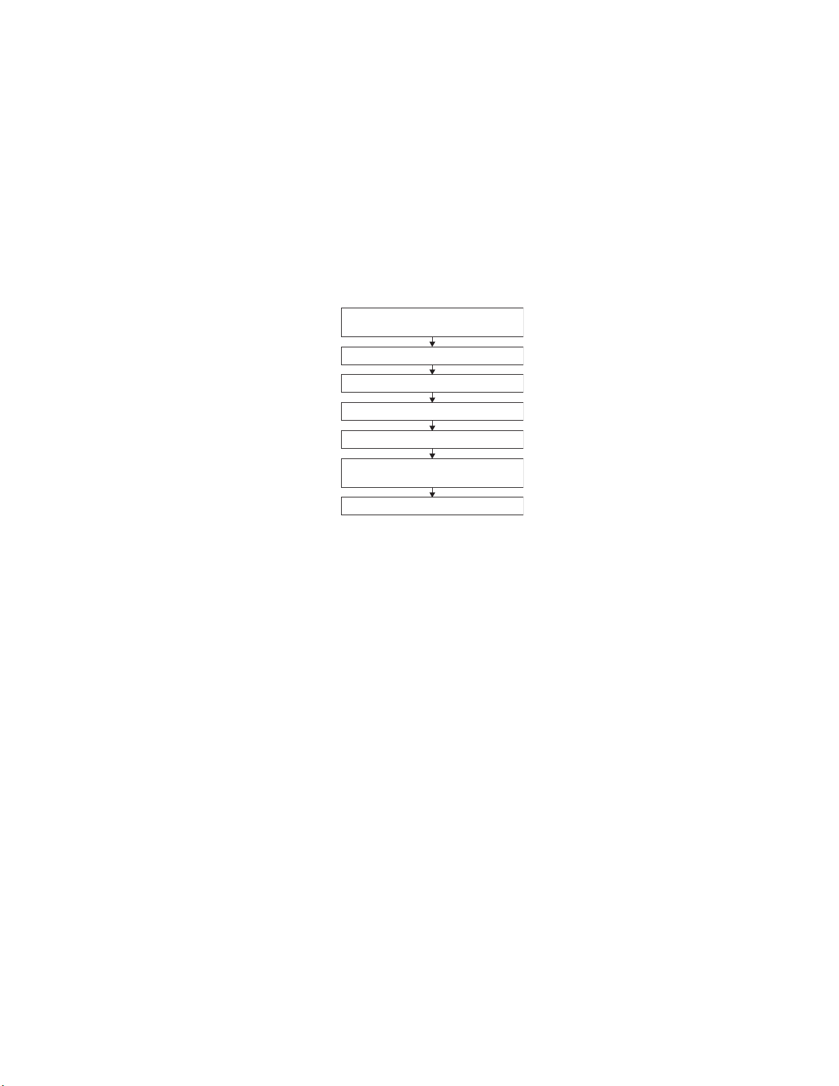
13.1.1 Internal Setting Temperature
Once the operation starts, remote control setting temperature will be taken as base value for temperature shifting
processes. These shifting processes are depending on the air conditioner settings and the operation environment.
The final shifted value will be used as internal setting temperature and it is updated continuously whenever the
electrical power is supplied to the unit.
Remote Control Setting Temperature
Outdoor Air Temperature Shifting
60.8°F - 86°F
Auto Operation Mode Shifting
Indoor Air Temperature Shifting
Powerful Mode Shifting
Setting Temperature Limit Checking
(Min: 60.8°F; Max 91.4°F)
Internal Setting Temperature
13.1.2 Cooling Operation
13.1.2.1 Thermostat control
Compressor is OFF when intake Air Temperature - Internal Setting Temperature < 2.7°F.
Compressor is ON after waiting for 3 minutes, if the Intake Temperature - Internal Setting Temperature >
Compressor OFF point.
13.1.3 Soft Dry Operation
13.1.3.1 Thermostat control
Compressor is OFF when Intake Temperature - Internal Setting Temperature < -3.6°F.
Compressor is ON after waiting for 3 minutes, if the Intake Air Temperature - Internal Setting Temperature >
Compressor OFF point.
13.1.4 Heating Operation
13.1.4.1 Thermostat control
Compressor is OFF when Intake Temperature - Internal Setting Temperature > 3.6°F.
Compressor is ON after waiting for 3 minutes, if the Intake Air Temperature - Internal Setting Temperature <
Compressor OFF point
49
Page 3
13.1.4.2 Automatic Operation (For Single Split Connection Only)
y
This mode can be set using remote control and the operation is decided by remote control setting temperature,
remote control operation mode and indoor intake air temperature.
During operation mode judgment, indoor fan motor (with speed of Lo-) is running for 30 seconds to detect the
indoor intake air temperature.
Every 10 minutes, the indoor temperature is judged.
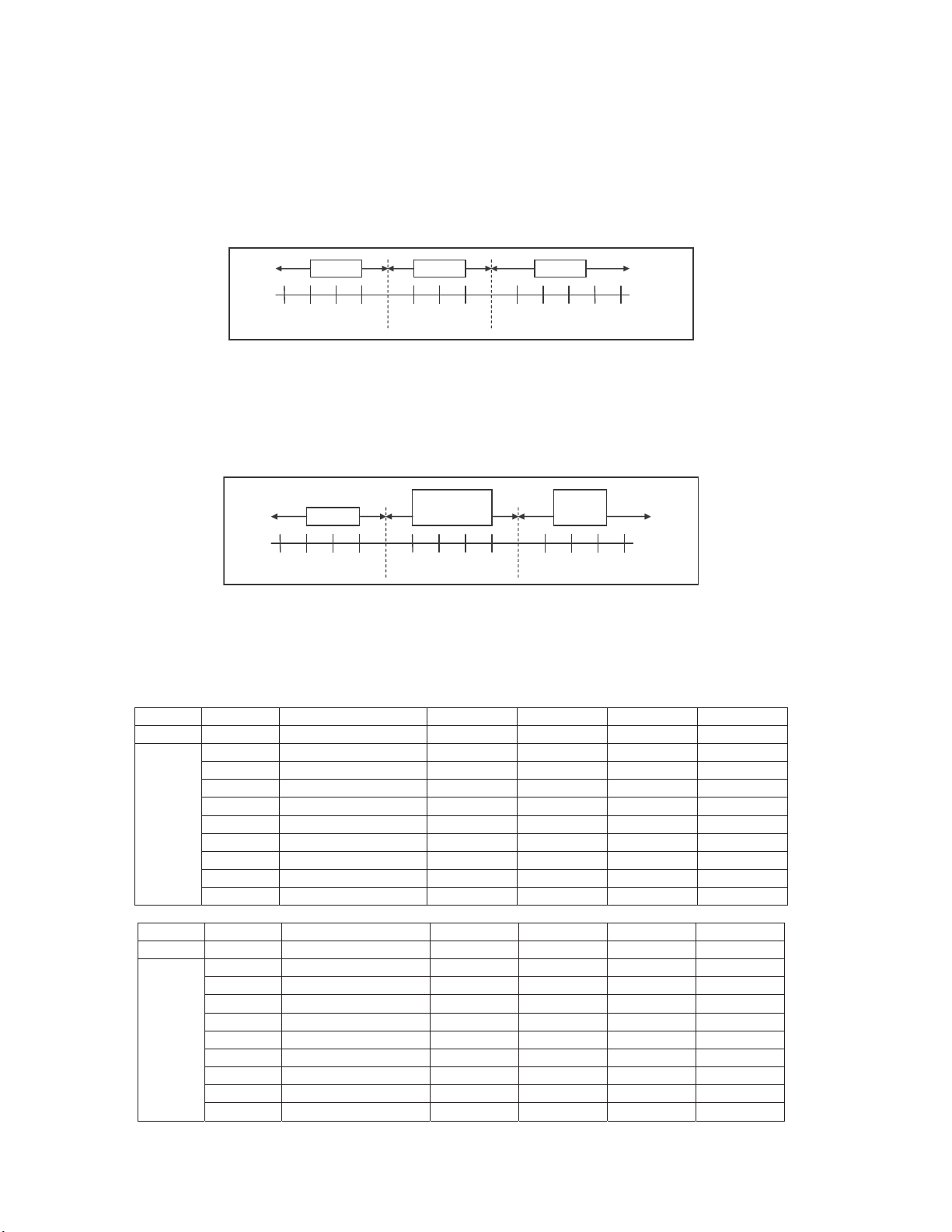
For the 1st judgment
o If indoor intake temperature - remote control setting temperature 3.6°F, COOL mode is decided.
o If -3.6°F indoor intake temperature - remote control setting temperature < 3.6°F, DRY mode is decided.
o If indoor intake temperature - remote control setting temperature < -3.6°F , HEAT mode is decided.
Heat Dr
-10.8 -9.0 -7.2 -5.4 -3.6 -1.8 1.8 3.6 5.4 7.2 9.0 10.80
Cool
For the 2nd judgment onwards
o If indoor intake temperature - remote control setting temperature 5.4°F, if previous operate in DRY mode,
then continue in DRY mode. otherwise COOL mode is decided.
o If -3.6°F indoor intake temperature - remote control setting temperature < 5.4°F, maintain with previous
mode.
o If indoor intake temperature - remote control setting temperature < -3.6°F, HEAT mode is decided.
Heat
-10.8 -9.0 -7.2 -5.4 -3.6 -1.8 1.8 3.6 5.4 7.2 9.0 10.80
current mode
Maintain
Cool
/Dry
13.2 Indoor Fan Speed Control
Indoor Fan Speed can be set using remote control.
13.2.1 Fan Speed Rotation Chart
E9RKUAW E12RKUAW E18RKUAW E24RKUAW
Mode Fan Tap Application rpm rpm rpm rpm
SHi Pwr Me+ 1210 1350 1480 1500
Hi Fc, RC 1120 1230 1380 1400
Me+ RC 1010 1110 1300 1320
Me RC 910 1000 1220 1240
COOL
Mode Fan Tap Application rpm rpm rpm rpm
HEAT
Me- RC 810 890 1140 1160
Lo Fcmin, RC 710 780 1060 1090
Lo- QuietLo 610 620 970 1000
SLo Dry 550 560 690 690
SSLo Auto Cut 540 550 580 580
E9RKUAW E12RKUAW E18RKUAW E24RKUAW
SSHi Pwr Me+ 1340 1450 1500 1600
SHi Fh, RC 1250 1380 1410 1500
Me+ RC 1140 1290 1330 1430
Me RC 1040 1210 1260 1360
Me- RC 930 1120 1190 1290
Lo Fhmin, RC 830 1040 1120 1220
Lo- QuietLo 730 940 1030 1110
SLo Thermo Off, Hot start 570 570 430 430
SSLo Thermo Off 560 560 330 330
50
Page 4
13.3 Indoor Fan Motor Operation
H
F
S
M
13.3.1 Basic Rotation Speed (rpm)
Manual Fan Speed
[Cooling, Dry]
o Fan motor’s number of rotation is determined according to remote control setting.
[Heating]
o Fan motor’s number of rotation is determined according to remote control setting.
Auto Fan Speed
[Cooling, Dry]
o According to room temperature and setting temperature, indoor fan speed is determined automatically.
o The indoor fan will operate according to pattern below.
an
peed
igher
edium
Lower
o During operation, indoor fan motor may stop due to odor prevention.
[Heating]
o According to indoor pipe temperature, automatic heating fan speed is determined as follows.
Remote control ż ż ż ż ż
Tab Hi Me+ Me Me- Lo
Remote control ż ż ż ż ż
Tab Shi Me+ Me Me- Lo
[1 pattern : 10 s]
abc def gh
ab
RPM Increased
o
F
102.2
o
F
66.2
Indoor Pipe Temp.
RPM Maintain
RPM Reduced
OFF
95oC
60.8oF
Feedback control
o Immediately after the fan motor started, feedback control is performed once every second.
o During fan motor on, if fan motor feedback 2550 rpm or < 50 rpm continue for 10 seconds, then fan motor
error counter increase, fan motor is then stop and restart. If the fan motor counter becomes 7 times, then
H19 - fan motor error is detected. Operation stops and cannot on back.
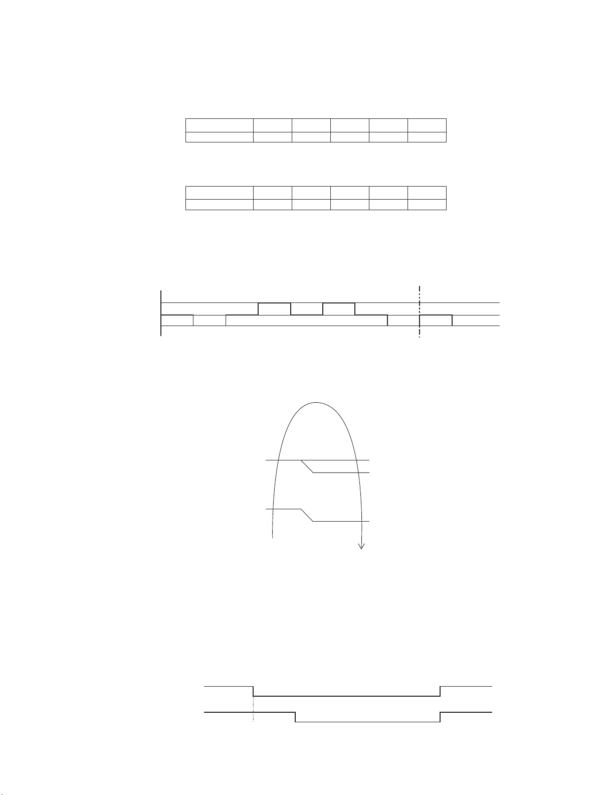
13.4 Outdoor Fan Motor Operation
Outdoor fan motor is operated with fan speed number of rotation. It starts when compressor starts operation and it
stops 30 seconds after compressor stops operation.
ON ON
Compressor OFF
ON Fan Speed ON
Outdoor Fan 30 sec OFF
51
Page 5

13.5 Airflow Direction
0
1
There are two types of airflow, vertical airflow (directed by horizontal vane) and horizontal airflow (directed by
vertical vanes).
Control of airflow direction can be automatic (angles of direction is determined by operation mode, heat
exchanger temperature and intake air temperature) and manual (angles of direction can be adjusted using
remote control).
13.5.1 Vertical Airflow
13.5.1.1 CU-E9RKUA CU-E12RKUA
Operation Mode Airflow Direction
Auto with Heat Exchanger
Heating
Cooling
Soft Dry
Temperature
Manual 20 32 45 57 68
Auto 20 ~ 45
Manual 20 26 32 37 45
Auto 20 ~ 45
Manual 20 26 32 37 45
A 20
B 57
C 32
1 2 3 4 5
13.5.1.2 CU-E18RKUA CU-E24RKUA
Operation Mode Airflow Direction
A 20
B 45
C 32
Heating
Cooling
Soft Dry
Auto with Heat Exchanger
Temperature
Manual 20 32 45 57 68
Auto 20 ~ 45
Manual 20 26 32 37 45
Auto (Anti-Dew Control) 20 ~ 45
Manual (Anti-Dew Control) 20 26 32 37 45
Automatic vertical airflow direction can be set using remote control; the vane swings up and down within the
angles as stated above. For heating mode operation, the angle of the vane depends on the indoor heat
exchanger temperature as Figure 1 below. When the air conditioner is stopped using remote control, the vane
will shift to close position.
Manual vertical airflow direction can be set using remote control; the angles of the vane are as stated above and
the positions of the vane are as Figure 2 below. When the air conditioner is stopped using remote control, the
vane will shift to close position.
36.4°F
96.8°F
Indoor Heat Exchanger
Temperature
C
B
A
122°F
86°F
°
1
2
3
4
1 2 3 4 5
140°
5
Vane angle (°)
Vane angle (°)
Side View
Close position
Figure 2Figure 1
13.5.2 Horizontal Airflow (CU-E9RKUA CU-E12RKUA)
The horizontal airflow direction louvers can be adjusted manually by hand.
52
Page 6

13.5.3 Horizontal Airflow (CU-E18RKUA CU-E24RKUA)
Automatic horizontal airflow direction can be set using remote control; the vane swings left and right within the
angles as stated below. For heating mode operation, the angle of the vane depends on the indoor heat
exchanger temperature as Figure 1 below.
Operation Mode Vane Angle (°)
Heating with heat exchanger temperature
Cooling and Soft Sry 68 ~ 112
A 68 ~ 112
B 90
109.4°F
Indoor Heat Exc hanger
Tem p e ra t u r e
A: swin g
B: fi x front
Figure 1
104.0°F
0°
1
2
3
Figure 2
Top Vi e w
5
4
Manual vertical airflow direction can be set using remote control; the angles of the vane are as stated below and
the positions of the vane are as figure below:
54321nrettaP
Airflow Direction
Patterns at Remote
Control
Vane Angle (° ) 90 68 78 102 112
13.6 Quiet Operation (Cooling Mode/Cooling Area of Dry Mode)
Purpose
o To provide quiet cooling operation compare to normal operation.
Control condition
o Quiet operation start condition
When “Quiet” button at remote control is pressed.
Quiet LED illuminates.
o Quiet operation stop condition
When one of the following conditions is satisfied, quiet operation stops:
POWERFUL/QUIET button is pressed.
Stop by OFF/ON button.
OFF Timer activates.
POWERFUL/QUIET button is pressed again.
When quiet operation is stopped, operation is shifted to normal operation with previous setting.
When fan speed is changed, quiet operation is shifted to quiet operation of the new fan speed.
When operation mode is changed, quiet operation is shifted to quiet operation of the new mode.
During quiet operation, if ON timer activates, quiet operation maintains.
After off, when on back, quiet operation is not memorised.
Control contents
o Auto fan speed is change from normal setting to quiet setting of respective fan speed. This is to reduce
sound of Hi, Me, Lo for 3dB.
o Manual fan speed for quiet operation is -1 step from setting fan speed.
53
Page 7

13.7 Quiet Operation (Heating)
e
air
e
air
Purpose
o To provide quiet heating operation compare to normal operation.
Control condition
o Quiet operation start condition
When “POWERFUL/QUIET” button at remote control is pressed.
Quiet LED illuminates.
o Quiet operation stop condition
When one of the following conditions is satisfied, quiet operation stops:
Stop by OFF/ON button.
Timer “off” activates.
POWERFUL/QUIET button is pressed again.
When quiet operation is stopped, operation is shifted to normal operation with previous setting.
When fan speed is changed, quiet operation is shifted to quiet operation of the new fan speed.
When operation mode is changed, quiet operation is shifted to quiet operation of the new mode.
During quiet operation, if timer “on” activates, quiet operation maintains.
After off, when on back, quiet operation is not memorised.
Control contents
o Fan speed auto
Indoor FM RPM depends on pipe temperature sensor of indoor heat exchanger. Auto fan speed is
changed from normal setting to quiet setting of respective fan speed. This is to reduce sound of Hi, Me,
Lo for 3dB.
o Fan speed manual
Manual fan speed for quiet operation is -1 step from setting fan speed.
13.8 Powerful Mode Operation
When the powerful mode is selected, the internal setting temperature will shift lower up to 3.6°F (for Cooling/Soft
Dry) or higher up to 6.3°F (for Heating) than remote control setting temperature for 20 minutes to achieve the
setting temperature quickly.
13.9 Timer Control
13.9.1 ON Timer Control
ON Timer can be set using remote control, where the unit with timer set will start operation earlier than the setting
time. This is to provide a comfortable environment when reaching the set ON time.
60 minutes before the set ON time, indoor (at fan speed of Lo-) and outdoor fan motor start operation for 30
seconds to determine the indoor intake air temperature and outdoor air temperature in order to judge the
operation starting time.
From the above judgment, the decided operation will start operation earlier than the set time as shown below.
Indoorintak
temperature (oF)
86
77
5min
15 min
10 min
86 95
Cooling/Soft Dry
o
F)
(
Outdoor air
temperature (
Indoorintak
temperature (oF)
59
41
35 min
o
F)
25 min
30 min
32 41
Heating
o
F)
(
Outdoor air
temperature (
o
F)
13.9.2 OFF Timer Control
OFF Timer can be set using remote control, the unit with timer set will stop at set time.
54
Page 8

13.10 Auto Restart Control
When the power supply is cut off during the operation of air conditioner, the compressor will re-operate within
three to four minutes (there are 10 patterns between 2 minutes 58 seconds and 3 minutes 52 seconds to be
selected randomly) after power supply resumes.
This type of control is not applicable during ON/OFF Timer setting.
13.11 Indication Panel
LED POWER TIMER QUIET POWERFUL AUTO COMFORT ECONAVI
Color Green Orange Orange Orange Green Green
Light ON Operation ON Timer Setting ON Quiet Mode ON Powerful Mode ON Auto Comfort ON Econavi Mode ON
Light OFF Operation OFF Timer Setting OFF Quiet Mode OFF Powerful Mode OFF Auto Comfort OFF Econavi Mode OFF
Note:
If POWER LED is blinking, the possible operation of the unit are Hot Start, during Deice operation, operation
mode judgment, or ON timer sampling.
If Timer LED is blinking, there is an abnormality operation occurs.
13.12 ECONAVI and AUTO COMFORT Operation
A Pyoelectric infrared sensor is used to detect injection strength variation of infrared at setting area to determine
the presence or absence of human and its activity level. Human detection area is shown in figure below:
Top Vi ew
90°
2m
Angle of detection
7m
Area of detection
ECONAVI and AUTO COMFORT operation – Human presence/absence detection outlined flow
Process infrared sensor output signal
Human detection (movement) every 3 seconds.
ź
Human detection records
Records human detection (movement) result for 30 seconds and determine its activity level i.e. Hi/Lo.
ź
Presence / absence detection
Compares current and previous human detection result every 30 seconds to determine the presence
or absence of human.
ź
Presence / absence determination
Based on human presence / absence detection, if human presence detection showed within
30 minutes, it is recognised that human is present. If human absence detection showed continuously
for more than 30 minutes, it is recognised that no human is present.
ECONAVI and AUTO COMFORT Sensor abnormality detection
1. Connector pulled out (disconnected), Wire cut Abnormality (Fix Output at Hi)
a. Abnormal judgment start condition.
Start from ECONAVI and AUTO COMFORT Sensor power ON, and end after 30 seconds.
b. Control content.
Judge ECONAVI and AUTO COMFORT Sensor power level every 100ms.
c. Abnormal Judgment condition.
When ECONAVI and AUTO COMFORT Sensor has continues for 25 seconds Hi level.
55
Page 9

2. Circuit Abnormal (Fix Output Lo)
a. Abnormal judgment start condition.
After ECONAVI and AUTO COMFORT Sensor unit power ON, and after pressed 70 seconds.
b. Control content.
Judge ECONAVI and AUTO COMFORT Sensor power level every 100ms.
c. Abnormal Judgment condition.
When ECONAVI and AUTO COMFORT Sensor has continues at Lo level for 25 seconds.
3. Abnormal treatment
Any one of the above self-diagnosis result is abnormal
Abnormal counter +1 and ECONAVI and AUTO COMFORT Sensor power supply OFF.
After ECONAVI and AUTO COMFORT Sensor unit power is OFF for 5 seconds, Retry the ECONAVI and
AUTO COMFORT operation.
When Abnormal counter reach 4 counts, ECONAVI and AUTO COMFORT sensor abnormality is
confirmed.
(Abnormal counter is cleared when sensor power ON and maintain normal for 120 seconds and above or
Clear Abnormal counter by power reset)
Save ECONAVI and AUTO COMFORT Sensor Abnormality H59 (no Timer LED blinking).
ECONAVI & AUTO COMFORT Sensor operation OFF, but ECONAVI and AUTO COMFORT LED
maintain ON.
The unit still operate as normal.
Sensor error counter can be cleared only after power supply reset or AC Reset button on the remote
control is pressed.
ECONAVI and AUTO COMFORT Demo Mode
To enable ECO DEMO mode, during unit is OFF (power standby):
Remote control normal mode
Press continously for 5s
SET
SET
Transmit ECO demo code
and after 30 seconds return to normal
mode.
TEMP
TEMP
SET
Transmit sunlight sensor check code
and after 30 seconds return to normal
mode.
TEMP
TEMP
SET
Transmit check code
and after 30 seconds return to normal
mode.
To disable ECO Demo MODE:
Transmit ECO Demo signal again.
Control details:
During ECONAVI and AUTO COMFORT Demo mode, operation LED ON and horizontal vane will set to Auto
Swing.
When Hi activity judge, Fan speed change to Hi Fan and ECONAVI and AUTO COMFORT LED ON.
When Lo activity judge, Fan speed change to Lo Fan and ECONAVI and AUTO COMFORT LED OFF.
No setting temperature adjustment.
During ECONAVI and AUTO COMFORT operation, the internal setting temperature and fan speed are adjusted
in order to provide comfort and energy saving.
56
Page 10

ECONAVI Start condition.
V
Press ECONAVI button.
ECONAVI Stop condition.
Press ECONAVI button again.
OFF Timer activates.
Press OFF/ON button to turn off the air conditioner.
Press AUTO OFF/ON button to turn off the air conditioner.
Press POWERFUL/QUIET button.
AUTO COMFORT Start condition.
Press AUTO COMFORT button.
AUTO COMFORT Stop condition.
Press AUTO COMFORT button again.
OFF Timer activates.
Press OFF/ON button to turn off the air conditioner.
Press AUTO OFF/ON button to turn off the air conditioner.
Press POWERFUL/QUIET button.
ECONAVI and AUTO COMFORT operation could ON when any of the following conditions is fulfilled:
During forced cooling or forced heating operation.
Power Failure
ECONAVI and AUTO COMFORT operation will be resuming after recovered from power failure.
Timer Operation
When unit is turn on by ON Timer and ECONAVI and AUTO COMFORT operation is ON during previous
operation before OFF, ECONAVI and AUTO COMFORT operation will not be ON automatically.
When unit is turn on by ON Timer and ECONAVI and AUTO COMFORT operation is OFF during
previous operation before OFF, ECONAVI and AUTO COMFORT operation will not be ON automatically.
Other Information
ECONAVI and AUTO COMFORT, Powerful, Quiet and Mild Dry Cooling cannot be operated at the same
time.
ECONAVI and AUTO COMFORT sensor initialized time is 70 seconds from power supplied to ECONAVI
and AUTO COMFORT sensor, or 70 seconds from the operation start.
Setting Temperature and Fan Speed Shift
Mono Sensor
I ; Detecting human presence and activity, the unit controls room temperature to save energy.
ECONA
Mode
COOL/DRY
HEAT
AUTO COMFORT ; Detecting human presence and activity, the unit controls room temperature to keep human
comfortable consistently.
Mode
COOL/DRY
HEAT
* During low activity, fan speed 1 tap up for first 15 minutes or until set temperature is reached.
** During human absence, maximum fan speed for COOL/DRY mode is medium fan.
Human
Set
temperature
Human
Set
temperature
Set
Fan Speed
Low activity Normal activity
+2°F / +1 °C
Low activity Normal activity
+2°F / +1 °C
+0.5°F / +0. 3°C
+1 tap*
High activity Absent
-4°F / -2°C
High activity Absent
-2°F / -1°C
-4°F / -2°C
+1 tap
+4°F /
+2°C
-4°F /
-2°C
+4°F /
+2°C
-4°F /
-2°C
57
Page 11

13.12.1 Human Activity Sensor Check Mode
To enable Human Activity sensor abnormality check mode, during ECONAVI operation ON:
Remote control normal mode
Press continously for 5s
SET
SET
Tra nsmit ECO de mo code
and after 30 seconds return to normal
mode.
TEMP
TEMP
SET
Transmit sunlight sensor check code
and after 30 seconds return to normal
mode.
TEMP
TEMP
SET
Transmit check code
and after 30 seconds return to normal
mode.
During ECONAVI is ON, when CHECK signal received, if either sensors has abnormality, the 4 times abnormality
counter is ignored, ECONAVI Indicator will blink immediately and error code is memorized.
The unit could operate without ECONAVI or AUTO COMFORT.
The ECONAVI indicator blinking could be cancelled by pressing ECONAVI button again.
If the human activity sensor has no abnormality, the CHECK process will end and continue with normal operation.
58
Page 12

14. Operation Control (For Multi Split Connection)
During multi split connection, indoor unit’s operation controls are same with single split connection unless specified in
this chapter.
14.1 Cooling operation
14.1.1 Thermostat control
Capability supply to indoor unit is OFF (Expansion valve closed) when Intake Air Temperature — Internal setting
temperature < 28.4°F.
Capability resume supply to indoor unit after waiting for 3 minutes, if the Intake Air temperature — Internal setting
temperature > Capability supply OFF point.
14.2 Soft Dry Operation
14.2.1 Thermostat control
Capability supply to indoor unit is OFF (Expansion valve closed) when Intake Air Temperature Ϋ Internal setting
temperature < 26.6°F.
Capability resume to indoor unit after waiting for 3 minutes, if the Intake Air temperature Ϋ Internal setting
temperature > Capability supply OFF point.
14.3 Heating Operation
14.3.1 Thermostat control
Capability supply to indoor unit is OFF (Expansion valve closed) when Intake Air Temperature Ϋ Internal setting
temperature > 33.8°F.
During this condition, the indoor fan is stopped if compressor is ON.
Capability resume supply to indoor unit after waiting for 3 minutes, if the Intake Air Temperature Ϋ Internal
setting temperature < Capability supply OFF point.
14.3.2 Temperature Sampling Control
Temperature sampling is controlled by outdoor unit where room temperature for all power supply ON indoor unit
could be obtained.
When capability supply to the indoor unit is OFF and the compressor is ON during heating operation, the indoor
fan motor is stopped. During this condition, 15 seconds after sampling signal from outdoor unit is received, the
indoor fan start operation at low fan speed.
However, within first 4 minutes of capability stopped supply to the indoor unit, even sampling signal is received,
the sampling control is cancelled.
59
Page 13

14.4 Automatic Operation (For Multi Split Connection Only)
This mode can be set using remote control and the operation is decided by remote control setting temperature,
remote control operation mode, indoor intake and outdoor air temperature.
During operation mode judgment, indoor fan motor (with speed of -Lo) and outdoor fan motor are running for
30 seconds to detect the indoor intake and outdoor air temperature. The operation mode is decided based on
below chart.
Indoor intake air
temperature (F)
96.8
60.8
Heating Mode
Soft Dry Mode
T1
T2
T3
66.255.4 69.8 73.4 77
Outdoor air
temperature (F)
Cooling Mode
Remote Control
setting temperature
Every 180 minutes, the indoor and outdoor temperature is judge. Based on remote control setting temperature,
the value of T1 will increase up to 50°F, T2 will decrease by 37.4°F and T3 will decrease up to 46.4°F.
14.5 Indoor Fan Motor Operation
14.5.1 Residual Heat Removal Control
To prevent high pressure at indoor unit, when heating mode thermostat-off condition or power supply OFF,
indoor fan continue to operate at controlled fan speed for maximum 30 seconds then stop.
14.6 Powerful Mode Operation
When the power mode is selected, the internal setting temperature will shift lower up to 39.2F for Cooling/Soft
Dry or higher up to 42.8°F for heating than remote control setting temperature, the powerful operation continue
until user cancel the Powerful operation by pressing powerful button again.
14.7 Auto restart control
When the power supply is cut off during the operation of air conditioner, the compressor will re-operate between
three to four minutes (10 patterns to be selected randomly) after power resume.
During multi split connection, Indoor unit will resume previous mode, include unit standby mode.
14.8 Indication Panel
LED POWER TIMER QUIET POWERFUL AUTO COMFORT ECONAVI
Color Green Orange Orange Orange Green Green
Light ON Operation ON Timer Setting ON Quiet Mode ON Powerful Mode ON Auto Comfort ON Econavi Mode ON
Light OFF Operation OFF Timer Setting OFF Quiet Mode OFF Powerful Mode OFF Auto Comfort OFF Econavi Mode OFF
Note:
If POWER LED is blinking (0.5 second ON, 0.5 second OFF), the possible operation of the unit are during Indoor
Residual Heat Removal, Hot Start, during Deice operation, operation mode judgment, or ON timer sampling.
If POWER LED is blinking (2.5 seconds ON, 0.5 second OFF), the unit is in standby mode.
If TIMER LED is blinking, there is an abnormality operation occurs.
60
 Loading...