

Panasonic cs-e9nkuw installation
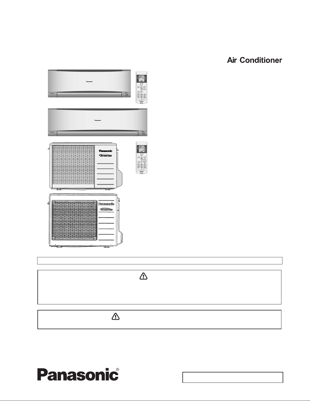
Order No: PHAAM1111084C1
Installation Manual
Indoor Unit Outdoor Unit
CS-S9NKUW-1
CS-S12NKUW-1
CS-S18NKU-1
CS-S22NKU-1
CU-S9NKU-1
CU-S12NKU-1
CU-S18NKU-1
CU-S22NKU-1
Please file and use this manual together with the service manual for Model No. CU-2S18NBU, Order No. PHAAM1111121C1.
WARNING
This service information is designed for experienced repair technicians only and is not designed for use by the general public.
It does not contain warnings or cautions to advise non-technical individuals of potential dangers in attempting to service a product.
Products powered by electricity should be serviced or repaired only by experienced professional technicians. Any attempt to
service or repair the products dealt with in this service information by anyone else could result in serious injury or death.
PRECAUTION OF LOW TEMPERATURE
In order to avoid frostbite, be assured of no refrigerant leakage during the installation or repairing of refrigerant circuit.
© Panasonic HA Air-Conditioning (M) Sdn. Bhd. 2011.
Unauthorized copying and distribution is a violation of law.
10. Installation Instruction
10.1 S9NKUW-1 S12NKUW-1
10.1.1 Select the Best Location
10.1.1.1 Indoor Unit
x Do not install the unit in excessive oil fume area
such as kitchen, workshop
There should not be any heat source or
x
near the unit.
x
There should not be any obstacles blocki
circulation.
x
A place where air circulation in the room
x
A place where drainage can be ea
A place where noise prevention is taken
x
c
onsiderat
Do not install the unit near a door
x
x Ensure the spaces indicated by arrows from the
wall, ceili
Recommended installation height for ind
x
shall be at least 8.2 ft.
ion.
ng, fence or other obstacles
and etc.
steam
ng the air
is good.
sily done.
into
way.
.
oor unit
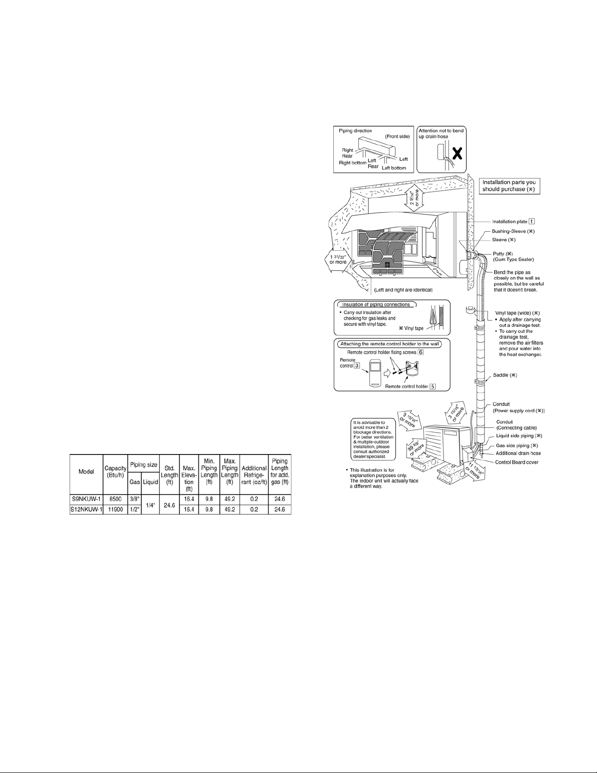
10.1.1.2 Outdoor Unit
x If an awning is built over the unit to prevent direct
sunli
ght or rain, be careful that heat radiat
the con
x There should not be any animal or plant which
coul
Keep the spaces indicated by arrows from
x
ceiling, fence or other obstacles.
x
Do not place any obstacles
sho
x
If piping length is over the [piping length
addition
adde
denser is not obstru
d be affected by hot air discharg
rt circuit of the discharg
al gas], additional refrigerant sh
d as shown in the tabl
cted.
which may cause a
ed air.
e.
ion from
ed.
wall,
for
ould be
10.1.2 Indoor/Outdoor Unit Installation
Diagram
Example: For S9NKUW-1
If the unit is installe
additional refrigerant should be 1.64 oz .... (32.8 - 24.6)
ft x 0.2 oz/ft = 1.64 oz.
d at 32.8 ft distance, the quantity of
31
10.1.3 Indoor Unit
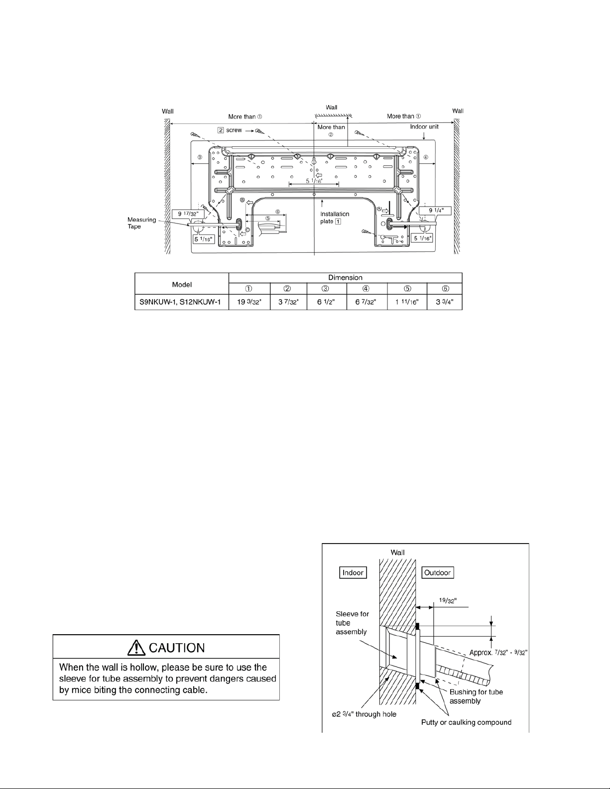
10.1.3.1 How to Fix Installation Plate
The mounting wall shall be strong and solid enough to prevent if from the vibration.
The ce
ntre of installation plate should be at more than c at right and left of the wall.
The distance from installation plate edge to ceiling should more than d.
From installation plate left edge to unit’s left side is e.
From installation plate right edge to unit’s right side is f.
B : For left side piping, piping connection for liquid should be about g from this line.
ƻ
: For left side piping, piping connection for gas should be about h from this line.
1 Mount the installation plate on the wall with 5 screws or more (at least 5 screws).
(If mounting the unit on the concrete wall, consider using anchor bolts.)
o Always mount the installation plate horizontally by aligning the marking-off line with the thread and us
a level gaug
2 Drill the piping plate hole with ø2 ¾” hole-core drill.
o Line according to the left and right side of the installation plate. The meeting point of the extended lin
the cente
above. The h
r
espec
o
Drill the piping hole at either the right or the left and the hole should be slightly slanting to the outdoo
side.
e.
r of the hole. Another method is by putting measuring tape at position as sh
ole center is obtained by measuring the distance namely 5 1/16” for left and righ
tively.
10.1.3.2 To Drill a Hole in the Wall and
Install a Sleeve of Piping
1 Insert the piping sleeve to the hole.
2 Fix the bushing to the sleeve.
3 Cut the sleeve until it extrudes about 19/32”
from the wall.
ing
e is
own in the diagram
t hole
r
4
Finish by sealing the sleeve with putty or
caulking compound at the final stage.
32
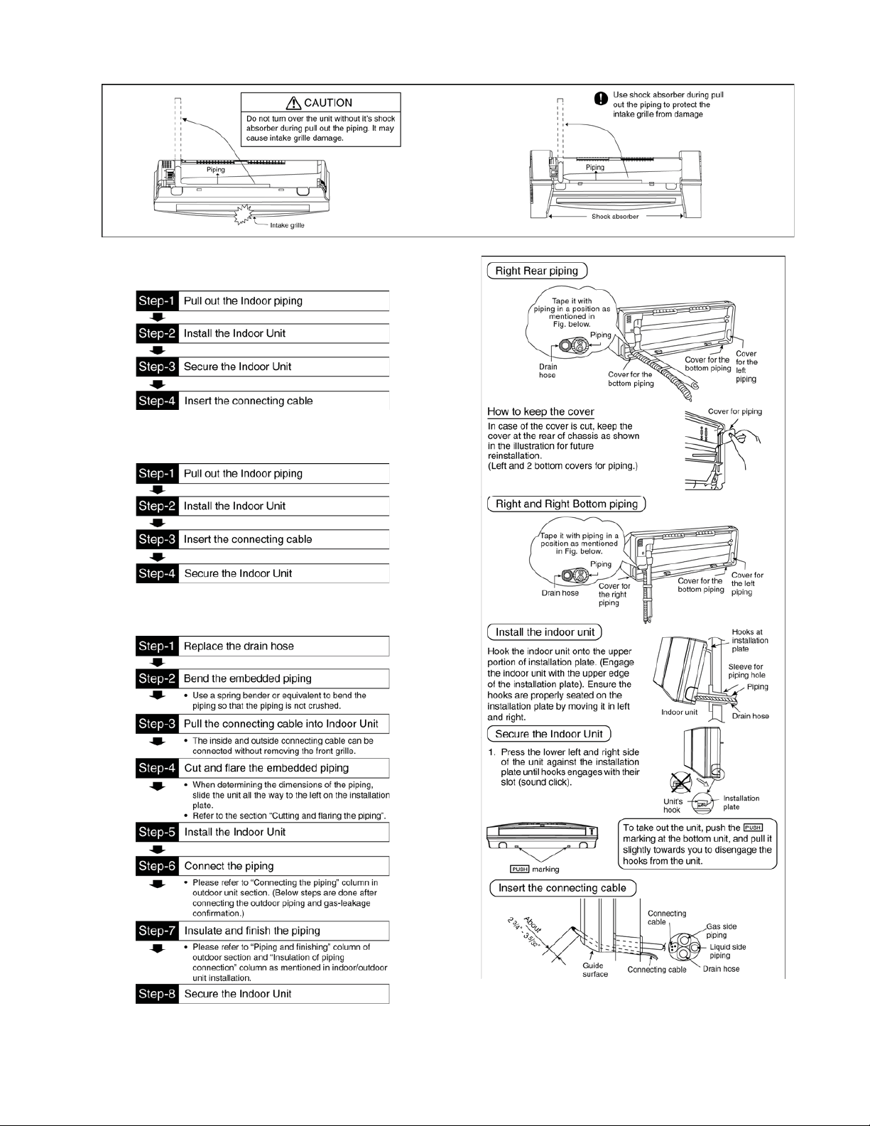
10.1.3.3 Indoor Unit Installation
10.1.3.4 For the right rear piping
10.1.3.5 For the right bottom piping
10.1.3.6 For the embedded piping
(Thi
s can be used for left rear piping and bottom
piping also.)
33
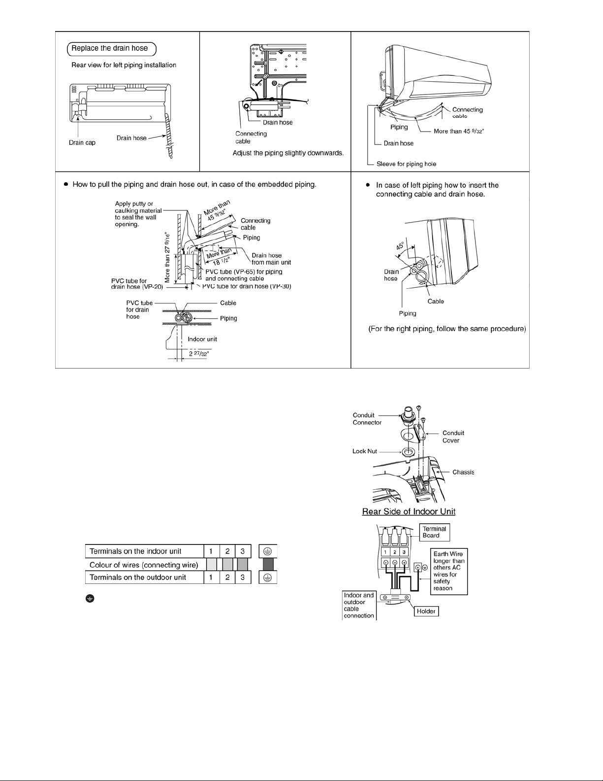
10.1.3.7 Connect the Cable to the Indoor Unit
1. The inside and outside connecting cable can
be co
nnected without remo
Unscrew the conduit cove
2.
nector to conduit cove
con
se
cure it against chassi
3.
Connecting wire between indoor unit an
r unit should be UL listed or
outdoo
approved 4 condu
in accordan
Ensure the colour of wires of outdoor un
o
and terminal number are the same as the
indoo
r's resp
This equipment must be properly earthed.
o Earth lead wire shall be
(Y/G) in colou
other lead wires as shown in the figure fo
electri
cal safety in case of the slip
ctor wires minimum AWG1
ce with local electric code
ectively.
r and shall be longer than
ving the front grille.
r and fix the conduit
r with lock nut, then
s.
d
CSA
6
s.
it
Yellow/Green
r
ping.
34
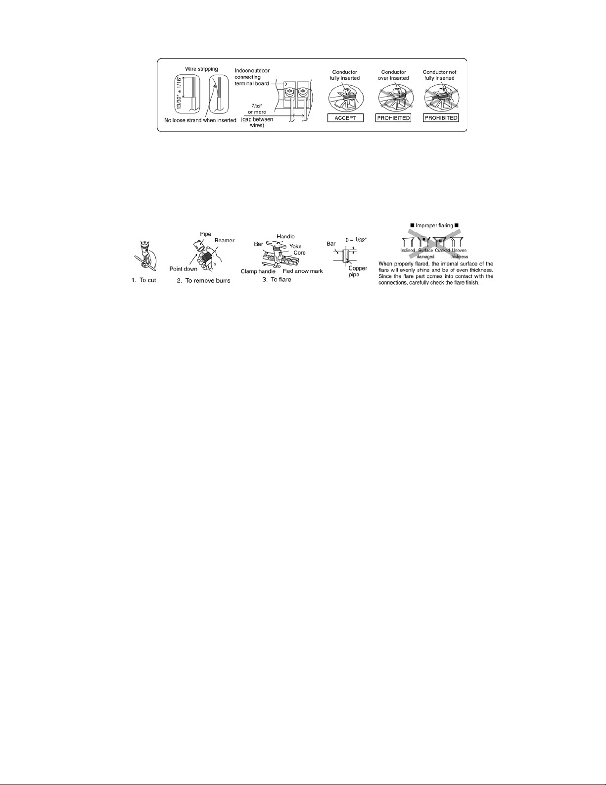
10.1.3.8 Wire Stripping and connecting requirement
10.1.3.9 Cutting and flaring the piping
1 Please cut using pipe cutter and then remove the burrs.
2 Remove the burrs by using reamer. If burrs is not removed, gas leakage may be caused. Turn the piping end
down to avoid the metal powder entering the pipe.
3 Please make flare after inserting the flare nut onto the copper pipes.
35
 Loading...