

Page 1
Order No. MAC0201004C8
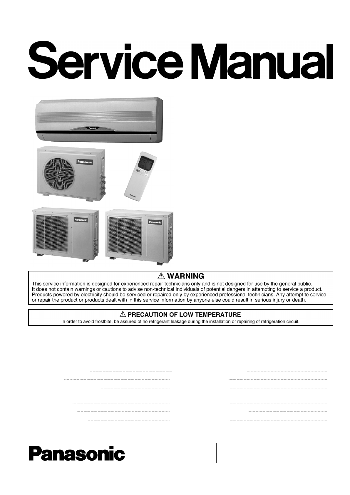
Multi-Split Air Conditioner
CS-C9BKPG CU-2C14BKP5G
CS-C9BKPG CU-2C18BKP5G
CS-C9BKPG CU-3C20BKP5G
CS-C7BKPG CU-2C19BKP5G
CS-C12BKPG
CONTENTS
Page Page
1 Features 2
2 Functions
3 Product Specifications
4 Dimensions
5 Refrigeration Cycle Diagram
6 Block Diagram
7 Wiring Diagram
8 Operation Details
9 Operating Instructions
10 Installation Instructions
11 3-way Valve 49
12 Servicing Information
3
6
13 Troubleshooting Guide
14 Technical Data
14
16
15 Exploded View
18
16 Replacemen t Parts List
17 Exploded View
22
26
18 Replacemen t Parts List
19 Exploded View
34
39
20 Replacemen t Parts List
© 2002 Matsushita Air-Conditioning Corp. Sdn. Bhd.
(183914D). All rights reserved. Unauthorized copying
and distribution is a violation of law.
56
60
62
69
70
71
72
73
74
Page 2

CS-C9BKPG CU-2C14BKP5G / CS-C9BKPG CU-2C18BKP5G / CS-C9BKPG CU-3C20BKP5G / CS-C7BKPG CU-2C19BKP5G / CS-C12BKPG
21 Exploded View 75
22 Replacemen t Parts List
23 Exploded View
76
77
1 Features
High Efficiency
•
Compact Design
•
Comfort Environment
•
8 hours of sleep mode operation
−
Air filter with function to reduce dust and smoke
−
Wider range of horizontal discharge air
−
Auto Restart
•
Random auto restart after power failure for safety restart
−
operation
Removable and Washable Front Panel
•
24 Replacemen t Parts List 78
25 Electronic Parts List
26 Electronic Circuit Diagram
Quality Improvement
•
Gas leakage protection
−
Prevent compressor reverse cycle
−
2-stage OLP to protect compressor
−
Noise prevention during soft dry operation.
−
Anti-dew Formation Control (Cooling & Soft Dry)
−
Operation Improvement
•
Economy mode to reduce electrical power consumption
−
Powerful mode to reach the desired room temperature
−
79
80
quickly
Long Installation Piping
•
Long piping up to 15 meter
−
Remote Control Self-illuminating Button
•
Catechin Air Purifying Filter
•
Trap dust, tobacco smoke and tiny particles
−
Prevent the growth of bacteria and viruses trapped
−
Solar Refreshing Deodorizing Filter
•
Remove unpleasant odour from the air
−
24-hour Timer Setting
•
2
Page 3
2 Functions
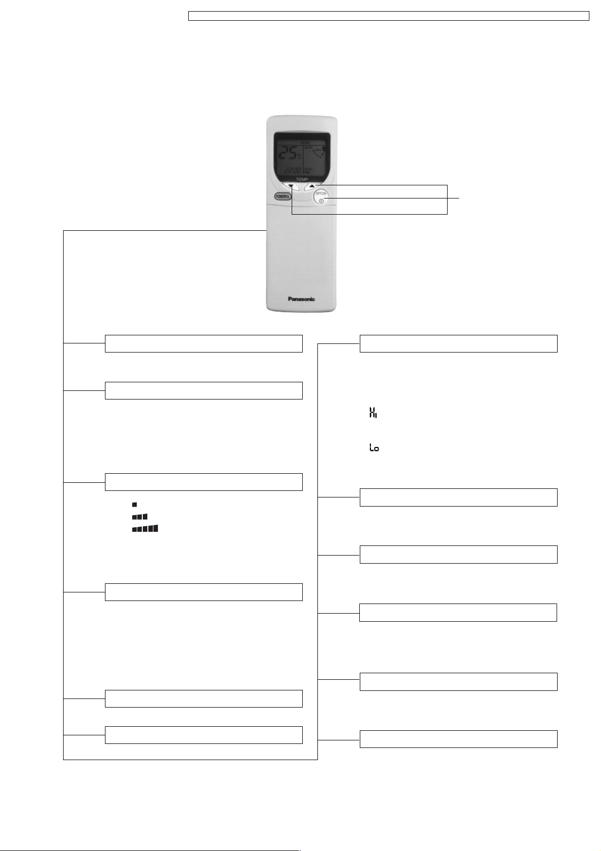
Remote Control
CS-C9BKPG CU-2C14BKP5G / CS-C9BKPG CU-2C18BKP5G / CS-C9BKPG CU-3C20BKP5G / CS-C7BKPG CU-2C19BKP5G / CS-C12BKPG
Self illuminating
button
OFF / ON I
MODE
FAN SPEED
AIR SWING
POWERFUL
Operation OFF / ON
Operation Mode Selection
•
•
•
•
AUTO
COOL
DRY
FAN
Automatic Operation Mode
Cooling Operation Mode
Soft Dry Operation Mode
Air Circulation Mode
Indoor Fan Speed Selection
•
FAN
Low Fan Speed
•
FAN
Medium Fan Speed
•
FAN
High Fan Speed
•
AUTO
FAN
Automatic Fan Speed
Vertical Airflow Direction Control
•
AUTO
Automatic Vertical Airflow
Direction Control
•
MANUAL
Vertical Airflow Direction
Manual Control (5 stages of
adjustment)
Powerful Mode Operation OFF/ON
TEMP.
ON-TIMER
OFF-TIMER
TIME
SET
CANCEL
CLOCK
Room Temperature Setting
Cooling, Soft Dry, Air Circulation Operation.
• Temperature Setting (16°C to 30°C)
Automatic Operation
•
Operation with 2°C higher than
standard temperature.
• Operation with standard temperature.
•
Operation with 2°C lower than
standard temperature.
Timer Operation Selection
• 24-hour, OFF / ON Real Timer Setting.
Time / Timer Setting
• Hours and minutes setting.
Timer Operation Set / Cancel
• ON Timer and OFF Timer setting and
cancellation.
Clock Setting
• Current time setting.
ECONOMY
Economy Mode Operation OFF/ON
3
SLEEP
Sleep Mode Operation OFF / ON
Page 4
CS-C9BKPG CU-2C14BKP5G / CS-C9BKPG CU-2C18BKP5G / CS-C9BKPG CU-3C20BKP5G / CS-C7BKPG CU-2C19BKP5G / CS-C12BKPG
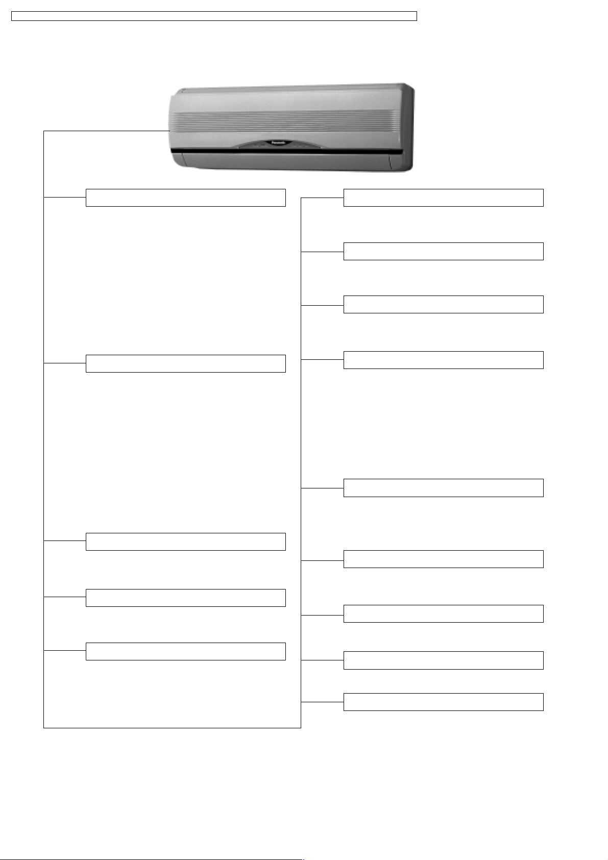
Indoor Unit
AUTO
OFF / ON
Automatic Operation Button
Random Auto Restart Control
• Press for < 5s to operate Automatic
operation mode.
(Used when the remote control cannot be used.)
• Press continuously for 5s or < 10s to
operate Test Run/Pump down. “Beep”
sound will be heard at the 5th second.
(Used when test running or servicing.)
• Press continuously for 10s and above to
omit or resume the remote control signal
receiving sound. “Beep, beep” sound will
be heard at the 10th second.
Operation Indication Lamps (LED)
•
POWER
(Green) ........Lights up in operation,
blinks in Automatic
Operation Mode
judging.
•
SLEEP
(Orange)........ Lights up in Sleep
Mode Operation.
•
TIMER
(Orange) .......Lights up in Timer
Setting.
•
POWERFUL
(Orange)..Lights up in Powerful
Mode Operation.
•
ECONOMY
(Green) ..... Lights up in Economy
Mode Operation.
Operation Mode
• Cooling, Soft Dry, Air Circulation and
Automatic Mode.
Powerful Operation
• Reaches the desired room temperature
quickly.
• Operation is restarted randomly after
power failure at previous setting mode.
Anti-Freezing Control
• Anti-Freezing control for indoor heat
exchanger. (Cooling and Soft Dry)
Sleep Mode Auto Control
• Indoor Fan operates at Low speed.
• Operation stops after 8 hours.
Indoor Fan Speed Control
• High, Medium and Low.
• Automatic Fan Speed Mode
– Cooling : Fan rotates at Hi, Me and
SLo speed. Deodorizing
control is available.
– Soft Dry: Fan rotates at SLo speed.
Deodorizing control
is available.
Airflow Direction Control
• Automatic air swing and manual adjusted
by remote control for vertical airflow.
•
Manually adjusted by hand for horizontal airflow.
Starting Current Control
• Fan motor is delayed for 1.6 seconds
when compressor starts simultaneously.
Time Delay Safety Control
•
Restarting is inhibited for appro. 3 minutes.
Economy Operation
• To reduce electrical power consumption.
7 Minutes Time Save Control
• Cooling Operation only.
Anti-Dew Formation Control
• Anti-Dew Formation Control for indoor
unit discharge area.
4
Page 5
CS-C9BKPG CU-2C14BKP5G / CS-C9BKPG CU-2C18BKP5G / CS-C9BKPG CU-3C20BKP5G / CS-C7BKPG CU-2C19BKP5G / CS-C12BKPG
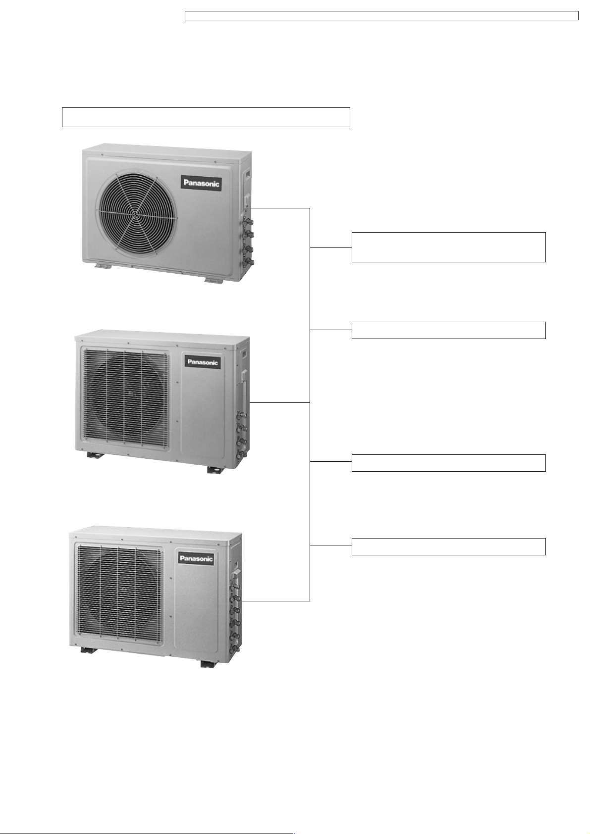
Outdoor Unit
CU-2C14BK, CU-2C18BK, CU-2C19BK & CU-3C20BK
Compressor Reverse Rotation
Protection Control
• To protect compressor from reverse
rotation when there is a instantaneous
power failure.
Overload Protector
• 2-Stage OLP to protect the compressor.
Overload Protector will trip when
– Temperature of compressor increases
to 120°C.
– High temperature or high current flows
to compressor.
(Refer circuit diagram for OLP
characteristic)
60 Secs. Forced Operation Control
• Once the compressor is activated, it
does not stop within the first 60 secs.
However, it stops immediately with
remote control stop signal.
Outdoor Fan Operation Control
• Temperature Fuse.
5
Page 6
CS-C9BKPG CU-2C14BKP5G / CS-C9BKPG CU-2C18BKP5G / CS-C9BKPG CU-3C20BKP5G / CS-C7BKPG CU-2C19BKP5G / CS-C12BKPG
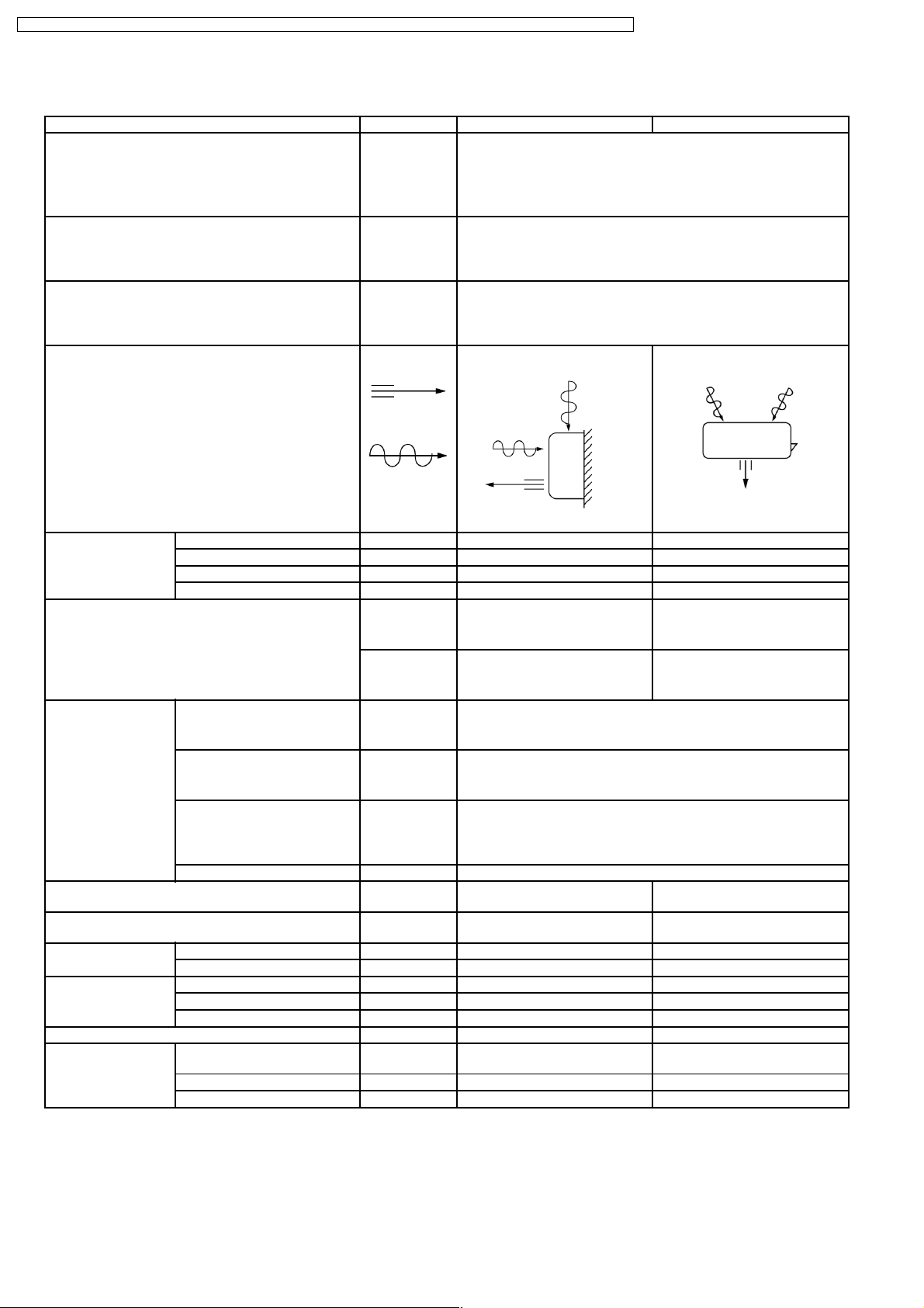
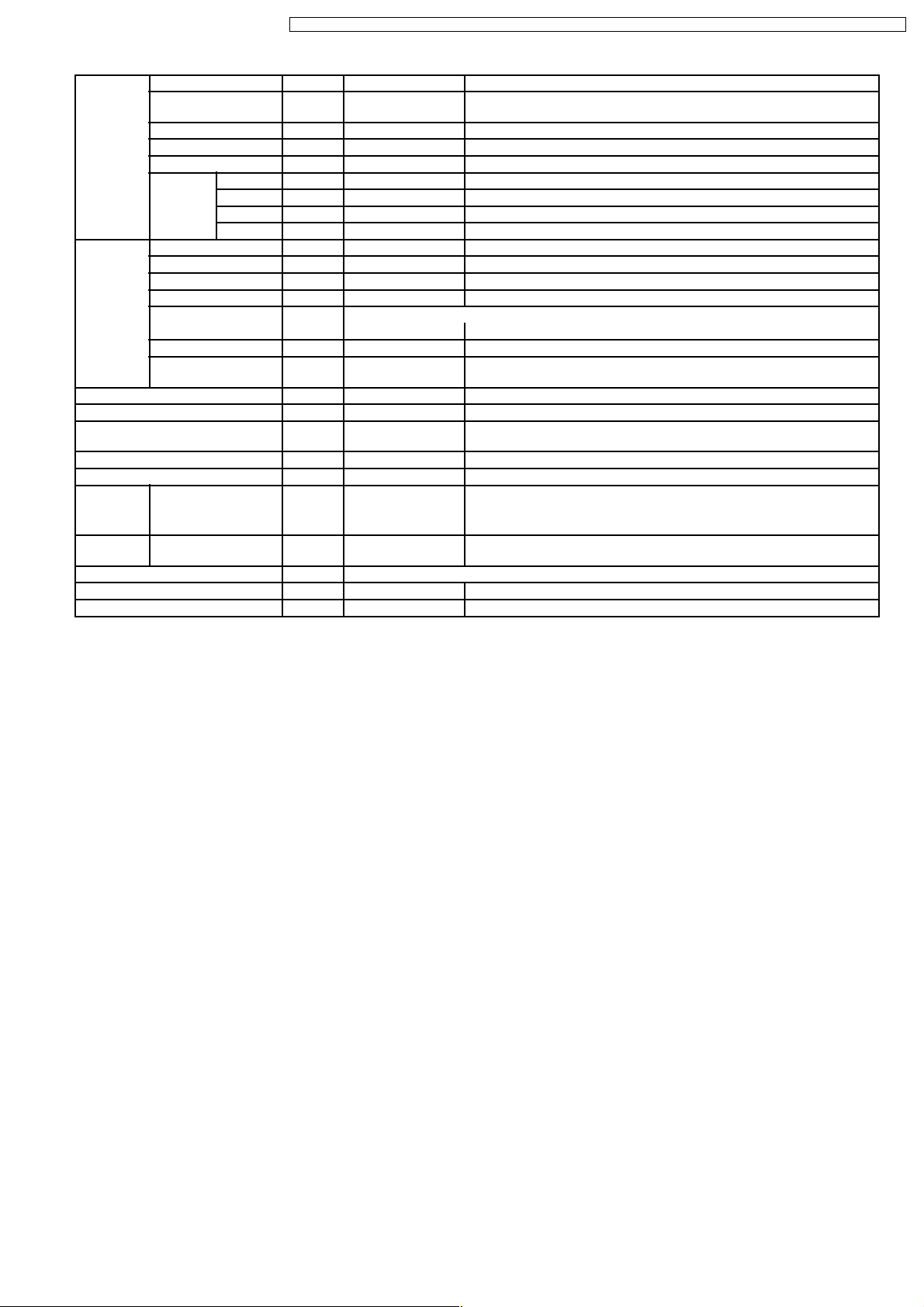
3 Product Specifications
Unit CS-C9BKPG CU-2C14BKP5G
Power Source Phase Single
V Europe: 230 - 220 Oceania: 240 - 220
Cycle 50
Cooling Capacity kW
kcal/h
Moisture Removal l/h
Pint/h
Airflow Method OUTLET
INTAKE
Air Volume Indoor Air (Lo) m3/min (cfm) 6.8 (240) - 6.8 (240) —
Indoor Air (Me) m3/min (cfm) 8.0 (280) - 8.0 (280) —
Indoor Air (Hi) m3/min (cfm) 9.9 (350) - 9.9 (350) —
Indoor Air (SHi) m3/min (cfm) 10.9 (380) - 10.9 (380) —
Noise Level dB (A) High 36 - 36, Low 26 - 26 High 47 - 46
Power level dB High 49 - 49 High 62 - 61
(1 unit) 2.82 - 2.78
2,430 - 2,390
(1 unit) 1.6
3.4
SIDE VIEW TOP VIEW
(2 units) 3.62 - 3.58
(2 units) 2.1
3,110 - 3,080
4.4
Electrical Data Input W (1 unit) 1,150 - 1,100 (2 units) 1,220 - 1,160
Running Current A (1 unit) 5.1 - 5.2 (2 units) 5.4 - 5.5
EER W/W
Starting Current A 20.5 - 19.5
Piping Connection Port
(Flare piping)
Pipe Size
(Flare piping)
Drain
Hose
Dimensions Height inch (mm) 10 - 13/16 (275) 21 - 1/4 (540)
Net Weight lb (kg) 20 (9.0) 77 (35.0)
Compressor Type — Rotary (1 cylinder)
Inner diameter mm 12 —
Length m 0.7 —
Width inch (mm) 31 - 15/32 (799) 29 - 15/16 (760)
Depth inch (mm) 8 - 9/32 (210) 9 - 7/8 (250)
Motor Type — Induction (2-poles)
Rated Output W — 900
kcal/hW
inch
inch
inch
inch
(1 unit) 2.45 - 2.53
2.11 - 2.17
G ; Half Union 3/8”
L ; Half Union 1/4”
G (gas side) ; 3/8”
L (liquid side) ; 1/4”
(2 units) 2.97 - 3.09
2.55 - 2.66
G ; 3-way valve 3/8”
L ; 3-way valve 1/4”
G (gas side) ; 3/8”
L (liquid side) ; 1/4”
rolling piston type
6
Page 7

CS-C9BKPG CU-2C14BKP5G / CS-C9BKPG CU-2C18BKP5G / CS-C9BKPG CU-3C20BKP5G / CS-C7BKPG CU-2C19BKP5G / CS-C12BKPG
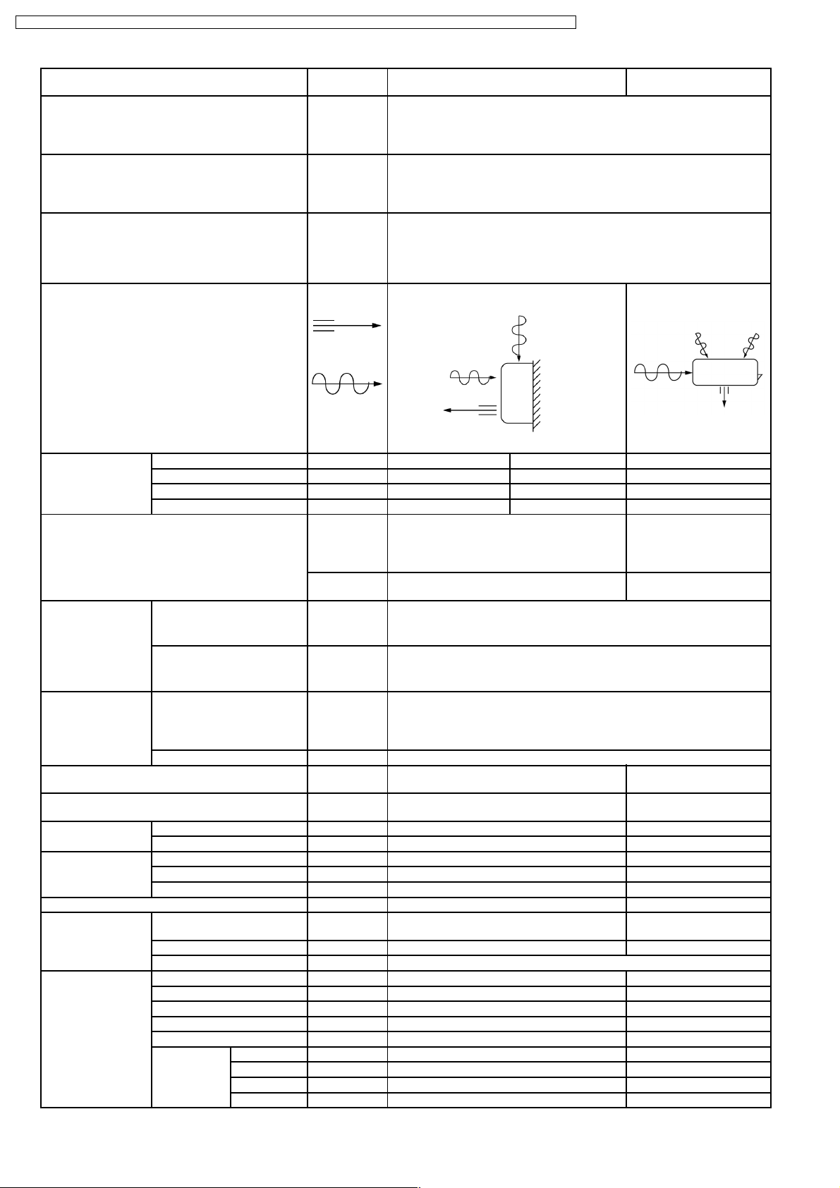
Air Circulation Type Cross-flow Fan Propeller Fan
Material AS + Glass Fiber 20% AS + Glass Fiber 20%
Motor Type Induction (4-poles) Induction (6-poles)
Input W 29.3 - 26.3 41.75 - 36.80
Rated Output W 15 12
Fan Speed Low rpm 780 - 780 —
Medium rpm 920 - 920 —
High rpm 1,140 - 1,140 795 - 750
SuperHigh rpm 1,250 - 1,250 —
Heat Exchanger Description Evaporator Condenser
Tube material Copper Copper
Fin material Aluminium Aluminium
Fin Type Slit Fin Louver Fin
Row / Stage (Plate fin configuration, forced draft)
2×15 1×20
FPI 19 19
Size (W × H × L) mm 610 × 315 × 25.4 687 × 508 × 22
Refrigerant Control Device — Capillary Tube
Refrigeration Oil (c.c) — SUNISO 4GDID or ATMOS M60
Refrigerant (R-22) g (oz) — 890 (31.4)
Thermostat Electronic Control —
Protection Device — Overload Protector
Capillary Tube Length mm — 505
Flow Rate l/min — 17.8
Inner Diameter mm — 1.7
Air Filter Material
Style
Capacity Control Capillary Tube
Compressor Capacitor µF, VAC — 30 µF, 440 VAC
Fan Motor Capacitor µF, VAC 1.5 µF, 400 VAC 1.0 µF, 430 VAC
(c.c) P.P.
Honeycomb
(350)
—
•
Specifications are subject to change without notice for further improvement.
7
Page 8
CS-C9BKPG CU-2C14BKP5G / CS-C9BKPG CU-2C18BKP5G / CS-C9BKPG CU-3C20BKP5G / CS-C7BKPG CU-2C19BKP5G / CS-C12BKPG
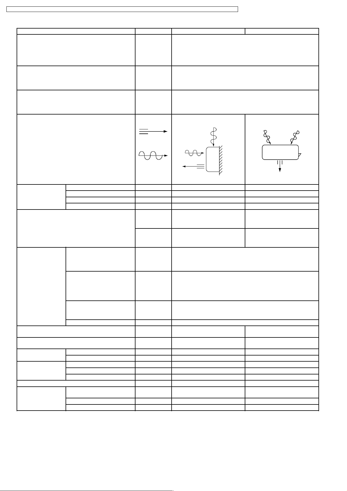
Unit CS-C9BKPG CU-2C18BKP5G
Power Source Phase Single
V Europe: 230 - 220 Oceania: 240 - 220
Cycle 50
Cooling Capacity kW
kcal/h
Moisture Removal l/h
Pint/h
Airflow Method OUTLET
(1 unit) 2.44 - 2.40
(2 units) 4.88 - 4.80
2,100 - 2,060
(1 unit) 1.5
(2 units) 2.6
3.2
SIDE VIEW TOP VIEW
4,200 - 4,130
5.5
INTAKE
Air Volume Indoor Air (Lo) m3/min (cfm) 6.8 (240) - 6.8 (240) —
Indoor Air (Me) m3/min (cfm) 8.0 (280) - 8.0 (280) —
Indoor Air (Hi) m3/min (cfm) 9.9 (350) - 9.9 (350) —
Indoor Air (SHi) m3/min (cfm) 10.9 (380) - 10.9 (380) —
Noise Level dB (A) High 36 - 36, Low 26 - 26 High 55 - 53
Power level dB High 49 - 49 High 70 - 68
Electrical Data Input W (1 unit)
770 - 730
Running Current A (1 unit)
Europe: 3.4 - 3.5
Oceania: 3.3 - 3.5
(2 units)
1,540 - 1,460
(2 units)
Europe: 6.8 - 7.0
Oceania: 6.6 - 7.0
EER W/W (kcal/hW) 3.17 - 3.29 (2.73 - 2.83)
Starting Current A 15.5 - 15.0
Piping Connection Port
(Flare piping)
Pipe Size
(Flare piping)
Drain
Hose
Inner diameter mm 12 —
Length m 0.7 —
inch
inch
inch
inch
G ; Half Union 3/8”
L ; Half Union 1/4”
G (gas side) ; 3/8”
L (liquid side) ; 1/4”
G ; 3-way valve 3/8”
L ; 3-way valve 1/4”
G (gas side) ; 3/8”
L (liquid side) ; 1/4”
Dimensions Height inch (mm) 10 - 13/16 (275) 25 - 21/32 (651)
Width inch (mm) 31 - 15/32 (799) 35 - 3/16 (893)
Depth inch (mm) 8 - 9/32 (210) 13 - 19/32 (345)
Net Weight lb (kg) 20 (9.0) 137 (62)
Compressor Type — Rotary (1 cylinder)
rolling piston type
Motor Type — Induction (2-poles)
Rated Output W — 650
8
Page 9
CS-C9BKPG CU-2C14BKP5G / CS-C9BKPG CU-2C18BKP5G / CS-C9BKPG CU-3C20BKP5G / CS-C7BKPG CU-2C19BKP5G / CS-C12BKPG
Air Circulation Type Cross-flow Fan Propeller Fan
Material AS + Glass Fiber 20% AS + Glass Fiber 20%
Motor Type Induction (4-poles) Induction (6-poles)
Input W 29.3 - 26.3 117.1 - 103.3
Rated Output W 15 43
Fan Speed Low rpm 780 - 780 —
Medium rpm 920 - 920 —
High rpm 1,140 - 1,140 760 - 720
SuperHigh rpm 1,250 - 1,250 —
Heat Exchanger Description Evaporator Condenser
Tube material Copper Copper
Fin material Aluminium Aluminium
Fin Type Slit Fin Louver Fin
Row / Stage (Plate fin configuration, forced draft)
2 × 15 2 × 24
FPI 19 16
Size (W × H × L) mm 610 × 315 × 25.4 560 × 609.6 × 44
Refrigerant Control Device — Capillary Tube
Refrigeration Oil (c.c) — SUNISO 4GDID or ATMOS M60
Refrigerant (R-22) g (oz) — 750 × 2 (26.5 × 2)
Thermostat Electronic Control —
Protection Device — Overload Protector
Capillary Tube Length mm — 680
Flow Rate l/min — 11.5
Inner Diameter mm — 1.5
Air Filter Material
Style
Capacity Control Capillary Tube
Compressor Capacitor µF, VAC — 25 µF, 370 VAC
Fan Motor Capacitor µF, VAC 1.5 µF, 400 VAC 3.0 µF, 450 VAC
(c.c) P.P.
Honeycomb
(270)
—
•
Specifications are subject to change without notice for further improvement.
9
Page 10
CS-C9BKPG CU-2C14BKP5G / CS-C9BKPG CU-2C18BKP5G / CS-C9BKPG CU-3C20BKP5G / CS-C7BKPG CU-2C19BKP5G / CS-C12BKPG
CS-C9BKPG CU-3C20BKP5G
Unit
Single Operation
Single Operation Double Operation Triple
(A, B1, B2)
(A) (B1 or B2) (B1 + B2) (A + B1 or B2) (A + B1 + B2)
Power Source Phase Single
V Europe: 230 - 220 Oceania: 240 - 220
Cycle 50
Operation
Cooling Capacity Per Unit kW
— 2.40-2.34
kcal/h
Moisture Removal l/h
— 1.5
Pint/h
Airflow Method OUTLET
SIDE VIEW TOP VIEW
INTAKE
Air Volume Indoor Air (Lo) m3/min
(cfm)
Indoor Air (Me) m3/min
(cfm)
Indoor Air (Hi) m3/min
(cfm)
Indoor Air (SHi) m3/min
(cfm)
6.8 - 6.8
(240 - 240)
8.0 - 8.0
(280 - 280)
9.9 - 9.9
(350 - 350)
10.9 - 10.9
(380 - 380)
Noise Level dB (A) High 36 - 36,
Low 26 - 26
Power
High 49 - 49 High 71 - 69
level dB
2,060-2,010
3.2
2.82-2.78
2,430-2,390
1.6
3.4
3.60-3.52
3,100-3,030
2.1
4.4
—
—
—
—
High 56 - 54
5.22-5.12
4,490-4,400
2.8
5.9
6.00-5.86
5,160-5,040
3.2
6.8
Electrical
Input W 50 - 50 820-770 1,120-1,070 1,210-1,150 1,850-1,750 1,920-1,840
Data
Running Current A
EER W/W
(kcal/hW)
0.23 - 0.23 3.6 - 3.7
— 2.93 - 3.04
(2.51 - 2.61)
Europe:
5.0 - 5.1
Oceania:
4.9 - 5.1
2.52 - 2.60
(2.17 - 2.23)
Europe:
5.4 - 5.5
Oceania:
5.3 - 5.5
2.98 - 3.06
(2.56 - 2.63)
Starting Current A (A unit) 15.5 - 15.0 (B unit) 21.5 - 21.0
Piping Connection Port
(Flare piping)
Pipe Size
(Flare piping)
Drain
Hose
Inner diameter mm 12 —
Length m 0.7 —
inch
inch
inch
inch
G ; Half Union 3/8”
L ; Half Union 1/4”
G (gas side) ; 3/8”
L (liquid side) ; 1/4”
G;3-wayvalve3/8”
L ; 3-way valve 1/4”
G (gas side) ; 3/8”
L (liquid side) ; 1/4”
Dimensions Height inch (mm) 10 - 13/16 (275) 25 - 21/32 (651)
Width inch (mm) 31 - 15/32 (799) 35 - 3/16 (893)
Depth inch (mm) 8 - 9/32 (210) 13 - 19/32 (345)
Net Weight lb (kg) 20 (9.0) 146 (66)
Compressor Type — Rotary (1 cylinder)
rolling piston type
Motor Type — Induction (2-poles)
Rated Output W — (A unit) 650 (B unit) 900
8.1 - 8.3
2.82 - 2.93
(2.43 - 2.51)
Europe:
8.4 - 8.7
Oceania:
8.3 - 8.7
3.13 - 3.18
(2.69 - 2.74)
10
Page 11
CS-C9BKPG CU-2C14BKP5G / CS-C9BKPG CU-2C18BKP5G / CS-C9BKPG CU-3C20BKP5G / CS-C7BKPG CU-2C19BKP5G / CS-C12BKPG
Air
Circulation
Motor Type Induction (4-poles) Induction (6-poles)
Rated Output W 15 37
Fan Speed Low rpm 780 - 780 —
Heat
Exchanger
Refrigerant Control Device — Capillary Tube
Refrigeration Oil (c.c) — SUNISO 4GDID or ATMOS M60 (320, 270)
Refrigerant (R-22) g (oz) — (A unit) 800 (28.2)
Thermostat Electronic Control —
Protection Device — Overload Protector
Capillary
Tube
Air Filter Material
Capacity Control Capillary Tube
Compressor Capacitor µF, VAC — 25 µF, 440 VAC
Fan Motor Capacitor µF, VAC 1.5 µF, 400 VAC 3.0 µF, 450 VAC
Description Evaporator Condenser
Tube material Copper Copper
Fin material Aluminium Aluminium
Fin Type Slit Fin Louver Fin
Row / Stage (Plate fin configuration, forced draft)
FPI 19 16
Size (W × H × L) mm 610 × 315 × 25.4 756.0
Length mm — 935, 920, 1,170
Flow Rate l/min — 20.0, 15.5, 10.0
Inner Diameter mm — 2.0, 1.8, 1.6
Style
Type Cross-flow Fan Propeller Fan
Material AS + Glass Fiber
20%
Input W 29.3 - 26.3 121.82 - 107.91
Medium rpm 920 - 920 —
High rpm 1,140 - 1,140 765 - 725
SuperHigh rpm 1,250 - 1,250 —
2 × 15 2 × 24
P.P.
Honeycomb
AS + Glass Fiber 20%
× 609.6 × 44
719.5
(B unit) 1,070 (37.7)
—
•
Specifications are subject to change without notice for further improvement.
11
Page 12
CS-C9BKPG CU-2C14BKP5G / CS-C9BKPG CU-2C18BKP5G / CS-C9BKPG CU-3C20BKP5G / CS-C7BKPG CU-2C19BKP5G / CS-C12BKPG
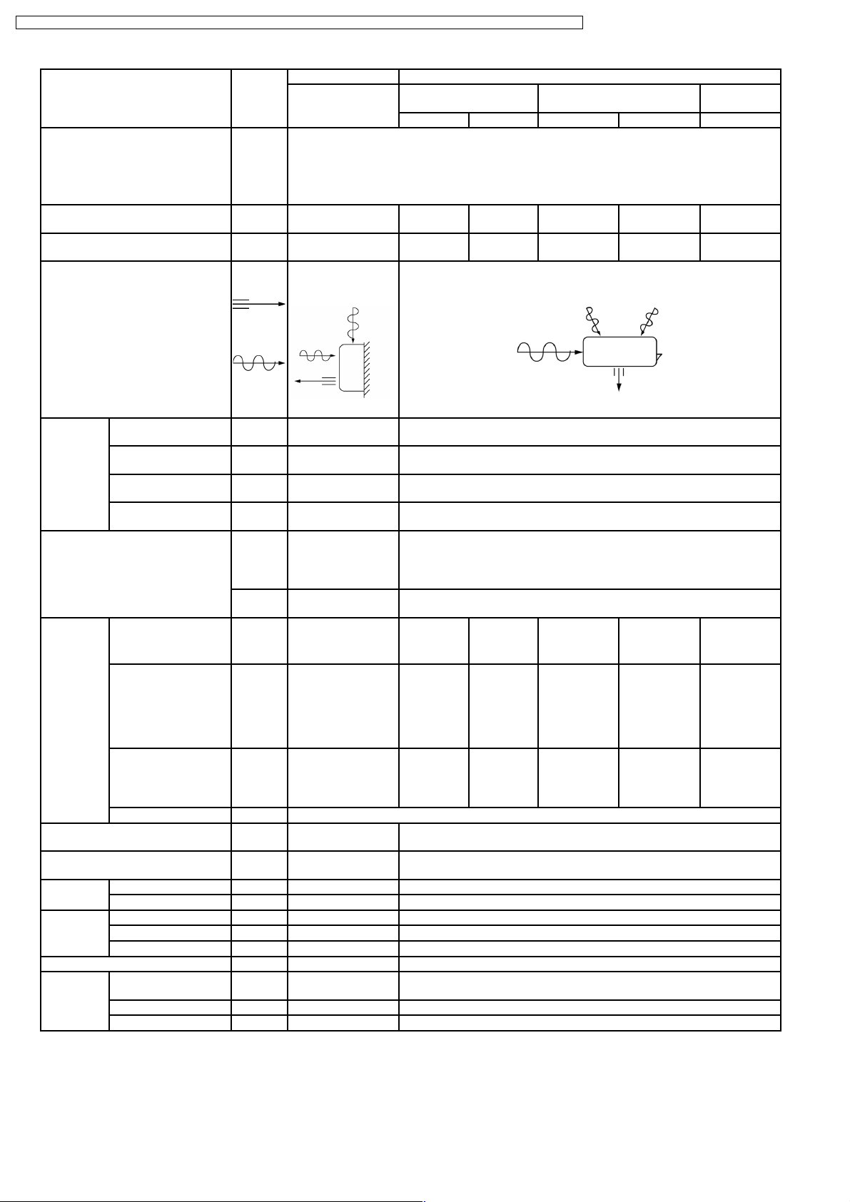
Unit
Cooling Capacity kW
kcal/h
Moisture Removal l/h
Pint/h
Power Source Phase
V
Cycle
Airflow Method OUTLET
One Unit (A)
CS-C12BKPG
(A) 3.55 - 3.52
(A) 3,050 - 3,030
(A) 2.1
4.4
SIDE VIEW TOP VIEW
One Unit (B)
CS-C7BKPG
(B) 2.08 - 2.06
(B) 1,790 - 1,770
(B) 1.4
3.0
Single
230 - 220
50
CU-2C19BKP5G
(A+B) 5.63 - 5.58
(A+B) 4,840 - 4,800
(A+B) 3.1
6.6
INTAKE
Air Volume Indoor Air (Lo) m3/min (cfm) 7.3 - 7.3 (260 - 260) 6.4 - 6.4 (230 - 230) —
Indoor Air (Me) m3/min (cfm) 8.7 - 8.7 (310 - 310) 7.4 - 7.4 (260 - 260) —
Indoor Air (Hi) m3/min (cfm) 10.2 - 10.2 (360 - 360) 8.5 - 8.5 (300 - 300) —
Indoor Air (SHi) m3/min (cfm) 10.5 - 10.5 (370 - 370) 9.4 - 9.4 (330 - 330) —
Noise Level dB (A) (A) High 39 - 39
Low 29 - 29
Power level
(A) High 52 - 52 (B) High 46 - 46 High 70 - 68
(B) High 33 - 33
Low 26 - 26
High 55 - 53
dB
Electrical Data Input W (A) 1,250 - 1,230 (B) 750 - 720 (A+B) 1,880 -1,840
Running Current A (A) 5.7 - 5.9 (B) 3.9 - 3.8 (A+B) 9.0 - 9.1
EER W/W
(kcal/hW)
(A) 2.84 - 2.86
(2.44 - 2.46)
(B) 2.77 - 2.86
(2.39 - 2.46)
(A+B) 2.99 - 3.03
(2.57 - 2.61)
Starting Current A (A) 25 - 24 (B) 15 - 14 (A+B) 40 - 38
Piping Connection Port
(Flare piping)
Pipe Size
(Flare piping)
Drain
Hose
Inner diameter mm 12 —
Length m 0.7 —
inch
inch
inch
inch
G ; Half Union 1/2”,3/8”
L ; Half Union 1/4”, 1/4”
G (gas side) ; 1/2”,3/8”
L (liquid side) ; 1/4”, 1/4”
G ; 3-way valve 1/2”,3/8”
L ; 3-way valve 1/4”,1/4”
G (gas side) ; 1/2”,3/8”
L (liquid side) ; 1/4”,1/4”
Dimensions Height inch (mm) 10 - 13/16 (275) 25 - 21/32 (651)
Width inch (mm) 31 - 15/32 (799) 35 - 3/16 (893)
Depth inch (mm) 8 - 9/32 (210) 13 - 19/32 (345)
Net Weight lb (kg) 20 (9.0) 148 (67)
Compressor Type — Rotary (1 cylinder)
rolling piston type
Motor Type — Induction (2-poles)
Rated Output W (A) 1,100 (B) 600 (A+B) 1,700
Air Circulation Type Cross-flow Fan Propeller Fan
Material AS + Glass Fiber 20% AS + Glass Fiber 20%
Motor Type Induction (4-poles) Induction (6-poles)
Input W (A) 28.7 - 27.1 (B) 20.6 - 19.1 121.82 - 107.91
Rated Output W (A) 15 (B) 10 37
Fan Speed Low rpm (A) 900 - 900 (B) 780 - 780 —
Medium rpm (A) 1,080 - 1,080 (B) 900 - 900 —
High rpm (A) 1,260 - 1,260 (B) 1,030 - 1,030 740 - 725
SuperHigh rpm (A) 1,300 - 1,300 (B) 1,140 - 1,140 —
12
Page 13
CS-C9BKPG CU-2C14BKP5G / CS-C9BKPG CU-2C18BKP5G / CS-C9BKPG CU-3C20BKP5G / CS-C7BKPG CU-2C19BKP5G / CS-C12BKPG
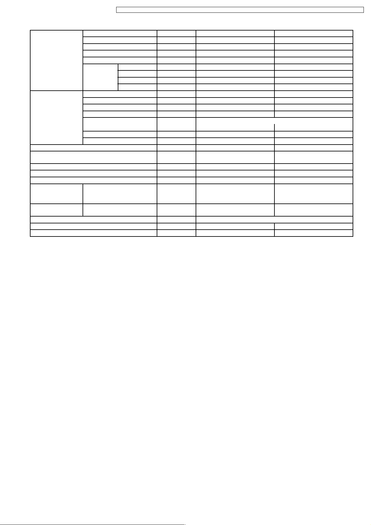
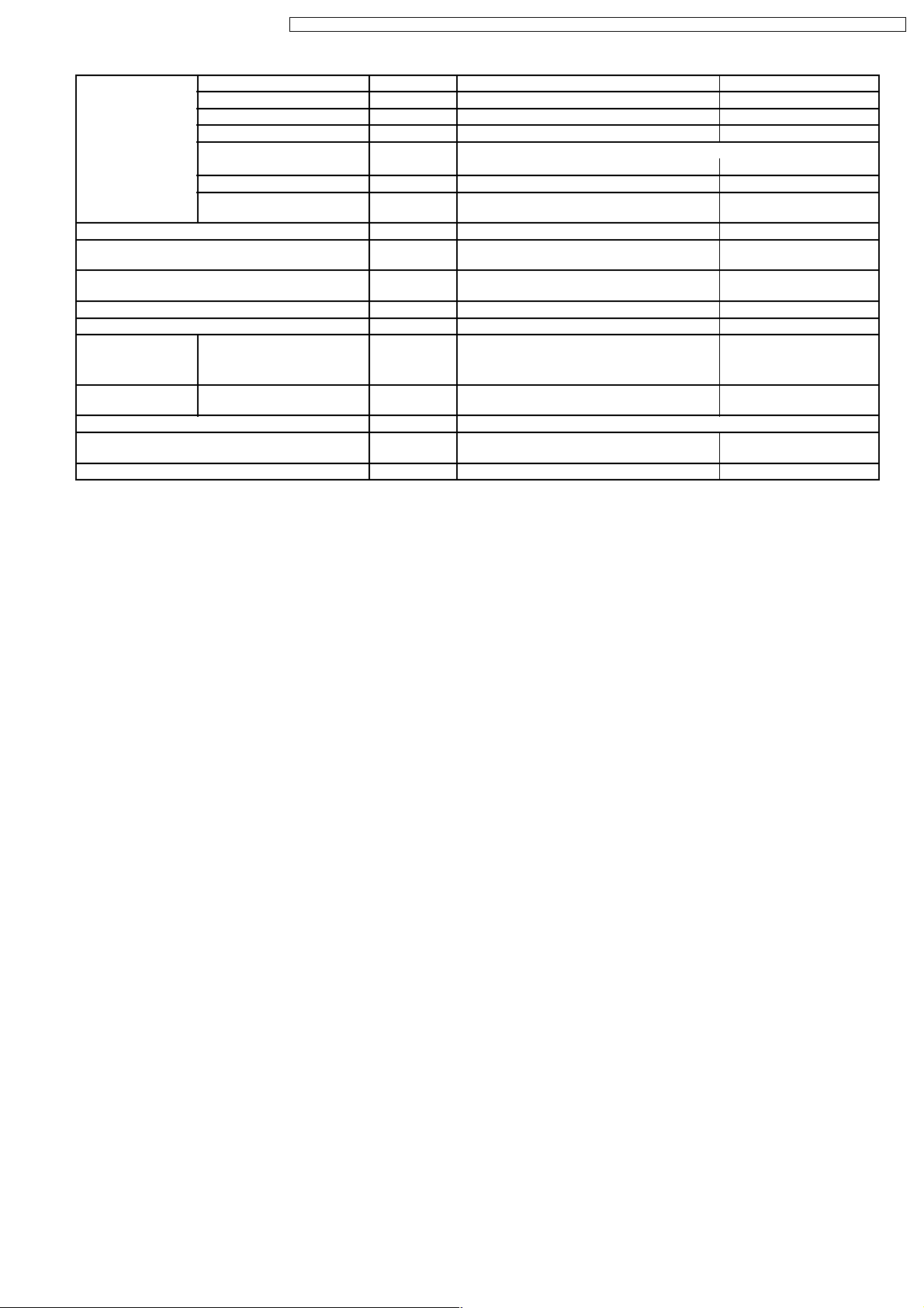
Heat Exchanger Description Evaporator Condenser
Tube material Copper Copper
Fin material Aluminium Aluminium
Fin Type Slit Fin Louver Fin
Row / Stage (Plate fin configuration, forced draft)
(A) 2 × 15 (B) 2 × 15 2 × 24
FPI 21 19 16
Size (W × H × L) mm 610 × 315 × 25.4 756
Refrigerant Control Device — Capillary Tube
Refrigeration Oil (c.c) — SUNISO 4GDID or ATMOS
Refrigerant (R-22) g (oz) — (A) 840 (29.7)
Thermostat Electronic Control —
Protection Device — Overload Protector
Capillary Tube Length mm — (A) 610 (B) 920
Flow Rate l/min — (A) 16.5 (B) 9.5
Inner Diameter mm — (A) 1.7 (B) 1.5
Air Filter Material
Style
Capacity Control Capillary Tube
Compressor Capacitor µF, VAC — (A) 30 µF, 370 VAC
Fan Motor Capacitor µF, VAC 1.5 µF, 400 VAC 3.0 µF, 450 VAC
(c.c) P.P.
Honeycomb
× 609.6 × 44
719.5
M60 (290, 410)
(B) 820 (28.9)
—
(B) 1 5 µF, 440 VAC
•
Specifications are subject to change without notice for further improvement.
13
Page 14
CS-C9BKPG CU-2C14BKP5G / CS-C9BKPG CU-2C18BKP5G / CS-C9BKPG CU-3C20BKP5G / CS-C7BKPG CU-2C19BKP5G / CS-C12BKPG
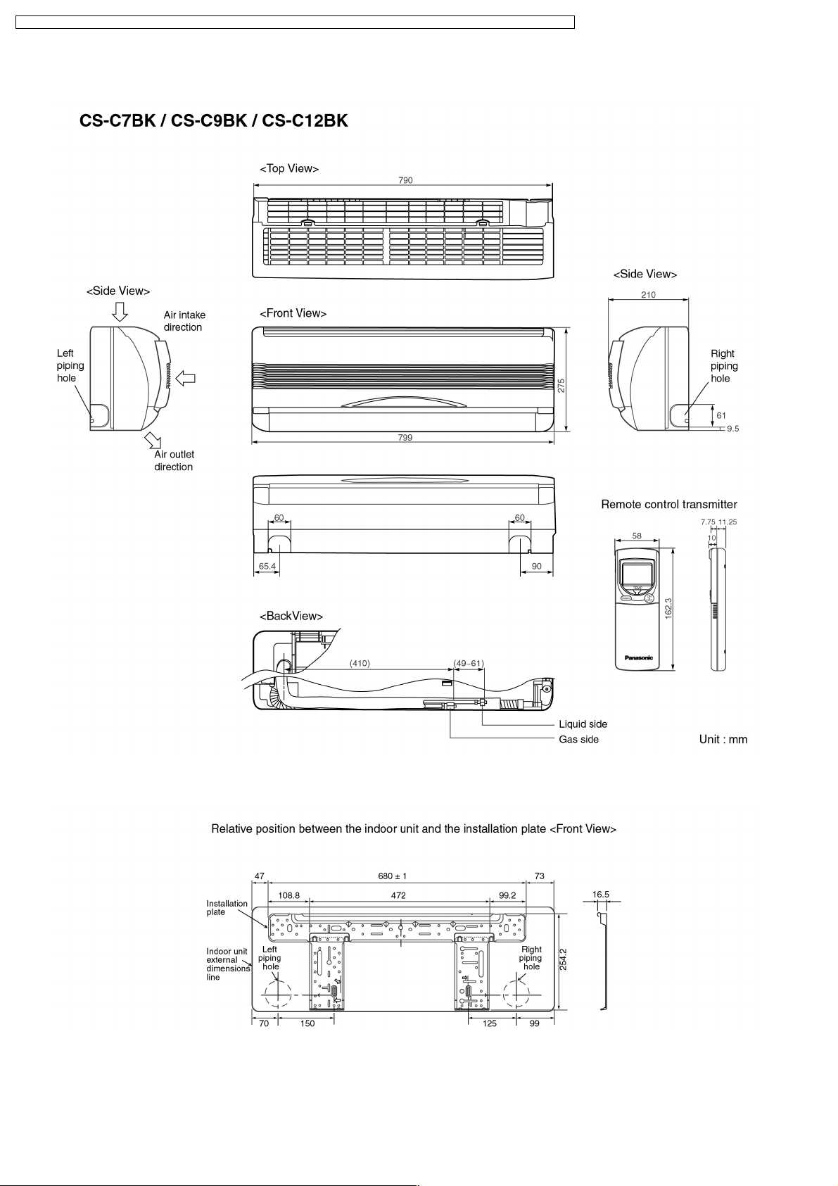
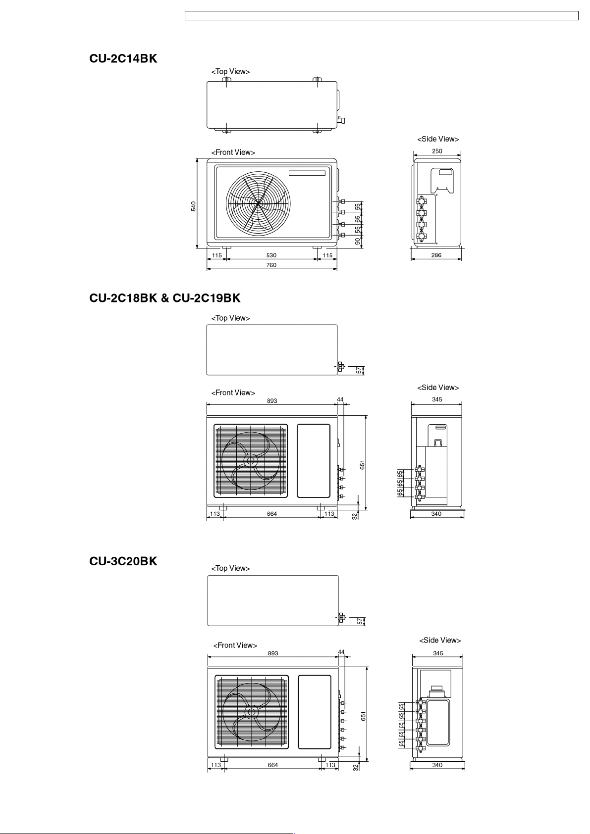
4 Dimensions
14
Page 15
CS-C9BKPG CU-2C14BKP5G / CS-C9BKPG CU-2C18BKP5G / CS-C9BKPG CU-3C20BKP5G / CS-C7BKPG CU-2C19BKP5G / CS-C12BKPG
15
Page 16
CS-C9BKPG CU-2C14BKP5G / CS-C9BKPG CU-2C18BKP5G / CS-C9BKPG CU-3C20BKP5G / CS-C7BKPG CU-2C19BKP5G / CS-C12BKPG
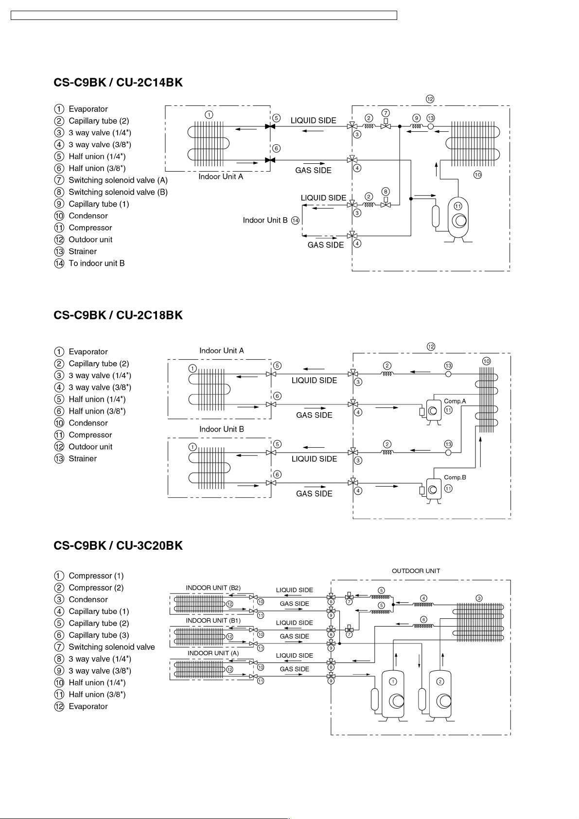
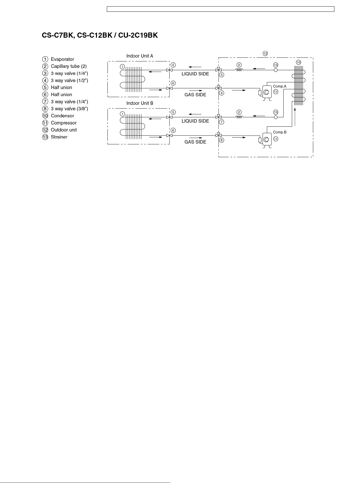
5 Refrigeration Cycle Diagram
16
Page 17
CS-C9BKPG CU-2C14BKP5G / CS-C9BKPG CU-2C18BKP5G / CS-C9BKPG CU-3C20BKP5G / CS-C7BKPG CU-2C19BKP5G / CS-C12BKPG
17
Page 18
CS-C9BKPG CU-2C14BKP5G / CS-C9BKPG CU-2C18BKP5G / CS-C9BKPG CU-3C20BKP5G / CS-C7BKPG CU-2C19BKP5G / CS-C12BKPG
6 Block Diagram
18
Page 19
CS-C9BKPG CU-2C14BKP5G / CS-C9BKPG CU-2C18BKP5G / CS-C9BKPG CU-3C20BKP5G / CS-C7BKPG CU-2C19BKP5G / CS-C12BKPG
19
Page 20
CS-C9BKPG CU-2C14BKP5G / CS-C9BKPG CU-2C18BKP5G / CS-C9BKPG CU-3C20BKP5G / CS-C7BKPG CU-2C19BKP5G / CS-C12BKPG
20
Page 21
CS-C9BKPG CU-2C14BKP5G / CS-C9BKPG CU-2C18BKP5G / CS-C9BKPG CU-3C20BKP5G / CS-C7BKPG CU-2C19BKP5G / CS-C12BKPG
21
Page 22
CS-C9BKPG CU-2C14BKP5G / CS-C9BKPG CU-2C18BKP5G / CS-C9BKPG CU-3C20BKP5G / CS-C7BKPG CU-2C19BKP5G / CS-C12BKPG
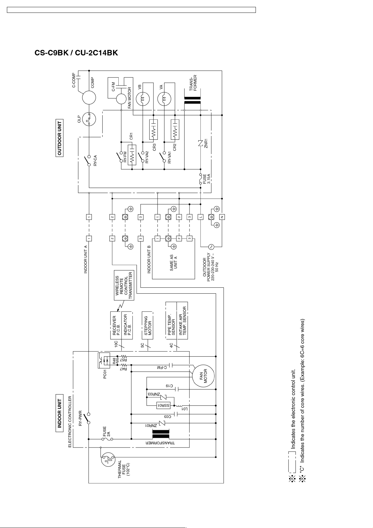
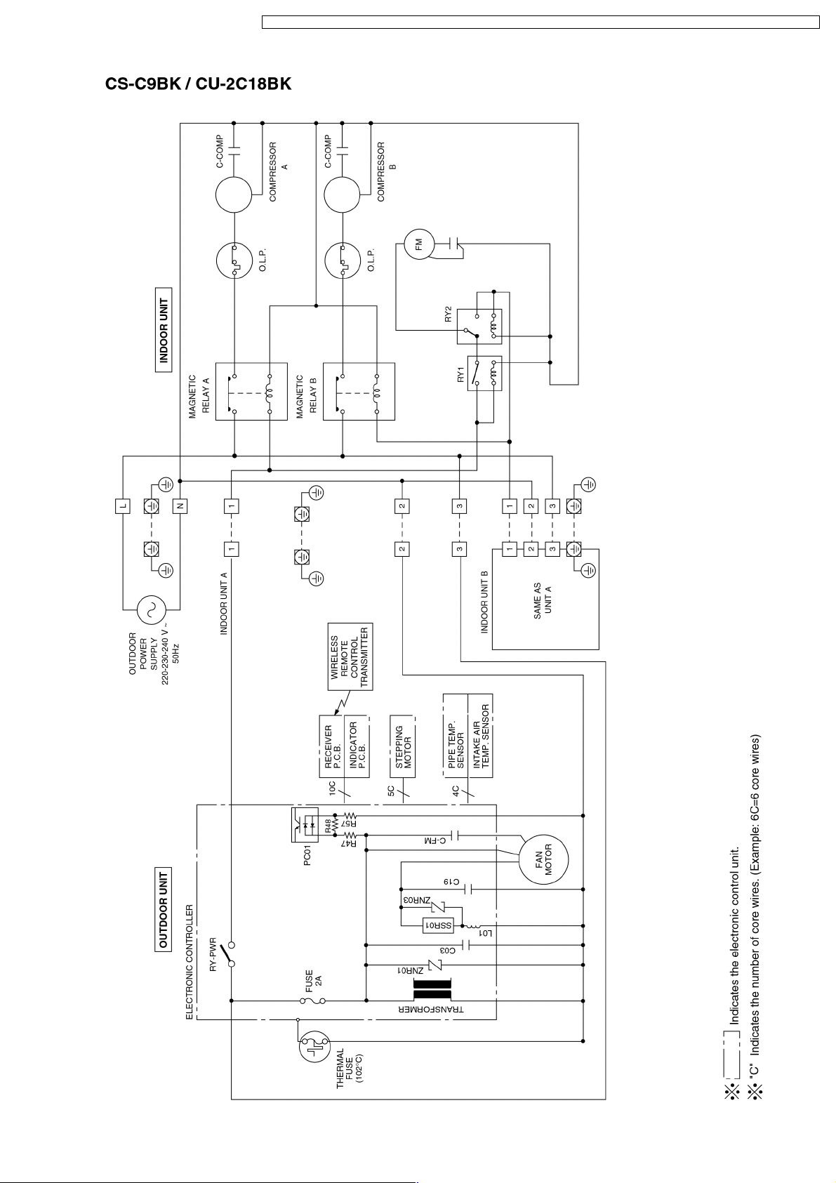
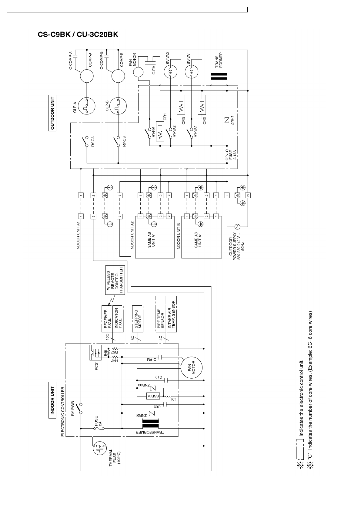
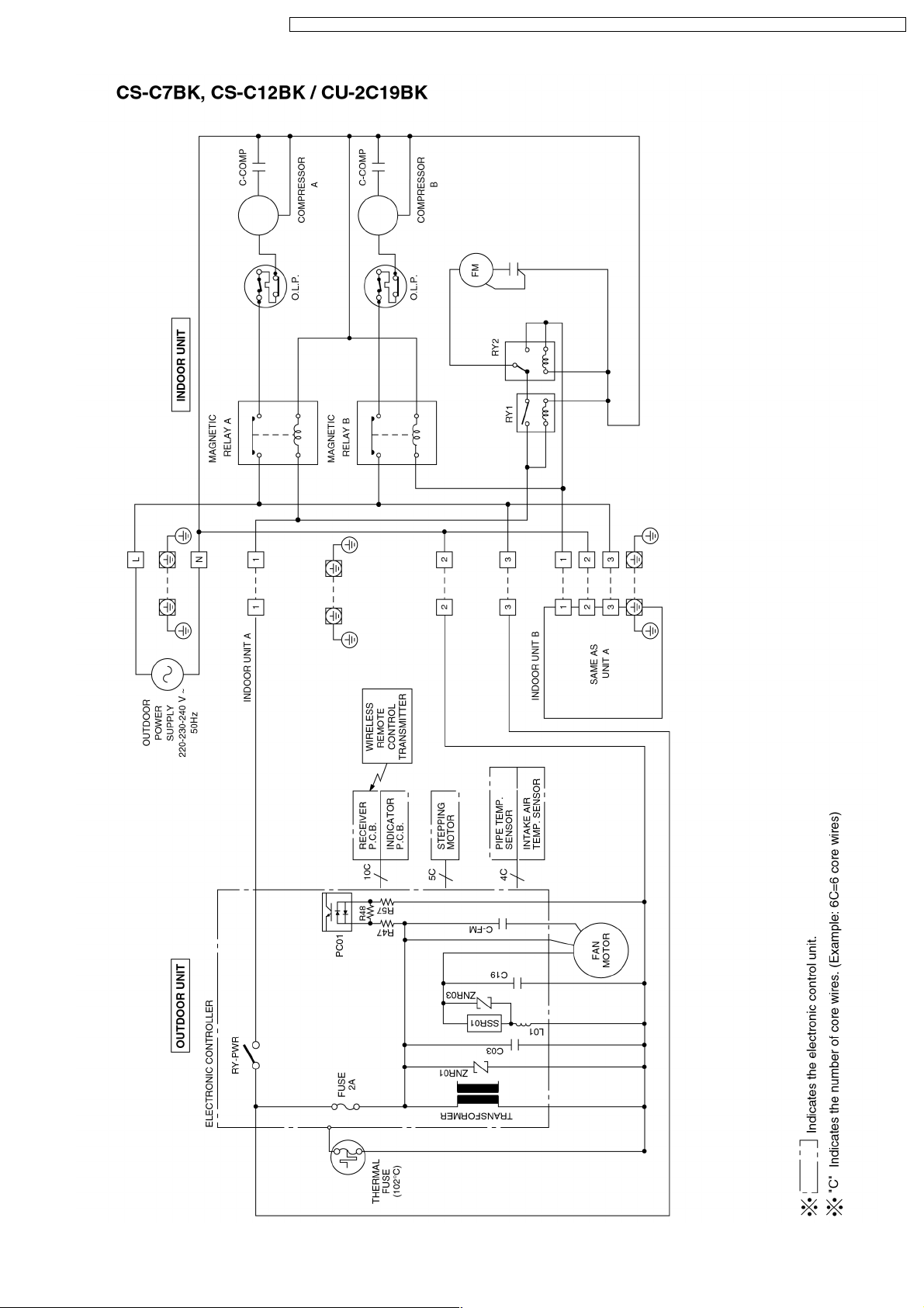
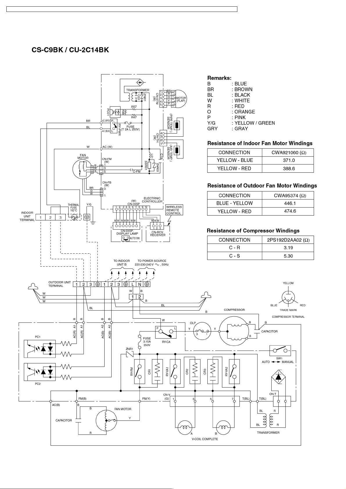
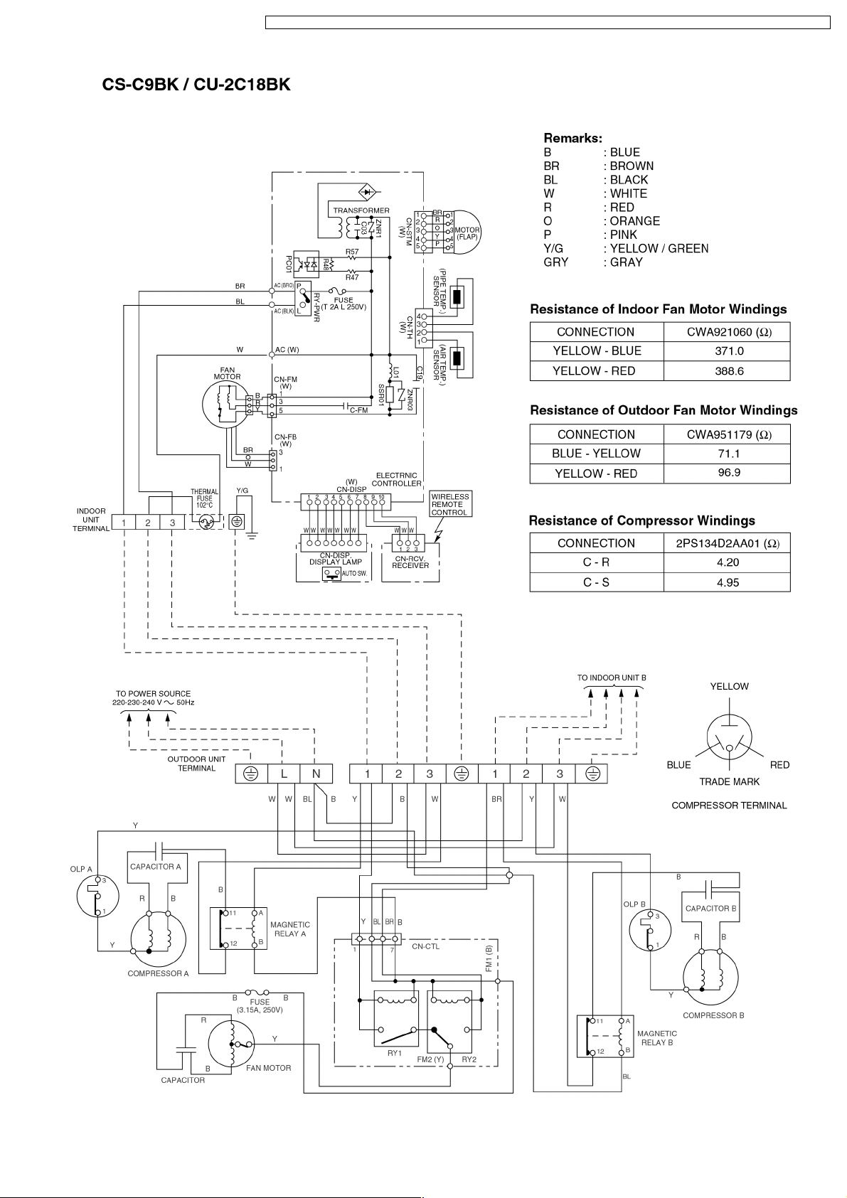
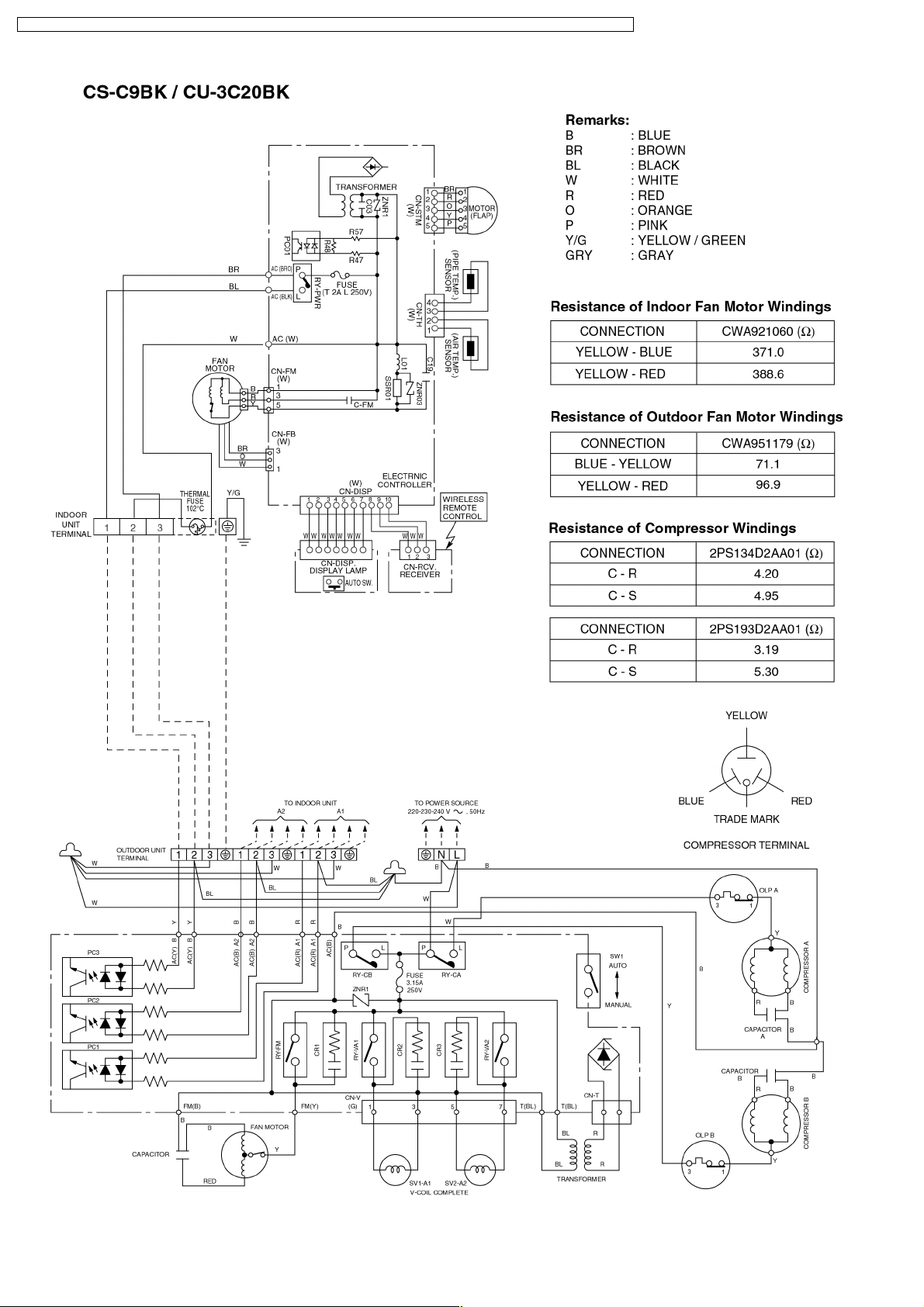
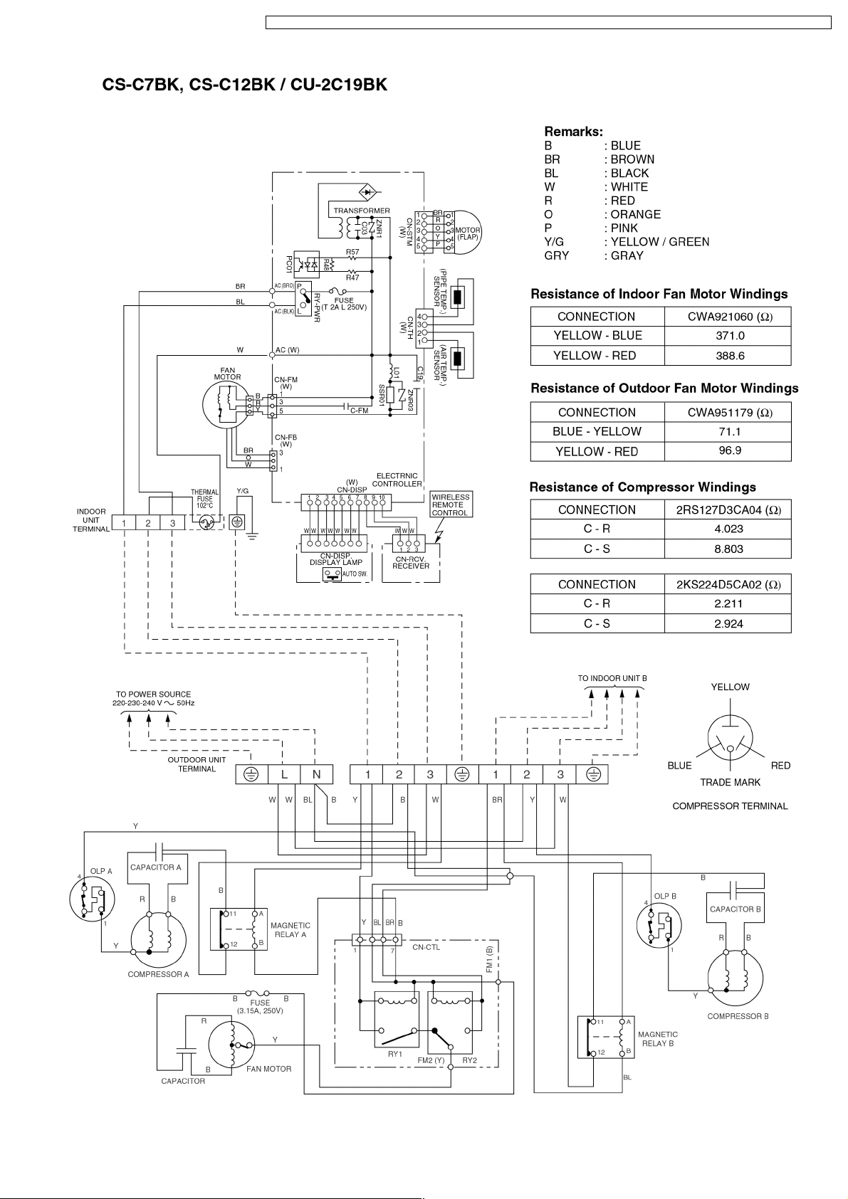
7 Wiring Diagram
22
Page 23
CS-C9BKPG CU-2C14BKP5G / CS-C9BKPG CU-2C18BKP5G / CS-C9BKPG CU-3C20BKP5G / CS-C7BKPG CU-2C19BKP5G / CS-C12BKPG
23
Page 24
CS-C9BKPG CU-2C14BKP5G / CS-C9BKPG CU-2C18BKP5G / CS-C9BKPG CU-3C20BKP5G / CS-C7BKPG CU-2C19BKP5G / CS-C12BKPG
24
Page 25
CS-C9BKPG CU-2C14BKP5G / CS-C9BKPG CU-2C18BKP5G / CS-C9BKPG CU-3C20BKP5G / CS-C7BKPG CU-2C19BKP5G / CS-C12BKPG
25
Page 26
CS-C9BKPG CU-2C14BKP5G / CS-C9BKPG CU-2C18BKP5G / CS-C9BKPG CU-3C20BKP5G / CS-C7BKPG CU-2C19BKP5G / CS-C12BKPG
8 Operation Details
8.1. Cooling Mode Operation
Cooling in operation according to Remote Control setting.
Time Delay Safety Control (3 minutes)
When the compressor is stopped by Remote Control, it restarts after 3 minutes when the Remote Control is turned ON.
•
When the setting temperature is reached during cooling operation, the compressor stops and it will not start for 3 minutes.
•
7 minutes Time Save Control
The compressor will start automatically if it has stopped for 7 minutes even if the room temperature is between the compressor
•
ON temperature and OFF temperature.
Starting Current Control
When the compressor outdoor fan motor and indoor fan motor are simultaneously started, the indoor fan motor will operate 1.6
•
second later.
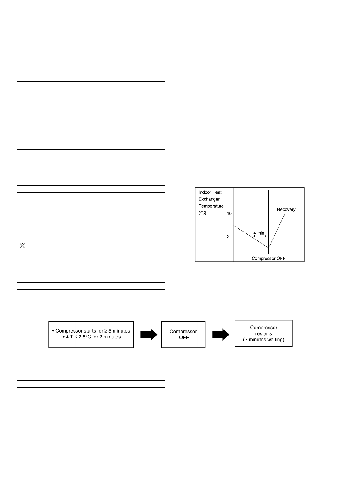
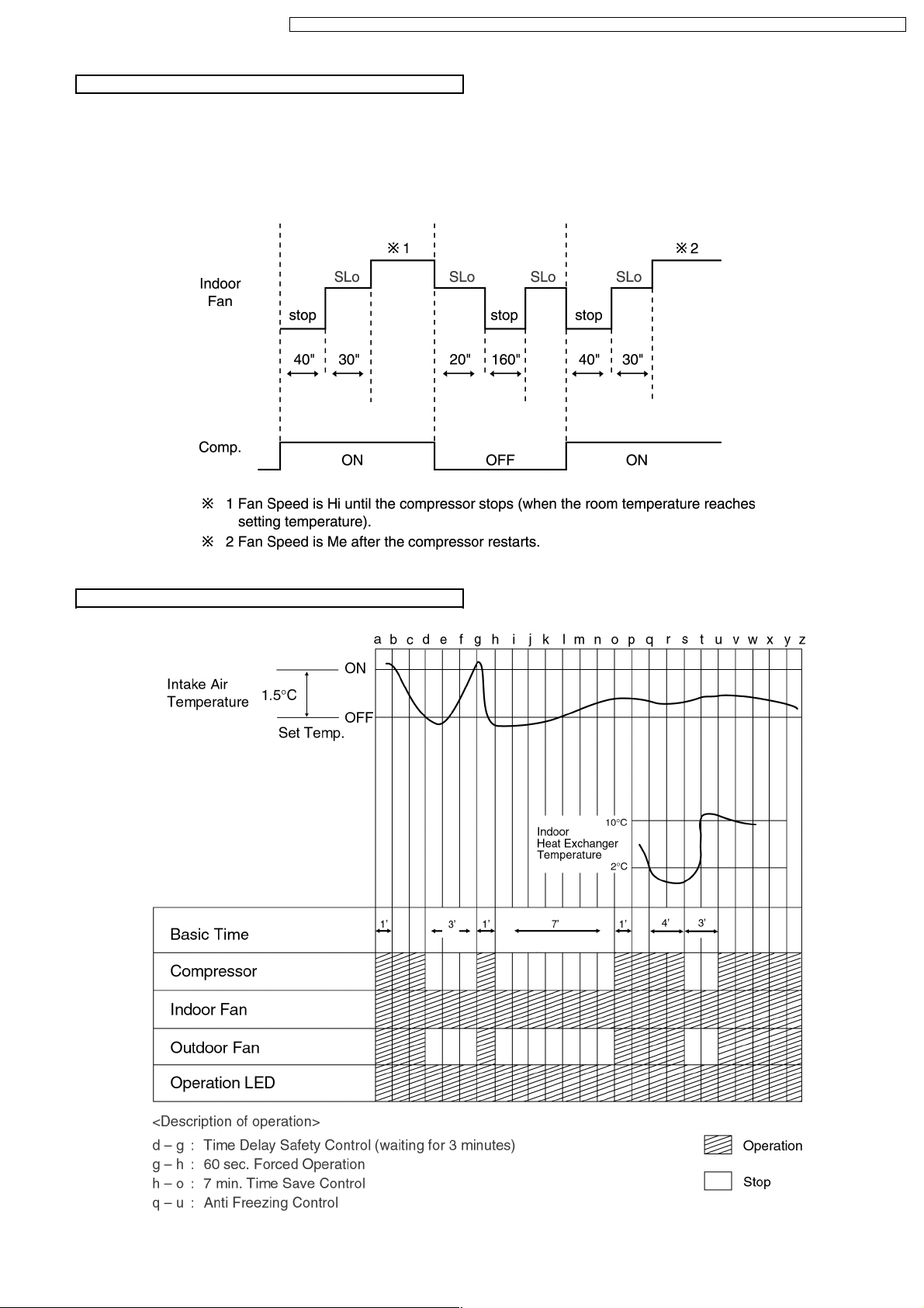
Anti-Freezing Control
If the temperature of the indoor heat exchanger falls
•
continuously below 2°C for 4 minutes or more, the
compressor turns off to protect the indoor heat exchanger
from freezing. The fan speed setting remains the same.
Compressor will restart again when the indoor heat
•
exchanger temperature rises to 10°C (Recovery).
3 minutes waiting of Time Delay Safety Control is valid for
Cooling Operation.
Compressor Reverse Rotation Protection Control
If the compressor is operating continuously for 5 minutes or longer and the temperature difference between intake air and
•
indoor heat exchanger is 2.5°C or less for 2 minutes, compressor will stop and restart automatically.
(Time Delay Safety Control is valid)
▲
T = Intake air temperature - Indoor heat exchanger temperature
This is to protect reverse rotation of the compressor when there is a instantaneous power failure.
Anti-Dew Formation Control
Purpose is to prevent dew formation on indoor unit air discharge area.
•
When the following conditions accur for 30 minutes continuously, anti-dew formation is controlled by indoor fan speed shift to
•
low (CLo to HLo):
Indoor intake air temperature is more than 24°C and less than 30°C.
−
Remote Contro l setting temperature is less than 25°C.
−
Compressor is on.
−
Cooling operation mode.
−
Indoor Fan motor operate at Low fan speed.
−
This control is cancelled immediately when above condition is changed.
•
26
Page 27
CS-C9BKPG CU-2C14BKP5G / CS-C9BKPG CU-2C18BKP5G / CS-C9BKPG CU-3C20BKP5G / CS-C7BKPG CU-2C19BKP5G / CS-C12BKPG
Automatic Fan Speed Mode
When Automatic Fan Speed is selected at Remote Control during cooling operation.
Fan speed rotates in the range of Hi to Me.
•
Deodorizing Control.
•
Cooling Operation Time Diagram
27
Page 28
CS-C9BKPG CU-2C14BKP5G / CS-C9BKPG CU-2C18BKP5G / CS-C9BKPG CU-3C20BKP5G / CS-C7BKPG CU-2C19BKP5G / CS-C12BKPG
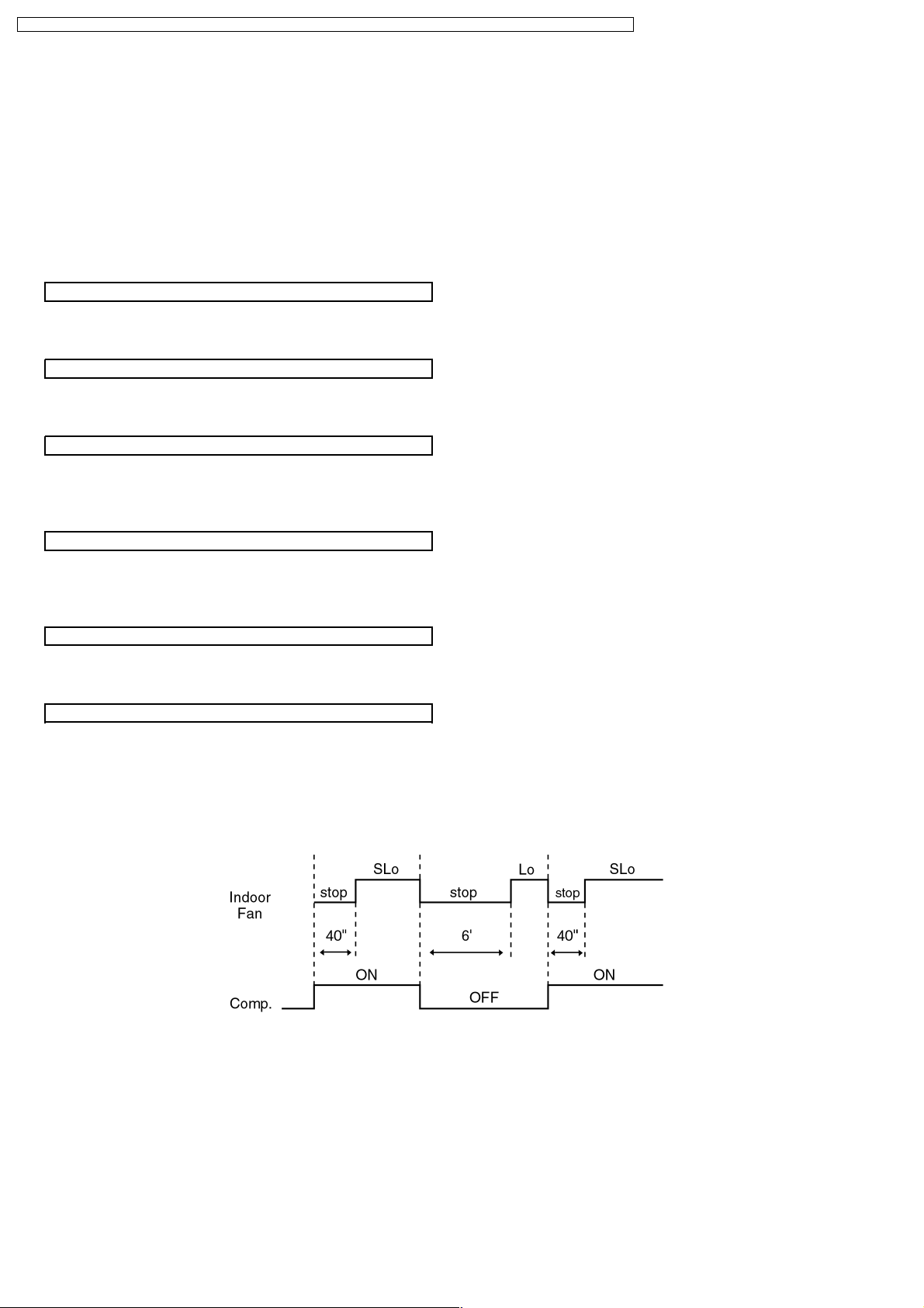
8.2. Soft Dry Mode Operation
The unit starts cooling operation until the room temperature reaches the setting temperature set on the Remote Control, and
•
then Soft Dry operation will start.
During Soft Dry operation, the Indoor Fan will operate at SLo speed.
•
The operation will be switched on and off for up to 10 minutes “ON” and 6 minutes “OFF”. Once Soft Dry operation is turned
•
off, it stops for 6 minutes.
Time Delay Safety Control
Once the compressor stops, it will not start for 3 minutes during Cooling operation.
•
Starting Current Control
Same as Starting Current Control for Cooling Mode operation.
•
Anti-Freezing Control
Same as Anti-Freezing Control for Cooling Mode operation. (For Soft Dry region, 6 minutes waiting is valid during compressor
•
stops.)
Compressor Reverse Rotation Protection Control
Same as Compressor Reverse Rotation Protection Control for Cooling Mode Operation. (For Soft Dry region, 6 minutes waiting
•
is valid during compressor stops.)
Anti-Dew Formation Control
Same as Anti-Dew Formation Control for Cooling Mode operation.
•
Automatic Fan Speed Mode
When Automatic Fan Speed is selected at Remote Control during Soft Dry operation.
Fan speed off and on at SLo speed.
•
Deodorizing Control.
•
28
Page 29

CS-C9BKPG CU-2C14BKP5G / CS-C9BKPG CU-2C18BKP5G / CS-C9BKPG CU-3C20BKP5G / CS-C7BKPG CU-2C19BKP5G / CS-C12BKPG
Soft Dry Operation Time Diagram
29
Page 30

CS-C9BKPG CU-2C14BKP5G / CS-C9BKPG CU-2C18BKP5G / CS-C9BKPG CU-3C20BKP5G / CS-C7BKPG CU-2C19BKP5G / CS-C12BKPG
8.3. Air Circulation Mode Operation
When the temperature near the ceiling reaches the setting temperature, Air Circulation Mode operation commences at low
•
airflow volume. It stops when the temperature drops to 2°C below the setting temperature.
Air Circulation Mode Operation Time Diagram
8.4. Automatic Mode Operation
Standard for Determining Operation Mode
Indoor fan operates at SLo fan speed for 25 seconds.
•
After judging indoor air temperature, the operation mode is determined and operation continued at the mode determined.
•
After the operation mode has been determined, the mode does not change. However, Soft Dry mode operation includes
•
Cooling mode operation.
Room temperature adjustment.
•
The following are added to the setting temperature specified as above.
The mode judging temperature and standard setting temperature can be increased by 2°C, by open the circuit of JX1 at indoor
•
electronic controller.
30
Page 31

CS-C9BKPG CU-2C14BKP5G / CS-C9BKPG CU-2C18BKP5G / CS-C9BKPG CU-3C20BKP5G / CS-C7BKPG CU-2C19BKP5G / CS-C12BKPG
8.5. Sleep Mode Auto Operation
Cooling or Soft Dry Operation
Purpose is to obtain a comfortable room temperature while
sleeping. When you press the SLEEP Mode, the following
movement will start to avoid overcooling.
Sleep shift operation starts, when the room temperature
•
reaches the setting temperature or after 1 hour of operation.
The setting temperature will be risen by 0.5°C at the start of
•
operation and by 0.5°C one hour later.
The airflow volume will automatically change to Lo fan
•
speed.
Sleep Mode operation time is 8 hours, the operation will be
•
stop after 8 hours.
When used together with the Timer, the Timer has priority.
•
8.6. Powerful Mode Operation
Purpose of this operation is to obtain the setting temperature quickly.
•
When the Powerful Mode is set, the set temperature will be automatically decreased 3°C against the present setting
•
temperature (Lower temperature: 16°C).
This operation automatically will be running under SHi Fan Speed (Cooling), SLo Fan Speed (Soft Dry).
•
Vertical Airflow Direction:-
•
-In“Manual” setting, the vane will automatically swing down 10° lower than previous setting.
-In“Auto” setting, the vane will automatically swing up and down. However the lower limit will be shifted 10° downward.
Powerful Mode will operate for 15 minutes only, after that it will shift back to previous operation mode.
•
Powerful Mode will stop if:-
•
- Powerful mode button is pressed again.
- Stopped by ON / OFF switch.
- Timer OFF activates.
- Economy mode button is pressed.
- Sleep mode is pressed.
- Operation mode button is changed.
8.7. Economy Mode Operation
Purpose of this operation is to save or reduced electrical power consumption of the room air conditioner.
•
When the Economy Mode is set, the set temperature will be automatically increased 0.5°C against the preset setting
•
temperature (Higher temperature: 30°C).
This operation automatically will be running under SLo Fan Speed.
•
Vertical Airflow Direction:-
•
In “Manual” or “Auto” setting, the vane will automatically change to Auto Air Swing.
Economy Mode will stop if:-
•
- Economy Mode button is pressed again.
- Stopped by ON / OFF switch.
- Timer OFF activates.
- Powerful mode button is pressed.
- Auto or Manual air swing button is pressed.
- Fan Speed control button is pressed.
- Sleep Mode button is pressed ON.
- Operation Mode is changed.
31
Page 32

CS-C9BKPG CU-2C14BKP5G / CS-C9BKPG CU-2C18BKP5G / CS-C9BKPG CU-3C20BKP5G / CS-C7BKPG CU-2C19BKP5G / CS-C12BKPG
8.8. Random Auto Restart Control
If there is a power failure, operation will be automatically restarted after 3 to 4 minutes when the power is resumed.
•
It will start with previous operation mode and airflow direction.
Restart time is decided randomly using 4 parameter:-
•
Intake air temperature, setting temperature, fan speed and Air Swing Blade position.
Auto Restart Control is not available when Timer or Sleep Mode is set.
•
This control can be omitted by open the circuit of JX2. (Refer Circuit Diagram)
•
8.9. Indoor Fan Speed Control
Auto Fan Speed Control
•
When set to Auto Fan Speed, the fan speed is adjusted between maximum and minimum setting as shown in the table.
Manual Fan Speed Control
•
Basic fan speed adjustment (3 settings, from Lo to Hi) can be carried out by using the Fan Speed selection button at the remote
control.
32
Page 33

CS-C9BKPG CU-2C14BKP5G / CS-C9BKPG CU-2C18BKP5G / CS-C9BKPG CU-3C20BKP5G / CS-C7BKPG CU-2C19BKP5G / CS-C12BKPG
8.10. Vertical Airflow Direction Control
Vertical Airflow Direction Auto-Control
When set a Airflow Direction Auto-Control with remote
•
control, the louver swings up and down as shown in the
diagram.
The louver does not swing when the Indoor Fan Motor
•
stops during operation at the upper limit.
When stopped with remote control, the discharge vent is
•
reset, and stopped at the closing position.
1. There is no swinging while indoor fan motor is stopped during Cooling and Soft Dry operation.
2. In Air Circulation operation, when the intake air temperature reaches set temperature, the airflow direction is changed from upper limit to
lower limit. When the intake air temperature falls to 2°C lower than set temperature, the airflow direction is changed from lower limit to
upper limit.
Vertical Airflow Direction manual Control
When the manual Airflow Direction Selection Button is
•
pressed, the automatic airflow is released and the airflow
direction louver move up and down in the range shown in
the diagram.
The louver can be adjusted by pressing the button to the
desired louver position.
When the remote control is used to stop the operation, the
•
discharge vent is reset, and stopped at the closing position.
8.11. Delay ON Timer Control
When the Delayed ON Timer is set by using the remote control, the unit will start operate slightly before the set time, so that
•
the room will reach nearly to the set temperature by the desired time.
For Cooling and Soft Dry mode, the operation will start 15 minutes before the set time.
•
For Automatic mode, the indoor fan will operate at SLo speed for 25 seconds, 15 minutes before the set time to detect the
•
intake air temperature to determine the operation mode. The operation indication lamp will blink at this time.
8.12. Remote Control Signal Receiving Sound
Long beep sound will be heard when:-
•
Stopping the Air Conditioner using ON/OFF switch.
−
Stopping the Sleep Mode.
−
Stopping the Powerful Mode.
−
Stopping the Economy Mode.
−
Short beep sound will be heard for others.
•
To switch off the beep sound:-
•
Press the “Automatic Operation Button” continuously for 10 seconds or more (“beep”“beep” will be heard at the 10th second).
Repeat the above if you want to switch ON the beep sound.
However, if the “Automatic Operation Button” has been pressed the Automatic operation will be activated.
If you do not require this operation, you may change it by using the remote control.
33
Page 34

UT
AN
UT
UT
DR
AN
COOL
CS-C9BKPG CU-2C14BKP5G / CS-C9BKPG CU-2C18BKP5G / CS-C9BKPG CU-3C20BKP5G / CS-C7BKPG CU-2C19BKP5G / CS-C12BKPG
9 Operating Instructions
SAFETY PRECAUTIONS
Before operating, please read the following
“Safety Precautions” carefully.
● To prevent personal injury, injury to others and
property damage, the following instructions must be
followed.
● Incorrect operation due to failure to follow instructions
will cause harm or damage, the seriousness of which
is classified as follow:
!
This sign warns of death or serious injury.
This sign warns of damage to property.
● The instructions to be followed are classified by the
following symbols:
This symbol (with a white background) denotes an
These symbols (with a black background) denote
Warning
!
Caution
action that is PROHIBITED.
F
F
O
actions that are COMPULSORY.
■ Installation Precautions
!
Warning
● Do not install, remove and reinstall the unit by
yourself.
Improper installation will cause leakage, electric
shock or fire. Please engage an authorized dealer
or specialist for the installation work.
!
Caution
● This room air conditioner must be
earthed.
Improper grounding could cause
electric shock.
● Ensure that the drainage piping is
connected properly.
Otherwise, water will leak out.
● Do not install the unit in a
potentially explosive atmosphere.
Gas leak near the unit could cause
fire.
■ Operation Precautions
!
This sign warns of death or serious injury.
● Do not share outlet.
● Do not operate with wet hands.
● Do not damage or modify the power cord.
● Do not insert finger or other objects into the
● Do not expose directly to cold air for a long
● Use specified power cord.
F
F
O
● If abnormal condition (burnt smell, etc.)
● Do not wash the unit with water.
● Do not use for other purposes such as
● Do not use any combustible equipment at
● Do not sit or place anything on the outdoor
● Switch off the power supply before cleaning.
● Ventilate the room regularly.
● Pay attention as to whether the installation
F
F
O
● Switch off the power supply if the unit is not
Warning
indoor or outdoor units.
period.
occurs, switch off the power supply.
!
Caution
This sign warns of injury.
preservation.
airflow direction.
unit.
rack is damaged after long period of usage.
used for a long period.
NAME OF EACH PART
■ Indoor Unit
1 Front Panel
2 Air Intake Vent
3 Air Outlet Vent
4 Vertical Airflow Direction Louver
5 Horizontal Airflow Direction Louver
(manually adjusted)
6 Indicator Panel
123 654
1 Auto Operation Button
(when the front panel is opened)
2 Economy Mode Indicator – GREEN
3 Powerful Mode Indicator – ORANGE
4 Power Indicator – GREEN
5 Sleep Mode Indicator – ORANGE
6 Timer Mode Indicator – ORANGE
1
2
POWERFULPOWERFULECONOMYECONOMY POWERPOWER
POWERFULPOWERFULECONOMYECONOMY POWERPOWER
3465
SLEEPSLEEP
SLEEPSLEEP
● Indoor Unit
(when the front panel is opened)
1
3
2
1 Front Panel 2 Air Filters 3 Air Purifying Filter
■ Accessories
● Remote Control
M
O
D
A
I
R
S
S
t
e
p
1
O
N
O
2
F
F
C
H
E
T
C
I
K
M
R
E
E
R
S
E
T
C
A
C
N
L
O
C
K
+
B
A
T
T
E
R
Y
● Remote Control Indication Sticker
AU
T
O
C
O
O
N
O
L
O
AU
D
F
F
T
R
O
YFA
N
AU
P
O
FA
T
T
W
O
E
N
E
R
M
F
U
P
L
E
O
F
E
F
C
/
O
O
N
N
W
O
I
M
N
Y
G
S
L
E
E
P
F
A
N
S
P
E
E
D
3
S
E
T
C
E
L
■ Outdoor Unit
CU-2C18BKP5G
CU-2C19BKP5G
1
TIMERTIMER
TIMERTIMER
7
CU-2C14BKP5G CU-3C20BKP5G
1 Air Intake Vents
2 Ground Terminal
(Inside cover)
3 Power Supply Cord
4 Piping
2
5 Drain Hose
6 Connecting Cable
7 Air Outlet Vents
3
4
5
● Remote Control Holder
6
● Two RO3 (AAA) dry-cell batteries or equivalent
● Air Purifying Filter
(Catechin Air
Purifying Filter)
(Solar Refreshing
Deodorizing Filter)
34
Page 35

CHECK
TEMP
AUTO
ON
OFF
FAN
AUTO
RESET CLOCK
MODE
SLEEP
ECONOMY
FAN SPEED
AIR SWING
OFF
CANCEL
ON
SET
1
2
3
TIMER
OFF/ON
POWERFUL
AUTO
MANUAL
#
!
$
%
^
$
*
&
3
5
8
7
9
0
6
4
(
AN
COOL
C
H
E
C
K
AUTO
O
F
AUTOHEAT
DRY
FANCOOL
FAN
AUTO
AUTO
R
E
S
E
T
C
L
O
C
K
A
I
R
S
W
I
N
G
O
F
F
C
A
N
C
E
L
1
2
3
T
IM
E
R
P
O
W
E
R
F
U
L
A
U
T
O
M
A
N
U
A
L
E
C
O
N
O
M
Y
S
L
E
O
N
S
E
T
F
A
N
S
P
E
E
D
M
O
D
E
2
1
1
.5
V
1
.5
V
CHECK
AUTO
AUTO HEAT DRYFANCOOL
FAN
AUTO
RESET CLOCK
FAN SPEED
AIR SWING
OFF
CANCEL
ON
SET
1
2
3
TIMER
AUTO
MANUAL
1
2
O
F
F
O
N
H
E
A
HEAT
DRDRY
FA
N
ANC
O
O
L
COOL
C
H
E
C
K
T
E
M
P
AU
T
UTO
AU
T
UTO
FA
N
AN
AU
T
UTO
R
E
S
E
T
C
L
O
C
K
A
IR
S
W
IN
G
O
F
F
C
A
N
C
E
L
1
2
3
T
I
M
E
R
O
F
F
/
O
N
P
O
W
E
R
F
U
L
A
U
T
O
M
A
N
U
A
L
E
C
O
N
O
M
Y
S
LE
E
P
O
N
SE
T
F
A
N
S
P
E
E
D
M
O
D
E
CS-C9BKPG CU-2C14BKP5G / CS-C9BKPG CU-2C18BKP5G / CS-C9BKPG CU-3C20BKP5G / CS-C7BKPG CU-2C19BKP5G / CS-C12BKPG
NAME OF EACH PART
■ Remote Control
1
2
AUTUTO DRDRYFAN
COOL
● Remote Control Signal.
• Make sure it is not obstructed.
• Maximum distance : 10 m.
• Signal received sound.
One short beep or one long beep.
● Notes for Remote Control.
• Do not throw or drop.
• Do not get it wet.
• Certain type of fluorescent lamps may affect
signal reception. Consult your dealer.
1 Signal Transmitter
2 Operation Display
3 Powerful Mode Operation Button
4 Room Temperature Setting Button
(self-illuminating button)
5 Operation Mode Selection Button
6 Economy Mode Operation Button
7 Auto Airflow Direction Button
8 ON-Timer Button
9 OFF-Timer Button
0 Reset Point
(Press with fine-tipped object to clear the memory)
! OFF/ON Button
(self-illuminating button)
@ Sleep Mode Operation Button
# Fan Speed Selection Button
$ Manual Airflow Direction Selection Button
% Timer Set Button
^ Timer Cancellation Button
& Time-Setting Button
* Clock Button
( Remote Control Cover
● How to Insert the Batteries
1
Slide down the remote control cover completely
2
Insert the batteries
– Be sure the direction is correct
– 12.00 at display - flashing
• Set the current time (CLOCK) immediately to
prevent battery exhaustion.
● About the batteries
• Can be used for approximately one year.
● Observe the following when replacing the
batteries
• Replace with new batteries of the same type.
• Do not use rechargeable batteries (Ni-Cd).
• Remove the batteries if the unit is not going to be
used for a long period.
PREPARATION BEFORE OPERATION
■ Indoor Unit
1
Knife switch
HOW T O OPERA TE
2
3
5
1
Set the knife switch to “ON”
2
6
3
5
4
2
Open the front panel
3
Remove the air filters
4
Fit the air purifying filters in place
5
Insert the air filters
6
Close the front panel
■ Remote Control
– To set the current time
1
Press 1.
2
Then press 2 to increase or decrease the time.
3
Press 1 again.
Set time at display will light up.
■ To start the operation
• Press 1.
• POWER indicator (green) on the indoor unit will light
up.
• To stop, press once more.
■ Setting Mode
• Press 2 to select:-
AUTO – Automatic Operation
COOL – Cooling Operation
DRY – Soft Dry Operation
FAN – Air Circulation Operation
35
1
6
4
■ Setting Temperature
• Press 3 to increase or decrease the temperature.
• The temperature can be set between 16°C ~ 30°C.
• Recommended temperature:
COOL 26°C ~ 28°C
1°C ~ 2°C
DRY lower than the
room temperature
• During AUTO Operation, press 3 to select:-
• Operation with 2°C higher than the standard
temperature.
• Operation with the standard temperature.
• Operation with 2°C lower than the standard
temperature.
● Standard Temperature
Indoor
temperature
23°C
• Once the Automatic Operation is selected, the indoor
temperature sensor operates automatically to select
the desired operation mode with Cooling or Soft Dry.
• After the operation mode has been selected, the
mode does not change.
Operation
Cooling
Soft Dry
Standard
temperature
25°C
22°C
Page 36

AUTO
AUTO HEAT DRY FANCOOL
FAN
AUTO
MODE
SLEEP
ECONOMY
FAN SPEED
AIR SWING
OFF
CANCEL
ON
SET
1
2
3
TIMER
OFF/ON
POWERFUL
AUTO
MANUAL
3
6
4
1
7
5
2
CS-C9BKPG CU-2C14BKP5G / CS-C9BKPG CU-2C18BKP5G / CS-C9BKPG CU-3C20BKP5G / CS-C7BKPG CU-2C19BKP5G / CS-C12BKPG
■ Setting the Fan Speed
• Press 4 to select:-
FAN – Low Fan Speed
FAN – Medium Fan Speed
FAN – High Fan Speed
AUTO
FAN – Automatic Fan Speed
The speed of the indoor fan is adjusted
automatically according to the operation.
The indoor fan stops occasionally during
cooling operation.
■ Setting the Vertical Airflow Direction
• Press 5 or 6 to select:-
COOL / DRY Operation
AUTO
36° 61°
Swing up/down
Automatically
MANUAL
Five stages of adjustment
can be made between
14° ~ 36°.
FAN Operation
AUTO
Swing up/down
Automatically
MANUAL
Five stages of adjustment
can be made between
0° ~ 61°.
■ Setting the Horizontal Airflow Direction
• Adjust it manually
● Use this air conditioner under the following
conditions:
DBT: Dry Bulb Temp
WBT: Wet Bulb Temp
Maximum Temperature
Minimum Temperature
● Notes
• If the unit is not going to be used for an extended
period of time, turn off the main power supply. If it is
left at the ON position, approximately 2.5 W of
electricity will be used even if the indoor unit has been
turned off with the remote control.
• If operation is stopped, then restart immediately, the
unit will resume operation only after 3 minutes.
DBT
Unit in °C
Indoor Outdoor
WBT
DBT
43
23
32
11
16
16
WBT
26
11
● Operation Details
COOL – Cooling Operation
• To set the room temperature at your preference
cooling comfort.
AUTO – Automatic Operation
• Sense indoor temperature to select the optimum
mode.
• Temperature is not displayed on the remote control
during AUTO operation.
DRY – Soft Dry Operation
• A very gentle Cooling Operation, prior to
dehumidification. It does not lower the room
temperature.
• During Soft Dry operation, the indoor fan operates at
Low fan speed.
FAN – Air Circulation Operation
• When the room temperature reaches the set
temperature, operation commences at Low airflow
volume. It stops when the room temperature drops to
2°C below the set temperature.
(It is useful when using a heater).
8
SETTING THE TIMER
Ensure that the current time is correct before setting the
timer. The timer cannot be set if the time display is
flashing.
■ ON-TIMER Operation
To start the air conditioner operation automatically.
• Press 1 to set the operation.
• Press 2 to increase or decrease the time.
• Then press 3.
• To cancel this operation, press 4.
■ OFF-TIMER Operation
To stop the air conditioner operation automatically.
• Press 5 to set the operation.
• Press 2 to increase or decrease the time.
• Then press 3.
• To cancel this operation, press 4.
● Timer Mode Operation Details
• When the ON-Timer is set, operation will start
before the actual set time. This is to enable the
room temperature reaches the set temperature at
the set time.
COOL,DRY, 15 minutes
AUTO in advance
• Once the ON-Timer is set, operation will start at
the set time everyday.
• The current time is not displayed when the timers
are set.
• When both timers are used together, the TIMER
mode indicator on the indoor unit remains lit even
when the operation is stopped by the OFF-TIMER.
CONVENIENCE OPERATION
■ Sleep Mode Operation
To obtain a comfortable room temperature while
sleeping:-
• Press 6.
• Sleep mode indicator on the indoor unit will light up.
• To cancel this operation, press once more.
● Sleep Mode Operation Details
• When the room temperature reaches the set
temperature, the airflow volume will change to low
automatically.
• Sleep Mode Operation time is 8 hours.
• When used together with the timer, the timer has a
priority.
Temperature
S
T
e
e
m
t
p
t
e
i
r
n
a
g
t
u
r
e
Sleep
Operation
button is
pressed.
0~1 hour
Approx. 0.5°C
increase.
Approx.
0.5°C
increase.
• Cooling or Soft Dry
Operation for sleep shift
operation will start to
Sleep shift
avoid overcooling.
operation
starts.
← 1 hour →
after approx. 8 hours of sleep shift
operation, it will stop automatically.
■ Economy Mode Operation
To save electrical power consumption.
Please use this mode when the room has reached
your desired temperature.
• Press 7.
* Economy mode indicator (green) on the indoor unit
will light up.
• Press once more to cancel this operation.
■ Powerful Mode Operation
To obtain the set temperature quickly.
• Press 8.
* Powerful mode indicator (orange) on the indoor
unit will light up.
* Powerful mode will operate for 15 minutes only.
• To cancel this operation, press once more.
●
Economy / Powerful Mode Operation Details
• Economy and Powerful operation cannot be
selected simultaneously.
• The changes of the temperature and airflow volume
are automatic.
• The remote control display remains unchanged.
Time
• If sleep button or operation mode button is pressed,
economy or powerful operation will be cancelled.
• During FAN – Air circulation operation, the powerful
and economy operation are not available.
Economy Mode
Operation
COOL / DRY
Powerful Mode
Operation
COOL / DRY
Temperature
0.5°C higher
than set temp.
Temperature
3°C lower
than set temp.
Airflow
volume
Super Low
Airflow
volume
Super High
36
Page 37

CS-C9BKPG CU-2C14BKP5G / CS-C9BKPG CU-2C18BKP5G / CS-C9BKPG CU-3C20BKP5G / CS-C7BKPG CU-2C19BKP5G / CS-C12BKPG
CARE AND MAINTENANCE
■ Cleaning the Indoor Unit and Remote
Control
• Wipe gently with a soft, dry cloth.
• Do not use water hotter than 40˚C or polishing fluid
to clean the unit.
■ Cleaning the Air Filter
(Recommendation:- If the unit is operated in a dusty
environment, clean the filters every two weeks,
continuous use of this dirty filters will reduce cooling
efficiency)
1
Remove dirt using a vacuum cleaner.
2
Wash back of the air filter with water.
3
If badly soiled, wash it with soap or a mild household
detergent.
4
Let it dry and reinstall it.
Be sure the “FRONT” mark is facing you.
* Damaged air filter.
Consult the nearest authorized dealer.
Part No.: CWD001047.
•
Do not use benzene, thinner, scouring powder or
clothes soaked in caustic chemical to clean the unit.
■ Cleaning the Front Panel
(Must be removed before washing)
1
Raise the front panel higher than the horizontal and
pull to remove it.
2
Gently wash with water and a sponge.
• Do not press the front panel too hard when washing.
• When use kitchen cleaning fluid (neutral detergent),
rinse throughly.
• Do not dry the front panel under direct sunlight.
3
To fix the front panel, raise the front panel
horizontally, match the protruding portion on the
indoor unit to the fulcrum and push into place.
Fulcrum
■ Air Purifying Filters
1
Raise the
front panel
Solar Refreshing
Deodorizing Filter
Catechin Air Purifying
Filter
Remove the air filters
2
● Solar Refreshing Deodorizing Filter
• Used to remove unpleasant odour and deodorize
the air in the room.
• Reusable.
• Vacuum, place under direct sunlight for 6 hours and
fit it back in place.
(Recommended: every 6 months)
● Catechin Air Purifying Filter
• The filter is coated with catechin to prevent growth
of bacteria and viruses.
• Reusable.
• Vacuum and fit it back in place
(Recommended: every 6 months)
• Recommended to change these filters every 3 years.
Do not reuse damaged filters.
Consult the nearest authorized dealer to purchase a
new filter.
Catechin Air Purifying Filter No.: CZ-SF70P
Solar Refreshing Deodorizing Filter No.: CZ-SFD70P
• If you operate the air conditioner with dirty filters:-
– Air is not purified
– Cooling capacity decreases
– Foul odour is emitted
■ Pre-season Inspection
● Is the discharged air cold?
Operation is normal if 15 minutes after the start of
operation, the difference between the air intake and
outlet vents temperature is:-
COOL – 8°C or above
● Are the air intake or outlet vents of the indoor or
outdoor units obstructed?
● Are the remote control batteries weak?
If the remote control display appears weak, replace
the batteries.
■ When the Air Conditioner is Not Used
for an Extended Period of Time
1
To dry the internal parts of the indoor unit, operate
the unit for 2 - 3 hours using:-
FAN operation
2
Stop the operation by remote control and switch off
the knife switch.
Note: If the unit is not switched off by the remote
control, it will start operating when the knife switch
is switched to ON (because the unit is equipped
with Auto Restart Control).
3
Remove the remote control batteries.
■ Recommended Inspection
• After used over several seasons, the unit will
become dirty and thus decreases the unit’s
performance. Depending on the operation
conditions, a dirty unit may produce odour and dust
may pollute dehumidification system. Therefore, a
seasonal inspection is recommended in addition to
regular cleaning. (Consult an authorized dealer).
Protruding portion on indoor unit
HELPFUL INFORMATION
■ Auto Operation Button
• Confirm the knife switch at “ON”
POWERFULPOWERFULECONOMYECONOMY POWERPOWER
POWERFULPOWERFULECONOMYECONOMY POWERPOWER
• Raise the front panel and press
● Automatic Operation
• If the remote control fails to function or has been
misplaced, press the Auto Operation button to start
the Automatic operation.
• The Automatic operation will be activated
immediately once the Auto operation button is
pressed. However, temperature cannot be adjusted
in this operation.
• The power indicator on the indoor unit will blink until
the operation mode is selected automatically.
• To cancel this operation, press once more.
● Remote Control Signal Receiving Sound
• To switch off the beep (Signal Receiving Sound),
press the Auto Operation button for 10 seconds
continuously or longer.
“Beep”, “beep” sound will be heard at the tenth
seconds.
Note: “Beep” sound will be heard at the fifth
seconds;
However please press continuously until you
heard “beep”, “beep” sound.
• Repeat the above steps if you want to switch on the
Signal Receiving Sound.
● (This is for Servicing purposes only)
Note: If you press this button continuously for 5 to 10
seconds, Test Run operation will be performed.
A “beep” sound will be heard at the fifth seconds
indicating the Test Run starts to operate.
SLEEPSLEEP
TIMERTIMER
SLEEPSLEEP
TIMERTIMER
■ Auto Restart Control
• If power is resumed after a power failure, the
operation will restart automatically after 3 - 5 1/2
minutes.
• Operation will be restarted automatically under the
previous operation mode and airflow direction when
power is resumed as the operation is not stopped
by the remote control.
■ Timer Setting
• When power failure occurs, the timer setting will be
cancelled. Once power is resumed, reset the timer.
■ Thunder and Lightning
• This air conditioner is equipped with a built-in surge
protective device. However, in order to further
protect your air conditioner from being damaged by
abnormally strong lightning activity, you may switch
off the knife switch.
ENERGY SAVING AND OPERATION
HINTS
■ Setting the Temperature
• Approximately 10% of electricity can be saved.
• Set the temperature 1°C higher than the desired
temperature.
■ Air Filters and Air Purifying Filters
• Clean the air filters every 2 weeks and the Air
Purifying Filters every 6 months.
• Dirty filters may reduces cooling efficiency.
■ Keep All Doors and Windows Closed
• Otherwise, cooling performance will be reduced and
electricity cost is wasted.
■ Outdoor Unit
• Do not block the air outlet vents. Otherwise, it will
lower the cooling performance.
■ Timer and Sleep Mode
• To prevent wastage of electricity, use sleep mode
when sleeping or Timer when going out.
■ Avoid Direct Sunlight
• Keep curtains or drapes closed to avoid direct
sunlight during cooling operation.
37
Page 38

CS-C9BKPG CU-2C14BKP5G / CS-C9BKPG CU-2C18BKP5G / CS-C9BKPG CU-3C20BKP5G / CS-C7BKPG CU-2C19BKP5G / CS-C12BKPG
TROUBLESHOOTING
■ Normal Operation
Is it okay?
• Air conditioner has been restarted, but does not
operate for 3 minutes.
• A sound like water flowing can be heard.
• It seems that fog is coming out from the air
conditioner.
• The room has a peculiar odour.
• During Automatic Airflow setting, indoor fan
stops occasionally.
• The outdoor unit emits water or steam.
■ Abnormal Operation
Is it okay?
• The air conditioner does not operate.
• Air conditioner produces loud noise during
operation.
• The air conditioner does not cool effectively.
This is the answer
• This is to protect the air conditioner. Wait until the air
conditioner begins to operate.
• This is the sound of refrigerant flowing inside the air
conditioner.
• Condensation occurs when the airflow from the air
conditioner cools the room.
• This may be a damp smell emitted by the wall,
carpet, furniture or clothing in the room.
• This is to remove smell emitted by the surroundings.
• In COOL/DRY operation, moisture in the air
condenses into water on the cool surface of outdoor
unit piping that causes dripping.
Please check
• Has the circuit breaker been tripped?
• Is the timer being used correctly?
• Is the installation work slanted?
• Is the front grille closed properly?
• Has the temperature been set incorrectly?
• Are the filters dirty?
• Are the intake or outlet vents of the outdoor unit
obstructed?
• Are all windows and doors closed?
■ Call the Dealer Immediately
If the following conditions occur, turn off the main power
supply, and then call the dealer immediately.
• Abnormal noise is heard during operation.
• Water or foreign material gets into the remote
control by mistake.
• Water leak from the indoor unit.
• Switches or buttons do not operate properly.
• The circuit breaker switches off frequently.
• Power supply cord become unusually warm.
38
Page 39

CS-C9BKPG CU-2C14BKP5G / CS-C9BKPG CU-2C18BKP5G / CS-C9BKPG CU-3C20BKP5G / CS-C7BKPG CU-2C19BKP5G / CS-C12BKPG
10 Installation Instructions
Required tools for Installation Works
1. Philips screw driver 5. Spanner 9. Gas leak detector 13. Multimeter
2. Level gauge 6. Pipe cutter 10. Measuring tape 14. Torque wrench
3. Electric drill, hole core drill
(ø70 mm)
4. Hexagonal wrench (4 mm) 8. Knife 12. Megameter 16. Gauge manifold
7. Reamer 11. Thermometer 15. Vacuum pump
10.1. Safety Precautions
•
Read the following “SAFETY PRECAUTIONS” carefully before installation.
•
Electrical work must be installed by a licensed electrician. Be sure to use the correct rating of the power plug and main circuit
for the model to be installed.
•
The caution items stated here must be followed because these important contents are related to safety. The meaning of each
indication used is as below. Incorrect installation due to ignoring of the instruction will cause harm or damage, and the
seriousness is classified by the following indications.
18 N.m (1.8 kgf.m)
42 N.m (4.2 kgf.m)
55 N.m (5.5 kgf.m)
This indication shows the possibility of causing death or serious injury.
This indication shows the possibility of causing injury or damage to properties only.
The items to be followed are classified by the symbols:
Symbol with background white denotes item that is PROHIBITED from doing.
•
Carry out test running to confirm that no abnormality occurs after the installation. Then, explain to user the operation, care and
maintenance as stated in instructions. Please remind the customer to keep the operating instructions for future reference.
1. Engage dealer or specialist for installation. If installation done by the user is defective, it will cause water leakage, electrical shock or fire.
2. Install according to this installation instruction strictly. If installation is defective, it will cause water leakage, electrical shock or fire.
3. Use the attached accessories parts and specified parts for installation. Otherwise, it will cause the set to fall, water leakage, fire or
electrical shock.
4. Install at a strong and firm location which is able to withstand the set’s weight. If the strength is not enough or installation is not properly
done, the set will drop and cause injury.
5. For electrical work, follow the local national wiring standard, regulation and this installation instruction. An independent circuit and single
outlet must be used. If electrical circuit capacity is not enough or defect found in electrical work, it will cause electrical shock or fire.
6. Use the specified cable (1.5 mm2) and connect tightly for indoor/outdoor connection. Connect tightly and clamp the cable so that no
external force will be acted on the terminal. If connection or fixing is not perfect, it will cause heat-up or fire at the connection.
7. Wire routing must be properly arranged so that control board cover is fixed properly. If control board cover is not fixed perfectly, it will
cause heat-up at connection point of terminal, fire or electrical shock.
8. When carrying out piping connection, take care not to let air substances other than the specified refrigerant go into refrigeration cycle.
Otherwise, it will cause lower capacity, abnormal high pressure in the refrigeration cycle, explosion and injury.
9. Do not damage or use unspecified power supply cord. Otherwise, it will cause fire or electrical shock.
10. Do not modify the length of the power supply cord or use of the extension cord, and do not share the single outlet with
other electrical appliances. Otherwise, it will cause fire or electrical shock.
39
Page 40

CS-C9BKPG CU-2C14BKP5G / CS-C9BKPG CU-2C18BKP5G / CS-C9BKPG CU-3C20BKP5G / CS-C7BKPG CU-2C19BKP5G / CS-C12BKPG
1. This equipment must be earthed. It may cause electrical shock if grounding is not perfect.
2. Do not install the unit at place where leakage of flammable gas may occur. In case gas leaks and accumulates at
surrounding of the unit, it may cause fire.
3. Carry out drainage piping as mentioned in installation instructions. If drainage is not perfect, water may enter the room and damage the
furniture.
1. Selection of the installation location.
Select a installation location which is rigid and strong enough to support or hold the unit, and select a location for easy maintenance.
2. Power supply connection to the room air conditioner.
Connect the power supply cord of the room air conditioner to the mains using one o f the following method.
Power supply point shall be the place where there is ease for access for the power disconnection in case of emergency.
In some countries, permanent connection of this room air conditioner to the power supply is prohibited.
1. Power supply connection to the receptacle using a power plug.
Use an approved 15A/16A power plug with earth pin for the connection to the socket.
2. Power supply connection to a circuit breaker for the permanent connection. Use an approved 16A circuit breaker for the permanent
connection. It must be a double pole switch with a minimum 3 mm contact gap.
3. Do not release refrigerant.
Do not release refrigerant during piping work for installation, reinstallation and during repairing a refrigeration parts. Take care of the
liquid refrigerant, it may cause frostbite.
4. Installation work.
It may need two people to carry out the installation work.
5. Do not install this appliance in a laundry room or other location where water may drip from the ceiling, etc.
40
Page 41

CS-C9BKPG CU-2C14BKP5G / CS-C9BKPG CU-2C18BKP5G / CS-C9BKPG CU-3C20BKP5G / CS-C7BKPG CU-2C19BKP5G / CS-C12BKPG
Attached accessories
Applicable piping kit
CZ-3F5, 7AEN (CS-C7BKPG, CS-C9BKPG)
CZ-4F5, 7, 10AN (CS-C12BKPG, CS-C14BKPG)
Indoor/Outdoor Unit Installation Diagram
SELECT THE BEST LOCATION
INDOOR UNIT
There should not be any heat source or steam near the
•
unit.
There should not be any obstacles blocking the air
•
circulation.
A place where air circulation in the room is good.
•
A place where drainage can be easily done.
•
A place where noise prevention is taken into
•
consideration.
Do not install the unit near the door way.
•
Ensure the spaces indicated by arrows from the wall,
•
ceiling, fence or other obstacles.
Recommended installation height for indoor unit shall be
•
at least 2.3 m.
OUTDOOR UNIT
If an awning is built over the unit to prevent direct
•
sunlight or rain, be careful that heat radiation from the
condenser is not obstructed.
There should not be any animal or plant which could be
•
affected by hot air discharged.
Keep the spaces indicated by arrows from wall, ceiling,
•
fence or other obstacles.
Do not place any obstacles which may cause a short
•
circuit of the discharged air.
If piping length is over the common length, additional
•
refrigerant should be added as shown in the table.
41
Page 42

CS-C9BKPG CU-2C14BKP5G / CS-C9BKPG CU-2C18BKP5G / CS-C9BKPG CU-3C20BKP5G / CS-C7BKPG CU-2C19BKP5G / CS-C12BKPG
10.2. INDOOR UNIT
10.2.1. SELECT THE BEST LOCATION
(Refer to “Select the best location”
section)
10.2.2. HOW TO FIX INSTALLATION
PLATE
The mounting wall is strong and solid enough to prevent it from
the vibration.
10.2.3. TO DRILL A HOLE IN THE WALL
AND INSTALL A SLEEVE OF
PIPING
1. Insert the piping sleeve to the hole.
2. Fix the bushing to the sleeve.
3. Cut the sleeve until it extrudes about 15 mm from the wall.
Caution
When the wall is hollow, please be sure to use the
sleeve for tube ass’y to prevent dangers caused by
mice biting the connecting cable.
4. Finish by sealing the sleeve with putty or caulking
compound at the final stage.
The centre of installation plate should be at more than 450 mm
at right and left of the wall.
The distance from installation plate edge to ceiling should more
than 67 mm.
From installation plate left edge to unit’s left side is 47 mm.
From installation plate right edge to unit’s right is 73 mm.
:
For left side piping, piping connection for liquid should be
about 14 mm from this line.
:
For left side piping, piping connection for gas should be
about 56 mm from this line.
:
For left side piping, piping connecting cable should be
about 785 mm from this line.
1. Mount the installation plate on the wall with 5 screws or
more.
(If mounting the unit on the concrete wall consider using
anchor bolts.)
Always mount the installation plate horizontally by
•
aligning the marking-off line with the thread and using a
level gauge.
2. Drill the piping plate hole with ø70 mm hole-core drill.
Line according to the arrows marked on the lower left
•
and right side of the installation plate. The meeting point
of the extended line is the centre of the hole. Another
method is by putting measuring tape at position as
shown in the diagram above. The hole centre is
obtained by measuring the distance namely 150 mm
and 125 mm for left and right hole respectively.
Drill the piping hole at either the right or the left and the
•
hole should be slightly slanted to the outdoor side.
10.2.4. INDOOR UNIT INSTALLATION
For the right rear piping
1.
For the right and right bottom piping
2.
42
Page 43

For the embedded piping
3.
CS-C9BKPG CU-2C14BKP5G / CS-C9BKPG CU-2C18BKP5G / CS-C9BKPG CU-3C20BKP5G / CS-C7BKPG CU-2C19BKP5G / CS-C12BKPG
(This can be used for left rear piping & left bottom piping also.)
43
Page 44

CS-C9BKPG CU-2C14BKP5G / CS-C9BKPG CU-2C18BKP5G / CS-C9BKPG CU-3C20BKP5G / CS-C7BKPG CU-2C19BKP5G / CS-C12BKPG
10.2.5. CONNECT THE CABLE TO THE
INDOOR UNIT
1. The inside and outside connecting cable can be connected
without removing the front grille.
2. Connecting cable between indoor unit and outdoor unit
shall be approved polychloroprene sheathed 4 × 1.5 mm
flexible cord, type designation 245 IEC 57 or heavier cord.
Ensure the color of wires of outdoor unit and the
•
terminal Nos. are the same to the indoor’s respectively.
Earth lead wire shall be longer than the other lead wires
•
as shown in the figure for the electrical safety in case of
the slipping out of the cord from the anchorage.
Secure the cable onto the control board with the holder
•
(clamper).
2
INSTALLATION OF AIR PURIFYING FILTERS
1. Open the front panel.
2. Remove the air filters.
3. Put air purifying filters (left) and solar refreshing deodorizing
filter (right) into place as shown in illustration below.
44
Page 45

CS-C9BKPG CU-2C14BKP5G / CS-C9BKPG CU-2C18BKP5G / CS-C9BKPG CU-3C20BKP5G / CS-C7BKPG CU-2C19BKP5G / CS-C12BKPG
HOW TO TAKE OUT FRONT GRILLE
Please follow the steps below to take out front grille if
necessary such as when servicing.
1. Set the vertical airflow direction louver to the horizontal
position.
2. Slide down the two caps on the front grille as shown in the
illustration below, and then remove the two mounting
screws.
3. Pull the lower section of the front grille towards you to
remove the front grille.
When reinstalling the front grille, first set the vertical
airflow direction louver to the horizontal position and
then carry out above steps 2 - 3 in the reverse order.
10.3. OUTDOOR UNIT
10.3.1. SELECT THE BEST LOCATION
(Refer to “Select the best location”
section)
10.3.2. INSTALL THE OUTDOOR UNIT
After selecting the best location, start installation according
•
to Indoor/Outdoor Unit Installation Diagram.
1. Fix the unit on concrete or rigid frame firmly and horizontally
by bolt nut. (ø10 mm).
2. When installing at roof, please consider strong wind and
earthquake. Please fasten the installation stand firmly with
bolt or nails.
AUTO SWITCH OPERATION
The below operations will be performed by pressing the
“AUTO” switch.
1. AUTO OPERATION MODE
The Auto operation will be activated immediately once the
Auto Switch is pressed.
2. TEST RUN OPERATION (FOR PUMP DOWN/SERVICING
PURPOSE)
The Test Run operation will be activated if the Auto Switch
is pressed continuously for more than 5 sec. to below 10
sec.. A “pep” sound will occur at the fifth sec., in order to
identify the starting of Test Run operation
3. REMOTE CONTROLLER RECEIVING SOUND ON/OFF
The ON/OFF of Remote Controller receiving sound can be
change over by pressing the “AUTO” Switch continuously
for 10 sec. and above. A “pep”, “pep” sound will occur at the
tenth sec., in order to indicate the “ON/OFF” change over of
remote control receiving sound.
10.3.3. CONNECTING THE PIPING
Connecting the Piping to Indoor Unit
Please make flare after inserting flare nut (locate at joint portion
of tube assembly) onto the copper pipe. (In case of using long
piping)
Connect the piping
Align the center of piping and sufficiently tighten the flare
•
nut with fingers.
Further tighten the flare nut with torque wrench in specified
•
torque as stated in the table.
MODEL Piping size (Torque)
Gas Liquid
CS-C7BKPG 3/8” (42 N.m) 1/4” (18 N.m)
CS-C9BKPG 3/8” (42 N.m) 1/4” (18 N.m)
CS-C12BKPG 1/2” (55 N.m) 1/4” (18 N.m)
CS-C14BKPG 1/2” (55 N.m) 1/4” (18 N.m)
45
Page 46

CS-C9BKPG CU-2C14BKP5G / CS-C9BKPG CU-2C18BKP5G / CS-C9BKPG CU-3C20BKP5G / CS-C7BKPG CU-2C19BKP5G / CS-C12BKPG
Connecting the Piping to Outdoor Unit
1. Align the center of the piping and sufficiently tighten the
flare nut with fingers.
2. Finally, tighten the flare nut with torque wrench until the
wrench clicks.
When tightening the flare nut with torque wrench,
•
ensure the direction for tightening follows the arrow on
the wrench.
Caution
The CU-3C20BKP5G/C9BKPG have different cooling capacities depending on the connection to A1,A2and/or B on CU3C20BKP5G individually.
(Refer to SPECIFICATIONS on CATALOG)
1. The Cooling Capacity of Indoor Unit connecting “B” on CU-3C20BKP5G (Called B unit) is different from that of A
Units.
A
2
and A2Units share the same compressor, their cooling capacities thus change depending on whether one, the other,
2. A
1
or both of the units is in use.
3. Reflect the B or A (A
and/or A2) o n the Indoor Unit for later reference.
1
CUTTING AND FLARING THE PIPING
1. Please cut using pipe cutter and then remove the burrs.
2. Remove the burrs by using reamer. If burrs is not removed, gas leakage may be caused.
Turn the piping end down to avoid the metal powder entering the pipe.
3. Please make flare after inserting the flare nut onto the copper pipes.
1
and
46
Page 47

CS-C9BKPG CU-2C14BKP5G / CS-C9BKPG CU-2C18BKP5G / CS-C9BKPG CU-3C20BKP5G / CS-C7BKPG CU-2C19BKP5G / CS-C12BKPG
10.3.4. EVACUATION OF THE EQUIPMENT
WHEN INSTALLING AN AIR CONDITIONER, BE SURE TO EVACUATE THE AIR INSIDE THE INDOOR UNIT AND PIPES
in the following procedure.
1. Connect a charging hose with a push pin to the Low and
High side of a charging set and the service port of the 3-way
valve.
Be sure to connect the end of the charging hose with the
•
push pin to the service port.
2. Connect the center hose of the charging set to a vacuum
pump with check valve, or vacuum pump and vacuum pump
adaptor.
3. Turn on the power switch of the vacuum pump and make
sure that the needle in the gauge moves from 0 cmHg (0
MPa) to -76 cmHg (-0.1 MPa). Then evacuate the air
approximately ten minutes.
4. Close the Low side valve of the charging set and turn off the
vacuum pump. Make sure that the needle in the gauge
does not move after approximately five minutes.
Note: BE SURE TO FOLLOW THIS PROCEDURE IN
ORDER TO AVOID REFRIGERANT GAS LEAKAGE.
5. Disconnect the charging hose from the vacuum pump and
from the service port of the 3-way valve.
6. Tighten the service port caps of the 3-way valve attorque of
18 N.m with a torque wrench.
7. Remove the valve caps of both of the 2-way valve and 3way valve. Position both of the valves to “OPEN” using a
hexagonal wrench (4 mm).
8. Mount valve caps onto the 2-way valve and the 3-way valve.
Be sure to check for gas leakage.
•
CAUTION
If gauge needle does not move from 0 cmHg (0 MPa) to -76 cmHg (-0.1 MPa), in step 3 above take the following measure:
•
If the leak stops when the piping connections are tightened further, continue working from step 3.
•
If the leak does not stop when the connections are retightened, repair the location of leak.
•
Do not release refrigerant during piping work for installation and reinstallation. Take care of the liquid refrigerant, it may cause
•
frostbite.
47
Page 48

CS-C9BKPG CU-2C14BKP5G / CS-C9BKPG CU-2C18BKP5G / CS-C9BKPG CU-3C20BKP5G / CS-C7BKPG CU-2C19BKP5G / CS-C12BKPG
10.3.5. CONNECT THE CABLE TO THE OUTDOOR UNIT
1. Remove the control board cover from the unit by loosening the screw.
2. Connecting cable between indoor unit and outdoor unit shall be approved polychloroprene sheathed flexible cord, type
designation 245 IEC 57 or heavier cord (4 × 1.5 mm
2
Power supply cord cable use 3 × 1.5 mm
flexible cord, type designation 245 IEC 57 or heavier cord.
3. Secure the cable onto the control board with the holder (clamper).
4. Confirm the SW1 Switch at AUTO position. (CU-2C14BKP5G, CU-3C20BKP5G)
5. Attach the control board cover back to the original position with the screw.
2
).
10.3.6. PIPE INSULATION
1. Please carry out insulation at pipe connection portion as mentioned in Indoor/Outdoor Unit Installation Diagram. Please wrap
the insulated piping end to prevent water from going inside the piping.
2. If drain hose or connecting piping is in the room (where dew may form), please increase the insulation by using POLY-E FOAM
with thickness 6 mm or above.
CHECK THE DRAINAGE
Open front panel and remove air filters.
•
(Drainage checking can be carried out without removing the
front grille.)
Pour a glass of water into the drain tray-styrofoam.
•
Ensure that water flows out from drain hose of the indoor
•
unit.
EVALUATION OF THE PERFORMANCE
Operate the unit at cooling operation mode for fifteen
•
minutes or more.
Measure the temperature of the intake and discharge air.
•
Ensure the difference between the intake temperature and
•
the discharge is more than 8°C.
Is there any gas leakage at flare nut connections?
Has the heat insulation been carried out at flare nut
connection?
Is the connecting cable being fixed to terminal board firmly?
Is the connecting cable being clamped firmly?
Is the drainage OK?
(Refer to “Check the drainage” section)
Is the earth wire connection properly done?
Is the indoor unit properly hooked to the installation plate?
Is the power supply voltage complied with rated value?
Is there any abnormal sound?
Is the cooling operation normal?
Is the thermostat operation normal?
Is the remote control’s LCD operation normal?
CHECK ITEMS
48
Is the air purifying filter installed?
Page 49

11 3-way Valve
Works Shaft Position Service Port Shaft Position Service Port
Shipping Closed Closed Closed Close
CS-C9BKPG CU-2C14BKP5G / CS-C9BKPG CU-2C18BKP5G / CS-C9BKPG CU-3C20BKP5G / CS-C7BKPG CU-2C19BKP5G / CS-C12BKPG
3-way Valve (Liquid Side) 3-way Valve (Gas Side)
(With valve cap) (With cap) (With valve cap) (With cap)
(Installation and Closed Open Closed Open
Re-installation) (Clockwise) (Connected manifold (Clockwise) (Push-pin)
gauge w/charging cylinder)
Operation Open Closed Open Closed
(With valve cap) (With cap) (With valve cap) (With cap)
Pumping down Closed Closed Open Open
(Transferring) (Clockwise) (Wit h cap) (Counter-Clockwise) (Connected manifold
Evacuation Open Open Open Open
(Servicing) (Counter-clockwise) (Connected manifold
gauge)
Gas charging Open Open Open Open
(Servicing) (Counter-clockwise) (Connected manifold
gauge)
Pressure check Open Closed Open Open
(Servicing) (Counter-clockwise) ( With cap) (Counter-clockwise) (Connected manifold
(Counter-clockwise) (Connected manifold
(Counter-clockwise) (Connected manifold
gauge)
gauge)
gauge)
gauge)
Gas releasing Open Open Open Open
(Servicing) (Counter-clockwise) (Connected manifold
gauge)
(Counter-clockwise) (Connected manifold
gauge)
49
Page 50

CS-C9BKPG CU-2C14BKP5G / CS-C9BKPG CU-2C18BKP5G / CS-C9BKPG CU-3C20BKP5G / CS-C7BKPG CU-2C19BKP5G / CS-C12BKPG
11.1. Evacuation of the Equipment
11.1.1. Evacuation of the Installation
When installing an air conditioner, be sure to evacuate the air inside the indoor unit and pipes in the following procedure.
Required tools: Hexagonal wrench, adjustable wrench,
torque wrenches, wrench to hold the
joints, gas leak detector, and charging
set.
The air in the indoor unit and in the piping must be purged. If air
remains in the refrigeration pipings, it will affect the
compressor, reduce the cooling capacity, and could lead to a
malfunction.
Service port cap
Be sure, using a torque wrench to tighten the service port nut (after using the service port), so that it prevents the gas leakage from
the refrigeration cycle.
Procedure:
Connect a charging hose with a push pin to the Low
1.
and High sides of a charging set and the service ports
of a 3-way valves.
Be sure to connect the end of the charging hose with the
•
push pin to the service port.
Connect the centre hose of the charging set to a
2.
vacuum pump.
Turn on the power switch of the vacuum pump and
3.
make sure that the needle in the gauge moves from 0
Disconnect the charging hose from the vacuum pump
5.
and from the service ports of the 3-way valves.
Tighten the service port caps of both the 3-way valves
6.
at a torque of 18 N.m with a torque wrench.
Remove the valve caps of both the 3-way valves.
7.
Position both of the valves to “open” using a hexagonal
wrench (4 mm).
Mount the valve caps onto both of the 3-way valves.
8.
Be sure to check for gas leakage.
•
cmHg (0 MPa) to -76 cmHg (-0.1 MPa). Then evacuate
the air for approximately 10 minutes.
Close the valve of both the Low adn High sides of the
4.
charging set and turn off the vacuum pump. Make sure
that the needle in the gauge does not move after
approximately 5 minutes.
BE SURE TO TAKE THIS PROCEDURE IN ORDER TO
AVOID REFRIGERANT GAS LEAKAGE.
Caution
If gauge needle does not move from 0 cmHg (0 MPa)
to -76 cmHg (-0.1 MPa) in step (3) above, take the
following measures:
If the leaks stop when the piping connections are
tightened further, continue working from step (3).
If the leaks do not stop when the connections are
retightened, repair the location of the leak.
50
Page 51

11.1.2. Pumping down
CS-C9BKPG CU-2C14BKP5G / CS-C9BKPG CU-2C18BKP5G / CS-C9BKPG CU-3C20BKP5G / CS-C7BKPG CU-2C19BKP5G / CS-C12BKPG
Procedure:
Confirm that both the 3-way valves are set to the open
1.
position.
Remove the valve stem caps and confirm that the valve
•
stems are in the open position.
Be sure to use a hexagonal wrench to operate the valve
•
stems.
Operate the unit for 10 to 15 minutes.
2.
Stop operation and wait for 3 minutes, then connect the
3.
charge set to the service port of the 3-way valve.
Connect the charge hose with the push pin to the Gas
•
side service port.
Air purging of the charge hose.
4.
Open the low-pressure valve on the charge set slightly
•
to purge air from the charge hose.
Set the Liquid side 3-way valve to the close position.
5.
Operate the air conditioner at the cooling cycle and
6.
stop it when the gauge indicates 0 kg/cm
If the unit cannot be operated at the cool condition
•
2
G (0 MPa).
(weather is rather cool), press the Pump Down Switch
on the Indoor unit.
So that the unit can be operated.
•
Immediately set the gas side 3-way valve to the close
7.
position.
Do this quickly so that the gauge ends up indicating 1 to
•
3 kg/cm
Use refrigerant reclaiming equipment to collect
8.
2
G (0.1 MPa to 0.3 MPa)
refrigerant from indoor unit and pipes.
Disconnect the charge set, and mount both the 3-way
9.
valve’s stem nuts and the service port caps.
Use a torque wrench to tighten the service port cap to a
•
torque of 18 N.m.
Be sure to check for gas leakage.
•
Disconnect pipes from indoor unit and outdoor unit.
10.
51
Page 52

CS-C9BKPG CU-2C14BKP5G / CS-C9BKPG CU-2C18BKP5G / CS-C9BKPG CU-3C20BKP5G / CS-C7BKPG CU-2C19BKP5G / CS-C12BKPG
11.1.3. Evacuation of Re-installation
WHEN REINSTALLING AN AIR CONDITIONER, BE SURE TO
EVACUATE THE AIR INSIDE THE INDOOR UNIT AND PIPES
in the following procedure.
If air remains in the indoor unit and refrigeration pipes, it will
affect the compressor, reduce to cooling capacity, and could
lead to a malfunction.
Procedure:
Connect a charging hose with a push pin to the Low
1.
and High sides of a charging set and the service port of
the 3-way valve.
Be sure to connect the end of the charging hose with the
•
push pin to the service port.
Connect the centre hose of the charging set to a
2.
vacuum pump.
Turn on the power switch of the vacuum pump and
3.
make sure that the needle in the gauge moves from 0
cmHg (0 MPa) to -76 cmHg (-0.1 MPa). Then evacuate
the air for approximately 10 minutes.
Close the valve of both Low side and High side of the
4.
charging set and turn off the vacuum pump. Make sure
that the needle in the gauge does not move after
approximately 5 minutes.
BE SURE TO TAKE THIS PROCEDURE IN ORDER TO
AVOID REFRIGERANT GAS LEAKAGE.
Disconnect the charging hose from the vacuum pump.
5.
Charge the pipes and indoor unit with gas refrigerant
6.
from liquid (High) side 3-way valve service port and
then discharge the refrigerant until gas side (Low) side
gauge needle indicates 3 kg/cm
2
(0.3 MPa).
BE SURE TO USE REFRIGERANT RECLAIMING
•
EQUIPMENT WHILE DISCHARGING THE
REFRIGERANT.
Purge the air from charge set’s centre hose.
•
Be sure to check for gas leakage.
•
Caution
If gauge needle does not move from 0 cmHg (0 MPa) to
-76 cmHg (-0.1 MPa) in step (3) above, take the
following measures:
If the leaks stop when the piping connections are
tightened further, continue working from step 3.
If the leaks do not stop when the connections are
retightened, repair the location of the leak.
Tighten the service port caps of both the 3-way valves
7.
at a torque of 18 N.m with a torque wrench.
Remove the valve caps of both the 3-way valves.
8.
Position both of the valves to “open” using a hexagonal
wrench (4 mm).
Mount valve caps onto the 3-way valves.
9.
52
Page 53

CS-C9BKPG CU-2C14BKP5G / CS-C9BKPG CU-2C18BKP5G / CS-C9BKPG CU-3C20BKP5G / CS-C7BKPG CU-2C19BKP5G / CS-C12BKPG
11.1.4. Balance refrigerant of the 3-way valves
(Lack of refrigerant in the refrigeration cycle)
Procedure:
Confirm that both the 3-way valves are set to the
1.
opened position.
Connect the charge set to the 3-way valve’s service
2.
port.
Leave the valve on the charge set closed.
•
Connect the charge hose with the push-pin to the
•
service port.
Confirm whether the pressure indicates more than 0.1
•
MPa (1 kg/cm
Connect the charge set’s centre hose to refrigerant
3.
2
G).
reclaiming equipment.
Open the valve (Low side) on the charge set and loosen
4.
the hose connected with the Refrigerant Reclaiming
Equipment to purge the air from the hose.
Turn on refrigerant reclaiming equipment to collect the
5.
refrigerant until the needle indicates 0 (no refrigerant is
remaining).
53
Page 54

CS-C9BKPG CU-2C14BKP5G / CS-C9BKPG CU-2C18BKP5G / CS-C9BKPG CU-3C20BKP5G / CS-C7BKPG CU-2C19BKP5G / CS-C12BKPG
11.1.5. Evacuation
(No refrigerant in the refrigeration cycle)
Procedure:
Connect the vacuum pump to the charge set’s centre
1.
hose.
Turn on the vacuum pump to evacuate the unit.
2.
Confirm that the gauge needle has moved toward -76
•
cmHg (-0.1 MPa).
Apply the vacuum for approximately 1 hour (vacuum of
•
4 mmHg or less).
Close the valves (Low side and High side) on the
3.
charge set, turn off the vacuum pump, and confirm that
the gauge needle does not move (approximately 5
minutes after the vacuum pump is turned off).
Disconnect the charge hose from the vacuum pump.
4.
54
Page 55

11.1.6. Gas charging
(After Evacuation)
CS-C9BKPG CU-2C14BKP5G / CS-C9BKPG CU-2C18BKP5G / CS-C9BKPG CU-3C20BKP5G / CS-C7BKPG CU-2C19BKP5G / CS-C12BKPG
Procedure:
Connect the charge hose to the charging cylinder.
1.
Connect the charge hose which you disconnected from
•
the vacuum pump to the valve at the bottom of the
cylinder.
Purge the air from the charge hose.
2.
Open the valve at the bottom of the cylinder and use a
•
screwdriver to press the check valve on the charge set
to purge the air (be careful of the liquid refrigerant).
Open the High side on the charge set and charge the
3.
refrigerant to the unit.
Be sure to open only the High side valve on the charge
•
set to charge the system from the liquid-side (highpressure) pipe. (If the system cannot be charged with
the specified amount of refrigerant, operate the
compressor until the specified amount can be charged,
and then close the valve at the bottom of the charge
cylinder.)
Immediately disconnect the charge hoses from both 3-
4.
way valve service ports.
Mount the valve stem nuts and the service port caps
5.
onto the 3-way valves.
Use torque wrench to tighten the service port caps to a
•
torque of 18 N.m.
Be sure to check for gas leakage.
•
55
Page 56

CS-C9BKPG CU-2C14BKP5G / CS-C9BKPG CU-2C18BKP5G / CS-C9BKPG CU-3C20BKP5G / CS-C7BKPG CU-2C19BKP5G / CS-C12BKPG
12 Servicing Information
12.1. Indoor Electronic Controllers
Removal Procedures
1. The Electronic Controller, a Signal Receiver and an
Indicator (Fig. 3) can be seen by the below steps:
Remove the 2 caps and 2 screws at the bottom of the
•
Front Grille. (Fig. 1)
Remove the Front Grille by releasing the 2 hooks at the
•
top of the Front Grille. (Fig. 1)
Fig. 1
Remove the Control Board Cover by releasing the 2
•
tabs at left, 1 tab on top and 1 tab at right side of the
Control Board Cover. (Fig. 2)
2. To remove the Electronic Controller:
Release the Particular Piece. (Fig. 3)
•
Release the hook that hold the Electronic Controller.
•
(Fig. 3)
Fig. 2
Fig. 3
12.2. Indoor Fan Motor and Cross
Flow Fan Removal Procedures
Remove the Control Board by:-
•
Releasing CN-REC/DISP connectors. (Fig. 4)
−
Releasing CN-FM connectors. (Fig. 4)
−
Releasing CN-STM connector. (Fig. 4)
−
Removing the Earth Wire screw. (Fig. 4)
−
Releasing the Intake Air Sensor. (Fig. 4)
−
Releasing the Piping Sensor. (Fig. 4)
−
Fig. 4
56
Page 57

CS-C9BKPG CU-2C14BKP5G / CS-C9BKPG CU-2C18BKP5G / CS-C9BKPG CU-3C20BKP5G / CS-C7BKPG CU-2C19BKP5G / CS-C12BKPG
Pulling out the Drain Hose from outlet to remove the
−
Discharge Grille. (Fig. 5)
Removing the right and left screws. (Fig. 5)
−
Then remove the Control Board by pressing down the
−
hook at the left and pushing up the right hook. (Fig. 5)
Release the Fan Motor leadwire by pressing the hook at
−
the center of the connector. (Fig. 6)
Fig. 5
Remove the screw at the Cross Flow Fan. (Fig. 7)
−
REMINDER - To reinstall the Fan Motor, adjust the
−
connector of the Fan Motor as shown in the Fig. 7.
Fig. 6
Fig. 7
57
Page 58

CS-C9BKPG CU-2C14BKP5G / CS-C9BKPG CU-2C18BKP5G / CS-C9BKPG CU-3C20BKP5G / CS-C7BKPG CU-2C19BKP5G / CS-C12BKPG
Remove the screws at the left of the Evaporator. (Fig. 8)
−
Remove the Bearing. (Fig. 9)
−
Fig. 8
Push up the Evaporator and pull out the Cross Flow Fan
−
from shaft. By then, Fan Motor can be taken out. (Fig. 9)
Fig. 9
58
Page 59

CS-C9BKPG CU-2C14BKP5G / CS-C9BKPG CU-2C18BKP5G / CS-C9BKPG CU-3C20BKP5G / CS-C7BKPG CU-2C19BKP5G / CS-C12BKPG
Remote Control Reset
•
When the batteries are inserted for the first time, or the
batteries are replaced, all the indications will blink and the
remote control might not work.
If this happen, remove the cover of the remote control and
you will find a resetting terminal, and by shorting it with a
minus screwdriver, it will return to normal.
Changing the wireless remote control transmission
•
code
When two indoor units are installed in the same room, in
order to prevent operating errors caused by using two
remote controls, cut a jumper wire at the remote control
printed circuit board (J - A) and cut a jumper wire at the
indoor printed circuit board (JX4). It is possible to select
from 4 types of transmission codes including one at time of
delivery condition (0).
59
Page 60

CS-C9BKPG CU-2C14BKP5G / CS-C9BKPG CU-2C18BKP5G / CS-C9BKPG CU-3C20BKP5G / CS-C7BKPG CU-2C19BKP5G / CS-C12BKPG
13 Troubleshooting Guide
13.1. Refrigeration cycle system
In order to diagnose malfunctions, make sure that there are no
electrical problems before inspecting the refrigeration cycle.
Such problems include insufficient insulation, problem with the
power source, malfunction of a compressor and a f an.
The normal outlet air temperature and pressure of the
refrigeration cycle depends on various conditions, the standard
values for them are shown in the table on the right.
60
Page 61

CS-C9BKPG CU-2C14BKP5G / CS-C9BKPG CU-2C18BKP5G / CS-C9BKPG CU-3C20BKP5G / CS-C7BKPG CU-2C19BKP5G / CS-C12BKPG
13.1.1. Relationship between the condition of the air conditioner and pressure and
electric current
Cooling Mode
Condition of the air
conditoner Low Pressure High Pressure Electric current during operation
Insufficient refrigerant (gas
Short circuit in the indoor unit
Heat radiation deficiency of
•
Carry out the measurements of pressure, electric current, and temperature fifteen minutes after an operation is started.
leakage)
Clogged capillary tube or
Strainer
the outdoor unit
Inefficient compression
13.1.2. Diagnosis methods of a malfunction of a compressor
Nature of fault Symptom
Insufficient compressing of a compressor
Locked compressor
•
Electric current during operation becomes approximately 20% lower than the normal value.
•
The discharge tube of the compressor becomes abnormally hot (normally 70 to 90°C).
•
The difference between high pressure and low pressure becomes almost zero.
•
Electric current reaches a high level abnormally, and the value exceeds the limit of an
ammeter. In some cases, a breaker turns off.
•
The compressor has a humming sound.
61
Page 62

CS-C9BKPG CU-2C14BKP5G / CS-C9BKPG CU-2C18BKP5G / CS-C9BKPG CU-3C20BKP5G / CS-C7BKPG CU-2C19BKP5G / CS-C12BKPG
14 Technical Data
62
Page 63

CS-C9BKPG CU-2C14BKP5G / CS-C9BKPG CU-2C18BKP5G / CS-C9BKPG CU-3C20BKP5G / CS-C7BKPG CU-2C19BKP5G / CS-C12BKPG
63
Page 64

CS-C9BKPG CU-2C14BKP5G / CS-C9BKPG CU-2C18BKP5G / CS-C9BKPG CU-3C20BKP5G / CS-C7BKPG CU-2C19BKP5G / CS-C12BKPG
64
Page 65

CS-C9BKPG CU-2C14BKP5G / CS-C9BKPG CU-2C18BKP5G / CS-C9BKPG CU-3C20BKP5G / CS-C7BKPG CU-2C19BKP5G / CS-C12BKPG
230V Outdoor Temp. (°C)
Indoor wet
bulb temp.
TC SHC IP TC SHC IP TC SHC IP TC SHC IP
30 35 40 46
17.0°C 2.80 2.12 1.05 2.61 2.03 1.13 2.43 1.95 1.21 2.21 1.86 1.31
19.0°C 2.82 1.15
19.5°C 3.07 2.22 1.07 2.87 2.13 1.15 2.67 2.05 1.24 2.43 1.95 1.33
22.0°C 3.35 2.30 1.09 3.13 2.21 1.18 2.91 2.14 1.26 2.65 2.04 1.36
220V Outdoor Temp. (°C)
Indoor wet
bulb temp.
TC SHC IP TC SHC IP TC SHC IP TC SHC IP
30 35 40 46
17.0°C 2.76 2.09 1.01 2.58 2.00 1.08 2.40 1.93 1.16 2.18 1.83 1.25
19.0°C 2.78 1.10
19.5°C 3.03 2.19 1.03 2.83 2.10 1.10 2.63 2.02 1.18 2.39 1.93 1.27
22.0°C 3.30 2.27 1.05 3.08 2.18 1.12 2.87 2.11 1.20 2.61 2.01 1.30
230V Outdoor Temp. (°C)
Indoor wet
bulb temp.
TC SHC IP TC SHC IP TC SHC IP TC SHC IP
30 35 40 46
17.0°C 3.59 2.72 1.12 3.36 2.61 1.20 3.12 2.51 1.29 2.84 2.38 1.39
19.0°C 3.62 1.22
19.5°C 3.94 2.85 1.14 3.69 2.74 1.22 3.43 2.64 1.31 3.12 2.51 1.41
22.0°C 4.30 2.96 1.16 4.01 2.84 1.25 3.74 2.74 1.33 3.40 2.61 1.44
220V Outdoor Temp. (°C)
Indoor wet
bulb temp.
TC SHC IP TC SHC IP TC SHC IP TC SHC IP
30 35 40 46
17.0°C 3.55 2.69 1.06 3.32 2.58 1.14 3.09 2.48 1.22 2.81 2.36 1.32
19.0°C 3.58 1.16
19.5°C 3.90 2.82 1.08 3.64 2.71 1.16 3.39 2.61 1.25 3.08 2.48 1.34
22.0°C 4.25 2.92 1.10 3.97 2.81 1.19 3.69 2.71 1.27 3.36 2.59 1.37
230V Outdoor Temp. (°C)
Indoor wet
bulb temp.
TC SHC IP TC SHC IP TC SHC IP TC SHC IP
30 35 40 46
17.0°C 2.42 1.83 0.71 2.26 1.76 0.76 2.10 1.69 0.81 1.91 1.61 0.88
19.0°C 2.44 0.77
19.5°C 2.66 1.92 0.72 2.48 1.85 0.77 2.31 1.78 0.83 2.10 1.69 0.89
22.0°C 2.90 1.99 0.73 2.71 1.92 0.79 2.52 1.85 0.84 2.29 1.76 0.91
220V Outdoor Temp. (°C)
Indoor wet
bulb temp.
TC SHC IP TC SHC IP TC SHC IP TC SHC IP
30 35 40 46
17.0°C 2.38 1.80 0.67 2.22 1.73 0.72 2.07 1.66 0.77 1.88 1.58 0.83
19.0°C 2.40 0.73
19.5°C 2.61 1.89 0.68 2.44 1.82 0.73 2.27 1.75 0.78 2.07 1.66 0.85
22.0°C 2.85 1.96 0.69 2.66 1.88 0.75 2.48 1.82 0.80 2.25 1.73 0.86
65
Page 66

CS-C9BKPG CU-2C14BKP5G / CS-C9BKPG CU-2C18BKP5G / CS-C9BKPG CU-3C20BKP5G / CS-C7BKPG CU-2C19BKP5G / CS-C12BKPG
230V Outdoor Temp. (°C)
Indoor wet
bulb temp.
TC SHC IP TC SHC IP TC SHC IP TC SHC IP
30 35 40 46
17.0°C 4.84 3.67 1.41 4.52 3.52 1.52 4.21 3.38 1.62 3.83 3.21 1.75
19.0°C 4.88 1.54
19.5°C 5.31 3.84 1.44 4.97 3.69 1.55 4.62 3.55 1.65 4.20 3.38 1.78
22.0°C 5.79 3.99 1.46 5.41 3.83 1.57 5.04 3.70 1.68 4.58 3.52 1.82
220V Outdoor Temp. (°C)
Indoor wet
bulb temp.
TC SHC IP TC SHC IP TC SHC IP TC SHC IP
30 35 40 46
17.0°C 4.76 3.61 1.34 4.45 3.46 1.44 4.14 3.33 1.54 3.76 3.16 1.66
19.0°C 4.80 1.46
19.5°C 5.23 3.78 1.36 4.89 3.63 1.47 4.55 3.50 1.57 4.13 3.33 1.69
22.0°C 5.70 3.92 1.39 5.32 3.77 1.49 4.95 3.64 1.60 4.50 3.47 1.72
230V Outdoor Temp. (°C)
Indoor wet
bulb temp.
TC SHC IP TC SHC IP TC SHC IP TC SHC IP
30 35 40 46
17.0°C 2.38 1.80 0.75 2.22 1.73 0.81 2.07 1.66 0.86 1.88 1.58 0.93
19.0°C 2.40 0.82
19.5°C 2.61 1.89 0.77 2.44 1.82 0.82 2.27 1.75 0.88 2.07 1.66 0.95
22.0°C 2.85 1.96 0.78 2.66 1.88 0.84 2.48 1.82 0.90 2.25 1.73 0.97
220V Outdoor Temp. (°C)
Indoor wet
bulb temp.
TC SHC IP TC SHC IP TC SHC IP TC SHC IP
30 35 40 46
17.0°C 2.32 1.76 0.71 2.17 1.69 0.76 2.02 1.62 0.82 1.83 1.54 0.88
19.0°C 2.34 0.77
19.5°C 2.55 1.84 0.72 2.38 1.77 0.77 2.22 1.70 0.83 2.01 1.62 0.90
22.0°C 2.78 1.91 0.73 2.60 1.84 0.79 2.41 1.77 0.85 2.19 1.69 0.91
230V Outdoor Temp. (°C)
Indoor wet
bulb temp.
TC SHC IP TC SHC IP TC SHC IP TC SHC IP
30 35 40 46
17.0°C 2.80 2.12 1.03 2.61 2.03 1.10 2.43 1.95 1.18 2.21 1.86 1.27
19.0°C 2.82 1.12
19.5°C 3.07 2.22 1.04 2.87 2.13 1.12 2.67 2.05 1.20 2.43 1.95 1.30
22.0°C 3.35 2.30 1.06 3.13 2.21 1.14 2.91 2.14 1.22 2.65 2.04 1.32
220V Outdoor Temp. (°C)
Indoor wet
bulb temp.
TC SHC IP TC SHC IP TC SHC IP TC SHC IP
30 35 40 46
17.0°C 2.76 2.09 0.98 2.58 2.00 1.05 2.40 1.93 1.13 2.18 1.83 1.22
19.0°C 2.78 1.07
19.5°C 3.03 2.19 1.00 2.83 2.10 1.07 2.63 2.02 1.15 2.39 1.93 1.24
22.0°C 3.30 2.27 1.02 3.08 2.18 1.09 2.87 2.11 1.17 2.61 2.01 1.26
66
Page 67

CS-C9BKPG CU-2C14BKP5G / CS-C9BKPG CU-2C18BKP5G / CS-C9BKPG CU-3C20BKP5G / CS-C7BKPG CU-2C19BKP5G / CS-C12BKPG
230V Outdoor Temp. (°C)
Indoor wet
bulb temp.
TC SHC IP TC SHC IP TC SHC IP TC SHC IP
30 35 40 46
17.0°C 3.57 2.71 1.11 3.34 2.60 1.19 3.10 2.49 1.28 2.82 2.37 1.38
19.0°C 3.60 1.21
19.5°C 3.92 2.83 1.13 3.66 2.72 1.21 3.41 2.62 1.30 3.10 2.50 1.40
22.0°C 4.27 2.94 1.15 3.99 2.83 1.24 3.72 2.73 1.32 3.38 2.60 1.43
220V Outdoor Temp. (°C)
Indoor wet
bulb temp.
TC SHC IP TC SHC IP TC SHC IP TC SHC IP
30 35 40 46
17.0°C 3.49 2.65 1.05 3.26 2.54 1.13 3.03 2.44 1.21 2.76 2.32 1.31
19.0°C 3.52 1.15
19.5°C 3.83 2.77 1.07 3.58 2.66 1.15 3.33 2.56 1.24 3.03 2.44 1.33
22.0°C 4.18 2.87 1.09 3.90 2.76 1.18 3.63 2.67 1.26 3.30 2.54 1.36
230V Outdoor Temp. (°C)
Indoor wet
bulb temp.
TC SHC IP TC SHC IP TC SHC IP TC SHC IP
30 35 40 46
17.0°C 5.18 3.93 1.69 4.84 3.76 1.82 4.50 3.62 1.95 4.09 3.44 2.10
19.0°C 5.22 1.85
19.5°C 5.68 4.11 1.73 5.31 3.95 1.86 4.94 3.80 1.99 4.49 3.62 2.14
22.0°C 6.20 4.26 1.76 5.79 4.10 1.89 5.39 3.95 2.02 4.90 3.77 2.18
220V Outdoor Temp. (°C)
Indoor wet
bulb temp.
TC SHC IP TC SHC IP TC SHC IP TC SHC IP
30 35 40 46
17.0°C 5.08 3.85 1.60 4.75 3.69 1.72 4.41 3.55 1.84 4.01 3.37 1.99
19.0°C 5.12 1.75
19.5°C 5.58 4.03 1.63 5.21 3.87 1.76 4.85 3.73 1.88 4.41 3.55 2.03
22.0°C 6.08 4.18 1.66 5.68 4.02 1.79 5.28 3.88 1.91 4.80 3.70 2.06
230V Outdoor Temp. (°C)
Indoor wet
bulb temp.
TC SHC IP TC SHC IP TC SHC IP TC SHC IP
30 35 40 46
17.0°C 5.95 4.51 1.76 5.56 4.33 1.89 5.17 4.16 2.02 4.70 3.95 2.18
19.0°C 6.00 1.92
19.5°C 6.53 4.72 1.79 6.11 4.54 1.93 5.68 4.37 2.06 5.17 4.16 2.22
22.0°C 7.12 4.90 1.82 6.65 4.71 1.96 6.19 4.54 2.10 5.63 4.33 2.26
220V Outdoor Temp. (°C)
Indoor wet
bulb temp.
TC SHC IP TC SHC IP TC SHC IP TC SHC IP
30 35 40 46
17.0°C 5.81 4.41 1.69 5.43 4.23 1.81 5.05 4.06 1.94 4.59 3.86 2.09
19.0°C 5.86 1.84
19.5°C 6.38 4.61 1.72 5.97 4.43 1.85 5.55 4.27 1.98 5.05 4.06 2.13
22.0°C 6.96 4.79 1.75 6.50 4.60 1.88 6.05 4.44 2.01 5.50 4.23 2.17
67
Page 68

CS-C9BKPG CU-2C14BKP5G / CS-C9BKPG CU-2C18BKP5G / CS-C9BKPG CU-3C20BKP5G / CS-C7BKPG CU-2C19BKP5G / CS-C12BKPG
230V Outdoor Temp. (°C)
Indoor wet
bulb temp.
TC SHC IP TC SHC IP TC SHC IP TC SHC IP
30 35 40 46
17.0°C 3.52 2.67 1.15 3.29 2.56 1.23 3.06 2.46 1.32 2.78 2.34 1.42
19.0°C 3.55 1.25
19.5°C 3.87 2.80 1.17 3.61 2.69 1.26 3.36 2.59 1.34 3.06 2.46 1.45
22.0°C 4.21 2.90 1.19 3.94 2.79 1.28 3.66 2.69 1.37 3.33 2.56 1.47
220V Outdoor Temp. (°C)
Indoor wet
bulb temp.
TC SHC IP TC SHC IP TC SHC IP TC SHC IP
30 35 40 46
17.0°C 3.49 2.65 1.13 3.26 2.54 1.21 3.03 2.44 1.30 2.76 2.32 1.40
19.0°C 3.52 1.23
19.5°C 3.83 2.77 1.15 3.58 2.66 1.23 3.33 2.56 1.32 3.03 2.44 1.42
22.0°C 4.18 2.87 1.17 3.90 2.76 1.26 3.63 2.67 1.34 3.30 2.54 1.45
230V Outdoor Temp. (°C)
Indoor wet
bulb temp.
TC SHC IP TC SHC IP TC SHC IP TC SHC IP
30 35 40 46
17.0°C 2.06 1.56 0.69 1.93 1.50 0.74 1.79 1.44 0.79 1.63 1.37 0.85
19.0°C 2.08 0.75
19.5°C 2.27 1.64 0.70 2.12 1.57 0.75 1.97 1.51 0.81 1.79 1.44 0.87
22.0°C 2.47 1.70 0.71 2.31 1.63 0.77 2.15 1.58 0.82 1.95 1.50 0.88
220V Outdoor Temp. (°C)
Indoor wet
bulb temp.
TC SHC IP TC SHC IP TC SHC IP TC SHC IP
30 35 40 46
17.0°C 2.04 1.55 0.66 1.91 1.49 0.71 1.78 1.43 0.76 1.62 1.36 0.82
19.0°C 2.06 0.72
19.5°C 2.24 1.62 0.67 2.10 1.56 0.72 1.95 1.50 0.77 1.77 1.43 0.83
22.0°C 2.45 1.68 0.68 2.28 1.62 0.74 2.13 1.56 0.79 1.93 1.49 0.85
230V Outdoor Temp. (°C)
Indoor wet
bulb temp.
TC SHC IP TC SHC IP TC SHC IP TC SHC IP
30 35 40 46
17.0°C 5.58 4.23 1.72 5.22 4.06 1.85 4.85 3.90 1.98 4.41 3.71 2.14
19.0°C 5.63 1.88
19.5°C 6.13 4.43 1.75 5.73 4.26 1.89 5.33 4.10 2.02 4.85 3.90 2.18
22.0°C 6.68 4.60 1.79 6.24 4.42 1.92 5.81 4.26 2.05 5.28 4.07 2.22
220V Outdoor Temp. (°C)
Indoor wet
bulb temp.
TC SHC IP TC SHC IP TC SHC IP TC SHC IP
30 35 40 46
17.0°C 5.54 4.20 1.69 5.17 4.02 1.81 4.81 3.87 1.94 4.37 3.67 2.09
19.0°C 5.58 1.84
19.5°C 6.08 4.39 1.72 5.68 4.22 1.85 5.28 4.06 1.98 4.80 3.87 2.13
22.0°C 6.62 4.56 1.75 6.19 4.38 1.88 5.76 4.23 2.01 5.23 4.03 2.17
TC - Total Cooling (kW) Indoor 27°C/19°C
SHC - Sensible Heat Capacity (kW) Outdoor 35°C/24°C
IP - Input Power (kw)
68
Page 69

CS-C9BKPG CU-2C14BKP5G / CS-C9BKPG CU-2C18BKP5G / CS-C9BKPG CU-3C20BKP5G / CS-C7BKPG CU-2C19BKP5G / CS-C12BKPG
15 Exploded View
Note:
The above exploded view is for the purpose of parts disassembly and replacement.
The non-numbered parts are not kept as standard service parts.
69
Page 70

CS-C9BKPG CU-2C14BKP5G / CS-C9BKPG CU-2C18BKP5G / CS-C9BKPG CU-3C20BKP5G / CS-C7BKPG CU-2C19BKP5G / CS-C12BKPG
16 Replacement Parts List
<Model: CS-C7BKPG / CS-C9BKPG / CS-C12BKPG>
REF.
NO.
1 CHASSY COMPLETE 1 CWD50C1177
2 FAN MOTOR 1 CWA921060
3 CROSS FLOW FAN COMPLETE 1 CWH02C1012
4 BEARING ASS’Y 1 CWH64K007
5 SCREW - CROSS FLOW FAN 1 CWH4580304
6 EVAPORATOR 1 CWB30C1143
7 FLARE NUT 1 CWH6002140(1/4”)
8 FLARE NUT 1 CWT25005 (3/8”)
9 INTAKE AIR SENSOR HOLDER 1 CWH32142
10 DISCHARGE GRILLE COMPLETE 1 CWE20C2101
11 VERTICAL VANE 12 CWE241068
12 CONNECTING BAR 2 CWE261024
13 AIR SWING MOTOR 1 CWA98260
14 LEAD WIRE - AIR SWING MOTOR 1 CWA67C3977
15 CAP - DRAIN TRAY 1 CWH52C1001
16 HORIZONTAL VANE 1 CWE241070
17 PARTICULAR PIECE 1 CWD932162
18 CONTROL BOARD 1 CWH102103
19 TERMINAL BOARD COMPLETE 1 CWA28C2082
20 ELECTRONIC CONTROLLER - MAIN 1 CWA742779 CWA742780 CWA742781 0
21 LEAD WIRE - FAN MOTOR 1 CWA67C3729
22 ELECTRONIC CONTROLLER - RECEIVER 1 CWA73C1124
23 SENSOR COMPLETE 1 CWA50C608
24 CONTROL BOARD FRONT COVER 1 CWH131090
25 ELECTRONIC CONTROLLER - INDICATOR 1 CWE39C1042
26 LEAD WIRE - INDICATOR 1 CWA67C3637
27 INDICATOR HOLDER 1 CWD932163
28 CONTROL BOARD TOP COVER 1 CWH131091
29 REMOTE CONTROL COMPLETE 1 CWA75C2162
30 FRONT GRILLE COMPLETE 1 CWE11C2329
31 INTAKE GRILLE 1 CWE221036
32 CONTROL PANEL 1 CWE312114
33 DECORATION BASE (R) 1 CWE351067
34 DECORATION BASE (L) 1 CWE351068
35 GRILLE DOOR 1 CWE141033
36 AIR FILTER 2 CWD001047
37 SCREW - FRONT GRILLE 2 XTN4+16C
38 CAP - FRONT GRILLE 2 CWH521062
39 DRAIN HOSE 1 CWH85287
40 INSTALLATION PLATE 1 CWH36K1006
41 ANTI-VIBRATION BUSHING 1 - - CWH501023
42 BAG COMPLETE - INSTALLATION SCREW 1 CWH82C067
43 AIR PURIFYING FILTER 1 CWMD00C0001
44 SOLAR DEODORIZING FILTER 1 CWMD00C0002
PART NAME & DESCRIPTION QTY. CS-C7BKPG CS-C9BKPG CS-C12BKPG REMARKS
← ←
← ←
← ←
← ←
← ←
←
← ←
←
← ←
← ←
← ←
← ←
← ←
← ←
← ←
← ←
← ←
← ←
← ←
← ←
← ←
← ←
← ←
← ←
← ←
← ←
← ←
← ←
← ←
← ←
← ←
← ←
← ←
← ←
← ←
← ←
← ←
← ←
← ←
← ←
← ←
← ←
CWB30C1124
CWT25007 (1/2”)
0
0
0
0
0
0
0
0
0
(Note)
All parts are supplied from MACC, Malaysia (Vendor Code: 086).
•
“O” marked parts are recommended to be kept in stock.
•
70
Page 71

CS-C9BKPG CU-2C14BKP5G / CS-C9BKPG CU-2C18BKP5G / CS-C9BKPG CU-3C20BKP5G / CS-C7BKPG CU-2C19BKP5G / CS-C12BKPG
17 Exploded View
Note:
The above exploded view is for the purpose of parts disassembly and replacement.
The non-numbered parts are not kept as standard service parts.
71
Page 72

CS-C9BKPG CU-2C14BKP5G / CS-C9BKPG CU-2C18BKP5G / CS-C9BKPG CU-3C20BKP5G / CS-C7BKPG CU-2C19BKP5G / CS-C12BKPG
18 Replacement Parts List
<Model: CU-2C14BKP5G>
NO. DESCRIPTION & NAME Q’TY CU-2C14BKP5G REMARKS
1 CHASSY ASS’Y 1 CWD50K573A
2 SOUND PROOF BOARD 1 CWH15066
3 FAN MOTOR BRACKET 1 CWD54168
4 CONDENSER 1 CWB32C1030
5 FAN MOTOR 1 CWA95374 0
6 PROPELLER FAN 1 CWH00022
7 COMPRESSOR 1 2PS192D2AA02 0
8 3-WAY VALVE (LIQUID SIDE) 2 CWB01383 0
9 3-WAY VALVE (GAS SIDE) 2 CWB01384 0
10 HOLDER COUPLING 1 CWH35075A
11 CAPILLARY TUBE 1 CWB15537
12 CAPILLARY TUBE 2 CWB15537
13 2 WAY VALVE 1 CWB02089
14 V - C0IL COMPLETE 1 CWA43C650 0
15 CONTROL BOARD 1 CWH10967
16 TRANSFORMER 1 CWA40C192 0
17 ELECTRONIC CONTROLLER 1 CWA741123 0
18 CAPACITOR - COMPRESSOR 1 DS441306CPNA
19 CAPACITOR - FAN MOTOR 1 CWA31709
20 TERMINAL BOARD 1 CWA28131
21 OVERLOAD PROTECTOR 1 CWA12334 0
22 HOLDER - OVERLOAD PROTECTOR 1 CWH7041200
23 TERMINAL COVER - COMPRESSOR 1 CWH7070204
24 CABINET TOP PLATE 1 CWE03061A
25 CABINET REAR PLATE 1 CWE02071A
26 CONTROL BOARD COVER 1 CWH13236
27 CABINET FRONT PLATE 1 CWE06C109A
28 FAN GUARD 1 CWD04182
29 HANDLE 1 CWE16000E
30 SOUND - PROOF MATERIAL 1 CWG30267
31 ANTI - VIBRATION BUSHING 3 CWH50049
32 STRAINER 1 CWB11002
33 OPERATING INSTRUCTION 1 CWF563436
34 INSTALLATION INSTRUCTION 1 CWF612239
35 NUT - COMPRESSOR 3 CWH56000
36 HOLDER CAPACITOR 1 CWH30060
37 NUT TERMINAL COVER 1 CWH7080300
38 INSTALLATION INSTRUCTION 1 CWF612242
39 INSTALLATION INSTRUCTION 1 CWF612243
(440VAC, 30µF)
(430VAC, 1µF)
0
0
(Note)
All parts are supplied from MACC, Malaysia (Vendor Code: 086).
•
“O” marked parts are recommended to be kept in stock.
•
72
Page 73

CS-C9BKPG CU-2C14BKP5G / CS-C9BKPG CU-2C18BKP5G / CS-C9BKPG CU-3C20BKP5G / CS-C7BKPG CU-2C19BKP5G / CS-C12BKPG
19 Exploded View
Note:
The above exploded view is for the purpose of parts disassembly and replacement.
The non-numbered parts are not kept as standard service parts.
73
Page 74

CS-C9BKPG CU-2C14BKP5G / CS-C9BKPG CU-2C18BKP5G / CS-C9BKPG CU-3C20BKP5G / CS-C7BKPG CU-2C19BKP5G / CS-C12BKPG
20 Replacement Parts List
<Model: CU-2C18BKP5G>
NO. DESCRIPTION & NAME Q’TY CU-2C18BKP5G REMARKS
1 CHASSY ASS’Y 1 CWD50K663A
2 AIR GUIDER FOR PROPELLER FAN 1 CWD31094A
3 SOUND PROOF BOARD 1 CWH15071
4 FAN MOTOR BRACKET 1 CWD54179
5 CONDENSER 1 CWB32C1028
6 FAN MOTOR 1 CWA951179 0
7 PROPELLER FAN 1 CWH00023
8 COMPRESSOR 2 2PS134D2AA01 0
9 3-WAY VALVE (LIQUID SIDE) 2 CWB01383 0
10 3-WAY VALVE (GAS SIDE) 2 CWB01384 0
11 HOLDER COUPLING 1 CWH35083A
12 CAPILLARY TUBE 2 CWB15302
13 CONTROL BOARD 1 CWH102151
14 CAPACITOR - COMPRESSOR 2 CWA312075
15 CAPACITOR - FAN MOTOR 1 F0GAH305A002
18 TERMINAL BOARD 1 CWA281006 0
19 OVERLOAD PROTECTOR 2 CWA12336 0
20 HOLDER - OVERLOAD PROTECTOR 2 CWH7041200
21 TERMINAL COVER - COMPRESSOR 2 CWH7070204
22 CABINET TOP PLATE 1 CWE03C026
23 CONTROL BOARD COVER 1 CWH13244
24 CABINET FRONT PLATE 1 CWE06C110A
25 CABINET SIDE PLATE 1 CWE04069A
26 FAN GUARD 1 CWD04183
27 HANDLE 1 CWE16000E
28 SOUND - PROOF MATERIAL 2 CWG30267
29 ANTI - VIBRATION BUSHING 6 CWH50049
30 STRAINER 2 CWB11002
31 OPERATING INSTRUCTION 1 CWF563436
32 INSTALLATION INSTRUCTION 1 CWF612239
33 NUT - COMPRESSOR 6 CWH56000
34 HOLDER CAPACITOR 2 CWH30078
35 NUT TERMINAL COVER 2 CWH7080300
36 MAGNETIC RELAY 2 CWA4000088
37 TERMINAL BOARD ASS’Y 1 CWA28K234
38 TERMINAL BOARD 1 CWA4711012
39 ELECTRONIC CONTROLLER 1 CWA742811
40 HOLDER CAPACITOR - FAN 1 CWH301005
41 FUSE 1 XBA2C31TR0
42 INSTALLATION INSTRUCTION 1 CWF612242
43 INSTALLATION INSTRUCTION 1 CWF612243
(370VAC, 25µF)
(450VAC, 3µF)
0
0
(Note)
All parts are supplied from MACC, Malaysia (Vendor Code: 086).
•
“O” marked parts are recommended to be kept in stock.
•
74
Page 75

CS-C9BKPG CU-2C14BKP5G / CS-C9BKPG CU-2C18BKP5G / CS-C9BKPG CU-3C20BKP5G / CS-C7BKPG CU-2C19BKP5G / CS-C12BKPG
21 Exploded View
Note:
The above exploded view is for the purpose of parts disassembly and replacement.
The non-numbered parts are not kept as standard service parts.
75
Page 76

CS-C9BKPG CU-2C14BKP5G / CS-C9BKPG CU-2C18BKP5G / CS-C9BKPG CU-3C20BKP5G / CS-C7BKPG CU-2C19BKP5G / CS-C12BKPG
22 Replacement Parts List
<Model: CU-3C20BKP5G>
NO. DESCRIPTION & NAME Q’TY CU-3C20BKP5G REMARKS
1 CHASSY ASS’Y 1 CWD50K663A
2 COMPRESSOR 1 2PS193D2AA01 0
3 AIR GUIDER 1 CWD31094A
4 SOUND PROOF BOARD 1 CWH15071
5 FAN MOTOR BRACKET 1 CWD54179
6 CONDENSER 1 CWB32C1029
7 FAN MOTOR 1 CWA951179
8 PROPELLER FAN 1 CWH00023
9 COMPRESSOR 1 2PS134D2AA01
10 3-WAY VALVE (LIQUID SIDE) 2 CWB01385 0
11 3-WAY VALVE (GAS SIDE) 3 CWB01384 0
12 HOLDER COUPLING 1 CWH35127A
13 CAPILLARY TUBE 2 CWB15315
14 CAPILLARY TUBE 1 CWB15199
15 2-WAY VALVE 2 CWB02306
16 V - COIL COMPLETE 1 CWA43C516 0
17 CONTROL BOARD 1 CWH102151 0
18 TRANSFORMER 1 CWA40C192 0
19 ELECTRONIC CONTROLLER 1 CWA741165 0
20 CAPACITOR - COMPRESSOR 2 DS441256CPNA
21 CAPACITOR - FAN MOTOR 1 F0GAH305A002
22 TERMINAL BOARD 1 CWA4711012
23 TERMINAL BOARD 1 CWA28064
24 OVERLOAD PROTECTOR 1 CWA12336 0
25 OVERLOAD PROTECTOR 1 CWA12334 0
26 TERMINAL COVER - COMPRESSOR 2 CWH7070204
27 CABINET TOP PLATE 1 CWE03032A
28 3-WAY VALVE (LIQUID SIDE) 1 CWB01383 0
29 CONTROL BOARD COVER 1 CWH13322
30 CABINET FRONT PANEL 1 CWE06C111A
31 CABINET SIDE PLATE 1 CWE04131A
32 FAN GUARD 1 CWD04183
33 HANDLE 1 CWE16037C
34 CAPILLARY TUBE 1 CWB15474
35 ANTI - VIBRATION BUSHING 6 CWH50049
36 SOUND PROOF MATERIAL 2 CWG30267
37 HOLDER - OVERLOAD PROTECTOR 2 CWH7041200
38 STRAINER 1 CWB11002
39 STRAINER 1 CWB11004
40 OPERATING INSTRUCTION 1 CWF563436
41 INSTALLATION INSTRUCTION 1 CWF612239
42 NUT - COMPRESSOR 6 CWH56000
43 HOLDER CAPACITOR 2 CWH30078
44 NUT - TERMINAL COVER 2 CWH7080300
45 TERMINAL BOARD ASS’Y 1 CWA28K234
46 HOLDER CAPACITOR - FAN 1 CWH301005
47 INSTALLATION INSTRUCTION 1 CWF612242
48 INSTALLATION INSTRUCTION 1 CWF612243
(25µF, 440VAC)
(3.0µF, 450VAC)
0
0
(Note)
All parts are supplied from MACC, Malaysia (Vendor Code: 086).
•
“O” marked parts are recommended to be kept in stock.
•
76
Page 77

CS-C9BKPG CU-2C14BKP5G / CS-C9BKPG CU-2C18BKP5G / CS-C9BKPG CU-3C20BKP5G / CS-C7BKPG CU-2C19BKP5G / CS-C12BKPG
23 Exploded View
Note:
The above exploded view is for the purpose of parts disassembly and replacement.
The non-numbered parts are not kept as standard service parts.
77
Page 78

CS-C9BKPG CU-2C14BKP5G / CS-C9BKPG CU-2C18BKP5G / CS-C9BKPG CU-3C20BKP5G / CS-C7BKPG CU-2C19BKP5G / CS-C12BKPG
24 Replacement Parts List
<Model: CU-2C19BK>
NO. DESCRIPTION & NAME Q’TY CU-2C19BKP5G REMARKS
1 BASE ASS’Y 1 CWD50K662A
2 COMPRESSOR A 1 2KS224D5CA02 0
3 MOUNT RUBBER 3 CWH50055
4 NUT 3 CWH4582065
5 SOUND PROOF MATERIAL 1 CWG30915
6 COMPRESSOR B 1 2RS127D3CA04 0
7 MOUNT RUBBER 3 CWH50077
8 NUT 3 CWH56000
9 SOUND PROOF MATERIAL 1 CWG30916
10 OVERLOAD PROTECTOR A 1 CWA12352 0
11 OVERLOAD PROTECTOR B 1 CWA12345 0
12 HOLDER - O.L.P 2 CWH7041200
13 TERMINAL COVER - COMP. 2 CWH171011
14 NUT TERMINAL COVER 2 CWH7080300
15 SOUND PROOF COVER 1 CWH15071
16 CONDENSER 1 CWB32C1031
17 COUPLING BRACKET 1 CWH35083A
18 3-WAY VALVE (LIQUID SIDE) 2 CWB01383 0
19 3-WAY VALVE (GAS SIDE) 1 CWB01384 0
20 3-WAY VALVE (GAS SIDE) 1 CWB01486 0
21 CAPILLARY TUBE 1 CWB15672
22 CAPILLARY TUBE 1 CWB15490
23 STRAINER 2 CWB11002
24 FAN MOTOR 1 CWA951179 0
25 FAN MOTOR BRACKET 1 CWD54179
26 PROPELLER FAN 1 CWH00023
27 AIR GUIDER - P. FAN 1 CWD31094A
28 CONTROL BOARD 1 CWH102151
31 TERMINAL BOARD 1 CWA281006
32 CAPACITOR - COMP. A 1 DS371306CPNA 0
33 CAPACITOR - COMP. B 1 DS441156CPNA 0
34 HOLDER CAPACITOR 2 CWH30078
35 CAPACITOR - FAN MOTOR 1 F0GAH305A002 0
36 FUSE 1 XBA2C31TR0 0
38 CABINET FRONT PLATE 1 CWE06C111A
39 FAN GUARD 1 CWD04183
40 HANDLE 1 CWE16037C
41 CABINET SIDE PLATE 1 CWE04069A
42 CABINET TOP PLATE 1 CWE03C026
43 CONTROL BOARD COVER 1 CWH13244
44 OPERATING INSTRUCTION 1 CWF563436
45 INSTALLATION INSTRUCTION 1 CWF612239
46 INSTALLATION INSTRUCTION 1 CWF612242
47 INSTALLATION INSTRUCTION 1 CWF612243
48 TERMINAL BOARD ASS’Y 1 CWA28K234
49 TERMINAL BOARD 1 CWA4711012
50 ELECTRONIC CONTROLLER 1 CWA742811
51 HOLDER CAPACITOR - FAN 1 CWH301005
52 MAGNETIC RELAY 2 CWA4000088
(Note)
All parts are supplied from MACC, Malaysia (Vendor Code: 086).
•
“O” marked parts are recommended to be kept in stock.
•
78
Page 79

CS-C9BKPG CU-2C14BKP5G / CS-C9BKPG CU-2C18BKP5G / CS-C9BKPG CU-3C20BKP5G / CS-C7BKPG CU-2C19BKP5G / CS-C12BKPG
25 Electronic Parts List
<Electronic Controller Part No.: CWA742779, CWA742780 & CWA742781>
SYMBOL DESCRIPTION & NAME PART NO.
BZ101 SOUND GENERATOR A48040
C-FM SH CAPACITOR A31698
D08, D10, D11 DIODE B0ACCK000005 (CWA742779 & CWA742780 only)
DB01 DIODE A54CS1VB20E
FUSE FUSE XBA2C20TR0
FUSE HOLDER FUSE HOLDER XCSCW012
IC01 INTEGRATED CIRCUIT A52D0022GB34
IC02 INTEGRATED CIRCUIT C3EBDG000021
IC03 INTEGRATED CIRCUIT A52C040
IC04 INTEGRATED CIRCUIT A52C114
IC05 INTEGRATED CIRCUIT A52A2003GR2
L01 V-COIL A431036
PC01 PHOTO COUPLER A52LP620-G4
Q01, Q02, Q03 TRANSISTOR B1GBCFGH0001
Q04, Q05, Q06 TRANSISTOR A55C2412KTX
RY-PWR ELECTRO MAGNETIC RELAY K6B1AGA00077
SSR01 TYRISTOR A56G3MC202PL
T01 TRANSFORMER A401030
X01 RESONATOR A45CSTS409MG
ZD1 DIODE B0BC7R400003
ZNR01, ZNR03 DIODE ERZVEAV511
(Note)
•
All parts are supplied from MACC, Malaysia (Vendor Code: 086)
79
Page 80

CS-C9BKPG CU-2C14BKP5G / CS-C9BKPG CU-2C18BKP5G / CS-C9BKPG CU-3C20BKP5G / CS-C7BKPG CU-2C19BKP5G / CS-C12BKPG
26 Electronic Circuit Diagram
• CS-C9BKPG / CU-2C14BKP5G
• CS-C9BKPG / CU-2C18BKP5G
• CS-C9BKPG / CU-3C20BKP5G
• CS-C7BKPG / CU-2C19BKP5G
CS-C12BKPG
SCHEMATIC DIAGRAM 1/7
RECEIVER
PH302C
330
0.01µ
0.01µ
IN+
8
IN-
7
CO
6
GND
5
µPC2800AGR
VCC1
OUT
VCC2
(CR3)
6.3V
CN-RCV
1
2
3
47µ
–
+
1
2
3
137k
FO
4
MAIN
TEST
R08
R12
5.1k
1k
C02
R11
1k
C01
0.01µ
0.01µ
R07
10k
R02
R01
1k
10k
INDICATOR
POWER
SLEEP
TIMER
POWERFUL
ECONOMY
SW101
AUTO
12
GRN
ORG
ORG
ORG
GRN
AIR TEMP. SENSOR
(15k 3950)
PIPE TEMP. SENSOR
(20k 3950)
AIR SWING
MOTOR
CN-DISP
(ZH5)
D8
R21
D10
R23
D11
R24
(PH10)
CN-DISP
10
9
8
1
7
2
6
3
5
4
4
5
3
6
2
7
1
(XH4)
CN-HA
(PH4)
CN-TH
1
2
3
4
(PH5)
CN-STM
1
2
3
4
1
2
3
4
55
C23
0.01µ
R60
10k
C27 0.01µ
C26 0.01µ
C25 0.01µ
C24 0.01µ
R58
C22
10k
0.01µ
R06
24k
R30
20k
RY-PWR
+
–
+
R33
C04
0.1µ
15k
43 /2W
C08
0.1µ
–
R04
R05
43 /2W
IC05
A52A2003GR
STEPPING MOTOR DRIVE
C28 0.01µ
R59
1k
10 7
11 6
12 5
430
R13
620
R14
620
R15
620
R16
430
R17
9
g
f
e
413
d
314
c
215
b
116
a
8
80
Page 81

SCHEMATIC DIAGRAM 2/7
CS-C9BKPG CU-2C14BKP5G / CS-C9BKPG CU-2C18BKP5G / CS-C9BKPG CU-3C20BKP5G / CS-C7BKPG CU-2C19BKP5G / CS-C12BKPG
BZ
BZ1
R55
1k
Q01
b
4.7k
R10
10k
c
10k
e
R34
51k
646362616059585756555453525150
1
P50/A8
P51/A9
2
P52/A10
3
P53/A11
4
P54/A12
5
P55/A13
6
P56/A14
7
8
P57/A15
Vss0
9
10
VDD0
11
P30
12
P31
13
P32
14
P33
15
P34
P35
16
17
IC02
A52BR9020F
C05
0.1µ
P45/AD5
P46/AD6
P47/AD7
RY-PWR DRIVE SIGNAL
DISPLAY
AUTO RESTART
P36
P21/S0
P20/S1
18
19
R/B
1
Vcc GND 7
2
CS
3
SK4
P44/AD4
P22/SCK
P43/AD3
P23
RS
D0
D1
8
6
5
P42/AD2
P24
222120
P41/AD1
IC01
A52D0022GB34
P25
P67
P40/AD0
STEPPING
MOTOR
DRIVE
SIGNAL
BUZZER
INTAKE AIR TEMP
PIPE TEMP
GROUND
AVss
VDD1
252423
R09JX2
10k
P66
P17/AN7
P75
P64
P65
TIMER SHORTEN
FAN SPEED
DRIVE SIGNAL
AUTO OPERATION
TEST RUN
REMOTE CONTROL
SOUND
POWER CLOCK INPUT
REMOTE-CONTROL
COMMAND INPUT
P14/AN4
P15/AN5
P16/AN6
282726
RESET
POWER
P13/AN3
P74
OSC
P12/AN2
313029
P73
P03/INTP3
P02/INTP2
P01/INTP1
P00/INTP0
49
P72
Reset
AVref
P10/ANO
P11/AN1
32
Vss1
AVd0
P71
P70
X1
X2
IC
XT1
XT2
Q03
48
b
47
4.7k
46
45
44
43
42
41
R32
40
150k
39
38
37
36
35
C10
34
0.01µ
33
SSR01
c
10k
e
X01
4.096MHz (47pF X 2)
R56
T01
47
POWER CLOCK
GENERATOR
c
e
R43
JX4
Q04
b
51
RX1
R42
24k
R40
10k
Q02
b
4.7k
R41
1.0k
c
10k
e
R44
1k
C16
0.01µ
JX1
R37
10k
C15
R38
0.01µ
DB01
~
+–
~
R03
R26
820
3.9k
C07
R29
0.1µ
4.7k
JX3
81
REMOTE CONTROL NO.
JX3 JX4 RX1
0
SHORT
SHORT
OPEN
SHORT
SHORT
OPEN
OPEN
OPEN
1
2
3
10K
10K
Page 82

CS-C9BKPG CU-2C14BKP5G / CS-C9BKPG CU-2C18BKP5G / CS-C9BKPG CU-3C20BKP5G / CS-C7BKPG CU-2C19BKP5G / CS-C12BKPG
SCHEMATIC DIAGRAM 3/7
IC04
REGULATOR REGULATOR
C17
+
3300µ
–
35V
(NHG)
O O
+
G
–
R47
39k/2W
PC01
41
3
2
C14
470µ
25V
IC03
511U
1
2
3
TO
OUTDOOR
UNIT
W
THERMAL
FUSE
102°C
BR
BL
AC
(WHT)
RY-PWR
FUSE
250V
2A
C03
0.047µ
ZNR01
5V12VI
I
G
R57
39k/2W
R48
510
C11
+
100µ
–
16V
511U
L01
125µH
C19
0.47µ
SSR01
ZNR03
C-FM
400V
R36
C12
1k
0.1µ
ZD1
Q06
7.5EL1
C21
+
10µ
R52
50V
–
6.2k
R53
10k
c
b
R54
e
6.2k
(PH-3)
32CN-FB1 1
R51
R50
10k
100k
R49
1k
C18
0.1µ
c
b
e
Q05
RESET SIGNAL
GENERATION
RESET SIGNAL
GENERATION
1.5µ
2
CN-FM5431
FAN
MOTOR
82
Page 83

• CU-2C14BKP5G
SCHEMATIC DIAGRAM 4/7
AC(BLU)
TRANSFORMER
WHT
1
BLU
2
N
L
1
2
3
1
2
3
TERMINAL
YELLOW
MARK
COMPRESSOR
TERMINAL
BLU
WHTWHT
BLK
RED
TO
INDOOR
UNIT
POWER SOURCE
AC240-230-220 V
50 Hz
INDOOR
UNIT A1
OUTDOOR UNIT
TO
TO
BLUE
T(BLK)
T(BLK)
RED
RED
CN-T
VH-2
CS-C9BKPG CU-2C14BKP5G / CS-C9BKPG CU-2C18BKP5G / CS-C9BKPG CU-3C20BKP5G / CS-C7BKPG CU-2C19BKP5G / CS-C12BKPG
COMPRESSOR A
YEL
OLP
1
3
COMP-A
AC(WHT)
PL
FUSE
3.15A
250V
ZNR1
511
DB101
S1VB20
PC1
TLP620-1G4
R1
(RED)
47k 2W
A1
A1
A2
A2
AC
(RED)
AC
(BLUE)
AC
(BLUE)
AC
R2
47k 2W
R3
47k 2W
R4
47k 2W
1
2
1
2
TLP620-1G4
4
3
PC2
4
3
MANUAL AUTO
(WHT)
RY-CA
BLU
RED
CAPACITOR
BLU
CR2
Ω120
0.033µ
IC3
78M12H
I O
12V
C1
2200µ
G
35V
X1
4KHz
C9
TEST
SW1
NH-2
R8
10µ
1k
16V
C10
R10
10µ
1k
16V
12
R7
10k
R9
10k
IC2
78N05
I O
5V
C2
470µ
G
25V
28
27
R15
150k
26
C12
0.01µ
25
24
23
22
21
20
J2
19
18
R17
1k
17
16
15
R18
1k
RA1
10k x 5
(GRN)
VH7-4
CN-V
RY-VA1 RY-VA2
A52C401828CP
Vdd
OSC 1
OSC 2
TCAP/PD 7
TCMP
PD 5
PC 0
PC 1
PC 2
PC 3/AD 3
PC 4/AD 2
PC 5/AD 1
PC 6/AD 0
PC 7/VREFH
V-COIL COMPLETE
AB
1 3 7
5
C3
GND
100µ
16V
IC1
RESET
PB 5/SDO
PB 6/SDI
PB 7/SCK
Ω120
0.033µ
IRQ
PA 7
PA 6
PA 5
PA 4
PA 3
PA 2
PA 1
PA 0
Vss
CR3
R13
10k
1
2
3
4
5
6
7
8
9
10
11
12
13
14
YEL
CAPACITOR
FM(YEL) FM(BLU)
CR1
Ω120
0.033µ
RY-FM
R28
R16
100k
1k
C7
1µ
50V
Q7
2SC1740S
2SC1740S
Q3
DTC113ZS
R19
2.2k
R20
10k
Q1
2SC1741R
R14
10k
DTC113ZS
DTC113ZS
FAN
MOTOR
BLURED
BLU
R27
10k
Q6
1k
10k
RY-CA
D7
RA15-01
1k
10k
Q4
1k
10k
Q5
ELECTRONIC
CONTROL DEVICE
ZD1
7.5EL1
R25
6.8k
C6
R26
0.01µ
6.2k
RY-FM
D11
R23
Ω82
2W
C5
470µ
35V
RY-VA2
D9
RY-VA1
D10
83
Page 84

CS-C9BKPG CU-2C14BKP5G / CS-C9BKPG CU-2C18BKP5G / CS-C9BKPG CU-3C20BKP5G / CS-C7BKPG CU-2C19BKP5G / CS-C12BKPG
• CU-2C18BKP5G
SCHEMATIC DIAGRAM 5/7
TO
INDOOR
UNIT
AC 220-230-240 V
50 Hz
SINGLE PHASE
LN
W
W
Y
TO INDOOR
UNIT B
BBR
OUTDOOR UNIT
TERMINAL
WW
W
1
23123
BL
YY
B
YELLOW
BLUE
BR
COMPRESSOR
RED
MARK
TERMINAL
OLP A
3
1
Y
CAPACITOR A
RRB
COMPRESSOR A
CAPACITOR
B
Y
11
A
B
12
BB
FUSE
(3.15A, 250V)
FAN MOTOR
B
MAGNETIC
RELAY A
Y
B
Y
BL BR
B
7
RY1
CN-CTL
FM2 (Y)
FM1 (B)
RY2
1
OLP B
11
A
MAGNETIC
RELAY B
B
12
BL
3
1
Y
CAPACITOR B
RB
COMPRESSOR B
84
Page 85

• CU-3C20BKP5G
SCHEMATIC DIAGRAM 6/7
AC(BLU)
TRANSFORMER
TO
L
N
TERMINAL
YELLOW
MARK
TERMINAL
WHT
1
2
WHTWHT
3
1
2
3
1
BLK BLK BLK
2
3
RED
TO
INDOOR
UNIT
POWER SOURCE
AC240- 230-220 V
50 Hz
INDOOR
UNIT A1
INDOOR
UNIT A2
OUTDOOR UNIT
TO
TO
BLUE
COMPRESSOR
T(BLK)
T(BLK)
RED
RED
CN-T
VH-2
BLU
CS-C9BKPG CU-2C14BKP5G / CS-C9BKPG CU-2C18BKP5G / CS-C9BKPG CU-3C20BKP5G / CS-C7BKPG CU-2C19BKP5G / CS-C12BKPG
COMPRESSOR A
YEL
OLP A
1
3
RED
CAPACITOR CAPACITOR
AC(WHT)
RY-CA
(RED)
A1
AC
(RED)
AC
A1
(BLUE)
A2
AC
(BLUE)
AC
A2
(YEL)
B
AC
(YEL)
AC
B
COMP-A
(WHT)
PL PL
FUSE
3.15A
250V
ZNR1
511
DB101
S1VB20
TLP620-1G4
R1
47k 2W
1
2
R2
47k 2W
TLP620-1G4
R3
47k 2W
1
2
R4
47k 2W
TLP620-1G4
R5
47k 2W
1
2
R6
47k 2W
PC1
4
3
PC2
4
3
PC3
4
3
MANUAL AUTO
COMP-B
(YEL)
RY-CB
C1
2200
35V
X1
4KHz
R7
10k
R9
10k
R11
10k
SW1
TEST
NH-2
BLU
BLU
IC3
78M12H
I O
12V
G
C9
10
16V
C10
10
16V
C11
10
16V
12
OLP B
R8
1k
R10
1k
J2
R12
1k
COMPRESSOR B
YEL
1
3
RED
BLU
V-COIL COMPLETE
AB
BLU
(GRN)
VH7-4
1 3 7
CN-V
CR2
Ω120
0.033
C2
470
25V
R15
150k
C12
0.01
R17
RA1
10k x 5
IC2
78N05
I O
5V
G
28
27
26
25
24
23
22
21
20
19
18
1k
17
16
15
R18
1k
RY-VA1 RY-VA2
Vdd
OSC 1
OSC 2
TCAP/PD 7
TCMP
PD 5
PC 0
PC 1
PC 2
PC 3/AD 3
PC 4/AD 2
PC 5/AD 1
PC 6/AD 0
PC 7/VREFH
5
C3
GND
100
16V
IC1
A52C401828CP
0.033
RESET
PA 7
PA 6
PA 5
PA 4
PA 3
PA 2
PA 1
PA 0
PB 5/SDO
PB 6/SDI
PB 7/SCK
CR3
Ω120
R13
10k
1
2
IRQ
3
4
5
6
7
8
9
10
11
12
13
14
Vss
YEL
CAPACITOR
FM(YEL) FM(BLU)
CR1
Ω120
0.033
RY-FM
R28
R16
100k
1k
C7
1
50V
Q7
2SC1740S
2SC1740S
Q3
DTC113ZS
Q2
2SC1741R
R21
R22
2.2k
10k
R19
2.2k
R20
10k
Q1
2SC1741R
R14
10k
DTC113ZS
DTC113ZS
FAN
MOTOR
BLUGRY
BLU
R27
10k
Q6
1k
10k
RY-CB
D8
RA15-01
RY-CA
D7
RA15-01
1k
10k
Q4
1k
10k
Q5
ELECTRONIC
CONTROL DEVICE
ZD1
7.5EL1
R25
6.8k
C6
R26
0.01
6.2k
RY-FM
D11
R24
Ω82
2W
C4
470
50V
R23
Ω82
2W
C5
470
35V
RY-VA2
D9
RY-VA1
D10
85
Page 86

CS-C9BKPG CU-2C14BKP5G / CS-C9BKPG CU-2C18BKP5G / CS-C9BKPG CU-3C20BKP5G / CS-C7BKPG CU-2C19BKP5G / CS-C12BKPG
• CU-2C19BKP5G
SCHEMATIC DIAGRAM 7/7
TO
INDOOR
UNIT
AC 220-230-240 V
50 Hz
SINGLE PHASE
LN
W
W
Y
TO INDOOR
UNIT B
BBR
OUTDOOR UNIT
TERMINAL
WW
W
1
23123
BL
YY
B
YELLOW
BLUE
BR
COMPRESSOR
RED
MARK
TERMINAL
1
Y
CAPACITOR A
RRB
COMPRESSOR A
CAPACITOR
B
Y
11
A
B
12
BB
FUSE
(3.15A, 250V)
FAN MOTOR
B
MAGNETIC
RELAY A
Y
B
Y
BL BR
B
7
RY1
CN-CTL
FM2 (Y)
RY2
FM1 (B)
11 A
12
1
B
BL
OLP B
4
MAGNETIC
RELAY B
CAPACITOR B
RB
1
Y
COMPRESSOR B
OLP A
4
86
Page 87

CS-C9BKPG CU-2C14BKP5G / CS-C9BKPG CU-2C18BKP5G / CS-C9BKPG CU-3C20BKP5G / CS-C7BKPG CU-2C19BKP5G / CS-C12BKPG
87
Page 88

CS-C9BKPG CU-2C14BKP5G / CS-C9BKPG CU-2C18BKP5G / CS-C9BKPG CU-3C20BKP5G / CS-C7BKPG CU-2C19BKP5G / CS-C12BKPG
How to use electronic circuit diagram
TIMER TABLE
Sleep Mode Waiting 1hr. 6 sec.
Sleep Mode Operation 8 hrs. 48 sec.
Real Timer 1hr. 1 min.
Time Delay Safety Control 2 min. 58 sec. 0 sec.
Forced Operation 60 sec. 0 sec.
Time Save Control 7 min. 4.2 sec.
Anti-Freezing 4 min. 0 sec.
Auto Mode Judgement 25 sec. 0 sec.
Soft Dry OFF 6 min. 36 sec.
Deodorizing Control
Comp. Reverse Rotation Detection 5 min. 30 sec. Comp. ON 5 min. and above
Comp./ Fan Motor Delay Timer 1.6 sec. 0 sec.
Powerful Mode Operation 15 min. 15 sec.
Random FM Timer (Economy Mode) 5 sec. 5 sec.
Random Auto Restart Control 0 ~ 62 sec. 0 ~ 6.2 sec.
Test Mode
Name Time (When test point Remarks
Short-circuited)
10 min. 10 sec.
1 min. 1 sec.
ON 10 min. 60 sec. Soft Dry: 10 min. operation
Cooling 40 sec. 4 sec.
70 sec. 7 sec.
20 sec. 2 sec.
180 sec. 18 sec.
Soft Dry 40 sec. 4 sec.
360 sec. 36 sec.
2 min. 0 sec.
88
Page 89

CS-C9BKPG CU-2C14BKP5G / CS-C9BKPG CU-2C18BKP5G / CS-C9BKPG CU-3C20BKP5G / CS-C7BKPG CU-2C19BKP5G / CS-C12BKPG
26.1. REMOTE CONTROL
89
Page 90

CS-C9BKPG CU-2C14BKP5G / CS-C9BKPG CU-2C18BKP5G / CS-C9BKPG CU-3C20BKP5G / CS-C7BKPG CU-2C19BKP5G / CS-C12BKPG
26.2. PRINT PATTERN
INDOOR UNIT PRINTED CIRCUIT BOARD
TOP VIEW
90
Page 91

CS-C9BKPG CU-2C14BKP5G / CS-C9BKPG CU-2C18BKP5G / CS-C9BKPG CU-3C20BKP5G / CS-C7BKPG CU-2C19BKP5G / CS-C12BKPG
26.3. PRINT PATTERN
INDOOR UNIT PRINTED CIRCUIT BOARD
BOTTOM VIEW
91
Page 92

CS-C9BKPG CU-2C14BKP5G / CS-C9BKPG CU-2C18BKP5G / CS-C9BKPG CU-3C20BKP5G / CS-C7BKPG CU-2C19BKP5G / CS-C12BKPG
26.4. PRINT PATTERN
OUTDOOR UNIT PRINTED CIRCUIT BOARD
CU-2C14BK / CU-3C20BK
92
[MACC] Printed in Malaysia
 Loading...