

Panasonic CS-C12ATP5, CU-C12ATP5, CU-C18ATPT5, CS-C24ATP5, CU-C24ATPT5 Service Manual
...
1 Functions 2
2 Product Specifications
5
3 Dimensions
15
4 Refrigeration Cycle Diagram
17
5 Block Diagram
18
6 Wiring Diagram
19
7 Operation Details
21
8 Operating Instructions
23
9 Installation Instructions
27
© 2001 Matsushita Air-Conditioning Corp. Sdn. Bhd.
(183914D). All rights reserved. Unauthorized copying
and distribution is a violation of law.
CS-C12ATP5 CU-C12ATP5
CS-C18ATP5 CU-C18ATPT5
CS-C24ATP5 CU-C24ATPT5
CS-C18ATP6 CU-C18ATPT6
CS-C24ATP6 CU-C24ATPT6
10 Servicing Information 38
11 Troublesh ooting Guide
39
12 Technical Data
41
13 Exploded View
45
14 Replaceme nt Parts List
46
15 Exploded View
47
16 Replaceme nt Parts List
48
17 Electronic Parts List
49
18 Electronic Circuit Diagram
50
Room Air Conditioner
CONTENTS
Page Page
Order No. MAC0112082C0
1 Functions
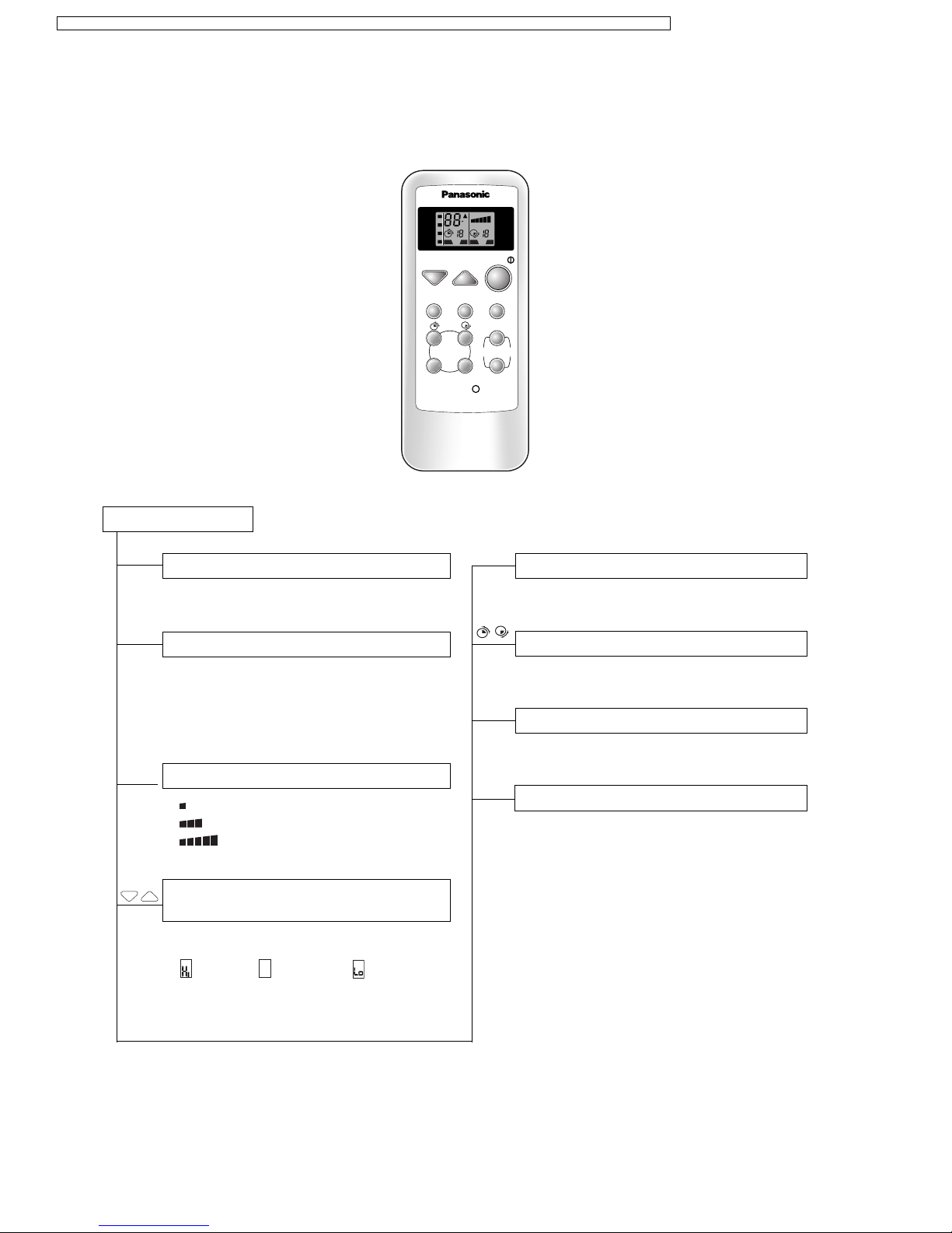
Remote Control Transmitter
Remote Control
Operation START/STOP
Operation Mode Selection
Indoor Fan Speed Selection
Room Temperature Setting / Time
Setting
Sleep Mode Auto-Control
●
Starts/Stops when the button is pressed
Timer Operation Selection
●
12 hours ON/OFF Dual Timer Setting
Timer Operation Set/Cancel
●
Set/Cancel the selected Timer Operation
Airflow Direction Control
●
Airflow Direction Manual Control
●
Automatic Airflow Direction Control
SET/C
●
Temperature Setting (20°C to 30°C)
●
(higher), (standard), (lower)
... Automatic Operation
•
AUTO
Automatic Operation Mode
•
COOL
Cooling Operation Mode
•
DRY
Soft Dry Operation Mode
•
FAN
Air Circulation Mode
• Low Fan Speed
• Medium Fan Speed
• High Fan Speed
TEMP
SLEEP
AUTO
COOL
FAN
FAN
SPEED
OFF/ON
TEMP
MODE SLEEP
FAN SPEED
AUTO
MANUAL
TIMER
AIR SWING
OFF/ON SET/C
RESET
DRY
C
H H
OFF ON OFF ON
2
CS-C12ATP5 CU-C12ATP5 / CS-C18ATP5 CU-C18ATPT5 / CS-C24ATP5 CU-C24ATPT5 / CS-C18ATP6 CU-C18ATPT6 / CS-C24ATP6 CU-C24ATPT6
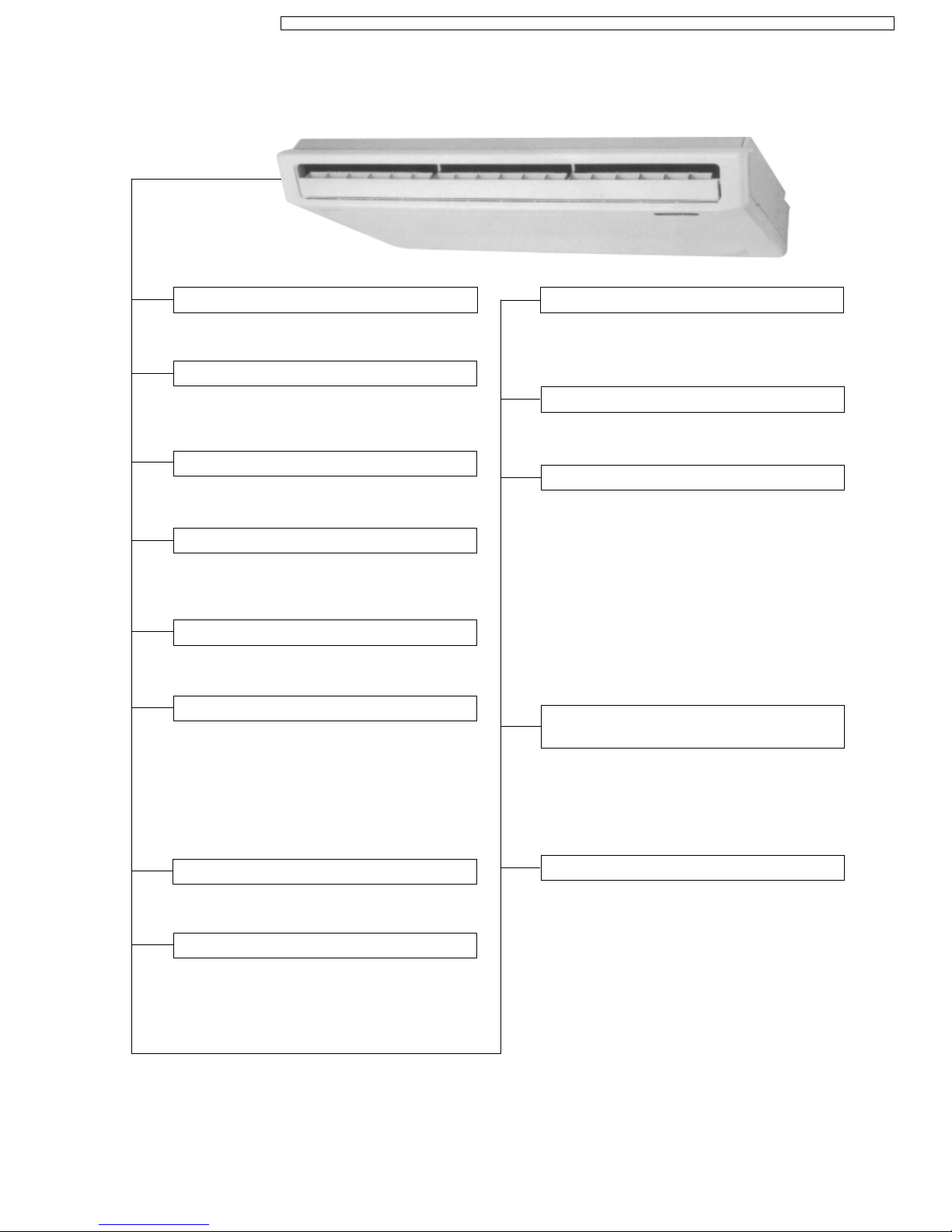
Indoor Unit
Sensing The Room Temperature
●
Room Temperature Sensor (thermistor)
Starting Current Control
●
Indoor Fan is delayed for 1.6 seconds at the
starting
Time Delay Safety Control
●
Restarting is inhibited for apporox. 3 minutes
Circuit Protection Control
●
30 seconds forced operation of the
compressor
Indoor Fan Speed Control
●
High, Med, Low
Operation Indication Lamps (LED)
●
POWER
(green).........Lights up in operation
●
AIR SWING
(red)......... Automatic Airflow
Direction in operation
●
TIMER
(orange) ........ Timer in operation
●
SLEEP
(orange) ........ Sleep Mode Auto in
operation
Soft Dry Operation Mode
●
Intermittent operation of Fan at low speed
Room Temperature Control
●
Maintains the room temperature accordance
with the Setting Temp.
Air Circulation Operation Mode
(Fan only operation)
●
Low Fan Speed operation interlocked with
the setting temp.
Automatic Restarting Control
●
7 minutes automatic restarting at Cooling,
Soft Dry operation
Sleep Mode Auto Control
●
(Can be obtained with Cooling, Soft Dry,
Automatic Operation Mode.)
●
The Fan is switched to Low fan speed and the
unit will be stopped after 5 hours
●
The setting temperature will be raised by 1°C
at the starting and by 1°C one hour later
●
When the room temperature becomes a level
ideal for sleep, the operation 20 minutes off
and 10 minutes on will be repeated
●
5 minutes automatic restarting is activated
instead of 7 minutes
Anti-freezing Control For The
Evaporator
●
Compressor will be stopped when the
Evaporator’s piping temperature is 0°C or
less for three minutes
●
Restarting at 12°C or higher (Time Delay
Safety Control has a priority)
Airflow Direction Control
Automatic Airflow Direction Control
●
The louver automatically swings up and down
(Cooling, Soft Dry)
●
The louver is set at 30° downward during Air
Circulation Operation
●
The louver is set at horizontal when the fan is
stopped
Airflow Direction Manual Control
●
Can be set within a range at horizontal to 30°
downward
3
CS-C12ATP5 CU-C12ATP5 / CS-C18ATP5 CU-C18ATPT5 / CS-C24ATP5 CU-C24ATPT5 / CS-C18ATP6 CU-C18ATPT6 / CS-C24ATP6 CU-C24ATPT6
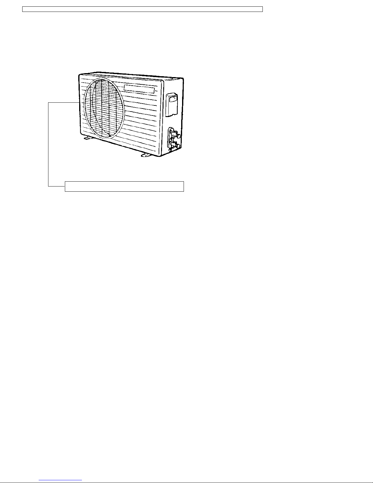
Outdoor Unit
Overload Protector
4
CS-C12ATP5 CU-C12ATP5 / CS-C18ATP5 CU-C18ATPT5 / CS-C24ATP5 CU-C24ATPT5 / CS-C18ATP6 CU-C18ATPT6 / CS-C24ATP6 CU-C24ATPT6
2 Product Specifications
Unit CS-C12ATP5 CU-C12ATP5
Cooling Capacity kW
BTU/h
kcal/h
3.45; 3.45; 3.50
11,700; 11,700; 11,900
2,970; 2,970; 3,050
Moisture Removal l/h
Pint/h
2.0
4.2
Power Source Phase
V
Cycle
Single
220; 230; 240
50
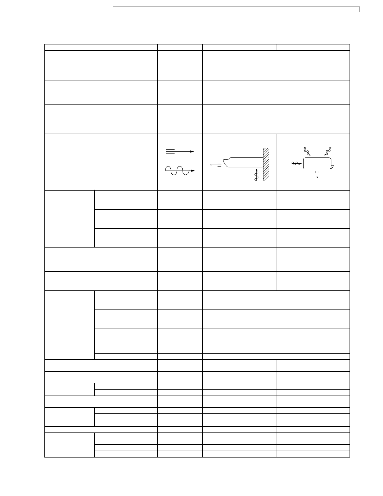
Airflow Method OUTLET
INTAKE
SIDE VIEW TOP VIEW
Air Volume Indoor Air (Lo) m3/min (cfm) 8.9 (314) —
Indoor Air (Me) m3/min (cfm) 9.6 (338) —
Indoor Air (Hi) m3/min (cfm) 10.0 (350) —
Noise Level dB (A) High 43; 44; 44
Low 38; 40; 40
High 46; 47; 47
Power Level dB (A) High 57 High 62
Electrical Data Input kW 1.27; 1.28; 1.30
Running Current A 6.0; 5.9; 5.8
EER W/W
BTU/hW
2.72; 2.70; 2.69
9.2; 9.2; 9.2
Starting Current A 25
Piping Connection Port
(Flare piping)
inch
inch
G ; Half Union 1/2”
L ; Half Union 1/4”
G ; 3-way valve 1/2”
L ; 2-way valve 1/4”
Pipe Size
(Flare piping)
inch
inch
G (gas side) ; 1/2”
L (liquid side) ; 1/4”
G (gas side) ; 1/2”
L (liquid side) ; 1/4”
Drain
Hose
Inner diameter mm 20 —
Length m 0.6 —
Power Cord Length
Number of core-wire
m 2.3
3 (1.0 mm
2
)
—
—
Dimensions Height inch (mm) 6 - 1/2 (165) 19 - 29/32 (505)
Width inch (mm) 43 - 5/16 (1,100) 30 - 23/32 (780)
Depth inch (mm) 25 - 19/32 (650) 9 - 21/32 (245)
Net Weight lb (kg) 62 (28) 82 (37)
Compressor Type — Rotary (1 cylinder)
rolling piston type
Motor Type — Induction (2-poles)
Rated Output W — 1,100
5
CS-C12ATP5 CU-C12ATP5 / CS-C18ATP5 CU-C18ATPT5 / CS-C24ATP5 CU-C24ATPT5 / CS-C18ATP6 CU-C18ATPT6 / CS-C24ATP6 CU-C24ATPT6

Unit CS-C12ATP5 CU-C12ATP5
Air Circulation Type SIROCCO Propeller Fan
Material STYLAC 181 AES + Glass Fiber 12%
Motor Type Induction (4-poles) Induction (6-poles)
Input W 45.6 58.6
Rated Output W 20 20
Fan Speed Low rpm 980 —
Medium rpm 1,055 —
High rpm 1,100 730
Heat Exchanger Description Evaporator Condenser
Tube material Copper Copper
Fin material Aluminium Aluminium
Fin Type Louver Fin Corrugated Fin
Row / Stage (Plate fin configuration, forced draft)
1×10 2×19
FPI 21 16
Size (W × H × L) mm 900 × 254 × 22 706 × 482 × 44
Refrigerant Control Device — Capillary Tube
Refrigeration Oil (c.c) — SUNISO 4GDID or ATMOS M60
(410)
Refrigerant (R-22) g (oz.) — 1,000 (35.5)
Thermostat Electronic Control —
Protection Device — Overload Protector
Length mm — 625
Capillary Tube Flow Rate l/min — 13.5
Inner Diameter mm — 1.6
Air Filter Material
Style
P.P.
Honeycomb
—
Capacity Control Capillary Tube
Compressor Capacitor µF, VAC — 30 µF, 370VAC
Fan Motor Capacitor µF, VAC 1.2 µF, 450VAC 1.2 µF, 400VAC
•
Specifications are subject to change without notice for further improvement.
6
CS-C12ATP5 CU-C12ATP5 / CS-C18ATP5 CU-C18ATPT5 / CS-C24ATP5 CU-C24ATPT5 / CS-C18ATP6 CU-C18ATPT6 / CS-C24ATP6 CU-C24ATPT6
Unit CS-C18ATP5 CU-C18ATPT5
Cooling Capacity kW
Btu/h
kcal/h
5.15; 5.20; 5.30
17,500; 17,700; 18,000
4,430; 4,470; 4,560
Moisture Removal l/h
Pint/h
2.9
6.1
Power Source Phase
V
Cycle
Single
220; 230; 240
50
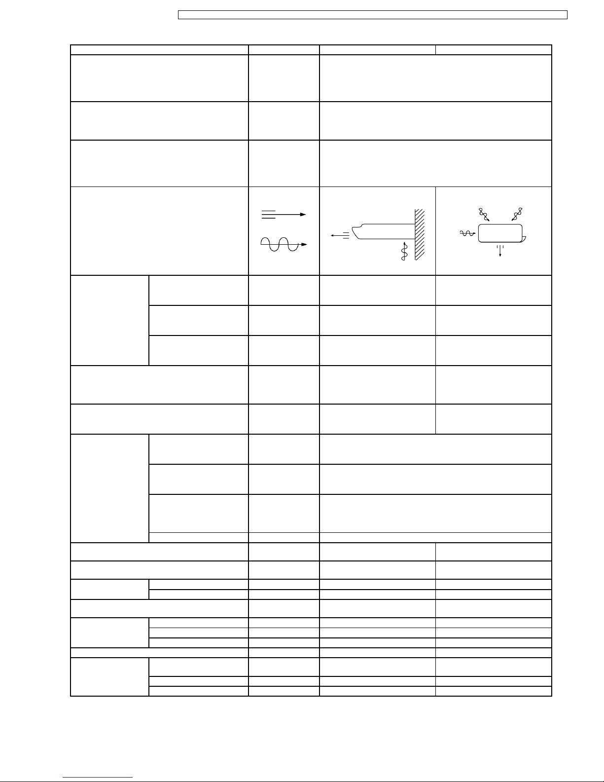
Airflow Method OUTLET
INTAKE
SIDE VIEW TOP VIEW
Air Volume Indoor Air (Lo) m3/min (cfm) 10.4 (354) —
Indoor Air (Me) m3/min (cfm) 10.7 (379) —
Indoor Air (Hi) m3/min (cfm) 11.5 (400) —
Noise Level dB (A) High 50; 51; 51
Low 40; 46; 46
High 54; 56; 56
Power Level dB (A) High 64 High 71
Electrical Data Input kW 2.08; 2.10; 2.19
Running Current A 10.3; 10.5; 10.7
EER W/W
BTU/hW
2.48; 2.48; 2.42
8.4; 8.4; 8.2
Starting Current A 47
Piping Connection Port
(Flare piping)
inch
inch
G ; Half Union 1/2”
L ; Half Union 1/4”
G ; 3-way valve 1/2”
L ; 2-way valve 1/4”
Pipe Size
(Flare piping)
inch
inch
G (gas side) ; 1/2”
L (liquid side) ; 1/4”
G (gas side) ; 1/2”
L (liquid side) ; 1/4”
Drain
Hose
Inner diameter mm 20 —
Length m 0.6 —
Power Cord Length
Number of core-wire
m 2.3
3 (1.5 mm
2
)
—
—
Dimensions Height inch (mm) 6 - 1/2 (165) 26 - 31/32 (685)
Width inch (mm) 43 - 5/16 (1,100) 31 - 1/2 (800)
Depth inch (mm) 25 - 19/32 (650) 11 - 13/16 (300)
Net Weight lb (kg) 66 (30) 126 (57)
Compressor Type — Rotary (1 cylinder)
rolling piston type
Motor Type — Induction (2-poles)
Rated Output W — 1,700
7
CS-C12ATP5 CU-C12ATP5 / CS-C18ATP5 CU-C18ATPT5 / CS-C24ATP5 CU-C24ATPT5 / CS-C18ATP6 CU-C18ATPT6 / CS-C24ATP6 CU-C24ATPT6

Unit CS-C18ATP5 CU-C18ATPT5
Air Circulation Type SIROCCO Propeller Fan
Material STYLAC 181 CE10G15 JSR
Motor Type Induction (4-poles) Induction (4-poles)
Input W 66.00 136.8 (High)
Rated Output W 40 65
Fan Speed Low rpm 1,160 610
Medium rpm 1,250 —
High rpm 1,340 960
Heat Exchanger Description Evaporator Condenser
Tube material Copper Copper
Fin material Aluminium Aluminium
Fin Type Louver Fin Corrugated Fin
Row / Stage (Plate fin configuration, forced draft)
2 × 10 2 × 26
FPI 20 14
Size (W × H × L) mm 900 × 254 × 44 796 × 660 × 44
Refrigerant Control Device — Capillary Tube
Refrigeration Oil (c.c) — SUNISO 4GDID or ATMOS M60
(700)
Refrigerant (R-22) g (oz.) — 1,550 (54.7)
Thermostat Electronic Control —
Protection Device — Inner Protector
Length mm — 625
Capillary Tube Flow Rate l/min — 13.5
Inner Diameter mm — 1.6
Air Filter Material
Style
P.P.
Honeycomb
—
Capacity Control Capillary Tube
Compressor Capacitor µF, VAC — 35 µF, 370VAC
Fan Motor Capacitor µF, VAC 1.2 µF, 450VAC 3.5 µF, 400VAC
•
Specifications are subject to change without notice for further improvement.
8
CS-C12ATP5 CU-C12ATP5 / CS-C18ATP5 CU-C18ATPT5 / CS-C24ATP5 CU-C24ATPT5 / CS-C18ATP6 CU-C18ATPT6 / CS-C24ATP6 CU-C24ATPT6
Unit CS-C18ATP6 CU-C18ATPT6
Cooling Capacity kW
Btu/h
kcal/h
5.30
18,100
4,560
Moisture Removal l/h
Pint/h
2.9
6.1
Power Source Phase
V
Cycle
Single
220
60
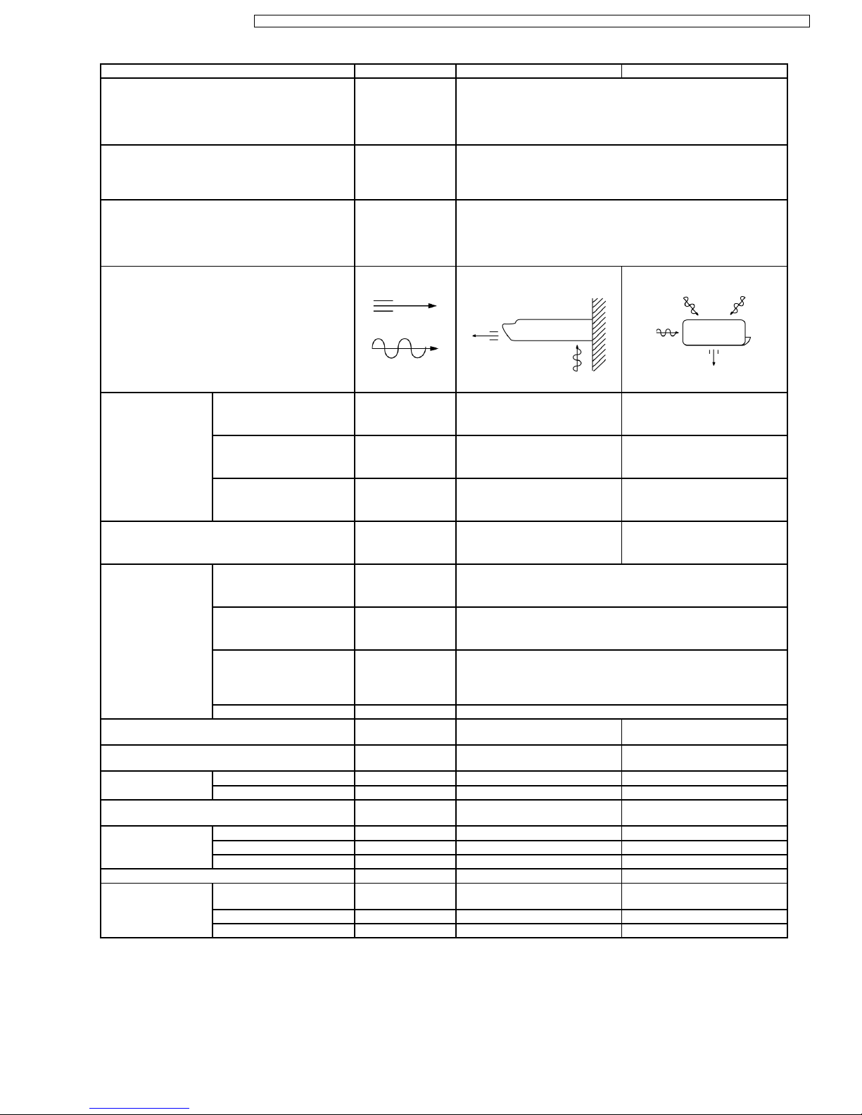
Airflow Method OUTLET
INTAKE
SIDE VIEW TOP VIEW
Air Volume Indoor Air (Lo) m3/min (cfm) 10.4 (354) —
Indoor Air (Me) m3/min (cfm) 10.7 (379) —
Indoor Air (Hi) m3/min (cfm) 11.5 (400) —
Noise Level dB (A) High 50; Low 44 High 52
Electrical Data Input kW 2.07
Running Current A 9.6
EER W/W
BTU/hW
2.56
8.7
Starting Current A 40
Piping Connection Port
(Flare piping)
inch
inch
G ; Half Union 1/2”
L ; Half Union 1/4”
G ; 3-way valve 1/2”
L ; 2-way valve 1/4”
Pipe Size
(Flare piping)
inch
inch
G (gas side) ; 1/2”
L (liquid side) ; 1/4”
G (gas side) ; 1/2”
L (liquid side) ; 1/4”
Drain
Hose
Inner diameter mm 20 —
Length m 0.6 —
Power Cord Length
Number of core-wire
m 2.3
3 (1.5 mm
2
)
—
—
Dimensions Height inch (mm) 6 - 1/2 (165) 26 - 31/32 (685)
Width inch (mm) 43 - 5/16 (1,100) 31 - 1/2 (800)
Depth inch (mm) 25 - 19/32 (650) 11 - 13/16 (300)
Net Weight lb (kg) 66 (30) 121 (55)
Compressor Type — Rotary (1 cylinder)
rolling piston type
Motor Type — Induction (2-poles)
Rated Output W — 1,400
9
CS-C12ATP5 CU-C12ATP5 / CS-C18ATP5 CU-C18ATPT5 / CS-C24ATP5 CU-C24ATPT5 / CS-C18ATP6 CU-C18ATPT6 / CS-C24ATP6 CU-C24ATPT6

Unit CS-C18ATP6 CU-C18ATPT6
Air Circulation Type SIROCCO Propeller Fan
Material STYLAC 181 CE10G15 JSR
Motor Type Induction (4-poles) Induction (4-poles)
Input W 61.27 93.60 (High)
Rated Output W 70 95
Fan Speed Low rpm 1,050 575
Medium rpm 1,125 —
High rpm 1,215 765
Heat Exchanger Description Evaporator Condenser
Tube material Copper Copper
Fin material Aluminium Aluminium
Fin Type Louver Fin Corrugated Fin
Row / Stage (Plate fin configuration, forced draft)
2 × 10 2 × 26
FPI 20 14
Size (W × H × L) mm 900 × 254 × 44 796 × 660 × 44
Refrigerant Control Device — Capillary Tube
Refrigeration Oil (c.c) — SUNISO 4GDID or ATMOS M60
(700)
Refrigerant (R-22) g (oz.) — 1,900 (67.1)
Thermostat Electronic Control —
Protection Device — Inner Protector
Length mm — 625
Capillary Tube Flow Rate l/min — 13.5
Inner Diameter mm — 1.6
Air Filter Material
Style
P.P.
Honeycomb
—
Capacity Control Capillary Tube
Compressor Capacitor µF, VAC — 35 µF, 370VAC
Fan Motor Capacitor µF, VAC 1.2 µF, 450VAC 3.5 µF, 400VAC
•
Specifications are subject to change without notice for further improvement.
10
CS-C12ATP5 CU-C12ATP5 / CS-C18ATP5 CU-C18ATPT5 / CS-C24ATP5 CU-C24ATPT5 / CS-C18ATP6 CU-C18ATPT6 / CS-C24ATP6 CU-C24ATPT6
Unit CS-C24ATP5 CU-C24ATPT5
Cooling Capacity kW
Btu/h
kcal/h
6.30; 6.30; 6.35
21,500; 21,500; 21,600
5,420; 5,420; 5,440
Moisture Removal l/h
Pint/h
3.6
7.6
Power Source Phase
V
Cycle
Single
220; 230; 240
50
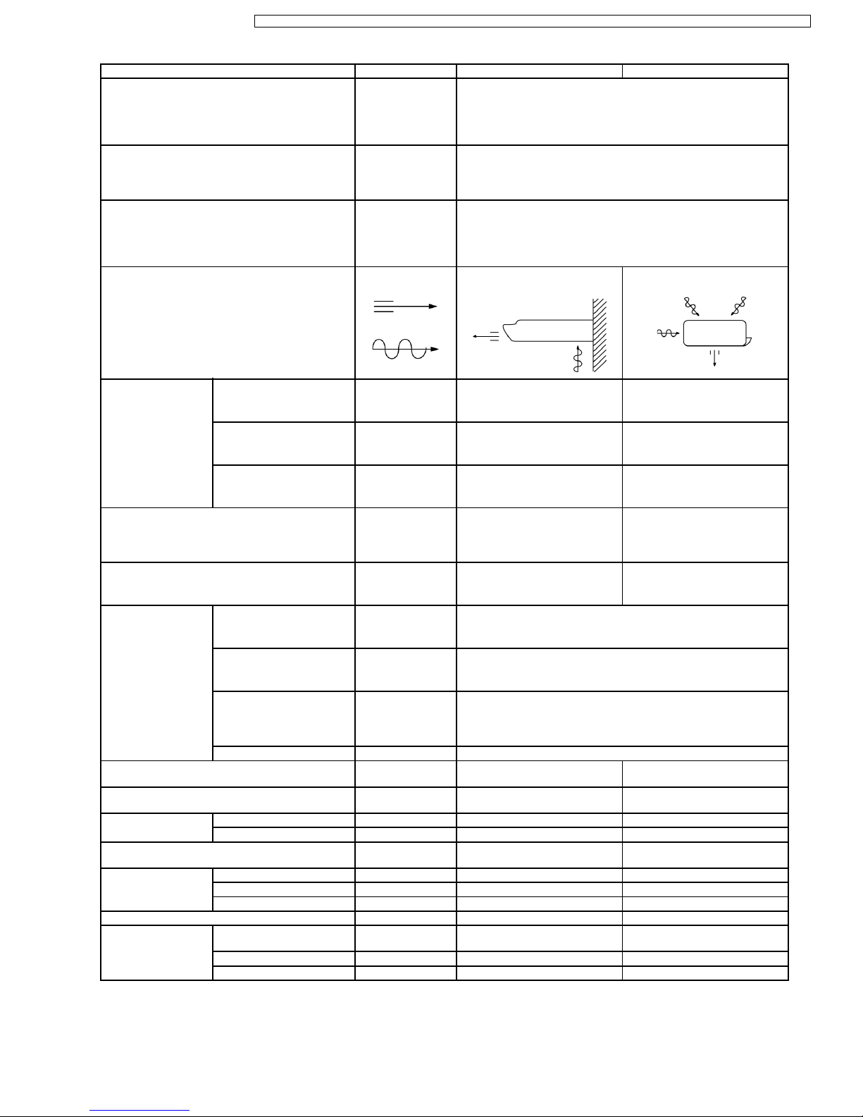
Airflow Method OUTLET
INTAKE
SIDE VIEW TOP VIEW
Air Volume Indoor Air (Lo) m3/min (cfm) 10.4 (370) —
Indoor Air (Me) m3/min (cfm) 11.2 (395) —
Indoor Air (Hi) m3/min (cfm) 12.0 (420) —
Noise Level dB (A) High 51; 52; 52
Low 45; 47; 47
High 57; 59; 59
Power Level dB (A) High 65 High 74
Electrical Data Input kW 2.75; 2.91; 2.91
Running Current A 13.3; 13.5; 13.6
EER W/W
BTU/hW
2.29; 2.21; 2.18
7.8; 7.5; 7.4
Starting Current A 59
Piping Connection Port
(Flare piping)
inch
inch
G ; Half Union 5/8”
L ; Half Union 1/4”
G ; 3-way valve 5/8”
L ; 2-way valve 1/4”
Pipe Size
(Flare piping)
inch
inch
G (gas side) ; 5/8”
L (liquid side) ; 1/4”
G (gas side) ; 5/8”
L (liquid side) ; 1/4”
Drain
Hose
Inner diameter mm 20 —
Length m 0.6 —
Power Cord Length
Number of core-wire
m 2.3
3 (2.5 mm
2
)
—
—
Dimensions Height inch (mm) 6 - 1/2 (165) 26 - 31/32 (685)
Width inch (mm) 43 - 5/16 (1,100) 31 - 1/2 (800)
Depth inch (mm) 25 - 19/32 (650) 11 - 13/16 (300)
Net Weight lb (kg) 66 (30) 130 (59)
Compressor Type — Rotary (1 cylinder)
rolling piston type
Motor Type — Induction (2-poles)
Rated Output W — 2,200
11
CS-C12ATP5 CU-C12ATP5 / CS-C18ATP5 CU-C18ATPT5 / CS-C24ATP5 CU-C24ATPT5 / CS-C18ATP6 CU-C18ATPT6 / CS-C24ATP6 CU-C24ATPT6
Unit CS-C24ATP5 CU-C24ATPT5
Air Circulation Type SIROCCO Propeller Fan
Material STYLAC 181 CE10G15 JSR
Motor Type Induction (4-poles) Induction (4-poles)
Input W 66.00 141.7 (High)
Rated Output W 40 80
Fan Speed Low rpm 1,160 685
Medium rpm 1,250 —
High rpm 1,340 1,053
Heat Exchanger Description Evaporator Condenser
Tube material Copper Copper
Fin material Aluminium Aluminium
Fin Type Louver Fin Corrugated Fin
Row / Stage (Plate fin configuration, forced draft)
2 × 10 2 × 26
FPI 20 14
Size (W × H × L) mm 900 × 254 × 44 796 × 660 × 44
Refrigerant Control Device — Capillary Tube
Refrigeration Oil (c.c) — SUNISO 4GDID or ATMOS M60
(700)
Refrigerant (R-22) g (oz.) — 1,900 (67.1)
Thermostat Electronic Control —
Protection Device — Inner Protector
Length mm — 1,170
Capillary Tube Flow Rate l/min — 21.1
Inner Diameter mm — 2.4
Air Filter Material
Style
P.P.
Honeycomb
—
Capacity Control Capillary Tube
Compressor Capacitor µF, VAC — 45 µF, 370VAC
Fan Motor Capacitor µF, VAC 1.2 µF, 450VAC 3.5 µF, 400VAC
•
Specifications are subject to change without notice for further improvement.
12
CS-C12ATP5 CU-C12ATP5 / CS-C18ATP5 CU-C18ATPT5 / CS-C24ATP5 CU-C24ATPT5 / CS-C18ATP6 CU-C18ATPT6 / CS-C24ATP6 CU-C24ATPT6
Unit CS-C24ATP6 CU-C24ATPT6
Cooling Capacity kW
Btu/h
kcal/h
6.45
22,200
5,550
Moisture Removal l/h
Pint/h
4.0
8.4
Power Source Phase
V
Cycle
Single
220
60
Airflow Method OUTLET
INTAKE
SIDE VIEW TOP VIEW
Air Volume Indoor Air (Lo) m3/min (cfm) 10.5 (370) —
Indoor Air (Me) m3/min (cfm) 11.2 (395) —
Indoor Air (Hi) m3/min (cfm) 12.0 (420) —
Noise Level dB (A) High 51; Low 45 High 55
Electrical Data Input kW 2.65
Running Current A 13.0
EER W/W
BTU/hW
2.43
8.3
Starting Current A 50
Piping Connection Port
(Flare piping)
inch
inch
G ; Half Union 5/8”
L ; Half Union 1/4”
G ; 3-way valve 5/8”
L ; 2-way valve 1/4”
Pipe Size
(Flare piping)
inch
inch
G (gas side) ; 5/8”
L (liquid side) ; 1/4”
G (gas side) ; 5/8”
L (liquid side) ; 1/4”
Drain
Hose
Inner diameter mm 20 —
Length m 0.6 —
Power Cord Length
Number of core-wire
m 2.3
3 (3.5 mm
2
)
—
—
Dimensions Height inch (mm) 6 - 1/2 (165) 26 - 31/32 (685)
Width inch (mm) 43 - 5/16 (1,100) 31 - 1/2 (800)
Depth inch (mm) 25 - 19/32 (650) 11 - 13/16 (300)
Net Weight lb (kg) 66 (30) 130 (59)
Compressor Type — Rotary (1 cylinder)
rolling piston type
Motor Type — Induction (2-poles)
Rated Output W — 1,800
13
CS-C12ATP5 CU-C12ATP5 / CS-C18ATP5 CU-C18ATPT5 / CS-C24ATP5 CU-C24ATPT5 / CS-C18ATP6 CU-C18ATPT6 / CS-C24ATP6 CU-C24ATPT6

Unit CS-C24ATP6 CU-C24ATPT6
Air Circulation Type SIROCCO Propeller Fan
Material STYLAC 181 CE10G15 JSR
Motor Type Induction (4-poles) Induction (4-poles)
Input W 61.27 108.3 (High)
Rated Output W 70 118
Fan Speed Low rpm 1,050 660
Medium rpm 1,125 —
High rpm 1,215 895
Heat Exchanger Description Evaporator Condenser
Tube material Copper Copper
Fin material Aluminium Aluminium
Fin Type Louver Fin Corrugated Fin
Row / Stage (Plate fin configuration, forced draft)
2 × 10 2 × 26
FPI 20 14
Size (W × H × L) mm 900 × 254 × 44 796 × 660 × 44
Refrigerant Control Device — Capillary Tube
Refrigeration Oil (c.c) — SUNISO 4GDID or ATMOS M60
(700)
Refrigerant (R-22) g (oz.) — 1,900 (67.1)
Thermostat Electronic Control —
Protection Device — Inner Protector
Length mm — 1,170
Capillary Tube Flow Rate l/min — 21.1
Inner Diameter mm — 2.4
Air Filter Material
Style
P.P.
Honeycomb
—
Capacity Control Capillary Tube
Compressor Capacitor µF, VAC — 45 µF, 370VAC
Fan Motor Capacitor µF, VAC 1.2 µF, 450VAC 3.5 µF, 400VAC
•
Specifications are subject to change without notice for further improvement.
14
CS-C12ATP5 CU-C12ATP5 / CS-C18ATP5 CU-C18ATPT5 / CS-C24ATP5 CU-C24ATPT5 / CS-C18ATP6 CU-C18ATPT6 / CS-C24ATP6 CU-C24ATPT6
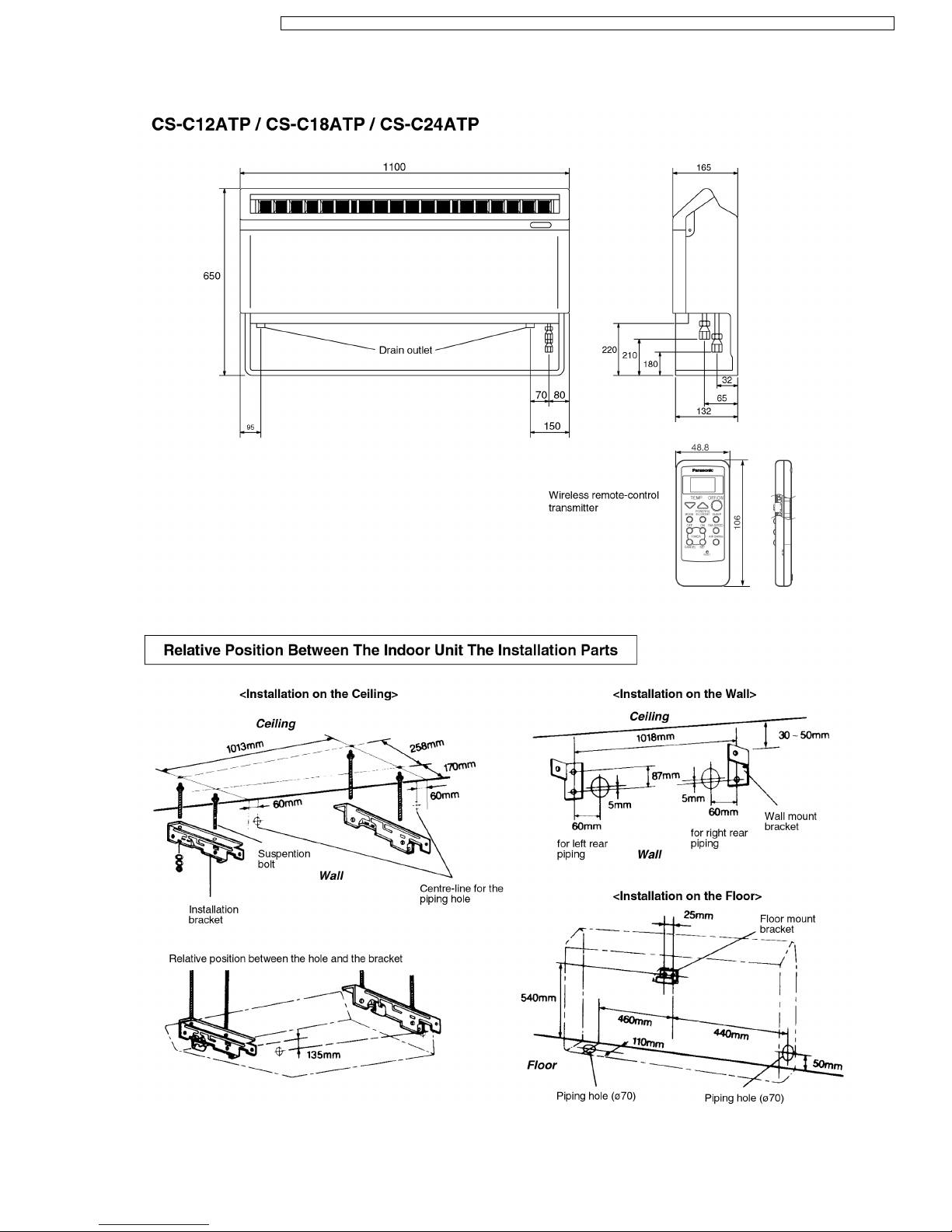
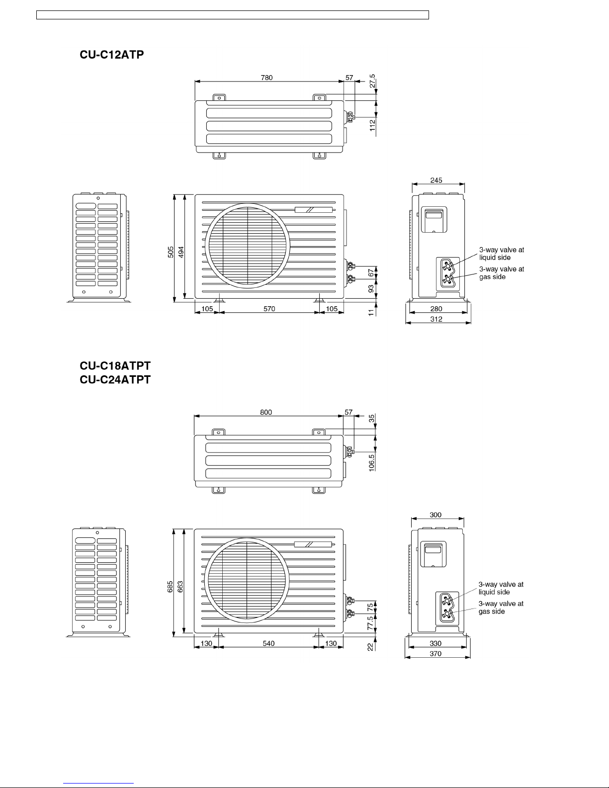
3 Dimensions
15
CS-C12ATP5 CU-C12ATP5 / CS-C18ATP5 CU-C18ATPT5 / CS-C24ATP5 CU-C24ATPT5 / CS-C18ATP6 CU-C18ATPT6 / CS-C24ATP6 CU-C24ATPT6
16
CS-C12ATP5 CU-C12ATP5 / CS-C18ATP5 CU-C18ATPT5 / CS-C24ATP5 CU-C24ATPT5 / CS-C18ATP6 CU-C18ATPT6 / CS-C24ATP6 CU-C24ATPT6
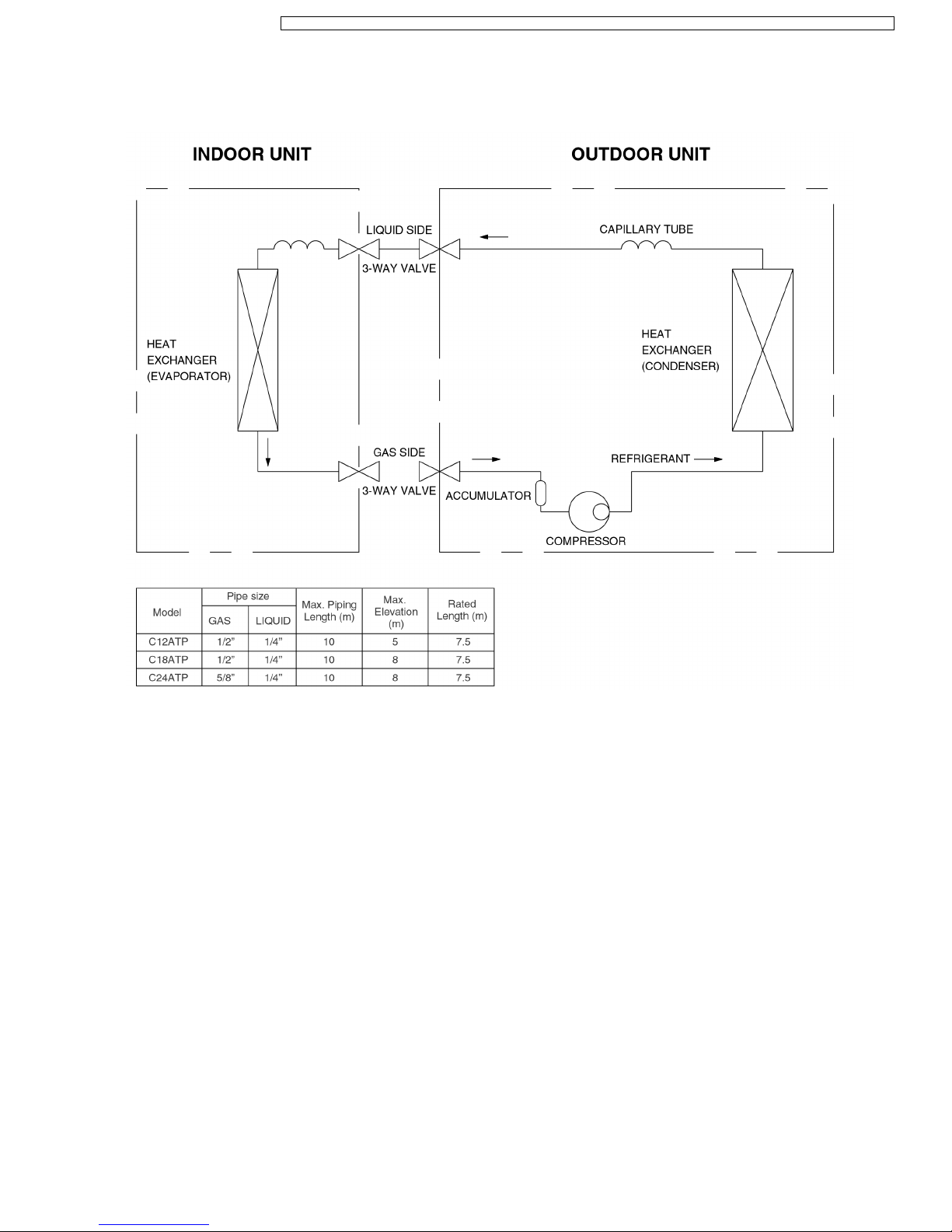
4 Refrigeration Cycle Diagram
17
CS-C12ATP5 CU-C12ATP5 / CS-C18ATP5 CU-C18ATPT5 / CS-C24ATP5 CU-C24ATPT5 / CS-C18ATP6 CU-C18ATPT6 / CS-C24ATP6 CU-C24ATPT6
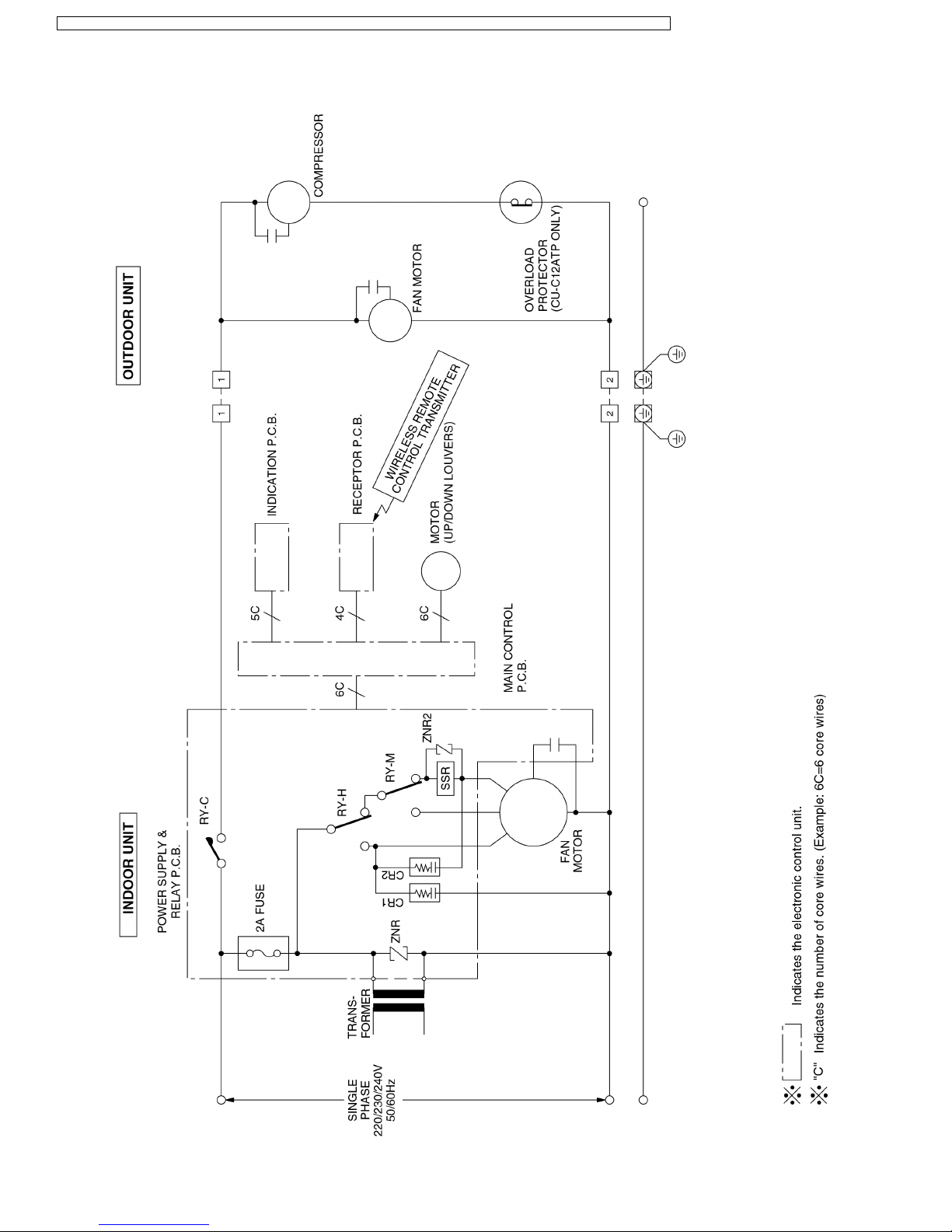
5 Block Diagram
18
CS-C12ATP5 CU-C12ATP5 / CS-C18ATP5 CU-C18ATPT5 / CS-C24ATP5 CU-C24ATPT5 / CS-C18ATP6 CU-C18ATPT6 / CS-C24ATP6 CU-C24ATPT6
 Loading...