

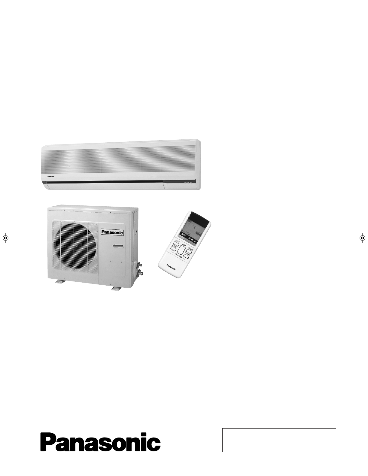
Panasonic CS-C181KE, CU-C181KE, CS-C241KE, CU-C241KE Service Manual
ORDER NO. MAC9806008C2
Service Manual
Room Air Conditioners
CS-C181KE / CU-C181KE
CS-C241KE / CU-C241KE
Contents
● Features ..........................................................1
● Functions ...................................................2 – 4
● Product Specifications ...............................5 – 8
● Dimensions ..............................................9 – 10
● Refrigeration Cycle Diagram .........................10
● Block Diagram ...............................................11
● Wiring Diagram .............................................. 12
● Operation Details ................................... 13 – 19
● Installation Information ..........................20 – 21
● 3-way Valves .........................................22 – 28
● Servicing Information ............................. 29 – 32
● Troubleshooting Guide ..........................33 – 34
● Technical Data.......................................35 – 36
● Exploded View .........................................37, 39
● Replacement Parts List ...........................38, 40
● Electronic Parts List ....................................... 41
1998 Matsushita Air-Conditioning Corp. Sdn. Bhd.
(183914D)
All rights reserved. Unauthorized copying and distribution is a violation of law.
CS-C181KE
!
WARNING
This service information is designed for experienced repair technicians only and is not designed for use by the general public. It does not contain
warnings or cautions to advise non-technical individuals of potential dangers in attempting to service a product. Products powered by electricity
should be serviced or repaired only by experienced professional technicians. Any attempt to service or repair the product or products dealt with
in this service information by anyone else could result in serious injury or death.
!
PRECAUTION OF LOW TEMPERATURE
In order to avoid frostbite, be assured of no refrigerant leakage during the installation or repairing of refrigeration circuit.
Features
• High Efficiency
• High Efficiency Airflow Circuit
• Compact Design
• Removable and Washable
Front Panel
• Auto Restart after Power Failure
• Long Piping up to 25m
• Deodorizing Air Filter
• Deodorizing Control during
operation
– 1 –
Functions
Remote Control
CS-C181KE
OFF / ON I
MODE
FAN SPEED
AIR SWING
Operation OFF / ON
Operation Mode Selection
• AUTO Automatic Operation Mode
• COOL Cooling Operation Mode
• DRY Soft Dry Operation Mode
• FAN Air Circulation Mode
Indoor Fan Speed Selection
• h j k Low Speed
l
• h j k Medium Speed
lll
• h j k High Speed
lllll
• AUTOFAN Automatic Fan Speed
Airflow Direction Control
• SWING Automatic Airflow Direction
Control
• MANUAL Airflow Direction Manual Control
TEMP.
ON-TIMER
OFF-TIMER
TIME
SET
CANCEL
CLOCK
(q)
Room Temperature Setting
• Temperature Setting (16˚C to 30˚C)
• Automatic Operation
m / n 2˚C lower than standard
n Standard
n - o 2˚C higher than standard
Timer Operation Selection
• 24-hour, OFF / ON Real Timer Setting.
Time / Timer Setting
• Hours and minutes setting.
Timer Operation Set / Cancel
• ON Timer and OFF Timer setting and
cancellation.
Clock Setting
• Current time setting.
– 2 –
SLEEP
Sleep Mode Operation OFF / ON
CS-C181KE
Functions
Indoor Unit
POWER I
AUTO
OFF / ON
TEST RUN
OFF / ON
Power Switch OFF / ON
Temporary Operation Switch
• Used when the remote control cannot be
used.
Remote Control Signal Receiving
Sound Control
• It can be controlled by pressing Temporary
Operation Switch for 10 seconds.
Operation Test Running / Pump
Down Switch
• Used when test running or servicing.
Operation Indication Lamps (LED)
• POWER (Red)...... Lights up in operation,
blinks in Automatic
Operation Mode judging
• SLEEP (Orange)..... Lights up in Sleep
Mode Operation
• TIMER (Orange)..... Lights up in Timer
Setting
Operation Mode
• Cooling, Soft Dry, Air Circulation and
Automatic Mode.
Time Delay Safety Control
• Restarting is inhibited for appro. 3 minutes.
7 Minutes Time Save Control
• Cooling Operation only.
Auto Restart Control
• Operation is restarted after power failure
at previous setting mode.
Anti-Freezing Control
• Anti-Freezing control for indoor heat
exchanger. (Cooling and Soft Dry)
Sleep Mode Auto Control
• Indoor Fan operates at Low fan speed.
• Operation stops after 8 hours.
Indoor Fan Speed Control
• High, Medium and Low.
• Automatic Fan Speed Mode
– Cooling : Fan rotates at Hi and Me
speed. Deodorizing control is
available.
– Soft Dry : Fan rotates at SLo and Lo
speed. Deodorizing control is
available.
Airflow Direction Control
• Automatic air swing and manual adjusted
by remote control for vertical airflow.
• Manually adjusted by hand for horizontal
airflow.
Starting Current Control
• Indoor Fan is delayed for 1.6 seconds when
compressors, Outdoor Fan and Indoor Fan
start simultaneously.
– 3 –

Functions
Outdoor Unit
CS-C181KE
Overload Protector
• Inner protector
60 Secs. Forced Operation Control
• Once the compressor is activated, it does
not stop for 60 secs. (Stops immediately
with remote control stop signal.)
Outdoor Fan Operation Control
•
4-pole induction motor (2-speed)
• For Cooling or Soft Dry Operation
Hi-speed … when outdoor temperature
reaches to 31°C
Lo-speed … when outdoor temperature
reaches to 29°C
– 4 –
CS-C181KE
Product Specifications
Cooling Capacity
Moisture Removal
Power Source
Airflow Method
Air Volume
Noise Level
Electrical
Data
Indoor Air (Lo)
Indoor Air (Me)
Indoor Air (Hi)
Outdoor Air
Input
Running Current
Unit
kW
Btu/h
s/h
Pint/h
Phase
V
Cycle
OUTLET
INTAKE
3
/min (cfm)
m
3
m
/min (cfm)
3
m
/min (cfm)
m3/min (cfm)
dB (A)
W
A
CS-C181KE
5.40 - 5.30
18,400 - 18,100
240 - 220
SIDE VIEW
11.2 (400)
13.0 (460)
13.7 (480)
–
High 43 - 42, Low 38 - 37
2,080 - 1,930
10.7 - 10.0
CU-C181KE
2.9
6.1
Single
50
TOP VIEW
–
–
–
11.7 (410)
High 56 - 54
COP
Starting Current
Piping Connection Port
(Flare piping)
Pipe Size
(Flare piping)
Drain
Hose
Power Cord Length
Dimensions
Net Weight
Compressor
Air Circulation
Inner diameter
Length
Number of core-wire
Motor Type
Rated Output
Motor Type
Fan Low
Speed Medium
Height
Width
Depth
Type
Type
Material
Input
Rated Output
High
W/W
A
inch
inch
inch
inch
mm
m
m
inch (mm)
inch (mm)
inch (mm)
lb (kg)
kW
W
W
rpm
rpm
rpm
G ; Half Union 1/2"
L ; Half Union 1/4"
G (gas side) ; 1/2"
L (liquid side) ; 1/4"
16
0.75
2.1
2
3 (1.5 mm
11-7/16 (290)
38-19/32 (980)
7-11/16 (195)
29 (13)
Cross-flow Fan
AS + Glass Fiber 30%
Induction (4-poles)
)
–
–
–
51
20
1,005
1,085
1,155
2.60 - 2.75
51
G ; 3-way valve 1/2"
L ; 3-way valve 1/4"
G (gas side) ; 1/2"
L (liquid side) ; 1/4"
–
–
–
–
26-31/32 (685)
31-1/2 (800)
11-13/16 (300)
130 (59)
Rotary (1 cylinder)
rolling piston type
Induction (2-poles)
1.7
Propeller Fan
AES + Glass Fiber 16%
Induction (4-poles)
155.4
72
670
–
1,025
– 5 –
Product Specifications
CS-C181KE
Unit
Heat
Exchanger
Refrigerant Control Device
Refrigeration Oil
Refrigerant (R-22)
Thermostat
Protection Device
Capillary Tube
Air Filter
Capacity Control
Compressor Capacitor
Fan Motor Capacitor
• Specifications are subject to change without notice for further improvement.
Description
Tube material
Fin material
Fin Type
Row / Stage
FPI
Size (W × H × L)
Length
Flow Rate
Inner Diameter
Material
Style
mm
3
)
(cm
g (oz)
mm
s/min
mm
µF, VAC
µF, VAC
CS-C181KE
Evaporator
Copper
Aluminium
Slot Fin
(Plate fin configuration, forced draft)
2 × 14
21
732 × 294 × 25.4
–
–
–
Electronic Control
–
–
–
–
P.P.
Honeycomb
Capillary Tube
–
1.5 µF, 400VAC
CU-C181KE
Condenser
Copper
Aluminium
Corrugated Fin
2 × 31
18
775.2
× 651.0 × 25.4
754.5
Capillary Tube
SUNISO 4GDID or
ATMOS M60 (700)
1,140 (40.2)
Mechanical Control
Inner Protector
611
27.0
2.1
–
35 µF, 370VAC
3.5 µF, 400VAC
– 6 –

CS-C181KE
Product Specifications
Cooling Capacity
Moisture Removal
Power Source
Airflow Method
Air Volume
Noise Level
Electrical
Data
Indoor Air (Lo)
Indoor Air (Me)
Indoor Air (Hi)
Outdoor Air
Input
Running Current
Unit
kW
Btu/h
s/h
Pint/h
Phase
V
Cycle
OUTLET
INTAKE
3
/min (cfm)
m
3
m
/min (cfm)
3
m
/min (cfm)
m3/min (cfm)
dB (A)
W
A
CS-C241KE
6.65 - 6.60
22,700 - 22,500
240 - 220
SIDE VIEW
13.5 (480)
14.6 (520)
15.7 (550)
–
High 47 - 46, Low 41 - 40
2,890 - 2,750
14.4 - 13.4
CU-C241KE
3.8
8.0
Single
50
TOP VIEW
–
–
–
14.4 (510)
High 61 - 59
COP
Starting Current
Piping Connection Port
(Flare piping)
Pipe Size
(Flare piping)
Drain
Hose
Power Cord Length
Dimensions
Net Weight
Compressor
Air Circulation
Inner diameter
Length
Number of core-wire
Motor Type
Rated Output
Motor Type
Fan Low
Speed Medium
Height
Width
Depth
Type
Type
Material
Input
Rated Output
High
W/W
A
inch
inch
inch
inch
mm
m
m
inch (mm)
inch (mm)
inch (mm)
lb (kg)
kW
W
W
rpm
rpm
rpm
G ; Half Union 5/8"
L ; Half Union 1/4"
G (gas side) ; 5/8"
L (liquid side) ; 1/4"
16
0.75
2.1
2
3 (2.5 mm
11-7/16 (290)
38-19/32 (980)
7-11/16 (195)
31 (14)
Cross-flow Fan
AS + Glass Fiber 30%
Induction (4-poles)
)
–
–
–
62.4
30
1,135
1,230
1,310
2.30 - 2.40
66
G ; 3-way valve 5/8"
L ; 3-way valve 1/4"
G (gas side) ; 5/8"
L (liquid side) ; 1/4"
–
–
–
–
26-31/32 (685)
31-1/2 (800)
11-13/16 (300)
137 (62)
Rotary (1 cylinder)
rolling piston type
Induction (2-poles)
2.2
Propeller Fan
AES + Glass Fiber 16%
Induction (4-poles)
189.8
108
755
–
1,210
– 7 –

Product Specifications
CS-C181KE
Unit
Heat
Exchanger
Refrigerant Control Device
Refrigeration Oil
Refrigerant (R-22)
Thermostat
Protection Device
Capillary Tube
Air Filter
Capacity Control
Compressor Capacitor
Fan Motor Capacitor
• Specifications are subject to change without notice for further improvement.
Description
Tube material
Fin material
Fin Type
Row / Stage
FPI
Size (W × H × L)
Length
Flow Rate
Inner Diameter
Material
Style
mm
(cm3)
g (oz)
mm
s/min
mm
µF, VAC
µF, VAC
CS-C241KE
Evaporator
Copper
Aluminium
Slot Fin
(Plate fin configuration, forced draft)
2 × 14
21
732 × 294 × 25.4
–
–
–
Electronic Control
–
–
–
–
P.P.
Honeycomb
Capillary Tube
–
1.5 µF, 400VAC
CU-C241KE
Condenser
Copper
Aluminium
Corrugated Fin
2 × 26
18
769.2
× 660.4 × 44
732.9
Capillary Tube
SUNISO 4GDID or
ATMOS M60 (1,130)
1,960 (69.2)
Mechanical Control
Inner Protector
960
23.0
2.4
–
50 µF, 370VAC
3.5 µF, 450VAC
– 8 –
CS-C181KE
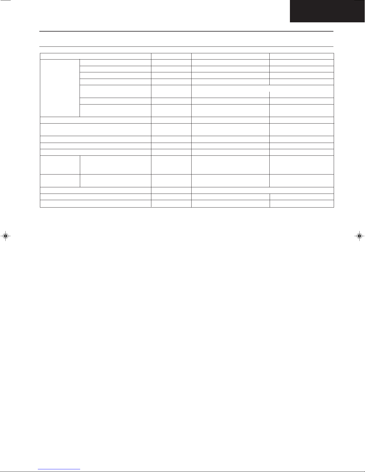
Dimensions
CS-C181K / CS-C241K
<Top View>
Air outlet direction
Left piping hole
Air intake
direction
<Front View>
290
980
Lower piping hole
Installation plate hooks
Drain ports
165
195
Approx
2,100
<Side View>
48.5
60
Remote control transmitter
Right piping hole
52
59
6
142
Relative position between the indoor unit and the installation plate <Front View>
(39)
Installation plate
Indoor unit external
dimensions line
7
276
7
(59.5)
Left piping hole
Unit : mm
Gas side Liquid side
55
Approx. 706
Slot (2 places)
892
561
100 100
Arrow
(Ø 70)
Centre
piping hole
350
Arrow
(335.5)
Installation plate positioning gauge
(Ø 70)
– 9 –
Slot (2 places)
(49)
(165)
Right piping hole
(Ø 70)
13.5
57
16
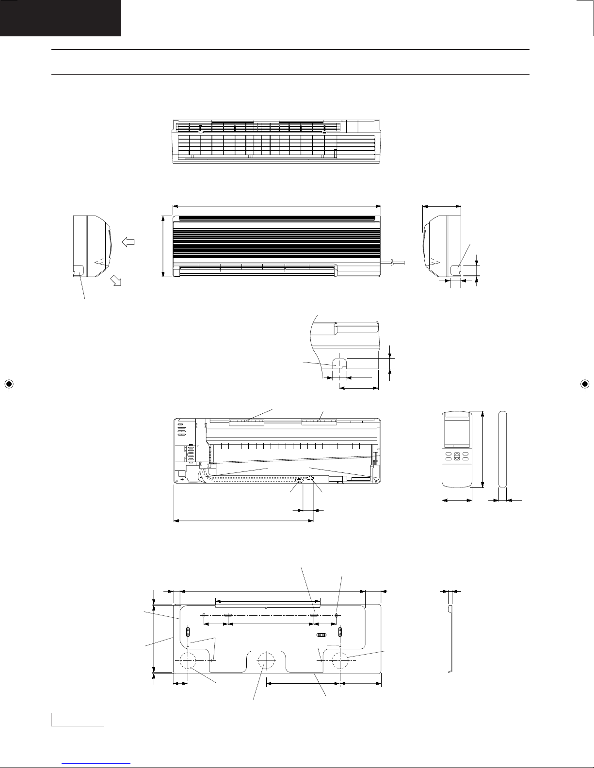
Dimensions
CU-C181K / CU-C241K
Required space for installation
10cm
10cm
Air intake direction
CS-C181KE
56.3800
35
70cm
Anchor bolt pitch 280 x 570
Air outlet direction Slots (12 x 17) Four places
663
685
Unit : mm
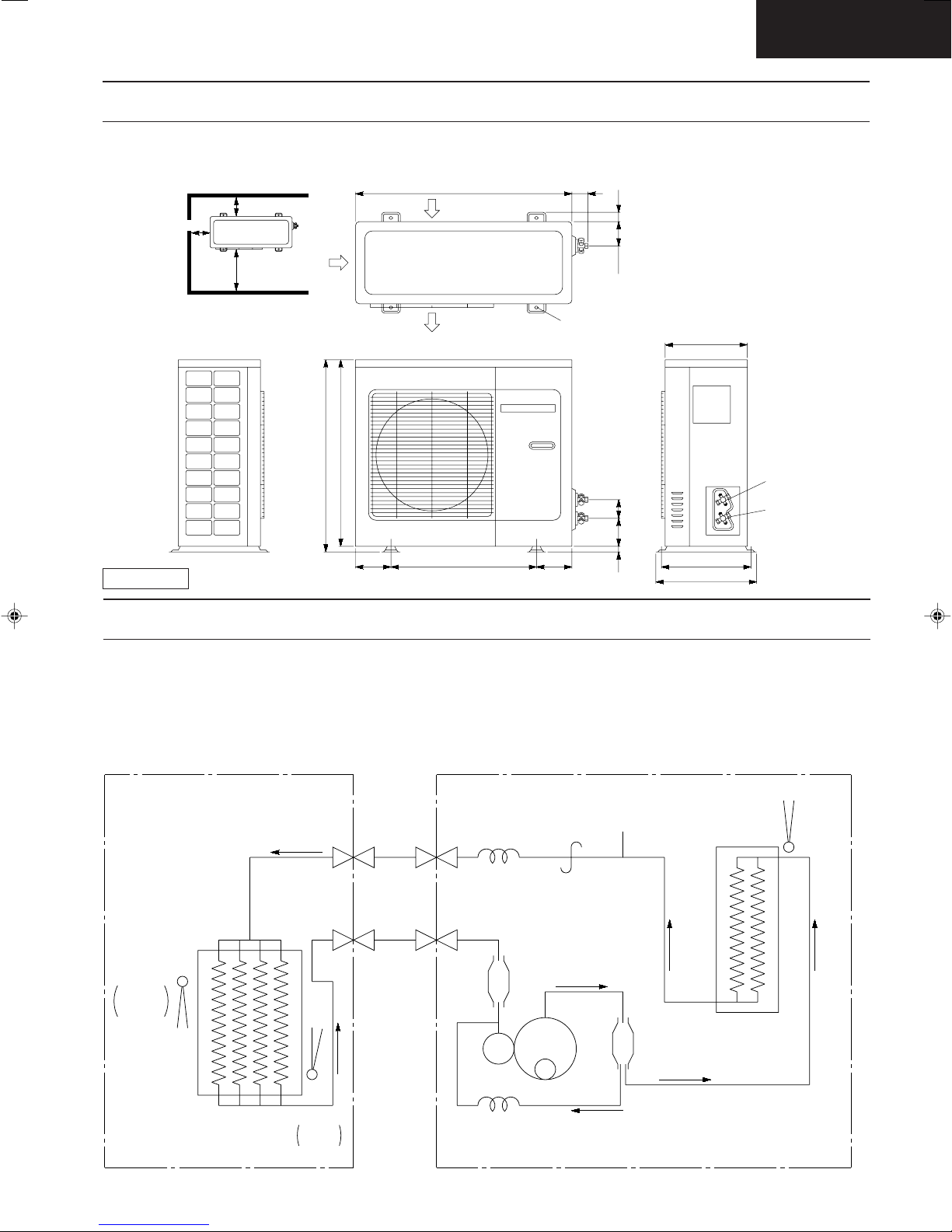
Refrigeration Cycle Diagram
CS/CU-C181K
CS/CU-C241K
106.5
300
3-way valve at
liquid side
7577.5
130130 540
22
330
370
3-way valve at
gas side
INDOOR UNIT OUTDOOR UNIT
HEAT EXCHANGER
(EVAPORATOR)
SENSOR
INTAKE
AIR
TEMP.
SENSOR
PIPE
TEMP.
LIQUID SIDE
3-WAY VALVE
GAS SIDE
3-WAY VALVE
CAPILLARY TUBE
ACCUMULATOR (SUB)
(CU-C241K ONLY)
COMPRESSOR
CAPILLARY TUBE
– 10 –
PROCESS TUBE
STRAINER
OIL
SEPARATOR
ONLY OIL
THERMOSTAT
HEAT EXCHANGER
(CONDENSER)
CS-C181KE
22
11
6C
"C"
FUSE
3.15A
RY-C
RECEIVER &
P.C.B.
SINGLE PHASE
AC 220-240V
50Hz
RY-H
TRANS-
FORMER
THERMAL
FUSE
(113°C)
(102°C)
FUSE
THERMAL
ZNR1
FAN
MOTOR
POWER SWITCH
ELECTRONIC CONTROLLER
Indicates the electronic control unit.
Indicates the number of core wires. (Example:6C=6 core wires).
COMP
J9790188 CS/CU-C181KH/C241KH
FAN
MOTOR
RY-M
SENSOR
4C
5C
STEPPING
MOTOR
INDOOR UNIT OUTDOOR UNIT
WIRELESS
REMOTE CONTROL
TRANSMITTER
3.15A
FUSE
ZNR2
SSR
MAIN
INDICATOR
C
LH
THERMOSTAT
CR2
CR1
CR3
C181KH06.DWG
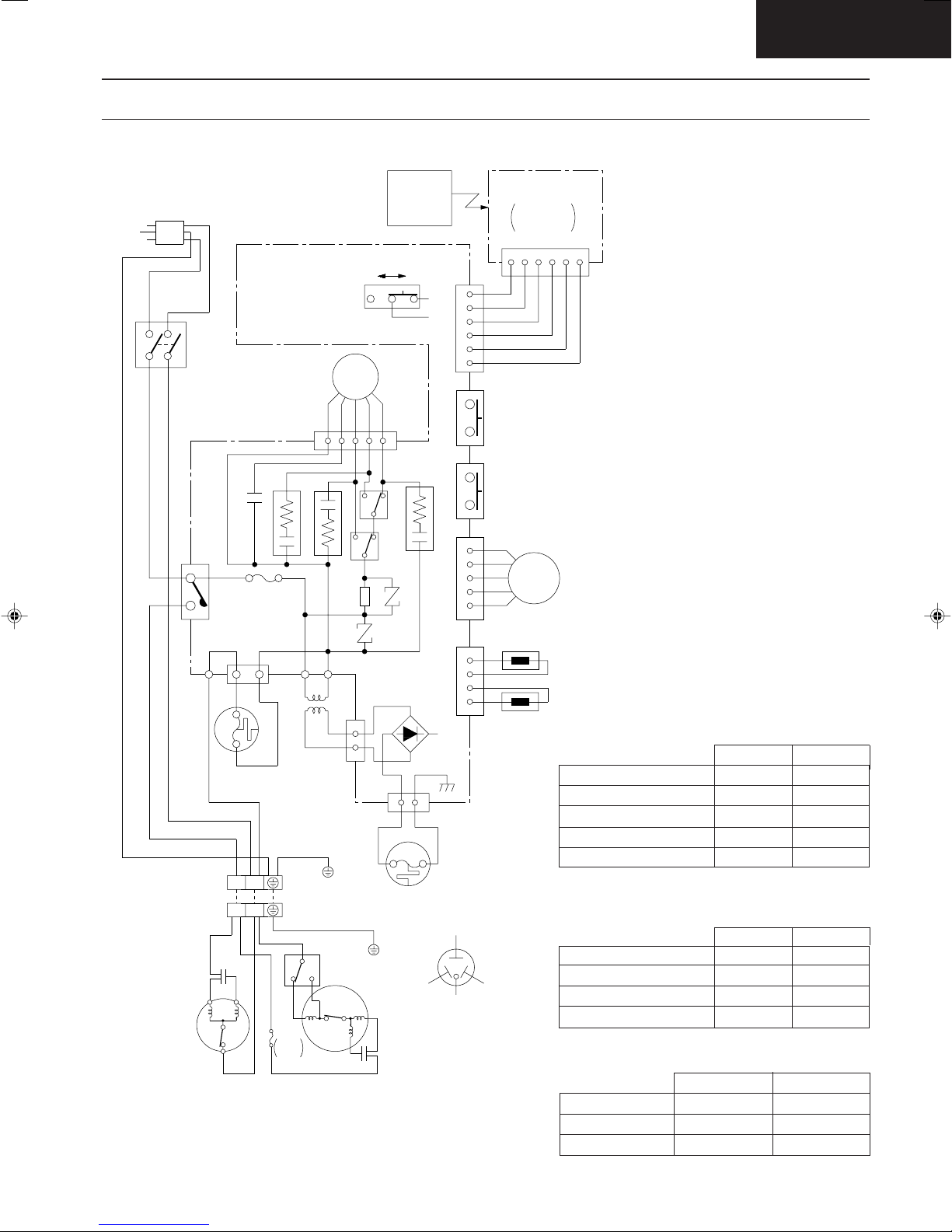
Block Diagram
CS-C181KE / CU-C181KE
CS-C241KE / CU-C241KE
– 11 –
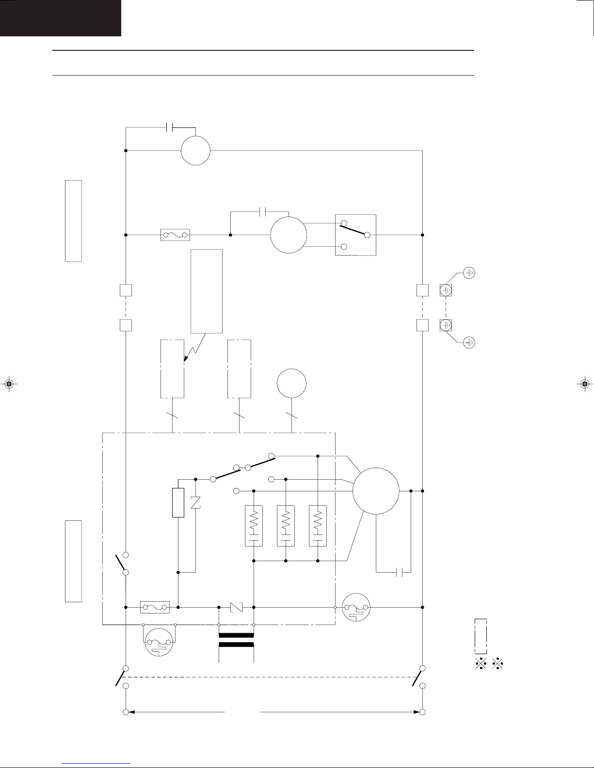
Wiring Diagram
CS-C181KE / CU-C181KE
CS-C241KE / CU-C241KE
220-240V, 50Hz
POWER SUPPLY CORD
BRW
YEL/GRN
2
13
MAIN SW
BRW
BLU
4
WHT
RY-C
P
WHT
L
WHT
BLK
YEL/GRN
INDOOR UNIT
TERMINAL
OUTDOOR UNIT
TERMINAL
BLU
COMPRESSOR
ELECTRONIC CONTROLLER
CAPACITOR
(T 3.15A L 250V)
CN-FUSE 1
AC (WHT)
THERMAL
FUSE
(113°C)
12
21
BLU
CAPACITOR
RED
YEL
CN-FM(GRN)
CR2
FUSE
T(BLK) T(BLK)
TRANSFORMER
WHT
YEL/GRN
YEL
BLU
HL
ORG BRW
FUSE
T3.15A
L250V
BLU
CR1
BLK
YEL/GRN
C
BLU
1
BLK
RED
RED
THERMOSTAT
CONTROL No.
BA
FAN
MOTOR
RED
YEL
BRW
35
7
SSR
ZNR1
CN-T(WHT)
FAN MOTOR
RED
CAPACITOR
WIRELESS
REMOTE
CONTROL
REMOTE
ORG
9
RY-M
CR3
RY-H
ZNR2
13
RED RED
BLU
CN-FUSE(BLU)
THERMAL
FUSE
(102°C)
(BLU) (RED)
TRADE MARK
COMPRESSOR TERMINAL
1
2
3
4
5
6
CN-DISP(WHT)
123454321
CN-STM(GRN) CN-TH(YEL)
YELLOW
(YEL)
ELECTRONIC
CONTROLLER
RECEIVER
+
DISPLAY LAMP
CN-DISP (WHT)
654
WHT
WHT
WHT
WHT
WHT
WHT
PUMP DOWN SW
(TEST RUN)
AUTO SW
BRW
RED
MOTOR
ORG
LOUVER
YEL
PNK
SENSOR
(AIR TEMP.)
SENSOR
(PIPE TEMP.)
REDBLUE
J9890708
CS/CU-C181KE
C181KE07.DWG
CS-C181KE
23 1
REMARKS:
BLU : BLUE
BRW : BROWN
BLK : BLACK
WHT : WHITE
RED : RED
ORG : ORANGE
PNK : PINK
YEL/GRN : YELLOW/
GREEN
GRY : GRAY
Resistance of Indoor Fan Motor Windings
CS-C181KE
CONNECTION
YELLOW - BLUE
YELLOW - BROWN
BROWN - ORANGE
ORANGE - RED
CWA92270 (Ω)
357.0
41.7
63.1
249.6
Resistance of Outdoor Fan Motor Windings
CU-C181KE
CONNECTION
BLUE - BROWN
BROWN - ORANGE
RED - BROWN
CWA92272 (Ω)
79.5
65.1
70.8
Resistance of Compressor Windings
CU-C181KE
CONNECTION
C-R
C-S
2JS350D3AA02 (Ω)
0.980
3.929
CS-C241KE
CWA92287 (Ω)
CU-C241KE
CWA92271 (Ω)
CU-C241KE
2JS464D3AA02 (Ω)
0.888
2.328
176.0
70.4
71.7
148.7
46.8
64.6
73.7
– 12 –
CS-C181KE
Operation Details
1) Cooling Mode Operation
Cooling in operation according to Remote Control setting.
Time Delay Safety Control (3 minutes)
• When the compressor is stopped by Power Switch, Remote Control or there is a power failure, it restarts after 3
minutes when the Power Switch, Remote Control is turned ON or the power supply is resumed.
• When the setting temperature is reached during cooling operation, the compressor stops and it will not start for 3
minutes.
7 minutes Time Saved Control
• The compressor will start automatically if it has stopped for 7 minutes even if the room temperature is below the
compressor ON temperature.
Anti-Freezing Control
• If the temperature of the indoor heat exchanger
falls continously below 2°C for 4 minutes, the
compressor turns off to protect the indoor heat
exchanger from freezing. The fan speed setting
remains the same.
• Compressor recommences when the indoor heat
exchanger temperature rises to 10°C (Recovery).
* 3 minutes waiting of Time Delay Safety Control
is valid for Cooling Operation.
Indoor Heat
Exchanger
Temperature
(°C)
10
2
Recovery
4 min
Compressor OFF
– 13 –
 Loading...