

Panasonic CS-A73KE, CS-A93KE, CU-A73KE, CU-A123KE, CU-A93KE Service Manual
...
ORDER NO. MAC9902015C2
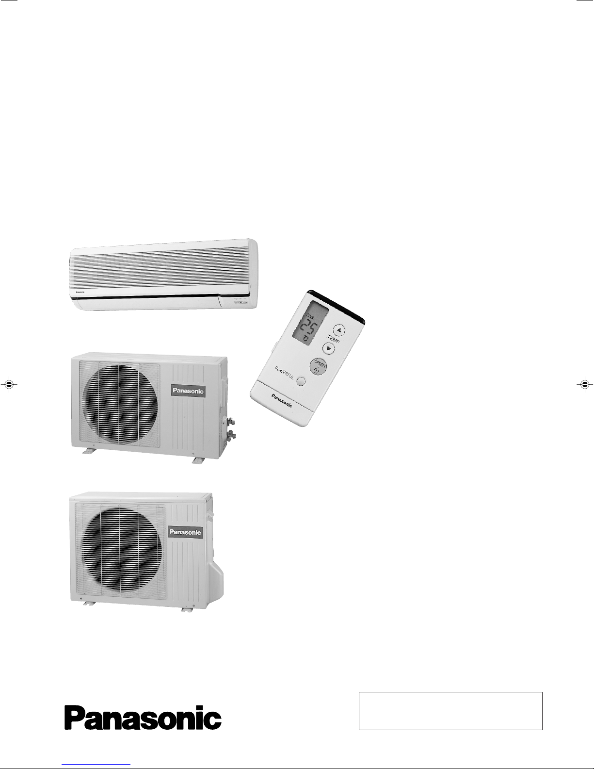
Service Manual
Room Air Conditioners
CS-A73KE / CU-A73KE
CS-A93KE / CU-A93KE
CS-A123KE / CU-A123KE
Contents
● Features ..........................................................1
● Functions ...................................................2 – 4
● Product Specifications .............................5 – 10
● Dimensions ............................................11 – 12
● Refrigeration Cycle Diagram .........................13
● Block Diagram ...............................................14
● Wiring Diagram .............................................. 15
● Operation Details ...................................16 – 30
● Installation Information ..........................31 – 32
● 2-way, 3-way Valves..............................33 – 39
● Servicing Information .............................40 – 42
● Troubleshooting Guide ..........................43 – 44
● Technical Data.......................................45 – 48
● Exploded View ...................................49, 51, 53
● Replacement Parts List .....................50, 52, 54
● Electronic Parts List ....................................... 55
1999 Matsushita Air-Conditioning Corp. Sdn. Bhd.
(183914D)
All rights reserved. Unauthorized copying and distribution is a violation of law.

CS-A73KE
WARNING
!!
!
This service information is designed for experienced repair technicians only and is not designed for use by the general public. It does not contain
warnings or cautions to advise non-technical individuals of potential dangers in attempting to service a product. Products powered by electricity
should be serviced or repaired only by experienced professional technicians. Any attempt to service or repair the product or products dealt with
in this service information by anyone else could result in serious injury or death.
!!
PRECAUTION OF LOW TEMPERATURE
!
!!
In order to avoid frostbite, be assured of no refrigerant leakage during the installation or repairing of refrigeration circuit.
!!
Features
• High Efficiency
• Compact Design
• Comfort Enviroment
– 8 hours of sleep mode operation
– Air purifying filter with deodorizing function
to reduce dust, smoke and odours.
• Random Auto Restart
– Auto restart at randomly after power failure
• Removable and Washable
Front Panel
• Quality Improvement
– Gas leakage protection
– Prevent compressor reverse rotation
– 2-stage OLP to protect compressor
• Service Improvement
– Easy fan motor replacement procedure
• Operation Improvement
– Economy mode to reduce electrical power
consumption.
– Powerful mode to reaches the desired room
temperature quickly.
• Long Installation Piping
– CS/CU–A73KE, CS/CU–A93KE, long piping up to 10
meter.
– CS/CU–A123KE, long piping up to 15 meter.
– 1 –
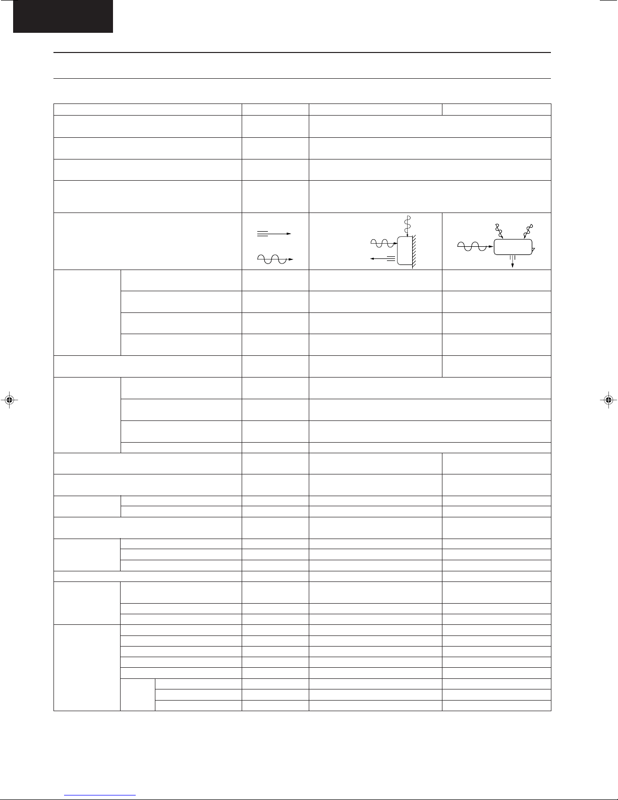
Functions
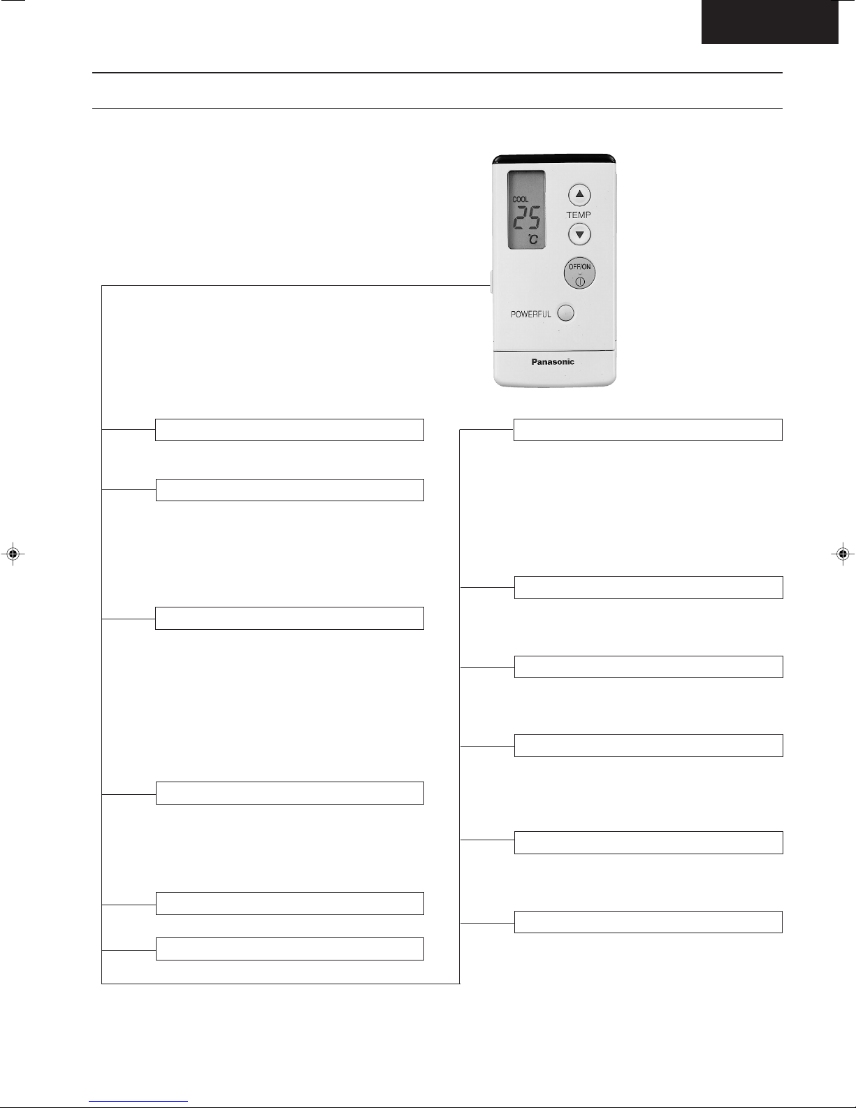
Remote Control
CS-A73KE
OFF / ON I
MODE
FAN SPEED
AIR SWING
Operation OFF / ON
Operation Mode Selection
• AUTO Automatic Operation Mode
• HEAT Heating Operation Mode
• COOL Cooling Operation Mode
• DRY Soft Dry Operation Mode
Indoor Fan Speed Selection
• h j k Low Speed
l
• h j k Medium Speed
lll
• h j k High Speed
lllll
• AUTO FAN Automatic Fan Speed
Airflow Direction Control
• AUTO Automatic Airflow Direction
Control
• MANUAL Airflow Direction Manual Control
TEMP.
ON-TIMER
OFF-TIMER
TIMER
SET
CANCEL
CLOCK
Room Temperature Setting
• Temperature Setting (16°C to 30°C)
• Automatic Operation
8 HI
a
a
a
9 Lo
Operation with 2°C higher than
standard temperature.
Operation with standard
temperature.
Operation with 2°C lower than
standard temperature.
Timer Operation Selection
• 24-hour, OFF / ON Real Timer Setting.
Time / Timer Setting
• Hours and minutes setting.
Timer Operation Set / Cancel
• ON Timer and OFF Timer setting and
cancellation.
Clock Setting
• Current time setting.
POWERFUL
ECONOMY
Powerful Mode Operation OFF/ON
Economy Mode Operation OFF/ON
– 2 –
SLEEP
Sleep Mode Operation OFF / ON
CS-A73KE
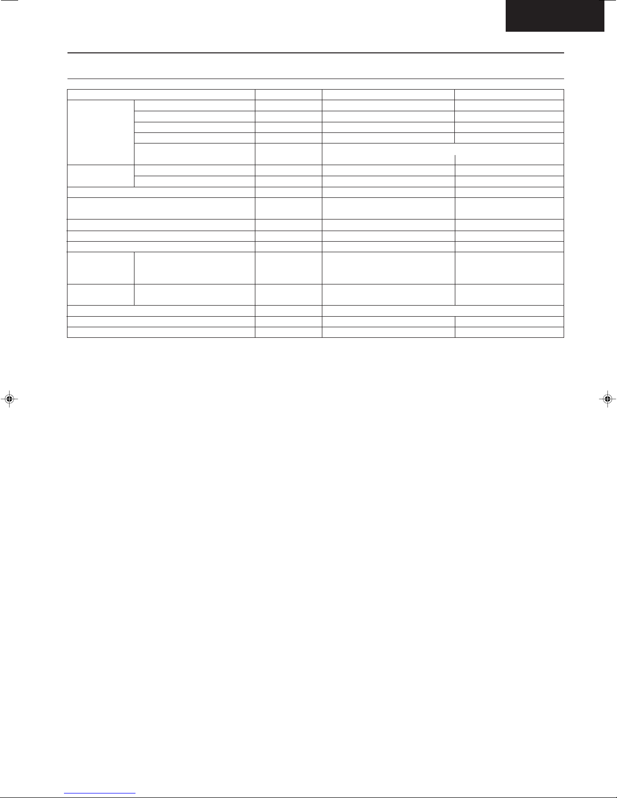
Functions
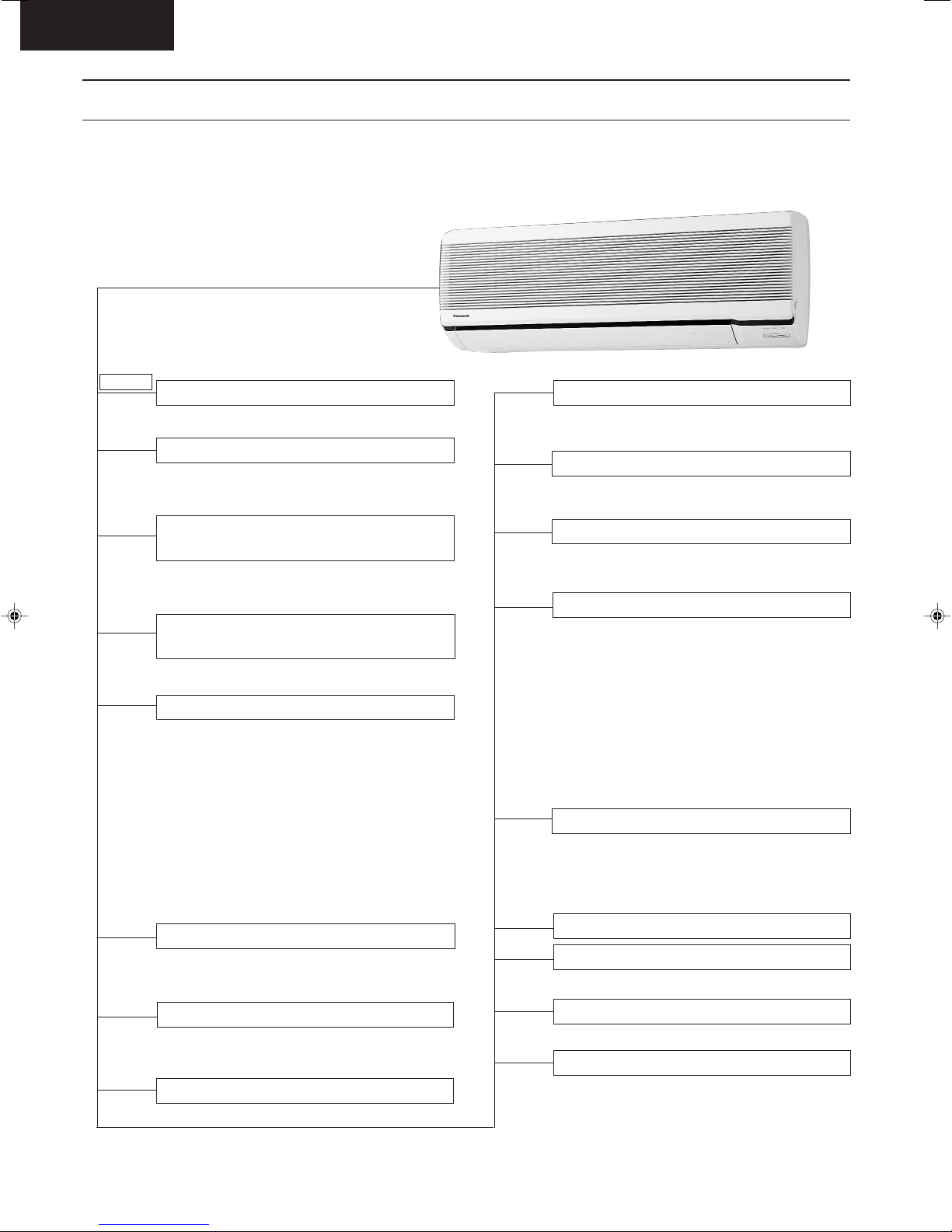
Indoor Unit
POWER I
AUTO
OFF / ON
TEST RUN
OFF / ON
Power Switch OFF / ON
Auto Operation Button
• Used when the remote control cannot be
used.
Remote Control Signal Receiving
Sound
• It can be controlled by pressing Auto
Operation Button for 10 seconds.
Operation Test Running / Pump
Down Switch
• Used when test running or servicing.
Operation Indication Lamps (LED)
• POWER (Red)...... Lights up in operation,
blinks in Automatic
Operation Mode judging
• SLEEP (Orange)..... Lights up in Sleep
Mode Operation
• TIMER (Orange)..... Lights up in Timer
Setting
• POWERFUL
• ECONOMY
(Orange).....
(Green).....
Lights up in Powerful
Mode Operation
Lights up in Economy
Mode Operation
Operation Mode
• Heating, Cooling, Soft Dry and
Automatic Mode.
Random Auto Restart Control
• Operation is restarted randomly after power
failure at previous setting mode.
Anti-Freezing Control
• Anti-Freezing control for indoor heat
exchanger. (Cooling and Soft Dry)
Sleep Mode Auto Control
• Indoor Fan operates at low speed.
• Operation stops after 8 hours.
Indoor Fan Speed Control
• High, Medium and Low.
• Automatic Fan Speed Mode
– Heating : Fan speed varies from Me →
SLo in accordance with indoor
heat exchanger.
– Cooling : Fan rotates at Hi and Me
speed. Deodorizing control is
available.
– Soft Dry : Fan rotates at SLo speed.
Deodorizing control is available.
Airflow Direction Control
• Automatic air swing and manual adjusted
by remote control for vertical airflow.
• Manually adjusted by hand for horizontal
airflow.
Starting Current Control
Time Delay Safety Control
• Restarting is inhibited for appro. 3 minutes.
Powerful Operation
• Reaches the desired room temperature
quickly.
Economy Operation
• To reduce electrical power consumption.
– 3 –
7 Minutes Time Save Control
• Cooling Operation only.
Hot-Start Control
• The indoor fan remain stop until the indoor
heat exchanger temperature reaches 30°C
• The indoor fan will operate at SLo and Lo
when indoor heat exchanger temperature
reaches 30°C - 39°C
–
Functions
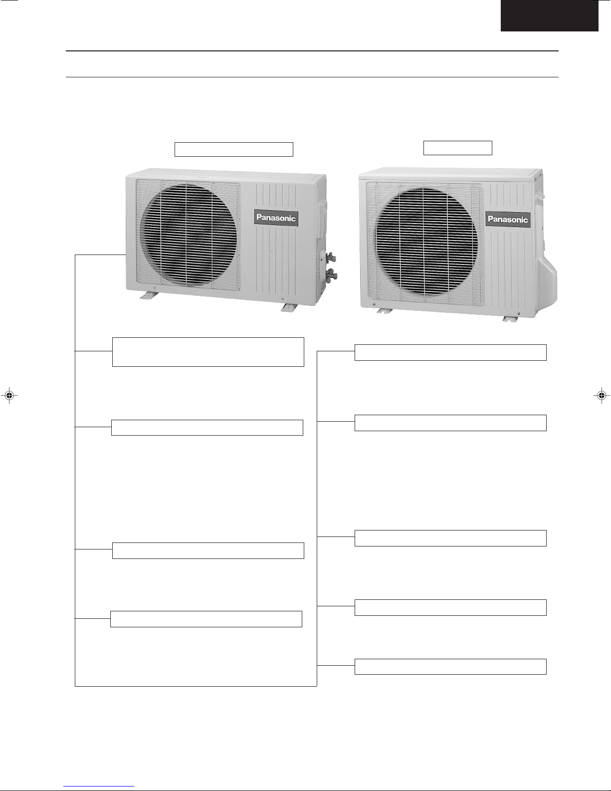
Outdoor Unit
CS-A73KE
CU-A73KE, CU-A93KE
Compressor Reverse Rotation
Protection Control
• To protect compressor from reverse
rotation when there is a instantaneous
power failure.
Overload Protector
• 2-Stage OLP to protect the compressor.
Overload Protector will trip when
– Temperature of compressor increases to
120°C.
– High temperature or high current flows to
compressor.
(Refer circuit diagram for OLP
characteristic)
60 Secs. Forced Operation Control
• Once the compressor is activated, it does
not stop within the first 60 secs. However, it
stops immediately with remote control stop
signal.
Outdoor Fan Operation Control
•
Inner protector.
CU-A123KE
Deice Control
• To prevent frosting at outdoor heat
exchanger. (Only for Heating Operation)
•
Temperature of outdoor heat exchanger is
sensed by TRS (Thermal Reed Switch).
Overload Protection Control
• Outdoor fan stops when indoor heat
exchanger temperature rises to 51°C and
above, and restarts when the indoor heat
exchanger temperature drops to 49°C and
below.
• Compressor stop when indoor heat exchanger temperature reaches 65°C or
above. (Heating Operation Only)
Compressor Protection Control
• If the outdoor fan motor is not running after
compressor starts for 50 secs., compressor
will stop. (Cooling and Soft Dry Operation
only).
4-Way Valve Control
• When the unit is switched to "OFF" during
Heating Operation, 4-way valve stays at
Heating position for 5 minutes.
Outdoor Fan Motor Control
– 4 –

CS-A73KE
Product Specifications
Cooling Capacity
Heating Capacity
Moisture Removal
Power Source
Airflow Method
Air Volume
Noise Level
Electrical
Data
Piping Connection Port
(Flare piping)
Pipe Size
(Flare piping)
Drain
Hose
Power Cord Length
Dimensions
Net Weight
Compressor
Air Circulation
Indoor Air (Lo)
Indoor Air (Me)
Indoor Air (Hi)
Outdoor Air
Input
Running Current
COP
Starting Current
Inner diameter
Length
Number of core-wire
Motor Type
Rated Output
Motor Type
Fan Low
Speed Medium
Height
Width
Depth
Type
Type
Material
Input
Rated Output
High
Unit
kW
Btu/h
kW
Btu/h
s/h
Pint/h
Phase
V
Cycle
OUTLET
INTAKE
3
m
/min (cfm)
3
/min (cfm)
m
m3/min (cfm)
m3/min (cfm)
dB (A)
W
A
W/W
A
inch
inch
inch
inch
mm
m
m
inch (mm)
inch (mm)
inch (mm)
lb (kg)
W
W
W
rpm
rpm
rpm
CS-A73KE
2.20 - 2.10
7,500 - 7,200
2.45 - 2.40
8,360 - 8,200
1.4
3.0
Single
230 - 220
50
SIDE VIEW
Cooling ; 5.9 (206) - 5.7 (200)
Heating ; 6.7 (238) - 6.6 (233)
Cooling ; 6.7 (237) - 6.4 (227)
Heating ; 7.6 (269) - 7.5 (265)
Cooling ; 7.5 (260) - 7.2 (250)
Heating ; 8.5 (300) - 8.4 (300)
–
Cooling ; High 34/33, Low 29/27
Heating ; High 36/35, Low 30/28
Cooling ; 700 - 680
Heating ; 640 - 600
Cooling ; 3.6 - 3.5
Heating ; 3.4 - 3.2
Cooling ; 3.14 - 3.09
Heating ; 3.83 - 4.00
15.5
G ; Half Union 3/8"
L ; Half Union 1/4"
G (gas side) ; 3/8"
L (liquid side) ; 1/4"
12
0.7
2.0
2
3 (1.0 mm
10-31/32 (279)
31-15/32 (799)
7-15/32 (190)
20 (9.0)
Cross-flow Fan
AS + Glass Fiber 30%
Induction (4-pole)
29.0 - 27.0
835 - 810
945 - 920
1055 - 1030
)
–
–
–
10
CU-A73KE
TOP VIEW
–
–
–
27.8 (981) - 26.8 (946)
Cooling ; High 47/45
Heating ; High 49/47
G ; 3-way valve 3/8"
L ; 2-way valve 1/4"
G (gas side) ; 3/8"
L (liquid side) ; 1/4"
–
–
–
–
18-29/32 (480)
30-23/32 (780)
9-21/32 (245)
64 (29.0)
Rotary (1 cylinder)
rolling piston type
Induction (2-pole)
600
Propeller Fan
AES + Glass Fiber 12%
Induction (6-pole)
65.8 - 57.5
20
–
–
730 - 705
– 5 –

Product Specifications
CS-A73KE
Unit
Heat
Exchanger
Refrigerant Control Device
Refrigeration Oil
Refrigerant (R-22)
Thermostat
Protection Device
Capillary Tube
Air Filter
Capacity Control
Compressor Capacitor
Fan Motor Capacitor
• Specifications are subject to change without notice for further improvement.
Description
Tube material
Fin material
Fin Type
Row / Stage
FPI
Size (W × H × L)
Length
Flow Rate
Inner Diameter
Material
Style
mm
(c.c)
g (oz)
mm
s/min
mm
µF, VAC
µF, VAC
CS-A73KE
Evaporator
Copper
Aluminium
Slit Fin
(Plate fin configuration, forced draft)
2 × 14
18
614 × 294 × 25.4
–
–
–
Electronic Control
–
–
–
–
P.P.
Honeycomb
Capillary Tube
–
1.5 µF, 400VAC
Cooling ;850, Heating ;360
Cooling ;4.5, Heating ;10.5
Cooling ;1.1, Heating ;1.3
CU-A73KE
Condenser
Copper
Aluminium
Louver Fin
1 × 18
19
856 × 457.2 × 22
Capillary Tube
SUNISO 4GDID or
ATMOS M60 (290)
815 (28.8)
–
Overload Protector
–
15 µF, 440VAC
1.2 µF, 400VAC
– 6 –

CS-A73KE
Product Specifications
Cooling Capacity
Heating Capacity
Moisture Removal
Power Source
Airflow Method
Air Volume
Noise Level
Electrical
Data
Piping Connection Port
(Flare piping)
Pipe Size
(Flare piping)
Drain
Hose
Power Cord Length
Dimensions
Net Weight
Compressor
Air Circulation
Indoor Air (Lo)
Indoor Air (Me)
Indoor Air (Hi)
Outdoor Air
Input
Running Current
COP
Starting Current
Inner diameter
Length
Number of core-wire
Motor Type
Rated Output
Motor Type
Fan Low
Speed Medium
Height
Width
Depth
Type
Type
Material
Input
Rated Output
High
Unit
kW
Btu/h
kW
Btu/h
s/h
Pint/h
Phase
V
Cycle
OUTLET
INTAKE
3
/min (cfm)
m
3
m
/min (cfm)
3
m
/min (cfm)
m3/min (cfm)
dB (A)
W
A
W/W
A
inch
inch
inch
inch
mm
m
m
inch (mm)
inch (mm)
inch (mm)
lb (kg)
W
W
W
rpm
rpm
rpm
CS-A93KE
2.80 - 2.70
9,550 - 9,200
3.40 - 3.30
11,590 - 11,250
1.6
3.4
Single
230 - 220
50
SIDE VIEW
Cooling ; 6.4 (226) - 5.9 (209)
Heating ; 6.8 (240) - 6.5 (228)
Cooling ; 7.6 (269) - 7.1 (251)
Heating ; 8.1 (286) - 7.7 (273)
Cooling ; 9.2 (320) - 8.9 (310)
Heating ; 9.8 (350) - 9.7 (340)
–
Cooling ; High 39/38, Low 29/28
Heating ; High 39/39, Low 30/28
Cooling ; 980 - 950
Heating ; 885 - 870
Cooling ; 4.6 - 4.6
Heating ; 4.2 - 4.2
Cooling ; 2.86 - 2.84
Heating ; 3.84 - 3.79
22
G ; Half Union 3/8"
L ; Half Union 1/4"
G (gas side) ; 3/8"
L (liquid side) ; 1/4"
12
0.7
2.0
14
2
)
–
–
–
3 (1.0 mm
10-31/32 (279)
31-15/32 (799)
7-15/32 (190)
20 (9.0)
Cross-flow Fan
AS + Glass Fiber 30%
Induction (4-pole)
37.0 - 34.0
865 -810
1030 -970
1245 - 1215
CU-A93KE
TOP VIEW
–
–
–
27.8 (981) - 26.8 (946)
Cooling ; High 49/48
Heating ; High 49/47
G ; 3-way valve 3/8"
L ; 2-way valve 1/4"
G (gas side) ; 3/8"
L (liquid side) ; 1/4"
–
–
–
–
18-29/32 (480)
30-23/32 (780)
9-21/32 (245)
71 (32.0)
Rotary (1 cylinder)
rolling piston type
Induction (2-pole)
800
Propeller Fan
AES + Glass Fiber 12%
Induction (6-pole)
65.8 - 57.5
20
–
–
730 - 705
– 7 –

Product Specifications
CS-A73KE
Unit
Heat
Exchanger
Refrigerant Control Device
Refrigeration Oil
Refrigeration (R-22)
Thermostat
Protection Device
Capillary Tube
Air Filter
Capacity Control
Compressor Capacitor
Fan Motor Capacitor
• Specifications are subject to change without notice for further improvement.
Description
Tube material
Fin material
Fin Type
Row / Stage
FPI
Size (W × H × L)
Length
Flow Rate
Inner Diameter
Material
Style
mm
(c.c)
g (oz)
mm
s/min
mm
µF, VAC
µF, VAC
CS-A93KE
Evaporator
Copper
Aluminium
Slit Fin
(Plate fin configuration, forced draft)
2 × 14
18
614 × 294 × 25.4
–
–
–
Electronic Control
–
–
–
–
P.P.
Honeycomb
Capillary Tube
–
1.5 µF, 400VAC
Cooling ; 1,075, Heating ; 325
Cooling ; 5.0, Heating ; 13.4
Cooling ; 1.2, Heating ; 1.4
CU-A93KE
Condenser
Copper
Aluminium
Louver Fin
1 × 18
19
856 × 457.2 × 22
Capillary Tube
SUNISO 4GDID or
ATMOS M60 (350)
935 (33.0)
–
Overload Protector
–
–
25 µF, 370VAC
1.2 µF, 400VAC
– 8 –
CS-A73KE
Product Specifications
Cooling Capacity
Heating Capacity
Moisture Removal
Power Source
Airflow Method
Air Volume
Noise Level
Electrical
Data
Piping Connection Port
(Flare piping)
Pipe Size
(Flare piping)
Drain
Hose
Power Cord Length
Dimensions
Net Weight
Compressor
Air Circulation
Indoor Air (Lo)
Indoor Air (Me)
Indoor Air (Hi)
Outdoor Air
Input
Running Current
COP
Starting Current
Inner diameter
Length
Number of core-wire
Motor Type
Rated Output
Motor Type
Fan Low
Speed Medium
Height
Width
Depth
Type
Type
Material
Input
Rated Output
High
Unit
kW
Btu/h
kW
Btu/h
s/h
Pint/h
Phase
V
Cycle
OUTLET
INTAKE
3
/min (cfm)
m
3
/min (cfm)
m
m3/min (cfm)
m3/min (cfm)
dB (A)
kW
A
W/W
A
inch
inch
inch
inch
mm
m
m
inch (mm)
inch (mm)
inch (mm)
lb (kg)
W
W
W
rpm
rpm
rpm
CS-A123KE
3.55 - 3.40
12,110 - 11,590
4.20 - 4.05
14,320 - 13,810
2.1
4.4
Single
230 - 220
50
SIDE VIEW
Cooling ; 7.5 (263) - 7.0 (247)
Heating ; 8.0 (281) -7.5 (266)
Cooling ; 8.1 (284) - 7.7 (271)
Heating ; 8.6 (303) - 8.3 (293)
Cooling ; 9.0 (320) - 8.8 (310)
Heating ; 9.6 (340) - 9.5 (340)
–
Cooling ; High 39/39, Low 34/33
Heating ; High 39/39, Low 33/32
Cooling ; 1.24 - 1.20
Heating ; 1.17 - 1.13
Cooling ; 5.6 - 5.6
Heating ; 5.2 - 5.2
Cooling ; 2.86 - 2.83
Heating ; 3.59 - 3.58
26
G ; Half Union 1/2"
L ; Half Union 1/4"
G (gas side) ; 1/2"
L (liquid side) ; 1/4"
12
0.7
2.0
3 (1.0 mm2)
10-31/32 (279)
31 -15/32 (799)
7-15/32 (190)
20 (9.0)
–
–
–
Cross-flow Fan
AS + Glass Fiber 30%
Induction (4-pole)
35.5 - 33.0
15
1060 -1000
1145 - 1100
1280 - 1260
CU-A123KE
TOP VIEW
–
–
–
35.0 (1,236) - 32.8 (1,193)
Cooling ; High 49/48
Heating ; High 49/48
G ; 3-way valve 1/2"
L ; 2-way valve 1/4"
G (gas side) ; 1/2"
L (liquid side) ; 1/4"
–
–
–
–
21-1/4 (540)
27-17/32 (699)
11-7/32 (285)
86 (39.0)
Rotary (1 cylinder)
rolling piston type
Induction (2-pole)
1,100
Propeller Fan
AES + Glass Fiber 12%
Induction (6-pole)
71.0 - 67.0
25
–
–
805 - 780
– 9 –
Product Specifications
CS-A73KE
Unit
Heat
Exchanger
Refrigerant Control Device
Refrigeration Oil
Refrigeration (R-22)
Thermostat
Protection Device
Capillary Tube
Air Filter
Capacity Control
Compressor Capacitor
Fan Motor Capacitor
• Specifications are subject to change without notice for further improvement.
Description
Tube material
Fin material
Fin Type
Row / Stage
FPI
Size (W × H × L)
Length
Flow Rate
Inner Diameter
Material
Style
mm
(c.c)
g (oz)
mm
s/min
mm
µF, VAC
µF, VAC
CS-A123KE
Evaporator
Copper
Aluminium
Slit Fin
(Plate fin configuration, forced draft)
2 × 14
21
614 × 294 × 25.4
–
–
–
Electronic Control
–
–
–
–
P.P.
Honeycomb
Capillary Tube
–
1.5 µF, 400VAC
Cooling ;1,100, Heating ;470
Cooling ;6.0, Heating ; 13.4
Cooling ; 1.3, Heating ; 1.5
CU-A123KE
Condenser
Copper
Aluminium
Louver Fin
1 × 20
18
782.9 × 508 × 22
Capillary Tube
SUNISO 4GDID or
ATMOS M60 (410)
990 (34.9)
–
Overload Protector
–
–
30 µF, 370VAC
1.5 µF, 400VAC
– 10 –
CS-A73KE
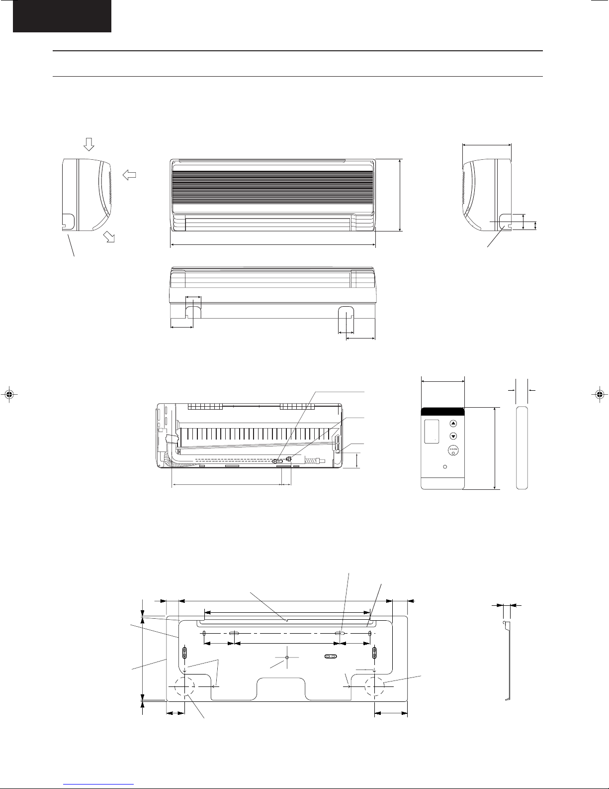
Dimensions
CS-A73KE / CS-A93KE / CS-A123KE
Left piping
hole
<Side View>
Air intake
direction
Air outlet
direction
<Front View>
60
58
799
<Back View>
60
83
GAS SIDE
279
Unit : mm
190
60
Right piping hole
<Side View>
Remote control transmitter
65
36
18
Installation
plate
Indoor unit
external
dimensions
line
LIQUID SIDE
TEMP
DRAIN PORT
65
425 48
C
POWERFUL
Relative position between the indoor unit and the installation plate <Front View>
Slot (2 places)
Slot (2 places)
(49)
Right piping hole
(99)
17.8
257.2
4
(40)
(60)
Centre notch
710
550
100 100
350
Arrow
Centre
Arrow
122
16.5
Left piping hole
– 11 –
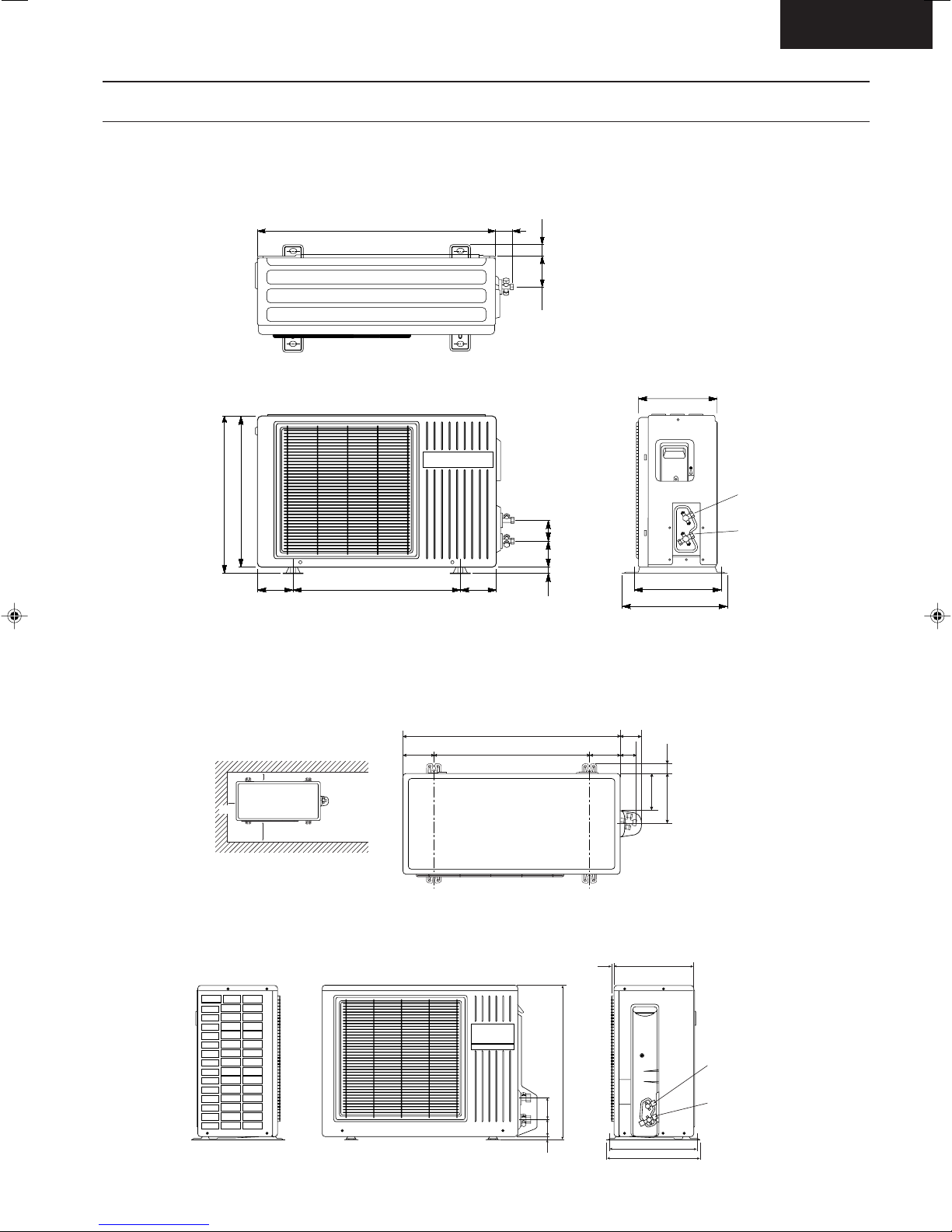
Dimensions
CU-A73KE / CU-A93KE
CS-A73KE
480
467
780 54
105105 570
27.5
93
67
77
13
245
2-way valve at
Liquid side
(High Pressure)
3-way valve at
Gas side
(Low Pressure)
280
312
CU-A123KE
Space necessary for
installation
10 cm
10 cm
100 cm
Anchor Bolt Pitch
323 x 500
699
100 500 99 (52)
7.5
540
11 67 67
69
32162
(120)
285
2-Way Valve at Liquid side
(High Pressure)
3-Way Valve at Gas side
(Low Pressure)
(323)
347
– 12 –

CS-A73KE
Refrigeration Cycle Diagram
CS-A73KE / CU-A73KE
CS-A93KE / CU-A93KE
CS-A123KE / CU-A123KE
INDOOR OUTDOOR
2-WAY
VALVE
CHECK V ALVE
C3
C1
C2
INT AKE
TEMP.
SENSOR
HEAT EXCHANGER
(EVAPORATOR)
COOLING
HEA TING
PIPE
TEMP.
SENSOR
3-WAY
VALVE
PIPE
TEMP.
SENSOR
(T .R.S)
HEAT EXCHANGER
(CONDENSER)
4-WAY VALVE
COMP.
– 13 –
Block Diagram
9C
"C"
FUSE
2A
RY-PWR
RECEIVER
P.C.B.
Indoor Unit Outdoor Unit
SINGLE PHASE
AC 220-230V
50Hz
C-FM
RY-SHI
RY-HTRANS-
FORMER
ZNR1
FAN
MOTOR
POWER SWITCH
ELECTRONIC CONTROLLER
Indicates the electronic control unit.
Indicates the number of core wires. (Example:6C=6 core wires).
MAIN
CS/CU-A73KE/A93KE
A73KEBLD.DWG
TRANSMITTER
REMOTE CONTROL
WIRELESS
MOTOR
STEPPING
5C
SENSOR
PIPE TEMP.
4C
RY-M
SSR1
ZNR1
CONTROL BOX
TEMP. FUSE
(113°C)
CR1
CR2
CR4
CR3
VALVE
4-WAY
TRS
COMP
RELAY A
B
RELAY
FM
2
1
4
3
OVERLOAD
3
4
1
2
SSR2
TEMP. SENSOR
INTAKE AIR
P.C.B.
INDICATOR
ZNR3
CT1
RY-HOT
CR5
FUSE
(102°C)
THERMAL
PROTECTOR
CR
CR
CS-A73KE
CS-A73KE / CU-A73KE
CS-A93KE / CU-A93KE
CS-A123KE / CU-A123KE
– 14 –
CS-A73KE
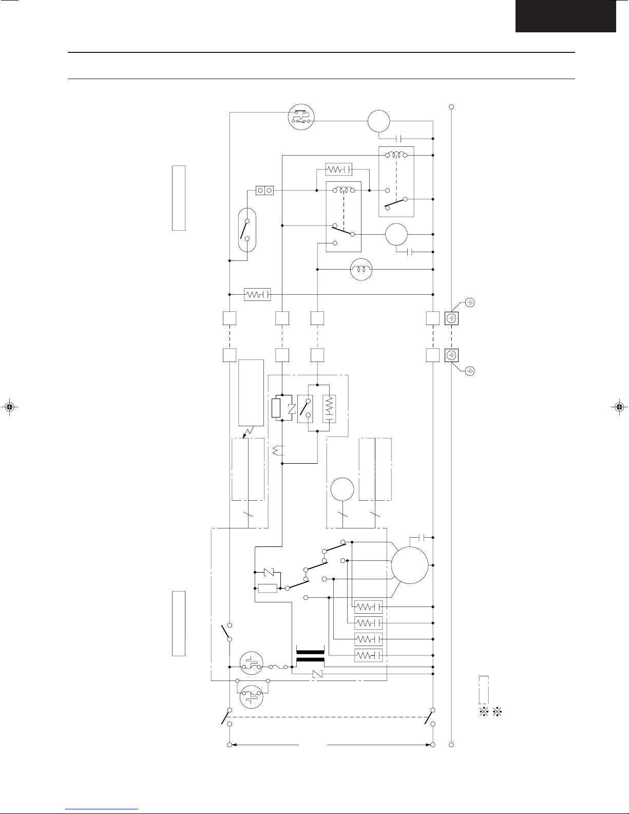
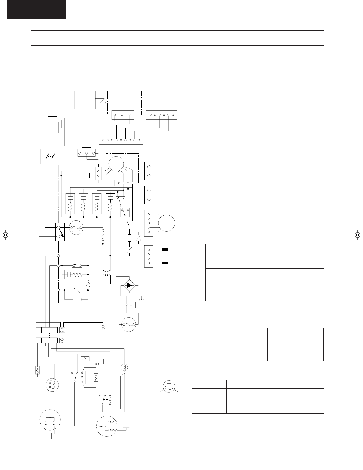
Wiring Diagram
CS-A73KE / CU-A73KE
CS-A93KE / CU-A93KE
CS-A123KE / CU-A123KE
220-240V, 50/60Hz
POWER SUPPLY CORD
Y/G
2
MAIN SW
W
BR
W
R
BL W
RB
312 4
BL
BL
CAPACIT OR
ELECTROLYTIC
1
Y
BR
4
31
421 3
GRY
P
L
B
Y/G
4
B
CR1
RY-PWR
AC (W)
HOT(R)
FM(B)
INDOOR UNIT
TERMINAL
OUTDOOR UNIT
TERMINAL
OVER LOAD
PROTECTOR
THERMAL
FUSE
(113°C)
RY-HOT
CR5
ZNR3
SSR2
BLBLBL
GRY
R
67
MAGNETIC RELAY B
WIRELESS
REMOTE
CONTROL
REMOTE
CONTROL No.
CN-C
B
R
CAPACITOR
CR2
W
TRS
BL
824
BR
W
1
234
AB
ELECTRONIC CONTROLLER
(G)
1
3
CN-FM(G)
CR4
CR3
FUSE T2A L250V
BL
BL
TRANSFORMER
CT1
ELECTRONIC
CONTROLLER
GRY
BL
CAPACITOR
ELECTROLYTIC
BL
428
B
ELECTRONIC
CONTROLLER
(RECEIVER)
CN-RCV (W)
WWW
CN-DISP(W)
FAN
MOTOR
W
R
R
76
MAGNETIC RELAY A
B
123 56
WWWWW
O
BR
7
531
RY-M
SSR1
ZNR1
THERMAL
FUSE
(102°C)
COIL
Y
RY-H
RY-SHI
ZNR2
CN-FUSE(B)
31
RR
REVERSING VAL VE
97658
1234 54321
CN-TH(Y) CN-STM(G)
DISPLAY LAMP
CN-DISP(W)
4321
PUMP DOWN SW
(TEST RUN)
AUTO SW
BR
R
FAN
O
MOTOR
Y
P
SENSOR
(INTAKE TEMP.)
SENSOR
(PIPE TEMP .)
YELLOW
BRAND MARK
COMPRESSOR TERMINAL
REMARKS:
B : BLUE
BR : BROWN
BL : BLACK
W : WHITE
R : RED
O : ORANGE
P : PINK
Y/G : YELLOW/
Resistance of Indoor Fan Motor Windings
MODEL
CONNECTION
YELLOW-BLUE
YELLOW-BROWN
BROWN-ORANGE
ORANGE-WHITE
WHITE-RED
Resistance of Outdoor Fan Motor Windings
MODEL
CONNECTION
BLUE-YELLOW
YELLOW-RED
CU-A73KE
CWA95245
260.5 Ω
446.0 Ω
Resistance of Compressor Windings
REDBLUE
MODEL
CONNECTION
C-R
C-S
CU-A73KE
2RS127D3CA04
4.023
8.803
GREEN
CS-A73KE
CWA92288
536.5 Ω
77.1 Ω
43.9 Ω
42.7 Ω
111.4 Ω
CU-A93KE
CU-A93KE
2PS174D3AA02
2.798 Ω
5.432 Ω
CS-A93KE
CWA92296
450.8 Ω
56.9 Ω
74.2 Ω
37.3 Ω
122.6 Ω
@
@
@
CU-A123KE
2KS224D5CA02
CS-A123KE
CWA92290
457.4 Ω
56.1 Ω
61.2 Ω
25.3 Ω
142.5 Ω
CU-A123KE
CWA95381
174.5 Ω
331.0 Ω
2.211 Ω
2.924 Ω
B
COMPRESSOR
R
CAPACITOR
Y
B
W
FAN MOTOR
B
CAPACITOR
R
J9990083
CS/CU-A73KE/A93KE/A123KE
A73KE07.DWG
– 15 –
CS-A73KE
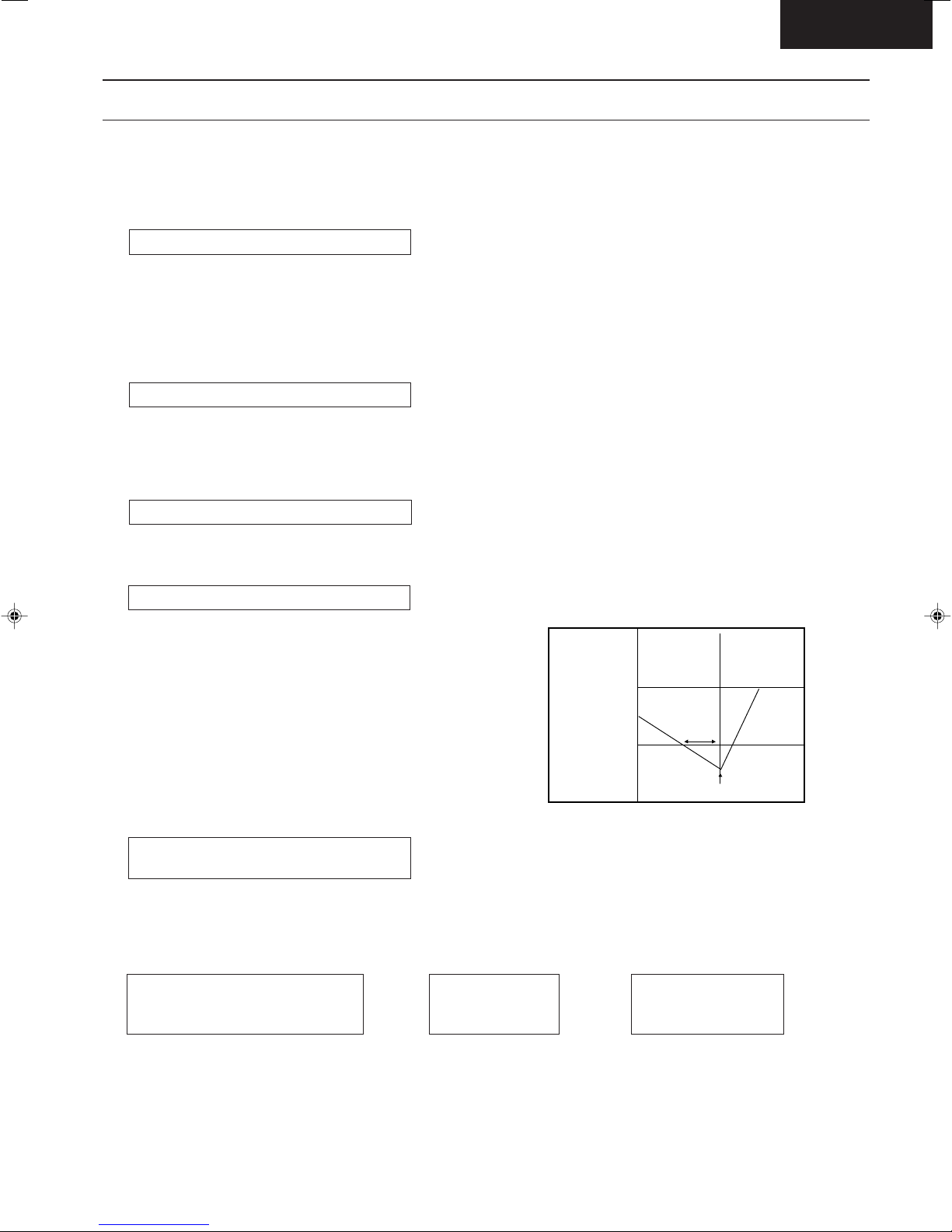
Operation Details
1) Cooling Mode Operation
Cooling in operation according to Remote Control setting.
Time Delay Safety Control (3 minutes)
• When the compressor is stopped by Power Switch or Remote Control, it restarts after 3 minutes when the Power
Switch or Remote Control is turned ON.
• When the setting temperature is reached during cooling operation, the compressor stops and it will not start for 3
minutes.
7 minutes Time Saved Control
• The compressor will start automatically if it has stopped for 7 minutes if the room temperature is between the
compressor ON temperature and OFF temperature.
Starting Current Control
• When the compressor, outdoor fan motor & indoor fan motor are simultaneously started, the indoor fan motor will
operate 1.6 second later.
Anti-Freezing Control
• If the temperature of the indoor heat exchanger
falls continously below 2°C for 4 minutes or more,
the compressor turns off to protect the indoor heat
exchanger from freezing. The fan speed setting
remains the same.
• Compressor recommences when the indoor heat
exchanger temperature rises to 10°C (Recovery).
* 3 minutes waiting of Time Delay Safety Control
is valid for Cooling Operation.
Compressor Reverse Rotation
Protection Control
• If the compressor is operating continuously for 5 minutes or longer and the temperature difference between intake
air and indoor heat exchanger is 2.5°C or less for 2 minutes, compressor will stop and restart automatically.
(Time Delay Safety Control is valid).
Indoor Heat
Exchanger
Temperature
(°C)
10
2
Recovery
4 min
Compressor OFF
•
Compressor starts for > 5 minutes
• ∆ T < 2.5°C for 2 minutes
∆ T = Intake air temperature – Indoor heat exchanger temperature
This is to protect reverse rotation of the compressor when there is a instantaneous power failure.
Compressor
➡➡
OFF
– 16 –
Compressor
restarts
(3 minutes waiting)

CS-A73KE
Operation Details
Compressor Protection Control
• After the compressor starts for 50 seconds but the outdoor fan motor is still OFF, the compressor will stop and
restart automatically. (Time Delay Safety Control is valid).
Comp. operates for 50 secs.
and
Fan Motor OFF
• If the above phenomenon is repeated for 3 times, the compressor will stops.
• The above phenomenon is reset when there is a change to heating mode or stopped by Remote Control Switch.
Automatic Fan Speed Mode
When Automatic Fan Speed is selected at Remote Control during cooling operation.
• Fan speed rotates in the range of Hi to Me.
• Deodorizing Control.
Indoor
Fan
stop stop stop
stop
40"
➡➡
.
.
.
✕
.
1
SLo SLo SLo SLo
30"
Compressor
OFF
20"
40"
30"160"
Compressor
restarts
(3 minutes waiting)
.
.
.
✕
.
2
Comp.
ON ONOFF
* 1 Fan Speed is Hi until the compressor stops (when the room temperature reaches
setting temperature).
* 2 Fan Speed is Me after the compressor restarts.
* SLo: Indoor Fan rotates at 4 second intervals at low speed.
– 17 –
 Loading...