

Panasonic CS-A18EKH, CU-A18EKH, CS-A24EKH, CU-A24EKH Service Manual
© 2005 Panasonic HA Air-Conditioning (M) Sdn Bhd
(11969-T). All rights reserved. Unauthorized copying
and distribution is a violation of law.
Order No. MAC0511090C3
Air Conditioner
CS-A18EKH CU-A18EKH
CS-A24EKH CU-A24EKH
TABLE OF CONTENTS
PAG E PAG E
1 Safety Precaution ------------------------------------------------ 3
2 Specifications ----------------------------------------------------- 5
2.1. CS-A18EKH CU-A18EKH ------------------------------- 5
2.2. CS-A24EKH CU-A24EKH ------------------------------- 7
3Features------------------------------------------------------------- 9
4 Location of Controls and Components ------------------10
4.1. Product Overview-----------------------------------------10
5Dimensions-------------------------------------------------------- 11
5.1. Indoor Unit-------------------------------------------------- 11
5.2. Outdoor Unit -----------------------------------------------12
6 Refrigeration Cycle Diagram --------------------------------13
7 Block Diagram ----------------------------------------------------14
8 Wiring Connection Diagram ---------------------------------15
9 Printed Circuit Board-------------------------------------------16
9.1. Indoor Unit (Main Printed Circuit Board) ------------16
9.2. Indoor Unit (Power Printed Circuit Board) ----------18
9.3. Outdoor Unit (Main Printed Circuit Board) ---------19
9.4. Indicator panel---------------------------------------------20
10 Installation Instruction ---------------------------------------- 21
10.1. Indoor Unit ------------------------------------------------- 22
10.2. Outdoor Unit----------------------------------------------- 25
11 Operation and Control ---------------------------------------- 27
11.1. Heating Operation --------------------------------------- 27
11.2. Cooling Operation---------------------------------------- 28
11.3. Soft Dry Operation--------------------------------------- 29
11.4. Automatic Operation ------------------------------------ 30
11.5. Operation Control ---------------------------------------- 31
11.6. Indoor Fan Speed Control ----------------------------- 37
11.7. Outdoor Fan Speed Control --------------------------- 39
11.8. Vertical Airflow Direction Control --------------------- 39
11.9. Horizontal Airflow Direction Control ----------------- 40
11.10. Powerful Operation -------------------------------------- 41
11.11. Quiet Operation------------------------------------------- 42
11.12. Timer Control---------------------------------------------- 43
11.13. Random Auto Restart Control ------------------------ 44
11.14. Remote Control Signal Receiving Sound ---------- 44

2
11.15. Auto Refresh Deo ----------------------------------------44
12 Servicing Mode -------------------------------------------------- 45
12.1. Auto OFF/ON Button ------------------------------------ 45
12.2. Remote Control Button --------------------------------- 45
12.3. Test Mode Timer Table----------------------------------46
13 Troubleshooting Guide---------------------------------------- 47
13.1. Refrigeration Cycle System --------------------------- 47
14 Disassembly and Assembly Instructions--------------- 49
14.1. Indoor Electronic Controllers, Cross Flow Fan
and Indoor Fan Motor Removal Procedures ------49
15 Technical Data---------------------------------------------------- 52
15.1. Thermostat Characteristics ---------------------------- 52
15.2. Operation Characteristics ------------------------------ 53
16 Exploded View and Replacement Parts List -----------61
16.1. Indoor Unit ------------------------------------------------- 61
16.2. Outdoor Unit ----------------------------------------------- 63
3
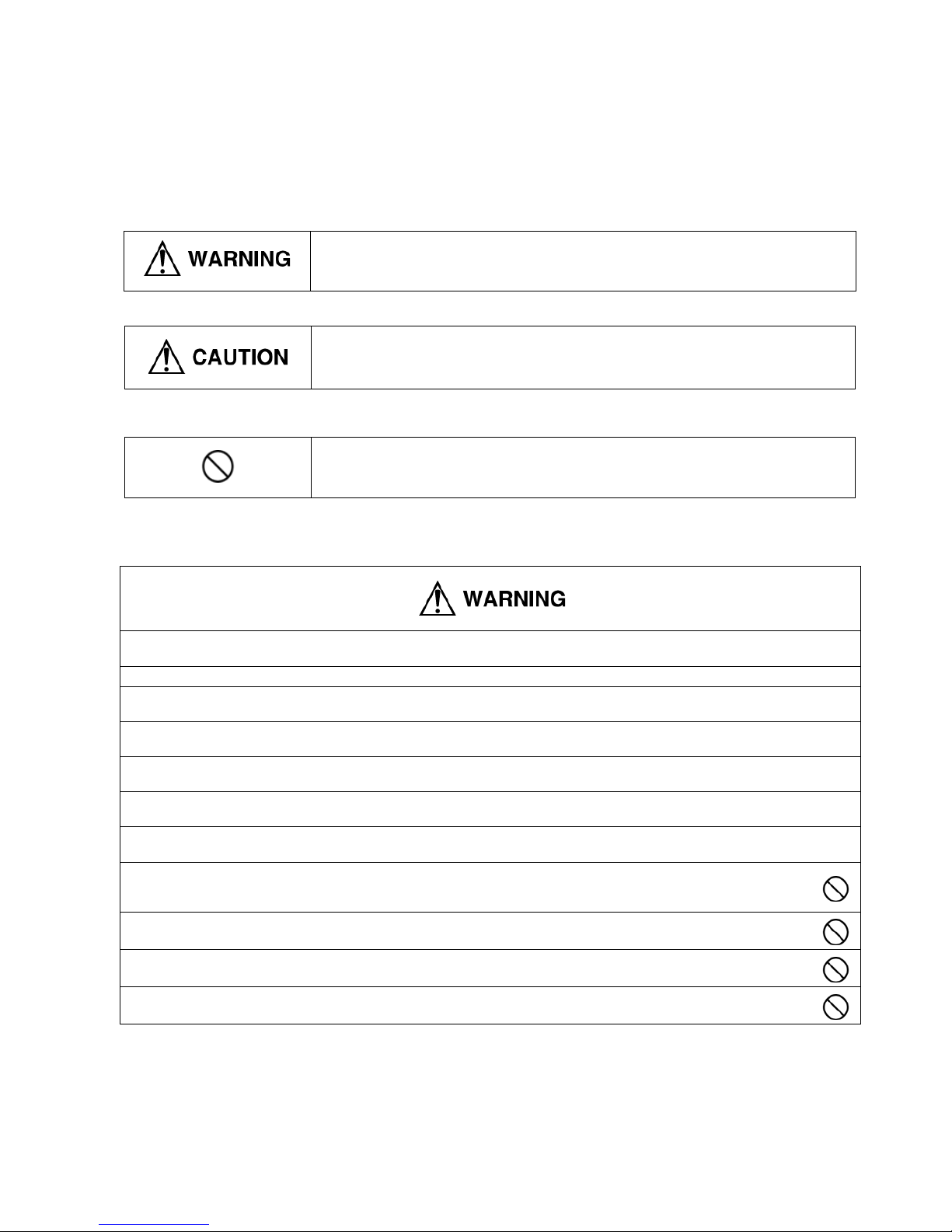
1 Safety Precaution
• Read the following “SAFETY PRECAUTIONS” carefully before perform any servicing.
• Electrical work must be installed or serviced by a licensed electrician. Be sure to use the correct rating of the power plug and
main circuit for the model installed.
• The caution items stated here must be followed because these important contents are related to safety. The meaning of each
indication used is as below. Incorrect installation or servicing due to ignoring of the instruction will cause harm or damage, and
the seriousness is classified by the following indications.
• The items to be followed are classified by the symbols:
• Carry out test running to confirm that no abnormality occurs after the servicing. Then, explain to user the operation, care and
maintenance as stated in instructions. Please remind the customer to keep the operating instructions for future reference.
This indication shows the possibility of causing death or serious injury.
This indication shows the possibility of causing injury or damage to properties.
This symbol denotes item that is PROHIBITTED from doing.
1. Engage dealer or specialist for installation and servicing. If installation or servicing done by the user is defective, it will cause water
leakage, electrical shock or fire.
2. Install according to this installation instruction strictly. If installation is defective, it will cause water leakage, electrical shock or fire.
3. Use the attached accessories parts and specified parts for installation and servicing. Otherwise, it will cause the set to fall, water leakage,
fire or electrical shock.
4. Install at a strong and firm location which is able to withstand the set's weight. If the strength is not enough or installation is not properly
done, the set will drop and cause injury.
5. For electrical work, follow the local national wiring standard, regulation and the installation instruction. An independent circuit and single
outlet must be used. If electrical circuit capacity is not enough or defect found in electrical work, it will cause electrical shock or fire.
6. Use the specified cable and connect tightly for indoor/outdoor connection. Connect tightly and clamp the cable so that no external force will
be acted on the terminal. If connection or fixing is not perfect, it will cause heat-up or fire at the connection.
7. Wire routing must be properly arranged so that control board cover is fixed properly. If control board cover is not fixed perfectly, it will cause
heat-up at connection point of terminal, fire or electrical shock.
8. When connecting the piping, do not allow air or any substances other than the specified refrigerant to enter the refrigeration
cycle. Otherwise, this may lower the capacity, cause abnormally high pressure in the refrigeration cycle, and possibly result in
explosion and injury.
9. Thickness of copper pipes used must be more than 0.8 mm. Never use copper pipes thinner than 0.8 mm.
10. It is desirable that the amount of residual oil is less than 40 mg/10 m.
11. Do not modify the length of the power supply cord or use of the extension cord, and do not share the single outlet with other
electrical appliances. Otherwise, it will cause fire or electrical shock.

4
1. The equipment must be earthed. It may cause electrical shock if grounding is not perfect.
2. Do not install the unit at place where leakage of flammable gas may occur. In case gas leaks and accumulates at surrounding of
the unit, it may cause fire.
3. Carry out drainage piping as mentioned in installation instructions. If drainage is not perfect, water may enter the room and damage the
furniture.
4. Pb free solder has a higher melting point than standard solder; typically the melting point is 50 - 70°F (30 - 40°C) higher. Please use a high
temperature soldering iron. In case of the soldering iron with temperature control, please set it to 700 ± 20°F (370 ± 10°C).Pb free solder
will tend to splash when heated too high (about 1100°F/600°C).
1. Selection of the installation location. Select an installation location which is rigid and strong enough to support or hold the unit, and select
a location for easy maintenance.
2. Power supply connection to the conditioner. Connect the power supply cord of the air conditioner to the mains using one of the following
methods.
Power supply point shall be the place where there is ease for access for the power disconnection in case of emergency.
In some countries, permanent connection of this room air conditioner to the power supply is prohibited.
1. Power supply connection to the receptacle using a power plug. Use an approved power plug with earth pin for the connection to the
socket.
2. Power supply connection to a circuit breaker for the permanent connection. Use an approved circuit breaker for the permanent
connection. It must be a double pole switch with a minimum 3.5 mm contact gap.
3. Do not release refrigerant during piping work for installation, servicing, reinstallation and during repairing a refrigeration parts. Take care of
the liquid refrigerant, it may cause frostbite.
4. Installation work. It may need two people to carry out the installation work.
5. Do not install this appliance in a laundry room or other location where water may drip from the ceiling, etc.

5
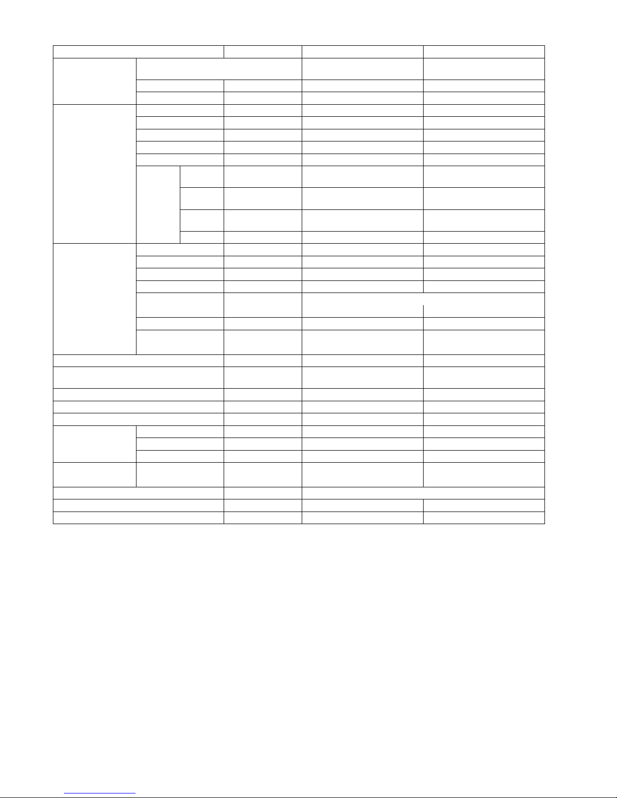
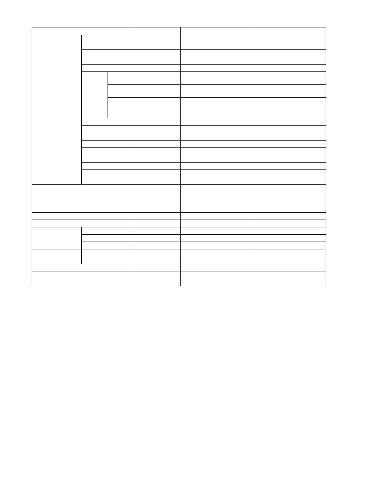
2 Specifications
2.1. CS-A18EKH CU-A18EKH
Unit CS-A18EKH CU-A18EKH
Performance Test Condition NEW JIS
Power Source (Phase, Voltage, Cycle) ø, V, Hz Single, 220 - 240, 50
Cooling Capacity kW (BTU/h) 5.40 (18,400) - 5.40 (18,400)
Heating Capacity kW (BTU/h) 5.90 (20,100) - 6.00 (20,500)
Moisture Removal l/h (Pint/h) 2.9 (6.1)
Airflow Method OUTLET
INTAKE
SIDE VIEW TOP VIEW
Air Volume Lo
m
3
/min (cfm)
Cooling; 13.0 (460) - 13.0 (460)
Heating; 14.2 (500) - 14.2 (500)
28.6 (1,010) - 32.4 (1,140)
Me
m
3
/min (cfm)
Cooling; 14.4 (510) - 14.4 (510)
Heating; 14.8 (520) - 14.8 (520)
—
Hi
m
3
/min (cfm)
Cooling; 15.3 (540) - 15.3 (540)
Heating; 16.0 (560) - 16.0 (560)
50.7 (1,790) - 52.7 (1,860)
SHi
m
3
/min (cfm)
Cooling; 15.6 (550) - 15.6 (550) —
Noise Level dB (A) Cooling; High 43 - 43, Low 38 - 38
Heating; High 42 - 42, Low 38 - 38
Cooling; High 53 - 54
Heating; High 54 - 55
Electrical Data Input Power kW Cooling; 1.68 - 1.73
Heating; 1.63 - 1.70
Running Current A Cooling; 7.8 - 7.5
Heating; 7.6 - 7.5
EER W/W (BTU/hW) Cooling; 3.21 - 3.12 (10.95 - 10.64)
COP W/W (BTU/hW) Heating; 3.62 - 3.53 (12.33 - 12.06)
Starting Current A 47.0
Piping Connection Port
(Flare piping)
inch
inch
G ; Half Union 1/2”
L ; Half Union 1/4”
G ; 3-way valve 1/2”
L ; 3-way valve 1/4”
Pipe Size
(Flare piping)
inch G ; (gas side) 1/2” G ; (gas side) 1/2”
inch L ; (liquid side) 1/4” L ; (liquid side) 1/4”
Drain
Hose
Inner diameter mm 16 —
Length mm 650 —
Power Cord Length m 1.9 —
Number of core-wire
3 (1.5 mm
2
)
—
Dimensions Height inch (mm) 10 - 13/16 (275) 29 - 17/32 (750)
Width inch (mm) 39 - 9/32 (998) 34 - 7/16 (875)
Depth inch (mm) 9 - 1/16 (230) 13 - 19/32 (345)
Net Weight lb (kg) 24 (11.0) 132 (60.0)
6
Note
• Specifications are subject to change without notice for further improvement.
Compressor Description — Rotary (1 cylinder)
rolling piston type
Motor Type — Induction (2-poles)
Rated Output kW — 1.5
Air Circulation Description Cross-flow Fan Propeller Fan
Material ASHT-18 PP
Motor Type Transistor (8-poles) Induction (6-poles)
Input W — 125.7 - 143.9
Rated Output W 30 80
Fan Speed Low rpm Cooling; 1,190 - 1,190
Heating; 1,270 - 1,270
460 - 520
Medium rpm Cooling; 1,320 - 1,320
Heating; 1,320 - 1,320
—
High rpm Cooling; 1,400 - 1,400
Heating; 1,430 - 1,430
815 - 845
SuperHigh rpm Cooling; 1,430 - 1,430 —
Heat Exchanger Description Evaporator Condenser
Tube material Copper Copper
Fin material Aluminium (Pre Coat) Aluminium
Fin Type Slit Fin Corrugated Fin
Row/Stage (Plate fin configuration, forced draft)
2 × 15 2 × 28
FPI 21 16
Size (W × H × L) mm 810 × 315 × 25.4 827.7 × 711.2 × 44
862.2
Refrigerent Control Device — Capillary Tube
Refrigeration Oil
(cm
3
)
— SUNISO 4GDID or ATMOS
M60 or ATMOS 56M (1,000)
Refrigerant (R-22) g (oz) — 1,710 (60.4)
Thermostat ——
Protection Device — Inner Protector
Capillary Tube Length mm — Cooling; 970, Heating; 820
Flow Rate l/mm — Cooling; 11.0, Heating; 27.0
Inner Diameter mm — Cooling; 1.6, Heating; 2.2
Air Filter Material
Styl e
P. P.
Honeycomb
—
Capacity Control Capillary Tube
Compressor Capacitor µF, VAC — 45 µF, 400/440VAC
Fan Motor Capacitor µF, VAC — 3.5 µF, 440VAC
Unit CS-A18EKH CU-A18EKH
7
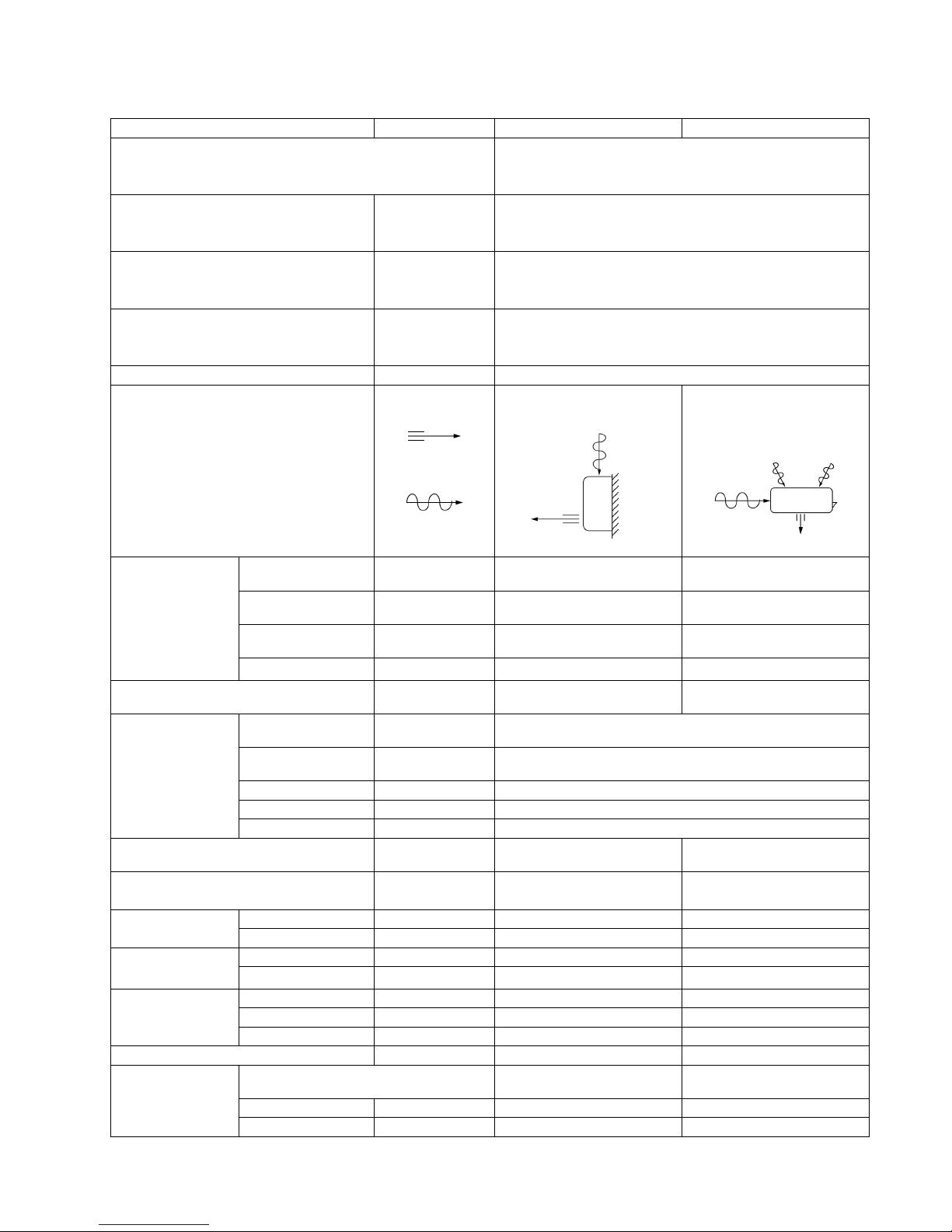
2.2. CS-A24EKH CU-A24EKH
Unit CS-A24EKH CU-A24EKH
Performance Test Condition NEW JIS
Power Source (Phase, Voltage, Cycle) ø, V, Hz Single, 220 - 240, 50
Cooling Capacity kW (BTU/h) 7.03 - 7.03 (24,000 - 24,000)
Heating Capacity kW (BTU/h) 7.80 - 7.80 (26,600 - 26,600)
Moisture Removal l/h (Pint/h) 4.0 (8.5)
Airflow Method OUTLET
INTAKE
SIDE VIEW TOP VIEW
Air Volume Lo
m
3
/min (cfm)
Cooling; 13.7 (480) - 13.7 (480)
Heating; 14.7 (520) - 14.7 (520)
28.1 (990) - 31.7 (1,120)
Me
m
3
/min (cfm)
Cooling; 15.8 (560) - 15.8 (560)
Heating; 15.8 (560) - 15.8 (560)
—
Hi
m
3
/min (cfm)
Cooling; 16.8 (590) - 16.8 (590)
Heating; 17.6 (620) - 17.6 (620)
49.7 (1,750) - 51.7 (1,830)
SHi
m
3
/min (cfm)
Cooling; 17.7 (630) - 17.7 (630) —
Noise Level dB (A) Cooling; High 47 - 47, Low 41 - 41
Heating; High 46 - 46, Low 41 - 41
Cooling; High 53 - 54
Heating; High 54 - 55
Electrical Data Input Power kW Cooling; 2.54 - 2.58
Heating; 2.53 - 2.56
Running Current A Cooling; 12.3 - 12.2
Heating; 12.2 - 12.1
EER W/W (BTU/hW) Cooling; 2.77 - 2.72 (9.45 - 9.30)
COP W/W (BTU/hW) Heating; 3.08 - 3.05 (10.51 - 10.39)
Starting Current A 67.0
Piping Connection Port
(Flare piping)
inch
inch
G ; Half Union 5/8”
L ; Half Union 1/4”
G ; 3-way valve 5/8”
L ; 3-way valve 1/4”
Pipe Size
(Flare piping)
inch G ; (gas side) 5/8” G ; (gas side) 5/8”
inch L ; (liquid side) 1/4” L ; (liquid side) 1/4”
Drain
Hose
Inner diameter mm 16 —
Length mm 650 —
Power Cord Length m 1.9 —
Number of core-wire
3 (2.5 mm
2
)
—
Dimensions Height inch (mm) 10 - 13/16 (275) 29 - 17/32 (750)
Width inch (mm) 39 - 9/32 (998) 34 - 7/16 (875)
Depth inch (mm) 9 - 1/16 (230) 13 - 19/32 (345)
Net Weight lb (kg) 26 (12.0) 139 (63.0)
Compressor Description — Rotary (1 cylinder)
rolling piston type
Motor Type — Induction (2-poles)
Rated Output kW — 2.0
8
Note
• Specifications are subject to change without notice for further improvement.
Air Circulation Description Cross-flow Fan Propeller Fan
Material ASHT-18 PP
Motor Type Transistor (8-poles) Induction (6-poles)
Input W — 116 - 127
Rated Output W 30 80
Fan Speed Low rpm Cooling; 1,280 - 1,280
Heating; 1,380 - 1,380
460 - 520
Medium rpm Cooling; 1,480 - 1,480
Heating; 1,480 - 1,480
—
High rpm Cooling; 1,570 - 1,570
Heating; 1,650 - 1,650
815 - 845
SuperHigh rpm Cooling; 1,650 - 1,650 —
Heat Exchanger Description Evaporator Condenser
Tube material Copper Copper
Fin material Aluminium (Pre Coat) Aluminium
Fin Type Slit Fin Corrugated Fin
Row/Stage (Plate fin configuration, forced draft)
2 × 15 2 × 28
FPI 21 18
Size (W × H × L) mm 810 × 315 × 25.4 827.7 × 711.2 × 44.0
862.2
Refrigerent Control Device — Capillary Tube
Refrigeration Oil
(cm
3
)
— SUNISO 4GDID or ATMOS
M60 or ATMOS 56M (1,130)
Refrigerant (R-22) g (oz) — 2,050 (72.4)
Thermostat ——
Protection Device — Inner Protector
Capillary Tube Length mm — Cooling; 730, Heating; 340
Flow Rate l/mm — Cooling; 12.5, Heating; 21.0
Inner Diameter mm — Cooling; 1.6, Heating; 2.0
Air Filter Material
Styl e
P. P.
Honeycomb
—
Capacity Control Capillary Tube
Compressor Capacitor µF, VAC — 45 µF, 400/440VAC
Fan Motor Capacitor µF, VAC — 3.5 µF, 440VAC
Unit CS-A24EKH CU-A24EKH

9
3 Features
• High efficiency.
• Compact design.
• Wider range of horizontal discharge air.
• Air Filter with function to reduce dust and smoke.
• Automatic air swing and manual adjusted by Remote Control for horizontal and vertical airflow.
• Long installation piping up to 25 meter.
• Supersonic Air Purifying System with super alleru-buster filter and auto refresh deo filter.
- Inactive various harmful airbone elements including allergens, viruses and bacteria.
- Generated supersonic waves enhance the ability to collect dust and dirt in the air.
• Quality Improvement
- Random auto restart after power failure for safety restart operation.
- Gas leakage detection.
- Prevent Compressor reverse cycle.
- Inner protector to protect Compressor.
- Noise prevention during soft dry operation.
- Anti-dew formation control (Cooling & Soft Dry).
- Overload Protection Control (Heating).
- Outdoor Fan Control.
- Compressor High Pressure Control.
• Operation Improvement
- Quiet mode to provide quiet operation.
- Powerful mode to reach the desired room temperature quickly.
- 24-hour timer setting.
• Serviceability Improvement
- Removable and washable Front Panel.
10
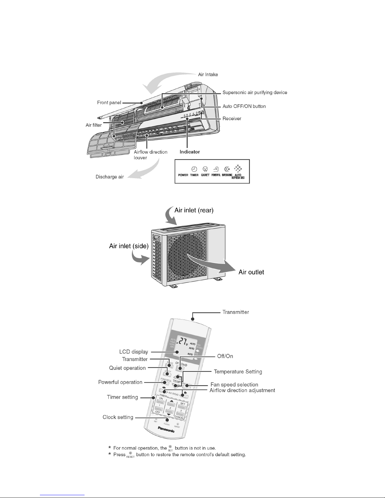
4 Location of Controls and Components
4.1. Product Overview
4.1.1. Indoor Unit
4.1.2. Outdoor Unit
4.1.3. Remote Control
11
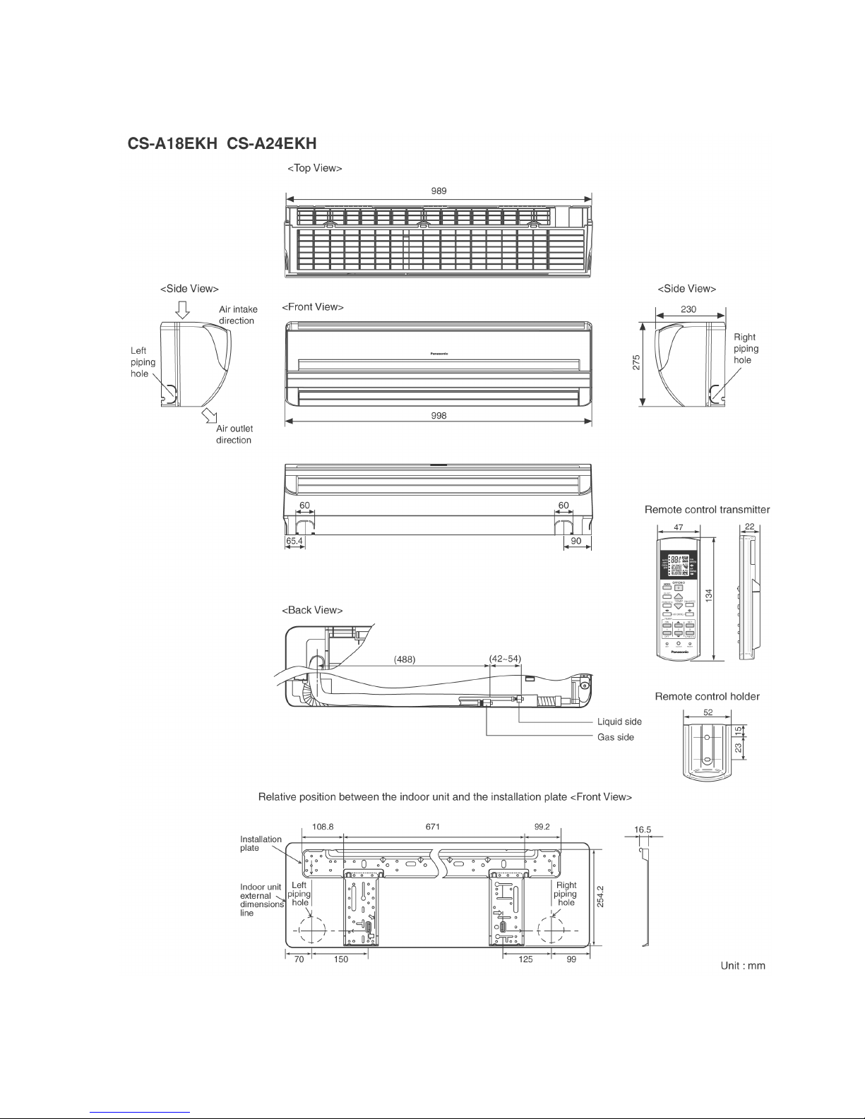
5 Dimensions
5.1. Indoor Unit
12
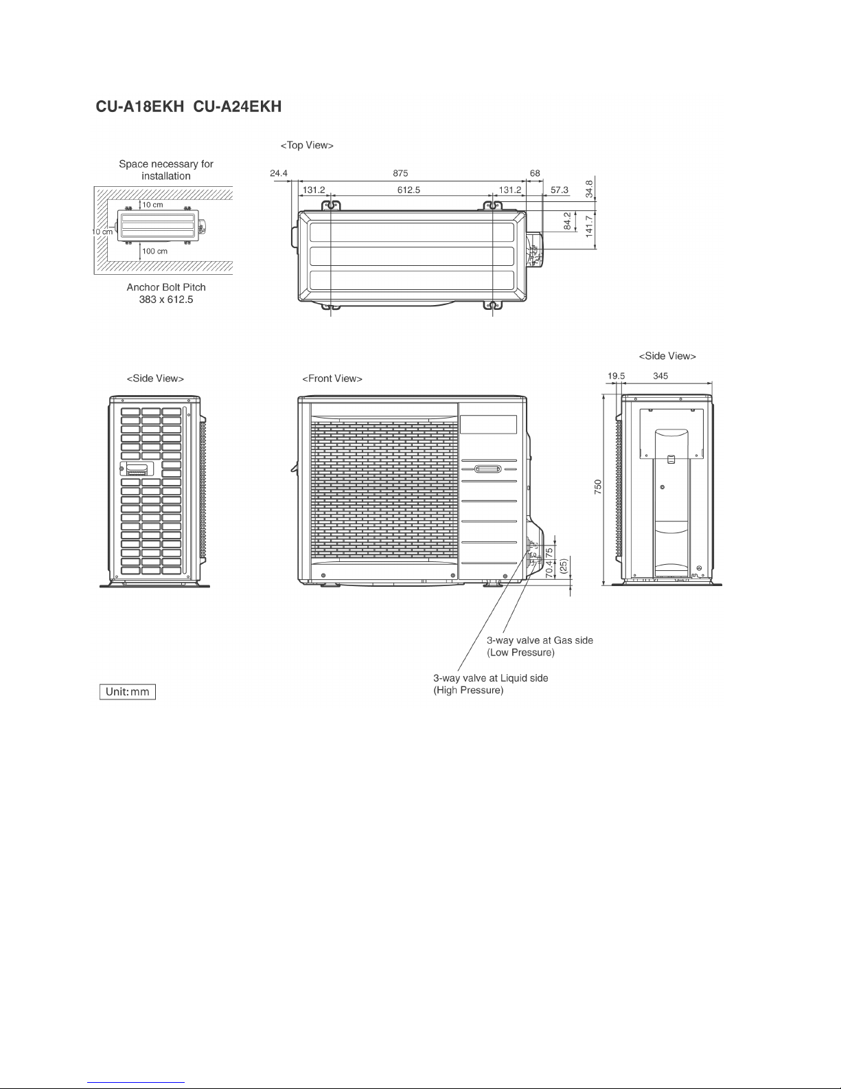
5.2. Outdoor Unit
13
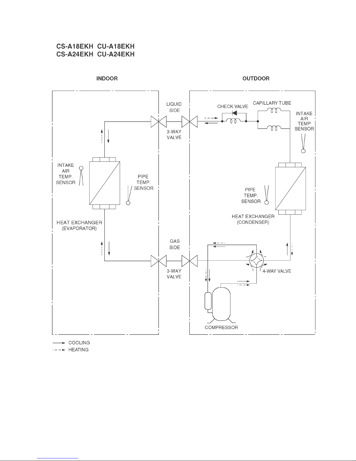
6 Refrigeration Cycle Diagram
14
7 Block Diagram
15
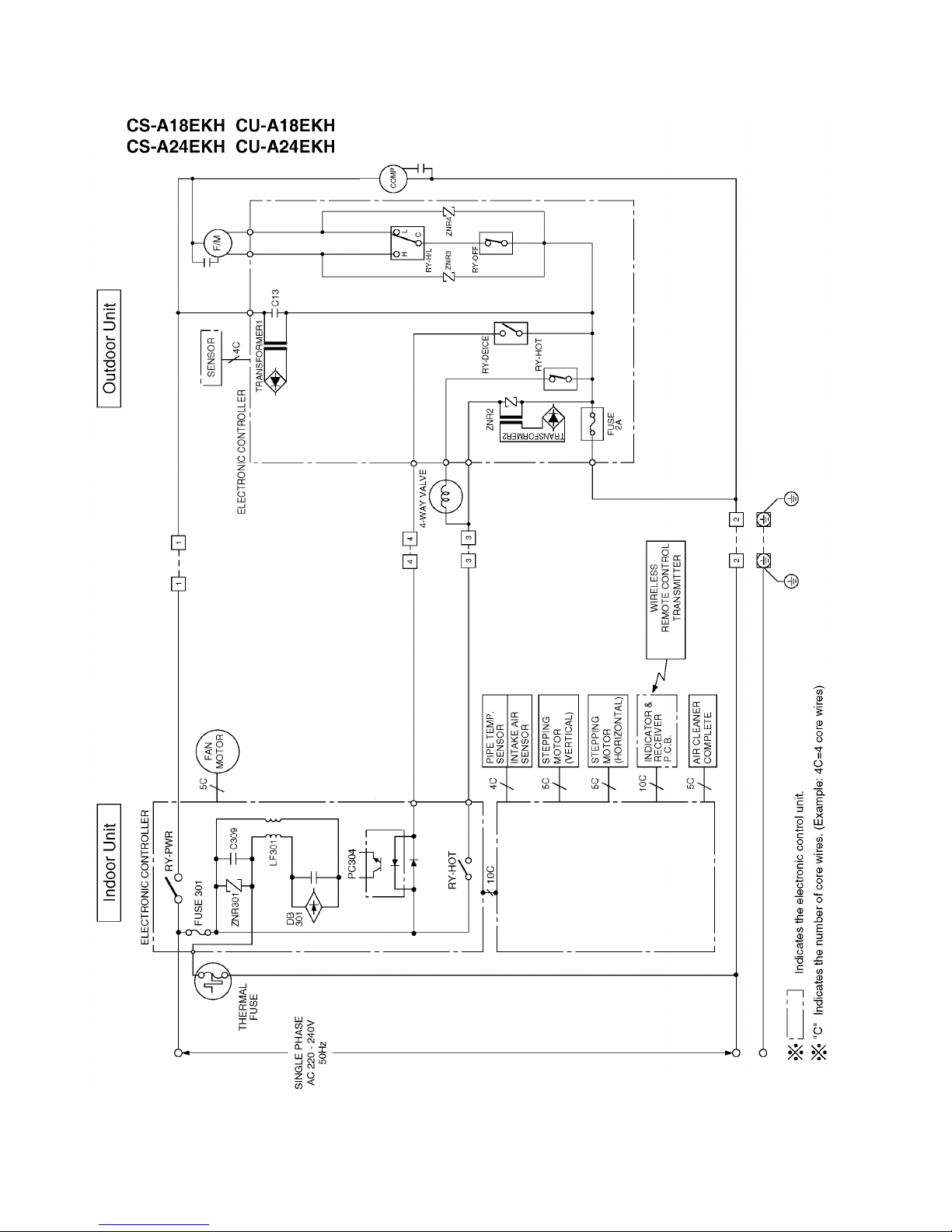
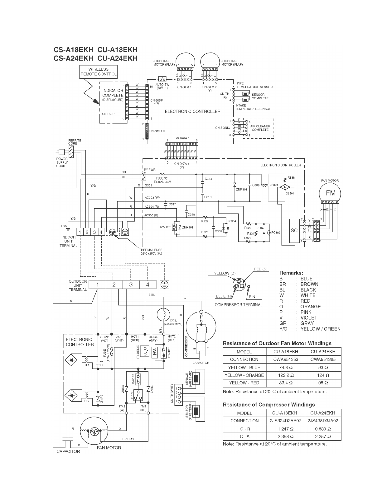
8 Wiring Connection Diagram
16
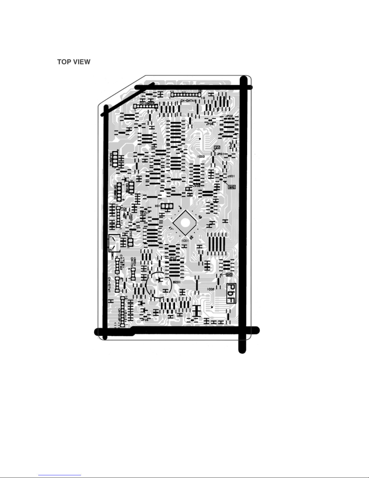
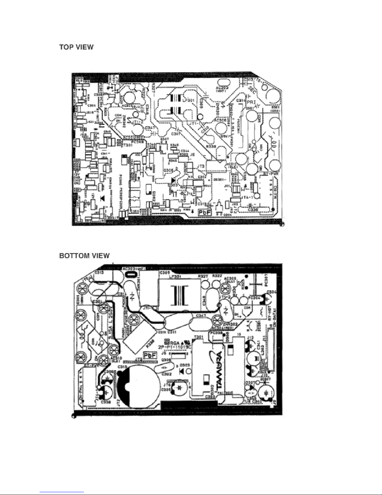
9 Printed Circuit Board
9.1. Indoor Unit (Main Printed Circuit Board)

17
18
9.2. Indoor Unit (Power Printed Circuit Board)
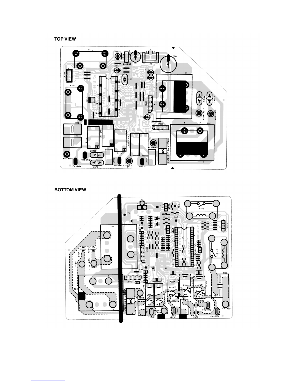
19
9.3. Outdoor Unit (Main Printed Circuit Board)
20
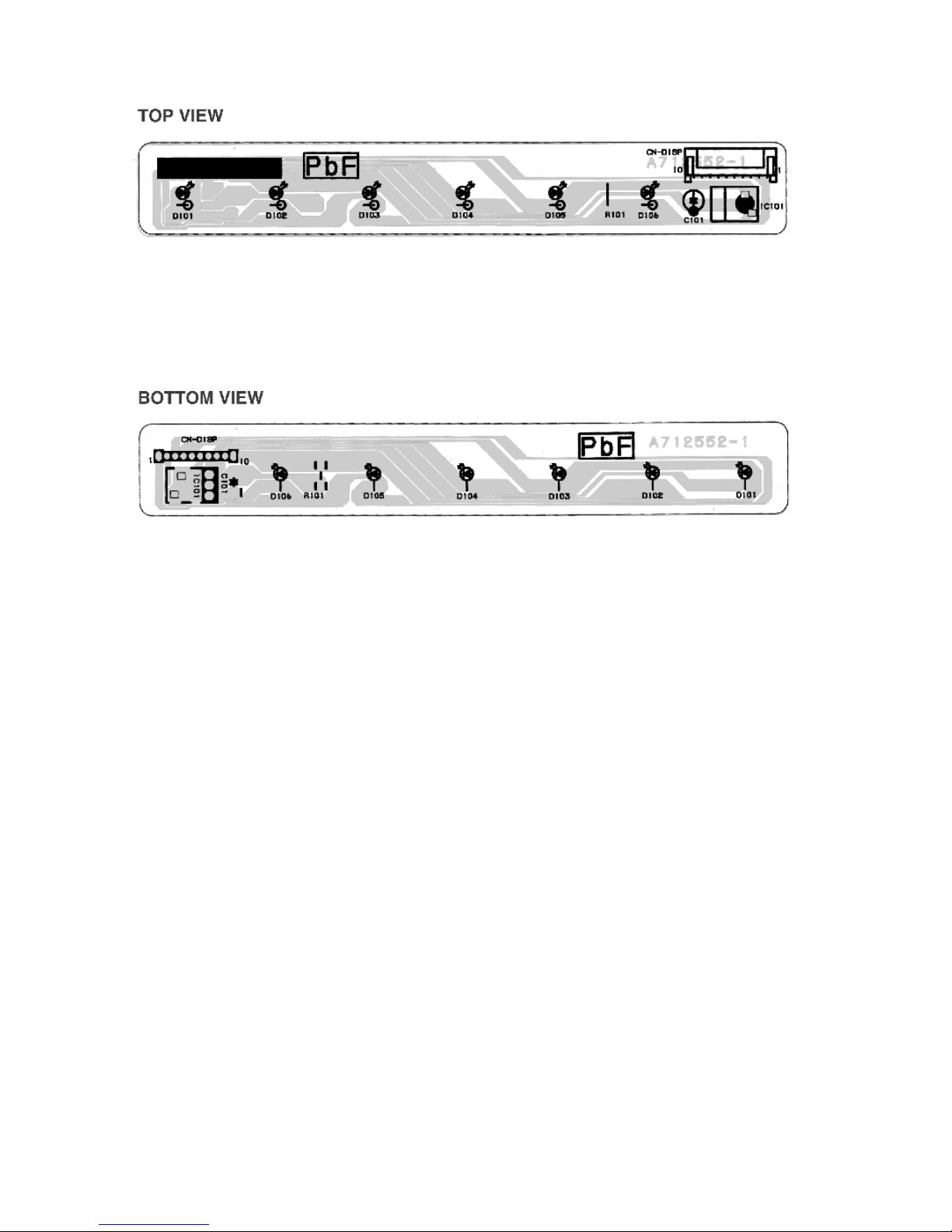
9.4. Indicator panel
 Loading...