

Page 1
Order No. MAC0501007C3
Air Conditioner
CS-A18DKD CU-A18DKD
CS-A24DKD CU-A24DKD
CONTENTS
Page Page
1 Features 2
2 Functions
2.1. Remote Control
2.2. Indoor Unit
2.3. Outdoor Unit
3 Product Specifications
3.1. CS-A18DKD CU-A18DKD
3.2. CS-A24DKD CU-A24DKD
4 Dimensions
4.1. Indoor Unit & Remote Control
4.2. Outdoor Unit
5 Refrigeration Cycle Diagram
6 Block Diagram
7 Wiring Diagram
8 Operation Details
10
10
11
12
13
14
15
3
3
4
5
6
6
8
8.1. Heating Operation 15
8.2. Cooling Operation
8.3. Soft Dry Operation
8.4. Automatic Operation
8.5. Operation Control
8.6. Indoor Fan Speed Control
8.7. Outdoor Fan Speed Control
8.8. Vertical Airflow Direction Control
8.9. Horizontal Airflow Direction Control
8.10. Powerful Operation
8.11. Quiet Operation
8.12. Ionizer Operation
8.13. Timer Control
8.14. Random Auto Restart Control
8.15. Remote Control Signal Receiving Sound
© 2004 Panasonic HA Air-Conditioning (M) Sdn Bhd
(11969-T). All rights reserved. Unauthorized copying
and distribution is a violation of law.
16
17
18
19
26
28
28
29
30
30
32
33
34
34
Page 2
CS-A18DKD CU-A18DKD / CS-A24DKD CU-A24DKD
9 Operating Instructions 35
10 Installation Instructions
10.1. Safety Precautions
10.2. Indoor Unit
10.3. Outdoor Unit
11 2-way, 3-way Valve
11.1. Evacuation of the Equipment (For Europe & Oceania
Destination)
11.2. Air Purging of the Piping and Indoor Unit
12 Servicing Information
12.1. Indoor Electronic Controllers Removal Procedures
12.2. Cross Flow Fan and Indoor Fan Motor Removal
Procedures
12.3. Remote Control Reset
12.4. Auto OFF/ON Button
13 Troubleshooting Guide
13.1. Refrigeration cycle system
41
41
44
48
51
52
58
64
64
65
66
67
68
68
1 Features
• High efficiency.
• Compact design.
• Wider range of horizontal discharge air.
• Air Filter with function to reduce dust and smoke.
• Automatic air swing and manual adjusted by Remote
Control for horizontal and vertical airflow.
• Long installation piping up to 25 meter.
• Supersonic Air Purifying System with SUPER alleru-buster.
− Inactive various harmful airbone elements including
allergens, viruses and bacteria.
− Generated supersonic waves enhance the ability to
collect dust and dirt in the air.
14 Technical Data 70
14.1. Thermostat characteristics
14.2. Operation characteristics
15 Exploded View (Indoor Unit)
15.1. CS-A18DKD CS-A24DKD
16 Replacement Parts List (Indoor Unit)
16.1. CS-A18DKD CS-A24DKD
17 Exploded View (Outdoor Unit)
17.1. CU-A18DKD CU-A24DKD
18 Replacement Parts List (Outdoor Unit)
18.1. CU-A18DKD CU-A24DKD
19 Electronic Circuit Diagram
19.1. Indoor Unit & Outdoor Unit
19.2. Remote Control
19.3. Print Pattern Indoor Unit Printed Circuit Board
19.4. Print Pattern Indicator & Receiver Printed Circuit Board
19.5. Print PatternOutdoor Unit Printed Circuit Board
70
71
73
73
74
74
75
75
76
76
77
77
83
84
85
86
• Serviceability Improvement
− Removable and washable Front Panel.
• Quality Improvement
− Random auto restart after power failure for safety restart
operation.
− Gas leakage detection.
− Prevent Compressor reverse cycle.
− Inner protector to protect Compressor.
− Noise prevention during soft dry operation.
− Blue coated Condenser for high resistance to corrosion.
− Anti-dew formation control (Cooling & Soft Dry).
− Overload Protection Control (Heating).
− Outdoor Fan Control.
− Compressor High Pressure Control.
• Operation Improvement
− Quiet mode to provide quiet operation.
− Powerful mode to reach the desired room temperature
quickly.
− Ionizer control for generating negative ion in discharge
air.
− 24-hour timer setting.
2
Page 3
2 Functions
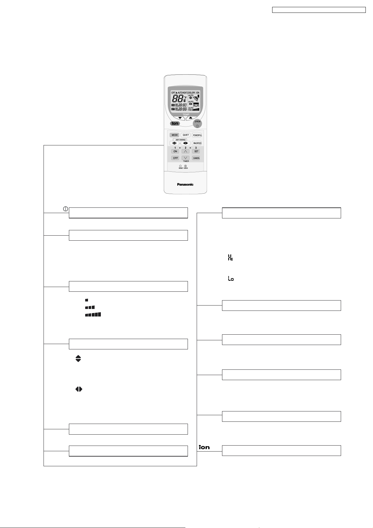
2.1. Remote Control
CS-A18DKD CU-A18DKD / CS-A24DKD CU-A24DKD
OFF / ON
MODE
FAN SPEED
AIR SWING
POWERFUL
Operation Start/Stop
Operation Mode Selection
•
•
•
•
AUTO
HEAT
COOL
DRY
Automatic Operation
Heating Operation Mode
Cooling Operation
Soft Dry Operation
Indoor Fan Speed Selection
• FAN Low Fan Speed
•
FAN Medium Fan Speed
•
FAN High Fan Speed
•
AUTO Automatic Fan Speed
FAN
Airflow Direction Control
• Vertical Automatic Airflow
Direction Control and Manual
Airflow Direction Control
(5 stages of adjustment).
•
Horizontal Automatic Airflow
Direction Control and Manual
Airflow Direction Control
(5 stages of adjustment).
Powerful Operation Start/Stop
TEMP.
ON-TIMER
OFF-TIMER
<
<
SET
CANCEL
CLOCK
Room Temperature Setting
Cooling, Soft Dry Operation.
• Increase or decrease set temperature
(16°C to 30°C)
Automatic Operation
Operation with 2°C higher than
•
standard temperature.
• Operation with standard temperature.
Operation with 2°C lower than
•
standard temperature.
Timer Operation Selection
• 24-hour, OFF / ON Real Timer Setting.
Time / Timer Setting
• Hours and minutes setting.
Timer Operation Set / Cancel
• ON Timer and OFF Timer setting and
cancellation.
Clock Setting
• Current time setting.
QUIET
Quiet Operation Start/Stop
Ionizer Operation Start/Stop
3
Page 4
CS-A18DKD CU-A18DKD / CS-A24DKD CU-A24DKD
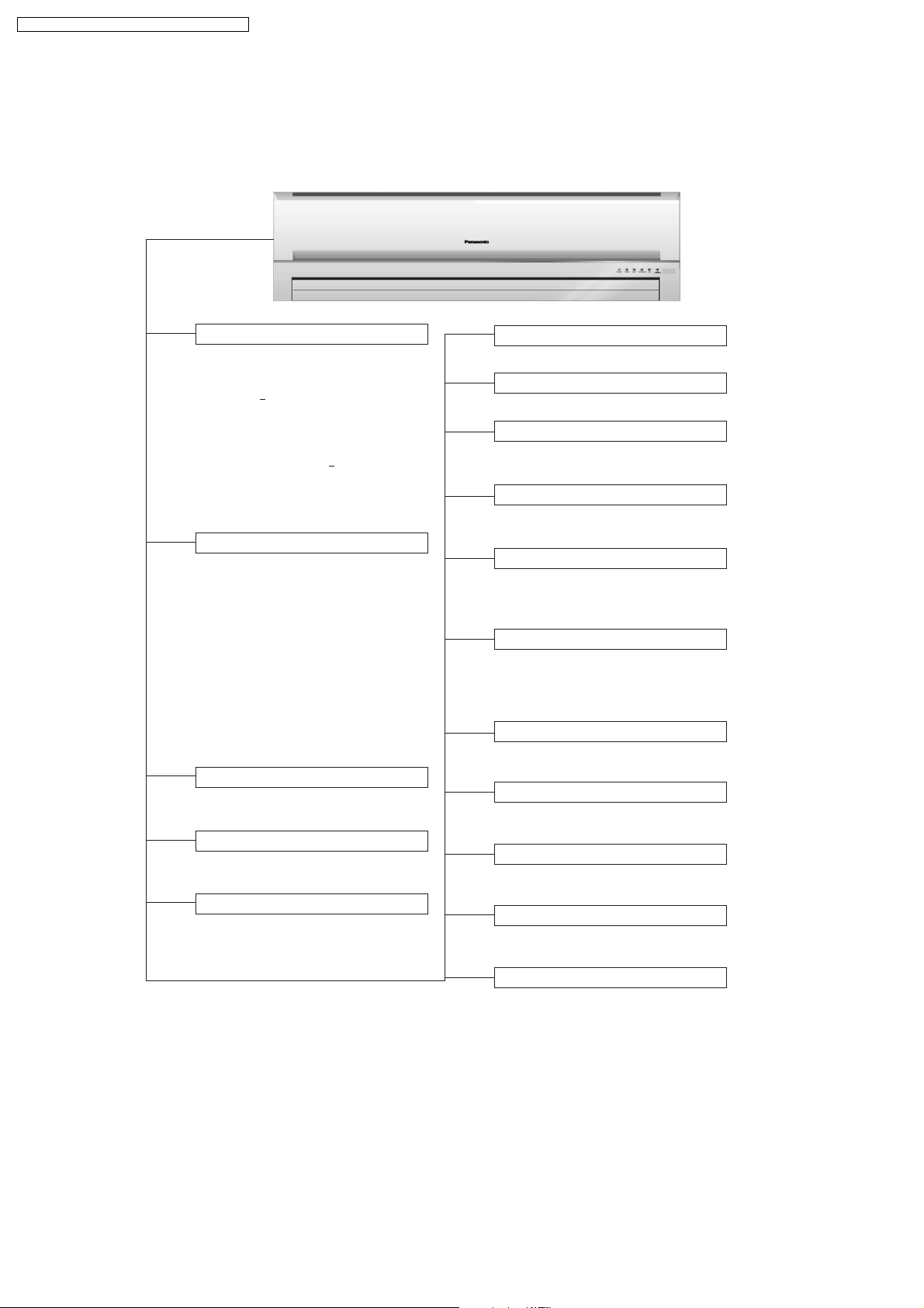
2.2. Indoor Unit
AUTO
OFF / ON
Automatic Operation Button
• Press for < 5 second to operate Automatic
operation mode.Use when the remote
control cannot be used.
• Press for > 5 second to operate Cooling
operation mode and compressor force
to on (“beep” sound will be heard). Used
when test running or servicing.
• Within 20 second of Cooling operation,
press continuously for > 5 second to enter
various setting mode. “beep, beep” sound
will be heard. (Used to toggle remote
control signal receiving sound or select
remote control transmission code.)
Operation Indication Lamps (LED)
• POWER (Green) ........ Lights up in operation,
TIMER (Orange) ....... Lights up in Timer
•
•
QUIET (Orange) ........ Lights up in Quiet
POWERFUL (Orange) .. Lights up in Powerful
•
ION (Green) ........... Lights up in Ionizer
•
SUPER
•
ALLERU-BUSTER
Operation Mode
•
Heating, Cooling, Soft Dry and Automatic
Operation.
Powerful Operation
• Reaches the desired room temperature
quickly.
Timer Operation
•
Delay OFF/ON Timer control.
(Blue)
blinks in Automatic
Operation judging.
Setting.
Operation.
Operation.
Operation.
...
Lights up in operation.
Quiet Operation
• To provide quiet operation.
Ionizer Operation
• Generate and discharge negative ion.
Random Auto Restart Control
• Unit will be restarted, when resume from
power failure, at previous setting.
Anti-Freezing Control
• To prevent indoor heat exchanger from
freezing.
Indoor Fan Speed Control
• Manual control fan speed
(High, Medium and Low).
• Automatic fan speed
Airflow Direction Control
••Vertical airflow control can be adjusted
automatically or manually by remote control.
Horizontal airflow control can be adjusted
automatically or manually by remote control.
Time Delay Safety Control
•
Restarting is inhibited for approximately
3 minutes.
7 Minutes Time Save Control
• To reduce the built up humidity inside
the room.
Anti-Dew Formation Control
• Anti-Dew Formation Control for indoor
unit discharge area.
Hot-Start Control
• To prevent cold air being discharge during
Heating operation starts.
Anti Cold Draft Control
• To prevent the cold draft during Heating
mode operation in thermo off condition.
4
Page 5
2.3. Outdoor Unit
CS-A18DKD CU-A18DKD / CS-A24DKD CU-A24DKD
Compressor Reverse Rotation
Protection Control
• To protect compressor from reverse
rotation when there is an instantaneous
power failure.
Overload Protector
• Inner protector.
60 Secs. Forced Operation Control
• Once the compressor is activated, it
does not stop within the first 60 secs.
However, it stops immediately with
remote control stop signal.
Outdoor Fan Operation Control
• 6-pole induction motor (2 speed).
For Cooling or Soft Dry operation
•
Hi-speed ............. When outdoor
temperature reaches to 31°C.
Lo-speed ............. When outdoor
temperature reaches to 29°C.
For Heating operation
•
Hi-speed ............. When outdoor
temperature reaches to 13.5°C.
Lo-speed ............. When outdoor
temperature reaches to 15.5°C.
For Over-heating Protection, the Fan is
•
switched ON or OFF depending on the
piping temperature and the outdoor
temperature.
Deice Control
• To prevent frosting at outdoor heat
exchanger during Heating Operation.
4-Way Valve Control
• When the unit is switched to “OFF”
during Heating Operation, 4-way valve
stays at Heating position for 5 minutes.
5
Page 6
CS-A18DKD CU-A18DKD / CS-A24DKD CU-A24DKD
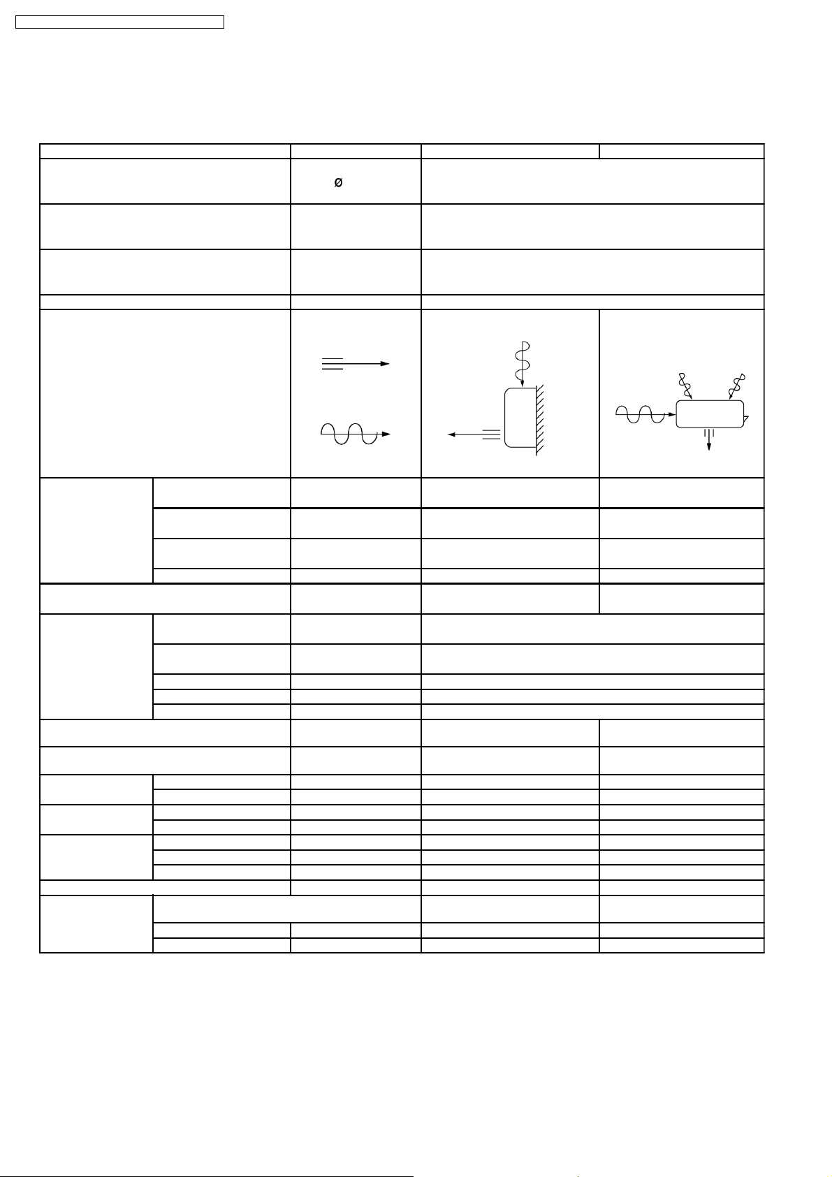
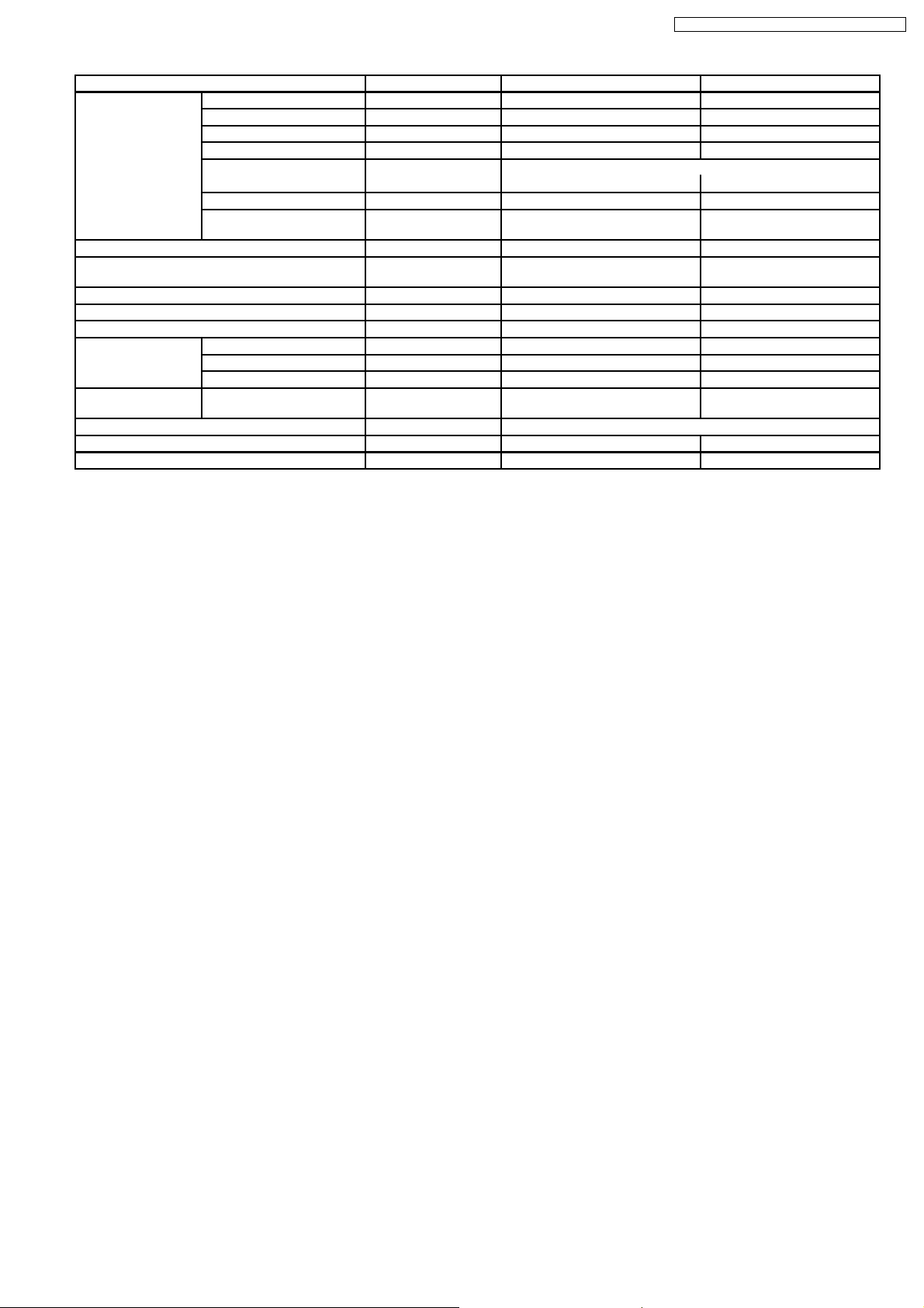
3 Product Specifications
3.1. CS-A18DKD CU-A18DKD
Unit CS-A18DKD CU-A18DKD
Power Source (Phase, Voltage, Cycle) ,V,Hz Single, 220 - 230, 50
Cooling Capacity kW (BTU/h) 5.30 (18,10 0) - 5.30 (18,100)
Heating Capacity kW (BTU/h) 5.65 (19,300) - 5.70 (19,400)
Moisture Removal l/h (Pint/h) 2.9 (6.1)
Airflow Method OUTLET
INTAKE
Air Volume Lo m3/min (cfm) Cooling; 13.1 (460) - 13.1 (460) 28.6 (1,010) - 31.1 (1,100)
Heating; 14.2 (500) - 14.2 (500)
Me m3/min (cfm) Cooling; 14.5 (510) - 14.5 (510) —
Heating; 14.7 (520) - 14.7 (520)
Hi m3/min (cfm) Cooling; 15.3 (540) - 15.3 (540) 50.7 (1,790) - 52.7 (1,860)
Heating; 16.0 (560) - 16.0 (560)
SHi m3/min (cfm) Cooling; 16.0 (560) - 16.0 (560) —
Noise Level dB (A) Cooling; High 43 - 43, Low 38 -38 Cooling; High 53 - 54
Heating; High 42 - 42, Low 38 -38 Heating; High 54 - 55
Electrical Data Input Power kW Cooling; 1.72 - 1.76
Running Current A Cooling; 8.0 - 7.8
EER W/W (BTU/hW) Cooling; 3.08 - 3.01 (10.52 - 10.28)
COP W/W (BTU/hW) Heating; 3.42 - 3.33 (11.70 - 11.35)
Starting Current A 44.5
Piping Conne ction Port
(Flare piping)
Pipe Size
(Flare piping)
Drain
Hose
Power Cord Length m 1.9 —
Dimensions Height inch (mm) 10 - 13/16 (275) 29 - 17/32 (750)
Net Weight lb (kg) 24 (11.0) 132 (60.0)
Compressor Description — Rotary (1 cylinder)
Inner diame ter mm 12 —
Length mm 650 —
Number of core-wire 3 (1.5 mm2) —
Width inch (mm) 39 - 9/32 (998) 34 - 7/16 (875)
Depth inch (mm) 9 - 1/16 (230) 13 - 19/32 (345)
Motor Type — Induction (2-poles)
Rated Output kW — 1.5
inch
inch
inch
inch
SIDE VIEW TOP VIEW
Heating; 1.65 - 1.71
Heating; 7.7 - 7.6
G ; Half Union 1/2”
L ; Half Union 1/4”
G ; (gas side) 1/2”
L ; (liquid side) 1/4”
G ; 3-way valve 1/2”
L ; 3-way valve 1/4”
G ; (gas side) 1/2”
L ; (liquid side) 1/4”
rolling piston type
6
Page 7
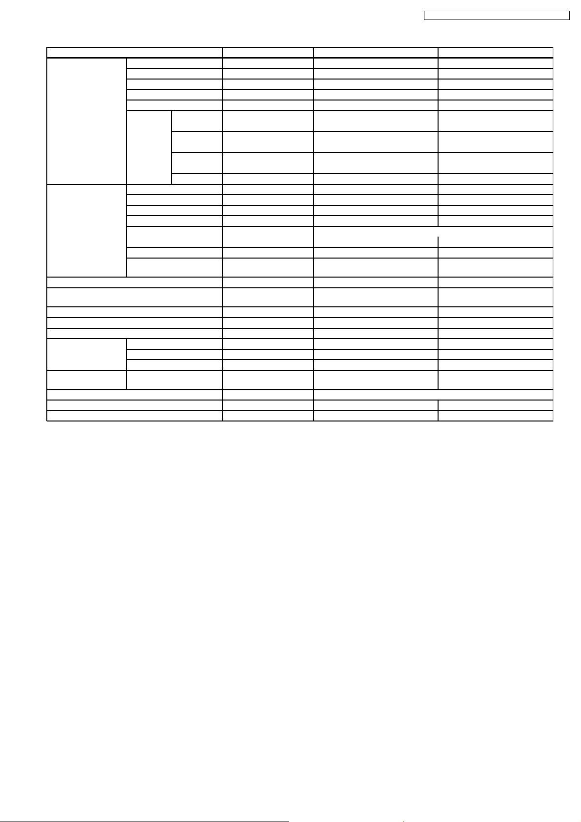
CS-A18DKD CU-A18DKD / CS-A24DKD CU-A24DKD
Unit CS-A18DKD CU-A18DKD
Air Circulation Description Cross-flow Fan Propeller Fan
Material ASHT-18 PP
Motor Type Transistor (8-poles) Induction (6-poles)
Input W 50.0 - 50.0 150.3 - 150.3
Rated Output W 30 80
Fan Speed Low rpm Cooling; 1,160 - 1,160 460 - 490
Heating; 1,240 - 1,240
Medium rpm Cooling; 1,290 - 1,290 —
Heating; 1,290 - 1,290
High rpm Cooling; 1,360 - 1,360 815 - 830
Heating; 1,400 - 1,400
SuperHigh rpm Cooling; 1,400 - 1,400 —
Heat Exchanger Description Evaporator Condenser
Tube material Copper Copper
Fin material Aluminium (Pre Coat) Aluminium
Fin Type Slit Fin Corrugated Fin
Row / Stage (Plate fin configuration, forced draft)
2×15 2×28
FPI 21 16
Size (W × H × L) mm 810 × 315 × 25.4 827.7
Refrigerant Control Device — Capillary Tube
Refrigeration Oil (cm3) — SUNISO 4GDID or ATMOS
Refrigerant (R-22) g (oz) — 1,710 (60.4)
Thermostat — —
Protection Device — Inner Protector
Capillary Tube Length mm — Cooling; 970, Heating; 820
Flow Rate l/min — Cooling; 11.0, Heating; 27.0
Inner Diameter mm — Cooling; 1.6, Heating; 2.2
Air Filter Material
Style
Capacity Control Capillary Tube
Compressor Capacitor µF, VAC — 45 µF, 400/440VAC
Fan Motor Capacitor µF, VAC — 3.5 µF, 440VAC
P.P.
Honeycomb
× 711.2 × 44
862.2
M60 or ATMOS 56M
—
Note:
• Specifications are subject to change without notice for further improvement.
7
Page 8
CS-A18DKD CU-A18DKD / CS-A24DKD CU-A24DKD
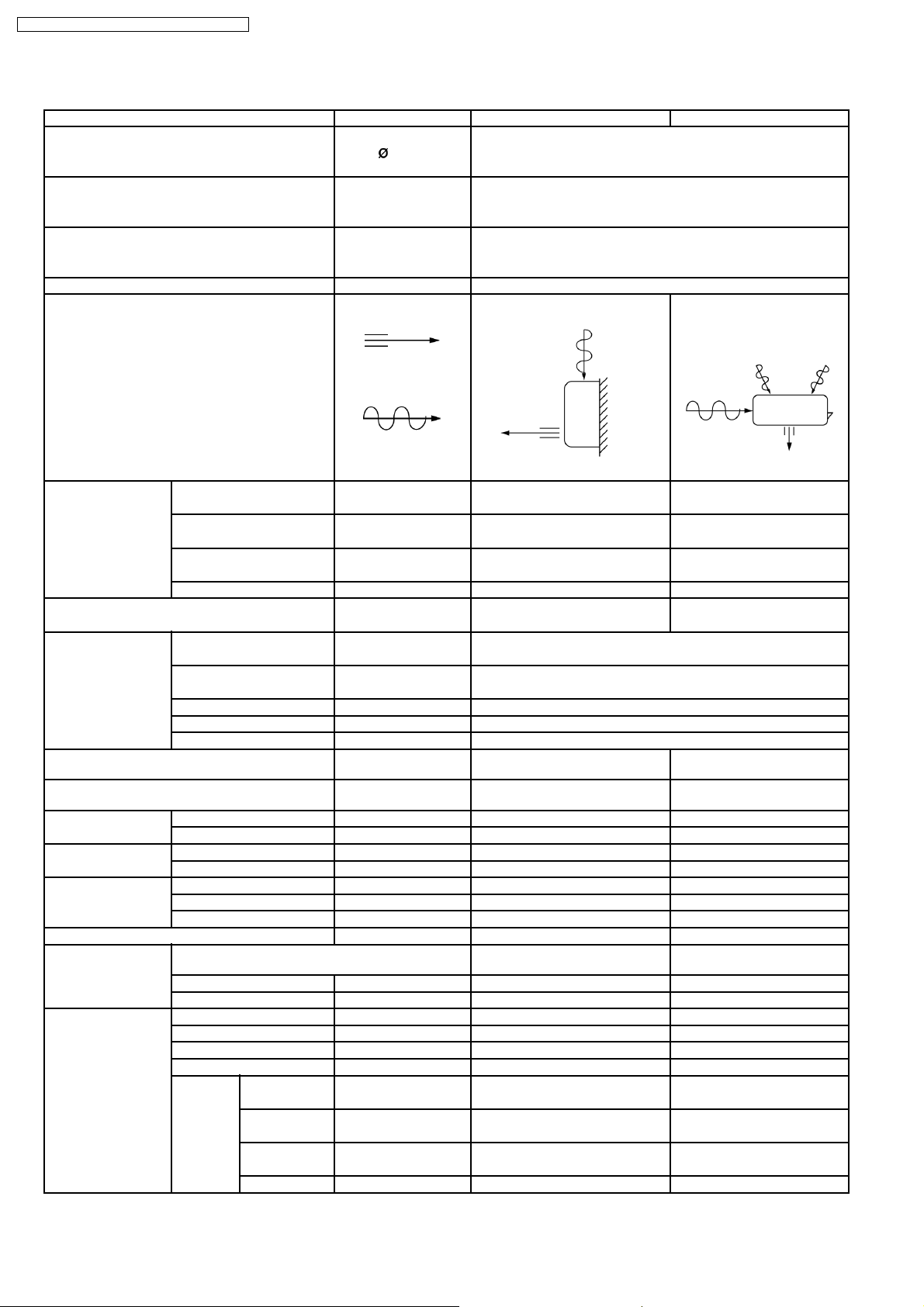
3.2. CS-A24DKD CU-A24DKD
Unit CS-A24DKD CU-A24DKD
Power Source (Phase, Voltage, Cycle) ,V,Hz Single, 220 - 230, 50
Cooling Capacity kW (BTU/h) 7.03 - 7.03 (24,00 0 - 24,000)
Heating Capacity kW (BTU/h) 7.80 - 7.80 (26,600 - 26,600 )
Moisture Removal l/h (Pint/h) 4.0 (8.5)
Airflow Method OUTLET
INTAKE
Air Volume Lo m3/min (cfm) Cooling; 13.7 (480) - 13.7 (480) 28.1 (990) - 29.9 (1,055)
Heating; 14.7 (520) - 14.7 (520)
Me m3/min (cfm) Cooling; 15.8 (560) - 15.8 (560) —
Heating; 15.8 (560) - 15.8 (560)
Hi m3/min (cfm) Cooling; 16.8 (590) - 16.8 (590) 49.7 (1,750) - 50.7 (1,790)
Heating; 17.6 (620) - 17.6 (620)
SHi m3/min (cfm) Cooling; 17.6 (620) - 17.6 (620) —
Noise Level dB (A) Cooling; High 47 - 47, Low 41 - 41 Cooling; High 53 - 54
Heating; High 46 - 46, Low 41 - 41 Heating; High 54 - 55
Electrical Data Input Power kW Cooling; 2.54 - 2.58
Running Current A Cooling; 12.3 - 12.2
EER W/W (BTU/hW) Cooling; 2.77 - 2.72 (9.45 - 9.30)
COP W/W (BTU/hW) Heating; 3.08 - 3.05 (10.51 - 10.39)
Starting Current A 65.0
Piping Conne ction Port
(Flare piping)
Pipe Size
(Flare piping)
Drain
Hose
Power Cord Length m 1.9 —
Dimensions Height inch (mm) 10 - 13/16 (275) 29 - 17/32 (750)
Net Weight lb (kg) 26 (12.0) 139 (63.0)
Compressor Description — Rotary (1 cylinder) rolling
Air Circulation Description Cross-flow Fan Propeller Fan
Inner diame ter mm 12 —
Length mm 650 —
Number of core-wire 3 (2.5 mm2) —
Width inch (mm) 39 - 9/32 (998) 34 - 7/16 (875)
Depth inch (mm) 9-1/16 (230) 13 - 19/32 (345)
Motor Type — Induction (2-poles)
Rated Output kW — 2.0
Material ASHT-18 PP
Motor Type Transistor (8-poles) Induction (6-poles)
Rated Output W 30 80
Fan Speed Low rpm Cooling; 1,280 - 1,280 460 - 490
Medium rpm Cooling; 1,480 - 1,480 —
High rpm Cooling; 1,570 - 1,570 815 - 830
SuperHigh rpm Cooling; 1,650 - 1,650 —
inch
inch
inch
inch
SIDE VIEW TOP VIEW
Heating; 2.53 - 2.56
Heating; 12.2 - 12.1
G ; Half Union 5/8”
L ; Half Union 1/4”
G ; (gas side) 5/8”
L ; (liquid side) 1/4”
Heating; 1,380 - 1,380
Heating; 1,480 - 1,480
Heating; 1,650 - 1,650
G ; 3-way valve 5/8”
L ; 3-way valve 1/4”
G ; (gas side) 5/8”
L ; (liquid side) 1/4”
piston type
8
Page 9
CS-A18DKD CU-A18DKD / CS-A24DKD CU-A24DKD
Unit CS-A24DKD CU-A24DKD
Heat Exchanger Description Evaporator Condenser
Tube material Copper Copper
Fin material Aluminium (Pre Coat) Aluminium
Fin Type Slit Fin Corrugated Fin
Row / Stage (Plate fin configuration, forced draft)
2×15 2×28
FPI 21 18
Size (W × H × L) mm 810 × 315 × 25.4 827.7
Refrigerant Control Device — Capillary Tube
Refrigeration Oil (cm3) — SUNISO 4GDID or ATMOS
Refrigerant (R-22) g (oz) — 2,050 (72.4)
Thermostat — —
Protection Device — Inner Protector
Capillary Tube Length mm — Cooling; 730, Heating; 340
Flow Rate l/min — Cooling; 12.5, Heating; 21.0
Inner Diameter mm — Cooling; 1.6, Heating; 2.0
Air Filter Material
Style
Capacity Control Capillary Tube
Compressor Capacitor µF, VAC — 45 µF, 400/440VAC
Fan Motor Capacitor µF, VAC — 3.5 µF, 440VAC
P.P.
Honeycomb
× 711.2 × 44.0
862.2
M60 or ATMOS 56M
—
Note:
• Specifications are subject to change without notice for further improvement.
9
Page 10
CS-A18DKD CU-A18DKD / CS-A24DKD CU-A24DKD
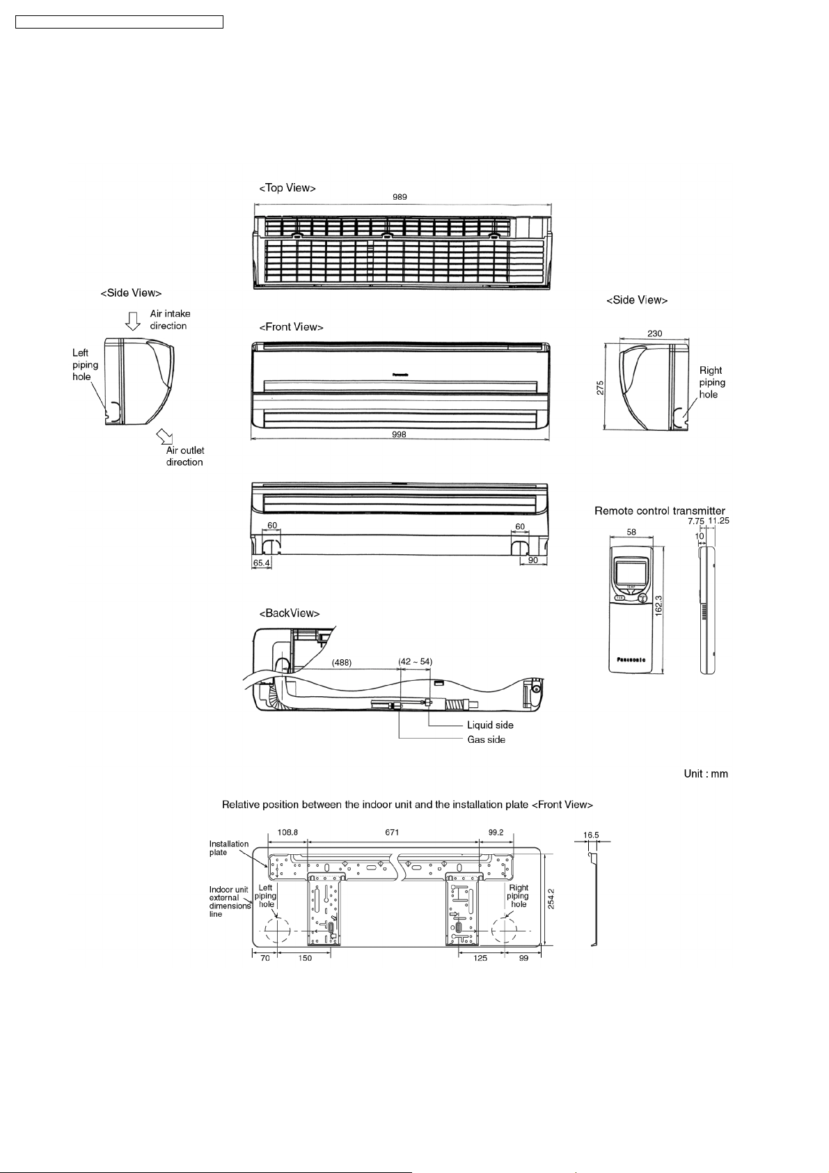
4 Dimensions
4.1. Indoor Unit & Remote Control
4.1.1. CS-A18DKD CS-A24DKD
10
Page 11
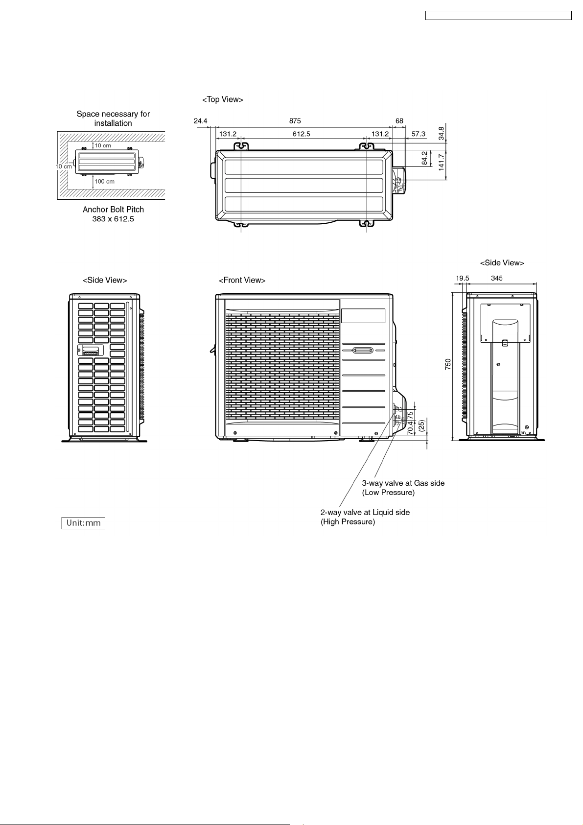
4.2. Outdoor Unit
4.2.1. CU-A18DKD CU-A24DKD
CS-A18DKD CU-A18DKD / CS-A24DKD CU-A24DKD
11
Page 12
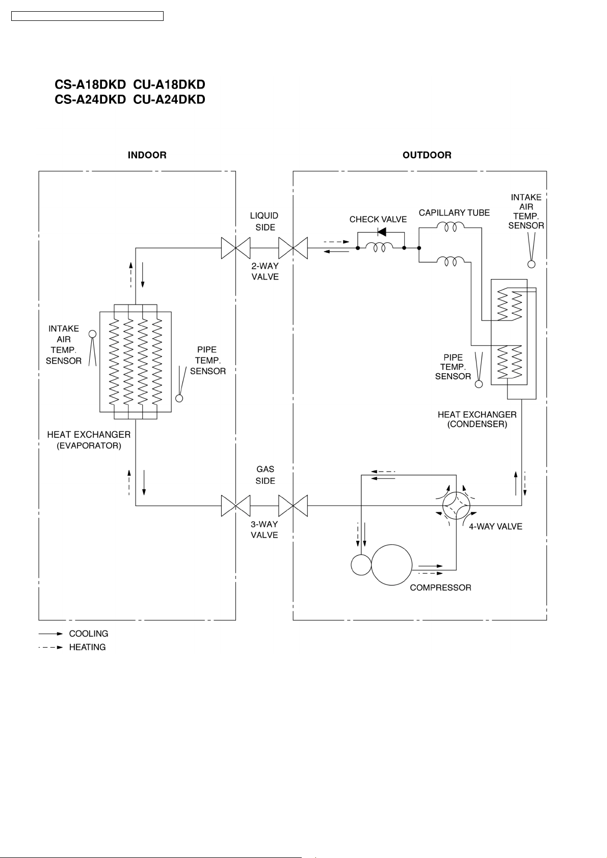
CS-A18DKD CU-A18DKD / CS-A24DKD CU-A24DKD
5 Refrigeration Cycle Diagram
12
Page 13
6 Block Diagram
CS-A18DKD CU-A18DKD / CS-A24DKD CU-A24DKD
13
Page 14
CS-A18DKD CU-A18DKD / CS-A24DKD CU-A24DKD
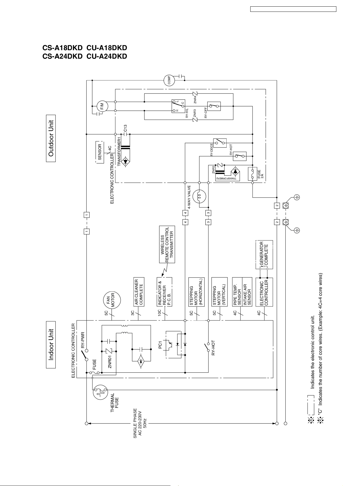
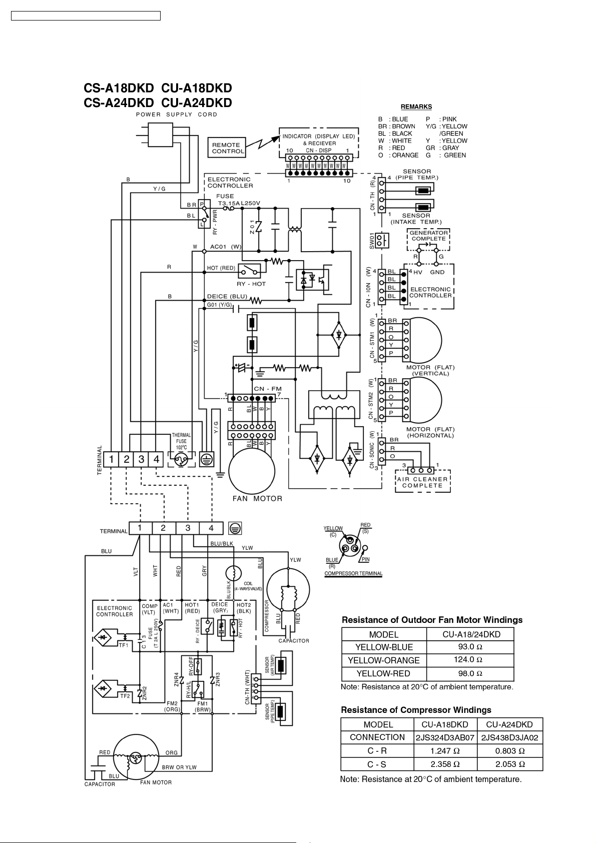
7 Wiring Diagram
14
Page 15
CS-A18DKD CU-A18DKD / CS-A24DKD CU-A24DKD
8 Operation Details
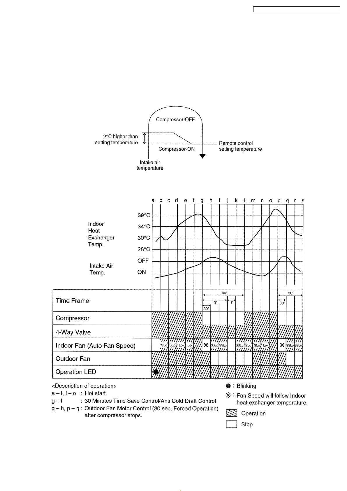
8.1. Heating Operation
• Heating operation can be set using remote control.
• This operation is applied to warm the room temperature reaches the setting temperature set on the remote control.
• The remote control setting temperature, which takes the reading of intake air temperature sensor, can be adjusted from 16°C
to 30°C.
• During Heating operation, the compressor will stop running and restart as shown in below figure.
8.1.1. Heating Operation Time Diagram
15
Page 16
CS-A18DKD CU-A18DKD / CS-A24DKD CU-A24DKD
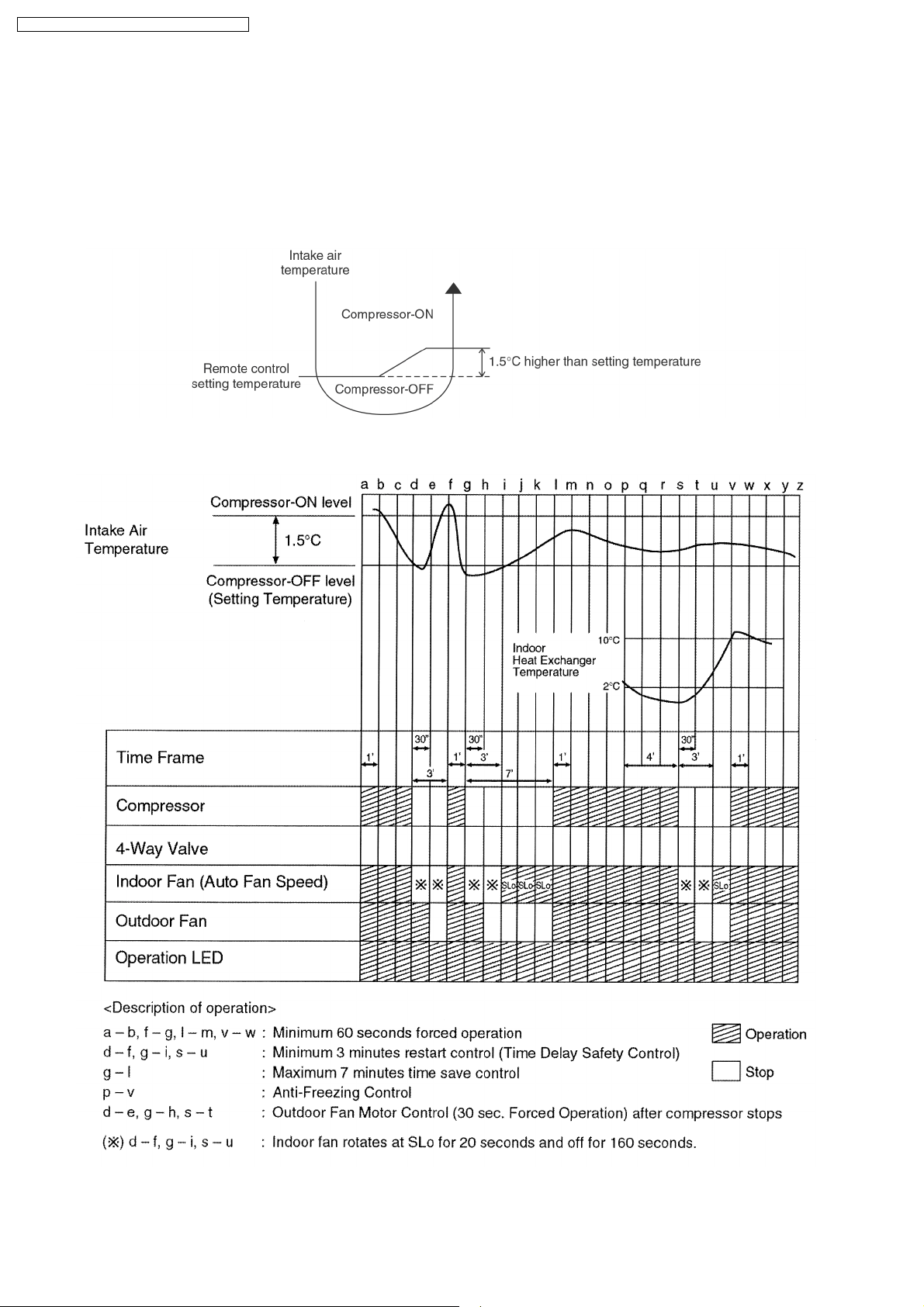
8.2. Cooling Operation
• Cooling operation can be set using remote control.
• This operation is applied to cool down the room temperature reaches the setting temperature set on the remote control.
• The remote control setting temperature, which takes the reading of intake air temperature sensor, can be adjusted from 16°C
to 30°C.
• During cooling operation, the compressor will stop running and restart as shown in below figure.
8.2.1. Cooling Operation Time Diagram
16
Page 17
CS-A18DKD CU-A18DKD / CS-A24DKD CU-A24DKD
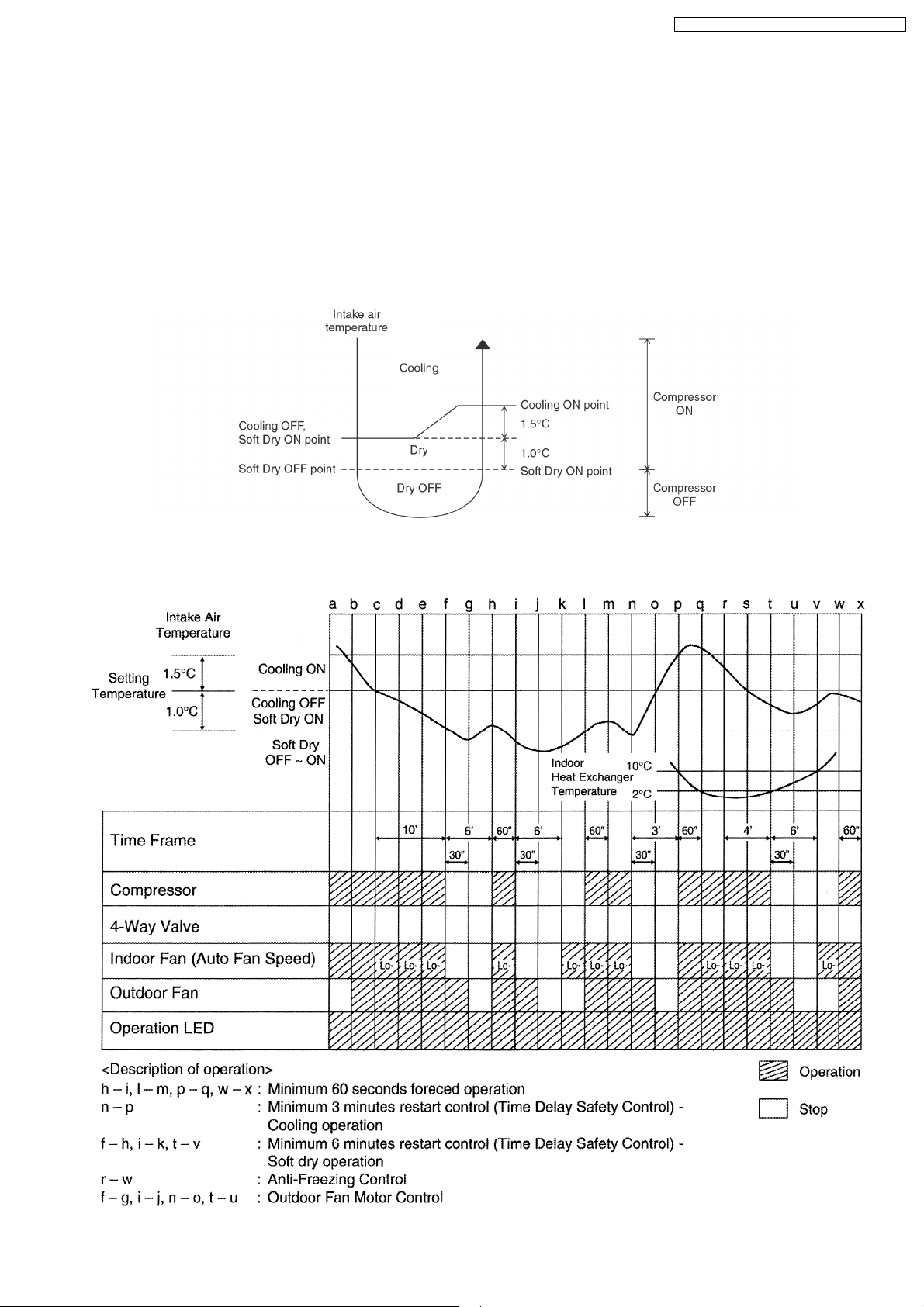
8.3. Soft Dry Operation
• Soft Dry operation can be set using remote control.
• Soft Dry operation is applied to dehumidify and to perform a gentle cooling to the room.
• This operation starts when the intake air temperature sensor reaches the setting temperature on the remote control.
• When operation begins, Soft Dry will be switched “ON” for a maximum 10 minutes, then Soft Dry operation will be turned “OFF”
for a minimum 6 minutes. After that, the Soft Dry operation will be “ON” and “OFF” based on the setting temperature as shown
in below figure.
• However after 3 minutes of compressor off, during Soft Dry “OFF” (within 6 minutes Soft Dry restart control), the indoor unit will
start to operate at normal Cooling mode if the intake temperature is higher than Cooling “ON” point.
8.3.1. Soft Dry Operation Time Diagram
17
Page 18
CS-A18DKD CU-A18DKD / CS-A24DKD CU-A24DKD
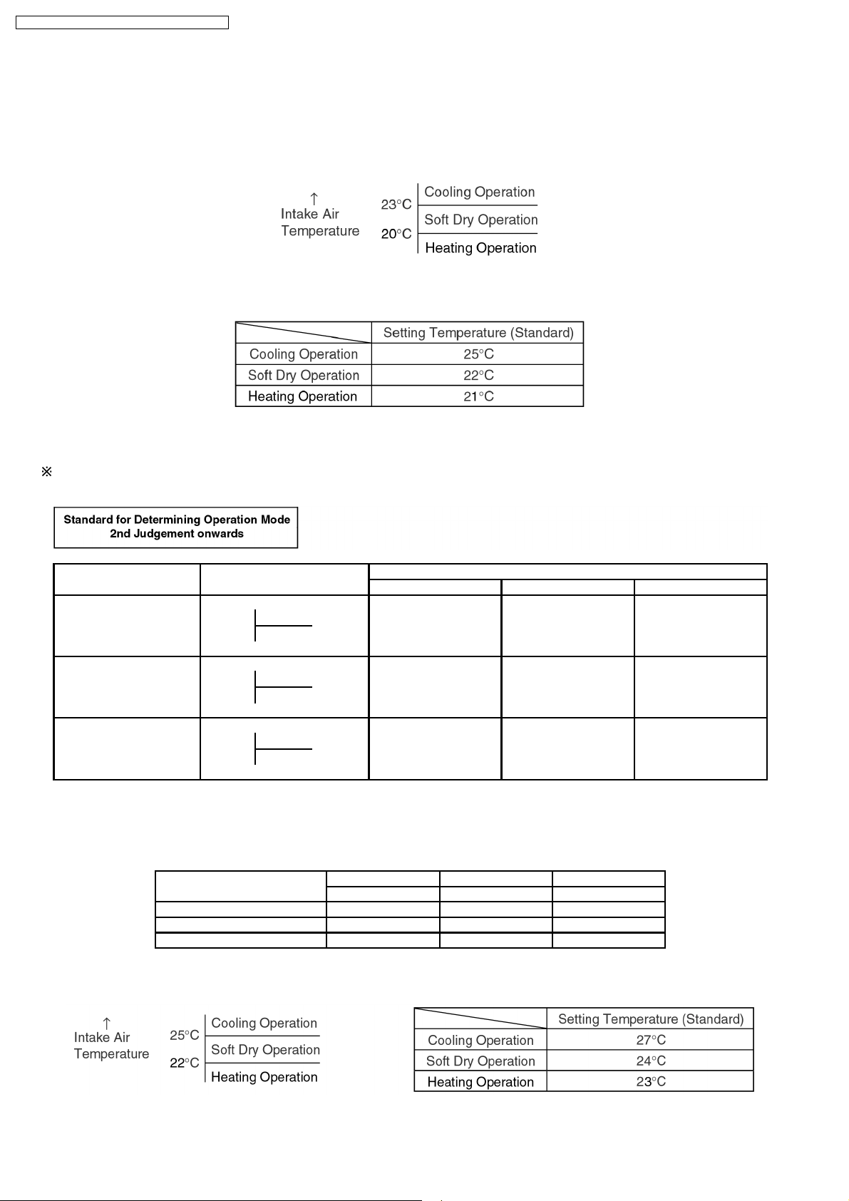
8.4. Automatic Operation
• Automatic operation can be set using remote control.
• This operation starts to operate with indoor fan at SLo speed for 25 seconds to judge the intake air temperature.
• After judged the temperature, the operation mode is determined by refering to the below standard.
• Then, the unit start to operate at determined operation mode, until it is switched off using remote control, with the setting
temperature as shown in below table.
• Operation mode will be determine again for judgement after 1 hour of operation, if the room temperature reaches to set
temperature and compressor off time is over 7 minutes 30 seconds continuously.
The present mode will be continued, if the room temperature does not reach to set temperature (Compressor keeps running) eventhrough after
1 hour from automatic operation mode started.
Present Judgement Next Mode
Mode Cooling Soft Dry Heating
O O
Cooling 23°C Cooling (Judgement: Not Applicable (Judgement:
Heating 23°C & Above) Below 23°C)
O O
Soft Dry 20°C Soft Dry Not Applicable (Judgement: (Judgement:
Heating 20°C & Above) Below 20°C)
O O
Heating Cooling (Judgement: Not Applicable (Judgement:
25°C Heating 25°C & Above) Below 25°C)
• Automatic Set Temperature
For each operation, set temperature will automaticlly set as shown below.
• The setting temperature for all the operations can be changed one level up or one level down from the standard temperature
as shown in below table by pressing on the temperature up or temperature down button at remote control.
Operation Hi (Standard) Lo
(+2°C) (±0°C) (-2°C)
Cooling 27°C 25°C 23°C
Soft Dry 24°C 22°C 20°C
Heating 23°C 21°C 19°C
• The operation mode judging temperature and standard setting temperature can be increased by 2°C permanently, by open the
circuit of JX1 at indoor electronic controller.
18
Page 19
CS-A18DKD CU-A18DKD / CS-A24DKD CU-A24DKD
8.5. Operation Control
8.5.1. Restart Control (Time Delay Safety Control)
• When the thermo-off temperature (temperature which compressor stops to operate) is reached during:-
− Cooling/Heating operation - the compressor stops for 3 minutes (minimum) before resume operation.
− Soft Dry operation - the compressor stops for 6 minutes (minimum) before resume operation.
• If the operation is stopped by the remote control, the compressor will not turn on within 3 minutes from the moment operation
stop, although the unit is turn on again within the period.
• This phenomenon is to balance the pressure inside the refrigerant cycle.
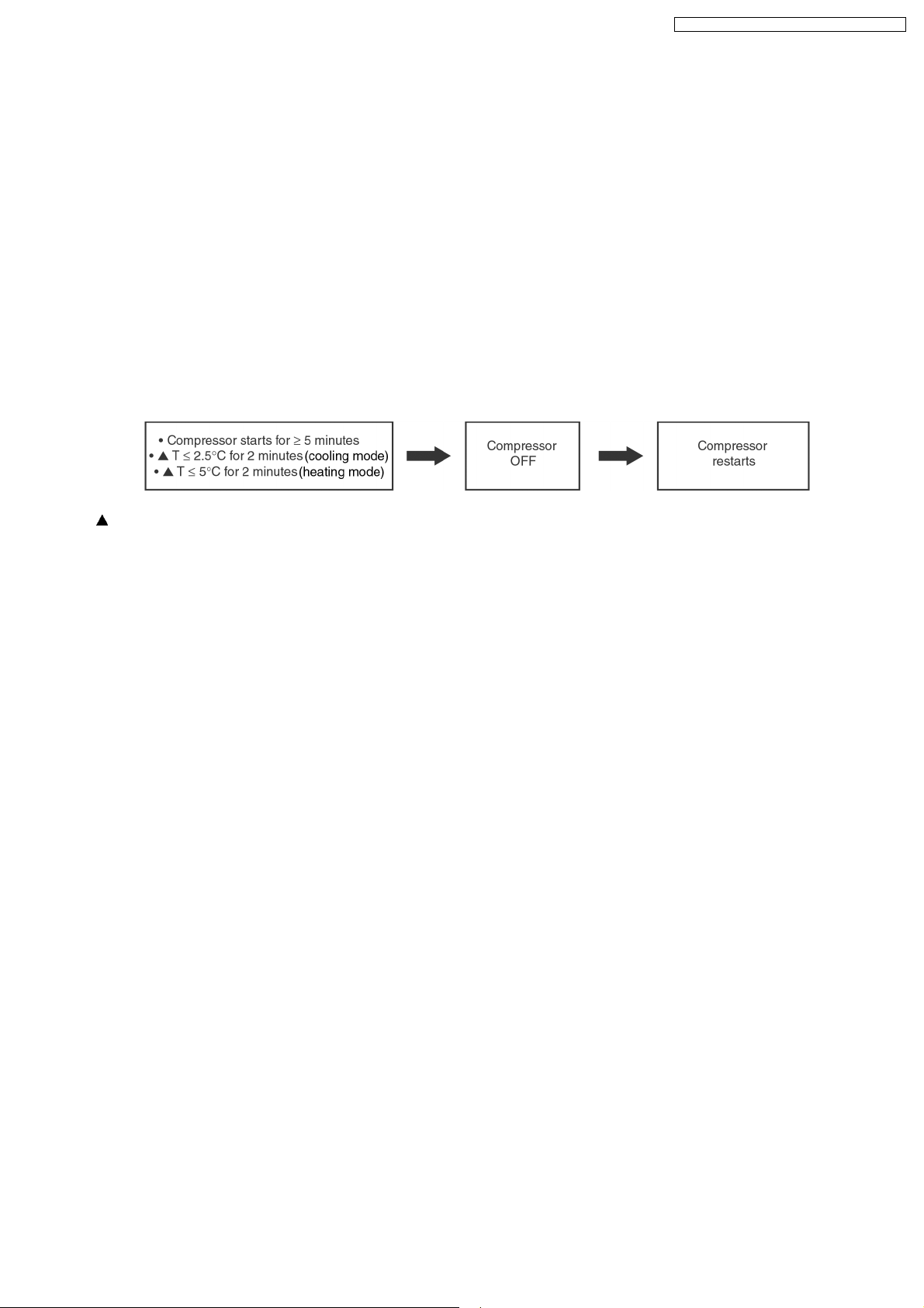
8.5.2. Compressor Reverse Rotation Protection Control
• If the compressor is operating continuously for 5 minutes or longer and the temperature difference between intake air and
indoor heat exchanger is 2.5°C (cooling mode)/5°C (heating mode) or less for continuous 2 minutes, compressor will stop and
restart automatically.
• Time Delay Safety Control is activated before the compressor restart.
T = Intake air temperature - Indoor heat exchanger temperature
• This is to prevent compressor from rotate reversely when there is an instantaneous power failure.
19
Page 20
CS-A18DKD CU-A18DKD / CS-A24DKD CU-A24DKD
(For 8.5.3. to 8.5.7. information applies only to Cooling and Soft Dry Operation)
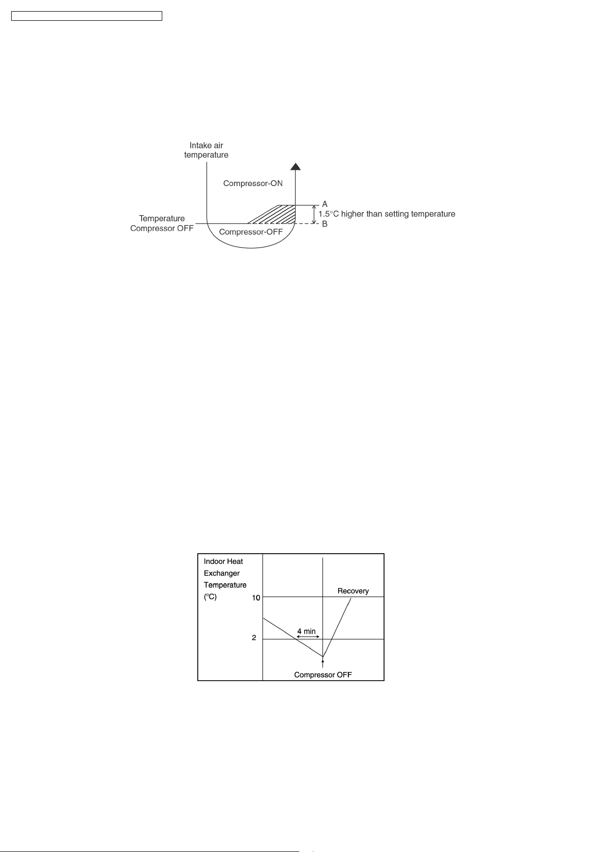
8.5.3. 7 Minutes Time Save Control
• The compressor will start automatically if it has stopped for 7 minutes and the intake air temperature falls between the
compressor ON temperature (A) and compressor OFF temperature (B) during the period.
• This phenomenon is to reduce the built up humidity inside a room.
8.5.4. 60 Seconds Forced Operation
• Once the air conditioner is turned on, the compressor will not stop within 60 seconds in a normal operation although the intake
air temperature has reached the thermo-off temperature. However, force stop by pressing the OFF/ON operation button at the
remote control is permitted.
• The reason for the compressor to force operate at minimum 60 seconds is to allow the refrigerant oil run in a full cycle and
return back to the outdoor unit.
8.5.5. Starting Current Control
• When the compressor, outdoor fan motor and indoor fan motor are simultaneously started, the indoor fan motor will start to
operate at 1.6 second later.
• The reason of the difference is to reduce the starting current flow.
8.5.6. Anti-Freezing Control
• If the temperature of the indoor heat exchanger falls below 2°C continuously for 4 minutes or more, the compressor turns off.
The fan speed setting remains the same.
• This phenomenon is to protect the indoor heat exchanger from freezing and to prevent higher volume of refrigerant in liquid form
returning to the compressor.
• Compressor will restart again when the indoor heat exchanger temperature rises to 10°C (Recovery).
• Restart control (Time Delay Safety Control) will be applied in this Control if the recovery time is too short.
20
Page 21
CS-A18DKD CU-A18DKD / CS-A24DKD CU-A24DKD
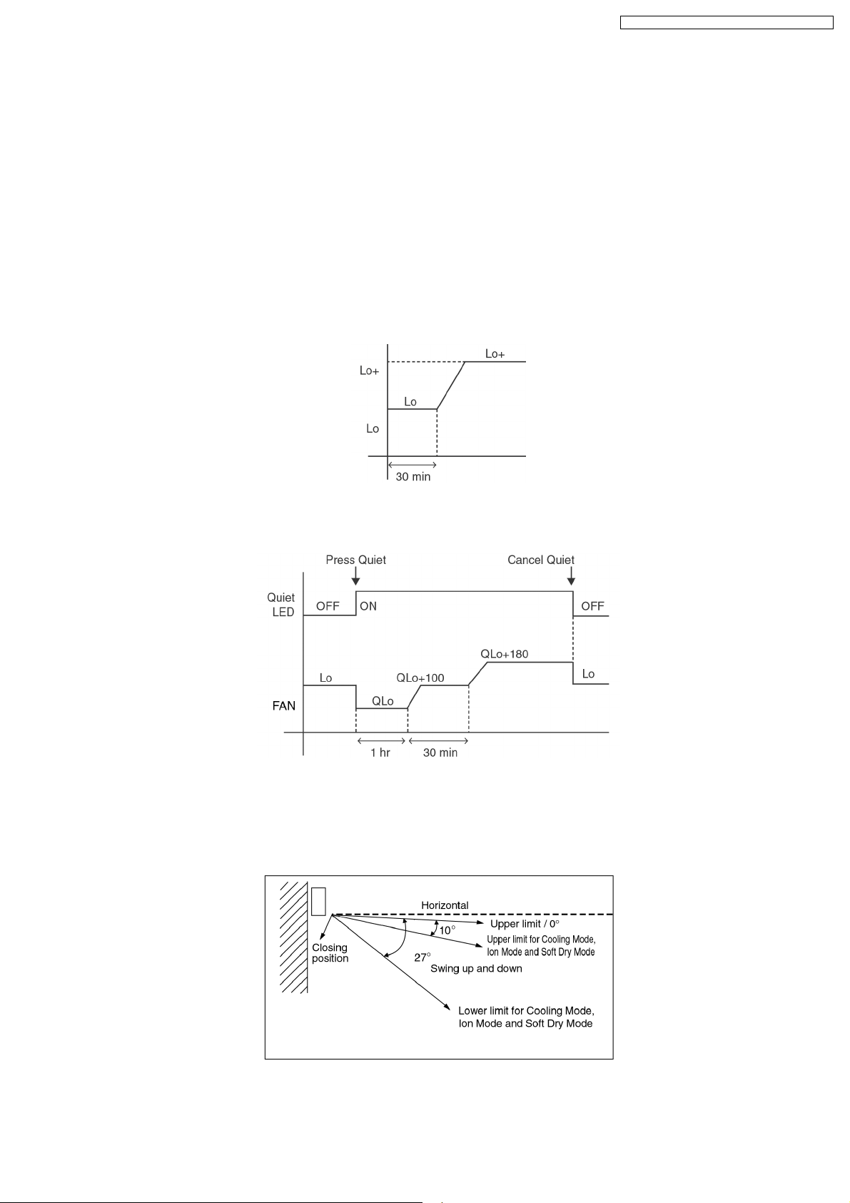
8.5.7. Anti-Dew Formation Control
• Purpose is to prevent dew formation on indoor unit air discharge area.
• When room temperature is constant (±1°C) the following conditions occur for 30 minutes continuously, anti-dew formation will
activate:
− Remote Control setting temperature is less than 25°C.
− Compressor is on.
− Cooling operation mode.
− Indoor Fan motor operate at Low fan speed or QLo.
• This control is cancelled immediately when above condition is changed.
• Anti-Dew formation is control by:
1. Increasing Air Flow Volume
a. Lo fan speed
Lo fan speed is changed to Lo+ after 30 min to prevent dew formation.
b. QLo fan speed
Dew formation may occurs at QLo cool, therefore QLo cool is operated only 1 hr 30 min (1 hr QLo, 30 min QLo +100
rpm). After that, it operates at QLo +180rpm (However Quiet LED remains on).
2. Norrowing
Vertical Airflow Direction
− During Anti-dew condensation prevention, Airflow Direction Auto-control angle change from 10° - 38° to 10° - 27° under
Cooling and Soft Dry operation mode.
21
Page 22
CS-A18DKD CU-A18DKD / CS-A24DKD CU-A24DKD
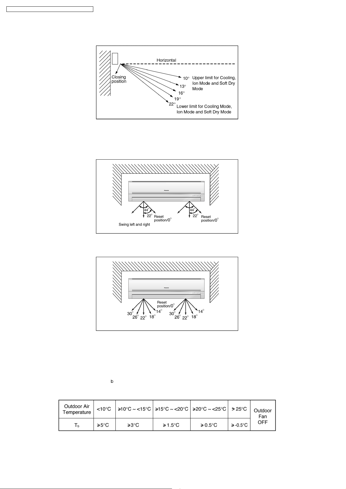
− During Anti-dew condensation prevention, Airflow Direction Manual control angle change from 10°, 14°, 18°, 22°, 27° to
10°, 13°, 16°, 19°, 22° under Cooling and Soft Dry operation mode.
3. Narrowing
Horizontal Airflow Direction
− During Anti-dew condensation prevention, Airflow Direction Auto-control angle change from 0° - 44° to 14° - 30° under
Cooling and Soft Dry operation mode.
− During Anti-dew condensation prevention, Airflow Direction Manual control angle change from 0°, 11°, 22°, 33°, 44° to
14°, 18°, 22°, 26°, 30° under Cooling and Soft Dry operation mode.
(For 8.5.8. to 8.5.13. information applies only to Heating Operation)
8.5.8. Overload Protection Control
• Outdoor Fan Control
− If the temperature of the Outdoor Heat Exchanger less than -3°C, Outdoor Fan is ON. The Outdoor Fan stop, when Outdoor
Heat Exchanger temperature is T
The Outdoor Fan restarts when the indoor heat exchanger temperature falls to 49°C.
or more according to Outdoor Air Temperature region as table below:
− During starting of Heating mode and after deice, Outdoor Fan ON for 90 sec. (Hi).
22
Page 23
CS-A18DKD CU-A18DKD / CS-A24DKD CU-A24DKD
• Compressor high pressure protection
− If the indoor heat exchanger becomes 68°C or more, the compressor will stop and restart automatically.
− Time Delay Safety Control is activated before the compressor restart.
8.5.9. 4-Way Valve Control
• 4-way valve always on during Heating operation. (except deicing operation)
• When the unit is switched off by remote control during Heating operation, the 4-way valve stay at Heating position for 5 minutes.
• This is to prevent the refrigerant flow process sound for being occur.
8.5.10. Outdoor Fan Motor Control
• When compressor stops (reaches room temperature), outdoor fan will operate for 30 seconds (forced operation).
• This is to release the heat and to obtain the lowest pressure as fast as possible.
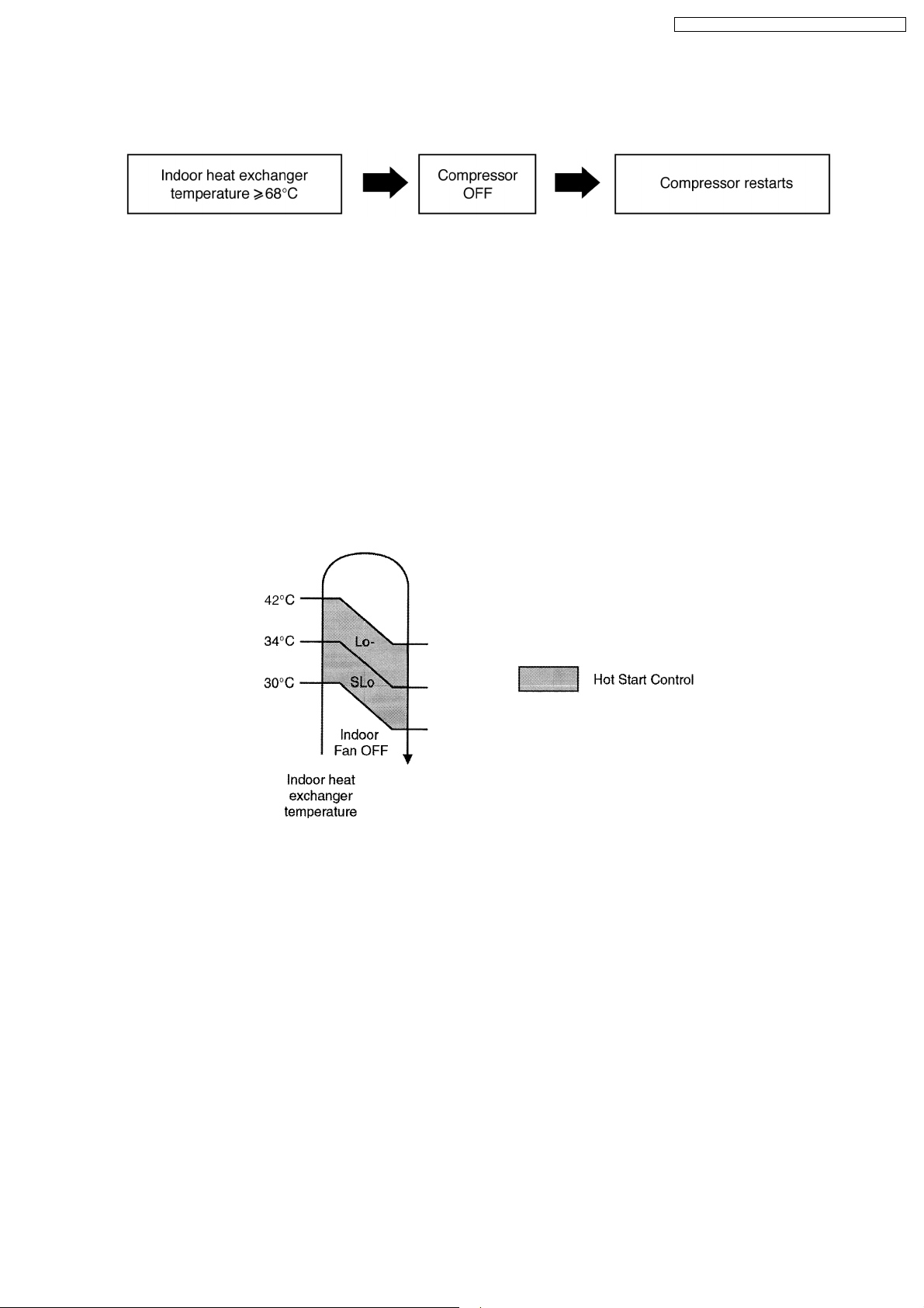
8.5.11. Hot Start Control
• Hot Start Control is to prevent cool air discharge into the room when heating operation start.
• When Heating operation starts, Indoor fan will not start until the indoor heat exchanger reaches 30°C as diagram shown.
• Hot start is completed when indoor heat exchanger rises to 42°C or operation over 4 minutes.
23
Page 24
CS-A18DKD CU-A18DKD / CS-A24DKD CU-A24DKD
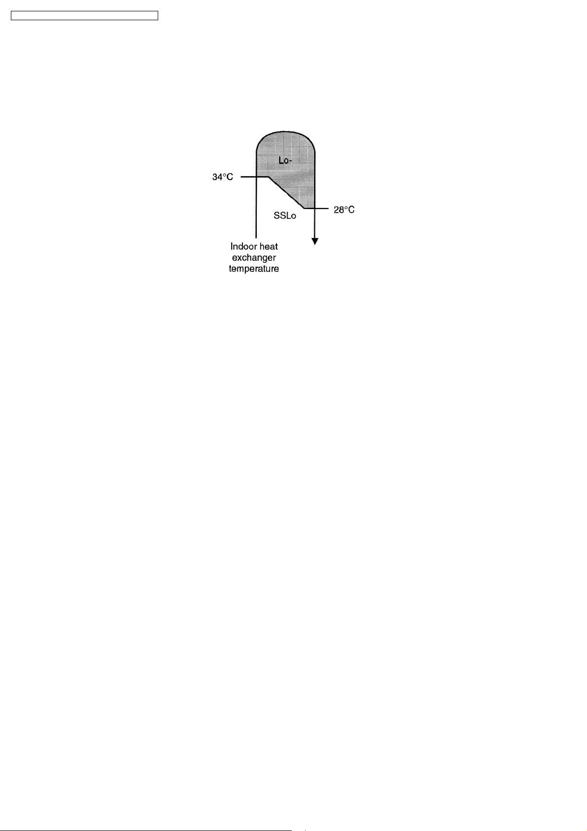
8.5.12. Anti Cold Draft Control
• This operation is to prevent the Cold Draft during Heating mode operation.
• The operation will start when compressor OFF (Thermo OFF) during Heating operation.
• For the first 30 sec. from compressor OFF (Termo OFF), Indoor fan speed will operate accordingly to the Indoor heat exchanger
temperature as shown below:
• After 30 sec. from compressor OFF (thermo OFF), Indoor fan will run at SSLo speed only.
• Anti Cold Draft Control will stop when:
− Intake temperature < set temperature. (Time Delay Safety Control 4 minutes waiting is valid)
− 30 Minutes Time Save Control activates.
8.5.13. Deicing Control
Deice starts to prevent frosting at outdoor heat exchanger.
• Normal Deicing
Deice operations detection commences after 60 minutes of Heating operation starts or 60 minutes after previous deice
operation. If the TRS (Thermal Read Switch) senses the outdoor piping temperature drops to -4°C (TRS CLOSE) or less for 50
sec. continuously during compressor is in operation, deice will start.
(There is no detection during Outdoor Fan stops.)
• Overload Deicing
During heating operation, if the outdoor Fan OFF duration (due to overload control) is accumulated up to 60 minutes and after
compressor starts for 1 minutes, deicing starts.
• Deicing ends when
1. 12 minutes after deicing operation starts;
2. The outdoor piping temperature rises to 12°C.
• After deicing operation, compressor stops for 30 seconds and 4-way valve stays at cooling position for 10 seconds.
24
Page 25
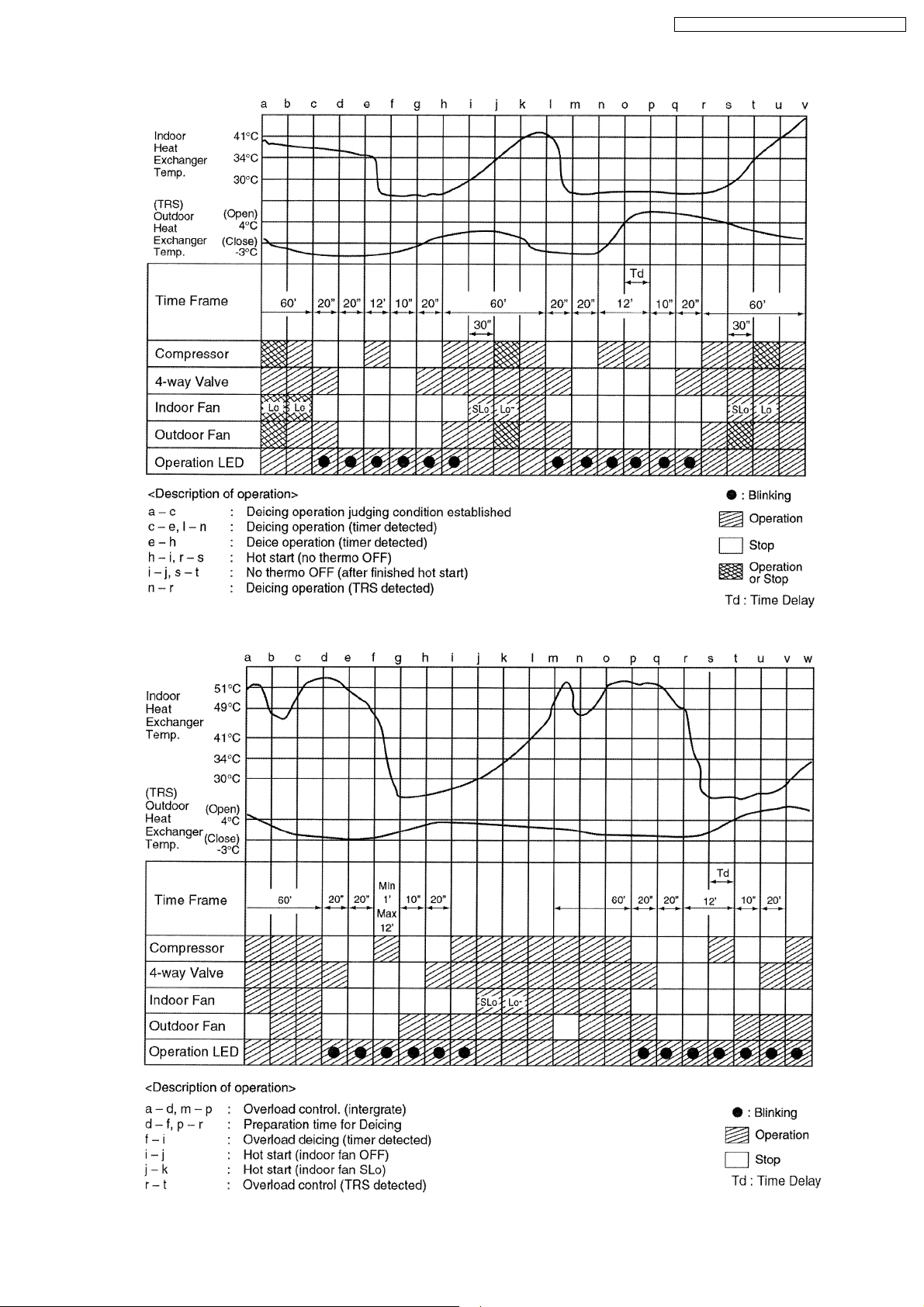
Normal Deicing Time Diagram
CS-A18DKD CU-A18DKD / CS-A24DKD CU-A24DKD
Overload Deicing Time Diagram
25
Page 26
CS-A18DKD CU-A18DKD / CS-A24DKD CU-A24DKD
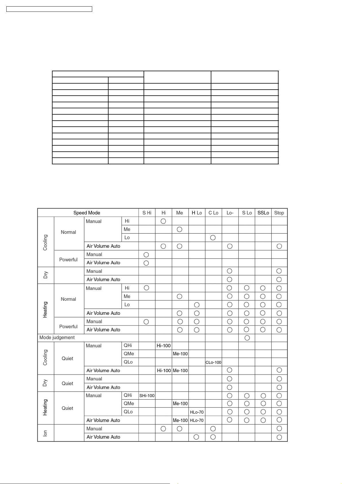
8.6. Indoor Fan Speed Control
• Indoor Fan Speed can be set using remote control.
8.6.1. Fan Speed Rotation Chart
Fan Speed CS-A18DKD CS-A24DKD
Cool, Dry Heat
SHi Hi 1460 1650
Hi - 1400 1590
Me Me 1320 1480
Lo+ Lo 1270 1380
Lo - 1190 1280
Lo- Lo- 980 1070
SLo SLo 760 830
- SSLo 300 300
QSHi QHi 1360 1550
QHi - 1300 1490
QMe QMe 1220 1380
- QLo 1170 1280
QLo - 1090 1180
8.6.2. Automatic Fan Speed Control
• When set to Auto Fan Speed, the fan speed is adjusted between maximum and minimum setting as shown in the table.
− Fan speed rotates in the range of Hi and Me.
− Deodorizing Control will be activated.
26
Page 27

CS-A18DKD CU-A18DKD / CS-A24DKD CU-A24DKD
• Auto Fan Speed during Cooling operation:
1. Indoor fan will rotate alternately between off and on as shown in below diagram.
2. At the beginning of each compressor start operation, indoor fan will increase fan speed gradually for deodorizing purpose.
3. For the first time the compressor operate, indoor fan will be switched to Hi fan speed from SLo after 70 seconds from the
start of compressor. This cause the room temperture to achieve the setting temperature quickly.
4. During compressor stop, indoor fan will operate at SLo for the beginning 20 seconds to prevent higher volume of refrigerant
in liquid form returning to the compressor.
5. After the compressor at turn off condition for 3 minutes, indoor fan will start to operate at SLo to circulate the air in the room.
This is to obtain the actual reading of the intake air temperature.
6. When the compressor resume operation, indoor fan will operate at Me fan speed (after 70 seconds from the restart of
compressor) to provide comfort and lesser noise environment.
• Auto Fan Speed during Soft Dry operation:
1. Indoor fan will rotate alternately between off and Lo-.
2. At the beginning of each compressor start operation, indoor fan will increase fan speed gradually for deodorizing purpose.
3. When compressor at turn off condition for 6 minutes, indoor fan will start fan speed at Lo- to circulate the air in the room.
This is to obtain the actual reading of intake air temperature.
• Auto Fan Speed during Heating operation.
1. Indoor fan will rotate in the range of SLo → Me according to the heat exchanger temperature.
27
Page 28

CS-A18DKD CU-A18DKD / CS-A24DKD CU-A24DKD
8.6.3. Manual Fan Speed Control
• Manual fan speed adjustment can be carried out by using the Fan Speed selection button at the remote control.
• There are 3 types of fan speed settings: Lo, Me, Hi.
8.7. Outdoor Fan Speed Control
• There is only one speed for outdoor fan motor.
• When the air conditioner is turned on, the compressor and the outdoor fan will operate simultaneously.
• Likewise, both compressor and outdoor fan will stop at the same time if the unit is turned off.
8.8. Vertical Airflow Direction Control
8.8.1. Auto Control
(Cooling and Soft Dry Operation condition)
• When the vertical airflow direction is set to Auto using the
remote control, the louver swings up and down as shown in
the diagram.
• When stop operation using the remote control, the
discharge vent is reset, and stop at the closing position.
• During Cooling operation or Soft Dry operation, indoor fan
motor may stop to rotate at certain periods. At that
condition, the louver will stop swinging and rest at the upper
limit.
(Heating Operation condition)
• When the intake air temperature reaches 38°C, the louver
is changed from upper to lower limit. When the intake air
temperature falls to 35°C, the louver is changed from louver
to upper limit.
Cooling and Soft Dry Operation
Heating Operation
8.8.2. Manual Control
• When the vertical airflow direction is set to Manual using the remote control, the automatic airflow is released and the airflow
direction louver move up and down in the range shown in the diagram.
• The louver can be adjusted by pressing the button to the desired louver position.
• When stop operation using the remote control, the discharge vent is reset, and stop at the closing position.
28
Page 29

8.9. Horizontal Airflow Direction Control
8.9.1. Auto Control
• When the horizontal airflow direction is set to Auto using the
remote control, the vanes swings left and right as shown in
the diagram.
• When stopped with remote control, the discharge vane is
reset, and stop at the reset position.
• During Cooling operation or Soft Dry operation, indoor fan
motor may stop to rotate at certain periods. At that
condition, the vane will stop swinging and rest at 22° angle.
8.9.2. Manual Control
• When the horizontal airflow direction is set to Manual using
the remote control, the automatic airflow is released and the
airflow direction vane move left and right in the range shown
in the diagram.
The louver can be adjusted by pressing the button to the
desired vane position.
• When stopped with remote control, the vanes is reset, and
stopped at reset position.
CS-A18DKD CU-A18DKD / CS-A24DKD CU-A24DKD
29
Page 30

CS-A18DKD CU-A18DKD / CS-A24DKD CU-A24DKD
8.10. Powerful Operation
• The Powerful operation is to achieve the setting temperature quickly.
(Cooling and Soft Dry Operation condition)
• When Powerful operation is set, the setting temperature will be automatically decreased 3°C internally against the present
setting temperature (Lower temperature limit: 16°C).
• This operation automatically will be running under SHi Fan Speed (Cooling), Lo- Fan Speed (Soft Dry).
• Vertical Airflow Direction:-
- In “Manual” setting, the vane will automatically shift down 10° lower than previous.
- In “Auto” setting, the vane will automatically swing up and down. However the lower limit will be shifted 10° downward.
(Heating Operation condition)
• When Powerful operation is set, the setting temperature will be automatically increased 3°C against the present setting
temperature (Higher temperature: 30°C).
• The Fan Speed will shift as shown below:
• Vertical Airflow Direction:-
- In “Manual” setting, the vane will automatically shift down 5° lower than previous setting.
- In “Auto” setting, the vane will automatically shift between upper and lower limit depending on the intake air temperature as
Heating Mode, Airflow Direction Auto-Control. However the upper and lower limit will be shifted 5° downward.
• Powerful Mode will operate for 15 minutes only and operation will shift back to previous setting mode.
• Powerful operation stops when:-
- Powerful operation has operate for 15 minutes.
- Powerful button is pressed again.
- Quiet button is pressed.
- Stopped by OFF/ON operation button.
- Timer OFF activates.
- Operation mode is changed.
8.11. Quiet Operation
• The Quiet operation is to provide quiet cooling/heating operation condition compare to normal operation.
(Cooling and Soft Dry Operation condition)
• Once the Quiet Mode is set at the remote control, the Quiet Mode LED illuminated. The sound level will reduce either around
2 dB(A) for Lo fan speed or 3 dB(A) for Hi/Me fan speed against the present sound level operation.
• Dew formation become severe at Quiet Lo cool, therefore Quiet Lo cool is operated only 1hr 30 min (1hr QLo, 30 min QLo +
50rpm). After that, it goes back to Lo cool (However Quiet LED remains on).
30
Page 31

• Manual Airflow Direction:-
− RPM control during Lo cool
− RPM control during Hi & Me cool
CS-A18DKD CU-A18DKD / CS-A24DKD CU-A24DKD
• Auto Airflow Direction:-
(Heating Operation condition)
• When the Quiet Mode is set at the remote control, Quiet Mode LED illuminates. The sound level will reduce either around 2
dB(Lo) or 3 dB(Hi, Me), against the present sound level operation.
• Quiet setting of fan speed rpm refer to Indoor Fan Speed Control.
• Manual Airflow Direction:-
− Rpm control during Lo, Me & Hi Cool
31
Page 32

CS-A18DKD CU-A18DKD / CS-A24DKD CU-A24DKD
• Auto Airflow Direction:-
− Rpm control depends on the piping air temperature sensor of Indoor heat exchanger
• Quiet operation stops when:-
− Quiet/Powerful button is pressed again.
− Stopped by OFF/ON operation button.
− Timer OFF activates.
− Operating mode is changed.
8.12. Ionizer Operation
• The Ionizer operation is to provide fresh air effect to user by producing minus ion in discharge air.
8.12.1. Operation Control
1. Ionizer individual operation
a. When air-conditioner unit is at “OFF” condition (standby) and ION operation button at the remote control is pressed, the
Ionizer and Air Circulation operations will turn on. Only ION LED will illuminates. Power LED maintain off. (1 → 2)
b. Ionizer individual operation can be turned off by pressing the ION button again. (2 → 1)
c. Fan speed can be adjusted later by customer during this operation.
32
Page 33

CS-A18DKD CU-A18DKD / CS-A24DKD CU-A24DKD
d. Vertical airflow direction can be adjusted using remote control during Ionizer individual operation.
e. During Ionizer individual operation, operated mode (Auto, Cool, Dry, Heat) can be activated by turning on the OFF/ON
operation button. (2 → 4)
f. If power failure occur during Ionizer individual operation, after power resume, Ionizer operation will be activated immediately.
g. When the Ionizer circuit feedback process error occur for 24 times (about 11hr 30 min.), Ionizer and Air Circulation
operations will turn off with ION LED blinks continuously.
(For details, please refer to Ionizer Error detection control)
2. Operation mode & Ionizer operation.
a. When air-conditioner unit is at “ON” condition and ION operation button at the remote control is pressed, the Ionizer
operation will turn on. ION & Power LED will illuminate. (3 → 4)
b. Ionizer operation stops when:
• ION operation button is press again.
• Stopped by OFF/ON operation button.
• Timer OFF activates.
• Ionizer circuit feedback signal shows error.
c. Ionizer operation status is not memorised when the air conditioner has been switched off. The air-conditioner will operate
without ionizer operation when it is turned on again. However, if power failure occurs during Ionizer operation together with
Cooling operation, air-conditioner will start to operate at Cooling operation with Ionizer operation when the power is
resumed.
8.12.2. Error Detection Control
• The error detection control is to inform user that error occurs at ionizer system and repairing job will be needed.
• There are two types of error detection control:
a. When Ionizer is ON
− If ionizer feedback = Lo for 24 times within 11hr 30min, ION LED blinks continuously.
b. When ionizer is OFF
− If ionizer feedback = Hi, ION LED blinks continuously.
• During ionizer at breakdown condition, if ionizer feedback voltage = Lo (become normal), ION LED will stop blinking.
• The error detection control can be reset by:
i) Pressing the OFF/ON operation button to switch the operation OFF.
ii) Pressing the Auto Operation button to force the operation OFF.
iii) Setting the OFF Timer to stop the operation (Not applicable when ionizer is OFF).
8.13. Timer Control
8.13.1. Delay ON Timer
• When the Delay ON Timer is set by using the remote control, the unit will start to operate slightly before the set time, so that
the room will reach nearly to the set temperature by the set time.
• For Cooling and Soft Dry operation, the operation will start 15 minutes before the set time.
• For Heating operation, the operation will start 30 minutes before the set time.
• For Automatic operation, the indoor fan will operate at SLo speed for 20 seconds, 15 minutes before the set time to detect the
intake air temperature to determine the operation mode. The operation indication lamp will blink at this time.
8.13.2. Delay OFF Timer
• When the Delay OFF Timer is set by using the remote control, the unit will stop operate according to the desired setting.
Notes:
1. By pressing OFF/ON operation button, the Delay ON Timer or Delay OFF Timer setting will not be cancelled.
2. To activate the previous timer setting, press SET/CANCEL button once again.
33
Page 34

CS-A18DKD CU-A18DKD / CS-A24DKD CU-A24DKD
8.14. Random Auto Restart Control
• If there is a power failure during operation, the air conditioner will automatically restart after 3 to 4 minutes when the power is
resumed.
• It will start with previous operation mode and airflow direction.
• If there are more than one air conditioner unit in operation and power failure occur, restart time for each unit to operate will be
decided randomly using 4 parameters:- intake air temperature, setting temperature, fan speed and air swing louver position.
• This Random Auto Restart Control is not available when Timer is set.
• This control can be omitted by open the circuit of JX2. (Refer Circuit Diagram)
8.15. Remote Control Signal Receiving Sound
• Long beep sound will be heard when:-
− Stopping the air conditioner using OFF/ON operation button.
− Stopping the Quiet Mode.
− Stopping the Powerful Mode.
− Stopping the Ion Mode.
• Short beep sound will be heard for other setting.
• To switch off the beep sound:-
Press the “Auto Operation Button” (behind the front grille) continuously for 10 seconds or more (“beep” “beep” will be heard at
the 10th second). Repeat the above if you want to switch on the beep sound.
However, if the “Automatic Operation Button” has been pressed the Automatic operation will be activated. If you do not require
this operation, you may change it by using the remote control.
34
Page 35

9 Operating Instructions
CS-A18DKD CU-A18DKD / CS-A24DKD CU-A24DKD
35
Page 36

CS-A18DKD CU-A18DKD / CS-A24DKD CU-A24DKD
36
Page 37

CS-A18DKD CU-A18DKD / CS-A24DKD CU-A24DKD
37
Page 38

CS-A18DKD CU-A18DKD / CS-A24DKD CU-A24DKD
38
Page 39

CS-A18DKD CU-A18DKD / CS-A24DKD CU-A24DKD
39
Page 40

CS-A18DKD CU-A18DKD / CS-A24DKD CU-A24DKD
40
Page 41

CS-A18DKD CU-A18DKD / CS-A24DKD CU-A24DKD
10 Installation Instructions
Required tools for Installation Works
1. Philips screw driver 5. Spanner 9. Gas leak detector 13. Multimeter
2. Level gauge 6. Pipe cutter 10. Measuring tape 14. Torque wrench
3. Electric drill, hole core drill
(ø70 mm)
4. Hexagonal wrench (4 mm) 8. Knife 12. Megameter 16. Gauge manifold
7. Reamer 11. Thermometer 15. Vacuum pump
10.1. Safety Precautions
• Read the following “SAFETY PRECAUTIONS” carefully before installation.
• Electrical work must be installed by a licensed electrician. Be sure to use the correct rating of the power plug and main circuit
for the model to be installed.
• The caution items stated here must be followed because these important contents are related to safety. The meaning of each
indication used is as below. Incorrect installation due to ignoring of the instruction will cause harm or damage, and the
seriousness is classified by the following indications.
This indication shows the possibility of causing death or serious injury.
18 N.m (1.8 kgf.m)
55 N.m (5.5 kgf.m)
65 N.m (6.5 kgf.m)
This indication shows the possibility of causing injury or damag e to properties only.
The items to be followed are classified by the symbols:
Symbol with background white denotes item that is PROHIBITED from doing.
• Carry out test running to confirm that no abnormality occurs after the installation. Then, explain to user the operation, care and
maintenance as stated in instructions. Please remind the customer to keep the operating instructions for future reference.
1. Engage dealer or specialist for installation. If installation done by the user is defective, it will cause water leakage, electrical shock or fire.
2. Install according to this installation instruction strictly. If installation is defective, it will cause water leakage, electrical shock or fire.
3. Use the attached accessories parts and specified parts for installation. Otherwise, it will cause the set to fall, water leakage, fire or
electrical shock.
4. Install at a strong and firm location which is able to withstand the set’s weight. If the strength is not enough or installation is not properly
done, the set will drop and cause injury.
5. For electrical work, follow the local national wiring standa rd, regulation and this installation instructions. An independent circuit and single
outlet must be used. If electrical circuit capacity is not enough or defect found in electrical work, it will cause electrical shock or fire.
6. Use the specified cable (2.5 mm2) and connect tightly for indoor/outdoor connection. Conne ct tightly and clamp the cable so that no
external force will be acted on the terminal. If connection or fixing is not perfect, it will cause heat-u p or fire at the connection.
7. Wire routing must be properly arranged so that control board cover is fixed properly. If control board cover is not fixed perfectly, it will
cause heat-up at connection point of terminal, fire or electrical shock.
8. When carrying out piping connection, take care not to let air substances other than the specified refrigerant go into refrigeration cycle.
Otherwise, it will cause lower capacity, abnorm al high pressure in the refrigeration cycle, explosion and injury.
9. Do not damage or use unspecified power supply cord. Otherwise, it will cause fire or electrical shock.
10. Do not modify the length of the power supply cord or use of the extension cord, and do not share the single outlet with
other electrical applian ces. Otherwise, it will cause fire or electrical shock.
41
Page 42

CS-A18DKD CU-A18DKD / CS-A24DKD CU-A24DKD
1. This equipment must be earthed. It may cause electrical shock if grounding is not perfect.
2. Do not install the unit at place where leakage of flammable gas may occur. In case gas leaks and accumulates at
surrounding of the unit, it may cause fire.
3. Carry out drainage piping as mentioned in installation instructions. If drainage is not perfect, water may enter the room and damage the
furniture.
1. Selection of the installation location.
Select an installation location which is rigid and strong enough to support or hold the unit, and select a location for easy maintenance.
2. Power supply connection to the air conditioner.
Connect the power supply cord of the air conditioner to the mains using one of the following method.
Power supply point shall be the place where there is ease for access for the power disconnection in case of emergency.
In some countries, permanent connection of this air conditioner to the power supply is prohibited.
1. Power supply connection to the receptacle using a power plug.
Use an approved 16A power plug with earth pin for 2.0HP (A18DK) and 20A for 2.5HP (C24DK, A24DK) for the connection to the
receptacle.
2. Power supply connection to a circuit breaker for the permanent connection. Use an approved 16A circuit breaker for 2.0HP (A18DK)
and 20A for 2.5HP (C24DK, A24DK) for the permanent connection. It must be a double pole switch with a minimu m 3.5 mm contact
gap.
3. Do not release refrigerant.
Do not release refrigerant during piping work for installation, re-installation and during repairing a refrigeration parts. Take care of the
liquid refrigerant, it may cause frostbite.
4. Installation work.
It may need two people to carry out the installation work.
5. Do not install this appliance in a laundry room or other location where water may drip from the ceiling, etc.
42
Page 43

Attached accessories
Applicable piping kit
CZ-4F5, 7, 10AN (A18DK)
CZ-52F5, 7, 10AN (C24DK, A24DK)
CS-A18DKD CU-A18DKD / CS-A24DKD CU-A24DKD
Indoor/Outdoor Unit Installation Diagram
SELECT THE BEST LOCATION
INDOOR UNIT
• There should not be any heat source or steam near the
unit.
• There should not be any obstacles blocking the air
circulation.
• A place where air circulation in the room is good.
• A place where drainage can be easily done.
• A place where noise prevention is taken into
consideration.
• Do not install the unit near the door way.
• Ensure the spaces indicated by arrows from the wall,
ceiling, fence or other obstacles.
• Recommended installation height for indoor unit shall be
at least 2.3 m.
OUTDOOR UNIT
• If an awning is built over the unit to prevent direct
sunlight or rain, be careful that heat radiation from the
condenser is not obstructed.
• There should not be any animal or plant which could be
affected by hot air discharged.
• Keep the spaces indicated by arrows from wall, ceiling,
fence or other obstacles.
• Do not place any obstacles which may cause a short
circuit of the discharged air.
• If piping length is over 7.5m, additional refrigerant
should be added as shown in the table.
• This illustration is for explanation purposes only.
The indoor unit will actually face a different way.
43
Page 44

CS-A18DKD CU-A18DKD / CS-A24DKD CU-A24DKD
10.2. Indoor Unit
10.2.1. SELECT THE BEST LOCATION
(Refer to “Select the best location”
section)
10.2.2. HOW TO FIX INSTALLATION
PLATE
The mounting wall is strong and solid enough to prevent it from
the vibration.
10.2.3. TO DRILL A HOLE IN THE WALL
AND INSTALL A SLEEVE OF
PIPING
1. Insert the piping sleeve to the hole.
2. Fix the bushing to the sleeve.
3. Cut the sleeve until it extrudes about 15 mm from the wall.
Caution
When the wall is hollow, please be sure to use the
sleeve for tube ass’y to prevent dangers caused by
mice biting the connecting cable.
4. Finish by sealing the sleeve with putty or caulking
compound at the final stage.
The centre of installation plate should be at more than 550 mm
at right and left of the wall.
The distance from installation plate edge to ceiling should more
than 67 mm.
From installation plate left edge to unit’s left side is 47 mm.
From installation plate right edge to unit’s right is 73 mm.
:
For left side piping, piping connection for liquid should be
about 126 mm from this line.
:
For left side piping, piping connection for gas should be
about 174 mm from this line.
:
For left side piping, piping connection cable should be
about 984 mm from this line.
1. Mount the installation plate on the wall with 5 screws or
more.
(If mounting the unit on the concrete wall, consider using
anchor bolts.)
• Always mount the installation plate horizontally by
aligning the marking-off line with the thread and using a
level gauge.
2. Drill the piping plate hole with ø70 mm hole-core drill.
• Line according to the arrows marked on the lower left
and right side of the installation plate. The meeting point
of the extended line is the centre of the hole. Another
method is by putting measuring tape at position as
shown in the diagram above. The hole centre is
obtained by measuring the distance namely 150 mm
and 125 mm for left and right hole respectively.
• Drill the piping hole at either the right or the left and the
hole should be slightly slanted to the outdoor side.
10.2.4. INDOOR UNIT INSTALLATION
1. For the right rear piping
2. For the right and right bottom piping
44
Page 45

3. For the embedded piping
CS-A18DKD CU-A18DKD / CS-A24DKD CU-A24DKD
45
Page 46

CS-A18DKD CU-A18DKD / CS-A24DKD CU-A24DKD
10.2.5. CONNECT THE CABLE TO THE INDOOR UNIT
1. The inside and outside connecting cable can be connected
without removing the front grille.
2. Connecting cable between indoor unit and outdoor unit
shall be approved polychloroprene sheathed 3 × 2.5 mm
(C24DK) or 5 × 2.5 mm2(A18DK, A24DK) flexible cord,
type designation 245 IEC 57 or heavier cord.
• Ensure the colour of wires of outdoor unit and the
terminal Nos. are the same to the indoor’s respectively.
• Earth lead wire shall be longer than the other lead wires
as shown in the figure for the electrical safety in case of
the slipping out of the cord from the anchorage.
2
• Secure the cable onto the control board with the holder
(clamper).
INSTALLATION OF SUPER ALLERU-BUSTER FILTER
1. Open the front panel.
2. Remove the air filter.
3. Remove Supersonic air purifying device.
4. Open the Supersonic air purifying device frame.
5. Insert the super alleru-buster filter and close the Supersonic
air purifying device frame as shown in illustration at right.
46
Page 47

CS-A18DKD CU-A18DKD / CS-A24DKD CU-A24DKD
HOW TO TAKE OUT FRONT GRILLE
Please follow the steps below to take out front grille if
necessary such as when servicing.
1. Open the intake grille.
2. Set the vertical airflow direction louver to the horizontal
position.
3. Slide down the 3 caps on the front grille as shown in the
illustration below, and then remove the 3 mounting screws.
4. Pull the lower section of the front grille towards you to
remove the front grille.
When reinstalling the front grille, first set the vertical
airflow direction louvers to the horizontal position and
then carry out above steps 2 - 3 in the reverse order.
AUTO SWITCH OPERATION
The below operations will be performed by pressing the
“AUTO” switch.
1. AUTO OPERATION MODE
The Auto operation will be activated immediately once the
Auto Switch is pressed.
2. TEST RUN OPERATION (FOR PUMP DOWN/SERVICING
PURPOSE)
The Test Run operation will be activated if the Auto Switch
is pressed continuously for more than 5 sec. A “beep”
sound will occur at the fifth sec., in order to identify the
starting of Test Run operation.
3. REMOTE CONTROLLER RECEIVING SOUND ON/OFF
The ON/OFF of remote controller receiving sound can be
changed over by the following step:
a. Release the Auto Switch after Test Run operation is
activated.
b. Then, within 20 sec after (a), press Auto Switch for more
than 5 sec.
A “beep” “beep” sound will occur at the fifth sec., then
release the Auto switch.
c. Within 20 sec after (b), press Auto Switch again.
Everytime Auto Switch is pressed (within 20 sec
interval), remote controller receiving sound status will be
reversed between ON and OFF.
Long “beep” sound indicates that remote controller
receiving sound is OFF.
Short “beep” sound indicates that remote controller
receiving sound is ON.
47
Page 48

CS-A18DKD CU-A18DKD / CS-A24DKD CU-A24DKD
10.3. Outdoor Unit
10.3.1. SELECT THE BEST LOCATION
(Refer to “Select the best location” section)
10.3.2. INSTALL THE OUTDOOR UNIT
• After selecting the best location, start installation according
to Indoor/Outdoor Unit Installation Diagram.
1. Fix the unit on concrete or rigid frame firmly and horizontally
by bolt nut. (ø10 mm).
2. When installing at roof, please consider strong wind and
earthquake. Please fasten the installation stand firmly with
bolt or nails.
10.3.3. CONNECTING THE PIPING
Connecting The Piping To Indoor Unit
Please make flare after inserting flare nut (locate at joint portion
of tube assembly) onto the copper pipe. (in case of using long
piping)
Connect the piping
• Align the center of piping and sufficiently tighten the flare
nut with fingers.
• Further tighten the flare nut with torque wrench in specified
torque as stated in the table.
Connecting The Piping To Outdoor Unit
Decide piping length and then cut by using pipe cutter. Remove burrs from cut edge. Make flare after inserting the flare nut
(located at valve) onto the copper pipe.
Align center of piping to valves and then tighten with torque wrench to the specified torque as stated in the table.
CUTTING AND FLARING THE PIPING
1. Please cut using pipe cutter and then remove the burrs.
2. Remove the burrs by using reamer. If burrs is not
removed, gas leakage may be caused.
Turn the piping end down to avoid the metal powder
entering the pipe.
3. Please make flare after inserting the flare nut onto the
copper pipes.
MODEL Piping size (Torque)
Gas Liquid
A18DK 1/2” (55 N.m) 1/4” (18 N.m)
C24DK, A24DK 5/8” (65 N.m) 1/4” (18 N.m)
48
Page 49

10.3.4. EVACUATION OF THE EQUIPMENT
CS-A18DKD CU-A18DKD / CS-A24DKD CU-A24DKD
1. Connect a charging hose with a push pin to the Low side
of a charging set and the service port of the 3-way valve.
• Be sure to connect the end of the charging hose with
the push pin to the service port.
2. Connect the center hose of the charging set to a
vacuum pump with check valve, or vacuum pump and
vacuum pump adaptor.
3. Turn on the power switch of the vacuum pump and
make sure that the needle in the gauge moves from 0
cmHg (0 Mpa) to -76 cmHg (-0.1 Mpa). Then evacuate
the air approximately ten minutes.
4. Close the Low side valve of the charging set and turn off
Note : BE SURE TO FOLLOW THIS PROCEDURE IN
ORDER TO AVOID REFRIGERANT GAS LEAKAGE.
5. Disconnect the charging hose from the vacuum pump
and from the service port of the 3-way valve.
6. Tighten the service port caps of the 3-way valve at a
torque of 18 N.m with a torque wrench.
7. Remove the valve caps of both of the 2-way valve and
3-way valve. Position both of the valves to “OPEN”
using a hexagonal wrench (4 mm).
8. Mount valve caps onto the 2-way valve and the 3-way
valve.
• Be sure to check for gas leakage.
the vacuum pump. Make sure that the needle in the
gauge does not move after approximately five minutes.
CAUTION
• If gauge needle does not move from 0 cmHg (0 Mpa) to -76 cmHg (-0.1 Mpa), in step
• If the leak stops when the piping connections are tightened further , continu e working from step
• If the leak does not stop when the connections are retightened, repair the location of leak.
• Do not release refrigerant during piping work for installation and reinstallation. Take care of the liquid refrigerant , it may cause frostbite.
above take the following measure.-
.
10.3.5. CONNECT THE CABLE TO THE OUTDOOR UNIT
1. Remove the control board cover from the unit by loosening the screw.
2
2. Connecting cable between indoor unit and outdoor unit shall be approved polychloroprene sheathed 3 × 2.5 mm
5 × 2.5 mm
2
( A18CK, A24DK) flexible cord, type designation 245 IEC 57 or heavier cord.
(C24DK) or
3. Secure the cable onto the control board with the holder (clamper).
4. Attach the control board cover to the original position with the screw.
49
Page 50

CS-A18DKD CU-A18DKD / CS-A24DKD CU-A24DKD
10.3.6. PIPE INSULATION
1. Please carry out insulation at pipe connection portion as mentioned in Indoor/Outdoor Unit Installation Diagram. Please wrap
the insulated piping end to prevent water from going inside the piping.
2. If drain hose or connecting piping is in the room (where dew may form), please increase the insulation by using POLY-E FOAM
with thickness 6 mm or above.
DISPOSAL OF OUTDOOR UNIT DRAIN WATER
• If a drain elbow is used, the unit should be placed on a
stand which is taller than 3 cm.
• If the unit is used in an area where temperature falls below
0°C for 2 or 3 days in succession, it is recommended not to
use a drain elbow, for the drain water freezes and the fan
will not rotate.
CHECK THE DRAINAGE
• Open front panel and remove air filters.
(Drainage checking can be carried out without removing the
front grille.)
• Pour a glass of water into the drain tray-styrofoam.
• Ensure that water flows out from drain hose of the indoor
unit.
EVALUATION OF THE PERFORMANCE
• Operate the unit at cooling operation mode for fifteen
minutes or more.
• Measure the temperature of the intake and discharge air.
• Ensure the difference between the intake temperature and
the discharge is more than 8°C.
NOTE:
These equipment shall be connected to a suitable mains network
with a main impedance less than the following:
CS/CU-C24DKD:0.13 Ω CS/CU-A24DKD:0.06 Ω
CHECK ITEMS
Is there any gas leakage at flare nut connections?
Has the heat insulation been carried out at flare nut
connection?
Is the connecting cable being fixed to terminal board firmly?
Is the connecting cable being clamped firmly?
Is the drainage OK?
(Refer to “Check the drainage” section)
Is the earth wire conne ction properly done?
Is the indoor unit properly hooked to the installation plate?
Is the power supply voltage complied with rated value?
Is there any abnormal sound?
Is the cooling operation normal?
Is the thermostat operation normal?
Is the remote control’s LCD operation normal?
Is the super alleru-buster filter is installed?
50
Page 51

11 2-way, 3-way Valve
2-way Valve (Liquid Side) 3-way Valve (Gas Side)
Works Shaft Position Shaft Position Service Port
Shipping Close Close Close
CS-A18DKD CU-A18DKD / CS-A24DKD CU-A24DKD
(With valve cap) (With valve cap) (With cap)
Evacuation Close Close Open
(Installation and (Counter-Clockwise) (Clockwise) (Push-pin)
Re-installation)
Operation Open Open Close
(With valve cap) (With valve cap) (With cap)
Pumping down Close Open Open
(Transferring) (Clockwise) (Counter-Clockwise) (Connected manifold
Evacuation Open Open Open
(Servicing) With vacuum pump
Gas charging Open Open Open
(Servicing) (With charging cylinder)
Pressure check Open
(Servicing) Open Open (Connected manifold
Gas releasing Open
(Servicing) Open Open (Connected manifold
gauge)
gauge)
gauge)
51
Page 52

CS-A18DKD CU-A18DKD / CS-A24DKD CU-A24DKD
11.1. Evacuation of the Equipment (For Europe & Oceania Destination)
11.1.1. Evacuation of Installation
WHEN INSTALLING AN AIR CONDITIONER, BE SURE TO
EVACUATE THE AIR INSIDE THE INDOOR UNIT AND PIPES
in the following procedure.
If air remain in the indoor unit and refrigeration pipes, it will
affect the compressor, reduce to cooling capacity, and could
lead to a malfunction.
Procedure:
1. Connect a charging hose with a push pin to the Low
side of a charging set and the service port of a 3-way
valve.
• Be sure to connect the end of the charging hose with the
push pin to the service port.
2. Connect the centre hose of the charging set to a
vacuum pump.
3. Turn on the power switch of the vacuum pump and
make sure that the needle in the gauge moves from 0
MPa (0 cmHg) to -0.1 MPa (-76 cmHg). Then evacuate
the air for approximately ten minutes.
4. Close the Low side valve of the charging set and turn
off the vacuum pump. Make sure that the needle in the
gauge does not move after approximately five minutes.
BE SURE TO TAKE THIS PROCEDURE IN ORDER TO
AVOID GAS LEAKAGE.
5. Disconnect the charging hose from the vacuum pump
and from the service port of the 3-way valve.
6. Tighten the service port cap at a torque of 18 N.m with
a torque wrench.
7. Remove the valve caps of the 2-way valve and the 3-
way valve. Position both of the valves to “open” using
a hexagonal wrench (4 mm).
8. Mount the valve caps onto the 2-way and 3-way valves.
• Be sure to check for gas leakage.
Caution
If gauge needle does not move from 0 cmHg to -76
cmHg in step (3) above, take the following measures:
If the leaks stop when the piping connections are
tightened further, continue working from step (3).
If the leaks do not stop when the connections are
retightened, repair the location of the leak.
52
Page 53

11.1.2. Pumping down
CS-A18DKD CU-A18DKD / CS-A24DKD CU-A24DKD
Procedure:
1. Confirm that both the 2-way and 3-way valves are set to
the opened position.
• Remove the valve stem caps and confirm that the valve
stems are in the opened position.
• Be sure to use a hexagonal wrench to operate the valve
stems.
2. Operate the unit for 10 to 15 minutes.
3. Stop operation and wait for 3 minutes, then connect the
charge set to the service port of the 3-way valve.
• Connect the charge hose with the push pin to the Gas
service port.
4. Air purging of the charge hose.
• Open the low-pressure valve on the charge set slightly
to purge air from the charge hose.
5. Set the 2-way valve to the closed position.
6. Operate the air conditioner at the cooling cycle and
stop it when the gauge indicates 0 MPa (0 kg/cm
2
G).
If the unit cannot be operated at the cooling condition
(weather is rather cool), short the Pumping Down pins
on the Main Control P.C.B.
(Simply press the pumping down button if it is
equipped.)
So that the unit can be operated.
7. Immediately set the 3-way valve to the closed position.
• Do this quickly so that the gauge ends up indicating 0.1
MPa (1 kg/cm
2
G) to 0.3 MPa (3 kg/cm2G).
8. Use refrigerant reclaiming equipment to collect
refrigerant from indoor unit and pipes.
9. Disconnect the charge set, and mount the 2-way and 3-
way valve’s stem caps and the service port caps.
• Use a torque wrench to tighten the service port cap to a
torque of 18 N.m.
• Be sure to check for gas leakage.
10. Disconnect pipes from indoor unit and outdoor unit.
53
Page 54

CS-A18DKD CU-A18DKD / CS-A24DKD CU-A24DKD
11.1.3. Evacuation of Re-installation
WHEN REINSTALLING AN AIR CONDITIONER, BE SURE TO
EVACUATE THE AIR INSIDE THE INDOOR UNIT AND PIPES
in the following procedure.
If air remain in the indoor unit and refrigeration pipes, it will
affect the compressor, reduce to cooling capacity, and could
lead to a malfunction.
Procedure:
1. Connect a charging hose with a push pin to the Low
side of a charging set and the service port of the 3-way
valve.
• Be sure to connect the end of the charging hose with the
push pin to the service port.
2. Connect the centre hose of the charging set to a
vacuum pump.
3. Turn on the power switch of the vacuum pump and
make sure that the needle in the gauge moves from 0
MPa (0 cmHg) to -0.1 MPa (-76 cmHg). Then evacuate
the air for approximately ten minutes.
4. Close the Low side valve of the charging set and turn
off the vacuum pump. Make sure that the needle in the
gauge does not move after approximately five minutes.
BE SURE TO TAKE THIS PROCEDURE IN ORDER TO
AVOID GAS LEAKAGE.
5. Disconnect the charging hose from the vacuum pump.
6. Charge the pipes and indoor unit with gas refrigerant
from 3-way valve service port, and then discharge the
refrigerant until low side (gas side) gauge needle
indicates 0.3 MPa (3 kg/cm
2
).
7. Tighten the service port cap at a torque of 18 N.m with
a torque wrench.
8. Remove the valve caps of the 2-way valve and the 3-
way valve. Position both of the valves to “open” using
a hexagonal wrench (4 mm).
9. Mount the valve caps onto the 2-way and 3-way valves.
• BE SURE TO USE REFRIGERANT RECLAIMING
EQUIPMENT WHILE DISCHARGING THE
REFRIGERANT.
• Purge the air from charge set’s centre hose.
• Be sure to check for gas leakage.
Caution
If gauge needle does not move from 0 MPA (0 cmHg)
to -0.1 MPa (-76 cmHg) in step (3) above, take the
following measures:
If the leaks stop when the piping connections are
tightened further, continue working from step 3.
If the leaks do not stop when the connections are
retightened, repair the location of the leak.
54
Page 55

11.1.4. Balance refrigerant of the 2-way, 3-way valves
(Lack of refrigerant in the refrigeration cycle)
CS-A18DKD CU-A18DKD / CS-A24DKD CU-A24DKD
Procedure:
1. Confirm that both the 2-way and 3-way valves are set to
the open position.
2. Connect the charge set to the 3-way valve’s service
port.
• Leave the valve on the charge set closed.
• Connect the charge hose with the push-pin to the
service port.
3. Connect the charge set’s centre hose to refrigerant
reclaiming equipment.
• Purge the air from charge hose.
4. Open the valve (Low side) on the charge set and
discharge the refrigerant until the gauge indicates 0.05
MPa (0.5 kg/cm
2
G) to 0.1 MPa (1 kg/cm2G).
• If there is no air in the refrigeration cycle (the pressure
when the air conditioner is not running is higher than 0.1
MPa (1 kg/cm
gauge indicates 0.05 MPa (0.5 km/cm
2
kg/cm
G). If this is the case, it will not be necessary to
2
G), discharge the refrigerant until the
2
G) to 0.1 MPa (1
apply a evacuation.
• Discharge the refrigerant gradually; if it is discharged
too suddenly, the refrigeration oil will also be
discharged.
5. Turn on refrigerant reclaiming equipment.
55
Page 56

CS-A18DKD CU-A18DKD / CS-A24DKD CU-A24DKD
11.1.5. Evacuation
(No refrigerant in the refrigeration cycle)
Procedure:
1. Connect the vacuum pump to the charge set’s centre
hose.
2. Evacuation for approximately one hour.
• Confirm that the gauge needle has moved toward -0.1
MPa (-76 cmHg) [vacuum of 4 mmHg or less.]
3. Close the valve (Low side) on the charge set, turn off
the vacuum pump, and confirm that the gauge needle
does not move (approximately 5 minutes after turning
off the vacuum pump).
4. Disconnect the charge hose from the vacuum pump.
• Vacuum pump oil
If the vacuum pump oil becomes dirty or depleted,
replenish as needed.
56
Page 57

11.1.6. Gas charging
(After Evacuation)
CS-A18DKD CU-A18DKD / CS-A24DKD CU-A24DKD
Procedure:
1. Connect the charge hose to the charging cylinder.
• Connect the charge hose which you disconnected from
the vacuum pump to the valve at the bottom of the
cylinder.
2. Purge the air from the charge hose.
• Open the valve at the bottom of the cylinder and press
the check valve on the charge set to purge the air (be
careful of the liquid refrigerant).
3. Open the valve (Low side) on the charge set and charge
the system with liquid refrigerant.
• If the system cannot be charged with the specified
amount of refrigerant, it can be charged with a little at a
time (approximately 150 g each time) while operating
the air conditioner in the cooling cycle; however, one
time is not sufficient, wait approximately 1 minute and
then repeat the procedure. (pumping down-pin)
This is different from previous proced ures. Because you are
charging with liquid refrigerant from the gas side, absolutely do
no attempt to charge with large amount of liquid refrigerant
while operating the air conditioner.
4. Immediately disconnect the charge hose from the 3-
way valve’s service port.
• Stopping partway will allow the refrigerant to be
discharged.
• If the system has been charged with liquid refrigerant
while operating the air conditioner, turn off the air
conditioner before disconnecting the hose.
5. Mount the valve stem caps and the service port cap.
• Use torque wrench to tighten the service port cap to a
torque of 18 N.m.
• Be sure to check for gas leakage.
57
Page 58

CS-A18DKD CU-A18DKD / CS-A24DKD CU-A24DKD
11.2. Air Purging of the Piping and Indoor Unit
11.2.1. Air purging (Installation)
Required tools: hexagonal wrench, adjustable wrench, torque
wrenches, wrench to hold the joints and gas leak detector.
The additional gas for air purging has been charged in the
outdoor unit.
However, if the flare connections have not been done correctly
and there gas leaks, a gas cylinder and the charge set will be
needed.
The air in the indoor unit and in the piping must be purged. If air
remains in the refrigeration pipings, it will affect the
compressor, reduce the cooling capacity, and could lead to a
malfunction.
Service port cap
Be sure, using a torque wrench to tighten the service port cap (after using the service port), so that it prevents the gas
leakage from the refrigeration cycle.
Procedure:
1. Recheck the piping connections.
2. Open the valve stem of the 2-way valve counter-
clockwise approximately 90°, wait 10 seconds, and
then set it to closed position.
• Be sure to use a hexagonal wrench to operate the valve
stem.
3. Check for gas leakage.
6. Set the 3-way valve to the opened position.
7. Mount the valve stem nuts to the 2-way and 3-way
valves.
8. Check for gas leakage.
• At this time, especially check for gas leakage from the 2way and 3-way’s stem nuts, and from the service port
cap.
• Check the flare connection for gas leakage.
4. Purge the air from the system
• Set the 2-way valve to the open position and remove the
cap from the 3-way valve’s service port.
• Using the hexagonal wrench to press the valve core pin,
discharge for three seconds and then wait for one
minute.
Repeat this three times.
5. Use torque wrench to tighten the service port cap to a
Caution
If gas leakage is discovered in step (3) above, take
the following measures:
If the leaks stop when the piping connections are
tightened further, continue working from step (4).
If the gas leaks do not stop when the connections are
retightened, repair the location of the leak, discharge
all of the gas through the service port, and then
recharge with the specified amount of gas from a gas
cylinder.
torque of 1.8 kg.m. (18 N.m).
58
Page 59

11.2.2. Pumping down (Re-installation)
CS-A18DKD CU-A18DKD / CS-A24DKD CU-A24DKD
Procedure:
1. Confirm that both the 2-way and 3-way valves are set to
the opened position.
• Remove the valve stem caps and confirm that the valve
stems are in the opened position.
• Be sure to use a hexagonal wrench to operate the valve
stems.
2. Operate the unit for 10 to 15 minutes.
3. Stop operation and wait for 3 minutes, then connect the
charge set to the service port of the 3-way valve.
• Connect the charge hose with the push pin to the Gas
service port.
4. Air purging of the charge hose.
• Open the low-pressure valve on the charge set slightly
to purge air from the charge hose.
5. Set the 2-way valve to the close position.
6. Operate the air conditioner at the cooling cycle and
stop it when the gauge indicates 1 kg/cm
2
G (0.1 MPa).
7. Immediately set the 3-way valve to the closed position.
• Do this quickly so that the gauge ends up indicating 3 to
5 kg/cm
2
G (0.3 to 0.5 MPa).
8. Disconnect the charge set, and mount the 2-way and 3-
way valve’s stem nuts and the service port caps.
• Use a torque wrench to tighten the service port cap to a
torque of 1.8 kg.m (18 N.m).
• Be sure to check for gas leakage.
59
Page 60

CS-A18DKD CU-A18DKD / CS-A24DKD CU-A24DKD
11.2.3. Re-air purging (Re-installation)
Procedure:
1. Confirm that both the 2-way and 3-way valves are set to
the closed position.
2. Connect the charge set and a charging cylinder to the
service port of the 3-way valve.
• Leave the valve on the charging cylinder closed.
3. Air purging.
• Open the valves on the charging cylinder and the
charge set. Purge the air by loosening the flare nut on
the 2-way valve approximately 45° for 3 seconds then
closing it for 1 minute; repeat 3 times.
• After purging the air, use a torque wrench to tighten the
flare nut on the 2-way valve.
4. Check for gas leakage.
• Check the flare connections for gas leakage.
5. Discharge the refrigerant.
• Close the valve on the charging cylinder and discharge
the refrigerant until the gauge indicates 3 to 5 kg/cm
2
(0.3 to 0.5 MPa)
6. Disconnect the charge set and the charging cylinder,
and set the 2-way and 3-way valves to the open
position.
• Be sure to use a hexagonal wrench to operate the valve
stems.
7. Mount the valve stem nuts and the service port cap.
• Be sure to use a torque wrench to tighten the service
port cap to a torque 1.8 kg.m (18 N.m).
• Be sure to check for gas leakage.
G
60
Page 61

11.2.4. Balance refrigerant of the 2-way, 3-way valves
(Gas leakage)
CS-A18DKD CU-A18DKD / CS-A24DKD CU-A24DKD
Procedure:
1. Confirm that both the 2-way and 3-way valves are set to
the open position.
2. Connect the charge set to the 3-way valve’s service
port.
• Leave the valve on the charge set closed.
• Connect the charge hose with the push pin to the
service port.
3. Open the valves (Low side) on the charge set and
discharge the refrigerant until the gauge indicates 0.5
to 1 kg/cm
2
G (0.05 to 0.1 MPa) .
• If there is no air in the refrigeration cycle [the pressure
when the air conditioner is not running is higher than 1
2
kg/cm
G (0.1 MPa)], discharge the refrigerant until the
gauge indicates 0.5 to 1 kg/cm
2
G (0.05 to 0.1 MPa). If
this is the case, it will not be necessary to apply a
evacuation.
• Discharge the refrigerant gradually; if it is discharged
too suddenly, the refrigeration oil will be discharged.
61
Page 62

CS-A18DKD CU-A18DKD / CS-A24DKD CU-A24DKD
11.2.5. Evacuation (Installation)
(No refrigerant in the refrigeration cycle)
Procedure:
1. Connect the vacuum pump to the charge set’s centre
hose.
2. Evacuation for approximately one hour.
• Confirm that the gauge needle has moved toward -0.1
MPa (-76 cmHg) [vacuum of 4 mmHg or less.]
3. Close the valve (Low side) on the charge set, turn off
the vacuum pump, and confirm that the gauge needle
does not move (approximately 5 minutes after turning
off the vacuum pump).
4. Disconnect the charge hose from the vacuum pump.
• Vacuum pump oil
If the vacuum pump oil becomes dirty or depleted,
replenish as needed.
62
Page 63

11.2.6. Gas charging
(After Evacuation)
CS-A18DKD CU-A18DKD / CS-A24DKD CU-A24DKD
Procedure:
1. Connect the charge hose to the charging cylinder.
• Connect the charge hose which you disconnected from
the vacuum pump to the valve at the bottom of the
cylinder.
2. Purge the air from the charge hose.
• Open the valve at the bottom of the cylinder and press
the check valve on the charge set to purge the air (be
careful of the liquid refrigerant).
3. Open the valve (Low side) on the charge set and charge
the system with liquid refrigerant.
• If the system cannot be charged with the specified
amount of refrigerant, it can be charged with a little at a
time (approximately 150 g each time) while operating
the air conditioner in the cooling cycle; however, one
time is not sufficient, wait approximately 1 minute and
then repeat the procedure. (pumping down-pin)
This is different from previous proced ures. Because you are
charging with liquid refrigerant from the gas side, absolutely do
no attempt to charge with large amount of liquid refrigerant
while operating the air conditioner.
4. Immediately disconnect the charge hose from the 3-
way valve’s service port.
• Stopping partway will allow the refrigerant to be
discharged.
• If the system has been charged with liquid refrigerant
while operating the air conditioner, turn off the air
conditioner before disconnecting the hose.
5. Mount the valve stem caps and the service port cap.
• Use torque wrench to tighten the service port cap to a
torque of 18 N.m.
• Be sure to check for gas leakage.
63
Page 64

CS-A18DKD CU-A18DKD / CS-A24DKD CU-A24DKD
12 Servicing Information
Caution:
• Pb free solder has a higher melting point than standard solder; Typically the melting point is 50 - 70°F (30 - 40°C) higher. Please use
a high temperature soldering iron. In case of the soldering iron with temperature control, please set it to 700 ± 20°F (370 ± 10°C).
• Pb free solder will tend to splash when heated too high (about 1100° F/600°C).
12.1. Indoor Electronic Controllers Removal Procedures
1. The Electronic Controller, a Signal Receiver and an
Indicator (Fig. 3) can be seen by the below steps:
• Remove the 3 caps and 3 screws at the bottom of the
Front Grille. (Fig. 1)
• Remove the Front Grille by releasing the 3 hooks at the
top of the Front Grille. (Fig. 1)
Fig. 1
• Unhook the tabs at the Control Board to remove the
Control Board Cover. (Fig. 2)
2. To remove the Electronic Controllers:
• Release the 2 Particular Piece. (Fig. 3)
• Release the earth wire screw. (Fig. 3)
• Release the screw holder terminal board. (Fig. 3)
• Release the CN-DISP connector. (Fig. 3)
• Release the CN-TH connector. (Fig. 4)
• Release the CN-ION connector. (Fig. 4)
• Release the CN-SONIC connector. (Fig. 4)
• Release the CN-STM1 connector. (Fig. 4)
• Release the CN-STM2 connector. (Fig. 4)
• Release the hooks that hold the Electronic Controller
and pull out the Electronic Controller. (Fig. 4)
• Release the CN-FM connector. (Fig. 4)
• Release the AC01 (white) connector. (Fig. 4)
• Release the two RY-PWR connector. (Fig. 4)
Fig. 2
Fig. 3
64
Fig. 4
Page 65

CS-A18DKD CU-A18DKD / CS-A24DKD CU-A24DKD
12.2. Cross Flow Fan and Indoor Fan Motor Removal Procedures
1. In order to remove the Cross Flow Fan and Indoor Fan
Motor, Control Board need to be taken out by releasing all
the connectors as indicated below.
a. Release the Earth Wire screw. (Fig. 5)
b. Release the CN-TH connector. (Fig. 5)
c. Release the CN-ION connector. (Fig. 5)
d. Release the CN-SONIC connector. (Fig. 5)
e. Release the CN-STM1 connector. (Fig. 5)
f. Release the CN-STM2 connector. (Fig. 5)
g. Release the CN-DISP connector. (Fig. 5)
h. Pull out the Drain Hose from outlet to remove the
Discharge Grille. (Fig. 5)
2. Release the ION connectors. (Fig. 6)
Fig. 5
3. Release the 3 screws. (Fig. 6)
4. By pressing down the hook at the left, you will be able to
remove the Control Board. (Fig. 6)
5. Remove the screw at the Cross Flow Fan. (Fig. 7)
Fig. 6
6. Remove the Bearing. (Fig. 8)
7. Remove the screws at the left of the Evaporator. (Fig. 8)
Fig. 7
Fig. 8
65
Page 66

CS-A18DKD CU-A18DKD / CS-A24DKD CU-A24DKD
8. Push up the Evaporator and pull out the Cross Flow Fan
from shaft. By then, Fan Motor can be taken out. (Fig. 9)
REMINDER - To reinstall the Fan Motor, put it back in
place, adjust the position of the Fan Motor’s leadwire
appropriately as shown in the Fig. 7--- before installing the
Cross Flow Fan.
12.3. Remote Control Reset
Fig. 9
When the batteries are inserted for the first time or the batteries
are replaced, all the indications will blink and the remote control
might not work.
If this happen, remove the cover of the remote control and you
will find a resetting terminal, and by shorting it with a minus
screwdriver, it will return to normal.
66
Page 67

CS-A18DKD CU-A18DKD / CS-A24DKD CU-A24DKD
12.4. Auto OFF/ON Button
• The “Auto OFF/ON Button” (behind the front grille) is used to operate the air conditioner if remote control is misplaced or
malfunctioning.
• Forced cooling operation is possible by pressing the “Auto OFF/ON Button” for more than 5s where “beep” sound is heard then
release the button.
• User able to select remote control transmission code and toggle remote control signal receiving sound under various setting
mode.
• To enter various setting mode:
− Press the “Auto OFF/ON Button” continuosly for 5s (beep sound is heard) and release.
− Within 20s, press the “Auto OFF/ON Button” continuously for 5s again (2 beep sound is heard) and release.
− Various setting mode has limit up to 20s. Then return to normal operation.
12.4.1. Toggle Remote Control Signal Receiving Sound
• Under various setting mode, press the “Auto OFF/ON Button” to toggle the remote control sound.
− Short “beep” : Turn ON remote control signal receiving sound.
− Long “beep” : Turn OFF remote control signal receiving sound.
• After “Auto OFF/ON Button” is pressed, the 20s counter for various setting mode is restarted.
12.4.2. Select Remote Control Transmission Code
• There are 4 type of remote control transmission code could be selected and stored in EEPROM of indoor unit. The indoor unit
will only operate when received signal with same transmission code from remote control. This could prevent signal inteference
when there are 2 or more indoor unit installed nearby together.
• To change remote control transmission code, short or open jumpers at the remote control printed circuit board.
Remote Control Printed Circuit Board Transmission Code Combination
J-A J-B Remote Control No.
* Short
Open
Short
Open
Open
Open
Short
Short
A (default)
B
C
D
• Under various setting mode, after select the transmission code combination of remote control, press any button of remote
control to transmit a signal to indoor unit. The transmission code will be stored in EEPROM.
• After signal is received, the various setting mode is cancelled and return to normal operation.
67
Page 68

CS-A18DKD CU-A18DKD / CS-A24DKD CU-A24DKD
13 Troubleshooting Guide
13.1. Refrigeration cycle system
In order to diagnose malfunctions, make sure that there are no
electrical problems before inspecting the refrigeration cycle.
Such problems include insufficient insulation, problem with the
power source, malfunction of a compressor and a fan.
The normal outlet air temperature and pressure of the
refrigeration cycle depends on various conditions, the standard
values for them are shown in the table on the right.
-
68
Page 69

CS-A18DKD CU-A18DKD / CS-A24DKD CU-A24DKD
13.1.1. Relationship between the condition of the air conditioner and pressure and
electric current
Cooling Mode Heating Mode
Condition of the air
conditioner Low Pressure High Pressure Electric current
during operat ion
Insufficient refrigerant
(gas leakage)
Low Pressure High Pressure Electric current
during operat ion
Clogged capillary tube or
Short circuit in the indoor
Heat radiation deficie ncy
Strainer
unit
of the outdoor unit
Inefficient compression
• Carry out the measurements of pressure, electric current, and temperature fifteen minutes after an operation is started.
13.1.2. Diagnosis methods of a malfunction of a compressor and 4-way valve
Nature of fault Symptom
• Electric current during operation becomes approximately 20% lower than the normal value.
Insufficient compressing of a compressor
Locked compressor
Insufficient switches of the 4-way valve
• The discharge tube of the compressor becomes abnormally hot (normally 70 to 90°C).
• The difference between high pressure and low pressure becomes almost zero.
• Electric current reaches a high level abnormally, and the value exceeds the limit of an
ammeter. In some cases, a breaker turns off.
• The compressor has a humming sound.
• Electric current during operation becomes approximately 80% lower than the normal value.
• The temperature different between from the discharge tube to the 4-way valve and from
suction tube to the 4-way valve becomes almost zero.
69
Page 70

CS-A18DKD CU-A18DKD / CS-A24DKD CU-A24DKD
14 Technical Data
14.1. Thermostat characteristics
70
Page 71

14.2. Operation characteristics
CS-A18DKD CU-A18DKD / CS-A24DKD CU-A24DKD
71
Page 72

CS-A18DKD CU-A18DKD / CS-A24DKD CU-A24DKD
72
Page 73

15 Exploded View (Indoor Unit)
15.1. CS-A18DKD CS-A24DKD
CS-A18DKD CU-A18DKD / CS-A24DKD CU-A24DKD
Note:
The above exploded view is for the purpose of parts disassembly and replacement.
The non-numbered parts are not kept as standard service parts.
73
Page 74

CS-A18DKD CU-A18DKD / CS-A24DKD CU-A24DKD
16 Replacement Parts List (Indoor Unit)
16.1. CS-A18DKD CS-A24DKD
REF. NO. PART NAME & DESCRIPTION QTY. CS-A18DKD CS-A24DKD REMARKS
1 CHASSY COMPLETE 1 CWD50C1382
2 FAN MOTOR 1 CWA981149
3 CROSS FLOW FAN COMPLETE 1 CWH02C1010
4 SCREW - CROSS FLOW FAN 1 CWH4580304
5 BEARING ASS’Y 1 CWH64K007
6 EVAPORATOR 1 CWB30C1549 CWB30C1572
7 FLARE NUT (1/4”) 1 CWH6002140
8 FLARE NUT (1/2”) (5/8”) 1 CWT25007 CWT25004
9 HOLDER SENSOR 1 CWH32143
10 DISCHARGE GRILLE COMPLETE 1 CWE20C2345
11 VERTICAL VANE 15 CWE241088
12 CONNECTING BAR 1 CWE261025
13 AIR SWING MOTOR 1 CWA98260
14 AIR SWING MOTOR 1 CWA98K1008
15 LEAD WIRE - AIR SWING MOTOR 2 CWA67C3731
16 HORIZONTAL VANE 1 CWE241152A
17 HORIZONTAL VANE 1 CWE241153A
18 CAP - DRAIN TRAY 1 CWH52C1001
19 BACK COVER CHASSIS 1 CWD932162B
20 CONTROL BOARD CASING 1 CWH102250
21 TERMINAL BOARD COMPLETE 1 CWA28C2095 CWA28C2096 0
22 POWER SUPPLY CORD 1 CWA20C2163 CWA20C2164
23 ELECTRONIC CONTROLLER - MAIN 1 CWA743487 CWA743670 0
24 INDICATOR COMPLETE 1 CWE39C1116
25 INDICATOR HOLDER 1 CWD932435
26 INDICATOR HOLDER 1 CWD932436
27 SENSOR COMPLETE 1 CWA50C2122
28 CONTROL BOARD TOP COVER 1 CWH131210
29 CONTROL BOARD FRONT COVER 1 CWH131209
30 REMOTE CONTROL COMPLETE 1 CWA75C2624
31 FRONT GRILLE COMPLETE 1 CWE11C3126 CWE11C3127 0
32 INTAKE GRILLE COMPLETE 1 CWE22C1159
33 GRILLE DOOR 1 CWE141076
34 AIR FILTER (L) 1 CWD001137
35 AIR FILTER (R) 1 CWD001138
36 SCREW - FRONT GRILLE 3 XTT4+16C
37 CAP - FRONT GRILLE 3 CWH521062A
38 DRAIN HOSE 1 CWH851063
39 BAG COMPLETE - INSTALLATION SCREW 1 CWH82C067
40 INSTALLATION PLATE 1 CWH36K1007
41 FULCRUM 2 CWH621047
42 ELECTRONIC CONTROLLER - IONIZER 1 CWA743675
43 CASING - IONIZER 1 CWD932464
44 CASING - IONIZER 1 CWD932527
45 ION - GENERATOR 1 CWH94C0001
46 SUPERSONIC AIR PURIFYING DEVICE 1 CWH91C1013
47 ELEC. CONTROLLER - SUPERSONIC 1 CWA743874
48 SUPER ALLERU BUSTER FILTER 1 CWD00C1133
49 FRAME FR AIR FILTER SUPERSONIC 1 CWD011026
50 FRAME FR AIR FILTER SUPERSONIC 1 CWD011027
←
←
←
←
←
←
←
←
←
←
←
←
←
←
←
←
←
←
←
←
←
←
←
←
←
←
←
←
←
←
←
←
←
←
←
←
←
←
←
←
←
←
←
←
0
0
0
0
0
0
0
0
0
(Note)
• All parts are supplied from PHAAM, Malaysia (Vendor Code: 061).
• “O” marked parts are recommended to be kept in stock.
74
Page 75

17 Exploded View (Outdoor Unit)
17.1. CU-A18DKD CU-A24DKD
CS-A18DKD CU-A18DKD / CS-A24DKD CU-A24DKD
Note:
The above exploded view is for the purpose of parts disassembly and replacement.
The non-numbered parts are not kept as standard service parts.
75
Page 76

CS-A18DKD CU-A18DKD / CS-A24DKD CU-A24DKD
18 Replacement Parts List (Outdoor Unit)
18.1. CU-A18DKD CU-A24DKD
REF. NO. PART NAME & DESCRIPTION QTY. CU-A18DKD CU-A24DKD REMARKS
1 CHASSY ASS’Y 1 CWD50K2087
2 COMPRESSOR 1 2JS324D3AB07 2JS438D3JA02 0
3 ANTI - VIBRATION BUSHING 3 CWH50055
4 NUT - COMPRESSOR MOUNT 3 CWH4582065
5 PACKING 3 CWB81043
6 CONDENSER 1 CWB32C1349 CWB32C1350
7 SOUND PROOF BOARD ASS’Y 1 CWH151051
8 FAN MOTOR BRACKET 1 CWD541055
9 SCREW - FAN MOTOR BRACKET 2 CWH551060
10 FAN MOTOR 1 CWA951385
11 SCREW - FAN MOTOR MOUNT 3 CWH55252
12 PROPELLER FAN ASS’Y 1 CWH03K1017
13 NUT - PROPELLER FAN 1 CWH561038
14 HOLDER COUPLING 1 CWH351036
15 2-WAY VALVE (LIQUID) 1 CWB021173
16 TUBE ASS’Y (CAPILLARY TUBE) 1 CWT01C3391 CWT01C3390
17 3-WAY VALVE (GAS) 1 CWB011212 CWB011213 0
18 TERMINAL COVER 1 CWH171012
19 NUT - TERMINAL COVER 1 CWH7080300
20 CONTROL BOARD CASING 1 CWH102206
21 CAPACITOR-F.M 1 DS441355NPQA
22 CAPACITOR - COMP 1 CWA312079
23 HOLDER CAPACITOR 1 CWH30060
24 TERMINAL BOARD ASS’Y 1 CWA28K1070
25 CABINET SIDE PLATE (L) 1 CWE041082A
26 HANDLE 1 CWE161010
27 CABINET SIDE PLATE (R) 1 CWE041083A
28 HANDLE 2 CWE16000E
29 CABINET FRONT PLATE ASS’Y 1 CWE06K1043
30 WIRE NET COMPLETE 1 CWD041041A
31 CABINET TOP PLATE ASS’Y 1 CWE03K1009A
32 CONTROL BOARD COVER 1 CWH131168
33 CONTROL BOARD COVER COMPLETE 1 CWH131169A
34 OPERATION INSTRUCTIONS 1 CWF564548
35 INSTALLATION INSTRUCTIONS 1 CWF612685
36 SENSOR COMPLETE 1 CWA50C618
38 SOUND PROOF MATERIAL 1 CWG30221
39 ELECTRONIC CONTROLLER 1 CWA743367
40 4-WAY VALVE ASS’Y 1 CWB00K1025 CWB00K1026 0
41 V-COIL COMPLETE 1 CWA43C2121
43 HOLDER SENSOR 1 CWH32089
44 HOLDER SENSOR 1 CWH32074
45 INSTALLATION INSTRUCTIONS 1 CWF612686
46 INSTALLATION INSTRUCTIONS 1 CWF612718
←
←
←
←
←
←
←
←
←
←
←
←
←
←
←
←
←
←
←
←
←
←
←
←
←
←
←
←
←
←
←
←
←
←
←
←
←
←
←
0
0
0
0
0
0
0
(Note)
• All parts are supplied from PHAAM, Malaysia (Vendor Code: 061).
• “O” marked parts are recommended to be kept in stock.
76
Page 77

19 Electronic Circuit Diagram
19.1. Indoor Unit & Outdoor Unit
CS-A18DKD CU-A18DKD
CS-A24DKD CU-A24DKD
SCHEMATIC DIAGRAM 1/4
ELECTRONIC CONTROL UNIT
Q06
c
SUPERSONIC COMPLETE
C1
0.1
R3
X1
1M
R1
1k
IC1
R2
5.1k
CN-SONIC
CN1
1
1
2
2
3
3
e
CS-A18DKD CU-A18DKD / CS-A24DKD CU-A24DKD
b
BZ
BZ01
R40
10k
R55
1k
R28
1k
c
Q01
b
e
DISPLAY COMPLETE
IC101
R101
47
1
2
3
+
C101
47
6.3V
TIMER (ORG)
POWER (GRN)
POWERFUL (ORG)
QUIET (ORG)
IONIZER (GRN)
D101
D105
D103
D102
SUPERSONIC (BLU)
D104
D106
10
9
8
7
6
5
4
3
2
1
CN-DISP
Auto
SW
(XH4)
C33
C34
C35
R15R12R13
CN-DISP
1
2
3
4
5
6
7
8
9
10
C19
2
1
HA
4
3
2
1
C32
0.1
R14
R16
R17
R39
1k
R58
C13
10k
0.01
C22
0.01
R59 1k
JP6
R68
10k
c
e
R34
C01
10k
0.01
R88
10k
D13
Q07
c
b
e
C49
R69
10k
Q08
b
R38
8
1
16
2
15
3
14
4
13
5
12
6
11
10
7
9
IC05
B1HBGGF00013
77
Page 78

CS-A18DKD CU-A18DKD / CS-A24DKD CU-A24DKD
SCHEMATIC DIAGRAM 2/4
R46
10
R11
1k
JP5
R90
10k
R35
C02
5.1k
0.01
R10
10k
D05
D06
D07
D08
D09
D10
D11
D12
64 63 62 61 60 59 58 57 56 55 54 53 52 51 50 49
1
2
3
4
5
6
7
8
9
10
11
12
13
14
15
16
P50/A8
P51/A9
P52/A10
P53/A11
P54/A12
P55/A13
P56/A14
P57/A15
Vss0
VDD0
P30
P31
P32
P33
P34
P35
P47/A07
P45/A05
P46/A06
RY-PWR DRIVE SIGNAL
DISPLAY
STEPPING
MOTOR
DRIVE
SIGNAL
AUTO RESTART
P21/S0
P20/S1
P36
P44/A04
P22/SCX
P43/A03
P23
P41/A01
P42/A02
IC01
INTAKE AIR TEMP
P25
P24
P40/A00
STEPPING
MOTOR
DRIVE
SIGNAL
BUZZER
PIPE TEMP
GROUND
VDD1
P66
P67
P17/AN7
Vss
26252423222120191817
P64
P65
TIMER SHORTEN
AUTO OPERATION
TEST RUN
REMOTE CONTROL
SOUND
POWER CLOCK INPUT
REMOTE-CONTROL
COMMAND INPUT
P15/AN5
P16/AN6
P75
RESET
POWER
P14/AN4
P74
OSC
P13/AN3
30292827
P73
P12/AN2
31
P72
P71
P70
P03/NTP3
P02/NTP2
P01/NTP1
P00/NTP0
Vss1
XT1
XT2
Reset
AVd0
AVref
P10/ANO
P11/AN1
32
48
47
46
45
44
43
42
X1
41
X2
40
JP2
IC
39
38
37
36
35
34
33
R06 24k
R18
R19
R20
R21
R22
R23
R24
R25
Q02
R64
6.2k
R44
1k
C30
0.1
R91
1k
c
b
R63
e
6.2k
C36
C37
R45
+
C03
1k
0.01
1.6V
C28
0.01
CN-STM1
R04 R05
43 /2W 43 /2W
12345
5
1234
VERTICAL
(ZH5)
RY-PWR
RY-HOT
8
1
16
2
15
14
3
13
4
12
5
6
11
7
10
9
IC06
B1HBGGF00013
CN-STM2
5
HORIZONTAL
5
4
R09
10k
R57
20k
JX2
12345
1234
(ZH5)
DI
6
DO
GND
8
RS
IC02
C3EBD0000021
SK
3
CS
27
Vcc
C05
1
0.1
R/B
C04
0.1
(PH)
CN-TH
PIPE TEMP. SENSOR
C08
3
1
2
AIR TEMP. SENSOR
(15k 3950)(20k 3950)
R33
0.1
15k
R30
20k
4
78
Page 79

CS-A18DKD CU-A18DKD / CS-A24DKD CU-A24DKD
SCHEMATIC DIAGRAM 3/4
NR
IC08
T01
5
8
2
13
C24
0.01
D01
C25
0.01
R02
R03
20k
C23
0.1
100
PC03
41
23
R70
100k
R71
100k
R72
3.9k
D02
R73
330k
D03
R74
330k
C42
Z01
0.22
DB02
~
~
L01
REGULATOR
+
C45
0.22
C20
3300
35V
DB03
12V
OO
I
G
R66
22k
C47
0.1
450V
TH02
TH01
IC09
REGULATOR
5V
I
C14
410
25V
R67
22k
+
R99
R98
82k
82k
1/4W
1/4W
T 3.15A L 250V
G
R97
82k
1/4W
FUSE
R96
82k
1/4W
C26
100
16V
RY-PWR
AC01
BLK
BRW
WHT
R32
150k
4.096 MHz
(47pF X 2)
~
R54 1k
TEST
R48
R07 20k
R01
100
10k
R42
20k
R47
1k
C18
R08
0.022
5.1k
X01
R53
R52
1.82k
1k
+
C09
10
50V
IC04
R49
JP3
100k
OGI
+
C21
C12
2.2
0.01
50V
C10
0.1
C31
0.01
R38
R37
10k
R62
R65
1k
1k
R79
160
1/4W
JP4
R36
10k
R43
C15
0.01
JX1
R31
R56
R61
10k
Q03
22k
22k
Q05
PC06
4
1
32
DB01
+
R81
~
PC01
TLP620
41
PC05
1
R77
4.75k
R80
22k
22k
1/4W
1/4W
C16
0.01
23
R113
6.2k
1/4W
R111
4
6.2k
1/4W
32
R76
10k
+
R78
5.62k
C06
1000p
+
C17
470
6.3V
GND
DEICE
(BLU)
HOT
(RED)
G01
CN-FM
4
3
2
1
1
1
2
3
4
5
6
7
BLU
RED
CN-ION
FAN MOTOR
R50
47k
R51
47k
R114
6.2k
1/4W
R112
Q04
6.2k
1/4W
ZD02
8.2V
ZD03
8.5V
C48
C11
0.01
0.01
25V
C46
ZD01
10
7.5V
50V
41
R29
1k
c
b
+
PC04
feedback
RY-HOT
C51
100p
e
R75
7.5k
23
79
Page 80

CS-A18DKD CU-A18DKD / CS-A24DKD CU-A24DKD
POWER SUPPLY
TEMPERATURE
FUSE
BLU
1
2
3
4
TO OUTDOOR
1
2
3
4
SCHEMATIC DIAGRAM 4/4
YLW
BLU
BLK/BLU
GRY
RED
WHT
VLT
ELECTRONIC
CONTROLLER
TF 1
DB1
TF 2
DB2
COMP (VLT)
AC1 (WHT) HOT 1 (RED) HOT 2 (BLK)DEICE (GRY)
FUSE
C13
(T 2A L 250V)
ZNR4
ZNR2
FM2
(ORG)
RY-H/L
RY-OFF
FM1
(BRW)
RY-DEICE
CR1
ZNR3
COIL
(4-WAYS VALVE)
BLK/BLU
RY-HOT
1
2
3
4
CN-TH (WHT)
COMPRESSOR
SENSOR
(AIR TEMP.)
SENSOR
(PIPE TEMP.)
BLU
CAPACITOR
RED
HIGH VOLTAGE IONIZER
F1
CH1
4
3
VIN
2
GND
1
ERR
EH-4P
C2 C1
RED
BLU
BLU
CAPACITOR
R2
Q1
R3
c
b
Q2
c
e
b
e
R4
C3
c
e
C8
D1
R5
D2
Z01
R6
Q4
b
Q5
b
4.7k
10k
D4
ORG
BRW or YLW
FAN MOTOR
R13
D3
c
e
R14
R9
R15
Z02
R102
CN2
HV
R101
D101
T1
D102
C5
D5
R10
C6
C101
R12
-4.2kV
C7
CN3
GND
80
Page 81

CS-A18DKD CU-A18DKD / CS-A24DKD CU-A24DKD
81
Page 82

CS-A18DKD CU-A18DKD / CS-A24DKD CU-A24DKD
How to use electronic circuit diagram
TIMER TABLE
Real Timer 1 hr. 1 min.
Time Delay Safety Control 2 min. 58 sec. 0 sec.
Forced Operation 60 sec. 0 sec.
Time Save Control 7 min. 42 sec.
Anti-Freezing 4 min. 0 sec.
Auto Mode Judgement 25 sec. 0 sec.
Soft Dry OFF 6 min. 36 sec.
Deodorizing Control
Comp. Reverse Rotation Detection 5 min. 30 sec. Comp. ON 5 min. and above
Comp./ Fan Motor Delay Timer 1.6 sec. 0 sec.
Powerful Mode Operation 15 min. 15 sec.
Random Auto Restart Control 0 ~ 62 sec. 0 ~ 6.2 sec.
4 Way Valve 5 min. 30 sec.
After Deice Ended 30 sec. 3 sec. Comp. OFF after deice
Hotstart Delay Times 4 min. 0 sec.
Hotstart Finish Times 2 min. 0 sec.
Ion OFF Timer 30 min. 180 sec.
Ion ON Timer 10 sec. 1 sec.
Quiet operat ion timer 1 hr. 30 min. 9 sec.
Test Mode
Name Time (When test point Remarks
Short-circuited)
10 min. 10 sec.
1 min. 1 sec.
ON 10 min. 60 sec. Soft Dry: 10 min. operation
Cooling 40 sec. 4 sec.
70 sec. 7 sec.
20 sec. 2 sec.
180 sec. 18 sec.
Soft Dry 40 sec. 4 sec.
360 sec. 36 sec.
2 min. 0 sec.
82
Page 83

19.2. Remote Control
CS-A18DKD CU-A18DKD / CS-A24DKD CU-A24DKD
83
Page 84

CS-A18DKD CU-A18DKD / CS-A24DKD CU-A24DKD
19.3. Print Pattern
Indoor Unit Printed Circuit Board
TOP VIEW
BOTTOM VIEW
84
Page 85

19.4. Print Pattern
Indicator & Receiver Printed Circuit Board
TOP VIEW
BOTTOM VIEW
CS-A18DKD CU-A18DKD / CS-A24DKD CU-A24DKD
85
Page 86

CS-A18DKD CU-A18DKD / CS-A24DKD CU-A24DKD
19.5. Print Pattern
Outdoor Unit Printed Circuit Board
TOP VIEW
BOTTOM VIEW
86
[PHAAM] Printed in Malaysia
 Loading...