


Panasonic
Removable Face High-Power Cassette/ Receiver with CD Changer Control
Récepteur/lecteur de cassettes à puissance élevée avec panneau avant amovile
et contrôleur de changeur de disques
Cassette de alta potencia con placa frontal Removible/Receptor con mando de cambiadiscos de CD
CQ-E15EUC
Operating Instructions
Manuel d’utilisation
Manual de instrucciones
Please read these instructions completely before operating this unit.
II est recommandé de lire attentivement ce manuel avant d’utiliser l’appareil.
Antes de poner en marcha el aparato, sírvase leer atentamente estas instrucciones.

Panasonic welcomes you to our ever growing family of electronic product owners. We know that this prod
uct will bring you many hours of enjoyment. Our reputation is built on precise electronic and mechanical en
gineering, manufactured with carefully selected components and assembled by people who take pride in
their work. Once you discover the quality, reliability, and value we have built into this product, you too will be
proud to be a member of our family.
□ Use This Equipment Safely
When Driving
Keep the volume level low enough to be aware of road and traffic conditions.
When Car Washing
Do not expose the equipment, including the speakers and tapes, to water or excessive moisture. This could
cause electrical shorts, fire, or other damage.
When Parked
Parking in direct sunlight can produce very high temperatures inside your vehicle. Give the interior a chance
to cool down before switching the unit on.
Use the Proper Power Supply
This equipment is designed to operate off a 12 volt, negative ground battery system (the normal system in a
North American car.)
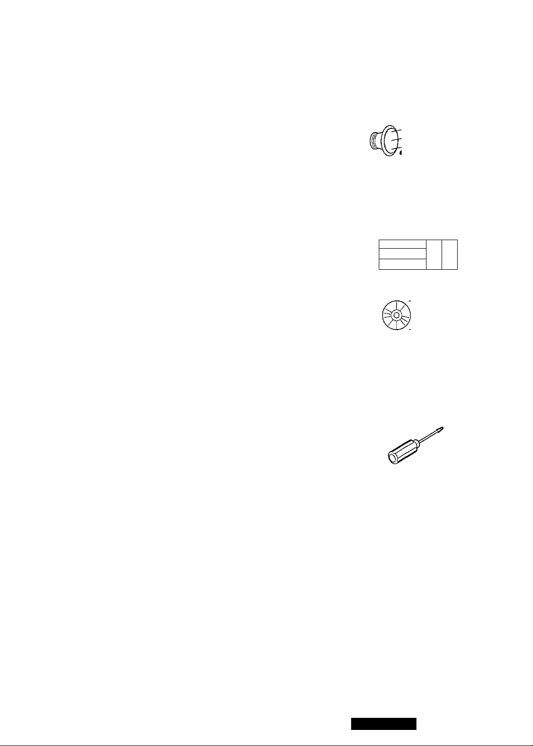
Protect the Tape Mechanism
Keep magnets, screwdrivers, or other metallic objects away from the tape mechanism and tape head to pre
vent poor performance or malfunctions.
Use Authorized Servicenters
Do not attempt to disassemble or adjust this precision equipment. Please refer to the Servicenter list includ
ed with this product for service assistance.
Find the model number and serial number on either the back or bottom of the unit. Please record them in the
space below and retain this booklet as a permanent record of your purchase to aid in identification in case
of theft.
MODEL NUMBER CQ-E15EUC SERIAL NUMBER______________
DATE PURCHASED
CQ-E15EUC
FROM
Contents
Use This Equipment Safely..........................................................................Page 2
□ Power and Sound Controls
How to adjust the volume, balance, and tone for best listening
□ Radio Basics..............................................................................
Manual and automatic tuning, band selection, preset stations
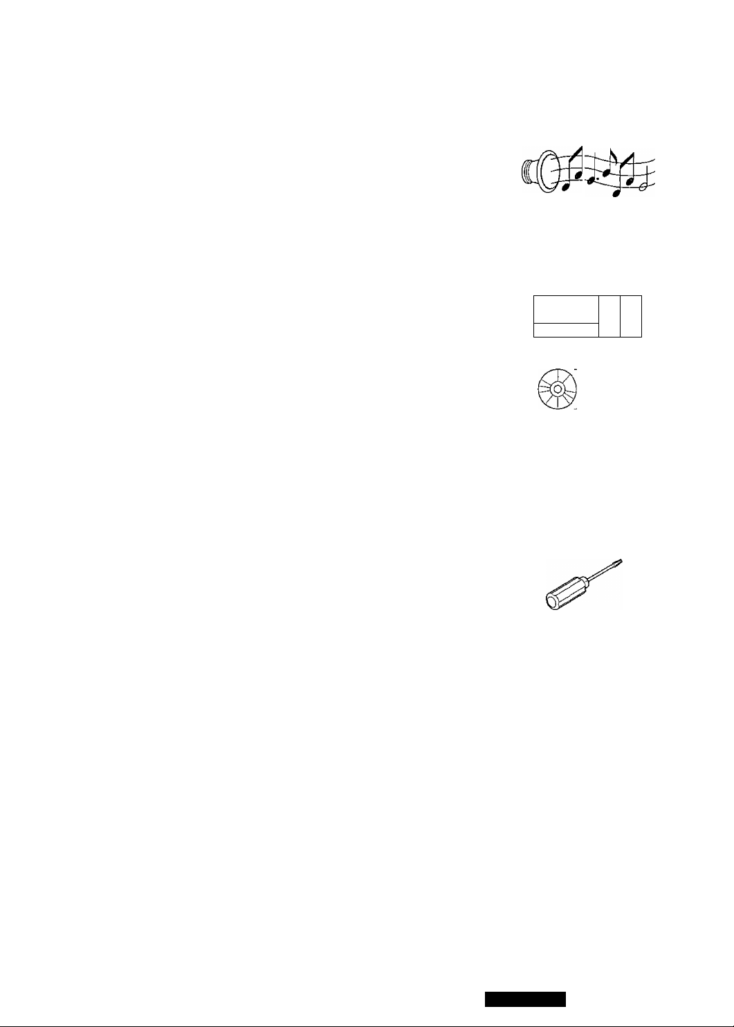
□ Cassette Tape Player Basics
How to load, wind, play, and eject a cassette tape
□ CD Changer Basics
Play, repeat, random and scan
Note :
CD changer controls are applicable to units with optional CD changer unit
(sold separately).
□ Clock Basics
Setting the time, selecting the clock display
..............................................................................
.................................................
..........................................................
.................................
.10
.12
.14
.16
toit
O
lo ol
/ \
0
O
a
nn
uu
□ Installation Guide..........................................................................................17
Step-by-step procedures, anti-theft system, electrical connections
□ Troubleshooting........................................................................................... 27 Crj\ Q
Error messages, troubleshooting tips, where to get service help o o o o o
Specifications................................................................................................... 29
CQ-E15EUC

Panasonic est heureuse de vous compter parmi les utilisateurs de ses appareils électroniques.
Nous pouvons vous assurer que cet appareil vous procurera de longues heures d’agrément. Notre réputa
tion est fondée sur une ingénierie électronique et mécanique de haute précision laquelle préside à la fabri
cation d'appareils ne comportant que des composants de choix assemblés par un personnel soucieux de la
bonne réputation acquise par la qualité de son travail. Après avoir découvert la qualité, la valeur et la fia
bilité de cet appareil, vous aussi serez fier d'être un client Panasonic.
□ Précautions à prendre
Au volant
Régler le volume à un niveau qui ne risque pas de masquer les bruits ambiants.
Lavage de la voiture
Afin de prévenir tout risque de court-circuit ou d’incendie, ne pas exposer l’équipement, y compris les hautparleurs et les cassettes, à l’eau ni à une humidité excessive.
Voiture stationnée
L’habitacle d’une voiture immobile exposée au soleil toutes vitres fermées devient rapidement très chaud.
Laisser rafraîchir l’intérieur du véhicule avant d’utiliser l’appareil.
Source d’alimentation
Cet appareil est conçu pour fonctionner sur un système d’alimentation avec batterie de 12V avec négatif à
la masse {système standard sur les voitures de construction nord-américaine).
Mécanisme de défilement
Ne pas approcher d’aimants, de tournevis ou tout autre objet métallique du mécanisme de défilement de la
bande et de la tête magnétique.
Réparation
Ne pas tenter de démonter ou d’ajuster l’appareil soi-méme. Confier toute réparation à un centre de service
agréé.
Il est recommandé de noter, dans l’espace prévu ci-dessous, les numéros de modèle et de série inscrits soit
à l’arrière soit sous le fond de l’appareil, et de conserver ce manuel comme mémorandum de l’achat afin de
permettre l’identification de l’appareil en cas de vol.
Numéro de modèle:
Date de l’achat:
EQ-E15EUC
Numéro de série;
Vendeur:
C0-E15EUC
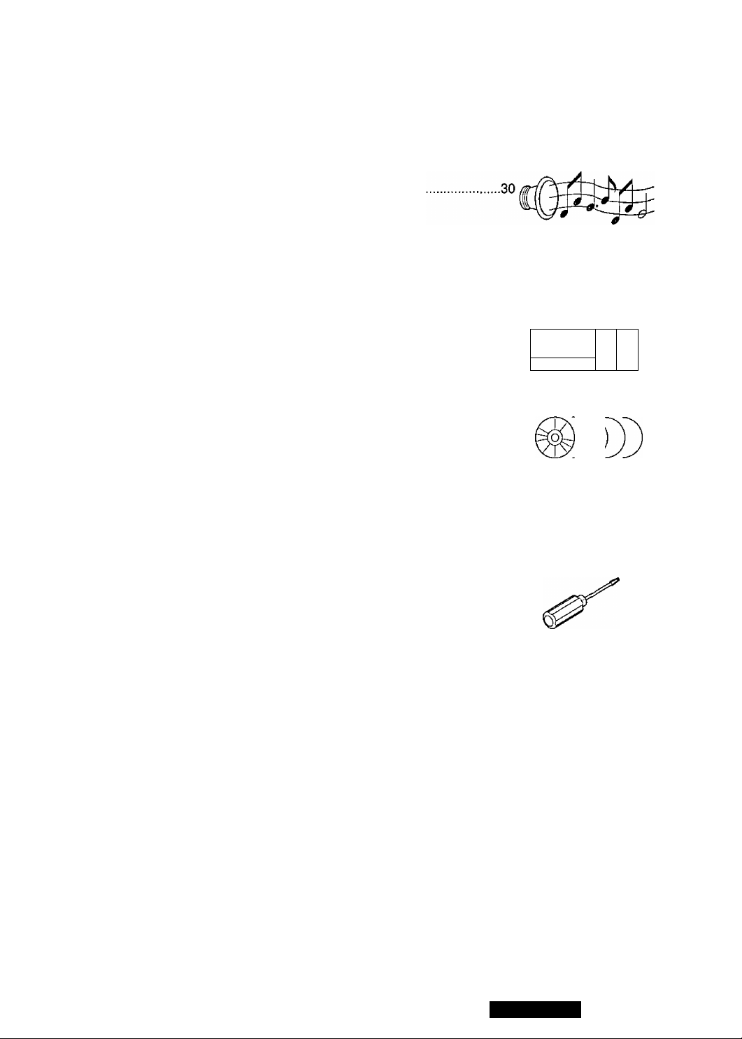
Table des matières
Précautions à prendre...........................................................................................4
□ Interrupteur et commandes de réglage de la sonorité
Réglage du volume, de l’équilibre et de la tonalité
□ Fonctionnement de la radio.........................................................................32
Syntonisation manuelle et automatique, sélection de la bande et stations en
memoire
O O
Q Fonctionnement du lecteur de cassettes............................
Chargement, lecture, rebobinage et éjection de la cassette
□ Fonctionnement du lecteur-changeur audionumérique
Lecture, lecture en reprise, lecture aléatoire et balayage
Nota;
Les commandes de changeur de disques ne s’appliquent qu’aux autoradios
auxquels un lecteur-changeur {vendu séparément) est raccordé.
□ Fonctionnement de l’horloge
Réglage de l’heure, sélection de l’affichage de l’horloge
□ Guide d’installation...................................................................
Marche à suivre, système antivol, raccordements électriques
□ En cas de difficulté.......................................................................
Messages d’erreurs, guide de dépannage, service après-vente
Données techniques..........................................................................................51
..........................................
...........................
.34
36
.38
.39
.49
lo
B:
O Q O O O
©I
\
s
nn
uu
CQ-E15EUC

Panasonic le da la bienvenida a la familia constantemente en aumento de poseedores de productos elec
trónicos. Nos esforzamos en proporcionarle tas ventajas de la ingeniería mecánica y electrónica de precisión,
de una fabricación con componentes cuidadosamente seleccionados, y de un montaje realizado por personas
orgullosas de la reputación que su trabajo ha cimentado para nuestra empresa. Estamos seguros de que este
producto le proporcionará muchas horas de distracción y, una vez comprobada la calidad, el valor y la fiabili
dad incorporados, usted también se sentirá orgulloso de pertenecer a nuestra familia.
□ Use este equipo de manera segura
Cuando esté conduciendo
Mantenga el nivel del volumen suficiente bajo para poder darse cuenta de las condiciones de tráfico de la
carretera.
Cuando esté lavando el auto
No exponga el equipo, incluso los altavoces y los discos compactos, a la agua o a la humedad excesiva.
Eso podría causar cortocircuitos, incendio u otros daños.
Cuando haya estacionado
El estacionar bajo la luz solar directa produce temperaturas muy altas dentro de su vehículo. Asegúrese de
enfriar el interior del vehículo antes de encender la unidad.
Use la fuente de alimentación apropiada
Este equipo está diseñado para funcionar con un sistema de 12 voltios, de polo negativo puesto a tierra (el
sistema normal en los autos norteamericanos).
Protección del mecanismo de la cinta
Mantenga imanes, destornilladores u otros objetos metálicos lejos del mecanismo de la cinta y de la
cabeza de la cinta para evitar rendimiento pobre o mal funcionamiento.
Use los centros de servicio autorizados
No intente desmontar o ajustar este equipo de precisión. Para solicitar ayuda relativa a los servicios de
mantenimiento, refiérase a la lista de los centros de servicio.
Busque el número del modelo y el número de serie ya sea en la parte trasera o en el fondo de la unidad.
Sírvase anotar dichos números en el espacio siguiente, y mantenga este líbrete como una anotación per
manente de su compra para ayudar en la identificación en el caso de robo.
NÚMERO DEL MODELO CQ-E1 5EUC NÚMERO DE SERIE
FECHA DE COMPRA NOMBRE DE LA TIENDA
Indice
Use este equipo de manera segura
□ Alimentación y mandos de sonido............................................................, 52
Cómo ajustar el volumen, el equilibrio y el tono para las mejores
condiciones de escucha.
□ Operación básica del radio...........................................................................54
Sintonía manual y automática, selección de la banda, estaciones
presintonizadas
□ Operación básica del tocacintas de cassette..............................................56
Cómo cargar, enrollar, tocar y expulsar una cinta cassette.
□ Conocimientos básicos cambiadiscos de CD
Reproducción, repetición, al azar y exploración.
Nota:
Los mandos del cambiadiscos de CD son aplicables a la unidad con cam
biadiscos de CD opcional (vendido separadamente).
□ Operación básica del reloj...........................................................................60
Ajuste de las horas y selección de la visualización del reloj.
.....................................................
............................................
Página 6
58
O o
O)
1©
!— A
nn
B-
uu
□ Guía de instalación......................................................................................61
Procedimientos paso a paso, sistema anti-robo, conexiones eléctricas
□ Localización de avería................................................................................ 71
Mensajes de errores, sugerencias para localización de averías,
donde obtener ayuda de servicio.
Especificaciones.........................................................................................73
o o o o o
CQ-E15EUC
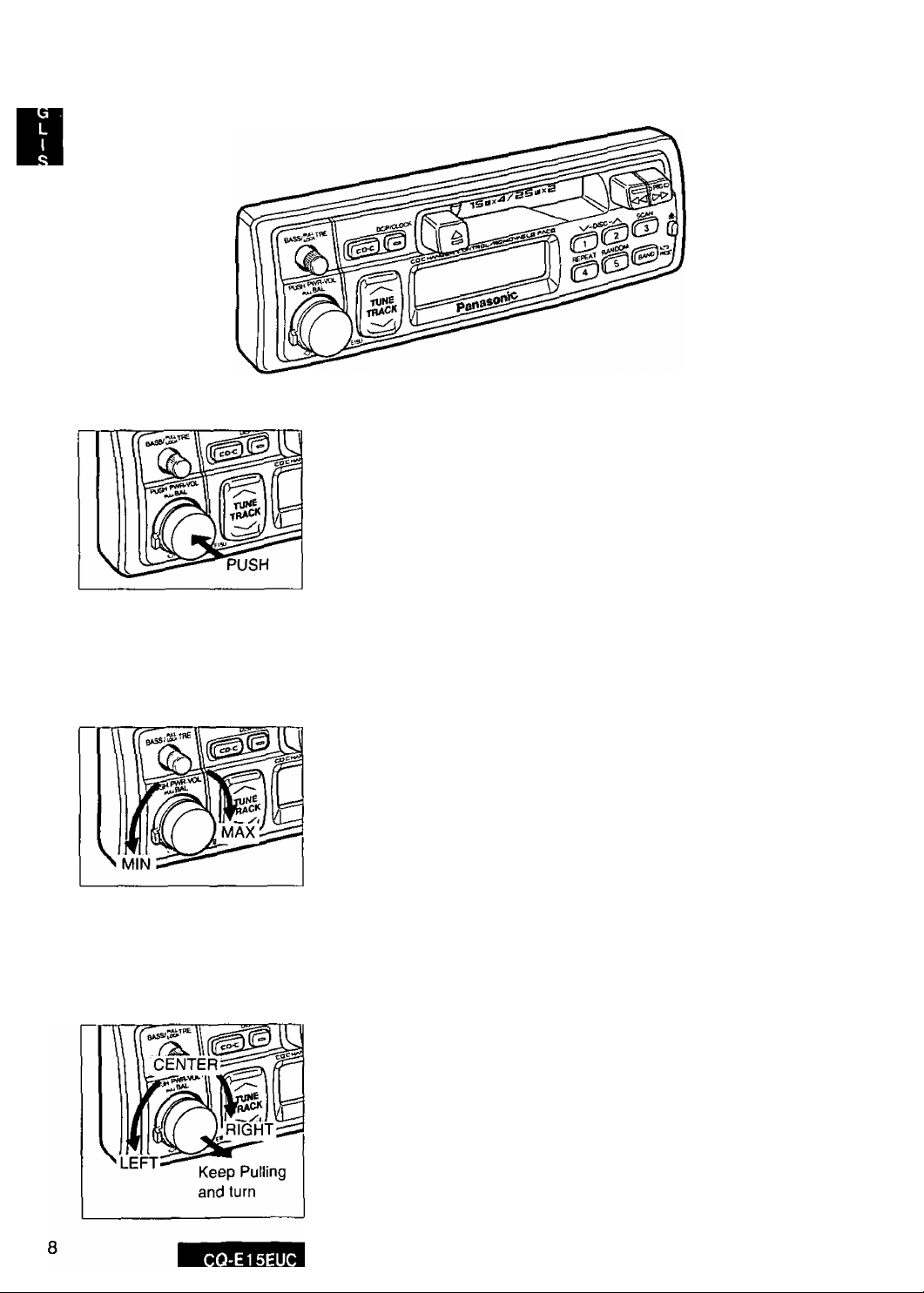
Power and Sound Controls
Power
Turn the ignition key on.
Push the knob to switch on the power.
To turn the power off, push the knob again.
Volume
Turn the knob clockwise to increase volume, and counterclockwise to de
crease volume.
Balance
Keep pulling the knob and turn it to the left or right to shift the sound vol
ume to the left or right speakers.
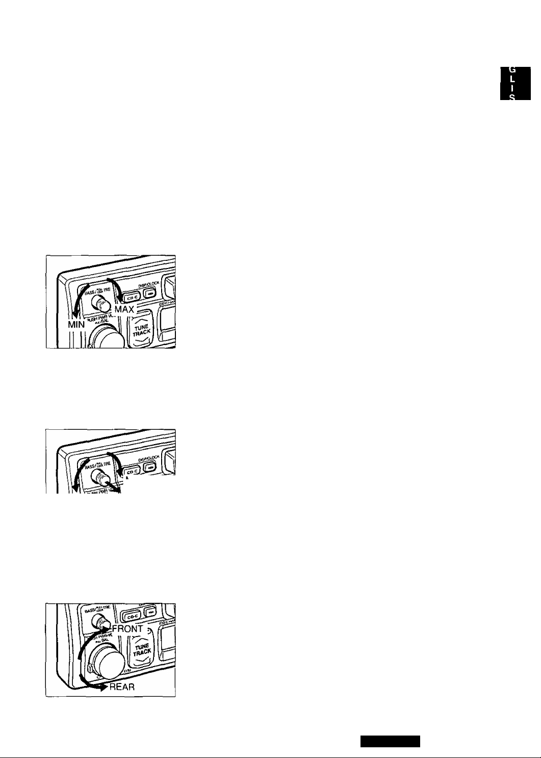
MIN Pull Lock and turn
Bass and Treble
Bass control : Turn the knob to adjust bass response.
Treble control: Pull and lock the knob and turn to adjust treble re
sponse.
After adjusting, press the knob in.
Fader
Turn to the left or right to shift the sound volunne to the rear or front
speakers.
CAUTION: Fader Control does not affect the output of the amplifier
connected to this unit’s preout cord.
CQ-E15EUC
Radio Basics
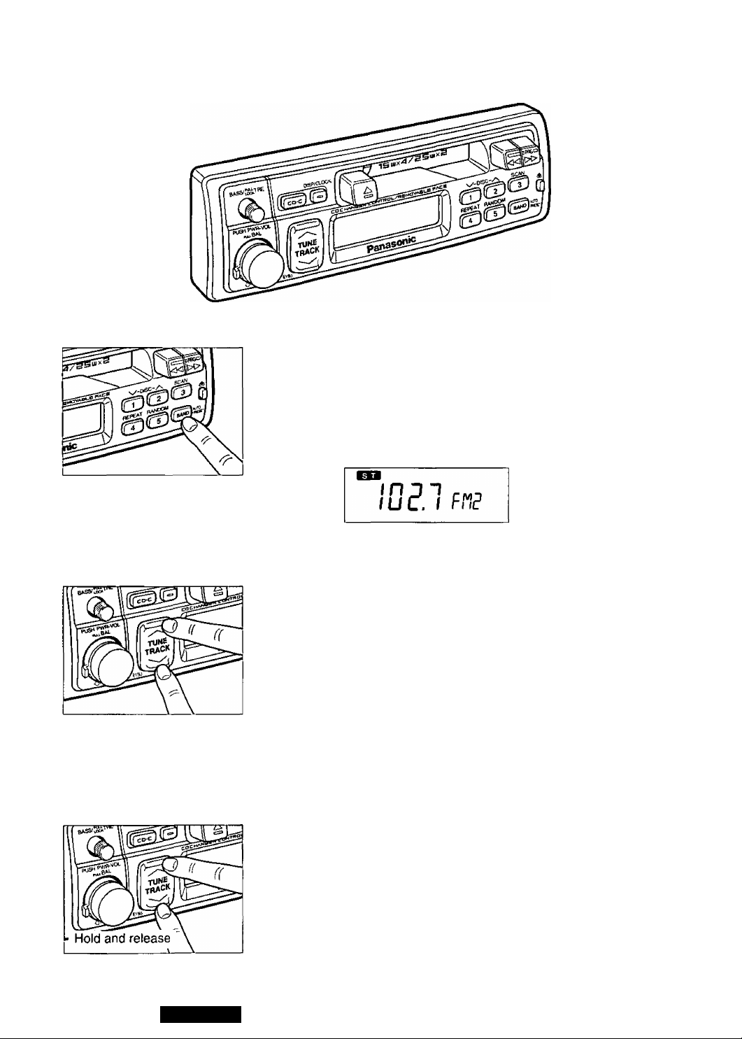
Selecting a Band
Press BAND to select the bands in the following order.
FM1
IL
“ST’ indicator lights if the station is broadcasting in stereo.
FM2 ^ FIVI3
AM
10
Manual Tuning
Press “ATUNE” or "VTUNE” to move to a higher or lower frequency.
Seek Tuning
Press and hold “ATUNE” or “ VTUNE” for more than a half second,
then release. The radio automatically stops on the next station.
CQ-E15EUC
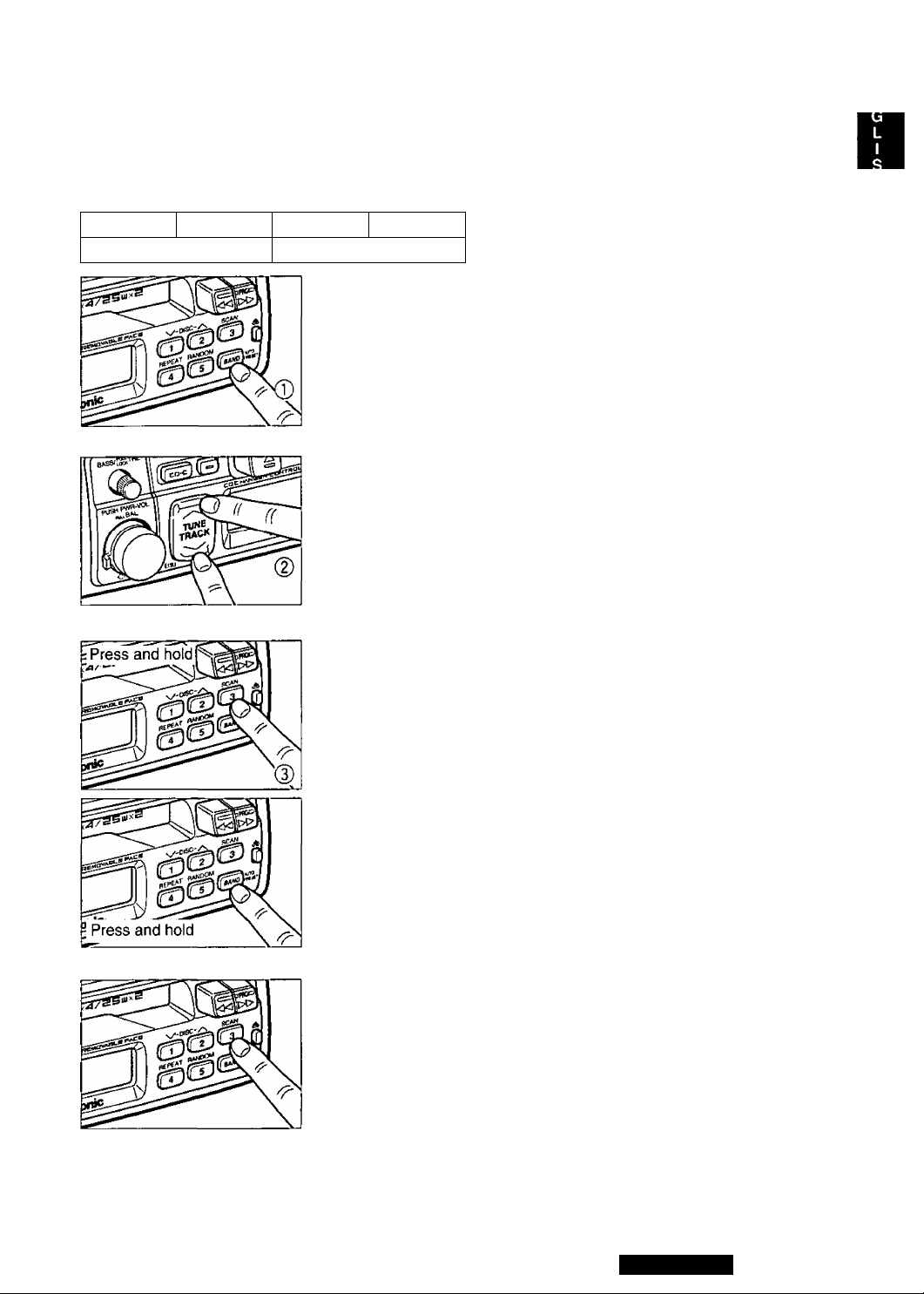
Preset Station Setting
Up to 20 stations can be preset in the station memory as follows;
FM1
5 stations 5 stations
FM2
FM3
5 stations 1 5 stations
AM
Manual Station Preset
® Press BAND to select a desired band.
CD Use manual or seek tuning to find a station that you want to program
into memory.
CD Press and hold one of the station selector buttons 1 through 5 until the
display blinks. The memory is now set for that button on the band you
have selected.
Repeat the process to set other stations for the FM1 to AM bands.
—BUTTON NUMBER
Note: You can change the memory setting by repeating the above proce
dure.
----------
Tuning in a Preset Station
Press any of the buttons 1 through 5 to tune in the station preset by the
above steps CD to CD-
Auto Station Preset
Select a band and press and hold BAND for more than 2 seconds.
• The five strongest available stations will be automatically set in memo
ry on preset buttons 1 through 5.
• Once set, the preset stations are sequentially scanned for 5 seconds.
• Press the appropriate preset button for the station you want to hear.
CAUTION; For safety reasons, do not attempt to program while driving.
CQ-E15EUC
11

I
Cassette Tape Player Basics
Loading a Cassette
Gently insert the cassette with the exposed tape facing to the right until
the mechanism captures it, and playback starts.
IflPE
PROGRAM INDICATOR
Rewind and Fast Forward
Press and engage either (REW) to rewind or ►► (FF) to fast forward the
tape.
- rpPE-
-----4-----
To stop rewind or fast forward, gently press the button that is not in use.
REWIND / resume playing from that position.
/ If you rewind the tape fully, it will play on the same program side again.
FAST FORWARD |f yQ^ fggj forward to the end, play will resume from the beginning of other
side of the tape.
^
Changing Sides
Firmly press (REW) and ►► (FF) at the same time to switch to the
program on the other side of the tape.
The display changes to indicate which program is playing.
12
CQ-E15EUC
rPPE
TOPSIDE PLAYING
7
rPPE
BOTTOM SIDE PLAYING
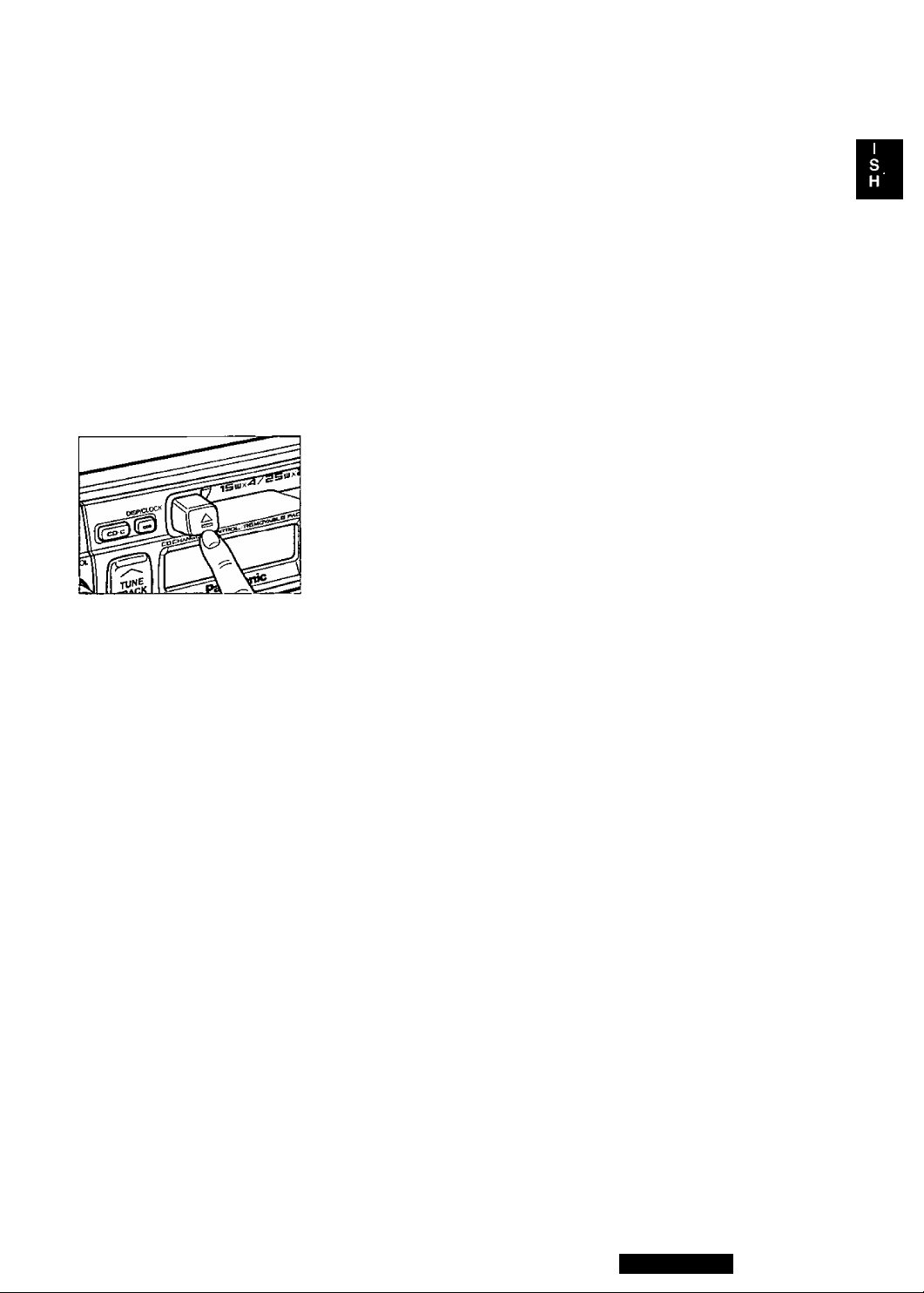
stopping and Ejecting the
Tape
Once inserted into the unit, your tape will play continuously until you
eject it.
If you press and engage ±, (EJECT), the unit clears the tape and re
turns to radio operation.
When you shut off the car engine, the tape will stop but not eject.
Note: Always remove the cassette when you are done using the cas
sette player. This will prolong the life of your tape.
CAUTION; To maintain your cassette player in top condition, avoid using tapes that are longer than 90
minutes (C-90).
CQ-E15EUC
13
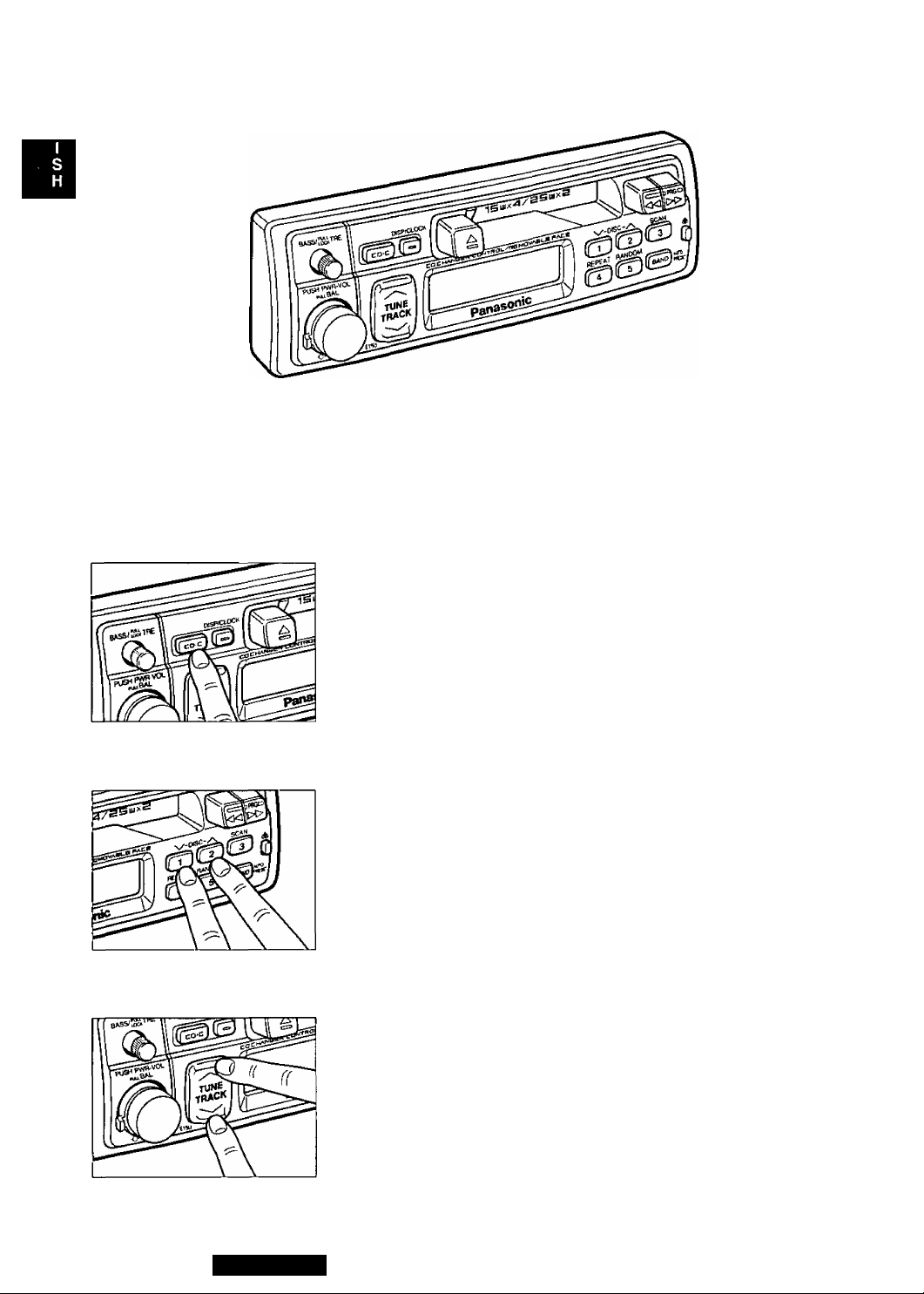
CD Changer Basics
Note: This unit’s compact disc controller is compatible with the current models CX-DP1200 and CX-DP600 and
older models CX-DP60 and CX-DP15. The general instructions of CD changer are covered here. The display
functions shown here are for CX-DP1200 and CX-DP600 only. For further details about loading CDs and hook
ing up to this unit, refer to your CD changer instruction manual.
To start the CD Player
With a disc magazine inserted in the CD Changer, press CD * C. Play
starts from first track.
aycH
l.n I
tu I
Note: The cassette, if loaded, should be removed. Otherwise, the CD
play won't start.
Selecting a Disc
Press “ V -DISC” or “DISC- A ” to select discs in descending or ascend
ing order.
C&CH
D.n (
Ju t
The disc number indicator blinks and the track number indicator stays il
luminated until the selected disc is loaded.
Selecting a Track
Press “TRACK A ” once to go to the next track. Press repeatedly to step
forward through all the tracks.
Press “ VTRACK” once to play from the beginning of the current track.
Press twice to play the previous track. Press repeatedly to step backward
through all the tracks.
14
CQ-E15EUC
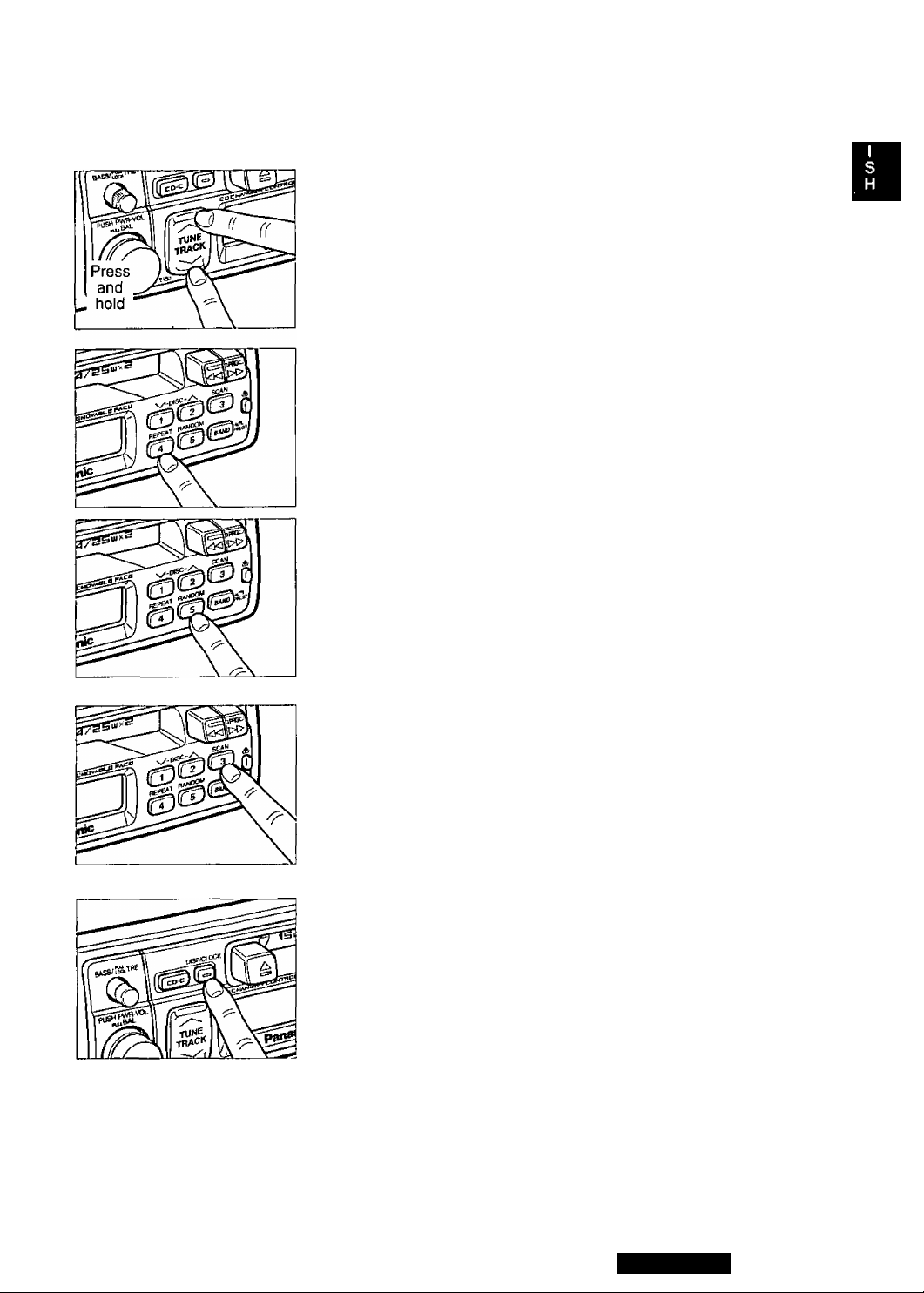
Searching a Track
Press and hold “TRACK A" or “VTRACK” for more than a half second
to activate fast fonward or reverse through a track. Release “TRACK A”
or "V TRACK” to resume the normal CD play from that position.
Repeating a Track
Press REPEAT to repeat the current selection. “REPEAT’ indicator
lights. The current selection continues to repeat until you press RE
PEAT again.
REPEAT
Random Selection
Press RANDOM. “RANDOM" indicator lights. A random selection of
music is played from all available CDs. To turn off, press RANDOM
again.
RANDOM
Scanning Tracks
Press SCAN. The display blinks and the first 10 seconds of each track
on the discs play in sequence.
To stop scanning and continue with the current track, press SCAN
again.
Changing the Display
Press DISP to switch the display in sequence as follows.
Note: To change to the Radio mode, press BAND.
Disc/Track Number
i
Track Play Time
CQ-E15EUC
15
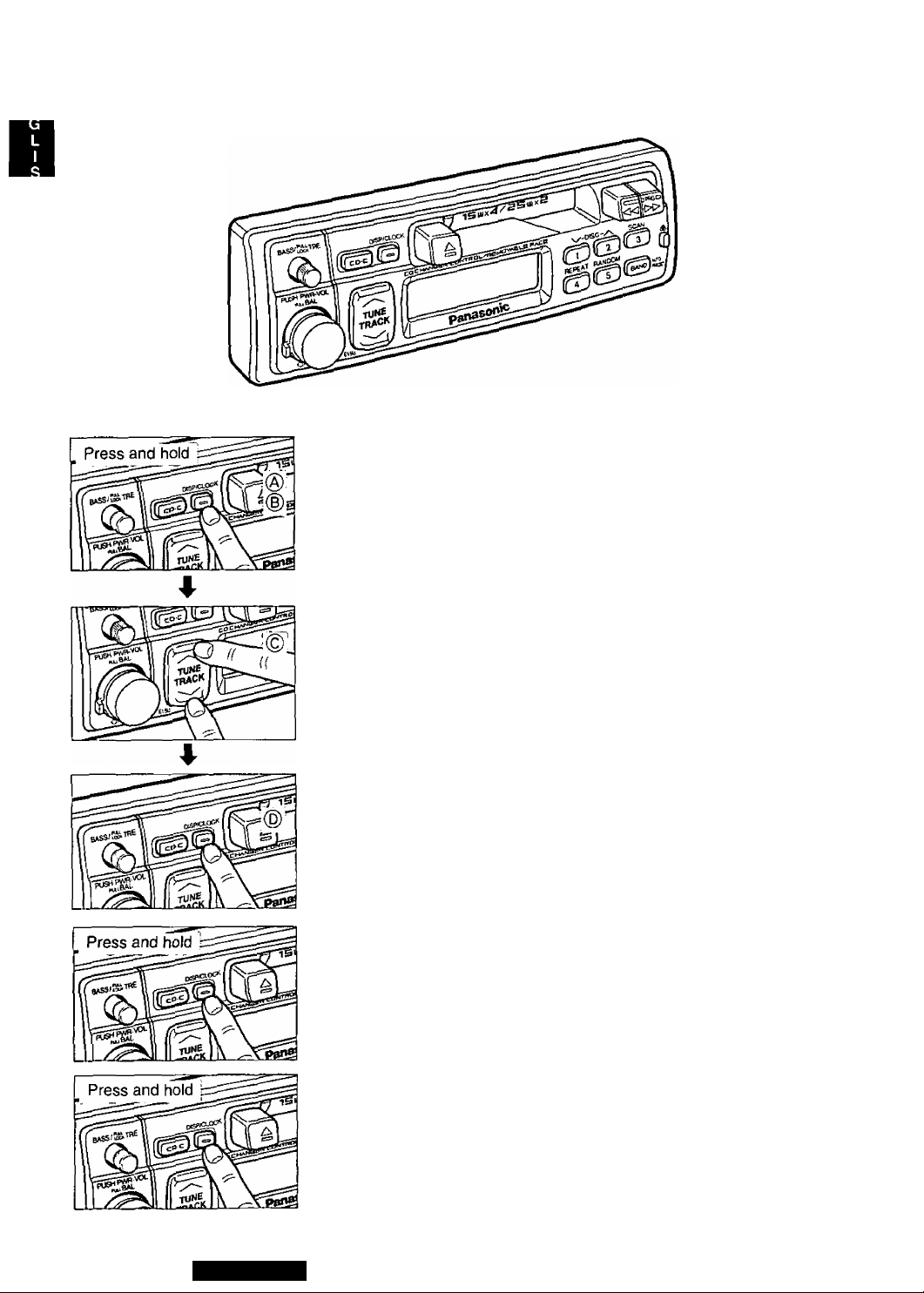
Clock Basics (The clock system is 12-hours.)
Initial Time Setting
® Press and hold DISP/CLOCK for more than 2 seconds. “ AdJ” is dis
played.
(B) Press and hold DISP/CLOCK again for more than 2 seconds. “ AdJ”
blinks indicating the time setting mode is activated.
^ +
© To set hours, press “ A TUNE”.
n-nn
To set minutes, press 'TUNE V”.
4-
- B: IS -
——I—^
Hold “A” or “V” to change numbers rapidly.
® When you have set the time, press DISP/CLOCK.
Resetting the Time
When you want to reset the time, press and hold DISP for more than 2
seconds for 2 times to activate the time setting mode (for 1 time when
the time is displayed). Then, repeat step © and ®.
Selecting the Clock Display
Press and hold DISP/CLOCK for more than 2 seconds to switch the dis
play between each listening mode (Radio, Tape and CD) and the clock.
16
CQ-E15EUC
□ Overview
This equipment should be installed by a profession
al. However, if you plan to install this unit yourself,
your first step is to decide where to install it. The in
structions in these pages will guide you through the
remaining steps: (Please refer to “WARNING" state
ment above).
• Identify and label the vehicle wires
• Connect the vehicle wires to the wires of the
power connector
• Install the unit in the dash
® Check the operation of the unit
If you do encounter problems, please consult your
nearest professional installer.
□ Installation Hardware
No. Item Diagram
Mounting Collar
©
Plain Washer (5 mm(t))
©
Spring Washer (5 mm0)
©
Hex. Nut (5 mm({i)
©
Rear Support Strap
(D
©
Qty
1
2
2
2
1
CAUTION: This unit will operate with a 12 volt DC
negative ground auto battery system only. Do not
attempt to use it in any other system. Doing so
could cause serious damage.
Before you begin installation, look for the following
items included in the packing with your unit.
o Warranty Card
• MSC (in Canada; Panasonic) Servicenter Di
rectory
the unit needs servicing
« Installation Hardware
installation
.......
Fill this out promptly
.......
Keep for future reference in case
.........
Needed for in-dash
Hex. Bolt
®
(5 mm0 X 25 mm)
Toothed Lock Washer
©
(5 mmcf))
Mounting Bolt (5 mmifi)
Power Connector
®
Unit Case
CQ-E15EUC
%
1
1
1
1
1
17
Installation Guide continued
Cut the connector plug off (leaving the leads as long
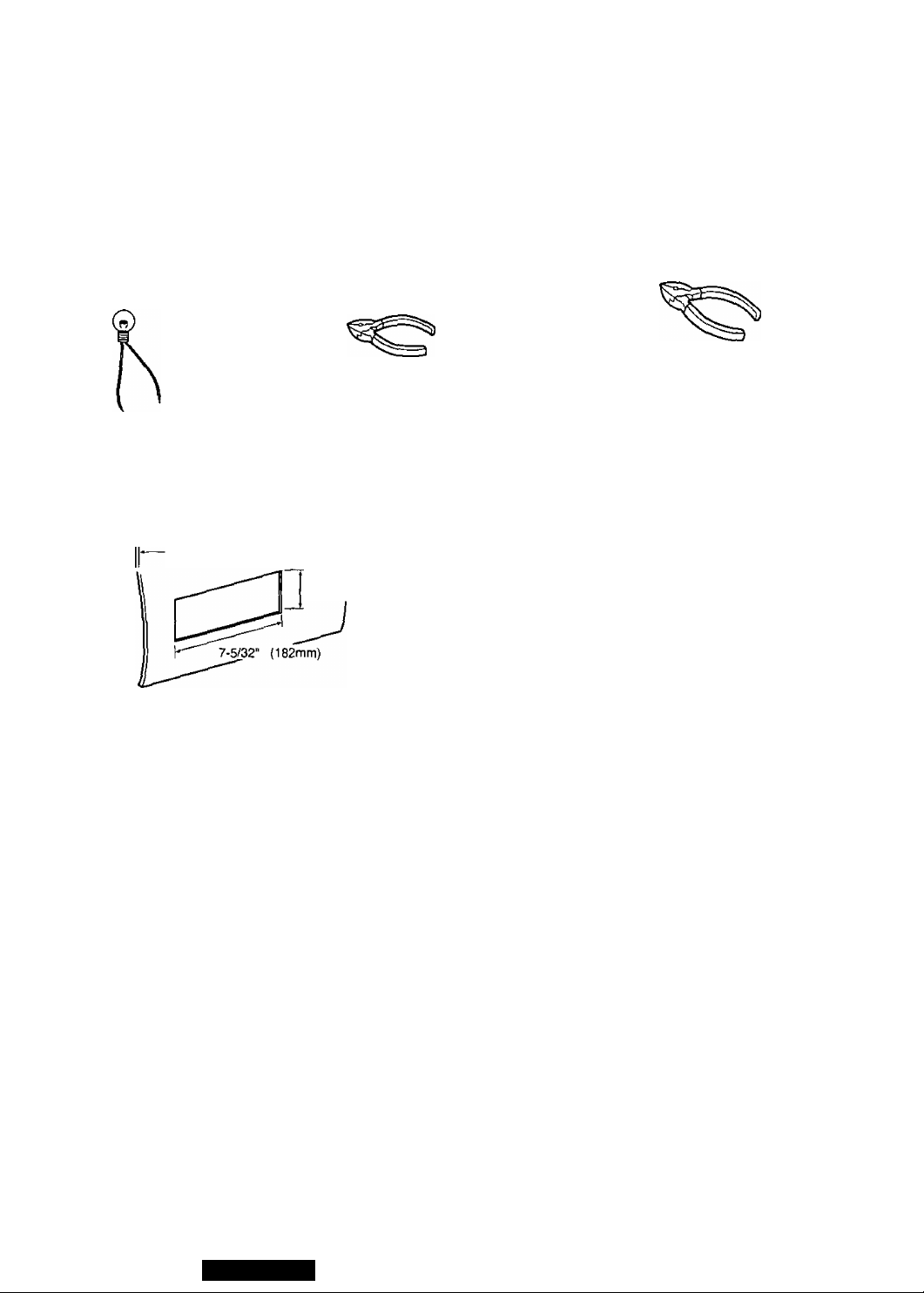
□ Required Tools
You’ll need a screwdriver, a 1.5 volt AA battery, and
the following;
as possible) so that you can work with individual
leads.
12 V DC
TEST BULB
ELECTRICAL
TAPE
SIDE-CUT
PLIERS
□ Dashboard Specifications
THICKNESS
MIN. 3/16" (4.75 mm)
MAX, 7/32" (5.56 mm)
2-3/32' (53 mm)
□ Identify All Leads
The first step in installation is to identify all the vehi
cle wires you’ll use when hooking up your sound
system.
As you identify each wire, we suggest that you label
it using masking tape and a permanent marker. This
will help avoid confusion when making connections
later.
Note: Do not connect the power connector to the
stereo unit until you have made all connections. If
there are no plastic caps on the stereo hooking
wires, insulate all exposed leads with electrical tape
until you are ready to use them. Identify the leads in
the following order.
Turn the ignition on to the accessory position, and
ground one lead of the test bulb to the chassis.
Touch the other lead of the test bulb to each of the
exposed wires from the cut radio connector plug.
Touch one wire at a time until you find the outlet that
causes the test bulb to light.
Now turn the ignition off and then on. If the bulb
also turns off and on, that outlet is the vehicle
power lead.
If your vehicle is not wired for an audio unit:
Go to the fuse block and find the fuse port for radio
(RADIO), accessory (ACC), or ignition (IGN).
Battery Lead
If your stereo unit has a yellow lead, you will need
to locate the car's battery lead. Otherwise you may
ignore this procedure. (The yellow battery lead pro
vides continuous power to maintain a clock, memo
ry storage, or other function.)
If your vehicle has a radio or is pre-wired for one;
With the ignition and headlights off, identify the car
battery lead by grounding one lead of the test bulb
to the chassis and checking the remaining exposed
wires from the cut radio connector plug.
If your vehicle is not wired for an audio unit;
Go to the fuse block and find the fuse port for the
battery, usually marked BAT.
Power Lead
If your vehicle has a radio or is pre-wired for one :
18
CÛ-E15EUC
Speakers
Identify the car speaker leads. There will be two
leads for each speaker, usually color coded.
A handy way to identify the speaker leads and the
speaker they connect with is to test the leads using
a 1.5 volt AA battery as follows.
Hold one lead against one pole of the battery and
stroke the other lead across the other pole. You will
hear a scraping sound in a speaker if you are hold
ing a speaker lead.
If not, keep testing different lead combinations until
you have located all the speaker leads. When you
label them, include the speaker location for each.
Speakers
Connect the speaker wires. See the wiring diagram
below for the proper hookups. Follow the diagram
carefully to avoid damaging the speakers and the
stereo unit.
The speaker used must be able to handle more
than 25 watts of audio power. If using an optional
audio power, the speakers should be able to handle
the maximum amplifier output power. Speakers
with low input ratings can be damaged.
Antenna Motor
If your vehicle is equipped with an automatic power
antenna, identify the vehicle motor antenna lead by
connecting one bulb tester lead to the vehicle bat
tery lead and touching the remaining exposed wires
from the cut radio connector plug one at a time. You
will hear the antenna motor activate when you touch
the correct wire.
Antenna
The antenna lead is a thick, black wire with a metal
plug at the end.
□ Connect All Leads
Now that you have identified all the wires in the ve
hicle, you're ready to begin connecting them to the
stereo unit wires. The connection diagram on Page
26 shows the proper connections and color coding
of the leads.
We strongly recommend that you test the unit be
fore making a final installation.
You can set the unit on the floor and make tempo
rary connections to test the unit. Use electrical tape
to cover all exposed wires.
Speaker impedance should measure 4 - 8 ohms,
which is typically marked on most speakers, Lower
or higher impedance speakers will affect output and
can cause both speaker and stereo unit damage.
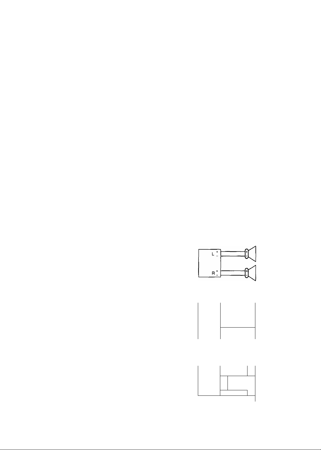
CAUTION ; Never ground the speaker cords. For
example, do not use a chassis ground system or a
three-wire speaker common system. Each speaker
must be connected separately using parallel insulat
ed wires. If in doubt about how your car's speakers
are wired, please consult with your nearest profes
sional installer.
CORRECT
No Common Ground
INCORRECT
Common Chassis Ground
L :
IMPORTANT ; Connect the red power lead last,
after you have made and insulated all other connec
tions.
Ground
Connect the black ground lead of the power con
nector to the metal vehicle chassis.
R *
INCORRECT
Speaker Common
(common earth lead)
------------
L ^
R *
:
r1
rrl
19

Installation Guide
Motor Antenna
Connect the vehicle motor antenna lead to the blue
motor antenna relay control lead.
Battery
Connect the yellow battery lead to the correct radio
wire or to the battery fuse port on the fuse block.
continued
□ Final Installation
Lead Connections
Connect all wires, making sure that each connec
tion is insulated and secure. Bundle all loose wires
and fasten them with tape so they won't fall down
later. Now insert the stereo unit into the mounting
collar.
Antenna
Connect the antenna by plugging the antenna lead
into the antenna receptacle.
Equipment
Connect any optional equipment such as amplifier,
according to the instructions furnished with the
equipment. Keep about 12 inches (30 cm) of dis
tance between the speaker cords/amplifier unit and
the antenna/antenna extension cord. Read the op
erating and installation instructions for any equip
ment you will connect to this unit.
Power
Connect the red power lead to the correct vehicle
radio wire or to the appropriate fuse port on the fuse
block.
If the stereo unit functions properly with all these
connections made, disconnect the wires and pro
ceed to the final installation.
Congratulations! After making a few final checks,
you’re ready to enjoy your new auto stereo system.
□ Final Checks
1. Make sure that all wires are properly connect
ed and insulated.
2. Make sure that the stereo unit is securely held
in the mounting collar.
3. Turn on the ignition to check the unit for prop
er operation.
If you have difficulties, consult your nearest autho
rized professional installer for assistance.
20
CQ-E15EUC
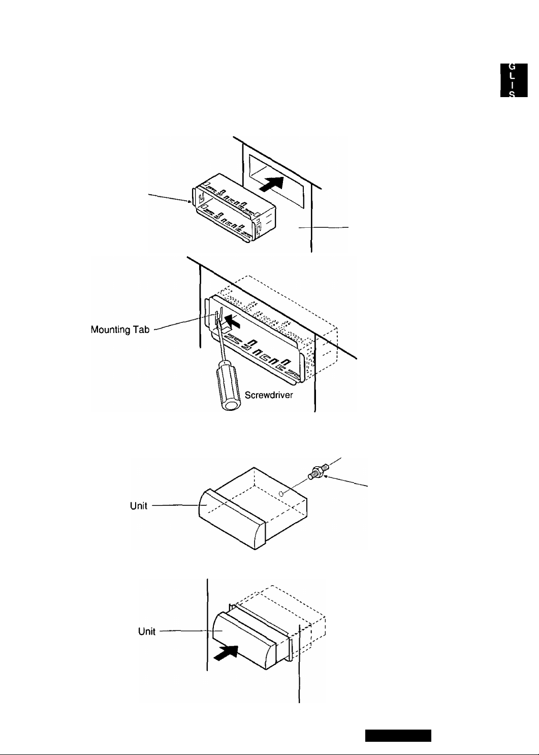
□ Installation Procedures
1. Secure the Mounting Collar ®.
Insert Mounting Collar© into the car’s dashboard, and bend mounting tabs out with a screwdriver.
(D Mounting Collar
Dashboard
2. Secure the rear of the unit.
a) Check the electrical connection by referring to this operating instructions.
b) Connect the Mounting Bolt CD, using a suitable wrench.
(8) Mounting Bolt
c) Insert the unit into Mounting Collar ® and push it in until “click” is heard.
d) Secure the rear of the unit to the car by either of the two recommended methods on the next page.
CQ-E15EUC
21
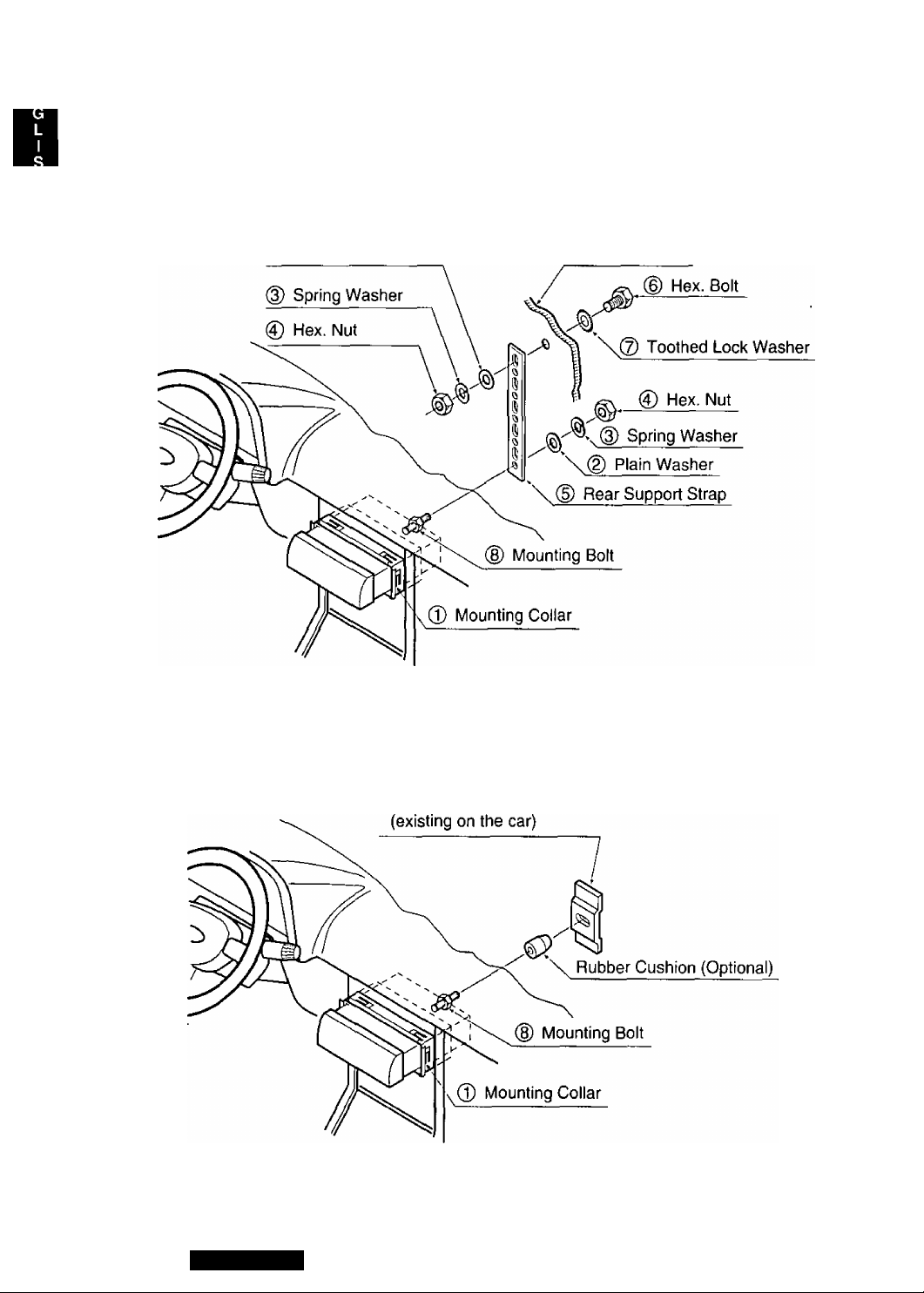
Installation Guide continued
Using the Rear Support Strap (D
Affix one end of the Rear Support Strap (D to the rear of the unit, and the other end to the Fire Walt of Car,
or some other metallic area.
Ф Plain Washer
Using the Rubber Cushion (Optional)
(If there is an existing Rear Support Bracket on the Fire Wall of Car.)
Cover Mounting Bolt (8) on the rear of the unit with Rubber Cushion (Optional), and mount it into the exist
ing Rear Support Bracket.
Fire Wall of Car
22
Rear Support Bracket
CQ-E15EUC
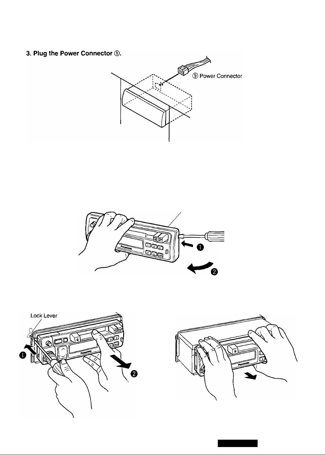
4. After installation reconnect the negative (—) battery terminal.
To Remove the Unit
a) Remove the trim plate with a screwdriver as shown in the figure.
Trim Plate
b) Puil out the unit while pushing the lock lever using a screwdriver.
c) Remove the unit pulling with both hands.
^ Screwdriver
CQ-E15EUC
23
 Loading...