

Panasonic CFS-B5LMK2 Service Manual
CFS-B5LMK2
SERVICE MANUAL
Ver 1.0 1999. 05
SPECIFICATIONS
East European Model
Model Name Using Similar Mechanism NEW
Tape T r ansport Mechanism T ype MF-B5MK2-117
Frequency range
FM: 65.0 - 108 MHz
MW: 531 - 1,602 kHz
LW: 153 - 279 kHz
SW: 5.95 - 18 MHz
Aerials
FM/SW: T elescopic antenna
MW/LW: Built-in ferrite bar
Recording system
4-track, 2-channel stereo
Frequency response
70 - 10,000 Hz
Speakers
Full range: 10 cm (4 inches) dia.,
2.8 ohms cone type × 2
Output
Headphones jack (stereo minijack),
for 16 - 68 ohms impedance headphones
Maximum power output
2.5 W + 2.5 W
Battery life
FM recording
Sony R20P: approx. 16 hours
Sony LR20 alkaline: approx. 36 hours
Playback
Sony R20P: approx. 8 hours
Sony LR20 alkaline: approx. 21 hours
Power requirements
230 V AC, 50 Hz
9 V DC, six R20 (size D) batteries
Power consumption
AC 14 W
Dimensions
Approx. 500 × 155 × 164 mm (w/h/d)
3/4 × 6 1/8 × 6 1/2 inches) incl. projecting parts
(19
and controls, not incl. handle
Mass
Approx. 2.7 kg (5 lb. 15 oz.) not incl. batteries
Supplied accessory
Mains lead (1)
Design and specifications are subject to change without
notice.
MICROFILM
RADIO CASSETTE-CORDER
– 1 –

TABLE OF CONTENTS
1. GENERAL
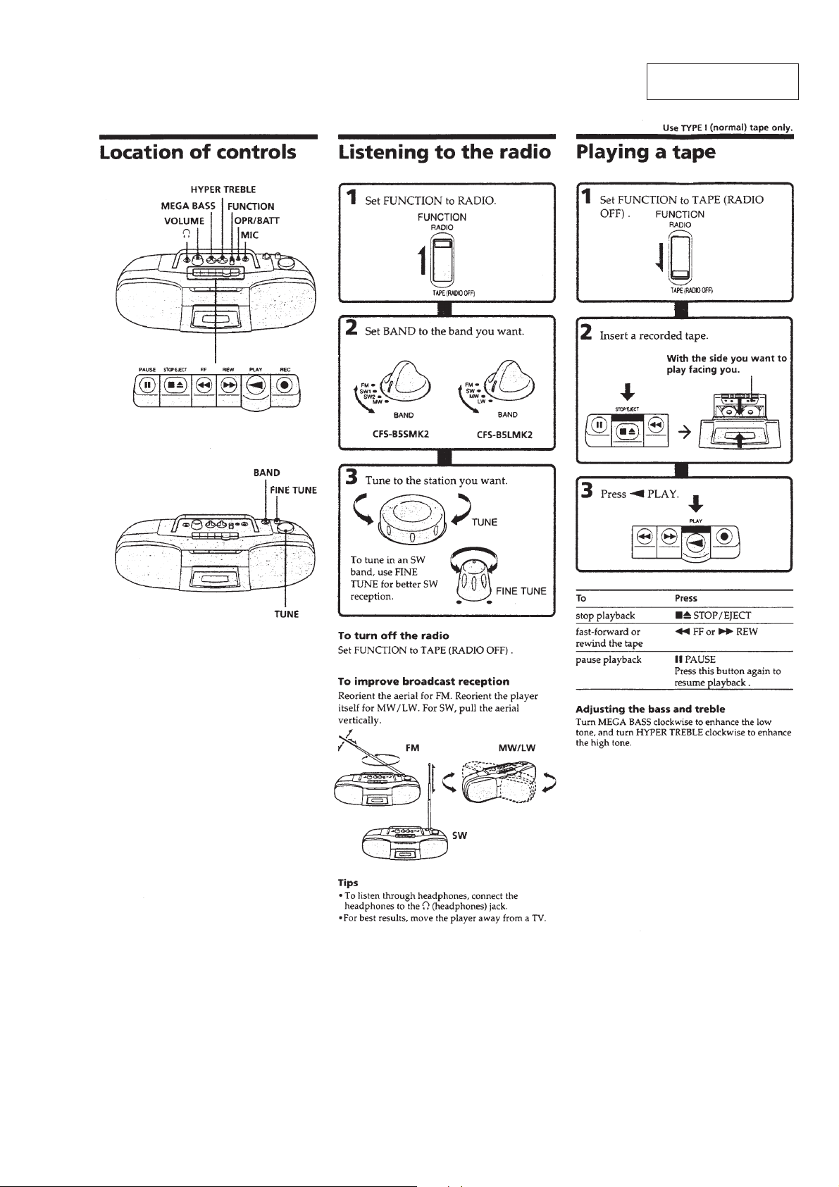
Location of Controls................................................................ 3
Listening to the Radio ............................................................. 3
Playing a Tape ......................................................................... 3
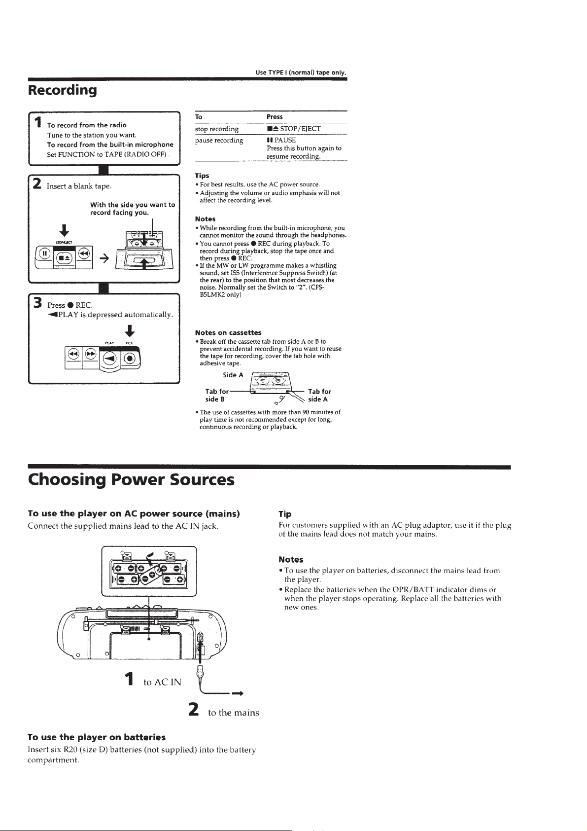
Recording ................................................................................ 4
Choosing Power Sources ......................................................... 4
2. DISASSEMBLY
2-1. Cabinet (Front) Sub Assy (B)..............................................5
2-2. Chassis (Tune)..................................................................... 5
2-3. Tape Mechanism Block ....................................................... 6
2-4. Tuner, AC, Second Board .................................................... 6
2-5. Audio, Microphone, ISS Board........................................... 7
2-6. Dial Pointer Setting ............................................................. 7
3. MECHANICAL ADJUSTMENTS................................. 8
4. ELECTRICAL ADJUSTMENTS
4-1. Tape Recorder Section ........................................................ 8
4-2. Tuner Section ...................................................................... 9
5. DIAGRAMS
5-1. Block Diagram .................................................................. 11
5-2. Circuit Boards Location .................................................... 13
5-3. Printed Wiring Board –Tuner Section– ............................. 14
5-4. Schematic Diagram –Tuner Section–................................15
5-5. Printed Wiring Boards –Main Section– ............................ 17
5-6. Schematic Diagram –Main Section–................................. 19
6. EXPLODED VIEWS
6-1. Cabinet (Front) Section ..................................................... 21
6-2. Cabinet (Rear) Section ...................................................... 22
6-3. Tape Mechanism Deck Section (1) ................................... 23
6-4. Tape Mechanism Deck Section (2) ................................... 24
7. ELECTRICAL PARTS LIST......................................... 25
SAFETY-RELATED COMPONENT WARNING!!
COMPONENTS IDENTIFIED BY MARK ! OR DOTTED LINE
WITH MARK ! ON THE SCHEMATIC DIAGRAMS AND IN
THE PARTS LIST ARE CRITICAL TO SAFE OPERATION.
REPLACE THESE COMPONENTS WITH SONY PARTS WHOSE
P ART NUMBERS APPEAR AS SHOWN IN THIS MANU AL OR
IN SUPPLEMENTS PUBLISHED BY SONY.
– 2 –
SECTION 1
GENERAL
This section is extracted
from instruction manual.
– 3 –
– 4 –
SECTION 2
DISASSEMBLY
• The equipment can be removed using the following procedure.
Set / Cabinet (front) sub assy (B) / Chassis (TUNE) / Tape mechanism block /
Tuner, AC, Second board / Audio, Microphone, ISS board
Note : Follow the disassembly procedure in the numerical order given.
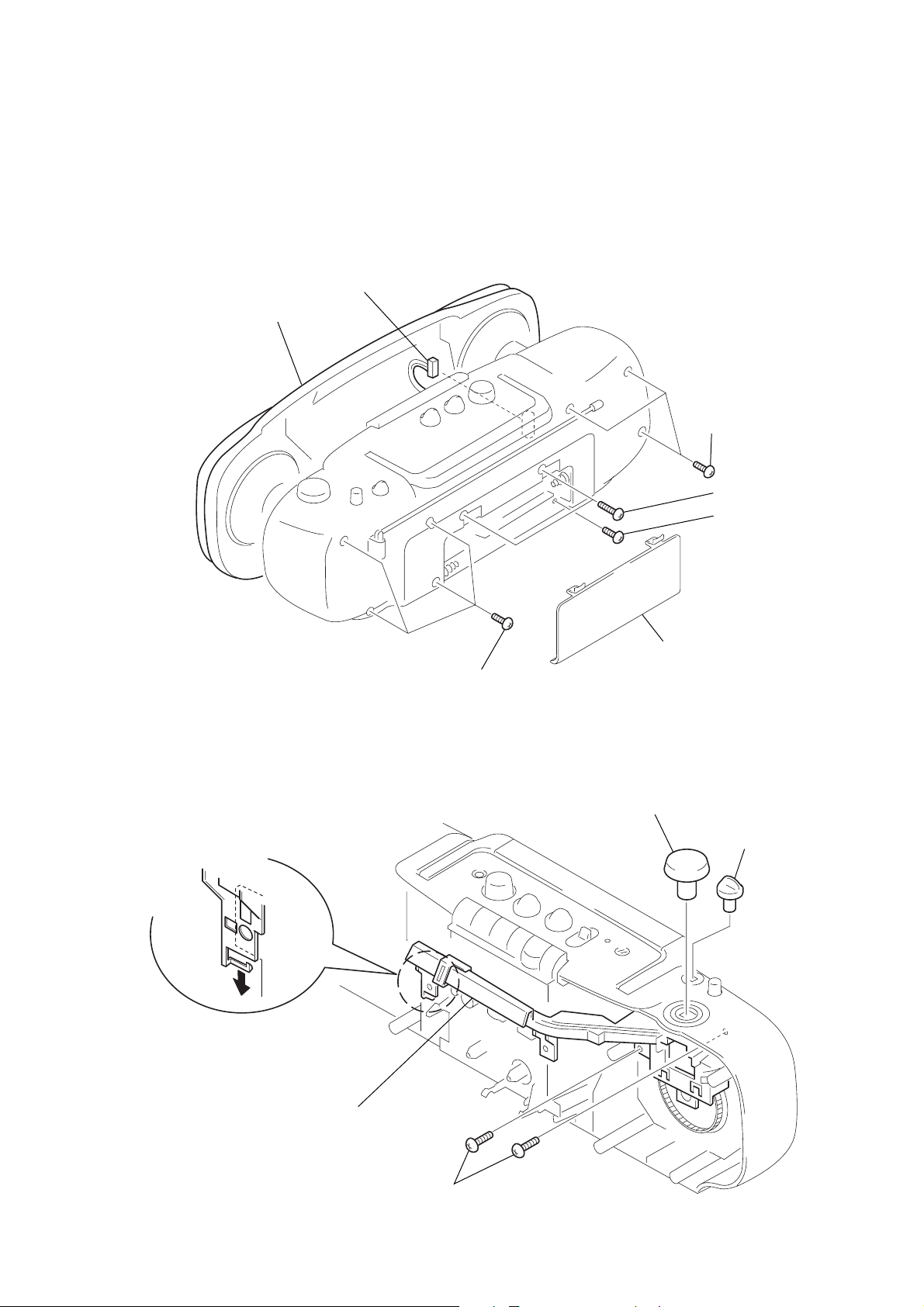
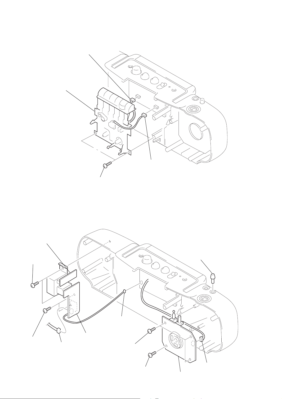
2-1. CABINET (FRONT) SUB ASSY (B)
6
CN912
7
cabinet (front)
sub assy (B)
4
BVTP 3x12
3
BVTP 3x16
2
BVTP 3x12
2-2. CHASSIS (TUNE)
5
BVTP 3x12
1
lid, battery case
1
knob (TUNE)
2
knob (FUNCTION)
4
chassis (TUNE)
3
BVTP 3x10
– 5 –
2-3. TAPE MECHANISM BLOCK
3
4
tape mechanism block
CN601
2
CN301
2-4. TUNER, AC, SECOND BOARD
!¡
SECOND board
8
BVTP 3x10
1
BVTP 3x10
1
knob (FINE)
9
BVTP 3x10
7
CN901
0
AC board
6
CN911
3
– 6 –
BVTP 3x10
2
BVTP 3x10
5
TUNER board
4
CN1
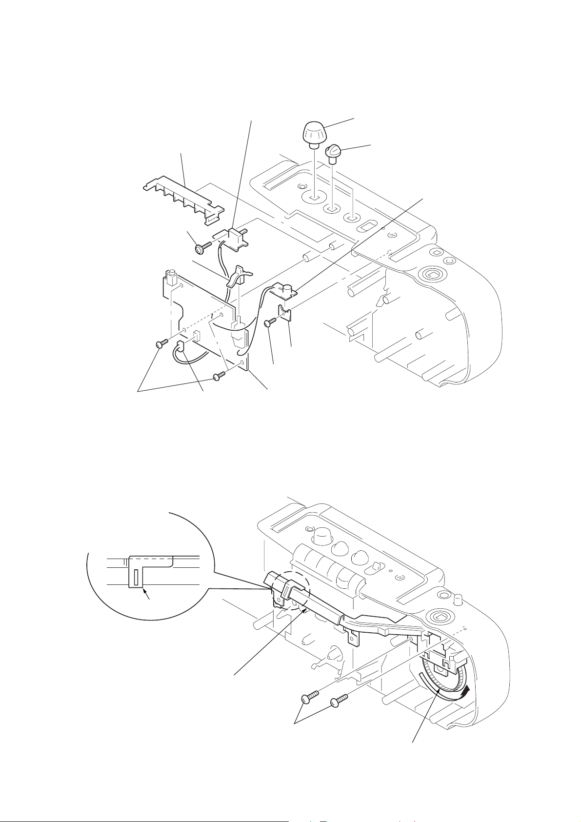
2-5. AUDIO, MICROPHONE, ISS BOARD
3
chassis (MD)
!¡
tapping screw (3x12)
9
lever (FUNCTION)
!™
lSS board
5
SUPPORT board
1
knob (VOL)
2
knob (TONE)
6
MICROPHONE board
7
BVTP 3x10
2-6. DIAL POINTER SETTING
2
Set the pointer to the
center of scratched lines.
pointer
0
CN341
4
BVTP 3x10
8
AUDIO board
3
Set the chassis (TUNE).
4
BVTP 3x10
– 7 –
1
Turn gear (VC) counterclockwise
to the end.
 Loading...