

Page 1
Iris Camera
REJECT ACCEPT
BM-ET300
Setup Manual
Model No. BM-ET300
Before attempting to connect or operate this product,
please read these instructions carefully and save this manual for future use.
Page 2

CONTENTS
PREFACE . . . . . . . . . . . . . . . . . . . . . . . . . . . . . . . . . . . . . . . . . . . . . . . . . . . . . . . . . . . . . . . . . . . . . . . . . . . . . . . . . . . . . . . 3
FEATURES . . . . . . . . . . . . . . . . . . . . . . . . . . . . . . . . . . . . . . . . . . . . . . . . . . . . . . . . . . . . . . . . . . . . . . . . . . . . . . . . . . . . . . 4
NOTIFICATION ABOUT THIS DOCUMENT . . . . . . . . . . . . . . . . . . . . . . . . . . . . . . . . . . . . . . . . . . . . . . . . . . . . . . . . . . . . . 5
TRADEMARKS . . . . . . . . . . . . . . . . . . . . . . . . . . . . . . . . . . . . . . . . . . . . . . . . . . . . . . . . . . . . . . . . . . . . . . . . . . . . . . . . . . . 5
LIMITATION OF LIABILITY . . . . . . . . . . . . . . . . . . . . . . . . . . . . . . . . . . . . . . . . . . . . . . . . . . . . . . . . . . . . . . . . . . . . . . . . . . 5
DOCUMENT CONVENTION . . . . . . . . . . . . . . . . . . . . . . . . . . . . . . . . . . . . . . . . . . . . . . . . . . . . . . . . . . . . . . . . . . . . . . . . . 6
PRECAUTIONS . . . . . . . . . . . . . . . . . . . . . . . . . . . . . . . . . . . . . . . . . . . . . . . . . . . . . . . . . . . . . . . . . . . . . . . . . . . . . . . . . . . 7
MAJOR OPERATING CONTROLS AND THEIR FUNCTIONS . . . . . . . . . . . . . . . . . . . . . . . . . . . . . . . . . . . . . . . . . . . . . . . . 9
SETUP PROCEDURE . . . . . . . . . . . . . . . . . . . . . . . . . . . . . . . . . . . . . . . . . . . . . . . . . . . . . . . . . . . . . . . . . . . . . . . . . . . . . . 11
■ Installation of the Setup Software and Setup Procedure . . . . . . . . . . . . . . . . . . . . . . . . . . . . . . . . . . . . . . . . . . . . . . . 11
■ Setting Parameters of the Setup Software . . . . . . . . . . . . . . . . . . . . . . . . . . . . . . . . . . . . . . . . . . . . . . . . . . . . . . . . . . . 13
2
Page 3
PREFACE
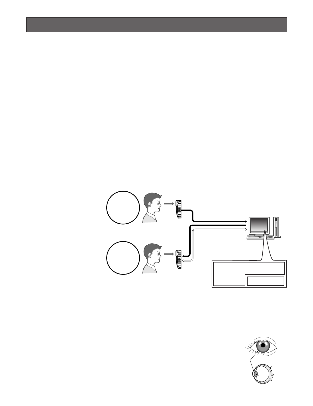
Iris Camera BM-ET300 is used in an access control system. The iris camera, which captures a user's iris image, is available for
following uses.
• As an enrollment camera for iris image capturing and iris server enrollment
To activate iris recognition, it is necessary to capture the iris images of a user and enroll the iris data in the iris server.
An iris camera generates iris data from iris images captured, and transfers the data to the iris server in the LAN (Local Area
Network). The iris data is enrolled in the iris database of the iris server. Up to 5 000 users can enroll their iris data. *
*1For iris data enrollment, you need to install the optional Administration Software BM-ES300E and User License Software
BM-EU30000E Series onto a PC. The PC needs to have Microsoft® Windows® operating system installed.
The total number of users that can be enrolled differs depending on the total license numbers of the User License Software
BM-EU30000E Series.
•As a recognition camera for iris recognition
Iris data of up to 1 000 users can be distributed from the iris server to iris cameras. If the iris data of a user has been distributed to iris cameras, the cameras can recognize the user in approx. 1.5 seconds.*
2
The user can check the recognition
result with the result indicator (ACCEPT/REJECT) on the front panel of the camera.
1
*2The recognition time may differ
depending on capturing conditions.
3
*
The iris camera captures the
iris images of both eyes at the
same time, but the iris data of
For enrollment*
Enrollment
6
Captures iris images of both eyes, generates iris data from
the iris images, and enrolls the iris data in the iris server.*
Iris server
each eye is enrolled separately. Enrollment/recognition by
one eye capturing is also available.
4
*
Capturing diagnosis is made
by the administration software
at the time of enrollment.
5
*
The user is recognized with the
iris data of either eye.
6
*
Up to 256 iris cameras (enrollment and recognition cameras)
Recognition
Enrolled iris data is distributed
to iris cameras.
For recognition*
Captures the iris images of both eyes and
recognize a user by checking the iris
images with the iris data distributed.*
If no corresponding iris data
has been found in
the iris camera, the camera
accesses the administration
software to execute server
certification.
6
5
Administration Software BM-ES300E*
User License Software BM-EU30000E Series
Iris database
4
can be connected to the iris
server in the LAN.
• Iris recognition technology is a way to identify a person with iris patterns (an iris is the thin plate-shaped film in front of the
eyeball), which differ among each person. The iris pattern of the left eye differs from that of the right eye.
• Using iris cameras, users can carry out recognition without touching any devices.
• The iris data of users need to be enrolled in the iris server. In the iris recognition process, the users are recognized with the
enrolled iris data.
3
Iris
Retina
Pupil
3
Page 4

FEATURES
• Automatic guidance and recognition by voice guidance and guide indicator
When a user is within 50 cm {1.64 ft.} of the front of an iris camera, the voice guidance will start. Moving to the point where
the user can see both eyes in the mirror according to the voice guidance or guide indicator, the user's iris images will be
automatically captured and the user will be recognized from the iris data. The recognition range of the iris camera is
between approx. 30 cm {0.98 ft.} and 40 cm {1.32 ft.}
• One-time capturing of both eyes enables recognition in approx. 1.5 seconds*
This iris camera captures the iris images of both eyes at the same time, generates iris data from the iris images, and compares the data with that distributed to the recognition camera. If either of the iris data is corresponding with the iris data
distributed, you will be recognized as an enrolled user. The recognition time will be approx. 1.5 seconds.*
If no corresponding iris data is found in the recognition camera, the camera will transfer the data to the iris server. The iris
server will compare the transferred iris data with those enrolled in the iris database for certification. (In this document, the
certification by the iris server is called "server certification".) The recognition time will be approx. 10 seconds.*
*1The recognition time may differ depending on capturing conditions.
2
*
The recognition time may differ depending on the traffic of the network or the total number of the enrolled users.
• Built-in video surveillance camera
The iris camera has a built-in minisize color camera. You can record the facial image of a user by connecting this camera
and a recorder. Using the recognition result outputs (REJECT) of the iris camera, you can record only users that have not
been recognized.
• Access control system can be composed.
Iris cameras and the iris server can compose an access control system in combination with access control panels*3, card
readers*
3
These devices are independent to BM-ET300.
*
• Supporting a common access control interface
Recognition result outputs support Wiegand, which is one of the interfaces commonly used for access control systems.
Any access control panel supporting the Wiegand interface can be directly connected to the iris camera. The camera also
has a Wiegand input. Any card reader supporting the Wiegand interface can be directly connected to the iris camera for
composing an access control system.
3
, and electric locks*3, etc.
1
1
2
4
Page 5

NOTIFICATION ABOUT THIS DOCUMENT
• This document describes setup instructions of Iris Camera BM-ET300. To use this camera for iris recognition, it is necessary to do setup after installation. (Refer to BM-ET300 Operating Instructions for the instructions of basic operation and
installation.)
• Refer to the manuals supplied to Administration Software BM-ES300E CD-ROM for details on iris data enrollment and settings for using the iris camera.
To know how to install and operate Iris Camera BM-ET300: BM-ET300 Operating Instructions
To know how to use Administration Software BM-ES300E: BM-ES300E User's Manual
• The screenshots in this document have been captured from a PC in which Microsoft
®
Windows®2000 Professional.
TRADEMARKS
• IBM is a trademark of International Business Machines Corporation.
•Microsoft
• Pentium
countries.
• Other company names and product names appearing in these operating instructions are registered trademarks or trademarks of the company concerned.
®
Windows®is a registered trademark of Microsoft Corporation in the United States and/or other countries.
®
is a trademark or registered trademark of Intel Corporation or its subsidiaries in the United States and other
LIMITATION OF LIABILITY
This Product is used to recognize an individual person by using Iris data, and is not designed to protect against “theft” or
“crime” independently.
IN NO EVENT SHALL MATSUSHITA ELECTRIC INDUSTRIAL CO., LTD. BE LIABLE TO ANY PARTY OR ANY PERSON,
EXCEPT FOR REPLACEMENT OR REASONABLE MAINTENANCE OF THE PRODUCT, FOR THE CASES, INCLUDING BUT
NOT LIMITED TO BELOW:
(1) ANY DAMAGE AND LOSS, INCLUDING WITHOUT LIMITATION, DIRECT OR INDIRECT, SPECIAL, CONSEQUENTIAL OR
EXEMPLARY, ARISING OUT OF OR RELATING TO THE PRODUCT;
(2) PERSONAL INJURY OR ANY DAMAGE CAUSED BY INAPPROPRIATE USE OR NEGLIGENT OPERATION OF THE USER;
(3) UNAUTHORIZED DISASSEMBLE, REPAIR OR MODIFICATION OF THE PRODUCT BY THE USER;
(4) INCONVENIENCE OR ANY LOSS ARISING OUT OF NON-RECOGNITION WHEN IRIS DATA IS ALREADY ENROLLED,
DUE TO ANY REASON OR CAUSE OTHER THAN ANY FAILURE OR PROBLEM OF THE PRODUCT;
(5) ANY PROBLEM, CONSEQUENTIAL INCONVENIENCE, OR LOSS OR DAMAGE, ARISING OUT OF THE SYSTEM COM-
BINED BY THE DEVICES OF THIRD PARTY;
(It might be a case that the entrance-gate control system, for example, combining the Product and the electric lock
devices, does not open/close the door properly because of before-mentioned reasons or other causes of such system
except for the Product.)
(6) ANY LOSS OR DAMAGE, OR CLAIMS ARISING OUT FROM LOSS OR LEAK OF PC DATA INCLUDING IRIS DATA IN THE
IRIS SERVER
(Iris data is nature of privacy. The customer shall be responsible for any Iris data stored in the Iris server.)
5
Page 6

DOCUMENT CONVENTION
These operating instructions use the following convention when describing the use and operation of the camera.
Administration Software: Panasonic Administration Software BM-ES300E (This software is sold separately, however, it must
be used in combination with iris cameras.)
This software is used for administering iris enrollment/recognition. The total number of users that can be enrolled differs
depending on the total license numbers of User License Software BM-EU30000E Series (This software is sold separately,
however, it must be used in combination with iris cameras.).
Distribution: To transfer enrolled data from the iris server to iris cameras and to save the data in the cameras
Enrollment: To save a user's iris data associated with the individual information (name and ID data, etc.) in the iris server
Iris data is enrolled using the administration software.
ID data: The data, which is enrolled with each user’s information in an access control system with a card reader
Iris camera: Panasonic Iris Camera BM-ET300
Iris data: Data that are generated from captured iris images
Iris recognition: Way to identify a person with iris patterns, which differ between each person
Iris server: PC in which the following applications are installed
The iris server can administer all the iris cameras connected in the LAN.
• Administration Software (BM-ES300E)
• User License Software (BM-EU30000E Series)
Recognition: To identify a user by comparing the iris data generated (from iris images captured) with the data enrolled in the
iris database
Server certification: Certification carried out by the iris server when no corresponding iris data is found in iris cameras
The camera generates iris data from the iris images captured. Then, the iris data is transferred to the iris server in the LAN,
which carries out certification. The setting in the administration software will determine whether to carry out server certification.
Setup cable: Panasonic BM-ET300 Setup Cable
Setup PC: PC in which the setup software is installed
Setup software: Panasonic BM-ET300 Setup Software
User license software: Panasonic User License Software BM-EU30000E Series that is required to enroll iris data
You need to purchase the software which supports the total number of users enrolled.
• For 100 users: BM-EU30100E
• For 1000 users: BM-EU31000E
• For 3000 users: BM-EU33000E
• For 5000 users: BM-EU35000E
Voice guidance: One of the methods to guide the eyes of users to the capturing range
Voice guidance leads users with the voice output from the speaker of the iris camera.
The setting of voice guidance will be configured by the system administrator using Administration Software BM-ES300E.
The parameters are as follows. (Refer to system administrators for details on setting.)
• Guidance language can be selected from among 12 languages.
• Audio setting can be selected from "Mute” (Nothing is output.), "Simple” (Shutter sound and recognition result are output.) and "Full” (Voice guidance, shutter sound, and recognition result are output.).
Wiegand: Transmission protocol used as an access control system interface
Warning(s): Warning statements identify conditions or practices that could result in severe injury or loss of life.
Caution(s): Caution statements identify conditions or practices that could result in damage to this product or injury.
Note(s): Note statements identify special instruction, rule, or side comment related to the topic.
6
Page 7

PRECAUTIONS
General Safety Requirement
For Installation:
Refer all work related to the installation of the product to
qualified service personnel or system installers.
Consult an expert for help in evaluating load bearing
capacity of the installation surface and structure. If the surface is not strong enough, the camera may fall down. Refer
to the product specifications for weights.
To avoid fire or personal injury:
• Do not drop metallic parts through slots.
This could permanently damage the product.
• Do not attempt to disassemble the product.
There are no user-serviceable parts inside. Panasonic
is not responsible for regulatory compliance of a disassembled Panasonic product by unauthorized personnel. Contact qualified service personnel for maintenance.
• Do not strike or shake the product.
Handle the appliance with care, or it could cause the
trouble of it.
• Do not expose nor operate the product in wet/damp
conditions.
Take immediate action if the product gets wet. Refer
servicing to qualified service personnel. Moisture could
damage the product and also cause electric shocks.
• Do not use strong or abrasive detergents when
cleaning the product.
Use soft and dry cloth to clean the product when it is
dirty. When the dirt is hard to remove, use a mild detergent and wipe gently.
• Do not use the product beyond operating
requirements.
It is designed to operate properly for environment specified below:
Temperature 0 °C to 40 °C {32 °F to 104 °F}
Humidity 30 % to 80 % relative humidity, non-
condensing
Source voltage 12 V DC/24 V AC
•The third-party external power supply must be a UL
Listed access control power limited device.
• Replacement part
Exchange the following parts for the same type.
F1: K5D402BK0002
• Adopting tamper-proof structure.
Refer to service personnel for relocating or servicing
the unit.
As the unit has been designed in tamper-proof structure, buzzer sound will be activated with alarm notification when you try to open the front cover or detach the
camera from the wall. Then, recognition will become
unavailable, the alarm notification will also be sent to
the iris server, and the stored data may be erased from
the unit.
• Use of near-infrared ray
Near-infrared ray is used when iris data are captured
by the unit. The near-infrared ray is compliant with the
radiological safety standard of IEC60825-1 and ANSI
RP-27.1-96.
• Indication label
Refer to the indication placed on the bottom of the
product as to the indications of equipment classification
and power source, etc.
• This product is not designed to prevent theft.
The product is designed to perform roles of capturing
personal iris data, of recognizing individuals and of producing output signals only. To ensure your
entrance/gate security, you must use the product
together with other security system or devices including
electric locks.
Panasonic is NOT RESPONSIBLE FOR ANY CRIME OR
TROUBLE CAUSED BY USING THIS UNIT.
•In some cases, recognition or enrollment doesn’t
work properly.
It could be invalid in recognition or enrollment when the
camera has difficulty in getting iris information due to
dirt in front of lens, reflection of glasses or insufficiency
of physical requirement.
Important notes specific to the product:
• This unit has no power switch.
Power is supplied from an external 12 V DC/24 V AC
power-supply device. Refer to service personnel for
how to turn on/off the power.
Note: While the power is turned off, recognition and
entrance will NOT be available.
• Iris data is a nature of privacy.
Take enough care not to leak the data out of the iris
server. It is also recommended that you should get an
agreement from a person to register his or her data.
7
Page 8

• The camera settings are configured by the iris
server.
The operational setting of this appliance is configured
by the optional Administration Software BM-ES300E,
which is to be installed in the iris server.
Depending on the settings, the voice guidance will not
be output or the live indicator will be off at all times.
Refer to system administrators for details on settings.
• Take care not to pinch your hands or fingers
between the front panel and the body of this
product. That may cause injury.
• When the front panel is damaged, refer to the dealer.
It may affect iris image capturing and cause invalid
recognition.
• Avoid placing a receptacle that contains liquid such
as water.
When the liquid falls over the product, it may cause a
fire or electric shock.
• Follow all instructions. Otherwise, our liability will
be limited.
IN NO EVENT SHALL MATSUSHITA ELECTRIC INDUSTRIAL CO., LTD. BE LIABLE TO ANY PARTY, EXCEPT
FOR REPLACEMENT OR REASONABLE MAINTENANCE OF THE PRODUCT, FOR ANY DAMAGES AND
LOSSES, INCLUDING WITHOUT LIMITATION, DIRECT
OR INDIRECT, SPECIAL, CONSEQUENTIAL OR EXEMPLARY, ARISING OUT OF OR RELATING TO (A) USE
OF THE SYSTEM AND/OR DEVICES OTHER THAN THE
PRODUCT; (B) UNAUTHORIZED USE OF THE PRODUCT; (C) UNAUTHORIZED REPAIR OR MODIFICATION
OF THE PRODUCT.
For more details, refer to "LIMITATION OF LIABILITY"
(p. 5).
8
Page 9

MAJOR OPERATING CONTROLS AND THEIR FUNCTIONS
<Rear Panel>
<Rear Panel>
Rear tamper detection switch
w
y
t
r
q
e
qw
Front/Rear tamper detection switch
These switches protect the internal data and setup data
of the iris camera. While the front cover is properly
closed, the front tamper detection switch is pressed
and the camera is in the “normal operation” mode.
While the iris camera is attached to the wall, the rear
tamper detection switch is pressed and the camera is
in the “normal operation" mode.
If the front cover is opened or the iris camera is
removed from the wall, while the power is on, the
front/rear tamper detection switch will be activated and
the iris camera enters the "tamper detection" mode.
When the switch becomes activated, the tamper detection buzzer will work and the iris server will be notified
that the iris camera has entered the “tamper detection"
mode. At the same time, an alarm signal will be output
from the alarm output2 (tamper detection) terminal on
the connection terminal. (The iris data will be erased
from the iris camera.) If the tamper detection mode is
not cancelled in a given time, the setup data and operation software will be erased from the iris camera. In
this case, it is necessary to retry the setup, as the iris
camera will be set to the factory default.
When either of the front/rear tamper detection switch
works, the iris camera enters the “tamper detection”
mode. This mode can be cancelled by setting Setup
switch 3 to ON. (Cancel the “tamper detection” mode
before connections or setup by referring p. 12.) After
setup, when the cover is closed after Setup switch is
set to OFF, the iris camera is automatically reset. Then
the “normal operation” mode will be recovered.
mal operation” mode.
e LAN connector
This connector, supporting 10 Base-T/100 Base-TX, is
used for communication with the iris server.
r Setup cable connector
BM-ET300 Setup Cable (an exclusive cable supplied to
the administration software) will be connected between
this connector and the serial port of the setup PC.
Note: Refer to pp. 11 to 15 “SETUP PROCEDURE” for
details.
t Setup switches
These switches are used for changing the mode of the
iris camera at the time of setup. The assignments are as
follows.
In the factory default setting, all the switches are set to
OFF.
Switch
No.
Operation mode
1
change
Booting pro-
2
gram change
“
Tamper detec-
tion” mode acti-
3
vation/cancellation
4
Unused
ON (Upper side)
Use
ON
"Normal operation" mode
Default booting
program
The “tamper
detection” mode
is cancelled.
–
OFF
"Setup" mode
Normal booting
program
The “tamper
detection” mode
is activated.
–
Note: Mount the iris camera to the flat and firm wall.
Otherwise, the tamper detection switch will not be
pressed and the iris camera cannot enter the “nor-
1234
9
Page 10

Operation mode change: Switch 1 changes the iris
camera between the “normal operation” mode and
“setup” mode. Before setup, set this switch to OFF.
Booting program change: Switch 2 changes the boot-
ing program used by the iris camera. When the
program installed in the iris camera cannot boot the
iris camera, set this switch to ON and supply the
power again. The factory default program will boot
the iris camera. (Normally, set the switch to OFF.)
“Tamper detection” mode activation/cancellation:
Switch 3 cancels the "tamper detection" mode activated by the front/rear tamper detection switch.
When the "tamper detection" mode is cancelled, the
buzzer sound will stop and setup becomes available.
Note: Before closing the cover, set Switch 3 to OFF. If
the cover is attached while the switch is set to ON,
the iris camera cannot work properly.
y Tamper detection buzzer volume controller
This controller is used for adjusting the sound level of
buzzer, which is output while the "tamper detection"
mode is activated.
Note: Avoid adding excessive force to the controller.
That may cause damage.
10
Page 11

SETUP PROCEDURE
■ Installation of the Setup Software and Setup Procedure
You will connect the iris camera and setup PC with the
setup cable supplied to the administration software, and
carry out the setup using the setup software installed from
the CD-ROM into the setup PC.
● Platform
To install the setup software, the PC should meet the following requirements.
IBM PC or 100 % compatible / Pentium®300 MHz or higher
/ 128 MB RAM / 2 MB hard drive space
In addition, the setup PC must be equipped with a CDROM drive and a D-sub 9 pin serial port.
• Operating system requirement
Microsoft®Windows®2000 Professional or
Microsoft
• Video display setting requirement
800 x 600 resolution
● Installation/Uninstallation
®
Windows®XP Professional
● Initial Setup Procedure
Installation and connections are completed.
Note: The power should be turned off.
The front cover is detached from the iris camera.
1
Setup switches are configured.
2
Switch 1 is set to OFF. (The "setup" mode is
activated.)
Switch 3 is set to ON. (The "tamper detection" mode is
canceled.)
The iris camera and setup PC are connected with the
3
exclusive setup cable supplied with the administration
software.
The power is supplied to the unit.
4
The setup software is booted and the setup of iris
camera is carried out.
5
• Installation
Insert the supplied CD-ROM into the CD-ROM drive on the
setup PC. Double-click "Setup.exe" in the "Initial-ET300"
folder. Then, follow the directions given and respond to the
dialog boxes.
You will be asked to enter the product key during the installation. The product key is written on the CD-ROM case. The
product key is common between the administration software and the setup software.
• Uninstallation
When the setup software becomes unnecessary, open
"Add/Remove Programs" in "Control Panel" and select "BMET300 SetupSoftware". The setup software will be uninstalled from the setup PC.
The power supply to the iris camera is shut down. Then,
6
the setup cable is removed from the camera and setup PC.
Setup switches are configured.
7
Switch 1 is set to ON. (The "normal operation" mode is
activated.)
Switch 3 is set to OFF. (The "tamper detection" mode
is activated.)
The front cover is attached to the iris camera.
8
11
Page 12

z Detaching the Cover
Detach the front cover from the iris camera by removing the
tamperproof screws with the supplied tamperproof screw
driver tool.
c Connection between the Iris Camera and
Setup PC
Connect the iris camera and setup PC with the exclusive
setup cable supplied to the administration software.
Attach the round connector of the cable to the setup cable
connector of the iris camera, and then attach the D-sub 9
pin connector of the cable to the serial port of Setup PC.
(When attaching the round connector to the iris camera,
direct the cable to the left of the connector.)
v Supplying the Power to the Iris Camera
Turn on the power of the external power-supply device.
Wait until the guide and result indicator goes out.
b System Setup
The tamperproof screw holes are
inclined to the front side approx. 15 °
as you can easily fasten the screws
while the iris camera is mounted to the wall.
Remove the tamperproof screws with the
supplied tamperproof screw driver tool.
Note: Be sure to shut down the power supply before
detaching the front cover from the iris camera. If the
power is being supplied when the front cover is
detached, the iris camera will enter the "tamper detection" mode and the buzzer will beep. In case the power
supply cannot be shut down, detach the front cover
from the camera and cancel the "tamper detection"
mode by moving Setup Switch 3 to ON. The buzzer
sound will be stopped.
Tamperproof screws x 2
Approx. 15 °
x Setup Switch Setting for Setup
Before starting the setup, move Setup Switch 3 to ON to
cancel the "tamper detection" mode. (Set all the other
switches to OFF.)
ON (Upper side)
1234
The following is how to boot the setup software.
1. Double-click "BM-ET300 SetupSoftware" in the
folder designated at the time of installation.
"BM-ET300 Login" window will appear.
2. Select the COM port to which the iris camera is
connected, and then enter the password.
• Available characters (Capital and small letters are distinct.): ABCDEFGHIJKLMNOPQRSTUVWXYZabcdefghij
klmnopqrstuvwxyz0123456789
•6 to 16 characters are available.
• Default password: BMET300
When the password is accepted, the current setting is
read from the iris camera into the setup software. (The
reading may take a few seconds.)
After the setting is read into the software, the
"Completed." window will appear. When you click on
"OK", the "BM-ET300 setup software" window will
appear. (Refer to p. 13.)
12
Page 13

3. Edit the parameters.
Refer to "Setting Parameters of the Setup Software" for
each parameter. (Refer to "Setting Parameters of the
Setup Software".)
■ Setting Parameters of the Setup Software
4. Click "Store". Or select " Connection (C
(S
)" in the menu bar.
The changed parameters will be written into the iris
camera, and the message window "Store this setting?"
will appear. Check the setting and click on "OK". After
the parameter writing, the message window
"Completed." will appear. Then, click on "OK".
5. Click on "Close" to quit the setup software.
) " – " Store
n Power Supply Shut Down and Setup Cable
Removal
Shut down the power supply, and remove the cable from
the iris camera.
m Setup Switch Setting for Normal Operation
Move Setup Switch 1 to ON to set the iris camera the "normal operation" mode. (Set all the other switches to OFF.)
ON (Upper side)
Notes:
• Items displayed in red and marked with ✽ can be configured only by the setup software. They cannot be configured in the administration software.
• If there is a parameter difference between the setup
software and administration software, the latter has priority.
1234
Note: The wrong switch setting may prevent the iris camera
from booting properly.
, Attaching the Front Cover
Attach the front cover to the iris camera.
● Menu Bar
• File (F)
Open (O):The setup file, saved by clicking "Save (S
is opened. (Only files saved by clicking "Save (S
can be opened.)
Save (S): The setting is saved into a setup file.
Note: Do not change the file extension (Setup data
(*.dat)).
• Connection (C)
COM Port Connection (C): When you click on this
item, the "COM port Connection" window appears.
You can change the COM port (COM1 or COM2)
selected in the "BM-ET300 Login" window.
)",
)"
13
Page 14

Load (L):The iris camera setting is loaded into the
setup software.
Store (S): The setting is stored into the iris camera. The
setting is activated when the power is supplied to
the iris camera again or the iris camera is reset.
● Setting Parameters
Camera ID: The ID of iris camera is entered in a decimal
number.
1 to 999999999 is available. The ID should be same as
what is set in the administration software.
• Tool (T)
Set password (P): When you click on this item, the "Set
password" window appears. Then, you will change
the password used for booting the setup software.
(6 to 16 alphanumeric are available.)
Enter a new password in the box "New password".
Then, enter the password again in the box "Confirm
new password". After the entry, click on "OK".
Version (V):When you click on this item, the version of
the setup software is displayed. When you click
"OK", the window will be closed.
● Buttons
• Network Setting Parameters
ET300 IP Address: The IP address of iris camera is
entered.
Server IP Address: The IP address of iris server is
entered.
Gateway IP Address: The IP address of gateway of the
network, to which the iris camera is connected, is
entered.
Subnetmask: The subnet mask of the network, to
which the iris camera is connected, is entered.
• Card Reader Setting Parameters
Card Reader Connection: This parameter stands for
the existence of a card reader. When a card reader
is connected to the iris camera, "Yes" is selected.
Card Recognition Only: This parameter is available
only when a card reader is connected.
Yes: The ID data, which has been output from a
card, is transferred to an access control panel.
The iris recognition is not carried out.
No: The ID data and iris data are used for recogni-
tion.
When iris recognition is successfully completed:
The ID data is transferred to an access control
panel.
When iris recognition is not successfully completed: Parity bit is added to the reject ID (mentioned later), which is transferred to an access
control panel.
• Load Button
The setting is loaded from the iris camera into the setup
software.
• Store Button
The setting is stored into the iris camera. The setting is activated when the power is supplied to the iris camera again
or the iris camera is reset.
• Close Button
The system setup software is quitted.
14
Page 15

• Wiegand Setting Parameters (common between
access control panels and card readers)
The parameters of Wiegand interface are set. The setting
should be accommodated to the specifications of an
access control panel and card reader, which are connected to the iris camera.
Bit Length: The bit length of data, which is received
from a card reader and which is transferred to an
access control panel, is set. 26 to 128 is available.
Pulse Width: The pulse width of the signal received/
transferred. 30, 40 or 50 µs is available.
Pulse Interval: The pulse interval of the signal
received/transferred. 1.0, 1.5, or 2.0 ms is available.
Output 2 (Rejected Signal): If "Yes" is selected, pulse
signal will be output from recognition result output 2
(REJECT) terminal, when recognition is not successfully completed. If "No" is selected, the pulse
signal will not be output.
Live indicator: This parameter determines the opera-
tion status of live indicator. Off, Blinking, or On is
available.
Mode of Operation: This determines the operation
mode of the iris camera.
Recognition: The iris camera is used as a recogni-
tion camera.
Enrollment: The iris camera is used as an enroll-
ment camera.
Reject ID: The data, which is output to an access con-
trol panel when recognition is not successfully completed, is entered in a hexadecimal number. When
entering the number, exclude the parity bit (2 bits).
For example, when bit length is set to 26, enter the
reject ID in 24 bits. (For the setting parameter, refer
to the specifications of an access control panel,
which is connected to the iris camera.)
• Other Setting Parameters
Server Certification: This parameter determines
whether to carry out server certification.
Yes: The iris camera will contact the iris server.
No: The iris camera will not contact the iris server.
Audio Mode: This parameter determines which of voice
guidance, shutter sound, and recognition result to
output.
Mute: Nothing is output.
Simple: Shutter sound and recognition result are
output.
Full: Voice guidance, shutter sound, and recogni-
tion result are output.
Guidance Language: This parameter determines the
language of voice guidance.
Available languages are English, Japanese,
German, French, Italian, Spanish, Russian, Chinese,
Korean, Arabian, Portuguese and Turkish.
Security Level: This parameter determines how to save
the iris data distributed to the iris camera. It is
strongly recommended that High be selected.
High: The distributed iris data will be erased when
the power supply to the iris camera is shut
down. Iris recognition cannot be carried out
until the power is supplied and iris data is distributed to the camera again.
Normal: The distributed iris data will be saved even
after the power supply to the iris camera is shut
down. Iris recognition can be carried out
regardless of the connection between the camera and iris server.
Access log: This parameter determines whether to
notify the recognition result (ACCEPT or REJECT) to
the iris server.
Yes: The access log is notified to the iris server.
No: The access log is not notified to the iris server.
Output 1 (Recognized Signal): If "Yes" is selected,
pulse signal will be output from recognition result
output 1 (ACCEPT) terminal, when recognition is
successfully completed. If "No" is selected, the
pulse signal will not be output.
15
Page 16

Matsushita Electric Industrial Co., Ltd.
Osaka, Japan
http://www.panasonic.co.jp/global/
2003 © Matsushita Electric Industrial Co., Ltd. All rights reserved.
NM0103-2053 3TR001574CAA Printed in Japan
 Loading...