

Page 1

Operating Instructions
Wireless Camera
Monitoring System
Model No. BL-WV10A
Please read this manual before using and save this manual for future reference.
Panasonic Network Camera Website: http://www.panasonic.com/netcam
for customers in the USA or Puerto Rico
Page 2

Main Features
Camera Image Monitoring
Simply connect the BL-WV10A to your Panasonic home network cameras (sold
separately) and to your TV, and you'll be able to view camera images conveniently
on your TV.
Wireless cameras such as the BL-C30A can be connected as well, meaning you
won't have to worry about running cables from the BL-WV10A to each camera.
Pan/Tilt Feature
Aim the camera wherever you want by simply pressing the navigator keys on the
included remote control.
Sensor Alert Feature
The camera's built-in sensor detects motion by sensing temperature changes
caused naturally by people or animals moving within the sensor's range. When the
sensor detects motion, the BL-WV10A can alert you by sounding its built-in buzzer
and by displaying the image from the camera that has detected motion.
This feature is not available with HCM series cameras.
Camera Image Recording
Simply insert an optional SD memory card and you'll be able to record movies and
pictures of your camera images. Later you can use the remote control to play back
movies and view pictures on your TV that were recorded by the BL-WV10A.
Privacy Mode Feature
Simply press the camera's PRIVACY button to hide the camera's lens when you
don't want camera images to be seen.
This feature is not available with HCM series cameras.
System Expansion
Up to 8 cameras can be connected, allowing you to keep an eye on every room
with just 1 BL-WV10A.
Multi-Camera Monitoring
When multiple cameras are registered, you can view up to 4 camera images at
once and switch to monitor a specific camera if necessary.
2
Page 3

Quick Setup
Configuration is quick and easy with the BL-WV10A's Quick Setup feature–connect
your cameras to the BL-WV10A and Quick Setup will handle the rest.
Recommended Accessories (sold separately)
Compatible router:
• Panasonic BB-HGW700A Network Camera Management System
Compatible Network Cameras:
• Panasonic BL-C10A, BL-C30A (firmware version 1.22 or higher)
• HCM series (firmware version 1.08 or higher, however, some features
cannot be used; see page 4 for more information on compatibility).
• Note that the following HCM series cameras are not supported by the BLWV10A:
- KX-HCM8
- KX-HCM10
- KX-HCM230
- KX-HCM250
- KX-HCM270
- KX-HCM280
For the latest firmware, visit http://panasonic.co.jp/pcc/products/en/netwkcam/
How to Use This Documentation
The following documentation is included:
Setup Guide
Provides basic instructions for connecting your cameras to the BL-WV10A.
Operating Instructions (this manual)
Provides detailed instructions on BL-WV10A operations, configuration, features,
etc.
Trademarks
• SD mark is a trademark of the SD Card Association.
• QuickTime and the QuickTime logo are trademarks of Apple
Computer, Inc.
• All other trademarks identified herein are the property of
their respective owners.
[For assistance, please call: 1-800-272-7033] 3
Page 4

Camera Compatibility
The following HCM series camera features are not supported by the BL-WV10A.
• Zoom • Listen
• Focus • Talk
• Click to Center Control • View Buffered Image Page
• External Output Control
• External Sensor
*1 The BL-WV10A is not compatible with IPsec. To use an HCM series camera with the
BL-WV10A, make sure the camera's IPsec feature is disabled.
In order to use the following HCM series camera features with the BL-WV10A, set
the access settings for the general user (the user profile used by the BL-WV10A to
access the HCM series camera) as shown below.
For more information, refer to the operating instructions provided with your HCM
series camera.
Feature Access Setting
Limit time of Continuous Motion JPEG Unlimited
Pan/Tilt Control Allow
Preset Control Allow
Brightness Control Allow
Change Refresh Interval Allow
Change Resolution Allow
Change Quality Allow
•IPsec
*1
4
Page 5

IMPORTANT SAFETY INSTRUCTIONS
When using this product, basic safety precautions should always be followed to
reduce the risk of fire, electric shock, or personal injury.
1. Read and understand all instructions.
2. Keep these instructions.
3. Heed all warnings.
4. Follow all instructions.
5. Do not install this product near any heat sources such as radiators, heat
registers, stoves, or other apparatus (including amplifiers) that produce heat.
6. Protect the AC adaptor cord and AC cord from being walked on or pinched
particularly at plugs, convenience receptacles, and the point where they exit
from this product.
7. The AC cord is used as the main disconnect device. Ensure that the AC outlet
is located/installed near the product and is easily accessible.
8. Use only the included Panasonic AC adaptor and AC cord.
9. The AC adaptor must remain connected at all times. (It is normal for the
adaptor to feel warm during use.)
10. To prevent the risk of fire or electrical shock, do not expose this product to rain
or any type of moisture.
11. Do not touch the product or the AC adaptor and AC cord during lightning
storms.
12. Unplug this product when unused for a long period of time.
13. Refer all servicing to qualified service personnel. Servicing is required when
the unit has been damaged in any way, such as when the AC adaptor, AC cord
or plug is damaged, the unit does not operate normally, or after the unit has
been dropped.
14. Certain Network Cameras are intended for indoor use only. Never use an
indoor camera outdoors.
15. Unplug this unit from power outlets if it emits smoke, an abnormal smell or
makes unusual noise. These conditions can cause fire or electric shock.
Confirm that smoke has stopped and contact an authorized service center.
SAVE THESE INSTRUCTIONS
[For assistance, please call: 1-800-272-7033] 5
Page 6

Notice Regarding Battery Safety
1. Do not open or mutilate the batteries. Released electrolyte from the batteries
is corrosive and may cause burns or injury to the eyes or skin. The electrolyte
may be toxic if swallowed. If electrolyte comes in contact with the eyes, flush
eyes with water.
2. Do not mix old and new batteries.
3. Do not heat or expose to flame.
4. Do not take apart or short circuit.
5. Do not attempt to recharge alkaline or manganese batteries.
6. Remove if the remote control is not going to be used for a period of time. Store
in a cool, dark place.
7. Use only non-rechargeable AA batteries. When replacing the batteries, we
recommend using the same type of Panasonic batteries that are included with
this product. See the Setup Guide for more information.
Notice Regarding Wireless Communications
1. To avoid wireless communication interference and instability, do not use this
product near the following devices.
• Wireless transmitters (radio transmitters, cellular transmitters, etc.)
• Wireless devices which operate at 2.4 GHz (security equipment, POS
systems, cordless telephones, etc.)
•Microwave ovens
2. Wireless communication range and quality may be affected if the following
types of objects are located between or near this product and other wireless
devices connected to this product. In the event that images do not refresh at
a regular rate, become cut off, etc., relocate this product, the other wireless
devices, or the obstacles (if possible) for more stable wireless
communications.
• Metal door shutters
• Walls made of concrete, stone, or brick, or walls which contain aluminiumbased heat insulation
• Multiple walls
• Fire doors and glass
• Steel racks or shelves
3. Place cameras and this product at least 2 m (6.5 ft.) away from radios. Do not
connect cameras and this product to a power outlet used by a radio.
6
Page 7

FCC and Other Information
This equipment has been tested and found to comply with the limits for a Class B
digital device, pursuant to Part 15 of the FCC Rules. These limits are designed to
provide reasonable protection against harmful interference in a residential
installation. This equipment generates, uses, and can radiate radio frequency
energy and, if not installed and used in accordance with the instructions, may
cause harmful interference to radio communications. However, there is no
guarantee that interference will not occur in a particular installation. If this
equipment does cause harmful interference to radio or television reception, which
can be determined by turning the equipment off and on, the user is encouraged to
try to correct the interference by one or more of the following measures:
• Increase the separation between the equipment and receiver.
• Connect the equipment into an outlet on a circuit different from that to which the
receiver is connected.
• Consult the dealer or an experienced radio/TV technician for help.
This product operates at frequencies that may cause interference to nearby TVs
and VCRs. To minimize or prevent such interference, the base of this product
should not be placed near or on top of a TV or VCR. If interference is experienced,
move this product further away from the TV or VCR. This will often reduce or
eliminate interference. Operating near 2.4 GHz electrical appliances may cause
interference. Move away from the electrical appliances.
Environment
Do not place the product in a room where the temperature is less than 0 °C (+32
°F) or greater than +40 °C (104 °F). Allow 10 cm (4 inches) clearance around the
product for proper ventilation.
Avoid excessive smoke, dust, mechanical vibration, shock, or direct sunlight.
Routine care
Wipe the product with a soft cloth. Do not use benzine, thinner, or any abrasive
powder. When you leave the product unused for a long period of time, unplug the
AC cord plug from the outlet.
If there is any trouble
Consult an authorized Panasonic Factory Service Center.
[For assistance, please call: 1-800-272-7033] 7
Page 8

FCC RF Exposure Warning:
• To comply with FCC RF exposure requirements in uncontrolled environment:
• This equipment must be installed and operated in accordance with provided
instructions and a minimum 20 cm (8 inches) spacing must be provided
between antenna and all person's body (excluding extremities of hands, wrist
and feet) during wireless modes of operation.
• This transmitter must not be co-located or operated in conjunction with any
other antenna or transmitter.
Medical
Consult the manufacturer of any personal medical devices, such as pacemakers,
to determine if they are adequately shielded from external RF (radio frequency)
energy. (The product operates in the frequency range of 2400 MHz to 2483.5 MHz,
and the power output level is 0.1 watts.) Do not use the product in health care
facilities if any regulations posted in the area instruct you not to do so. Hospitals or
health care facilities may be using equipment that could be sensitive to external RF
(radio frequency) energy.
Other
Any changes or modifications not expressly approved by the party responsible for
compliance could void the user's authority to operate this device.
This device complies with Part 15 of the FCC Rules. Operation is subject to the
following two conditions: (1) This device may not cause harmful interference, and
(2) this device must accept any interference received, including interference that
may cause undesired operation.
No responsibility will be taken by our company with respect to consequences
resulting from the use and/or the damage of this product.
8
Page 9

Table of Contents
1 Names and Locations................................................. 12
1.1 Main Unit ......................................................................................12
1.2 Remote Control ............................................................................15
2 Connecting Cameras.................................................. 20
2.1 Local and Remote Cameras .........................................................22
2.2 Connecting Cameras Directly to the BL-WV10A ..........................23
2.2.1 Connection Overview ...............................................................................23
2.2.2 Television Connection...............................................................................23
2.2.3 Quick Setup..............................................................................................26
2.2.4 Confirming the Camera Image .................................................................28
2.2.5 Placing Cameras......................................................................................30
2.3 Connecting Cameras Using an Optional BB-HGW700A ..............31
2.3.1 Connection Overview ...............................................................................31
2.3.2 Television and BB-HGW700A Connection ...............................................32
2.3.3 Setting the User Name and Password......................................................34
2.3.4 Quick Setup..............................................................................................35
2.3.5 Confirming the Camera Image .................................................................38
2.3.6 Placing the BB-HGW700A and the Cameras...........................................41
2.4 Connecting Cameras Using a Router...........................................42
2.4.1 Connection Overview ...............................................................................42
2.4.2 Television and Router Connection............................................................42
2.4.3 Setting the Camera’s IP Address..............................................................44
2.4.4 Setting the User Name and Password......................................................45
2.4.5 Quick Setup..............................................................................................47
2.4.6 Confirming the Camera Image .................................................................50
2.4.7 Placing the Router and the Cameras .......................................................52
2.5 Re-registering a Remote Camera as a Local Camera .................53
3 Viewing Camera Images............................................. 54
3.1 Displaying the Menu Screen.........................................................56
3.2 Panning/Tilting ..............................................................................57
3.3 Home Position/Sensor Position/Preset Keys ................................59
3.4 Choosing a Camera from the Camera List ...................................63
3.5 Displaying the Multi-Camera Screen ............................................64
3.6 Sensor Alert Mode........................................................................66
[For assistance, please call: 1-800-272-7033] 9
Page 10

4 Recording Images.......................................................71
4.1 SD Memory Cards ....................................................................... 72
4.2 Standard Recording..................................................................... 75
4.3 Snapshot Recording .................................................................... 75
4.4 Timer Recording .......................................................................... 76
4.4.1 Setup for Timer Recording....................................................................... 76
4.4.2 Setup for Continuous Sensor Recording.................................................. 81
4.4.3 Changing the Record Mode.....................................................................83
4.5 Confirming, Changing and Erasing Timer Recording Programs.. 84
5 Viewing Movies and Pictures.....................................88
5.1 Playing Movies............................................................................. 88
5.2 Useful Tips for Movie Playback.................................................... 89
5.3 Erasing Recorded Movies............................................................ 91
5.4 Viewing Pictures .......................................................................... 92
5.5 Useful Tips for Viewing Pictures .................................................. 93
5.6 Erasing Recorded Pictures .......................................................... 93
6 Setup Menu.................................................................. 95
6.1 Date and Time ............................................................................. 96
6.2 General Setup.............................................................................. 97
6.3 Registering a Camera Manually ................................................ 105
6.4 Camera Setup............................................................................ 108
6.4.1 Camera Setup for Local Cameras..........................................................109
6.4.2 Camera Setup for Remote Cameras...................................................... 114
6.5 Erasing a Camera...................................................................... 118
6.6 Changing the Order of the Camera List..................................... 119
6.7 Viewing SD Memory Card Information ...................................... 120
7 Entering Characters..................................................121
8 Other Features...........................................................122
8.1 Displaying Information While Monitoring ................................... 122
8.2 Displaying Movie Information..................................................... 125
8.3 Displaying Picture Information ................................................... 126
10
Page 11

8.4 Displaying Information While Recording.....................................127
8.5 Temporarily Disconnecting a Camera.........................................129
8.6 When Two Events Occur Simultaneously ...................................130
9 Resetting the BL-WV10A.......................................... 131
10 Adding Cameras ....................................................... 132
11 Changing the Camera's User Name........................ 134
12 Default Settings for the BL-WV10A......................... 135
13 Specifications ........................................................... 136
14 When the Remote Control is Missing ..................... 139
14.1 Sequential Display Mode ............................................................139
15 Error Messages......................................................... 140
16 Troubleshooting the BL-WV10A .............................. 148
16.1 Common Issues..........................................................................148
16.2 Television Screen and Images....................................................148
16.3 Recording ...................................................................................149
16.4 Timer Recording .........................................................................150
16.5 SD Memory Cards ......................................................................150
16.6 Quick Setup ................................................................................151
16.7 Wireless......................................................................................154
16.8 Connectivity ................................................................................155
16.9 Indicators on the BL-WV10A ......................................................155
16.10 Camera Images, Screen Display ................................................156
16.11 Sensor ........................................................................................158
17 Appendix ................................................................... 160
17.1 GNU General Public License......................................................160
17.2 GNU Lesser General Public License ..........................................168
[For assistance, please call: 1-800-272-7033] 11
Page 12

1 Names and Locations
1Table of Contents
1 Names and Locations
1.1 Main Unit
Front Panel
(1)
(3) (4) (5) (7)
1. SD Memory Card port (see page 72)
2. Timer/Busy indicator (see page 13)
3. Power indicator (see page 13)
4. Alert indicator (see page 13)
5. Sensor indicator (see page 13)
6. LAN indicators (see page 13)
7. Wireless indicator (see page 13)
8.Remote control sensor (see page16)
Rear Panel
(2) (3) (6)
(6)
(8)(2)
(1)
1. DC IN jack (see page 23 or page 32)
2. Video output port (see page 23 or page 32)
3. LAN ports (see page 26 or page 32)
4. Mode switch (see page 23 or page 32)
5. FACTORY DEFAULT RESET button (page 131)
6. Antenna
12
(5)(4)
Page 13

1 Names and Locations
Indicators
The indicators display the status of the BL-WV10A and network conditions.
During Quick Setup
Indicator Color Description
Power Amber (flashing) Unit is in Quick Setup mode.
Wireless Green Quick Setup for a camera is in progress,
or Quick Setup has been completed for
the BB-HGW700A.
Green (flashing) Quick Setup has been completed for a
camera.
During Normal Operation
Indicator Color Description
Timer/Busy Green Timer/Sensor recording has been set.
Turn off by pressing [TIMER] on the
remote control.
Green (flashing) Timer/Sensor recording cannot be turned
on because the SD memory card is full.
The indicator will flash for about 6
seconds.
Also flashes when the timer recording
setting is invalid (no SD memory card
installed, etc.)
Off Timer/Sensor recording is not set. Turn on
by pressing [TIMER] on the remote
control.
Amber (flashing) Data is either being written to or read from
the SD memory card.
Power Green The unit is turned on.
Red (flashing) A problem was detected during the
power-on diagnostics.
Amber (flashing) Power-on diagnostics are in progress.
Alert Green The buzzer is turned on. Turn off by
pressing [ALERT] on the remote control.
Off The buzzer is turned off. Turn on by
pressing [ALERT] on the remote control.
[For assistance, please call: 1-800-272-7033] 13
Page 14

1 Names and Locations
Indicator Color Description
Sensor Amber The sensor is on.
Amber (flashing) The indicator will flash every 0.5 seconds
when a camera’s built-in sensor is
triggered. After detection, the indicator
will flash every second. To turn off the
indicator, see page 69.
Off The sensor is off.
LAN 1–4 Green The unit is connected to wired cameras or
to a router.
Wireless Green The unit is connected to wireless
cameras.
14
Page 15

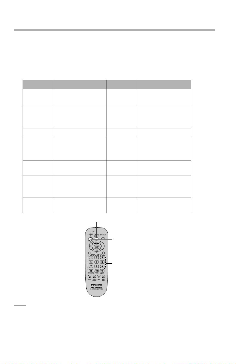
1.2 Remote Control
(1)
1 Names and Locations
(8)
(9)
(10)
(2)
(3)
(4)
(5)
(6)
(7)
(11)
(12)
(13)
(14)
1. [POWER] and [INPUT]:
You can program the remote control to turn your TV on and off when the
[POWER] button is pressed, and to change the TV's video input. You must first
program your TV's manufacturer code (see page page 18).
2. [MENU]: Press while monitoring a camera to display the [MENU] screen.
3. Number keys: Depending on the current screen, used to enter numbers and
text, or aim the camera at a preset position or at the sensor position (see page
page 59).
4. [TIMER]: Turns the timer on and off.
5. [0]: Displays the camera list or switches to multi-camera display mode.
6. [STOP]: Stops recording and playback.
7. [PLAY/PAUSE]: Starts and pauses movie playback and picture display.
8. [DISPLAY]: Toggles through the different image data display modes while
monitoring a camera (see page page 122).
[For assistance, please call: 1-800-272-7033] 15
Page 16

1 Names and Locations
9. Navigator keys: Used to select on-screen items or aim the camera in a
different direction.
10. [ENTER]: Depending on the current screen, selects the highlighted setting or
item, saves the current setting, or aims the camera at the home position (see
page 59).
11. [RETURN] Returns to the previous or menu.
12. [ALERT]: Turns the buzzer on and off. The buzzer can be used to alert you to
camera sensor detection.
13. [REC]: Press while monitoring a camera to record a movie.
14. [SNAPSHOT]: Press while monitoring a camera to take a picture.
Insert the batteries
While pulling the cover
toward you, lift it up.
Active range
The remote control can be used up to 7 m (23 ft.) away and within a 30 degree
angle from the remote control sensor.
16
Insert the batteries,
orienting the + and poles as indicated.
Remote control sensor
30˚ 30˚
Align the cover and
press down until it
snaps into place.
Signal
transmitter
Page 17

1 Names and Locations
Note
• Do not place anything between the remote control sensor and the remote
control.
• Do not expose the remote control sensor to direct sunlight or powerful invertertype fluorescent light.
• Should dust or grime accumulate on the remote control sensor and/or the
remote control transmitter, the effective range will be shortened.
• To clean, wipe the remote control sensor and transmitter with a clean dry cloth.
• If the BL-WV10A is placed in a cabinet, the thickness and/or color of the glass
doors of the cabinet may decrease the effective range of the remote control.
• The effective range of the remote control may decrease when the batteries are
losing their charge.
[For assistance, please call: 1-800-272-7033] 17
Page 18
1 Names and Locations
Programming the remote control
The remote control can be used to turn a television on and off, and to switch the
television’s video input selection. If your television is not a Panasonic television,
you can set the manufacturer’s code for the remote control.
While holding down [POWER], enter the 2-digit code found in the chart below that
corresponds to your TV. Release [POWER] after you have entered the code.
Code Manufacturer Code Manufacturer
01
02
03 Magnavox
Panasonic
Quasar
10 Sanyo
Fisher
11 JVC
Sylvania
Philips
04 Zenith 12 Hitachi
05 Thomson
13 Mitsubishi
RCA
GE
06
Sharp 14 Samsung
07
08 Sony 15
16
Goldstar
LG
17
09 To sh i b a 18
Samsung
19
[INPUT SELECT]
[POWER]
Number keys
Note
• When using the remote control to operate a television, aim the remote control
at the television.
18
Page 19

1 Names and Locations
• Some manufacturers have multiple codes. If the code you entered does not
work, please select one of the other codes for that manufacturer.
• If the television’s manufacturer is not listed above, please use the remote
control supplied with the television.
• If the batteries are removed from the remote control for thirty minutes or longer,
the remote control setting will be reset and you will need to enter the
manufacturer’s code again.
Using the remote control
Below is an example of how the remote control is used to navigate through onscreen menus.
Example:
Press [ENTER] to enter the [Camera List] screen.
[ENTER]
Navigator keys
Operation hints are shown here.
Remote control buttons and keys that can be used are shown here.
[For assistance, please call: 1-800-272-7033] 19
Page 20

2 Connecting Cameras
2 Connecting Cameras
Up to 8 cameras can be registered to the BL-WV10A.
To use the BL-WV10A, you will need to configure the network settings for the BL-
WV10A as well as store the user names and passwords for cameras connected to
the BL-WV10A. This can be done automatically using Quick Setup.
Quick Setup can be done in one of 3 different ways, depending on how the cameras
are connected.
Connecting cameras directly to the BL-WV10A
BL-WV10A
TV
To connect cameras directly to the BL-WV10A, see page 23.
Connecting cameras using an optional BB-HGW700A Camera Control Unit
Internet
BB-HGW700A
PC
BL-WV10A
TV
To connect a BB-HGW700A, see page 31.
Note
• Only 1 BB-HGW700A can be connected to the BL-WV10A wirelessly.
20
Page 21

2 Connecting Cameras
Connecting cameras using a router
Internet
Router
PC
BL-WV10A
TV
To connect to a router, see page 42.
Note
• The only wireless router that can be used with the BL-WV10A is the
Panasonic BB-HGW700A. All other routers require a wired connection.
[For assistance, please call: 1-800-272-7033] 21
Page 22

2 Connecting Cameras
2.1 Local and Remote Cameras
Cameras accessed by the BL-WV10A are referred to as either “local” or “remote”
cameras, based on the way in which they are configured.
Local cameras allow you to not only monitor images, but can be used in
conjunction with the various features of the BL-WV10A. Remote cameras, such as
cameras accessed over the Internet, can be monitored, but certain BL-WV10A
features may not be available with remote cameras.
INTERNET
Router
User Name: AAAAAA
Password: BBBBBB
Local Camera
Camera's User Name and
Password is the same as the
BL-WV10A's Admin. User
BL-WV10A
Admin. User Name: AAAAAA
Admin. Password: BBBBBB
Local Area Network (LAN)
Note
• If the firmware version of a BL-C10A or BL-C30A is older than 1.22, [This
camera's firmware is out of date] will be displayed and the camera will be
registered as a remote camera.
• HCM series cameras with firmware older than version 1.08, as well as
zoom cameras, can be registered as remote cameras only.
• User names and passwords shown here are examples only.
Name and Admin. Password
Remote Camera
Cameras connected via an Internet connection
User Name: WWWWWW
Password: XXXXXX
Remote Camera
Camera's User Name and
Password is different from
the BL-WV10A's Admin. User
Name and Admin. Password
Local Camera
Cameras configured using the BL-WV10A's
Quick Setup utility (some exceptions apply)
22
Page 23

2 Connecting Cameras
2.2 Connecting Cameras Directly to the BLWV10A
Below is an overview of the procedure for configuring cameras with the Quick
Setup feature for cameras connected directly to the BL-WV10A.
2.2.1 Connection Overview
1. Connect the BL-WV10A to a television (see page 23) and turn on the BL-
WV10A.
• The [Basic Setup] screen appears.
2. Run Quick Setup (see page 26).
3. Confirm that the camera images can be viewed with the BL-WV10A (see
page 28).
4. Place the camera where you plan on using it permanently (see page 30).
2.2.2 Television Connection
1. Connect the video cable from the BL-WV10A video output port to the
television’s video input (yellow) jack.
To external
video input
of TV
TV
2. Turn on the television.
[For assistance, please call: 1-800-272-7033] 23
Video output port
Rear panel of BL-WV10A
Video cable
Page 24

2 Connecting Cameras
3. Switch the television input mode to video.
To power outlet
(AC 110 V)
Mode switchDC IN jack
AC cord
AC adaptor
DC plug
4. Confirm that the mode switch on the back of the BL-WV10A is set to [SETUP].
5. Insert the DC plug from the AC adaptor into the DC IN jack in the BL-WV10A.
6. Connect the AC cord to the AC adaptor and plug it in.
• The [Basic Setup] screen will appear on the television.
Note
• Once Quick Setup is completed, the [Basic Setup] screen will not appear
again. Settings can be confirmed and changed from the [Setup] screen
(see page 95). In order to display the [Basic Setup] screen again, you will
need to restore the BL-WV10A’s default settings (see page 131).
24
Page 25

2 Connecting Cameras
7. Select [Finished] and press [ENTER].
• The confirmation screen will appear.
8. Select [Yes] and press [ENTER].
• Quick Setup will start.
Note
• Changing the IP address in the Shared Camera Settings Screen will
prevent a camera from being registered as a local camera during Quick
Setup. We recommend leaving the IP address at its default value.
[For assistance, please call: 1-800-272-7033] 25
Page 26

2 Connecting Cameras
2.2.3 Quick Setup
Once basic setup is complete, Quick Setup will automatically launch for network
and wireless settings. Setup will be complete in approximately 2 minutes.
• Once registration is complete, [Finished] will be displayed, the buzzer will
sound, and the wireless indicator will turn green.
Upon completion
of Quick Setup for
network and
wireless settings,
[Finished] will be
displayed.
1. Connect a camera (using the Ethernet cable supplied with the camera) to any
of the LAN jacks on the BL-WV10A.
2. Turn on the camera.
• Quick Setup will configure the camera and restart it if necessary.
Rear panel of
BL-WV10A
LAN jacks Rear panel
of camera
26
Switch
Bottom of BL-C30A
Ethernet cable
To configure a BL-C30A wireless camera
using the Quick Setup utility, set the switch
on the bottom of the camera to [WIRED]
Page 27

2 Connecting Cameras
Note
• If a user name and password has already been established for a camera,
Quick Setup will be unable to replace that data with the user name and
password for the BL-WV10A.
To register the camera as a local camera, reset the camera by pressing its
FACTORY DEFAULT RESET button before connecting it.
• Quick Setup can take place within 20 minutes after the camera is turned
on. If the camera is not recognized, or if [Restarting camera] is displayed
at the bottom of the screen for more than 2 minutes without camera
registration beginning, reset the camera by pressing its FACTORY
DEFAULT RESET button and reconnect the camera.
• If a camera needs to be restarted during Quick Setup, camera
configuration and restart will take about 2 minutes.
• During Quick Setup, the wireless indicator will light in green.
• Once registration is complete, the buzzer will sound and the wireless
indicator will flash green.
When camera
registration is
complete,
[Finished] is
displayed.
3. To register an additional camera, connect the Ethernet cable to the new
camera and turn the camera on.
• When registration is complete, the buzzer will sound and the wireless
indicator will flash once for each of the cameras registered.
[For assistance, please call: 1-800-272-7033] 27
Page 28

2 Connecting Cameras
• Cameras must be connected and configured by Quick Setup one at a time.
LAN jacks
Rear panel
of BL-WV10A
Ethernet cable
(included)
Rear panel of camera
4. Once all of the cameras have been registered as in step 3, turn the BL-
WV10A off.
2.2.4 Confirming the Camera Image
1. Connect all cameras registered during Quick Setup and turn them all on.
BL-WV10A
Note
• To use a wireless connection for the BL-C30A wireless camera,
disconnect it from the Ethernet cable, set the camera switch to
[WIRELESS] and turn the camera on again.
Video cable
Ethernet cable
TV
28
Switch
Bottom of BL-C30A
Page 29

2 Connecting Cameras
2. Set the mode switch on the back of the BL-WV10A to [NORMAL] and turn it
on.
• After the startup screen, the camera monitoring screen will appear.
Note
• As the cameras start up, those registered in camera list 1 will display a
monitoring image. If multiple cameras were registered, confirm that
monitoring images for all of the cameras registered in the multi-camera
screen (see page 64) are displayed.
• If the BL-WV10A does not receive date and time information from any of
the connected cameras, the [Date and Time] screen will appear. Select
the current date and time using the navigator keys on the remote control,
and press [ENTER] when finished.
• If [DST] is turned on, the BL-WV10A will automatically adjust its clock for
Daylight Saving Time. The clock will move forward 1 hour at 2:00 AM on
the first Sunday in April, and will move back 1 hour at 3:00 AM on the last
Sunday in October.
• If a camera image does not appear, check the connection and then restart
the camera. If the image still fails to appear, reset the camera to its default
values, and re-register it using Quick Setup.
• The date and time is displayed in the upper-right corner of the BLWV10A’s menu. If the date and time setting is not correct, set the correct
date and time from the [Date and Time] screen on the [Settings] screen
(see page 96).
Current date
and time
[For assistance, please call: 1-800-272-7033] 29
Page 30

2 Connecting Cameras
2.2.5 Placing Cameras
Place cameras after confirming the camera image (see page 28).
1. Disconnect the cameras and place them where you wish to use them.
• Refer to page 6 in this manual as well as the Operating Instructions
included with the camera for proper placement.
2. Connect all wired cameras to the BL-WV10A.
3. Set the mode switch on the back of the BL-WV10A to [NORMAL] and turn it
on.
4. Turn on the cameras.
5. Confirm that each camera can be accessed by the BL-WV10A.
• Camera information can be displayed by pressing [DISPLAY] while
monitoring a camera. When placing a wireless camera, refer to the signal
strength displayed on-screen for optimum transmission quality.
Transmission problems can result in connection faults and problems when
monitoring the camera.
Signal
strength
30
Strongest signal Weakest signal No signal
Page 31

2 Connecting Cameras
2.3 Connecting Cameras Using an Optional BBHGW700A
Note about connecting a BB-HGW700A
• Before registering existing cameras connected to the BB-HGW700A to the BLWV10A, make sure the cameras can be accessed with your computer. You may
also set the cameras to be accessible over the Internet if so desired. Refer to
the Operating Instructions included with your cameras and BB-HGW700A for
more information.
• When connecting a BB-HGW700A with a wired connection:
- A maximum of 8 cameras can be registered and accessed by the BLWV10A.
- Turn the BB-HGW700A’s wireless mode off.
• When connecting a BB-HGW700A wirelessly:
- Only 1 BB-HGW700A can be connected to the BL-WV10A.
- We recommend connecting 1 camera only (wired or wireless) to the BBHGW700A, and a maximum of 3 wireless cameras to the BL-WV10A.
- We recommend setting the BL-WV10A's wireless format setting to
802.11g for best results.
2.3.1 Connection Overview
1. Connect the BL-WV10A to the television and to the BB-HGW700A (see
page 32)
• The [Basic Setup] screen appears.
2. Set the user name and password (see page 34)
• If the cameras in use are already connected to the BB-HGW700A, change
the camera user names and passwords to the administrator name and
password for the BL-WV10A and run Quick Setup. If you run Quick Setup
without making these changes, the registered cameras will become
remote cameras.
• If the cameras are still set to the default settings, Quick Setup will
automatically assign user names and passwords without a need for you to
set the administrator name and password.
• Images from cameras for which the user names and passwords are
automatically set cannot be monitored with a computer.
3. Configure the BB-HGW700A and connected cameras using Quick Setup (see
page 35)
• Quick Setup for cameras and the BB-HGW700A.
[For assistance, please call: 1-800-272-7033] 31
Page 32

2 Connecting Cameras
4. Confirm the camera image (see page 38)
5. Place the BB-HGW700A and the cameras (see page 41)
2.3.2 Television and BB-HGW700A Connection
1. Connect the video cable from the BL-WV10A video output port to the
television’s video input (yellow) jack.
To external
video input
of TV
TV
Video output port
Rear panel of BL-WV10A
Video cable
2. Connect the Ethernet cable supplied with the BB-HGW700A to any of the LAN
jacks on the BL-WV10A and turn on the BB-HGW700A.
Rear panel of
BL-WV10A
• Turn on all cameras connected to the BB-HGW700A.
LAN jacks
To power outlet
(AC 110 V)
Rear panel of
BB-HGW700A
Ethernet cable
3. Turn on the television.
4. Switch the television input mode to video.
5. Confirm that the mode switch on the back of the BL-WV10A is set to [SETUP].
6. Insert the DC plug from the AC adaptor into the DC IN jack of the BL-WV10A.
• Make sure 2 minutes have passed since you turned on the BB-HGW700A.
32
Page 33

7. Connect the AC cord to the AC adaptor and plug it in.
DC IN jack
To power outlet
(AC 110 V)
2 Connecting Cameras
AC cord
AC adaptor
BB-HGW700A
• The [Basic Setup] screen will appear on the television.
Note
• Once Quick Setup is completed, the [Basic Setup] screen will not appear
again. Settings can be confirmed and changed from the [Setup] Menu
(page 95).
DC plug
[For assistance, please call: 1-800-272-7033] 33
Page 34

2 Connecting Cameras
2.3.3 Setting the User Name and Password
If there is no need to change any settings, proceed to steps 7 and 8 to
complete the Basic Setup.
Note
• If the cameras are set to their default settings, user names and passwords
will be automatically assigned without a need for you to set the
administrator name and password. Images from cameras for which the
user names and passwords are not equal to the administrator name and
password, however, will not be visible with a computer. To view camera
images on a computer, Quick Setup must be performed after setting the
administrator name and password for the camera.
• User names and passwords are case sensitive.
1. Select [Camera Settings] in the Basic Setup and press [ENTER].
• The [Camera Settings] screen will appear.
2. Select [Admin. User Name] and press [ENTER].
• The character input screen is displayed.
3. Enter the user name (to learn more about character entry, see page 121).
4. Select [Admin. Password] and press [ENTER].
• The character input screen is displayed.
34
Page 35

2 Connecting Cameras
5. Enter the password and press [ENTER].
6. Press [RETURN].
• You will return to the [Basic Setup] screen.
7. Select [Finished] and press [ENTER].
• The confirmation screen will appear.
8. Select [Yes] and press [ENTER].
• Quick Setup will start.
Note
• The administrator name and password must be between 6 and 15
alphanumeric characters in length. The following characters cannot be
used:
" < > : &.
2.3.4 Quick Setup
After completing Basic Setup, Quick Setup for the BB-HGW700A will start.
• Setup will be complete in approximately 2 minutes. Once registration is
complete, [Finished] will be displayed, the buzzer will sound, and the wireless
indicator will turn green.
Once Quick Setup for
the BB-HGW700A is
complete, [Finished] is
displayed.
• Cameras registered to the BB-HGW700A will be automatically registered to the
BL-WV10A.
[For assistance, please call: 1-800-272-7033] 35
Page 36

2 Connecting Cameras
1. Connect the cameras using the Ethernet cables provided with them to any of
the LAN jacks on the BL-WV10A or BB-HGW700A.
• Connect the cameras while the BB-HGW700A is connected to the BLWV10A.
Rear panel of
BL-WV10A
LAN jacks
Ethernet cable
Ethernet cable
Rear of camera
Switch
Rear panel of BB-HGW700A
2. Turn on the cameras.
• Quick Setup will register each camera.
Note
• If a camera needs to be restarted during Quick Setup, camera
configuration and restart will take about 2 minutes.
• During Quick Setup, the wireless indicator will be green.
Bottom of BL-C30A
To configure a BLC30A wireless camera
using the Quick Setup
utility, set the switch on
the bottom of the
camera to [WIRED]
36
Page 37

2 Connecting Cameras
• Once registration is complete, the buzzer will sound and the wireless indicator
will flash green.
When camera
registration is
complete,
[Finished] is
displayed.
Note
• Quick Setup can take place within 20 minutes of turning on a camera. If
the camera is not recognized, or if [Restarting camera] is displayed at the
bottom of the screen for more than 2 minutes without camera registration
beginning, reset the camera to its default settings and reconnect the
camera.
3. To register additional cameras, connect the Ethernet cable to the new
camera, and turn it on.
• When registration is complete, the buzzer will sound and the wireless
indicator will flash once for each of the cameras registered.
4. Once all of the cameras have been registered as in step 3, turn the BL-
WV10A off.
Note
• Cameras for which the user name and password matches that of the BLWV10A will be automatically registered within the camera list as local
cameras. (Non-matching cameras will be registered as remote cameras.)
• Cameras registered as remote cameras will remain so even if the user
name and password are changed to match those of the BL-WV10A. To reregister a camera as a local camera, see page 53.
[For assistance, please call: 1-800-272-7033] 37
Page 38

2 Connecting Cameras
2.3.5 Confirming the Camera Image
1. Disconnect all of the Ethernet cables from the BB-HGW700A.
2. Make sure the BL-WV10A is turned off.
3. Connect the LAN cables to the devices as necessary but do not turn them on.
4. Turn on the cameras connected to the BB-HGW700A.
5. Turn on the BB-HGW700A.
6. Set the mode switch on the back of the BL-WV10A to [NORMAL] and turn it
on.
7. Turn on the cameras connected to the BL-WV10A.
BL-WV10A
BB-HGW700A
Note
• To use a wireless connection for the wireless camera BL-C30A,
disconnect it from the Ethernet cable, set the camera switch to
[WIRELESS] and turn the camera on again.
Switch
Bottom of BL-C30A
Video cable
Ethernet
cable
TV
38
Page 39

2 Connecting Cameras
• After the BL-WV10A starts up, the camera monitoring screen will appear.
Note
• As the cameras start up, those registered in camera list 1 will display a
monitoring image. If multiple cameras were registered, confirm that
monitoring images for all of the cameras registered in the multi-camera
screen (see page 64) are displayed.
• If the BL-WV10A does not receive date and time information from any of
the connected cameras, the [Date and Time] screen will appear. Select
the current date and time using the navigator keys on the remote control,
and press [ENTER] when finished.
[For assistance, please call: 1-800-272-7033] 39
Page 40

2 Connecting Cameras
• If [DST] is turned on, the BL-WV10A will automatically adjust its clock for
Daylight Saving Time. The clock will move forward 1 hour at 2:00 AM on
the first Sunday in April, and will move back 1 hour at 3:00 AM on the last
Sunday in October.
• If a camera image does not appear, check the connection and then restart
the camera. If the image still fails to appear, reset the camera to its default
values, and re-register it using Quick Setup.
• The date and time is displayed in the upper-right corner of the BLWV10A’s menu. If the date and time setting is not correct, set the correct
date and time from the [Date and Time] screen on the [Settings] screen
(see page 96).
Current date
and time
40
Page 41

2 Connecting Cameras
2.3.6 Placing the BB-HGW700A and the Cameras
Place cameras after confirming the camera image (see page 38).
1. Turn off the BL-WV10A, BB-HGW700A, and cameras.
2. Place the BB-HGW700A and the cameras where you wish to use them.
• Refer to page 6 in this manual as well as the Operating Instructions
included with the camera for proper placement.
3. Make sure the BL-WV10A is turned off.
4. Connect the LAN cables to the devices as necessary but do not turn them on.
5. Turn on the cameras connected to the BB-HGW700A.
6. Turn on the BB-HGW700A.
7. Set the mode switch on the back of the BL-WV10A to [NORMAL] and turn it
on.
8. Turn on the cameras connected to the BL-WV10A.
9. Confirm that each camera can be accessed from the BL-WV10A.
• Camera information can be displayed by pressing [DISPLAY] while
monitoring a camera. When placing a wireless camera, refer to the signal
strength displayed on-screen for optimum transmission quality.
Transmission problems can result in connection faults and problems when
monitoring the camera.
Signal
strength
Strongest signal Weakest signal No signal
• If camera images are not smooth, repeat the procedure in this section and
try again. If the problem still persists and you are using wireless cameras,
refer to the information on page 6.
[For assistance, please call: 1-800-272-7033] 41
Page 42

2 Connecting Cameras
2.4 Connecting Cameras Using a Router
Note about connecting a router
• Before registering existing cameras, assign Static IP addresses to the
cameras, and set the cameras to be accessible over the Internet if so desired.
Refer to the Operating Instructions included with your cameras and router for
more information.
2.4.1 Connection Overview
1. Connect the BL-WV10A to the television and router (see page 42)
• The [Basic Setup] screen appears.
2. Set the camera IP address (see page 44)
3. Set the user name and password (see page 45)
• If the cameras in use are already connected to a router, change the
camera user names and passwords to the administrator name and
password for the BL-WV10A and run Quick Setup. If you run Quick Setup
without making these changes, the registered cameras will become
remote cameras.
• If the cameras are still set to the default settings, Quick Setup will
automatically assign user names and passwords. There is no need to set
the administrator name and password manually.
4. Configure the cameras using Quick Setup (see page 47)
5. Confirm the camera images (see page 50)
6. Place the cameras and the router (see page 52)
2.4.2 Television and Router Connection
1. Connect the video cable from the BL-WV10A video output port to the
television’s video input (yellow) jack.
To external
video input
of TV
TV
42
Video output port
Rear panel of BL-WV10A
Video cable
Page 43

2 Connecting Cameras
2. Connect the Ethernet cable that came with the router to any of the LAN jacks
on the BL-WV10A and turn on the router.
Rear panel of
BL-WV10A
LAN jacks
To power outlet
(AC 110 V)
Rear panel of router
Ethernet cable
3. Turn on the television.
4. Switch the television input mode to video.
5. Confirm that the mode switch on the back of the BL-WV10A is set to [SETUP].
6. Insert the DC plug from the AC adaptor into the DC IN jack in the BL-WV10A.
7. Connect the AC cord to the AC adaptor and plug it in.
DC IN jack
To power outlet
AC cord
AC adaptor
[For assistance, please call: 1-800-272-7033] 43
DC plug
Router
Page 44

2 Connecting Cameras
• The [Basic Setup] screen will appear on the television.
Note
• Once Quick Setup is completed, the [Basic Setup] screen will not appear again.
Settings can be confirmed and changed from the [Setup] menu (see page 95).
2.4.3 Setting the Camera’s IP Address
1. On the [Basic Setup] screen, select [Camera Settings], and press [ENTER].
• The [Camera Settings] screen will appear.
2. Select [Starting Address] and press [ENTER].
• The [Starting Address] screen will appear.
44
Page 45

2 Connecting Cameras
3. Enter the IP address for the camera and press [ENTER].
• Use an address with the same DHCP address segment as used by the
router, but make sure that address is not assigned in DHCP.
• The address entered here will be assigned to the first camera configured
using Quick Setup. Additional cameras will be assigned sequential
addresses.
• If you’re uncertain which addresses to use, ask the router’s manufacturer
how to confirm router settings and address usage.
2.4.4 Setting the User Name and Password
Note
• If the cameras are set to their default settings, user names and passwords
will be automatically assigned without a need for you to set the
administrator name and password. Images from cameras for which the
user names and passwords are not equal to the administrator name and
password, however, will not be visible with a computer. To view camera
images on a computer, Quick Setup must be performed after setting the
administrator name and password for the camera.
• User names and passwords are case sensitive.
1. On the [Basic Setup] screen, select [Camera Settings], and press [ENTER].
• The [Camera Settings] screen will appear.
[For assistance, please call: 1-800-272-7033] 45
Page 46

2 Connecting Cameras
2. Select [Admin. User Name] and press [ENTER].
• The character input screen is displayed.
3. Enter the user name (to learn more about character entry, see page 121).
4. Select [Admin. Password] and press [ENTER].
• The character input screen is displayed.
5. Enter the password and press [ENTER].
6. Press [RETURN].
• You will return to the [Basic Setup] screen.
7. Select [Finished] and press [ENTER].
• The confirmation screen will appear.
8. Select [Yes] and press [ENTER].
• Quick Setup will start.
Note
• The administrator name and password must be between 6 and 15
alphanumeric characters in length. The following characters cannot be
used:
" < > : &.
Note
• If the cameras are set to the default settings, user names and passwords will
be automatically assigned without a need for you to set the administrator name
and password. Images from cameras for which the user names and passwords
are not equal to the administrator name and password, however, will not be
visible with a computer. To view camera images on a computer, Quick Setup
must be performed after setting the administrator name and password (using a
minimum of 6 characters each) for the camera.
46
Page 47

2 Connecting Cameras
2.4.5 Quick Setup
After completing Basic Setup, Quick Setup will automatically launch and configure
the router settings.
• Setup will be complete in approximately 2 minutes. Once registration is
complete, [Finished] will be displayed, the buzzer will sound, and the wireless
indicator will turn green.
Note
• The BL-WV10A will automatically search out and use a fixed IP address after
the router obtains network data via the DHCP feature of the router.
Upon completion
of Quick Setup for
network and
wireless settings,
[Finished] will be
displayed.
Note
• Cameras connected to the router and for which setup has completed will be
automatically registered for the BL-WV10A. Cameras not set up for static
address will be automatically registered, but it is possible that they may lose the
connection during use. Either change the camera settings to those for a static
address, or reset the camera to its default settings by pressing the camera’s
FACTORY DEFAULT RESET button and use Quick Setup to configure the
camera again.
[For assistance, please call: 1-800-272-7033] 47
Page 48

2 Connecting Cameras
1. Connect the cameras using the Ethernet cables provided with them to any of
the LAN jacks on the on the BL-WV10A.
2. Turn on the cameras.
• Quick Setup will begin for the camera.
Rear panel of
BL-WV10A
LAN jacks
Ethernet cable
Ethernet cable
Rear of camera
Switch
Bottom of BL-C30A
To configure a BLC30A wireless camera
using the Quick Setup
utility, set the switch on
the bottom of the
camera to [WIRED]
Note
• During camera registration, the camera may be restarted, and registration
may take longer as a result. A camera restart can take up to 2 minutes.
• During Quick Setup, the wireless indicator will be green.
Router
48
Page 49

2 Connecting Cameras
• Once registration is complete, the buzzer will ring, and the wireless
indicator will flash green.
When camera
registration is
complete,
[Finished] is
displayed.
Note
• Quick Setup can take place within 20 minutes of powering on the camera.
If the camera is not recognized, or if [Restarting camera] is displayed at
the bottom of the screen for more than 2 minutes without camera
registration beginning, reset the camera to its default settings and
reconnect the camera.
3. To register additional cameras, connect the Ethernet cable to the new
camera, and turn it on.
• When registration is complete, the buzzer will sound and the wireless
indicator will flash once for each of the cameras registered.
4. Once all of the cameras have been registered as in step 3, turn the BL-
WV10A off.
Note
• Cameras for which the user name and password matches that of the BLWV10A will be automatically registered within the camera list as local
cameras. (Non-matching cameras will be registered as remote cameras.)
• Cameras registered as remote cameras will remain so even if the user
name and password are changed to match those of the BL-WV10A. To reregister a camera as a local camera, see page 53.
[For assistance, please call: 1-800-272-7033] 49
Page 50

2 Connecting Cameras
2.4.6 Confirming the Camera Image
1. Turn on the router and the cameras connected to the router.
Video
BL-WV10A
cable
Router
Ethernet
cable
Ethernet
cable
TV
2. Set the mode switch on the back of the BL-WV10A to [NORMAL] and turn it
on.
3. Turn on the cameras connected to the BL-WV10A.
Note
• To use a wireless connection for the wireless camera BL-C30A,
disconnect it from the Ethernet cable, set the camera switch to
[WIRELESS] and turn the camera on again.
Switch
Bottom of BL-C30A
• After the launch screen, the Camera Monitoring Screen will appear.
50
Page 51

2 Connecting Cameras
Note
• As the cameras start up, those registered in camera list 1 will display a
monitoring image. If multiple cameras were registered, please confirm that
monitoring images for all of the cameras registered in the Multi-Camera
Screen (see page 64) are displayed.
• If the BL-WV10A does not receive date and time information from any of
the connected cameras, the [Date and Time] screen will appear. Select
the current date and time using the navigator keys on the remote control,
and press [ENTER] when finished.
• If a camera image does not appear, check the connection and then restart
the camera. If the image still fails to appear, reset the camera to its default
values, and re-register it using Quick Setup.
• The date and time is displayed in the upper-right corner of the BLWV10A’s menu. If the date and time setting is not correct, set the correct
date and time from the [Date and Time] screen on the [Settings] screen
[For assistance, please call: 1-800-272-7033] 51
Page 52

2 Connecting Cameras
(see page 96).
Current date
and time
2.4.7 Placing the Router and the Cameras
Place cameras after confirming the camera image (see page 50) and the router
after confirming it has been correctly registered and connected.
1. Place the router and the cameras.
• Refer to page 6 in this manual as well as the Operating Instructions
included with the camera for proper placement.
2. Make sure the BL-WV10A is turned off.
3. Connect the LAN cables to the devices as necessary but do not turn them on.
4. Turn on router and all cameras connected to the router.
5. Set the mode switch on the back of the BL-WV10A to [NORMAL] and turn it
on.
6. Turn on the cameras connected to the BL-WV10A.
7. Confirm that each camera can be accessed from the BL-WV10A.
• Camera information can be displayed by pressing [DISPLAY] while
monitoring a camera. When placing a wireless camera, refer to the signal
strength displayed on-screen for optimum transmission quality.
Transmission problems can result in connection faults and problems when
monitoring the camera.
52
Signal
strength
Strongest signal Weakest signal No signal
Page 53

2 Connecting Cameras
2.5 Re-registering a Remote Camera as a Local
Camera
There are 2 ways to re-register remote cameras within the network as a local
camera. (For definitions of local and remote cameras, see page 22.)
1. Access the camera with a computer and change its user name and password
to match the administrator name and password for the BL-WV10A that you set
during Basic Setup.
2. Erase the camera from the camera list (see page 118).
3. Re-register the camera using Quick Setup (see page 26, page 35, or page 47
depending on your connection method).
Or…
1. Erase the registration from the camera list (see page 118).
2. Revert the camera to its default settings.
3. Re-register the camera using Quick Setup (see page 26, page 35, or page 47
depending on your connection method).
[For assistance, please call: 1-800-272-7033] 53
Page 54

3 Viewing Camera Images
3 Viewing Camera Images
Once Quick Setup is complete, set the mode switch on the back of the unit to
[NORMAL], disconnect the DC plug from the back of the unit, then reconnect it.
After the unit starts up, the camera image will be displayed.
54
Note
• Frame rate (frames per second, “fps”) may vary depending on the image
being viewed by the camera, brightness, and other environment
conditions, as well as network conditions such as distance between the
BL-WV10A and the cameras, the number of cameras connected, network
traffic, wireless network conditions (see page 6), etc.
• For BL-C10A and BL-C30A, a maximum of 15 fps in LOW quality
(resolution) and 7.5 fps in HIGH quality is possible (see page 124).
• For HCM series cameras, a maximum of 30 fps in LOW quality and 12 fps
in HIGH quality is possible (see page 124).
• Network speed may decrease while the BL-WV10A is turned on and
connected to cameras.
• The display size and brightness of the Monitoring Screen can be adjusted
(see page 122).
Page 55

3 Viewing Camera Images
• If you changing the mode switch to [SEQ. DISP.] and turn the power off
and back on, the camera will cycle through all registered cameras
sequentially and display their images briefly.
[When Using a Computer and/or a Router]
• If remote cameras are registered in camera list 1 and those cameras are set to
not save passwords (see page 115), the BL-WV10A will display a password
input screen upon launch. After entering the camera’s user name and
password and pressing [OK], the Monitoring Screen will appear.
[
• Cameras for which Quick Setup was performed without setting the
administrator name and password will have user names and passwords set
automatically; their images cannot be monitored on a computer. Change the
camera’s user name (see page 134).
[For assistance, please call: 1-800-272-7033] 55
Page 56

3 Viewing Camera Images
3.1 Displaying the Menu Screen
Press [MENU] while viewing the monitoring screen.
• The Menu screen is displayed.
Camera List:
Select a camera from the list of registered cameras (see page 63).
Movies:
Displays recorded movies (see page 88). (If no SD memory card is inserted in the
unit, [Movies] is displayed in faint blue letters to indicate it cannot be selected.)
Pictures:
Displays recorded pictures (see page 92). (If no SD memory card is inserted in the
unit, [Pictures] is displayed in faint blue letters to indicate it cannot be selected.)
Recorder:
Sets timer recording and sensor-triggered recording (see page 71).
Sensor Alert:
When a camera’s built-in sensor detects a change in temperature, this feature can
automatically display the image from the camera (see page 66).
Setup:
Manages the time settings, the initial settings for the BL-WV10A, camera settings
and SD memory cards (see page 95).
Note
• The Menu screen cannot be displayed when either the camera list or MultiCamera Screen is visible.
• While the menu is displayed, press [STOP] to hide the camera image. To
show the image again, press [PLAY].
• The current time is displayed at the upper right of the Menu screen. If the
correct time has not been set, it can be adjusted by selecting [Date and
Time] in the Setup menu (see page 95).
56
Page 57

3 Viewing Camera Images
3.2 Panning/Tilting
While monitoring a camera you can pan and tilt the camera’s lens in order to aim
the camera at the object you want to view.
Pan:-50˚ – +50˚
Tilt:-40˚ – +10˚
Model shown is BL-C30A
Press the navigator keys
to pan or tilt the lens and
aim the camera.
Note
• If another user accesses the camera using a computer and pans or tilts
the camera lens, the image displayed by the BL-WV10A will change
accordingly.
[For assistance, please call: 1-800-272-7033] 57
Page 58

3 Viewing Camera Images
• If the lens alignment exceeds the maximum coordinates during panning or
tilting, notification will appear on screen for approximately 4 seconds.
When the camera is
panned to the right
end of the camera’s
range, "Right End" is
displayed.
[Setting Cameras from the Computer]
• If the camera has been set to disable pan and tilt control, you will be unable to
use panning and tilting functions. (Refer to the camera's Operating Instructions
for more information.) Access the camera via a computer and enable pan and
tilt functions.
58
Page 59

3 Viewing Camera Images
3.3 Home Position/Sensor Position/Preset Keys
The camera’s home position, sensor position and preset keys can be registered,
allowing to aim the camera at a predetermined location easily.
Home Position: The direction in which the lens is pointing when the camera is
turned on.
Sensor Position: The direction the lens is pointing when the camera sensor is
activated.
Preset Keys (8 total): You can register positions to correspond to the remote
control’s keypad.
Home position
([ENTER])
Press to aim the
camera at the home
position.
You can set the home
position to the current
position by holding
[ENTER] down for
about 5 seconds.
Presets
([1] to [8])
You can register up to
8 positions and aim
the camera by
pressing the
corresponding button.
[1] to [4] are preset
but can be changed.
[For assistance, please call: 1-800-272-7033] 59
Sensor position
([9])
Press to aim the
camera at the sensor
position. You can set
the sensor position to
the current location by
holding [9] down for
about 5 seconds.
Page 60

3 Viewing Camera Images
Registering the Home Position/Sensor Position
1. Using the navigator keys, pan and tilt the lens and aim it at the desired home
position.
2. To register the current position as the home position, hold the [ENTER] for
about 5 seconds. Press and hold [9] to register the current position as the
sensor position.
• A confirmation screen will appear.
Home Position Confirmation Screen
Sensor Position Confirmation Screen
3. Select [Yes] and press [ENTER] to confirm.
Note
• Use of the home and sensor positions stores data to the camera. When
multiple users are using the cameras, only the data for the last registration
will remain valid; other users can overwrite registered positions.
• You cannot set a camera so that its lens does not move to the sensor
position when the camera’s sensor is activated.
• Registering the home position and/or sensor position will also register the
brightness and white balance settings (see page 124) at the time of the
registration.
Registering the Preset Keys
The camera’s display positions can be registered to correspond to numbers of the
remote control keypad.
1. Using the navigator keys, pan and tilt the lens and aim it at the position you
would like to register to a preset key.
2. Hold the desired preset key number key ([1] to [8]) for roughly 5 seconds.
• A confirmation screen will appear.
• The currently set name for the preset will appear.
60
Page 61

3 Viewing Camera Images
• Select [Yes] to confirm the displayed preset name.
3. To set the preset name manually, select [Yes] and press [ENTER].
• The character input screen is displayed. Enter the preset name. (See
page 121 for text entry methods.)
4. Confirm the preset name, select [Yes] and press [ENTER].
Note
• A preset name can use up to 15 alphanumeric characters. The following
characters cannot be used:
" ' & < >.
• Use of the preset keys stores data to the camera. When multiple users are
using the cameras, only the data for the last registration will remain valid;
other users can overwrite registered presets.
• Registering a preset key will also register the brightness and white
balance settings (see page 124) at the time of the registration.
Viewing the home position
Press [ENTER] while monitoring a camera.
• The lens moves to the home position.
• [Home Position] is displayed in the upper left corner of the screen for about
4 seconds.
[For assistance, please call: 1-800-272-7033] 61
Page 62

3 Viewing Camera Images
Viewing the sensor position
Press [9] while monitoring a camera.
• The lens moves to the sensor position.
• [Sensor Position] is displayed in the upper left corner of the screen for
about 4 seconds.
Viewing a preset position
Press one of the registered number keys ([1] to [8]) while monitoring a camera.
• The lens moves to the preset position.
• For certain camera models, keys [1] to [4] are registered at the factory and
aim the camera to the upper left, upper right, lower left, and lower right
positions, respectively.
• The name of the preset will appear in the upper left corner of the screen
for about 4 seconds.
The settings for brightness and white balance will change to those at time of
registration.
62
Page 63

3 Viewing Camera Images
3.4 Choosing a Camera from the Camera List
1. Press [MENU].
• The menu is displayed.
2. Select [Camera List] and press [ENTER].
• The Camera List appears.
Note
• When you select a camera from the list, its monitoring screen appears in
the background.
• The order of the camera list can be changed (see page 119).
• Pressing [0] will display the camera list.
3. Select the desired camera and press [ENTER], or press the camera’s number
on the remote control.
• The monitoring screen appears.
[For assistance, please call: 1-800-272-7033] 63
Page 64

3 Viewing Camera Images
3.5 Displaying the Multi-Camera Screen
Press [0] while monitoring a camera to display the multi-camera screen.
• When either the Camera List or Multi-Camera Screens are visible, use the
navigator keys to select a camera, then press [ENTER] to monitor a single
camera.
When more than 4 cameras
are registered
Monitoring screen
Press
Press
Camera List
Note
• When viewing the Multi-Camera screen, images from HCM series
cameras will appear smoother and with less delay than images from BLC10A and BL-C30A cameras.
• You can set remote cameras to either save or not save their passwords
when they are connected (see page 115). If the password is not saved,
you will be prompted to enter the user name and password when you try
to access the camera.
0
Press
Multi-Camera screen 2
0
Multi-Camera screen 1
Remote2 Remote3
Remote4 Remote5
0
Press
0
64
Page 65

Multi-Cam View
When camera "Remote1" is selected.
3 Viewing Camera Images
Images will not be
displayed from remote
cameras which have
[Password Save] set
to [Off].
Enter the camera's user name and password in order to view the camera.
[For assistance, please call: 1-800-272-7033] 65
Page 66

3 Viewing Camera Images
3.6 Sensor Alert Mode
This feature is not available with HCM series cameras.
Sensor Alert uses the camera sensor functionality to automatically switch
monitoring cameras with sensor cameras.
Note
• When the sensor is activated the sensor indicator will flash.
• If the buzzer is on, the buzzer will also indicate that the sensor has been
activated (see page 69).
• The camera’s sensor detects heat variations which occur from the sides
with more accuracy than variations which approach the camera.
• The detection range of the sensor may increase or decrease depending
on the temperature and environment where the camera is installed.
1. Press [MENU].
• The menu is displayed.
2. Select [Sensor Alert] and press [ENTER].
• The Sensor Alert Screen appears.
66
Note
• To activate Sensor Alert, you will need to first turn on a sensor for at least
1 camera on the [Camera Sensors] screen.
Page 67

3 Viewing Camera Images
3. Select [Camera Sensors] and press [ENTER].
• The [Camera Sensors] screen appears.
4. Use the navigator keys to select either [On] or [–] (off) for each camera’s
sensor, then press [ENTER].
• The display returns to the [Sensor Alert] screen.
5. Use the navigator keys to select [On], then press [ENTER].
• After these settings are made, the Menu screen returns.
Note
• When Sensor Alert mode is set, the sensor indicator lights.
• The sensor range may differ depending on the camera type. See the
camera user guide for cautions in placing the camera to maximize that
range.
[For assistance, please call: 1-800-272-7033] 67
Page 68

3 Viewing Camera Images
Sensor Notification Screen
If a camera sensor detects motion when Sensor Alert mode is on, the Monitoring
Screen switches to the relevant camera, and that camera lens moves to the sensor
position. The sensor position is set as indicated on page 60.
Note
• After the Sensor Notification Screen is displayed, the camera is set to
repeat sensor responses every several seconds, and those responses will
not be displayed. The sensor must go for roughly 5 seconds without
activation. If another camera’s sensor is triggered, however, the display
will switch to that camera.
• If a camera's sensor triggers Sensor Alert mode, the camera's image will
not be displayed if:
- The TV's video input is not set to the input which the BL-WV10A is
connected to
- You are currently recording a camera image (using standard
recording)
- You are accessing the [Sensor Alert] or [Setup] screen.
- You are taking a snapshot
- You have set the timer record or sensor record feature.
In these situations, you will still be alerted to sensor detection by the flashing of the
sensor indicator and by the buzzer, if you have the buzzer turned on.
• When viewing the television, you cannot switch to a sensor-activated
screen. Press [INPUT] on the remote control to switch to the camera
Monitoring Screen.
• The buzzer volume can be adjusted (see page 97).
• If you have hidden the camera's image (see page 56), the camera's image
will be displayed if the sensor is triggered.
68
Page 69

3 Viewing Camera Images
Turning the buzzer on
Press [ALERT] to turn the buzzer on.
• The alert indicator will turn green.
Alert indicator
Sensor indicator
Stopping the Buzzer
Press [ALERT] to turn the buzzer off.
• The alert indicator light will go out.
• After turning the buzzer off, pressing [ALERT] again will turn it back on.
Changing the Buzzer Volume
Volume can be changed in the [General Setup] screen from the [Setup] screen.
The volume settings are Off, 1, 2, 3 and 4.
Turning off the Flashing Sensor Indicator
When Sensor Alert mode is on, or when using the sensor for set recording times
(see page 66 and page 76), the sensor indicator will continue to flash once the
camera’s sensor has been activated.
To turn it off:
1. Display the [Sensor Alert] screen (see page 66).
2. Set [Sensor Alert] to [–] (unless it is already set to [–]), then press [ENTER].
• To turn Sensor Alert mode on again, set [Sensor Alert] to [On] again on
the [Sensor Alert] screen.
Note
• A remote camera can be selected here only if [Sensor] is set to [On] on
the camera's setup screen (see page 117).
[For assistance, please call: 1-800-272-7033] 69
Page 70

3 Viewing Camera Images
[For Computer Users]
Note
• When a local camera is set to be used with the timer or sensor recording
feature, the camera's Trigger No. 5 (which can be set using your computer
by accessing the camera's [Buffer/Transfer] screen) is used for recording.
If you also use a computer to access your cameras, do not set Trigger No.
5. For more information refer to "Buffering or Transferring Images by
Timer" or "Buffering or Transferring Images by Sensor" in the Operating
Instructions included with your camera.
70
Page 71

4 Recording Images
4 Recording Images
There are 3 ways to record images: standard recording, snapshot recording and
timer recording.
Standard Recording:
Pressing the [RECORD] while monitoring a camera will record the images as a
movie (see page 75).
Snapshot Recording:
Pressing the [SNAPSHOT] while monitoring a camera will record a picture (see
page 75).
Timer Recording:
There are 2 types of timer recording (see page 76).
• Timer Trigger: Recording on specified dates only. Recording occurs for the
entire duration of the timer, or only when the sensor is triggered (not
available with HCM series cameras) during set duration.
• Sensor Trigger: Images are recorded only when the specified camera’s
sensor is activated (see page 81). Not available with HCM series
cameras.
Timer trigger
Example: When the timer is set to record between 8:30 and 10:30
When [RECORD TYPE]
is set to [All]:
When [RECORD TYPE]
is set to [Sensr]:
Records for entire duration
Sensor
detection
detection
Sensor
Sensor
detection
8:00
Sensor trigger
Sensor
detection
8:00 9:00 10:00
Record Record Record
Note
• A n SD memo r y ca r d must b e inser ted in t he unit i n order t o record camera
images.
• Timer recording can specify either timer recording or continuous sensor
recording, but not both. You must choose one or the other.
[For assistance, please call: 1-800-272-7033] 71
9:00 10:00
Record Record Record
Sensor
detection
Sensor
detection
Page 72

4 Recording Images
• See page 84 for more information on recording frame rates for sensor
recording.
Record Mode Resolution Image Refresh Interval
HIGH 640 x 480 1 sec.
LOW 320 x 240* 1 sec.
LONG 320 x 240* 5 sec.
*When recording in LOW or LONG mode, a smaller image is recorded and the
image appears smaller during playback.
• We recommend using a recording mode of either HIGH or LOW for sensor
recording.
4.1 SD Memory Cards
We recommend using Panasonic SD memory cards with the BL-WV10A.
(We cannot guarantee the performance of SD memory cards made by other
manufacturers.) Cards with capacities of up to 1 GB can be used.
Inserting an SD memory card
Timer/Access
indicator
Ejecting an SD memory card
Insert label
side up,
Push the SD memory card
slightly, then remove it
with notch
on right side
CAUTION
When the timer/access indicator is flashing amber, data is either being read from
or written to the card. When the indicator is flashing amber, do not do any of the
following:
• Remove the SD memory card.
• Turn off the BL-WV10A.
• Press the FACTORY DEFAULT RESET button.
Doing so can result in corrupted data on the SD memory card. If this occurs, the
card cannot be used and you will need to reformat the card with the BL-WV10A.
All data on the card will be erased.
Note
• Do not use the SD memory card used for the BL-WV10A in other devices
(digital cameras, video cameras, etc.). Only image data (movies and
pictures) that were recorded with the BL-WV10A can be viewed with the
72
Page 73

4 Recording Images
BL-WV10A. Image data saved on SD memory cards by other devices may
not be displayable on the BL-WV10A. Similarly, image data saved on the
SD memory card using the WV-10A may not be displayable on other
devices.
• FAT12 format and FAT16 format SD memory cards can be used with the
BL-WV10A.
• SD memory cards formatted by another device, such as a computer, may
not be able to be used with the BL-WV10A.
• We recommend that you format SD memory cards with the BL-WV10A
prior to use.
• When you remove the SD memory card, the screen will switch to the
monitoring screen.
• The length of time or the number of frames/pictures that can be recorded
onto an SD memory card is as indicated below. Those figures were
calculated for maximum image size. Image size and content may affect
recording time or the number of frames/pictures.
• There are no guarantees for recorded content. Issues with either the BLWV10A or a card that result in a loss of images cannot be compensated
for by Panasonic.
• During standard recording (I.e., pressing the [RECORD] button on the
remote control while monitoring a camera), images are recorded at the
displayed resolution ([HIGH] or [LOW]), however, the length of time for
recording is the same regardless of the resolution.
• In comparison to timer recording, standard recording captures much more
data; ordinary recording, therefore, will minimize any capacity needed for
timer recording. Always confirm the time available for recording on the
Timer Recording Confirmation Screen.
[For assistance, please call: 1-800-272-7033] 73
Page 74

4 Recording Images
Movie Recording Time
SD
Capacity
Timer/Sensor Recording Standard Recording
LONG LOW HIGH HCM Series C Series
8 MB 1 hr. 10 min. 3 min. 13 sec. 26 sec.
16 MB 2 hr.
30 min. 7 min. 30 sec. 58 sec.
30 min.
32 MB 5 hr.
1 hr. 10 min. 1 min. 2min.
10 min.
64 MB 10 hr.
2 hr. 30 min. 2 min. 4 min.
40 min.
128 MB 21 hr.
40 min.
256 MB 43 hr.
20 min.
512 MB 87 hr.
10 min.
1 GB 167 hr.
50 min.
4 hr.
20 min.
8 hr.
40 min.
17 hr.
20 min.
33 hr.
30 min.
1 hr. 4 min. 8 min.
2 hr. 8 min. 16 min.
4 hr.
17 min. 33 min.
10 min.
8 hr. 33 min. 65 min.
• See page 84 for more information on recording modes (LONG, LOW and
HIGH).
Picture Storage
SD
Capacity
No. of Pictures
LOW HIGH
8 MB 270 160
16 MB 450 300
32 MB 940 630
64 MB 1930 1290
128 MB 3900 2600
256 MB 7780 5190
512 MB 15680 10460
1 GB 30170 20120
74
Page 75

4 Recording Images
4.2 Standard Recording
During standard recording, images are recorded at the displayed resolution (see
page 124).
1. Insert an SD memory card into the BL-WV10A (see page 72).
2. While monitoring a single camera, press [RECORD].
• Recording begins.
Status indicator: Red
CAM1
Recording
3. To stop recording, press [STOP].
• A list of all movies can be viewed on the [Movies] screen (see page 88).
• Press [DISPLAY] while recording to display information on the recording
(see page 90).
Note
• Neither remove an SD memory card nor turn off the BL-WV10A while it is
in ordinary recording mode. Doing so will cancel the recording and may
corrupt the data on the card. If this occurs, you will need to reformat the
card with the BL-WV10A (see page 120).
• During standard recording, a maximum of 15 frames per second (fps) can
be recorded. Results will vary depending on network conditions.
Shown in upper-right corner
of screen for 4 seconds after
recording has started
4.3 Snapshot Recording
A picture of the image being monitored is saved to an SD memory card.
1. Insert an SD memory card into the BL-WV10A (see page 72).
2. Display the Monitoring Screen and press [SNAPSHOT].
Status indicator: Red
CAM1
Recording
• Upon pressing [SNAPSHOT], the image being monitored will be saved as
a picture to the SD memory card.
• A list of recorded pictures can be viewed on the [Pictures] screen (see
page 92).
[For assistance, please call: 1-800-272-7033] 75
Shown in upper-right corner
of screen while snapshot is
being taken
Page 76

4 Recording Images
Note
• Snapshot recording is not available when the Multi-Camera Screen is
visible (see page 64).
4.4 Timer Recording
Note
• If the BL-WV10A’s date and time setting (page 96) is set to use Daylight Saving
Time (i.e., if [DST] is turned on), actual recording time will be based on Daylight
Saving Time. Recordings may be up to 1 hour shorter than planned on the first
Sunday in April, and 1 hour longer on the last Sunday in October.
• If the SD memory card is removed while setting up for timer recording, the
setup screen will change to the Monitoring Screen, with all timer settings
cancelled.
4.4.1 Setup for Timer Recording
1. Insert an SD memory card into the BL-WV10A.
• An SD memory card is not needed if you are not recording to one (see
page 79).
2. Press [MENU].
• The menu is displayed.
76
Page 77

3. Select [Recorder] and press [ENTER].
• The Timer Recording Screen appears.
4 Recording Images
• See page 83 for more information on changing recording modes.
4. If [Sensor] is selected, select [Trigger Type] and press ENTER].
• The Trigger Type screen appears.
• Select [Timer] and press ENTER].
• The [Recorder] screen for timer recording appears.
[For assistance, please call: 1-800-272-7033] 77
Page 78

4 Recording Images
5. Select [New] and press [ENTER].
• The settings screen for timer recording appears.
Remaining SD memory card capacity (in minutes)
Current date
and time
6. Set the timer recording content.
• A maximum of 5 intervals can be recorded with timer recording.
Setting Content
Day of the Week Select the day for recording.
Use the navigator keys to select the desired option (daily,
every Sunday to every Saturday, Monday to Friday, Monday
to Saturday, Saturday and Sunday).
Camera Name Select the camera to be used for recording.
Start Time/End
Time
Set the times to begin and end recording.
Press the top and bottom navigator keys change the time in
1 minute increments.
Press and hold the top and bottom navigator keys to change
the time in 15 minute increments.
• Remote cameras for which passwords are not saved will not be displayed. If all
registered cameras are remote cameras for which passwords are not saved,
the following screen will appear. When using remote cameras for timer
78
Page 79

4 Recording Images
recording, change their settings such that passwords are saved (see
page 115).
Setting Content
Record Type Select the recording method.
All: Records all images from the camera during the time interval
specified.
Sensr (Sensor): Records images from the camera during the
time interval specified, but only when the sensor is activated.
SD Recording To record to an SD memory card, select [O].
To record to a different destination, select [—].
When [SENSOR] has been selected for content, only [O] is
available.
• The sensor range may differ depending on the camera type. To record
from remote cameras using sensor activation, confirm that the cameras
are set for sensor use (see page 117). See the camera user guide for
cautions in placing the camera to maximize that range.
• To record images from the Monitoring Screen to a video deck or a DVD/
HDD recorder, select [—]. Use a video cable to connect the video output
port on the BL-WV10A to the video input jack on a video deck or DVD/
HDD recorder, setting the time for recording on the video deck or DVD/
HDD recorder to match that of the BL-WV10A. At the set time, the
Monitoring Screen for the specified camera will appear and be recorded
on the video deck or DVD/HDD recorder.
7. After setting the content, press [ENTER].
• Timer recording is now set.
8. Press [TIMER] to turn the timer on.
• Upon doing so, the timer/access indicator will turn green.
[For assistance, please call: 1-800-272-7033] 79
Page 80

4 Recording Images
Note
• HCM series cameras cannot record by sensor. You can set sensor
recording on the BL-WV10A, but sensor recording will not occur.
• If the timer is turned on after the time for which recording was to begin,
recording will begin when the timer was turned on. If the timer is turned on
after the recording was to have ended, recording will begin at the next set
interval.
• If recording start and end times conflict with previously set times, “The
timer could not be set because the recording time overlaps with another
timer. Set a different start and/or end time.“ is displayed and your settings
will be invalidated.
• Once timer recording begins, the image switches to that of the recording
camera. That image will be displayed at the resolution at which it was set
when the recording was set up. If you try to perform any operations, “Now
recording. No other operations are possible. Press [TIMER] button to stop
recording.” will be displayed.
• Timer recording will take place using the time as set on the BL-WV10A.
Be sure to confirm the current time as it is displayed, and if wrong, set the
time Date and Time screen (see page 96).
• If you remove the SD memory card when the timer is on, the timer will turn
off and timer recording will not take place. Re-inserting the SD memory
card will not correct this. To do so, re-insert the SD memory card and turn
the timer on. If however, there are timer recordings set to take place
without using the SD memory card, removing the card will not turn the
timer off.
• When timer recording is set to [SENSOR], the camera lens will move to
the sensor position set for that camera (see page 59) when the sensor is
activated, and record images to the SD memory card. Local cameras will
also record images prior to and after sensor activation as well (see
page 84).
• If the power fails or is turned off during a timer recording, you may see an
error result. If that occurs, erase the timer recording settings (see
page 84).
• During timer recording, when sensor activation is used to record images,
the sensor indicator will begin flashing once the camera’s sensor is
activated. To stop the flashing, see page 69.
Timer/Busy indicator
80
Page 81

4 Recording Images
Screen Display when the Timer is On
When set for timer recording, a notification will appear prior to the start of timer
recording.
• The following message will be displayed a few minutes before recording begins.
[Recording will begin shortly.]
• The following message will begin just before recording begins:
[Recording will begin in 5 seconds. The current operation will be canceled.]
• When recording begins, the current display will automatically end, and the
Monitoring Screen for the camera used for timer recording will appear.
4.4.2 Setup for Continuous Sensor Recording
This feature is not available with HCM series cameras.
When the sensor is activated for cameras set for continuous sensor recording,
recording will begin once the camera lens moves to the sensor position (see
page 59),
Once continuous sensor recording is set, you can begin timer recording, for
example, by using the remote control to turn the timer on before leaving and then
turning it off upon your return, whereupon you can review the recorded images.
The functionality is similar to that of an answering machine, activated by a single
button.
1. Insert an SD memory card into the BL-WV10A.
• An SD memory card is not needed if you are not recording to one (see
page 79).
2. Press [MENU].
• The menu is displayed.
3. Select [Recorder] and press [ENTER].
4. When [Timer] is selected, select [Trigger Type] and press [ENTER].
• The Trigger Type screen appears.
• Select [Sensor] and press [ENTER].
[For assistance, please call: 1-800-272-7033] 81
Page 82

4 Recording Images
• The continuous sensor recording [Recorder] screen appears.
Note
• To record from remote cameras using sensor activation, confirm that the
cameras are set for sensor use (see page 117).
5. Select the camera.
6. Press [RETURN].
• Confirm the name of the selected camera, and continuous sensor
recording is now set.
7. To activate continuous sensor recording, press [TIMER] to turn the timer
on.
• Upon doing so, the timer/busy indicator will turn green, and timer
recording will begin immediately.
• To end timer recording, press [TIMER] to turn the timer off.
Timer/Busy indicator
82
Page 83

4 Recording Images
Note
• HCM series cameras cannot record by sensor. Do not set sensor
recording for an HCM series camera.
• If the power fails or is turned off during a continuous sensor recording, you
may see an error result. If that occurs, erase the timer recording settings
(see page 84).
• During continuous sensor recording, when sensor activation is used to
record images, the sensor indicator will begin flashing once the camera’s
sensor is activated. To stop the flashing, see page 69.
• The sensor range may differ depending on the camera type. See the
camera user guide for cautions in placing the camera to maximize that
range.
4.4.3 Changing the Record Mode
The image mode can be changed for timer and continuous sensor recording.
1. In the [Recorder] screen, select [Record Mode] and press [ENTER].
• The Record Mode screen appears.
2. Using the left and right navigator keys, select the desired mode and press
[ENTER].
Note
• A guide for the capacity of a 64MB SD memory card for each recording
mode is indicated below (for more information see page 74). If the
resolution is set to LOW, the recorded image will appear smaller, as will its
image during recording.
[For assistance, please call: 1-800-272-7033] 83
Page 84

4 Recording Images
Record
Mode
HIGH 640 x 480 Standard 1 sec. About 30 min.
LOW 320 x 240 Favor
LONG 320 x 240 Favor
Resolution Image
Quality
Motion
Motion
• The content of sensor recording is different for local and remote cameras.
Local cameras capture 5 frames both before and after sensor activation.
In addition, sensor response timing may lead to fewer recorded frames for
each response. Remote cameras record the image at time of activation.
• We recommend using a recording mode of either HIGH or LOW for sensor
recording.
Image
Refresh
Interval
1 sec. About 2 hr.
5 sec. About 10 hr.
Record Time (when
recording to a 64 MB SD
memory card)
4.5 Confirming, Changing and Erasing Timer
Recording Programs
When you select [Recorder] from the Menu screen, the recording method (timer
recording, continuous sensor recording) currently selected is displayed.
Confirming Timer Recording Programs
In the [Recorder] screen for timer recording, you can confirm the current settings
and content for timer recording.
Note
• If an error occurs during timer recording, an error icon appears. (see below)
• When [All] is selected for recording content, the time from recording start to end
is calculated and displayed.
84
Page 85

4 Recording Images
Recording Errors
When an error occurs during timer or continuous sensor recording, an error icon
appears. Once an error occurs, timer recording stops. Press [1] to cancel the
settings, and re-do them to begin recording again.
Icon Causes and Solutions
SD memory card is full.
The remaining capacity in recording time for the SD is displayed.
Erase unneeded images to obtain sufficient capacity (see page 91,
page 93).
Connection to the camera failed at recording start time.
Environment conditions (page 6) may be causing poor wireless
communication quality. Check the connection to the camera. Turn
off Privacy Mode (see page 111).
A “ (quotation mark) was used in the FTP User Name or Password
(see page 104). Confirm the correct information and enter it again.
An error in writing to the SD memory card.
If the SD memory card is write-protected, disable write-protection.
Do not remove or insert SD memory cards during timer recording.
The camera is in Privacy Mode.
Turn off Privacy Mode (see page 111).
There is no SD memory card inserted.
Insert an SD memory card.
Other error
Do not remove or insert SD memory cards during timer recording.
Changing Timer Recording Content
1. In the [Recorder] screen for timer recording, select the timer recording you
wish to change and press [ENTER].
• The Timer Recording Settings Screen appears.
2. Change the recording content and press [ENTER].
• The timer recording content is changed.
Erasing a Timer Recording Setting
In the [Recorder] screen for timer recording, select the recording program to erase
and press [1].
[For assistance, please call: 1-800-272-7033] 85
Page 86

4 Recording Images
Confirming Continuous Sensor Recording Settings
In the [Recorder] screen for continuous sensor recording, you can confirm the
current settings and camera for continuous sensor recording.
Changing Continuous Sensor Recording Settings
In the [Recorder] screen for continuous sensor recording, select the camera name
you wish to change.
• The camera set for continuous sensor recording is changed.
Erasing Continuous Sensor Recording Settings
In the [Recorder] screen for continuous sensor recording, press [1].
• The continuous sensor recording settings are erased and the camera
name appears as [None].
86
Page 87

4 Recording Images
[When Errors Occur]
If an error occurs during continuous sensor recording, an error icon appears (see
page 85).
Once an error occurs, continuous sensor recording stops.
Press [1] to cancel the settings, and re-do them to begin recording again.
[For assistance, please call: 1-800-272-7033] 87
Page 88

5 Viewing Movies and Pictures
5 Viewing Movies and Pictures
5.1 Playing Movies
There are 2 ways to play recorded movies: press the PLAY key on the remote
control or select the movie in the image list.
Pressing the PLAY Key
1. Insert an SD memory card containing movies into the BL-WV10A.
2. When the Monitoring Screen is visible, press [PLAY].
• The movie selected in the movie list will play.
• Press [DISPLAY] while the movie is playing to display information (see
page 90).
Selecting the Movie
1. Insert an SD memory card containing movies into the BL-WV10A.
2. Press [MENU].
• The menu is displayed.
3. Select [Movies] and press [ENTER].
• The movies screen appears.
The recording capacity for the currently selected recording
mode for the SD memory card is displayed.
Current page/Total number of pages
Select to view the previous page
4. Select the movie and press [ENTER].
• The movie will play.
• Press [DISPLAY] while the movie is playing to display information (see
page 90).
88
Current date and time
Movie list
Camera name and record
date/time is displayed
under each movie
Select to view the next page
Guidance
Page 89

5 Viewing Movies and Pictures
Note
• You can also select any of the images (in thumbnail view) from the list in
the Recording Playback Screen.
5.2 Useful Tips for Movie Playback
Pausing Playback
When the movie is playing, press [PLAY] to pause playback.
• To return to playback, press [PLAY] again.
CAM1
Pause
Note
• If you press [SNAPSHOT] while playback is paused, the paused image will be
saved as a picture. When saved pictures are viewed, the long information
display can be used to confirm time of recording (see page 126). By saving only
the needed portions of movies as pictures, you can then erase the movie to
more effectively use memory card capacity.
Frame-by-frame Playback
When playback is paused, press the top navigator key to move forward by single
frames and the bottom navigator key rewind by single frames.
Fast Forward/Rewind Playback
During playback, press the top navigator key to fast forward playback and the
bottom navigator key to rewind playback.
Playing the Next (or Previous) Movie
During playback, press the right navigator key to play the next movie and the left
navigator key to start playback from the beginning of the current movie.
If you press the left navigator key during the first 3 seconds of the movie, the
previous movie will play.
[For assistance, please call: 1-800-272-7033] 89
Page 90

5 Viewing Movies and Pictures
Viewing Movie Information
Select a movie on the [Movies] screen and press [3] to view information on the
movie.
The recording mode (HIGH,
LOW, LONG, or )
will be displayed.
Movies recorded manually
while monitoring the camera
image will be recorded at
the monitoring resolution
and displayed as .
Viewing Movies Frame-by-Frame
Press [4] in the movie list screen to display the individual frames of the selected
movie.
• Pictures are displayed in the order they were captured. Select a sequentially
displayed image and press [ENTER] to view the selected image in full screen
mode. Once in full screen mode, press [DISPLAY] to display the LONG
information (see page 126) and confirm the time of recording. When an image
is displayed, pressing the [SNAPSHOT] will save it as a picture.
• Press [STOP] to return to the Sequential Photo List Screen.
• Select an image in the Sequential Photo List Screen and press [3] to specify
images (in thumbnail view) for the list display in the Recording Playback
Screen.
Note
• Press [DISPLAY] while an image is displayed to confirm image information. The
same will result when viewing pictures.
90
Page 91

5 Viewing Movies and Pictures
5.3 Erasing Recorded Movies
Erasing Movies
1. Select the movie to be erased in the [Movies] screen and press [1].
• The Confirm Deletion Screen appears.
2. Select [Erase] and press [ENTER].
• The selected image is erased.
Erasing All Movies
1. Press [2] in the [Movies] screen.
• The Confirm Deletion Screen appears.
2. Select [Erase] and press [ENTER].
• All recorded movies are erased.
[For assistance, please call: 1-800-272-7033] 91
Page 92

5 Viewing Movies and Pictures
5.4 Viewing Pictures
View pictures recorded as snapshots.
1. Insert an SD memory card with pictures into the BL-WV10A.
2. Press [MENU].
• The menu is displayed.
3. Select [Pictures] and press [ENTER].
• The [Pictures] appears.
Information about the
selected picture (highlighted
in yellow) is displayed
The recording capacity for the
currently selected recording mode for
the SD memory card is displayed.
Current date and time
Picture list
Select to view the next page.
Current page/Total number of pages
Select to view the previous page.
4. Select an image and press [ENTER].
• The picture appears.
• Press [DISPLAY] while it is displayed to view image information (see
page 126).
92
Guidance is displayed
Page 93

5 Viewing Movies and Pictures
5.5 Useful Tips for Viewing Pictures
View a Slideshow
Select [3] in the Picture screen, and each individual picture will be sequentially.
Pictures are displayed in the order they were captured.
Press [DISPLAY] to view
different information
about the picture.
When the slideshow ends, the [Pictures] screen returns.
Press [STOP] during the slideshow to end it and return to the [Pictures] screen.
Viewing the Next (or Prior) Image
When a picture is displayed, press the left or right navigator keys to view the next
or previous image.
5.6 Erasing Recorded Pictures
Erasing Pictures
1. Select the picture to be erased in the [Pictures] screen and press [1].
• The Confirm Deletion Screen appears.
2. Select [Yes] and press [ENTER].
• The selected image is erased.
[For assistance, please call: 1-800-272-7033] 93
Page 94

5 Viewing Movies and Pictures
Erasing All Pictures
1. Press [2] in the [Pictures] screen.
• The Confirm Deletion Screen appears.
2. Select [Yes] and press [ENTER].
• All recorded pictures are erased.
94
Page 95

6 Setup Menu
6Setup Menu
The Setup menu can be used to set the clock for the BL-WV10A, perform its initial
setup, configure cameras and manage SD memory cards.
1. Press [MENU].
• The menu is displayed.
2. Select [SETUP] and press [ENTER].
• The Setup menu screen appears.
Date and Time:
The time is set with manual input (see page 96).
General Setup:
Change the initial settings for the BL-WV10A (see page 97).
Camera Setup:
You can register cameras manually (see page 105) and change camera settings
(see page 108).
SD Card Info:
Display information on and format SD memory cards (see page 120).
[For assistance, please call: 1-800-272-7033] 95
Page 96

6 Setup Menu
6.1 Date and Time
The BL-WV10A receives date and time information from registered and connected
cameras each time it starts up. In addition, the internal clock can sometimes speed
up or slow down based on environment temperatures. If the time displayed is off,
the date and time can be set manually.
1. Select [Date and Time] from the [Setup] screen (see page 95) and press
[ENTER].
• The Clock Settings screen appears.
2. Use the left and right navigator keys to select the desired information, then
press the top or bottom navigator keys to change the setting and press
[ENTER].
• When you set the time manually, the clocks of all connected local cameras
will be synchronized to match.
Note
• The BL-WV10A will be unable to receive time data if no cameras are connected
when it starts up. In that instance, set the clock manually.
• If [DST] is turned on, the BL-WV10A will automatically adjust its clock for
Daylight Saving Time. The clock will move forward 1 hour at 2:00 AM on the first
Sunday in April, and will move back 1 hour at 3:00 AM on the last Sunday in
October.
When Connected to a Router
• Time data can be obtained from remote cameras, but that data will not
overwrite settings in the BL-WV10A. The time displayed while monitoring and
the time used for recording purposes is taken from the BL-WV10A's clock. If the
time in a remote camera is off, connect to it with a computer and reset its clock
to match that of the BL-WV10A.
96
Page 97

6.2 General Setup
1. Select [General Setup] from the [Setup] screen (see page 95) and press
[ENTER].
• The security screen appears.
2. Enter the security code.
• The default code is 9999.
• The [General Setup] screen appears.
6 Setup Menu
3. Select the category of settings you wish to change, then press [ENTER].
• BL-WV10A settings (security code and alarm volume) (see page 98)
• Network settings (see page 99)
• Camera settings (see page 100)
• Wireless settings (see page 101)
• Sensor settings (see page 104)
• Status settings (see page 105)
[For assistance, please call: 1-800-272-7033] 97
Page 98

6 Setup Menu
4. When your changes are complete, press [RETURN] to return to the prior
menu.
Security
Change the settings for the BL-WV10A's security code and alarm volume
Setting Description
Security
Code
Set the security code needed for [General Setup] and [Camera
Setup].
Select [Security Code] and press [ENTER].
The security screen appears.
98
Alarm
Vol um e
Enter a new (4-digit) security code user the keypad on the remote
control and press [ENTER].
The new security code is set.
Change the security code frequently to maintain security.
Sets the volume for the buzzer in Sensor Alert mode and the
operational volume.
Select a volume setting (off, 1, 2, 3 or 4) and press [ENTER].
The buzzer will sound to confirm the new volume setting.
Page 99

6 Setup Menu
Note
• If you forget the security code, you will be unable to enter the Setup
screen, and you will need to reset the BL-WV10A. Doing so, however, will
reset all of your settings to their defaults, and sever the connections to
the cameras. If necessary, write down the security code and store it in a
secure place.
• The security code must be 4 digits in length.
• If you forget the security code, push the FACTORY DEFAULT RESET button to
restore the BL-WV10A's default settings (see page 131). You will need to reperform Quick Setup to register the cameras and set desired settings again.
• Setting the volume to off will turn off both the buzzer and any operational
sounds.
• To turn off the volume for the buzzer in Sensor Alert mode only, press [ALERT].
Network Settings
Change the settings for the BL-WV10A's network information.
Setting Description
IP Address/
Set the IP address and subnet mask for the BL-WV10A.
Subnet Mask
Gateway Set the gateway address
DNS1/DNS2 Set the IP address for the DNS server.
Up to 2 DNS server addresses can be set.
Proxy Server/
Proxy Port
If you will use a proxy server to view camera images, enter its
name and port number here.
Note
• If the BL-WV10A will not be connected to a network (the BL-WV10A will only
be connected to cameras), these settings can be ignored.
[For assistance, please call: 1-800-272-7033] 99
Page 100

6 Setup Menu
Note
• Please be aware that when you make changes to values set during Quick
Setup, you may lose access to the network.
• If you make a mistake while changing these settings, use the FACTORY
DEFAULT RESET button to restore the BL-WV10A's default settings (see
page 131). Doing so, however, will reset all of your settings to their defaults, and
sever the connections to the cameras. You will need to re-perform Quick Setup
to register the cameras and set desired settings again.
Camera Settings
Change the camera network settings.
Setting Description
Starting Address Set the IP address to be used when a camera is
configured using Quick Setup. A maximum of 8
addresses will be created and used, starting
sequentially from this entry. If you run Quick Setup
after connecting a BB-HGW700A, the starting
address will be displayed as [Auto] and cannot be
set manually.
Admin User Name Set the user name for local cameras for Quick Setup.
This user name is used when connecting to local
cameras.
Admin Password Set the password for local cameras for Quick Setup.
This password is used when connecting to local
cameras.
Note
• The administrator name and password must be between 6 and 15
alphanumeric characters in length. The following characters cannot be used:
" < > : &.
• When you re-register cameras using Quick Setup after changing the
administrator name and password, the user name and password for the camera
100
 Loading...