

Page 1
Operating Instructions
BL-VT164W BL-VP104W
Network Camera
Model No. BL-VT164 Series
BL-VP100 Series
This manual covers the models: BL-VT164 Series (BL-VT164W, BL-VT164, BL-VT164WE, BL-VT164E,
BL-VT164WU, BL-VT164U) and BL-VP100 Series (BL-VP104W, BL-VP104, BL-VP101, BL-VP104WE,
BL-VP104E, BL-VP101E, BL-VP104WU, BL-VP104U, BL-VP101U).
Before attempting to connect or operate this product, please read these instructions carefully and save this
manual for future use.
The model number is abbreviated in some descriptions in this manual.
Page 2

VT164W
VT164W
VT164
VT164
VP104W
VP104W
VP104
VP104
VP101
VP101
Preface
Preface
About the user manuals
There are 2 sets of operating instructions for the BL-VT164W, BL-VT164, BL-VP104W, BL-VP104, BL-VP101
(P model), BL-VT164WE, BL-VT164E, BL-VP104WE, BL-VP104E, BL-VP101E (E model), BL-VT164WU,
BL-VT164U, BL-VP104WU, BL-VP104U, BL-VP101U (U model) as follows.
• Installation Guide: Explains how to install and connect devices.
When you use the BL-VT164W/BL-VT164WE/BL-VT164WU or BL-VT164/BL-VT164E/BL-VT164U, refer
to BL-VT164W/BL-VT164WE/BL-VT164WU/BL-VT164/BL-VT164E/BL-VT164U Installation Guide.
When you use the BL-VP104W/BL-VP104WE/BL-VP104WU, BL-VP104/BL-VP104E/BL-VP104U, or
BL-VP101/BL-VP101E/BL-VP101U, refer to BL-VP100 Series Installation Guide.
• Operating Instructions: Explains how to perform the settings and how to operate this camera. This
Operating Instructions covers the models: BL-VT164W, BL-VT164, BL-VP104W, BL-VP104, BL-VP101,
BL-VT164WE, BL-VT164E, BL-VP104WE, BL-VP104E, BL-VP101E, BL-VT164WU, BL-VT164U,
BL-VP104WU, BL-VP104U, BL-VP101U.
The model number is abbreviated in some descriptions in this manual.
The screens used in these operating instructions show the case of BL-VT164 (P model). Depending on the
model used, the screens shown in the explanations may differ to the actual camera screens.
About notations
The following notations are used when describing the functions limited for specified models.
The functions without the notations are supported by all models.
: The functions with this notation are available when using the model BL-VT164W.
: The functions with this notation are available when using the model BL-VT164.
: The functions with this notation are available when using the model BL-VP104W.
: The functions with this notation are available when using the model BL-VP104.
: The functions with this notation are available when using the model BL-VP101.
Trademarks and registered trademarks
• Microsoft, Windows, Windows Vista, Internet Explorer, ActiveX and DirectX are either registered
trademarks or trademarks of Microsoft Corporation in the United States and/or other countries.
• Microsoft product screen shot(s) reprinted with permission from Microsoft Corporation.
• iPad, iPhone, and iPod touch are trademarks of Apple Inc., registered in the U.S. and other countries.
• Android is a trademark of Google Inc. Use of this trademark is subject to Google Permissions.
• All other trademarks identified herein are the property of their respective owners.
Abbreviations
The following abbreviations are used in these operating instructions.
Microsoft® Windows® 7 is described as Windows 7.
Microsoft® Windows Vista® is described as Windows Vista.
Microsoft® Windows® XP SP3 is described as Windows XP.
Windows® Internet Explorer® 9.0, Windows® Internet Explorer® 8.0, Windows® Internet Explorer® 7.0 and
Microsoft® Internet Explorer® 6.0 are described as Internet Explorer.
2 Operating Instructions
Page 3
Universal Plug and Play is described as UPnP™ or UPnP.
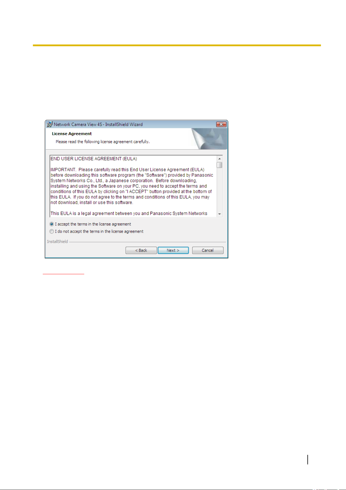
Viewer software
It is necessary to install the viewer software “Network Camera View 4S” to display images on a PC. This
software can be installed directly from the camera or by selecting the [Install] button next to [Viewer
Software] on the menu of the CD-ROM provided, and then following the on-screen instructions.
Preface
IMPORTANT
• The default setting of “Automatic installation of viewer software” is “On”. Follow the instructions on
page 178 when the message is displayed on the information bar of the browser.
• When the “Live” page is displayed for the first time, the install wizard of the ActiveX
to display images from the camera will be displayed. Follow the instructions of the wizard.
• When the install wizard is displayed again even after completing the installation of the ActiveX, restart
the PC.
• The viewer software used on each PC should be licensed individually. The number of installations of
the viewer software from the camera can be checked on the [Upgrade] tab of the “Maintenance” page
(®page 154). Refer to your dealer for the software licensing.
®
control required
Operating Instructions 3
Page 4

Table of Contents
Table of Contents
1 Monitor images on a PC ..........................................................................7
1.1 Monitor images from a single camera .............................................................................7
1.2 About the “Live” page (BL-VT164W/BL-VT164) ...........................................................10
1.3 About the “Live” page (BL-VP104W/BL-VP104/BL-VP101) .........................................15
1.4 Monitor images from multiple cameras ........................................................................18
2 Monitor images on a cellular phone/mobile terminal .........................19
2.1 Monitor images on a cellular phone ..............................................................................19
2.2 Monitor images on a mobile terminal ............................................................................22
3 Action at an alarm occurrence ..............................................................30
3.1 Alarm type ........................................................................................................................30
3.2 Action at an alarm occurrence .......................................................................................30
4 Transmit images onto an FTP server ...................................................32
4.1 Transmit an alarm image at an alarm occurrence (Alarm image
transmission) ...................................................................................................................32
4.2 Transmit images at a designated interval or period (FTP periodic image
transmission) ...................................................................................................................32
5 About the network security ...................................................................33
5.1 Equipped security functions ..........................................................................................33
6 Display the setup menu from a PC .......................................................34
6.1 How to display the setup menu .....................................................................................34
6.2 How to operate the setup menu .....................................................................................35
6.3 About the setup menu window ......................................................................................37
7 Configure the basic settings of the camera [Basic] ...........................39
8 Configure the Internet settings [Internet] ............................................44
9 Configure the settings relating to images and audio [Image/Audio]
(BL-VT164W/BL-VT164)/ Configure the settings relating to images
[Image] (BL-VP104W/BL-VP104/BL-VP101) .........................................46
9.1 Configure the settings relating to the aspect ratio [JPEG/H.264] ..............................46
9.2 Configure the settings relating to JPEG images [JPEG/H.264] ..................................47
9.3 Configure the settings relating to H.264 images [JPEG/H.264] ..................................49
9.4 Configure the settings relating to the camera operations [Cam. Function]
(BL-VT164W/BL-VT164) ..................................................................................................55
9.5 Configure the settings relating to images and the preset positions [Image/Position]
(BL-VT164W/BL-VT164)/ Configure the settings relating to image adjust, extra zoom,
and privacy zone [Image/Privacy] (BL-VP104W/BL-VP104/BL-VP101) ......................57
9.5.1 Configure the settings relating to image quality (“Image adjust” setup menu) ...............58
9.5.2 Set mask areas ..............................................................................................................62
9.5.3 Configure the settings relating to the preset positions (“Preset position” setup menu)
(BL-VT164W/BL-VT164) ................................................................................................65
9.5.3.1 Register the preset positions .......................................................................................66
9.5.4 Adjust the angular field of view using the extra zoom function (BL-VP104W/
BL-VP104) ......................................................................................................................68
9.5.5 Configure the settings relating to the privacy zone (“Privacy zone” setup menu)
(BL-VT164W/BL-VT164) ................................................................................................68
4 Operating Instructions
Page 5

Table of Contents
9.5.6 Configure the settings relating to the privacy zone (“Privacy zone” setup menu)
(BL-VP104W/BL-VP104/BL-VP101) ..............................................................................70
9.6 Configure the settings relating to audio [Audio] (BL-VT164W/BL-VT164) ................72
10 Configure the multi-screen settings [Multi-screen] ............................75
11 Configure the alarm settings [Alarm] ...................................................77
11.1 Configure the settings relating to the alarm action [Alarm] .......................................77
11.2 Configure the settings relating to the camera action on alarm occurrence [Alarm]
(BL-VT164W/BL-VT164) ..................................................................................................79
11.3 Configure the settings relating to the alarm image [Alarm] ........................................80
11.4 Configure the settings relating to the alarm output terminal [Alarm] (BL-VT164W/
BL-VT164) ........................................................................................................................82
11.5 Change the AUX name [Alarm] (BL-VT164W/BL-VT164) .............................................83
11.6 Configure the VMD settings [VMD area] .......................................................................84
11.7 Configuration of the settings relating to the E-mail notification [Notification] .........87
11.8 Configure the settings relating to Panasonic alarm protocol [Notification] .............88
12 Configure the setting relating to the image recognition [Advanced
func.] .......................................................................................................91
12.1 Configure the settings relating to the XML notification [XML notification] ...............91
12.2 Configuration of the settings relating to the face detection [Face detection] ..........93
13 Configure the settings relating to the authentication [User
mng.] .......................................................................................................94
13.1 Configure the settings relating to the user authentication [User auth.] ....................94
13.2 Configure the settings relating to the host authentication [Host auth.] ....................95
13.3 Configure the settings relating to the priority stream [System] .................................96
14 Configure the settings of the servers [Server] ....................................99
14.1 Configure the settings relating to the E-mail server [E-mail] .....................................99
14.2 Configure the settings relating to the FTP server [FTP] ...........................................100
14.3 Configure the settings relating to the NTP server [NTP] ...........................................101
15 Configuring the network settings [Network] .....................................104
15.1 Configure the network settings [Network] ..................................................................104
15.2 Configure the HTTPS settings .....................................................................................112
15.2.1 Generation of the CRT key (SSL encryption key) ........................................................113
15.2.2 Generation of the self-signed certificate (security certificate) .......................................114
15.2.3 Generation of CSR (Certificate Signing Request) ........................................................116
15.2.4 Installation of the server certificate ...............................................................................117
15.2.5 Configuration of the connection protocol ......................................................................118
15.3 Access the camera using the HTTPS protocol ..........................................................119
15.3.1 Install the security certificate ........................................................................................119
15.4 Configure the settings relating to DDNS [DDNS] .......................................................129
15.4.1 Configuration of the DDNS service (Example of the “Viewnetcam.com” service) ........130
15.4.2 When using the “Viewnetcam.com” service .................................................................131
15.4.3 Procedure to register information for the “Viewnetcam.com” service ...........................132
15.4.4 Checking the information registered for the “Viewnetcam.com” service ......................133
15.4.5 When using “Dynamic DNS Update” ............................................................................133
15.4.6 When using “Dynamic DNS Update(DHCP)” ...............................................................134
15.5 Configure the settings relating to SNMP [SNMP] ......................................................134
15.6 Configure the settings relating to the FTP periodic image transmission [FTP img.
trans.] .............................................................................................................................135
Operating Instructions 5
Page 6

Table of Contents
15.7 Configure the schedule settings of the FTP periodic image transmission [FTP img.
trans.] .............................................................................................................................137
15.7.1 How to set the schedules .............................................................................................137
15.7.2 How to delete the set schedule ....................................................................................138
16 Use the camera on a wireless LAN [Wireless] (BL-VT164W/
BL-VP104W) ..........................................................................................140
16.1 Manually connecting the camera to a wireless LAN (manual settings)
[Basic] ............................................................................................................................140
16.2 Connecting the camera to a wireless LAN with WPS (automatic settings)
[Basic] ............................................................................................................................144
16.3 Using the camera's Wireless QoS [Basic] ..................................................................148
16.4 Confirming the camera's wireless information [Status] ............................................148
17 Configure the settings relating to the schedules [Schedule] ..........151
18 Maintenance of the camera [Maintenance] ........................................154
18.1 Check the system log [System log] .............................................................................154
18.2 Upgrade the firmware [Upgrade] .................................................................................154
18.3 Check the status [Status] .............................................................................................156
18.4 Reset the settings/Reboot the camera [Default reset] ...............................................157
19 Privacy Mode (BL-VT164W/BL-VT164) ...............................................159
19.1 Configuring the Privacy Mode with the PRIVACY button .........................................159
19.2 Configuring the Privacy Mode with the setup menu .................................................160
19.3 Turning the Privacy Mode off .......................................................................................160
20 Using the CD-ROM ...............................................................................161
20.1 About the CD launcher .................................................................................................161
20.2 Installing Panasonic “IP Setting Software” ................................................................162
20.3 Installing the manuals ..................................................................................................163
20.4 Installing the Viewer software ......................................................................................163
20.5 Configure the network settings of the camera using the Panasonic “IP Setting
Software” .......................................................................................................................164
21 About the displayed system log .........................................................166
22 Troubleshooting ...................................................................................170
6 Operating Instructions
Page 7
1 Monitor images on a PC
1 Monitor images on a PC
The following are descriptions of how to monitor images from the camera on a PC.
1.1 Monitor images from a single camera
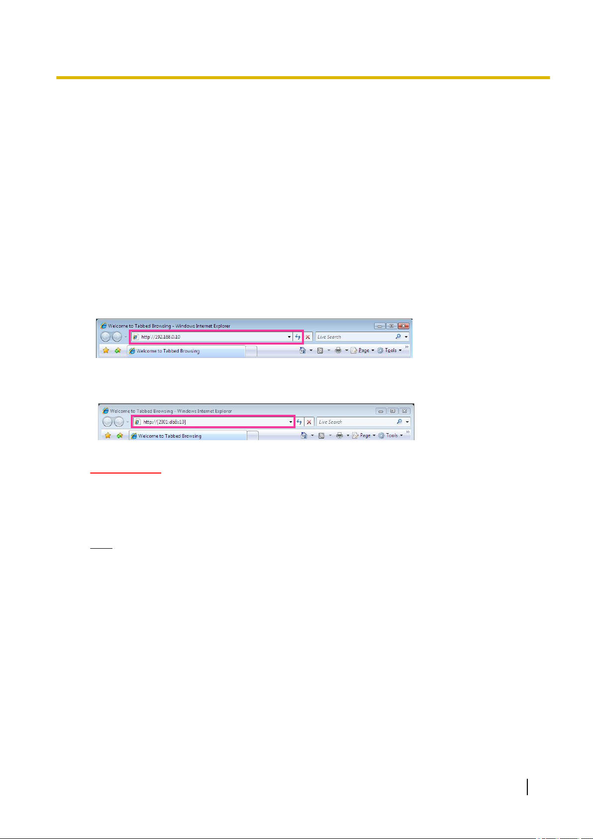
1. Start up the web browser.
2. Enter the IP address designated using the Panasonic “IP Setting Software” in the address box of the
browser.
• Example when entering an IPv4 address: http://URL registered using IPv4 address
http://192.168.0.10/
• Example when entering an IPv6 address: http://[URL registered using IPv6 address]
http://[2001:db8::10]/
<Example of IPv4 access>
<Example of IPv6 access>
IMPORTANT
• When the HTTP port number is changed from “80”, enter “http://IP address of the camera + : (colon)
+ port number” in the address box of the browser. (Example: http://192.168.0.11:8080)
• When the PC is in a local network, configure the proxy server setting of the web browser (under
[Internet Options...] under [Tools] of the menu bar) to bypass the proxy server for the local address.
Note
• Refer to page 119 for further information about the case in which “HTTPS” is selected for
“HTTPS” - “Connection” on the [Network] tab of the “Network” page (®page 104).
Operating Instructions 7
Page 8
1 Monitor images on a PC
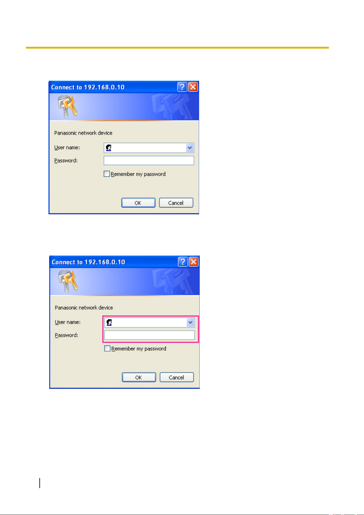
3. Press the [Enter] key on the keyboard.
→ The window with the user name and password entry fields will be displayed.
4. Enter the user name and the password.
The default user name and password are as follows.
User name: admin
Password: 12345
8 Operating Instructions
Page 9
5. Click the [OK] button.
VT164W
VT164W
VT164
VT164
VP104W
VP104W
VP104
VP104
VP101
VP101
→ The “Live” page will be displayed. Refer to
: page 15 for further information about the “Live” page.
1 Monitor images on a PC
: page 10,
When “Off” is selected for “User auth.”, the authentication window will not be displayed before displaying
live images. However, when the [Setup] button is clicked, an authentication window is displayed. A user
name and password must be entered.
The default user name and password are as follows.
User name: admin
Password: 12345
IMPORTANT
• To enhance the security, change the password for the user name “admin”. It is recommended to change
this password periodically.
• When displaying multiple H.264 images on a PC, images may not be displayed depending on the
performance of the PC.
Note
• The maximum number of concurrent access user is 14 including users who is receiving H.264 images
and users who are receiving JPEG images. Depending on the set values for “Bandwidth control(bit
rate)” and “Max bit rate (per client)*”, the maximum concurrent access number may be 14 or less users.
When 14 users are concurrently accessing, the access limit message will be displayed for users who
subsequently attempt to access. When “Multicast” is selected for “Transmission type” of “H.264”, only
the first user who accessed to monitor H.264 images will be included in the maximum number. The
second and subsequent users who are monitoring H.264 images will not be included in the maximum
number.
• Regardless of whether “On” or “Off” is selected for “H.264 transmission”, the first images displayed are
JPEG images.
• The refresh interval may become longer depending on a network environment, PC performance,
photographic subject, access traffic, etc.
<Refresh interval of JPEG images>
When “H.264 transmission” is operating: max. 5 fps
When “H.264 transmission” is not operating (or stopped): max. 30 fps
Operating Instructions 9
Page 10
KL
A
C
D
E
F
H
I
G
B
OQR
S
T
U
P
J
M
N
1 Monitor images on a PC
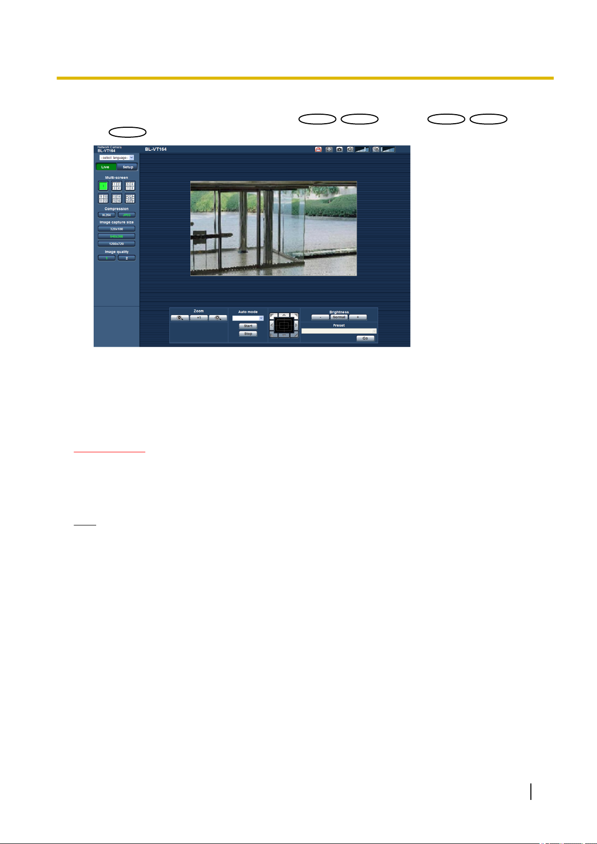
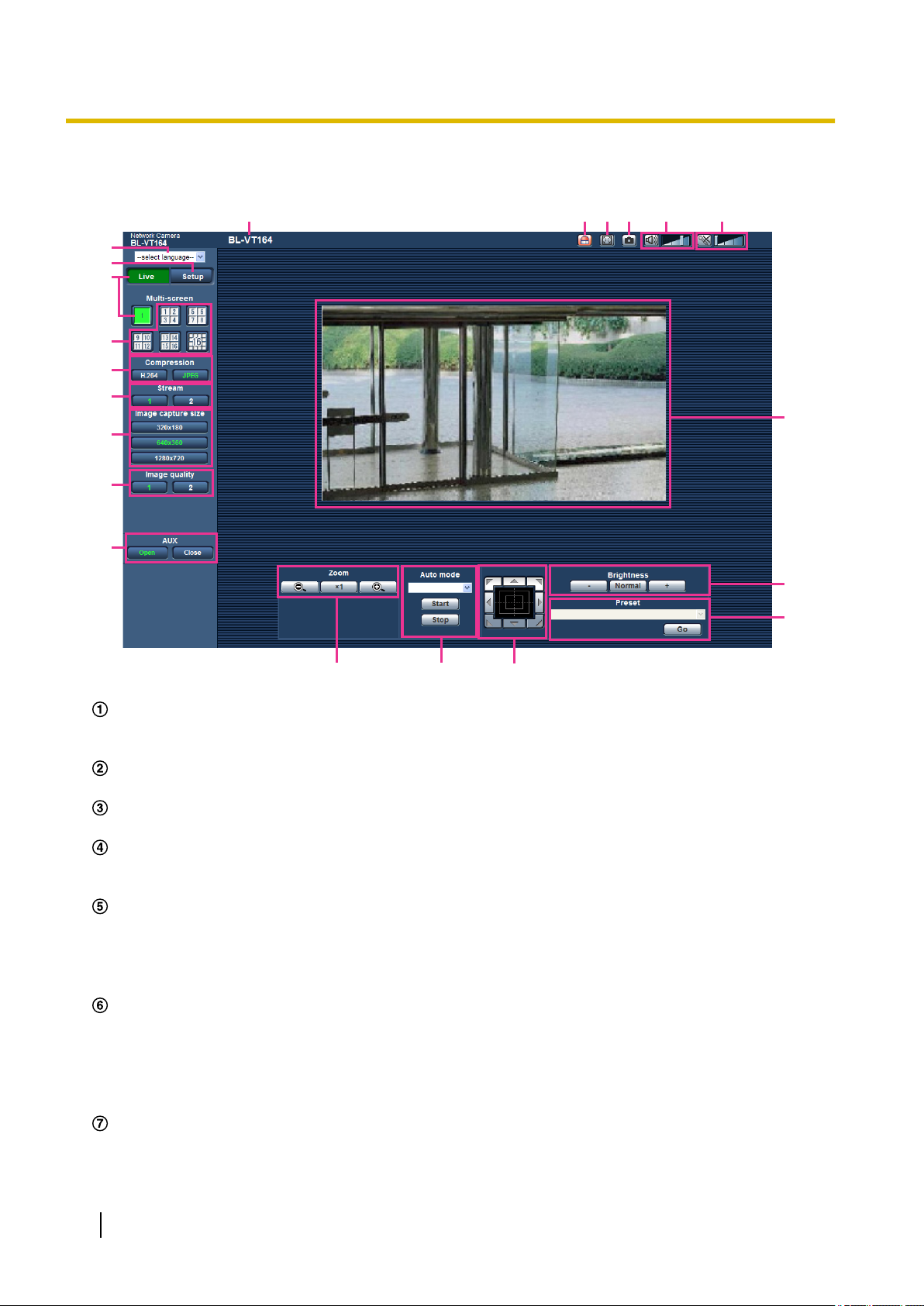
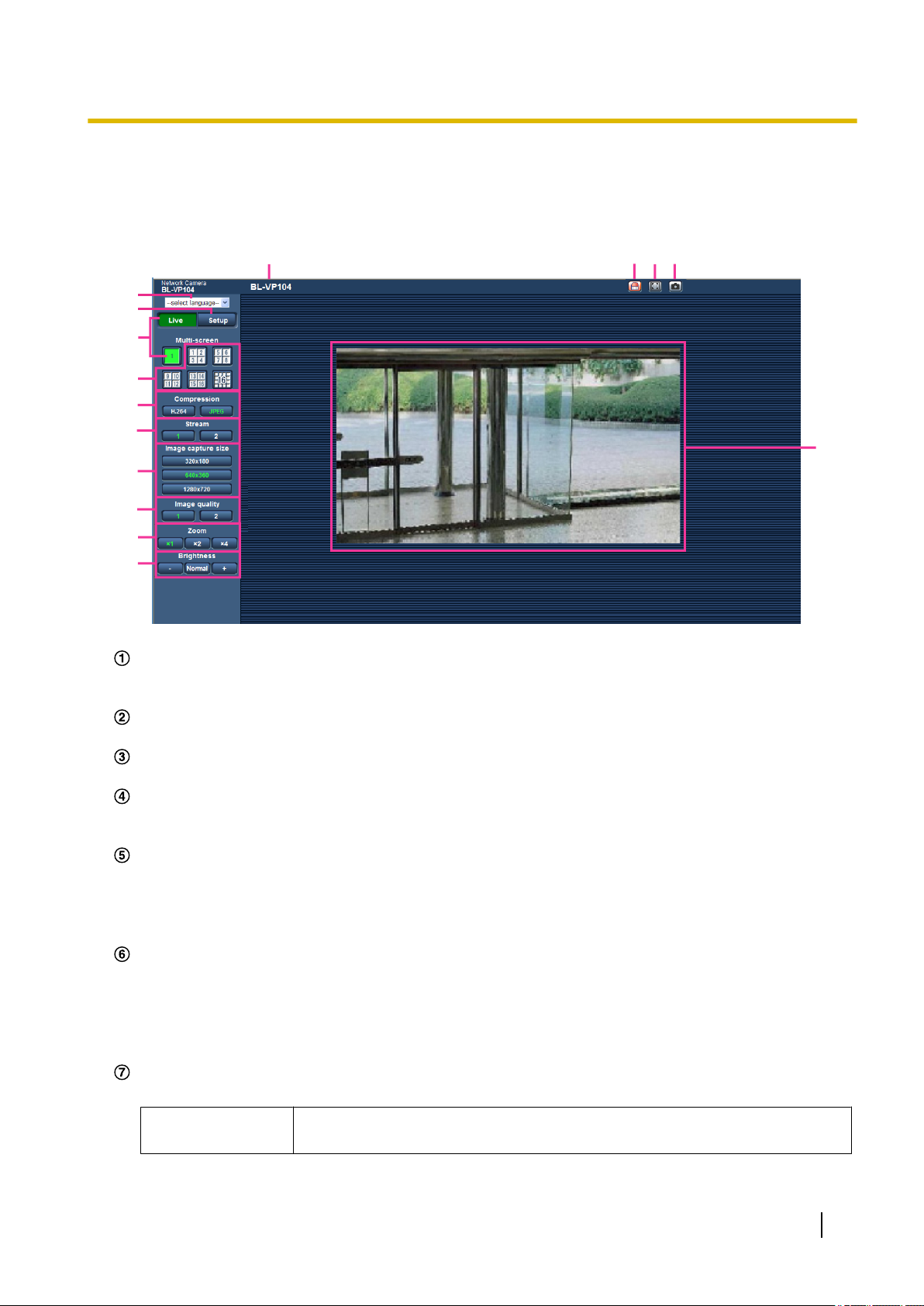
1.2 About the “Live” page (BL-VT164W/BL-VT164)
[select language] pull-down menu
The camera’s display language can be selected. The default language can be set in the [Language] in the
[Basic] settings. (®page 39)
[Setup] button
*1
Displays the setup menu. The button will turn green and the setup menu will be displayed.
[Live] button
Display the “Live” page. The button will turn green and the “Live” page will be displayed.
[Multi-screen] buttons
Images from multiple cameras can be displayed on a multi-screen by registering cameras on the setup
menu. (®page 18)
[Compression] buttons
• [H.264] button: The letters “H.264” on the button will turn green and an H.264 image will be displayed.
When “On” is selected for “H.264 transmission” of “H.264(1)”, “H.264(2)”, the [H.264] button will be
displayed. (®page 51)
• [JPEG] button: The letters “JPEG” on the button will turn green and JPEG image will be displayed.
[Stream] buttons
These buttons will be displayed only when an H.264 image is displayed.
• [1] button: The letter “1” will turn green and images in the main area will be displayed in accordance
with the setting of “H.264(1)”. (®page 51)
• [2] button: The letter “2” will turn green and images in the main area will be displayed in accordance
with the setting of “H.264(2)”. (®page 51)
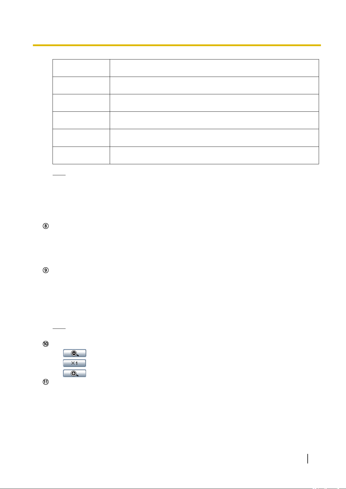
[Image capture size] buttons
These buttons will be displayed only when a JPEG image is displayed.
10 Operating Instructions
Page 11
1 Monitor images on a PC
[VGA] The letters “VGA” will turn green and images in the main area will be displayed
in VGA size.
[QVGA] The letters “QVGA” will turn green and images in the main area will be displayed
in QVGA size.
[640x360] The letters “640x360” will turn green and images in the main area will be
displayed in 640 x 360 (pixels).
[320x180] The letters “320x180” will turn green and images in the main area will be
displayed in 320 x 180 (pixels).
[800x600] The letters “800x600” will turn green and images in the main area will be
displayed in 800 x 600 (pixels).
[1280x720] The letters “1280x720” will turn green and images in the main area will be
displayed in 1280 x 720 (pixels).
Note
• When “1280x720” is selected for the image capture size, it may become smaller than the actual
size depending on the window size of the web browser.
• The buttons [VGA], [QVGA] and [800x600] are displayed only when “4:3” is selected for “Aspect
ratio”.
• The buttons [640x360], [320x180], and [1280x720] are displayed only when “16:9” is selected for
“Aspect ratio”.
[Image quality] buttons
These buttons will be displayed only when a JPEG image is displayed.
• [1] button: Images in the main area will be displayed in accordance with the setting for “Quality1” of
“Image quality setting”. (®page 47)
• [2] button: Images in the main area will be displayed in accordance with the setting for “Quality2” of
“Image quality setting”. (®page 47)
[AUX] buttons
These buttons will be displayed only when “AUX output” is selected for “Terminal 3” of “Alarm” on the setup
menu. (®page 77)
*2
• [Open] button: The letters “Open” on the button will turn green and the status of AUX connector will
be open.
• [Close] button: The letters “Close” on the button will turn green and the status of the AUX connector
will be closed.
Note
• The names of “AUX”, “Open” and “Close” can be changed. (®page 83)
[Zoom] buttons
*2
• : Click this button to adjust the zoom ratio to the “Wide” side.
• : Click this button to set the zoom ratio to x1.0.
• : Click this button to adjust the zoom ratio to the “Tele” side.
[Auto mode]
Select an operation from the pull-down menu and click the [Start] button. The selected operation will start.
Click the [Stop] button to stop the operation.
The selected operation will stop when the camera (panning/tilting/zooming) is operated or when an action
that is to be taken according to the settings for “Self return” (®page 55) or for “Camera action on
alarm” (®page 79) starts.
*2
Operating Instructions 11
Page 12
1 Monitor images on a PC
• Preset map-shot: Eight thumbnail images of the preset position 1-8 (®page 65) will be displayed
orderly on a newly displayed window. When a thumbnail image is clicked, the camera moves to the
respective position and live images will be displayed on the “Live” page.
Note
• Do not operate the browser until all the thumbnail images are displayed and the camera returns to
the original position (where the camera was when “360 map-shot” or “Preset map-shot” was carried
out).
• When “Preset map-shot” is carried out with an unregistered preset position (among preset position
1-8), the thumbnail image of the preset position before the unregistered preset position will be
displayed.
In this case, the camera will not move when the thumbnail image is clicked.
• The camera will not always return to the exactly same position where it was before “Preset
map-shot” was carried out. (It may sometimes be slightly different.)
• The window on which the thumbnail images are displayed will close when clicking the following
buttons that can switch the camera channel or reload images: [Live], [Multi-screen], [H.264],
[JPEG], [Stream], [Image capture size], [Image quality], [Setup].
To display the thumbnail images again, carry out “Preset map-shot” again.
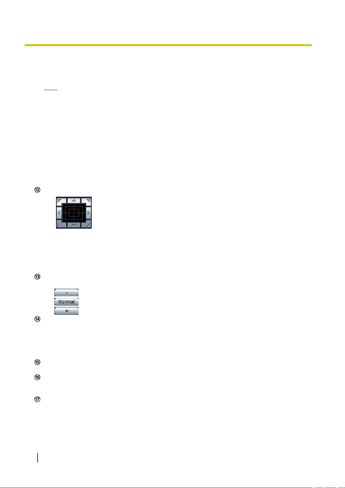
Control pad/buttons
*2
• : Left-click on the control pad to adjust the horizontal/vertical position of the camera
(panning/tilting). Panning/tilting speed will be faster if a clicked point gets farther from the center point
of the control pad.
It is also possible to pan/tilt the camera by dragging the mouse.
Zoom can be adjusted by right-clicking. When an upper/lower area of the control pad is right-clicked,
the displayed image will be zoomed in/out on.
Zoom can also be adjusted using the mouse wheel.
[Brightness] buttons
*2
Available range: 0 - 127
•
button: The displayed image will be darker.
• button: The adjusted brightness will return to the default brightness (64).
• button: Image will be brighter.
[Preset]
Select a preset position from the pull-down menu and click the [Go] button. The camera will move to the
selected preset position (®page 65). “H” next to the preset position number indicates the home position.
When “Home position” is selected, the camera will move to the home position. (®page 55) When “Preset
ID” is registered for a preset position, the registered preset ID will be displayed next to the preset position
number.
Camera title
The camera title entered for “Camera title” on the [Basic] page will be displayed. (®page 39)
Alarm occurrence indication button
This button will be displayed and will blink when an alarm has occurred. When this button is clicked, the
alarm output terminal will be reset and this button will disappear. (®page 30)
Full screen button
Images will be displayed on a full screen. To return to the “Live” page, press the [Esc] key. The aspect ratio
of displayed images will be adjusted in accordance with the monitor.
*2
*2
12 Operating Instructions
Page 13

1 Monitor images on a PC
Snap shot button
Click this button to take a picture (a still picture). The picture will be displayed on a newly opened window.
When right-clicking on the displayed image, the pop-up menu will be displayed. It is possible to save the
image on the PC by selecting “Save” from the displayed pop-up menu.
When “Print” is selected, printer output is enabled.
Note
• The following setting may be necessary when using Windows 7 or Windows Vista.
Click “Internet Options” on the Tools menu of Internet Explorer, and then click the [Security] tab.
Select “Trusted Sites”, and click “Sites”. Register the camera address on the “Website” in the
“Trusted Sites” window.
Mic input button
Turns on/off the audio reception (hear audio from the camera on a PC). This button will be displayed only
when “Mic input”, “Interactive(Full-duplex)” or “Interactive(Half-duplex)” is selected for “Audio transmission/
reception” on the setup menu. (®page 72)
When this button is clicked, the button will turn into the button and audio from the camera will not be
heard.
Audio volume can be adjusted (Low/ Middle/ High) by moving the volume cursor .
Audio output button
Turns on/off the audio transmission (play audio from the PC on the unit speaker). This button will be
displayed only when “Audio output”, “Interactive(Full-duplex)” or “Interactive(Half-duplex)” is selected for
“Audio transmission/reception” on the setup menu. (®page 72)
The button will blink during the audio transmission.
When this button is clicked, the button will turn into the
*3
*3
button and audio from the PC will not be heard.
Audio output volume can be adjusted (Low/Middle/High) by moving the volume cursor .
Note
• When a user is using the audio transmission function with “Interactive(Half-duplex)” selected, the
receiver button and the transmission button will be inoperable for the other users. When
“Interactive(Full-duplex)” is selected, the transmission button is inoperable for other users.
• Possible duration of audio transmission is up to 5 minutes per transmission. When 5 minutes have
passed, the audio transmission will automatically stop. To turn the audio transmission function on,
click the [Audio output] button again.
• When the camera is restarted, the adjusted volume level (for both the audio transmission and
reception) will return to the level that had been set on the [Audio] tab on the setup menu.
(®page 72)
• Actual volume level will change in three steps even though the volume cursor can be adjusted
minutely.
Main area
Images from the camera will be displayed in this area.
The current time and date will be displayed according to the settings configured for “Time display format”
and “Date/time display format”. (®page 40)
In addition, when being adjusted, the status of brightness (®page 41), panning/tilting degree and the
zoom ratio display (®page 56), and the preset ID (®page 67) will be displayed as well as the characters
configured for “Camera title on screen” (®page 40). The number of lines for the display is 2.
Click a desired point in the main area on the “Live” page that is to be the center of the angle of view. The
camera moves to adjust the position in order to set the clicked point as the center.
When selecting an area in the main area by dragging the mouse, the selected area will be located at the
center of the main area. In this case, the zoom ratio will be adjusted automatically.
Zoom can be adjusted using the mouse wheel.
*2
Operating Instructions 13
Page 14

1 Monitor images on a PC
Note
• When operated by a lower access level user, images displayed on the screen may be changed
temporarily. This does not affect operation of the camera.
• When the mouse is dragged to move the camera beyond its operable range, the camera will move to
the requested direction and will stop at the end of the operable range. Then, the zoom ratio of the
displayed image will automatically be adjusted.
• Depending on the PC in use, screen tearing* may occur when the shooting scene drastically changes
due to the GDI restrictions of the OS.
*A phenomenon in which portions of the screen are displayed out of alignment.
*1
Only operable by users whose access level is “1. Administrator”.
*2
Only operable by users whose access level is “1. Administrator” or “2. Camera control” when “On” is selected for “User auth.”
(®page 94)
*3
Operable by users who belong to the access level selected for “Permission level of audio trans./recep.” on the [Audio] tab of the
“Image/Audio” page. Refer to page 72 for further information about the “Permission level of audio trans./recep.”.
14 Operating Instructions
Page 15
B
A
C
D
E
G
H
I
J
F
KLNM
O
1 Monitor images on a PC
1.3 About the “Live” page (BL-VP104W/BL-VP104/
BL-VP101)
[select language] pull-down menu
The camera’s display language can be selected. The default language can be set in the [Language] in the
[Basic] settings. (®page 39)
[Setup] button
*1
Displays the setup menu. The button will turn green and the setup menu will be displayed.
[Live] button
Display the “Live” page. The button will turn green and the “Live” page will be displayed.
[Multi-screen] buttons
Images from multiple cameras can be displayed on a multi-screen by registering cameras on the setup
menu. (®page 18)
[Compression] buttons
• [H.264] button: The letters “H.264” on the button will turn green and an H.264 image will be displayed.
When “On” is selected for “H.264 transmission” of “H.264(1)”, “H.264(2)”, the [H.264] button will be
displayed. (®page 51)
• [JPEG] button: The letters “JPEG” on the button will turn green and JPEG image will be displayed.
[Stream] buttons
These buttons will be displayed only when an H.264 image is displayed.
• [1] button: The letter “1” will turn green and images in the main area will be displayed in accordance
with the setting of “H.264(1)”. (®page 51)
• [2] button: The letter “2” will turn green and images in the main area will be displayed in accordance
with the setting of “H.264(2)”. (®page 51)
[Image capture size] buttons
These buttons will be displayed only when a JPEG image is displayed.
[VGA] The letters “VGA” will turn green and images in the main area will be displayed
in VGA size.
Operating Instructions 15
Page 16

VP104W
VP104W
VP104
VP104
VP104W
VP104W
VP104
VP104
VP104W
VP104W
VP104
VP104
1 Monitor images on a PC
[QVGA] The letters “QVGA” will turn green and images in the main area will be displayed
[640x360] The letters “640x360” will turn green and images in the main area will be
[320x180] The letters “320x180” will turn green and images in the main area will be
in QVGA size.
displayed in 640 x 360 (pixels).
displayed in 320 x 180 (pixels).
[800x600]
[1280x720]
The letters “800x600” will turn green and images in the main area will be
displayed in 800 x 600 (pixels).
The letters “1280x720” will turn green and images in the main area will be
displayed in 1280 x 720 (pixels).
Note
• The buttons [VGA], [QVGA] and [800x600] are displayed only when “4:3” is selected for “Aspect
ratio”.
• The buttons [640x360], [320x180], and [1280x720] are displayed only when “16:9” is selected for
“Aspect ratio”.
:
• When “1280x720” is selected for the image capture size, it may become smaller than the actual
size depending on the window size of the web browser.
[Image quality] buttons
These buttons will be displayed only when a JPEG image is displayed.
• [1] button: Images in the main area will be displayed in accordance with the setting for “Quality1” of
“Image quality setting”. (®page 47)
• [2] button: Images in the main area will be displayed in accordance with the setting for “Quality2” of
“Image quality setting”. (®page 47)
[Zoom] buttons
Images will be zoomed in on with the electronic zoom by the viewer software “Network Camera View
4S”.
• [x1] button: The letter “x1” will turn green and images in the main area will be displayed at x1.
• [x2] button: The letter “x2” will turn green and images in the main area will be displayed at x2.
• [x4] button: The letter “x4” will turn green and images in the main area will be displayed at x4.
[Brightness] buttons
Available range: 0 - 127
•
button: The displayed image will be darker.
*2
• button: The adjusted brightness will return to the default brightness (64).
• button: Image will be brighter.
Camera title
The camera title entered for “Camera title” on the [Basic] page will be displayed. (®page 39)
Alarm occurrence indication button
This button will be displayed and will blink when an alarm has occurred. When this button is clicked, the
alarm output terminal will be reset and this button will disappear. (®page 30)
Full screen button
Images will be displayed on a full screen. To return to the “Live” page, press the [Esc] key. The aspect ratio
of displayed images will be adjusted in accordance with the monitor.
Snap shot button
Click this button to take a picture (a still picture). The picture will be displayed on a newly opened window.
When right-clicking on the displayed image, the pop-up menu will be displayed. It is possible to save the
image on the PC by selecting “Save” from the displayed pop-up menu.
When “Print” is selected, printer output is enabled.
*2
16 Operating Instructions
Page 17

1 Monitor images on a PC
Note
• The following setting may be necessary when using Windows 7 or Windows Vista.
Click “Internet Options” on the Tools menu of Internet Explorer, and then click the [Security] tab.
Select “Trusted Sites”, and click “Sites”. Register the camera address on the “Website” in the
“Trusted Sites” window.
Main area
*2
Images from the camera will be displayed in this area.
The current time and date will be displayed according to the settings configured for “Time display format”
and “Date/time display format”. (®page 40)
In addition, when being adjusted, the status of brightness (®page 41), panning/tilting degree and the
zoom ratio display (®page 56), and the preset ID (®page 67) will be displayed as well as the characters
configured for “Camera title on screen” (®page 40). The number of lines for the display is 2.
Click a desired point in the main area on the “Live” page that is to be the center of the angle of view. The
camera moves to adjust the position in order to set the clicked point as the center.
When selecting an area in the main area by dragging the mouse, the selected area will be located at the
center of the main area. In this case, the zoom ratio will be adjusted automatically.
Zoom can be adjusted using the mouse wheel.
Note
• When operated by a lower access level user, images displayed on the screen may be changed
temporarily. This does not affect operation of the camera.
• When the mouse is dragged to move the camera beyond its operable range, the camera will move to
the requested direction and will stop at the end of the operable range. Then, the zoom ratio of the
displayed image will automatically be adjusted.
• Depending on the PC in use, screen tearing* may occur when the shooting scene drastically changes
due to the GDI restrictions of the OS.
*A phenomenon in which portions of the screen are displayed out of alignment.
*1
Only operable by users whose access level is “1. Administrator”.
*2
Only operable by users whose access level is “1. Administrator” or “2. Camera control” when “On” is selected for “User auth.”
(®page 94)
Operating Instructions 17
Page 18
A
C
B
1 Monitor images on a PC
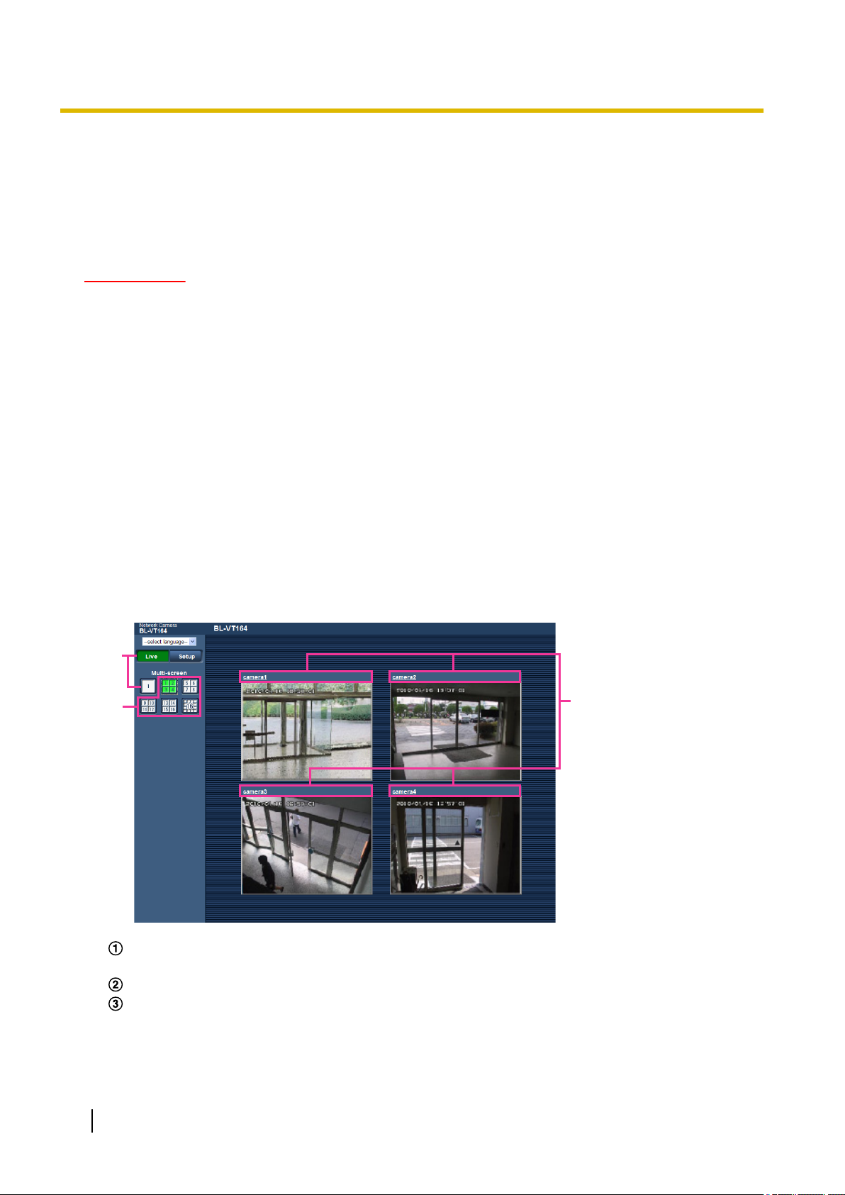
1.4 Monitor images from multiple cameras
Images from multiple cameras can be displayed on a multi-screen. Images from 4 cameras (up to 16 cameras)
can be displayed simultaneously. To display images on a multi-screen, it is necessary to register cameras in
advance. 4 cameras can be registered as a group and up to 4 groups (16 cameras) can be registered.
(®page 75)
IMPORTANT
• When displaying images on a 16-screen, panning, tilting and zooming operations become unavailable
for images from cameras with Pan/Tilt/Zoom functions.
• When displaying images on a 4-screen, panning, tilting and zooming operations become available only
for images from cameras with Pan/Tilt/Zoom functions. Refer to the [Readme] file on the provided
CD-ROM for further information about the compatible cameras and their versions. Or refer to our
website (http://panasonic.net/pss/security/support/info.html).
• Only JPEG images with frame by frame playback can be displayed on a multi-screen. Audio will not
be heard.
• When the power is turned off or the LAN cable is disconnected while displaying images, displaying
images on a multi-screen from the “Live” page will become unavailable.
• When displaying the image on a multi-screen and “16:9” is selected for “Aspect ratio”, the image will
be displayed altered vertically to the aspect ratio of “4:3”.
• “Network Camera Recorder with Viewer Software Lite” which supports live monitoring and recording
images from multiple cameras is available. For further information, refer to our website
(http://panasonic.net/pss/security/support/info.html).
1. Click the desired [Multi-screen] on the “Live” page.
→ Images from the registered cameras will be displayed on a selected multi-screen (screen can be split
up to 16 areas). The following are instructions when displaying on a 4-split screen.
To show 1 camera screen, click the [Live] button.
You can also click “1” below “Multi-screen” to display the camera's “Live” page.
Click the [Multi-screen] button to display images from cameras in a multi-screen of 4 to 16 screens.
Click a camera title. Live images from the camera corresponding to the clicked camera title will be
displayed on the “Live” page of the newly opened window.
18 Operating Instructions
Page 19

2 Monitor images on a cellular phone/mobile terminal
2 Monitor images on a cellular phone/mobile
terminal
2.1 Monitor images on a cellular phone
It is possible to connect to the camera using a cellular phone via the Internet and monitor images (JPEG only)
from the camera on the screen of the cellular phone. It is also possible to refresh images to display the latest
image or perform panning, tilting and zooming operations.
IMPORTANT
• When the authentication window is displayed, enter the user name and password. The default user
name and password are as follows.
User name: admin
Password: 12345
To enhance the security, change the password for the user “admin”. (®page 94)
• If the cellular phone in use is not compatible with UTF-8 encode, it is impossible to display the screen
correctly.
Note
• It is necessary to configure the network settings of the cellular phone in advance to connect to the
Internet and monitor images from the camera. (®page 104)
Operating Instructions 19
Page 20
A
B
C
D
E
F
G
H
I
2 Monitor images on a cellular phone/mobile terminal
1. Access to “http://IP address/mobile”
*1
cellular phone.
→ Images from the camera will be displayed.
or “http://Host name registered in the DDNS server/mobile” using a
20 Operating Instructions
Page 21
J
VT164W
VT164W
VT164
VT164
VT164W
VT164W
VT164
VT164
VT164W
VT164W
VT164
VT164
VT164W
VT164W
VT164
VT164
VT164W
VT164W
VT164
VT164
VT164W
VT164W
VT164
VT164
VT164W
VT164W
VT164
VT164
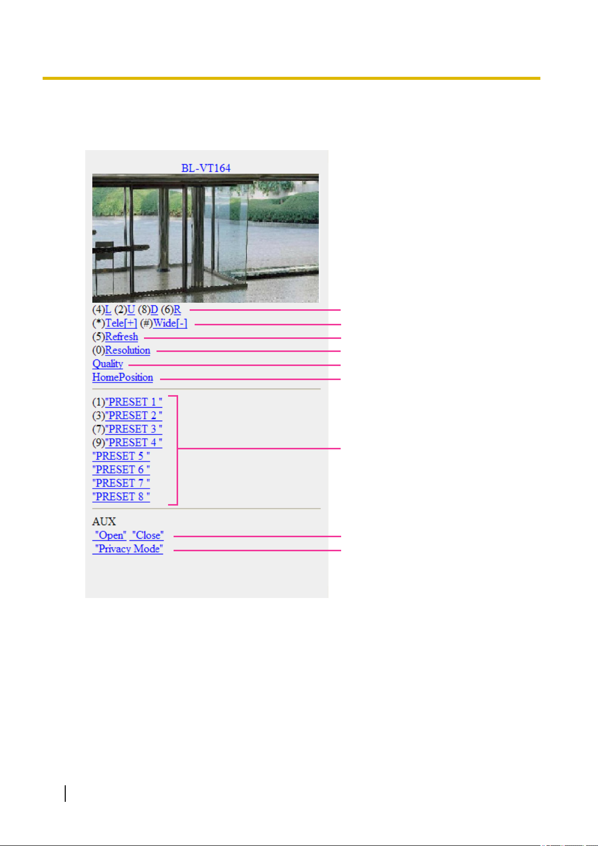
2 Monitor images on a cellular phone/mobile terminal
Functions Outline of functions
A Pan/tilt
B Zooming control
*2
Controls the camera direction. The camera will pan or tilt to each direction
by pressing the corresponding dial key.
*2
It is possible to perform zooming operations of the camera by pressing “*”
or “#”.
C Refresh Refreshes the camera images by pressing the dial key “5”.
D Resolution control Changes the image capture size by pressing the dial key “0”.
• Image in the aspect ratio of “4:3”
Changes the image capture size
between 320x240 (default) and
640x480.
• Image in the aspect ratio of
“16:9”
Changes the image capture size
between 320x180 (default) and
640x360.
Note
• Some cellular phones cannot change the image capture size even
when resolution is changed by resolution control.
E Image quality
control
F Home position
G Preset
*2
H AUX control
*2
*2
It is possible to change the image quality between “Quality1” and
“Quality2”. (®page 47)
The camera will move to the home position (®page 55). Home position
will be displayed only when home position is set.
The camera will move to the designated preset position to display images
by pressing the dial key corresponding to the desired channel. (The dial key
numbers are not displayed for Preset No 5 or greater. Only preset IDs will
be displayed for them.) (®page 65)
Controls the AUX terminal.
These buttons will be displayed only when “AUX output” is selected for
“Terminal 3” on the setup menu. (®page 77)
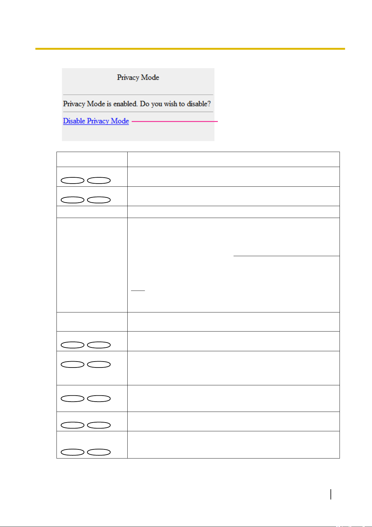
I Privacy Mode
J Disable Privacy
Mode
Select “Privacy Mode” to activate Privacy mode.
Select “Disable Privacy Mode” to return to the normal display.
Operating Instructions 21
Page 22

2 Monitor images on a cellular phone/mobile terminal
Note
• When the HTTP port number is changed from “80”, enter “http://IP address: (colon) + port number/
mobile”*1 in the address box of the browser. When using the DDNS function, access to “http://Host
name registered in the DDNS server: (colon) + port number/mobile”.
• When “HTTPS” is selected for “HTTPS” - “Connection” on the [Network] tab of the “Network” page,
enter as follows.
“https://IP address: (colon) + port number/mobile” or “https://Host name registered in the DDNS server:
(colon) + port number/mobile”
• When the authentication window is displayed, enter the user name of an administrator or user and
password. Depending on the cellular phone in use, password entry may be required each time the
screen is switched.
• It is impossible to transmit/receive audio using a cellular phone.
• Depending on the cellular phone in use, larger size images may not be displayed. In this case, selecting
“9 Low” for “Image quality setting” of “JPEG” (®page 47) may sometimes solve this problem.
• Depending on the cellular phone in use or its contract plan, it may be impossible to access.
*1
IP address is the global WAN IP address of the router that can be accessed via the Internet.
*2
Only displayed for users whose access level is “1. Administrator” or “2. Camera control” when “On” is selected for “User auth.”.
(®page 94)
2.2 Monitor images on a mobile terminal
It is possible to connect to the camera using a mobile terminal and monitor images (MJPEG only) from the
camera on the screen of the mobile terminal. Images are automatically refreshed to display the latest image.
Operations such as pan/tilt/zoom can also be performed.
The compatible mobile terminals are shown as follows. (As of January, 2012)
– iPad, iPhone, iPod touch (iOS 4.2.1 or later)
– Android™ mobile terminals
Only JPEG images can be viewed from standard Android mobile terminal browsers.
For further information about compatible devices, refer to our website
(http://panasonic.net/pss/security/support/info.html).
IMPORTANT
• When the authentication window is displayed, enter the user name and password. The default user
name and password are as follows.
User name: admin
Password: 12345
To enhance the security, change the password for the user “admin”. (®page 94)
Note
• To view the camera images from a mobile terminal, network settings needed in order to connect to the
Internet must be set in advance. (®page 104)
22 Operating Instructions
Page 23
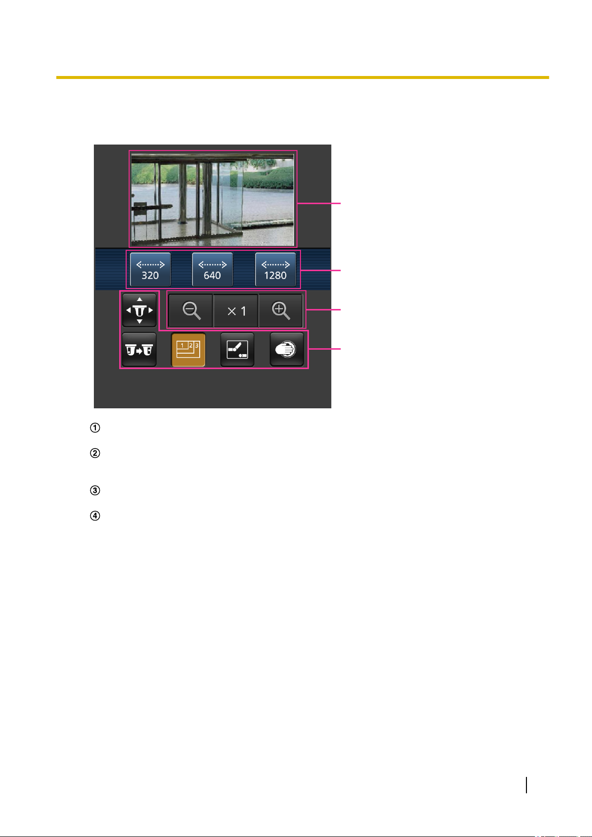
A
B
C
D
2 Monitor images on a cellular phone/mobile terminal
1. Access to “http://IP address/cam”
*1
or “http://Host name registered in the DDNS server/cam”*2 using a
mobile terminal.
→ Images from the camera will be displayed.
Live images area
Displays images from the camera.
Operation buttons area
When functions are selected in the function selection area D, buttons to operate those functions are
displayed.
Zoom operation area
Buttons to operate the zoom are displayed.
Function selection area
When functions that can be operated are selected, operation buttons are displayed in the operation
buttons area B.
Operating Instructions 23
Page 24
CD
A
B E
F
VT164W
VT164W
VT164
VT164
VT164W
VT164W
VT164
VT164
VT164W
VT164W
VT164
VT164
VT164W
VT164W
VT164
VT164
VT164W
VT164W
VT164
VT164
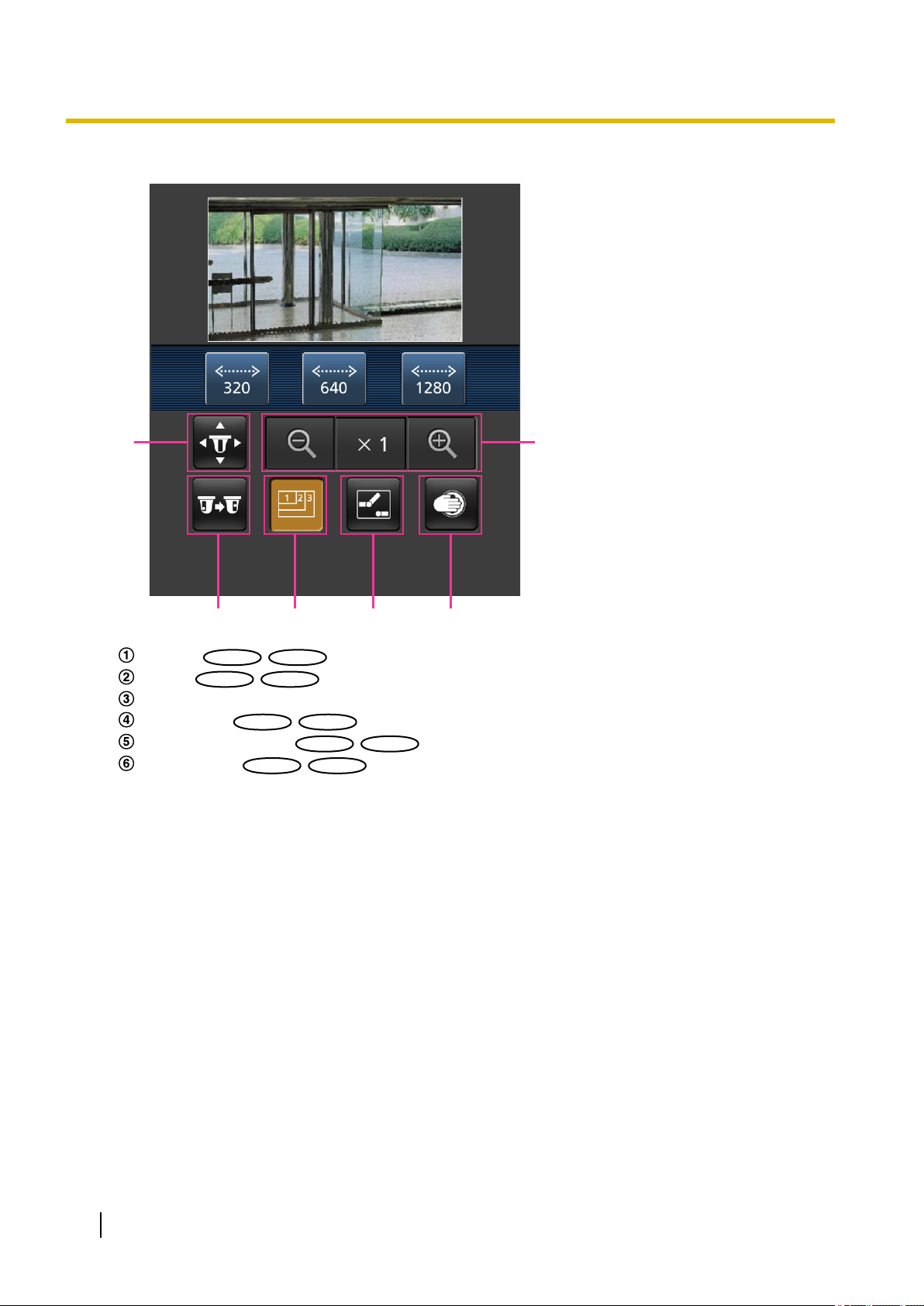
2 Monitor images on a cellular phone/mobile terminal
2. Click the button of the function that you want to operate.
Pan/Tilt
Preset
Resolution control
AUX control
Privacy Mode control
Zoom display
Each function is explained below.
24 Operating Instructions
Page 25
VT164W
VT164W
VT164
VT164
VT164W
VT164W
VT164
VT164
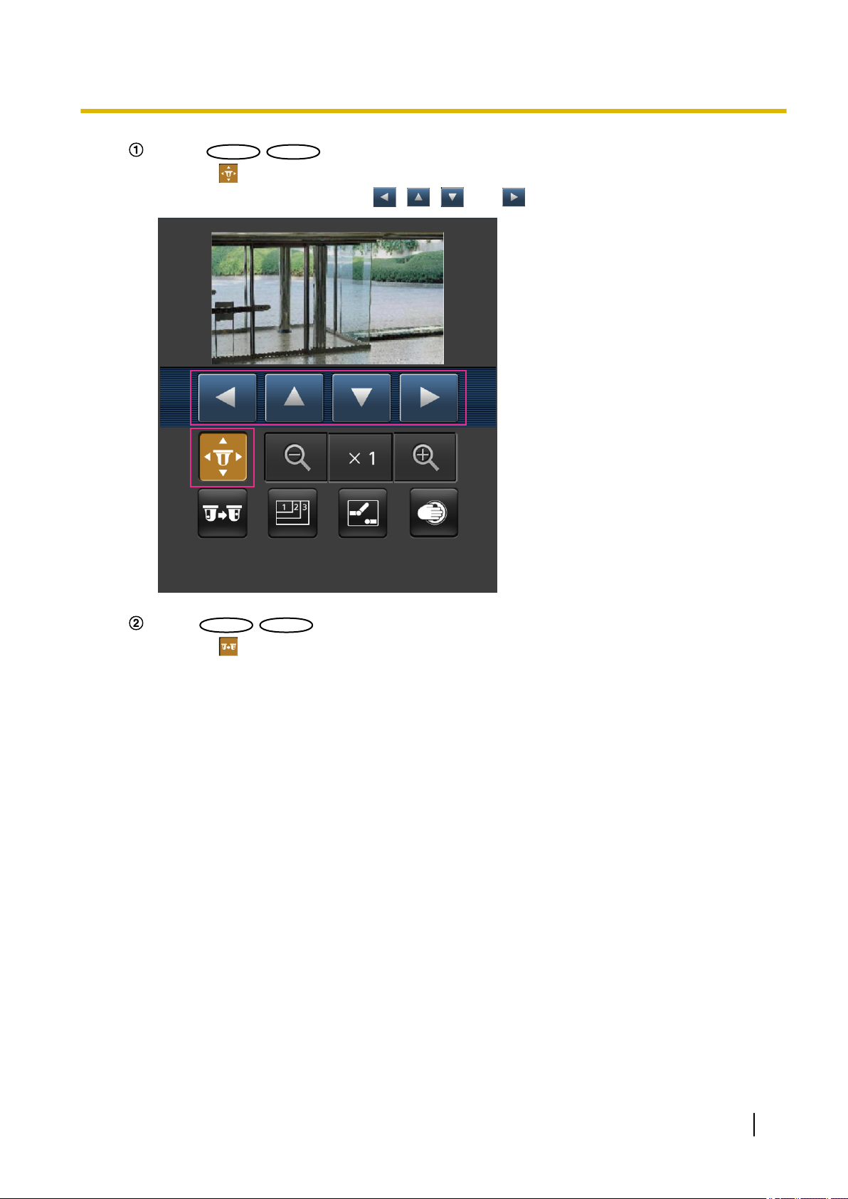
2 Monitor images on a cellular phone/mobile terminal
Pan/Tilt
Press the button to display the buttons used to operate pan/tilt on the screen. The pan/tilt can be
adjusted in each direction with the
, , , and buttons.
Preset
Press the button to display the buttons used to select the preset position on the screen. Camera
images are displayed of the registered preset camera directions according to the preset numbers
selected from the buttons.
• Only position numbers 1-4 for the preset positions are displayed.
• Only registered preset positions are displayed. Unregistered preset positions are not displayed.
Operating Instructions 25
Page 26

VT164W
VT164W
VT164
VT164
VP104W
VP104W
VP104
VP104
VP101
VP101
VT164W
VT164W
VT164
VT164
VP104W
VP104W
VP104
VP104
VP101
VP101
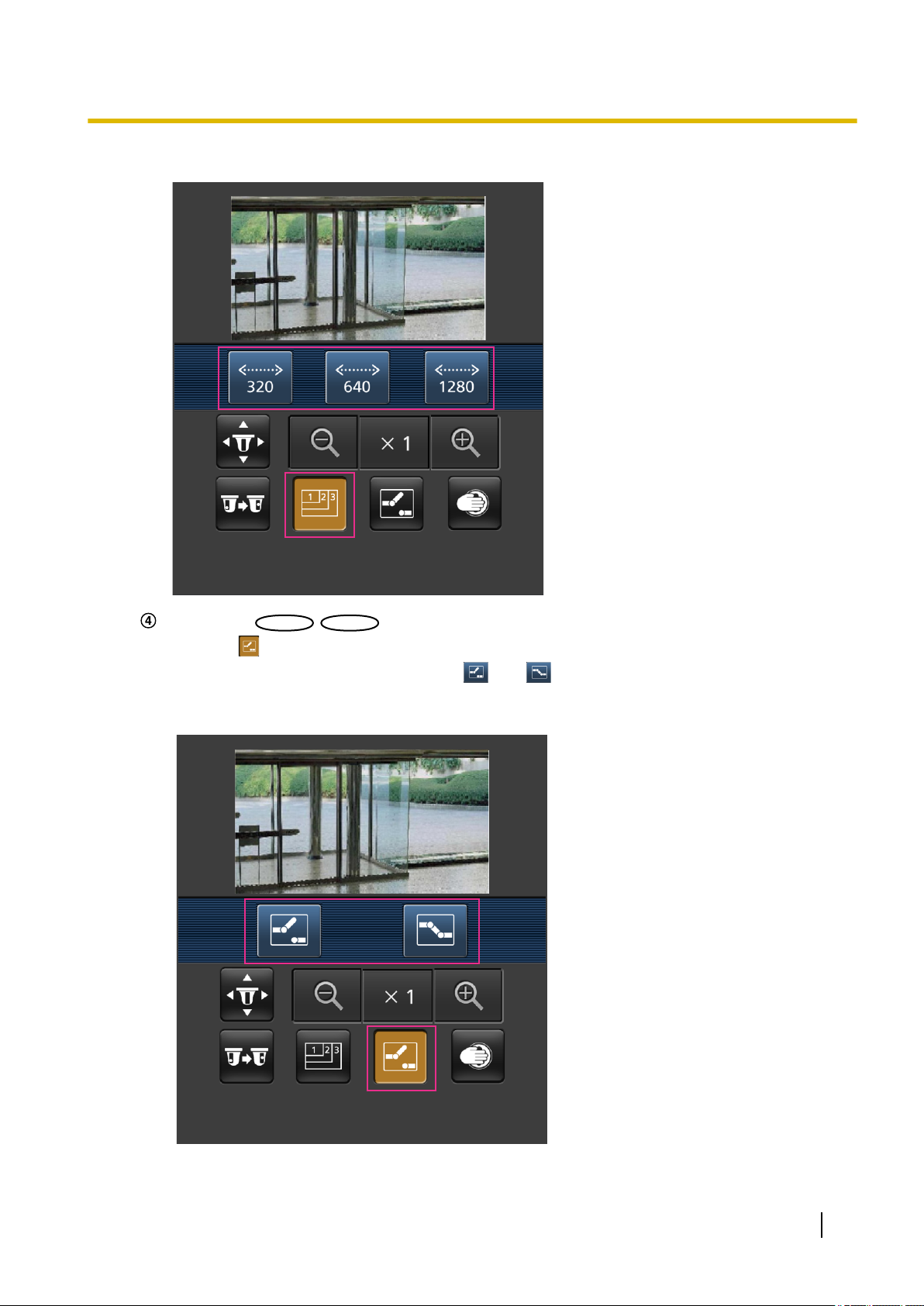
2 Monitor images on a cellular phone/mobile terminal
Resolution control
Press the button to display the buttons used to select the resolution on the screen. The resolution
can be changed by selecting a resolution setting from the buttons.
• Image in the aspect ratio of “4:3”
Changes the image capture size between 320x240, 640x480 (default), and 800x600.
:
Changes the image capture size between 320x240 and 640x480 (default).
:
• Image in the aspect ratio of “16:9”
Changes the image capture size between 320x180, 640x360 (default), and 1280x720.
:
Changes the image capture size between 320x180 and 640x360 (default).
:
26 Operating Instructions
Page 27
VT164W
VT164W
VT164
VT164
2 Monitor images on a cellular phone/mobile terminal
AUX control
Press the button to display the buttons used to operate the AUX output on the screen. The AUX
output terminals can be controlled with the and buttons.
This function is only displayed when [Terminal 3] is set to [AUX output] on the settings menu.
(®page 77)
Operating Instructions 27
Page 28

VT164W
VT164W
VT164
VT164
2 Monitor images on a cellular phone/mobile terminal
Privacy Mode control
Press the button to display the buttons used to operate the privacy mode on the screen. The privacy
mode can be enabled and disabled with the
and buttons.
To activate privacy mode, press .
To deactivate privacy mode, press .
28 Operating Instructions
Page 29

VT164W
VT164W
VT164
VT164
2 Monitor images on a cellular phone/mobile terminal
Zoom display
The camera’s zoom can be operated with the , , and buttons.
Note
• You can change the image size displayed on the mobile terminal by accessing the following addresses.
– Large display: http://IP address/cam/dl
– Medium display: http://IP address/cam/dm
– Small display: http://IP address/cam/ds
• When the resolution is changed by the resolution control, the displayed resolution changes but the
image size remains the same.
• When the HTTP port number is changed from “80”, enter “http://IP address: (colon) + port number/
cam”*1 in the address box of the browser. When using the DDNS function, access to “http://Host name
registered in the DDNS server: (colon) + port number/cam”*2.
• When “HTTPS” is set in “HTTPS” - “Connection” on the [Network] tab of the “Network” page, enter the
following:
“https://IP address: (colon) + port number/cam” or “https://Host name registered in the DDNS server:
(colon) + port number/cam”.
• When the authentication window is displayed, enter the user name of an administrator or user and
password. Depending on the mobile terminal in use, password entry may be required each time the
screen is switched.
• It is impossible to transmit/receive audio using a mobile terminal.
• Depending on the mobile terminal in use, larger size images may not be displayed. In this case,
selecting “9 Low” for “Image quality setting” of “JPEG” (®page 47) may sometimes solve this
problem.
• Depending on the mobile terminal in use or its contract plan, it may be impossible to access.
*1
IP address is the global WAN IP address of the router that can be accessed via the Internet. However, when accessing the same
LAN as the camera with a wireless compatible mobile terminal, the IP address is the local IP address.
*2
Only when accessing the camera through the Internet.
Operating Instructions 29
Page 30

VT164W
VT164W
VT164
VT164
VT164W
VT164W
VT164
VT164
VT164W
VT164W
VT164
VT164
VP104W
VP104W
VP104
VP104
VP101
VP101
3 Action at an alarm occurrence
3 Action at an alarm occurrence
The alarm action (camera action at an alarm occurrence) will be performed when the following alarms occur.
3.1 Alarm type
• Terminal alarm
: When connecting an alarm device such as a sensor to the EXT I/O
connectors 1-3 of the camera, the alarm action will be performed when the connected alarm device is
activated.
• Body heat sensor
: When a temperature difference is detected in the sensor's detection
area, the alarm action will be performed.
• VMD alarm: When motion is detected in the set VMD area, the alarm action will be performed.
*VMD stands for “Video Motion Detection”.
• Command alarm: When a Panasonic alarm protocol is received from the connected device via a network,
the alarm action will be performed.
3.2 Action at an alarm occurrence
Display the alarm occurrence indication button on the “Live” page
The alarm occurrence indication button will be displayed on the “Live” page at an alarm occurrence. (®
IMPORTANT
• When “Polling(30s)” is selected for “Alarm status update mode” (®page 39), the Alarm occurrence
indication button will be refreshed in 30-second intervals. For this reason, it may take a maximum of
30 seconds until the alarm occurrence indication button is displayed on the “Live” page at an alarm
occurrence.
: page 10,
: page 15)
Notify of alarm occurrences to the device connected to the alarm connector
It is possible to output signals from the alarm connector on the rear of the camera and sound the buzzer when
an alarm occurs. The settings for the alarm output can be configured in the “Alarm output terminal setup”
section of the [Alarm] tab of the “Alarm” page. (®page 77, page 82)
Transmit an image onto a server automatically
An alarm image can be transmitted at an alarm occurrence to the server designated in advance. The settings
required to transmit an alarm image to a server can be configured in the “Alarm image” section on the
[Alarm] tab of the “Alarm” page (®page 80) and the [FTP] tab (®page 100) of the “Server” page.
Notify of alarm occurrences by E-mail
Alarm E-mail (alarm occurrence notification) can be sent at an alarm occurrence to the E-mail addresses
registered in advance. Up to 4 addresses can be registered as recipients of the alarm E-mail. An alarm image
(still picture) can be sent with the alarm E-mail as an attached file. The settings for alarm E-mail can be
configured in the “E-mail notification” section on the [Notification] tab of the [Alarm] page (®page 87) and
the [E-mail] tab of the “Server” page (®page 99).
30 Operating Instructions
Page 31

3 Action at an alarm occurrence
Notify of alarm occurrences to the designated IP addresses (Panasonic
alarm protocol notification)
This function is available only when a Panasonic device, such as the network disk recorder, is connected to
the system. When “On” is selected for “Panasonic alarm protocol”, the connected Panasonic device will be
notified that the camera is in the alarm state. The settings for Panasonic alarm protocol can be configured in
the Panasonic alarm protocol section of the [Notification] tab of the [Alarm] page. (®page 88)
Operating Instructions 31
Page 32

4 Transmit images onto an FTP server
4 Transmit images onto an FTP server
Images can be transmitted to an FTP server. By configuring the following settings, transmission of images
captured at an alarm occurrence or captured at a designated interval to an FTP server will become available.
IMPORTANT
• When using this function, set the user name and the password to access the FTP server to restrict
users who can log into the FTP server.
4.1 Transmit an alarm image at an alarm occurrence (Alarm image transmission)
An alarm image can be transmitted at an alarm occurrence to the FTP server. To transmit alarm images to an
FTP server, it is necessary to configure the settings in advance.
The settings for the FTP server can be configured on the [FTP] tab of the “Server” page. (®page 100)
The alarm image transmission function can be turned on/off in the “Alarm image” section of the [Alarm] tab of
the “Alarm” page. (®page 80)
Note
• Depending on the network traffic, the number of the transmitted images may not reach the set number
of images to be transmitted.
4.2 Transmit images at a designated interval or period (FTP periodic image transmission)
Images can be transmitted at a designated interval or period. To transmit images at a designated interval or
period, it is necessary to configure the settings in advance.
The settings for the FTP server can be configured on the [FTP] tab of the “Server” page. (®page 100)
It is possible to determine whether or not to use the FTP periodic image transmission function and to configure
the settings relating to alarm images and the schedule on the [FTP img. trans.] tab of the “Network” page.
(®page 135)
Note
• Depending on the line speed or the traffic, images may not be transmitted at the designated interval.
• When “On” is selected for both the alarm image transmission function and the FTP periodic image
transmission function, the alarm image transmission function will be given priority over the FTP periodic
image transmission function. Therefore, images may not be transmitted at the interval designated on
the “FTP periodic image transmission” setting.
32 Operating Instructions
Page 33

5 About the network security
5.1 Equipped security functions
The following security functions are featured in this camera.
Access restrictions by the host authentication and the user authentication
It is possible to restrict users from accessing the camera by setting the host authentication and/or the user
authentication to “On”. (®page 94, page 95)
Access restrictions by changing the HTTP port
It is possible to prevent illegal access such as port scanning, etc. by changing the HTTP port number.
(®page 107)
Access encryption by the HTTPS function
It is possible to enhance the network security by encrypting the access to cameras using the HTTPS
function. (®page 112)
IMPORTANT
• Design and enhance security countermeasures to prevent leakage of information such as image data,
authentication information (user name and password), alarm E-mail information, FTP server
information, DDNS server information, etc. Perform the countermeasure such as access restriction
(using the user authentication) or access encryption (using the HTTPS function).
• After the camera is accessed by the administrator, make sure to close the browser for added security.
• Change the administrator password periodically for added security.
5 About the network security
Note
• When user authentication (authentication error) has failed to pass 8 times within 30 seconds using the
same IP address (PC), access to the camera will be denied for a while.
Operating Instructions 33
Page 34

6 Display the setup menu from a PC
6 Display the setup menu from a PC
The settings of the camera can be configured on the setup menu.
IMPORTANT
• The setup menu is only operable by users whose access level is “1. Administrator”. Refer to
page 94 for how to configure the access level.
6.1 How to display the setup menu
1. Display the “Live” page. (®page 7)
2. Click the [Setup] button on the “Live” page.
When the authentication window is displayed, enter the user name and password, then click [OK].
The default user name and password are as follows.
User name: admin
Password: 12345
→ The setup menu will be displayed. Refer to page 37 for further information about this menu.
Note
• When “Off” is selected for “User auth.”, if the [Setup] button is clicked, an authentication window is
displayed. A user name and password must be entered.
The default user name and password are as follows.
User name: admin
Password: 12345
34 Operating Instructions
Page 35

6.2 How to operate the setup menu
A
B
A
C
D
B
Menu buttons
Setup page
6 Display the setup menu from a PC
1. Click the desired button in the frame on the left of the window to display the respective setup menu.
When there are tabs at the top of the “Setup” page displayed in the frame on the right of the window, click
the desired tab to display and configure the setting items relating to the name of the tab.
2. Complete each setting item displayed in the frame on the right of the window.
3. After completing each setting item, click the [Set] button to apply them.
IMPORTANT
• When there are two or more [Set] and [Execute] buttons on the page, click the respective button to the
edited setting item.
<Example>
When completing the setting items in field A, click the [Set] button (B) below field (A).
Operating Instructions 35
Page 36

6 Display the setup menu from a PC
The edited settings in field A will not be applied unless the [Set] button (B) below field (A) is clicked.
In the same manner as above, click the [Set] button (D) below field C when completing the setting
items in field C.
36 Operating Instructions
Page 37

6.3 About the setup menu window
P
B
C
D
E
F
G
H
I
J
K
L
M
N
O
A
VT164W
VT164W
VT164
VT164
VP104W
VP104W
VP104
VP104
VP101
VP101
6 Display the setup menu from a PC
[Setup] button
Display the “Setup” page.
[Live] button
Display the “Live” page.
[Basic] button
Displays the “Basic” page. The basic settings such as time and date and camera title can be configured
on the “Basic” page. (®page 39)
[Internet] button
Displays the “Internet” page. The Internet settings such as UPnP (Auto port forwarding), DDNS
(Viewnetcam.com) and the network settings for the Internet can be configured on the “Internet” page.
(®page 44)
[Image/Audio] button
Displays the “Image/Audio” page. The settings relating to image quality, image capture size and camera
actions of JPEG/H.264 camera images can be configured on the “Image/Audio” page. (®page 46)
[Image] button
Displays the “Image” page. The settings relating to image quality, image capture size, etc. of JPEG/H.264
camera images can be configured on the “Image” page. (®page 46)
[Multi-screen] button
Displays the “Multi-screen” page. The cameras from which images are to be displayed on a multi-screen
can be registered on the “Multi-screen” page. (®page 75)
[Alarm] button
Displays the “Alarm” page. The settings relating to alarm occurrences such as settings for the alarm action
at an alarm occurrence, the alarm occurrence notification, and the VMD area settings can be configured
on the “Alarm” page. (®page 77)
Operating Instructions 37
Page 38

VT164W
VT164W
VT164
VT164
6 Display the setup menu from a PC
[Advanced func.] button
Displays the “Advanced func.” page. The setting relating to the XML notification, destinations of information
about the face detection and the settings relating to the face detection can be configured on the “Advanced
func.” page. (®page 91)
[User mng.] button
Displays the “User mng.” page. The settings relating to the authentication such as users and PCs
restrictions for accessing the camera can be configured on the “User mng.” page. (®page 94)
[Server] button
Displays the “Server” page. The settings relating to the E-mail server, the FTP server and the NTP server
to which the camera accesses can be configured on the “Server” page. (®page 99)
[Network] button
Displays the “Network” page. The network settings and the settings relating to DDNS (Dynamic DNS),
SNMP (Simple Network Management Protocol) and the FTP (File Transfer Protocol) periodic transmission
can be configured on the “Network” page. (®page 104)
[Schedule] button
Displays the “Schedule” page. On the “Schedule” page, it is possible to designate time zones to allow to
receive alarm input or to allow to activate the VMD detection function. (®page 151)
[Maintenance] button
Displays the “Maintenance” page. System log check, firmware upgrade, status check and initialization of
the setup menu can be carried out on the “Maintenance” page. (®page 154)
[Privacy] button
Press [Privacy] button to hide the camera images from view temporarily and protect your privacy.
(®page 159)
Camera title
The title of the camera whose settings are currently being configured will be displayed.
Setup page
Pages of each setup menu will be displayed. There are tabs for some setup menus.
38 Operating Instructions
Page 39

VT164W
VT164W
VT164
VT164
VP104W
VP104W
VP104
VP104
VP101
VP101
7 Configure the basic settings of the camera [Basic]
7 Configure the basic settings of the camera
[Basic]
The basic settings such as camera title, time and date, etc. can be configured on the “Basic” page.
(®page 34, page 35)
[Camera title]
Enter the title of the camera. Click the [Set] button after entering the title of the camera. The entered title will
be displayed in the “Camera title” field.
• Available number of characters: 0 - 20 characters
• Unavailable characters: " &
• Default: Varies as follows depending on the model in use.
BL-VT164W
/BL-VT164
/BL-VP104W
/BL-VP104
/BL-VP101
[Date/time]
Enter the current time and date. When “12h” is selected for “Time display format”, “AM” or “PM” can be selected.
• Available range: 01/01/2010 00:00:00 - 31/12/2035 23:59:59
Operating Instructions 39
Page 40

7 Configure the basic settings of the camera [Basic]
IMPORTANT
• Depending on the conditions such as the ambient temperature and operating period, the configured
time & date may not be accurate.
• Use an NTP server when the more accurate time & date setting is required for the system operation.
(®page 101)
[Time display format]
Select the time display format from “24h”, “12h” and “Off”. Enter the current hour reflecting this setting when
entering the current time and date for “Date/time”. To hide time and date, select “Off”.
• Default: 24h
[Date/time display format]
Select a date/time display format. When “2010/04/01 13:10:00” is set for “Date/time” after selecting “24h” for
“Date/time display format”, time & date will be respectively displayed as follows.
• DD/MM/YYYY: 01/04/2010 13:10:00
• MM/DD/YYYY: 04/01/2010 13:10:00
• DD/Mmm/YYYY: 01/Apr/2010 13:10:00
• YYYY/MM/DD: 2010/04/01 13:10:00
• Mmm/DD/YYYY: Apr/01/2010 13:10:00
• Default:
– DD/MM/YYYY (E/U model)
– Mmm/DD/YYYY (P model)
[Summer time (daylight saving)]
Select “In”, “Out” or “Auto” to determine whether or not to apply daylight saving time. Configure this setting if
the summer time (daylight saving time) is applied in the location where the camera is in use.
• In: Applies summer time. An asterisk (*) will be displayed on the left side of the displayed time and date.
• Out: Does not apply summer time.
• Auto: Applies summer time in accordance with the settings for “Start time & date” and “End time & date”
(month, week, day of the week, time).
• Default: Out
[NTP/Time zone]
When “NTP >>” is clicked, the [NTP] tab of the “Server” page will be displayed. (®page 101)
[Start time & date] [End time & date]
When “Auto” is selected for “Summer time (daylight saving)”, select the time & date for the start time and the
date time (month, week, day of the week, time).
[Camera title on screen]
Select “On” or “Off” to determine whether or not to display the camera title on the screen. When “On” is selected,
the character string entered for “Camera title on screen (0-9, A-Z)” will be displayed at the position selected
for “OSD”.
• Default: Off
Note
• When moving the camera to a preset position, the characters configured for “Camera title on screen”
will be deleted, and the preset ID will be displayed instead.
[Camera title on screen (0-9, A-Z)]
Enter a character string to be displayed on the image.
• Available number of characters: 0 - 20 characters
40 Operating Instructions
Page 41

VT164W
VT164W
VT164
VT164
VT164W
VT164W
VP104W
VP104W
7 Configure the basic settings of the camera [Basic]
• Available characters: 0-9, A-Z and the following marks.
! " # $ % & ' ( ) * + , - . / : ; = ?
• Default: None (blank)
[OSD] - [Position]
Select the position where the time and date and a character string to be displayed on the image of the “Live”
page.
• Upper left: The above information will be displayed at the upper left corner of the main area on the
“Live” page.
• Lower left: The above information will be displayed at the lower left corner of the main area on the
“Live” page.
• Upper right: The above information will be displayed at the upper right corner of the main area on the
“Live” page.
• Lower right: The above information will be displayed at the lower right corner of the main area on the
“Live” page.
• Default: Upper left
[Brightness status display]
Select “On” or “Off” to determine whether or not to display the status of brightness on images displayed on the
“Live” page when adjusting brightness.
• Default: On
[Indicator]
Determine whether or not to use the following indicators.
– POWER indicator
• On: The indicator will light in accordance with the status.
• On(Access): The indicator will light when images are viewed.
• On(With body heat sensor)
sensor (pyroelectric infrared sensor) is triggered (when a detection is made).
: The indicator lights for 1 second when the body heat
• Off: The indicator will light off.
• Default: On
– WIRELESS indicator (WPS indicator)
• On: The indicator will light in accordance with the WPS operation status.
• On(Access): The indicator will light during start up for the WPS and light off during normal use.
• Off: The indicator will light during start up for the WPS and light off during normal use.
• Default: On
Note
• POWER indicator (Red/Orange/Green): The indicator will light or blink as follows depending on the
camera status.
Operation status
When the power is turned on Before the network
connection is established
Indicator status
Blinks orange
When the network
connection is established
Blinks orange ® Blinks green
® Lights green
During standby or connection (Cable is not connected.) Lights orange
During standby or connection (Cable is connected.) Lights green
During the upgrade process Blinks orange
Operating Instructions 41
Page 42

VT164W
VT164W
VT164
VT164
VT164W
VT164W
VP104W
VP104W
7 Configure the basic settings of the camera [Basic]
Operation status Indicator status
During the initialization
Blinks orange ® Lights off
Port forwarding error caused by the UPnP function Blinks orange (in 2 seconds
intervals (on for 1 second / off
for 1 second))
Trouble happening on the camera Blinks red
When there is a body heat sensor detection
Lights orange (for 1 second)
During privacy mode Lights red
• WIRELESS indicator (Red/Orange/Green)
: The WIRELESS indicator will light or
blink as follows depending on the wireless status.
Operation status
Indicator status
WPS is not configured Lights off
WPS is starting up Blinks orange
WPS settings succeeded (WPS defined) Lights green
WPS settings failed Blinks red for about 10
seconds ® Lights off
[Alarm status update mode]
Select an interval of the camera status notification from the following.
When the status of the camera changes, the alarm occurrence indication button, the [AUX] button will be
displayed to notify of the camera status.
• Polling(30s): Updates the status each 30 seconds and provide notification of the camera status.
• Real time: Provide notification of the camera status when the status has changed.
• Default: Polling(30s)
Note
• Depending on the network environment, notification may not be provided in real time.
[Alarm status reception port]
When selecting “Real time” for “Alarm status update mode”, designate a port number to which the status change
notification is to be sent.
• Available port number: 1 - 65535
• Default: 31004
The following port numbers are unavailable since they are already in use.
20, 21, 23, 25, 42, 53, 67, 68, 69, 80, 110, 123, 161, 162, 443, 995, 10669, 10670
[Automatic installation of viewer software]
Determine whether or not to install the viewer software from this camera.
• On: Installs the viewer software from the camera automatically.
• Off: The viewer software cannot be installed from the camera.
• Default: On
42 Operating Instructions
Page 43

VT164W
VT164W
VT164
VT164
VP104W
VP104W
VP104
VP104
VP101
VP101
7 Configure the basic settings of the camera [Basic]
IMPORTANT
• It is impossible to display images and to receive/transmit audio between the camera and the PC when
the viewer software “Network Camera View 4S” is not installed on the PC.
• The number of the viewer software installations can be checked on the [Upgrade] tab of the
“Maintenance” page.
[Language]
Select the language to initially display when the camera is accessed from the following.
English/Japanese/Italian/French/German/Spanish/Chinese/Russian
• Default: English
The language displayed on the “Live” page can also be changed. (®
: page 15)
: page 10,
Operating Instructions 43
Page 44

8 Configure the Internet settings [Internet]
8 Configure the Internet settings [Internet]
The settings for connecting the camera to the Internet can be configured on the “Internet” page. (®page 34,
page 35)
The settings relating to UPnP (Auto port forwarding), DDNS (Viewnetcam.com), and network settings for the
Internet can be configured on this page.
[UPnP (Auto port forwarding)]
Select “On” or “Off” to determine whether or not to use the port forwarding function of the router.
To use the auto port forwarding function, the router in use must support UPnP and the UPnP must be enabled.
• Default: Off
Note
• Due to auto port forwarding, the port number may sometimes be changed. When the number is
changed, it is necessary to change the port numbers registered in the PC and recorders, etc.
• The UPnP function is available when the camera is connected to the IPv4 network. IPv6 is not
supported.
• To check if auto port forwarding is properly configured, click the [Status] tab on the “Maintenance” page,
and check that the “Enable” is displayed for “Status” of “UPnP”. (®page 156)
When “Enable” is not displayed, refer to “Cannot access the camera via the Internet.” in
22 Troubleshooting.
• When the “UPnP (Auto port forwarding)” setting is changed, the “Auto port forwarding” setting under
“UPnP” on the [Network] tab of the “Network” page also changes to the same setting.
[DDNS]
Select “Off” or “Viewnetcam.com” to determine whether or not to use “Viewnetcam.com”.
By selecting “Viewnetcam.com” and clicking the [Set] button, the registration window for “Viewnetcam.com”
will be displayed in a newly opened window.
Follow the on-screen instructions to register with “Viewnetcam.com”.
Refer to the “Viewnetcam.com” website (http://www.viewnetcam.com/) for further information about the
service.
• Default: Off
Note
• When the “DDNS” setting is changed, the “DDNS” setting on the [DDNS] tab of the “Network” page
also changes to the same setting.
44 Operating Instructions
Page 45

8 Configure the Internet settings [Internet]
[Recommended network setting for internet]
The recommended settings for connecting to the Internet are performed here.
By clicking the [Set] button, a dialog displaying how the following settings will change is displayed.
Click the [OK] button after checking the settings to change the settings to the displayed values.
– [JPEG/H.264] tab on the “Image/Audio” page
[H.264(1)]/[H.264(2)]
[Internet mode (over HTTP)]: On
[Transmission priority]: Best effort
– [Network] tab on the “Network” page
[Common]
[Max RTP packet size]: Limited(1280byte)
[HTTP max segment size(MSS)]: Limited(1280byte)
Operating Instructions 45
Page 46

VT164W
VT164W
VT164
VT164
VP104W
VP104W
VP104
VP104
VP101
VP101
VT164W
VT164W
VT164
VT164
VP104W
VP104W
VP104
VP104
VP101
VP101
VT164W
VT164W
VT164
VT164
VP104W
VP104W
VP104
VP104
VP101
VP101
9 Configure the settings relating to images and audio [Image/Audio] (BL-VT164W/BL-VT164)/ Configure the settings relating to images [Image] (BL-VP104W/BL-VP104/BL-VP101)
9 Configure the settings relating to images and
audio [Image/Audio] (BL-VT164W/BL-VT164)/
Configure the settings relating to images
[Image] (BL-VP104W/BL-VP104/BL-VP101)
:
The settings relating to JPEG and H.264 images such as the settings of image quality, audio, etc. can be
configured on this page.
The “Image/Audio” page has 4 tabs; the [JPEG/H.264] tab, the [Cam. Function] tab, the [Image/Position] tab
and the [Audio] tab.
:
The settings relating to JPEG and H.264 images such as the settings of image quality, etc. can be configured
on this page.
The “Image” page has 2 tabs; the [JPEG/H.264] tab and the [Image/Privacy] tab.
9.1 Configure the settings relating to the aspect ratio [JPEG/H.264]
Click the [JPEG/H.264] tab on the “Image/Audio” page. (®page 34, page 35)
[Aspect ratio]
Select the aspect ratio.
• 4:3
• 16:9
• Default: 16:9
/4:3
Note
• Image adjustment functions are activated for the angle of view in the aspect ratio of 16:9 even while
“4:3” is being selected for “Aspect ratio”. When setting the mask area for the back light compensation
(BLC) function, it is recommended to configure the setting after selecting “16:9” for “Aspect ratio”.
:
• Image adjustment functions are activated for the angle of view in the aspect ratio of 4:3 even while
“16:9” is being selected for “Aspect ratio”. When setting the mask area for the back light compensation
(BLC) function, it is recommended to configure the setting after selecting “4:3” for “Aspect ratio”.
46 Operating Instructions
:
Page 47

VT164W
VT164W
VT164
VT164
VP104W
VP104W
VP104
VP104
VP101
VP101
VT164W
VT164W
VT164
VT164
VP104W
VP104W
VP104
VP104
9 Configure the settings relating to images and audio [Image/Audio] (BL-VT164W/BL-VT164)/ Configure the settings
relating to images [Image] (BL-VP104W/BL-VP104/BL-VP101)
9.2 Configure the settings relating to JPEG images [JPEG/H.264]
Click the [JPEG/H.264] tab on the “Image/Audio” page. (®page 34, page 35)
JPEG
Configure the settings such as “Refresh interval (JPEG)*”, “Image capture size” and “Image quality” on this
section. Refer to page 49 for further information about the settings relating to H.264 images.
"Live" page (Initial display)
Configure the settings relating to the JPEG images displayed on the “Live” page.
[Refresh interval (JPEG)*]
Select an interval to refresh the displayed JPEG image from the following.
0.1fps/ 0.2fps/ 0.33fps/ 0.5fps/ 1fps/ 2fps/ 3fps/ 5fps/ 6fps*/ 10fps*/ 12fps*/ 15fps*/ 30fps*
• Default: 30fps*
Note
• When “H.264 transmission” is operating, the refresh interval may be longer than the set value when
any value with an asterisk (*) on the right is selected.
• Depending on factors such as the network environment, the resolution, the image quality, or the number
of computers concurrently accessing the camera, the transmission interval may be longer than the set
value.
• If images are not delivered in the specified transmission interval, you can make the images be delivered
closer to the specified time by lowering the resolution or image quality.
[Image capture size]
Select the image capture size to display the JPEG image on the “Live” page for the first time.
When “4:3” is selected for “Aspect ratio”
QVGA/ VGA/ 800x600
:
QVGA/ VGA
When “16:9” is selected for “Aspect ratio”
320x180/ 640x360/ 1280x720
:
:
Operating Instructions 47
Page 48

VP101
VP101
VT164W
VT164W
VT164
VT164
VP104W
VP104W
VP104
VP104
VP101
VP101
9 Configure the settings relating to images and audio [Image/Audio] (BL-VT164W/BL-VT164)/ Configure the settings
relating to images [Image] (BL-VP104W/BL-VP104/BL-VP101)
:
320x180/ 640x360
• Default: 640x360
/VGA
[Image quality]
Select the image quality of JPEG images displayed initially on the “Live” page.
• Default: Quality1
[Image quality setting]
Select two types of image quality of JPEG images for each image capture size.
0 Super fine/ 1 Fine/ 2/ 3/ 4/ 5 Normal/ 6/ 7/ 8/ 9 Low
• Default:
– Quality1: 5 Normal
– Quality2: 8
The setting for “Quality1” is activated for FTP periodic image transmission, files attached to alarm E-mails.
48 Operating Instructions
Page 49

9 Configure the settings relating to images and audio [Image/Audio] (BL-VT164W/BL-VT164)/ Configure the settings
relating to images [Image] (BL-VP104W/BL-VP104/BL-VP101)
9.3 Configure the settings relating to H.264 images [JPEG/H.264]
Click the [JPEG/H.264] tab on the “Image/Audio” page. (®page 34, page 35)
Operating Instructions 49
Page 50

9 Configure the settings relating to images and audio [Image/Audio] (BL-VT164W/BL-VT164)/ Configure the settings
relating to images [Image] (BL-VP104W/BL-VP104/BL-VP101)
Configure the settings relating to H.264 image such as “Max bit rate (per client)”, “Image capture size”, “Image
quality”, etc. in this section. Refer to page 47 for the settings relating to JPEG images.
50 Operating Instructions
Page 51

VT164W
VT164W
VT164
VT164
VP104W
VP104W
VP104
VP104
VP101
VP101
VT164W
VT164W
VT164
VT164
VP104W
VP104W
VP104
VP104
VP101
VP101
VT164W
VT164W
VT164
VT164
VP104W
VP104W
VP104
VP104
VP101
VP101
9 Configure the settings relating to images and audio [Image/Audio] (BL-VT164W/BL-VT164)/ Configure the settings
relating to images [Image] (BL-VP104W/BL-VP104/BL-VP101)
H.264(1)/H.264(2)
[H.264 transmission]
Select “On” or “Off” to determine whether or not to transmit H.264 images.
• On: Transmits H.264 images.
• Off: Does not transmit H.264 images.
• Default: On
Note
• When “On” is selected for “H.264 transmission” in “H.264(1)” or “H.264(2)”, displaying of H.264 images
or JPEG images on the “Live” page will become available.
• When “On” is selected for “H.264 transmission” in “H.264(1)” and “H.264(2)”, H.264 images are
viewable using other devices with each setting.
• When “On” is selected for “H.264 transmission” in “H.264(1)” or “H.264(2)”, the transmission interval
of JPEG images may sometimes become longer.
[Internet mode (over HTTP)]
Select “On” when transmitting H.264 images via the Internet. It is possible to transmit H.264 images without
changing the broadband router settings configured for JPEG image transmission.
• On: H.264 images and audio will be transmitted using the HTTP port. Refer to page 107 for further
information about the HTTP port number settings.
• Off: H.264 images and audio will be transmitted using the UDP port.
• Default: On
Note
• When “On” is selected, only “Unicast port (AUTO)” will be available for “Transmission type”.
• When “On” is selected, it may take time to start displaying H.264 images.
• When “On” is selected, H.264 images may not be displayed depending on the number of the concurrent
access user and audio data availability, etc.
• When “On” is selected, only IPv4 access is available.
[Image capture size]
Select the image capture size from the following.
When “4:3” is selected for “Aspect ratio”
:
– H.264(1): QVGA/ VGA/ 800x600
– H.264(2): QVGA/ VGA
:
QVGA/ VGA
When “16:9” is selected for “Aspect ratio”
:
– H.264(1): 320x180/ 640x360/ 1280x720
– H.264(2): 320x180/ 640x360
:
320x180/ 640x360
• Default:
:
– H.264(1): 640x360
– H.264(2): 320x180
:
– H.264(1): VGA
– H.264(2): QVGA
Operating Instructions 51
Page 52

9 Configure the settings relating to images and audio [Image/Audio] (BL-VT164W/BL-VT164)/ Configure the settings
relating to images [Image] (BL-VP104W/BL-VP104/BL-VP101)
[Transmission priority]
Select a transmission priority for H.264 images from the following.
• Constant bit rate: H.264 images will be transmitted with the bit rate selected for “Max bit rate (per
client)*”.
• Frame rate: H.264 images will be transmitted with the frame rate selected for “Frame rate*”.
• Best effort: In accordance with the network bandwidth, H.264 images will be transmitted with the bit rate
varying between the maximum and minimum bit rates that are set for “Max bit rate (per client)*”.
• Default: Best effort
Note
• When “Frame rate” is selected for “Transmission priority”, number of users who can access the camera
may be limited more (may become less than 10).
[Frame rate*]
Select a frame rate for H.264 images from the following.
1fps/ 3fps/ 5fps*/ 7.5fps*/ 10fps*/ 12fps*/ 15fps*/ 20fps*/ 30fps*
• Default: 30fps*
Note
• When “Frame rate” is selected for “Transmission priority”, this setting is available.
• “Frame rate*” is limited by “Max bit rate”. For this reason, the frame rate may be lower than the specified
value when any value marked with an asterisk (*) is selected.
[Max bit rate (per client)*]
Select a H.264 bit rate per a client from the following. When “Best effort” is selected for “Transmission
priority”, set the maximum and minimum bit rates. When “Constant bit rate” or “Frame rate” is selected in
“Transmission priority”, only the maximum bit rate can be set.
64kbps/ 128kbps*/ 256kbps*/ 384kbps*/ 512kbps*/ 768kbps*/ 1024kbps*/ 1536kbps*/ 2048kbps*/ 3072kbps*/
4096kbps*/ 8192kbps* *1/ Unlimited*
• Default: Max 1024kbps* - Min 128kbps*
As in the following, the range of bit rates that can be configured for the H.264 bit rates differs depending on
the “Image capture size”.
• 1280x720: 8192kbps
• 800x600
*1
: 4096kbps - 128kbps
*1
- 256kbps
• VGA, QVGA, 640x360, 320x180: 4096kbps - 64kbps
“Unlimited*” is available only when “Frame rate” is selected for “Transmission priority”.
Note
• When “8192kbps *” or “Unlimited*” is selected, the number of users who can access H.264 images will
be limited to “1”. (Only a single user can access H.264 images.)
• The H.264 bit rate is limited by “Bandwidth control(bit rate)” on the [Network] tab of “Network” page
(®page 104). For this reason, the bit rate may be lower than the value when any value with an asterisk
(*) on the right is selected.
• It is impossible to select “Unlimited*” for both “H.264(1)” and “H.264(2)”.
[Image quality]
Select the image quality of H.264 images from the following.
Low(Motion priority)/ Normal/ Fine(Image quality priority)
• Default: Normal
Note
• When “Constant bit rate” or “Best effort” is selected for “Transmission priority”, this setting is available.
52 Operating Instructions
Page 53

9 Configure the settings relating to images and audio [Image/Audio] (BL-VT164W/BL-VT164)/ Configure the settings
relating to images [Image] (BL-VP104W/BL-VP104/BL-VP101)
[Refresh interval]
Select an interval (I-frame interval; 0.2 - 5 seconds) to refresh the displayed H.264 images.
If using under a network environment with frequent error occurrences, shorten the refresh interval for H.264
to diminish image distortions. However, the refresh interval may be longer than the set value.
0.2s/ 0.25s/ 0.33s/ 0.5s/ 1s/ 2s/ 3s/ 4s/ 5s
• Default: 1s
[Transmission type]
Select the transmission type of H.264 images from the following.
• Unicast port (AUTO): Up to 14 users can access a single camera concurrently. “Unicast port1(Image)”
and “Unicast port2(Audio)” will automatically be selected when transmitting images and audio from the
camera. When it is unnecessary to fix the port number for H.264 image transmission such as when using
in a particular LAN environment, it is recommended to select “Unicast port (AUTO)”.
• Unicast port (MANUAL): Up to 14 users can access a single camera concurrently. It is necessary to select
“Unicast port1(Image)” and “Unicast port2(Audio)” manually to transmit images and audio from the camera.
It is possible to fix the port number of the router used for H.264 image transmission via the Internet by
setting “Unicast port (MANUAL)” (®page 104). Refer to the operating instructions of the router in use.
• Multicast: Unlimited number of users can access a single camera concurrently. Complete the entry field
of “Multicast address”, “Multicast port” and “Multicast TTL/HOPLimit” when transmitting H.264 images with
multicast.
* Refer to page 7 for further information about the maximum concurrent access number.
• Default: Unicast port (AUTO)
[Unicast port1(Image)]
Enter the unicast port number (used to transmit images from the camera).
*2
• Available port number: 1024 - 50000 (Only even numbers are available.)
• Default:
– H.264(1): 32004
– H.264(2): 32014
[Unicast port2(Audio)]
Enter the unicast port number (used to transmit audio from the camera).
*2
• Available port number: 1024 - 50000 (Only even numbers are available.)
• Default:
– H.264(1): 33004
– H.264(2): 33014
[Multicast address]
Enter the multicast IP address. Images and audio will be transmitted to the designated IP address.
*3
• Available IPv4 address: 224.0.0.0 - 239.255.255.255
• Available IPv6 address: Multicast address starting with “FF”
• Default:
– H.264(1): 239.192.0.20
– H.264(2): 239.192.0.21
Note
• Enter a multicast IP address after checking available multicast address.
[Multicast port]
Enter the multicast port number (used to transmit images from the camera).
*3
• Available port number: 1024 - 50000 (Only even numbers are available.)
• Default: 37004
Operating Instructions 53
Page 54

VT164W
VT164W
VT164
VT164
VP104W
VP104W
VP104
VP104
9 Configure the settings relating to images and audio [Image/Audio] (BL-VT164W/BL-VT164)/ Configure the settings
relating to images [Image] (BL-VP104W/BL-VP104/BL-VP101)
Note
• When audio is transmitted from the unit, the port number to be used will be the multicast port number
plus “1000”.
[Multicast TTL/HOPLimit]
*3
Enter a value for “Multicast TTL/HOPLimit”.
• Available value: 1-254
• Default: 16
IMPORTANT
• When transmitting an H.264 image via a network, the transmitted image sometimes may not be
displayed depending on the settings of a proxy server or a firewall. In this case, refer to the network
administrator.
• When two or more network interface cards are installed on the PC in use, the network interface card(s)
not used for receiving images should be invalidated when displaying images using the multicast port.
[Smoother live video display on the browser (buffering)]
Perform settings to display camera images on the viewer software.
• On: Images are temporarily stored on the computer and are displayed smoother.
• Off: Images are displayed in real-time and are not stored on the computer.
• Default: Off
*1
*2
It is necessary to designate the unicast port number when “Unicast port (MANUAL)” is selected for “Transmission type”.
*3
It is necessary to designate the multicast IP address when “Multicast” is selected for “Transmission type”.
54 Operating Instructions
Page 55

9 Configure the settings relating to images and audio [Image/Audio] (BL-VT164W/BL-VT164)/ Configure the settings
relating to images [Image] (BL-VP104W/BL-VP104/BL-VP101)
9.4 Configure the settings relating to the camera operations [Cam. Function] (BL-VT164W/BL-VT164)
Click the [Cam. Function] tab on the “Image/Audio” page. (®page 34, page 35)
Configure the settings relating to camera operations.
[Home position]
A preset position (®page 65) can be set as the home position.
When a preset position is set as the home position, “H” will be displayed next to the preset position number.
• Default: Off
Note
• To move the camera to the home position when the power of the camera is turned on, select “Home
position” for “Self return”.
[Self return]
When the time set for “Self return time” has passed after manual operations of the camera, the camera will
automatically be in the selected mode.
• Off: Self return is not performed.
• Home position: When the set time has passed, the camera will move to the home position automatically.
• Default: Off
Note
• This function is also useful to automatically set the camera in a specific mode when the power of the
camera is turned on.
• The self return function works even when the setup menu is displayed.
[Self return time]
Select a waiting time (amount of time until the camera starts the selected operation after the end of the manual
operations) from the following.
10s/ 20s/ 30s/ 1min/ 2min/ 3min/ 5min/ 10min/ 20min/ 30min/ 60min
• Default: 1min
[Image hold]
Select “On” or “Off” to determine whether or not to hold the still image on the screen (that is displayed at the
last moment before the camera started to move to a preset position) until the camera has moved to the preset
position.
Operating Instructions 55
Page 56

9 Configure the settings relating to images and audio [Image/Audio] (BL-VT164W/BL-VT164)/ Configure the settings
relating to images [Image] (BL-VP104W/BL-VP104/BL-VP101)
• On: A still image will be held on the screen until the camera has moved to the preset position.
• Off: Images from the camera will be displayed even when the camera is moving to the preset position.
• Default: Off
[Extra zoom]
Select the extra zoom setting from the following.
• On (Max X1.5): Images can be zoomed in on with the extra zoom (1x - 1.5x).
• Off: Does not use the extra zoom.
• Default: On (Max X1.5)
About extra zoom
Among approx. 1.0 megapixel image capture area of the CMOS image sensor, the central part of approx. 0.31
megapixels is extracted for shooting. That enables the shooting with a higher zooming effect. When the image
capture size at “VGA” is applied, the zoom factor can be adjusted up to 1.5x.
[Digital zoom]
Select the digital zoom setting from the following.
• On (Max X12): Images can be zoomed in on with the extra zoom (1x - 1.5x) and the electronic zoom (higher
zoom factors, up to 12x).
• Off: Does not use the digital zoom.
• Default: Off
Note
• When the zoom factor is 1.5x or more, the setting of the preset positions will become unavailable.
[Pan-Tilt degree/Zoom ratio display]
Select “On” or “Off” to determine whether or not to display the current panning/tilting degree and the zoom ratio
display on images when the camera is being operated manually.
• On: Displays the current panning/tilting degree and the zoom ratio display.
• Off: Does not display the current panning/tilting degree and the zoom ratio display.
• Default: On
Note
• When “On” is selected, the panning/tilting degree and the zoom factor will be displayed at the position
selected for “OSD” on the “Basic” page. (®page 41)
[Privacy button]
Select the privacy button setting from the following.
• Enable: Activates the privacy button function.
• Disable: Deactivates the privacy button function.
• Default: Enable
56 Operating Instructions
Page 57

VT164W
VT164W
VT164
VT164
VP104W
VP104W
VP104
VP104
VP101
VP101
VT164W
VT164W
VT164
VT164
VP104W
VP104W
VP104
VP104
9 Configure the settings relating to images and audio [Image/Audio] (BL-VT164W/BL-VT164)/ Configure the settings
relating to images [Image] (BL-VP104W/BL-VP104/BL-VP101)
9.5 Configure the settings relating to images and the preset positions [Image/Position] (BL-VT164W/ BL-VT164)/ Configure the settings relating to image adjust, extra zoom, and privacy zone [Image/Privacy] (BL-VP104W/BL-VP104/BL-VP101)
:
Click the [Image/Position] tab on the “Image/Audio” page. (®page 34, page 35)
When the [Setup>>] button of each setting item is clicked, the detailed settings menu will be displayed in a
newly opened window. The detailed settings can be configured while monitoring images displayed on the
[Image/Position] tab.
The settings relating to image quality, preset positions, and privacy zone can be configured in this section.
:
Click the [Image/Privacy] tab on the “Image” page. (®page 34, page 35)
When the [Setup>>] button of each setting item is clicked, the detailed settings menu will be displayed in a
newly opened window. The detailed settings can be configured while monitoring images displayed on the
[Image/Privacy] tab.
The settings relating to image adjust, extra zoom and privacy zone can be configured in this section.
[Image adjust]
Click the [Setup>>] button to display the setup menu that can configure the settings relating to image quality.
The setup menu will be displayed in a newly opened window. (®page 58)
[Preset position]
Click the [Setup>>] button to display the setup menu that can configure the settings relating to the preset
positions. The setup menu will be displayed in a newly opened window. (®page 65)
[Extra zoom]
Click the [Setup>>] button to display the setup menu that can configure the settings relating to extra zoom.
The setup menu will be displayed in a newly opened window. (®page 68)
Operating Instructions 57
Page 58

VT164W
VT164W
VT164
VT164
VP104W
VP104W
VP104
VP104
VP101
VP101
9 Configure the settings relating to images and audio [Image/Audio] (BL-VT164W/BL-VT164)/ Configure the settings
relating to images [Image] (BL-VP104W/BL-VP104/BL-VP101)
[Privacy zone]
Click the [Setup>>] button to display the setup menu that can configure the settings relating to the privacy
zone. The setup menu will be displayed in a newly opened window. (®page 68, page 70)
9.5.1 Configure the settings relating to image quality (“Image adjust” setup menu)
:
Click the [Setup>>] button of “Image adjust” on the [Image/Position] tab of the “Image/Audio” page.
(®page 57) The settings relating to image quality can be configured with the setup menu displayed in a newly
displayed window. When the values are changed, the changed values will be applied to the currently displayed
image on the [Image/Position] tab.
:
Click the [Setup>>] button of “Image adjust” on the [Image/Privacy] tab of the “Image” page. (®page 57)
The settings relating to image quality can be configured with the setup menu displayed in a newly displayed
window. When the values are changed, the changed values will be applied to the currently displayed image
on the [Image/Privacy] tab.
58 Operating Instructions
Page 59

9 Configure the settings relating to images and audio [Image/Audio] (BL-VT164W/BL-VT164)/ Configure the settings
relating to images [Image] (BL-VP104W/BL-VP104/BL-VP101)
[Adaptive black stretch]
Select “On” or “Off” to determine whether or not to activate the darkness compensation function. The darkness
compensation function can make darker parts of images brighter by digital image processing.
• On: Activates the darkness compensation function.
• Off: Deactivates the darkness compensation function.
• Default: Off
IMPORTANT
• When “On” is selected for “Adaptive black stretch”, noise in the darker parts may be increased, and
parts around borders between the darker parts and the brighter parts may become darker/brighter than
the other darker/brighter parts.
Operating Instructions 59
Page 60

VT164W
VT164W
VT164
VT164
VP104W
VP104W
VP104
VP104
VP101
VP101
9 Configure the settings relating to images and audio [Image/Audio] (BL-VT164W/BL-VT164)/ Configure the settings
relating to images [Image] (BL-VP104W/BL-VP104/BL-VP101)
[Back light compensation (BLC)]
Select “On” or “Off” to determine whether or not to activate the back light compensation (BLC) function.
The back light compensation function can compensate back light by setting mask areas on brighter parts of
images.
• On: Mask areas will be set automatically.
• Off: Mask areas will not be set automatically. It is necessary to set them manually.
• Default: Off
[Mask area]
When “Off” is selected for “Back light compensation (BLC)”, it is possible to compensate for back light by
masking brighter areas.
Refer to page 62 for information on how to set the mask area.
[Light control mode]
Select the light control mode from the following.
• Indoor scene (50 Hz) / Indoor scene (60 Hz): The shutter speed will automatically be adjusted to prevent
flicker caused by fluorescent light. Select 50 Hz or 60 Hz corresponding to the location where the camera
is in use.
• ELC(Maximum exposure time): The lighting control will be automatically performed by adjusting shutter
speed in the range of ELC.
:
ELC(1/30s)/ ELC(3/100s)/ ELC(3/120s)/ ELC(2/100s)/ ELC(2/120s)/ ELC(1/100s)/ ELC(1/120s)/
ELC(1/250s)/ ELC(1/500s)/ ELC(1/1000s)/ ELC(1/2000s)/ ELC(1/4000s)/ ELC(1/10000s)
:
ELC(1/30s)/ ELC(3/100s)/ ELC(3/120s)/ ELC(2/100s)/ ELC(2/120s)/ ELC(1/100s)/ ELC(1/120s)/
ELC(1/250s)/ ELC(1/500s)/ ELC(1/1000s)/ ELC(1/2000s)/ ELC(1/4000s)/ ELC(1/8000s)
• Default: ELC(1/30s)
Note
• The shorter the maximum exposure time is, the more accurately it is possible to capture a fast moving
object with less blur.
• When a faster shutter speed is selected, the sensitivity will become lower.
• When a faster shutter speed is selected, flickering may happen.
In case flickering happens, it may be improved by configuring the following settings.
In the area of 50 Hz power supply frequency:
– ELC(3/100s), ELC(2/100s), ELC(1/100s)
In the area of 60 Hz power supply frequency:
– ELC(3/120s), ELC(2/120s), ELC(1/120s)
When flickering still remains, set flicker-less mode.
• Under extremely strong lighting, flickering may happen even when “Indoor scene” is selected for “Light
control mode”.
When the brightness (illuminance) level on the screen is set to a relatively low level with the
[Brightness] buttons, flickering may frequently happen.
• When the setting for “Light control mode” is “Indoor scene (50 Hz)”, “Indoor scene (60 Hz)” or “ELC”
whose maximum exposure time is 1/2000s or longer, brightness may not be remarkably changed even
when [Brightness] buttons are clicked.
[AGC]
Select a method of gain adjustment from the following.
• On(High)/On(Mid)/On(Low): When the luminance of the subject becomes darker, gain will be
automatically incremented and screen will become brighter. “High”, “Mid” and “Low” are indications of gain
level.
60 Operating Instructions
Page 61

VT164W
VT164W
VT164
VT164
VP104W
VP104W
VP104
VP104
VP101
VP101
VT164W
VT164W
VT164
VT164
VP104W
VP104W
VP104
VP104
VP101
VP101
9 Configure the settings relating to images and audio [Image/Audio] (BL-VT164W/BL-VT164)/ Configure the settings
relating to images [Image] (BL-VP104W/BL-VP104/BL-VP101)
• Off: Images will be captured with the fixed gain level.
• Default: On(High)
[Auto slow shutter]
The electronic sensitivity enhancement (sensitivity up) can be carried out by adjusting the storage time of the
sensor.
The following are available for the recording duration.
:
Off(1/30s), Max.2/30s, Max.4/30s, Max.6/30s, Max.10/30s, Max.16/30s
:
Off(1/30s), Max.2/30s, Max.3/30s, Max.4/30s, Max.8/30s
• Default: Off(1/30s)
IMPORTANT
• When “On” is selected for “Auto slow shutter”, frame rate may become lower. Noise or white dots
(blemishes) may sometimes appear.
Note
• When “Max. 16/30s”
example, sensitivity will automatically be increased up to x16. When “Off” is selected for “AGC”, this
setting is unavailable.
/“Max.8/30s”
is selected, for
[Day & Night(electrical)]
Select switching between the color mode and the black & white mode from the following.
• Off: The color mode is selected.
• Auto: Switches from color to black-and-white images when the ambient brightness (illuminance) of the
camera is approx. 1.0 lx or less. It takes time to switch between modes.
• Default: Off
[White balance]
Select a method of white balance adjustment from the following.
White color can be adjusted by “Red gain” and “Blue gain”.
• ATW1: Selects the automatic tracing white balance mode. The camera will constantly check the color
temperature of the light source and adjust the white balance automatically. Operating color temperature
range is approx. 2,700 K - 6,000 K.
• ATW2: Selects the automatic tracing white balance mode under a sodium lamp. The camera will adjust
the white balance automatically under a sodium lamp. Operating color temperature range is approx. 2,000
K - 6,000 K.
• AWC: Selects the automatic white balance control mode. This adjustment is suitable for a location where
a light source is stable. Operating color temperature range is approx. 2,000 K - 10,000 K.
• Default: ATW1
Note
• Under the following conditions, color may not be faithfully processed. In these cases, select “AWC”.
– When shooting a subject whose major part is a thick color
– When shooting blue sky or sun at sunset
– When shooting a subject whose luminance is too low
• When “AWC” is selected, click the [Set] button.
[Red gain]
Adjust the red color of images.
When the cursor is moved in the “+” direction, the red color will become thicker.
When the cursor is moved in the “–” direction, the red color will be thinner.
Operating Instructions 61
Page 62

9 Configure the settings relating to images and audio [Image/Audio] (BL-VT164W/BL-VT164)/ Configure the settings
relating to images [Image] (BL-VP104W/BL-VP104/BL-VP101)
Click the [Reset] button to reset the color to the default.
• Default: 128
[Blue gain]
Adjust the blue color of images.
When the cursor is moved in the “+” direction, the blue color will become thicker.
When the cursor is moved in the “–” direction, the blue color will be thinner.
Click the [Reset] button to reset the color to the default.
• Default: 128
[DNR]
The digital noise reduction function reduces noise automatically under the condition of low illuminance. Select
an effect level “High” or “Low” for the digital noise reduction.
• High: High DNR, afterimage remains
• Low: Low DNR, reduces afterimage
• Default: High
[Chroma gain level]
Adjusts the chroma level (color density).
When the cursor is moved in the “+” direction, the colors will become thicker. When the cursor is moved in the
“–” direction, the colors will be thinner. Click the [Reset] button to reset the color to the default.
• Default: 128
[Aperture level]
Adjust the aperture level (outline compensation).
Images will be sharper when the cursor is moved in the “+” direction, and will be softer when the cursor is
moved in the “–” direction.
Click the [Reset] button to reset the color to the default.
• Default: 16
[Pedestal level]
Adjust the black level of images by moving the cursor. When the cursor is moved to the “+” direction, images
will become brighter. When the cursor is moved to the “–” direction, images will be darker. Click the [Reset]
button to reset the color to the default.
• Default: 128
[Close] button
Click this button to quit the “Image adjust” setup menu.
9.5.2 Set mask areas
When “Off” is selected for “Back light compensation (BLC)”, it is possible to compensate for back light by
masking brighter areas.
62 Operating Instructions
Page 63

VT164W
VT164W
VT164
VT164
VP104W
VP104W
VP104
VP104
VP101
VP101
9 Configure the settings relating to images and audio [Image/Audio] (BL-VT164W/BL-VT164)/ Configure the settings
relating to images [Image] (BL-VP104W/BL-VP104/BL-VP101)
1. Display the “Image adjust” setup menu. (®page 57)
2. Click the [Start] button of “Mask area”.
→
divided into 48 (6x8).
→
divided into 48 (6x8).
→
48 (6x8) (16 (4x4)).
: Borders will appear and the image displayed on the [Image/Position] tab will be
: Borders will appear and the image displayed on the [Image/Privacy] tab will be
: Borders will appear and the image displayed on the [Image/Privacy] tab will be divided into
Operating Instructions 63
Page 64

VP101
VP101
VT164W
VT164W
VT164
VT164
VP104W
VP104W
VP104
VP104
VP101
VP101
VT164W
VT164W
VT164
VT164
VP104W
VP104W
VP104
VP104
9 Configure the settings relating to images and audio [Image/Audio] (BL-VT164W/BL-VT164)/ Configure the settings
relating to images [Image] (BL-VP104W/BL-VP104/BL-VP101)
Note
:
• “Mask area” can be set only when “4:3” is selected for “Aspect ratio”. If the “Aspect ratio” is changed
to “16:9” after setting the mask area, the setting of the mask area is maintained.
3. Click the divided areas to be masked.
→ The clicked areas will be masked and will become white. To cancel masking, click the area again.
4. Click the [End] button after completing masking areas.
→
→
disappear.
: The borders on the image displayed on the [Image/Position] tab will disappear.
: The borders on the image displayed on the [Image/Privacy] tab will
IMPORTANT
• When “4:3” is selected for the aspect ratio of JPEG/H.264, the image will be displayed clipped from
the image of “16:9”. Therefore even when “4:3” is set, the brightness of the masked area will affect the
image. It is recommended that the aspect ratio should be once set to “16:9” before masking.
64 Operating Instructions
:
Page 65

A
B
C
VP101
VP101
A
B
C
9 Configure the settings relating to images and audio [Image/Audio] (BL-VT164W/BL-VT164)/ Configure the settings
relating to images [Image] (BL-VP104W/BL-VP104/BL-VP101)
A. Image in the aspect ratio of “16:9”
B. Areas where the image is not displayed when
“4:3” is selected for the aspect ratio
C. Image in the aspect ratio of “4:3” (Being cut
out from the aspect ratio of “16:9”)
:
• When “16:9” is selected for the aspect ratio of JPEG/H.264, the image will be displayed clipped from
the image of “4:3”. Therefore even when “16:9” is selected for “Image adjust”, the brightness of the
masked area will affect the image.
A. Image in the aspect ratio of “4:3”
B. Areas where the image is not displayed when
“16:9” is selected for the aspect ratio
C. Image in the aspect ratio of “16:9” (Being cut
out from the aspect ratio of 4:3)
Note
• When the [Reset] button is clicked, masking for all the masked areas will be canceled.
9.5.3 Configure the settings relating to the preset positions (“Preset position” setup menu) (BL-VT164W/BL-VT164)
Click the [Setup>>] button of “Preset position” on the [Image/Position] tab of the “Image/Audio” page
(®page 57).
It is possible to register, edit and delete the preset positions on this page.
When the brightness and zoom factor are adjusted, the adjustment will be applied immediately to the currently
displayed image on the [Image/Position] tab.
Operating Instructions 65
Page 66

9 Configure the settings relating to images and audio [Image/Audio] (BL-VT164W/BL-VT164)/ Configure the settings
relating to images [Image] (BL-VP104W/BL-VP104/BL-VP101)
IMPORTANT
• When the zoom factor is 1.5x or more, the setting of the preset positions will become unavailable.
Note
• Depending on the environment (such as when the temperature is below 5° C (41 °F), for example), the
moving speed of the camera to the preset position may become slower.
9.5.3.1 Register the preset positions
1. Select a preset position number.
→ The selected preset position number will be displayed in the “Position No” area.
When the selected number has already been registered, the camera will move to the selected preset
position.
2. Move the camera to the desired direction.
66 Operating Instructions
Page 67

9 Configure the settings relating to images and audio [Image/Audio] (BL-VT164W/BL-VT164)/ Configure the settings
relating to images [Image] (BL-VP104W/BL-VP104/BL-VP101)
3. To display the preset ID on the “Live” page, select “On” for “Preset ID” and enter the desired position title
to be displayed.
4. Click the [Set] button.
5. The settings for each item such as “Back light compensation (BLC)” can be configured for each position
independently. The settings for “Back light compensation (BLC)” and “Mask area” are updated immediately.
Note
• When registering the preset position, the camera direction may move slightly.
Position No
[Preset ID]
Select “On” or “Off” to determine whether to enable or disable the preset ID display. This function can be applied
to each preset position.
• On: Displays the preset ID.
• Off: Does not display the preset ID.
• Default: Off
IMPORTANT
• When “Preset ID (0-9,A-Z)” or “Preset ID” is configured, it is necessary to click the [Set] button to apply
them.
Note
• When “On” is selected, the entered preset ID will be displayed at the position selected for “OSD” on
the “Basic” page. (®page 41)
[Preset ID (0-9,A-Z)]
Enter the preset ID to be displayed on images. This function can be applied to each preset position.
• Available number of characters: 0 - 20 characters
• Available characters: 0-9, A-Z and the following marks. ! " # $ % & ' ( ) * + - , . / ; : = ?
• Default: None (blank)
Note
• The entered preset ID will be displayed next to the preset position number on the pull-down menu.
When “On” is selected for “Preset ID”, the preset ID will be displayed on images.
[Back light compensation (BLC)]
The back light compensation function can compensate back light by setting mask areas on brighter parts of
images brighter.
• On: Mask areas will be set automatically.
• Off: Mask areas will not be set automatically. It is necessary to set them manually.
• Default: Off
[Mask area]
When “Off” is selected for “Back light compensation (BLC)”, it is possible to compensate for back light by
masking brighter areas.
Refer to page 62 for descriptions of how to mask.
[Zoom] buttons, [Brightness] buttons, Control pad/buttons
Refer to page 10 for descriptions of how to operate these buttons/pad.
Operating Instructions 67
Page 68

9 Configure the settings relating to images and audio [Image/Audio] (BL-VT164W/BL-VT164)/ Configure the settings
relating to images [Image] (BL-VP104W/BL-VP104/BL-VP101)
[Set] button
Registers the preset positions.
[Delete] button
Deletes the preset position specified by the position number.
[Close] button
Click this button to close the “Preset position” setup menu.
9.5.4 Adjust the angular field of view using the extra zoom function (BL-VP104W/BL-VP104)
Click the [Setup>>] button of “Extra zoom” on the [Image/Privacy] tab of the “Image” page. (®page 57)
It is possible to adjust the angular field of view using the extra zoom function.
• : Click this button to adjust the zoom ratio to the “Wide” side.
•
• : Click this button to adjust the zoom ratio to the “Tele” side.
: Click this button to set the zoom ratio to x1.0.
IMPORTANT
• The extra zoom function may not be activated on the appropriate position if the setting for the function
is performed after the settings for the mask areas (®page 62), privacy zone (®page 70), VMD area
(®page 84). To prevent this, perform the setting for the extra zoom function before other settings.
9.5.5 Configure the settings relating to the privacy zone (“Privacy zone” setup menu) (BL-VT164W/BL-VT164)
Click the [Setup>>] button of “Privacy zone” on the [Image/Position] tab of the “Image/Audio” page
(®page 57).
When there is a zone that you do not want to display, set the zone as a privacy zone not to be displayed. Up
to 2 privacy zones can be set.
Note
• The privacy zone function does not work when the camera is in the process of warming-up just after
turning on the power, or in the process of refreshing the position.
68 Operating Instructions
Page 69

9 Configure the settings relating to images and audio [Image/Audio] (BL-VT164W/BL-VT164)/ Configure the settings
relating to images [Image] (BL-VP104W/BL-VP104/BL-VP101)
• Depending on the panning/tilting direction (especially when the tilting degree is 45° - 90°) and the
zooming factor, the area set as the privacy zone may become visible. Make sure that each of the set
privacy zone is not visible after setting it.
Privacy zone
[Display type]
Select a display type of the privacy zone from the following.
• Gray: The privacy zones will be displayed in gray.
• Off: Does not display the privacy zones.
• Default: Off
Zone setting
[Zone select]
Click [
An asterisk (*) next to the zone number indicates that the privacy zone has already been set for the number.
A blinking mask will be displayed at the center of the image displayed on the [Image/Position] tab.
Operate the camera with the panning/tilting/zooming operations to cover the area to be covered by the blinking
mask.
Click the [Set] button after determining the position of the camera.
To delete the registered zone, click the [Delete] button after designating the desired zone number to be deleted.
Click the [Cancel] button to cancel the application or to delete the setting.
] of “Zone No” and select a zone number 1, 2 from the pull-down menu.
Operating Instructions 69
Page 70

9 Configure the settings relating to images and audio [Image/Audio] (BL-VT164W/BL-VT164)/ Configure the settings
relating to images [Image] (BL-VP104W/BL-VP104/BL-VP101)
Note
• Set the privacy zone larger than the size of an object to be hidden.
• Panning, tilting and zooming operations can also be carried out on the [Image/Position] tab.
• When selecting “Zone No” after selecting “Gray” for “Display type”, a mask will be displayed at the
center of the image display area and will start blinking while changing its color as follows: Dark gray
® Clear ® Light gray
• When the other mask that had already been set is on the same zone, the mask that had previously
been set will blink as follows: Dark gray ® Light gray
[Zoom] buttons, [Brightness] buttons, Control pad/buttons and [Go] button
Refer to page 10 for descriptions of how to operate these buttons/pad.
[Close] button
Click this button to close the “Privacy zone” setup menu.
9.5.6 Configure the settings relating to the privacy zone (“Privacy zone” setup menu) (BL-VP104W/BL-VP104/BL-VP101)
Click the [Setup>>] button of “Privacy zone” on the [Image/Privacy] tab of the “Image” page. (®page 57)
When there is a zone that you do not want to display, set the zone as a privacy zone not to be displayed. Up
to 2 privacy zones can be set.
[Area]
The privacy zone will be set when an area is designated by dragging the mouse. Each zone can be overlapped.
Privacy zones 1 and 2 can be created and they will be numbered in the order of creation.
[Display type]
Select a display type of the privacy zone from the following.
70 Operating Instructions
Page 71

9 Configure the settings relating to images and audio [Image/Audio] (BL-VT164W/BL-VT164)/ Configure the settings
relating to images [Image] (BL-VP104W/BL-VP104/BL-VP101)
• Gray: The privacy zones will be displayed in gray.
• Off: Does not display the privacy zones.
• Default: Off
Note
• Set the privacy zone larger than the size of an object to be hidden.
[Close] button
Click this button to close the “Privacy zone” setup menu.
Operating Instructions 71
Page 72

9 Configure the settings relating to images and audio [Image/Audio] (BL-VT164W/BL-VT164)/ Configure the settings
relating to images [Image] (BL-VP104W/BL-VP104/BL-VP101)
9.6 Configure the settings relating to audio [Audio] (BL-VT164W/BL-VT164)
Click the [Audio] tab on the “Image/Audio” page. (®page 34, page 35)
The settings relating to audio can be configured on this page.
Note
• Images and audio will not be synchronized. Therefore, images and audio may not always match.
• Audio may be interrupted depending on the network environment.
[Audio transmission/reception]
Select the communication mode used for audio data transmission/reception between the camera and the PC
from the following.
• Off: Does not receive/transmit audio between the camera and the PC. Therefore, the settings and controls
relating to audio will be invalidated.
• Mic input: The PC receives audio data from the camera. Audio can be heard with images on the PC.
Images and audio will not be synchronized.
• Audio output: Audio data from the PC will be transmitted to the camera. Audio can be heard from the
speaker connected to the camera.
• Interactive(Half-duplex): Both reception and transmission are available. However, audio data cannot
simultaneously be transmitted and received.
• Interactive(Full-duplex): Both reception and transmission are simultaneously available.
• Default: Interactive(Half-duplex)
Note
• Howling may be generated depending on usage conditions. If howling is generated, prevent sound
generated by the PC from entering the PC microphone.
• When “Multicast” is selected for “Transmission type” on the [JPEG/H.264] tab of the “Image/Audio”
page, audio transmission will become unavailable while monitoring H.264 images. To transmit audio
from a PC to the camera, click the [JPEG] button on the “Live” page.
[Audio encoding format]
Select the audio encoding format from G.726 and G.711.
• Default: G.726
72 Operating Instructions
Page 73

9 Configure the settings relating to images and audio [Image/Audio] (BL-VT164W/BL-VT164)/ Configure the settings
relating to images [Image] (BL-VP104W/BL-VP104/BL-VP101)
Note
• G.711 is available only when “Mic input” is selected for “Audio transmission/reception”.
[Audio bit rate]
Select “16kbps” or “32kbps” for the audio bit rate used to transmit/receive audio data.
• Default: 32kbps
Note
• When selecting a smaller value for “Bandwidth control(bit rate)” (®page 104) while putting a priority
on the JPEG/H.264 image transmission, select “16kbps” for “Audio bit rate”.
• [Audio bit rate] is unavailable when “G.711” is selected for “Audio encoding format”.
[Mic input volume (Camera to PC)]
Select a volume level on the PC to hear audio transmitted from the camera.
• Mic High: The volume level will become high. This setting will be applied when audio is input to the camera
using a microphone.
• Mic Middle: The volume level will become middle. This setting will be applied when audio is input to the
camera using a microphone.
• Mic Low: The volume level will become low. This setting will be applied when audio is input to the camera
using a microphone.
• Line High: The volume level will become high. This setting will be applied when audio is input to the camera
using the Line input.
• Line Middle: The volume level will become middle. This setting will be applied when audio is input to the
camera using the Line input.
• Line Low: The volume level will become low. This setting will be applied when audio is input to the camera
using the Line input.
• Default: Mic Middle
[Mic input interval (Camera to PC)]
Select an interval for audio reception from the following.
20ms/ 40ms/ 80ms/ 160ms
• Default: 160ms
Note
• When a shorter interval is selected, the delay time will be shorter. When a longer interval is selected,
audio interruption may be diminished even though the delay time will be longer. Select the interval
according to the network environment.
[Audio output volume (PC to Camera)]
Select a volume level on the camera to hear audio transmitted from the PC.
High/ Middle/ Low
• Default: Middle
[Audio output interval (PC to Camera)]
Select an interval for audio transmission from the following.
160ms/ 320ms/ 640ms/ 1280ms
• Default: 640ms
Note
• When a shorter interval is selected, the delay time will be shorter. When a longer interval is selected,
audio interruption may be diminished even though the delay time will be longer. Select the interval
according to the network environment.
Operating Instructions 73
Page 74

9 Configure the settings relating to images and audio [Image/Audio] (BL-VT164W/BL-VT164)/ Configure the settings
relating to images [Image] (BL-VP104W/BL-VP104/BL-VP101)
• Audio may temporarily be interrupted and noise may be heard when multiple users are accessing the
camera concurrently. It may be possible to diminish the interruption or noise by setting a longer interval
for “Audio output interval (PC to Camera)”.
• Audio may sometimes not be heard depending on the network environment.
[Audio output port (PC to Camera)]
Enter the transmission port number (the port number on the camera used to receive audio data transmitted
from the PC).
• Available port number: 1024-50000 (Only even numbers are available.)
• Default: 34004
Note
• The transmission port number entered for “Audio output port (PC to Camera)” will be used only when
“Unicast port (MANUAL)” is selected for “Transmission type” (®page 49).
When “Off” is selected for “H.264 transmission” (®page 49) or when “Unicast port (AUTO)” or
“Multicast” is selected for “Transmission type”, it is not necessary to enter the transmission port number.
[Permission level of audio trans./recep.]
Select an access level for audio transmission/reception from the following.
1. Level 1 only/ 2. Level 2 or higher/ 3. All users
• Default: 3. All users
Note
• Refer to page 94 and for further information about the access level.
[Muting while panning/tilting]
Select “On” or “Off” to determine whether or not to mute the camera's microphone when the camera is panning
or tilting. Select “On” to mute the noise from when the camera is panning or tilting.
• Default: On
Note
• When this function is set to “Off”, the microphone will be active when the camera is panning or tilting,
and noise from the panning/tilting may be picked up by the microphone.
74 Operating Instructions
Page 75

10 Configure the multi-screen settings [Multi-screen]
10 Configure the multi-screen settings
[Multi-screen]
The cameras from which images are to be displayed on a multi-screen can be registered on the
“Multi-screen” page. (®page 34, page 35)
[IP address]
Enter the IP address or the host name of the camera to be used for the multi-screen. 4 cameras can be
registered as a group and up to 4 groups (16 cameras) can be registered.
When the HTTP port number for the camera of which images are to be displayed had been changed, enter as
follows:
Example of entry:
Operating Instructions 75
Page 76

VT164W
VT164W
VT164
VT164
VP104W
VP104W
VP104
VP104
VP101
VP101
10 Configure the multi-screen settings [Multi-screen]
– Example when entering an IPv4 address: http://192.168.0.10:8080
– Example when entering an IPv6 address: http://[2001:db8:0:0:0:0:0:1]:8080
To access the cameras using the HTTPS protocol, enter as follows:
Example of entry: https://192.168.0.10/
• Available number of characters: 1 - 128 characters
• Default: (Cam. 1) selfcamera, (Cam. 2-16) not registered
IMPORTANT
• When accessing the camera using the HTTPS protocol, install the security certificate of the camera to
display images on the monitor. (®page 119)
Note
• When using the host name, it is necessary to configure the DNS settings of the PC to be used for the
multi-screen display. Refer to the network administrator for information on the DNS setting of PCs.
• This camera is specified when “selfcamera” is displayed for the IP address or host name.
[Camera title]
Enter the title of the camera. The entered camera title will be displayed on a multi-screen.
• Available number of characters: 0 - 20 characters
• Unavailable characters: " &
• Default:
(Cam. 1) Varies as follows depending on the model in use.
BL-VT164W
/ BL-VT164
/ BL-VP104W
/ BL-VP104
/ BL-VP101
(Cam. 2-16) not registered
Note
• When selecting a 16 split-screen, some characters of the camera title to be displayed may not be
displayed.
• Even when “16:9” is selected for “Aspect ratio”, the multi-screen is displayed in 4:3.
76 Operating Instructions
Page 77

VT164W
VT164W
VT164
VT164
VT164W
VT164W
VT164
VT164
11 Configure the alarm settings [Alarm]
11 Configure the alarm settings [Alarm]
The settings relating to alarm occurrences such as settings for the alarm action at an alarm occurrence, the
VMD area settings, and the alarm occurrence notification can be configured on this page.
The “Alarm” page has 3 tabs; the [Alarm] tab, the [VMD area] tab and the [Notification] tab.
11.1 Configure the settings relating to the alarm action [Alarm]
Click the [Alarm] tab on the “Alarm” page. (®page 34, page 35)
The settings relating to the alarm can be configured in this section. Refer to page 80 and page 82 for further
information about the settings relating to the alarm images and the alarm output terminal.
Alarm
[Terminal 1]
Determine how to use terminal 1.
• Off: Not used.
• Alarm input: Receives alarms.
– Close: An alarm is detected when the terminal status is changed to “On”.
– Open: An alarm is detected when the terminal status is changed to “Off”.
• Default: Off
[Terminal 2]
Determine how to use terminal 2.
• Off: Not used.
• Alarm input: Receives alarms.
– Close: An alarm is detected when the terminal status is changed to “On”.
– Open: An alarm is detected when the terminal status is changed to “Off”.
• Alarm output: Alarm output will be carried out according to the settings for “Alarm output terminal
setup” (®page 82).
• Default: Off
Operating Instructions 77
Page 78

VT164W
VT164W
VT164
VT164
VT164W
VT164W
VT164
VT164
11 Configure the alarm settings [Alarm]
[Terminal 3]
Determine how to use terminal 3.
• Off: Not used.
• Alarm input: Receives alarms.
– Close: An alarm is detected when the terminal status is changed to “On”.
– Open: An alarm is detected when the terminal status is changed to “Off”.
• AUX output: AUX output will be supplied. The [AUX] buttons will be displayed on the “Live” page.
• Default: Off
Note
• AUX is a camera terminal that allows users to operate (Open/Close) arbitrarily from the “Live” page.
For example, an operator can remotely control lights in a place where the camera is installed by
connecting the terminal to the light controller.
• Refer to the installation guide for further information about input/output rating of each terminal.
• While “Alarm input” is being selected, an alarm is detected when the terminal status is changed to
“On”. (Default)
It is possible to configure the setting so that an alarm is detected when the terminal status is changed
to “Off”. When [Fall] is selected after selecting “Alarm input”, an alarm is detected when the terminal
status is changed to “On”. When [Rise] is selected, an alarm is detected when the terminal status is
changed to “Off”.
[Body heat sensor]
Determine how to use the body heat sensor.
• Off: Not used.
• High: Sets the sensor to a high sensitivity level.
• Normal: Sets the sensor to a normal sensitivity level.
• Low: Sets the sensor to a low sensitivity level.
• Quiet: Sets the sensor to a very low sensitivity level.
• Default: Off
Note
• Check the status of the power indicator to determine if the sensor is actually operating or not.
(®page 41)
• Because the sensor (body heat sensor) detects temperature differences, the sensor may not make
detections depending on the temperature of the object or the surrounding environment, or other factors.
In this case, adjust the sensitivity of the sensor.
• In high temperatures the sensor may become less sensitive. In this case we recommend using the
[High] setting.
• The sensor and the detection features are not designed to be used for security, surveillance, or other
areas that require high reliability. We recommend not using the sensor and detection features in these
areas.
• No responsibility will be taken by our company with respect to injuries or other consequences resulting
from the use of the sensor and the detection features.
[VMD alarm]
When clicking “VMD >>”, the [VMD area] tab of the “Alarm” page will be displayed. (®page 84)
[Command alarm]
Select “On” or “Off” to determine whether or not to receive the command alarm.
The command alarm is the function that provides notification of a Panasonic protocol alarm from the other
cameras. When “On” is selected, alarm actions will be performed between multiple cameras.
• Default: Off
78 Operating Instructions
Page 79

11 Configure the alarm settings [Alarm]
[Originating port number]
Select a port number to be used to receive the command alarm.
• Available range: 1-65535
• Default: 8181
The following port numbers are unavailable since they are already in use.
20, 21, 23, 25, 42, 53, 67, 68, 69, 80, 110, 123, 161, 162, 443, 554, 995, 10669, 10670, 59000-61000
11.2 Configure the settings relating to the camera action on alarm occurrence [Alarm] (BL-VT164W/ BL-VT164)
Click the [Alarm] tab on the “Alarm” page. (®page 34, page 35)
The settings relating to the camera action at an alarm occurrence can be configured in this section. Refer to
pages 77, 80 and 82 for further information about the settings relating to the alarm, the alarm image and
the alarm output terminal.
Camera action on alarm
[Terminal alarm 1]
Select an action to be taken when a terminal alarm 1 is detected from the following.
• Off: Does not take any action even when a terminal alarm 1 is detected.
• 1-64: When the registered preset position is selected, the camera will move to the selected preset position
when a terminal alarm 1 is detected.
• Default: Off
[Terminal alarm 2]
Select an action to be taken when a terminal alarm 2 is detected from the following.
• Off: Does not take any action even when a terminal alarm 2 is detected.
• 1-64: When the registered preset position is selected, the camera will move to the selected preset position
when a terminal alarm 2 is detected.
• Default: Off
[Terminal alarm 3]
Select an action to be taken when a terminal alarm 3 is detected from the following.
• Off: Does not take any action even when a terminal alarm 3 is detected.
• 1-64: When the registered preset position is selected, the camera will move to the selected preset position
when a terminal alarm 3 is detected.
• Default: Off
Operating Instructions 79
Page 80

11 Configure the alarm settings [Alarm]
[Body heat sensor]
Select an action to be taken when a body heat sensor is detected from the following.
• Off: Does not take any action even when a body heat sensor is detected.
• 1-64: When the registered preset position is selected, the camera will move to the selected preset position
when a body heat sensor is detected.
• Default: Off
[VMD alarm]
Select an action to be taken when a VMD alarm is detected from the following.
• Off: Does not take any action even when a VMD alarm is detected.
• 1-64: When the registered preset position is selected, the camera will move to the selected preset position
when a VMD alarm is detected.
• Default: Off
[Command alarm]
Select an action to be taken when a command alarm is detected from the following.
• Off: Does not take any action even when a command alarm is detected.
• 1-64: When the registered preset position is selected, the camera will move to the selected preset position
when a command alarm is detected.
• Default: Off
11.3 Configure the settings relating to the alarm image [Alarm]
Click the [Alarm] tab on the “Alarm” page. (®page 34, page 35)
The settings relating to the alarm image to be transmitted to an FTP server can be configured in this section.
The alarm image will be transmitted to an FTP server. To transmit alarm images to an FTP server, it is
necessary to configure the settings in advance. (®page 100)
IMPORTANT
• Depending on the network line speed or the network traffic, images may not be transmitted at the exact
designated interval or period.
80 Operating Instructions
Page 81

VT164W
VT164W
VT164
VT164
VP104W
VP104W
VP104
VP104
VP101
VP101
VT164W
VT164W
VT164
VT164
VP104W
VP104W
VP104
VP104
VP101
VP101
VT164W
VT164W
VT164
VT164
VP104W
VP104W
VP104
VP104
VP101
VP101
11 Configure the alarm settings [Alarm]
Alarm image
[FTP >>]
When “FTP >>” is clicked, the [FTP] tab of the “Server” page will be displayed. (®page 100)
[Alarm image FTP transmission]
Select “On” or “Off” to determine whether or not to transmit the alarm image to the FTP server.
• Default: Off
[Directory name]
Enter the directory name where the alarm images are to be saved.
For example, enter “/ALARM” to designate the directory “ALARM” under the root directory of the FTP server.
• Available number of characters: 1 - 256 characters
• Unavailable characters: " & ;
[File name]
Enter the file name used for the alarm image to be transmitted to an FTP server. The file name will be as
follows.
File name: [“Entered file name” + “Time and date (year/ month/ day/ hour/ minute/ second)”] + “Serial
number”
• Available number of characters: 1 - 32 characters
• Unavailable characters: " & * / : ; < > ? \ |
[Post alarm]
• Transmission interval
Select the transmission interval for the alarm image transmission to the FTP server from the following.
0.1fps/ 0.2fps/ 0.33fps/ 0.5fps/ 1fps
• Default: 1fps
• Number of images
Select the number of images to be transmitted from the following.
1pic/ 2pics/ 3pics/ 4pics/ 5pics/ 6pics/ 7pics/ 8pics/ 9pics/ 10pics/ 20pics/ 30pics/ 50pics/ 100pics/ 200pics/
300pics/ 500pics/ 1000pics/ 2000pics/ 3000pics
• Default: 100pics
• Recording duration
Approximate time to be taken to save the set “Number of images” with the set “Transmission interval” will
be displayed.
[Image capture size]
Select the capture size of images to be transmitted to the FTP server or of an image to be attached to the
alarm E-mail.
When “4:3” is selected for “Aspect ratio”
QVGA/ VGA/ 800x600
:
QVGA/ VGA
When “16:9” is selected for “Aspect ratio”
320x180/ 640x360/ 1280x720
:
320x180/ 640x360
• Default: 640x360
:
:
/VGA
Operating Instructions 81
Page 82

11 Configure the alarm settings [Alarm]
[Image compression rate upon alarm detection]
Select “On” or “Off” to determine whether or not to change the image quality of “Quality1” (®page 47) upon
alarm detection.
• On: Images will be transmitted with the image quality selected for “Image quality upon alarm detection”.
• Off: Does not change the image quality upon alarm detection.
• Default: Off
[Image quality upon alarm detection]
Image quality can be changed upon an alarm occurrence. Select the image quality from the following.
0 Super fine/ 1 Fine/ 2/ 3/ 4/ 5 Normal/ 6/ 7/ 8/ 9 Low
• Default: 5 Normal
Note
• When privacy mode is active, black images will be transmitted.
11.4 Configure the settings relating to the alarm output terminal [Alarm] (BL-VT164W/BL-VT164)
Click the [Alarm] tab on the “Alarm” page. (®page 34, page 35)
The settings relating to the alarm output terminal can be configured in this section.
Alarm output terminal setup
[Alarm output trigger]
Select “On” or “Off” to determine whether or not to output the alarm signals to the alarm output terminal when
an alarm is detected.
• Default: Off
[Alarm output type]
Select “Latch” or “Pulse” for the alarm output terminal at an alarm occurrence.
• Latch: When an alarm is detected, the alarm output terminal will be in the state selected for “Trigger
output” until the alarm occurrence indication button is clicked.
• Pulse: When an alarm is detected, the alarm output terminal will be in the state to the “Trigger output”
setting for the period set for “Pulse width”. When the alarm occurrence indication button is clicked, the
alarm output terminal will return to the normal state.
• Default: Latch
[Trigger output]
Select “Open” or “Close” to determine whether to open or close the alarm output terminal when outputting the
alarm signals.
• Open: The alarm output terminal will open when outputting the alarm signals. (Normally close)
82 Operating Instructions
Page 83

11 Configure the alarm settings [Alarm]
• Close: The alarm output terminal will close when outputting the alarm signals. (Normally open)
• Default: Close
Note
• When “Open” is selected, the alarm signal will be output for about 20 seconds when the power of the
unit is turned on.
[Pulse width]
When “Pulse” is selected for “Alarm output”, select an alarm output terminal duration from the following.
• Available range: 1-120s
• Default: 1s
11.5 Change the AUX name [Alarm] (BL-VT164W/ BL-VT164)
Click the [Alarm] tab on the “Alarm” page. (®page 34, page 35)
The names of “AUX”, “Open” and “Close” on the “Live” page can be changed.
AUX title
[AUX (Up to 10 characters)]
Enter the name for “AUX” on the “Live” page.
• Unavailable characters: " &
• Default: AUX
[Open (Up to 5 characters)]
Enter the name for “Open” of “AUX” on the “Live” page.
• Unavailable characters: " &
• Default: Open
[Close (Up to 5 characters)]
Enter the name for “Close” of “AUX” on the “Live” page.
• Unavailable characters: " &
• Default: Close
Note
• AUX is a camera terminal that allows users to operate (Open/Close) arbitrarily from the “Live” page.
For example, an operator can remotely control lights in a place where the camera is installed by
connecting the terminal to the light controller.
Operating Instructions 83
Page 84

VT164W
VT164W
VT164
VT164
VP104W
VP104W
VP104
VP104
VP101
VP101
VT164W
VT164W
VT164
VT164
VP104W
VP104W
VP104
VP104
VP101
VP101
11 Configure the alarm settings [Alarm]
11.6 Configure the VMD settings [VMD area]
Click the [VMD area] tab on the “Alarm” page. (®page 34, page 35)
The video motion detection areas can be set on this page.
The VMD areas can be set up to 4 areas for each preset position (maximum 64 preset positions). When motion
is detected in the set area, it will be regarded as an alarm. The camera can be configured to take an alarm
action even when the camera is not at the preset position.
Up to 4 areas can be set. When motion is detected in the set area, it will be regarded as an alarm.
IMPORTANT
• The alarm occurrence indication button (®
page 15) will be displayed when motion is detected by the VMD function.
• The alarm occurrence indication button will be displayed when receiving an alarm input of a terminal
alarm or a command alarm.
• Depending on the network environment, notification may be delayed even when “Real time” is selected
for “Alarm status update mode” on the “Basic” page (®page 39).
• The motion detection function is not the dedicated function to prevent thefts, fires, etc. We are not
responsible for any accidents or damages occurring in case.
:
:
: page 10,
:
VMD area setting (BL-VT164W/BL-VT164)
[Select a preset position]
Select a preset position number to which the VMD area is to be set, and click the [Start] button.
When setting an area which is not at the preset position for the VMD area, select VMD activation in area “except
the preset positions”.
84 Operating Instructions
Page 85

VT164W
VT164W
VT164
VT164
11 Configure the alarm settings [Alarm]
VMD information addition
[Information addition]
Select “On” or “Off” to determine whether or not to add VMD information to superimposed image data.
The VMD information can be searched by some Panasonic network disk recorders. Refer to the operating
instructions of the connected devices for further information about the functions and settings.
• Default: Off
Procedure for setting the VMD area
Set the areas to activate the VMD function.
IMPORTANT
• When the settings are being configured on the setup menu, sometimes the VMD function may not work
correctly.
[Area]
When selecting a VMD area in the screen, it will be numbered as area 1. (Subsequent areas will be numbered
in the order of selection.)
[All areas] button
When the [All areas] button is clicked, the whole area will become the VMD area, and “1(White)” will be
automatically applied to “Area”.
Operating Instructions 85
Page 86

11 Configure the alarm settings [Alarm]
[Status]
Select “On” or “Off” to determine whether or not to activate each VMD area.
• On: Activates the respective VMD area.
• Off: Inactivates the respective VMD area.
• Default: Off
[Detection area]
Adjust the size of the VMD area using the slider. The smaller the selected value is, the higher the sensitivity
of VMD area becomes. The current value (1-10) will be displayed on the right of the slider.
• Default: 1
[Detection sensitivity]
Adjust the sensitivity of motion detection in the VMD area using the slider. The settings can be configured for
each area individually. The larger the value is set, the higher the sensitivity level becomes.
The current value (1 (low) - 15 (high)) will be displayed below the slider.
• Default: 8
[Delete] button
Click the [Delete] button corresponding to the area to be deleted. The outline of the selected area will be
deleted.
[Light detection control]
Select “On” or “Off” to determine whether or not to detect video motion affected by brightness change such by
a dimming level control.
• Default: Off
IMPORTANT
• “Light detection control” may not work when brightness change is too small.
• When “On” is selected for “Light detection control”, the video motion detection may not be performed
even when detecting a subject moving over the whole screen.
[Area No. notification]
When “Panasonic alarm protocol notification >>” is clicked, the [Notification] tab of the “Alarm” page will be
displayed. (®page 88)
1. Set the video motion detection area by dragging the mouse on the screen.
When the [All areas] button is clicked, the whole area will become the VMD area, and “1(White)” will be
automatically applied to “Area”.
→ The designated area will become the VMD area “1(White)” and the outline will be displayed. When 2
- 4 VMD areas are set, each area will be numbered in order. The areas will be identified by the
respective outline colors. The “Status” of the outline to be set for the area will become “On”.
2. Adjust “Detection area” and “Detection sensitivity” using the slider.
“Detection area” can be adjusted by moving the slider between the left end position and the center position.
“Detection sensitivity” can be adjusted by moving the slider between the left end position and the right end
position.
The status bar will be indicated in the “Detection area” section to show the motion detection status of the
currently displayed area.
When the status bar exceeds the setting position of slider, the alarm action will be performed.
Note
• When “Detection area” cannot be adjusted properly by moving the slider, adjust “Detection
sensitivity” while checking the motion detection status.
86 Operating Instructions
Page 87

11 Configure the alarm settings [Alarm]
3. Click the [Set] button after completing the settings.
IMPORTANT
• The setting will not be applied unless the [Set] button is clicked.
4. To invalidate the VMD area, click the [Set] button after selecting “Off” for “Status” of the VMD area to be
invalidated.
→ The outline of the invalidated VMD area will turn to a dotted line. When the VMD area is invalidated,
no alarm will occur even when a motion can be recognized in the area.
5. To delete the VMD area, click the [Delete] button corresponding to the area to be deleted.
→ The outline of the respective VMD area will disappear.
6. Click the [Set] button.
→ The edited settings will be applied.
7. Click the [Back] button to return to the screen to select a preset position.
11.7 Configuration of the settings relating to the E-mail notification [Notification]
Click the [Notification] tab on the “Alarm” page. (®page 34, page 35)
The settings relating to the alarm E-mail can be configured. It is necessary to configure the settings of the
E-mail server to perform the E-mail notification. (®page 99)
E-mail notification
[E-mail server >>]
When “E-mail server >>” is clicked, the [E-mail] tab of the “Server” page will be displayed. (®page 99)
Operating Instructions 87
Page 88

11 Configure the alarm settings [Alarm]
[E-mail notification]
Select “On” or “Off” to determine whether or not to provide notification by E-mail according to the settings for
the “Alarm” and “Diag.” checkboxes of “Destination of notification” below.
– When an alarm is detected (“Alarm”)
• Default: Off
[Alarm image attachment]
Select “On” or “Off” to determine whether or not to attach an image to the E-mail to be sent when an alarm is
detected.
• Default: Off
Note
• The settings for “Image capture size” of the “Alarm image” section on the [Alarm] tab (®page 80) will
be applied to the size of the image to be attached.
• When privacy mode is active, black images will be attached.
Destination of notification
[Address 1] - [Address 4]
Enter the destination E-mail address. Up to 4 destination E-mail addresses can be registered.
• [Alarm] checkbox: When the checkbox is selected, the E-mail notification will be performed upon an alarm
occurrence.
• [Destination E-mail address]: Enter the destination E-mail address.
– Available number of characters: 3 - 128 characters
– Available characters: Alphanumeric characters, the at sign (@), the period (.), the underscore (_),
and the hyphen (-).
To delete the registered address, click the [Delete] button respective to the desired address.
[E-mail subject]
Enter the E-mail subject.
• Available number of characters: 0 - 50 characters
[E-mail body]
Enter the E-mail body.
• Available number of characters: 0 - 200 characters
11.8 Configure the settings relating to Panasonic alarm protocol [Notification]
Click the [Notification] tab on the “Alarm” page. (®page 34, page 35)
88 Operating Instructions
Page 89

11 Configure the alarm settings [Alarm]
The settings relating to Panasonic alarm protocol can be configured in this section.
Panasonic alarm protocol notification
[Panasonic alarm protocol]
Select “On” or “Off” to determine whether or not to provide notification by Panasonic alarm protocol according
to the settings for the “Alarm” and “Diag.” checkboxes of “Destination of notification” below.
– When an alarm is detected (“Alarm”)
• Default: Off
Note
• When “On” is selected for “Alarm”, notification of the alarm occurrence will be provided to the registered
destination server addresses in order from “Address 1”.
[Additional alarm area data(VMD)]
Determine whether or not to send notifications for VMD alarm detection area numbers with the Panasonic
alarm protocol by selecting On/Off.
• Default: Off
[Destination port]
Select a destination port for the Panasonic alarm protocol from the following.
• Available range: 1 - 65535
• Default: 1818
The following port numbers are unavailable since they are already in use.
20, 21, 23, 25, 42, 53, 67, 68, 69, 80, 110, 123, 161, 162, 443, 995, 10669, 10670
[Retry times]
Select a retry time for the Panasonic alarm protocol.
Operating Instructions 89
Page 90

11 Configure the alarm settings [Alarm]
• Available range: 0-30
• Default: 2
Destination of notification
[Address 1] - [Address 8]
Enter the destination IP address or host name of the Panasonic alarm protocol from the following. Up to 8
destination server addresses can be registered.
• [Alarm] checkbox: When the checkbox is selected, the Panasonic alarm notification will be provided upon
an alarm occurrence.
• [Destination Server address]: Enter the destination server address or host name.
– Available characters: Alphanumeric characters, the colon (:), the period (.), the underscore (_), and
the hyphen (-).
To delete the registered destination server address, click the [Delete] button respective to the desired
destination server address.
IMPORTANT
• When entering the host name of the “Destination Server address”, the DNS settings on the [Network]
tab of the “Network” page must be configured. (®page 104)
• Confirm that the destination IP addresses are registered correctly. When a registered destination does
not exist, notification may be delayed.
90 Operating Instructions
Page 91

12 Configure the setting relating to the image recognition [Advanced func.]
12 Configure the setting relating to the image
recognition [Advanced func.]
The settings relating to the XML notification and the settings relating to the face detection can be configured
on the “Advanced func.” page.
The “Advanced func.” page has 2 tabs; the [XML notification] tab and the [Face detection] tab.
12.1 Configure the settings relating to the XML notification [XML notification]
Click the [XML notification] tab on the “Advanced func.” page.
The settings relating to the XML notification can be configured in this section.
The XML notification notifies the server of face detection information in XML format.
XML notification
[XML notification]
Select “On” or “Off” to determine whether or not to notify face detection information using XML.
Operating Instructions 91
Page 92

12 Configure the setting relating to the image recognition [Advanced func.]
• Default: Off
[Notification data]
Select the type of data notification. Select one of the following.
• Face data
Detection info.(Original)/Detection info.(Advanced)
Default: Detection info.(Original)
[Notification interval]
Select the notification interval.
• Face data
1s/2s/3s/4s/5s/6s/10s/15s/20s/30s/1min
Default: 1s
Note
• When [Notification data] is set to “Detection info.(Original)”, the [Notification interval] can only be set
to “1s” or “2s”.
Destination setting for XML notification
[Destination address]
Configure the IP address or the host name of the destination for XML notification.
• Available number of characters: 1 - 128 characters
• Available characters: Alphanumeric characters, the period (.), the underscore (_), and the hyphen (-).
[Destination port number]
Configure the port number settings for XML notification.
The following port numbers are unavailable since they are already in use.
20, 21, 23, 25, 42, 53, 67, 68, 69, 110, 123, 161, 162, 443, 995, 10669, 10670
[Destination path name]
Configure the settings for the destination directory to be used for the XML notification.
• Available characters: Alphanumeric characters, the period (.), the underscore (_), the hyphen (-), the
slash (/), and the colon (:).
[User name]
Enter a user name.
• Available number of characters: 0 - 32 characters
• Unavailable characters: " & : ; \
• Default: None (blank)
[Password]
Enter a password.
• Available number of characters: 0 - 32 characters
• Unavailable characters: " &
• Default: None (blank)
92 Operating Instructions
Page 93

12 Configure the setting relating to the image recognition [Advanced func.]
12.2 Configuration of the settings relating to the face detection [Face detection]
Click the [Face detection] tab on the “Advanced func.” page.
The settings relating to displaying the frame to be used for the face detection and the settings relating to the
face detection information attached to the image can be configured.
IMPORTANT
• The face detection function shall not guarantee the detection of faces in an image. The face detection
accuracy varies with imaging conditions.
Face detection
[Face detection]
Determine whether or not to enable the face detection function.
• On: Information about the face detection frame will be attached and the test frame will be displayed on the
image of this page.
• Off: Information about the face detection frame will not be attached. No face detection frame will be
displayed on the image of this page.
• Default: Off
[XML notification]
The destination settings of the face detection information can be configured.
When clicking “XML notification >>”, the [XML notification] tab will be displayed. (®page 91)
Operating Instructions 93
Page 94

13 Configure the settings relating to the authentication [User mng.]
13 Configure the settings relating to the
authentication [User mng.]
The settings relating to the authentication such as users and PCs restrictions for accessing the camera with a
PC or cellular phone/mobile terminal can be configured on the “User mng.” page.
The “User mng.” page has 3 tabs; the [User auth.] tab, the [Host auth.] tab and the [System] tab.
13.1 Configure the settings relating to the user authentication [User auth.]
Click the [User auth.] tab on the “User mng.” page. (®page 34, page 35)
The settings relating to the authentication of users who can access this camera from the PC or a cellular phone/
mobile terminal can be configured on this page. Up to 18 users can be registered.
Note
• When user authentication has failed to pass (authentication error) 8 times within 30 seconds using the
same IP address (PC), access to the unit will be denied for a while.
[User auth.]
Select “On” or “Off” to determine whether or not to authenticate the users.
• Default: On
[Authentication]
Set the user authentication method.
Digest or Basic: Uses Digest or Basic authentication.
Digest: Uses Digest authentication.
Basic: Uses Basic authentication.
• Default: Digest or Basic
94 Operating Instructions
Page 95

13 Configure the settings relating to the authentication [User mng.]
Note
• When the [Authentication] setting has been changed, close the web browser, and then access the
camera again.
[User name]
Enter a user name.
• Available number of characters: 1 - 32 characters
• Unavailable characters: " & : ; \
• Default: None (blank)
[Password] [Retype password]
Enter a password.
• Available number of characters: 4 - 32 characters
• Unavailable characters: " &
• Default: None (blank)
Note
• When the user name already in use is entered and the [Set] button is clicked, the respective user
information will be overwritten.
[Access level]
Select the access level of the user from the following.
• 1. Administrator: Allowed all available operations of the camera.
• 2. Camera control: Allowed to display images from the camera and to control the camera. The camera
setting configuration is unavailable.
• 3. Live only: Only displaying live images is available. The camera setting configuration and camera control
are unavailable.
• Default: 3. Live only
[User check]
From the pull-down menu of “User check”, the registered user can be selected and the selected user’s
information can be checked.
The registered user will be displayed with the access level.
(Example: admin [1])
To delete the registered user, click the [Delete] button after selecting the user to be deleted.
13.2 Configure the settings relating to the host authentication [Host auth.]
Click the [Host auth.] tab on the “User mng.” page. (®page 34, page 35)
Operating Instructions 95
Page 96

13 Configure the settings relating to the authentication [User mng.]
The restriction settings of PCs (IP address) from accessing the camera can be configured on this page.
[Host auth.]
Select “On” or “Off” to determine whether or not to authenticate the host.
• Default: Off
[IP address]
Enter the IP address of the PC to be allowed to access the camera. Host name cannot be entered for the IP
address.
Note
• When “IP address/subnet mask” is entered, it is possible to restrict PCs in each subnet. For example,
when “192.168.0.1/24” is entered and “2. Camera control” is selected for the access level, the PCs
whose IP address is between “192.168.0.1” - “192.168.0.254” can access the camera with the access
level “2. Camera control”.
• When the IP address already in use is entered and the [Set] button is clicked, the respective host
information will be overwritten.
[Access level]
Select the access level of the host from the following.
1. Administrator/ 2. Camera control/ 3. Live only
Refer to page 94 for further information about the access level.
• Default: 3. Live only
[Host check]
From the pull-down menu of “Host check”, the registered host can be selected and the selected host’s IP
address can be checked.
The registered IP address will be displayed with the access level.
(Example: 192.168.0.21 [1])
To delete the registered host, click the [Delete] button after selecting the IP address to be deleted.
13.3 Configure the settings relating to the priority stream [System]
Click the [System] tab on the “User mng.” page. (®page 34, page 35)
96 Operating Instructions
Page 97

13 Configure the settings relating to the authentication [User mng.]
The description below is the configuration of the priority stream that can transmit images without deteriorating
the image quality and refresh interval even when multiple users access concurrently.
Priority stream
[Activation]
Select “On” or “Off” to determine whether or not to use the priority stream.
• Default: Off
Note
• When “On” is selected for “Activation” of “Priority stream”, number of users who can access the camera
may be limited.
[Destination IP address(1)]
Enter the first destination IP address.
[Destination IP address(2)]
Enter the second destination IP address.
[Stream type]
Select either “JPEG”, “H.264(1)” or “H.264(2)”.
• JPEG: JPEG images will be transmitted.
• H.264(1): H.264(1) images will be transmitted.
• H.264(2): H.264(2) images will be transmitted.
• Default: JPEG
Note
• When “Best effort” is selected for “Transmission priority” of “H.264”, bit rate will vary between the
maximum and minimum rates while images are being transmitted.
[Refresh interval*]
Select the refresh interval from the following.
This setting is validated only when “JPEG” is selected for “Stream type”.
0.1fps/ 0.2fps/ 0.33fps/ 0.5fps/ 1fps/ 2fps/ 3fps/ 5fps/ 6fps*/ 10fps*/ 12fps*/ 15fps*/ 30fps*
• Default: 1fps
Note
• When “On” is selected for “H.264 transmission”, the transmission interval may be longer than the set
value when any value with an asterisk (*) on the right is selected.
Operating Instructions 97
Page 98

VT164W
VT164W
VT164
VT164
VP104W
VP104W
VP104
VP104
VP101
VP101
VT164W
VT164W
VT164
VT164
VP104W
VP104W
VP104
VP104
VP101
VP101
VT164W
VT164W
VT164
VT164
VP104W
VP104W
VP104
VP104
VP101
VP101
13 Configure the settings relating to the authentication [User mng.]
[Image capture size]
Select the image capture size from the following.
This setting is validated only when “JPEG” is selected for “Stream type”.
When “4:3” is selected for “Aspect ratio”
QVGA/ VGA/ 800x600
:
QVGA/ VGA
When “16:9” is selected for “Aspect ratio”
320x180/ 640x360/ 1280x720
:
320x180/ 640x360
• Default: 640x360
:
:
/VGA
98 Operating Instructions
Page 99

14 Configure the settings of the servers [Server]
14 Configure the settings of the servers
[Server]
The settings relating to the E-mail server, the FTP server and the NTP server can be configured on this page.
The “Server” page has 3 tabs; the [E-mail] tab, the [FTP] tab and the [NTP] tab.
14.1 Configure the settings relating to the E-mail server [E-mail]
Click the [E-mail] tab on the “Server” page. (®page 34, page 35)
The settings relating to the E-mail server used to send the alarm E-mail can be configured on this page.
IMPORTANT
• When a terminal that receives E-mails is not compatible with UTF-8 encode, it is impossible to receive
alarm E-mails correctly.
[SMTP server address]
Enter the IP address or the host name of the SMTP server used to send E-mails.
• Available number of characters: 1 - 128 characters
• Available characters: Alphanumeric characters, the colon (:), the period (.), the underscore (_), and the
hyphen (-).
[SMTP port]
Enter the port number to which E-mails are sent.
• Available port number: 1-65535
• Default: 25
The following port numbers are unavailable since they are already in use.
20, 21, 23, 42, 53, 67, 68, 69, 80, 110, 123, 161, 162, 443, 995, 10669, 10670
[POP server address]
When “POP before SMTP” is selected for “Type”, enter the IP address or the host name of the POP server.
• Available number of characters: 1 - 128 characters
• Available characters: Alphanumeric characters, the colon (:), the period (.), the underscore (_), and the
hyphen (-).
Operating Instructions 99
Page 100

14 Configure the settings of the servers [Server]
IMPORTANT
• When entering the host name for “SMTP server address” or “POP server address”, it is necessary to
configure the DNS settings on the [Network] tab of the “Network” page. (®page 104)
[Authentication]
• Type
Select the authentication method to send E-mails from the following.
– None: It is not necessary to clear any authentication to send E-mails.
– POP before SMTP: It is necessary to first clear the POP server authentication to use the SMTP server
to send E-mails.
– SMTP: It is necessary to clear the SMTP server authentication to send E-mails.
– Default: None
Note
• When you don’t know the authentication method to send E-mails, refer to the network administrator.
• User name
Enter the user name to access the server.
– Available number of characters: 0 - 32 characters
– Unavailable characters: " & : ; \
• Password
Enter the password to access the server.
– Available number of characters: 0 - 32 characters
– Unavailable characters: " &
[Sender’s E-mail address]
Enter the E-mail address of a sender.
The entered E-mail address will be displayed in the “From” (sender) line of the sent E-mails.
• Available number of characters: 3 - 128 characters
• Available characters: Alphanumeric characters, the at sign (@), the period (.), the underscore (_), and
the hyphen (-).
14.2 Configure the settings relating to the FTP server [FTP]
Click the [FTP] tab on the “Server” page. (®page 34, page 35)
The settings relating to the FTP server used to transmit the alarm images can be configured on this page.
100 Operating Instructions
 Loading...