

Page 1
Before attempting to connect or operate this product, please read these instructions completely
Nonlinear AV Workstation
Main Kit
AY-NE2000
Page 2
Warning:
This equipment generates and uses radio frequency
energy and if not installed and used properly, i.e., in
strict accordance with the instruction manual, may
cause harmful interference to radio communications.
It has been tested and found to comply with the limits
for a Class A computing device pursuant to Subpart J
of Part 15 of FCC Rules, which are designed to provide reasonable protection against such interference
when operated in a commercial environment.
WARNING:
TO PREVENT FIRE OR SHOCK HAZARD, DO NOT EXPOSE THIS APPLIANCE TO RAIN OR MOISTURE.
The lightning flash with arrowhead
symbol, within an equilateral triangle,
is intended to alert the user to the
presence of uninsulated “dangerous
voltage” within the product's enclosure
that may be of sufficient magnitude to
constitute a risk of electric shock to
persons.
The exclamation point within an equilateral triangle is intended to alert the
user to the presence of important
operating and maintenance (servicing)
instructions in the literature accompanying the appliance.
The serial number of this product may be found on the
bottom of the unit.
You should note the serial number of this unit in the
space provided and retain this book as a permanent
record of your purchase to aid identification in the
event of theft.
Model No. AY-NE2000
Serial No.
CAUTION:
TO REDUCE THE RISK OF ELECTRIC SHOCK, DO
NOT REMOVE COVER (OR BACK). NO USER SERVICEABLE PARTS INSIDE.
REFER SERVICING TO QUALIFIED SERVICE PERSONNEL.
CAUTION
RISK OF ELECTRIC SHOCK
DO NOT OPEN
SA 1965
SA 1966
For U.S.A
CONTENTS
PREFACE .......................................................................................................................................................................... 1
OPERATING CONDITIONS .............................................................................................................................................. 1
FEATURES ........................................................................................................................................................................ 1
PRECAUTIONS ................................................................................................................................................................. 2
MAJOR OPERATING CONTROLS AND THEIR FUNCTIONS .......................................................................................... 3
CONNECTION .................................................................................................................................................................. 8
SYSTEM CONNECTION ................................................................................................................................................... 10
POWERING MAIN UNIT ON AND OFF ............................................................................................................................ 17
OPERATING PROCEDURES ............................................................................................................................................ 18
ADJUSTMENT .................................................................................................................................................................. 22
ADD SYSTEM MEMORY ................................................................................................................................................... 24
SPECIFICATIONS ............................................................................................................................................................. 25
Page 3

1
The AY-NE2000 Panasonic Nonlinear AV Workstation
Main Kit is a combination of powerful hardware, flexible
software and a custom human interface developed for
professional post-production work. With the AY-NE2000
AV Workstation, nonlinear editing is a creative process
that finishes your videos to high standards while maintaining production budgets.
Audio Processing
• 4 layers of stereo audio tracks
• Equalizer, delay, mono (panpod), and reverb effect
Character Generator
• Including 41 true type fonts
• Automatic crawl or roll
• Automatic timing of title transitions
Paint Editor
• Retouch software, cut and paste, brush, stencil, airbrush, draw
• Graphic data file support
ZIP is the registered trademarks of IOMEGA
Corporation, U.S.A.
Windows 95 is the registered trademarks of
Microsoft Corporation.
Pentium is the registered trademarks of Intel
Corporation.
PREFACE
FEATURES
Batch Digitizer
• VCR control for batch digitizing source bins for
scene sorting
• Clip database includes in, out, reel, scene number,
take number, comment, name
• Clip searching and sorting by keyword/read reel
number from user bits option
Sequence Editor
• “Drag & Drop” scene placement — insert, replace,
cover modes
• Audio follow video on/off edit mode — 3 layers of
video tracks - video, key and title
• Separate “effects” track for dissolves, wipes, compression, etc.
• Over 250 different effects (inc. 3D DVE)
• Output of compatible EDL
• CMX3600
• CMX340
• GVG
• SONY (BVE9000)
• Panasonic (AU-A950)
The AY-AS2000 (Ver.4.1 or later) application software is
prerequisite.
OPERATING CONDITIONS
Page 4

2
• Use the main unit or jog pad in an environment
where the temperature is within 32°F ~ 95°F (0°C ~
+35°C), and the relative humidity is within 10 ~ 90%.
• Handle the unit with care.
Do not abuse the main unit or jog pad. Avoid striking, shaking, etc. It could be damaged by improper
handling or storage.
• Do not use strong or abrasive detergents when
cleaning the unit and jog pad.
Do use a dry cloth to clean the unit when dirty.
In case the dirt is hard to remove, use a mild detergent and wipe gently.
• The input power source is 120V AC 60 Hz.
PRECAUTIONS
• Do not expose the main unit and jog pad to rain or
moisture, and do not try to operate the equipment in
wet areas. Do not operate the main unit and jog pad
if it becomes wet.
• Do not attempt to disassemble the main unit or jog
pad. In order to prevent electric shock, do not
remove screws or covers.
There are no user-serviceable parts inside.
• Do take immediate action if ever the main unit or jog
pad should become wet. Turn the power off and
have the unit checked by an authorized service facility.
• Do not interrupt the Vent Hole on the front panel.
The main unit will heat and it will cause the damage
or a fire.
• Be sure to remove the plug by grasping the plug
and not the cord itself.
• Do not initial the built-in hard disk.
Page 5
3
MAJOR OPERATING CONTROLS AND THEIR FUNCTION
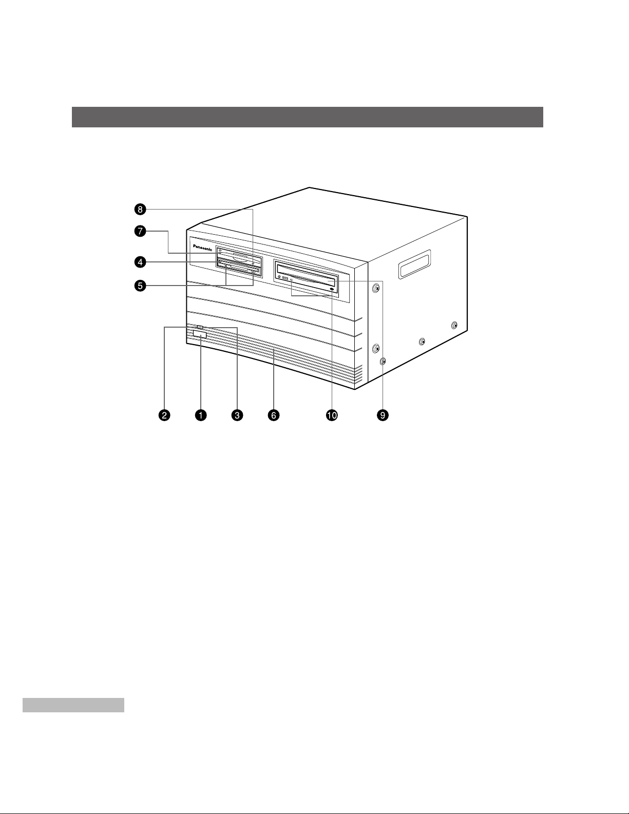
■ FRONT PANEL
1. Power On/Off Switch
Turns the power of this unit on and off.
Notes:
1. Be sure to turn on the power of this unit after
turning on the Hard Disk Box.
2. Do not turn off the power of this unit while the
Nonlinear AV Workstation System software is
running.
2. Power Indicator (RED)
Lights by turning on the power.
3. HDD Indicator (GREEN)
Lights up while the HDD operates.
4. 3.5” Floppy Disk Drive
5. Floppy Disk Indicator/Eject Button
Eject button...Ejects the Floppy Disk.
Indicator........Lights during an access of the floppy
disk.
6. Front Panel
Caution: Do not interrupt the Vent Hole on this
panel.
7. ZIP Drive
8. ZIP Indicator/Eject Button
Lights during an access of the ZIP.
Ejects the ZIP.
9. CD-ROM Drive
10. CD-ROM Indicator/Eject Button
Eject button...Ejects the CD-ROM.
Indicator........Lights during an access of the
CD-ROM.
Page 6
4
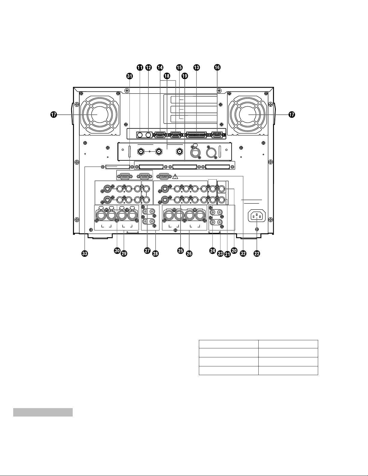
11.KEYBOARD Connector (KB)
Connects with the keyboard (locally purchase).
If the cable is too short to connect, use the Key
Board Extension Cable (accessory).
12.MOUSE Connector (MOUSE)
Connects with the Mouse (locally purchase).
When the cable is too short to connect, use the
Mouse Extension Cable (accessory).
13.PRINTER Connector (PRINTER)
Connects with the printer.
14.SERIAL1 / 2 Connectors (SERIAL 1/SERIAL 2)
Connects with equipment having RS-232C Interface
Connectors.
15.PCI Slots
Refer to qualified service personnel.
16.S-VGA Connector (S-VGA)
Connects with the computer display.
The applicable display parameters are shown below.
Resolution: 1024 x 768
Horizontal Scanning Frequency: 48 kHz
Vertical Scanning Frequency: 60 Hz
17.Fan
Supplies steady forced air through intake and filter.
Note: After extensive use the fans need to be
replaced periodically.
18.SDI Board Slots
〜AC IN
IN1
IN2
LR
RL
OUT1
OUT2
AUDIO
OUT
LR
OUT1
LR
OUT2
BALANCED
AUDIO OUT
L
IN1 IN2
BALANCED
AUDIO IN
LRR
CONTROL 1 CONTROL 2 JOG PAD
Y/C
COMPOSITE
Y
P
B PR
IN1→
IN2→
G/L IN
LOOP
75Ω
Y/C COMPOSITE Y P
B PR
ADV REF
OUT
OUT1→
OUT2→
TC IN
VIDEO
IN
AUTO
VIDEO
OUT
TC OUT
AUDIO
IN
SEE MANUAL
KB MOUSE SEPIAL 1
SEPIAL 2 PRINTER
S-VGA
SCSI AUDIO SCSI VIDEO 1 SCSI VIDEO 2 SCSI VIDEO 3
VIDEO(DIGITAL)
IN
OUT
AUDIO
(AES/EBU)
IN
OUT
■ REAR PANEL
Operating Time Operating Life
8-hour everyday use 6-year
12-hour everyday use 4-year
24-hour everyday use 2-year
Page 7

5
19.SCSI VIDEO Connectors (SCSI VIDEO 1-3)
Connects with the SCSI Video Connector of the Hard
Disk Box AY-EB2000 or WJ-EB1000 via the optional
SCSI Cable AY-CA68SR3 for AY-EB2000 or AYCA50SR3 for WJ-EB1000.
20.TC (Time Code) IN Connector (TC IN)
Connects with a VCR having LTC time code signal
output connector to improve editing accuracy.
21.TC (Time Code) OUT Connector (TC OUT)
Connects with a VCR having LTC time code signal
input connector.
The signal supplied from this connector is not
looped through.
22.AC Inlet
Connect the AC Power Cord (provided).
23.AUDIO OUT 1/2 Jacks
(AUDIO OUT OUT1, OUT2 L/R)
Supply the audio signals.
24.ADV-REF OUT Connector (ADV-REF OUT)
Supplies the Advance Reference Signal to the VCR
having the time base corrector inside (or AUX video
source).
25.Video Output Connectors
(VIDEO OUT1/OUT2 Y/C, COMPOSITE, Y, P
B, PR)
Supplies the video signal to the monitor or VCR.
26.AUDIO OUT 1/2 Connectors
(BALANCED AUDIO OUT, OUT1/OUT2)
Supply the audio signals.
27.G/L IN / AUTO Connectors (G/L, IN/AUTO)
The gen-lock signal is supplied to these connectors
(Be sure to terminate the video signal output from
these connectors).
By connecting with the G/L AUTO Connector, the
video signal is automatically unterminated.
Caution:
If a gen-lock signal is supplied to the G/L connector during playback or recording, it may
cause the video to roll or cause other system
malfunction.
Stop the playback or recording, then make a
connection to the G/L connector again.
28.AUDIO IN 1/2 Jacks (IN1, IN2 L/R) (Unbalanced)
Accepts the audio signal.
The audio signal supplied to these jacks can be
saved in the Hard Disk Box.
When the audio signal is supplied to the L side only,
a monaural audio signal is made.
29.AUDIO IN 1/2 Connectors
(BALANCED AUDIO IN IN1 L/R, IN2 L/R)
Accepts the audio signal.
The audio signal supplied to these connectors can
be saved in the Hard Disk Box.
30.Video 1/2 Input Connectors
(VIDEO IN1/IN2 Y/C, COMPOSITE, Y, P
B, PR)
Accepts the video signals to be saved in the Hard
Disk Box.
Select the connector, either Composite, Y/C or
Component, according to the type of video signal.
The selection of either Video 1/Video 2 is available
on the PC monitor screen.
31.CONTROL 1/2 Connectors
(CONTROL 1/CONTROL 2) (9-pin)
Supplies the control signal (for the recording or play
back mode) to equipment having an RS-422
Interface Connector.
Be sure to supply the video signal of the VCR connected with CONTROL 1 to VIDEO IN 1, and likewise
with the VCR connected to CONTROL 2.
32.JOGPAD Connector (JOGPAD)
Connects with the Jogpad (provided).
33.SCSI AUDIO Connector (SCSI AUDIO)
Supplies the audio signal to the SCSI Audio
Connector of the optional Hard Disk Box via the
optional SCSI Cable AY-CA68SR3 for AY-EB2000 or
AY-CA50SR3 for WJ-EB1000.
Page 8
6
OPEN
OK
UNDO SHIFT
TRIM
MODE
D
IV
ID
E
D
E
LE
T
E
ZOOM /
G
O
TO
/
PLAY/STOP
M
AR
K
IN
M
A
R
K
O
U
T
/
/
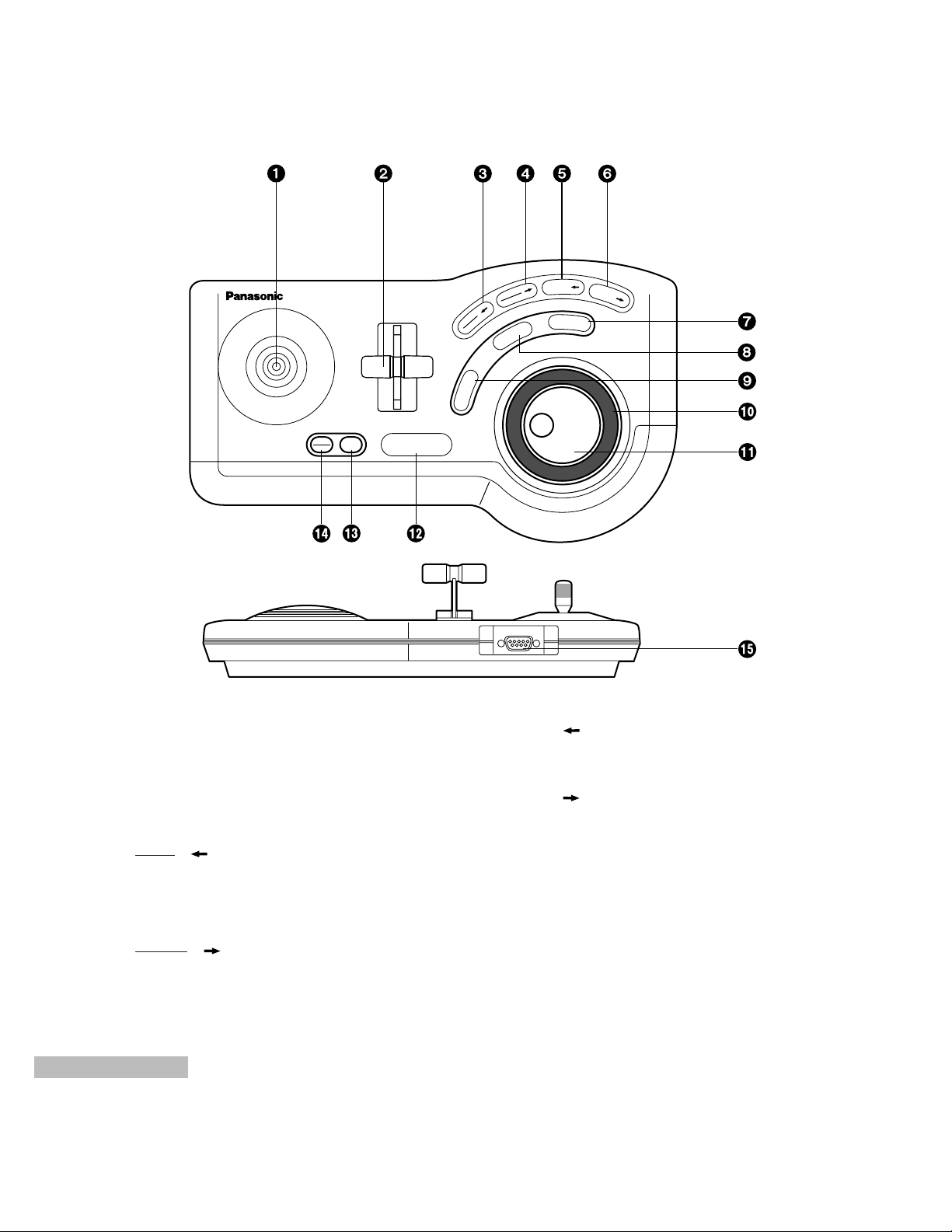
■ JOG PAD
1. Positioner
Moves the selection cursor (when selection is confirmed).
2. Wipe Lever
Controls Wipe, Key Size, and Audio Level.
3.
TRIM
/
MODE
Switches edit modes (Insert - Replace - Cover)
(SHIFT + TRIM/MODE) Turns Trim mode On/Off.
(during transition)
4.
DIVIDE
/
DELETE
Deletes a clip.
(SHIFT + DIVIDE / DELETE) Divides a clip.
5. ZOOM /
Zooms in the time line.
(SHIFT + ZOOM) Zooms out the time line.
6. GOTO /
Jumps to the starting or editing mark.
(SHIFT + GOTO) Jumps to the beginning or end
of a sequence.
7. MARK OUT
Sets or cancels the ending mark.
(SHIFT + MARK OUT) Selects the grip of the OUT
point.
Page 9

7
8. MARK IN
Sets or cancels the starting mark.
(SHIFT + MARK IN) Selects the grip of the IN
point.
9. PLAY/STOP
Plays back or stops.
(SHIFT + PLAY /STOP) Plays back between the
starting and ending marks.
10.Shuttle Ring
Plays back video and audio forward (clockwise) or in
reverse (counterclockwise) with variable speed.
11.Jog Dial
Plays back video and audio forward (clockwise) or in
reverse (counterclockwise) frame by frame.
12.SHIFT
Switches button functions.
13.UNDO
Cancels the immediately previous operation.
14.
OPEN
OK
Opens the selected panel or selects a panel and
closes the previous panel.
15.Jog Pad Connector
Connects with the Main Unit by using the Jog Pad
Cable (accessory).
Page 10
8
SCSI Cable (AY-CA68SR3)
(AY-CA50SR3)
Coaxial Cable
With BNC Connector
These connections should be made by qualified service personnel or system installers.
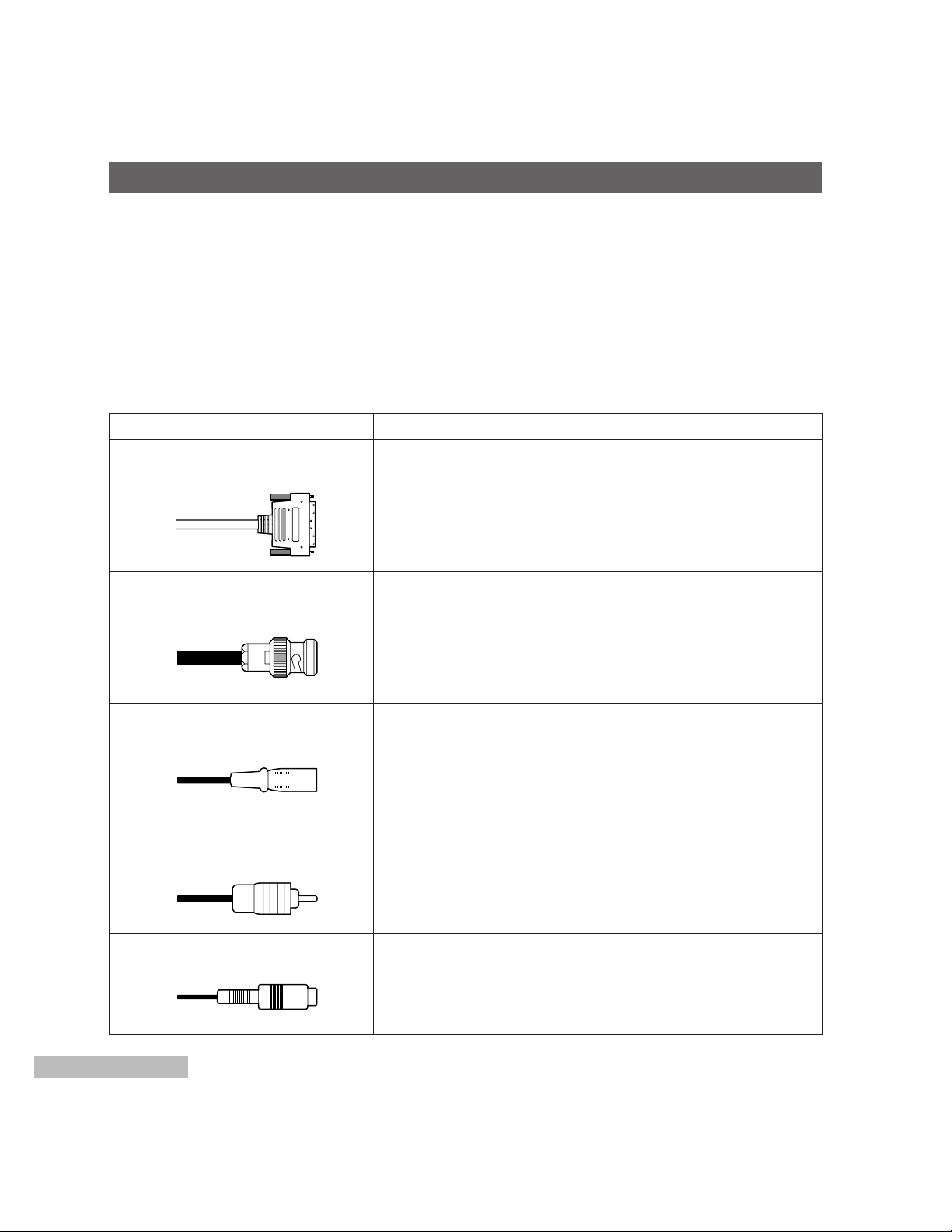
■ Cable Information
Necessary cables for this system are shown below.
SCSI Cable (AY-CA68SR3/AY-CA50SR3) Connects with the HDD-BOX.
Coaxial Cable (with BNC Connector) Connects with the VCR or Monitor.
2-conductor shielded cable (with XLR-3-12C Connector) Connects with the powered speaker), cassette tape recorder,
CD player, VCR.
S-VHS cable connects with the S-VHS VCR.
Cable Use
HDD-BOX Connection
VCR (Video)/Monitor Connection
2-conductor shielded Cable
With XLR-3-12C Connector
VCR (Audio) Connection
RCA Pin-plug Cable
RCA W Pin-plug Cable
Power speaker Connection
Cassette Tape Recorder/CD Player/S-VHS VCR (Audio) Connection
S-VIDEO Cable
S-VHS VCR Connection
CONNECTION
Page 11

9
Coaxial Cable / BNC Connector
Interconnection of BNC Coaxial Cable
XLR-3-12C Connector
Connect the 2-conductor shielded wire as shown below.
RCA Pin-plug
Connect single-conductor shielded wire as shown below.
BNC Connector
Inner BNC Connector
3 mm
Screw
BNC Connector
BNC Interconnector
Hot
Ground
Washer
(Common)
(Hot)
(Cold)
3-pin XL-type
male connector
Soldering
Coaxial Cable
Page 12

The following system connections should be made by qualified service personnel or system installers.
■ HDD-BOX Connection
1. HDD Installation to HDD-BOX
Refer to the Instruction Manual of the AY-EB2000 or WJ-EB1000 Hard Disk Box Installation instructions.
2. Connection from HDD-BOX to the Unit (AY-EB2000 or WJ-EB1000)
To connect HDD-BOX to the Unit, the optional SCSI cable AY-CA68SR3 for AY-EB2000 or AY-CA50SR3 for WJEB1000 is necessary.
Caution:
1. For single HDD-BOX connection to the Unit (AY-EB2000 or WJ-EB1000)
Confirm that the HDD-BOX is set to “Terminated”.
2. For plural HDD-BOXes connection to the Unit (AY-EB2000 or WJ-EB1000)
Confirm that the first HDD-BOX (the farthest HDD-BOX from the Unit) is set to “Terminated”.
Also confirm that the other HDD-box(es) between the first HDD-BOX (Terminated) and the Unit are set to
“Unterminated”.
~AC IN
SCSI AUDIO
SCSI ID
AUDIO
VIDEO 1
VIDEO 2
VIDEO 3
0 1 2 3
SCSI VIDEO 1 SCSI VIDEO 2 SCSI VIDEO 3
IN OUT IN OUT IN OUT IN OUT
~AC IN
SCSI AUDIO
SCSI ID
AUDIO
VIDEO 1
VIDEO 2
VIDEO 3
0 1 2 3
SCSI VIDEO 1 SCSI VIDEO 2 SCSI VIDEO 3
IN OUT IN OUT IN OUT IN OUT
~AC IN
SCSI AUDIO
SCSI ID
AUDIO
VIDEO 1
VIDEO 2
VIDEO 3
0 1 2 3
SCSI VIDEO 1 SCSI VIDEO 2 SCSI VIDEO 3
IN OUT IN OUT IN OUT IN OUT
〜AC IN
IN1
IN2
LR
RL
OUT1
OUT2
AUDIO
OUT
LR
OUT1
LR
OUT2
BALANCED
AUDIO OUT
L
IN1 IN2
BALANCED
AUDIO IN
LRR
CONTROL 1 CONTROL 2 JOG PAD
Y/C
COMPOSITE
Y
P
B PR
IN1→
IN2→
G/L IN
LOOP
75Ω
Y/C COMPOSITE Y P
B PR
ADV REF
OUT
OUT1→
OUT2→
TC IN
VIDEO
IN
AUTO
VIDEO
OUT
TC OUT
AUDIO
IN
SEE MANUAL
KB MOUSE SEPIAL 1
SEPIAL 2 PRINTER
S-VGA
SCSI AUDIO SCSI VIDEO 1 SCSI VIDEO 2 SCSI VIDEO 3
VIDEO(DIGITAL)
IN
OUT
AUDIO
(AES/EBU)
IN
OUT
10
SYSTEM CONNECTION
First HDD-BOX
SCSI ID = 6
Second HDD-BOX
SCSI ID = 5
nx HDD-BOX
SCSI ID =
4, 3, ........., 0
SCSI Cable
SCSI AUDIO OUT
SCSI VIDEO1 OUT
SCSI VIDEO2 OUT
SCSI VIDEO3 OUT
SCSI VIDEO3 IN
SCSI VIDEO2 IN
SCSI VIDEO1 IN
SCSI AUDIO IN
SCSI Cable
SCSI AUDIO
SCSI VIDEO 1
SCSI VIDEO 2
SCSI VIDEO 3
[System example
with AY-EB2000]
Terminated
Unterminated
Unterminated
Page 13

11
■ Key Board, Mouse and Jog Pad Connections
● Key Board and Mouse
Connect the KEY BOARD Connector of this unit to the Key Board.
Connect the MOUSE Connector of this unit to the Mouse.
Use the Key Board Extension Cable/Mouse Extension Cable (accessory) for the extension.
〜AC IN
IN1
IN2
LR
RL
OUT1
OUT2
AUDIO
OUT
LR
OUT1
LR
OUT2
BALANCED
AUDIO OUT
L
IN1 IN2
BALANCED
AUDIO IN
LRR
CONTROL 1 CONTROL 2 JOG PAD
Y/C
COMPOSITE
Y
P
B PR
IN1→
IN2→
G/L IN
LOOP
75Ω
Y/C COMPOSITE Y P
B PR
ADV REF
OUT
OUT1→
OUT2→
TC IN
VIDEO
IN
AUTO
VIDEO
OUT
TC OUT
AUDIO
IN
SEE MANUAL
KB MOUSE SEPIAL 1
SEPIAL 2 PRINTER
S-VGA
SCSI AUDIO SCSI VIDEO 1 SCSI VIDEO 2 SCSI VIDEO 3
VIDEO(DIGITAL)
IN
OUT
Esc F1 F2 F3 F4 F5 F6 F7 F8 F9 F10 F11 F12
Print
Screen
Pause
Tab
Caps Lock
Shift
Ctrl
Alt
Alt
Ctrl
Shift
Enter
Insert Home
Delete End
4
1
End
0
Ins.Del
5
6
8
2
Enter
Page
Up
*
Break
SysRq
!
1
Scroll
Lock
Page
Down
Num
Lock
7
Home9PgUp
3
PgDn
Panasonic
@
2 #3 $4 %5 ^6 &7 *8 (9 )0 _- +=
←Backspace
Q W E R T |
\
Y U I O P {[}
]
A S D F G H J K L :;"
'
~
`
Z X C V B N M <,>.?
/
AUDIO
(AES/EBU)
IN
OUT
Key Board
Key Board
Extension Cable
(accessory)
Mouse
Mouse
Extension Cable
(accessory)
Control Unit
Page 14

〜AC IN
IN1
IN2
LR
RL
OUT1
OUT2
AUDIO
OUT
LR
OUT1
LR
OUT2
BALANCED
AUDIO OUT
L
IN1 IN2
BALANCED
AUDIO IN
LRR
CONTROL 1 CONTROL 2 JOG PAD
Y/C
COMPOSITE
Y
P
B PR
IN1→
IN2→
G/L IN
LOOP
75Ω
Y/C COMPOSITE Y P
B PR
ADV REF
OUT
OUT1→
OUT2→
TC IN
VIDEO
IN
AUTO
VIDEO
OUT
TC OUT
AUDIO
IN
SEE MANUAL
KB MOUSE SEPIAL 1
SEPIAL 2 PRINTER
S-VGA
SCSI AUDIO SCSI VIDEO 1 SCSI VIDEO 2 SCSI VIDEO 3
VIDEO(DIGITAL)
IN
OUT
AUDIO
(AES/EBU)
IN
OUT
12
● Jog Pad Connection
Connect the JOGPAD Connector of this unit to the Jog Pad.
After connecting, tighten the screws on the Jog Pad Cable (provided).
Jog Pad
Tighten these screws
after the connection.
Control Unit
Jog Pad Cable
(accessory)
Page 15

13
■ Monitor Connection
● Computer Display Connection
Connect the S-VGA Connector of this unit with the computer display.
The usable computer display is shown in the following.
Resolution 1024 x 768 dot
Horizontal Scanning Frequency 48 kHz
Vertical Scanning Frequency 60 Hz
〜AC IN
IN1
IN2
LR
RL
OUT1
OUT2
AUDIO
OUT
LR
OUT1
LR
OUT2
BALANCED
AUDIO OUT
L
IN1 IN2
BALANCED
AUDIO IN
LRR
CONTROL 1 CONTROL 2 JOG PAD
Y/C
COMPOSITE
Y
P
B PR
IN1→
IN2→
G/L IN
LOOP
75Ω
Y/C COMPOSITE Y P
B PR
ADV REF
OUT
OUT1→
OUT2→
TC IN
VIDEO
IN
AUTO
VIDEO
OUT
TC OUT
AUDIO
IN
SEE MANUAL
KB MOUSE SEPIAL 1
SEPIAL 2 PRINTER
S-VGA
SCSI AUDIO SCSI VIDEO 1 SCSI VIDEO 2 SCSI VIDEO 3
VIDEO(DIGITAL)
IN
OUT
AUDIO
(AES/EBU)
IN
OUT
● VIDEO Monitor Connection
Connect the COMPOSITE Connector of this unit with the video monitor.
Computer Display
S-VGA
Cable with 15-pin Connector
VIDEO OUT (COMPOSITE)
Coaxial Cable with BNC Connector
Page 16

14
■ VCR Connection
● DVCPRO VCR
〜AC IN
IN1
IN2
LR
RL
OUT1
OUT2
AUDIO
OUT
LR
OUT1LROUT2
BALANCED
AUDIO OUT
L
IN1 IN2
BALANCED
AUDIO IN
LRR
CONTROL 1 CONTROL 2 JOG PAD
Y/C
COMPOSITE
Y
P
B PR
IN1→
IN2→
G/L IN
LOOP
75Ω
Y/C COMPOSITE Y P
B PR
ADV REF
OUT
OUT1→
OUT2→
TC IN
VIDEO
IN
AUTO
VIDEO
OUT
TC OUT
AUDIO
IN
SEE MANUAL
KB MOUSE SEPIAL 1
SEPIAL 2 PRINTER
S-VGA
SCSI AUDIO SCSI VIDEO 1 SCSI VIDEO 2 SCSI VIDEO 3
VIDEO(DIGITAL)
IN
OUT
AUDIO
(AES/EBU)
IN
OUT
AUDIO OUT (AES/EBU)
ADV REF Output
VIDEO OUT (P
R)
Signal Generator
<If necessary>
VIDEO OUT (P
B)
VIDEO OUT (Y)
VIDEO OUT (DIGITAL)
AUDIO OUT (R)
AUDIO OUT (L)
TC (LTC) Output
VIDEO IN (Y)
TC (LTC) Input
RS-422
AUDIO IN (L)
AUDIO IN (R)
VIDEO IN (P
B)
VIDEO IN (P
R)
AUDIO IN (AES/EBU)
VIDEO IN (DIGITAL)
DVCPRO VCR
Coaxial Cable
(with BNC Connector)
2-conductor Shielded Cable
(with XLR-3-12C Connector)
Coaxial Cable
(with BNC Connector)
2-conductor Shielded Cable
(with XLR-3-12C Connector)
Page 17

15
● S-VHS VCR
〜AC IN
IN1
IN2
LR
RL
OUT1
OUT2
AUDIO
OUT
LR
OUT1
LR
OUT2
BALANCED
AUDIO OUT
L
IN1 IN2
BALANCED
AUDIO IN
LRR
CONTROL 1 CONTROL 2 JOG PAD
Y/C
COMPOSITE
Y
P
B PR
IN1→
IN2→
G/L IN
LOOP
75Ω
Y/C COMPOSITE Y P
B PR
ADV REF
OUT
OUT1→
OUT2→
TC IN
VIDEO
IN
AUTO
VIDEO
OUT
TC OUT
AUDIO
IN
SEE MANUAL
KB MOUSE SEPIAL 1
SEPIAL 2 PRINTER
S-VGA
SCSI AUDIO SCSI VIDEO 1 SCSI VIDEO 2 SCSI VIDEO 3
VIDEO(DIGITAL)
IN
OUT
AUDIO
(AES/EBU)
IN
OUT
AUDIO OUT (L)
AUDIO OUT (R)
VIDEO OUT (Y/C)
VIDEO IN (Y/C)
AUDIO IN (L)
AUDIO IN (R)
S-VHS VCR
RCA Pin-plug Cable
RCA Pin-plug Cable
S-Video Cable
S-Video Cable
Page 18

16
■ Powered Speaker, Cassette Tape Recorder or CD Player Connection
〜AC IN
IN1
IN2
LR
RL
OUT1
OUT2
AUDIO
OUT
LR
OUT1
LR
OUT2
BALANCED
AUDIO OUT
L
IN1 IN2
BALANCED
AUDIO IN
LRR
CONTROL 1 CONTROL 2 JOG PAD
Y/C
COMPOSITE
Y
P
B PR
IN1→
IN2→
G/L IN
LOOP
75Ω
Y/C COMPOSITE Y P
B PR
ADV REF
OUT
OUT1→
OUT2→
TC IN
VIDEO
IN
AUTO
VIDEO
OUT
TC OUT
AUDIO
IN
SEE MANUAL
KB MOUSE SEPIAL 1
SEPIAL 2 PRINTER
S-VGA
SCSI AUDIO SCSI VIDEO 1 SCSI VIDEO 2 SCSI VIDEO 3
VIDEO(DIGITAL)
IN
OUT
AUDIO
(AES/EBU)
IN
OUT
Powered Speakers
AUDIO OUT 1 (R)
RCA Double Pin-plug Cable
RCA Pin-plug Cable
AUDIO OUT 1 (L)
AUDIO IN 1
AUDIO IN 2
AUDIO OUT 2
Cassette Player
CD Player
Page 19

17
■ Power On
1. Turn on the power of the HDD-BOX and all peripheral equipment in the system.
The power indicator of the HDD-BOX lights red.
2. Turn on the power of this unit.
The Power Indicator of this unit lights and the system
is activated.
■ Power Off
Caution:
Be sure to turn off the power of this unit only
after the nonlinear AV workstation software is
closed.
Otherwise, the data on the HD or HDD unit may
be corrupted.
1. Quit the software and Windows.
Refer to the User's Manual of the AY-AS2000 (application software) for details.
2. Turn off the power of the peripheral equipment.
3. Turn off the power of this unit.
POWER / HDD
Nonlinear AV Workstation AY-NE2000
Power Indicator/HDD Indicator
Power On/Off Switch
POWERING MAIN UNIT ON AND OFF
Page 20

18
Tool Box
Special Button
OPERATING PROCEDURES
Refer to the User’s Manual or Reference Manual for more details.
■ Starting the System
1. Turn on the power of the peripheral equipment in the system.
2. Then turn on the Main Unit.
The system starts and the initial window (Tool Box, Bin Manager or Bin Window) appears on the Computer Display.
Computer Display is shown below.
Bin Manager Bin Window
■ Closing the System
1. Click “Exit” on the Tool Box.
2. Click “OK”.
3. Turn off the power of the peripheral equipment in the
system and then the Main Unit.
Page 21

19
■ Installing the Software Package
You should install the application program (provided on
CD-ROM with the AY-AS2000) into the Main Unit to operate this system.
Confirm the connection to the HDD-BOX before installing
the software package. If the connection is incorrect, error
or startup troubles may occur.
Note: Back-up Windows 95 before the installing the
application program and font.
Install an Application Program
1. Turn on the peripheral equipment of the system.
2. Then turn on the Main Unit.
Windows 95 starts up.
3. Click “START”.
The Pull Down menu is displayed.
4. Click “RUN....”.
5. Insert the CD-ROM into the CD-ROM Drive.
6. Type “G:\AS2000\DISK1\SETUP” from the keyboard
and click “OK”.
The initial setup window appears.
7. Click “Continue”.
The input screen appears.
8. Click “Continue”.
Then type your name, company and the serial number of the main unit from the keyboard.
9. Click “Continue”.
The Locale dialog panel is displayed.
10.Select “NTSC [English]” and click “Continue”.
The Hardware dialog panel is displayed.
Click “WJ-HX1000/AY-NE2000 Series”.
11.Click “Continue”.
The startup dialog panel is displayed.
Click “Yes”.
12.Click “Continue”.
The confirmation dialog panel is displayed.
Check the all description, and click “Install”.
■ Upgrade for JOG Microprocessor
Program
1. The first time you startup the computer after
installing, following message may be displayed.
“Program version built in JOG microprocessor is
different from system required. The program will be
rewritten.”
In this case, click “OK”. JOG microprocessor program (built-in flash memory) will be rewritten automatically.
2. While rewriting, following panel and message will be
displayed. DO NOT turn off, or reset the computer
while rewriting.
“Preparing for writing new program.”
3. When rewriting is finished correctly,
“Writing new program succeeded!”
will be displayed. Click “OK”.
4. When rewriting is finished incorrectly,
“An error is occurred while writing. Restart the system
after turn off the power. Toolbox will be finished.”
will be displayed.
Click “OK” and turn off the computer. The next time
startup the computer, a message will be displayed
which inform you of automatically rewriting the JOG
microprocessor program.
Note: In case you turn off or reset the computer while
rewriting, the same message will be displayed.
If the JOG microprocessor program data can not
be restored, please contact to the nearest
Panasonic dealer.
■ Installing Fonts
1. Turn on the Main Unit.
The application program starts up.
2. Double click “Special” in the Tool Box.
The Setup panel appears.
3. Click “Font” on the Setup panel.
Click “Append All” and combine the necessary fonts
with the application program.
Page 22

20
Attribute Setup Panel
Device Setup Window
Connection Setup Panel
■ Device Setting
Refer to the Reference Manual of AY-AS2000 for more
details.
1. Double click “Special” in the Tool Box.
2. Double click “Device” in the Setup Panel.
The “VCR SETUP” window is displayed.
3. Click “Add” in the Device Window.
The “Connection Setup” panel is displayed.
4. Set the necessary items.
6. Set Function, Communication and Control Attributes.
5. In case that there is not VCR name that you use, in
the Device Type area, click “Add”.
The “Attribute Setup” panel is displayed.
Page 23

21
DISK Configuration Panel
■ Operation Confirmation
Refer to the Reference Manual for the AVHDD Maintenance tools.
1. Double click “Special” in the Tool Box.
“Setup Panel” is displayed.
2. Double click “AV HDD” to display the “AV HDD
Maintenance tool” panel.
3. Click “disk configuration” to display the “Disk
Configuration” panel.
4. The HDD model numbers are displayed in the “Disk
Configuration” panel.
Note: All HDD model numbers should be displayed in
blue.
No Display
• Confirm the SCSI cable connection between the
HDD-Box and main unit.
• If no problem is found with the connection, refer to
qualified service personnel.
Black Display
• Initialization of the HDD displayed in black (in the
“Disk Configuration” panel) is not possible.
In this case, refer to qualified service personnel.
Red Display
• Click on “Add to chain as Newdisk” for logical for-
matting.
Caution:
• It is important to make a back-up copy of HDDs, and
Windows 95. Backing up your files and disks
ensures that you won't lose information if the original
is lost or damaged.
• For backing up, 30 floppy disks are required.
■ Back-up of Windows 95
1. Format 29 floppy disks.
2. Click [EXIT], then click [Restart Windows].
3. Click [Start] and select [Programs] → [Accessories]
→ [System Tools Create System Disks].
4. Insert the floppy disk into the Floppy Disk Drive
according to the message.
5. Write WIN-0,1...28 on the labels of the backed-up
floppy disks.
Caution:
Only 1 set of back-up disks can be made.
■ Reloading Windows
1. Keep the 29 Windows 95 back-up disks ready.
2. Insert the [WIN-0] floppy disk into the FDD, and turn
the main power on.
3. Reload the floppy disks from [WIN-0] to [WIN-28].
Page 24

22
● Gen-lock Adjustment
Phase adjustments must be performed by using the
switches inside the Front Panel when external synchronizing signals are supplied to the system.
For the example, the gen-lock adjustment is shown below
using a two-channel oscilloscope (or wave form monitor),
vector scope and signal generator.
1. Connect the oscilloscope, vector scope and signal
generator with the Main unit AY-NE2000.
The reference signal is supplied from the signal generator.
The video signal should be a composite signal.
2. Turn on the external reference switch of the vector
scope.
3. Remove the Front Panel by releasing 4 screws.
POWER / HDD
Nonlinear AV Workstation AY-NE2000
VR1
Sub-
Carrier
Fine
Control
SW1
Sub-
Carrier
Control
SW2 VR2
Horizontal
Phase
Fine
Control
Horizontal
Phase
Control
SW3
Signal Generator
VIDEO IN
Video Monitor
EXT
G/L IN
EXT
CH2 CH2
Video Signal
Screws
Screws
AY-NE2000
VIDEO OUT
(COMPOSITE)
EXT
SW
ON
75Ω
ADJUSTMENT
Page 25

23
● Color Phase Control
The sub-carrier can be adjusted by using the SW1 and
VR1.
1. Turn the SW1 to clockwise; 0°, 90°, 180°, 270°
Turn the SW1 to counterclockwise;
270°, 180°, 90°, 0°
2. Perform the fine adjustment with the VR1.
● Horizontal Phase Control
Observe the waveform of the external synchronizing
input signal (black burst signal) and video output signal
on a two-channel oscilloscope.
Then match the horizontal phase of both signals by using
the SW2, SW3 and VR2.
1. The horizontal phase course 1 adjustment can be
performed with the SW3 (1 µs).
2. The horizontal phase course 2 adjustment can be
performed with the SW2. (70 ns).
3. The horizontal phase fine adjustment can be performed with the VR2.
VIDEO OUT
Reference signal
Reference signal
VIDEO OUT
● Install the Front Panel
After the above adjustments, install the front panel as
shown below.
1. Place the panel as shown above figure.
Insert the slot on the panel to the protrusion.
2. Press the panel to the front of the Main Unit.
3. Confirm the Front Panel is tightened firmly.
4. Tighten 4 screws.
ProtrusionSlot
Screws
Screws
UnitFront Panel
Page 26

24
The system memory should be as follows:
Type 168-pin DIMM type
Memory Type SDRAM
Memory Capacity 32MB, 64MB, 128MB
Power Voltage 3.3V
Operational Speed More than 100MHz
ECC Not required
SPC Not required
There are two types of factory setting of memory configuration depending on the production period. The configuration
of additional memory varies. Before installing additional
system memory, you should check which type of memory
you have.
The two types of memory configuration are as follows:
Memory board installed in DIMM Slot 1
(1) Factory Setup
DIMM1 32MB
DIMM2 not used
DIMM3 not used
Total 32MB
(2) Add 32MB Memory
DIMM1 32MB 32MB
DIMM2 32MB 32MB
DIMM3 not used 32MB
Total 64MB 96MB
Note: The memory you add should be the same type
as the original one which includes 16 pieces of
memory in both sides of the module.
Memory board installed in DIMM Slot 2
(1) Factory Setup
DIMM1 not used
DIMM2 32MB
DIMM3 not used
Total 32MB
(2) Add 32MB Memory
DIMM1 not used
DIMM2 32MB
DIMM3 32MB
Total 64MB
Note: The memory you add should be the same type
as the original one which includes 4 pieces of
memory in single side of the module.
64MB, 128MB should be arranged as follows in both
configurations above;
(3) Add 64MB Memory
DIMM1 not used not used
DIMM2 64MB 64MB
DIMM3 not used 64MB
Total 64MB 128MB
(4) Add 128MB Memory
DIMM1 not used not used
DIMM2 128MB 128MB
DIMM3 not used 128MB
Total 128MB 256MB
ADD SYSTEM MEMORY
VGA Parallel COM2 COM1 Mouse Keybd
DIMM3,2,1
321
DIMM Socket
Configuration : 16 pieces of memory in both
sides of the module.
Configuration : 4 pieces of memory in single side
of the module.
Page 27

25
SPECIFICATIONS
Video
Video Input
[Analog]
Input Connectors: 2 sources (selectable from Composite. Y/C, Y/PB/PR)
Composite: 1.0 V[p-p]/75 Ω (BNC)
Y /C: Y: 1.0V[p-p]/75 Ω
C: 0.286 V[p-p]/75 Ω (Y/C terminal)
Component: Y: 1.0V[p-p]/75 Ω (BNC)
P
B/PR: 0.486V[p-p] or 0.7V[p-p],
75 Ω (BNC) (Setup 7.5 IRE)
[SDI (Option)]
SMPTE259M 75 Ω (BNC) with active loop-through
Video Output
[Analog]
Output Connector: 2 outputs (simultaneously from Composite, Y/C, Y/PB/PR)
Composite: 1.0V[p-p]/75 Ω
Y/C: Y: 1.0V[p-p]/75 Ω
C: 0.286V[p-p]/75 Ω (Y/C terminal)
Component: Y: 1.0V[p-p]/75 Ω (BNC)
P
B/PR: 0.486V[p-p] or 0.7V[p-p], 75 Ω (BNC) (Setup 7.5 IRE)
[SDI (Option)]
SMPTE259M 75 Ω (BNC)
Synchronization
Gen-Lock Input: 1.0V[p-p]/75 Ω (BNC), with loop-through output (x1)
ADV.REF output: Sync: 0.286V[p-p], 75 Ω
Burst: 0.286V[p-p], 75 Ω
Audio Input
[Analog]
Selectable from 4 sources
Source 1/2: +4dBu, 0dBu, –20dBu selectable, 600 Ω balanced (3-pin XLR connector)
Source 3/4: −6dBs, 20 kΩ, unbalanced (RCA pin jack)
[AES/EBU (Option)]
AES/EBU 110Ω (XLR)
Audio Output
[Analog]
4 outputs (simultaneous)
Ch. 1/2: +4dBu, 0dBu, –20dBu selectable, 47 Ω balanced (3-pin XLR connector)
Ch. 3/4: −6dBs, 75 Ω, unbalanced (RCA pin jack)
[AES/EBU (Option)]
AES/EBU 110Ω (XLR)
Page 28

26
Other Inputs/Outputs
LTC time code Input: x1 (BNC)
LTC time code output: x1 (BNC)
SCSI connector: x4 (Audio, Video 1, Video 2, Video 3, SCSI-2 standard, 68-pin half pitch
connector, pin type)
VCR control connector: RS-422, 9 pin x2 (D-sub)
Jog Pad connector: 9 pin x1 (D-sub)
PC
CPU: Pentium Processor, MMX 200 MHz
OS: Windows 95
Main Memory: 32MB DIMM 168-pin SDRAM
Built-in Hard Disk Drive: 3.2GB (E-IDE) x1
Floppy Disk Drive: 1.44MB x1
ZIP Drive: 100MB x1
CD-ROM Drive: x32 Speed
Card Slot: PCI x3 (supplied by Panasonic only)
SVGA connector: 15 pinx1 (D-Shell, female),
1024x768 dots, 256 colors,
Scanning: 48kHz (horizontal),
60 Hz (vertical)
Parallel connector: 25 pin x1 (D-Shell, female)
Serial connector: 9 pin x2 (D-Shell, male)
Mouse: 6 pin x1 (Mini-Din, female)
Keyboard: 6 pin x1 (MIni-Din, female)
Video Performance
S/N Ratio*: 55dB (Y/P
B/PR), 53dB (Y/C), 50dB (Composite)
DG, DP*: 5%, 3°
Frequency Response*: 4.5MHz, +0dB, −3dB (Y/C, Y/P
B/PR)
Sampling Frequency: 13.5MHz, 4:2:2, 8 bit component
Y/C Separation: 3 lines, digital logical comb filter
SC-H: ±30°
Compression: MOTION JPEG
Compression Quality: Q3, Q6, Q8, Q11, Q23
Recording Time: Approx. 3 min/GB (Q3)
Approx. 6 min/GB (Q6)
Approx. 7 min/GB (Q8)
Approx. 10 min/GB (Q11)
Approx. 16 min/GB (Q23)
Title Graphics
Resolution: 640 x 480 dots Y, U, V, α, 8 bit component each
Font : True type
Page 29

27
Audio Performance
S/N Ratio: More than 70dB (1kHz, XLR OUT)
Dynamic Range: More than 88dB
Total Harmonic Distortion: 0.05% (1kHz)
Frequency Response: 20kHz, +0, −3dB, 20Hz, +0, −3dB
Sampling Frequency: 48kHz, 16 bit
Mixing: Stereo 4 channels
Effector: EQ, Reverberation
Recording Time: Approx. 67min/GB
Others
EDL Output: CMX 3600, CMX340, GVG, BVE9000, AU-A950 Format
Graphic Conversion: TIFF, JPEG, TARGA, BMP, WMF, PCT
General
Power Supply: 120V AC, 60Hz
Power Consumption: 140W (with optional Video Board)
Ambient Operating Temperature: 0°C - 35°C (32°F - 95°F)
Ambient Operating Humidity: 10% - 90%
Weight: Main unit: 27.0 kg (59.5 Ibs)
Jog pad: 1.2 kg (2.6 Ibs)
Dimensions:
Main unit (W x H x D): 420 x 319 x 461 mm (16
9
/16" x 129/16" x 181/8")
Jog pad (W x H x D): 340 x 45 x 193 mm (13
3
/8" x 13/4" x 75/8")
Weight and dimensions indicated above are approximate.
Specifications are subject to change without notice.
This product might be subject, to export control regulations.
* : Without Compression
Page 30

28
Memo
Page 31

29
Memo
Page 32

7J1A198C Printed in Japan
PANASONIC CANADA INC.
5770 Ambler Drive, Mississauga, Ontario L4W 2T3 (905)238-2115
PANASONIC SALES COMPANY
DIVISION OF MATSUSHITA ELECTRIC OF PUERTO RICO, INC.
San Gabriel Industrial Park, 65th Infantry Ave., KM9.5 Carolina, Puerto Rico 00630 (809)750-4300
PANASONIC BROADCAST & DIGITAL SYSTEMS COMPANY
DIVISION OF MATSUSHITA ELECTRIC CORPORATION OF AMERICA
Executive Office:
EASTERN ZONE:
Mid-Atlantic:
Southeast Region:
Central Region:
WESTERN ZONE:
Dallas Region:
No. CA/Northwest Region:
Government Marketing Department:
3330 Cahuenga Blvd W., Los Angeles, CA 90068
(323)436-3500
One Panasonic Way 4E-7, Secaucus, NJ 07094 (201)348-7621
One Panasonic Way 4E-7, Secaucus, NJ 07094 (201)348-7621
1225 Northbrook Parkway, Ste 1-160 Suwanee, GA 30024
(770)338-6845
1707 N Randall Road E1-C-1, Elgin, IL 60123 (847)468-5200
3330 Cahuenga Blvd W., Los Angeles, CA 90068 (323)436-3500
6226 Abington Way, Houston, TX 77008 (713)802-2726
5870 Stoneridge, #3, Pleasanton, CA 94588 (925)416-5102
52 West GudeDrive, Rockville, MD 20850 (301)738-3840
 Loading...