

Page 1

Before attempting to connect or operate this product, please read these instructions completely
Professional Jog Pad
AY-JP2000
Page 2
Warning:
This equipment generates and uses radio frequency
energy and if not installed and used properly, i.e., in
strict accordance with the instruction manual, may
cause harmful interference to radio communications.
It has been tested and found to comply with the limits
for a Class A computing device pursuant to Subpart J
of Part 15 of FCC Rules, which are designed to provide reasonable protection against such interference
when operated in a commercial environment.
WARNING:
TO PREVENT FIRE OR SHOCK HAZARD, DO NOT EXPOSE THIS APPLIANCE TO RAIN OR MOISTURE.
The lightning flash with arrowhead
symbol, within an equilateral triangle,
is intended to alert the user to the
presence of uninsulated “dangerous
voltage” within the product's enclosure
that may be of sufficient magnitude to
constitute a risk of electric shock to
persons.
The exclamation point within an equilateral triangle is intended to alert the
user to the presence of important
operating and maintenance (servicing)
instructions in the literature accompanying the appliance.
The serial number of this product may be found on the
bottom of the unit.
You should note the serial number of this unit in the
space provided and retain this book as a permanent
record of your purchase to aid identification in the
event of theft.
Model No. AY-JP2000
Serial No.
CAUTION:
TO REDUCE THE RISK OF ELECTRIC SHOCK, DO
NOT REMOVE COVER (OR BACK). NO USER SERVICEABLE PARTS INSIDE.
REFER SERVICING TO QUALIFIED SERVICE PERSONNEL.
CAUTION
RISK OF ELECTRIC SHOCK
DO NOT OPEN
SA 1965
SA 1966
For U.S.A
CONTENTS
PREFACE ........................................................................................................................................................................... 1
PRECAUTIONS .................................................................................................................................................................. 1
MAJOR OPERATING CONTROLS AND THEIR FUNCTIONS ........................................................................................... 2
ACCESSORY CABLE ......................................................................................................................................................... 5
CONNECTIONS.................................................................................................................................................................. 6
INSTALLING THE SOFTWARE........................................................................................................................................... 8
SPECIFICATIONS .............................................................................................................................................................. 9
ACCESSORIES................................................................................................................................................................... 9
Page 3

3 1
• The jog pad uses the keys and jog/shuttle dial, wipe
lever, positioner and audio fader controls as well as the
number keys (0 to 9) for ensuring that non-linear editing
work will be performed very efficiently.
• The four audio faders make it possible to set the audio
levels simultaneously for four channels.
• The rotary encoders enable the modify settings and
video level to be finely adjusted.
• Frequently used functions can be allocated to the user
keys as short-cut keys.
• The trackball enables the same operations as those of
a mouse to be performed on the jog pad.
PREFACE
• Do not attempt to disassemble the unit.
In order to prevent electric shock, do not remove
screws or covers. There are no user-serviceable parts
inside.
Do refer all servicing to qualified service personal.
• Handle the unit with care.
Do not abuse the unit. Avoid striking, shaking, etc.
It could be damaged by improper handling or storage.
• Do not place heavy objects on top of the unit.
• Do not expose the unit to rain or moisture, or try to
operate it in wet areas.
Do take immediate action if the unit becomes wet. Turn
the power off and refer servicing to qualified service
personal. Moisture can damage the unit and also
create the danger of electric shock.
• Before proceeding with maintenance, disconnect the
power plug from the power outlet to ensure safety.
Failure to do this may cause electric shock.
• Do not use strong or abrasive detergents when
cleaning the unit body.
Do use a dry cloth to clean the unit when dirty.
In case the dirt is hard to remove, use a mild detergent
and wipe gently.
• In the winter season or at other times when the unit is
cold, before attempting to operate the unit, raise the
room temperature gradually so that the unit will be
warmed up. If the temperature is raised suddenly,
condensation will form inside the unit.
• Do not operate the unit beyond its temperature,
humidity or power source ratings.
Do not use the unit in an extreme environment where
high temperature or high humidity exist.
Use the unit under conditions where temperature is
within 32°F ~ 95°F (0°C ~ +35°C), and humidity is
within 10% ~ 90%.
PRECAUTIONS
Page 4
4
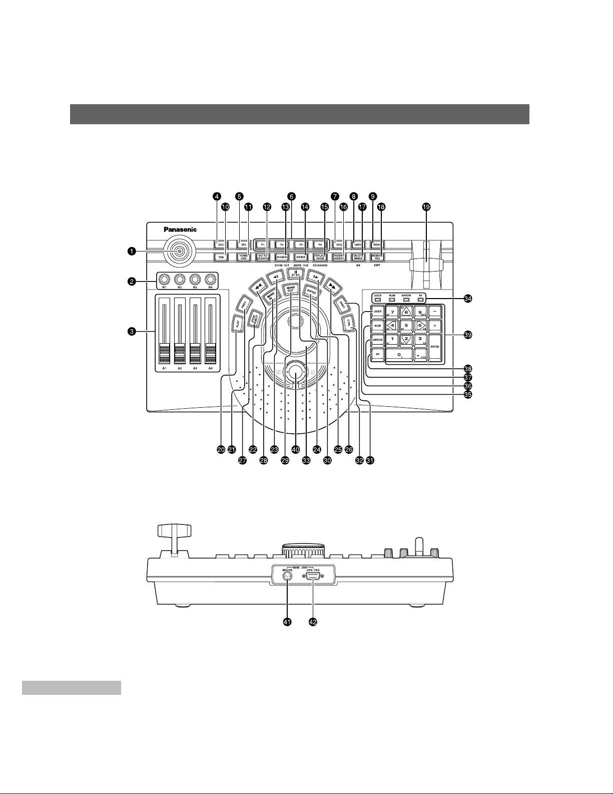
MAJOR OPERATING CONTROLS AND THEIR FUNCTIONS
Operating panel
Rear panel
For further details on operation, refer to the operating instructions of the software program you are using.
Page 5

5 3
Positioner
Used to set the key positions.
Rotary encoders [R1 ~ R4]
Used to adjust the video levels and modify settings.
Audio faders [A1 ~ A4]
Used to adjust the audio levels.
ESC
Used to cancel the setting panel.
DIG
Used to switch to the manual digitizer.
P1 ~ P4
Used to switch to the clip editor.
SEQ
Used to switch to the sequence editor.
UNDO
Used to undo the operation performed immediately
before.
REDO
Used to redo the operation which was undone by
“UNDO”.
TAB
Used in the same way as the “TAB” key on a
keyboard. It jumps ahead to the next item.
HOME/END
Used to jump to the start or end point (toggle
operation) of a sequence.
GOTO/SEARCH
Used to jump to a mark in or out point (toggle
operation).
ZOOM IN (ZOOM OUT)
Used to zoom in on (magnify) the time line. Used to
zoom out when it is pressed while “SHIFT” is held
down.
DIVIDE (MARK CUE)
Used to divide a clip.
REPLACE/ASSEM (EXCHANGE)
Used to paste (replace) clips into a sequence. With
Record To Video, it switches to the assemble mode.
INSERT/INSERT
Used to paste (insert) clips into a sequence. With
Record To Video, it switches to the insert mode.
DELETE/IMMED (BS)
Used to delete clips. With Record To Video, it
switches to the immediate mode.
When it is pressed while “SHIFT” is held down, the
two keys function as the backspace key.
REMOVE/REC (EXIT)
Used to remove clips (without moving the following
clips forward to close up the gaps left). With Record
To Video or the batch digitizer, it starts recording.
When it is pressed while “SHIFT” is held down, the
window with the focus is closed.
Wipe lever
Used to set wipe or the DVE preview or learn setting.
PLAY
Used to play a tape in an external VCR when the
time line or clips are to be played.
PREV
Used to preview wipe or DVE.
Used to rewind the tape in the external VCR.
Used to advance the tape in the external VCR frame
by frame (in the reverse direction).
/STBY
Used to set the external VCR to the still mode. When
it is pressed while “CTRL” is held down, the external
VCR is switched between the standby ON and OFF
mode.
Page 6

6
MAJOR OPERATING CONTROLS AND THEIR FUNCTIONS
Used to advance the tape in the external VCR frame
by frame (in the forward direction).
Used to fast forward the tape in the external VCR.
STOP/EJECT
Used to stop play. The external VCR is set to the
stop mode. When it is pressed while “CTRL” is held
down, the tape in the external VCR is ejected.
MARK IN
Used to set the mark in point. When it is pressed
while “SHIFT” is held down, the in point grip can be
selected. When it is pressed while “CTRL” is held
down, the mark in point is deleted.
MARK OUT
Used to set the mark out point. When it is pressed
while “SHIFT” is held down, the out point grip can be
selected. When it is pressed while “CTRL” is held
down, the mark out point is deleted.
ENTER
Used to enter the selected items. With the batch
digitizer, it enters the in and out points.
SHIFT
Used to select the functions of the keys.
CTRL
Used to select the functions of the keys.
Jog/shuttle dial
Jog and shuttle modes are selected (toggle
operation) by pressing down the dial.
In jog mode, the tape is played frame by frame in the
forward direction (when the dial is turned clockwise) or
reverse direction (when it is turned counterclockwise).
In shuttle mode, the tape is played at a variable
speed in the forward direction (when the dial is
turned clockwise) or reverse direction (when it is
turned counterclockwise).
LED
The lighted LED shows the number key mode. The
mode is selected by pressing the “USER”, “NUM”,
“ARROW” and “AV” keys.
USER
Used to switch to the user mode.
In the user mode, the number keys perform the
functions which have been allocated to them.
Frequently used functions can be allocated to the
user keys.
For details on how to allocate these functions, refer
to the operating instructions of the software program
you are using.
NUM
Used to switch to the number input mode.
In the number input mode, the number keys function
as number input keys.
ARROW
Used to switch to the cursor mode.
In the cursor mode, the number keys (2, 4, 6 and 8
keys) function as arrow keys.
AV
Used to switch to the track selection mode.
In the track selection mode, the number keys
function as track selection keys.
For further details on operation, refer to the operating
instructions of the software program you are using.
Number keys
The way in which these keys are used differs
depending on the mode (“USER”, “NUM”, “ARROW”
and “AV”). The “+” and “–” keys are used to
advance the images frame by frame.
The ENTER key enters the selected item.
Trackball
This can perform the same operations as those of a
mouse.
Connect the trackball cable following the instructions
in
Connections.
[MOUSE] connector
The trackball cable (supplied accessory) is
connected to this connector.
[JOGPAD] connector
The jog pad cable (VCR/JOGPAD cable) is
connected to this connector.
Page 7

7 5
ACCESSORY CABLE
Track Ball Cable
Jogpad Mouse
Connector
Mini DIN
6-pin type
Mouse Connector
on Main Unit
Mini DIN
6-pin type
Page 8

8
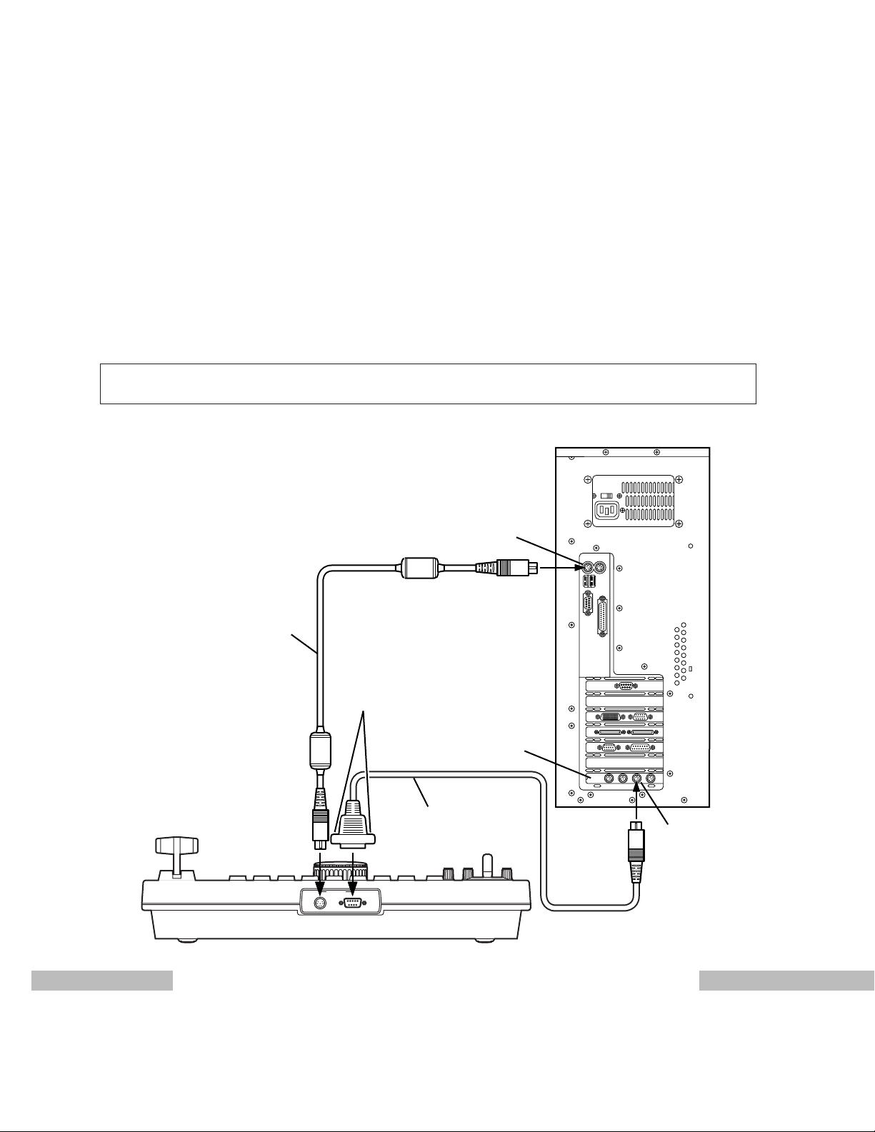
CONNECTIONS
Ask your dealer to do this.
Connection with the AY-NE2000, WJ-MX1000 series or WJ-MX1200 series
Plug one end of the jog pad connecting cable (accessory supplied with the AY-NE2000, WJ-MX1000 series and
WJ-MX1200 series) into the connector on the rear panel of the jog pad and the other end into the JOGPAD connector on
the rear panel of the main unit, and then tighten the screws.
Plug one end of the trackball connecting cable (supplied accessory) into the connector on the rear panel of the jog pad
and the other end into the MOUSE connector on the rear panel of the main unit. Once the trackball has been connected,
it is not possible to use another mouse (PS/2) or serial mouse at the same time as the trackball. However, the tablet
(ArtPAD made by WACOM) can be used simultaneously.
The power must be turned off before these cables are connected.
MAIN UNIT
JOG PADMOUSE
‘
AC IN
IN1
IN2
LR
RL
OUT1
OUT2
AUDIO
OUT
LR
OUT1
LR
OUT2
BALANCED
AUDIO OUT
L
IN1 IN2
BALANCED
AUDIO IN
LRR
CONTROL 1 CONTROL 2 JOG PAD
Y/C
COMPOSITE
Y
P
B PR
IN1
¤
IN2
¤
G/L IN
LOOP
75
Y/C COMPOSITE Y PB PR
ADV REF
OUT
OUT1
¤
OUT2
¤
TC IN
VIDEO
IN
AUTO
VIDEO
OUT
TC OUT
AUDIO
IN
SEE MANUAL
KB MOUSE SEPIAL 1
SEPIAL 2 PRINTER
S-VGA
SCSI AUDIO SCSI VIDEO 1 SCSI VIDEO 2 SCSI VIDEO 3
VIDEO(DIGITAL)
IN
OUT
AUDIO
(AES/EBU)
IN
OUT
Main Unit
Jog pad
Track Ball Cable
(Supplied accessory)
Tighten these screws after
plugging in the connector.
Jog pad Cable
It is necessary to first mount the professional jog pad ROM kit (AY-PB2003) when WJ-MX1000 or WJ-MX1200 series is
used.
Page 9
9
MAIN UNIT
JOG PADMOUSE
7
Computer (Rear panel)
MOUSE connector
JOG Board
Tighten these screws after
plugging in the connector.
JOGPAD
Mini DIN 8-pin
Connector
Track Ball Cable
(Supplied
accessory)
VCR/JOGPAD
Cable
Jog pad
Connection with DVEdit
Connect one end of the VCR/JOGPAD cable (accessory supplied with the AY-RP500) into the JOGPAD connector (mini
DIN 8-pin) on the JOG board and the other end into the connector (D-sub 9-pin) on the rear panel of the jog pad.
Tighten the screws on the parts connected to the rear panel of the jog pad.
Plug one end of the trackball connecting cable (supplied accessory) into the connector on the rear panel of the jog pad
and the other end into the MOUSE connector on the rear panel of the computer. Once the trackball has been
connected, it is not possible to use another mouse (PS/2), serial mouse or USB mouse at the same time as the trackball.
However, the tablet (ArtPAD made by WACOM) can be used simultaneously.
The power must be turned off before these cables are connected.
It is necessary to first mount the professional jog pad ROM kit (AY-PB502) when DVEdit (AY-RP500) is used.
Page 10

10
INSTALLING THE SOFTWARE
Ask your dealer to do this.
Install the accessory upgrade software program only if the main unit used is the AY-NE2000, WJ-MX1000 series or
WJ-MX1200 series.
There is no need to install it if the DVEdit is to be used.
Before installing this upgrade, make sure that V4.0 or above of the software is installed.
Procedure
Press the [Exit] button in ToolBox to exit the system.
When the Caution window appears, click the button to restart Windows.
Insert the floppy disk labeled “Disk 1” into the floppy disk drive.
• If you are using Windows 95:
Click the [Start] button on the taskbar at the bottom of the display, and select the Run command. Input
“A:\SETUP.EXE” on the Run window, and click button.
• If you are using Windows 3.1:
Select Program Manager, and press the [F] while holding down the [Alt] key. A pull-down menu is opened. Select
the Run command. Input “A:\SETUP.EXE” on the Run window, and click button.
The setup windows appears. Click button.
The “Please insert the diskette labeled disk 2” message now appears. Insert “Disk 2” into the floppy disk drive, and
click button. Follow the instructions in the messages which appear on the monitor screen for all floppy
disks.
Page 11

11 9
Power supply: DC 5V, 110mA (maximum)
DC –12V 10mA (maximum)
Ambient temperature range: 32°F to 95°F (0°C to 35°C)
Ambient humidity range: 10% to 90%
Weight: Approx. 4.85 lbs. (2.2 kg)
Trackball Cable.................................................................1
Upgraded Software (Floppy disks)
(For AY-AS2000, WJ-AS1200A, or WJ-SU1000D V4.0/V4.1 Software)
SPECIFICATIONS
ACCESSORIES
Page 12

7J1A305B Printed in Japan
PANASONIC CANADA INC.
5770 Ambler Drive, Mississauga, Ontario L4W 2T3 (905)238-2115
PANASONIC SALES COMPANY
DIVISION OF MATSUSHITA ELECTRIC OF PUERTO RICO, INC.
San Gabriel Industrial Park, 65th Infantry Ave., KM9.5 Carolina, Puerto Rico 00630 (809)750-4300
PANASONIC BROADCAST & DIGITAL SYSTEMS COMPANY
DIVISION OF MATSUSHITA ELECTRIC CORPORATION OF AMERICA
Executive Office:
EASTERN ZONE:
Mid-Atlantic:
Southeast Region:
Central Region:
WESTERN ZONE:
Dallas Region:
No. CA/Northwest Region:
Government Marketing Department:
3330 Cahuenga Blvd W., Los Angeles, CA 90068
(323)436-3500
One Panasonic Way 4E-7, Secaucus, NJ 07094 (201)348-7621
One Panasonic Way 4E-7, Secaucus, NJ 07094 (201)348-7621
1225 Northbrook Parkway, Ste 1-160 Suwanee, GA 30024
(770)338-6845
1707 N Randall Road E1-C-1, Elgin, IL 60123 (847)468-5200
3330 Cahuenga Blvd W., Los Angeles, CA 90068 (323)436-3500
6226 Abington Way, Houston, TX 77008 (713)802-2726
5870 Stoneridge, #3, Pleasanton, CA 94588 (925)416-5102
52 West GudeDrive, Rockville, MD 20850 (301)738-3840
 Loading...