

Page 1
Operating
Instructions
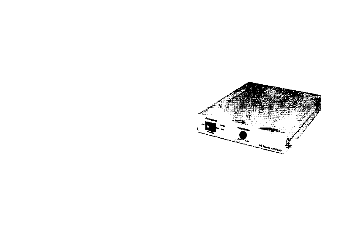
AC Adapter
AW-PS505
Panasonic
attempting io connect or operate ihie proouct.
please read these mstiucuons completely
Page 2

CAUTION
RISK OF ELSCTRIC SHXK
A
CAUTION:
TO REDUCE THE RISK OF ELECTRIC SHOCK, DO
NOT REMOVE COVER (OR BACK). NO USER SER
VICEABLE PARTS INSIDE.
REFER SERVICING TO QUAURED SERVICE PER
SONNEL.
The lightning flash with arrowhead sym
bol, within an equilateral triangle, is
intended to alert the user to the pres
ence of uninsulated "dangerous voltage"
A
SA 1965
A
SA 1966
within the product's enclosure that may
be of sufficient magnitude to constitute a
risk of electric shock to persons.
The exclamation point within an equilat
eral triangle is intended to alert the user
to the presence of important operating
and maintenance (servicing) instructions
in the literature accompanying the appli
ance.
-------------------------------------------------------------------------------------For U.S.A._-,
Warning:
This equipment generates and uses radio frequency ener
gy and if not installed and used properly, i.e., in strict
accordance with the instruction manual, may cause harmful
interference to radio communications. It has been tested
and found to comply with the limits for a Class A computing
device pursuant to Subpart J of Part 15 of FCC Rules,
which are designed to provide reasonable protection
against such interference when operated in a commercial
environment.
i________________________________________________________________________________________________ t
---------------------------------------------------------------------------------For CANADA --,
This digital apparatus does not exceed the Class A limits for
radio noise emissions from digital apparatus set out in the
Radio Interference Regulations of the Canadian Department
of Communications.
The serial number of this product may be found on the bot
tom of the unit.
You should note the serial number of this unit in the space
provided and retain this book as a permanent record of your
purchase to aid identification in the event of theft.
Model No._________________________________________
Serial No.--------------------------------------------------------------------
WARNING:
TO PREVENT FIRE OR ELECTRIC SHOCK HAZARD, DO NOT EXPOSE THIS APPLIANCE TO RAIN OR MOISTURE.
Page 3

CONTENTS
FEATURES ................................................................................................................................................................................ 1
PRECAUTIONS ............................................................................................................................................................................ 2
MAJOR OPERATING CONTROLS AND THEIR FUNCTIONS .................................................................................................... 3
CONNECTION............................................................................................................................................................................... 5
SPECIFICATIONS....................................................................................................................................;
ACCESORIES ................................................................................................................................................................................6
....................................
FEATURES
This is the AC adapter for the Multiport Hub AW-HB505.
6
-1-
Page 4

PRECAUTIONS
• Handle the control panel with care.
Dropping the control panel or subjecting it to a strong
shock can cause a failure or an accident.
• Operating temperature range -10“C to +45X
Avoid using it in a cold place below -10®C or a hot
place above +45°C because low or high temperature
will adversely affect the parts inside.
• Switch.power off before power cable connection or
disconnection.
Be sure to switch power off before connecting or dis
connecting the power cable.
• Avoid outdoor use.
• Install the control panel more than 1 meter away
from the monitors.
Care
Pull out the power cable plug, and wipe the control
panel clean with a dry cloth. If it is extremely dirty, dip
a cloth into a diluted solution of kitchen detergent,
squeeze it hard, and wipe the product surfaces care
fully.
— Note
• Do not use benzine, paint thinner, or other volatile
liquids.
• When using a chemical duster, carefully read the
caution notes on its use.
-2-
Page 5

MAJOR OPERATING CONTROLS AND THEIR FUNCTIONS
FRONT PANEL
O Power Switch [POWER ON/OFF]
Power is switched on to supply power to the Multiport
Hub when this switch is pressed to the ON position
(POWER Indicator lights), and is switched off when the
switch is pressed to the OFF position.
0 Power Indicator [POWER]
Lights red when POWER ON/OFF Switch O is pressed
to the ON position, and goes out when POWER
ON/OFF Switch O is pressed back to the OFF position.
e Fuse [FUSE (POWER)]
Power fuse. Use a 125 V, 3.15 A fuse to replace it.
-3-
Page 6

REAR PANEL
O AC 120V Input Connector [AC INj |AC 3P inlet)
Connect the supplied AC cable to it.
0 DC+12V Output Connector [DC 12V OUT]
(4P Cannon Connector)
Connect it to the DC 12V IN Connector on the Multiport
Hub with the supplied DC cable.
-A-
Page 7

CONNECTION
• Switch off all the devices before making any connection.
• Connect DC 12V OUT Connector 0 of this adapter to the DC +12V Input Connector on the Multiport Hub AW-HB505 with
the supplied DC cable.
• Connect the supplied AC cable to the AC 120V Inlet. Plug the AC cable to an AC outlet, and press POWER ON/OFF
Switch 0 of this adapter to the ON position.
Connecting the Adapter AW-PS505 to the Multiport Hub AW-HB505.
Multiport Hub {AW-HB505)
QO Odbl0
' (supplied)
Page 8

SPECIFICATIONS
Power:
IPower Output:
Operating temperature:
Dimensions:
Weight:
Finish:
Weight and dimensions indicated are approximate.
Specifications are subject to change without notice.
120 VAC 60 HZ0.44A
DC12V 2.5A, with over-current protect circuit
-1 O^C to +45°C {14°F to 113°F)
210(W) X 51(H) X 250(D) mm
8-1/4”(W) X 2"(H) X 9-7/8"(D)
2.5 kg (5,5 lbs.)
AV Ivory baking
ÀCCESORIES
AC Cable ..................................................................1 pC.
DC Cable ..................................................................1 pc.
-6-
 Loading...