

Page 1
Operating Instructions
<Operations and Settings>
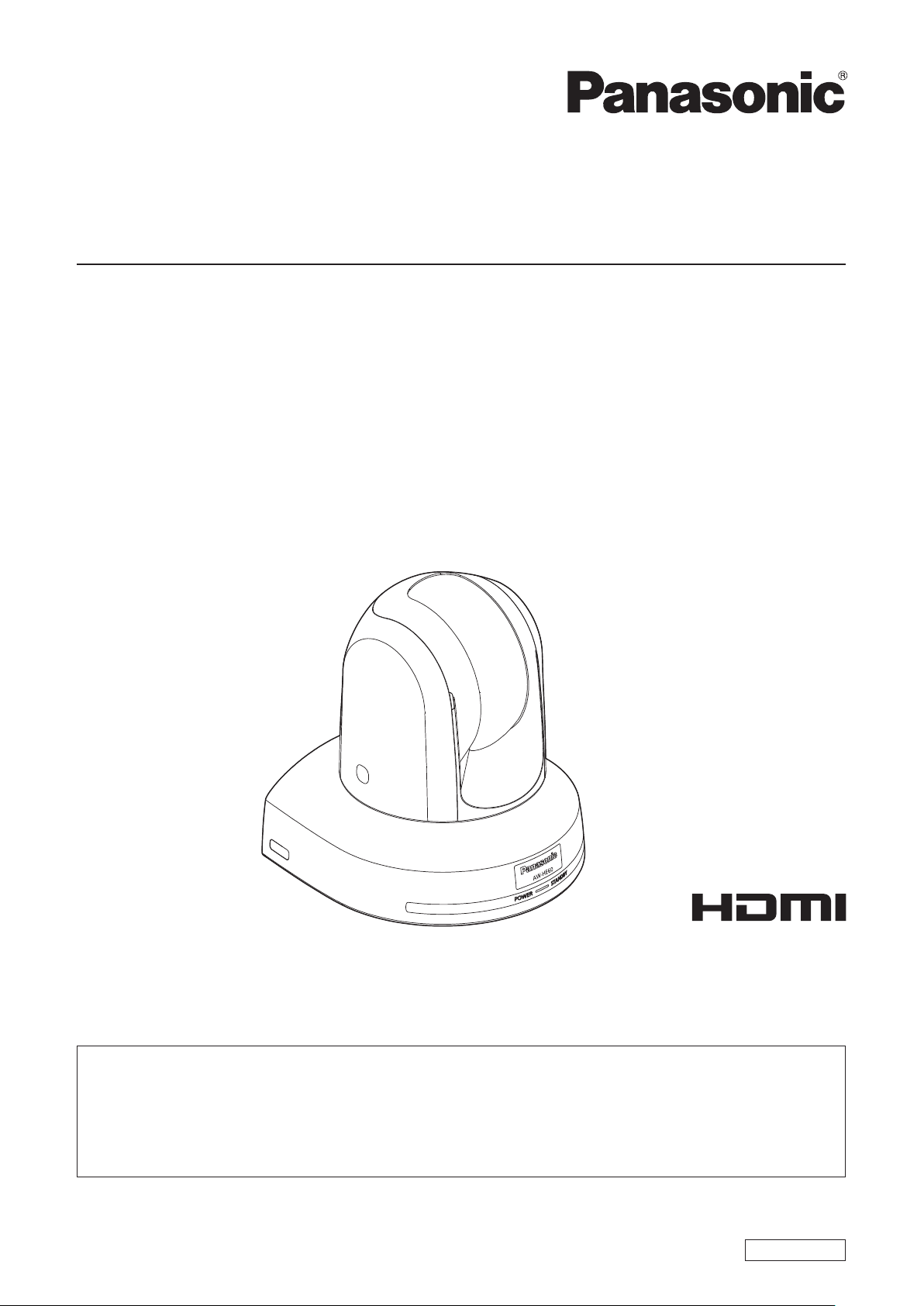
HD Integrated Camera
Model No.
Model No.
Model No.
Model No.
AW‑HE60HN
AW‑HE60SN
AW‑HE60HE
AW‑HE60SE
HowtheOperatingInstructionsareconfigured
<Basics>:
The <Basics> describes the procedure for basic operation and installation. Before installing this unit, be
sure to take the time to read through <Basics> to ensure that the unit will be installed correctly.
<Operations and Settings> (this manual):
This <Operations and Settings> describes how to operate the unit and how to establish its settings.
ENGLISH
VQT4M09A(E)M0712MS0 -FJ
Page 2
Trademarks and registered trademarks
Abbreviations
p Microsoft®, Windows®, Windows® 7, Internet Explorer®,
ActiveX
®
and DirectX® are either registered trademarks or
trademarks of Microsoft Corporation in the United States
and other countries.
®
p Intel
and Intel® CoreTM are trademarks or registered
trademarks of Intel Corporation in the United States and
other countries.
p Adobe
®
and Reader® are either registered trademarks or
trademarks of Adobe Systems Incorporated in the United
States and/or other countries.
p HDMI, the HDMI logo and High-Definition Multimedia
Interface are the trademarks or registered trademarks
of HDMI Licensing, LLC in the United States and other
countries.
p Apple, Mac, Mac OS, iPhone, iPod Touch, iPad, and Safari
are registered trademarks of Apple Inc., in the United
States and other countries.
p Android
TM
is a trademark of Google Inc.
p Other names of companies and products contained
in these Operating Instructions may be trademarks or
registered trademarks of their respective owners.
About copyright and licence
Distributing, copying, disassembling, reverse compiling,
reverse engineering, and also exporting in violation of export
laws of the software provided with this unit are expressly
prohibited.
The following abbreviations are used in this manual.
p Microsoft
®
Windows® 7 Professional SP1 32/64-bit is
abbreviated to “Windows 7”.
p Microsoft
Windows
®
Windows® XP Professional SP3 and Microsoft®
®
XP Home Edition SP3 are abbreviated to
“Windows XP”.
p Windows
Explorer
®
Internet Explorer® 8.0 and Windows® Internet
®
9.0 are abbreviated to “Internet Explorer”.
For the purposes of this manual, the model numbers of the
units are given as listed in the table below.
Model number
of unit
AW-HE60HN
AW-HE60HE
AW-HE60SN
AW-HE60SE
AW-HE60HN
AW-HE60HE
AW-HE60SN
AW-HE60SE
AW-HS50N
AW-HS50E
AW-PS550N
AW-PS550E
AW-RP50N
AW-RP50E
AW-RP555N
AW-RP555L
AW-RP655N
AW-RP655L
AW-CA20T6G AW‑CA20T6
Model number
given in manual
AW‑HE60
AW‑HE60H
AW‑HE60S
AW‑HS50
AW‑PS550
AW‑RP50
AW‑RP555
AW‑RP655
Illustrations and screen displays featured in the
manual
p What is shown in the manual’s illustrations and screen
displays may differ from how it is actually appears.
p Functions which can be used by Windows only are
indicated using the
mark.
2
Page 3

Contents
Before use ...........................................................................4
Overview ..........................................................................4
Required personal computer environment .......................4
Disclaimer of warranty......................................................5
Network security ..............................................................5
Concerning the plug-in viewer software ...........................6
Basic shooting operations ................................................7
How to turn the power on and off ..................................... 8
Turning the power on .......................................................8
Turning the power off .......................................................9
Selecting the units ............................................................10
Selecting the shooting modes (scene files) ................... 10
Types of shooting modes ...............................................10
How to select the shooting mode ...................................11
Shooting ............................................................................13
What to do when encountering problems
in the basic shooting operations ................................14
More advanced operations ..............................................15
Manual shooting ...............................................................16
Manually adjusting the focus .......................................... 16
Manually adjusting the iris .............................................. 17
Manually adjusting the shutter speed ............................18
Manually adjusting the gain ...........................................19
Preset memories ...............................................................20
White balance adjustment ............................................... 23
White balance adjustment .............................................. 23
Black level (master pedestal) adjustment ......................27
Black level (master pedestal) adjustment.......................27
Genlock adjustment (AW‑HE60S only) ........................... 29
Genlock adjustment .......................................................29
Camera menu items .........................................................40
Setting the camera menu items .....................................40
Top Menu screen ...........................................................40
Camera screen (when FullAuto is selected) ..................41
Camera screen (when Manual1 to 3 is selected) ........... 41
Contrast screen .............................................................. 42
Picture 1/2 screen ..........................................................43
Picture 2/2 screen ..........................................................44
16-axis color matrix ........................................................45
System screen ...............................................................46
Genlock screen (AW-HE60S only) .................................46
Output screen ................................................................47
Other 1/2 screen ............................................................ 49
Other 2/2 screen ............................................................ 50
Maintenance screen ....................................................... 51
Firmware Version screen ...............................................51
IP Network screen .......................................................... 52
Camera menu item table ..................................................53
Controls and settings from web screen .........................55
Displaying the web screen
using a personal computer ........................................ 56
Live screen: Single display mode ...................................58
Live screen: Multi display mode ..................................... 63
Setup screen ..................................................................64
Displaying the web screen using a mobile terminal .......96
System log displays .......................................................100
Limiters ............................................................................101
Setting/releasing the limiters ........................................102
Basic limiter operations ................................................102
Setting the limiters .......................................................102
Releasing the limiters ................................................... 103
Resetting the limiters ...................................................103
Basic operations ...............................................................32
When performing the operations
using the wireless remote control ..............................34
Control exercised from the Multi-Function
Controller AW-RP655 ................................................35
Control exercised from the Multi Hybrid
Control Panel AW-RP555 ..........................................37
Control exercised from the Remote
Camera Controller AW-RP50 .................................... 39
Safe mode .......................................................................104
Concerning the safe mode ...........................................104
®
Notes on Windows
System requirements for a personal computer ............105
Trademarks and Registered Trademarks .....................105
Precautions when using Windows 7 ............................106
Index ................................................................................ 111
7 .....................................................105
3
Page 4

Before use
pwOverview
p This unit is a compact full HD camera integrated with a
pan-tilt head and featuring a 1/3-type full HD MOS sensor
and digital signal processor (DSP).
p In addition to its optical 18 zoom lens, the unit comes
with a 10 digital zoom to achieve high-quality shooting
that overflows with ambiance.
p The unit features a night mode, making it possible to shoot
even under very-low-brightness conditions by exposing
subjects to infrared rays.
p Two models are available: the HDMI model AW-HE60H
which is ideal for distributing the signals of TV conference
and other video events, and the SDI output model
AW-HE60S which is ideal for creating content.
IP video transfer and IP control can be performed for both
models.
It is also possible to connect to an existing camera
controller using serial control.
pwRequired personal computer
environment
CPU Intel® CoreTM2 DUO 2.4 GHz or faster or
CPU with the equivalent specifications
Memory [When using Windows]
Network
function
Image display
function
Supported
operating
system and
Web browser
512 MB or more
(When using Microsoft
7: 1 GB [32 bits] or 2 GB [64 bits] or
more)
[When using Mac OS X]
2 GB or more
10Base-T or 100Base-TX port 1
Resolution: 1024 768 pixels or
Color generation: True Color 24 bits or
Microsoft
SP1 64-bit*
Microsoft® Windows® 7 Professional
SP1 32-bit*
®
Windows® 7 Professional
1
1
Windows® Internet Explorer® 8.0*
Windows® Internet Explorer® 9.0*
more
more
®
Windows®
2
2
Microsoft® Windows® XP Home Edition
3
SP3*
Microsoft® Windows® XP Professional
Edition SP3*
Apple
Mac OS X v10.5
Safari 5.0.6
Apple
Mac OS X v10.6
Safari 5.1.5
Apple
Mac OS X v10.7
Safari 5.1.5
*1: This cannot be used in the
Windows
3
®
*2: This cannot be used with the 64-bit
version of Internet Explorer
*3: The Microsoft
Professional x64 Edition is not
supported.
Other CD-ROM drive
(for using the Operating Instructions and
various software)
®
DirectX
Adobe
9.0c and up
®
Reader
(for browsing the Operating Instructions
on the CD-ROM)
XP compatibility mode.
®
8.0.
®
Windows® XP
®
4
Page 5
Before use
(continued)
IMPORTANT
p Failure to provide the required personal computer
environment may slow down the delineation of
the images on the screen, make it impossible for
the web browser to work and cause other kinds of
problems.
p When using Microsoft® Windows® 7, refer to the “Notes on
Windows
environment that is required and on the precautions and
other items.
®
7” (page 105) for details on the personal computer
pwDisclaimer of warranty
IN NO EVENT SHALL Panasonic Corporation BE LIABLE
TO ANY PARTY OR ANY PERSON, EXCEPT FOR
REPLACEMENT OR REASONABLE MAINTENANCE OF
THE PRODUCT, FOR THE CASES, INCLUDING BUT NOT
LIMITED TO BELOW:
1 ANY DAMAGE AND LOSS, INCLUDING WITHOUT
LIMITATION, DIRECT OR INDIRECT, SPECIAL,
CONSEQUENTIAL OR EXEMPLARY, ARISING OUT
OF OR RELATING TO THE PRODUCT;
2 PERSONAL INJURY OR ANY DAMAGE CAUSED BY
INAPPROPRIATE USE OR NEGLIGENT OPERATION
OF THE USER;
3 UNAUTHORIZED DISASSEMBLE, REPAIR OR
MODIFICATION OF THE PRODUCT BY THE USER;
4 INCONVENIENCE OR ANY LOSS ARISING WHEN
IMAGES ARE NOT DISPLAYED, DUE TO ANY
REASON OR CAUSE INCLUDING ANY FAILURE OR
PROBLEM OF THE PRODUCT;
5 ANY PROBLEM, CONSEQUENTIAL
INCONVENIENCE, OR LOSS OR DAMAGE, ARISING
OUT OF THE SYSTEM COMBINED BY THE DEVICES
OF THIRD PARTY;
6 ANY DEMANDS FOR COMPENSATION, CLAIMS,
ETC. OCCASIONED BY THE INFRINGEMENT OF
PRIVACY BY INDIVIDUALS OR ORGANIZATIONS
WHOSE IMAGES WERE SHOT BY THE USER
BECAUSE THESE IMAGES (INCLUDING THE
RECORDINGS MADE) WERE MADE AVAILABLE
BY THE USER BECAUSE IN THE PUBLIC DOMAIN
FOR SOME REASON OR OTHER OR BECAUSE THE
IMAGES ENDED UP BEING USED FOR PURPOSES
OTHER THAN THE ONE DESCRIBED ABOVE;
7 LOSS OF REGISTERED DATA CAUSED BY ANY
FAILURE.
pwNetwork security
As you will use this unit connected to a network, your
attention is called to the following security risks.
1 Leakage or theft of information through this unit
2 Use of this unit for illegal operations by persons with
malicious intent
3 Interference with or stoppage of this unit by persons
with malicious intent
It is your responsibility to take precautions such as those
described below to protect yourself against the above
network security risks.
p Use this unit in a network secured by a firewall, etc.
p If this unit is connected to a network that includes
personal computers, make sure that the system is not
infected by computer viruses or other malicious entities
(using a regularly updated antivirus program, anti-spyware
program, etc.).
p Protect your network against unauthorized access by
restricting users to those who log in with an authorized
user name and password.
p Apply measures such as user authentication to protect
your network against leakage or theft of information,
including image data and authentication information (user
names and passwords).
p Do not install the camera in locations where the camera or
the cables can be destroyed or damaged by persons with
malicious intent.
Usage restrictions
Use of the same segment is recommended for the network
in which the unit and the controller or personal computer are
connected.
If the equipment uses connections with different segments,
events based on the settings inherent to the network
equipment, for instance, may occur so check this thoroughly
prior to operation.
5
Page 6
Before use
(continued)
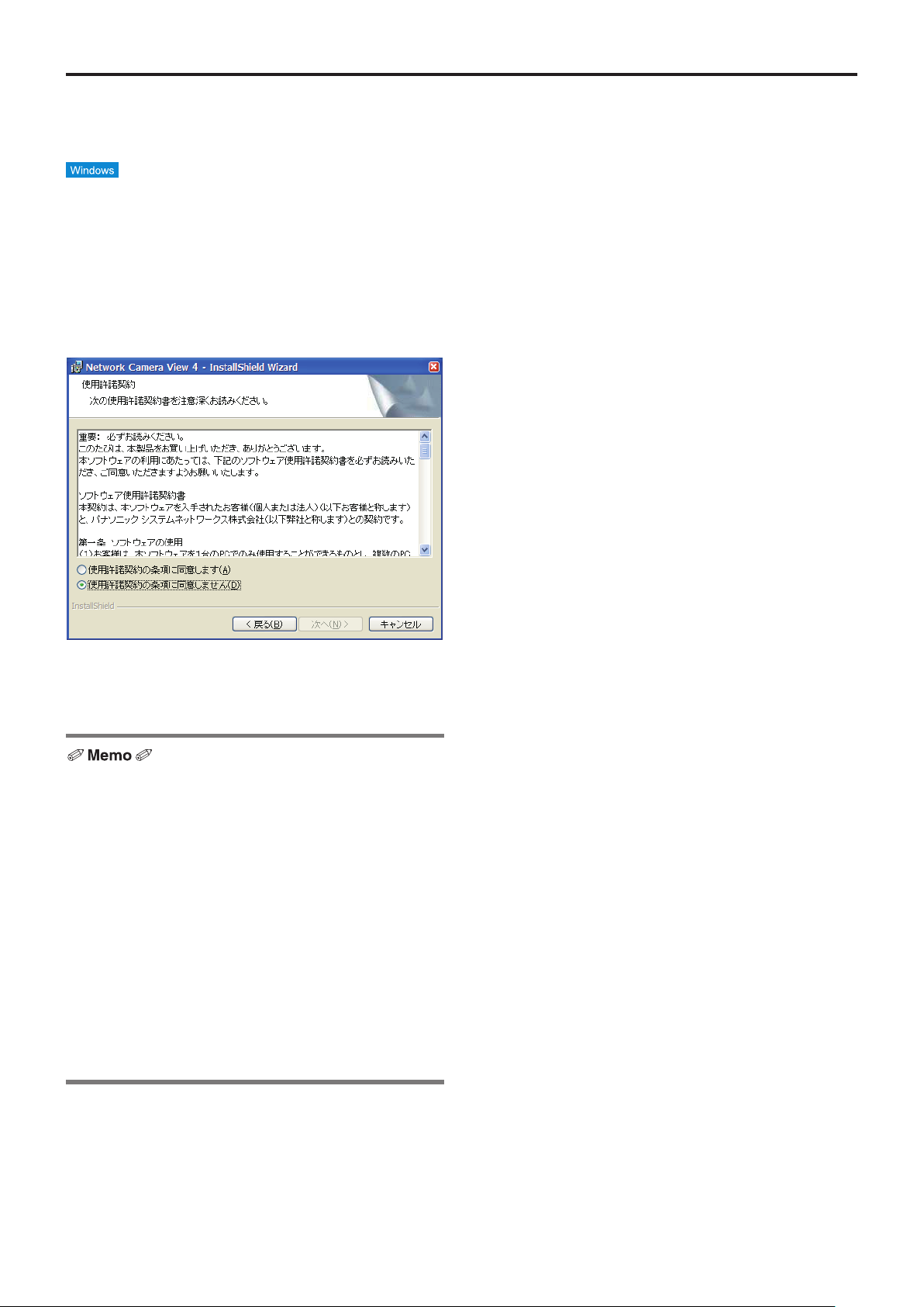
pwConcerning the plug‑in viewer
software
p This is necessary only when using a personal computer
running Windows.
In order to display the IP videos on this unit, the “Network
Camera View4” plug-in viewer software must be installed.
Either install the software directly from the unit or click the
[Install] button of the “plug-in viewer software” on the menu of
the CD-ROM supplies, and follow the on-screen instructions
to install the software.
英語版
要入手
p When the unit is purchased, “Automatic installation
of viewer software” is set to “On”. Refer to page 65 if a
message appears on the information bar of the browser.
p When a Live screen is first displayed from the personal
computer, the screen on which to install ActiveX required
to display the camera images appears. Follow the
on-screen instructions to install the software.
p If the installation screen is displayed every time the screen
is switched even after ActiveX has been installed, reboot
the personal computer.
p A license to use the plug-in viewer software is required
for every personal computer which uses the software.
The number of times the plug-in software has been
automatically installed can be checked on the “Product
info. screen” (page 92) under “Maintenance” (page 91).
Consult the dealer from whom you purchased the unit
concerning these licenses.
6
Page 7

Basic shooting operations
1 Set the subject brightness to the appropriate
level.
2 Turn on the power of all the units and devices
in the system.
3 Select the unit to be operated.
Even when using only one unit, it must still be selected
from the wireless remote control or controller.
4 Select the shooting mode.
Select one of the four (FullAuto, Manual1, Manual2 and
Manual3) preset shooting modes (scene files), each of
which corresponds to a set of circumstances in which
the subject will be shot.
Select the mode that satisfies the shooting conditions
and suits your preferences.
When continuing to shoot in the same circumstances,
there is no need to select another mode.
5 Start shooting.
(After shooting, turn off the power of all the
units and devices in the system.)
With the basic operations, it is assumed that the focus, iris
and white balance will be adjusted automatically (as per the
factory settings).
If the settings have already been changed and the original
settings are to be restored, refer to the “What to do when
encountering problems in the basic shooting operations”
(page 14) and “Camera screen” (page 41) in “Camera menu
items”.
Note
p If “FullAuto” has been selected as the setting
for Scene on the camera menu, for example, all
the auto settings will be turned on, and manual
operations will no longer be possible for some of
the items.
7
Page 8

How to turn the power on and off
pwTurning the power on
When performing the operations
using the wireless remote control
1 Set all the power switches of the units and
devices connected in the system to ON.
p This unit does not have a power switch.
When power is supplied to it, the status display lamp
will light up orange.
The initial operation is then performed, and after this
the unit is set to the standby mode.
2 Press one of the [CAM1] to [CAM4] buttons on
the wireless remote control to select the unit.
3 Press the [ON/STANDBY] button on the
wireless remote control for 2 seconds.
The POWER ON mode is established, images are
output, and control can be exercised.
p The unit’s status display lamp now lights up green.
Notes
p It takes about 30 seconds per unit for the initial
settings operation to be completed. During this
period, the unit cannot be operated.
(Status display lamp: light up orange)
p When transferring to the STAND BY mode
(Status display lamp: Orange)
The pan/tilt position is stored in the memory, and
the pan/tilt unit is moved so that it points backwards.
p When transferring to the POWER ON mode
(Status display lamp: Green (after the initial setting
operation is completed))
The pan/tilt unit is moved to the position which was
stored in the memory when the transition to the
STAND BY mode was made.
p POWER ON preset
The pan/tilt unit is moved to the setting, which was
established immediately prior to the transition to the
STAND BY mode, when the power has been turned
on.
p If the power is turned off without transferring to the
STAND BY mode, the pan/tilt unit position will not
be stored in the memory or reflected in the POWER
ON preset. The zoom position is stored using the
setting established immediately before the power is
turned off.
When performing the operations using the controller
When the AW‑RP655 or AW‑RP555 is connected:
1 Set all the power switches of the units and
devices connected in the system to ON.
p This unit does not have a power switch.
When power is supplied to it, the status display lamp
will light up orange.
The initial operation is then performed, and after this
the unit is set to the standby mode.
2 Set the [OPERATE] switch on the controller to
ON.
The POWER ON mode is established, images are
output, and control can be exercised.
p The unit’s status display lamp now lights up green.
Notes
p It takes about 30 seconds per unit for the initial
settings operation to be completed. During this
period, the unit cannot be operated.
(Status display lamp: light up orange)
p When transferring to the STAND BY mode
(Status display lamp: Orange)
The pan/tilt position is stored in the memory, and
the pan/tilt unit is moved so that it points backwards.
p When transferring to the POWER ON mode
(Status display lamp: Green (after the initial setting
operation is completed))
The pan/tilt unit is moved to the position which was
stored in the memory when the transition to the
STAND BY mode was made.
p POWER ON preset
The pan/tilt unit is moved to the setting, which was
established immediately prior to the transition to the
STAND BY mode, when the power has been turned
on.
p If the power is turned off without transferring to the
STAND BY mode, the pan/tilt unit position will not
be stored in the memory or reflected in the POWER
ON preset. The zoom position is stored using the
setting established immediately before the power is
turned off.
Before setting the [OPERATE] switch on the controller to ON,
be absolutely sure to set all the power switches of the units
and devices connected in the system to ON.
4 If a multiple number of units are going to be
used, repeat steps
The unit’s status display lamp blinks green when a signal
matched by the remote control ID has been received, and
it blinks orange when a signal that is not matched by the
remote control ID has been received.
8
2 and 3 as required.
For further details, refer to the Operating Instructions of the
controller.
When the AW‑RP50 is connected:
Refer to the Operating Instructions of the controller.
Page 9

How to turn the power on and off
(continued)
pwTurning the power off
When performing the operations
using the wireless remote control
1 Press one of the [CAM1] to [CAM4] buttons on
the wireless remote control to select the unit.
2 Press the [ON/STANDBY] button on the
wireless remote control for 2 seconds.
The unit’s power is turned off.
p The unit’s status display lamp now lights up orange.
3 If a multiple number of units are going to be
used, repeat steps
1 and 2 as required.
4 Set all the power switches of the units and
devices connected in the system to OFF.
Notes
p When transferring to the STAND BY mode
(Status display lamp: Orange)
The pan/tilt position is stored in the memory, and
the pan/tilt unit is moved so that it points backwards.
p When transferring to the POWER ON mode
(Status display lamp: Green (after the initial setting
operation is completed))
The pan/tilt unit is moved to the position which was
stored in the memory when the transition to the
STAND BY mode was made.
p POWER ON preset
The pan/tilt unit is moved to the setting, which was
established immediately prior to the transition to the
STAND BY mode, when the power has been turned
on.
p If the power is turned off without transferring to the
STAND BY mode, the pan/tilt unit position will not
be stored in the memory or reflected in the POWER
ON preset. The zoom position is stored using the
setting established immediately before the power is
turned off.
When performing the operations using the controller
When the AW‑RP655 or AW‑RP555 is connected:
1 Set the [OPERATE] switch on the controller to
OFF.
The power of all the cameras (including the unit)
connected to the controller is turned off.
p The unit’s status display lamp now lights up orange.
2 Set all the power switches of the units and
devices connected in the system to OFF.
Notes
p When transferring to the STAND BY mode
(Status display lamp: Orange)
The pan/tilt position is stored in the memory, and
the pan/tilt unit is moved so that it points backwards.
p When transferring to the POWER ON mode
(Status display lamp: Green (after the initial setting
operation is completed))
The pan/tilt unit is moved to the position which was
stored in the memory when the transition to the
STAND BY mode was made.
p POWER ON preset
The pan/tilt unit is moved to the setting, which was
established immediately prior to the transition to the
STAND BY mode, when the power has been turned
on.
p If the power is turned off without transferring to the
STAND BY mode, the pan/tilt unit position will not
be stored in the memory or reflected in the POWER
ON preset. The zoom position is stored using the
setting established immediately before the power is
turned off.
For further details, refer to the Operating Instructions of the
controller.
When the AW‑RP50 is connected:
Refer to the Operating Instructions of the controller.
9
Page 10

Selecting the units
Up to four units can be operated using one wireless remote
control.
Up to five units and devices can be operated using one
controller.
Select the unit (or units) to be operated from the wireless
remote control or controller.
Even when using only one unit, it must still be selected.
When performing the operations
using the wireless remote control
1 Press the [CAM1], [CAM2], [CAM3] or [CAM4]
button.
The unit’s status display lamp blinks green when a signal
matched by the remote control ID has been received,
and it blinks orange when a signal that is not matched by
the remote control ID has been received.
When performing the operations using the controller
When the AW‑RP655 is connected:
1 Press the [1], [2], [3], [4] or [5] button of
[CONTROL/PREVIEW MONITOR OUT SEL].
When the AW‑RP555 is connected:
1 Press the [1], [2], [3], [4] or [5] button of
[CONTROL].
When the AW‑RP50 is connected:
Refer to the Operating Instructions of the controller.
Selecting the shooting modes (scene files)
pwTypes of shooting modes
This unit has four preset shooting modes, each of which
corresponds to a set of circumstances in which the subject
will be shot.
Select the mode that satisfies the shooting conditions and
suits your preferences.
The settings can be changed by menu operations.
p The results of the white balance and other adjustments
are stored in the memory separately by shooting mode.
Be absolutely sure to select the shooting mode before
making any adjustments.
Note
p If “FullAuto” has been selected as the setting
for Scene on the camera menu, for example, all
the auto settings will be turned on, and manual
operations will no longer be possible for some of
the items.
FullAuto
The shutter speed and lens iris setting are adjusted
automatically.
Manual1
The settings of your preferences can be established
in line with the shooting scene, lighting and other
conditions.
Manual2
The settings of your preferences can be established
in line with the shooting scene, lighting and other
conditions.
Manual3
The settings of your preferences can be established
in line with the shooting scene, lighting and other
conditions.
10
Page 11
Selecting the shooting modes (scene files)
(continued)
pwHow to select the shooting
mode
When performing the operations
using the wireless remote control
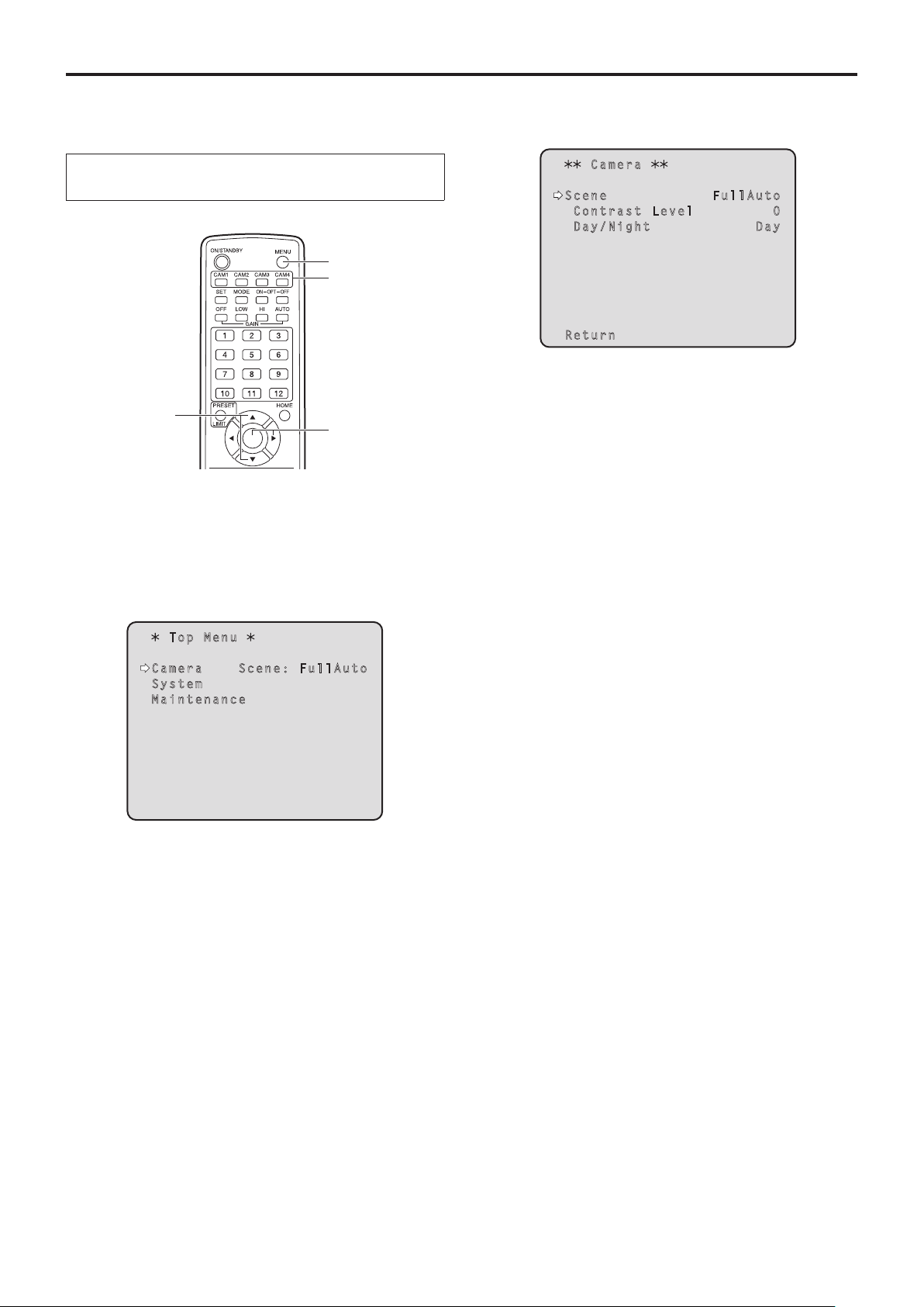
2, 8
1
3, 5, 7
4, 6, 7
1 Press the [CAM1], [CAM2], [CAM3] or [CAM4]
button to select the unit.
2 Press the [MENU] button for 2 seconds.
The Top Menu is displayed.
4 Press the [] button.
The “Camera” sub-menu is displayed on the monitor.
C a m e r a
Scen e F ul l A ut o
Con t r a s t L e v e l 0
Day / N i g h t Da y
Retu r n
5 Press the [] or [] button to bring the cursor
to “Scene”.
6 Press the [] button.
The shooting mode blinks.
7 Press the [] or [] button to select the
shooting mode (FullAuto, Manual1, Manual2 or
Manual3) to be used, and press the [] button
to enter the selection.
Top M e n u
Camer a S c e n e : F ul l A ut o
Syste m
Maint e n a n c e
3 Press the [] or [] button to bring the cursor
to “Camera”.
8 Press the [MENU] button for 2 seconds.
The camera menu display is exited.
11
Page 12
Selecting the shooting modes (scene files)
(continued)
When performing the operations using the controller
When the AW‑RP655 is connected:
1 Press one of the [1] to [5] buttons of
[CONTROL/PREVIEW MONITOR OUT SEL] to
select the unit which is to be operated.
2 Press the [MENU] button to set the LCD panel
display to the menu mode.
3 Turn the jog dial (main) until CAMERA SETTING
appears, and press the [OK] button.
CAMERA SETTING
OK Key
4 When the scene selection menu has appeared
on the LCD panel, select the scene to be set,
and press the [OK] button.
When the AW‑RP555 is connected:
1 Press the [1], [2], [3], [4] or [5] button of
[CONTROL] to select the unit.
2 Press the [1], [2], [3] or [USER] button of
[SCENE FILE] to select the shooting mode.
Shooting mode [SCENE FILE] button
Manual1 [1]
Manual2 [2]
Manual3 [3]
FullAuto [USER]
When the AW‑RP50 is connected:
Refer to the Operating Instructions of the controller.
SCENE HALOGEN
OK Key
The scene names displayed on the LCD panel correlate
with the scene files of the AW-HE60 as shown below.
AW‑RP655 display AW‑HE60 scene file
HALOGEN Manual1
FLUORESCENT Manual2
OUTDOOR Manual3
USER FullAuto
5 When the following message appears on the
LCD panel, press the [MENU] button twice to
exit the menu mode.
OPEN CAMERA MENU ?
OK Key
12
Page 13
Shooting
When performing the operations
using the wireless remote control
pqChanging the camera’s direction
Moving the camera toward the left or right (panning):
Press the [] or [] button.
Moving the camera up or down (tilting):
Press the [] or [] button.
Moving the camera diagonally:
Press the [] or [] button and [] or [] button at
the same time.
Returning the camera to the reference position:
Press the [HOME] button for 2 seconds.
pqUsing the zoom function
Zooming in (the subject becomes magnified in size):
Press the [T] button of [ZOOM].
Zooming out (the subject becomes reduced in size):
Press the [W] button of [ZOOM].
pqSwitching the direction or zoom speed
Changing the direction or zoom at high speed:
Press the [FAST] button.
When this button is held down, the speed can be set to
an even higher speed.
When it is tapped, the normal speed (high speed) is
restored.
Changing the direction or zoom at low speed:
Press the [SLOW] button.
When this button is held down, the speed can be set to
an even lower speed.
When it is tapped, the normal speed (low speed) is
restored.
The lens focus control speed is also changed at the same
time.
When performing the operations using the controller
pqChanging the camera’s direction
Moving the camera toward the left or right (panning):
Tilt the [PAN/TILT] lever toward L or R.
Moving the camera up or down (tilting):
Tilt the [PAN/TILT] lever toward UP or DOWN.
Moving the camera diagonally:
Tilt the [PAN/TILT] lever diagonally.
Returning the camera to the reference position:
If the controller has a [HOME] button, press the
[HOME] button.
pqUsing the zoom function
Zooming in (the subject becomes magnified in size):
Tilt the [ZOOM] lever toward the TELE direction.
Zooming out (the subject becomes reduced in size):
Tilt the [ZOOM] lever toward the WIDE direction.
Note
p The indicator displays of the AW-RP655 are
indicators that show the positions of the optical
zoom. They will not work for electronic zooming.
pqChanging the direction or zoom speed
AW‑RP655 and AW‑RP555
1 Press the [SPEED] button.
Each time the [SPEED] button is pressed, the control
speed is switched between the high speed (the button’s
lamp is off) and low speed (the button’s lamp is lighted).
The lens focus control speed is also changed at the
same time.
AW‑RP50
Refer to the Operating Instructions of the controller.
13
Page 14

What to do when encountering problems in the basic shooting operations
If the trouble is not resolved by taking the action suggested
below, refer to “Troubleshooting” (page 43 in the <Basics>).
When performing the operations
using the wireless remote control
The unit does not move.
p Press the [CAM1], [CAM2], [CAM3] or [CAM4] button to
select the unit which is to be operated.
If only one unit is being used, it is normally selected using
the [CAM1] button.
p Check that the IR ID switches have been set correctly.
(Refer to pages 37 and 40 in the <Basics>.)
p If the unit’s status display lamp is off or lights up orange, it
means that the unit’s power is not on.
Refer to “Turning the power on” (page 8), and turn on the
power.
p If the unit’s status display lamp does not blink even when
the wireless remote control is operated near the unit’s
wireless remote control signal light-sensing area, it means
that the wireless remote control’s batteries have run down.
Replace the batteries.
Multiple color bands (color bars) are displayed.
Press the [MODE] button to switch to the camera picture.
When performing the operations using the controller
The unit does not move.
p Select the unit to be operated by following the procedure
below.
When the AW‑RP655 is connected:
Press the [1], [2], [3], [4] or [5] button of [CONTROL/
PREVIEW MONITOR OUT SEL].
When the AW‑RP555 is connected:
Press the [1], [2], [3], [4] or [5] button of [CONTROL].
When the AW‑RP50 is connected:
Refer to the Operating Instructions of the controller.
p If the [OPERATE] lamp on the controller is off, it means
that the power of the controller is not on.
p If the unit’s status display lamp is off or lights up orange, it
means that the unit’s power is not on.
Refer to “Turning the power on” (page 8), and turn on the
power.
The menu screen is displayed.
Press the [MENU] button for 2 seconds to exit the camera
menu.
The lens focus is not adjusted automatically.
Press the [A/FOCUS] button to switch to auto focusing.
(Auto focusing does not work during panning or tilting
operations.)
The camera picture is too light or too dark.
1. Press the [A/IRIS] button to switch the lens iris
adjustment to auto.
2. Press the [AUTO] button of [GAIN] to switch the gain
adjustment to auto.
Something is wrong with the coloring of the
camera pictures.
Refer to “Auto tracking white adjustment (ATW)” (page 25), and
switch to “ATW”.
The camera menus are not displayed.
When color bar signals are output, the camera menus are
not displayed with composite signals.
To operate the camera menus with composite signals, set the
color bar display to OFF.
Multiple color bands (color bars) are displayed.
Press the [MODE] button to switch to the camera picture.
The menu screen is displayed.
Press the [MENU] button to exit the camera menu.
The lens focus is not adjusted automatically.
Press the [EXT(AF)] button to switch to auto focusing.
(Auto focusing does not work during panning or tilting
operations.)
The camera picture is too light or too dark.
1. Press the [IRIS] button several times to turn on its lamp,
and switch the lens iris adjustment to auto.
2. Press the [GAIN] button several times to turn on its lamp,
and switch the gain adjustment to auto.
Something is wrong with the coloring of the
camera pictures.
Refer to “Auto tracking white adjustment (ATW)” (page 25), and
switch to “ATW”.
The camera menus are not displayed.
When color bar signals are output, the camera menus are
not displayed with composite signals.
To operate the camera menus with composite signals, set the
color bar display to OFF.
14
Page 15

More advanced operations
Manual shooting (see pages 16 to 19)
p Manual adjustment of focus
p Manual adjustment of iris
p Manual adjustment of shutter speed
p Manual adjustment of gain
Preset memories (see pages 20 to 22)
p Up to 100 settings for the camera direction (panning and
tilting), zoom, focus, iris, gain up and white balance can be
registered in the preset memories, and called.
p The number of settings that can be registered and
called depends on the type of wireless remote control
(12 settings) or controller that is used for operation.
White balance adjustment
(see pages 23 to 26)
p This adjustment is performed to express the white
accurately. Its setting also has an effect on the color tones
of the entire screen.
p It must be performed when using the unit for the first
time or when the unit has not been used for a prolonged
period.
p It must be performed when the lighting conditions or
brightness has changed.
p Once the white balance has been attained, no further
adjustment is required provided that the unit is going to be
used under the same conditions.
Black level (master pedestal) adjustment
(see pages 27 to 28)
p This adjustment is performed to align the black level
(pedestal level) of a multiple number of cameras.
p Ask your dealer to perform this adjustment.
Genlock adjustment (AW‑HE60S only)
(see pages 29 to 31)
p This adjustment is performed to achieve phase alignment
by applying external synchronization (genlock) when a
multiple number of cameras will be used or when the unit
will be used in combination with other devices.
p Ask your dealer to perform this adjustment.
15
Page 16

Manual shooting
pwManually adjusting the focus
The lens focus can be adjusted manually.
When performing the operations
using the wireless remote control
1 Press the [M/FOCUS] button to switch the
focus to manual adjustment.
2 Press the [F] or [N] button of [FOCUS] to adjust
the focus.
When the [F] button is pressed, the focus moves further
away (far); conversely, when the [N] button is pressed, it
moves nearer (near).
The speed of focusing and other adjustments can
be switched to fast or slow by pressing the [FAST] or
[SLOW] button, respectively.
3 If necessary, press the [A/FOCUS] button to
return the focus to the automatic adjustment.
When performing the operations using the controller
When the AW‑RP655 is connected:
1 Press the [EXT(AF)] button to switch the focus
to manual adjustment.
When the AW‑RP555 is connected:
1 Press the [(AF)EXT] button to switch the focus
to manual adjustment.
2 Adjust the focus manually by tilting the
[FOCUS] lever.
Furthermore, every time the [SPEED] button is pressed,
the speed of the focusing and other adjustments can be
switched to fast or slow.
3 If necessary, press the [(AF)EXT] button to
return the focus to the automatic adjustment.
When the AW‑RP50 is connected:
Refer to the Operating Instructions of the controller.
Note
p When the focus is set to manual, the subject may
go out of focus during panning, tilting and zooming.
Therefore, the unit comes with a function which
compensates for this. (Focus compensation during
zooming function: Focus ADJ With PTZ.)
This function was set to ON at the factory.
If the function has been set to OFF, either adjust the
focus, as required, after zooming or set the focus to
auto. (See page 49 and page 81.)
2 Adjust the focus manually by turning the dial
above the lit [FOCUS] lamp whether it is the
lamp of the [PAN/TILT] lever or [ZOOM] lever.
Furthermore, every time the [SPEED] button is pressed,
the speed of the focusing and other adjustments can be
switched to fast or slow.
3 If necessary, press the [EXT(AF)] button to
return the focus to the automatic adjustment.
16
Page 17
Manual shooting
(continued)
pwManually adjusting the iris
The lens iris can be adjusted manually.
When performing the operations
using the wireless remote control
1 Press the [M/IRIS] button to switch the iris to
manual adjustment.
2 Adjust the iris using the [IRIS +] or [IRIS –]
button.
Press the [IRIS +] button to adjust the lens iris in the
opening direction; conversely, press the [IRIS –] button to
adjust the lens iris in the closing direction.
3 If necessary, press the [A/IRIS] button to return
the iris to the automatic adjustment.
When the AW‑RP555 is connected:
1 Press the [IRIS] button to turn off its lamp and
switch to manual adjustment.
2 Turn the [LEVEL] dial of [IRIS] to adjust the iris
manually.
The position of the [LEVEL] dial does not represent an
absolute value.
This is why the brightness may differ from one camera to
another even when the dial is set to the same position.
3 If necessary, press the [IRIS] button to turn on
its lamp and switch to automatic adjustment in
order to return the iris to automatic adjustment.
When the AW‑RP50 is connected:
Refer to the Operating Instructions of the controller.
When performing the operations using the controller
When the AW‑RP655 is connected:
1 Press the [IRIS] button several times to turn
off the button’s lamp and switch to manual
adjustment.
2 Adjust the iris manually by turning the dial
above the lit [IRIS] lamp whether it is the lamp
of the [PAN/TILT] lever or [ZOOM] lever.
3 If necessary, press the [IRIS] button several
times and turn on its lamp to return the iris to
the automatic adjustment.
p In the night mode, the iris is set to open as a theft
prevention measures.
Adjust the brightness at the light source.
17
Page 18
Manual shooting
(continued)
pwManually adjusting the shutter
speed
The shutter speed can be set using two methods. One is
a method that specifies the time (where a time such as
1/250 sec. is designated), and the other is a method that
specifies the frequency (where synchro scan, 60.24 Hz*, etc.
is designated).
When shooting a TV screen or PC monitor screen, the
horizontal noise generated when the screen is shot can
be minimized by adjusting the frequency to the screen
frequency using synchro scan.
*: This describes when the AW‑HE60HN/AW‑HE60SN is used.
When performing the operations
using the wireless remote control
Perform the adjustments on the Camera menu.
For further details, refer to the [Shutter Mode] and
[Step/Synchro] items on page 42.
When performing the operations using the controller
pq How to set the shutter speed using the AW‑RP555
1 With the [MEMORY] button still held down,
press the [SHUTTER] button.
The [PRESET] [1] to [5] and [6] to [10] buttons blink
alternately.
2 Press one of the [1] to [8] buttons or the
[10] [PRESET] button — whichever button
corresponds to the shutter speed which is to
be set.
Any of the shutter speeds in the table below can be set.
[When 59.94 Hz has been set as the unit’s frequency]
[1] [2] [3] [4] [5]
1/100 1/250 1/500 1/1000 1/2000
[6] [7] [8] [10]
1/4000 1/10000 Synchro Scan OFF
[When 50 Hz has been set as the unit’s frequency]
[1] [2] [3] [4] [5]
1/120 1/250 1/500 1/1000 1/2000
[6] [7] [8] [10]
1/4000 1/10000 Synchro Scan OFF
The procedure is the same as for “When performing the
operations using the wireless remote control” in “Basic
operations” (pages 32 to 39).
When the AW‑RP555 is connected:
1 Press the [SHUTTER] button and turn its lamp
on.
The shutter speed set ahead of time is selected.
2 If necessary, press the [SHUTTER] button to
turn its lamp off in order to return the shutter to
the OFF setting.
p Any change in the shutter speed is reflected the next
time the [SHUTTER] button is pressed and its lamp is
turned on.
p When OFF is selected, the shutter will not operate
even when the [SHUTTER] button is pressed.
p Select the synchro scan setting on the menu.
p The shutter speed setting performed here is stored in
the memory even when the power of the AW-RP555
is turned off.
For further details, refer to the Operating Instructions of the
AW-RP555.
18
Page 19

Manual shooting
(continued)
pwManually adjusting the gain
There are two ways to adjust the gain. One way involves
using the buttons on the wireless remote control or controller;
the other way involves using the Camera menu or Web
setting.
The gain can be adjusted more precisely using the Camera
menu or Web setting.
For further details, refer to the [Gain] item on page 42 and
page 72.
Note
p When adjusting the gain, the light quantity may
change suddenly (causing the image output to be
subjected to a shock).
When performing the operations
using the wireless remote control
1 Press the [OFF], [LOW] or [HI] button.
These buttons enable the gain increase to be selected in
three steps.
[LOW] is used to select 9 dB; [HI] is used to select 18 dB.
When the AW‑RP555 is connected:
1 Press the [GAIN] button to turn off its lamp.
Each time this button is pressed, one of the three gain
increase amounts can be selected in sequence.
The current status is displayed as follows.
[MANU]
[L] lamp
0 dB Off Off Off
LOW Lit Off Off
HIGH Off Lit Off
AUTO Off Off Lit
Other Lit Lit Off
[MANU]
[H] lamp
[GAIN]
button
2 If necessary, press the [GAIN] button several
times and turn on its lamp in order to return the
gain to the automatic adjustment (AGC).
When the AW‑RP50 is connected:
2 If necessary, press the [AUTO] button in order
to return the gain to the automatic adjustment
(AGC).
When performing the operations using the controller
When the AW‑RP655 is connected:
1 Press the [GAIN] button to turn off its lamp, and
then switch to manual adjustment.
The preset gain increase amount is now selected.
For further details on the gain increase amount setting,
refer to the Operating Instructions of the AW-RP655.
2 If necessary, press the [GAIN] button and turn
on the button in order to return the gain to the
automatic adjustment (AGC).
Refer to the Operating Instructions of the controller.
In any case, the maximum gain of the automatic adjustment
can be set by the camera menu or Web setting.
For further details, refer to the [AGC Max Gain] item on
page 42 and page 72.
19
Page 20

Preset memories
This unit enables up to 100 settings for the camera direction
(panning and tilting), zoom, focus, iris, gain and white
balance to be registered in its preset memories, and called.
However, the number of settings that can be registered and
called depends on the type of wireless remote control or
controller that is used for operation.
p The focus and iris operating modes (manual and auto
settings) are neither registered nor recalled.
The current focus and iris values are registered.
p The focus and iris values can be recalled only when the
manual settings are applicable.
p AWB A, AWB B or ATW is registered as the white balance
setting. The values selected when AWB was established
are recalled as the adjustment values of AWB A or
AWB B.
p The AWB Mode (ATW, AWB A or AWB B) stored using
the AW-RP655 are recalled only when the AW-RP655 is
connected.
Notes
p When there is a large difference in the environmental
temperature between the time of registration and the
time the setting is called, displacement of the preset
position may occur.
p If displacement occurs, perform registration again.
p While preset settings are being called, it is not
possible to perform manual operations such as
panning, tilting, zooming or iris adjustments.
p If, when one set of preset settings has been called,
another set of preset settings is then called, the first
set of preset settings which have been called will take
precedence.
When performing the operations
using the wireless remote control
Twelve settings (preset No.1 to No.12) can be registered and
called using the wireless remote control.
The [1] to [12] buttons correspond to the unit’s preset
memories No.1 to No.12.
pq Registering the settings in the preset memories
1 Display the picture to be shot on the monitor.
Operate the pan, tilt or zoom buttons to determine the
camera angle.
Adjust the focus, iris, gain and white balance if they need
to be adjusted.
2 While holding down the [PRESET] button, press
the button corresponding to the preset memory
number.
p If a preset memory number with an already registered
setting has been selected, the existing setting will be
erased and replaced with the new one.
pq Calling the settings of the preset memories
1 Press the button in which the preset memory
setting has been registered.
20
Page 21

Preset memories
(continued)
When performing the operations using the controller
When the AW‑RP655 is connected:
Up to 50 settings can be registered and called.
The [1] to [50] buttons of [TRACING/PRESET MEMORY]
correspond to the unit’s preset memories No.1 to No.50.
pq Registering the settings in the preset memories
1 Set to the preset memory mode.
Press the [TR/PSET] button to turn off its lamp.
2 Set to the memory recording mode.
Press the [M.LOCK] button to turn off its lamp.
3 Display the picture to be shot on the monitor.
Operate the [PAN/TILT] lever and [ZOOM] lever to
determine the camera angle.
Adjust the focus, iris, gain and white balance if they need
to be adjusted.
4 Hold down the [MEMORY] button.
The buttons among the [1] to [50] buttons of [TRACING/
PRESET MEMORY] in which settings can be registered
now start blinking in sequence.
p Preset memory settings cannot be registered in
buttons whose lamps are off (since they contain
tracing memory settings).
5 With the [MEMORY] button still held down,
press the button of the preset memory number
in which the setting is to be registered.
pq Calling the settings of the preset memories
1 Set to the preset memory mode.
Press the [TR/PSET] button to turn off its lamp.
2 Press the button among the [1] to [50] buttons
of [TRACING/PRESET MEMORY] in which the
setting was registered.
pq Erasing preset memory settings
1 Set to the preset memory mode.
Press the [TR/PSET] button to turn off its lamp.
2 Set the memory recording mode.
Press the [M.LOCK] button to turn off its lamp.
3 Hold down the [RESET] button.
The buttons among the [1] to [50] buttons of [TRACING/
PRESET MEMORY] whose settings can be erased now
start blinking in sequence.
p The settings for the buttons whose lamps are off
cannot be erased (since they contain tracing memory
settings).
4 With the [RESET] button still held down, press
the button of the preset memory number whose
setting is to be erased.
21
Page 22

Preset memories
(continued)
When the AW‑RP555 is connected:
Up to 10 settings can be registered and called.
The [1] to [10] buttons of [PRESET] correspond to the unit’s
preset memories No.1 to No.10.
pq Registering the settings in the preset memories
1 Display the picture to be shot on the monitor.
Operate the [PAN/TILT] lever and [ZOOM] lever to
determine the camera angle.
Adjust the focus, iris, gain and white balance if they need
to be adjusted.
2 Hold down the [MEMORY] button.
The buttons among the [1] to [10] buttons of [PRESET]
in which settings can be registered now start blinking in
sequence.
3 With the [MEMORY] button still held down,
press the button of the preset memory number
in which the setting is to be registered.
When the AW‑RP50 is connected:
Refer to the Operating Instructions of the controller.
pq Calling the settings of the preset memories
1 Press the button among the [1] to [10] buttons
of [PRESET] in which the desired setting was
registered.
22
Page 23
White balance adjustment
pwWhite balance adjustment
In order for the white to be reproduced accurately, the ratio
between the three primary colors (RGB) is adjusted. If the
white balance has shifted out of adjustment, not only will the
white be reproduced poorly but the color tones of the entire
screen will also be degraded.
p This adjustment must be performed when using the
unit for the first time or when the unit has not been
used for a prolonged period.
p It must be performed when the lighting conditions or
brightness has changed.
As the type of adjustment used, AWB (automatic white
balance adjustment) which is used to adjust the white
balance when the AWB button on the controller is pressed,
ATW (automatic tracking white balance adjustment) which
is used to keep adjusting the white balance at all times, or
manual adjustment can be selected.
The results of the AWB adjustment can be stored in two
memories, A and B, when “AWB A” or “AWB B” has been
selected for the white balance.
p Once the white balance values have been adjusted, their
setup procedure will be completed simply by selecting
them using the camera menus or web settings, or by
pressing the buttons on the controller, provided that they
are going to be used under the same conditions as the
ones established when the values were set.
There is no need to set it again.
p Once a new setting is entered, the previous setting will be
erased.
Use the two memories to store settings corresponding to
different shooting conditions.
pqAutomatic adjustment
(AWB: AWB A or AWB B)
When performing the operations
using the wireless remote control
1 Shoot a white subject (such as a white wall or
handkerchief) so that it fills the screen.
p Do not shoot shiny or very bright objects.
p Steps
2 through 8 represent the procedure for selecting
the “AWB A” or “AWB B” memory. They need not be taken
if a selection has already been made.
2 Select Manual1, Manual2 or Manual3 as the
shooting mode by following the procedure in
“Selecting the shooting modes (scene files)”
(page 11).
C a m e r a
S c e n e Ma n u al 1
C o n t r a s t
P i c t u r e
C o l o r M a t r i x
R e t u r n
3 Press the [] or [] button to bring the cursor
to “Picture”.
4 Press the [] button.
The “Picture 1/2” sub-menu is displayed.
P i c t u r e 1 / 2
Chro m a L e v e l 0
AWB M o d e A W B A
R G a i n 0
B G a i n 0
Deta i l H ig h
Fles h T o n e M o d e Of f
DNR H ig h
Retu r n
23
Page 24
White balance adjustment
(continued)
5 Press the [] or [] button to bring the cursor
to “AWB Mode”.
6 Press the [] button.
“AWB Mode” starts blinking.
7 Press the [] or [] button to change the AWB
mode to be used to “AWB A” or “AWB B”, and
press the [] button to enter the selection.
8 Press the [MENU] button for 2 seconds.
The camera menu display is exited.
9 Press the [SET] button for 2 seconds.
The auto white balance adjustment (AWB) is performed,
and the white balance setting is entered.
p When the white balance adjustment is completed
successfully, “AWB OK” appears in the center of the
screen.
A W B O K
When performing the operations using the controller
When the AW‑RP655 or AW‑RP555 is connected:
1 Shoot a white subject (such as a white wall or
handkerchief) so that it fills the screen.
p Do not shoot shiny or very bright objects.
2 Press the [A] button or [B] button of [WHITE
BAL] to select “AWB A” or “AWB B” for the
white balance.
The selected button’s lamp lights.
p The white balance setting is not entered if “ATW” has
been selected.
3 Press the [AWC] button.
The auto white balance adjustment (AWB) is executed,
and the white balance setting is entered.
The [AWC] button’s lamp blinks while the white balance
is being adjusted, and its lamp goes off when the
adjustment is completed successfully. Its lamp lights if
the white balance could not be adjusted.
p If color bars have been selected (the [MODE] button
or [BAR/CAM] button’s lamp lights) or if ATW is
selected (the [ATW] button’s lamp lights), it means
that the [AWC] button is not working or that the auto
white balance adjustment has failed. (The button’s
lamp lights.)
Note
p The white balance cannot be adjusted when color bars
are displayed. Press the [MODE] button to switch to
the camera picture.
p When the adjustment has failed, an error message
such as “OUT RANGE NG”, “HIGH LIGHT NG”, “LOW
LIGHT NG” or “ATW NG” is displayed.
24
Page 25

White balance adjustment
(continued)
When the AW‑RP50 is connected:
Refer to the Operating Instructions of the controller.
Notes
p White balance may not be correctly set if the lighting
of the object is too weak.
p Since the unit has a built-in memory, the set white
balance will remain in the memory even if power is
turned off. Therefore, it is not necessary to reset the
white balance if the color temperature of those objects
remains unchanged. However, it must be reset if the
color temperature changes, such as when you move
from indoors to outside, or vice versa.
pqAuto tracking white adjustment (ATW)
When the white balance adjustment is set to “ATW”, the
white balance continues to be adjusted automatically all
the time, and it is automatically corrected even when the
light source or color temperature has changed to produce
completely natural pictures.
This function works when “ATW” is selected instead of
“AWB A” or “AWB B” by following the steps for “Automatic
adjustment” in “White balance adjustment” (page 23).
Notes
p ATW might not function properly when high brightness
light (ex. fluorescent lamp) beams into a screen.
p White balance may not be accurately set if there is no
white object in the scene being shot.
p The white balance may shift out of adjustment when
a different kind of light source such as sunlight or
fluorescent lighting applies.
25
Page 26
White balance adjustment
(continued)
pqManual adjustment
(R gain and B gain adjustment)
White balance can be adjusted manually.
When performing the operations
using the wireless remote control
p Steps
1 through 6 represent the procedure for selecting
the “AWB A” or “AWB B” memory. They need not be taken
if a selection has already been made.
1 Select Manual1, Manual2 or Manual3 as the
shooting mode by following the procedure in
“Selecting the shooting modes (scene files)”
(page 11).
C a m e r a
S c e n e Ma n u al 1
C o n t r a s t
P i c t u r e
C o l o r M a t r i x
6 Press the [] or [] button to change the AWB
mode to be used to “AWB A” or “AWB B”, and
press the [] button to enter the selection.
7 Press the [] or [] button to bring the cursor
to “R Gain” or “B Gain.”
8 Press the [] button to make the “R Gain” or
“B Gain” value blink.
9 Press the [] or [] button to change the
“RGain” or “BGain” numerical value, and press
the [] button to enter the setting.
When performing the operations using the controller
R e t u r n
2 Press the [] or [] button to bring the cursor
to “Picture”.
3 Press the [] button.
The “Picture 1/2” sub-menu is displayed.
P i c t u r e 1 / 2
Chro m a L e v e l 0
AWB M o d e A W B A
R G a i n 0
B G a i n 0
Deta i l H ig h
Fles h T o n e M o d e Of f
DNR H ig h
Retu r n
4 Press the [] or [] button to bring the cursor
to “AWB Mode”.
When the AW‑RP655 is connected:
1 Press the [R/B GAIN/PED] button several times
so that the “GAIN” item is displayed on the LCD
panel.
2 Adjust the R Gain value using the jog dial (L).
3 Adjust the B Gain value using the jog dial (R).
When the AW‑RP555 is connected:
Refer to the Operating Instructions of the controller.
When the AW‑RP50 is connected:
Refer to the Operating Instructions of the controller.
5 Press the [] button.
“AWB Mode” starts blinking.
26
Page 27
Black level (master pedestal) adjustment
pwBlack level (master pedestal)
adjustment
The black level can be adjusted when using a multiple
number of cameras including the unit. Ask your dealer to
perform this adjustment.
(Use an oscilloscope or waveform monitor for the
adjustment.)
Adjust the black level in accordance with the units and
devices used.
The black level can be adjusted only when Manual1,
Manual2 or Manual3 is selected as the shooting mode
(scene file).
When performing the operations
using the wireless remote control
1 Press the [M/IRIS] button.
Set the iris to the manual mode.
2 Press the [IRIS –] button.
The lens iris is stopped down.
6 Press the [] or [] button to move to the
“Picture 2/2” sub‑menu, and bring the cursor to
“Pedestal”.
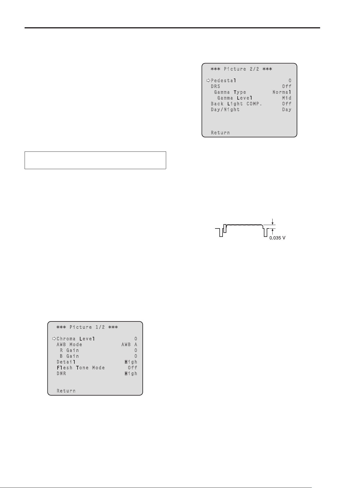
P i c t u r e 2 / 2
Pede s t a l 0
DRS Of f
Gam m a T y p e N o r ma l
Ga m m a L e v e l Mi d
Back L i g h t C O M P . Of f
Day/ N i g h t Da y
Retu r n
7 Press the [] button to start the “Pedestal”
value blinking.
8 Press the [] or [] button, change the
“Pedestal” value, and press the [] button to
enter the selection.
Adjust the black level to a value of approx. 0.035 V.
3 Select Manual1, Manual2 or Manual3 by
following the procedure in “How to select the
shooting mode” (page 11) under “Selecting the
shooting modes (scene files)”.
4 Press the [] or [] button to bring the cursor
to “Picture”.
5 Press the [] button.
The “Picture 1/2” sub-menu is displayed.
P i c t u r e 1 / 2
Chro m a L e v e l 0
AWB M o d e A W B A
R G a i n 0
B G a i n 0
Deta i l H ig h
Fles h T o n e M o d e Of f
DNR H ig h
Retu r n
9 Press the [MENU] button for 2 seconds.
The camera menu display is exited.
10
If necessary, press the [A/IRIS] button to adjust
the iris automatically.
27
Page 28

Black level (master pedestal) adjustment
(continued)
When performing the operations using the controller
When the AW‑RP655 is connected:
1 Press the [IRIS] button several times to turn off
its lamp.
Set the iris to the manual ([MANU]) mode.
2 Turn the [FOCUS/IRIS] dial to stop down the
lens iris.
3 Press the [R/B GAIN/PED] button several
times so that the “PEDESTAL TOTAL” item is
displayed on the LCD panel.
4 Turn the jog dial (main) and adjust the black
level to 0.035 V.
5 If necessary, adjust the iris automatically.
Press the [IRIS] button several times to turn on its
lamp.
When the AW‑RP555 is connected:
1 Press the [IRIS] button several times to turn off
its lamp.
Set the iris to the manual ([MANU]) mode.
2 Turn the [LEVEL] dial of [IRIS] to stop down the
lens iris.
3 Follow the operation steps in “Basic
operations” (page 38), and use the camera menu
to perform the adjustment.
When the AW‑RP50 is connected:
Refer to the Operating Instructions of the controller.
28
Page 29
Genlock adjustment (AW‑HE60S only)
pwGenlock adjustment
The genlock adjustment is performed to achieve phase
alignment by applying external synchronization (genlock)
when a multiple number of cameras will be used or when the
unit will be used in combination with other devices.
This unit supports the BBS signal as the genlock signal.
Ask your dealer to perform this adjustment.
(Use a dual-trace oscilloscope for the adjustment.)
(The genlock function is not available with the AW-HE60H.)
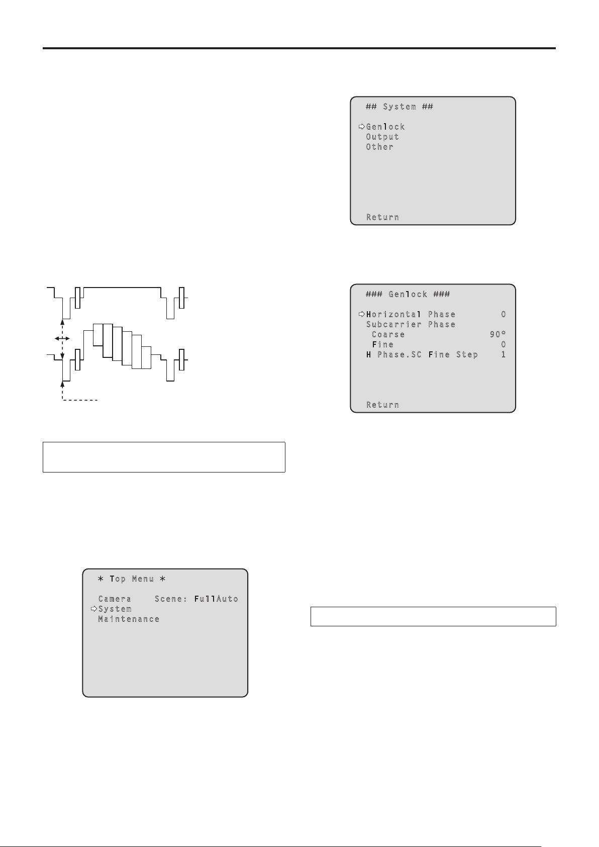
pqHorizontal phase adjustment
Observe the waveforms of the external sync signal input
(black burst signal) and video signal output on the dual-trace
oscilloscope, and use the wireless remote control or
controller to bring the horizontal phase into alignment.
External sync signal
input (black burst signal)
Video signal output
3 Press the [] button.
The “System” sub-menu is displayed.
S y s t e m
Genl o c k
Outp u t
Othe r
Retu r n
4 Press the [] or [] button to bring the cursor
to “Genlock”, and press the [] button.
The “Genlock” sub-menu is displayed.
G e n l o c k
Hori z o n t a l P h a s e 0
Subc a r r i e r P h a s e
Coa r s e 90 °
Fin e 0
H Ph a s e . S C F i n e S t ep 1
Bring the horizontal phase into alignment.
When performing the operations
using the wireless remote control
1 Follow the operation steps in “Basic
operations” (page 34) to display the Top Menu.
2 Press the [] or [] button to bring the cursor
to “System”.
Top M e n u
Camer a S c e n e : F ul l A ut o
Syste m
Maint e n a n c e
Retu r n
5 Press the [] or [] button to bring the cursor
to “Horizontal Phase”, and press the [] button.
The “Horizontal Phase” value starts blinking.
6 Press the [] or [] button to change the
“Horizontal Phase” value, adjust the value
so that the horizontal phase is brought into
alignment, and press the [] button.
7 Press the [MENU] button for 2 seconds.
The camera menu display is exited.
When performing the operations using the controller
These operations can be performed using the camera
menus by following the operation steps in “Basic operations”
(pages 32 to 39).
29
Page 30
Genlock adjustment (AW‑HE60S only)
(continued)
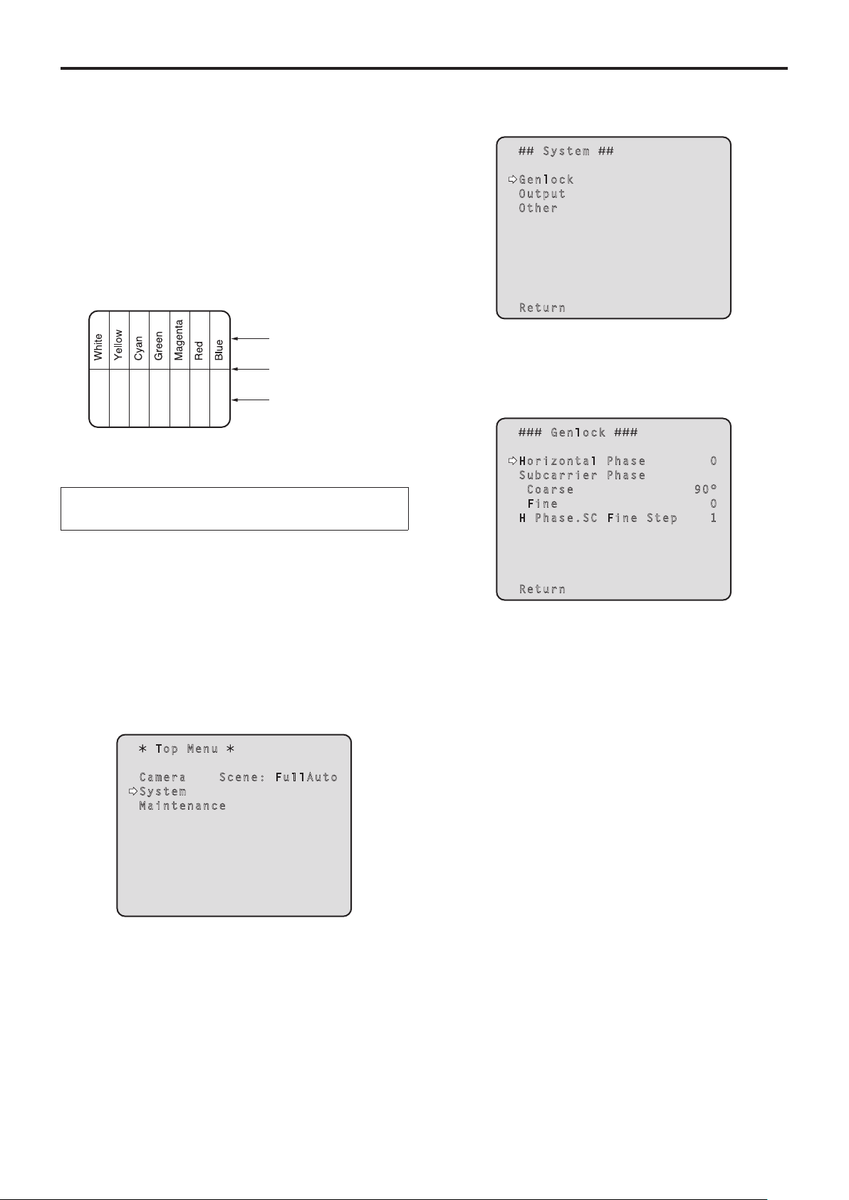
pqColor phase adjustment
The color phase adjustment must be performed if the
pictures are to be switched using a video switcher or other
device when the video output signals have been set as
composite signals.
It need not be performed when the video output signals have
been set as component signals.
The camera’s color phase is aligned with the program output
(split color bar output) signals of a color special effect device
or other color tones that will serve as the reference.
(The color phase can be adjusted more accurately if a
vectorscope is used for the adjustment.)
Color bar of camera
Split line
Color bar of special
effects generator
When performing the operations
using the wireless remote control
4 Press the [] button.
The “System” sub-menu is displayed.
S y s t e m
Genl o c k
Outp u t
Othe r
Retu r n
5 Press the [] or [] button to bring the cursor
to “Genlock”, and press the [] button.
The “Genlock” sub-menu is displayed.
G e n l o c k
Hori z o n t a l P h a s e 0
Subc a r r i e r P h a s e
Coa r s e 90 °
Fin e 0
H Ph a s e . S C F i n e S t ep 1
1 Press the [MODE] button.
The mode is switched to the color bar display.
2 Follow the operation steps in “Basic
operations” (page 34) to display the Top Menu.
3 Press the [] or [] button to bring the cursor
to “System”.
Top M e n u
Camer a S c e n e : F ul l A ut o
Syste m
Maint e n a n c e
Retu r n
6 Press the [] or [] button to bring the cursor
to “Coarse” or “Fine” of “Subcarrier Phase”,
and press the [] button.
The “Coarse” or “Fine” value starts blinking.
7 Press the [] or [] button to change the
“Coarse” or “Fine” value of “Subcarrier Phase”,
adjust the value so that the color phase is
brought into alignment, and press the []
button.
8 Press the [MENU] button for 2 seconds.
The menu display is exited.
9 Press the [MODE] button.
The mode is switched to the camera picture display.
30
Page 31

Genlock adjustment (AW‑HE60S only)
When performing the operations using the controller
These operations can be performed using the camera
menus by following the operation steps in “Basic operations”
(pages 32 to 39).
To switch between “BAR” (color bar display) and “CAM”
(camera pictures), press the [MODE] or [BAR/CAM] button.
(continued)
31
Page 32

Basic operations
Camera menus are displayed on the monitor when the unit’s
settings are to be selected.
The monitor is connected to the video signal output
connector.
The basic camera menu operations involve displaying
sub-menus from the Top Menu items, and selecting settings
on the sub-menus.
Some sub-menus have menu items for performing more
detailed settings.
The camera menu operations are conducted using the
wireless remote control.
If a controller is connected, they can also be conducted using
the controller.
p It may be necessary to upgrade the controller’s version in
order to support the AW-HE60.
For further details, consult with your dealer.
Described below are the basic operations for changing the
camera menu item settings using the wireless remote control
and controller (AW-RP655, AW-RP555 or AW-RP50).
Only the steps taken using the wireless remote
control will be described here for the operations
conducted to select and set the items.
For details of the operations conducted using the
controller, substitute “controller” for “wireless
remote control” when reading the basic operations.
Also, refer to the Operating Instructions of the
controller.
Table of operations
Camera menu
operation
Selecting the
unit to be
operated
Displaying the
Top Menu
Selecting the
items
Displaying the
sub‑menus
Wireless remote
control
Press the [CAM1],
[CAM2], [CAM3] or
[CAM4] button.
Press the [MENU]
button for 2 seconds.
Press the [] or []
([] or []) button.
Press the [] button.
Controller
AW‑RP655 AW‑RP555 AW‑RP50
Press one of the [1] to [5]
buttons of [CONTROL/
PREVIEW MONITOR OUT
SEL].
1. Press the [MENU] button.
The display on the
AW-RP655’s LCD panel
changes to the menu mode.
2. Turn the jog dial (main)
to display “CAMERA
SETTING” on the LCD
panel, and press the [OK]
button.
3. The scene selection menu
now appears on the LCD
panel so select the scene to
be set, and press the [OK]
button.
4. If the “OPEN CAMERA
MENU? OK Key”
message appears on the
LCD panel, press the [OK]
button again.
Turn the jog dial (main). Press the [YES] or [NO] button. Turn the F1 dial.
Press the jog dial (main). Press the [ITEM] button. Press the F1 dial.
Press one of the [1] to [5]
buttons of [CONTROL].
Press the [MENU] button for
2 seconds.
Press one of the [CAMERA
STATUS/SELECTION] buttons.
Press the [CAMERA OSD]
button for 2 seconds.
32
Page 33

Basic operations
(continued)
Camera menu
operation
Returning to the
previous menu
Changing the
settings
Canceling the
setting change
Exiting the
camera menu
operations
Wireless remote
control
With the cursor at
the [Return] position,
press the [] button.
With the cursor at the
item to be changed,
press the [] button to
start the item’s value
blinking.
Use the [], [], []
and [] buttons to
change the value, and
press the [] button to
enter the change.
While the setting
is blinking, press
the [MENU] button
quickly (for less than
2 seconds).
Press the [MENU]
button for 2 seconds.
AW‑RP655 AW‑RP555 AW‑RP50
With the cursor at the [Return]
position, press the jog dial
(main).
1. Press the jog dial (main) to
start the setting blinking.
2. Turn the jog dial (main) to
change the setting.
3. Press the jog dial (main) to
enter the setting (and stop
the blinking).
While the setting is blinking,
press the jog dial (R).
Press the [MENU] button or
[R/B GAIN/PED] button.
Controller
With the cursor at the [Return]
position, press the [ITEM]
button.
1. Press the [ITEM] button to
start the setting blinking.
2. Press the [YES] or [NO]
button to change the setting.
3. Press the [ITEM] button to
enter the setting (and stop
the blinking).
While the setting is blinking,
press the [MENU] button.
Press the [MENU] button for
2 seconds.
With the cursor at the [Return]
position, press the F1 dial.
1. Press the F1 dial to start the
setting blinking.
2. Turn the F1 dial to change
the setting.
3. Press the F1 dial to enter
the setting (and stop the
blinking).
—
Press the [CAMERA OSD]
button for 2 seconds.
Notes
p Perform the menu operations and exit from the menus using the controller which displayed the Top Menu.
If a menu operation has been performed or a menu has been exited using another controller, first display the Top Menu
and exit from it using one controller, and then display the Top Menu and exit from it using the other controller.
p The unit uses a different method to operate its menus from the one employed by the convertible cameras (except for the
AW-HE870) and HD integrated cameras which have already been launched onto the market.
For details, refer to the Operating Instructions of the camera concerned.
p The response speed of the camera differs slightly depending on the controller used.
33
Page 34

Basic operations
(continued)
pwWhen performing the
operations using the wireless
remote control
1 Press the [CAM1], [CAM2], [CAM3] or [CAM4]
button to select the unit which is to be
operated.
2 Press the [MENU] button for 2 seconds.
The Top Menu is displayed.
3 Press the [] or [] button to bring the cursor
to the item to be selected.
Each time the [] or [] button is pressed, the cursor
moves.
The cursor can be moved in the same way using the []
and [] buttons.
4 Press the [] button.
The sub-menu of the selected item is displayed.
(Some sub-menu items have a sub-menu of their own.)
8 Press the [] button.
The value of the item to be set is entered, and it stops
blinking.
9 After the setting has been completed, press the
[MENU] button for 2 seconds.
The camera menu display is exited.
5 Press the [] or [] button to bring the cursor
to the item to be set.
Each time the [] or [] button is pressed, the cursor
moves.
The cursor can be moved in the same way using the []
and [] buttons.
With the cursor at the “Return” position, press the []
button to return to the previous menu.
6 Press the [] button.
The value of the item to be set starts blinking.
7 Press the [] or [] button to change the
setting.
The setting can be changed in the same way using the
[] and [] buttons.
34
Page 35

Basic operations
(continued)
pwControl exercised from the Multi‑Function Controller AW‑RP655
Each time the [MODE] button is pressed, the
setting is switched between CAM and BAR.
The [MODE] button lights up at the BAR setting.
This is used to switch between AUTO and
MANU for the gain. The [GAIN] button
lights when the AUTO setting is selected.
For switching WHITE BAL A,
B or ATW.
For executing AWB.
*1, *2
The unit does not have
an ABC function.
This is used to acquire the
statuses of the camera and
synchronize the data. *3
Jog dial (L)
When the LCD is in the gain
adjustment mode
Adjust the R GAIN setting (–150 to
+150). *4, *7
Jog dial (main)
When the LCD is in the gain adjustment
mode ([GAIN] button: MANU)
Select the desired gain setting from GAIN
0 dB to 18 dB. *5
When the LCD is in the gain adjustment
mode ([GAIN] button: AUTO)
Select the desired gain setting from AGC MAX
GAIN 6 dB, 12 dB or 18 dB.
When the LCD is in the pedestal adjustment
mode
Adjust the PEDESTAL TOTAL setting (–150 to
+150). *6
When the camera menu mode is established
Perform the camera menu operations.
These are used for menu
operation.
Jog dial (R)
When the LCD is in the camera
menu mode
Press the jog dial (R) to cancel the
setting change.
When the LCD is in the gain
adjustment mode
Adjust the B GAIN setting (–150 to
+150). *4, *7
Each time the [EXT(AF)]
button is pressed,
the focus setting is
switched between auto
focus and manual focus.
When auto focus is
selected, the [EXT(AF)]
button lights.
When the focus setting
is switched between
auto focusing and
manual focusing by the
camera, the resulting
status (lamp on or off)
will not be reflected in
the button.
This is used to switch
between the Day mode
and Night mode.
For selecting the
cameras to be operated.
*1: The AWC switch indicator blinks while the white
balance is being adjusted.
When AWB is completed successfully, the lamp
goes off; when it is not completed successfully, it
lights up.
*2: The switch lights without AWB being executed when
the white balance mode of the main unit is ATW, or
when the Color Bar is being displayed.
*3: SCENE FILE, CAM/BAR, and GAINUP of each
SCENE, as well as the W/B MODE statuses are
synchronized.
*4: The R gain and B gain cannot be adjusted if ATW is
used as the White Balance Mode setting.
*5: With this unit, the gain setting is reflected in
increments of 3 dB in the control.
*6: With this unit, the setting is reflected in increments
of 15 dB in the control.
On the camera menu, the setting is adjusted in
range from –10 to +10.
*7: With this unit, the setting is reflected in increments
of 5 dB in the control.
On the camera menu, the setting is adjusted in
range from –30 to +30.
35
Page 36

Basic operations
(continued)
pqProcedure for camera menu operation
(AW‑RP655)
1 Press one of the [1] to [5] buttons of
[CONTROL/PREVIEW MONITOR OUT SEL] to
select the unit which is to be operated.
2 Press the [MENU] button to set the LCD panel
display to the menu mode.
3 Turn the jog dial (main) until CAMERA SETTING
appears, and press the [OK] button.
CAMERA SETTING
OK Key
4 When the scene selection menu has appeared
on the LCD panel, select the scene to be set,
and press the [OK] button.
SCENE HALOGEN
OK Key
6 Turn the jog dial (main) to select camera menu
items of the AW‑HE60 and change the data.
Turn the jog dial (main) when the cursor is to be moved
up or down or the settings are to be changed.
Press it when moving to the menu at the next lower
hierarchical level or changing a setting at the very bottom
hierarchical level.
7 Press the [MENU] button to exit the camera
menu.
Notes
p Genlock is set using the camera menu for the
AW-HE60.
p It may be necessary to upgrade the software version
in order to operate an AW-HE60 from an AW-RP655.
Ask your dealer for details.
The scene names displayed on the LCD panel correlate
with the scene files of the AW-HE60 as shown below.
AW‑RP655 display AW‑HE60 scene file
HALOGEN Manual1
FLUORESCENT Manual2
OUTDOOR Manual3
USER FullAuto
5 When the following message appears on the
LCD panel, press the [OK] button again.
OPEN CAMERA MENU ?
OK Key
The camera menu of the AW-HE60 is displayed on the
monitor.
36
Page 37

Basic operations
(continued)
pwControl exercised from the Multi Hybrid Control Panel AW‑RP555
Each time the [GAIN] button is
pressed, the setting is switched in
the sequence of GAIN AUTO
0dB L (9dB) H (18dB), and the
mode is displayed by the LEDs as
shown below.
[ON: LED lights; OFF: LED off]
GAIN
AUTO ON OFF OFF
button
0dB OFF OFF OFF
LOW OFF ON OFF
HIGH OFF OFF ON
Others OFF ON ON
MANU L
LED
MANU H
LED
For executing AWB. *1, *2
Each time the [MODE] button is
pressed, the setting is switched
between CAM and BAR.
The [MODE] button lights up at the
BAR setting.
For selecting the cameras to be
operated.
For switching the contrast
mode. *3
Shutter mode selection
Each time this button is pressed, one of the shutter
modes set by the controller or “shutter OFF” is
selected.
The [SHUTTER] button lights up in all modes except
shutter OFF.
The shutter mode settings established by the
[PRESET] buttons are as follows.
1
2
PRESET
No.
PRESET1
MODE
1/4000 PRESET6
1/10000 PRESET7
SYNCHRO-
SCAN
MODE
1/100**
1/120**
1/250 PRESET2
1/500 PRESET3
1/1000 PRESET4 ELC PRESET9
1/2000 PRESET5 OFF PRESET10
**1: “1/100” when 59.94 Hz is selected as the frequency setting
of the AW-HE60.
**2: “1/120” when 50 Hz is selected as the frequency setting of
the AW-HE60.
PRESET
No.
PRESET8
For switching WHITE BAL A,
B or ATW. *4
The unit does not have
an ABC function.
For switching the SCENE file
(FullAuto, Manual1 to 3).
For operating the camera menus.
MENU: This operates in the same
way as MENU on the
camera.
ITEM: This operates in the same
way as ENTER on the
camera.
YES: This operates in the same
way as UP on the camera.
NO: This operates in the same
way as DOWN on the
camera.
This is used to switch between the
Day mode and Night mode.
Each time the [(AF)EXT] button
is pressed, the focus setting is
switched between auto focus and
manual focus.
When auto focus is selected, the
[(AF)EXT] button lights.
When the focus setting is
switched between auto focusing
and manual focusing by the
camera, the resulting status (lamp
on or off) will not be reflected in
the button.
*1: The lamp of the AWC switch flashes while automatic
white balance is being executed.
When AWB is completed successfully, the lamp
goes off; when it is not completed successfully, it
lights up.
*2: The switch lights without AWB being executed when
the white balance mode of the main unit is ATW, or
when the Color Bar is being displayed.
*3: The contrast level can be adjusted in the AUTO
mode.
*4: There is a delay in the switching of the display when
the settings are changed on the camera.
37
Page 38

Basic operations
(continued)
pqProcedure for camera menu operation
(AW‑RP555)
1 Press one of the [1] to [5] buttons of
[CONTROL] to select the unit which is to be
operated.
2 Press the [MENU] button of the AW‑RP555 for
2 seconds.
The camera menu of the AW-HE60 is displayed on the
monitor.
3 Perform one of the following steps to select the
menu item.
If the [YES] button is pressed, the selection item moves
up; if the [NO] button is pressed, it moves down.
4 Press the [ITEM] button.
The value of the item to be set starts blinking.
Note
p It may be necessary to upgrade the software version
in order to operate an AW-HE60 from an AW-RP555.
Ask your dealer for details.
5 Press the [YES] or [NO] button to change the
setting.
6 After deciding on the setting, press the [ITEM]
button.
The value of the item to be set is entered, and it stops
blinking.
7 Press the [MENU] button for 2 seconds to exit
the camera menu.
38
Page 39

Basic operations
(continued)
pwControl exercised from the Remote Camera Controller AW‑RP50
F1
POWER ALARM F1 CAMERA
1 2 3
R/B GAIN R/B PED
6 7 8 9 10
DETAIL
SCENE/MODE
PRESET MEMORY / MENU
1 2 3 4 5
CAMERA STATUS / SELECTION
AUTO
AWB/ABB4SHUTTER
TELE
GAIN/PED
PAGEMENU F2 EXIT
DELETESTORE
ZOOM
WIDE
F2
5
SYSTEMSETUPCAMERA
PTZ/FOCUS SPEEDFOCUS/PUSH OAF
HILOW
OSD
USER2USER1
PT ACTIVEAUTOIRIS
For operating the camera menus.
CAMERA OSD:
When this is pressed for
2 seconds, the selected camera
menu is displayed, overlapping
the camera output image.
When it is pressed for
2 seconds while a camera
menu is displayed, the menu is
cleared.
F1: Turn F1 to move the cursor up
or down on the camera menu or
change the setting.
Press it when moving to
the menu at the next lower
hierarchical level or changing
a setting at the very bottom
hierarchical level.
For selecting the cameras to be operated.
pqProcedure for camera menu operation (AW‑RP50)
1 Press one of the [CAMERA STATUS/
SELECTION] buttons to select the unit which
is to be operated.
2 Press the [CAMERA OSD] button of the
AW‑RP50 for 2 seconds.
The camera menu of the AW-HE60 is displayed on the
monitor.
3 Turn the F1 dial to select the AW‑HE60 camera
menu item or change the data.
Turn the F1 dial to move the cursor up or down or
change the setting.
Press it to move to the menu at the next lower
hierarchical level or change a blinking setting at the very
bottom hierarchical level.
4 Press the [CAMERA OSD] button for 2 seconds
to exit the camera menu.
39
Page 40

Camera menu items
pwSetting the camera menu items
When the unit’s settings are to be selected, the camera
menus are displayed on the monitor.
The monitor is connected to the video signal output
connector.
The basic camera menu operations involve displaying
sub-menus from the Top Menu items, and selecting settings
on the sub-menus.
Some sub-menus have menu items for performing more
detailed settings.
For details on the basic operations to display the camera
menus and change the items using the wireless remote
control or controller (AW-RP655, AW-RP555 or AW-RP50),
refer to pages 32 to 39.
The “
” and “ ” marks in the menu titles indicate the
hierarchical level of the menu currently displayed.
For instance, “
hierarchical level whereas “
“
level is now displayed.
Menu items accompanied by a “
which is stored on a scene by scene basis; menu items
accompanied by a “
together for one camera regardless of the scenes.
” indicate that the second hierarchical
” mark indicate data which is stored
” indicates the first
” and
” mark indicate data
pwTop Menu screen
Top M e n u
Camer a S c e n e : F ul l A ut o
Syste m
Maint e n a n c e
Camera
Select this to open the camera menu relating to the
camera images.
System
Select this to display the System menu used to adjust the
genlock (external synchronization) phase or establish the
camera output image settings.
Maintenance
Display the Maintenance menu which concerns checking
the unit’s firmware versions, checking the IP address and
initialize the settings.
Note
p The Top Menu does not have a “Return” setting.
To close the menu screen, use the controller to
perform the operation to close the menu screen.
For details, refer to pages 32 to 39.
40
Page 41

Camera menu items
(continued)
pwCamera screen
(when FullAuto is selected)
This menu is used for the camera image settings.
C a m e r a
Scen e F ul l A ut o
Con t r a s t L e v e l 0
Day / N i g h t Da y
Retu r n
Scene
[FullAuto, Manual1, Manual2, Manual3]
Selected here is the shooting mode that matches the
shooting situation.
Select the mode which best suits the prevailing shooting
conditions and the user’s preferences.
FullAuto: In this mode, the optimum settings and
adjustments for the shooting conditions at
hand are automatically established.
When “FullAuto” has been selected, the
detailed setting and adjustment menus are
not displayed.
Manual1 to 3: In these modes, the detailed settings and
adjustments are established manually to
match the prevailing shooting conditions
and the user’s preferences.
When the Manual1, Manual2 or Manual3
mode has been selected, the detailed
setting and adjustment menu for the mode
concerned is displayed.
Contrast Level [–5 to +5]
Use the contrast level to adjust the image brightness.
pwCamera screen
(when Manual1 to 3 is selected)
C a m e r a
S c e n e Ma n u al 1
C o n t r a s t
P i c t u r e
C o l o r M a t r i x
R e t u r n
Scene
[FullAuto, Manual1, Manual2, Manual3]
Refer to section on Scene in the column on the left.
Contrast
Select this to display the Contrast screen to adjust the
brightness.
Picture
This menu item displays the Picture screen on which to
adjust the picture quality.
Two screens (Picture 1/2 and Picture 2/2) are provided for
the picture quality adjustment menu.
Color Matrix
This menu item is used to adjust the 16-axis color matrix.
Return
Use this to return to the previous menu.
Day/Night [Day, Night]
This is used to select normal shooting or low light shooting
(by exposing the subjects to infrared rays).
Day: Normal shooting
Night: Low light shooting
In Night mode, Black-and-white images are
output.
The lens iris is forcibly set to open.
Return
Use this to return to the previous menu.
41
Page 42

Camera menu items
(continued)
pwContrast screen
C o n t r a s t
Contr a s t M o d e A ut o
Cont r a s t L e v e l 0
Shut t e r M o d e - -- Ste p / S y n c h r o - -- Fra m e M i x - -- Aut o F . M i x M a x G a in 0d B
Gain A ut o
AGC M a x G a i n 1 8d B
Retur n
Contrast Mode [Auto, Manual]
This item is used to select whether the image brightness
(contrast) is to be controlled automatically or manually.
Auto: The iris, shutter speed and frame addition
are controlled and the camera brightness is
adjusted automatically.
Manual: Operations are performed using the manually
set values.
Contrast Level [–5 to +5]
Set here is the contrast level when the image brightness
is adjusted.
This item can be set when “Auto” has been selected as
the “Contrast Mode” setting.
Shutter Mode [Off, Step, Synchro]
Select for camera shutter speed.
This item can be set when “Manual” has been selected as
the “Contrast Mode” setting.
Off: The shutter is set to OFF (so that it cannot be
tripped).
Step: The step shutter is set (the steps can be
changed).
Synchro: The synchro shutter is set (the setting can be
changed continuously).
Frame Mix [Auto, Off, 6dB, 12dB, 18dB]
Select for frame addition (gain-up using sensor storage)
amount.
This item can be set when “Off” is selected as the “Shutter
Mode” item setting.
When frame addition is performed, it will appear as if the
images are missing some frames.
AutoF. Mix Max Gain
[0dB, 6dB, 12dB, 18dB]
When “Auto” for the “Contrast Mode” or “Auto” for the
“Frame Mix” is selected, the maximum frame addition
amount can be set.
If frame addition is performed at the Auto setting, it will
appear as if the images are missing some frames.
Gain [Auto, 0dB, 3dB, 6dB, 9dB, 12dB, 15dB, 18dB]
The image gain is adjusted here.
In locations which are too dark, adjust the gain upward;
conversely, in locations which are too bright, adjust it
downward.
When “Auto” is set, the light quantity is adjusted
automatically.
The noise increases when the gain is increased.
AGC Max Gain [6dB, 12dB, 18dB]
When “Auto” is selected as the “Gain” setting, the
maximum gain-up amount can be set.
Return
Use this to return to the previous menu.
Step/Synchro
This is used to adjust the shutter speed in the mode which
was selected as the “Shutter Mode” setting.
When a higher shutter speed is selected, fast-moving
subjects do not become blurred easily but the images will
be darker.
The shutter speeds that can be set are listed below.
[When 59.94 Hz has been set as the unit’s frequency]
When “Step” is selected as
the “Shutter Mode”
1/100, 1/250, 1/500, 1/1000,
1/2000, 1/4000, 1/10000
[When 50 Hz has been set as the unit’s frequency]
When “Step” is selected as
the “Shutter Mode”
1/120, 1/250, 1/500, 1/1000,
1/2000, 1/4000, 1/10000
When “Synchro” is selected
as the “Shutter Mode”
60.24 Hz to max. 646.21 Hz
(255 steps)
When “Synchro” is selected
as the “Shutter Mode”
50.20 Hz to max. 538.51 Hz
(255 steps)
42
Page 43

Camera menu items
(continued)
pwPicture 1/2 screen
P i c t u r e 1 / 2
Chro m a L e v e l 0
AWB M o d e A W B A
R G a i n 0
B G a i n 0
Deta i l H ig h
Fles h T o n e M o d e Of f
DNR H ig h
Retu r n
Chroma Level [–3 to +3]
Set here is the color intensity (chroma level) of the
images.
AWB Mode [ATW, AWB A, AWB B]
The white balance mode is selected here.
Select the mode when the coloring is not natural because
of the nature of the light source or other factors.
If the white color serving as the reference can be
recognized, subjects can be shot with natural coloring.
ATW: In this mode, the white balance is compensated
for automatically, even if changes occur in the
light source or color temperature, by a process of
continuous and automatic adjustment.
AWB A, AWB B:
When AWB A or AWB B is selected and the
white balance is executed, the adjustment results
obtained are stored in the memory selected.
When AWB A or AWB B is then selected, the white
balance stored in the selected memory can be
recalled.
R Gain, B Gain [–30 to +30]
When “AWB A” or “AWB B” is selected as the AWB Mode
setting, the white balance can be finely adjusted after
automatic white balance (AWB) has been performed.
Notes
p When automatic white balance (AWB) is executed,
the R Gain and B Gain values are returned to “0”.
p When “AWB A” or “AWB B” is selected as the AWB
Mode setting, the R Gain and B Gain adjustment
values can be stored in the two memories, A and B.
p When new values are set, the previous values are
erased.
Use each of the memories for a different purpose in
accordance with the shooting conditions.
p In terms of registering values in the preset
memories, the R Gain and B Gain settings (–30 to
+30) are not stored, but the white balance (color)
status after adjustments have been made using the
R Gain and B Gain items can be stored.
p If settings in the preset memories are recalled
when “Mode A” has been selected as the Preset
Scope setting, the R Gain and B Gain settings are
returned to “0”.
p When “ATW” has been selected as the AWB Mode
setting, the R Gain and B Gain cannot be adjusted.
Detail [Off, Low, High]
The image detail (image sharpness) is adjusted here.
When “Low” or “High” is selected, the detail is enhanced.
Flesh Tone Mode [Off, Low, High]
Set here is the flesh tone mode for displaying the subjects’
skin so that it appears more smoothly and eye-pleasingly.
When “Low” or “High” is selected, the effect is enhanced.
Note
p When preset settings have been called from the
AW-RP655, the AWB mode which was set when the
preset data was registered by the AW-RP655 will
be called.
DNR [Off, Low, High]
Set here is the level of the digital noise reduction effect so
that light, noise-free and clear images will be output even
at night and in other low-brightness environments.
When “Low” or “High” is selected, noise can be eliminated.
However, there is an increased possibility that afterimages
may occur.
Return
Use this to return to the previous menu.
43
Page 44

Camera menu items
(continued)
pwPicture 2/2 screen
P i c t u r e 2 / 2
Pede s t a l 0
DRS Of f
Gam m a T y p e N o r ma l
Ga m m a L e v e l Mi d
Back L i g h t C O M P . Of f
Day/ N i g h t Da y
Retu r n
Pedestal [–10 to +10]
This item is used to adjust the black level (adjust the
pedestal) so that the dark parts of the images are easier
to see.
These parts become darker when a negative setting is
selected and, conversely, lighter when a positive setting is
selected.
DRS [Off, Low, High]
Set here is the DRS function which provides just the right
amount of compensation when images with significant
light/dark differences are displayed.
When “Low” or “High” is selected, the effect is enhanced
even more.
This may make noise more perceptible with some scenes.
Day/Night [Day, Night]
This is used to select normal shooting or low light shooting
(by exposing the subjects to infrared rays).
Day: Normal shooting
Night: Low light shooting
In Night mode, Black-and-white images are
output.
The lens iris is forcibly set to open.
Return
Use this to return to the previous menu.
Gamma Type [Off, Normal, Cinema]
Selected here is the type of gamma curve.
The selected setting takes effect when “Off” is selected as
the “DRS” item setting.
Normally, the “Normal” setting is used.
When “Cinema” is selected, images giving off an
atmosphere like movies can be shot.
Gamma Level [Low, Mid, High]
This item is used to adjust the gamma compensation level.
The item’s setting takes effect when “Off” has been
selected as the “DRS” setting and “Normal” as the
“Gamma Type” setting.
When “Low” is set, the images appear sedate and
composed. The resulting gamma curve has a gentle
gradient in the low-brightness areas, and the contrast is
sharper.
Conversely, when “High” is set, the tonal range in the dark
area is expanded so that the images take on a lighter
tone. The resulting gamma curve has a sharp gradient in
the low-brightness areas, and the contrast is softer.
Back Light COMP. [Off, On]
“On” or “Off” is set here for the backlight compensation
function.
Under backlight conditions, the function prevents
darkening as a result of light striking the backs of subjects,
and makes it possible to shoot images in shade or shadow
more brightly.
The function takes effect when “Auto” has been selected
as the Contrast Mode, Gain or Frame Mix item setting.
44
Page 45

Camera menu items
(continued)
pw16‑axis color matrix
(These operations can be performed only when
Manual1 to 3 has been selected as the Scene setting.)
<Color Matrix 1/3 screen>
C o l o r M a t r i x 1 /3
Mat r i x S e l e c t N o r ma l
[ S a t u r a t i o n] [P h a se ]
Ax i s 0 1 - - - - - - - Ax i s 0 2 - - - - - - - Ax i s 0 3 - - - - - - - Ax i s 0 4 - - - - - - - Ax i s 0 5 - - - - - - - Ax i s 0 6 - - - - - - --
Ret u r n
<Color Matrix 2/3 screen>
C o l o r M a t r i x 2 /3
Mat r i x S e l e c t N o r ma l
[ S a t u r a t i o n] [P h a se ]
Ax i s 0 7 - - - - - - - Ax i s 0 8 - - - - - - - Ax i s 0 9 - - - - - - - Ax i s 1 0 - - - - - - - Ax i s 1 1 - - - - - - - Ax i s 1 2 - - - - - - --
Matrix Select [Normal, EBU, NTSC, User]
The preset color matrix data is loaded, and the saturation
and phase are compensated accordingly.
When “User” is selected, the saturation and phase can be
finely adjusted using the 16-axis color matrix (Axis 01 to
Axis 16).
ColorMatrix, Color Position
Axis 5
90°
Cy@284°
Axis 4
67.5°112.5°
MG@61°
Axis 14
Axis 3
45°
B@348°
315°
Axis 15
Axis 2
22.5°
0°
337.5°
Axis 16
Axis 9
Axis 8
157.5°
180°
202.5°
Axis 10
Axis 7
135°
Ye@168°
225°
Axis 11
Axis 6
R@104°
G@241°
247.5° 292.5°
270°
Axis 12
Axis 13
Axis 1
Ret u r n
<Color Matrix 3/3 screen>
C o l o r M a t r i x 3 /3
Mat r i x S e l e c t N o r ma l
[ S a t u r a t i o n] [P h a se ]
Ax i s 1 3 - - - - - - - Ax i s 1 4 - - - - - - - Ax i s 1 5 - - - - - - - Ax i s 1 6 - - - - - - --
Ret u r n
Axis 01 to Axis 16: Saturation [–127 to +127]
The saturation of Axis 01 to Axis 16 can be finely
adjusted.
Axis 01 to Axis 16: Phase [–127 to +127]
The phase of Axis 01 to Axis 16 can be finely adjusted.
Return
Use this to return to the previous menu.
45
Page 46

Camera menu items
(continued)
pwSystem screen
This menu has items that relate to the genlock phase
adjustment and camera’s output image settings.
S y s t e m
Genl o c k
Outp u t
Othe r
Retu r n
Genlock (AW‑HE60S only)
This displays the Genlock screen on which to perform the
phase adjustments.
With the AW-HE60H, this item cannot be selected.
Output
This displays the Output screen on which to select the
camera’s output image settings.
pwGenlock screen
(AW‑HE60S only)
G e n l o c k
Hori z o n t a l P h a s e 0
Subc a r r i e r P h a s e
Coa r s e 90 °
Fin e 0
H Ph a s e . S C F i n e S t ep 1
Retu r n
Horizontal Phase [–206 to +49]
This is used to adjust the horizontal phase during genlock.
Subcarrier Phase Coarse [0° to 315°]
This is used to adjust coarsely the color phase during
genlock.
This setting is valid for the VBS signal output.
Other
This displays the Other screen on which to select the
settings for the installation status of the camera’s pan-tilt
head unit and operating speed as well as the settings
relating to the other functions.
Return
Use this to return to the previous menu.
Subcarrier Phase Fine [–127 to +127]
This is used to adjust finely the color phase during
genlock.
This setting is valid for the VBS signal output.
H Phase. SC Fine Step [1 to 10]
This is used to select the amount by which the horizontal
phase (Horizontal Phase) is to be adjusted and by which
the color phase (Subcarrier Phase Fine) is to be adjusted
finely.
Return
Use this to return to the previous menu.
46
Page 47

Camera menu items
(continued)
pwOutput screen
O u t p u t
Form a t 1 0 80 i
Down C O N V . M o d e L e tt e r Bo x
HDMI C o l o r Y Cb C r 42 2
Retu r n
Format
[1080/59.94p, 1080/59.94i, 720/59.94p, 480/59.94p,
480/59.94i, 1080/29.97PsF, 1080/50p, 1080/50i,
720/50p, 576/50p, 576/50i, 1080/25PsF]
The video format is changed on this screen.
The formats of the images which can be output differ
between the AW-HE60H and AW-HE60S.
For details on how to change the format, refer to
“Changing the format” (page 48).
Down CONV. Mode
[Squeeze, SideCut, LetterBox]
The down-conversion mode is selected here.
When the 4:3 aspect ratio has been set
for the monitor screen, the images are
squeezed horizontally and extended
Squeeze
vertically changing the view of the angle.
HDMI Color (AW‑HE60H only)
[RGB‑NOR, RGB‑ENH, YCbCr422, YCbCr444]
Set here is the HDMI color output.
When an HDMI monitor is used, use “YCbCr422” under
normal circumstances.
In cases where, for instance, HDMI (RGB) signals are
converted and output to a DVI monitor, the settings
required will differ depending on the color gradation
supported by the monitor.
RGB-NOR The RGB output signals are output in the
16 to 235 range.
RGB-ENH The RGB output signals are output in the
0 to 255 range.
If the black parts of the images appear overexposed
when “RGB-NOR” has been selected, use the
“RGB-ENH” setting instead.
Conversely, if the images are displayed with a loss of
dark detail when “RGB-ENH” has been selected, use
the “RGB-NOR” setting instead.
Note
p If an HDMI Color setting which is not supported by
the monitor has been specified, the HDMI Color
setting may be changed automatically.
(The menu display will remain unchanged.)
With the AW-HE60S, this item cannot be selected.
Return
Use this to return to the previous menu.
With the vertical height serving as the
reference, the parts which extend beyond
this at the two sides are cropped changing
SideCut
LetterBox
p When output is selected for the color bar, the mode is fixed
to Squeeze.
If “SideCut” or “LetterBox” has been selected, the images
will not appear for a few seconds when the color bar
display is set to ON or OFF.
the view of the angle.
With the horizontal width serving as the
reference, black bands are added at the
top and bottom changing the view of the
angle.
47
Page 48

Camera menu items
(continued)
pqChanging the format
When the format is changed on the Output screen from its
current setting, the Format change check screen appears.
Format change check screen
F o r m a t
Do y o u w a n t t o
set F o r m a t ( 1 0 8 0 /5 9 .9 4 i )?
CANC E L
O.K.
The format to be set is displayed within the
parentheses on the screen.
Field frequency 59.94 Hz 50 Hz
When using the
AW‑HE60H
When using the
AW‑HE60S
1080/59.94p,
1080/59.94i,
720/59.94p,
480/59.94p,
480/59.94i,
1080/29.97PsF
1080/59.94i,
720/59.94p,
480/59.94i,
1080/29.97PsF
1080/50p,
1080/50i,
720/50p,
576/50p,
576/50i,
1080/25PsF
1080/50i,
720/50p,
576/50i,
1080/25PsF
Attention screen
A t t e n t i o n
Form a t ( 1 0 8 0 / 5 9 .9 4 i )
If y o u s e l e c t O .K .
The c a m e r a w i l l r e bo o t .
CANC E L
O.K.
The Attention screen is displayed in the following
cases:
- In the IP mode
- When a change is made from the
480/59.94i(59.94 Hz) or 576/50i(50 Hz) format to any
other format
- When a change is made from a format other than
480/59.94i (59.94 Hz) or 576/50i (50 Hz) format to
the 480/59.94i (59.94 Hz) or 576/50i (50 Hz) format
When the cursor is moved to [O.K.] on the Attention
screen and clicked, the unit is automatically rebooted,
and the format is changed.
When the cursor is moved to “CANCEL” on the
Attention screen and the setting is entered, the Format
unchanged screen appears for 5 seconds, the format
is left unchanged, and the display returns to the Output
screen.
When the cursor is moved to “O.K.” on the format
change check screen and the setting is entered, the
Format Set screen appears for a few seconds, and the
format is changed.
After the format has been changed, the display returns
to the Output screen.
With some types of monitors, the Format Set screen
may not be displayed.
Format Set screen
F o r m a t ( 1 0 8 0 / 5 9 . 94 i )
S e t
The format to be set is displayed within the
parentheses on the screen.
When the cursor is moved to “CANCEL” on the format
change check screen and the setting is entered, the
Format unchanged screen appears for 5 seconds, the
format is left unchanged, and the display returns to the
Output screen.
Format unchanged screen
For m a t
unc h a n g e d
48
Page 49

Camera menu items
(continued)
pwOther 1/2 screen
O t h e r 1 / 2
Insta l l P o s i t i o n De s k to p
Prese t S p e e d 1 0
Prese t S c o p e M o d e A
Digit a l Z o o m Di s a bl e
Speed W i t h Z o o m P O S. O n
Focus M o d e A ut o
Focu s A D J W i t h P T Z. - -- -
Retur n
Install Position [Desktop, Hanging]
“Desktop” or “Hanging” is selected here as the method
used to install the unit.
Desktop: Stand-alone installation
Hanging: Suspended installation
When “Hanging” has been selected, the top, bottom,
left and right of the images will be reversed, and
up/down/left/right control for panning and tilting will also
be reversed.
Digital Zoom [Disable, Enable]
“Enable” or “Disable” is set here for the digital zoom
function.
If zooming is performed toward the Tele end beyond the
maximum position when “Enable” has been selected, the
digital zoom can be operated continuously. Zooming will
stop temporarily at the position where the optical zoom
and digital zoom are switched so after it has stopped at
this position, proceed with zooming again.
When the setting is changed to “Disable” while already in
the digital zoom region, the zoom will automatically move
to the maximum position of the optical zoom.
Note
p The digital zoom is set to off when color bars are
displayed during digital zooming.
Speed With Zoom POS. [Off, On]
“Off” or “On” is set here for the function used to adjust the
camera direction’s adjustment speed in conjunction with
the zoom magnification.
When “On” is set, the panning and tilting operations will
become slower in the zoom status.
This function has no effect during preset operations.
Preset Speed [1 to 30]
There are 30 preset pan-tilt operation speeds when
regenerating the camera direction and other information
which are registered in the preset memory.
Notes
p If a high value is selected for the Preset Speed
setting, the image on the screen may shake when
operation stops.
p When connecting the unit to the AW-RP655 for use,
the “DIAGONAL SPEED (P/T SETTING)” setting of
the AW-RP655 takes effect.
To change the Preset Speed, change the
AW-RP655 setting.
Preset Scope [Mode A, Mode B, Mode C]
Selected here are the setting items to be recalled when
the contents of the preset memory are regenerated.
Mode A: Pan, Tilt, Zoom (including digital zoom), Focus,
Iris, Gain, White-BAL
Mode B: Pan, Tilt, Zoom (including digital zoom), Focus,
Iris
Mode C: Pan, Tilt, Zoom (including digital zoom), Focus
Focus Mode [Auto, Manual]
“Auto” or “Manual” is set here for the focusing function.
Auto: The subjects are always brought into focus
automatically.
Manual: The focus is operated manually.
Focus ADJ With PTZ. [Off, On]
“Off” or “On” is set here for the function which
compensates for out-of-focusing when it occurs during
panning, tilting or zooming operations at the manual focus
setting.
When “Off” is set, adjust the focus as required after
zooming or set the focus to the auto mode.
This item can be selected only when “Manual” has been
selected as the “Focus Mode” setting.
Return
Use this to return to the previous menu.
49
Page 50

Camera menu items
(continued)
pwOther 2/2 screen
O t h e r 2 / 2
Tal l y E n a b l e E n a bl e
OSD M i x
SD I / C O M P O f f B y Br o w se r
Br o w s e r / V i d e o O n
OSD O f f W i t h T a ll y Of f
OSD S t a t u s Of f
Wir e l e s s C o n t r o l E n a bl e
Ret u r n
Tally Enable [Disable, Enable]
“Enable” or “Disable” is set here for the function which
turns on or turns off the tally lamp using the tally control
signal.
OSD Mix
Whether the camera menus, statuses and other displays
are to be turned Off or On can be selected here for each
output picture.
SDI(HDMI)/COMP [Off, On, Off ByBrowser]
Browser/Video [Off, On]
Off: The camera menus and statuses are not displayed
on the output pictures targeted by the setting items
listed above.
On: The camera menus and statuses are displayed for
the output pictures covered by the setting items listed
above.
Off ByBrowser:
If a menu has been opened from the browser screen,
the camera menus and statuses are not displayed
on the output images for which this setting is
established.
Wireless Control [Disable, Enable]
“Enable” or “Disable” is set here for operations conducted
from the wireless remote control.
The operations are enabled when the unit’s power is
turned on from an external device other than a wireless
remote control, and they are disabled when the power is
turned on from a wireless remote control.
Notes
p At the point when this item’s setting is changed, the
new setting is not reflected in operation.
It is reflected when the unit is set to the standby
mode and its power is turned on.
p Follow one of the procedures below if the item’s
setting is changed by mistake and the unit can no
longer be operated from a wireless remote control.
When menu operations can be performed using
another control device:
First change the item using a control device
capable of performing menu operations, and
then turn off the unit’s power and turn it back
on.
When menu operations cannot be performed
using other control devices:
1. Turn off the power of the units and devices
that are connected.
2. Disconnect the unit’s power cable, and plug it
back in.
3. Perform the operation for turning on the unit’s
power from the wireless remote control.
4. After changing this item, turn off the unit’s
power and turn it back on.
Return
Use this to return to the previous menu.
Note
p Even if the display has been set to the off position
the camera menus will still be displayed for one
minute whenever the power of the unit is turned on.
OSD Off With Tally [Off, On]
This is used to enable or disable the function for clearing
the OSD menu displays when the tally signal is received
by a command or contact.
When the tally signal is released, the original OSD menu
displays are restored.
OSD Status [Off, On]
“Off” or “On” is set here for the status display which
appears during AWB operations.
50
Page 51

Camera menu items
(continued)
pwMaintenance screen
M a i n t e n a n c e
F i r m w a r e V e r s i o n
I P N e t w o r k
I n i t i a l i z e
R e t u r n
Firmware Version
This is selected to display the Firmware Version screen on
which to check the version of the firmware used.
IP Network
This is selected to display the IP Network screen on which
the user can check the IP Address, Subnet Mask and
Default Gateway settings which have been established in
the unit.
pwFirmware Version screen
F i r m w a r e V e rs i on
CPU S o f t w a r e
Cam e r a M a i n V 0 1 .0 0
Pan / T i l t V 0 1 .0 0
Net w o r k V 0 1 .0 0
PLD
Cam e r a V 0 1 .0 0
Out p u t V 0 1 .0 0
EEPR O M V 0 1 .0 0
Retu r n
CPU Software Camera Main
This is selected to display the software version of the
camera unit.
CPU Software Pan/Tilt
This is selected to display the software version of the pantilt unit.
CPU Software Network
This is selected to display the software version of the
network unit.
Initialize
This is selected to display the Initialize screen on which
the user can initialize the camera settings.
For details on operation, refer to “Concerning initialization”
on page 52.
Return
Use this to return to the previous menu.
PLD Camera
This is selected to display the PLD version of the camera
unit.
PLD Output
This is selected to display the PLD version of the output
unit.
EEPROM
This is selected to display the EEPROM version.
Return
Use this to return to the previous menu.
51
Page 52

Camera menu items
(continued)
pwIP Network screen
I P N e t w o r k
IP A d d r e s s
1 9 2 . 1 68 . 0 . 1 0
Subn e t M a s k
2 5 5 . 2 55 . 25 5 . 0
Defa u l t G a t e w a y
1 9 2 . 1 68 . 0 . 1
Retu r n
IP Address
This is selected to display the IP address which has been
set for the unit.
Subnet Mask
This is selected to display the subnet mask which has
been set for the unit.
Default Gateway
This is selected to display the default gateway which has
been set for the unit.
pqConcerning initialization
When “Initialize” is selected on the Maintenance screen, the
Initialize screen appears.
Initialize screen
I n i t i a l i z e
Do y o u w a n t t o in i ti a l iz e
Menu s e t t i n g s ?
CANC E L
O.K.
Retu r n
When the cursor is moved to “O.K.” on the Initialize
screen and the setting is entered, the Menu settings
initialize screen is displayed for 5 seconds, and the
camera settings are restored to the settings which were
established when the camera was purchased (“Camera
menu item table” (pages 53 to 54)).
However, the Format settings (page 47) and Maintenance
settings (page 51) are not initialized.
When the initialization operation is completed, the
Initialize screen is restored to the display.
Note
p On this screen, the IP Address, Subnet Mask and
Default Gateway settings can be displayed but they
cannot be changed.
To change an address, use “Network” (page 88) on
the Web setting screen or “Easy IP Setup Software”
(page 41) in the <Basics>).
Return
Use this to return to the previous menu.
Menu settings initialized screen
Men u s e t t i n g s
ini t i a l i z e d
When the cursor is moved to “CANCEL” on the
Initialize screen and the setting is entered, the Menu
settings unchanged screen is displayed for 5 seconds,
the initialization operation is not performed, and the
Initialize screen returns to the display.
Menu settings unchanged screen
Men u s e t t i n g s
52
unc h a n g e d
Page 53

Camera menu item table
Factory setting
Menu Item
Top Menu Camera Scene Scene FullAuto FullAuto FullAuto, Manual1, Manual2,
Contrast Contrast Mode Auto Auto Auto, Manual
Contrast Level 0 0 –5 to +5
Day/Night Day Day Day, Night
Shutter Mode ---- ---- Off, Step, Synchro
Step/Synchro
( When “Step” is
selected as the
“Shutter Mode”)
Step/Synchro
( When “Synchro”
is selected as the
“Shutter Mode”)
Frame Mix ---- ---- Auto, Off, 6dB, 12dB, 18dB
AutoF.Mix Max Gain ---- 0dB 0dB, 6dB, 12dB, 18dB
Gain ---- Auto Auto, 0dB, 3dB, 6dB, 9dB, 12dB,
AGC Max Gain ---- 18dB 6dB, 12dB, 18dB
Picture Picture 1/2 Chroma Level ---- 0 –3 to +3
AWB Mode ---- AWB A ATW, AWB A, AWB B
R Gain ---- 0 –30 to +30
B Gain ---- 0 –30 to +30
Detail ---- High Off, Low, High
Flesh Tone Mode ---- Off Off, Low, High
DNR ---- High Off, Low, High
Picture 2/2 Pedestal ---- 0 –10 to +10
DRS ---- Off Off, Low, High
Gamma Type ---- Normal Off, Normal, Cinema
Gamma Level ---- Mid Low, Mid, High
Back Light COMP. ---- Off Off, On
Day/Night Day Day Day, Night
Color
Matrix 1/3
Color
Matrix 2/3
Matrix Select ---- EBU Normal, EBU, NTSC, User
Axis 01 Saturation ---- 0 –127 to +127
Phase ---- 0 –127 to +127
Axis 02 Saturation ---- 0 –127 to +127
Phase ---- 0 –127 to +127
Axis 03 Saturation ---- 0 –127 to +127
Phase ---- 0 –127 to +127
Axis 04 Saturation ---- 0 –127 to +127
Phase ---- 0 –127 to +127
Axis 05 Saturation ---- 0 –127 to +127
Phase ---- 0 –127 to +127
Axis 06 Saturation ---- 0 –127 to +127
Phase ---- 0 –127 to +127
Matrix Select ---- EBU Normal, EBU, NTSC, User
Axis 07 Saturation ---- 0 –127 to +127
Phase ---- 0 –127 to +127
Axis 08 Saturation ---- 0 –127 to +127
Phase ---- 0 –127 to +127
Axis 09 Saturation ---- 0 –127 to +127
Phase ---- 0 –127 to +127
Axis 10 Saturation ---- 0 –127 to +127
Phase ---- 0 –127 to +127
Axis 11 Saturation ---- 0 –127 to +127
Phase ---- 0 –127 to +127
FullAuto
---- ---- p When 59.94 Hz is selected:
---- ---- p When 59.94 Hz is selected:
Manual1
to 3
Selection items
Manual3
1/100, 1/250, 1/500, 1/1000,
1/2000, 1/4000, 1/10000
p When 50 Hz is selected:
1/120, 1/250, 1/500, 1/1000,
1/2000, 1/4000, 1/10000
60.24Hz to 646.21Hz
(1 to 255step)
p When 50 Hz is selected:
50.20Hz to 538.51Hz
(1 to 255step)
15dB, 18dB
53
Page 54

Camera menu item table
Menu Item
Top Menu Camera Scene Picture Color
Matrix 2/3
Color
Matrix 3/3
System Genlock
(AW-HE60S only)
Output Format 1080/59.94i
Other Other 1/2 Install Position Desktop Desktop, Hanging
Other 2/2 Tally Enable Enable Disable, Enable
Maintenance Firmware Version CPU Software
IP Network IP Address 192.168.0.10 ----
Initialize ---- CANCEL CANCEL, OK
(continued)
Factory setting
FullAuto
Axis 12 Saturation ---- 0 –127 to +127
Phase ---- 0 –127 to +127
Matrix Select ---- EBU Normal, EBU, NTSC, User
Axis 13 Saturation ---- 0 –127 to +127
Phase ---- 0 –127 to +127
Axis 14 Saturation ---- 0 –127 to +127
Phase ---- 0 –127 to +127
Axis 15 Saturation ---- 0 –127 to +127
Phase ---- 0 –127 to +127
Axis 16 Saturation ---- 0 –127 to +127
Phase ---- 0 –127 to +127
Horizontal Phase 0 –206 to +49
Subcarrier Phase
Coarse 90° 0° to 315°
Fine 0 –127 to +127
H Phase.SC Fine Step 1 1 to 10
( When 59.94 Hz is
selected)
1080/50i
(When 50 Hz is selected)
Down CONV. Mode LetterBox Squeeze, SideCut, LetterBox
HDMI Color
(AW-HE60H only)
Preset Speed 10 1 to 30
Preset Scope Mode A Mode A, Mode B, Mode C
Digital Zoom Disable Disable, Enable
Speed With Zoom POS. On Off, On
Focus Mode Auto Auto, Manual
Focus ADJ With PTZ. ---- Off, On
OSD Mix
SDI(HDMI) /COMP Off ByBrowser Off, On, Off ByBrowser
Browser/Video On Off, On
OSD Off With Tally Off Off, On
OSD Status Off Off, On
Wireless Control Enable Disable, Enable
Camera Main Version shipped ----
Pan/Tilt Version shipped ----
Network Version shipped ----
PLD
Camera Version shipped ----
Output Version shipped ----
EEPROM Version shipped ----
Subnet Mask 255.255.255.0 ----
Default Gateway 192.168.0.1 ----
YCbCr422 RGB-NOR, RGB-ENH,
Manual1
to 3
Selection items
[AW-HE60H]
1080/59.94p, 1080/59.94i,
720/59.94p, 480/59.94p,
480/59.94i, 1080/29.97PsF
[AW-HE60S]
1080/59.94i, 720/59.94p,
480/59.94i, 1080/29.97PsF
[AW-HE60H]
1080/50p, 1080/50i, 720/50p,
576/50p, 576/50i, 1080/25PsF
[AW-HE60S]
1080/50i, 720/50p, 576/50i,
1080/25PsF
YCbCr422, YCbCr444
54
Page 55

Controls and settings from web screen
With a personal computer connected to the unit, it is possible
to view the camera’s IP videos or select various settings from
the web browser screen.
The LAN crossover cable is used when connecting a
personal computer directly to the unit’s LAN connector for IP
control, and the LAN straight cable is used when making the
connection through a switching hub.
Select an IP address for the personal computer within the
private address range while ensuring that it is different from
the address of the unit.
Set the subnet mask to the same address as the unit.
Notes
p If you need to change the IP address and subnet
mask, be sure to ask your dealer to make these
changes for you.
Unit’s IP address and subnet mask (factory settings)
IP address: 192.168.0.10
Subnet mask: 255.255.255.0
Range of private addresses:
192.168.0.0 to 192.168.0.255
For details of the required personal computer
environment, refer to page 4.
p Some functions on the web setting screen can be used
only from a personal computer which is running Windows.
(They cannot be used from a personal computer which is
running Mac OS X.)
Functions which can be used by Windows only are
indicated using the
p The “Network Camera View4” plug-in viewer software
must have already been installed in order to display
the unit’s IP videos using a personal computer which is
running Windows.
(This is not required for a personal computer which is
running MAC OS X.)
For further details, refer to “Plug-in viewer software
(Network Camera View4)” (page 41 in the <Basics>).
mark.
p If the controller and web browser are being used at the
same time, the content selected using the controller
may not be reflected on the web browser display.
When using both the controller and web browser,
be absolutely sure to check the settings using the
controller or camera menu.
55
Page 56

Controls and settings from web screen
(continued)
pwDisplaying the web screen using a personal computer
The procedure is explained here using Windows screens (Internet Explorer), but it is the same when using the Mac (Safari)*
screens.
*: There may be differences in some parts of the screen displays.
1 Start the web browser of the personal computer.
Use one of the web browsers below depending on the operating system installed in the personal computer.
Operating system installed Web browser
Windows Internet Explorer
Mac OS X Safari
2 Input “http://192.168.0.10/ ” in the [Address] box of the web browser.
If the IP address has been changed, input “http://changed IP address/ ” instead.
If “HTTP port” (page 89) has been changed from its initial setting of “80”, input “http://camera’s IP address: port number”.
Example: If the HTTP port number has been set to “8080”:
http://192.168.0.10:8080/
3 Press the [Enter] key.
A Live screen is displayed.
The Live screen has two modes: the single display mode in which the IP videos of one camera are displayed on one screen,
and the multi display mode in which the IP videos of a multiple number of cameras are displayed on one screen.
For details on the single display mode, refer to page 58; for details on the multi display mode, refer to page 63.
56
Page 57

Controls and settings from web screen
Notes
p If the personal computer does not have the plug-in
viewer software already installed, an installation
confirmation message is displayed before the Live
screen is displayed.
In a case like this, follow the on-screen instructions to
install the software.
For further details, refer to “Plug-in viewer software
(Network Camera View4)” (page 41 in the <Basics>).
p If “On” has been selected as the “User auth.” (page 84),
a screen on which to input the user name and
password appears before the Live screen is displayed.
The initial settings for the user name and password
are given below.
User name admin
Password 12345
p While the initial settings remain used for the user
name and password, a message prompting the user to
change the user name and password is displayed after
authorization.
In order to ensure security, the password for the user
name of “admin” must be changed without fail.
It is also recommended that the password be changed at
regular intervals.
p When an attempt is made to display multiple H.264
images on one personal computer, IP videos may not be
displayed depending on the performance of the personal
computer concerned.
(continued)
57
Page 58

Controls and settings from web screen
(continued)
pwLive screen: Single display mode
When the button is pressed, the display switches to the live screen on which the camera images are displayed and the
camera’s panning, tilting, zooming, focusing and other functions can be controlled.
Multi‑Screen list box (Multi‑screen)
The live screen display method is selected here.
The IP videos of the connected camera are
displayed.
When the cameras for multi-screen display
have been set ahead of time using the
multi-screen setting (page 83), it is possible
to view a multiple number of IP videos on a
single screen. (Multi display mode)
This displays the IP videos in the mode
which was set in the list box.
Compression button (Compression)
H.264 images are displayed.
The [H.264] button is enabled when the
“H.264 transmission” setting of “H.264
image settings” on the Video over IP
(image setting) screen is “On”. (see page 67)
JPEG images are displayed.
Image Capture Size button
(Image Capture Size)
The IP video in the main area is
displayed in the VGA size.
This button is enabled only when
JPEG images are displayed.
The IP video in the main area is
displayed in the QVGA size.
This button is enabled only when
JPEG images are displayed.
The IP video in the main area is
displayed in the 16:9 size.
58
Page 59

Controls and settings from web screen
(continued)
OSD Menu Operation
Use this to select whether the camera’s
on-screen displays are to be shown.
It cancels the selection of the setting which
is being changed.
It restores the pre-change setting.
Use these to perform the menu operations.
The items are selected using the
and buttons.
If a selected item has a sub menu, this
sub menu is displayed by pressing the
button.
When the cursor is moved to any item on
the bottom-level setting screen and the
button is pressed, the setting of the selected
item starts flashing.
A setting for a regular menu item is
reflected immediately if it is changed while
it is still flashing. However, there are a
number of menu items (Scene, Format and
Initialize) whose setting is reflected only
after the
causing the setting to stop flashing and the
new setting to be entered.
button has been pressed,
, ,
Camera button / Color bar button (CAM/BAR)
Use this to output the camera pictures.
Use this to output the color bar signals.
Power ON button / Standby button
The unit’s power is turned on when the Power ON button
is pressed.
When the Standby button is pressed, the unit is set to the
standby mode.
While the standby mode is established, the control over
the camera’s operations exercised on the Control screen,
the Image button and Maintenance button on the Setup
screen is disabled.
Notes
p If Power ON or Standby is selected too quickly,
the status selected and the display shown may not
correspond.
In a case like this, follow the steps below to restore
the correct status display:
[When using Windows]
Press the [F5] key on the keyboard of the
personal computer.
[When using Mac OS X]
Press the [Command] + [R] keys on the
keyboard of the personal computer.
p When operation is transferred to the STANDBY
mode: The current zoom, focus and iris positions
are stored in the memory (POWER ON preset).
p When operation is transferred to the POWER ON
mode: The zoom, focus and iris are transferred
to the positions which were stored in the memory
(POWER ON preset) when operation was
transferred to the STANDBY mode.
Operation lock button (Op.Lock)
Use this to lock the operation of the pan, tilt,
zoom, focus, brightness, speed, preset and
scene operations on the control screen.
Use this also to lock the on-screen display
menu operations, CAM/BAR and Power ON
button/Standby button to prevent operations
from being performed by accident.
59
Page 60

Controls and settings from web screen
(continued)
Main area (IP video display area)
The IP video of the connected camera will be displayed.
While the tally lamp is on, the area frame will turn red.
When the tally lamp is off, the display area will return to
normal.
The camera image can be zoomed in and out by operating
the mouse wheel inside the display area.
When the image is zoomed in, click within the display area
at the desired new center position for the angle of view,
then the camera image will appear centered around that
position.
p When the shooting scenes vary significantly, restrictions
imposed by the graphics processing (GDI) of the
operating system installed may give rise to a phenomenon
called “screen tearing” (where parts of the picture are not
displayed in synchronization) although this will depend on
the personal computer used.
Notes
p On a personal computer running Windows, if
“H.264 transmission” (page 67) is set to “On”, H.264
images and JPEG images can be displayed.
H.264 images will appear immediately after they
appear on the Live screen (in single display mode).
If it is set to “Off”, only JPEG images will appear.
p On a personal computer running Mac OS X,
regardless of the “H.264 transmission” settings,
only JPEG images will appear. (H.264 images will
not appear.)
p When “On” is selected as the “H.264 transmission”
setting, the maximum speed at which the JPEG
images are refreshed is limited to 15 fps regardless
of whether H.264 images are being displayed.
p The speed at which the JPEG images are
refreshed may be reduced depending on the
network environment, performance of the personal
computer used, subjects and number of access
users.
p A total of up to 14 users — both the users
receiving H.264 images and the users receiving
JPEG images — can access the unit at the same
time.
However, depending on the settings for the
“Bandwidth control(bit rate)” and “Max bit rate (per
client)*”, the number of users who can access the
unit may be limited to 14.
p If the maximum number of users who can access
the unit has exceeded the upper limit, the “access
exceeded” message is displayed.
p When “Multicast” has been selected as the
“Transmission type” (page 69) setting under “H.264
image settings”, the second and subsequent
users receiving the H.264 images are not counted
among the access users.
p When “Disable” is selected for “Tally Enable”
(page 50, page 81), the camera’s tally lamp will not
light even when the tally signal is input. However,
the area frame of the main area (IP video display
area) will turn red.
60
Page 61

Controls and settings from web screen
(continued)
Zoom
Use this to enable or disable the digital
zoom.
Use this to adjust the zoom (magnification)
to 1.0.
Use this to adjust the zoom (magnification)
in the Wide direction.
Use this to adjust the zoom (magnification)
in the Tele direction.
Focus
Use this to switch between auto and
manual focusing.
When Auto is selected, the focus is
adjusted automatically.
Use this to adjust the focus in the Near
direction.
It does not work during automatic
adjustments.
When this is pressed while the focus is
being adjusted manually, the focus will be
temporarily adjusted automatically.
It does not work during automatic
adjustments.
Use this to adjust the focus in the Far
direction.
It does not work during automatic
adjustments.
Control pad and its buttons
To adjust the image in the horizontal
or vertical direction (panning or
tilting), left-click the pad and the
buttons.
The more the outside of the pad
is clicked, the faster the camera
operates. Adjustment is also possible
by dragging the mouse.
Right-click the pad to initiate zooming
and focusing.
When the top half of the pad is
clicked in the up or down direction,
the zoom (magnification) is adjusted
in the Tele direction; conversely, when
the bottom half of the pad is adjusted,
the zoom is adjusted in the Wide
direction.
When the left half of the pad is
clicked in the left or right direction,
the focus is adjusted in the Near
direction; conversely when the right
half of the pad is adjusted, the focus
is adjusted in the Far direction.
The zooming can also be adjusted by
operating the mouse wheel.
Note
p When the mouse is used for dragging and
dropping from the control pad area to a position
outside this area, the panning, tilting and other
operations will not stop.
In a case like this, click the control pad area to stop
these operations.
Brightness
Use this to make the image darker.
It does not work during automatic
adjustments.
Use this to make the image lighter.
It does not work during automatic
adjustments.
Use this to switch the brightness adjustment
between auto and manual.
When Auto is selected, the picture
brightness is adjusted automatically.
Speed
Use this to select the speed at which the
pan, tilt, zoom and focus operations are to
be performed.
Preset
When the preset position is selected from
the pull-down menu and the Move button is
clicked, the camera direction moves to the
preset position which was registered ahead
of time.
Preset positions are registered on the
preset position screen.
The camera direction moves to the preset
position which is now selected on the
pull-down menu.
The settings that are reproduced at this
position are the settings which were
established on the “Preset Scope” menu
(see pages 49, 78 and 81).
The camera direction moves to the home
position if “Home” has been selected on the
pull-down menu.
Scene
Use this if the scenes are to be switched
when the shooting mode is selected from
the pull-down menu and the Set button is
clicked.
Use this to switch to the shooting mode now
being selected using the pull-down menu.
61
Page 62

Controls and settings from web screen
The following functions are supported by Windows only.
SnapShot
This function acquires still images from the
videos displayed on the Live screen.
(continued)
This closes the SnapShot screen.
Full‑screen display
This function enables the full-screen display
of images displayed on the Live screen on
the computer screen.
62
Page 63

Controls and settings from web screen
(continued)
pwLive screen: Multi display mode
In this mode, the images of a multiple number of cameras can be monitored on one screen (called the ‘multi screen’).
The image of 4 cameras or max. 16 cameras can be monitored at one time.
In order to use the multi screen, the cameras whose images are to be shown on the multi screen must be set ahead of time.
With one group consisting of 4 cameras, up to four groups of cameras (a total of 16 cameras) can be registered (see page 83).
<Multi screen consisting of 4 sub‑screens> <Multi screen consisting of 16 sub‑screens>
Multi‑Screen list box (Multi‑screen)
The Live screen display method is selected here.
The IP videos of the connected camera are
displayed.
When the cameras for multi-screen display
have been set ahead of time using the
multi-screen setting (page 83), it is possible
to view a multiple number of IP videos on a
single screen. (Multi display mode)
This displays the IP videos in the mode
which was set in the list box.
p The IP videos displayed on the multi screen are JPEG
images only.
p It is not possible to transfer from the Live screen to the
multi screen if the unit’s power has been turned off, or the
network cable has been disconnected, while IP videos are
being displayed.
63
Page 64

Controls and settings from web screen
(continued)
pwSetup screen
The settings for the unit are selected on this screen.
p The setting menu operations can be performed only by users whose access level is “1. Administrator”.
For the procedure used to set the access level, refer to page 84.
pqBasic screen
Press the button to switch to the Setup screen on which to establish the camera’s settings.
When the Setup button is pressed, the login screen shown
below is displayed.
HE50 の画像を
流用
The initial settings for the user name and password are
given below.
User name admin
Password 12345
64
When the OK button is clicked after inputting the values,
the screen shown below is displayed.
Click the OK button.
HE50 の画像を
流用
Note
p While the initial settings remain used for the user
name and password, a message prompting the
user to change the user name and password is
displayed after authorization.
In order to ensure security, the password for the
user name of “admin” must be changed without fail.
It is also recommended that the password be
changed at regular intervals.
Page 65

Controls and settings from web screen
Basic button
When the Basic button is pressed, the Basic screen is
displayed in the area on the right.
Camera title [0 to 20 half‑size characters]
<Initial setting: AW-HE60>
Input the name of the camera here.
When the Set button is clicked, the input name appears in
the camera title display area.
The following characters can be displayed.
p Half-size numeric
characters
p Half-size
alphabetical
characters (upper
and lower cases)
p Symbols
Automatic installation of viewer software
[On, Off]
<Initial setting: On>
One of the following settings is selected for the automatic
installation of the plug-in software.
On The plug-in software is automatically installed.
Off The plug-in software is not automatically
installed.
0123456789
ABCDEFGHIJKLMNOPQRSTUVWXYZ
abcdefghijklmnopqrstuvwxyz
! # $ % ´ ( ) * + , - . / : ; < = > ? @
[ ] ^ _ ` { | } ˜ \
(continued)
Camera title display area
The name of the camera which was set on the Basic
screen is displayed here.
65
Page 66

Controls and settings from web screen
(continued)
pqImage screen
IP video settings (Video over IP)
The JPEG image and H.264 image settings as well as the settings related to image quality are selected on this screen.
Video over IP
Monitoring mode
IP Select this when using the IP video output
VIDEO Select this when using VIDEO OUT
16 : 9 resize
The IP videos transmitted in the 4:3 aspect ratio are
resized to the 16:9 aspect ratio.
66
Page 67

Controls and settings from web screen
(continued)
JPEG image settings
The image refresh interval (refresh speed), image capture
size (resolution) and image quality is set here.
For the settings related to H.264 images, refer to “H.264
image settings”.
Refresh interval (JPEG)*
[1fps, 2fps, 3fps, 5fps, 6fps, 10fps, 15fps*, 30fps*]
<Initial setting: 10fps>
Select the speed at which the JPEG images are to be
refreshed.
Note
p When “On” is selected as the “H.264 transmission”
setting and a value with an asterisk (*) is selected,
the image refresh interval may become slower than
the value which is set.
Image capture size [QVGA, VGA]
<Initial setting: VGA>
QVGA or VGA is selected here as the JPEG image
resolution.
H.264 image settings
Set the bit rate, image capture size (resolution), image
quality, etc. of the H.264 images for each client.
For the settings related to JPEG images, refer to “JPEG
image settings”.
H.264 transmission [On, Off]
<Initial setting: On>
Whether to transmit the H.264 images is set here using
On or Off. H.264 transmission can be used by Windows
only.
On H.264 images are transmitted.
Off H.264 images are not transmitted.
Notes
p When “On” has been selected as the “H.264
transmission” setting, both H.264 images and
JPEG images can be displayed on the live screen.
p When “On” has been selected as the “H.264
transmission” setting, the image refresh interval
may become slower.
Image quality
[0(Highest image quality), 1(High image quality),
2, 3, 4, 5(standard), 6, 7, 8, 9(Low image quality)]
<Initial setting: 5(standard)>
Set the image quality of the JPEG images.
Internet mode (over HTTP) [On, Off]
<Initial setting: Off>
This setting is selected when transmitting the H.264
images over the internet. H.264 images can be
transmitted using the same broadband router settings as
when transmitting JPEG images.
On The H.264 images are transmitted using the
HTTP port. For details on setting the HTTP port
number, refer to page 89.
Off The H.264 images are transmitted using the
UDP port.
Notes
p When “On” is set, only “Unicast port (AUTO)” can
be selected as the “Transmission type” setting.
p When “On” is set, it takes a few seconds before the
H.264 images are displayed.
p When “On” is set, the H.264 images may not be
displayed, depending on the number of users
accessing the unit at the same time.
p When “On” is selected as the “H.264 transmission”
setting, the number of users who can access the
unit is limited to a maximum of 10.
67
Page 68

Controls and settings from web screen
(continued)
Image capture size [QVGA, VGA]
<Initial setting: VGA>
QVGA or VGA is selected here as the H.264 image
resolution.
Transmission priority
[Constant bit rate, Frame rate]
<Initial setting: Constant bit rate>
The transmission mode of the H.264 images is set here.
Constant bit rate The H.264 images are
transmitted at the bit rate which
was set by “Max bit rate (per
client)*”.
Frame rate The H.264 images are
transmitted at the frame rate
which was set by “Frame rate”.
Note
p When “Frame rate” is selected as the “Transmission
priority” setting, there may be a reduction in the
number of users who can be connected.
Frame rate
[1fps, 3fps, 5fps*, 7.5fps*, 10fps*, 15fps*, 20fps*,
30fps*]
<Initial setting: 30fps*>
The frame rate of the H.264 images is set here.
Max bit rate (per client)*
[64kbps, 128kbps*, 256kbps*, 384kbps*,
512kbps*, 768kbps*, 1024kbps*, 1536kbps*,
2048kbps*, 3072kbps*, 4096kbps*, Unlimited*]
<Initial setting: 4096kbps*>
The H.264 bit rate per client is selected here.
Notes
p “64kbps” or “128kbps” can be selected only when
QVGA or VGA has been set.
p “Unlimited*” can be selected only when “Frame rate”
has been selected as the “Transmission priority”
setting.
p The H.264 bit rate is linked to the “Bandwidth
control(bit rate)” of the network setting (see page 89).
If a value indicated by an asterisk (*) is selected,
the bit rate may become slower than the value
which has been set.
Image quality
[Low(Motion priority), Normal,
Fine(Image quality priority)]
<Initial setting: Normal>
The image quality of the H.264 images is selected here.
Note
p This setting can be selected only when “Constant
bit rate” has been selected as the “Transmission
priority” setting.
Notes
p This setting can be selected only when “Frame rate”
has been selected as the “Transmission priority”
setting.
p “Frame rate” is linked to “Max bit rate (per client)*”.
If a value indicated by an asterisk (*) has been
selected, the frame rate (image refresh interval)
may become slower.
Refresh interval
[0.2s, 0.33s, 0.5s, 1s, 2s, 3s, 4s, 5s]
<Initial setting: 3s>
The H.264 image refresh interval (1-frame interval:
0.2 seconds to 5 seconds) is selected here.
When there are many errors in the network environment,
setting a short refresh interval reduces the disturbance in
the images.
However, the image refresh speed may also be reduced.
68
Page 69

Controls and settings from web screen
(continued)
Transmission type
[Unicast port (AUTO), Unicast port (MANUAL),
Multicast]
<Initial setting: Unicast port (AUTO)>
The transmission system for the H.264 images is selected
here.
Unicast port
(AUTO)
Unicast port
(MANUAL)
Multicast With this setting, the number of users
With this setting, up to 14 users can
access one camera at the same time.
When sending images from the unit,
“Unicast port(image)” is selected
automatically.
If there is no need to always use the
same port number for sending the
H.264 images in cases where the unit
is used in a network, for instance, it
is recommended that “Unicast port
(AUTO)” be selected.
With this setting, up to 14 users can
access one camera at the same time.
When sending images from the
camera, “Unicast port (MANUAL)”
must be set manually.
When sending H.264 images over
the internet, always use the same
communication-enabled port number
that is set in the broadband router
(hereafter, the “router”).
For further details, refer to the
operating instructions of the router
used.
who can access one camera at the
same time is unlimited.
When sending H.264 at the “Multicast”
setting, input the “Multicast address”,
“Multicast port”, and “Multicast TTL/
HOPLimit”.
Note
p When “Unicast port (MANUAL)” has been selected,
the “Unicast port(image)” must be set.
Multicast address
[Setting range: 224.0.0.0 to 239.255.255.255]
<Initial setting: 239.192.0.20>
The Multicast IP address is input here.
The images are sent to the specified IP address.
Note
p Input the address after checking which Multicast IP
addresses can be used.
Multicast port
(Only even numbers can be set)
<Initial setting: 37004>
The Multicast port number (used when sending images
from the unit) is input here.
Note
p If “Multicast” has been selected as the
“Transmission type” setting, the Multicast address
must be set.
Multicast TTL/HOPLimit [1 to 254]
<Initial setting: 16>
The Multicast TTL/HOP Limit is input here.
p When sending H.264 images over the internet or VPN, the
images sent may not be displayed.
In a case like this, check with the network administrator.
p When displaying Multicast images using a personal
computer into which a multiple number of LAN cards have
been inserted, disable the LAN card that will not be used
to receive the images.
[1024 to 50000]
Unicast port(image) [1024 to 50000]
(Only even numbers can be set)
<Initial setting: 32004>
The Unicast port number (used when sending images
from the unit) is input here.
69
Page 70

Controls and settings from web screen
Image
(continued)
Image
Image adjust
When the Setup button is clicked, the Image adjust screen
is displayed.
Preset position
When the Setup button is clicked, the Preset position
setting screen is displayed.
70
Page 71

Controls and settings from web screen
Image adjust screen
When Scene is set to “FullAuto” When Scene is set to “Manual1 to 3”
(continued)
Step、Synchro の
仕向地による違い
71
Page 72

Controls and settings from web screen
(continued)
Scene
[FullAuto, Manual1, Manual2, Manual3]
Selected here is the shooting mode that matches the
shooting situation.
Select the mode which best suits the prevailing shooting
conditions and the user’s preferences.
FullAuto In this mode, the optimum settings and
adjustments for the shooting conditions at
hand are automatically established.
When “FullAuto” has been selected, the
detailed setting and adjustment menus
are not displayed.
Manual1 to 3 In these modes, the detailed settings and
adjustments are established manually to
match the prevailing shooting conditions
and the user’s preferences.
When the Manual1, Manual2 or Manual3
mode has been selected, the detailed
setting and adjustment menu for the
mode concerned is displayed.
Contrast
Contrast Mode [Auto, Manual]
This item is used to select whether the image brightness
(contrast) is to be controlled automatically or manually.
Auto The iris, shutter speed and frame addition
are controlled and the camera brightness is
adjusted automatically.
Manual Operations are performed using the manually
set values.
Contrast Level [–5 to +5]
Set here is the contrast level when the image brightness
is adjusted.
This item can be set when “Auto” has been selected as
the “Contrast Mode” setting.
The shutter speeds that can be set are listed below.
[When 59.94 Hz has been set as the unit’s frequency]
When “Step” is selected as
the “Shutter Mode”
1/100, 1/250, 1/500, 1/1000,
1/2000, 1/4000, 1/10000
[When 50 Hz has been set as the unit’s frequency]
When “Step” is selected as
the “Shutter Mode”
1/120, 1/250, 1/500, 1/1000,
1/2000, 1/4000, 1/10000
When “Synchro” is selected
as the “Shutter Mode”
60.24 Hz to max. 646.21 Hz
(255 steps)
When “Synchro” is selected
as the “Shutter Mode”
50.20 Hz to max. 538.51 Hz
(255 steps)
Frame Mix [Auto, Off, 6dB, 12dB, 18dB]
Select for frame addition (gain-up using sensor storage)
amount.
This item can be set when “Off” is selected as the “Shutter
Mode” item setting.
When frame addition is performed, it will appear as if the
images are missing some frames.
AutoF. Mix Max Gain
[0dB, 6dB, 12dB, 18dB]
When “Auto” for the “Contrast Mode” or “Auto” for the
“Frame Mix” is selected, the maximum frame addition
amount can be set.
If frame addition is performed at the Auto setting, it will
appear as if the images are missing some frames.
Gain
[Auto, 0dB, 3dB, 6dB, 9dB, 12dB, 15dB, 18dB]
The image gain is adjusted here.
In locations which are too dark, adjust the gain upward;
conversely, in locations which are too bright, adjust it
downward.
When “Auto” is set, the light quantity is adjusted
automatically.
The noise increases when the gain is increased.
Shutter Mode [Off, Step, Synchro]
Select for camera shutter speed.
This item can be set when “Manual” has been selected as
the “Contrast Mode” setting.
When a higher shutter speed is selected, fast-moving
subjects do not become blurred easily but the images will
be darker.
Off The shutter is set to OFF (so that it cannot be
tripped).
Step The step shutter is set (the steps can be
changed).
Synchro The synchro shutter is set (the setting can be
changed continuously).
72
AGC Max Gain [6dB, 12dB, 18dB]
When “Auto” is selected as the “Gain” setting, the
maximum gain-up amount can be set.
Page 73

Controls and settings from web screen
(continued)
Picture
Chroma Level [–3 to +3]
Set here is the color intensity (chroma level) of the
images.
AWB
This is used to execute automatic white balance (AWB) to
set the white balance.
For details, refer to page 23.
AWB Mode [ATW, AWB A, AWB B]
The white balance mode is selected here.
Select the mode when the coloring is not natural because
of the nature of the light source or other factors.
If the white color serving as the reference can be
recognized, subjects can be shot with natural coloring.
ATW In this mode, the white balance is
compensated for automatically, even if
changes occur in the light source or color
temperature, by a process of continuous and
automatic adjustment.
AWB A,
AWB B
When AWB A or AWB B is selected and the
white balance is executed, the adjustment
results obtained are stored in the memory
selected.
When AWB A or AWB B is then selected, the
white balance stored in the selected memory
can be recalled.
Note
p When preset settings have been called from the
AW-RP655, the AWB mode which was set when the
preset data was registered by the AW-RP655 will
be called.
Detail [Off, Low, High]
The image detail (image sharpness) is adjusted here.
When “Low” or “High” is selected, the detail is enhanced.
Flesh Tone Mode [Off, Low, High]
Set here is the flesh tone mode for displaying the subjects’
skin so that it appears more smoothly and eye-pleasingly.
When “Low” or “High” is selected, the effect is enhanced.
DNR [Off, Low, High]
Set here is the level of the digital noise reduction effect so
that light, noise-free and clear images will be output even
at night and in other low-brightness environments.
When “Low” or “High” is selected, noise can be eliminated.
However, there is an increased possibility that afterimages
may occur.
Pedestal [–10 to +10]
This item is used to adjust the black level (adjust the
pedestal) so that the dark parts of the images are easier
to see.
These parts become darker when a negative setting is
selected and, conversely, lighter when a positive setting is
selected.
DRS [Off, Low, High]
Set here is the DRS function which provides just the right
amount of compensation when images with significant
light/dark differences are displayed.
When “Low” or “High” is selected, the effect is enhanced
even more.
This may make noise more perceptible with some scenes.
R Gain, B Gain [–30 to +30]
When “AWB A” or “AWB B” is selected as the AWB Mode
setting, the white balance can be finely adjusted after
automatic white balance (AWB) has been performed.
Notes
p When automatic white balance (AWB) is executed,
the R Gain and B Gain values are returned to “0”.
p When “AWB A” or “AWB B” is selected as the AWB
Mode setting, the R Gain and B Gain adjustment
values can be stored in the two memories, A and B.
p When new values are set, the previous values are
erased.
Use each of the memories for a different purpose in
accordance with the shooting conditions.
p In terms of registering values in the preset
memories, the R Gain and B Gain settings (–30 to
+30) are not stored, but the white balance (color)
status after adjustments have been made using the
R Gain and B Gain items can be stored.
p If settings in the preset memories are recalled
when “Mode A” has been selected as the Preset
Scope setting, the R Gain and B Gain settings are
returned to “0”.
p When “ATW” has been selected as the AWB Mode
setting, the R Gain and B Gain cannot be adjusted.
Gamma Type [Off, Normal, Cinema]
Selected here is the type of gamma curve.
The selected setting takes effect when “Off” is selected as
the “DRS” item setting.
Normally, the “Normal” setting is used.
When “Cinema” is selected, images giving off an
atmosphere like movies can be shot.
Gamma Level [Low, Mid, High]
This item is used to adjust the gamma compensation level.
The item’s setting takes effect when “Off” has been
selected as the “DRS” setting and “Normal” as the
“Gamma Type” setting.
When “Low” is set, the images appear sedate and
composed. The resulting gamma curve has a gentle
gradient in the low-brightness areas, and the contrast is
sharper.
Conversely, when “High” is set, the tonal range in the dark
area is expanded so that the images take on a lighter
tone. The resulting gamma curve has a sharp gradient in
the low-brightness areas, and the contrast is softer.
73
Page 74

Controls and settings from web screen
Back Light COMP. [Off, On]
“On” or “Off” is set here for the backlight compensation
function.
Under backlight conditions, the function prevents
darkening as a result of light striking the backs of subjects,
and makes it possible to shoot images in shade or shadow
more brightly.
The function takes effect when “Auto” has been selected
as the Contrast Mode, Gain or Frame Mix item setting.
Day/Night [Day, Night]
This is used to select normal shooting or low light shooting
(by exposing the subjects to infrared rays).
Day Normal shooting
Night Low light shooting
p In Night mode, Black-and-white images are output.
The lens iris is forcibly set to open.
Color Matrix [Normal, EBU, NTSC, User]
The preset color matrix data is loaded, and the saturation
and phase are compensated accordingly.
When “User” is selected, the saturation and phase can be
finely adjusted using the 16-axis color matrix (Axis 01 to
Axis 16).
(continued)
Axis 9
Axis 8
157.5°
180°
202.5°
Axis 10
ColorMatrix, Color Position
Axis 5
Axis 6
Axis 7
135°
Ye@168°
225°
Axis 11
R@104°
G@241°
247.5° 292.5°
270°
Axis 12
Axis 13
90°
Cy@284°
Axis 4
67.5°112.5°
MG@61°
Axis 14
Axis 3
45°
B@348°
315°
Axis 15
Axis 2
22.5°
0°
337.5°
Axis 16
Axis 1
74
Page 75

Controls and settings from web screen
User Color Matrix Setup screen
The User Color Matrix Setup screen is displayed when “User” is selected as the “Color Matrix” setting on the Image adjust
screen and the Setup button is clicked.
(continued)
Axis 01 to Axis 16: Saturation [–127 to +127]
The saturation of Axis 01 to Axis 16 can be finely
adjusted.
Axis 01 to Axis 16: Phase [–127 to +127]
The phase of Axis 01 to Axis 16 can be finely adjusted.
75
Page 76

Controls and settings from web screen
Preset position setting screen
(continued)
Preset
This selects the preset position to be
operated from the pull-down menu.
This is used to register the current status
in the preset position now selected on the
pull-down menu.
It does not function if “Home” has been
selected on the pull-down menu.
The camera direction moves to the preset
position which is now selected on the
pull-down menu.
The settings that are reproduced at this
position are the settings which were
established on the “Preset Scope” menu
(see pages 49, 78 and 81).
The camera direction moves to the home
position if “Home” has been selected on the
pull-down menu.
This is used to delete the preset position
setting which is currently being selected.
It does not function if “Home” has been
selected on the pull-down menu.
Zoom
Use this to adjust the zoom (magnification)
in the Wide direction.
Use this to adjust the zoom (magnification)
to 1.0.
Use this to adjust the zoom (magnification)
in the Tele direction.
Use this to enable or disable the digital
zoom.
Focus
Use this to adjust the focus in the Near
direction.
It does not work during automatic
adjustments.
When this is pressed while the focus is
being adjusted manually, the focus will be
temporarily adjusted automatically.
It does not work during automatic
adjustments.
Use this to adjust the focus in the Far
direction.
It does not work during automatic
adjustments.
Use this to switch between auto and manual
focusing.
76
Page 77

Controls and settings from web screen
(continued)
Brightness
Use this to make the image darker.
It does not work during automatic
adjustments.
Use this to make the image lighter.
It does not work during automatic
adjustments.
Use this to switch the picture brightness
adjustment between auto and manual.
Control pad and its buttons
To adjust the image in the horizontal
or vertical direction (panning or
tilting), left-click the pad and the
buttons.
The more the outside of the pad
is clicked, the faster the camera
operates. Adjustment is also possible
by dragging the mouse.
Right-click the pad to initiate zooming
and focusing.
When the top half of the pad is
clicked in the up or down direction,
the zoom (magnification) is adjusted
in the Tele direction; conversely, when
the bottom half of the pad is adjusted,
the zoom is adjusted in the Wide
direction.
When the left half of the pad is
clicked in the left or right direction,
the focus is adjusted in the Near
direction; conversely when the right
half of the pad is adjusted, the focus
is adjusted in the Far direction.
The zooming can also be adjusted by
operating the mouse wheel.
Speed With Zoom POS.
“Off” or “On” is set here for the function used to adjust the
pan-tilt adjustment speed in conjunction with the zoom
magnification.
Off The panning and tilting operations will not
become slower in the zoom status.
On The panning and tilting operations will
become slower in the zoom status.
This function has no effect during preset operations.
Focus ADJ With PTZ.
“Off” or “On” is set here for the function which
compensates for out-of-focusing when it occurs during
panning, tilting or zooming operations.
Off Out-of-focusing is not compensated.
On Out-of-focusing is compensated.
When “Off” is set, adjust the focus as required after
zooming or set the focus to the auto mode.
This item can be selected only when “Manual” has been
selected as the “Focus Mode” setting.
Note
p When the mouse is used for dragging and
dropping from the control pad area to a position
outside this area, the panning, tilting and other
operations will not stop.
In a case like this, click the control pad area to stop
these operations.
Speed
Use this to select the speed at which the
pan, tilt, zoom and focus operations are to
be performed.
77
Page 78

Controls and settings from web screen
Preset Setting
Preset Speed [1 to 30]
There are 30 preset pan-tilt operation speeds when
regenerating the camera direction and other information
which are registered in the preset memory.
Notes
p If a high value is selected for the Preset Speed
setting, the image on the screen may shake when
operation stops.
p When connecting the unit to the AW-RP655 for use,
the “DIAGONAL SPEED (P/T SETTING)” setting of
the AW-RP655 takes effect.
To change the Preset Speed, change the
AW-RP655 setting.
Preset Scope [Mode A, Mode B, Mode C]
Selected here are the setting items to be recalled when
the contents of the preset memory are regenerated.
Mode A Pan, Tilt, Zoom (including digital zoom),
Focus, Iris, Gain, white balance adjustment
value
Mode B Pan, Tilt, Zoom (including digital zoom),
Focus, Iris
Mode C Pan, Tilt, Zoom (including digital zoom), Focus
(continued)
Limitation Setting
This establishes the up, down, left and right limit settings
of the pan-tilt head.
First, move the pan-tilt head to the position where the limit
is to be set, and press the corresponding button below to
set the direction (up, down, left or right) in which the limit
is to be set.
After each setting has been selected, press the Set button
to enter the setting.
Tilt Up
Tilt Down
Pan Left
Pan Right
Set/Release
Use this to save the current position as
the upward limit.
Use this to save the current position as
the downward limit.
Use this to save the current position as
the leftward limit.
Use this to save the current position as
the rightward limit.
Use this to enable or disable the limit
setting in each direction.
78
Page 79

Controls and settings from web screen
System screen
This menu has items that relate to the genlock phase adjustment and camera’s output image settings.
(continued)
フォーマット、周波数の
Genlock
(AW‑HE60S only)
仕向地による違い
Horizontal Phase [–206 to +49]
This is used to adjust the horizontal phase during genlock.
Subcarrier Phase Coarse
[0° to 315°]
This is used to adjust coarsely the color phase during
genlock.
This setting is valid for the VBS signal output.
Subcarrier Phase Fine [–127 to +127]
This is used to adjust finely the color phase during
genlock.
This setting is valid for the VBS signal output.
79
Page 80

Controls and settings from web screen
(continued)
Output
This item’s setting is reflected when the Set button is
pressed.
Format
[1080/59.94p, 1080/59.94i, 720/59.94p, 480/59.94p,
480/59.94i, 1080/29.97PsF, 1080/50p, 1080/50i,
720/50p, 576/50p, 576/50i, 1080/25PsF]
The video format is changed on this screen.
The formats of the images which can be output differ
between the AW-HE60H and AW-HE60S.
For details on how to change the format, refer to
“Changing the format” (page 48).
Down CONV. Mode
[Squeeze, SideCut, LetterBox]
The down-conversion mode is selected here.
When the 4:3 aspect ratio has been set
for the monitor screen, the images are
squeezed horizontally and extended
Squeeze
vertically changing the view of the angle.
HDMI Color (AW‑HE60H only)
[RGB‑NOR, RGB‑ENH, YCbCr422, YCbCr444]
Set here is the HDMI color output.
When an HDMI monitor is used, use “YCbCr422” under
normal circumstances.
In cases where, for instance, HDMI (RGB) signals are
converted and output to a DVI monitor, the settings
required will differ depending on the color gradation
supported by the monitor.
RGB-NOR The RGB output signals are output in the
16 to 235 range.
RGB-ENH The RGB output signals are output in the
0 to 255 range.
If the black parts of the images appear overexposed
when “RGB-NOR” has been selected, use the
“RGB-ENH” setting instead.
Conversely, if the images are displayed with a loss of
dark detail when “RGB-ENH” has been selected, use
the “RGB-NOR” setting instead.
Note
p If an HDMI Color setting which is not supported by
the monitor has been specified, the HDMI Color
setting may be changed automatically.
(The menu display will remain unchanged.)
With the vertical height serving as the
reference, the parts which extend beyond
this at the two sides are cropped changing
SideCut
the view of the angle.
With the horizontal width serving as the
reference, black bands are added at the top
and bottom changing the view of the angle.
LetterBox
p When output is selected for the color bar, the mode is fixed
to Squeeze.
If “SideCut” or “LetterBox” has been selected, the images
will not appear for a few seconds when the color bar
display is set to ON or OFF.
Frequency [59.94Hz, 50Hz]
This item is selected to switch the frame frequency.
p When the frequency is switched, “Format” is set as
follows.
59.94Hz 50Hz
1080/59.94p( i )
1080/59.94i
720/59.94p
480/59.94p( i )
480/59.94i
1080/29.97PsF
1080/50p( i )
1080/50i
720/50p
576/50p( i )
576/50i
1080/25PsF
80
Page 81

Controls and settings from web screen
(continued)
Other
This item’s setting is reflected when the Set button is
pressed.
Install Position [Desktop, Hanging]
“Desktop” or “Hanging” is selected here as the method
used to install the unit.
Desktop Stand-alone installation
Hanging Suspended installation
When “Hanging” has been selected, the top, bottom,
left and right of the images will be reversed, and
up/down/left/right control for panning and tilting will also
be reversed.
Preset Speed [1 to 30]
There are 30 preset pan-tilt operation speeds when
regenerating the camera direction and other information
which are registered in the preset memory.
Notes
p If a high value is selected for the Preset Speed
setting, the image on the screen may shake when
operation stops.
p When connecting the unit to the AW-RP655 for use,
the “DIAGONAL SPEED (P/T SETTING)” setting of
the AW-RP655 takes effect.
To change the Preset Speed, change the
AW-RP655 setting.
Preset Scope [Mode A, Mode B, Mode C]
Selected here are the setting items to be recalled when
the contents of the preset memory are regenerated.
Mode A Pan, Tilt, Zoom (including digital zoom),
Focus, Iris, Gain, White-BAL
Mode B Pan, Tilt, Zoom (including digital zoom),
Focus, Iris
Mode C Pan, Tilt, Zoom (including digital zoom), Focus
Digital Zoom [Disable, Enable]
“Enable” or “Disable” is set here for the digital zoom
function.
If zooming is performed toward the Tele end beyond the
maximum position when “Enable” has been selected, the
digital zoom can be operated continuously. Zooming will
stop temporarily at the position where the optical zoom
and digital zoom are switched so after it has stopped at
this position, proceed with zooming again.
When the setting is changed to “Disable” while already in
the digital zoom region, the zoom will automatically move
to the maximum position of the optical zoom.
Note
p The digital zoom is set to off when color bars are
displayed during digital zooming.
Speed With Zoom POS. [Off, On]
“Off” or “On” is set here for the function used to adjust the
camera direction’s adjustment speed in conjunction with
the zoom magnification.
When “On” is set, the panning and tilting operations will
become slower in the zoom status.
This function has no effect during preset operations.
Focus Mode [Auto, Manual]
“Auto” or “Manual” is set here for the focusing function.
Auto The subjects are always brought into focus
automatically.
Manual The focus is operated manually.
Focus ADJ With PTZ. [Off, On]
“Off” or “On” is set here for the function which
compensates for out-of-focusing when it occurs during
panning, tilting or zooming operations at the manual focus
setting.
When “Off” is set, adjust the focus as required after
zooming or set the focus to the auto mode.
This item can be selected only when “Manual” has been
selected as the “Focus Mode” setting.
Tally Enable [Disable, Enable]
“Enable” or “Disable” is set here for the function which
turns on or turns off the tally lamp using the tally control
signal.
81
Page 82

Controls and settings from web screen
OSD Mix
Whether the camera menus, statuses and other displays
are to be turned Off or On can be selected here for each
output picture.
SDI(HDMI)/COMP [Off, On, Off ByBrowser]
Browser/Video [Off, On]
Off The camera menus and statuses are not
displayed on the output pictures targeted by
the setting items listed above.
On The camera menus and statuses are
displayed for the output pictures covered by
the setting items listed above.
Off
ByBrowser
Note
p Even if the display has been set to the off position
the camera menus will still be displayed for one
minute whenever the power of the unit is turned on.
If a menu has been opened from the
browser screen, the camera menus and
statuses are not displayed on the output
images for which this setting is established.
(continued)
OSD Off With Tally [Off, On]
This is used to enable or disable the function for clearing
the OSD menu displays when the tally signal is received
by a command or contact.
When the tally signal is released, the original OSD menu
displays are restored.
OSD Status [Off, On]
“Off” or “On” is set here for the status display which
appears during AWB operations.
82
Page 83

Controls and settings from web screen
pqMulti‑screen
The cameras whose images are to be displayed on the multi screen are set here.
Multi‑screen setup
(continued)
IP address
[1 to 128 half‑size characters]
<Initial setting: blank>
Input here the IP address of the camera whose images
are to be displayed on the multi screen or the host name
(“Camera title”). With one group consisting of 4 cameras,
up to four groups of cameras (a total of 16 cameras) can
be registered.
Input as follows if the HTTP port number of the camera
whose images are to be displayed has been changed.
Example of input:
Address 192.168.0.10: 8080
p When the host name is to be set, the DNS setting of
the personal computer that will display the multi screen
is required (see page 89).
Camera title
[0 to 20 half‑size characters]
<Initial setting: blank>
Input the camera title here. The camera title which has
been input is displayed on the multi screen.
p When a multi screen with 16 sub-screens has been
selected, the camera titles may be displayed only in
part.
83
Page 84

Controls and settings from web screen
(continued)
pqUser mng.
The authorization of those users who can access the camera from a personal computer or AW-RP50 and those IP addresses,
from which the camera can be accessed, is registered on this screen in order to restrict any other access.
The screen itself consists of three tabs, “User auth.”, “Host auth” and “Priority Stream”.
User auth. screen
User auth.
<Initial setting: Off>
User authorization is set to “On” or “Off” here.
Enter the setting using the Set button.
User name [1 to 32 half‑size characters]
<Initial setting: blank>
The user name is input here.
Enter the setting using the Set button.
Password
Retype password [4 to 32 half‑size characters]
<Initial setting: blank>
The password is input here.
Enter the setting using the Set button.
p If “On” has been selected as the “User auth.” setting,
control will no longer be exercised from the AW-RP50
remote camera controller.
Use “Host auth.” (page 85) if the AW-RP50 is to be used.
Access level
<Initial setting: 3. Live only>
Select one of the following settings as the user access
level.
Enter the setting using the Set button.
1. Administrator This access level allows the user to
perform all the unit’s operations.
2. Camera control This access level allows only Live
screen operations to be performed.
3. Live only This access level enables only Live
screen to be displayed.
The unit cannot be operated or set.
User check
A pull-down menu can be opened here, and the registered
users checked.
A registered user is indicated in the form of “Registered
user name [Access level]”.
(Example: admin[1])
To delete a registered user, select the user to be deleted,
and click the Delete button on the right.
84
Page 85

Controls and settings from web screen
Host auth. screen
(continued)
Host auth.
<Initial setting: Off>
Host authorization is set to “On” or “Off” here.
IP address
<Initial setting: blank>
The IP address of the personal computer from which
access to the camera is allowed is input here.
The host name cannot be input as the IP address.
p When the “IP address/subnet mask length” is input, the
personal computers which are allowed to access the
camera can be restricted on a subnet by subnet basis.
If, for instance, “192.168.0.1/24” has been input and
the “2. Camera control” setting has been selected as
the access level setting, the personal computers from
“192.168.0.1” to “192.168.0.254” will be able to access
the camera at the “2. Camera control” access level.
p When an already registered IP address is input and
the Set button is clicked, the host information will be
overwritten.
Access level
<Initial setting: 3. Live only>
Select one of the following settings as the host access
level.
1. Administrator
2. Camera control
3. Live only
For details on the access level, refer to page 84.
Host check
A pull-down menu can be opened here, and the IP
addresses of the registered hosts checked.
A host is indicated in the form of “Registered IP address
[Access level]”.
(Example: 192.168.0.21 [1])
To delete a registered host (IP address), select the host to
be deleted, and click the Delete button on the right.
85
Page 86

Controls and settings from web screen
(continued)
Priority stream
Selected on this screen are the settings for the priority stream which enables the images to be sent with no reduction in image
quality or image refresh speed even when a multiple number of users are accessing the unit at the same time.
Priority stream
Activation
<Initial setting: Off>
Whether to use priority stream transmission is set here
using “On” or “Off.”
Note
p If “On” has been selected as the priority stream
“Activation” setting, the number of users who are
allowed access may be limited.
Destination IP address(1)
<Initial setting: blank>
The IP address of the first send destination is input here.
Destination IP address(2)
<Initial setting: blank>
The IP address of the second send destination is input
here.
Stream type
<Initial setting: JPEG>
JPEG or H.264 is set as the stream type here.
JPEG JPEG images are sent.
H.264
H.264 images are sent.
Refresh interval*
[1fps
,
2fps, 3fps, 5fps, 6fps, 10fps, 15fps*, 30fps*]
<Initial setting: 1fps>
The speed at which the images are to be refreshed is set
here. This setting takes effect only when “JPEG” has been
selected as the “Stream type” setting.
Note
p When “On” is selected as the “H.264 transmission”
(page 67) and a value with an asterisk (*) is selected,
the image refresh interval may become longer than
the value which is set.
Image capture size
<Initial setting: VGA>
QVGA or VGA is selected here as the image resolution.
This setting takes effect only when “JPEG” has been
selected as the “Stream type” setting.
[QVGA, VGA]
86
Page 87

Controls and settings from web screen
(continued)
pqServer
This screen has items that relate to the NTP server addresses, port numbers and other NTP server settings.
NTP screen
仕向地による
タイムゾーンの違い
Time adjustment
<Initial setting: Off>
Select one of the following settings as the time adjustment
method.
The time is adjusted by the method selected here and
used as the unit’s standard time.
Off The time is counted from 0:00 on
January 1, 1990 as the unit’s startup
time.
Synchronization
with NTP server
NTP server address
[1 to 128 half‑size characters]
<Initial setting: blank>
The host name or IP address of the NTP server is input
here.
Note
p To input the “NTP server address” host name,
the DNS setting (page 89) must be selected on the
Network screen of the Network settings.
The time automatically adjusted in
synchronization with the NTP server is
used as the unit’s standard time.
NTP port [1 to 65535]
<Initial setting: 123>
The port number of the NTP server is input here.
Time adjustment interval
<Initial setting: 1h>
The interval (1 to 24 hours in 1-hour increments) for
acquiring the time from the NTP server and updating the
time is selected here.
Time zone
<Initial setting for AW-HE60HN/AW-HE60SN:
(GMT -08:00) Pacific Time (US & Canada), Tijuana>
<Initial setting for AW-HE60HE/AW-HE60SE:
(GMT -08:00) Greenwich Mean Time: Dublin, Edinburgh,
Lisbon, London>
Select the time zone that corresponds with the region in
which the unit is going to be used.
87
Page 88

Controls and settings from web screen
(continued)
pqNetwork
This screen has items that relate to the network settings and SNMP (Simple Network Management Protocol).
It consists of the two tabs of “Network” and “SNMP”.
Network screen
IP network
DHCP
<Initial setting: Off>
Whether the DHCP function is to be used is set by
selecting “On” or “Off ” here. Set the DHCP server in
such a way that the same IP address cannot be used by
personal computers without the DHCP function or by other
network cameras.
For details on the server settings, consult your network
administrator.
IP address
<Initial setting: 192.168.0.10>
Input the unit’s IP address here when the DHCP function
is not going to be used. Input an address that will not
duplicate an existing IP address which has been set for a
personal computer or another network camera.
p Multiple IP addresses cannot be used even when the
DHCP function is used.
For details on the DHCP server settings, consult your
network administrator.
88
Page 89

Controls and settings from web screen
(continued)
Subnet mask
<Initial setting: 255.255.255.0>
Input the unit’s subnet mask here if the DHCP function is
not going to be used.
Default gateway
<Initial setting: 192.168.0.1>
Input the unit’s default gateway if the DHCP function is not
going to be used.
p Multiple IP addresses cannot be used for the default
gateway even when the DHCP function is used.
For details on the DHCP server settings, consult your
network administrator.
DNS
<Initial setting: Manual>
Whether the DNS server address is to be acquired
automatically (Auto) or manually (Manual) is input here.
If “Manual” has been selected, the DNS settings must be
established.
If “Auto” is selected when the DHCP function is going
to be used, the DNS server address is acquired
automatically.
For further details, consult your system administrator.
Primary server address
Secondary server address
<Initial setting: blank>
Input the IP address of the DNS server if the “Manual”
setting has been selected for “DNS”.
For details on the IP address of the DNS server, consult
your system administrator.
HTTP port [1 to 65535]
<Initial setting: 80>
The port number is allocated here separately.
The following port numbers are used by the unit therefore
cannot be used.
Port numbers already used
20, 21, 23, 25, 42, 53, 67, 68, 69,
110, 123, 161, 162, 554, 995, 10669, 10670,
59000 to 59999, 60000 to 61000
Line speed
<Initial setting: Auto>
Select one of the following data line speeds.
Normally, it is recommended that the “Auto” default setting
be used.
Auto The line speed is set automatically.
100 M-Full The line speed is set to 100 Mbps full duplex.
100 M-Half The line speed is set to 100 Mbps half
duplex.
10 M-Full The line speed is set to 10 Mbps full duplex.
10 M-Half The line speed is set to 10 Mbps half duplex.
Bandwidth control(bit rate)
<Initial setting: Unlimited>
Select one of the following data bandwidth settings.
Unlimited 384 kbps 2048 kbps
64 kbps 512 kbps 4096 kbps
128 kbps 768 kbps
256 kbps 1024 kbps
Easy IP Setup accommodate period
<Initial setting: Unlimited>
Select “20min” or “Unlimited” as the time for enabling the
operation of the network settings from the Easy IP Setup
Software.
20min The setting operations from the Easy IP
Setup Software are enabled for 20 minutes
after the camera has started operating.
Unlimited The setting operations from the Easy IP
Setup Software are enabled at all times.
89
Page 90

Controls and settings from web screen
(continued)
SNMP screen
The settings related to the SNMP function are selected on this screen.
When the SNMP manager is used for the connection, the unit’s statuses can be checked.
When the SNMP function is to be used, consult with your network administrator.
Community [0 to 32 half‑size characters]
<Initial setting: blank>
Input here the community name which is to be monitored.
Note
p When using the SNMP function, be absolutely sure
to input the community name.
This function cannot be used if the community
name field is left blank.
System name [0 to 32 half‑size characters]
<Initial setting: blank>
Input here the system name for controlling the unit using
the SNMP function.
Location [0 to 32 half‑size characters]
<Initial setting: blank>
Input here the location where the unit has been installed.
Contact [0 to 255 half‑size characters]
<Initial setting: blank>
Input here the email address or telephone number of the
administrator.
90
Page 91

Controls and settings from web screen
(continued)
pqMaintenance
Among the various maintenance operations performed on this screen are system log checks, system version upgrading and
initialization of the unit.
The screen itself consists of four tabs: “System log”, “Product info.”, “Default reset” and “Back up”.
System log screen
A maximum of a hundred system logs can be stored in the unit’s internal memory.
When this maximum number has been exceeded, the old logs are overwritten successively by the new logs.
The logs are cleared when the unit’s power is turned off.
No
The running numbers of the system logs are displayed
here.
Time & date
The times and dates when the logs were generated are
displayed here.
The 24-hour system is used to display this information.
Error description
Details of the error logs are displayed here.
For further details on the system logs, refer to page 100.
91
Page 92

Controls and settings from web screen
Product info. screen
The versions of the unit’s software can be checked on this screen.
The “Model no.”, “MAC address”, “Serial no.”, “Firmware version” and other information about the unit is displayed.
(continued)
「参照ボタン」
差し替えのみで可?
Model no.
The unit’s model number is displayed here.
MAC address
The unit’s MAC address is displayed here.
Serial no.
The unit’s serial number is displayed here.
Firmware version
CPU Software Camera Main
This is selected to display the software version of the
camera unit.
CPU Software Pan/Tilt
This is selected to display the software version of the pantilt unit.
CPU Software Network
This is selected to display the software version of the
network unit.
PLD Camera
This is selected to display the PLD version of the camera
unit.
PLD Output
This is selected to display the PLD version of the output
unit.
EEPROM
This is selected to display the EEPROM version.
92
Page 93

Controls and settings from web screen
(continued)
Viewer software installation counter
The number of plug-in viewer software applications
which have been installed automatically from the unit is
displayed by this counter.
Firmware file
1 After consulting with your dealer, download
the latest software to the hard disk of your
personal computer.
Notes
p No spaces or full-size characters can be used for
the directory in which the software will be stored.
p Keep the maximum combined number of characters
to be used for the name of the directory in which
the software will be stored and for the name of the
software which has been downloaded to less than
250 characters.
2 Click the Browse button, and specify the
downloaded software.
3 Click the Execute button.
The software upgrade check screen is displayed.
After upgrading the software version, be absolutely sure
to delete the temporary Internet files.
Note
p Be absolutely sure to upgrade the software versions
from the personal computer in the same network
(LAN) as the unit whose firmware version is to be
updated.
Notes
p After the Execute button has been pressed, it
will take about one minute with the Camera Main
software or about 3 minutes with the Network
software for the progress bar that indicates the
progress made in the version upgrading to appear.
p Use the personal computer on the same subnet as
the camera to upgrade the software version.
p Before using the version upgrading software, be
absolutely sure to check the precautions to be
observed with your dealer, and follow the dealer’s
instructions.
p Use the following files specified by Panasonic
Corporation as the software used for version
upgrading.
Camera Main bin files
Network img files
EEPROM eep files
p Be absolutely sure to write the filenames as below
(see *) for the files of the software used for version
upgrading.
Camera Main he60_cameramain_xxxxx.bin*
Network he60_network_xxxxx.img*
EEPROM he60_cam_eepxxxxx.eep*
*: Enter the software version in the “xxxxx” part.
p Do not turn off the unit’s power while a software
version is being upgraded.
(Do not turn off the power until the progress bar
display is cleared.)
p While a software version is being upgraded, do not
attempt to execute any other operations until the
version has been upgraded.
Status
The current status of the unit is displayed here.
93
Page 94

Controls and settings from web screen
Default reset screen
The unit’s setting data is initialized and the unit is restarted on this screen.
(continued)
Reset to the default
(Except the network settings)
When the Execute button is clicked, the unit’s settings are
returned to their defaults.
The following settings are not initialized.
p All the settings under [Setup] [Basic]
p All the settings under [Setup] [User mng.]
p All the settings under [Setup] [Server]
p All the settings under [Setup] [Network] [SNMP]
p [Setup] [Maintenance] [System log] system log
history
When the initialization operation is started, no operations
can be undertaken for about 2 minutes.
Reboot
When the Execute button is clicked, the unit is rebooted.
After the unit has been rebooted, no operations can be
undertaken for about 2 minutes as is the case when the
unit’s power is turned on.
94
Page 95

Controls and settings from web screen
Back up screen
On this screen, the unit’s settings can be saved to a personal computer or settings saved in a personal computer can be loaded
into the unit for use.
(continued)
「参照ボタン」
差し替えのみで可?
Download
The unit’s settings are saved in the personal computer.
After displaying the save destination dialog box using the
Execute button, specify the save destination folder.
Listed below are the settings to be saved.
• Scene FullAuto settings
• Scene Manual1 settings
• Scene Manual2 settings
• Scene Manual3 settings
• System settings
• Preset settings
p It takes about 10 seconds after the Execute button
has been clicked for the save destination dialog box to
appear.
Upload
The unit’s setting files, which were saved in the personal
computer by the download function, are uploaded.
Click the Browse button to display the dialog box, and
specify the saved file.
Uploading starts when the Execute button is clicked.
The uploading is completed in about 2 minutes, after
which a popup display notifying the user that the
uploading is completed appears.
Notes
p Use the files downloaded by the unit as the data to
be used for uploading.
Do not change the extension (.dat) of the files which
have been downloaded.
p Do not turn off the unit’s power while downloading
or uploading is underway.
p Do not attempt to perform any operations while
downloading or uploading is underway. Instead, wait
until the downloading or uploading is completed.
95
Page 96

Controls and settings from web screen
(continued)
pw Displaying the web screen
using a mobile terminal
Connect the mobile terminal to the unit, and display the unit’s
images (MJPEG format only). Refreshing to the latest images
takes place automatically.
Operations such as panning, tilting and zooming can also be
performed from the mobile terminal.
The following models are supported as mobile terminals (as
of xxx 2012).
Mobile terminal Specifications
iPad
iPhone
iPod touch
Android™ terminals Panasonic TOUGHPAD FZ-A1
p Use a standard browser with an Android terminal.
p Images are displayed only in the JPEG format when using the
standard browser of an Android terminal.
p Input the user name and password if the authorization
dialog box is displayed.
The initial settings for the user name and password are
given below.
User name admin
Password 12345
iOS 5.0 + Sarari 5.1 or later
1 Input “http://IP address/mobile/ ” *
1
using the
mobile terminal, and press the enter button.
The unit’s images will now be displayed.
*1: This IP address is the global IP address for the WAN of
the router that enables internet access.
However, it is the local IP address if the unit in the same
LAN is to be accessed using a mobile terminal which
supports a wireless connection.
In order to ensure security, the password for the user
name of “admin” must be changed without fail.
(see page 84)
p If the mobile terminal does not support the character code
UTF-8, the characters cannot be displayed properly.
Pan/Tilt
When this button is pressed, the buttons for performing
the pan/tilt operations are displayed on the screen.
The camera is panned toward the left.
The camera is tilted upward.
The camera is tilted downward.
The camera is panned toward the right.
Zoom
The unit’s zooming operations are performed using these
buttons.
Use this to adjust the zoom (magnification) in
the Wide direction.
Use this to adjust the zoom (magnification) to
1.0.
Use this to adjust the zoom (magnification) in
the Tele direction.
96
Page 97

Controls and settings from web screen
(continued)
Preset
When this button is pressed, the buttons for selecting the
preset positions are displayed on the screen.
When one of the displayed buttons is pressed,
the camera’s pan/tilt position moves to the
preset position that was registered ahead of
time.
The settings that are reproduced at this position
are the settings which were established on the
“Preset Scope” menu (see pages 49, 78 and 81).
Resolution switching
When this button is pressed, the buttons for selecting the
resolution are displayed on the screen.
If “Off” is selected as the “16:9 resize” setting among the
IP video settings (Video over IP), the unit’s images are
displayed using the aspect ratio of 4:3.
If “On” is selected as the “16 : 9 resize” setting, the unit’s
images are displayed using the aspect ratio of 16:9.
(see page 66)
The images are displayed with a resolution of
320 240 pixels.
The images are displayed with a resolution of
640 480 pixels.
Note
p Depending on the type of mobile terminal used,
the resolution for displaying the images will change
but the image size may not change even when the
“Resolution switching” button is pressed.
97
Page 98

Controls and settings from web screen
(continued)
Iris
When this button is pressed, the buttons for performing
the iris operations are displayed on the screen.
This switches the iris between auto and manual.
At the auto setting, the button label is green.
This adjusts the movement of the iris in the
“close” direction.
This adjusts the movement of the iris in the
“open” direction.
Focus
When this button is pressed, the buttons for performing
the focusing operations are displayed on the screen.
Use this to switch between auto and manual
focusing.
When Auto is selected, the focus is adjusted
automatically.
When this is pressed while the focus is being
adjusted manually, the focus will be temporarily
adjusted automatically.
It does not work during automatic adjustments.
Use this to adjust the focus in the Near direction.
It does not work during automatic adjustments.
Use this to adjust the focus in the Far direction.
It does not work during automatic adjustments.
98
Page 99

Controls and settings from web screen
(continued)
Camera menu (OSD menu) operation
When this button is pressed, the buttons for performing
the camera menu operations are displayed on the screen.
At the same time, the camera menus are displayed on the
unit’s images.
p If the HTTP port number has been changed from “80,”
input “http://IP address/mobile/ ” *
port number.
p Input the user name and password if the authorization
dialog box is displayed.
The initial settings for the user name and password are
given below.
User name admin
Password 12345
Depending on the mobile terminal, it may be necessary to
input the password each time the screen changes.
p If the images are large, it may not be possible to display
them on some mobile terminals.
In a case like this, it may be possible to display the
images if a setting close to low image quality is selected
for “Image quality” (page 67) of the “JPEG image settings”
among the “Video over IP”.
p Access may not be possible depending on the mobile
terminal used and its agreement plan.
*1: This IP address is the global IP address for the WAN of the
router that enables internet access.
However, it is the local IP address if the unit in the same LAN
is to be accessed using a mobile terminal which supports a
wireless connection.
1
to specify the unit’s
The unit’s camera menu operations can be
performed by pressing the
and
When any of these buttons is pressed to
switch to an operation that does not involve a
camera menu, the camera menus are no longer
displayed on the unit’s images.
buttons.
, ,
Tally lamp lighting status displays
The lighting status of the camera’s tally lamp is monitored
at regular intervals while the camera is connected, and the
lamp’s display is updated.
If the tally lamp is off, “Tally: Off” is
displayed in white.
If the tally lamp is on, “Tally: On” is displayed
in red.
Notes
p It may take 2 seconds or so for a change in the
lighting status of the tally lamp to be reflected on
the display of the mobile terminal.
p When “Disable” is selected for “Tally Enable”
(page 50, page 81) the camera’s tally lamp will not light
even when the tally signal is input. However, the
characters indicated for the tally lamp lighting status
displays will turn red.
99
Page 100

System log displays
NTP‑related error displays
Category Display Description of error
Connection error No response from the NTP server. p The IP address of the server may be incorrect.
Check the server’s IP address settings again.
p The NTP server may be down.
Consult your server administrator.
Internal error Undefined error. p A problem has occurred in the NTP function.
Check the NTP settings again.
Successful
NTP-based time
synchronization
Login‑related displays
Category Display Description of error
Login (User name or IP address) p If user authorization has been set, the name of the user who
NTP update succeeded. p The time has been updated successfully.
has logged onto the unit is displayed.
p If host authorization has been set, the IP address of the user
who has logged onto the unit is displayed.
100
 Loading...