

Page 1
Operating Instructions
<Operations and Settings>
HD Integrated Camera
Model No. AW‑HE50HN
AW‑HE50SN
3TR006484BAA
Page 2

Contents
Before use ......................................................................... 3
Overview ........................................................................ 3
Concerning the Operating Instructions .......................... 3
Required personal computer environment ..................... 4
Trademarks and registered trademarks ......................... 4
About copyright and licence ........................................... 4
Disclaimer of warranty .................................................... 5
Network security ............................................................ 5
Basic shooting operations .............................................. 6
How to turn the power on and off ................................... 7
Turning the power on ..................................................... 7
Turning the power off ..................................................... 8
Selecting the units ............................................................ 9
Selecting the shooting modes (scene files) ................... 9
Types of shooting modes ............................................... 9
How to select the shooting mode ................................. 10
Shooting .......................................................................... 12
What to do when encountering problems
in the basic shooting operations .............................. 13
More advanced operations ............................................ 14
Manual shooting ............................................................. 15
Manually adjusting the focus ........................................ 15
Manually adjusting the iris ............................................ 16
Manually adjusting the shutter speed .......................... 17
Manually adjusting the gain ......................................... 18
Preset memories ............................................................. 19
White balance adjustment ............................................. 22
White balance adjustment ............................................ 22
Black level (master pedestal) adjustment .................... 25
Black level (master pedestal) adjustment ..................... 25
Genlock adjustment (AW‑HE50S only) ......................... 27
Genlock adjustment ..................................................... 27
Basic operations ............................................................. 30
When performing the operations
using the wireless remote control ....................... 32
Control exercised from the Multi‑Function
Controller AW‑RP655 .......................................... 33
Control exercised from the Multi Hybrid
Control Panel AW‑RP555 .................................... 35
Control exercised from the Remote
Camera Controller AW‑RP50 .............................. 37
Setting the menu items .................................................. 38
Setting the menu items ................................................ 38
Top Menu ..................................................................... 38
Camera screen (when FullAuto is selected) ................ 39
Camera screen (when Manual1 to 3 is selected) ......... 39
Contrast screen ............................................................ 40
Picture 1/2 screen ........................................................ 41
Picture 2/2 screen ........................................................ 42
System screen ............................................................. 42
Genlock screen (AW‑HE50S only) ............................... 43
Output screen .............................................................. 43
Other 1/2 screen .......................................................... 46
Other 2/2 screen .......................................................... 47
Maintenance screen ..................................................... 48
Firmware Version screen ............................................. 48
Menu item table .............................................................. 50
Web setting screen ......................................................... 51
Menu operations ........................................................... 52
Control screen .............................................................. 54
Setup screen ................................................................ 56
System log displays ....................................................... 79
Limiters ............................................................................ 80
Setting/releasing the limiters ........................................ 81
Basic limiter operations ................................................ 81
Setting the limiters ....................................................... 81
Releasing the limiters ................................................... 82
Resetting the limiters ................................................... 82
Safe mode ....................................................................... 83
Concerning the safe mode ........................................... 83
Notes on Windows Vista
®
/ Windows® 7 ....................... 84
2
Page 3

Before use
Overview
This unit is a compact full HD camera integrated with a
pan‑tilt head and featuring a newly developed 1/3‑inch full
HD MOS sensor and digital signal processor (DSP).
In addition to its optical 18 zoom lens, the unit comes
with a 10 digital zoom to achieve high‑quality shooting
that overflows with ambiance.
Two models are available: the HDMI model AW‑HE50H
which is ideal for distributing the signals of TV conference
and other video events, and the SDI output model
AW‑HE50S which is ideal for creating content.
Besides IP control, both models allow connection with
existing camera controllers by way of serial control.
Concerning the Operating
Instructions
For the purposes of this manual, the model number
AW‑HE50HN is referred to as the “AW‑HE50H”, the
AW‑HE50SN as the “AW‑HE50S” and model numbers
AW‑HE50HN and AW‑HE50SN will be referred to
together as the “AW‑HE50”.
Similarly, the model number AW‑RP655N is referred as
the “AW‑RP655”, the AW‑RP555N as the “AW‑RP555”
and the AW‑RP50N as the “AW‑RP50”.
How the model’s Operating Instructions manuals are configured
The manual of this HD integrated camera (hereafter, “the unit”) is divided into two manuals: one is the <Operations
and Settings> (this manual in the CD‑ROM), and the other is the <Basics>.
Before installing the unit, be sure to read the <Basics> to ensure that the unit is installed correctly.
3
Page 4

Before use
Required personal computer
environment
CPU Intel® CoreTM2 DUO 2.4 GHz or faster
recommended
Memory 512 MB or more
(When using Microsoft
Network function
Image display
function
1 GB or more, and when using
Microsoft
or 2 GB [64 bits] or more)
10Base‑T or 100Base‑TX port 1
Resolution: 1024 768 pixels or
Color generation: True Color 24 bits or
®
Windows® 7: 1 GB [32 bits]
®
Windows Vista®:
more
more
IMPORTANT
Failure to provide the required personal computer
environment may slow down the delineation of
the images on the screen, make it impossible for
the web browser to work and cause other kinds of
problems.
When using Microsoft® Windows Vista® or Microsoft®
Windows
Windows
computer environment that is required and on the
precautions and other items.
®
7, refer to the “Notes on Windows Vista®/
®
7” (page 84) for details on the personal
Supported
operating
system and
Web browser
Other CD‑ROM drive
Microsoft
64‑bit*
Microsoft® Windows® 7 Professional
32‑bit*
Windows® Internet Explorer® 8.0*
Microsoft® Windows Vista® Business
SP1 32‑bit
Windows
Microsoft
SP3*
Microsoft® Windows® XP Professional
Edition SP3*
Microsoft® Internet Explorer® 6.0 SP3
*1: This cannot be used in the
*2: This cannot be used with the 64‑bit
*3: The Microsoft
(for using the Operating Instructions and
various software)
Adobe
(for browsing the Operating Instructions
on the CD‑ROM)
®
Windows® 7 Professional
1
1
®
Internet Explorer® 7.0
®
Windows® XP Home Edition
3
3
®
Reader
®
Windows
version of Internet Explorer
Professional x64 Edition is not
supported.
2
XP compatibility mode.
®
8.0.
®
Windows® XP
®
Trademarks and registered
trademarks
Microsoft, Windows, Windows Vista, Windows 7 and
Internet Explorer are either registered trademarks or
trademarks of Microsoft Corporation in the United States
and other countries.
Intel and Intel Core are trademarks or registered
trademarks of Intel Corporation in the United States and
other countries.
Adobe and Reader are either registered trademarks or
trademarks of Adobe Systems Incorporated in the United
States and/or other countries.
Other names of companies and products contained
in these Operating Instructions may be trademarks or
registered trademarks of their respective owners.
About copyright and licence
Distributing, copying, disassembling, reverse compiling,
reverse engineering, and also exporting in violation of export
laws of the software provided with this unit are expressly
prohibited.
4
Page 5

Before use
Disclaimer of warranty
IN NO EVENT SHALL Panasonic System Networks Co., Ltd.
BE LIABLE TO ANY PARTY OR ANY PERSON, EXCEPT
FOR REPLACEMENT OR REASONABLE MAINTENANCE
OF THE PRODUCT, FOR THE CASES, INCLUDING BUT
NOT LIMITED TO BELOW:
1 ANY DAMAGE AND LOSS, INCLUDING WITHOUT
LIMITATION, DIRECT OR INDIRECT, SPECIAL,
CONSEQUENTIAL OR EXEMPLARY, ARISING OUT
OF OR RELATING TO THE PRODUCT;
2 PERSONAL INJURY OR ANY DAMAGE CAUSED BY
INAPPROPRIATE USE OR NEGLIGENT OPERATION
OF THE USER;
3 UNAUTHORIZED DISASSEMBLE, REPAIR OR
MODIFICATION OF THE PRODUCT BY THE USER;
4 INCONVENIENCE OR ANY LOSS ARISING WHEN
IMAGES ARE NOT DISPLAYED, DUE TO ANY
REASON OR CAUSE INCLUDING ANY FAILURE OR
PROBLEM OF THE PRODUCT;
5 ANY PROBLEM, CONSEQUENTIAL
INCONVENIENCE, OR LOSS OR DAMAGE,
ARISING OUT OF THE SYSTEM COMBINED BY
THE DEVICES OF THIRD PARTY;
6 LOSS OF REGISTERED DATA CAUSED BY ANY
FAILURE.
Network security
As you will use this unit connected to a network, your
attention is called to the following security risks.
1 Leakage or theft of information through this unit
2 Use of this unit for illegal operations by persons with
malicious intent
3 Interference with or stoppage of this unit by persons
with malicious intent
It is your responsibility to take precautions such as those
described below to protect yourself against the above
network security risks.
Use this unit in a network secured by a firewall, etc.
If this unit is connected to a network that includes PCs,
make sure that the system is not infected by computer
viruses or other malicious entities (using a regularly
updated antivirus program, anti‑spyware program, etc.).
Protect your network against unauthorized access by
restricting users to those who log in with an authorized
user name and password.
Apply measures such as user authentication to protect
your network against leakage or theft of information,
including authentication information (user names and
passwords), FTP server information and DDNS server
information.
Do not install the camera in locations where the camera
or the cables can be destroyed or damaged by persons
with malicious intent.
5
Page 6

Basic shooting operations
1 Set the subject brightness to the appropriate
level.
2 Turn on the power of all the units and devices
in the system.
3 Select the unit to be operated.
Even when using only one unit, it must still be selected
from the wireless remote control or controller.
4 Select the shooting mode.
Select one of the four (FullAuto, Manual1, Manual2 and
Manual3) preset shooting modes (scene files), each of
which corresponds to a set of circumstances in which
the subject will be shot.
Select the mode that satisfies the shooting conditions
and suits your preferences.
When continuing to shoot in the same circumstances,
there is no need to select another mode.
5 Start shooting.
(After shooting, turn off the power of all the
units and devices in the system.)
With the basic operations, it is assumed that the focus, iris
and white balance will be adjusted automatically (as per the
factory settings).
If the settings have already been changed and the original
settings are to be restored, refer to the “What to do when
encountering problems in the basic shooting operations”
(page 13) and “Camera screen” (page 39) in “Setting the
menu items”.
Note
If “FullAuto” has been selected as the setting
for Scene on the camera menu, for example, all
the auto settings will be turned on, and manual
operations will no longer be possible for some of
the items.
6
Page 7

How to turn the power on and off
Turning the power on
When performing the operations
using the wireless remote control
1 Set all the power switches of the units and
devices connected in the system to ON.
This unit does not have a power switch.
When power is supplied to it, the status display lamp
will light up orange.
The initial operation is then performed, and after this
the unit is set to the standby mode.
2 Press one of the [CAM1] to [CAM4] buttons on
the wireless remote control to select the unit.
3 Press the [ON/STANDBY] button on the
wireless remote control for 2 seconds.
The POWER ON mode is established, images are
output, and control can be exercised.
The unit’s status display lamp now lights up green.
Notes
It takes about 30 seconds per unit for the initial
settings operation to be completed. During this
period, the unit cannot be operated.
(Status display lamp: light up orange)
When operation is transferred to the standby
mode: The current pan‑tilt position is stored in
the memory (as a POWER ON preset), and the
panning/tilting moves so that the camera points in
the backward‑facing direction.
When operation is transferred to the POWER ON
mode: Panning/tilting moves to the position which
was stored in the memory (as a POWER ON
preset) when operation was transferred to the
standby mode.
4 If a multiple number of units are going to be
used, repeat steps
2 and 3 as required.
When performing the operations using the controller
When the AW‑RP655 or AW‑RP555 is connected:
1 Set all the power switches of the units and
devices connected in the system to ON.
This unit does not have a power switch.
When power is supplied to it, the status display lamp
will light up orange.
The initial operation is then performed, and after this
the unit is set to the standby mode.
2 Set the [OPERATE] switch on the controller to
ON.
The POWER ON mode is established, images are
output, and control can be exercised.
The unit’s status display lamp now lights up green.
Notes
It takes about 30 seconds per unit for the initial
settings operation to be completed. During this
period, the unit cannot be operated.
(Status display lamp: light up orange)
When operation is transferred to the standby
mode: The current pan‑tilt position is stored in
the memory (as a POWER ON preset), and the
panning/tilting moves so that the camera points in
the backward‑facing direction.
When operation is transferred to the POWER ON
mode: Panning/tilting moves to the position which
was stored in the memory (as a POWER ON
preset) when operation was transferred to the
standby mode.
Before setting the [OPERATE] switch on the controller to
ON, be absolutely sure to set all the power switches of the
units and devices connected in the system to ON.
For further details, refer to the Operating Instructions of the
controller.
The unit’s status display lamp blinks green when a signal
matched by the remote control ID has been received, and
it blinks orange when a signal that is not matched by the
remote control ID has been received.
When the AW‑RP50 is connected:
Refer to the Operating Instructions of the controller.
7
Page 8

How to turn the power on and off
Turning the power off
When performing the operations
using the wireless remote control
1 Press one of the [CAM1] to [CAM4] buttons on
the wireless remote control to select the unit.
2 Press the [ON/STANDBY] button on the
wireless remote control for 2 seconds.
The unit’s power is turned off.
The unit’s status display lamp now lights up orange.
3 If a multiple number of units are going to be
used, repeat steps
1 and 2 as required.
4 Set all the power switches of the units and
devices connected in the system to OFF.
Notes
When operation is transferred to the standby mode:
The current pan‑tilt position is stored in the memory
(as a POWER ON preset), and the panning/tilting
moves so that the camera points in the backward‑
facing direction.
When operation is transferred to the POWER ON
mode: Panning/tilting moves to the position which
was stored in the memory (as a POWER ON
preset) when operation was transferred to the
standby mode.
When performing the operations using the controller
When the AW‑RP655 or AW‑RP555 is connected:
1 Set the [OPERATE] switch on the controller to
OFF.
The power of all the cameras (including the unit)
connected to the controller is turned off.
The unit’s status display lamp now lights up orange.
2 Set all the power switches of the units and
devices connected in the system to OFF.
Notes
When operation is transferred to the standby mode:
The current pan‑tilt position is stored in the memory
(as a POWER ON preset), and the panning/tilting
moves so that the camera points in the backward‑
facing direction.
When operation is transferred to the POWER ON
mode: Panning/tilting moves to the position which
was stored in the memory (as a POWER ON
preset) when operation was transferred to the
standby mode.
For further details, refer to the Operating Instructions of the
controller.
When the AW‑RP50 is connected:
Refer to the Operating Instructions of the controller.
8
Page 9
Selecting the units
Up to four units can be operated using one wireless remote
control.
Up to five units and devices can be operated using one
controller.
Select the unit (or units) to be operated from the wireless
remote control or controller.
Even when using only one unit, it must still be selected.
When performing the operations
using the wireless remote control
1 Press the [CAM1], [CAM2], [CAM3] or [CAM4]
button.
The unit’s status display lamp blinks green when a
signal matched by the remote control ID has been
received, and it blinks orange when a signal that is not
matched by the remote control ID has been received.
When performing the operations using the controller
When the AW‑RP655 is connected:
1 Press the [1], [2], [3], [4] or [5] button of
[CONTROL/PREVIEW MONITOR OUT SEL].
When the AW‑RP555 is connected:
1 Press the [1], [2], [3], [4] or [5] button of
[CONTROL].
When the AW‑RP50 is connected:
Refer to the Operating Instructions of the controller.
Selecting the shooting modes (scene files)
Types of shooting modes
This unit has four preset shooting modes, each of which
corresponds to a set of circumstances in which the subject
will be shot.
Select the mode that satisfies the shooting conditions and
suits your preferences.
The settings can be changed by menu operations.
The results of the white balance and other adjustments
are stored in the memory separately by shooting mode.
Be absolutely sure to select the shooting mode before
making any adjustments.
Note
If “FullAuto” has been selected as the setting
for Scene on the camera menu, for example, all
the auto settings will be turned on, and manual
operations will no longer be possible for some of
the items.
FullAuto
The shutter speed and lens iris setting are adjusted
automatically.
Manual1
The settings of your preferences can be established
in line with the shooting scene, lighting and other
conditions.
Manual2
The settings of your preferences can be established
in line with the shooting scene, lighting and other
conditions.
Manual3
The settings of your preferences can be established
in line with the shooting scene, lighting and other
conditions.
9
Page 10
Selecting the shooting modes (scene files)
How to select the shooting mode
When performing the operations
using the wireless remote control
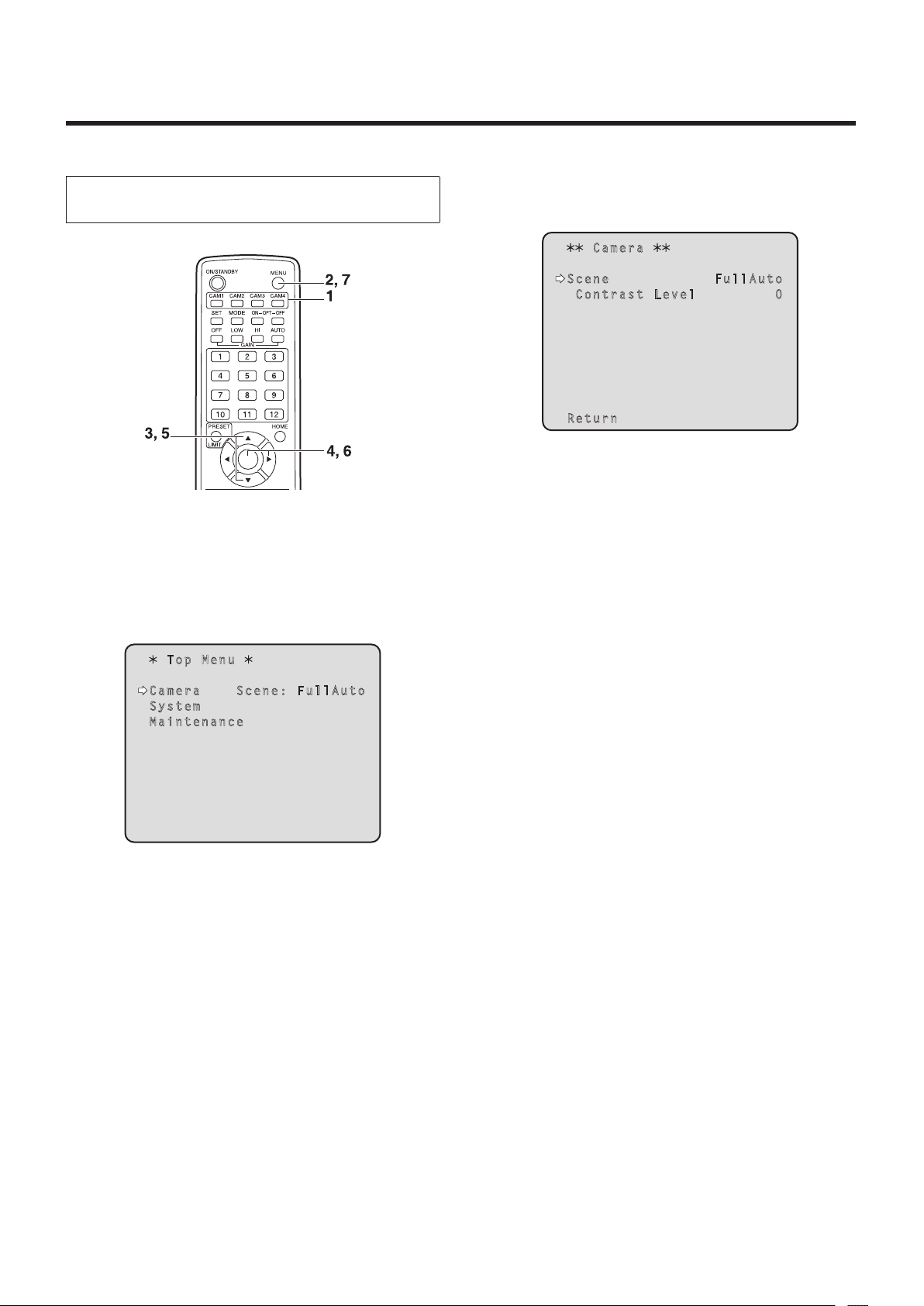
1 Press the [CAM1], [CAM2], [CAM3] or [CAM4]
button to select the unit.
2 Press the [MENU] button for 2 seconds.
The Top Menu is displayed.
Top Me nu
Ca mer a S cen e: F ul l Au t o
Sy ste m
Ma int ena nce
4 Press the [] button.
The “Camera” sub‑menu is displayed on the monitor.
Ca m er a
Sc e ne F ul l Au t o
C o nt r as t L e ve l 0
Re t ur n
5 Press the [] or [] button to bring the cursor
to “Scene”.
6 Press the [] button.
The shooting mode blinks.
7 Press the [] or [] button to select the
shooting mode (FullAuto, Manual1, Manual2 or
Manual3) to be used, and press the [] button
to enter the selection.
8 Press the [MENU] button for 2 seconds.
The menu display is exited.
3 Press the [] or [] button to bring the cursor
to “Camera”.
10
Page 11

Selecting the shooting modes (scene files)
When performing the operations using the controller
When the AW‑RP655 is connected:
1 Press the [1], [2], [3], [4] or [5] button of
[CONTROL/PREVIEW MONITOR OUT SEL].
2 Press the [MENU] button.
The display on the LCD panel of the AW‑RP655
switches to the menu mode.
3 Turn the jog dial (main).
Display “CAMERA SETTING” on the LCD panel.
4 Press the [OK] button.
Display “OPEN CAMERA MENU? OK Key” on the
LCD panel.
5 Press the [OK] button again.
The Top Menu is displayed on the monitor.
Top Me nu
Ca mer a S cen e: F ul l Au t o
Sy ste m
Ma int ena nce
8 Turn the jog dial (main) to bring the cursor to
“Scene”, and then press the jog dial (main) to
start the shooting mode blinking.
9 Turn the jog dial (main) to select the shooting
mode to be used, and press the jog dial (main)
to enter the selection.
10
Press the [MENU] button or [R/B GAIN/PED]
button.
The menu display is exited.
When the AW‑RP555 is connected:
1 Press the [1], [2], [3], [4] or [5] button of
[CONTROL] to select the unit.
2 Press the [1], [2], [3] or [USER] button of
[SCENE FILE] to select the shooting mode.
6 Turn the jog dial (main) to bring the cursor to
“Camera”.
7 Press the jog dial (main).
The “Camera” sub‑menu is displayed on the monitor.
Ca m er a
Sc e ne F ul l Au t o
C o nt r as t L e ve l 0
Re t ur n
Shooting mode [SCENE FILE] button
Manual1 [1]
Manual2 [2]
Manual3 [3]
FullAuto [USER]
When the AW‑RP50 is connected:
Refer to the Operating Instructions of the controller.
11
Page 12
Shooting
When performing the operations
using the wireless remote control
Changing the camera’s direction
Moving the camera toward the left or right (panning):
Press the [] or [] button.
Moving the camera up or down (tilting):
Press the [] or [] button.
Moving the camera diagonally:
Press the [] or [] button and [] or [] button at
the same time.
Returning the camera to the reference position:
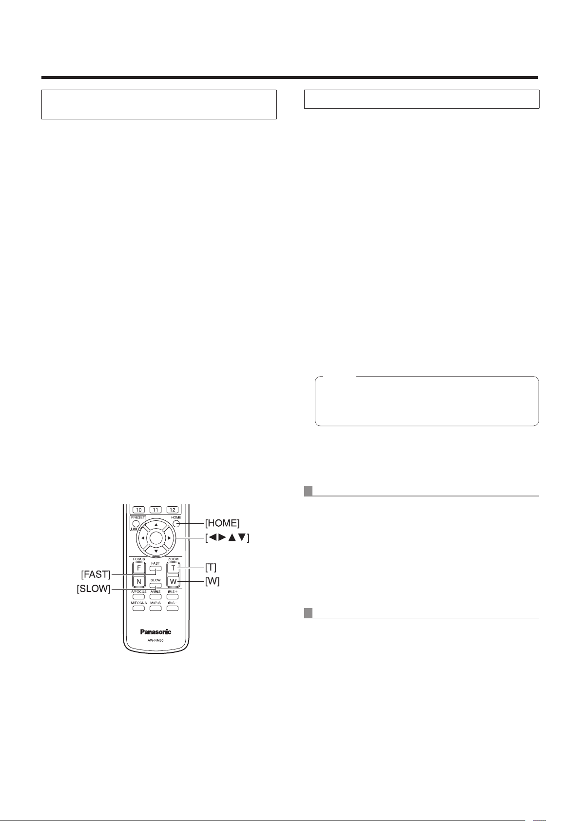
Press the [HOME] button for 2 seconds.
Using the zoom function
Zooming in (the subject becomes magnified in size):
Press the [T] button of [ZOOM].
Zooming out (the subject becomes reduced in size):
Press the [W] button of [ZOOM].
Switching the direction or zoom speed
Changing the direction or zoom at high speed:
Press the [FAST] button.
When performing the operations using the controller
Changing the camera’s direction
Moving the camera toward the left or right (panning):
Tilt the [PAN/TILT] lever toward L or R.
Moving the camera up or down (tilting):
Tilt the [PAN/TILT] lever toward UP or DOWN.
Moving the camera diagonally:
Tilt the [PAN/TILT] lever diagonally.
Returning the camera to the reference position:
If the controller has a [HOME] button, press the
[HOME] button.
Using the zoom function
Zooming in (the subject becomes magnified in size):
Tilt the [ZOOM] lever toward the TELE direction.
Zooming out (the subject becomes reduced in size):
Tilt the [ZOOM] lever toward the WIDE direction.
Note
The indicator displays of the AW‑RP655 are
indicators that show the positions of the optical
zoom so they will not work for electronic zooming.
Changing the direction or zoom at low speed:
Press the [SLOW] button.
The lens focus control speed is also changed at the same
time.
Changing the direction or zoom speed
AW‑RP655 and AW‑RP555
1 Press the [SPEED] button.
Each time the [SPEED] button is pressed, the control
speed is switched between the high speed (the button’s
lamp is off) and low speed (the button’s lamp is lighted).
The lens focus control speed is also changed at the
same time.
AW‑RP50
Refer to the Operating Instructions of the controller.
12
Page 13

What to do when encountering problems in the basic shooting operations
If the trouble is not resolved by taking the action suggested
below, refer to “Troubleshooting” (page 36 in the <Basics>).
When performing the operations
using the wireless remote control
The unit does not move.
Press the [CAM1], [CAM2], [CAM3] or [CAM4] button to
select the unit which is to be operated.
If only one unit is being used, it is normally selected using
the [CAM1] button.
If the unit’s status display lamp is off or lights up orange, it
means that the unit’s power is not on.
Refer to “How to turn the power on and off” (page 7), and
turn on the power.
If the unit’s status display lamp does not blink even
when the wireless remote control is operated near the
unit’s wireless remote control signal light‑sensing area, it
means that the wireless remote control’s batteries have
run down.
Replace the batteries.
Multiple color bands (color bars) are displayed.
Press the [MODE] button to switch to the camera picture.
When performing the operations using the controller
The unit does not move.
Select the unit to be operated by following the procedure
below.
When the AW‑RP655 is connected:
Press the [1], [2], [3], [4] or [5] button of [CONTROL/
PREVIEW MONITOR OUT SEL].
When the AW‑RP555 is connected:
Press the [1], [2], [3], [4] or [5] button of [CONTROL].
When the AW‑RP50 is connected:
Refer to the Operating Instructions of the controller.
If the [OPERATE] lamp on the controller is off, it means
that the power of the controller is not on.
If the unit’s status display lamp is off or lights up orange, it
means that the unit’s power is not on.
Refer to “How to turn the power on and off” (page 7), and
turn on the power.
The menu screen is displayed.
Press the [MENU] button for 2 seconds to exit the menu.
The lens focus is not adjusted automatically.
Press the [A/FOCUS] button to switch to auto focusing.
The camera picture is too light or too dark.
1. Press the [A/IRIS] button to switch automatically to the
lens iris adjustment.
2. Press the [AUTO] button of [GAIN] to switch
automatically to the gain adjustment.
Something is wrong with the coloring of the
camera pictures.
Refer to “Auto tracking white adjustment (ATW)” (page 24),
and switch to “ATW”.
The camera menus are not displayed.
When color bar signals are output, the camera menus are
not displayed with composite signals.
To operate the camera menus with composite signals, set
the color bar display to OFF.
Multiple color bands (color bars) are displayed.
Press the [MODE] button to switch to the camera picture.
The menu screen is displayed.
Press the [MENU] button to exit the menu.
The lens focus is not adjusted automatically.
Press the [EXT(AF)] button to switch to auto focusing.
The camera picture is too light or too dark.
1. Press the [IRIS] button several times to turn on its lamp,
and switch the lens iris adjustment to auto.
2. Press the [GAIN] button several times to turn on its lamp,
and switch the gain adjustment to auto.
Something is wrong with the coloring of the
camera pictures.
Refer to “Auto tracking white adjustment (ATW)” (page 24),
and switch to “ATW”.
The camera menus are not displayed.
When color bar signals are output, the camera menus are
not displayed with composite signals.
To operate the camera menus with composite signals, set
the color bar display to OFF.
13
Page 14

More advanced operations
Manual shooting (see pages 15 to 18)
Manual adjustment of focus
Manual adjustment of iris
Manual adjustment of shutter speed
Manual adjustment of gain
Preset memories (see pages 19 to 21)
Up to 100 settings for the camera direction (panning and
tilting), zoom, focus, iris, gain up and white balance can
be registered in the preset memories, and called.
The number of settings that can be registered and
called depends on the type of wireless remote control
(12 settings) or controller that is used for operation.
White balance adjustment
(see pages 22 to 24)
This adjustment is performed to express the white
accurately. Its setting also has an effect on the color tones
of the entire screen.
It must be performed when using the unit for the first
time or when the unit has not been used for a prolonged
period.
It must be performed when the lighting conditions or
brightness has changed.
Once the white balance has been attained, no further
adjustment is required provided that the unit is going to
be used under the same conditions.
Black level (master pedestal) adjustment
(see pages 25 to 26)
This adjustment is performed to align the black level
(pedestal level) of a multiple number of cameras.
Ask your dealer to perform this adjustment.
Genlock adjustment (AW‑HE50S only)
(see pages 27 to 29)
This adjustment is performed to achieve phase alignment
by applying external synchronization (genlock) when a
multiple number of cameras will be used or when the unit
will be used in combination with other devices.
Ask your dealer to perform this adjustment.
14
Page 15

Manual shooting
Manually adjusting the focus
The lens focus can be adjusted manually.
When the AW‑RP555 is connected:
When performing the operations
using the wireless remote control
1 Press the [M/FOCUS] button to switch the
focus to manual adjustment.
2 Press the [F] or [N] button of [FOCUS], and
adjust the focus.
When the [F] button is pressed, the focus moves further
away (far); conversely, when the [N] button is pressed, it
moves nearer (near).
The speed of focusing and other adjustments can
be switched to fast or slow by pressing the [FAST] or
[SLOW] button, respectively.
3 If necessary, press the [A/FOCUS] button to
return the focus to the automatic adjustment.
When performing the operations using the controller
When the AW‑RP655 is connected:
1 Press the [EXT(AF)] button to switch the focus
to manual adjustment.
1 Press the [EXT(AF)] button to switch the focus
to manual adjustment.
2 Adjust the focus manually by tilting the
[FOCUS] lever.
Furthermore, every time the [SPEED] button is pressed,
the speed of the focusing and other adjustments can be
switched to fast or slow.
3 If necessary, press the [EXT(AF)] button to
return the focus to the automatic adjustment.
When the AW‑RP50 is connected:
Refer to the Operating Instructions of the controller.
Note
When the focus is set to manual, the subject may
go out of focus during panning, tilting or zooming.
Therefore, the unit comes with a function which
compensates for this. (Focus compensation during
zooming function: Focus ADJ With PTZ.)
This function was set to ON at the factory.
If the function has been set to OFF, either adjust the
focus, as required, after zooming or set the focus to
auto. (See page 46 and page 65.)
2 Adjust the focus manually by turning the dial
above the lighted [FOCUS] lamp whether it
is the lamp of the [PAN/TILT] lever or [ZOOM]
lever.
Furthermore, every time the [SPEED] button is pressed,
the speed of the focusing and other adjustments can be
switched to fast or slow.
3 If necessary, press the [EXT(AF)] button to
return the focus to the automatic adjustment.
15
Page 16
Manual shooting
Manually adjusting the iris
The lens iris can be adjusted manually.
When the AW‑RP555 is connected:
When performing the operations
using the wireless remote control
1 Press the [M/IRIS] button to switch the iris to
manual adjustment.
2 Adjust the iris using the [IRIS +] or [IRIS –]
button.
Press the [IRIS +] button to adjust the lens iris in the
opening direction; conversely, press the [IRIS –] button
to adjust the lens iris in the closing direction.
3 If necessary, press the [A/IRIS] button to return
the iris to the automatic adjustment.
When performing the operations using the controller
1 Press the [IRIS] button to turn off its lamp and
switch to manual adjustment.
2 Turn the [LEVEL] dial of [IRIS] to adjust the iris
manually.
The position of the [LEVEL] dial does not represent an
absolute value. This is why the brightness may differ
from one camera to another even when the dial is set to
the same position.
3 If necessary, press the [IRIS] button to turn on
its lamp and switch to automatic adjustment
in order to return the iris to automatic
adjustment.
When the AW‑RP50 is connected:
Refer to the Operating Instructions of the controller.
When the AW‑RP655 is connected:
1 Press the [IRIS] button several times to turn
off the button’s lamp and switch to manual
adjustment.
2 Adjust the iris manually by turning the dial
above the lighted [IRIS] lamp whether it is the
lamp of the [PAN/TILT] lever or [ZOOM] lever.
3 If necessary, press the [IRIS] button several
times and turn on its lamp to return the iris to
the automatic adjustment.
16
Page 17

Manual shooting
Manually adjusting the shutter speed
The shutter speed can be set using two methods. One is
a method that specifies the time (where a time such as
1/250 sec. is designated), and the other is a method that
specifies the frequency (where synchro scan, 60.24 Hz, etc.
is designated).
When shooting a TV screen or PC monitor screen, the
horizontal noise generated when the screen is shot can
be minimized by adjusting the frequency to the screen
frequency using synchro scan.
When performing the operations
using the wireless remote control
Perform the adjustments on the Camera menu.
For further details, refer to the [Shutter Mode] and
[Step/Synchro] items on page 40.
When performing the operations using the controller
The procedure is the same as for “When performing the
operations using the wireless remote control” in “Basic
operations” (pages 30 to 37).
How to set the shutter speed using the AW‑RP555
1 With the [MEMORY] button still held down,
press the [SHUTTER] button.
The [PRESET] [1] to [5] and [6] to [10] buttons blink
alternately.
2 Press one of the [1] to [8] buttons or the
[10] [PRESET] button — whichever button
corresponds to the shutter speed which is to
be set.
Any of the shutter speeds in the table below can be set.
[1] [2] [3] [4] [5]
1/100 1/250 1/500 1/1000 1/2000
[6] [7] [8] [10]
1/4000 1/10000 Synchro Scan OFF
Any change in the shutter speed is reflected the next
time the [SHUTTER] button is pressed and its lamp
is turned on.
When OFF is selected, the shutter will not operate
even when the [SHUTTER] button is pressed.
Select the synchro scan setting on the menu.
The shutter speed setting performed here is stored in
the memory even when the power of the AW‑RP555
is turned off.
When the AW‑RP555 is connected:
1 Press the [SHUTTER] button and turn its lamp
on.
The shutter speed set ahead of time is selected.
2 If necessary, press the [SHUTTER] button and
turn its lamp off in order to return the shutter
to the OFF setting.
For further details, refer to the Operating Instructions of the
AW‑RP555.
17
Page 18
Manual shooting
Manually adjusting the gain
There are two ways to adjust the gain. One way involves
using the buttons on the wireless remote control or
controller; the other way involves using the Camera menu or
Web setting.
The gain can be adjusted more precisely using the Camera
menu or Web setting.
For further details, refer to the [Gain] item on page 40 and
page 59.
Note
When adjusting the gain, the light quantity may
change suddenly (causing the image output to be
subjected to a shock).
When performing the operations
using the wireless remote control
1 Press the [OFF], [LOW] or [HI] button.
These buttons enable the gain increase to be selected
in three steps.
[LOW] is used to select 9 dB; [HI] is used to select
18 dB.
When the AW‑RP555 is connected:
1 Press the [GAIN] button to turn off its lamp.
Each time this button is pressed, one of the three gain
increase amounts can be selected in sequence.
The current status is displayed as follows.
[MANU]
[L] lamp
0 dB Off Off Off
LOW Lighted Off Off
HIGH Off Lighted Off
AUTO Off Off Lighted
Other Lighted Lighted Off
[MANU]
[H] lamp
[GAIN]
button
2 If necessary, press the [GAIN] button several
times and turn on its lamp in order to return
the gain to the automatic adjustment (AGC).
When the AW‑RP50 is connected:
2 If necessary, press the [AUTO] button in order
to return the gain to the automatic adjustment
(AGC).
When performing the operations using the controller
When the AW‑RP655 is connected:
1 Press the [GAIN] button to turn off its lamp,
and then switch to manual adjustment.
The preset gain increase amount is now selected.
For further details on the gain increase amount setting,
refer to the Operating Instructions of the AW‑RP655.
2 If necessary, press the [GAIN] button and turn
on the button in order to return the gain to the
automatic adjustment (AGC).
Refer to the Operating Instructions of the controller.
In any case, the maximum gain of the automatic adjustment
can be set by the menu.
For further details, refer to the [AGC Max Gain] item on
page 40 and page 59.
18
Page 19

Preset memories
This unit enables up to 100 settings for the camera direction
(panning and tilting), zoom, focus, iris, gain and white
balance to be registered in its preset memories, and called.
However, the number of settings that can be registered and
called depends on the type of wireless remote control or
controller that is used for operation.
The operating mode (manual or auto setting) is not
registered for the focus and iris settings.
The current focus and iris values are registered.
The focus and iris values can be recalled only when the
manual settings are applicable.
AWB A, AWB B or ATW is registered as the white
balance setting. The values selected when AWB was
established are recalled as the adjustment values of
AWB A or AWB B.
The AWB Mode (ATW, AWB A or AWB B) stored using
the AW‑RP655 are recalled only when the AW‑RP655 is
connected.
Notes
When there is a large difference in the environmental
temperature between the time of registration and the
time the setting is called, displacement of the preset
position may occur.
If displacement occurs, perform registration again.
While preset settings are being called, it is not
possible to perform manual operations such as
panning, tilting, zooming or iris adjustments.
If, when one set of preset settings has been called,
another set of preset settings is then called, the first
set of preset settings which have been called will take
precedence.
When performing the operations
using the wireless remote control
Twelve settings (preset No.1 to No.12) can be registered and
called using the wireless remote control.
The [1] to [12] buttons correspond to the unit’s preset
memories No.1 to No.12.
Registering the settings in the preset memories
1 Display the picture to be shot on the monitor.
Operate the pan, tilt or zoom buttons to determine the
camera angle.
Adjust the focus, iris, gain and white balance if they
need to be adjusted.
2 While holding down the [PRESET] button,
press the button corresponding to the preset
memory number.
If a preset memory number with an already
registered setting has been selected, the existing
setting will be erased and replaced with the new one.
Calling the settings of the preset memories
1 Press the button in which the preset memory
setting has been registered.
19
Page 20

Preset memories
When performing the operations using the controller
When the AW‑RP655 is connected:
Up to 50 settings can be registered and called.
The [1] to [50] buttons of [TRACING/PRESET MEMORY]
correspond to the unit’s preset memories No.1 to No.50.
Registering the settings in the preset memories
1 Set to the preset memory mode.
Press the [TR/PSET] button to turn off its lamp.
2 Set to the memory recording mode.
Press the [M.LOCK] button to turn off its lamp.
3 Display the picture to be shot on the monitor.
Operate the [PAN/TILT] lever and [ZOOM] lever to
determine the camera angle.
Adjust the focus, iris, gain and white balance if they
need to be adjusted.
4 Hold down the [MEMORY] button.
The buttons among the [1] to [50] buttons of [TRACING/
PRESET MEMORY] in which settings can be registered
now start blinking in sequence.
Preset memory settings cannot be registered in
buttons whose lamps are off (since they contain
tracing memory settings).
5 With the [MEMORY] button still held down,
press the button of the preset memory number
in which the setting is to be registered.
Calling the settings of the preset memories
1 Set to the preset memory mode.
Press the [TR/PSET] button to turn off its lamp.
2 Press the button among the [1] to [50] buttons
of [TRACING/PRESET MEMORY] in which the
desired setting was registered.
Erasing preset memory settings
1 Set to the preset memory mode.
Press the [TR/PSET] button to turn off its lamp.
2 Set the memory recording mode.
Press the [M.LOCK] button to turn off its lamp.
3 Hold down the [RESET] button.
The buttons among the [1] to [50] buttons of [TRACING/
PRESET MEMORY] whose settings can be erased now
start blinking in sequence.
The settings for the buttons whose lamps are off
cannot be erased (since they contain tracing memory
settings).
4 With the [RESET] button still held down, press
the button of the preset memory number
whose setting is to be erased.
20
Page 21

Preset memories
When the AW‑RP555 is connected:
Up to 10 settings can be registered and called.
The [1] to [10] buttons of [PRESET] correspond to the unit’s
preset memories No.1 to No.10.
Registering the settings in the preset memories
1 Display the picture to be shot on the monitor.
Operate the [PAN/TILT] lever and [ZOOM] lever to
determine the camera angle.
Adjust the focus, iris, gain and white balance if they
need to be adjusted.
2 Hold down the [MEMORY] button.
The buttons among the [1] to [10] buttons of [PRESET]
in which settings can be registered now start blinking in
sequence.
3 With the [MEMORY] button still held down,
press the button of the preset memory number
in which the setting is to be registered.
When the AW‑RP50 is connected:
Refer to the Operating Instructions of the controller.
Calling the settings of the preset memories
1 Press the button among the [1] to [10] buttons
of [PRESET] in which the desired setting was
registered.
21
Page 22
White balance adjustment
White balance adjustment
In order for the white to be reproduced accurately, the ratio
between the three primary colors (RGB) is adjusted. If the
white balance has shifted out of adjustment, not only will the
white be reproduced poorly but the color tones of the entire
screen will also be degraded.
This adjustment must be performed when using the
unit for the first time or when the unit has not been
used for a prolonged period.
It must be performed when the lighting conditions or
brightness has changed.
Automatic adjustment
(AWB: AWB A or AWB B)
1 Shoot a white subject (such as a white wall or
handkerchief) so that it fills the screen.
Do not shoot shiny or very bright objects.
Either AWB (automatic white balance adjustment) which
initiates automatic adjustment when the AWB button on the
controller has been pressed or ATW (automatic tracking
white balance adjustment) which constantly adjusts the
white balance can be selected for adjustment purposes.
The results of the AWB adjustment can be stored in two
memories, A and B, when “AWB A” or “AWB B” has been
selected for the white balance.
Once the white balance has been adjusted when the
unit is used with the same settings and under the same
conditions, its setting is completed simply by selecting a
menu setting or pressing a button on the controller.
There is no need to set it again.
Once a new setting is entered, the previous setting will be
erased.
Use the two memories to store settings corresponding to
different shooting conditions.
When performing the operations
using the wireless remote control
Steps
2 through 8 represent the procedure for selecting
the “AWB A” or “AWB B” memory. They need not be taken
if a selection has already been made.
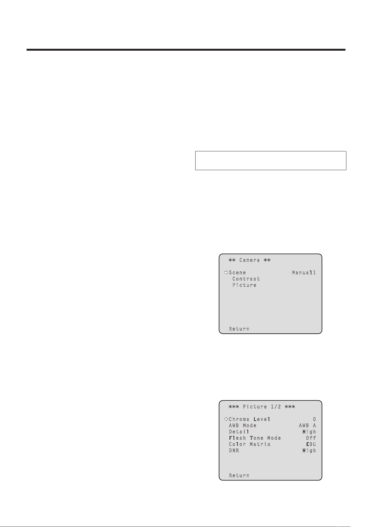
2 Select Manual1, Manual2 or Manual3 as the
shooting mode by following the procedure in
“Selecting the shooting modes (scene files)
(page 10).
Ca m er a
Sc e ne Ma n ua l 1
C o nt r as t
P i ct u re
Re t ur n
3 Press the [] or [] button to bring the cursor
to “Picture”.
4 Press the [] button.
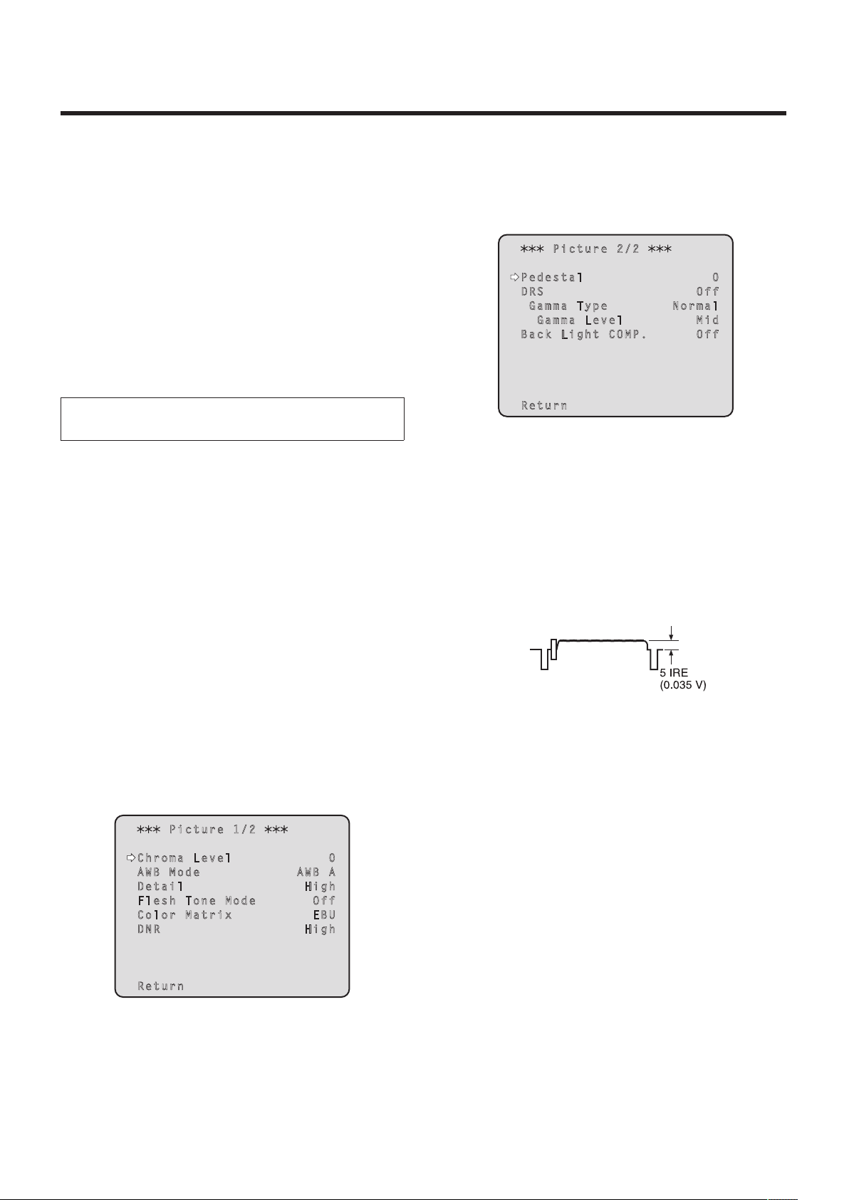
The “Picture 1/2” sub‑menu is displayed.
P ict ure 1/ 2
Ch rom a L eve l 0
AW B M ode A WB A
De tai l Hi g h
Fl esh To ne Mod e O f f
Co lor Ma tri x E B U
DN R Hi g h
Re tur n
22
Page 23
White balance adjustment
5 Press the [] or [] button to bring the cursor
to “AWB Mode”.
6 Press the [] button.
“AWB Mode” starts blinking.
7 Press the [] or [] button to change the AWB
mode to be used to “AWB A” or “AWB B”, and
press the [] button to enter the selection.
8 Press the [MENU] button for 2 seconds.
The menu display is exited.
9 Press the [SET] button for 2 seconds.
The auto white balance adjustment (AWB) is performed,
and the white balance setting is entered.
The white balance cannot be adjusted when color
bars are displayed. Press the [MODE] button to
switch to the camera picture.
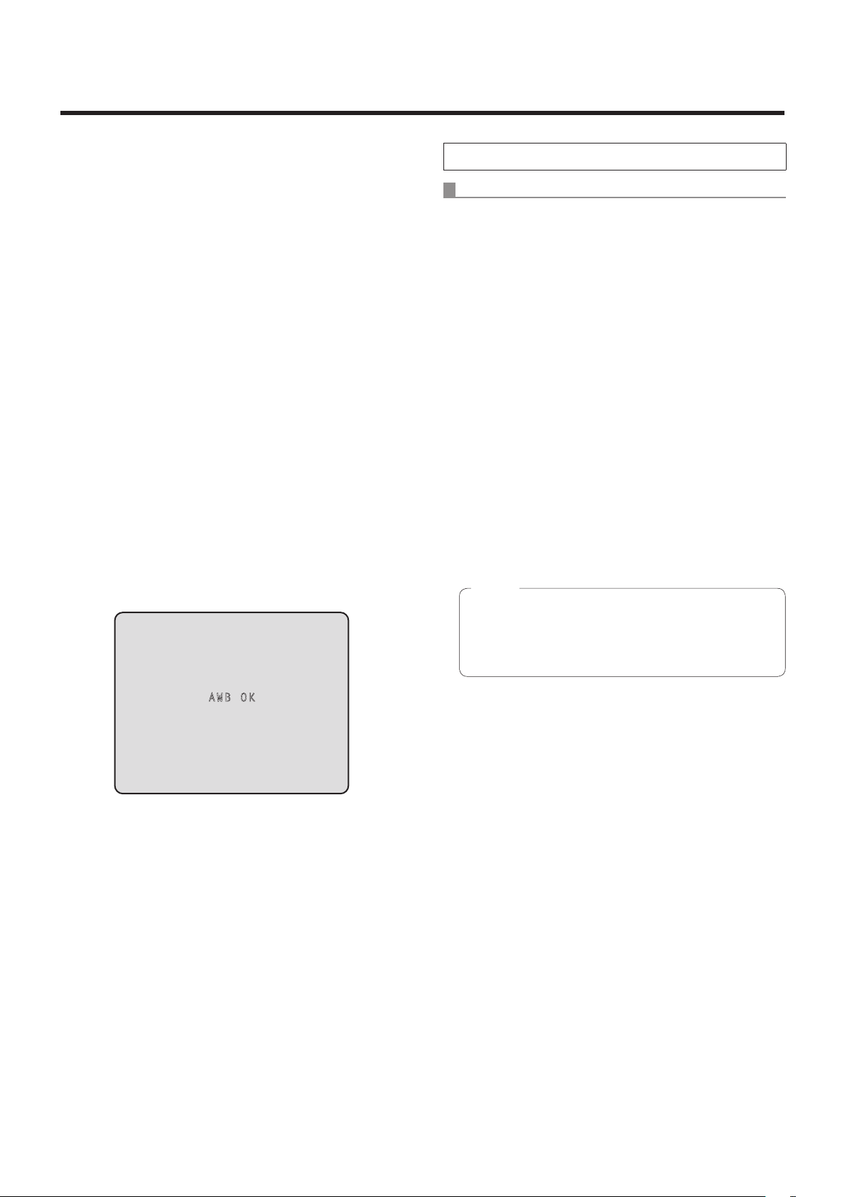
When the white balance adjustment is completed
successfully, “AWB OK” appears in the center of the
screen.
When performing the operations using the controller
When the AW‑RP655 or AW‑RP555 is connected:
2 Press the [A] button or [B] button of [WHITE
BAL] to select “AWB A” or “AWB B” for the
white balance.
The selected button’s lamp lights.
The white balance setting is not entered if “ATW” has
been selected.
3 Press the [AWC] button.
The auto white balance adjustment (AWB) is executed,
and the white balance setting is entered.
The [AWC] button’s lamp blinks while the white balance
is being adjusted, and its lamp goes off when the
adjustment is completed successfully. Its lamp lights if
the white balance could not be adjusted.
If color bars have been selected (the [MODE] button
or [BAR/CAM] button’s lamp lights) or if ATW is
selected (the [ATW] button’s lamp lights), it means
that the [AWC] button is not working or that the auto
white balance adjustment has failed. (The button’s
lamp lights.)
Note
In the case of the AW‑RP655, even when it is not
possible to adjust the white balance, the [AWC]
button’s lamp will not light and after blinking it will
go off.
AW B O K
When the adjustment has failed, an error message
such as “OUT RANGE NG”, “HIGH LIGHT NG”,
“LOW LIGHT NG” or “ATW NG” is displayed.
23
Page 24

White balance adjustment
When the AW‑RP50 is connected:
Refer to the Operating Instructions of the controller.
Notes
White balance may not be correctly set if the lighting
of the object is too weak.
Since the unit has a built‑in memory, the set white
balance will remain in the memory even if power is
turned off. Therefore, it is not necessary to reset the
white balance if the color temperature of those objects
remains unchanged. However, it must be reset if the
color temperature changes, such as when you move
from indoors to outside, or vice versa.
Auto tracking white adjustment (ATW)
When the white balance adjustment is set to “ATW”, the
white balance continues to be adjusted automatically all
the time, and it is automatically corrected even when the
light source or color temperature has changed to produce
completely natural pictures.
This function works when “ATW” is selected instead of
“AWB A” or “AWB B” by following the steps for “Automatic
adjustment” in “White balance adjustment” (page 22).
Notes
ATW might not function properly when high brightness
light (ex. fluorescent lamp) beams into a screen.
White balance may not be accurately set if there is no
white object in the scene being shot.
The white balance may shift out of adjustment when
a different kind of light source such as sunlight or
fluorescent lighting applies.
24
Page 25
Black level (master pedestal) adjustment
Black level (master pedestal) adjustment
The black level can be adjusted when using a multiple
number of cameras including the unit. Ask your dealer to
perform this adjustment.
(Use an oscilloscope or waveform monitor for the
adjustment.)
Adjust the black level in accordance with the units and
devices used.
The black level can be adjusted only when Manual1,
Manual2 or Manual3 is selected as the shooting mode
(scene file).
When performing the operations
using the wireless remote control
1 Press the [M/IRIS] button.
Set the iris to the manual mode.
2 Press the [IRIS –] button.
The lens iris is stopped down.
3 Select Manual1, Manual2 or Manual3 by
following the procedure in “How to select the
shooting mode” (page 10) under “Selecting the
shooting modes (scene files)”.
6 Press the [] or [] button to move to the
“Picture 2/2” sub‑menu, and bring the cursor
to “Pedestal”.
P ict ure 2/ 2
Pe des tal 0
DR S O f f
G amm a T ype N o rm a l
Gam ma Lev el M i d
Ba ck Lig ht COM P . O f f
Re tur n
7 Press the [] button to start the “Pedestal”
value blinking.
8 Press the [] or [] button, change the
“Pedestal” value, and press the [] button to
enter the selection.
Adjust the black level to a value of approx. 5 IRE
(0.035 V).
4 Press the [] or [] button to bring the cursor
to “Picture”.
5 Press the [] button.
The “Picture 1/2” sub‑menu is displayed.
P ict ure 1/ 2
Ch rom a L eve l 0
AW B M ode A WB A
De tai l Hi g h
Fl esh To ne Mod e O f f
Co lor Ma tri x E B U
DN R Hi g h
Re tur n
9 Press the [MENU] button for 2 seconds.
The menu display is exited.
10
If necessary, press the [A/IRIS] button to adjust
the iris automatically.
25
Page 26

Black level (master pedestal) adjustment
When performing the operations using the controller
When the AW‑RP655 is connected:
1 Press the [IRIS] button several times to turn off
its lamp.
Set the iris to the manual ([MANU]) mode.
2 Turn the [FOCUS/IRIS] dial to stop down the
lens iris.
3 Press the [R/B GAIN/PED] button several
times so that the “PEDESTAL TOTAL” item is
displayed on the LCD panel.
4 Turn the jog dial (main) and adjust the black
level to 5 IRE (0.035 V).
5 If necessary, adjust the iris automatically.
Press the [IRIS] button several times to turn on
its lamp.
When the AW‑RP555 is connected:
1 Press the [IRIS] button several times to turn off
its lamp.
Set the iris to the manual ([MANU]) mode.
2 Turn the [LEVEL] dial of [IRIS] to stop down
the lens iris.
3 Follow the operation steps in “Basic
operations” (page 36), and use the menu to
perform the adjustment.
When the AW‑RP50 is connected:
Refer to the Operating Instructions of the controller.
26
Page 27
Genlock adjustment (AW‑HE50S only)
Genlock adjustment
The genlock adjustment is performed to achieve phase
alignment by applying external synchronization (genlock)
when a multiple number of cameras will be used or when
the unit will be used in combination with other devices.
This unit supports the BBS signal as the genlock signal.
Ask your dealer to perform this adjustment.
(Use a dual‑trace oscilloscope for the adjustment.)
(The genlock function is not available with the AW‑HE50H.)
Horizontal phase adjustment
Observe the waveforms of the external sync signal input
(black burst signal) and video signal output on the dual‑trace
oscilloscope, and use the wireless remote control or
controller to bring the horizontal phase into alignment.
External sync signal
input (black burst signal)
3 Press the [] button.
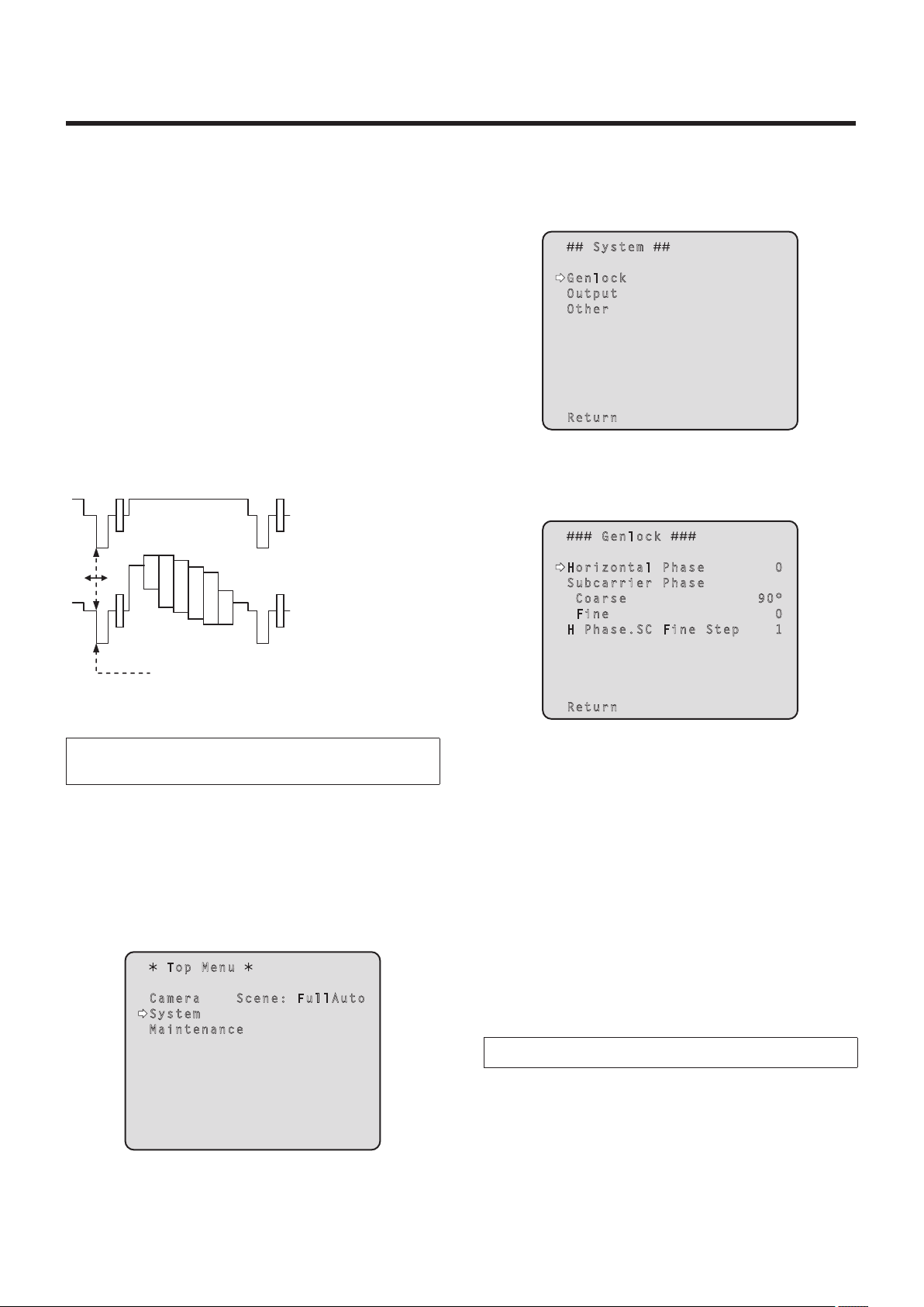
The “System” sub‑menu is displayed.
Sy ste m
Ge nlo ck
Ou tpu t
Ot her
Re tur n
4 Press the [] or [] button to bring the cursor
to “Genlock”, and press the [] button.
The “Genlock” sub‑menu is displayed.
G enl ock
Video signal output
Bring the horizontal phase into alignment.
When performing the operations
using the wireless remote control
1 Follow the operation steps in “Basic
operations” (page 32) to display the “Top
Menu”.
2 Press the [] or [] button to bring the cursor
to “System”.
Top Me nu
Ca mer a S cen e: F ul l Au t o
Sy ste m
Ma int ena nce
Ho riz ont al Pha se 0
Su bca rri er Pha se
C oar se 9 0 °
F ine 0
H Pha se. SC Fin e S t ep 1
Re tur n
5 Press the [] or [] button to bring the cursor
to “Horizontal Phase”, and press the []
button.
The “Horizontal Phase” value starts blinking.
6 Press the [] or [] button to change the
“Horizontal Phase” value, adjust the value
so that the horizontal phase is brought into
alignment, and press the [] button.
7 Press the [MENU] button for 2 seconds.
The menu display is exited.
When performing the operations using the controller
These operations can be performed using the camera
menus by following the operation steps in “Basic operations”
(pages 30 to 37).
27
Page 28

Genlock adjustment (AW‑HE50S only)
Color phase adjustment
The color phase adjustment must be performed if the
pictures are to be switched using a video switcher or other
device when the video output signals have been set as
composite signals.
It need not be performed when the video output signals
have been set as component signals.
The camera’s color phase is aligned with the program output
(split color bar output) signals of a color special effect device
or other color tones that will serve as the reference.
(The color phase can be adjusted more accurately if a
vectorscope is used for the adjustment.)
Color bar of camera
Split line
Color bar of special
effects generator
When performing the operations
using the wireless remote control
4 Press the [] button.
The “System” sub‑menu is displayed.
Sy ste m
Ge nlo ck
Ou tpu t
Ot her
Re tur n
5 Press the [] or [] button to bring the cursor
to “Genlock”, and press the [] button.
The “Genlock” sub‑menu is displayed.
G enl ock
Ho riz ont al Pha se 0
Su bca rri er Pha se
C oar se 9 0 °
F ine 0
H Pha se. SC Fin e S t ep 1
1 Press the [MODE] button.
The mode is switched to the color bar display.
2 Follow the operation steps in “Basic
operations” (page 32) to display the Top Menu.
3 Press the [] or [] button to bring the cursor
to “System”.
Top Me nu
Ca mer a S cen e: F ul l Au t o
Sy ste m
Ma int ena nce
Re tur n
6 Press the [] or [] button to bring the cursor
to “Coarse” or “Fine” of “Subcarrier Phase”,
and press the [] button.
The “Coarse” or “Fine” value starts blinking.
7 Press the [] or [] button to change the
“Coarse” or “Fine” value of “Subcarrier
Phase”, adjust the value so that the color
phase is brought into alignment, and press the
[] button.
8 Press the [MENU] button for 2 seconds.
The menu display is exited.
9 Press the [MODE] button.
The mode is switched to the camera picture display.
28
Page 29

Genlock adjustment (AW‑HE50S only)
When performing the operations using the controller
These operations can be performed using the camera
menus by following the operation steps in “Basic operations”
(pages 30 to 37).
To switch between “BAR” (color bar display) and “CAM”
(camera pictures), press the [MODE] or [BAR/CAM] button.
29
Page 30

Basic operations
Menus are displayed on the monitor when the unit’s settings
are to be selected.
The monitor is connected to the video signal output
connector.
The basic menu operations involve displaying sub‑menus
from the Top Menu items, and selecting settings on the
sub‑menus.
Some sub‑menus have menu items for performing more
detailed settings.
The menu operations are conducted using the wireless
remote control.
If a controller is connected, they can also be conducted
using the controller.
It may be necessary to upgrade the controller’s version in
order to support the AW‑HE50.
For further details, consult with your dealer.
Described below are the basic operations for changing the
menu item settings using the wireless remote control and
controller (AW‑RP655, AW‑RP555 or AW‑RP50).
Table of operations
Only the steps taken using the wireless remote
control will be described here for the operations
conducted to select and set the items.
For details of the operations conducted using the
controller, substitute “controller” for “wireless
remote control” when reading the basic operations.
Also, refer to the Operating Instructions of the
controller.
Menu operation
Selecting the
unit to be
operated
Displaying the
Top Menu
Selecting the
items
Displaying the
sub‑menus
Wireless remote
control
Press the [CAM1],
[CAM2], [CAM3] or
[CAM4] button.
Press the [MENU]
button for 2 seconds.
Press the [] or []
([] or []) button.
Press the [] button.
Controller
AW‑RP655 AW‑RP555 AW‑RP50
Press one of the [1] to [5]
buttons of [CONTROL/
PREVIEW MONITOR OUT
SEL].
1. Press the [MENU] button.
The display on the
AW‑RP655’s LCD panel
changes to the menu mode.
2. Turn the jog dial (main)
to display “CAMERA
SETTING” on the LCD
panel, and press the [OK]
button.
3. The scene selection menu
now appears on the LCD
panel so select the scene to
be set, and press the [OK]
button.
4. If the “OPEN CAMERA
MENU? OK Key”
message appears on the
LCD panel, press the [OK]
button again.
Turn the jog dial (main). Press the [YES] or [NO] button. Turn the F1 dial.
Press the jog dial (main). Press the [ITEM] button. Press the F1 dial.
Press one of the [1] to [5]
buttons of [CONTROL].
Press the [MENU] button for
2 seconds.
Press one of the [CAMERA
STATUS/SELECTION] buttons.
Press the [CAMERA OSD]
button for 2 seconds.
30
Page 31

Basic operations
Menu operation
Returning to the
previous menu
Changing the
settings
Canceling the
setting change
Exiting
the menu
operations
Wireless remote
control
With the cursor at
the [Return] position,
press the [] button.
With the cursor at the
item to be changed,
press the [] button to
start the item’s value
blinking.
Use the [], [], []
and [] buttons to
change the value, and
press the [] button to
enter the change.
While the setting
is blinking, press
the [MENU] button
quickly (for less than
2 seconds).
Press the [MENU]
button for 2 seconds.
AW‑RP655 AW‑RP555 AW‑RP50
With the cursor at the [Return]
position, press the jog dial
(main).
1. Press the jog dial (main) to
start the setting blinking.
2. Turn the jog dial (main) to
change the setting.
3. Press the jog dial (main) to
enter the setting (and stop
the blinking).
While the setting is blinking,
press the jog dial (R).
Press the [MENU] button or
[R/B GAIN/PED] button.
Controller
With the cursor at the [Return]
position, press the [ITEM]
button.
1. Press the [ITEM] button to
start the setting blinking.
2. Press the [YES] or [NO]
button to change the setting.
3. Press the [ITEM] button to
enter the setting (and stop
the blinking).
While the setting is blinking,
press the [MENU] button.
Press the [MENU] button for
2 seconds.
With the cursor at the [Return]
position, press the F1 dial.
1. Press the F1 dial to start the
setting blinking.
2. Turn the F1 dial to change
the setting.
3. Press the F1 dial to enter
the setting (and stop the
blinking).
While the setting is blinking,
press the [CAMERA OSD]
button.
Press the [CAMERA OSD]
button for 2 seconds.
Notes
Perform the menu operations and exit from the menus using the controller which displayed the Top Menu.
If a menu operation has been performed or a menu has been exited using another controller, first display the Top Menu
and exit from it using one controller, and then display the Top Menu and exit from it using the other controller.
The unit uses a different method to operate its menus from the one employed by the convertible cameras (except for the
AW‑HE870) and HD integrated cameras which have already been launched onto the market.
For details, refer to the Operating Instructions of the camera concerned.
31
Page 32

Basic operations
When performing the operations using the wireless remote control
1 Press the [CAM1], [CAM2], [CAM3] or [CAM4]
button to select the unit which is to be
operated.
2 Press the [MENU] button for 2 seconds.
The Top Menu is displayed.
8 Press the [] button.
The value of the item to be set is entered, and it stops
blinking.
9 After the setting has been completed, press
the [MENU] button for 2 seconds.
The menu display is exited.
3 Press the [] or [] button to bring the cursor
to the item to be selected.
Each time the [] or [] button is pressed, the cursor
moves.
The cursor can be moved in the same way using the
[] and [] buttons.
4 Press the [] button.
The sub‑menu of the selected item is displayed.
(Some sub‑menu items have a sub‑menu of their own.)
5 Press the [] or [] button to bring the cursor
to the item to be set.
Each time the [] or [] button is pressed, the cursor
moves.
The cursor can be moved in the same way using the
[] and [] buttons.
With the cursor at the “Return” position, press the []
button to return to the previous menu.
6 Press the [] button.
The value of the item to be set starts blinking.
7 Press the [] or [] button to change the
setting.
The setting can be changed in the same way using the
[] and [] buttons.
32
Page 33

Basic operations
Control exercised from the Multi‑Function Controller AW‑RP655
Each time the [MODE] button is pressed, the
setting is switched between CAM and BAR.
The [MODE] button lights up at the BAR setting.
This is used to switch between AUTO and
MANU for the gain. The [GAIN] button
lights when the AUTO setting is selected.
For switching WHITE BAL A,
B or ATW.
For executing AWB.
*1, *2
The unit does not have
an ABC function.
Jog dial (main)
When the LCD is in the gain adjustment
mode ([GAIN] button: MANU)
Select the desired gain setting from GAIN
0 dB to 18 dB. *4
When the LCD is in the gain adjustment
mode ([GAIN] button: AUTO)
Select the desired gain setting from AGC MAX
GAIN 6 dB, 12 dB or 18 dB.
When the LCD is in the pedestal adjustment
mode
Adjust the PEDESTAL TOTAL setting (–150 to
+150). *5
When the camera menu mode is established
Perform the camera menu operations.
These are used for menu operation.
Each time the [EXT(AF)]
button is pressed,
the focus setting is
switched between auto
focus and manual focus.
When auto focus is
selected, the [EXT(AF)]
button lights.
When the focus setting
is switched between
auto focusing and
manual focusing by the
camera, the resulting
status (lamp on or off)
will not be reflected in
the button.
This is used to acquire the statuses of the camera
and synchronize the data. *3
*1: The AWC switch indicator blinks while the white
balance is being adjusted. It goes off whether the
AWB adjustment is completed successfully or
unsuccessfully.
*2: The switch lights without AWB being executed
when the white balance mode of the main unit is
ATW, or when the Color Bar is being displayed.
*3: SCENE FILE, CAM/BAR, and GAINUP of each
SCENE, as well as the W/B MODE and PED statuses
are synchronized.
Jog dial (R)
When the LCD is in the camera menu mode
Press the jog dial (R) to cancel the setting
change.
*4: With this unit, the gain setting is reflected in
increments of 3 dB in the control.
*5: With this unit, the setting is reflected in increments
of 15 dB in the control.
On the camera menu, the setting is adjusted in
range from –10 to +10.
For selecting the cameras
to be operated.
33
Page 34

Basic operations
Procedure for camera menu operation (AW‑RP655)
1 Press one of the [1] to [5] buttons of
[CONTROL/PREVIEW MONITOR OUT SEL] to
select the unit which is to be operated.
2 Press the [MENU] button to set the LCD panel
display to the menu mode.
3 Turn the jog dial (main) until CAMERA
SETTING appears, and press the [OK] button.
CAMERA SETTING
OK Key
4 When the scene selection menu has appeared
on the LCD panel, select the scene to be set,
and press the [OK] button.
SCENE HALOGEN
OK Key
The scene names displayed on the LCD panel correlate
with the scene files of the AW‑HE50 as shown below.
AW‑RP655 display AW‑HE50 scene file
HALOGEN Manual1
FLUORESCENT Manual2
OUTDOOR Manual3
USER FullAuto
6 Turn the jog dial (main) to select menu items of
the AW‑HE50 and change the data.
Turn the jog dial (main) when the cursor is to be moved
up or down or the settings are to be changed.
Press it when moving to the menu at the next lower
hierarchical level or changing a setting at the very
bottom hierarchical level.
7 Press the [MENU] button for 2 seconds to exit
the camera menu.
Notes
Genlock is set using the camera menu for the
AW‑HE50.
It may be necessary to upgrade the software version
in order to operate an AW‑HE50 from an AW‑RP655.
Ask your dealer for details.
5 When the following message appears on the
LCD panel, press the [OK] button again.
OPEN CAMERA MENU ?
OK Key
The menu of the AW‑HE50 is displayed on the monitor.
34
Page 35

Basic operations
Control exercised from the Multi Hybrid Control Panel AW‑RP555
Each time the [GAIN] button is
pressed, the setting is switched in
the sequence of GAIN AUTO
0dB L (9dB) H (18dB), and the
mode is displayed by the LEDs as
shown below.
[ON: LED lighted; OFF: LED off]
AUTO ON OFF OFF
0dB OFF OFF OFF
LOW OFF ON OFF
HIGH OFF OFF ON
Others OFF ON ON
Each time the [MODE] button is
pressed, the setting is switched
between CAM and BAR.
The [MODE] button lights up at the
BAR setting.
For selecting the cameras to be
operated.
Shutter mode selection
Each time this button is pressed, one of the
shutter modes set by the controller or “shutter
OFF” is selected.
The [SHUTTER] button lights up in all modes
except shutter OFF.
The shutter mode settings established by the
[PRESET] buttons are as follows.
GAIN
button
MODE
1/100 PRESET1 1/10000 PRESET7
1/250 PRESET2
1/500 PRESET3
1/1000 PRESET4 ELC PRESET9
1/2000 PRESET5 OFF PRESET10
1/4000 PRESET6
MANU L
PRESET
No.
LED
SYNCHRO‑
MANU H
LED
MODE
SCAN
For executing AWB. *1, *2
PRESET
No.
PRESET8
For switching WHITE BAL A, B or ATW.
The unit does not have
an ABC function.
For switching the SCENE file
(FullAuto, Manual1 to 3).
For operating the camera menus.
MENU: This operates in the same
way as MENU on the
camera.
ITEM: This operates in the same
way as ENTER on the
camera.
YES: This operates in the same
way as UP on the camera.
NO: This operates in the same
way as DOWN on the
camera.
Each time the [EXT(AF)] button
is pressed, the focus setting is
switched between auto focus and
manual focus.
When auto focus is selected, the
[EXT(AF)] button lights.
When the focus setting is
switched between auto focusing
and manual focusing by the
camera, the resulting status (lamp
on or off) will not be reflected in
the button.
*1: The lamp of the AWC switch flashes while
automatic white balance is being executed.
When AWB is completed successfully, the lamp
goes off; when it is not completed successfully, it
lights up.
*2: The switch lights without AWB being executed
when the white balance mode of the main unit is
ATW, or when the Color Bar is being displayed.
35
Page 36

Basic operations
Procedure for camera menu operation (AW‑RP555)
1 Press one of the [1] to [5] buttons of
[CONTROL] to select the unit which is to be
operated.
2 Press the [MENU] button of the AW‑RP555 for
2 seconds.
The camera menu of the AW‑HE50 is displayed on the
monitor.
3 Perform one of the following steps to select
the menu item.
If the [YES] button is pressed, the selection item moves
up; if the [NO] button is pressed, it moves down.
4 Press the [ITEM] button.
The value of the item to be set starts blinking.
5 Press the [YES] or [NO] button to change the
setting.
Note
It may be necessary to upgrade the software version
in order to operate an AW‑HE50 from an AW‑RP555.
Ask your dealer for details.
6 After deciding on the setting, press the [ITEM]
button.
The value of the item to be set is entered, and it stops
blinking.
7 Press the [MENU] button for 2 seconds to exit
the camera menu.
36
Page 37

Basic operations
Control exercised from the Remote Camera Controller AW‑RP50
F1
POWER ALARM F1 CAMERA
1 2 3
R/B GAIN R/B PED
TELE
GAIN/PED
PAGEMENU F2 EXIT
6 7 8 9 10
DETAIL
DELETESTORE
ZOOM
WIDE
SCENE/MODE
PRESET MEMORY / MENU
1 2 3 4 5
CAMERA STATUS / SELECTION
AUTO
AWB/ABB4SHUTTER
F2
5
SYSTEMSETUPCAMERA
PTZ/FOCUS SPEEDFOCUS/PUSH OAF
HILOW
OSD
USER2USER1
PT ACTIVEAUTOIRIS
For operating the camera menus.
CAMERA OSD:
When this is pressed for
2 seconds, the selected camera
menu is displayed, overlapping
the camera output image.
When it is pressed for
2 seconds while a camera
menu is displayed, the menu is
cleared.
F1: Turn F1 to move the cursor up
or down on the camera menu or
change the setting.
Press it when moving to
the menu at the next lower
hierarchical level or changing
a setting at the very bottom
hierarchical level.
For selecting the cameras to be operated.
Procedure for camera menu operation (AW‑RP50)
1 Press one of the [CAMERA STATUS/
SELECTION] buttons to select the unit which
is to be operated.
2 Press the [CAMERA OSD] button of the
AW‑RP50 for 2 seconds.
The camera menu of the AW‑HE50 is displayed on the
monitor.
3 Turn the F1 dial to select the AW‑HE50 menu
item or change the data.
Turn the F1 dial to move the cursor up or down or
change the setting.
Press it to move to the menu at the next lower
hierarchical level or change a blinking setting at the
very bottom hierarchical level.
4 Press the [CAMERA OSD] button for
2 seconds to exit the camera menu.
37
Page 38

Setting the menu items
Setting the menu items
When the unit’s settings are to be selected, the menus are
displayed on the monitor.
The monitor is connected to the video signal output
connector.
The basic menu operations involve displaying sub‑menus
from the Top Menu items, and selecting settings on the
sub‑menus.
Some sub‑menus have menu items for performing more
detailed settings.
For details on the basic operations to display the menus
and change the items using the wireless remote control or
controller (AW‑RP655, AW‑RP555 or AW‑RP50), refer to
pages 30 to 37.
The “
” and “ ” marks in the menu titles indicate the
hierarchical level of the menu currently displayed.
For instance, “
hierarchical level whereas “
“
level is now displayed.
Menu items accompanied by a “
which is stored on a scene by scene basis; menu items
accompanied by a “
together for one camera regardless of the scenes.
” indicate that the second hierarchical
” mark indicate data which is stored
” indicates the first
” and
” mark indicate data
Top Menu
Top Me nu
Ca mer a S cen e: F ul l Au t o
Sy ste m
Ma int ena nce
Camera
Select this to open the camera menu relating to the
camera images.
System
Select this to display the System menu used to adjust the
genlock (external synchronization) phase or establish the
camera output image settings.
Maintenance
Select this to display the Maintenance menu used to
check the camera’s firmware version or initialize its
settings.
Note
The Top Menu does not have a “Return” setting.
To close the menu screen, use the controller to
perform the operation to close the menu screen.
For details, refer to pages 30 to 37.
38
Page 39

Setting the menu items
Camera screen
(when FullAuto is selected)
This menu is used for the camera image settings.
Ca m er a
Sc e ne F ul l Au t o
C o nt r as t L e ve l 0
Re t ur n
Scene
[FullAuto, Manual1, Manual2, Manual3]
Selected here is the shooting mode that matches the
shooting situation.
Select the mode which best suits the prevailing shooting
conditions and the user’s preferences.
FullAuto: In this mode, the optimum settings and
adjustments for the shooting conditions at
hand are automatically established.
When “FullAuto” has been selected, the
detailed setting and adjustment menus
are not displayed.
Manual1 to 3: In these modes, the detailed settings and
adjustments are established manually to
match the prevailing shooting conditions
and the user’s preferences.
When the Manual1, Manual2 or Manual3
mode has been selected, the detailed
setting and adjustment menu for the
mode concerned is displayed.
Camera screen
(when Manual1 to 3 is selected)
Ca m er a
Sc e ne Ma n ua l 1
C o nt r as t
P i ct u re
Re t ur n
Scene
[FullAuto, Manual1, Manual2, Manual3]
Refer to section on Scene in the column on the left.
Contrast
Select this to display the Contrast screen to adjust the
brightness.
Picture
Select this to display the Picture screen to adjust the
image quality.
Two screens (Picture 1/2 and Picture 2/2) are provided for
the image quality adjustment menu.
Return
Use this to return to the previous menu.
Contrast Level [–5 to +5]
Use the contrast level to adjust the image brightness.
Return
Use this to return to the previous menu.
39
Page 40

Setting the menu items
Contrast screen
C ont ras t
Co ntr ast Mo de Au t o
C ont ras t L eve l 0
S hut ter Mo de -- - Ste p/S ync hro -- - Fra me Mix -- - Aut oF. Mix Ma x G a in 18 d B
Ga in Au t o
AG C M ax Gai n 18 d B
Re tur n
Contrast Mode [Auto, Manual]
This item is used to select whether the image brightness
(contrast) is to be controlled automatically or manually.
Auto: The iris, shutter speed and frame addition
are controlled and the camera brightness is
adjusted automatically.
Manual: Operations are performed using the manually
set values.
Contrast Level [–5 to +5]
Set here is the contrast level when the image brightness
is adjusted.
This item can be set when “Auto” has been selected as
the “Contrast Mode” setting.
Frame Mix [Auto, Off, 6dB, 12dB, 18dB]
Select for frame addition (gain‑up using sensor storage)
amount.
This item can be set when “Off” is selected as the
“Shutter Mode” item setting.
When frame addition is performed, it will appear as if the
images are missing some frames.
AutoF. Mix Max Gain
[0dB, 6dB, 12dB, 18dB]
When “Auto” for the “Contrast Mode” or “Auto” for the
“Frame Mix” is selected, the maximum frame addition
amount can be set.
If frame addition is performed at the Auto setting, it will
appear as if the images are missing some frames.
Gain [Auto, 0dB, 3dB, 6dB, 9dB, 12dB, 15dB, 18dB]
The image gain is adjusted here.
In locations which are too dark, adjust the gain upward;
conversely, in locations which are too bright, adjust it
downward.
When “Auto” is set, the light quantity is adjusted
automatically.
The noise increases when the gain is increased.
AGC Max Gain [6dB, 12dB, 18dB]
When “Auto” is selected as the “Gain” setting, the
maximum gain‑up amount can be set.
Shutter Mode [Off, Step, Synchro]
Select for camera shutter speed.
This item can be set when “Manual” has been selected as
the “Contrast Mode” setting.
Off: The shutter is set to OFF (so that it cannot be
tripped).
Step: The step shutter is set (the steps can be
changed).
Synchro: The synchro shutter is set (the setting can be
changed continuously).
Step/Synchro
This is used to adjust the shutter speed in the mode
which was selected as the “Shutter Mode” setting.
When a higher shutter speed is selected, fast‑moving
subjects do not become blurred easily but the images will
be darker.
The shutter speeds that can be set are listed below.
When “Step” is selected as
the “Shutter Mode”
1/100, 1/250, 1/500, 1/1000,
1/2000, 1/4000, 1/10000
When “Synchro” is selected
as the “Shutter Mode”
60.24 Hz to max. 646.21 Hz
(255 steps)
Return
Use this to return to the previous menu.
40
Page 41

Setting the menu items
Picture 1/2 screen
P ict ure 1/ 2
Ch rom a L eve l 0
AW B M ode A WB A
De tai l Hi g h
Fl esh To ne Mod e O f f
Co lor Ma tri x E B U
DN R Hi g h
Re tur n
Chroma Level [–3 to +3]
Set here is the color intensity (chroma level) of the
images.
AWB Mode [ATW, AWB A, AWB B]
The white balance mode is selected here.
Select the mode when the coloring is not natural because
of the nature of the light source or other factors.
If the white color serving as the reference can be
recognized, subjects can be shot with natural coloring.
ATW: In this mode, the white balance is compensated
for automatically, even if changes occur in the
light source or color temperature, by a process of
continuous and automatic adjustment.
AWB A, AWB B:
When AWB A or AWB B is selected and the
white balance is executed, the adjustment results
obtained are stored in the memory selected.
When AWB A or AWB B is then selected, the white
balance stored in the selected memory can be
recalled.
Color Matrix [Normal, EBU, NTSC]
This item is used to load the preset color matrix data and
compensate for the saturation and color phase.
DNR [Off, Low, High]
Set here is the level of the digital noise reduction effect so
that light, noise‑free and clear images will be output even
at night and in other low‑brightness environments.
When “Low” or “High” is selected, even more noise can
be eliminated.
However, there is an increased possibility that
afterimages may occur.
Return
Use this to return to the previous menu.
Note
When preset settings have been called from the
AW‑RP655, the AWB mode which was set when
the preset data was registered by the AW‑RP655
will be called.
Detail [Off, Low, High]
The image detail (image sharpness) is adjusted here.
When “Low” or “High” is selected, the detail is enhanced.
Flesh Tone Mode [Off, Low, High]
Set here is the flesh tone mode for displaying the
subjects’ skin so that it appears more smoothly and
eye‑pleasingly.
When “Low” or “High” is selected, the effect is enhanced
even more.
41
Page 42

Setting the menu items
Picture 2/2 screen
P ict ure 2/ 2
Pe des tal 0
DR S O f f
G amm a T ype N o rm a l
Gam ma Lev el M i d
Ba ck Lig ht COM P . O f f
Re tur n
Pedestal [–10 to +10]
This item is used to adjust the black level (adjust the
pedestal) so that the dark parts of the images are easier
to see.
These parts become darker when a negative setting is
selected and, conversely, lighter when a positive setting
is selected.
DRS [Off, Low, High]
Set here is the DRS function which provides just the right
amount of compensation when images with significant
light/dark differences are displayed.
When “Low” or “High” is selected, the effect is enhanced
even more.
This may make noise more perceptible with some scenes.
Gamma Type [Off, Normal, Cinema]
Selected here is the type of gamma curve.
The selected setting takes effect when “Off” is selected
as the “DRS” item setting. Normally, the “Normal” setting
is used. When “Cinema” is selected, images giving off an
atmosphere like movies can be shot.
System screen
This menu has items that relate to the genlock phase
adjustment and camera’s output image settings.
Sy ste m
Ge nlo ck
Ou tpu t
Ot her
Re tur n
Genlock (AW‑HE50S only)
This displays the Genlock screen on which to perform the
phase adjustments.
With the AW‑HE50H, this item cannot be selected.
Output
This displays the Output screen on which to select the
camera’s output image settings.
Other
This displays the Other screen on which to select the
settings for the installation status of the camera’s pan‑tilt
head unit and operating speed as well as the settings
relating to the other functions.
Return
Use this to return to the previous menu.
Gamma Level [Low, Mid, High]
This item is used to adjust the gamma compensation
level. The selected setting takes effect when “Off” is
selected as the “DRS” item setting or when “Normal” is
selected as the “Gamma Type” setting.
When “Low” is set, the images appear sedate and
composed. The resulting gamma curve has a gentle
gradient in the low‑brightness areas, and the contrast is
sharper.
Conversely, when “High” is set, the tonal range in the dark
area is expanded so that the images take on a lighter
tone. The resulting gamma curve has a sharp gradient in
the low‑brightness areas, and the contrast is softer.
Back Light COMP. [Off, On]
“On” or “Off” is set here for the backlight compensation
function.
Under backlight conditions, the function prevents
darkening as a result of light striking the backs of
subjects, and makes it possible to shoot images in shade
or shadow more brightly.
The function takes effect when “Auto” has been selected
as the Contrast Mode, Gain or Frame Mix item setting.
Return
Use this to return to the previous menu.
42
Page 43

Setting the menu items
Genlock screen
(AW‑HE50S only)
G enl ock
Ho riz ont al Pha se 0
Su bca rri er Pha se
C oar se 9 0 °
F ine 0
H Pha se. SC Fin e S t ep 1
Re tur n
Horizontal Phase [–206 to +49]
This is used to adjust the horizontal phase during
genlock.
Subcarrier Phase Coarse [0° to 315°]
This is used to adjust coarsely the color phase during
genlock.
This setting is valid for the VBS signal output.
Subcarrier Phase Fine [–127 to +127]
This is used to adjust finely the color phase during
genlock.
This setting is valid for the VBS signal output.
Output screen
O utp ut
Fo rma t 1 08 0 i
Do wn CON V. Mod e Sq u ee z e
HD MI Col or Y Cb C r4 2 2
Re tur n
Format [1080i, 720p, 480i]
The video format is changed on this screen.
For details on how to change the format, refer to
“Changing the format” (page 45).
Down CONV. Mode
[Squeeze, SideCut, LetterBox]
The down‑conversion mode is selected here.
When the 4:3 aspect ratio has been set
for the monitor screen, the images are
squeezed horizontally and extended
Squeeze
vertically changing the view of the angle.
H Phase. SC Fine Step [1 to 10]
This is used to select the amount by which the horizontal
phase (Horizontal Phase) is to be adjusted and by which
the color phase (Subcarrier Phase Fine) is to be adjusted
finely.
Return
Use this to return to the previous menu.
With the vertical height serving as the
reference, the parts which extend beyond
this at the two sides are cropped changing
SideCut
LetterBox
When output is selected for the color bar, the mode is
fixed to Squeeze.
If “SideCut” or “LetterBox” has been selected, the HDMI
output will not appear for a few seconds when the color
bar display is set to ON or OFF.
the view of the angle.
With the horizontal width serving as the
reference, black bands are added at the
top and bottom changing the view of the
angle.
43
Page 44

Setting the menu items
HDMI Color (AW‑HE50H only)
[RGB‑NOR, RGB‑ENH, YCbCr422, YCbCr444]
Set here is the HDMI color output.
When an HDMI monitor is used, use “YCbCr422”
under normal circumstances.
In cases where, for instance, HDMI (RGB) signals are
converted and output to a DVI monitor, the settings
required will differ depending on the color gradation
supported by the monitor.
RGB‑NOR The RGB output signals are output in
the 16 to 235 range.
RGB‑ENH The RGB output signals are output in
the 0 to 255 range.
If the black parts of the images appear overexposed
when “RGB‑NOR” has been selected, use the “RGB‑
ENH” setting instead.
Conversely, if the images are displayed with a loss of
dark detail when “RGB‑ENH” has been selected, use
the “RGB‑NOR” setting instead.
Note
If an HDMI Color setting which is not supported by
the monitor has been specified, the HDMI Color
setting may be changed automatically.
(The menu display will remain unchanged.)
With the AW‑HE50S, this item cannot be selected.
Return
Use this to return to the previous menu.
44
Page 45
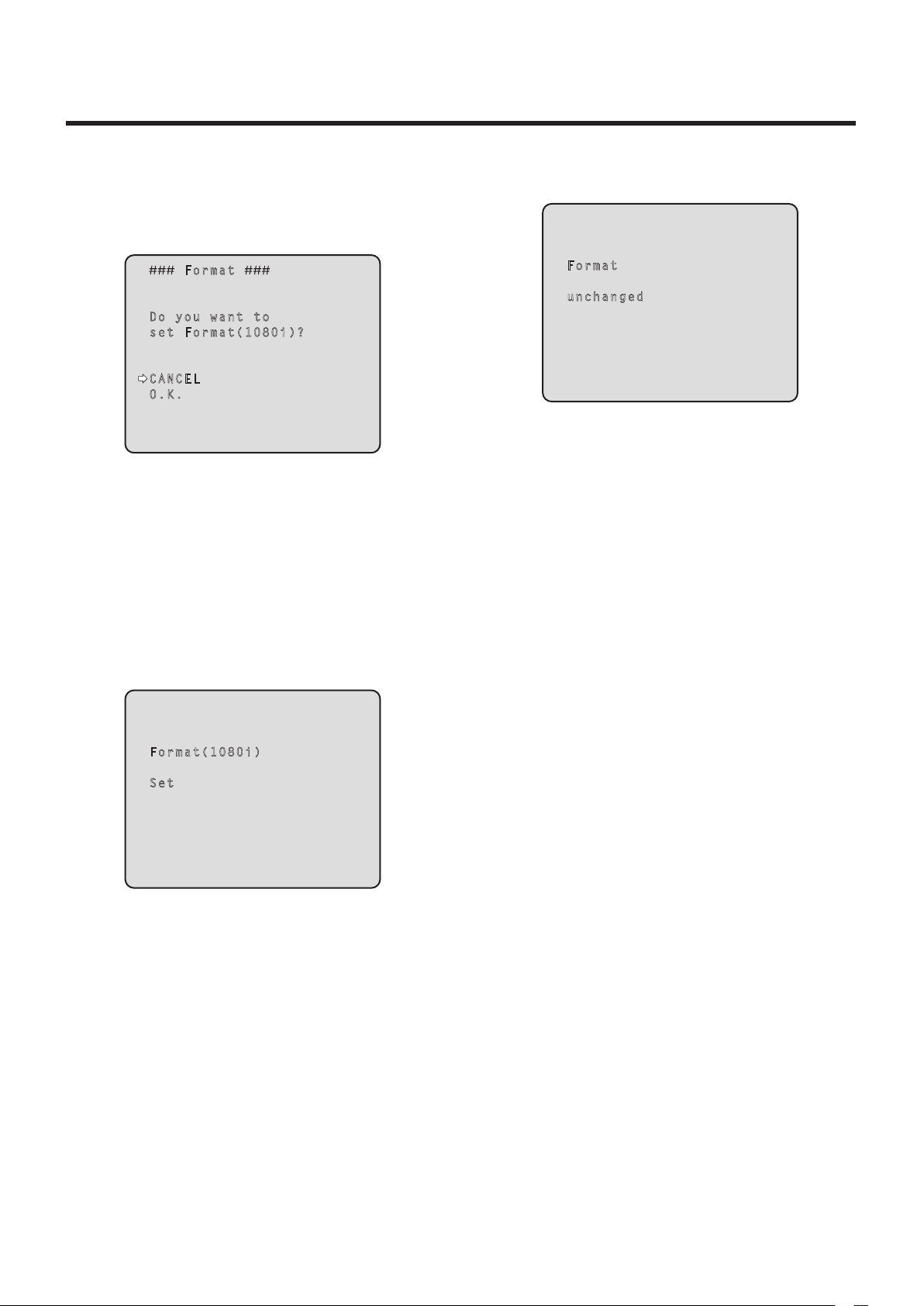
Setting the menu items
Changing the format
When the format is changed on the Output screen from its
current setting, the Format change check screen appears.
Format change check screen
Format unchanged screen
F orm at
Do yo u w ant to
se t F orm at( 108 0 i) ?
CA NCE L
O. K.
The format (1080i, 720p or 480i) to be set is displayed
within the parentheses on the screen.
When the cursor is moved to “O.K.” on the format
change check screen and the setting is entered, the
Format Set screen appears for 5 seconds, and the
format is changed.
After the format has been changed, the display returns
to the Output screen.
Format Set screen
Fo rma t
un cha nge d
Fo r ma t (1 0 80 i )
Se t
The format (1080i, 720p or 480i) to be set is displayed
within the parentheses on the screen.
When the cursor is moved to “CANCEL” on the format
change check screen and the setting is entered, the
Format unchanged screen appears for 5 seconds, the
format is left unchanged, and the display returns to the
Output screen.
45
Page 46

Setting the menu items
Other 1/2 screen
O the r 1 /2
In sta ll Pos iti on De s kt o p
Pr ese t S pee d 1 0
Pr ese t S cop e M o de A
Di git al Zoo m Di s ab l e
Sp eed Wi th Zoo m P O S. O n
Fo cus Mo de Au t o
F ocu s A DJ Wit h P T Z. O n
Re tur n
Install Position [Desktop, Hanging]
“Desktop” or “Hanging” is selected here as the method
used to install the unit.
Desktop: Stand‑alone installation
Hanging: Suspended installation
When “Hanging” has been selected, the top, bottom,
left and right of the images will be reversed, and
up/down/left/right control for panning and tilting will
also be reversed.
Preset Speed [1 to 30]
There are 30 preset pan‑tilt operation speeds of when
regenerating the camera direction and other information
which are registered in the preset memory.
Notes
If a high value is selected for the Preset Speed
setting, the image on the screen may shake when
operation stops.
When connecting the unit to the AW‑RP655 for
use, the “DIAGONAL SPEED (P/T SETTING)”
setting of the AW‑RP655 takes effect.
To change the Preset Speed, change the
AW‑RP655 setting.
Digital Zoom [Disable, Enable]
“Enable” or “Disable” is set here for the digital zoom
function.
If zooming is performed toward the Tele end beyond the
maximum position when “Enable” has been selected, the
digital zoom can be operated continuously. Zooming will
stop temporarily at the position where the optical zoom
and digital zoom are switched so after it has stopped at
this position, proceed with zooming again.
When the setting is changed to “Disable” while already in
the digital zoom region, the zoom will automatically move
to the maximum position of the optical zoom.
Speed With Zoom POS. [Off, On]
“On” or “Off” is set here for the function used to adjust the
camera direction’s adjustment speed in conjunction with
the zoom magnification.
When “On” is set, the panning and tilting operations will
become slower in the zoom status.
This function has no effect during preset operations.
Focus Mode [Auto, Manual]
“Auto” or “Manual” is set here for the focusing function.
Auto: The subjects are always brought into focus
automatically.
Manual: The focus is operated manually.
Focus ADJ With PTZ. [Off, On]
“On” or “Off” is set here for the function which
compensates for out‑of‑focusing when it occurs during
panning, tilting or zooming operations at the manual
focus setting.
When “Off” is set, adjust the focus as required after
zooming or set the focus to the auto mode. This item can
be selected only when “Manual” has been selected as the
“Focus Mode” setting.
Preset Scope [Mode A, Mode B, Mode C]
Selected here are the setting items to be recalled when
the contents of the preset memory are regenerated.
Mode A: Pan, Tilt, Zoom (including digital zoom), Focus,
Iris, Gain, White‑BAL
Mode B: Pan, Tilt, Zoom (including digital zoom), Focus,
Iris
Mode C: Pan, Tilt, Zoom (including digital zoom), Focus
Return
Use this to return to the previous menu.
46
Page 47

Setting the menu items
Other 2/2 screen
O the r 2 / 2
Ta lly En abl e E n ab l e
OS D O ff Wit h T a ll y O f f
OS D S tat us O f f
Wi rel ess Co n tr o l E n ab l e
Re tur n
When menu operations cannot be performed using
other control devices:
1. Turn off the power of the units and devices that are
connected.
2. Disconnect the unit’s power cable, and plug it back
in.
3. Perform the operation for turning on the unit’s
power from the wireless remote control.
4. After changing this item, turn off the unit’s power
and turn it back on.
Tally Enable [Disable, Enable]
“Enable” or “Disable” is set here for the function which
turns on or turns off the tally lamp using the tally control
signal.
OSD Off With Tally [Off, On]
This is used to enable or disable the function for clearing
the OSD menu displays when the tally signal is received
by a command or contact.
When the tally signal is released, the original OSD menu
displays are restored.
OSD Status [Off, On]
“On” or “Off” is set here for the status display which
appears during AWB operations.
Wireless Control [Disable, Enable]
“Enable” or “Disable” is set here for operations conducted
from the wireless remote control.
The operations are enabled when the unit’s power is
turned on from an external device other than a wireless
remote control, and they are disabled when the power is
turned on from a wireless remote control.
Return
Use this to return to the previous menu.
At the point when this item’s setting is changed, the
new setting is not reflected in operation.
It is reflected when the unit is set to the standby mode
and its power is turned on.
Follow one of the procedures below if the item’s setting
is changed by mistake and the unit can no longer be
operated from a wireless remote control.
When menu operations can be performed using
another control device:
First change the item using a control device capable
of performing menu operations, and then turn off the
unit’s power and turn it back on.
47
Page 48

Setting the menu items
Maintenance screen
Ma i nt e na n ce
Fi r mw a re Ve r si o n
In i ti a li z e
Re t ur n
Firmware Version
This is selected to display the Firmware Version screen
on which to check the version of the firmware used.
Initialize
This is selected to display the Initialize screen on which to
initialize the camera’s settings.
For details on operation, refer to “Concerning
initialization” on page 49.
Return
Use this to return to the previous menu.
Firmware Version screen
F irm war e V e rs i on
CP U S oft war e
C ame ra Mai n V 0 1. 0 0
P an/ Til t V 0 1. 0 0
N etw ork V 0 1. 0 0
PL D
C ame ra V 0 1. 0 0
O utp ut V 0 1. 0 0
Re tur n
CPU Software Camera Main
This is selected to display the software version of the
camera unit.
CPU Software Pan/Tilt
This is selected to display the software version of the
pan‑tilt unit.
CPU Software Network
This is selected to display the software version of the
network unit.
PLD Camera
This is selected to display the PLD version of the camera
unit.
PLD Output
This is selected to display the PLD version of the output
unit.
Return
Use this to return to the previous menu.
48
Page 49

Setting the menu items
Concerning initialization
When “Initialize” is selected on the Maintenance screen, the
Initialize screen appears.
Initialize screen
Menu settings unchanged screen
I nit ial ize
Do yo u w ant to in i ti a li z e
Me nu set tin gs?
CA NCE L
O. K.
Re tur n
When the cursor is moved to “O.K.” on the Initialize
screen and the setting is entered, the Menu settings
initialize screen is displayed for 5 seconds, and the
camera settings are restored to the settings which
were established when the camera was purchased.
However, the Format settings (see page 43) and
network settings are not initialized.
When the initialization operation is completed, the
Initialize screen is restored to the display.
Menu settings initialized screen
Me nu set tin g s
un cha nge d
Me nu set tin g s
in iti ali zed
When the cursor is moved to “CANCEL” on the
Initialize screen and the setting is entered, the Menu
settings unchanged screen is displayed for 5 seconds,
the initialization operation is not performed, and the
Initialize screen returns to the display.
49
Page 50

Menu item table
Menu Item
Top Menu Camera Scene Scene FullAuto FullAuto, Manual1, Manual2,
Contrast Contrast Mode ‑‑‑‑ Auto Auto, Manual
Contrast Level 0 0 –5 to +5
Shutter Mode ‑‑‑‑ ‑‑‑‑ Off, Step, Synchro
Step/Synchro
( When “Step” is
selected as the
“Shutter Mode”)
Step/Synchro
( When “Synchro”
is selected as the
“Shutter Mode”)
Frame Mix ‑‑‑‑ ‑‑‑‑ Auto, Off, 6dB, 12dB, 18dB
AutoF.Mix Max Gain ‑‑‑‑ 18dB 0dB, 6dB, 12dB, 18dB
Gain ‑‑‑‑ Auto Auto, 0dB, 3dB, 6dB, 9dB, 12dB,
AGC Max Gain ‑‑‑‑ 18dB 6dB, 12dB, 18dB
Picture Picture 1/2 Chroma Level ‑‑‑‑ 0 –3 to +3
AWB Mode ‑‑‑‑ AWB A ATW, AWB A, AWB B
Detail ‑‑‑‑ High Off, Low, High
Flesh Tone Mode ‑‑‑‑ Off Off, Low, High
Color Matrix ‑‑‑‑ EBU Normal, EBU, NTSC
DNR ‑‑‑‑ High Off, Low, High
Picture 2/2 Pedestal ‑‑‑‑ 0 –10 to +10
DRS ‑‑‑‑ Off Off, Low, High
Gamma Type ‑‑‑‑ Normal Off, Normal, Cinema
Gamma Level ‑‑‑‑ Mid Low, Mid, High
Back Light COMP. ‑‑‑‑ ‑‑‑‑ Off, On
System Genlock
(AW‑HE50S only)
Output Format 1080i 1080i, 720p, 480i
Other Other 1/2 Install Position Desktop Desktop, Hanging
Other 2/2 Tally Enable Enable Disable, Enable
Maintenance Firmware Version CPU Software
Initialize ‑‑‑‑ CANCEL CANCEL, OK
Horizontal Phase 0 –206 to +49
Subcarrier Phase
Coarse 90° 0° to 315°
Fine 0 –127 to +127
H Phase.SC Fine Step 1 1 to 10
Down CONV. Mode Squeeze Squeeze, SideCut, LetterBox
HDMI Color
(AW‑HE50H only)
Preset Speed 10 1 to 30
Preset Scope Mode A Mode A, Mode B, Mode C
Digital Zoom Disable Disable, Enable
Speed With Zoom POS. On Off, On
Focus Mode Auto Auto, Manual
Focus ADJ With PTZ. ‑‑‑‑ Off, On
OSD Off With Tally Off Off, On
OSD Status Off Off, On
Wireless Control Enable Disable, Enable
Camera Main Version shipped ‑‑‑‑
Pan/Tilt Version shipped ‑‑‑‑
Network Version shipped ‑‑‑‑
PLD
Camera Version shipped ‑‑‑‑
Output Version shipped ‑‑‑‑
Factory setting
FullAuto
‑‑‑‑ ‑‑‑‑ 1/100, 1/250, 1/500, 1/1000,
‑‑‑‑ ‑‑‑‑ 60.24Hz to 646.21Hz
YCbCr422 RGB‑NOR, RGB‑ENH,
Manual1 to 3
Selection items
Manual3
1/2000, 1/4000, 1/10000
(1 to 255 steps)
15dB, 18dB
YCbCr422, YCbCr444
50
Page 51

Web setting screen
Connect the unit and a personal computer, and establishing
the settings on the Web browser screen.
The LAN crossover cable is used when connecting a
personal computer directly to the unit’s LAN connector for IP
control, and the LAN straight cable is used when making the
connection through a switching hub.
Select an IP address for the personal computer within the
private address range while ensuring that it is different from
the address of the unit.
Set the subnet mask to the same address as the unit.
Note
If you need to change the IP address and subnet
mask, be sure to ask your dealer to make these
changes for you.
Unit’s IP address and subnet mask (factory settings)
IP address: 192.168.0.10
Subnet mask: 255.255.255.0
For details of the required personal computer
environment, refer to page 4.
51
Page 52

Web setting screen
Menu operations
Start the Web browser, and enter “http://192.168.0.10/” in the [Address] box of the Web browser.
When the IP address has been changed, the URL will also change.
If this is the case, set the changed IP address to the URL (http://changed IP address/).
The menus can be switched by selecting the buttons on the left side of the screen.
<Control> <Setup>
52
Page 53

Web setting screen
Control button / Setup button
Press the Control button to switch to the Control screen
on which to control such operations as the panning,
tilting, zooming and focusing of the camera. (See
page 54)
Press the Setup button to switch to the Image Adjust
screen on which to establish the camera’s settings.
(See page 56)
When the Setup button is pressed, the login screen
shown below is displayed.
When logging in for the first time, input the following
default values.
User name admin
Password 12345
Power ON button / Standby button
The unit’s power is turned on when the Power ON button
is pressed.
When the Standby button is pressed, the unit is set to the
standby mode.
While the standby mode is established, the control over
the camera’s operations exercised on the Control screen
and both the Image button and Maintenance button on
the Setup screen are disabled.
Notes
If Power ON or Standby is selected too quickly,
the status selected and the display shown may not
correspond.
In a case like this, press the F5 key to restore the
correct status display.
When operation is transferred to the standby
mode: The current pan‑tilt position is stored in
the memory (as a POWER ON preset), and the
panning/tilting moves so that the camera points in
the backward‑facing direction.
When operation is transferred to the POWER ON
mode: Panning/tilting moves to the position which
was stored in the memory (as a POWER ON
preset) when operation was transferred to the
standby mode.
When the OK button is clicked after inputting the values,
the screen shown below is displayed.
Click the OK button.
Note
On the User auth. screen (see page 66), register
the user name and password of your choice at the
earliest possible opportunity.
53
Page 54

Web setting screen
Control screen
This is the screen on which such operations as the panning, tilting, zooming and focusing of the unit can be controlled.
Zoom
Use this to adjust the zoom (magnification)
in the Wide direction.
Use this to adjust the zoom (magnification)
to 1.0.
Use this to adjust the zoom (magnification)
in the Tele direction.
Focus
Use this to adjust the focus
manually.
Use this to adjust the focus in
the Near direction.
It does not work during
automatic adjustments.
Use this to adjust the focus in
the Far direction.
It does not work during
automatic adjustments.
When this is pressed while
the focus is being adjusted
manually, the focus will
be temporarily adjusted
automatically.
It does not work during
automatic adjustments.
Use this to adjust the focus
automatically.
54
Page 55

Web setting screen
Control pad and its buttons
To adjust the image in the horizontal
or vertical direction (panning or
tilting), left‑click the pad and the
buttons.
The more the outside of the pad
is clicked, the faster the camera
operates. Adjustment is also possible
by dragging the mouse.
Right‑click the pad to initiate
zooming and focusing.
When the top half of the pad is
clicked in the up or down direction,
the zoom (magnification) is adjusted
in the Tele direction; conversely,
when the bottom half of the pad is
adjusted, the zoom is adjusted in the
Wide direction.
When the left half of the pad is
clicked in the left or right direction,
the focus is adjusted in the Near
direction; conversely when the right
half of the pad is adjusted, the focus
is adjusted in the Far direction.
The zooming can also be adjusted
by operating the mouse wheel.
Note
When the mouse is used for dragging and
dropping from the control pad area to a position
outside this area, the panning, tilting and other
operations will not stop.
In a case like this, click the control pad area to
stop these operations.
Preset
When the preset position is selected from
the pull‑down menu and the Move button is
clicked, the camera direction moves to the
preset position which was registered ahead
of time.
This is used to register the current status
in the preset position now selected on the
pull‑down menu.
It does not function if “Home” has been
selected on the pull‑down menu.
The camera direction moves to the preset
position which is now selected on the
pull‑down menu.
The settings that are reproduced at this
position are the settings which were
established on the “Preset Scope” menu
(see page 65).
The camera direction moves to the home
position if “Home” has been selected on the
pull‑down menu.
Brightness
Use this to adjust the image brightness
manually.
Use this to make the image darker.
It does not work during automatic
adjustments.
Use this to make the image lighter.
It does not work during automatic
adjustments.
Use this to adjust the image brightness
automatically.
55
Page 56

Web setting screen
Setup screen
Pressing the Setup button switches the display to this screen on which the unit’s settings are established.
Basic screen
Basic button
When the Basic button is pressed, the Basic screen is
displayed in the area on the right.
Camera title [0 to 20 half‑size characters]
<Initial setting: AW‑HE50>
Input the name of the camera here.
When the Set button is clicked, the input name appears in
the status display area.
56
Page 57

Web setting screen
Image screen
Image
Image
Image adjust
This is used to display the Image Adjust screen.
Preset position
This is used to display the Preset Position setting screen.
57
Page 58

Web setting screen
Image adjust screen
When Scene is set to “FullAuto” When Scene is set to “Manual1 to 3”
58
Page 59

Web setting screen
Scene
[FullAuto, Manual1, Manual2, Manual3]
Selected here is the shooting mode that matches the
shooting situation.
Select the mode which best suits the prevailing shooting
conditions and the user’s preferences.
FullAuto In this mode, the optimum settings and
adjustments for the shooting conditions
at hand are automatically established.
When “FullAuto” has been selected, the
detailed setting and adjustment menus
are not displayed.
Manual1 to 3 In these modes, the detailed settings and
adjustments are established manually to
match the prevailing shooting conditions
and the user’s preferences.
When the Manual1, Manual2 or Manual3
mode has been selected, the detailed
setting and adjustment menu for the
mode concerned is displayed.
Contrast
Contrast Mode [Auto, Manual]
This item is used to select whether the image brightness
(contrast) is to be controlled automatically or manually.
Auto The iris, shutter speed and frame addition
are controlled and the camera brightness is
adjusted automatically.
Manual Operations are performed using the manually
set values.
The shutter speeds that can be set are listed below.
When “Step” is selected as
the “Shutter Mode”
1/100, 1/250, 1/500, 1/1000,
1/2000, 1/4000, 1/10000
When “Synchro” is selected
as the “Shutter Mode”
60.24 Hz to max. 646.21 Hz
(255 steps)
Frame Mix [Auto, Off, 6dB, 12dB, 18dB]
Select for frame addition (gain‑up using sensor storage)
amount.
This item can be set when “Off” is selected as the
“Shutter Mode” item setting.
When frame addition is performed, it will appear as if the
images are missing some frames.
AutoF. Mix Max Gain
[0dB, 6dB, 12dB, 18dB]
When “Auto” for the “Contrast Mode” or “Auto” for the
“Frame Mix” is selected, the maximum frame addition
amount can be set.
If frame addition is performed at the Auto setting, it will
appear as if the images are missing some frames.
Gain [ Auto, 0dB, 3dB, 6dB, 9dB, 12dB, 15dB,
18dB]
The image gain is adjusted here.
In locations which are too dark, adjust the gain upward;
conversely, in locations which are too bright, adjust it
downward.
When “Auto” is set, the light quantity is adjusted
automatically.
The noise increases when the gain is increased.
AGC Max Gain [6dB, 12dB, 18dB]
When “Auto” is selected as the “Gain” setting, the
maximum gain‑up amount can be set.
Contrast Level [–5 to +5]
Set here is the contrast level when the image brightness
is adjusted.
This item can be set when “Auto” has been selected as
the “Contrast Mode” setting.
Shutter Mode [Off, Step, Synchro]
Select for camera shutter speed.
This item can be set when “Manual” has been selected as
the “Contrast Mode” setting.
When a higher shutter speed is selected, fast‑moving
subjects do not become blurred easily but the images will
be darker.
Off The shutter is set to OFF (so that it cannot be
tripped).
Step The step shutter is set (the steps can be
changed).
Synchro The synchro shutter is set (the setting can be
changed continuously).
59
Page 60

Web setting screen
Picture
Chroma Level [–3 to +3]
Set here is the color intensity (chroma level) of the
images.
AWB
This is used to execute automatic white balance (AWB) to
set the white balance.
For details, refer to page 22.
AWB Mode [ATW, AWB A, AWB B]
The white balance mode is selected here.
Select the mode when the coloring is not natural because
of the nature of the light source or other factors.
If the white color serving as the reference can be
recognized, subjects can be shot with natural coloring.
ATW In this mode, the white balance is
compensated for automatically, even if
changes occur in the light source or color
temperature, by a process of continuous and
automatic adjustment.
AWB A,
AWB B
When AWB A or AWB B is selected and the
white balance is executed, the adjustment
results obtained are stored in the memory
selected.
When AWB A or AWB B is then selected, the
white balance stored in the selected memory
can be recalled.
Note
When preset settings have been called from the
AW‑RP655, the AWB mode which was set when
the preset data was registered by the AW‑RP655
will be called.
Detail [Off, Low, High]
The image detail (image sharpness) is adjusted here.
When “Low” or “High” is selected, the detail is enhanced.
Flesh Tone Mode [Off, Low, High]
Set here is the flesh tone mode for displaying the
subjects’ skin so that it appears more smoothly and
eye‑pleasingly.
When “Low” or “High” is selected, the effect is enhanced
even more.
Color Matrix [Normal, EBU, NTSC]
This item is used to load the preset color matrix data and
compensate for the saturation and color phase.
DNR [Off, Low, High]
Set here is the level of the digital noise reduction effect so
that light, noise‑free and clear images will be output even
at night and in other low‑brightness environments.
When “Low” or “High” is selected, even more noise can
be eliminated.
However, there is an increased possibility that
afterimages may occur.
Pedestal [–10 to +10]
This item is used to adjust the black level (adjust the
pedestal) so that the dark parts of the images are easier
to see.
These parts become darker when a negative setting is
selected and, conversely, lighter when a positive setting
is selected.
DRS [Off, Low, High]
Set here is the DRS function which provides just the right
amount of compensation when images with significant
light/dark differences are displayed.
When “Low” or “High” is selected, the effect is enhanced
even more.
This may make noise more perceptible with some scenes.
Gamma Type [Off, Normal, Cinema]
Selected here is the type of gamma curve.
The selected setting takes effect when “Off” is selected
as the “DRS” item setting. Normally, the “Normal” setting
is used. When “Cinema” is selected, images giving off an
atmosphere like movies can be shot.
Gamma Level [Low, Mid, High]
This item is used to adjust the gamma compensation
level. The selected setting takes effect when “Off” is
selected as the “DRS” item setting or when “Normal” is
selected as the “Gamma Type” setting.
When “Low” is set, the images appear sedate and
composed. The resulting gamma curve has a gentle
gradient in the low‑brightness areas, and the contrast is
sharper.
Conversely, when “High” is set, the tonal range in the dark
area is expanded so that the images take on a lighter
tone. The resulting gamma curve has a sharp gradient in
the low‑brightness areas, and the contrast is softer.
Back Light COMP. [Off, On]
“On” or “Off” is set here for the backlight compensation
function.
Under backlight conditions, the function prevents
darkening as a result of light striking the backs of
subjects, and makes it possible to shoot images in shade
or shadow more brightly.
This item can be set when “Auto” has been selected as
the “Contrast Mode” setting.
The function takes effect when “Auto” has been selected
as the Contrast Mode, Gain or Frame Mix item setting.
60
This is used to close this panel.
Page 61
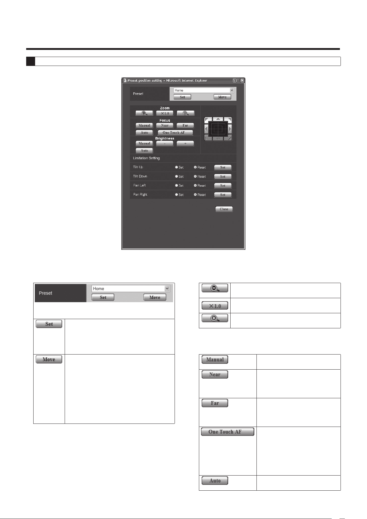
Web setting screen
Preset position setting screen
Preset
This selects the preset position to be
operated from the pull‑down menu.
This is used to register the current status
in the preset position now selected on the
pull‑down menu.
It does not function if “Home” has been
selected on the pull‑down menu.
The camera direction moves to the preset
position which is now selected on the
pull‑down menu.
The settings that are reproduced at this
position are the settings which were
established on the “Preset Scope” menu
(see page 65).
The camera direction moves to the home
position if “Home” has been selected on the
pull‑down menu.
Zoom
Use this to adjust the zoom (magnification)
in the Wide direction.
Use this to adjust the zoom (magnification)
to 1.0.
Use this to adjust the zoom (magnification)
in the Tele direction.
Focus
Use this to adjust the focus
manually.
Use this to adjust the focus in
the Near direction.
It does not work during
automatic adjustments.
Use this to adjust the focus in
the Far direction.
It does not work during
automatic adjustments.
When this is pressed while
the focus is being adjusted
manually, the focus will
be temporarily adjusted
automatically.
It does not work during
automatic adjustments.
Use this to adjust the focus
automatically.
61
Page 62

Web setting screen
Brightness
Use this to adjust the image brightness
manually.
Use this to make the image darker.
It does not work during automatic
adjustments.
Use this to make the image lighter.
It does not work during automatic
adjustments.
Use this to adjust the image brightness
automatically.
Control pad and its buttons
To adjust the image in the horizontal
or vertical direction (panning or
tilting), left‑click the pad and the
buttons.
The more the outside of the pad
is clicked, the faster the camera
operates. Adjustment is also possible
by dragging the mouse.
Right‑click the pad to initiate
zooming and focusing.
When the top half of the pad is
clicked in the up or down direction,
the zoom (magnification) is adjusted
in the Tele direction; conversely,
when the bottom half of the pad is
adjusted, the zoom is adjusted in the
Wide direction.
When the left half of the pad is
clicked in the left or right direction,
the focus is adjusted in the Near
direction; conversely when the right
half of the pad is adjusted, the focus
is adjusted in the Far direction.
The zooming can also be adjusted
by operating the mouse wheel.
Limitation Setting
This establishes the up, down, left and right limit settings
of the pan‑tilt head.
First, move the pan‑tilt head to the position where the
limit is to be set, and press the corresponding button
below to set the direction (up, down, left or right) in which
the limit is to be set.
After each setting has been selected, press the Set
button to enter the setting.
Tilt Up
Tilt Down
Pan Left
Pan Right
Set/Reset
Use this to save the current position as
the upward limit.
Use this to save the current position as
the downward limit.
Use this to save the current position as
the leftward limit.
Use this to save the current position as
the rightward limit.
Use this to enable or disable the limit
setting in each direction.
This is used to close this panel.
Note
When the mouse is used for dragging and
dropping from the control pad area to a position
outside this area, the panning, tilting and other
operations will not stop.
In a case like this, click the control pad area to
stop these operations.
62
Page 63

Web setting screen
System
This menu has items that relate to the genlock phase adjustment and camera’s output image settings.
Genlock (AW‑HE50S only)
This item’s setting is reflected immediately.
Horizontal Phase [–206 to +49]
This is used to adjust the horizontal phase during
genlock.
Subcarrier Phase Coarse
[0° to 315°]
This is used to adjust coarsely the color phase during
genlock.
This setting is valid for the VBS signal output.
Subcarrier Phase Fine [–127 to +127]
This is used to adjust finely the color phase during
genlock.
This setting is valid for the VBS signal output.
63
Page 64

Web setting screen
Output
This item’s setting is reflected when the Set button is
pressed.
Format [1080i, 720p, 480i]
The video format is changed on this screen.
Down CONV. Mode
[Squeeze, SideCut, LetterBox]
The down‑conversion mode is selected here.
When the 4:3 aspect ratio has been set
for the monitor screen, the images are
squeezed horizontally and extended
Squeeze
SideCut
vertically changing the view of the angle.
With the vertical height serving as the
reference, the parts which extend beyond
this at the two sides are cropped changing
the view of the angle.
HDMI Color (AW‑HE50H only)
[RGB‑NOR, RGB‑ENH, YCbCr422, YCbCr444]
Set here is the HDMI color output.
When an HDMI monitor is used, use “YCbCr422”
under normal circumstances.
In cases where, for instance, HDMI (RGB) signals are
converted and output to a DVI monitor, the settings
required will differ depending on the color gradation
supported by the monitor.
RGB‑NOR The RGB output signals are output in
the 16 to 235 range.
RGB‑ENH The RGB output signals are output in
the 0 to 255 range.
If the black parts of the images appear overexposed
when “RGB‑NOR” has been selected, use the “RGB‑
ENH” setting instead.
Conversely, if the images are displayed with a loss of
dark detail when “RGB‑ENH” has been selected, use
the “RGB‑NOR” setting instead.
Note
If an HDMI Color setting which is not supported by
the monitor has been specified, the HDMI Color
setting may be changed automatically.
(The menu display will remain unchanged.)
With the horizontal width serving as the
reference, black bands are added at the top
and bottom changing the view of the angle.
LetterBox
When output is selected for the color bar, the mode is
fixed to Squeeze.
If “SideCut” or “LetterBox” has been selected, the HDMI
output will not appear for a few seconds when the color
bar display is set to ON or OFF.
With the AW‑HE50S, this item cannot be selected.
64
Page 65

Web setting screen
Other
This item’s setting is reflected when the Set button is
pressed.
Install Position [Desktop, Hanging]
“Desktop” or “Hanging” is selected here as the method
used to install the unit.
Desktop Stand‑alone installation
Hanging Suspended installation
When “Hanging” has been selected, the top, bottom,
left and right of the images will be reversed, and
up/down/left/right control for panning and tilting will
also be reversed.
Preset Speed [1 to 30]
There are 30 preset pan‑tilt operation speeds of when
regenerating the camera direction and other information
which are registered in the preset memory.
Notes
If a high value is selected for the Preset Speed
setting, the image on the screen may shake when
operation stops.
When connecting the unit to the AW‑RP655 for
use, the “DIAGONAL SPEED (P/T SETTING)”
setting of the AW‑RP655 takes effect.
To change the Preset Speed, change the
AW‑RP655 setting.
Preset Scope [Mode A, Mode B, Mode C]
Selected here are the setting items to be recalled when
the contents of the preset memory are regenerated.
Mode A Pan, Tilt, Zoom (including digital zoom),
Focus, Iris, Gain, White‑BAL
Mode B Pan, Tilt, Zoom (including digital zoom),
Focus, Iris
Mode C Pan, Tilt, Zoom (including digital zoom),
Focus
Digital Zoom [Disable, Enable]
“Enable” or “Disable” is set here for the digital zoom
function.
If zooming is performed toward the Tele end beyond the
maximum position when “Enable” has been selected, the
digital zoom can be operated continuously. Zooming will
stop temporarily at the position where the optical zoom
and digital zoom are switched so after it has stopped at
this position, proceed with zooming again.
When the setting is changed to “Disable” while already in
the digital zoom region, the zoom will automatically move
to the maximum position of the optical zoom.
Speed With Zoom POS. [Off, On]
“On” or “Off” is set here for the function used to adjust the
camera direction’s adjustment speed in conjunction with
the zoom magnification.
When “On” is set, the panning and tilting operations will
become slower in the zoom status.
This function has no effect during preset operations.
Focus Mode [Auto, Manual]
“Auto” or “Manual” is set here for the focusing function.
Auto The subjects are always brought into focus
automatically.
Manual The focus is operated manually.
Focus ADJ With PTZ. [Off, On]
“On” or “Off” is set here for the function which
compensates for out‑of‑focusing when it occurs during
panning, tilting or zooming operations at the manual
focus setting.
When “Off” is set, adjust the focus as required after
zooming or set the focus to the auto mode. This item can
be selected only when “Manual” has been selected as the
“Focus Mode” setting.
Tally Enable [Disable, Enable]
“Enable” or “Disable” is set here for the function which
turns on or turns off the tally lamp using the tally control
signal.
OSD Status [Off, On]
“On” or “Off” is set here for the status display which
appears during AWB operations.
65
Page 66

Web setting screen
User mng.
The authorization of those users who can access the camera from a PC or AW‑RP50 and those IP addresses, from which the
camera can be accessed, is registered on this screen in order to restrict any other access.
The screen itself consists of two tabs, “User auth.” and “Host auth”.
User auth. screen
User auth.
<Initial setting: Off>
User authorization is set to “On” or “Off” here.
Enter the setting using the Set button.
User name [1 to 32 half‑size characters]
<Initial setting: blank>
The user name is input here.
Enter the setting using the Set button.
Password
Retype password [4 to 32 half‑size characters]
<Initial setting: blank>
The password is input here.
Enter the setting using the Set button.
Access level
<Initial setting: 2. Camera control>
Select one of the following settings as the user access
level.
Enter the setting using the Set button.
1. Administrator This access level allows the user to
perform all the unit’s operations.
2. Camera control This access level allows only
Control screen operations to be
performed.
User check
A pull‑down menu can be opened here, and the
registered users checked.
A registered user is indicated in the form of “Registered
user name [Access level]”.
(Example: admin[1])
To delete a registered user, select the user to be deleted,
and click the Delete button on the right.
66
Page 67

Web setting screen
Host auth. screen
Host auth.
<Initial setting: Off>
Host authorization is set to “On” or “Off” here.
IP address
<Initial setting: blank>
The IP address of the PC from which access to the
camera is allowed is input here.
The host name cannot be input as the IP address.
When the “IP address/subnet mask length” is input,
the PCs which are allowed to access the camera can
be restricted on a subnet by subnet basis.
If, for instance, “192.168.0.1/24” has been input and
the “2. Camera control” setting has been selected as
the access level setting, the PCs from “192.168.0.0” to
“192.168.0.255” will be able to access the camera at
the “2. Camera control” access level.
When an already registered IP address is input and
the Set button is clicked, the host information will be
overwritten.
Access level
<Initial setting: 2. Camera control>
Select one of the following settings as the host access
level.
1. Administrator
2. Camera control
For details on the access level, refer to page 66.
Host check
A pull‑down menu can be opened here, and the IP
addresses of the registered hosts checked.
A host is indicated in the form of “Registered IP address
[Access level]”.
(Example: 192.168.0.21 [1])
To delete a registered host (IP address), select the host
to be deleted, and click the Delete button on the right.
67
Page 68

Web setting screen
Server
This screen has items that relate to the NTP server addresses, port numbers and other NTP server settings.
NTP screen
Time adjustment
<Initial setting: Off>
Select one of the following settings as the time
adjustment method.
The time is adjusted by the method selected here and
used as the unit’s standard time.
Off The time is counted from 0:00 on
January 1, 1990 as the unit’s startup
time.
Synchronization
with NTP server
The time automatically adjusted in
synchronization with the NTP server
is used as the unit’s standard time.
NTP server address
[1 to 63 half‑size characters]
<Initial setting: blank>
The host name or IP address of the NTP server is input
here.
Note
To input the “NTP server address” host name, the
DNS setting must be selected on the Network
screen (see page 70) of the Network settings.
NTP port [1 to 65535]
<Initial setting: 123>
The port number of the NTP server is input here.
Time adjustment interval
<Initial setting: 1h>
The interval (1 to 24 hours in 1‑hour increments) for
acquiring the time from the NTP server and updating the
time is selected here.
Time zone
<Initial setting: (GMT ‑08:00) Pacific Time (US &
Canada), Tijuana>
Select the time zone that corresponds with the region in
which the unit is going to be used.
68
Page 69

Web setting screen
Network
This screen has items that relate to the network settings, DDNS (Dynamic DNS) and SNMP (Simple Network Management
Protocol).
It consists of the three tabs of “Network”, “DDNS” and “SNMP”.
Network screen
IP network
DHCP
<Initial setting: Off>
Whether the DHCP function is to be used is set by
selecting “On” or “Off” here. Set the DHCP server in such
a way that the same IP address cannot be used by PCs
without the DHCP function or by other network cameras.
For details on the server settings, consult your network
administrator.
IP address
<Initial setting: 192.168.0.10>
Input the unit’s IP address here when the DHCP function
is not going to be used. Input an address that will not
duplicate an existing IP address which has been set for a
PC or another network camera.
Multiple IP addresses cannot be used even when the
DHCP function is used.
For details on the DHCP server settings, consult your
network administrator.
69
Page 70

Web setting screen
Subnet mask
<Initial setting: 255.255.255.0>
Input the unit’s subnet mask here if the DHCP function is
not going to be used.
Default gateway
<Initial setting: 192.168.0.1>
Input the unit’s default gateway if the DHCP function is
not going to be used.
Multiple IP addresses cannot be used for the default
gateway even when the DHCP function is used.
For details on the DHCP server settings, consult your
network administrator.
DNS
<Initial setting: Manual>
Whether the DNS server address is to be acquired
automatically (Auto) or manually (Manual) is input here.
If “Manual” has been selected, the DNS settings must be
established.
If “Auto” is selected when the DHCP function is going
to be used, the DNS server address is acquired
automatically.
For further details, consult your system administrator.
Primary server address
Secondary server address
<Initial setting: blank>
Input the IP address of the DNS server if the “Manual”
setting has been selected for “DNS”.
For details on the IP address of the DNS server, consult
your system administrator.
HTTP port [1 to 65535]
<Initial setting: 80>
The port number is allocated here separately.
The following port numbers are used by the unit therefore
cannot be used.
Port numbers already used
20, 21, 23, 25, 42, 53, 67, 68, 69,
110, 123, 161, 162, 554, 995, 10669, 10670,
59000 to 59999, 60000 to 61000
Line speed
<Initial setting: Auto>
Select one of the following data line speeds.
Normally, it is recommended that the “Auto” default
setting be used.
Auto The line speed is set automatically.
100 M‑Full The line speed is set to 100 Mbps full
duplex.
100 M‑Half The line speed is set to 100 Mbps half
duplex.
10 M‑Full The line speed is set to 10 Mbps full duplex.
10 M‑Half The line speed is set to 10 Mbps half duplex.
FTP access to camera
<Initial setting: Forbid>
Whether FTP access to the camera is to be allowed is set
by selecting “Allow” or “Forbid”.
Bandwidth control(bit rate)
<Initial setting: Unlimited>
Select one of the following data bandwidth settings.
Unlimited 384 kbps 2048 kbps
64 kbps 512 kbps 4096 kbps
128 kbps 768 kbps 8192 kbps
256 kbps 1024 kbps
Easy IP Setup accommodate period
<Initial setting: Unlimited>
Select “20min” or “Unlimited” as the time for enabling the
operation of the network settings from the Easy IP Setup
Software.
20min The setting operations from the Easy IP
Setup Software are enabled for 20 minutes
after the camera has started operating.
Unlimited The setting operations from the Easy IP
Setup Software are enabled at all times.
70
Page 71
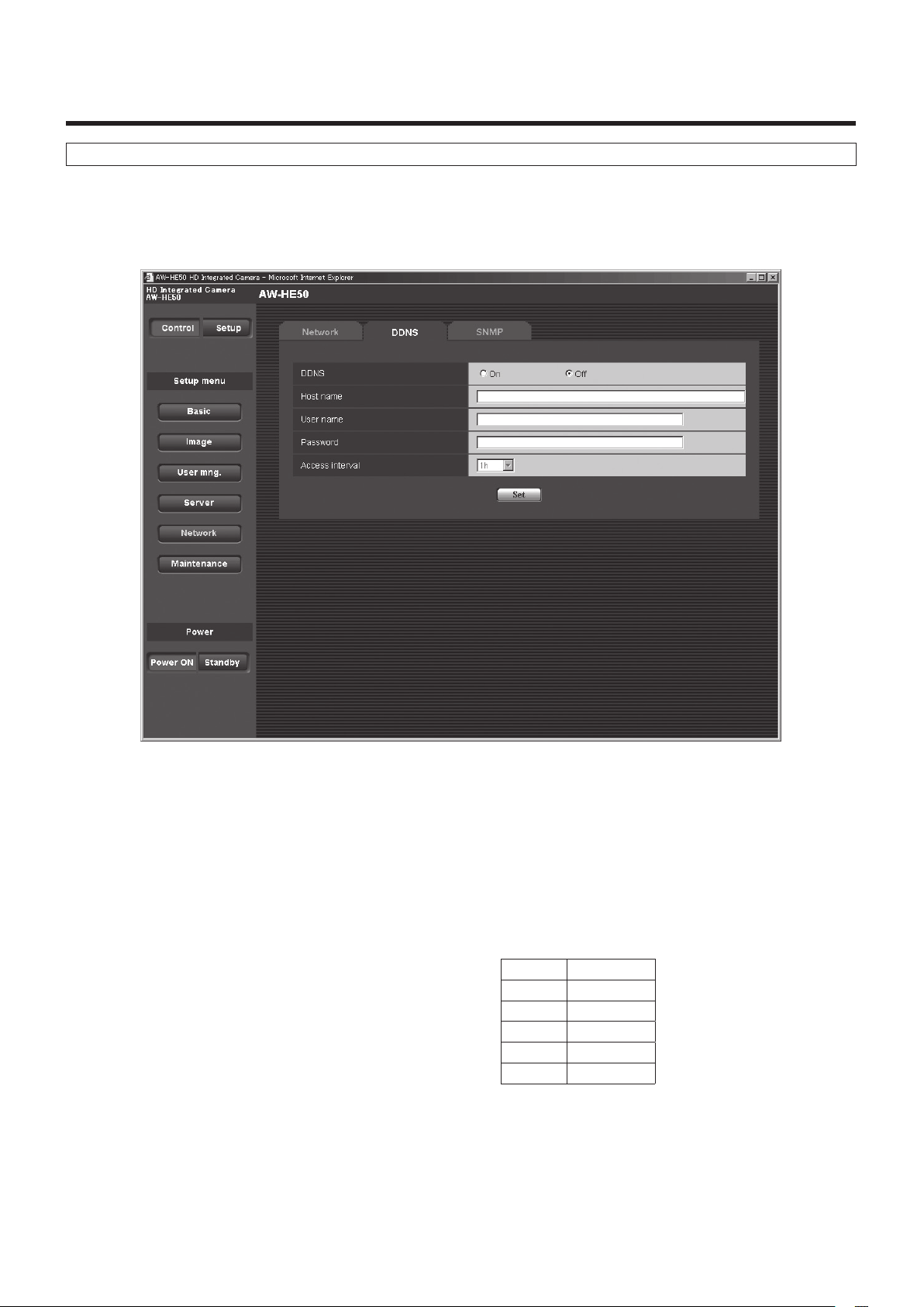
Web setting screen
DDNS screen
Use DHCP to acquire the global IP address.
The DDNS function must be set in order to access the unit over the Internet.
When using the DDNS function, access the unit using the “address of host name.nmdns.net” which was registered in the DDNS
server. To use the DDNS function, a connection with a dedicated DDNS server is required.
DDNS
<Initial setting: Off>
Whether the DDNS function is to be used is selected by
setting “On” or “Off”.
Host name [1 to 64 half‑size characters]
<Initial setting: blank>
Input here the host name to be used.
User name [1 to 32 half‑size characters]
<Initial setting: blank>
Input here the user name (log‑in name) for accessing the
DDNS server.
Password [0 to 32 half‑size characters]
<Initial setting: blank>
Input here the password for accessing the DDNS server.
Access interval
<Initial setting: 1h>
Select one of the settings below to be used as the access
interval in which the IP address and host name are
checked with the DDNS server.
1min 1 minute
10min 10 minutes
30min 30 minutes
1h 1 hour
6h 6 hours
24h 24 hours
71
Page 72

Web setting screen
SNMP screen
The settings related to the SNMP function are selected on this screen.
When the SNMP manager is used for the connection, the unit’s statuses can be checked.
When the SNMP function is to be used, consult with your network administrator.
Community [0 to 32 half‑size characters]
<Initial setting: blank>
Input here the community name which is to be monitored.
Note
When using the SNMP function, be absolutely sure
to input the community name.
This function cannot be used if the community
name field is left blank.
System name [0 to 32 half‑size characters]
<Initial setting: blank>
Input here the system name for controlling the unit using
the SNMP function.
Location [0 to 32 half‑size characters]
<Initial setting: blank>
Input here the location where the unit has been installed.
Contact [0 to 255 half‑size characters]
<Initial setting: blank>
Input here the email address or telephone number of the
administrator.
72
Page 73

Web setting screen
Maintenance
Among the various maintenance operations performed on this screen are system log checks, system version upgrading and
initialization of the unit.
The screen itself consists of five tabs: “System log”, “Upgrade”, “Default reset”, “Back up” and “Other”.
System log screen
A maximum of a hundred system logs can be stored in the unit’s internal memory.
When this maximum number has been exceeded, the old logs are overwritten successively by the new logs.
The logs are cleared when the unit’s power is turned off.
No
The running numbers of the system logs are displayed
here.
Time & date
The times and dates when the logs were generated are
displayed here.
The 24‑hour system is used to display this information.
Error description
Details of the error logs are displayed here.
For further details on the system logs, refer to page 79.
73
Page 74

Web setting screen
Upgrade screen
On this screen, it is possible to check the unit’s software versions and upgrade them to the latest versions.
For details on the software used for version upgrading, consult your dealer.
The “Model no.”, “MAC address”, “Serial no.”, “Firmware version” and other information about the unit is displayed.
1 After consulting with your dealer, download
the latest software to the hard disk of your
personal computer.
Note
No spaces or full‑size characters can be used for
the directory in which the software will be stored.
2 Select the software to be upgraded by clicking
the [Camera Main] or [Network] radio button.
3 Click the Browse button, and specify the
downloaded software.
4 Click the radio button underneath, and after
the software version has been upgraded,
select whether to initialize the data.
Judge whether or not to initialize the data after
reading through the Readme file which accompanies
the software.
5 Click the Execute button.
The software version is upgraded, and the screen on
which to check data initialization is displayed.
If the data is not going to be initialized after the version
has been upgraded, the check screen is not displayed.
After upgrading the software version, be absolutely sure
to delete the temporary Internet files.
74
Page 75
Web setting screen
Notes
Use the personal computer on the same subnet as
the camera to upgrade the software version.
Before using the version upgrading software, be
absolutely sure to check the precautions to be
observed with your dealer, and follow the dealer’s
instructions.
Use the following files specified by Panasonic
System Networks Co., Ltd. as the software used
for version upgrading.
Camera Main bin files
Network img files
Be absolutely sure to write the filenames as below
(see *) for the files of the software used for version
upgrading.
Camera Main he50_cameramain_xxxxx.bin*
Network he50_network_xxxxx.img*
*: Enter the software version in the “xxxxx” part.
Do not turn off the unit’s power while a software
version is being upgraded.
While a software version is being upgraded, do not
attempt to execute any other operations until the
version has been upgraded.
Even when “Reset the settings to the defaults
after completing the upgrade” has been selected,
the network‑related data listed below will not be
initialized.
· DHCP On/Off
· IP address
· Subnet mask
· Default gateway
· HTTP port
· Line speed
· Bandwidth control (bit rate)
75
Page 76

Web setting screen
Default reset screen
The unit’s setting data and HTML files are initialized and the unit is restarted on this screen.
Reset to the default
(Except the network settings)
When the Execute button is clicked, the unit’s settings are
returned to their defaults.
However, the network‑related settings are not initialized.
(See page 75)
When the initialization operation is started, no operations
can be undertaken for about 2 minutes.
Load the default HTML files (setup menu)
When the Execute button is clicked, the HTML files are
returned to their defaults.
When the initialization operation is started, no operations
can be undertaken for about 2 minutes.
Reset to the default and load the default HTML
files
When the Execute button is clicked, the unit’s settings
and HTML files are returned to their defaults.
However, the network‑related settings are not initialized.
(See page 75)
When the initialization operation is started, no operations
can be undertaken for about 2 minutes.
Reboot
When the Execute button is clicked, the unit is rebooted.
After the unit has been rebooted, no operations can be
undertaken for about 2 minutes as is the case when the
unit’s power is turned on.
76
Page 77

Web setting screen
Back up screen
On this screen, the unit’s settings can be saved to a personal computer or settings saved in a personal computer can be loaded
into the unit for use.
Download
The unit’s settings are saved in the personal computer.
After displaying the save destination dialog box using the
Execute button, specify the save destination folder.
Listed below are the settings to be saved.
• Scene FullAuto settings
• Scene Manual1 settings
• Scene Manual2 settings
• Scene Manual3 settings
• System settings
• Preset settings
Upload
The unit’s setting files, which were saved in the personal
computer by the download function, are uploaded.
Click the Browse button to display the dialog box, and
specify the saved file.
Notes
Use the files downloaded by the unit as the data to
be used for uploading.
Do not change the extension (.dat) of the files
which have been downloaded.
Do not turn off the unit’s power while downloading
or uploading is underway.
Do not attempt to perform any operations while
downloading or uploading is underway. Instead, wait
until the downloading or uploading is completed.
77
Page 78

Web setting screen
Other screen
The images output from the unit can be switched between camera images and color bars on this screen.
CAM/BAR
Camera The unit’s output images are switched to
“camera images”.
Colorbar The unit’s output images are switched to
“color bar”.
78
Page 79

System log displays
DDNS‑related error displays
Category Display Description of error
Connection error No response from the DDNS server. A mistake may have been made in specifying the DDNS
server.
Check the DDNS settings again.
The DDNS server may be down.
Consult your network administrator.
User name or password isn't correct. The user name or password may be incorrect.
Check the DDNS settings again.
IP address update failed. An IP address update error has occurred in the DDNS
server.
Consult your network administrator.
Internal error Undefined error. A problem has occurred in the DDNS function.
Check the DDNS settings again.
NTP‑related error displays
Category Display Description of error
Connection error No response from the NTP server. The IP address of the server may be incorrect.
Check the server’s IP address settings again.
The NTP server may be down.
Consult your server administrator.
Internal error Undefined error. A problem has occurred in the NTP function.
Check the NTP settings again.
Successful
NTP‑based time
synchronization
NTP update succeeded. The time has been updated successfully.
Login‑related displays
Category Display Description of error
Login (User name or IP address) If user authorization has been set, the name of the user who
has logged onto the unit is displayed.
If host authorization has been set, the IP address of the user
who has logged onto the unit is displayed.
79
Page 80

Limiters
This unit comes with settings (referred to as “limiters”) that
restrict the panning and tilting movement ranges.
Depending on where the unit has been installed, a subject
which the user does not wish to be shot may be present in
the movement ranges.
In a case like this, the unit’s shooting range can be limited
by setting the limiters at the positions just before the subject
which the user does not wish to be shot.
The positions of four limiters — namely, the upper, lower,
left‑most and right‑most limits of the travel range — can be
set.
Once they have been set, the positions will not be lost even
after the power has been turned off.
The limiters can be set or released both by the wireless
remote control and controller or web setting screen.
Whatever was set or released last takes precedence.
For the controller operations, refer to the Operating
Instructions of the controller.
The settings of the limiters using the wireless remote control
will be described here.
80
Page 81

Setting/releasing the limiters
Basic limiter operations
1 Press the [MENU] button.
Tap the button (rather than pressing it). When it is
pressed for 2 seconds, a menu will appear.
If this happens, press the [MENU] button again for
2 seconds to clear the menu.
Then start again from step
1.
2 Press the [], [], [] or [] button for
2 seconds while holding down the [PRESET]
button.
The limiter for the upper limit, lower limit, left limit or
right limit is set (or released) using these direction
buttons, respectively.
The tally lamp will blink at this time.
When a limiter is set, it blinks once; when a limiter is
released, it blinks twice.
If any other button was operated between steps
2, start again from step 1.
1 and
Setting the limiters
The limiter positions can be set by following the steps below.
When the position is set, the tally lamp blinks once.
1 Press one of the [CAM1] to [CAM4] buttons to
select the unit.
Setting the upper limit position of the movement
range
Press the [] or [] button of the wireless remote
control to turn the unit as far as the position which
will serve as the upper limit.
Next, perform the steps in “Basic limiter operations”.
(Press the [MENU] button quickly and then press
the [] button for 2 seconds while holding down the
[PRESET] button.)
Setting the lower limit position of the movement
range
Press the [] or [] button of the wireless remote
control to turn the unit as far as the position which
will serve as the lower limit.
Next, perform the steps in “Basic limiter operations”.
(Press the [MENU] button quickly and then press
the [] button for 2 seconds while holding down the
[PRESET] button.)
Setting the left‑most limit position of the
movement range
Press the [] or [] button of the wireless remote
control to turn the unit as far as the position which
will serve as the left‑most limit.
Next, perform the steps in “Basic limiter operations”.
(Press the [MENU] button quickly and then press
the [] button for 2 seconds while holding down the
[PRESET] button.)
Setting the right‑most limit position of the
movement range
Press the [] or [] button of the wireless remote
control to turn the unit as far as the position which
will serve as the right‑most limit.
Next, perform the steps in “Basic limiter operations”.
(Press the [MENU] button quickly and then press
the [] button for 2 seconds while holding down the
[PRESET] button.)
81
Page 82

Setting/releasing the limiters
Releasing the limiters
The limiter positions that are set can be released by
following the steps below.
When the position is released, the tally lamp blinks twice.
1 Press one of the [CAM1] to [CAM4] buttons to
select the unit.
2 Release the limiters by taking the steps below.
Releasing the upper limit position of the
movement range
Perform the steps in “Basic limiter operations”.
(Press the [MENU] button quickly and then press
the [] button for 2 seconds while holding down the
[PRESET] button.)
Releasing the lower limit position of the
movement range
Perform the steps in “Basic limiter operations”.
(Press the [MENU] button quickly and then press
the [] button for 2 seconds while holding down the
[PRESET] button.)
Resetting the limiters
To reset the limiters, the currently established settings must
be released.
The limiter positions that are set can be reset by following
the steps below.
1 Release the settings of the limiter positions to
be reset by following the steps in “Releasing
the limiters”.
2 Set the limiter positions by following the steps
in “Setting the limiters”.
Releasing the left‑most limit position of the
movement range
Perform the steps in “Basic limiter operations”.
(Press the [MENU] button quickly and then press
the [] button for 2 seconds while holding down the
[PRESET] button.)
Releasing the right‑most limit position of the
movement range
Perform the steps in “Basic limiter operations”.
(Press the [MENU] button quickly and then press
the [] button for 2 seconds while holding down the
[PRESET] button.)
82
Page 83

Safe mode
Concerning the safe mode
The unit is equipped with a safe mode for protection from
damage.
When a safe mode is established, some or all of operations
will no longer be accepted.
Trouble‑triggered safe mode
When the unit has detected trouble, the “trouble‑triggered
safe mode” is established: In this mode, the unit’s
functions are shut down and then the unit is returned
to its regular status in about 30 seconds after it has
been started up again or the initial setting operation is
performed.
(When the unit has detected trouble again, the “trouble‑
triggered safe mode” will be established again.)
Note
The output of pictures might be suspended when
the safe mode is established.
In this case, the output of pictures will be restarted
about 5 to 10 seconds later.
83
Page 84

Notes on Windows Vista® / Windows® 7
When using Microsoft® Windows Vista® or Microsoft® Windows® 7, symptoms described in this document may happen.
If any of them occurred, follow the instructions to solve each problem.
The symptoms that happen when using Windows Vista
If using Windows 7, refer to the section “Precautions when using Windows Vista” in addition to the section “Precautions when
using Windows 7” in this document.
This document describes solutions for administrators.
If necessary, install the viewer software.
(Refer to the Operating Instructions of each device for details on how to install the viewer software.)
Descriptions in this document are based on operation check by Panasonic System Networks Co., Ltd.
Possible symptoms may vary depending on platforms or operating system versions, etc.
System requirements for a PC
Refer to the section “System requirements for a PC” in the installation guide or Operating Instructions provided with the product
to be used for further information about the recommended specifications of a PC.
In case there are no descriptions of Windows Vista
CPU Intel® CoreTM 2 Duo 2.4 GHz or faster
®
may also happen when using Windows® 7.
®
or Windows® 7, refer to the following.
Memory 1 GB or more
Network interface 10BASE‑T/100BASE‑TX 1 port
Monitor
OS and web browser Windows
®
*1: Windows
*2: Internet Explorer
XP compatibility mode is unavailable.
®
1024 768 pixels or more, 24‑bit True color or better
®
7 Professional 64‑bit*
Windows® 7 Professional 32‑bit*
Windows Vista® Business SP1 32‑bit Windows® Internet Explorer® 7.0
8.0 64‑bit version is unavailable.
1
1
Windows® Internet Explorer® 8.0*
2
Trademarks and Registered Trademarks
Microsoft, Windows, Windows Vista, and Internet Explorer are registered trademarks of Microsoft Corporation in the United
States and other countries.
Intel and Intel Core are trademarks or registered trademarks of Intel Corporation in the United States and other countries.
• Trademarks and registered trademarks are abbreviated in the subsequent descriptions in this document.
84
Page 85

Notes on Windows Vista® / Windows® 7
Precautions when using Windows Vista
Symptom 1
When accessing the web browser, the following message is displayed on the information bar.
“Pop‑up blocked. To see this pop‑up or additional options click here…”
Solution
Add the IP address of the product to “Trusted sites”, and perform the security setting.
1Start up the web browser, and click “Internet Options” on the Tools menu.
2Click the [Security] tab. Then, select the “Trusted sites”.
(Refer to the screenshot.)
3Select “Low” for “Security level for this zone”. If the lower setting is selected, the
security level of PC will go down.
4Click the [Sites] button to open the “Trusted sites” window.
5Enter the IP address in the textbox “Add this website to the zone:”, and click the
[Add] button.
Note: Make sure “Require server verification (https:) for all sites in this zone” is
unchecked. (Refer to the screenshot.)
6After adding all IP addresses, click the [Close] button to close the “Trusted Sites”
window.
85
Page 86

Notes on Windows Vista® / Windows® 7
Symptom 2
Easy IP Setup Software does not display the detected IP address.
Solution
Check the firewall settings. If firewall is activated, add the web browser or Easy IP Setup Software to the [Exceptions] tab on
the “Windows Firewall Settings” menu.
1Open the control panel, and click “Security”.
2Click “Allow a program through Windows Firewall” of “Windows Firewall”. (Refer to the screenshot.)
3Click the [Continue] button on the “User Account Control” window.
4Click the [Exceptions] tab on the “Windows Firewall Settings” windows.
Check “Internet Explorer” or “easyipsetup.exe”. (Refer to the screenshot.)
5Click the [OK] button.
Symptom 3
When starting the Easy IP Setup Software, a message is displayed to request the password of administrator.
When exiting the Easy IP Setup Software, the message “This program might not have installed correctly” is displayed.
Solution
Turn off User Account Control (UAC) from the control panel of Windows Vista.
1Open the control panel, and click “User Accounts”.
2Select “User Accounts” from “User Accounts”.
3Click “Turn User Account Control On or Off”.
4Click the [Continue] button on the “User Account Control”
window.
5Uncheck “Use User Account Control (UAC) to help protect your
computer”. (Refer to the screenshot.)
6Click the [OK] button.
86
Page 87

Notes on Windows Vista® / Windows® 7
Symptom 4
The screens of the administrator console or the windows of the browser are not displayed properly. (Refer to the screenshot.)
Solution
Check the font size (DPI) of screenshot by clicking “Personalize”– “Adjust font size (DPI)”.
If the DPI is set to “Larger scale”, set to “Default scale”.
1Right‑click on the desktop.
2Click “Personalize”.
3Click “Adjust font size (DPI)”.
4Click the [Continue] button on the “User Account Control” window.
5Click “Default scale” on the “DPI Scaling” window, and restart the PC.
(Refer to the screenshot.)
Restrictions
Restriction 1 When two browser windows are open and one is being displayed on another
The back window may come to the front when the mouse pointer is placed.
Restriction 2 When accessing this product from the web browser
Another window may open, and pop‑up may be displayed.
In this case, audio may be transmitted even after the pop‑up is closed.
Restriction 3 When activating audio on the web browser
Audio may be transmitted even after users are changed. When changing users, close all browser
windows that activate audio.
Restriction 4 When activating the window switcher while displaying images on a full screen on the web browser
The live images may not be refreshed.
87
Page 88

Notes on Windows Vista® / Windows® 7
Precautions when using Windows 7
Symptom 1
Screen is deformed. / When activating the compatibility view, part of the screen is not displayed or a pop‑up window appears
to say that the screen is not displayed again.
Solution
Check “Display all websites in Compatibility View” on the “Compatibility View Settings” window.
1Start up the web browser, and click “Tools” on the menu bar.
2Click “Compatibility View Settings”.
3Check “Display all websites in Compatibility View”, and click the [Close] button.
(Refer to the screenshot.)
Symptom 2
Network disconnection occurs when the PC enters the sleep mode.
Solution
After canceling the sleep mode, reload the screen as necessary.
Symptom 3
Characters such as a file name cannot be entered directly on the window or tab to upgrade the software.
(Refer to the screenshot.)
Solution
Click the [Browse...] button to display the “File Selection” window to select a file.
88
Page 89

Notes on Windows Vista® / Windows® 7
Symptom 4
Software upgrade is impossible even when selecting a file from the dialog box displayed from the window or tab to upgrade
the software.
Solution
Perform the custom level setting on the “Security Settings” window.
1Start up the web browser, and click “Tools” on the menu bar.
2Select “Internet Options”.
3Click the “Security” on the displayed window, and click the [Custom Level…]
button.
4Click “Include local directory path when uploading files to a server” to
activate the setting. (Refer to the screenshot.)
Symptom 5
The “Program Compatibility Assistant” is displayed after exiting the Easy IP
Setup Software. (Refer to the screenshot.)
Solution
This symptom happens only when the software has been used for the first time.
Select “This program installed correctly”.
Restrictions
Restriction 1 On the setup pages for some products
The display positions of setting items and setting values may not be correspondent.
Restriction 2 When using Windows 7 with some products
Two web browser windows may be displayed at the same time. Images are displayed on either window.
89
Page 90

Panasonic Solutions Company
3 Panasonic Way, Secaucus, NJ 07094 Tel: 877‑803‑8492
www.panasonic.com/broadcast e‑mail: MediaProServices.PSC@us.panasonic.com
Panasonic Canada Inc.
5770 Ambler Drive, Mississauga, Ontario L4W 2T3 Tel: 905‑624‑5010
Panasonic de México S.A. De C.V.
Casa Matriz: Felix Cuevas No. 6 Pisos 2 y 3 Col. Tlacoquemecatl Del Valle Del.Benito Juárez México, D.F., C.P.03200
Tel: 55‑5488‑1000 Fax: 55‑5575‑6763
Panasonic Latin America, S.A.
P.O.Box 0816‑03164 Panama, Republic of Panama Tel: +507‑229‑2955 Fax: 507‑229‑5352
Panasonic do Brasil Ltda.
Rua Cubatão, 320‑8 andar‑Paraíso CEP 04013‑001‑ São Paulo ‑ SP Tel: (11)3889‑4000 Fax: (11)3889‑4107
© Panasonic System Networks Co., Ltd. 2010
Printed in Japan
F0410S1050
D
 Loading...