

Page 1
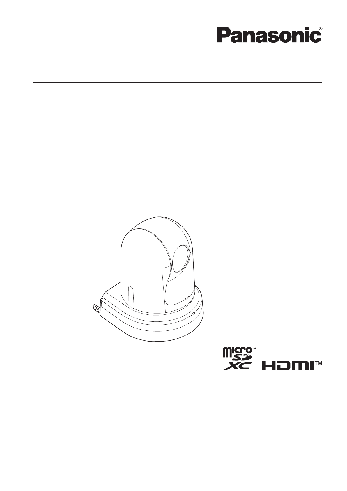
Operating Instructions
HD Integrated Camera
Model No.
Model No.
Model No.
Model No.
AW‑HE42WP
AW‑HE42KP
AW‑HE42WE
AW‑HE42KE
Before operating this product, please read the instructions carefully and save this manual for future use.
Please carefully read the “Read this first!” (pages 2 to 8) of this Manual before use.
PJ
EJ
ENGLISH
DVQP1997ZAW0519RA0 -FJ
Page 2
Read this first!
(For AW‑HE42WP, AW‑HE42KP)
CAUTION
RISK OF ELECTRIC SHOCK
DO NOT OPEN
CAUTION: TO REDUCE THE RISK OF ELECTRIC SHOCK,
REFER TO SERVICING TO QUALIFIED SERVICE PERSONNEL.
DO NOT REMOVE COVER (OR BACK).
NO USER SERVICEABLE PARTS INSIDE.
The lightning flash with arrowhead symbol,
within an equilateral triangle, is intended to
alert the user to the presence of uninsulated
“dangerous voltage” within the product’s
enclosure that may be of sufficient magnitude
to constitute a risk of electric shock to
persons.
The exclamation point within an equilateral
triangle is intended to alert the user to
the presence of important operating and
maintenance (servicing) instructions in the
literature accompanying the appliance.
WARNING:
• To reduce the risk of fire or electric shock, do not
expose this equipment to rain or moisture.
• To reduce the risk of fire or electric shock, keep
this equipment away from all liquids. Use and store
only in locations which are not exposed to the risk
of dripping or splashing liquids, and do not place
any liquid containers on top of the equipment.
CAUTION:
The mains plug of the power supply cord shall remain
readily operable.
The AC receptacle (mains socket outlet) shall be
installed near the equipment and shall be easily
accessible. To completely disconnect this equipment
from the AC mains, disconnect the power cord plug
from the AC receptacle.
CAUTION:
In order to maintain adequate ventilation, do not
install or place this unit in a bookcase, built-in cabinet
or any other confined space. To prevent risk of electric
shock or fire hazard due to overheating, ensure that
curtains and any other materials do not obstruct the
ventilation.
CAUTION:
To reduce the risk of fire or electric shock and
annoying interference, use the recommended
accessories only.
CAUTION:
Check the installation at least once a year.
An improper installation could cause the unit to fall off
resulting in personal injury.
WARNING:
Always keep memory cards (optional accessory) or
accessories (mounting screws) out of the reach of
babies and small children.
CAUTION:
This apparatus can be operated at a voltage in the
range of 100 – 240 V AC.
Voltages other than 120 V are not intended for U.S.A.
and Canada.
Operation at a voltage other than 120 V AC may
require the use of a different AC plug. Please contact
either a local or foreign Panasonic authorized service
center for assistance in selecting an alternate AC
plug.
indicates safety information.
Conforms to UL STD 60065.
Certified to CAN/CSA STD C22.2 No.60065.
CAUTION:
Do not pick up and move the unit while the tripod is
attached.
The fitting may break under the weight of the tripod,
which may result in injury.
CAUTION:
A coin type battery is installed inside of the unit.
Do not expose the unit to excessive heat such as
sunshine, fire or the like.
2
Page 3
Read this first!
(For AW‑HE42WP, AW‑HE42KP) (continued)
FCC NOTICE (USA)
Supplier’s Declaration of Conformity
Model Number: AW-HE42WP/AW-HE42KP
Trade Name: Panasonic
Responsible Party: Panasonic Corporation of North America
Two Riverfront Plaza, Newark, NJ 07102
Support contact: 1-800-524-1448
This device complies with part 15 of the FCC Rules.
Operation is subject to the following two conditions:
(1) This device may not cause harmful interference, and (2) this device must accept any interference received,
including interference that may cause undesired operation.
FCC Note:
This equipment has been tested and found to comply with the limits for a class A digital device, pursuant to Part 15
of the FCC Rules. These limits are designed to provide reasonable protection against harmful interference when the
equipment is operated in a commercial environment. This equipment generates, uses, and can radiate radio frequency
energy, and if not installed and used in accordance with the instruction manual, may cause harmful interference to
radio communications. Operation of this equipment in a residential area is likely to cause harmful interference in which
case the user will be required to correct the interference at his own expense.
Warning:
To assure continued FCC emission limit compliance, the user must use only shielded interface cables when connecting
to external units. Also, any unauthorized changes or modifications to this equipment could void the user’s authority to
operate it.
indicates safety information.
NOTIFICATION (Canada)
CAN ICES-3 (A)/NMB-3(A)
IMPORTANT SAFETY INSTRUCTIONS
1) Read these instructions.
2) Keep these instructions.
3) Heed all warnings.
4) Follow all instructions.
5) Do not use this apparatus near water.
6) Clean only with dry cloth.
7) Do not block any ventilation openings. Install in accordance with the manufacturer’s instructions.
8) Do not install near any heat sources such as radiators, heat registers, stoves, or other apparatus (including amplifiers) that
produce heat.
9) Do not defeat the safety purpose of the polarized or grounding-type plug. A polarized plug has two blades with one wider
than the other. A grounding-type plug has two blades and a third grounding prong. The wide blade or the third prong are
provided for your safety. If the provided plug does not fit into your outlet, consult an electrician for replacement of the
obsolete outlet.
10) Protect the power cord from being walked on or pinched particularly at plugs, convenience receptacles, and the point where
they exit from the apparatus.
11) Only use attachments/accessories specified by the manufacturer.
12) Use only with the cart, stand, tripod, bracket, or table specified by the manufacturer, or sold with the apparatus.
When a cart is used, use caution when moving the cart/apparatus combination to avoid injury from tip-over.
13) Unplug this apparatus during lightning storms or when unused for long periods of time.
14) Refer all servicing to qualified service personnel. Servicing is required when the apparatus has been damaged
in any way, such as power-supply cord or plug is damaged, liquid has been spilled or objects have fallen into
the apparatus, the apparatus has been exposed to rain or moisture, does not operate normally, or has been dropped.
3
Page 4
Read this first!
(For AW‑HE42WP, AW‑HE42KP) (continued)
Information on Disposal in other Countries outside the European Union
EU
These symbols are only valid in the European Union.
If you wish to discard the item(s), please contact your local authorities or dealer and ask for the correct method of
disposal.
The symbols on this product (including the accessories) represent the following.
AC
DC
Class II equipment (The construction of the product is double-insulated.)
4
Page 5
Read this first!
(For AW‑HE42WE, AW‑HE42KE)
WARNING:
• To reduce the risk of fire or electric shock, do not
expose this equipment to rain or moisture.
• To reduce the risk of fire or electric shock, keep
this equipment away from all liquids. Use and store
only in locations which are not exposed to the risk
of dripping or splashing liquids, and do not place
any liquid containers on top of the equipment.
WARNING:
Always keep memory cards (optional accessory) or
accessories (mounting screws) out of the reach of
babies and small children.
WARNING:
This equipment is compliant with Class A of
CISPR 32. In a residential environment this
equipment may cause radio interference.
CAUTION:
Do not remove panel covers by unscrewing.
To reduce the risk of electric shock, do not remove
the covers. No user serviceable parts inside.
Refer servicing to qualified service personnel.
CAUTION:
In order to maintain adequate ventilation, do not
install or place this unit in a bookcase, built-in cabinet
or any other confined space. To prevent risk of electric
shock or fire hazard due to overheating, ensure that
curtains and any other materials do not obstruct the
ventilation.
CAUTION:
To reduce the risk of fire or electric shock and
annoying interference, use the recommended
accessories only.
CAUTION:
Check the installation at least once a year.
An improper installation could cause the unit to fall off
resulting in personal injury.
CAUTION:
Do not pick up and move the unit while the tripod is
attached.
The fitting may break under the weight of the tripod,
which may result in injury.
CAUTION:
The mains plug of the power supply cord shall remain
readily operable.
The AC receptacle (mains socket outlet) shall be
installed near the equipment and shall be easily
accessible. To completely disconnect this equipment
from the AC mains, disconnect the power cord plug
from the AC receptacle.
indicates safety information.
AEEE Yönetmeliğine Uygundur
AEEE Complies with Directive of Turkey.
CAUTION:
A coin type battery is installed inside of the unit.
Do not expose the unit to excessive heat such as
sunshine, fire or the like.
5
Page 6

Read this first!
(For AW‑HE42WE, AW‑HE42KE) (continued)
EMC NOTICE FOR THE PURCHASER/USER OF THE APPARATUS
1. Pre‑requisite conditions to achieving compliance with the above standards
<1> Peripheral equipment to be connected to the apparatus and special connecting cables
• The purchaser/user is urged to use only equipment which has been recommended by us as peripheral equipment
to be connected to the apparatus.
• The purchaser/user is urged to use only the connecting cables described below.
<2> For the connecting cables, use shielded cables which suit the intended purpose of the apparatus.
• Video signal connecting cables
Use double shielded coaxial cables, which are designed for 75-ohm type high-frequency applications, for SDI
(Serial Digital Interface).
Coaxial cables, which are designed for 75-ohm type high-frequency applications, are recommended for analog
video signals.
• Audio signal connecting cables
If your apparatus supports AES/EBU serial digital audio signals, use cables designed for AES/EBU.
Use shielded cables, which provide quality performance for high-frequency transmission applications, for analog
audio signals.
• Other connecting cables
Use double shielded cables, which provide quality performance for high-frequency applications, as connecting
cables for IEEE1394 and USB.
• When connecting to the HDMI signal terminal, use multilayer shielded cables, which provide quality performance for
high-frequency applications.
• If your apparatus is supplied with ferrite core(s), they must be attached on cable(s) following instructions in this
manual.
2. Performance level
The performance level of the apparatus is equivalent to or better than the performance level required by these standards.
However, the apparatus may be adversely affected by interference if it is being used in an EMC environment, such as an
area where strong electromagnetic fields are generated (by the presence of signal transmission towers, cellular phones,
etc.). In order to minimize the adverse effects of the interference on the apparatus in cases like this, it is recommended
that the following steps be taken with the apparatus being affected and with its operating environment:
1. Place the apparatus at a distance from the source of the interference.
2. Change the direction of the apparatus.
3. Change the connection method used for the apparatus.
4. Connect the apparatus to another power outlet where the power is not shared by any other appliances.
6
Page 7
Read this first!
(For AW‑HE42WE, AW‑HE42KE) (continued)
For the AC mains plug of three pins
■Caution for AC mains lead
For your safety, please read the following text carefully.
This appliance is supplied with a moulded three pin
mains plug for your safety and convenience.
A 5-ampere fuse is fitted in this plug.
Should the fuse need to be replaced please ensure that
the replacement fuse has a rating of 5-ampere and that it
is approved by ASTA or BSI to BS1362.
Check for the ASTA mark
body of the fuse.
If the plug contains a removable fuse cover you must
ensure that it is refitted when the fuse is replaced.
If you lose the fuse cover the plug must not be used until
a replacement cover is obtained.
A replacement fuse cover can be purchased from your
local dealer.
or the BSI mark on the
Before use
Remove the connector cover.
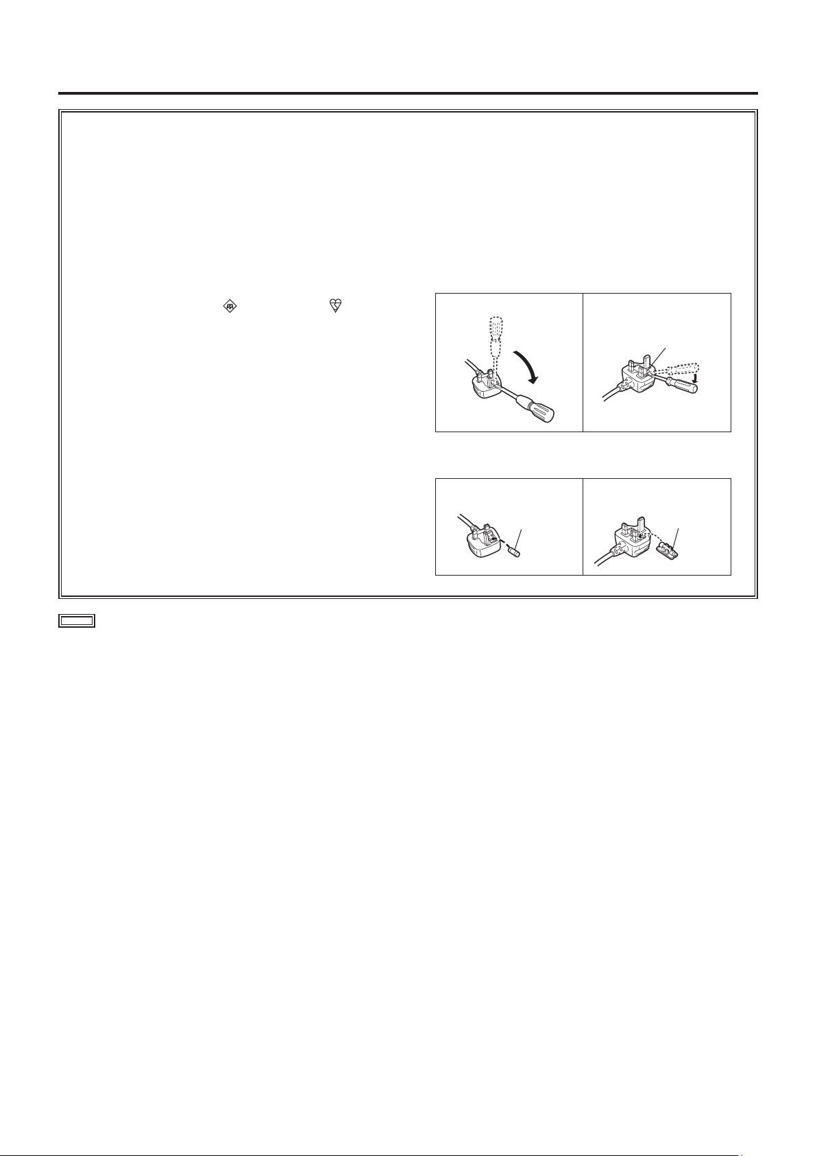
How to replace the fuse
The location of the fuse differ according to the type of AC
mains plug (figures A and B).
Confirm the AC mains plug fitted and follow the
instructions below.
Illustrations may differ from actual AC mains plug.
1. Open the fuse cover with a screwdriver.
Figure A Figure B
Fuse cover
2. Replace the fuse and close or attach the fuse cover.
Figure A
Fuse
(5 ampere)
Figure B
Fuse
(5 ampere)
indicates safety information.
7
Page 8
Read this first!
(For AW‑HE42WE, AW‑HE42KE) (continued)
Disposal of Old Equipment and Batteries
Only for European Union and countries with recycling systems
These symbols on the products, packaging, and/or accompanying documents mean that used electrical and electronic products
and batteries must not be mixed with general household waste.
For proper treatment, recovery and recycling of old products and used batteries, please take them to applicable collection points in
accordance with your national legislation.
By disposing of them correctly, you will help to save valuable resources and prevent any potential negative effects on human
health and the environment.
For more information about collection and recycling, please contact your local municipality.
EU
Back-up Battery (Lithium Battery)
For the removal of the battery for disposal at the end of its service life, please consult your dealer.
Penalties may be applicable for incorrect disposal of this waste, in accordance with national legislation.
Note for the battery symbol (bottom symbol):
This symbol might be used in combination with a chemical symbol. In this case it complies with the requirement set by the
Directive for the chemical involved.
The symbols on this product (including the accessories) represent the following.
AC
DC
Class II equipment (The construction of the product is double-insulated.)
Manufactured by: Panasonic Corporation, Osaka, Japan
Importer’s name and address of pursuant to EU rules:
Panasonic Marketing Europe GmbH
Panasonic Testing Centre
Winsbergring 15, 22525 Hamburg, Germany
8
Page 9

Contents
Read this first!
(For AW‑HE42WP, AW‑HE42KP)
Read this first!
(For AW‑HE42WE, AW‑HE42KE)
Before use
Overview
Required personal computer environment
Disclaimer of warranty
Network security
Characteristics
Accessories
Optional accessories
Operating precautions
Concerning the wireless remote control
(optional accessory)
Parts and their functions
Camera unit
Wireless remote controller (optional accessory)
Setting the remote control IDs
Network settings [When using Windows]
Use the Easy IP Setup Software to establish the
unit’s settings
Installing the plug-in viewer software
User authentication
Basic shooting operations
How to turn the power on and off
Turning the power on
Turning the power off
Priority mode (Priority Mode)
Selecting the units
Selecting the shooting modes (scene files)
Types of shooting modes
How to select the shooting mode
Shooting
What to do when encountering problems in the
basic shooting operations
More advanced operations
Manual shooting
Manually adjusting the focus
Manually adjusting the iris
Manually adjusting the shutter speed
Manually adjusting the gain
Preset memories
White balance adjustment
White balance adjustment
Black level (master pedestal) adjustment
Black level (master pedestal) adjustment
Basic setup operations
Wireless remote control operations
When performing the operations using the wireless
remote control
Camera menu items
Setting the camera menu items
Top Menu screen
Camera screen (when Full Auto is selected)
Camera screen (when Manual1 to 3 is selected)
Contrast 1/2 screen
2
5
10
11
11
12
12
13
15
15
16
18
19
19
22
24
25
25
26
27
28
29
29
29
30
31
31
31
32
33
34
35
36
36
36
37
37
38
39
39
43
43
44
44
44
45
45
45
46
47
47
Contrast 2/2 screen
Picture 1/3 screen
Picture 2/3 screen
Picture 3/3 screen
16-axis color matrix
System screen
Genlock screen
Output screen
Others 1/4 screen
Others 2/4 screen
Others 3/4 screen
Others 4/4 screen
Maintenance screen
Firmware Version screen
IP Network screen
Camera menu item table
Displaying the web screen
Displaying the web screen using a personal
computer
Switching between the Live screen [Live] and Web
setup screen [Setup]
Web screen operations
Live screen [Live] : Single display mode
Live screen [Live] : Multi display mode
Web screen configurations
Logging into the Web setup screen [Setup]
Web setup screen [Setup]
Basic screen [Basic]
Image screen [Image/Audio]
Multi screen setup screen [Multi-screen]
User management screen [User mng.]
Network setup screen [Network]
Maintenance screen [Maintenance]
Recording to and playing back
from a memory card
Web camera functions
Controllable functions
Displaying the web screen using a mobile terminal
Limiters
Basic limiter operations
Setting the limiters
Releasing the limiters
Resetting the limiters
Activation
Troubleshooting
Specifications
Index
156
67
135
137
48
50
51
52
53
54
54
55
58
59
60
61
62
62
63
64
67
68
69
75
76
77
80
124
128
128
135
136
136
136
139
151
69
74
75
100
101
103
119
131
9
Page 10
Before use
Trademarks and registered trademarks
● Microsoft®, Windows®, Windows® 7, Windows® 8,
Windows
either registered trademarks or trademarks of Microsoft
Corporation in the United States and other countries.
● Intel
trademarks of Intel Corporation in the United States and
other countries.
● Adobe
trademarks of Adobe Systems Incorporated in the United
States and/or other countries.
● The terms HDMI and HDMI High-Definition Multimedia
Interface, and the HDMI Logo are trademarks or
registered trademarks of HDMI Licensing Administrator,
Inc. in the United States and other countries.
● microSDXC Logo is a trademark of SD-3C, LLC.
● Apple, Mac, OS X, iPhone, iPod Touch, iPad, and Safari
are registered trademarks of Apple Inc., in the United
States and other countries.
● Android
● Other names of companies and products contained
in these Operating Instructions may be trademarks or
registered trademarks of their respective owners.
®
8.1, Internet Explorer® and ActiveX® are
®
and Intel® CoreTM are trademarks or registered
®
and Reader® are either registered trademarks or
TM
is a trademark of Google LLC.
About copyright and licence
Distributing, copying, disassembling, reverse compiling,
reverse engineering, and also exporting in violation of export
laws of the software provided with the unit are expressly
prohibited.
Abbreviations
The following abbreviations are used in this manual.
● Microsoft
abbreviated to “Windows 7”.
● Microsoft
“Windows 8”.
● Microsoft
“Windows 8.1”.
● Windows
Explorer
Windows
“Internet Explorer”.
● microSDHC memory cards and microSDXC memory
cards are abbreviated to “SD cards”.
For the purposes of this manual, the model numbers of the
units are given as listed in the table below.
®
Windows® 7 Professional SP1 32/64-bit is
®
Windows® 8 Pro 32/64-bit is abbreviated to
®
Windows® 8.1 Pro 32/64-bit is abbreviated to
®
Internet Explorer® 8.0, Windows® Internet
®
9.0, Windows® Internet Explorer® 10.0 and
®
Internet Explorer® 11.0 are abbreviated to
Model number
of unit
AW-HE42WP, AW-HE42KP,
AW-HE42WE, AW-HE42KE
AW-HS50N
AW-HS50E
AW-RP50N
AW-RP50E
Model number
given in manual
AW‑HE42
AW‑HS50
AW‑RP50
Illustrations and screen displays featured in
the manual
● What is shown in the manual’s illustrations and screen
displays may differ from how it is actually appears.
● The screenshots are used in accordance with the
guidelines of Microsoft Corporation.
● Functions which can be used by Windows only are
indicated using the
mark.
10
Page 11

Before use
(continued)
■Overview
● The unit is a full HD camera integrated with a pan-tilt head
and featuring a 1/2.3-type MOS sensor and digital signal
processor (DSP).
● In addition to its optical 20× zoom lens, the unit comes
with a 12× digital zoom allowing you to capture highquality images that overflow with ambience. With built-in
image stabilization, Night mode function, and ND filter, it
can record in a wide range of environments.
Further, its i.Zoom function allows up to 30× zoom while
maintaining HD quality.
● This product is compatible with NDI|HX technology of
NewTek, Inc.
● The unit supports transmission of video to NewTek
NDI|HX compatible software applications and hardware
devices over a network.
● When a controller is connected, camera operations can be
performed smoothly via IP control or serial control.
● The unit features a Night mode, making it possible to
shoot even under very-low-brightness conditions by
exposing subjects to infrared rays.
● When the unit is connected to a computer via an IP
network, it can be operated via a web browser while
viewing the camera images on the screen.
● Connection with a Panasonic camera controller is also
possible via Panasonic’s proprietary serial communication
format.
● The unit supports standard serial communication formats,
allowing connection to commercially available controllers.
● The unit is available in two color variations (white or black)
to suit your intended application and environment.
● Equipped with a codec engine, the unit can output Full HD
images at up to 60 fps via a network.
● Changing the Priority Mode enables operation for various
applications.
■Required personal computer
environment
CPU
Memory
Network
function
Image display
function
Supported
operating
system and
Web browser
When using 1080/60p [59.94Hz] and
1080/50p [50Hz]
Intel® CoreTM i7 3.4 GHz or higher
recommended
Other than above
Intel® CoreTM2 Duo 2.4 GHz or higher
recommended
For Windows:
1 GB or more
(2 GB or more for Microsoft® Windows®
8.1, Microsoft® Windows® 8, Microsoft®
Windows® 7 64-bit edition)
For Mac:
2 GB or more
10BASE-T or 100BASE-TX port × 1
Resolution: 1024 × 768 pixels or more
Color generation: True Color 24-bit or more
Windows
Microsoft® Windows® 8.1 Pro
64-bit/32-bit *1
Windows® Internet Explorer® 11.0
Microsoft
64-bit/32-bit *1
Windows® Internet Explorer® 10.0 *
Microsoft® Windows® 7 Professional SP1
64-bit/32-bit *2
Windows® Internet Explorer® 8.0 / 9.0 /
10.0 / 11.0 *
Mac
OS X v10.8
Safari 6.2
OS X v10.9
Safari 7.1
OS X v10.10
Safari 8.0
iPhone / iPad / iPod touch
iOS 8.3
Standard browser
Android
Android OS 4.4
Standard browser
®
Windows® 8 Pro
3
1
Other
1
*
: Use the desktop version of Internet Explorer. (Internet Explorer
for Windows UI is not supported.)
*2: Windows® XP compatibility mode is not supported.
*3: The 64-bit version of Internet Explorer® is not supported.
Adobe® Reader®
(for viewing the operating instructions
available on the website)
11
Page 12
Before use
(continued)
IMPORTANT
● Failure to provide the required personal computer
environment may slow down the delineation of
the images on the screen, make it impossible for
the web browser to work and cause other kinds of
problems.
● Use the desktop version of Internet Explorer. (Internet
Explorer for Windows UI is not supported.)
● For the most recent information on compatible operating
systems and web browsers, visit the support desk at the
following web site.
https://pro-av.panasonic.net/
■Disclaimer of warranty
IN NO EVENT SHALL Panasonic Corporation BE LIABLE
TO ANY PARTY OR ANY PERSON, EXCEPT FOR
REPLACEMENT OR REASONABLE MAINTENANCE OF
THE PRODUCT, FOR THE CASES, INCLUDING BUT NOT
LIMITED TO BELOW:
A ANY DAMAGE AND LOSS, INCLUDING WITHOUT
LIMITATION, DIRECT OR INDIRECT, SPECIAL,
CONSEQUENTIAL OR EXEMPLARY, ARISING OUT
OF OR RELATING TO THE PRODUCT;
B PERSONAL INJURY OR ANY DAMAGE CAUSED BY
INAPPROPRIATE USE OR NEGLIGENT OPERATION
OF THE USER;
C UNAUTHORIZED DISASSEMBLE, REPAIR OR
MODIFICATION OF THE PRODUCT BY THE USER;
D INCONVENIENCE OR ANY LOSS ARISING WHEN
IMAGES ARE NOT DISPLAYED, DUE TO ANY
REASON OR CAUSE INCLUDING ANY FAILURE OR
PROBLEM OF THE PRODUCT;
E ANY PROBLEM, CONSEQUENTIAL
INCONVENIENCE, OR LOSS OR DAMAGE, ARISING
OUT OF THE SYSTEM COMBINED BY THE DEVICES
OF THIRD PARTY;
F ANY DEMANDS FOR COMPENSATION, CLAIMS,
ETC. OCCASIONED BY THE INFRINGEMENT OF
PRIVACY BY INDIVIDUALS OR ORGANIZATIONS
WHOSE IMAGES WERE SHOT BY THE USER
BECAUSE THESE IMAGES (INCLUDING THE
RECORDINGS MADE) WERE MADE AVAILABLE
BY THE USER BECAUSE IN THE PUBLIC DOMAIN
FOR SOME REASON OR OTHER OR BECAUSE THE
IMAGES ENDED UP BEING USED FOR PURPOSES
OTHER THAN THE ONE DESCRIBED ABOVE;
G LOSS OF REGISTERED DATA CAUSED BY ANY
FAILURE.
H Indemnity about recorded content
Panasonic does not accept any responsibility for
damages directly or indirectly due to any type of
problems that result in loss of recording or edited
content, and does not guarantee any content if
recording or editing does not work properly. Likewise,
the above also applies in a case where any type of
repair is made to this unit.
■Network security
As you will use the unit connected to a network, your
attention is called to the following security risks.
A Leakage or theft of information through the unit
B Use of the unit for illegal operations by persons with
malicious intent
C Interference with or stoppage of the unit by persons
with malicious intent
It is your responsibility to take precautions such as those
described below to protect yourself against the above
network security risks.
● Use the unit in a network secured by a firewall, etc.
● If the unit is connected to a network that includes personal
computers, make sure that the system is not infected
by computer viruses or other malicious entities (using
a regularly updated antivirus program, anti-spyware
program, etc.).
● Protect your network against unauthorized access by
restricting users to those who log in with an authorized
user name and password.
● After accessing the unit as an administrator, be sure to
close all web browsers.
● Change the administrator password periodically.
● Restrict access to the unit by authenticating the users, for
example, to prevent setting information stored on the unit
from leaking over the network.
● Do not install the camera in locations where the camera or
the cables can be destroyed or damaged by persons with
malicious intent.
● Avoid connections that use public lines.
Concerning user authorization
User authentication on the unit can be performed via digest
authentication or basic authentication. If basic authentication
is used without using a dedicated line equipped with an
authentication function, password leaks may occur.
Usage restrictions
Use of the same segment is recommended for the network
in which the unit and the controller or personal computer are
connected.
If the equipment uses connections with different segments,
events based on the settings inherent to the network
equipment, for instance, may occur so check this thoroughly
prior to operation.
12
Page 13

Characteristics
Multiple number of formats supported
● You can switch between the following formats via the
camera menus or a web browser.
Supported formats:
1080/59.94p, 1080/59.94i, 1080/29.97p, 1080/29.97PsF,
720/59.94p, 1080/50p, 1080/50i, 1080/25p, 1080/25PsF,
720/50p
1/2.3‑type MOS sensor and high‑performance 20× zoom
lens featured
● A 1/2.3-type MOS sensor and DSP (digital signal
processor) are incorporated.
High-quality pictures are obtained by video processing in
many different kinds of ways.
● In addition to its optical 20× zoom lens, the unit comes
with a 12× digital zoom to achieve high-quality images that
overflow with ambiance. Further, its i.Zoom function allows
up to 30× zoom while maintaining HD quality.
● The unit is equipped with functions that allow clean
and clear reproduction of images in a wide range of
applications, such as high dynamic range (HDR) and
dynamic range stretch (DRS) functions that compensate
for overexposure and loss of dark detail and a digital noise
reduction (DNR) function that allows you to shoot scenes
clearly by minimizing image lag even in dark locations.
Easy operation of unit enabled by its integration with a
high‑performance pan‑tilt head unit
● High-speed operations with maximum speed of 300°/s
during preset, and 90°/s during manual
● Wide rotational angles with a panning range of ±175° and
a tilting range from –30° to +90°
● Quiet operation with noise levels of NC35 (normal speed)
and NC40 (during preset)
● Storage of up to 100 positions in the preset memory
(The number of preset memories that can be used varies
from one controller to another.)
Night mode incorporated
● Infrared shooting is supported.
The kind of shooting which is normally difficult under verylow-brightness conditions is now possible by exposing the
subjects to infrared rays.
(Black-and-white images are output in this case.)
● The iris will be fixed at open.
IP video output function featured
● The unit is equipped with image compression and IP
transmission LSI capabilities. IP video transmission in SD
format is possible.
In addition, output at up to 60 fps is possible for Full HD
images.
● Employing the functions of this chip together with
IP control opens the door to uses in a wide range of
applications including the control of the camera from a
remote location.
High degree of compatibility with Panasonic’s currently
available controllers, enabling a flexible system to be put
together
● A maximum of five units can be operated by serial control
from one of Panasonic’s currently available controllers
(AW-RP50).
The unit can also be used together with the cameras
and pan-tilt head unit systems currently available from
Panasonic Corporation so that an existing system can be
used to advantage to put together a system that is even
more flexible.
Notes
● It may be necessary to upgrade the version of the
controllers in order to support the unit. For details
on upgrading, visit the support page on the following
website.
https://pro-av.panasonic.net/
● The maximum distances between the units and
controller is 1000 meters (3280 ft). (when serial
control is exercised)
Use of an external device or some other means
must be provided separately in order to extend the
video signal connections.
Standard serial communication support
● Connect up to seven cameras to a commercially available
controller via RS-232C interface.
Integrated pan‑tilt head unit, camera and lens to facilitate
installation
● By designing the camera, lens and pan-tilt head as a
single integrated unit, the time taken for the installation
work has been drastically reduced.
Use of easy‑to‑operate wireless remote control (optional
accessory) is possible
● A wireless remote control capable of operating up to four
units can be used.
It can easily be used to set the various functions or switch
between them while viewing the menu screens.
13
Page 14

Characteristics
(continued)
Flexible camera layout enabled by simple connection
and installation
● The unit features excellent connectivity and installability
thanks to the IP control; a lightweight main unit, and the
turn-lock mechanism, which enables the user to install it
on his or her own (only when used indoors).
Note
● Bear in mind that the unit is designed to be used
indoors only: It cannot be used outdoors.
Easy connections and settings courtesy of IP control
● Up to a hundred units can be operated by IP connection
from a Panasonic controller (AW-RP50).
(The maximum length of the LAN cables is 100 meters
[328 ft].)
● By automatically recognizing the IP addresses and
changing their allocation, the previous restrictions on
the connections between the cameras and controllers
using serial interfaces and the time and trouble taken to
establish the various settings can be significantly reduced,
and by configuring a network, flexible camera control can
be implemented anywhere with any of the cameras.
Equipped with a high dynamic range (HDR) imaging
function
● This reduces overexposure and loss of dark detail
in images with high light-dark contrast between the
background and the subject.
Built‑in ND filter
● Built-in ND filter with 4 positions (Through, 1/4, 1/16,
1/64). This makes it easy to select the most suitable
shutter speed and aperture under varying levels of
illumination.
When “Full Auto” is selected as the setting for shooting
mode (Scene), you can select ND filter auto selection
function according to ambient light conditions.
Equipped with optical image stabilization (OIS)
● This function detects and compensates for camera shake
to reduce image blurring due to camera jitter.
High-precision camera shake compensation is provided
through an optical image stabilization with low image
degradation.
1
PoE+ *
eliminates need for camera power configurations
● Configurations for camera’s power supply are not
necessary when the unit is connected to a network
device that supports the PoE+ standard (IEEE802.3at
compliant)*
2
.
Notes
● If the AC adaptor and a PoE+ power supply are
connected simultaneously, the AC adaptor will have
priority.
● Use a category 5e cable or higher when using a
PoE+ power supply.
The maximum length of the cable between the
power supply unit and the unit is 100 meters (328 ft).
Using a cable that is lower than category 5e may
result in reduced power supply capabilities.
*1: Power over Ethernet Plus.
Referred to as “PoE+” in this manual.
*2: For details on PoE+ power supply devices for which
operation has been verified, consult your local dealer.
14
Page 15
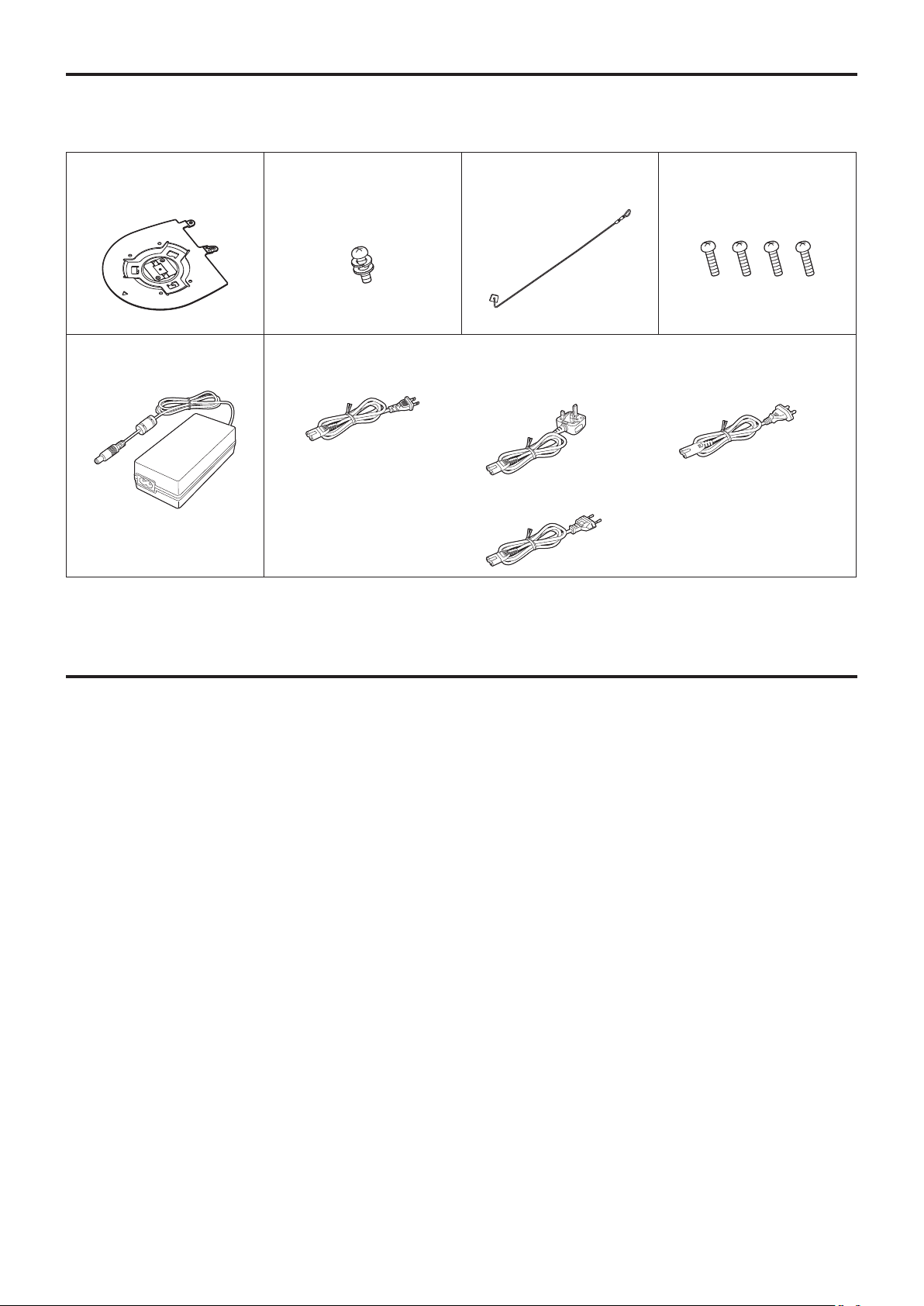
Accessories
Check that the following accessories are present and accounted for.
● After removing the product from its container, dispose of the power cable cap and packing materials in an appropriate
manner.
■ Mount bracket for installation
surface
(Hanging / Desktop) ............. 1
■ Main unit mounting screw
(with flat washer, spring
washer) M3 × 6 mm ............. 1
■ AC adaptor ........................... 1 ■ Power cable
for AW‑HE42WP,
AW‑HE42KP ................... 1
■ Drop‑prevention wire ........... 1
(already attached to the unit)
for AW‑HE42WE, AW‑HE42KE .................... 3
● For U.K. and Saudi Arabia
● For Continental Europe, etc.
■ Bracket mounting screws
(bind‑head) M4 × 10 mm ...... 4
● For India only
● This product is equipped with
3 types of AC mains cable.
Appropriate mains cable must
be used in each local area,
since the other type of mains
cable is not suitable.
Optional accessories
● Wireless remote controller AW‑RM50G
(Size “AA”, “R6” or “LR6” dry battery × 2, obtained separately)
● Direct ceiling mount bracket WV‑Q105A
15
Page 16

Operating precautions
Shoot under the proper lighting conditions.
To produce pictures with eye-pleasing colors, shoot under
the proper lighting conditions.
The pictures may not appear with their proper colors when
shooting under fluorescent lights. Select the proper lighting
as required.
To ensure a stable performance in the long term
Using the unit for prolonged periods in locations where the
temperature and humidity levels are high will cause its parts
to deteriorate, resulting in a reduction of its service life.
(Recommended temperature: Max. 35 °C [95 °F])
Ensure that a cooling unit or heating unit will not blow any air
directly toward the installation location.
Image persistence on the MOS sensor color filters
If parts of the MOS sensor are exposed continuously to
spotlights or other bright lights, the color filters inside the
MOS sensor will deteriorate, and the parts concerned may
become discolored. The discoloration may be noticeable
when the direction of fixed monitoring is changed.
Do not point the camera at strong
lights.
When parts of the MOS sensor are
exposed to spotlights or other strong
lights, blooming (a phenomenon where
the edges of strong lights become
blurred) may occur.
Bright subject
When using the automatic functions
● If “Full Auto” has been selected as the setting for Scene
on the camera menu, for example, all the auto settings
will be turned on, and manual operations will no longer be
possible for some of the items.
● When using the ATW (auto tracking white adjustment)
function under fluorescent lights, the white balance may
var y.
● In some situations, it may be hard to focus at the auto
setting. In cases like this, select the manual setting, and
focus manually.
● The appropriate brightness may not be obtained when
shooting bright objects using the auto settings for the gain
and iris.
In cases like this, set the shutter speed to manual, and
adjust.
Zooming and focusing
When the focus is set manually, out-of-focusing may occur
during zooming.
After zooming, if necessary, either adjust the focus or set the
focus to auto.
When using the focus at the manual setting, proceed with
zooming after setting the focus position at the Tele end where
the focusing accuracy is higher.
(However, if the distance from the unit to the subject is less
than 1.0 meter [3.28 ft], the subject may shift out of focus at
the Wide end.)
If zooming is performed to the Tele end after having adjusted
the focus at the Wide end, out-of-focusing may occur.
Blooming
Concerning the color reproduction of MOS sensors
Depending on the color tones of the subjects, the color
reproduction may deteriorate: This is normal and not
indicative of any trouble.
What happens with high‑brightness subjects
Flare may occur if an extremely bright light source is pointed
at the lens. In a case like this, change the angle or take some
other remedial action.
Concerning the zoom position when the power is turned
on
When the unit is turned on, the zoom, focus, and iris return
to their positions from before the unit entered standby mode.
(This happens for the focus and iris when they were set
manually.)
The operation will be performed with the [Preset Scope]
settings applied in such cases.
However, this position may not be restored if, for instance,
the power cable was disconnected during operation.
Operating temperature range
Avoid using the unit in cold locations where the temperature
drops below 0 °C (32 °F) or hot locations where the
temperature rises above 40 °C (104 °F) since these
temperatures downgrade the picture quality and adversely
affect the internal parts.
Concerning the HDMI interface standard
The unit has been certified as HDMI-compatible, but on rare
occasions images may not be displayed depending on the
HDMI device which has been connected to the unit.
16
Page 17

Operating precautions
(continued)
Color bars
Color bars are used to adjust the color phase, and the widths
and positions of these bars may differ from other models.
Concerning IP video refresh speed and operations from
the web screen
The IP video refresh speed may be reduced and operations
from the web screen may be slower, depending on the
network environment used, performance of the personal
computer or the mobile terminal, subjects and access count.
H.264 patent pool licensing
This product is licensed based on the AVC Patent Portfolio
License, and the license does not extend beyond uses by
users, who engage in the acts described below, for their own
personal and non-profit applications.
(i) Recording of image information in compliance with the
AVC standard (hereafter, “AVC videos”)
(ii) Playing of AVC videos recorded by consumers engaging
in personal activities or AVC videos acquired from
licensed providers
For details, visit MPEG LA, LLC website (http://www.mpegla.
com).
Concerning PoE+ power supply
The unit complies with the IEEE802.3at standard.
Use a PoE+ compatible Ethernet hub and injector when
using a PoE+ power supply.
For details on recommended Ethernet hubs and injectors,
consult your local dealer.
Turn off the power before connecting or disconnecting
the cables.
Always disconnect the power supply before connecting or
disconnecting cables.
Do not point the camera directly at the sun or a laser
beam no matter whether it is turned on or not.
Taking images of the sun, laser beams, or other brightly lit
subjects for prolonged periods of time may damage the MOS
sensor.
Personal computer used
If the same image is displayed for a prolonged period on a
PC monitor, the monitor may be damaged. Use of a screen
saver is recommended.
Concerning the IP address setting
Do not run the Easy IP Setup Software on a multiple number
of personal computers for a single camera and set the IP
address at the same time.
Otherwise, you will be unable to complete the proper
procedure and set the IP address correctly.
Do not allow foreign matter to make contact with the
rotating parts.
Otherwise, trouble may be caused.
Keep the unit away from water.
Avoid all direct contact with water. Otherwise, problems may
occur.
Maintenance
Disconnect the power supply before proceeding with
maintenance.
Otherwise, you may injure yourself.
Wipe the surfaces using a soft dry cloth. Avoid all contact
with benzine, paint thinners and other volatile substances,
and avoid using these substances. Otherwise, the casing
may become discolored.
Handle the unit carefully.
Do not drop the unit or subject it to strong impact or vibration.
Doing so may cause the unit to malfunction.
When the unit is not in use
Turn off the unit’s power when it is not in use.
When the unit is no longer going to be used, do not leave it
lying around, but be absolutely sure to remove it properly.
Do not touch the optical system parts.
The optical system parts are the very heart of the camera.
Under no circumstances must they be touched.
In the unlikely event that they have become dusty, remove
the dust by using a camera blower or by wiping them gently
with a lens cleaning paper.
Do not turn the camera head by hand.
Turning the camera head by hand may cause the unit to
malfunction.
Use the unit in an environment with minimal moisture
and dust.
Avoid using the unit in an environment with high
concentration of moisture or dust since these conditions will
damage the internal parts.
Disposal of the unit
When the unit has reached the end of its service life and is
to be disposed of, ask a qualified contractor to dispose of the
unit properly in order to protect the environment.
17
Page 18
Concerning the wireless remote control (optional accessory)
The unit can be operated by remote control using a
wireless remote control (model number: AW‑RM50G)
purchased separately.
Check out the following points before using the wireless
remote control.
● Point the wireless remote control at the unit’s wireless
remote control signal light‑sensing area (front
panel or side panel), and operate it within a range of
10 meters (32.8 ft) from these areas.
Refer to <Layout of wireless remote control signal
light‑sensing areas> shown below.
● If the unit is installed near fluorescent lights, plasma
monitors or other such products or if the unit is
exposed to sunlight, the effects of the light may make
it impossible for the unit to be operated using the
wireless remote control.
Be sure to follow the steps below for installation and use.
• Take steps to ensure that the wireless remote control
signal light-sensing area will not be exposed to the light
from fluorescent lights, plasma monitors or other such
products or from the sun.
• Install the unit away from fluorescent lights, plasma
monitors and other such products.
● For about 10 minutes even after the batteries have
been removed from the wireless remote control,
the selection of the operation to be performed (the
[CAM1], [CAM2], [CAM3] or [CAM4] button which was
pressed last) will remain stored in the memory. When
a longer period of time elapses, however, the selection
is reset to the status established when the [CAM1]
button was pressed.
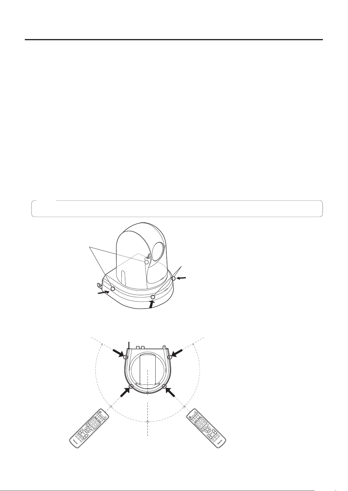
<Layout of wireless remote control signal light‑sensing areas>
Note
● The arrows in the figure below show the light-sensing directions in which the wireless remote control signals travel.
Wireless remote control signal
light‑sensing area
(side panel, 2 places)
● Top view
75°
Wireless remote control signal
light‑sensing area (front panel, 2 places)
(Back)
75°
(Front)
45°45°
18
Page 19
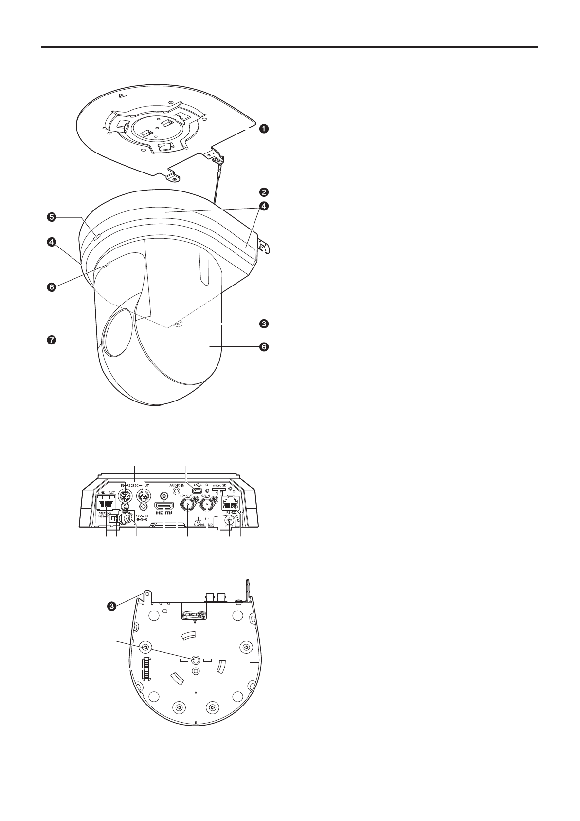
Parts and their functions
■Camera unit
<Rear panel>
a Mount bracket for installation surface
(supplied accessory)
Mount this bracket onto the installation surface, and then
attach the camera main unit to the bracket.
b Drop‑prevention wire
Pull out the wire from the bottom panel of the camera
main unit, and attach it to the hook of the mount bracket.
c Hole for securing the camera pedestal
This hole is provided in the bottom panel of the camera
pedestal.
d Wireless remote control signal light‑sensing
area
Light sensors are located in four places; at the front of the
camera pedestal and on either side.
e Status display lamp
This lights in the following way depending on the status of
the unit.
Orange: When the standby status is established
Green: When the power is on
Red: When trouble has occurred in the unit
Green and blinks twice:
When a signal matched by the remote control
ID has been received from the wireless remote
control (optional accessory) while the power is
on
Orange and blinks twice:
When a signal which is not matched by the
remote control ID has been received from the
wireless remote control (optional accessory)
while the power is on
<Bottom panel>
f Camera head
This rotates in the horizontal direction.
g Lens unit
This rotates in the up and down direction.
h Tally lamp
This comes on or goes off in response to the control from
the controller but only when “On” has been selected as the
tally lamp use setting.
19
Page 20
Parts and their functions
1 3 5 7
(continued)
i LAN connector for IP control [LINK/ACT]
This LAN connector (RJ-45) is connected when exercising
IP control over the unit from an external device.
Use a cable with the following specifications for the
connection to the LAN connector:
When connecting through a hub:
LAN cable* (category 5 or above),
max. 100 meters [328 ft]
When using a PoE+ compatible hub:
LAN cable* (category 5e or above),
max. 100 meters [328 ft]
When a hub is not used:
LAN cable* (category 5 or above),
max. 100 meters [328 ft]
*: Use of an STP (shielded twisted pair) cable is
recommended.
j Anti‑theft wire mounting hole
Use this hole to attach the wire bracket (commercially
available).
k Audio input connector [AUDIO IN]
Inputs external audio (microphone, line).
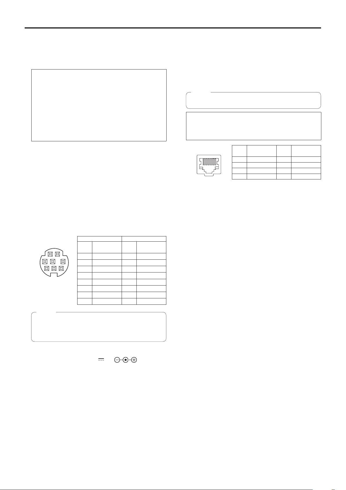
p RS‑422 connector [RS‑422]
This RS-422 connector (RJ-45) is connected when
exercising serial control over the unit from an external
device.
Use a cable with the following specifications for the
connection to this connector.
The tally lamp can be lit by shorting the TALLY signal (pin
2) with GND (pin 1).
Note
● Do not apply a voltage to the TALLY signal pin.
LAN cable* (category 5 or above, straight cable), max.
1000 meters [3280 ft]
*: Use of an STP (shielded twisted pair) cable is
recommended.
2 4 6 8
Pin
No.
Signal
1 GND 5 TXD +
2 TALLY 6 RXD +
3 RXD – 7 —
4 TXD – 8 —
q USB port
The unit can be used as a Web camera by connecting the
unit and a personal computer with USB Video Class.
Pin
No.
Signal
l RS‑232C connectors [RS‑232C IN/OUT]
Connect to RS-232C cables.
RS‑232C IN/OUT
connector
1 2
4
3
7
6
8
● Mini DIN 8‑pin
(JST)
5
RS‑232C IN RS‑232C OUT
Pin
No.
1
2
3
4
5
6
7
8
Signal
DTR_IN
DSR_IN
TXD_IN
GND
RXD_IN
GND
IR OUT R
IR OUT L
Pin
No.
1
2
3
4
5
6
7
8
DTR_OUT
DSR_OUT
TXD_OUT
GND
RXD_OUT
GND
NC
NC
Signal
Note
● Be aware that the polarities (+/−) of the serial data
may be different depending on the specifications of
the device to be connected.
m DC IN connector [12V IN ]
Connect the AC adaptor supplied with the unit to this
connector to supply the DC 12 V voltage to the unit.
r microSD card slot
The video and audio of the camera can be recorded to a
microSD card in MP4 format.
s Threaded hole (thread: 1/4‑20UNC, ISO1222
[6.35 mm]) for mounting the camera
Use this hole when mounting the camera on a tripod, etc.
t HDMI connector [HDMI]
This is the HDMI video signal output connector.
For limitations that pertain when simultaneously outputting
HDMI and SDI signals, refer to page 55.
u SDI OUT connector [SDI OUT]
This is the SDI video signal output connector.
For limitations that pertain when simultaneously outputting
HDMI and SDI signals, refer to page 55.
n Cable clamp
This is used to hold the cable connection to the DC IN
connector and prevent it from becoming disconnected.
o Ground connector
Connects to the ground connector on a wall outlet,
ground bar, etc. for grounding. (Installation Instructions →
“Connections” → “Note on grounding”)
20
Page 21
Parts and their functions
(continued)
v G/L IN connector [G/L IN]
This is the external sync signal input connector.
This unit supports BBS (Black Burst Sync) and tri-level
synchronization.
External synchronization (genlock) can be applied to
achieve phase alignment when multiple cameras are to
be used or when the unit is to be used in combination with
other devices.
Supply to this connector the sync signals that correspond
to the video signal format which has been set.
Format
1080/59.94p
1080/29.97p
1080/59.94i
1080/29.97PsF
720/59.94p
1080/50p
1080/25p
1080/50i
1080/25PsF
720/50p
● External synchronization is performed using the SDI video
signal. Synchronization is not possible using the HDMI video
signal or the IP video signal.
For horizontal phase adjustment, refer to “Genlock screen”
(page 54).
External sync signal input format
BBS Tri‑level sync
480/59.94i
480/59.94i
480/59.94i
480/59.94i
480/59.94i
576/50i
576/50i
576/50i
576/50i
576/50i
1080/59.94i
1080/59.94i
1080/59.94i
720/59.94p
1080/50i
1080/50i
1080/50i
720/50p
—
—
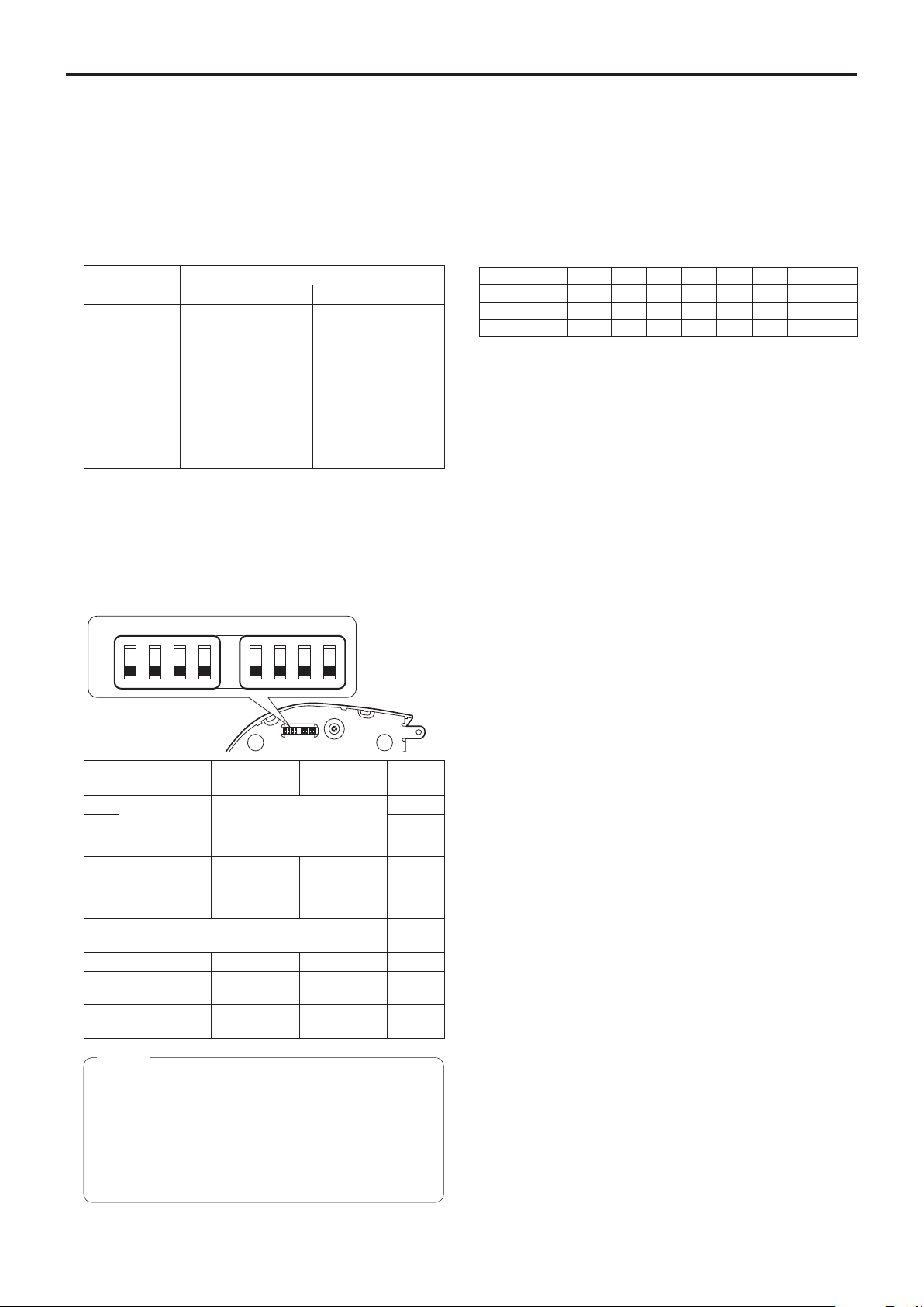
w Service switches
SW1
SW2 SW3 SW4 SW5 SW6 SW7 SW8
ON
OFF
Service switch settings
(1) SW1 to SW3: Camera address setting switches
Configure the camera address.
Set this to AUTO under normal circumstances. When
cameras are set to AUTO, addresses will be assigned to
the cameras automatically in response operation from
the controller in the order in which the cameras were
connected.
To manually configure the address, set the switches as
follows.
Address AUTO 1 2 3 4 5 6 7
SW1 OFF ON OFF ON OFF ON OFF ON
SW2 OFF ON ON OFF OFF ON ON OFF
SW3 OFF ON ON ON ON OFF OFF OFF
(2) SW4: Communication format selection switch
Selects the communication format.
When this is set to ON, standard serial communication is
enabled.
When this is set to OFF, Panasonic’s proprietary serial
communication is enabled.
(3) SW5: Maintenance switch
Fixed at OFF.
Do not change this switch setting.
(4) SW6: Infrared output switch
When this is set to ON, infrared output is enabled. The
signal received via the remote control sensor is output
from pins 7 and 8 of the RS-232C IN connector.
Signal output is disabled when this is set to OFF.
(5) SW7: Communication baud rate switch
When this is set to ON, the baud rate is 38400 bps.
When this is set to OFF, the baud rate is 9600 bps.
Function OFF ON
SW1 Camera
address setting
SW2 OFF
(standard serial
SW3 OFF
communication)
Communication
SW4
format
Always leave at OFF (used for factory
SW5
adjustments)
SW6 Infrared output Disable Enable OFF
Communication
SW7
baud rate
Communication
SW8
connector
See descriptions for SW1 to
SW3
Panasonic
proprietary
serial
communication
9600 bps 38400 bps OFF
RS-422 RS-232C OFF
Standard serial
communication
Factory
setting
OFF
OFF
OFF
Notes
● Perform switch settings before turning the unit on.
● Cameras whose camera address setting switches
are set to AUTO cannot coexist with cameras whose
switches are set to 1 to 7.
● Manually setting multiple cameras to the same
address will not allow you to control multiple
cameras from a single controller simultaneously.
(6) SW8: Communication connector switch
When this is set to ON, RS-232C is enabled.
When this is set to OFF, RS-422 is enabled.
21
Page 22
Parts and their functions
(continued)
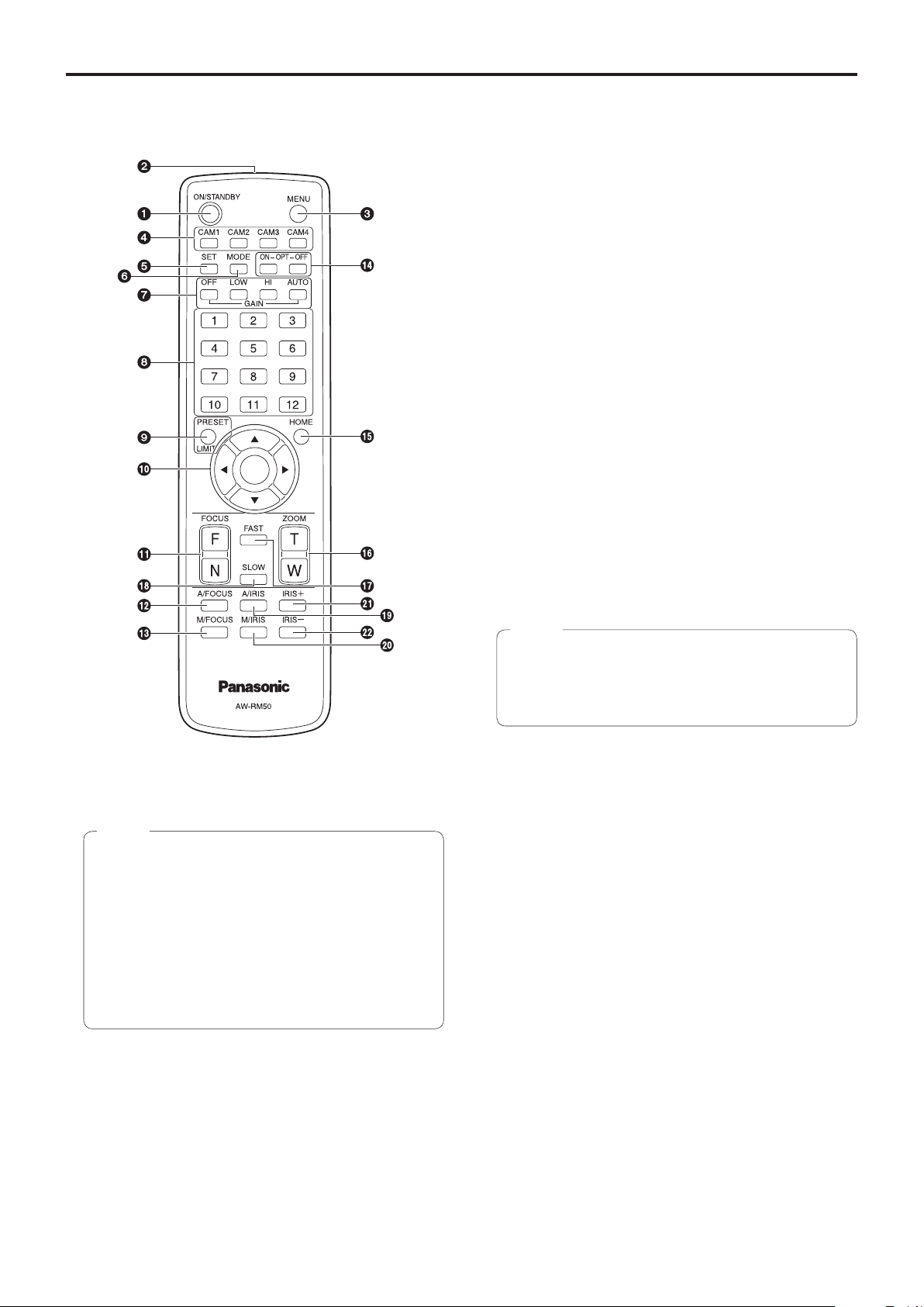
■Wireless remote controller
(optional accessory)
c MENU button
Each time this is pressed for 2 seconds, operation
switches between displaying the unit’s camera menu and
exiting the camera menu.
When it is pressed quickly (for less than 2 seconds) while
a menu is displayed, the setting change is canceled.
Furthermore, the pan and tilt movement range limits
(limiters) are set and released by operating the MENU
button, PRESET/LIMIT button and the pan-tilt buttons
([▲], [▼], [◄] and [►]).
For details, refer to “Limiters” (page 135).
d CAM1 to CAM4 buttons
These are used to select the units that are to be operated.
Once a button has been selected, the unit corresponding
to the selected button can be operated.
e SET button
If this button is pressed when one of the “Manual1 to 3”
settings has been selected for “Scene” on the camera
menu and the AWB A memory or AWB B memory has
been selected by the white balance adjustment, the white
balance is automatically adjusted and registered in the
selected memory.
f MODE button
This is used to select the video signals which are output
from the unit.
Each time it is pressed, the signals are switched between
the color bar signals and camera video signals.
Note
● When the color bar is displayed, a test tone (1 kHz)
is output according to the Audio setting in the
camera menu.
Be cautious of the volume on external devices.
a ON/STANDBY button
Each time this is pressed for 2 seconds, operation
switches between turning on the unit’s power and
establishing the standby status.
Notes
● When operation is transferred to the standby mode:
The current pan-tilt position is stored in the memory
(as a POWER ON preset), and the panning/tilting
moves so that the camera points in the backwardfacing direction.
● When operation is transferred to the POWER ON
mode: Panning/tilting moves to the position which
was stored in the memory (as a POWER ON preset)
when operation was transferred to the standby
mode.
b Signal transmission window
g GAIN buttons [OFF] [LOW] [HI] [AUTO]
These are used to set the gain.
The gain increase can be set in three steps using the
[OFF], [LOW] and [HI] buttons.
[OFF] is set to 0 dB, [LOW] is set to 9 dB, and [HI] is set
to 18 dB.
When the [AUTO] button is pressed, the AGC function
is activated, and the gain is adjusted automatically
depending on the light quantity.
The maximum gain of the AGC function can be set using
the camera menu.
h Preset memory call buttons [1] to [12]
These are used to call the information on the unit’s
directions and other settings, which have been registered
in the unit’s preset memories No.1 to No.12, and
reproduce those settings.
Settings in preset memories No.13 and above cannot be
called from the wireless remote control.
22
Page 23

Parts and their functions
(continued)
i PRESET/LIMIT button
This is used to register the settings in the preset
memories or set or release the limiters.
When a preset memory call button is pressed while the
PRESET/LIMIT button is held down, the information on
the unit’s current direction and other settings is registered
in the call button.
Preset memory call buttons [1] to [12] correspond to the
unit’s No.1 to No.12 preset memories.
Furthermore, the pan and tilt movement range limits
(limiters) are set and released by operating the PRESET/
LIMIT button, MENU button and the pan/tilt buttons ([▲],
[▼], [◄] and [►]).
For details, refer to “Limiters” (page 135).
j Pan‑tilt buttons and menu operation buttons
[▲] [▼] [◄] [►] [
(1) These are used to change the unit’s direction.
The unit is tilted in the up/down direction using the [▲]
and [▼] buttons and panned in the left/right direction
using the [◄] and [►] buttons.
The [
] button does not work during tilting and
○
panning.
When the [▲] or [▼] and [◄] or [►] buttons are
pressed at the same time, the unit moves diagonally.
(2) The buttons are used for menu operations when the
unit displays the camera menus.
Use the [▲], [▼], [◄] and [►] buttons to select the
menu items.
When a selected item has a sub-menu, the sub-menu
will be displayed by pressing the [
When the cursor is aligned with a particular item and
the [
] button is pressed on the setting menu at the
○
bottom hierarchical level, the setting of the selected
item blinks.
When the [
has been changed using the [▲], [▼], [◄] and [►]
buttons, the setting stops blinking, and the new setting
is entered.
With a regular menu, the new setting is reflected
immediately after it has been changed if the change
was made from the setting in the blinking status, but
there are some menus (Scene, Format and Initialize)
where it is reflected only after the [
pressed, the blinking has stopped and the new setting
has been entered.
If the MENU button is pressed quickly (for less than
2 seconds) while the setting is in the blinking status,
the change will be canceled, and the setting selected
prior to the change will be restored.
] button is pressed after the setting
○
○
]
] button.
○
] button has been
○
k FOCUS buttons [F] [N]
These are used to adjust the lens focus manually when
the manual setting is established for the lens focus.
The focus is adjusted in the far using the [F] button and in
the near using the [N] button.
m M/FOCUS button
This is used when manually adjusting the lens focus.
The FOCUS buttons ([F] and [N]) are used when
performing the actual adjustment.
n OPT buttons [ON] [OFF]
This is used to select the Day mode or Night mode.
[ON]: Night mode
[OFF]: Day mode (standard setting)
o HOME button
When this is pressed for 2 seconds, the unit’s direction
(panning or tilting) returns to the reference position.
p ZOOM buttons [T] [W]
These are used to adjust the lens zoom.
The zoom is adjusted in the wide-angle using the [W]
button and in the telephoto using the [T] button.
q FAST button
This is used to change the movement speed at which
the panning, tilting, zooming and focusing operations are
performed to the high speed.
When the button is tapped, the movement speed can be
set to the normal high-speed operation. When the button
is held down, it can be set to an even faster high-speed
operation. Tap the button to return the movement speed to
the normal high-speed operation.
Note
● The operating speed for panning and tilting when
the preset memory settings have been called can be
changed using the Preset Speed item and Preset
Speed Table item of the camera menu.
r SLOW button
This is used to change the movement speed at which
the panning, tilting, zooming and focusing operations are
performed to the low speed.
When the button is tapped, the movement speed can be
set to the normal low-speed operation. When the button
is held down, it can be set to an even slower low-speed
operation. Tap the button to return the movement speed to
the normal low-speed operation.
s A/IRIS button
This establishes the setting for adjusting the lens iris
automatically in line with the light quantity.
t M/IRIS button
This establishes the setting for adjusting the lens iris
manually.
The IRIS + and IRIS – buttons are used when performing
the actual adjustment.
u IRIS + button
This is used to adjust the lens iris in the opening direction.
l A/FOCUS button
This is used when automatically adjusting the lens focus.
v IRIS – button
This is used to adjust the lens iris in the closing direction.
23
Page 24
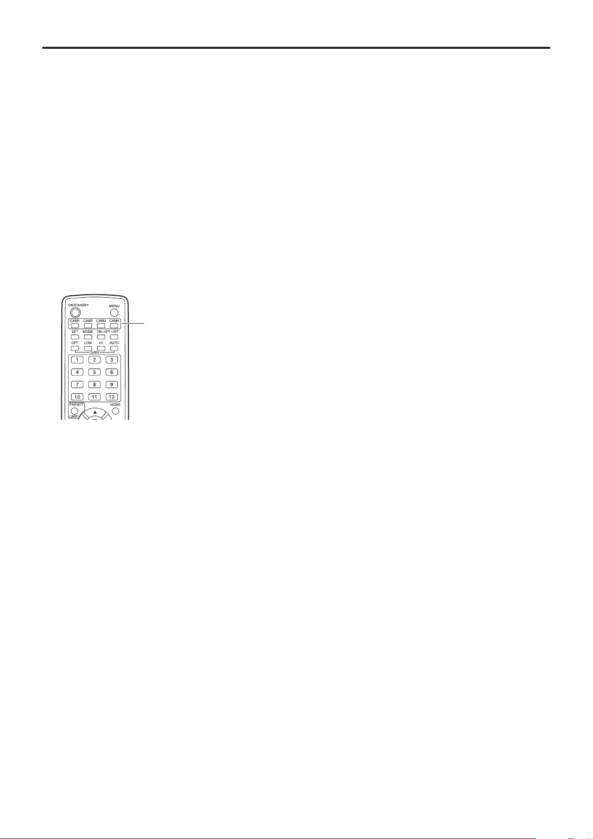
Setting the remote control IDs
The wireless remote control (optional accessory) is capable
of operating up to four units.
IDs are used to set which units are selected when the
[CAM1], [CAM2], [CAM3] and [CAM4] buttons on the
wireless remote control have been pressed.
● When operating a multiple number of these units using
wireless remote controls, set a different remote control ID
for each control.
● When using one unit, set the remote control ID to “CAM1”
unless the setting needs to be changed.
Setting procedure
Operate the unit’s camera menu or the web screen to select
a remote control ID ([CAM1] to [CAM4]).
The camera’s [CAM1] to [CAM4] settings correspond to the
[CAM1] to [CAM4] buttons on the wireless remote control.
(The factory setting is “CAM1”.)
For details, refer to “IR ID” (page 60, page 99).
[CAM1] to [CAM4] buttons
24
Page 25
Network settings [When using Windows]
■Use the Easy IP Setup Software
to establish the unit’s settings
The settings related to the unit’s network can be established
using the Easy IP Setup Software supplied.
You can obtain Easy IP Setup Software (EasyIPSetup.exe)
by downloading it from the following website.
https://pro-av.panasonic.net/
To establish the settings for a multiple number of units, the
settings must be selected for each camera involved.
If the settings cannot be established using the Easy IP Setup
Software, select the settings separately for the unit and
personal computer on the Network setup screen [Network] of
the setting menu. (page 103)
Notes
● If, after the network settings have been established,
another device in the same network has the same IP
address, the network operations will not be performed
properly.
Set the IP address in such a way that it does not
duplicate an existing IP address.
● Do not establish network settings from a multiple
number of Easy IP Setup Software programs at the
same time for a single camera.
Similarly, do not perform the “Auto IP setting” operation
of the remote camera controller (AW-RP50) at the
same time.
The IP address settings may no longer be recognized
as a result.
● When you start the Easy IP Setup Software, you may
be asked for the administrator account password.
● To enhance security, the Easy IP Setup Software is
designed so that when around 20 or more minutes
have passed after the power was turned on, the
network settings of the target camera can no longer be
configured. (When the [Easy IP Setup accommodate
period] setting is [20min] → page 105)
● The Easy IP Setup Software cannot be used from a
different subnet via a router.
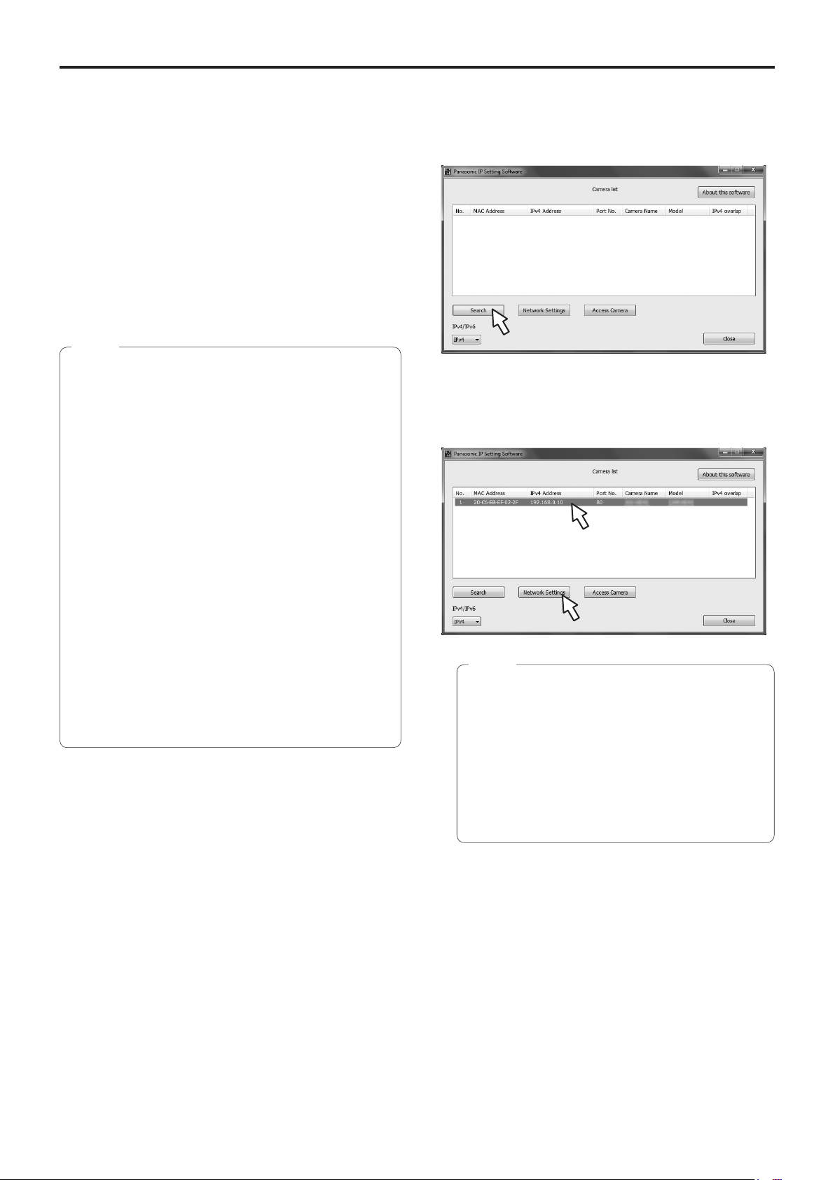
1 Start the Easy IP Setup Software.
2 Click the [Search] button.
3 Click the MAC address/IPv4 address of the
camera to be set, and click the [Network
Settings] button.
Notes
● When a DHCP server is being used, the IP
address allocated to the unit can be checked by
clicking the [Search] button of the Easy IP Setup
Software.
● If the same IP address is used for any additional
cameras, the numbers of the additional cameras
will be displayed in the “IPv4 overlap” column of
the cameras concerned.
● When the [Access Camera] button is clicked, the
Live screen of the selected camera is displayed.
25
Page 26
Network settings [When using Windows]
(continued)
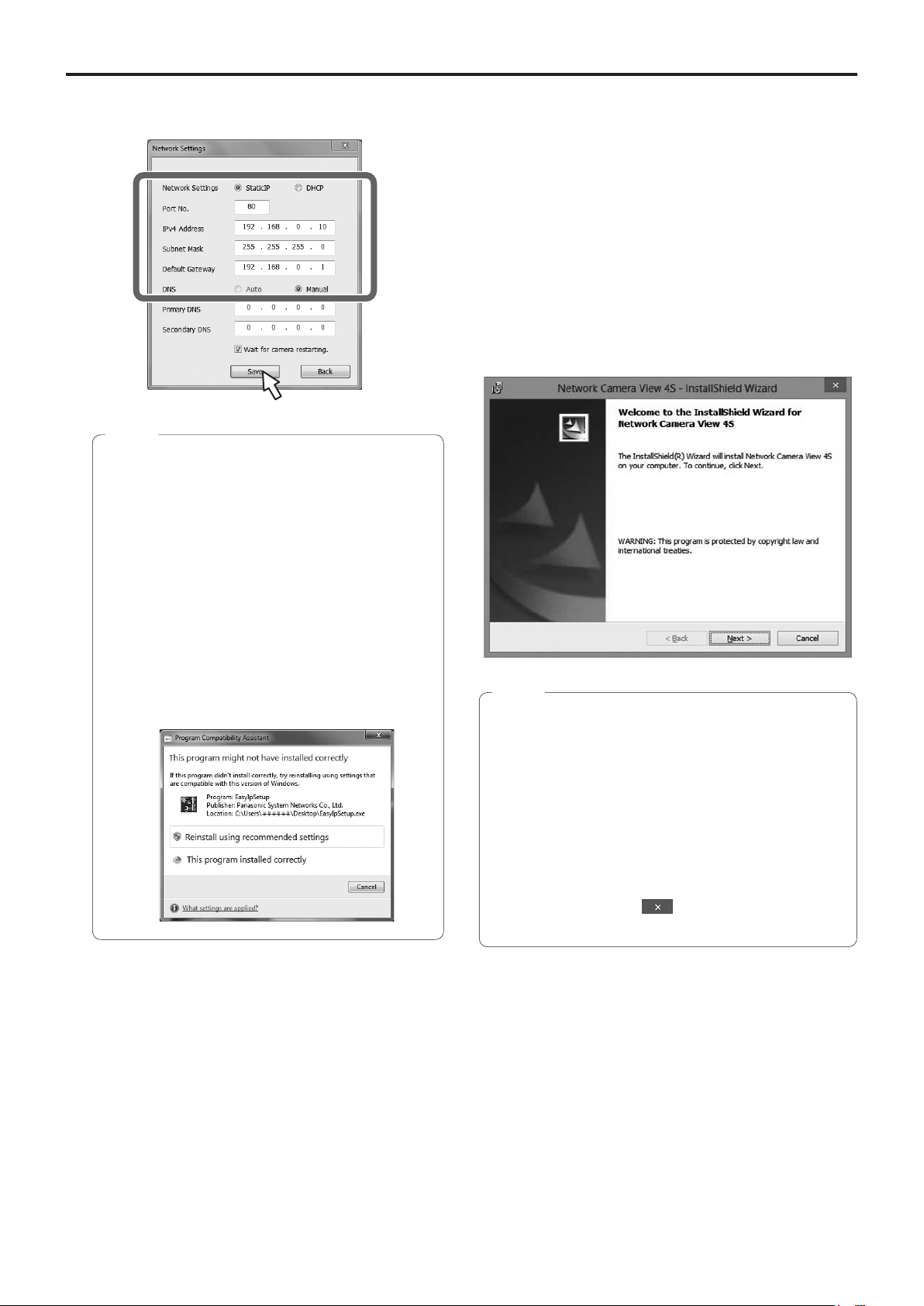
4 Input the network items, and click the [Save]
button.
Notes
● When a DHCP server is being used, “DNS” of the
Easy IP Setup Software can be set to “Auto”.
● After the [Save] button is clicked, it takes
about 1 minute for the settings in the unit to be
completed. If the AC adaptor or LAN cable is
disconnected before the settings are completed,
the settings will be canceled. In this case, repeat
the steps to establish the settings.
● When a firewall (including software) has been
introduced, enable access to all the UDP ports.
● When the Easy IP Setup Software is used for the
first time, the [Program Compatibility Assistant]
screen may appear after quitting the Easy IP Setup
Software.
Select [This program installed correctly] in the
[Program Compatibility Assistant] screen.
■Installing the plug‑in viewer
software
To view IP images from the unit on a web browser, the
“Network Camera View 4S” plug-in viewer software
(ActiveX
®
) must be installed in your personal computer.
● When you display the Live screen [Live] on the personal
computer for the first time, the installation screen for the
plug-in viewer software (ActiveX) appears. Follow the
instructions on the screen to perform installation.
● Depending on the operating environment of your
computer, you may need to start Internet Explorer with an
administrator account during installation.
(Startup with an administrator account will not be required
after installation is complete.)
Notes
● [Automatic installation of viewer software] is set to
[On] at the time of purchase, allowing you to install
directly from the unit. If a message appears in the web
browser’s information bar, refer to page 150.
● If the plug-in viewer software (ActiveX) installation
screen continues to appear when switching screens,
even after it is installed, restart the personal computer.
● To uninstall the plug-in viewer software, select [Control
Panel] - [Programs] - [Uninstall a program] in Windows,
and remove “Network Camera View 4S”.
● If installation of the plug-in viewer software fails, close
Internet Explorer with
displayed and then click [Next].
while the above screen is
26
Page 27
Network settings [When using Windows]
(continued)
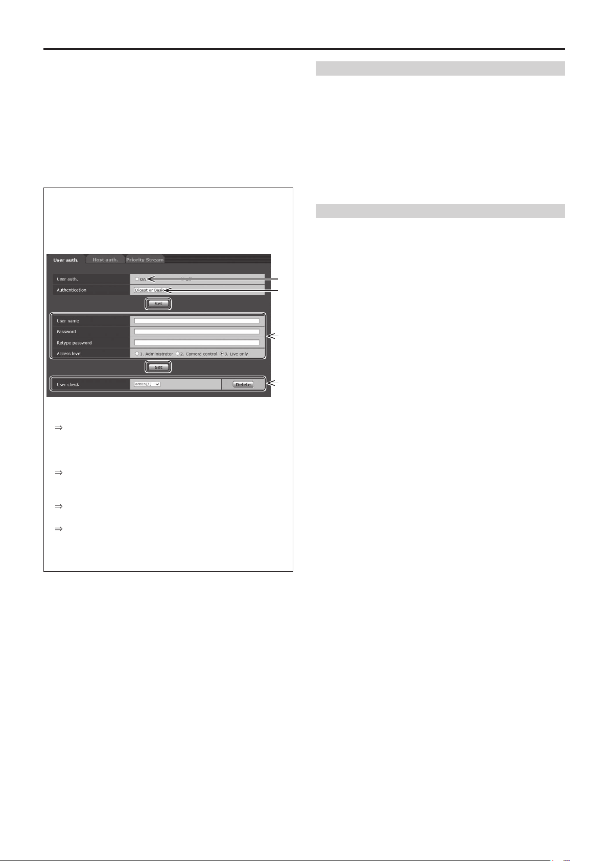
■User authentication
The unit can be configured to allow access from the
internet. To prevent infringement of privacy and personality
rights, information leaks, and other issues concerning
unauthorized access by third parties, we recommend
enabling the user authentication function upon installation.
We also recommend using DIGEST authentication when
connecting to a device that supports DIGEST authentication.
• The AW-RP50 supports DIGEST authentication.
Preparation:
1. Startup the web browser and display the “Live” page on
a PC.
2. Click “Setup” button and then click “User mng.” button.
The user authentication window will be displayed.
A
B
C
User name and password management
• Use a combination of characters and numbers that is
difcult to guess.
Avoid using a string of the same characters, such as
“11111”, birth dates, or telephone numbers.
For details on valid characters and lengths, refer to “User
authentication settings tab [User auth.]” (page 101).
• Change user names and passwords periodically.
• Make sure to manage the congured user names and
passwords.
• Delete all user names that do not have an assigned
user.
After changing the user name/password
Also change the user names and passwords registered to
the following.
Refer to the operating instructions provided with your camera
for further information about the settings used for your
camera.
• Remote camera controller (AW-RP50)
• Browsers and applications on computers, tablets, and
smartphones.
A Select “On” for “User auth.”
* Set to “Off” by default.
Then click “Set” button.
B (When using a device that supports DIGEST
authentication)
Select “Digest” for “Authentication”.
Then click “Set” button.
C Register a new user name and password
* Select “1. Administrator” for the access level.
Then click “Set” button.
D Delete the default user name.
Click the “Delete” button after selecting the user name
to be deleted (“admin[1]”).
* Depending on the model used, the screens shown in the
explanations may differ to the actual camera screens.
D
27
Page 28

Basic shooting operations
1 Set the subject brightness to the appropriate
level.
2 Turn on the power of all the units and devices
in the system.
3 Select the unit to be operated.
Even when using only one unit, it must still be selected
from the wireless remote control or controller.
4 Select the shooting mode.
Select one of the four (Full Auto, Manual1, Manual2 and
Manual3) preset shooting modes (scene files), each of
which corresponds to a set of circumstances in which
the subject will be shot.
Select the mode that satisfies the shooting conditions
and suits your preferences.
When continuing to shoot in the same circumstances,
there is no need to select another mode.
5 Start shooting.
(After shooting, turn off the power of all the
units and devices in the system.)
With the basic operations, it is assumed that the focus, iris
and white balance will be adjusted automatically (as per the
factory settings).
If the settings have already been changed and the original
settings are to be restored, refer to the “What to do when
encountering problems in the basic shooting operations”
(page 34) and “Camera screen” (page 46) in “Camera
menu items”.
Note
● If “Full Auto” has been selected as the setting for
Scene on the camera menu, for example, all the auto
settings will be turned on, and manual operations will
no longer be possible for some of the items.
28
Page 29

How to turn the power on and off
■Turning the power on
When performing the operations
using the wireless remote control
1 Set all the power switches of the units and
devices connected in the system to ON.
● The unit does not have a power switch.
When power is supplied to it, the status display lamp
will light up orange.
Note
● When the camera is turned on for the first time after
purchase, it enters the STANDBY mode.
2 Press one of the [CAM1] to [CAM4] buttons on
the wireless remote control to select the unit.
3 Press the [ON/STANDBY] button on the
wireless remote control for 2 seconds.
The POWER ON mode is established, images are
output, and control can be exercised.
● The unit’s status display lamp now lights up green.
Notes
● It takes about 30 seconds per unit for the initial
settings operation to be completed. During this
period, the unit cannot be operated.
● The unit stores its STANDBY / POWER ON mode
status in the memory.
● If the power supply is cut off while the operation is in
POWER ON mode, the operation will transferred to the
POWER ON mode the next time power is supplied.
● When transferring to the STANDBY mode
(Status display lamp: Orange)
The pan/tilt position is stored in the memory, and the
pan/tilt unit is moved so that it points backwards.
● When transferring to the POWER ON mode
(Status display lamp: Green (after the initial setting
operation is completed))
The pan/tilt unit is moved to the position which was
stored in the memory when the transition to the
STANDBY mode was made.
● POWER ON preset
The pan/tilt unit is moved to the setting, which was
established immediately prior to the transition to the
STANDBY mode, when the power has been turned on.
● If the power is turned off without transferring to the
STANDBY mode, the pan/tilt unit position will not
be stored in the memory or reflected in the POWER
ON preset. The previous POWER ON preset will be
applied.
■Turning the power off
When performing the operations
using the wireless remote control
1 Press one of the [CAM1] to [CAM4] buttons on
the wireless remote control to select the unit.
2 Press the [ON/STANDBY] button on the
wireless remote control for 2 seconds.
The unit enters STANDBY mode.
● The unit’s status display lamp now lights up orange.
3 If a multiple number of units are used, repeat
1 and 2 as required.
steps
4 Set all the power switches of the units and
devices connected in the system to OFF.
When performing the operations using the controller
When using an AW‑RP50:
Refer to the Operating Instructions of the controller.
4 If a multiple number of units are going to be
used, repeat steps
The unit’s status display lamp blinks green when a signal
matched by the remote control ID has been received, and
it blinks orange when a signal that is not matched by the
remote control ID has been received.
2 and 3 as required.
29
Page 30

Priority mode (Priority Mode)
Changing the priority mode enables the unit to perform operation for various applications. (page 56, page 77)
IP:
Enables IP image transmission over multiple channels. The IP transmission of H.264 images is also supported.
SD card:
Inserting an SD card (optional accessory) into the unit enables recording H.264 images to the SD card.
The data recorded to the SD card can be played back on the Web screen, downloaded to a personal computer, and
transferred to an FTP server.
USB:
Enables the unit to be used as a Web camera.
The camera can also be controlled from a personal computer.
NDI|HX:
Transmits video to NewTek NDI compatible software applications and hardware devices over a network.
The function supports H.264/IP transmission using NDI|HX.
Functions that can be and functions that cannot be controlled simultaneously
Priority Mode MJPEG IP streaming H.264 IP streaming
IP
SD card
USB
1920×1080
1280×720
640×360
320×180
640×360
320×180
640×360
320×180
1920×1080
1280×720
640×360
320×180
—
— —
Recording MP4 to SD
card
— —
1920×1080
1280×720
USB Video Class
1920×1080
1280×720
—
640×360
● For the restrictions on IP streaming, refer to page 86.
● The OSD menu cannot be displayed for the IP image when the Priority Mode is set to [NDI|HX]. However, it can be displayed
over video output to an external monitor.
30
Page 31

Selecting the units
When performing the operations
using the wireless remote control
When performing the operations using the controller
When using an AW‑RP50:
1 Press the [CAM1], [CAM2], [CAM3] or [CAM4]
button.
The unit’s status display lamp blinks green when a signal
matched by the remote control ID has been received,
and it blinks orange when a signal that is not matched by
the remote control ID has been received.
Refer to the Operating Instructions of the controller.
Selecting the shooting modes (scene files)
■Types of shooting modes
The unit has four preset shooting modes, each of which
corresponds to a set of circumstances in which the subject
will be shot.
Select the mode that satisfies the shooting conditions and
suits your preferences.
The settings can be changed by menu operations.
● The results of the white balance and other adjustments
are stored in the memory separately by shooting mode.
Be absolutely sure to select the shooting mode before
making any adjustments.
Full Auto
Adjust the shutter speed, aperture, and white balance
automatically.
Manual1
The settings of your preferences can be established
in line with the shooting scene, lighting and other
conditions.
Manual2
The settings of your preferences can be established
in line with the shooting scene, lighting and other
conditions.
Note
● If “Full Auto” has been selected as the setting for
Scene on the camera menu, for example, all the auto
settings will be turned on, and manual operations will
no longer be possible for some of the items.
Manual3
The settings of your preferences can be established
in line with the shooting scene, lighting and other
conditions.
31
Page 32

Selecting the shooting modes (scene files)
(continued)
■How to select the shooting
mode
When performing the operations
using the wireless remote control
2, 8
1
3, 5, 7
4, 6, 7
1 Press the [CAM1], [CAM2], [CAM3] or [CAM4]
button to select the unit.
2 Press the [MENU] button for 2 seconds.
The Top Menu is displayed.
4 Press the [
The “Camera” sub-menu is displayed on the monitor.
] button.
○
** Camera **
Scene Full Auto
Contrast Level 0
Auto Slow Shutter Off
ND Filter Auto
Day/Night Day
Night-Day Level ----
Return
5 Press the [▲] or [▼] button to bring the cursor
to “Scene”.
6 Press the [
The shooting mode blinks.
] button.
○
7 Press the [▲] or [▼] button to select the
shooting mode (Full Auto, Manual1, Manual2 or
Manual3) to be used, and press the [○] button
to enter the selection.
* Top Menu *
Camera Scene: Full Auto
System
Maintenance
3 Press the [▲] or [▼] button to bring the cursor
to “Camera”.
8 Press the [MENU] button for 2 seconds.
The camera menu display is exited.
When performing the operations using the controller
When using an AW‑RP50:
Refer to the Operating Instructions of the controller.
32
Page 33

Shooting
When performing the operations
using the wireless remote control
Changing the camera’s direction
●
Moving the camera toward the left or right (panning):
Press the [◄] or [►] button.
Moving the camera up or down (tilting):
Press the [▲] or [▼] button.
Moving the camera diagonally:
Press the [▲] or [▼] button and [◄] or [►] button at
the same time.
Returning the camera to the reference position:
Press the [HOME] button for 2 seconds.
Using the zoom function
●
Zooming in (the subject becomes magnified in size):
Press the [T] button of [ZOOM].
Zooming out (the subject becomes reduced in size):
Press the [W] button of [ZOOM].
When performing the operations using the controller
Changing the camera’s direction
●
Moving the camera toward the left or right (panning):
Tilt the [PAN/TILT] lever toward L or R.
Moving the camera up or down (tilting):
Tilt the [PAN/TILT] lever toward UP or DOWN.
Moving the camera diagonally:
Tilt the [PAN/TILT] lever diagonally.
Returning the camera to the reference position:
If the controller has a [HOME] button, press the
[HOME] button.
Using the zoom function
●
Zooming in (the subject becomes magnified in size):
Tilt the [ZOOM] lever toward the TELE direction.
Zooming out (the subject becomes reduced in size):
Tilt the [ZOOM] lever toward the WIDE direction.
Switching the direction or zoom speed
●
Changing the direction or zoom at high speed:
Press the [FAST] button.
When this button is held down, the speed can be set to
an even higher speed.
When it is tapped, the normal speed (high speed) is
restored.
Changing the direction or zoom at low speed:
Press the [SLOW] button.
When this button is held down, the speed can be set to
an even lower speed.
When it is tapped, the normal speed (low speed) is
restored.
The lens focus control speed is also changed at the same
time.
Changing the pan/tilt direction and zoom
●
speed
When using an AW‑RP50:
Refer to the Operating Instructions of the controller.
33
Page 34

What to do when encountering problems in the basic shooting operations
If the trouble is not resolved by taking the action suggested
below, refer to “Troubleshooting” (page 139).
When performing the operations
using the wireless remote control
The unit does not move.
● Press the [CAM1], [CAM2], [CAM3] or [CAM4] button to
select the unit which is to be operated.
If only one unit is being used, it is normally selected using
the [CAM1] button.
● Check that the IR ID has been set correctly. (page 60,
page 99)
● If the unit’s status display lamp is off or lights up orange, it
means that the unit’s power is not on.
Refer to “Turning the power on” (page 29), and turn on
the power.
● If the unit’s status display lamp does not blink even when
the wireless remote control is operated near the unit’s
wireless remote control signal light-sensing area, it means
that the wireless remote control’s batteries have run down.
Replace the batteries.
Multiple color bands (color bars) are
displayed.
Press the [MODE] button to switch to the camera picture.
The menu screen is displayed.
Press the [MENU] button for 2 seconds to exit the camera
menu.
The lens focus is not adjusted automatically.
Press the [A/FOCUS] button to switch to auto focusing.
When performing the operations using the controller
The unit does not move.
● Select the unit to be operated by following the procedure
below.
When using an AW‑RP50:
Refer to the Operating Instructions of the controller.
● If the unit’s status display lamp is off or lights up orange, it
means that the unit’s power is not on.
Refer to “Turning the power on” (page 29), and turn on
the power.
Multiple color bands (color bars) are
displayed.
Press the [BARS] button to switch to the camera picture.
The menu screen is displayed.
Press the [CAMERA OSD] button to exit the camera menu.
The lens focus is not adjusted automatically.
Press the [AUTO] button for focus control to switch to auto
focusing.
The camera picture is too light or too dark.
● Press the [AUTO] button for IRIS to switch to auto lens iris
adjustment.
● Press the [AUTO] button for GAIN to switch to auto gain
adjustment.
The camera picture is too light or too dark.
1. Press the [A/IRIS] button to switch the lens iris
adjustment to auto.
2. Press the [AUTO] button of [GAIN] to switch the gain
adjustment to auto.
Something is wrong with the coloring of the
camera pictures.
Refer to “Auto tracking white adjustment (ATW)” (page 41),
and switch to “ATW”.
Something is wrong with the coloring of the
camera pictures.
Refer to “Auto tracking white adjustment (ATW)” (page 41),
and switch to “ATW”.
34
Page 35

More advanced operations
Manual shooting (pages 36 to 37)
● Manual adjustment of focus
● Manual adjustment of iris
● Manual adjustment of shutter speed
● Manual adjustment of gain
Preset memories (page 38)
● Up to 100 settings for the camera direction (panning and
tilting), zoom, focus, iris, gain up and white balance can be
registered in the preset memories, and called.
● The number of settings that can be registered and
called depends on the type of wireless remote control
(12 settings) or controller that is used for operation.
White balance adjustment
(pages 39 to 42)
● This adjustment is performed to express the white
accurately. Its setting also has an effect on the color tones
of the entire screen.
● It must be performed when using the unit for the first
time or when the unit has not been used for a prolonged
period.
● It must be performed when the lighting conditions or
brightness has changed.
● Once the white balance has been attained, no further
adjustment is required provided that the unit is going to be
used under the same conditions.
Black level (master pedestal) adjustment
(page 43)
● This adjustment is performed to align the black level
(pedestal level) of a multiple number of cameras.
Genlock adjustment (page 54)
● This adjustment is performed to achieve phase alignment
by applying external synchronization (genlock) when a
multiple number of cameras will be used or when the unit
will be used in combination with other devices.
35
Page 36

Manual shooting
■Manually adjusting the focus
The lens focus can be adjusted manually.
When performing the operations
using the wireless remote control
1 Press the [M/FOCUS] button to switch the
focus to manual adjustment.
2 Press the [F] or [N] button of [FOCUS] to adjust
the focus.
When the [F] button is pressed, the focus moves further
away (far); conversely, when the [N] button is pressed, it
moves nearer (near).
The speed of focusing and other adjustments can
be switched to fast or slow by pressing the [FAST] or
[SLOW] button, respectively.
3 If necessary, press the [A/FOCUS] button to
return the focus to the automatic adjustment.
■Manually adjusting the iris
The lens iris can be adjusted manually.
When performing the operations
using the wireless remote control
1 Press the [M/IRIS] button to switch the iris to
manual adjustment.
2 Adjust the iris using the [IRIS +] or [IRIS –]
button.
Press the [IRIS +] button to adjust the lens iris in the
opening direction; conversely, press the [IRIS –] button to
adjust the lens iris in the closing direction.
3 If necessary, press the [A/IRIS] button to return
the iris to the automatic adjustment.
When performing the operations using the controller
When using an AW‑RP50:
Refer to the Operating Instructions of the controller.
Note
● When the focus is set to manual, the subject may
go out of focus during panning, tilting and zooming.
Therefore, the unit comes with a function which
compensates for this. (Focus compensation during
zooming function: Focus ADJ With PTZ.) (page 58,
page 95, page 98)
When performing the operations using the controller
When using an AW‑RP50:
Refer to the Operating Instructions of the controller.
● In Night mode, the iris is set to open as a measure to
prevent video spying.
Adjust the brightness at the light source.
36
Page 37

Manual shooting
(continued)
■Manually adjusting the shutter
speed
The shutter speed can be set using two methods. One is
a method that specifies the time (where a time such as
1/250 sec. is designated), and the other is a method that
specifies the frequency (where synchro scan, 60.15 Hz, etc.
is designated).
When shooting a TV screen or PC monitor screen, the
horizontal noise generated when the screen is shot can
be minimized by adjusting the frequency to the screen
frequency using synchro scan.
Note
● The shutter speed cannot be adjusted manually when
HDR is set to “Low” or “High”. (page 51)
When performing the operations
using the wireless remote control
Perform the adjustments on the Camera menu.
For further details, refer to the [Shutter Mode] and
[Step/Synchro] items on page 47 and page 48.
■Manually adjusting the gain
There are two ways to adjust the gain. One way involves
using the buttons on the wireless remote control or controller;
the other way involves using the Camera menu or Web
setting.
The gain can be adjusted more precisely using the Camera
menu or Web setting.
For further details, refer to the [Gain] item on page 48 and
page 89.
Notes
● When Shooting mode (Scene) on the AW-HE42 is set
to “Full Auto”, the gain cannot be manually adjusted
(as the camera is locked in auto mode).
For details, refer to “Selecting the shooting modes
(scene files)” (pages 31 to 32).
● The gain cannot be adjusted manually when HDR is
set to “Low” or “High”. (page 51)
● When adjusting the gain, the light quantity may change
suddenly (causing the image output to be subjected to
a shock).
When performing the operations
using the wireless remote control
When performing the operations using the controller
Note
● When the following settings are made on the
AW-HE42, the shutter speed cannot be manually
adjusted (as the camera is locked in auto mode).
• Shooting mode (Scene) is in “Full Auto”
(pages 31 to 32)
• Contrast Mode is in “Auto”
(page 47)
When using an AW‑RP50:
For details, refer to the operating instructions supplied with
the controller.
1 Press the [OFF], [LOW] or [HI] button.
These buttons enable the gain increase to be selected in
three steps.
[OFF] is set to 0 dB, [LOW] is set to 9 dB, and [HI] is set
to 18 dB.
2 If necessary, press the [AUTO] button in order
to return the gain to the automatic adjustment
(AGC).
When performing the operations using the controller
When using an AW‑RP50:
Refer to the Operating Instructions of the controller.
In any case, the maximum gain of the automatic adjustment
(AGC) can be set by the camera menu or Web setting.
For further details, refer to the [AGC Max Gain] item on
page 48 and page 90.
37
Page 38

Preset memories
The unit enables up to 100 settings for the camera direction
(panning and tilting), zoom, focus, iris, gain and white
balance to be registered in its preset memories, and called.
However, the number of settings that can be registered and
called depends on the type of wireless remote control or
controller that is used for operation.
● The focus and iris operating modes (manual and auto
settings) are not registered.
The current focus and iris values are registered.
● The focus and iris values can be recalled only when the
manual settings are applicable.
● ATW, AWB A, AWB B, 3200K, 5600K or VAR is registered
as the white balance setting. The values selected when
AWB was established are recalled as the adjustment
values of AWB A or AWB B.
Notes
● When there is a large difference in the environmental
temperature between the time of registration and the
time the setting is called, displacement of the preset
position may occur.
● When recalling a preset with a different image
stabilization setting from when the preset was
registered, displacement in the zoom position may
occur.
● If displacement occurs, perform registration again.
● Manual operations, such as pan, tilt, zoom, and iris
control, can be performed while the recalling of a
preset is in progress. However, the preset actions will
be canceled.
● If a preset is recalled while the recalling of another
preset is in progress, the current preset actions are
canceled, and the newly selected preset is recalled.
● Nothing will occur if a preset memory number to which
a preset has not been registered is recalled.
When performing the operations
using the wireless remote control
Twelve settings (preset No.1 to No.12) can be registered and
called using the wireless remote control.
The [1] to [12] buttons correspond to the unit’s preset
memories No.1 to No.12.
Registering the settings in the preset memories
●
1 Display the picture to be shot on the monitor.
Operate the pan, tilt or zoom buttons to determine the
camera angle.
Adjust the focus, iris, gain and white balance if they need
to be adjusted.
2 While holding down the [PRESET] button, press
the button corresponding to the preset memory
number.
● If a preset memory number with an already registered
setting has been selected, the existing setting will be
erased and replaced with the new one.
Calling the settings of the preset memories
●
1 Press the button in which the preset memory
setting has been registered.
When performing the operations using the controller
When using an AW‑RP50:
Up to 100 entries can be registered/recalled.
For details, refer to the operating instructions for the
controller.
38
Page 39

White balance adjustment
Automatic adjustment
■White balance adjustment
In order for the white to be reproduced accurately, the ratio
between the three primary colors (RGB) is adjusted. If the
white balance has shifted out of adjustment, not only will the
white be reproduced poorly but the color tones of the entire
screen will also be degraded.
●
(AWB: AWB A or AWB B)
When performing the operations
using the wireless remote control
● This adjustment must be performed when using the
unit for the first time or when the unit has not been
used for a prolonged period.
● It must be performed when the lighting conditions or
brightness has changed.
As the type of adjustment used, AWB (automatic white
balance adjustment) which is used to adjust the white
balance when the [AWB] button on the controller is pressed,
ATW (automatic tracking white balance adjustment) which
is used to keep adjusting the white balance at all times, or
manual adjustment can be selected.
The results of the AWB adjustment can be stored in two
memories, A and B, when “AWB A” or “AWB B” has been
selected for the white balance.
● Once the white balance values have been adjusted, their
setup procedure will be completed simply by selecting
them using the camera menus or web settings, or by
pressing the buttons on the controller, provided that they
are going to be used under the same conditions as the
ones established when the values were set.
There is no need to set it again.
● Once a new setting is entered, the previous setting will be
erased.
Use the two memories to store settings corresponding to
different shooting conditions.
Note
● When Shooting mode (Scene) on the AW-HE42 is set
to “Full Auto”, the white balance cannot be manually
adjusted (ATW mode is activated).
For details, refer to “Selecting the shooting modes
(scene files)” (pages 31 to 32).
1 Shoot a white subject (such as a white wall or
handkerchief) so that it fills the screen.
● Do not shoot shiny or very bright objects.
● Steps
2 through 8 represent the procedure for selecting
the “AWB A” or “AWB B” memory. They need not be taken
if a selection has already been made.
2 Select Manual1, Manual2 or Manual3 as the
shooting mode by following the procedure in
“Selecting the shooting modes (scene files)”
(page 32).
** Camera **
Scene Manual1
Contrast
Picture
Matrix
Return
3 Press the [▲] or [▼] button to bring the cursor
to “Picture”.
4 Press the [
The “Picture 1/3” sub-menu is displayed.
] button.
○
*** Picture 1/3 ***
39
Chroma Level 0
White Balance Mode VAR
Color Temperature 3200K
R Gain 0
B Gain 0
Pedestal 0
Return
Page 40

White balance adjustment
(continued)
5 Press the [▲] or [▼] button to bring the cursor
to “White Balance Mode”.
6 Press the [
“White Balance Mode” starts blinking.
] button.
○
7 Press the [▲] or [▼] button to change the
“White Balance Mode” to be used to “AWB A”
or “AWB B”, and press the [○] button to enter
the selection.
8 Press the [MENU] button for 2 seconds.
The camera menu display is exited.
9 Press the [SET] button for 2 seconds.
The auto white balance adjustment (AWB) is performed,
and the white balance setting is entered.
● When the white balance adjustment is completed
successfully, “AWB OK” appears in the center of the
screen.
However, this does not appear when “OSD Status” is
set to “Off” in the camera menu.
When performing the operations using the controller
When using an AW‑RP50:
Refer to the Operating Instructions of the controller.
Notes
● White balance may not be correctly set if the lighting of
the object is too weak.
● Since the unit has a built-in memory, the set white
balance will remain in the memory even if power is
turned off. Therefore, it is not necessary to reset the
white balance if the color temperature of those objects
remains unchanged. However, it must be reset if the
color temperature changes, such as when you move
from indoors to outside, or vice versa.
AWB OK
Notes
● The white balance cannot be adjusted when color bars
are displayed. Press the [MODE] button to switch to the
camera picture.
● When the adjustment has failed, an error message
such as “OUT RANGE NG”, “HIGH LIGHT NG”, “LOW
LIGHT NG”, “ATW NG”, “3200K NG”, “5600K NG” or
“VAR NG” is displayed.
However, this does not appear when “OSD Status” is
set to “Off” in the camera menu.
● In Night mode (page 46, page 49), the white
balance adjustment cannot be used.
40
Page 41

White balance adjustment
(continued)
Auto tracking white adjustment (ATW)
●
When white balance adjustment is set to “ATW”, the white
balance will be corrected automatically, even if the light
source or color temperature changes.
This function works when “ATW” is selected instead of
“AWB A” or “AWB B” by following the steps for “Automatic
adjustment” in “White balance adjustment” (page 39).
Notes
● ATW might not function properly when high brightness
light (ex. fluorescent lamp) beams into a screen.
● White balance may not be accurately set if there is no
white object in the scene being shot.
● The white balance may shift out of adjustment when
a different kind of light source such as sunlight or
fluorescent lighting applies.
● When switching from Night mode to Day mode, the
white balance may shift out of adjustment.
3200K and 5600K presets
●
When “3200K” or “5600K” is selected for the white balance,
the white balance is set using a color temperature of
3200K (equivalent to halogen light) or 5600K (equivalent to
daylight), respectively.
This function works when “3200K” or “5600K” is selected
instead of “AWB A” or “AWB B” in the “Automatic adjustment”
procedure in “White balance adjustment” (page 39).
Color temperature adjustment (VAR)
●
When “VAR” is selected for the white balance, you can select
a color temperature between 2400K to 9900K.
Note
● The displayed “VAR” value does not guarantee an
absolute value.
Use the value as a reference.
41
Page 42

White balance adjustment
Manual adjustment
●
(R gain and B gain adjustment)
White balance can be adjusted manually.
(continued)
5 Press the [
“White Balance Mode” starts blinking.
] button.
○
Note
● R/B gain adjustments can only be performed when
“White Balance Mode” is set to “AWB A”, “AWB B” or
“VAR”.
When performing the operations
using the wireless remote control
● Steps
1 through 6 represent the procedure for selecting
the “AWB A”, “AWB B” or “VAR” memory. They need not
be taken if a selection has already been made.
1 Select Manual1, Manual2 or Manual3 as the
shooting mode by following the procedure in
“Selecting the shooting modes (scene files)”
(page 32).
** Camera **
Scene Manual1
Contrast
Picture
Matrix
6 Press the [▲] or [▼] button to change the
“White Balance Mode” to “AWB A”, “AWB B” or
“VAR”, and press the [○] button to confirm the
selection.
7 Press the [▲] or [▼] button to bring the cursor
to “R Gain” or “B Gain.”
8 Press the [
“B Gain” value blink.
] button to make the “R Gain” or
○
9 Press the [▲] or [▼] button to change the
“R Gain” or “B Gain” numerical value, and
press the [○] button to enter the setting.
When performing the operations using the controller
Return
2 Press the [▲] or [▼] button to bring the cursor
to “Picture”.
3 Press the [
The “Picture 1/3” sub-menu is displayed.
] button.
○
*** Picture 1/3 ***
Chroma Level 0
White Balance Mode VAR
Color Temperature 3200K
R Gain 0
B Gain 0
Pedestal 0
Return
When using an AW‑RP50:
Refer to the Operating Instructions of the controller.
4 Press the [▲] or [▼] button to bring the cursor
to “White Balance Mode”.
42
Page 43

Black level (master pedestal) adjustment
■Black level (master pedestal)
adjustment
The black level can be adjusted when using a multiple
number of cameras including the unit. Ask your dealer to
perform this adjustment.
(Use an oscilloscope or waveform monitor for the
adjustment.)
Adjust the black level in accordance with the units and
devices used.
The black level can be adjusted only when Manual1,
Manual2 or Manual3 is selected as the shooting mode
(scene file).
When performing the operations
using the wireless remote control
1 Press the [M/IRIS] button.
Set the iris to the manual mode.
2 Press the [IRIS –] button.
The lens iris closes until the image is completely black.
6 Press the [▲] or [▼] button, and bring the
cursor to “Pedestal”.
*** Picture 1/3 ***
Chroma Level 0
White Balance Mode VAR
Color Temperature 3200K
R Gain 0
B Gain 0
Pedestal 0
Return
7 Press the [
value blinking.
] button to start the “Pedestal”
○
8 Press the [▲] or [▼] button, change the
“Pedestal” value, and press the [○] button to
enter the selection.
9 Press the [MENU] button for 2 seconds.
The camera menu display is exited.
3 Select Manual1, Manual2 or Manual3 by
following the procedure in “How to select the
shooting mode” (page 32) under “Selecting
the shooting modes (scene files)”.
4 Press the [▲] or [▼] button to bring the cursor
to “Picture”.
5 Press the [
The “Picture 1/3” sub-menu is displayed.
] button.
○
*** Picture 1/3 ***
Chroma Level 0
White Balance Mode VAR
Color Temperature 3200K
R Gain 0
B Gain 0
Pedestal 0
Return
10
If necessary, press the [A/IRIS] button to adjust
the iris automatically.
When performing the operations using the controller
When using an AW‑RP50:
Refer to the Operating Instructions of the controller.
43
Page 44

Basic setup operations
Camera menus are displayed on the monitor when the unit’s
settings are to be selected.
The monitor is connected to the video signal output
connector.
The basic camera menu operations involve displaying
sub-menus from the Top Menu items, and selecting settings
on the sub-menus.
Some sub-menus have menu items for performing more
detailed settings.
The camera menu operations are conducted using the
wireless remote control.
Described below are the Basic setup operations for changing
the camera menu item settings using the wireless remote
control.
■Wireless remote control
operations
Camera menu
operation
Selecting a camera to
operate
Displaying the Top
Menu
Selecting items
Displaying sub‑menus
Returning to the
previous menu
Changing settings
Canceling setting
changes
Exiting camera menu
operations
Wireless remote control
Press the <CAM1>, <CAM2>, <CAM3>,
or <CAM4> button.
Press and hold the <MENU> button for
about 2 seconds.
Press the <4>, <5>, <b>, or <a>
button.
Press the <M> button.
Place the cursor on [Return], and press
the <M> button.
Place the cursor on the item you want
to change, and press the <M> button to
make the setting value blink.
Change the value using the <4>, <5>,
<b>, or <a> button, and press the <M>
button to confirm.
Press the <MENU> button (hold for less
than 2 seconds) while the setting value
is blinking.
Press and hold the <MENU> button for
about 2 seconds.
■When performing the
operations using the wireless
remote control
1 Press the [CAM1], [CAM2], [CAM3] or [CAM4]
button to select the unit which is to be
operated.
2 Press the [MENU] button for 2 seconds.
The Top Menu is displayed.
3 Press the [▲] or [▼] button to bring the cursor
to the item to be selected.
Each time the [▲] or [▼] button is pressed, the cursor
moves.
The cursor can be moved in the same way using the [◄]
and [►] buttons.
4 Press the [
The sub-menu of the selected item is displayed.
(Some sub-menu items have a sub-menu of their own.)
5 Press the [▲] or [▼] button to bring the cursor
to the item to be set.
Each time the [▲] or [▼] button is pressed, the cursor
moves.
The cursor can be moved in the same way using the [◄]
and [►] buttons.
With the cursor at the “Return” position, press the [
button to return to the previous menu.
6 Press the [
The value of the item to be set starts blinking.
7 Press the [▲] or [▼] button to change the
setting.
The setting can be changed in the same way using the
[◄] and [►] buttons.
] button.
○
] button.
○
○
]
8 Press the [
The value of the item to be set is entered, and it stops
blinking.
] button.
○
9 After the setting has been completed, press the
[MENU] button for 2 seconds.
The camera menu display is exited.
44
Page 45

Camera menu items
■Setting the camera menu items
When the unit’s settings are to be selected, the camera
menus are displayed on the monitor.
The monitor is connected to the video signal output
connector.
The basic camera menu operations involve displaying
sub-menus from the Top Menu items, and selecting settings
on the sub-menus.
Some sub-menus have menu items for performing more
detailed settings.
The “*” and “#” marks in the menu titles indicate the
hierarchical level of the menu currently displayed.
For instance, “* Top Menu *” indicates the first
hierarchical level whereas “** Camera **” and
“## Maintenance ##” indicate that the second hierarchical
level is now displayed.
Menu items accompanied by a “*” mark indicate data
which is stored on a scene by scene basis; menu items
accompanied by a “#” mark indicate data which is stored
together for one camera regardless of the scenes.
■Top Menu screen
* Top Menu *
Camera Scene: Full Auto
System
Maintenance
Camera
Select this to open the camera menu relating to the
camera images.
System
Display the System menu in which the camera’s output
image settings are configured.
Maintenance
Display the Maintenance menu which concerns checking
the unit’s firmware versions, checking the IP address and
initialize the settings.
Note
● The Top Menu does not have a “Return” setting.
45
Page 46

Camera menu items
(continued)
■Camera screen
(when Full Auto is selected)
This menu is used for the camera image settings.
** Camera **
Scene Full Auto
Contrast Level 0
Auto Slow Shutter Off
ND Filter Auto
Day/Night Day
Night-Day Level ----
Return
Scene
[Full Auto, Manual1, Manual2, Manual3]
Selected here is the shooting mode that matches the
shooting situation.
Select the mode which best suits the prevailing shooting
conditions and the user’s preferences.
Full Auto: In this mode, the optimum settings and
adjustments for the shooting conditions at
hand are automatically established.
When “Full Auto” has been selected, the
detailed setting and adjustment menus are
not displayed.
Manual1 to 3: In these modes, the detailed settings and
adjustments are established manually to
match the prevailing shooting conditions
and the user’s preferences.
When the Manual1, Manual2 or Manual3
mode has been selected, the detailed
setting and adjustment menu for the mode
concerned is displayed.
ND Filter
[Auto, Through, 1/4, 1/16, 1/64]
Adjust light intensity by switching between optical ND
filters that are built into the unit.
Auto: Automatically switches ND filters depending
on the lighting conditions of the subject and
shooting location.
● This can only be configured when “Scene” is
set to “Full Auto”.
Through: ND filter is not used.
1/4: Reduces light intensity to 1/4.
1/16: Reduces light intensity to 1/16.
1/64: Reduces light intensity to 1/64.
Notes
● When “Night” is selected for Day/Night, the setting is
fixed to “Through”.
● When “Auto” is selected for Day/Night, you can
select either “Auto” or “Through”.
● When “Auto” is selected, ND filters are switched
automatically. When filters are switched, there will be
a momentary marked change in image brightness.
● Depending on the surrounding environment and
conditions of use, filter switching may not occur as
expected even when “Auto” is selected.
Day/Night [Day, Night, Auto]
This is used to select normal shooting or low light shooting
(by exposing the subjects to infrared rays).
For details, refer to “Contrast 2/2 screen” (page 48).
Night‑Day Level [Low, Mid, High]
Adjust the level used while switching from Night mode to
Day mode when Day/Night is set to “Auto”.
● This can only be configured when Day/Night is set to
“Auto”.
Contrast Level [–10 to +10]
Set here is the contrast level when the image brightness
is adjusted.
Auto Slow Shutter [Off, On]
Determines whether or not Auto Slow Shutter is used.
● This can only be configured when “Scene” is set to “Full
Auto”.
Return
Use this to return to the previous menu.
46
Page 47

Camera menu items
(continued)
■Camera screen
(when Manual1 to 3 is selected)
** Camera **
Scene Manual1
Contrast
Picture
Matrix
Return
Scene
[Full Auto, Manual1, Manual2, Manual3]
Refer to section on Scene in the column on page 46.
Contrast
Select this to display the Contrast screen to adjust the
brightness.
Picture
This menu item displays the Picture screen on which to
adjust the picture quality.
Three screens (Picture 1/3, Picture 2/3 and Picture 3/3)
are provided for the picture quality adjustment menu.
Matrix
This menu item is used to adjust the 16-axis color matrix.
Return
Use this to return to the previous menu.
■Contrast 1/2 screen
*** Contrast 1/2 ***
Contrast Mode Auto
Contrast Level 0
Auto Shutter Limit Off
Shutter Mode --- Step/Synchro --- Frame Mix --- Auto F.Mix Max Gain 0dB
Return
Contrast Mode [Auto, Manual]
This item is used to select whether the image brightness
(contrast) is to be controlled automatically or manually.
Auto: The iris, shutter speed and frame addition
are controlled and the camera brightness is
adjusted automatically.
Manual: Operations are performed using the manually
set values.
Contrast Level [–10 to +10]
Set here is the contrast level when the image brightness
is adjusted.
This item can be set when “Auto” has been selected as
the “Contrast Mode” setting.
Auto Shutter Limit
For 59.94Hz:
[Off, 1/60, 1/100, 1/120, 1/250]
For 50Hz:
[Off, 1/50, 1/100, 1/125, 1/250]
Sets the shutter speed limit that applies when using Auto
Shutter.
● This setting is effective when “Scene” is set to
“Manual1” to “Manual3” and “Contrast Mode” is set to
“Auto”.
Note
● Setting a shutter speed limit restricts the range of
brightness that can be followed, so overexposure
may occur with brightly lit subjects. In such cases,
change the “ND Filter” setting to adjust light intensity
as needed.
Shutter Mode [Off, Step, Synchro]
Select for camera shutter mode.
This item can be set when “Manual” has been selected as
the “Contrast Mode” setting.
Off: The shutter is set to OFF (so that it cannot be
tripped).
Step: The step shutter is set (the steps can be
changed).
Synchro: The synchro shutter is set (the setting can be
changed continuously).
47
Page 48

Camera menu items
(continued)
Step/Synchro
This is used to adjust the shutter speed in the mode which
was selected as the “Shutter Mode” setting.
When a higher shutter speed is selected, fast-moving
subjects do not become blurred easily but the images will
be darker.
The shutter speeds that can be set are listed below.
[When 59.94 Hz has been set as the unit’s frequency]
When “Step” is selected as
the “Shutter Mode”
1/100, 1/250, 1/500, 1/1000,
1/2000, 1/4000, 1/10000
[When 50 Hz has been set as the unit’s frequency]
When “Step” is selected as
the “Shutter Mode”
1/120, 1/250, 1/500, 1/1000,
1/2000, 1/4000, 1/10000
When “Synchro” is selected
as the “Shutter Mode”
59.94 Hz to max. 660.09 Hz
(255 steps)
When “Synchro” is selected
as the “Shutter Mode”
50.00 Hz to max. 570.12 Hz
(255 steps)
Frame Mix [Auto, Off, 6dB, 12dB, 18dB, 24dB]
Select for frame addition (gain-up using sensor storage)
amount.
This item can be set when “Off” is selected as the “Shutter
Mode” item setting.
When frame addition is performed, it will appear as if the
images are missing some frames.
Auto F.Mix Max Gain [0dB, 6dB, 12dB, 18dB]
When “Auto” for the “Contrast Mode” or “Auto” for the
“Frame Mix” is selected, the maximum frame addition
amount can be set.
If frame addition is performed at the Auto setting, it will
appear as if the images are missing some frames.
■Contrast 2/2 screen
*** Contrast 2/2 ***
Gain Auto
AGC Max Gain 24dB
ND Filter Through
Day/Night Day
Night-Day Level ----
Return
Gain
[Auto, 0dB, 3dB, 6dB, 9dB, 12dB, 15dB, 18dB,
21dB, 24dB, 27dB, 30dB, 33dB, 36dB, 39dB,
42dB, 45dB, 48dB]
The image gain is adjusted here.
In locations which are too dark, adjust the gain upward;
conversely, in locations which are too bright, adjust it
downward.
When “Auto” is set, the light quantity is adjusted
automatically.
The noise increases when the gain is increased.
AGC Max Gain
[6dB, 12dB, 18dB, 24dB, 30dB, 36dB, 42dB,
48dB]
When “Auto” is selected as the “Gain” setting, the
maximum gain-up amount can be set.
ND Filter [Through, 1/4, 1/16, 1/64]
For details, refer to “ND Filter” (page 46).
Return
Use this to return to the previous menu.
48
Page 49

Camera menu items
(continued)
Day/Night [Day, Night, Auto]
This is used to select normal shooting or low light shooting
(by exposing the subjects to infrared rays).
Day: Normal shooting
Night: Low light shooting
Auto: Automatically switch between standard shooting
and night-vision shooting depending on the
lighting conditions of the subject and shooting
location.
Notes
● In Night mode, Black-and-white images are output.
The lens iris is forcibly set to open.
● In Night mode, the white balance adjustment cannot
be used.
● When focus is set to manual, the focus may shift
when switching between Day and Night mode,
depending on the shooting conditions. If necessary,
either adjust the focus or set the focus to auto.
● Even when “Auto” is selected, shooting may not
switch between Day and Night mode as expected,
depending on the subject.
In such cases, perform the following adjustments.
Switching from Day mode to Night mode
Switch when the gain value and frame storage
value are at their maximum due to brightness
adjustment.
When the shooting mode (Scene) is “Manual1”
to “Manual3”, you can adjust the AGC Max Gain
and Auto F.Mix Max Gain settings.
Switching from Night mode to Day mode
You can adjust with the Night-Day Level setting.
If you perform a close-up on a black object, the unit
may switch to Night mode, even after performing the
above adjustments.
Night‑Day Level [Low, Mid, High]
Adjust the level used while switching from Night mode to
Day mode when Day/Night is set to “Auto”.
This can only be configured when “Day/Night” is set to
“Auto”.
Return
Use this to return to the previous menu.
49
Page 50

Camera menu items
(continued)
■Picture 1/3 screen
*** Picture 1/3 ***
Chroma Level 0
White Balance Mode AWB A
Color Temperature --- R Gain 0
B Gain 0
Pedestal 0
Return
Chroma Level [–3 to +3]
Set here is the color intensity (chroma level) of the
images.
White Balance Mode
[ATW, AWB A, AWB B, 3200K, 5600K, VAR]
The white balance mode is selected here.
Select the mode when the coloring is not natural because
of the nature of the light source or other factors.
If the white color serving as the reference can be
recognized, subjects can be shot with natural coloring.
ATW: This mode automatically corrects the white balance,
even if the light source or color temperature
changes.
AWB A, AWB B:
When AWB A or AWB B is selected and the
white balance is executed, the adjustment results
obtained are stored in the memory selected.
When AWB A or AWB B is then selected, the white
balance stored in the selected memory can be
recalled.
3200K:
This white balance mode is ideal when a 3200K
halogen light is used as the light source.
5600K:
This white balance mode is ideal when 5600K
sunlight or fluorescent lighting is used as the light
source.
VAR: Specify a color temperature from 2400K to 9900K.
R Gain, B Gain [–30 to +30]
When “AWB A”, “AWB B” or “VAR” is selected as the White
Balance Mode setting, the white balance can be finely
adjusted after automatic white balance (AWB) has been
performed.
Notes
● When automatic white balance (AWB) is executed,
the R Gain and B Gain values are returned to “0”.
● When “AWB A”, “AWB B” or “VAR” is selected as
the White Balance Mode setting, the R Gain and
B Gain adjustment values can be stored in the three
memories, A, B and VAR.
● When new values are set, the previous values are
erased.
Use each of the memories for a different purpose in
accordance with the shooting conditions.
● R Gain and B Gain adjustments cannot be
performed when White Balance Mode is set to
“ATW”, “3200K”, or “5600K”.
Pedestal [–10 to +10]
This item is used to adjust the black level (adjust the
pedestal) so that the dark parts of the images are easier
to see.
These parts become darker when a negative setting is
selected and, conversely, lighter when a positive setting is
selected.
Return
Use this to return to the previous menu.
Color Temperature [2400K to 9900K]
Specify a color temperature from 2400K to 9900K (in
increments of about 100K).
This is enabled when White Balance Mode is set to “VAR”.
50
Page 51

Camera menu items
(continued)
■Picture 2/3 screen
*** Picture 2/3 ***
Detail Low
Detail Level H 18
Detail Level L 9
Flesh Tone Mode Off
HDR Off
DRS Off
E.DRS Off
Return
Detail [Off, Low, High]
The image detail (image sharpness) is adjusted here.
When “Low” or “High” is selected, the detail is enhanced.
Detail Level H
[Detail Level L setting +1 to 18]
The image sharpness level is adjusted here when “High”
has been selected as the “Detail” setting.
Detail Level L
[1 to Detail Level H setting –1]
The image sharpness level is adjusted here when “Low”
has been selected as the “Detail” setting.
Flesh Tone Mode [Off, Low, High]
Set here is the flesh tone mode for displaying the subjects’
skin so that it appears more smoothly and eye-pleasingly.
When “Low” or “High” is selected, the effect is enhanced.
Notes
● When “Low” or “High” is selected, video will be
delayed by 4 frames.
● When “Low” or “High” is selected, the following
settings cannot be changed.
• Auto Shutter Limit
• ND Filter
• Day/Night
• Night-Day Level
• Pedestal
• DRS
• Gamma Type
• Back Light COMP.
• Freeze During Preset
● When “Low” or “High” is selected, the OSD menu
cannot be displayed for the video on the Web
screen. However, the OSD menu can be displayed
over video output to a monitor.
● When the Priority Mode (page 56, page 77)
selection is “NDI|HX”, this item is fixed to “Off”.
● When the OIS (page 59, page 98) selection
is “Mode2”, changing the HDR setting to “Low” or
“High” automatically switches the OIS setting to
“Mode1”.
DRS [Off, Low, High]
Set here is the DRS function which provides just the right
amount of compensation when images with significant
light/dark differences are displayed.
When “Low” or “High” is selected, the effect is enhanced
even more.
Depending on the shooting conditions, however, the
picture quality may drop with increased noise.
HDR [Off, Low, High]
Adjust the effect of the high dynamic range mode.
When HDR is set to “Low”, correction is performed so
that the appropriate exposure is obtained for the light and
dark areas on subjects with extremely high contrast. When
“High” is selected, dark areas are made brighter.
Depending on the shooting conditions, however, the
picture quality may drop with increased noise.
In addition, unit vibration may result in blurry or distorted
images.
This effect is not recommended in shooting locations
where significant vibration may occur.
Notes
● When the HDR setting is changed, the monitor
images will go momentarily black and the audio will
be muted. Furthermore, IP video may stop for about
30 seconds.
● When “Low” or “High” is selected, it will take longer
for the brightness of the image to converge.
● When “Low” or “High” is selected, brightness cannot
be adjusted.
51
Page 52

Camera menu items
(continued)
E.DRS [Off, Low, High]
Sets the E.DRS function, which provides a greater
amount of compensation than DRS does when images
with significant light/dark differences are displayed. Select
“Low” or “High” to enhance the compensation effect.
Depending on the shooting conditions, however, the
picture quality may drop with increased noise.
Notes
● When “Low” or “High” is selected, the brightness is
automatically adjusted.
To adjust the brightness convergence level, change
the Contrast Level setting.
● When “Low” or “High” is selected, the following
settings cannot be changed.
• Day/Night
• Night-Day Level
• DRS
• HDR
• Gamma Type
• Back Light COMP.
● Only one item, HDR, DRS or E.DRS, can be
enabled.
To enable E.DRS, set HDR and DRS to “Off”.
● When the Priority Mode (page 56, page 77)
selection is “NDI|HX”, this item is fixed to “Off”.
Return
Use this to return to the previous menu.
■Picture 3/3 screen
*** Picture 3/3 ***
Gamma Type Normal
Gamma Level Mid
Back Light COMP. Off
DNR Low
Return
Gamma Type [Off, Normal, Cinema]
Selected here is the type of gamma curve.
Normally, the “Normal” setting is used.
When “Cinema” is selected, images giving off an
atmosphere like movies can be shot.
Gamma Level [Low, Mid, High]
This item is used to adjust the gamma compensation level.
This is enabled when Gamma Type is set to “Normal”.
When “Low” is set, the images appear sedate and
composed. The resulting gamma curve has a gentle
gradient in the low-brightness areas, and the contrast is
sharper.
Conversely, when “High” is set, the tonal range in the dark
area is expanded so that the images take on a lighter
tone. The resulting gamma curve has a sharp gradient in
the low-brightness areas, and the contrast is softer.
Back Light COMP. [Off, On]
“On” or “Off” is set here for the backlight compensation
function.
Under backlight conditions, the function prevents
darkening as a result of light striking the backs of subjects,
and makes it possible to shoot images in shade or shadow
more brightly.
Notes
● The function takes effect when “Auto” has been
selected as the Contrast Mode, Gain or Frame Mix
item setting.
● When Day/Night is set to “Auto”, this is set to “Off”.
● When HDR is set to “Low” or “High”, this is set to
“Off”.
DNR [Off, Low, High]
Set here is the level of the digital noise reduction effect so
that light, noise-free and clear images will be output even
at night and in other low-brightness environments.
When “Low” or “High” is selected, noise can be eliminated.
However, there is an increased possibility that afterimages
may occur.
Return
Use this to return to the previous menu.
52
Page 53

Camera menu items
(continued)
■16‑axis color matrix
(These operations can be performed only when
Manual1 to 3 has been selected as the Scene setting.)
<Matrix 1/3 screen>
*** Matrix 1/3 ***
Matrix Type Normal
[ Saturation ] [ Phase ]
B ---- --- B_B_Mg ---- --- B_Mg_Mg ---- --- Mg ---- --- Mg_R ---- --- R ---- ----
Return
<Matrix 2/3 screen>
*** Matrix 2/3 ***
Matrix Type Normal
[ Saturation ] [ Phase ]
R_R_Yl ---- --- R_Yl_Yl ---- --- Yl ---- --- Yl_Yl_G ---- --- Yl_G_G ---- --- G ---- ----
Matrix Type [Normal, EBU, NTSC, User]
The preset color matrix data is loaded, and the saturation
and phase are compensated accordingly.
When “User” is selected, the saturation and phase can
be finely adjusted using the 16-axis color matrix (B to
Cy_B_B).
ColorMatrix, Color Position
Mg_R
90°
Cy@284°
Mg
67.5°112.5°
Mg@61°
Cy
B_Mg_Mg
45°
B@348°
315°
Cy_Cy_B
B_B_Mg
22.5°
0°
337.5°
Cy_B_B
Yl
R_Yl_Yl
157.5°
180°
202.5°
Yl_Yl_G
R_R_Yl
Yl@168°
Yl_G_G
R
135°
225°
R@104°
G@241°
247.5° 292.5°
G
270°
G_Cy
B
Return
<Matrix 3/3 screen>
*** Matrix 3/3 ***
Matrix Type Normal
[ Saturation ] [ Phase ]
G_Cy ---- --- Cy ---- --- Cy_Cy_B ---- --- Cy_B_B ---- ----
Return
B to Cy_B_B: Saturation [–31 to +31]
The saturation of B to Cy_B_B can be finely adjusted.
B to Cy_B_B: Phase [–63 to +63]
The phase of B to Cy_B_B can be finely adjusted.
Return
Use this to return to the previous menu.
53
Page 54

Camera menu items
(continued)
■System screen
This is the menu in which the camera’s output image settings
are configured.
## System ##
Genlock
Output
Others
Return
Genlock
This displays the Genlock screen on which to perform the
phase adjustments.
Output
This displays the Output screen on which to select the
camera’s output image settings.
Others
This displays the Others screen on which to select the
settings for the installation status of the camera’s pan-tilt
head unit and operating speed as well as the settings
relating to the other functions.
■Genlock screen
This unit supports BBS (Black Burst Sync) and tri-level
synchronization.
External synchronization (genlock) can be applied to achieve
phase alignment when multiple cameras are to be used or
when the unit is to be used in combination with other devices.
### Genlock ###
Horizontal Phase 0
Horizontal Phase Step 1
Return
Horizontal Phase [–206 to +49]
This is used to adjust the horizontal phase during genlock.
Horizontal Phase Step [1 to 10]
This is selected to set the amount by which the [Horizontal
Phase] setting is to be adjusted.
Return
Use this to return to the previous menu.
Return
Use this to return to the previous menu.
Notes
● When a cable is connected to the G/L IN connector
and a valid synchronization signal is received, the
following operations are temporarily halted.
• Recording to an SD card
• IP image transmission
• Output from the HDMI terminal and SDI OUT
connectors
• Lens control
● The video signal of the SDI output may be temporarily
distorted or may not be output in the following cases.
• When the input signal to the G/L IN connector is
disrupted or changed.
• When a cable is connected to the G/L IN connector
or disconnected.
54
Page 55

Camera menu items
(continued)
■Output screen
### Output ###
Format
HDMI 1080/59.94i
SDI 1080/59.94i
Frequency 59.94Hz
Priority Mode IP
Return
Format
HDMI, SDI
Format
HDMI
SDI
Setting value
Frequency:
59.94Hz
Auto
1080/59.94p
1080/59.94i
1080/29.97PsF
1080/29.97p
720/59.94p
1080/59.94p
1080/59.94i
1080/29.97PsF
1080/29.97p
720/59.94p
Frequency:
50Hz
Auto
1080/50p
1080/50i
1080/25PsF
1080/25p
720/50p
1080/50p
1080/50i
1080/25PsF
1080/25p
720/50p
Frequency [59.94Hz, 50Hz]
This item is selected to switch the frame frequency.
● When the frequency is switched, “Format” is set as
follows.
59.94Hz 50Hz
1080/59.94p
1080/59.94i
1080/29.97PsF
1080/29.97p
720/59.94p
1080/50p
1080/50i
1080/25PsF
1080/25p
720/50p
● For details on how to change the frequency, see
“Changing the frequency” (page 57).
Note
● If you change the frequency, the unit will restart
automatically. Operation will not be possible while
the unit is restarting.
Some peripheral devices may not recognize that the
unit has restarted. If you change the frequency, be
sure to restart all peripheral devices.
The video format is changed on this screen.
For details on how to change the format, refer to
“Changing the format” (page 57).
Note
● The video signal of the SDI output may stop
temporarily when the HDMI cable is disconnected
and connected or the connected monitor is
replaced, for example.
Simultaneous output according to video
format
● Signals of the same video format are output from the
HDMI and SDI OUT connectors. (The setting values
in the menu will also change to match the format
configured later.)
● When “HDMI” is set to “Auto”, the unit automatically
determines the output video resolution based on
information from the connected device. This will result
in the “SDI” setting changing to match the video
format of “HDMI”.
55
Page 56

Camera menu items
(continued)
Priority Mode
[IP, SD card, USB, NDI|HX]
Configure the setting for the priority output of video.
IP:
Enables IP image transmission over multiple channels.
The IP transmission of H.264 images is also supported.
SD card:
Inserting an SD card (optional accessory) into the unit
enables recording H.264 images to the SD card.
The data recorded to the SD card can be played
back on the Web screen, downloaded to a personal
computer, and transferred to an FTP server.
USB:
Enables the unit to be used as a Web camera.
The camera can also be controlled from a personal
computer.
NDI|HX:
Transmits video to NewTek NDI compatible software
applications and hardware devices over a network.
The function supports H.264/IP transmission using
NDI|HX.
Notes
● When the priority mode is changed, the operation of
the mode before the change is forcefully stopped.
● The “IP” and “SD card” mode require various
settings to be configured from a personal computer
connected via the network.
Priority mode change confirmation screen
### Priority Mode ###
Are you O.K.?
No
Yes
● If you move the cursor to “Yes” and confirm, the priority
mode is changed and the display returns to the Output
screen.
● If you move the cursor to “No” and confirm, the mode is
set to the pre-change mode, and the display returns to
the Output screen.
Return
Use this to return to the previous menu.
56
Page 57

Camera menu items
(continued)
Changing the format
●
When the format is changed on the Output screen from its
current setting, the pre-format-change confirmation screen
appears.
Pre‑format‑change confirmation screen
### Format ###
Do you want to set Format?
(1080/59.94p)
CANCEL
O.K.
● The format to be set is displayed within the
parentheses on the screen.
Field frequency 59.94 Hz 50 Hz
HDMI
SDI
Auto
1080/59.94p
1080/59.94i
1080/29.97PsF
1080/29.97p
720/59.94p
1080/59.94p
1080/59.94i
1080/29.97PsF
1080/29.97p
720/59.94p
Auto
1080/50p
1080/50i
1080/25PsF
1080/25p
720/50p
1080/50p
1080/50i
1080/25PsF
1080/25p
720/50p
● When you move the cursor to “O.K.” on the pre-
format-change confirmation screen and confirm, the
format is changed, and then the post-format-change
confirmation screen appears.
Changing the frequency
●
When the currently selected frequency is changed in the
Output screen, the frequency-change confirmation screen
appears.
Note
● When using a monitor that does not support the
59.94 Hz or 50 Hz frequencies, images may not be
output after the frequency is changed. Verify that the
monitor supports the post-change frequency before
changing the frequency.
Frequency‑change confirmation screen
### Frequency ###
Do you want to set Frequency?
(59.94Hz)
CANCEL
O.K.
● The frequency to be set is displayed within the
parentheses on the screen.
● When you move the cursor to “O.K.” on the frequency-
change confirmation screen and confirm, the unit
restarts and the Frequency Set screen appears for
5 seconds.
Frequency Set screen
### Frequency ###
Post‑format‑change confirmation screen
### Format ###
Are you O.K.?
No
Yes
● If you move the cursor to “Yes” and confirm, the format
is set to the post-change format, and the display
returns to the Output screen.
● If you move the cursor to “No” and confirm, the format
is set to the pre-change format, and the display returns
to the Output screen.
Similarly, the display will return to the Output screen if
an operation is not performed within 30 seconds.
Frequency set.
(59.94Hz)
57
Page 58

Camera menu items
(continued)
■Others 1/4 screen
### Others 1/4 ###
Install Position Desktop
Preset Speed Table Fast
Preset Speed 10
Preset Scope Mode A
Freeze During Preset Off
Speed With Zoom POS. On
Focus Mode Auto
Focus ADJ With PTZ. ----
Return
Install Position
[Desktop, Hanging]
“Desktop” or “Hanging” is selected here as the method
used to install the unit.
Desktop: Stand-alone installation
Hanging: Suspended installation
● When “Hanging” has been selected, the top, bottom,
left and right of the images will be reversed, and
up/down/left/right control for panning and tilting will also
be reversed.
Preset Speed Table [Slow, Fast]
Set the preset speed table (Slow, Fast).
During preset playback, preset actions are performed at
Preset Speed (1 to 30) values that are based on the table
set here.
Slow: Set the preset speed table to “Slow”.
Fast: Set the preset speed table to “Fast”.
Preset Speed [1 to 30]
There are 30 preset pan-tilt operation speeds when
regenerating the camera direction and other information
which are registered in the preset memory.
Note
● If a high value is selected for the Preset Speed
setting, the image on the screen may shake when
operation stops.
Freeze During Preset [Off, On]
Turn the function for freezing images during preset
playback Off/On.
When this is set to “On”, preset playback is performed
with a still of the image immediately preceding the start
of preset playback being output. The image freeze is
released when preset playback is finished.
Notes
● When this is set to “On”, the start of preset
operations may be delayed momentarily due to the
image being frozen.
● When HDR is set to “Low” or “High”, this is set to
“Off”.
Speed With Zoom POS. [Off, On]
“Off” or “On” is set here for the function used to adjust the
camera direction’s adjustment speed in conjunction with
the zoom magnification.
When “On” is set, the panning and tilting operations will
become slower in the zoom status.
This function has no effect during preset operations.
Focus Mode [Auto, Manual]
“Auto” or “Manual” is set here for the focusing function.
Auto: The subjects are always brought into focus
automatically.
Manual: The focus is operated manually.
Focus ADJ With PTZ. [Off, On]
“Off” or “On” is set here for the function which
compensates for out-of-focusing when it occurs during
panning, tilting or zooming operations at the manual focus
setting.
This item can be selected only when “Manual” has been
selected as the “Focus Mode” setting.
Return
Use this to return to the previous menu.
Preset Scope [Mode A, Mode B, Mode C]
Selected here are the setting items to be recalled when
the contents of the preset memory are regenerated.
Mode A: Pan, Tilt, Zoom (including digital zoom), Focus,
Iris, Gain, White-BAL
Mode B: Pan, Tilt, Zoom (including digital zoom), Focus,
Iris
Mode C: Pan, Tilt, Zoom (including digital zoom), Focus
58
Page 59

Camera menu items
(continued)
■Others 2/4 screen
### Others 2/4 ###
Zoom Mode D.Zoom
Max Digital Zoom ×12
D. Extender Off
D. Extender Magnification ×8.0
OIS Off
Tally Enable
IR Control Enable
IR ID CAM1
Return
Zoom Mode
[Opt.Zoom, i.Zoom, D.Zoom]
Configure the maximum zoom magnification.
Opt.Zoom: Use only the optical zoom. Up to 20× optical
zoom is possible.
i.Zoom: Enable the i.Zoom function.
Enabling this function allows you to perform
electronic zoom while reducing drops in
picture quality.
Combining optical zoom and electronic
zoom, up to 30× zoom is possible.
D.Zoom: Enable the digital zoom function.
Picture quality degrades as zoom increases
with digital zoom.
Max Digital Zoom [×2 to ×12]
Set the maximum digital zoom magnification.
This is only enabled when Zoom Mode is set to “D.Zoom”.
OIS [Off, Mode1, Mode2]
Set the optical image stabilization function.
Off: Image stabilization function not used.
Mode1: Image stabilization function used (optical, 2-axis
compensation)
Mode2: Image stabilization function used
(optical+electronic, 4-axis compensation)
Notes
● “Mode2” cannot be selected when HDR is “Low” or
“High”.
● When “Mode2” is selected, the view angle
changes to set aside image pixels for use during
compensation.
● When “Mode2” is selected, display of the output
image is delayed compared to the actual image.
● Although the image stabilization of “Mode2” (hybrid
of optical and electronic compensation) produces
stronger compensation than “Mode1”, depending
on the shooting conditions, it may not be able to
differentiate between movement of the subject and
movement of the unit as it performs compensation
(electronic) on movement detected in the video
signal. Therefore, erroneous compensation may
occur.
● The image stabilization setting cannot be changed
while data is being written to the SD card.
Tally [Disable, Enable]
“Enable” or “Disable” is set here for the function which
turns on or turns off the tally lamp using the tally control
signal.
D.Extender [Off, On]
Set the digital extender function Off/On.
When this function is enabled, the video magnification
set with the “D. Extender Magnification” (digital zoom) is
further increased. You can use this function to temporarily
enlarge the image for confirmation of focus and such.
D.Extender Magnification
[×1.4, ×2.0, ×4.0, ×6.0, ×8.0]
Set the magnification for the digital extender function.
59
Page 60

Camera menu items
(continued)
IR Control [Disable, Enable]
“Enable” or “Disable” is set here for operations conducted
from the wireless remote control.
The operations are enabled when the unit’s power is
turned on from an external device other than a wireless
remote control, and they are disabled when the power is
turned on from a wireless remote control.
Notes
● At the point when this item’s setting is changed, the
new setting is not reflected in operation.
It is reflected when the unit is set to standby mode
and its power is turned on.
● Follow one of the procedures below if the item’s
setting is changed by mistake and the unit can no
longer be operated from a wireless remote control.
When menu operations can be performed using
another control device:
First change the item using a control device
capable of performing menu operations, and then
turn off the unit’s power and turn it back on.
When menu operations cannot be performed
using other control devices:
1. Turn off the power of the units and devices that
are connected.
2. Disconnect the unit’s AC adaptor cable and
LAN cable, and plug them back in.
3. Perform the operation for turning on the unit’s
power from the wireless remote control.
4. After changing this item, turn off the unit’s
power and turn it back on.
■Others 3/4 screen
### Others 3/4 ###
CAM/BAR Camera
Bars Type Type2
OSD Off With Tally Off
OSD Status Off
Return
CAM/BAR [Camera, Colorbar]
Switch between color bar display and camera image
display on the monitor and the web setup screen.
Note
● When the color bar is displayed, a test tone (1 kHz)
is output according to the Audio setting in the
camera menu.
Bars Type [Type1, Type2]
Change the type of color bar to display.
IR ID
[CAM1, CAM2, CAM3, CAM4]
Configure the unit’s remote control ID.
The settings for this item correspond to the [CAM1] to
[CAM4] buttons on the wireless remote control.
Return
Use this to return to the previous menu.
Type1:
, Type2:
OSD Off With Tally [Off, On]
This is used to enable or disable the function for clearing
the OSD menu displays when the tally signal is received
by a command or contact.
When the tally signal is released, the original OSD menu
displays are restored.
OSD Status [Off, On]
“Off” or “On” is set here for the status display which
appears during AWB operations.
Return
Use this to return to the previous menu.
60
Page 61

Camera menu items
(continued)
■Others 4/4 screen
### Others 4/4 ###
Audio On
Input Volume Line Middle
Plugin Power Off
ALC On
Equalizer Off
Protocol
Model Select SEVIHD1
Return
Audio [Off, On]
Enable/disable the audio input signal from the device
connected to the audio input connector.
Input Volume
[Mic High, Mic Middle, Mic Low, Line High,
Line Middle, Line Low]
Set the mic input, line input, and volume.
Mic High:
Use the mic input with the volume set to high.
Mic Middle:
Use the mic input with the volume set to medium.
Mic Low:
Use the mic input with the volume set to low.
Line High:
Use the line input with the volume set to high.
Line Middle:
Use the line input with the volume set to medium.
Line Low:
Use the line input with the volume set to low.
Protocol Model Select
[SEVIHD1, SBRC300, SBRCZ330,
Reserved1 to 7]
Set the protocol model for standard serial communication.
Do not select “Reserved1” to “Reserved7”.
Return
Use this to return to the previous menu.
Plugin Power [Off, On]
Turn the plugin power for the audio Off/On.
ALC [Off, On]
Turn automatic level adjustment for the audio Off/On.
Equalizer
[Off, Low Cut, Speech Enhancement]
Set the equalizer function.
Off:
Do not use the equalizer function.
Low Cut:
Cut low frequencies to reduce the noise of an air-
conditioning unit, projector, or other equipment.
Speech Enhancement:
Cut low frequencies and high frequencies to enhance
the clarity of speech.
61
Page 62

Camera menu items
(continued)
■Maintenance screen
## Maintenance ##
Firmware Version
IP Network
Initialize
Return
Firmware Version
This is selected to display the Firmware Version screen on
which to check the version of the firmware used.
IP Network
This is selected to display the IP Network screen on which
the user can check the IP Address, Subnet Mask and
Default Gateway settings which have been established in
the unit.
■Firmware Version screen
### Firmware Version ###
Ver.1.0
Return
This displays the unit’s firmware version.
Return
Use this to return to the previous menu.
Initialize
This is selected to display the Initialize screen on which
the user can initialize the camera settings.
For details on operation, refer to “Concerning initialization”
on page 63.
Return
Use this to return to the previous menu.
62
Page 63

Camera menu items
■IP Network screen
### IP Network ###
(continued)
Concerning initialization
●
When “Initialize” is selected on the Maintenance screen, the
Initialize screen appears.
IP Address
192. 168. 0. 10
Subnet Mask
255. 255. 255. 0
Default Gateway
192. 168. 0. 1
Return
IP Address
This is selected to display the IP address which has been
set for the unit.
Subnet Mask
This is selected to display the subnet mask which has
been set for the unit.
Default Gateway
This is selected to display the default gateway which has
been set for the unit.
Initialize screen
### Initialize ###
Do you want to initialize Menu settings?
CANCEL
O.K.
Return
● When the cursor is moved to “O.K.” on the Initialize
screen and the setting is entered, the Menu settings
initialized screen is displayed for 5 seconds, and the
camera settings are restored to the settings which were
established when the camera was purchased (“Camera
menu item table” (pages 64 to 66)).
However, the Format settings and Frequency settings
(page 55) and network settings are not initialized.
When the initialization operation is completed, the
Initialize screen is restored to the display.
● The settings of the priority mode (page 56,
page 77) are not initialized.
Note
● On this screen, the IP Address, Subnet Mask and
Default Gateway settings can be displayed but they
cannot be changed.
To change an address, use “Network setup screen
[Network]” (page 103) on the Web setting screen or
“Use the Easy IP Setup Software to establish the unit’s
settings” (page 25).
Return
Use this to return to the previous menu.
Menu settings initialized screen
Menu settings initialized.
● When the cursor is moved to “CANCEL” on the
Initialize screen and the setting is entered, the Menu
settings unchanged screen is displayed for 5 seconds,
the initialization operation is not performed, and the
Initialize screen returns to the display.
Menu settings unchanged screen
Menu settings unchanged.
63
Page 64

Camera menu item table
Camera menu Item
Top Menu Camera Scene Scene Full Auto Manual1 to
Contrast Contrast
1/2
Contrast
2/2
Picture Picture 1/3 Chroma Level ---- +2 –3 to +3
Picture 2/3 Detail ---- Low Off, Low, High
Picture 3/3 Gamma Type ---- Normal Off, Normal, Cinema
Matrix Matrix 1/3 Matrix Type ---- Normal Normal, EBU, NTSC, User
Contrast Mode ---- Auto Auto, Manual
Contrast Level 0 0 –10 to +10
Auto Shutter Limit ---- Off ● When 59.94 Hz is selected:
Shutter Mode ---- Off Off, Step, Synchro
Step/Synchro
(When “Step” is
selected as the
“Shutter Mode”)
Step/Synchro
(When “Synchro”
is selected as the
“Shutter Mode”)
Frame Mix ---- Auto Auto, Off, 6dB, 12dB, 18dB,
Auto F.Mix Max Gain ---- 0dB 0dB, 6dB, 12dB, 18dB
Gain ---- Auto Auto, 0dB to 48dB
AGC Max Gain ---- 24dB 6dB to 48dB (6dB increments)
ND Filter Through Through Through, 1/4, 1/16, 1/64
Day/Night Day Day Day, Night, Auto
Night-Day Level Mid Mid Low, Mid, High
White Balance Mode ---- Manual1:
Color Temperature ---- 3200K 2400K to 9900K
R Gain ---- 0 –30 to +30
B Gain ---- 0 –30 to +30
Pedestal ---- 0 –10 to +10
Detail Level H ---- 18 Detail Level L setting +1 to 18
Detail Level L ---- 9 1 to Detail Level H setting –1
Flesh Tone Mode ---- Off Off, Low, High
HDR ---- Off Off, Low, High
DRS ---- Off Off, Low, High
E.DRS ---- Off Off, Low, High
Gamma Level ---- Mid Low, Mid, High
Back Light COMP. ---- Off Off, On
DNR ---- Low Off, Low, High
B Saturation ---- 0 –31 to +31
Phase ---- 0 –63 to +63
B_B_Mg Saturation ---- 0 –31 to +31
Phase ---- 0 –63 to +63
B_Mg_Mg Saturation ---- 0 –31 to +31
Phase ---- 0 –63 to +63
Mg Saturation ---- 0 –31 to +31
Phase ---- 0 –63 to +63
Mg_R Saturation ---- 0 –31 to +31
Phase ---- 0 –63 to +63
R Saturation ---- 0 –31 to +31
Phase ---- 0 –63 to +63
Factory setting
Full Auto Manual1 to 3
Manual3
---- [59.94Hz]
1/100
[50Hz]
1/120
---- [59.94Hz]
59.94Hz
[50Hz]
50.00Hz
AT W
Manual2:
AWB A
Manual3:
AWB B
Selection items
Full Auto, Manual1, Manual2,
Manual3
Off, 1/60, 1/100, 1/120, 1/250
● When 50 Hz is selected:
Off, 1/50, 1/100, 1/125, 1/250
● When 59.94 Hz is selected:
1/100, 1/250, 1/500, 1/1000,
1/2000, 1/4000, 1/10000
● When 50 Hz is selected:
1/120, 1/250, 1/500, 1/1000,
1/2000, 1/4000, 1/10000
● When 59.94 Hz is selected:
59.94Hz to 660.09Hz
(255 steps)
● When 50 Hz is selected:
50.00Hz to 570.12Hz
(255 steps)
24dB
(3dB increments)
ATW, AWB A, AWB B, 3200K,
5600K, VAR
(approx. 100K increments)
64
Page 65

Camera menu item table
(continued)
Camera menu Item
Top Menu Camera Scene Matrix Matrix 2/3 Matrix Type ---- Normal Normal, EBU, NTSC, User
R_R_Yl Saturation ---- 0 –31 to +31
Phase ---- 0 –63 to +63
R_Yl_Yl Saturation ---- 0 –31 to +31
Phase ---- 0 –63 to +63
Yl Saturation ---- 0 –31 to +31
Phase ---- 0 –63 to +63
Yl_Yl_G Saturation ---- 0 –31 to +31
Phase ---- 0 –63 to +63
Yl_G_G Saturation ---- 0 –31 to +31
Phase ---- 0 –63 to +63
G Saturation ---- 0 –31 to +31
Phase ---- 0 –63 to +63
Matrix 3/3 Matrix Type ---- Normal Normal, EBU, NTSC, User
G_Cy Saturation ---- 0 –31 to +31
Phase ---- 0 –63 to +63
Cy Saturation ---- 0 –31 to +31
Phase ---- 0 –63 to +63
Cy_Cy_B Saturation ---- 0 –31 to +31
Phase ---- 0 –63 to +63
Cy_B_B Saturation ---- 0 –31 to +31
Phase ---- 0 –63 to +63
System Genlock Horizontal Phase 0 –206 to +49
Horizontal Phase Step 1 1 to 10
Output Format
HDMI
Format
SDI
Frequency AW-HE42WP,
Priority Mode IP IP, SD card, USB, NDI|HX
Others Others 1/4 Install Position Desktop Desktop, Hanging
Preset Speed Table Fast Slow, Fast
Preset Speed 10 1 to 30
Preset Scope Mode A Mode A, Mode B, Mode C
Freeze During Preset Off Off, On
Speed With Zoom POS. On Off, On
Focus Mode Auto Auto, Manual
Focus ADJ With PTZ. Off Off, On
Others 2/4 Zoom Mode i.Zoom Opt.Zoom, i.Zoom, D.Zoom
Max Digital Zoom ×12 ×2 to ×12
D. Extender Off Off, On
D. Extender
Magnification
OIS Off Off, Mode1, Mode2
Tally Enable Disable, Enable
IR Control Enable Disable, Enable
IR ID CAM1 CAM1, CAM2, CAM3, CAM4
Others 3/4 CAM/BAR Camera Camera, Colorbar
Bars Type Type2 Type1, Type2
OSD Off With Tally Off Off, On
OSD Status Off Off, On
Factory setting
Full Auto Manual1 to 3
[59.94Hz]
Auto
[50Hz]
Auto
[59.94Hz]
1080/59.94i
[50Hz]
1080/50i
AW-HE42KP:
59.94Hz
AW-HE42WE,
AW-HE42KE:
50Hz
×1.4 ×1.4, ×2.0, ×4.0, ×6.0, ×8.0
Selection items
Auto, 1080/59.94p, 1080/59.94i,
1080/29.97PsF, 1080/29.97p,
720/59.94p
Auto, 1080/50p, 1080/50i,
1080/25PsF, 1080/25p, 720/50p
1080/59.94p, 1080/59.94i,
1080/29.97PsF, 1080/29.97p,
720/59.94p
1080/50p, 1080/50i,
1080/25PsF, 1080/25p, 720/50p
59.94Hz, 50Hz
65
Page 66

Camera menu item table
(continued)
Camera menu Item
Top Menu System Others Others 4/4 Audio Off Off, On
Input Volume Line Middle Mic High, Mic Middle, Mic Low,
Plugin Power Off Off, On
ALC On Off, On
Equalizer Off Off, Low Cut,
Protocol
Model Select SEVIHD1 SEVIHD1, SBRC300,
Maintenance Firmware Version ---- Version shipped ----
IP Network IP Address 192.168.0.10 ----
Subnet Mask 255.255.255.0 ---Default Gateway 192.168.0.1 ----
Initialize ---- CANCEL CANCEL, OK
Factory setting
Full Auto Manual1 to 3
Line High, Line Middle, Line Low
Speech Enhancement
SBRCZ330, Reserved1,
Reserved2, Reserved3,
Reserved4, Reserved5,
Reserved6, Reserved7
Selection items
66
Page 67

Displaying the web screen
With a personal computer connected to the unit, it is possible
to view the camera’s IP videos or select various settings from
the web browser.
Select an IP address for the personal computer within the
private address range while ensuring that it is different from
the address of the unit. Set the subnet mask to the same
address as the unit.
Unit’s IP address and subnet mask (factory settings)
IP address: 192.168.0.10
Subnet mask: 255.255.255.0
1
The factory default for the private address range is between
*
192.168.0.1 and 192.168.0.255.
● If the controller and web browser are being used at the
same time, the content selected using the controller may
not be reflected on the web browser display.
When using both the controller and web browser, be
absolutely sure to check the settings using the controller
or camera menu.
For details of the required personal computer
environment, refer to page 11.
1
*
Displaying the web screen using a personal computer
The procedure is explained here using Windows screens
(Internet Explorer), but it is the same when using the Mac
(Safari)*
*
1. Start the web browser of the personal computer.
2. Enter the IP address you configured on the Easy
2
screens.
2
There may be differences in some parts of the screen displays.
Operating system
installed
Windows Internet Explorer
OS X (Mac) Safari
Web browser
IP Setup Software in the address bar of the web
browser.
IPv4 address entry example:
http://URL registered with IPv4 address
http://192.168.0.10/
Notes
● Some functions on the web setting screen can be
used only from a personal computer which is running
Windows.
(They cannot be used from a personal computer which
is running OS X (Mac).)
● The “Network Camera View 4S” plug-in viewer software
must have already been installed in order to display
the unit’s IP videos using a personal computer which is
running Windows.
(This is not required for a personal computer which is
running OS X (Mac).)
For further details, refer to “Installing the plug-in viewer
software” (page 26).
IPv6 address entry example:
http://[URL registered with IPv6 address]
http://[2001:db8::10]/
Note
● If the HTTP port number has been changed from
“80”, enter “http://<camera IP address>:<port
number>” in the address bar.
Example: When the port number is set to 8080 :
http://192.168.0.11:8080
3. Press the [Enter] key.
The web screen appears.
The live screen [Live] (page 69) is displayed initially. You
can switch to the web setup screen [Setup] (page 76)
when necessary. (page 68)
67
Page 68

Displaying the web screen
(continued)
Note
● If the personal computer does not have the plug-in
viewer software already installed, an installation
confirmation message is displayed before the live
screen [Live] is displayed. In a case like this, follow
the on-screen instructions to install the software.
For further details, refer to “Installing the plug-in
viewer software” (page 26).
Notes
● When an attempt is made to display multiple H.264
images on one personal computer, IP videos may
not be displayed depending on the performance of
the personal computer concerned.
● Up to 14 users (consisting of users receiving
H.264 images and users receiving JPEG images)
can access the unit at the same time. However,
the number of users that can access the unit may
be less than 14 depending on the settings. When
[Transmission type] is set to [Multicast] for [H.264],
the second and subsequent users receiving H.264
images will not be counted toward the total access
count.
● The image refresh speed may become slower
depending on the network environment,
performance of your computer, subject, number of
accesses, and settings configured.
● When the shooting scenes vary significantly,
restrictions imposed by the graphics processing
(GDI) of the operating system installed may give
rise to a phenomenon called “screen tearing”
(where parts of the picture are not displayed in
synchronization) although this will depend on the
personal computer used.
● On a personal computer running Windows, if [H.264
transmission] (page 81) is set to [On], H.264
images and JPEG images can be displayed. When it
is set to [Off], only JPEG images will appear.
When [H.264 transmission] and [JPEG
transmission] are all set to [Off], a black JPEG
screen is displayed.
● On a personal computer running OS X (Mac),
regardless of the [H.264 transmission] settings, only
JPEG images will appear. (H.264 images will not
appear.)
Switching between the Live screen [Live] and Web setup screen [Setup]
When the live screen [Live] is displayed, click the [Setup]
button
For details on the web setup screen [Setup], see “Logging
into the Web setup screen [Setup]” (page 75).
When the web setup screen [Setup] is displayed, click the
[Live] button
For details on the live screen [Live], see “Live screen [Live]”
(page 69, page 74).
Notes
● During Standby mode, the [Setup] button is disabled,
and you cannot switch to the web setup screen [Setup].
● If the unit is switched to Standby mode from another
terminal while the web setup screen [Setup] is
displayed, the display will automatically switch to the
live screen [Live] after a few seconds.
.
.
68
Page 69

Web screen operations
The live screen [Live] includes a “single display mode” that displays IP images from a single camera and a “multi display mode”
that displays IP images from multiple cameras.
See below for details on the “single display mode”, and see page 74 for details on the “multi display mode”.
Live screen [Live] : Single display mode
You can display images from the camera on a personal computer and perform camera operations, such as pan, tilt, zoom, and
focus control.
The items displayed on the screen will differ depending on whether the [H.264] or [JPEG] button is selected under
[Compression].
When [H.264] is selected
182322 21 1917
20
6
5
1
7
8
When [JPEG] is selected
6
10
2
3
4
1
7
11 12 14 16 15
(Stream menu)(Other menu)
182322 21 1917
2
9
13
20
3
4
5
10
1
7
8
1
7
11 12 14 16 15
(Stream menu)(Other menu)
9
13
69
Page 70

Web screen operations
(continued)
1. Menu switching [Other Menu >>] /
[Stream Menu >>]
Switch between menu displays.
Clicking [Other Menu >>] when the Stream menu is
displayed displays the Other menu.
Clicking [Stream Menu >>] when the Other menu is
displayed displays the Stream menu.
● The Stream menu is always displayed when the web
screen is updated and the Live screen is displayed
from another screen. However, this is not the case
when recording to an SD card.
2.
Multi‑Screen list box [Multi‑screen]
The live screen [Live] display method is selected here.
The IP videos of the connected camera
[Single]
[4Split 1/4 Group]
[4Split 2/4 Group]
[4Split 3/4 Group]
[4Split 4/4 Group]
[16Split]
are displayed.
You can view multiple IP videos on
a single screen by configuring the
cameras for multi-screen display
beforehand in the Multi screen setup
screen [Multi-screen] (page 100).
(Multi display mode)
4. Stream buttons [Stream]
When [H.264] is selected
These buttons appear only when H.264 images are
displayed.
When selected, the text on the button turns
[1]
[2]
[3]
[4]
green, and the images in the main area
appear according to the settings configured for
[H.264(1)]. (page 81)
When selected, the text on the button turns
green, and the images in the main area
appear according to the settings configured for
[H.264(2)]. (page 81)
When selected, the text on the button turns
green, and the images in the main area
appear according to the settings configured for
[H.264(3)]. (page 81)
When selected, the text on the button turns
green, and the images in the main area
appear according to the settings configured for
[H.264(4)]. (page 81)
Notes
● In the following cases, the selection status of the
[Stream] buttons will return to the setting configured
in the [Video over IP] tab - [Initial display settings for
“Live” page] - [Stream].
-
When returning from another screen
-
When the screen is updated
● The selected H.264 image may be reduced to a size
smaller than actual size depending on the size of
the Web browser window.
3. Compression buttons [Compression]
When selected, the text on the button turns
[H.264]
[JPEG]
green, and H.264 images are displayed.
The [H.264] button is enabled when the
[H.264 transmission] setting of [H.264 (1)]
to [H.264 (4)] on the Video over IP is [On].
(page 81)
When selected, the text on the button turns
green, and JPEG images are displayed.
Note
● In the following cases, the selection status of the
[Compression] buttons will return to the setting
configured in the [Video over IP] tab - [Initial display
settings for “Live” page] - [Stream].
-
When returning from another screen
-
When the screen is updated
When [JPEG] is selected
When selected, the text on the button turns
[1]
[2]
[3]
green, and the images in the main area
appear according to the settings configured for
[JPEG(1)]. (page 81)
When selected, the text on the button turns
green, and the images in the main area
appear according to the settings configured for
[JPEG(2)]. (page 81)
When selected, the text on the button turns
green, and the images in the main area
appear according to the settings configured for
[JPEG(3)]. (page 81)
70
Page 71

Web screen operations
(continued)
5. SD Card Operation buttons [SD Card Operation]
Perform the operations for recording the video and audio
captured with the unit to an SD card.
Starts recording to an SD card.
[Rec]
[Stop]
[Play List]
The SD access lamp on the top right of the
screen is displayed in red during recording.
Stops recording to an SD card.
Displays a list of the recorded content.
6. OSD Menu Operation [OSD Menu Operation]
Use this to select whether the camera’s
[On / Off]
[Cancel]
[¡/¢/£/¤/OK]
on-screen displays are to be shown.
It cancels the selection of the setting
which is being changed. It restores the
pre-change setting.
Use these to perform the menu
operations.
The items are selected using the
[¡/¢/£/¤] buttons.
If a selected item has a sub menu, this
sub menu is displayed by pressing the
[OK] button.
When the cursor is moved to any item
on the bottom-level setting screen and
the [OK] button is pressed, the setting
of the selected item starts flashing.
A setting for a regular menu item is
reflected immediately if it is changed
while it is still flashing. However, there
are a number of menu items (Scene,
Format and Initialize) whose setting is
reflected only after the [OK] button has
been pressed, causing the setting to
stop flashing and the new setting to be
entered.
Note
● If OSD menu display is set to “On” by Web screen
operation, the OSD menu is also displayed for the
monitor video.
7. Power ON button [Power ON] / Standby button
[Standby]
Turn the unit on.
[Power ON]
Set the unit to Standby mode.
[Standby]
In the Standby mode, all the buttons on the live screen
[Live] except for the [Multi-screen] list box, [Power ON]
button, [Standby] button and [Op. Lock] button are
disabled.
Notes
● If [Power ON] or [Standby] is selected too quickly,
the status selected and the display shown may
not correspond. In a case like this, follow the steps
below to restore the correct status display:
For Windows:
Press the [F5] key on the keyboard of the
personal computer.
For Mac:
Press the [Command] + [R] keys on the keyboard
of the personal computer.
● When operation is transferred to the Standby
mode:
The current pan/tilt and zoom positions are stored in
the memory (Power ON preset).
● When operation is transferred to the Power ON
mode:
The pan/tilt and zoom are adjusted to the positions
which were stored in the memory (Power ON
preset) when operation was transferred to the
Standby mode.
8. Operation lock button [Op. Lock]
Use this to lock the operation of the pan, tilt,
[Op. Lock]
zoom, focus, brightness, speed, preset and
scene operations on the control screen.
Use this also to lock the Other menu
operations and [Power ON] button /
[Standby] button to prevent operations from
being performed by accident.
71
Page 72

Web screen operations
(continued)
9. Main area (IP video display area)
The IP video of the connected camera will be displayed.
While the tally lamp is on (except during recording), the
area frame will turn red.
When the tally lamp is off, the display area will return to
normal.
Operating the mouse wheel inside the display area allows
you to use the plug-in viewer software’s digital zoom.
Note
● When [Disable] is selected for [Tally] (page 59,
page 99), the camera’s tally lamp will not light
even when the tally signal is input. However, the
area frame of the main area (IP video display area)
will turn red.
12. Control pad and its buttons
To adjust the image in the horizontal or
vertical direction (panning or tilting), leftclick the pad and the buttons.
The more the outside of the pad is clicked,
the faster the camera operates. Adjustment
is also possible by dragging the mouse.
Right-click the pad to initiate zooming and
focusing.
When the top half of the pad is clicked
in the up or down direction, the zoom
(magnification) is adjusted in the Tele
direction; conversely, when the bottom half
of the pad is clicked, the zoom is adjusted
in the Wide direction.
When the left half of the pad is clicked
in the left or right direction, the focus is
adjusted in the Near direction; conversely
when the right half of the pad is clicked, the
focus is adjusted in the Far direction.
The zooming can also be adjusted by
operating the mouse wheel.
Note
● When the mouse is used for dragging and dropping
from the control pad area to a position outside this
area, the panning, tilting and other operations will
not stop.
In a case like this, click the control pad area to stop
these operations.
10. Zoom [Zoom]
[D-Ext.]
[×1.0]
[–]
[+]
11. Focus [Focus]
[Auto]
[Near]
[O.T. AF]
[Far]
Use this to enable or disable the digital
extender.
Use this to adjust the zoom (magnification)
to 1.0×.
Use this to adjust the zoom (magnification)
in the Wide direction.
Use this to adjust the zoom (magnification)
in the Tele direction.
Use this to switch between auto and
manual focusing. When Auto is selected,
the focus is adjusted automatically.
Use this to adjust the focus in the Near
direction.
It does not work during automatic
adjustments.
When this is pressed while the focus is
being adjusted manually, the focus will be
temporarily adjusted automatically.
It does not work during automatic
adjustments.
Use this to adjust the focus in the Far
direction.
It does not work during automatic
adjustments.
13. Brightness [Brightness]
Use this to make the image darker.
[–]
[+]
[Auto]
It does not work during automatic adjustments.
Use this to make the image lighter.
It does not work during automatic adjustments.
Use this to switch the brightness adjustment
between auto and manual. When Auto is selected,
the picture brightness is adjusted automatically.
14. Speed [Speed]
Use this to select the speed at which the pan, tilt,
[Slow]
zoom and focus operations are to be performed.
72
Page 73

Web screen operations
(continued)
15. Preset [Preset]
When the Web screen is open, this is blank.
[Home]
[Move]
When the preset position is selected from the
pull-down menu and the [Move] button is clicked,
the camera direction moves to the preset position
which was registered ahead of time.
Preset positions are registered on the preset
position screen.
The camera direction moves to the preset position
which is now selected on the pull-down menu.
The settings that are reproduced at this position
are the settings which were established on the
[Preset Scope] menu (page 58, page 95,
page 97).
The camera direction moves to the home position
if [Home] has been selected on the pull-down
menu.
In such cases, the image output during movement
to the home position will not freeze, regardless of
the [Freeze During Preset] setting.
16. Scene [Scene]
Select a shooting mode from the pull-down menu,
[Scene1]
[Set]
and click the [Set] button to switch to the selected
mode.
The shooting mode switches to the one selected in
the pull-down menu.
18. Snapshot button
Capture a snapshot (single still image), and display
it in a separate window. A menu appears when you
right-click the image, and you can select [Save] to
save the image to the personal computer.
You can also click [Print] to output from a printer.
Notes
● The following settings may be necessary.
In the Internet Explorer menu bar, click [Tools] [Internet Options] - [Security] tab, select [Trusted
Sites], and then click [Sites]. Register the camera’s
address under [Websites] in the window that
appears.
● Depending on the network environment, for
example, if snapshot capture takes longer than a
certain amount of time, the image may not appear.
19. Audio button
Turn the audio On/Off. (page 61, page 87)
When you click this button, the button display
changes to , and audio from the unit cannot
be heard from the personal computer.
Move the cursor ( ) to adjust the volume to
the one of three levels: low, medium, and high.
17. Full‑screen display button
Display the image in full-screen mode.
When the image displayed in the main area is
compressed, clicking this once displays the image
at the correct resolution in the main area. When
the image is displayed at the correct resolution, the
image is displayed in full-screen mode. To return
to the Live screen, press the [Esc] key on the
personal computer while the image is displayed in
full-screen mode.
The aspect ratio of the displayed image will be
adjusted according to the monitor size.
20. SD access lamp [SD]
When an SD card is being accessed, this lamp is
displayed in red.
Date and time indication
21.
Displays the date and time set on the unit. (“Clock settings
tab [Date&Time]” on page 77)
Note
● Deviation of time display may result when the date
and time are displayed for a long time. In such
cases, update the Web screen or display some
other screen for a moment before redisplaying the
Live screen.
22. Connected device indication
Displays “HD Integrated Camera AW-HE42”.
Camera title display area
23.
The name for the unit configured in the Basic screen
[Basic] (page 78) appears.
73
Page 74

Web screen operations
(continued)
Live screen [Live] : Multi display mode
In this mode, the images of a multiple number of cameras can be monitored on one screen (called the ‘multi screen’).
The image of 4 cameras or max. 16 cameras can be monitored at one time.
When the camera title of any of the images is clicked, the live screen [Live] (single display mode) of the camera concerned is
displayed as a separate window.
In order to use the multi screen, the cameras whose images are to be shown on the multi screen must be set ahead of time.
With one group consisting of 4 cameras, up to four groups of cameras (a total of 16 cameras) can be registered. (page 100)
1
Multi screen consisting of 4 sub‑screens Multi screen consisting of 16 sub‑screens
1. Multi‑Screen list box [Multi‑screen]
The live screen [Live] display method is selected here.
The IP videos of the connected camera
[Single]
[4Split 1/4 Group]
[4Split 2/4 Group]
[4Split 3/4 Group]
[4Split 4/4 Group]
[16Split]
are displayed.
You can view multiple IP videos on
a single screen by configuring the
cameras for multi-screen display
beforehand in the Multi screen setup
screen [Multi-screen] (page 100). (Multi
display mode)
Notes
● The IP videos displayed on the multi screen are
JPEG images only.
● IP images are in JPEG format only and audio is not
output.
● Images are stretched vertically to fit the [4:3] aspect
ratio of the multi screens.
● It is not possible to transfer from the live screen
[Live] to the multi screen if the unit’s power has
been turned off, or the network cable has been
disconnected, while IP videos are being displayed.
74
Page 75

Web screen configurations
Logging into the Web setup screen [Setup]
1. Turn on the power of the unit from the standby
mode state.
2. Click the [Setup] button. (page 68)
The login screen appears.
3. Enter the user name and password.
The factory settings for the user name and password are
as follows.
User name admin
Password 12345
4. Click the [OK] button.
Click [OK] again when the following screen appears.
Notes
● While the initial settings remain used for the user
name and password, a message prompting the user
to change the user name and password is displayed
after authorization. In order to ensure security, the
password for the user name of “admin” must be
changed without fail.
It is also recommended that the password be
changed at regular intervals.
● During Standby mode, the [Setup] button is
disabled, and you cannot switch to the web setup
screen [Setup].
75
Page 76

Web screen configurations
(continued)
Web setup screen [Setup]
The settings for the unit are selected on this screen.
Note
● The setting menu operations can be performed only by users whose access level is “1. Administrator”.
For the procedure used to set the access level, refer to page 101.
1
2
3
4
5
6
8
7
1.
Basic button [Basic]
When the Basic button is pressed, the Basic screen is
displayed in the main area.
“Basic screen [Basic]” (page 77)
2. Image/Audio button [Image/Audio]
When the Image/Audio button is pressed, the Image/Audio
screen is displayed in the main area.
“Image screen [Image/Audio]” (page 80)
3. Multi‑screen button [Multi‑screen]
When the Multi-screen button is pressed, the Multi-screen
setup screen is displayed in the main area.
“Multi screen setup screen [Multi-screen]” (page 100)
4. User mng. button [User mng.]
When the User mng. button is pressed, the User mng.
screen is displayed in the main area.
“User management screen [User mng.]” (page 101)
5. Network button [Network]
When the Network button is pressed, the Network setup
screen is displayed in the main area.
“Network setup screen [Network]” (page 103)
6.
Maintenance button [Maintenance]
When the Maintenance button is pressed, the
Maintenance screen is displayed in the main area.
“Maintenance screen [Maintenance]” (page 119)
7. Power ON button [Power ON] /
Standby button [Standby]
Turn the unit on.
[Power ON]
Set the unit to Standby mode.
[Standby]
When you enter Standby mode, the display will
automatically switch to Live mode. In addition, the [Setup]
button in the live screen [Live] will be disabled, and you
cannot operate the web setup screen [Setup].
8.
Main area
The menu screen is displayed.
76
Page 77

Web screen configurations
(continued)
Basic screen [Basic]
Priority mode tab [Priority mode]
Set the priority output of video.
Priority Mode
Configure the setting for the priority output of video.
Setting value:
IP Enables IP image transmission over multiple
channels. The IP transmission of H.264 images is
also supported.
SD card Inserting an SD card (optional accessory) into the
unit enables recording H.264 images to the SD
card.
The data recorded to the SD card can be played
back on the Web screen, downloaded to a
personal computer, and transferred to an FTP
server.
“Recording to and playing back from a memory
card” (page 124)
USB Enables the unit to be used as a Web camera.
The camera can also be controlled from a personal
computer.
“Web camera functions” (page 128)
NDI|HX
Factory settings: IP
Transmits video to NewTek NDI compatible
software applications and hardware devices over
a network.
The function supports H.264/IP transmission using
NDI|HX.
Clock settings tab [Date&Time]
Configure the settings for the clock.
Set the clock using any of the three methods: “PC
synchronization”, “NTP”, and “Manual”.
z setup
Display
Set the display of the date and time on the Live screen.
Factory settings: Off
PC synchronization
If you click the [Execute] button, the settings are
configured by synchronizing the unit to the date and time
of the connected personal computer.
Note
● The time zone of the personal computer is not
reflected on the unit.
Set the time zone on the unit.
Notes
● When the priority mode is changed, the operation of
the mode before the change is forcefully stopped.
● The “IP” and “SD card” mode require various
settings to be configured from a personal computer
connected via the network.
NTP
If you click “NTP>>”, the settings screen for the NTP
server appears. (page 108)
Manual ‑ Date/time
Configure the settings for the month, day, and year and for
the hour, minute, and second.
Notes
● The data display format is Mmm/DD/YYYY.
● The time is in the 24-hour format.
Manual ‑ Time zone
Selects the time zone according to the region where the
camera is being used.
Factory settings:
(GMT) Greenwich Mean Time : Dublin, Edinburgh, Lisbon,
London
77
Page 78

Web screen configurations
(continued)
Manual ‑ Summer time (daylight saving)
Sets whether to use summer time.
Selects the time zone that corresponds with the region in
which the unit is going to be used.
Setting value:
In Sets the time to summer time.
Out Cancels summer time.
Auto Switches to summer time according to the start/end
time and date settings (time, day, week, month).
Factory settings: Out
Note
● “*” is added to the date and time indication on the
Live screen during summer time.
If summer time is not displayed correctly, refresh the
screen.
Manual ‑ Start time & date
Manual ‑ End time & date
Sets the summer time start/end time and date by time,
day, week and month when [Auto] is selected in the
[Manual - Summer time (daylight saving)] setting.
Notes
● The “Start time & date” and “End time & date”
settings cannot be set to the same value.
If the same value is set, all the items under
“Manual -” are restored to their original values.
● If a more accurate time setting is required for
system operation, use an NTP server. (page 108)
Live page tab [Live page]
Configure the setting for the camera title.
Camera title
Input the name of the camera here.
When the [Set] button is clicked, the input name appears
in the camera title display area.
● The factory default setting is the model number of the
unit.
● You can enter between 0 to 20 half-size characters.
● The following characters can be displayed.
Half-size numeric
characters
Half-size
alphabetical
characters
(upper and lower
cases)
Symbols
Automatic installation of viewer software
Configure settings for the automatic installation of the
plug-in viewer software.
Factory settings: On
0123456789
ABCDEFGHIJKLMNOPQRSTUVWXYZ
abcdefghijklmnopqrstuvwxyz
! #$%´()*+,-./:;=?@[]^_`{|}˜\
Smoother live video display on the browser
(buffering)
Configure settings for displaying images from the unit on
the plug-in viewer software.
Setting value:
On Temporarily store images from the unit onto the
personal computer for smoother display.
However, the screen display images will be displayed
later than the actual images.
Off Do not temporarily store images from the unit onto the
personal computer, and display them in real time.
However, the motion of the screen display images may
not be smooth.
Factory settings: On
78
Page 79

Web screen configurations
(continued)
SD card tab [SD memory card]
Configure the format settings for the video to be recorded to
an SD card or initialize a card.
● The priority mode needs to be set to “SD card”. For
details, refer to “Priority mode tab [Priority mode]”
(page 77).
z Recording setting
Recording format
Set the size, frame rate, and bit rate of the video to be
recorded to an SD card.
Setting value:
[When 59.94 Hz has been set as the unit’s frequency]
Recording format Priority Mode
1920×1080/59.94p 28Mbps
1920×1080/29.97p 15Mbps
1920×1080/29.97p 10Mbps
1920×1080/29.97p 6Mbps
1280×720/59.94p 15Mbps
1280×720/29.97p 8Mbps
1280×720/29.97p 4Mbps
1280×720/29.97p 2Mbps
1280×720/29.97p 1Mbps
[When 50 Hz has been set as the unit’s frequency]
Recording format Priority Mode
1920×1080/50p 28Mbps
1920×1080/25p 15Mbps
1920×1080/25p 10Mbps
1920×1080/25p 6Mbps
1280×720/50p 15Mbps
1280×720/25p 8Mbps
1280×720/25p 4Mbps
1280×720/25p 2Mbps
1280×720/25p 1Mbps
SD card
SD card
Record tally
Turn the function for the tally lamp to light when recording
to an SD card On/Off.
Factory settings: Off
z SD memory card information
Remaining capacity
(Remaining capacity/Original capacity)
Displays the remaining capacity and total capacity of the
SD card.
● Capacity is indicated in GB. If a card is not inserted or
recognized, “--- GB” is displayed.
● The correct capacity may not be displayed immediately
after an SD card is formatted (initialized) or if an SD
card is inserted after opening the SD card tab. If that
happens, click the [Reload] button.
Format
When you click the [Execute] button, a confirmation
message appears.
When you click the [OK] button, the SD card is formatted
(initialized).
Notes
● Recording to an SD card is not possible during
formatting.
● If you perform formatting, all of the data stored on
the SD card will be deleted.
● Do not turn off the power of the unit during
formatting.
● Formatting resets numbering of folders and files.
79
Page 80

Web screen configurations
(continued)
Image screen [Image/Audio]
IP video settings tab [Video over IP]
The JPEG image and H.264 image settings as well as the
settings related to image quality are selected on this screen.
z Initial display settings for “Live” page
Stream
Select the images to display when the Live screen [Live]
is opened.
Setting value:
H.264(1)
H.264(2)
H.264(3)
H.264(4)
JPEG(1) Display still images (JPEG(1)).
JPEG(2) Display still images (JPEG(2)).
JPEG(3) Display still images (JPEG(3)).
Factory settings: H.264(1)
Display videos (H.264(1)).
Display videos (H.264(2)).
Display videos (H.264(3)).
Display videos (H.264(4)).
80
Page 81

Web screen configurations
(continued)
There are restrictions on the simultaneous transmission of
JPEG and H.264.
For details, refer to page 86.
z JPEG
JPEG(1) • JPEG(2) • JPEG(3)
Configure the settings for JPEG images.
Note
● When the Priority Mode (page 56, page 77)
selection is “NDI|HX”, “JPEG(2)” and “JPEG(3)”
cannot be selected.
JPEG transmission
Set whether to transmit JPEG images.
Factory settings: On
Image capture size
Select from the following resolutions for the images to be
displayed when displaying JPEG images.
Setting value:
1920×1080, 1280×720, 640×360, 320×180
Factory settings:
JPEG(1): 640×360
JPEG(2): 1280×720
JPEG(3): 320×180
Refresh interval
Select the frame rate for JPEG images.
Setting value:
For 59.94Hz:
5fps, 15fps, 30fps
For 50Hz:
5fps, 12.5fps, 25fps
Factory settings:
JPEG(1): 30fps
JPEG(2): 5fps
JPEG(3): 30fps
Note
● The frame rate may be slower depending on the
network environment, resolution, image quality,
access volume, etc.
z H.264(1) • H.264(2) • H.264(3) • H.264(4)
Configure the settings for H.264 images.
Note
● When the Priority Mode (page 56, page 77)
selection is “NDI|HX”, “H.264(3)” and “H.264(4)”
cannot be selected.
H.264 transmission
Whether to transmit the H.264 images is set here.
Factory settings: On
Internet mode (over HTTP)
This setting is selected when transmitting H.264 images
over the Internet.
H.264 images can be transmitted using the same
broadband router settings as when transmitting JPEG
images.
Setting value:
On The H.264 images and audio are transmitted using
the HTTP port. For details on setting the HTTP port
number, refer to page 105.
Off The H.264 images and audio are transmitted using the
UDP port.
Factory settings: Off
Notes
● When [On] is set, only [Unicast port (AUTO)] can be
selected as the [Transmission type] setting.
● When [On] is set, it takes a few seconds before the
H.264 images are displayed.
● When this is set to [On], H.264 images may
not appear depending on the number of users
accessing the unit at the same time and whether
audio data exists.
● When this is set to [On], access will be limited to
IPv4.
● When the Priority Mode (page 56, page 77)
selection is “NDI|HX”, this item is fixed to “Off”.
Image quality
Specify the JPEG image quality (2 types) for each
resolution.
Setting value: Fine, Normal
Factory settings: Fine
81
Page 82

Web screen configurations
(continued)
Image capture size
Select the resolution for H.264 images.
Selectable options will vary depending on the selected
resolution setting.
Setting value:
H.264(1) 1920×1080
1280×720
640×360 (when HDR is “Low” or “High”)
H.264(2) 1280×720
640×360
320×180
H.264(3) 1280×720
640×360
320×180
H.264(4) 1280×720
640×360
320×180
Note
● When the Priority Mode (page 56, page 77)
selection is “NDI|HX”, the following settings will be
available.
H.264(1): 1920×1080, 1280×720
H.264(2): 640×360
Transmission priority
Set the transmission mode for H.264 images.
Setting value:
Constant bit rate Transmits H.264 images at the bit rate
specified in [Max bit rate (per client)].
● The “Frame rate” value is automatically
determined (as 5fps to 30fps or 5fps to
25fps) according to the selected bit rate.
(page 83)
Frame rate Transmit H.264 images at the frame rate
specified in [Frame rate].
● Set the frame rate and bit rate and
transmit. (page 83)
Best effort Transmit H.264 images at a variable bit
rate between the maximum and minimum
specified in [Max bit rate (per client)],
according to the network bandwidth.
● Depending on how the bit rate is
changed, the “Frame rate” value is
automatically determined (as 5fps to
30fps or 5fps to 25fps). (page 83)
Factory settings: Frame rate
Note
● When the Priority Mode (page 56, page 77)
selection is “NDI|HX”, this item is fixed to “Frame
rate”.
Frame rate
Set the frame rate for H.264 images.
Setting value:
For 59.94Hz:
5fps, 15fps, 30fps, 60fps
For 50Hz:
5fps, 12.5fps, 25fps, 50fps
Factory settings:
For 59.94Hz: 30fps
For 50Hz: 25fps
Notes
● When 1920×1080/60fps or 1920×1080/50fps is
used, the setting becomes only H.264(1).
● When setting 1920×1080/60fps or
1920×1080/50fps, set H.264(4) to “Off”, and set
the maximum value of “Max bit rate (per client)” to
16384kbps to 24576kbps.
● When the image resolution is “640×360” or
“320×180”, 60fps or 50fps cannot be selected for
the frame rate.
Max bit rate (per client)*
Specify the H.264 bit rate per client.
When [Transmission priority] is set to [Best effort], specify
the maximum and minimum bit rate.
Setting value:
512kbps, 768kbps, 1024kbps, 1536kbps, 2048kbps,
3072kbps, 4096kbps, 6144kbps, 8192kbps,
10240kbps, 12288kbps, 14336kbps, 16384kbps,
20480kbps, 24576kbps
The H.264 bit rate is limited by the [Bandwidth control (bitrate)]
*
(page 105) setting under the [Network] tab of the network
setup screen [Network]. The actual bit rate may be lower than
the specified value.
82
Page 83

Web screen configurations
Relationship between image capture size, frame rate, and H.264 bit rate
●
(continued)
The range of H.264 bit rates that can be specified varies depending on the resolution.
When the Priority Mode (page 56, page 77) selection
is “IP”, the following settings will be available.
[When 59.94 Hz has been set as the unit’s frequency]
Image capture
size
1920×1080 60fps 16384kbps to 24576kbps
1920×1080
1280×720 60fps 3072kbps to 14336kbps
1280×720
640×360
320×180
Frame rate H.264 bit rate
5fps, 15fps,
30fps
5fps, 15fps,
30fps
5fps, 15fps,
30fps
5fps, 15fps,
30fps
1024kbps to 14336kbps
512kbps to 8192kbps
512kbps to 4096kbps
512kbps to 4096kbps
Factory settings:
H.264(1): 1920×1080/30fps/14336kbps
H.264(2): 1280×720/30fps/8192kbps
H.264(3): 640×360/30fps/4096kbps
H.264(4): 640×360/30fps/4096kbps
[When 50 Hz has been set as the unit’s frequency]
Image capture
size
1920×1080 50fps 16384kbps to 24576kbps
1920×1080
1280×720 50fps 3072kbps to 14336kbps
1280×720
640×360
320×180
Frame rate H.264 bit rate
5fps, 12.5fps,
25fps
5fps, 12.5fps,
25fps
5fps, 12.5fps,
25fps
5fps, 12.5fps,
25fps
1024kbps to 14336kbps
512kbps to 8192kbps
512kbps to 4096kbps
512kbps to 4096kbps
Factory settings:
H.264(1): 1920×1080/25fps/14336kbps
H.264(2): 1280×720/25fps/8192kbps
H.264(3): 640×360/25fps/4096kbps
H.264(4): 640×360/25fps/4096kbps
When the Priority Mode (page 56, page 77) selection
is “NDI|HX”, the following settings will be available.
[When 59.94 Hz has been set as the unit’s frequency]
Image capture
size
1920×1080 60fps 8192kbps to 24576kbps
1920×1080
1280×720 60fps 3072kbps to 14336kbps
1280×720
640×360
Frame rate H.264 bit rate
5fps, 15fps,
30fps
5fps, 15fps,
30fps
5fps, 15fps,
30fps
1024kbps to 14336kbps
512kbps to 8192kbps
512kbps to 1024kbps
Factory settings:
H.264(1): 1920×1080/30fps/10240kbps
H.264(2): 640×360/30fps/1024kbps
[When 50 Hz has been set as the unit’s frequency]
Image capture
size
1920×1080 50fps 8192kbps to 24576kbps
1920×1080
1280×720 50fps 3072kbps to 14336kbps
1280×720
640×360
Frame rate H.264 bit rate
5fps, 12.5fps,
25fps
5fps, 12.5fps,
25fps
5fps, 12.5fps,
25fps
1024kbps to 14336kbps
512kbps to 8192kbps
512kbps to 1024kbps
Factory settings:
H.264(1): 1920×1080/25fps/10240kbps
H.264(2): 640×360/25fps/1024kbps
Image quality
Select the image quality for H.264 images.
Setting value:
Motion priority Mode giving priority to image motion.
Image quality
priority
Mode giving priority to image quality.
Factory settings: Motion priority
Note
● This setting is only enabled when [Transmission
priority] is set to [Constant bit rate] or [Best effort].
83
Page 84

Web screen configurations
(continued)
Transmission type
Select the transmission format for H.264 images.
Setting value:
Unicast port
(AUTO)
Unicast port
(MANUAL)
Multicast An unlimited number of users can access a
Factory settings: Unicast port (AUTO)
Up to 14 users can access a single camera at
the same time.
[Unicast port (Image)] and [Unicast port
(Audio)] will be configured automatically when
images and audio are sent from the camera.
We recommend selecting the [Unicast port
(MANUAL)] setting when the port number
transmitting the H.264 images does not need to
be fixed (e.g., during use within a network).
Up to 14 users can access a single camera at
the same time.
[Unicast port (Image)] and [Unicast port (Audio)]
must be configured manually when images and
audio are sent from the camera.
When transmitting H.264 images via the
Internet, configure a fixed transmission port for
the broadband router (hereafter referred to as
“router”) (page 103). For details, refer to the
operating instructions for the router.
single camera at the same time.
When transmitting H.264 images via multicast,
enter the [Multicast address], [Multicast port],
and [Multicast TTL/HOPLimit].
Note
● For details on the maximum number for
simultaneous access, see page 68.
Unicast port(Image)
Enter the unicast port number (used when sending
images from the unit).
Usable port number range: 1024 to 50000
● Only even numbers can be specified.
● The port number cannot be set to 10670.
Factory settings:
H.264(1): 32004
H.264(2): 32014
H.264(3): 32024
H.264(4): 32034
Multicast address
Enter the multicast IP address.
Images and audio will be sent to the specified IP address.
Usable values:
IPv4: 224.0.0.0 to 239.255.255.255
IPv6: Multicast address starting with FF.
Factory settings:
H.264(1): 239.192.0.20
H.264(2): 239.192.0.21
H.264(3): 239.192.0.22
H.264(4): 239.192.0.23
Note
● Verify usable multicast IP addresses before entering
this setting.
Multicast port
Enter the multicast port number (used when sending
images from the unit).
Usable port number range: 1024 to 50000
● Only even numbers can be specified.
● The port number cannot be set to 10670.
Factory settings: 37004
Note
● When sending audio from the unit, a port number
with “1000” added to the multicast port number will
be used.
Multicast TTL/HOPLimit
Enter the TTL/HOPLimit value for multicast.
Usable values: 1 to 254
Factory settings: 16
Notes
● When transmitting H.264 images via the Internet,
transmitted images may not appear depending on
proxy server settings, firewall settings, etc. In such
cases, consult your network administrator.
● When displaying multicast images on a personal
computer with multiple LAN cards installed, disable
the LAN cards that are not used for reception.
Unicast port(Audio)
Usable port number range: 1024 to 50000
● Only even numbers can be specified.
● The port number cannot be set to 10670.
Factory settings:
H.264(1): 33004
H.264(2): 33014
H.264(3): 33024
H.264(4): 33034
Note
● The unicast port number must be configured
when [Transmission type] is set to [Unicast port
(MANUAL)].
Note
● IP control can be performed but if you do not want
to perform IP image transmission, set “JPEG
transmission”, “H.264 transmission” and “Audio
Transmission” to “Off”.
In this case, IP images will also not be displayed on the
mobile terminal.
84
Page 85

Web screen configurations
(continued)
List of settings for transmission output of IP video
● When “Priority Mode” is set to “IP”
Settings H.264(1) H.264(2)*
1
H.264(3)*
Resolution 1920×1080 1920×1080*
1280×720*
640×360*
1
3
1280×720 1280×720 1280×720 1280×720*
640×360 640×360 640×360 640×360
320×180 320×180 320×180 320×180*
System frequency
59.94 Hz
60fps
30fps 30fps 30fps 30fps 30fps
15fps 15fps 15fps 15fps 15fps
5fps 5fps 5fps 5fps 5fps
System frequency
50 Hz
Frame rate
50fps
25fps 25fps 25fps 25fps 25fps
12.5fps 12.5fps 12.5fps 12.5fps 12.5fps
5fps 5fps 5fps 5fps 5fps
1
: Settable when HDR is “Off”.
*
*2: Settable when HDR is set to “Off” and the frame rate is other than 60fps (or 50fps).
*3: Not settable when HDR is “Off”.
● When “Priority Mode” is set to “SD card” or “USB”
Settings H.264(1)/H.264(2)/H.264(3)/H.264(4) JPEG(1)/JPEG(2)*
Resolution
System frequency
59.94 Hz
System frequency
50 Hz
Frame rate
4
*
: Settable when HDR is “Off”.
*5: JPEG(2) can only be configured when “Priority Mode” is set to “SD card”.
−−−
−−−
−−−
1
H.264(4)*
2
JPEG(1)/JPEG(2)/JPEG(3)
5
640×360
320×180*
4
30fps
5fps
25fps
5fps
2
1
1
JPEG(3)
−−−
−−−15fps
−−−12.5fps
● When “Priority Mode” is set to “NDI|HX”
Settings H.264(1) H.264(2) H.264(3)/H.264(4) JPEG(1) JPEG(2)/JPEG(3)
Resolution 1920×1080
1280×720
System frequency
59.94 Hz
System frequency
50 Hz
Frame rate
60fps
30fps 30fps 30fps
15fps 15fps 15fps
5fps 5fps 5fps
50fps
25fps 25fps 25fps
12.5fps 12.5fps 12.5fps
5fps 5fps 5fps
640×360 −−− 640×360 −−−
−−− −−−
−−− −−−
85
Page 86

Web screen configurations
(continued)
Restrictions of IP streaming
Each bit rate value varies depending on the JPEG(1) to (3) and H.264(1) to (4) settings.
If the bit rate total exceeds the bit rate shown below, configuration and transmission may not be possible.
If configuration of JPEG(1) to (3) and H.264(1) to (4) settings is not possible, check the bit rate total and then configure the
settings again.
Bit rate check Maximum bit rate “Internet mode (over HTTP)” setting (page 81)
Total of JPEG(1) to (3) Approx. 66 Mbps —
Total of JPEG(1) to (3) and H.264(1) to (4) Approx. 66 Mbps On
● JPEG
Refresh interval
Image capture size
1920×1080
1280×720
640×360
320×180
System frequency
59.94 Hz
30fps 25fps Approx. 59 Mbps
15fps 12.5fps Approx. 30 Mbps
5fps 5fps Approx. 10 Mbps
30fps 25fps Approx. 44 Mbps
15fps 12.5fps Approx. 22 Mbps
5fps 5fps Approx. 8 Mbps
30fps 25fps Approx. 15 Mbps
15fps 12.5fps Approx. 8 Mbps
5fps 5fps Approx. 3 Mbps
30fps 25fps Approx. 7 Mbps
15fps 12.5fps Approx. 4 Mbps
5fps 5fps Approx. 2 Mbps
System frequency
50 Hz
Bit rate
● The bit rate values are when “Fine” is selected for “Image quality” (page 81). When “Normal” is selected, the image bit rate
becomes lower than when “Fine”.
● The bit rate values above are the maximum values.
For normal images, the values will become approximately 1/2 to 1/4.
86
Page 87

Web screen configurations
(continued)
Audio tab [Audio]
Configure audio settings.
Notes
● Images and audio are not synchronized. Therefore,
images and audio may be slightly out of sync.
● The audio may skip depending on the network
environment.
z Audio
Audio
Enable/disable the audio input signal from the device
connected to the audio input connector.
Factory settings: Off
Plugin Power
Turn plug-in power Off/On.
Factory settings: Off
ALC
Turn automatic level adjustment for the audio Off/On.
Factory settings: On
Equalizer
Set the equalizer function.
Setting value:
Off Do not use the equalizer function.
Low Cut Cut low frequencies to reduce the noise of
an air-conditioning unit, projector, or other
equipment.
Speech
Enhancement
Factory settings: Off
Cut low frequencies and high frequencies to
enhance the clarity of speech.
z Audio over IP
Audio Transmission
Set the communication mode used to transmit audio data
to a personal computer, etc.
Setting value:
Off Do not transmit audio data. All settings and controls
related to audio will be disabled.
On Transmit audio data. This allows audio as well as images
to be viewed on the personal computer.
Factory settings: On
Input Volume
Set the volume of the audio from the unit when listening to
it on the personal computer.
Setting value:
Mic High Set the volume to high. Use this when audio is
input to the camera via a microphone.
Mic Middle Set the volume to medium. Use this when audio
is input to the camera via a microphone.
Mic Low Set the volume to low. Use this when audio is
input to the camera via a microphone.
Line High Set the volume to high. Use this when audio is
input to the camera via line input.
Line Middle Set the volume to medium. Use this when audio
is input to the camera via line input.
Line Low Set the volume to low. Use this when audio is
input to the camera via line input.
Factory settings: Line Middle
Audio bit rate
Set the bit rate for transmitting audio.
Setting value: 64kbps, 96kbps, 128kbps
Factory settings: 128kbps
87
Page 88

Web screen configurations
(continued)
Image adjust / preset position tab
[Image/Position]
Display the image quality adjustment / preset position screen.
Image adjust
When you click the [Setup>>] button, the image adjust
screen [Image adjust] appears.
Preset position
When you click the [Setup>>] button, the preset position
screen [Preset position] appears. (page 94)
z Image adjust
Adjust the image quality.
To display the Image adjust screen, click the [Setup>>]
button for [Image adjust] in the image adjust / preset position
tab [Image/Position].
The settings in this screen (with the exception of [Scene]) are
applied immediately.
Scene
Selected here is the shooting mode that matches the
shooting situation.
Select the mode which best suits the prevailing shooting
conditions and the user’s preferences.
Setting value:
Full Auto In this mode, the optimum settings and
adjustments for the shooting conditions at hand
are automatically established.
When “Full Auto” has been selected, the detailed
setting and adjustment menus are not displayed.
Manual1 to 3 In these modes, the detailed settings and
adjustments are established manually to match
the prevailing shooting conditions and the user’s
preferences.
When the Manual1, Manual2 or Manual3 mode
has been selected, the detailed setting and
adjustment menu for the mode concerned is
displayed.
Factory settings: Full Auto
z Contrast
Contrast Mode
This item is used to select whether the image brightness
(contrast) is to be controlled automatically or manually.
Setting value:
Auto The iris, shutter speed and frame addition are
controlled and the camera brightness is adjusted
automatically.
Manual Operations are performed using the manually set
values.
Factory settings: Auto
Contrast Level
Set here is the contrast level when the image brightness
is adjusted.
This item can be set when “Auto” has been selected as
the “Contrast Mode” setting.
Setting range: –10 to +10
Factory settings: 0
Auto Slow Shutter
Determines whether or not Auto Slow Shutter is used.
● This can only be configured when “Scene” is set to “Full
Auto”.
88
Page 89

Web screen configurations
(continued)
Auto Shutter Limit
Sets the shutter speed limit that applies when using Auto
Shutter.
● This setting is effective when “Scene” is set to
“Manual1” to “Manual3” and “Contrast Mode” is set to
“Auto”.
Setting value:
For 59.94Hz
Off, 1/60, 1/100, 1/120, 1/250
For 50Hz
Off, 1/50, 1/100, 1/125, 1/250
Factory settings: Off
Note
● Setting a shutter speed limit restricts the range of
brightness that can be followed, so overexposure
may occur with brightly lit subjects. In such cases,
change the “ND Filter” setting to adjust light intensity
as needed.
Shutter Mode
Select for camera shutter mode.
This item can be set when “Manual” has been selected as
the “Contrast Mode” setting.
When a higher shutter speed is selected, fast-moving
subjects do not become blurred easily but the images will
be darker.
Setting value:
Off The shutter is set to OFF (so that it cannot be
tripped).
Step The step shutter is set (the steps can be
changed).
Synchro The synchro shutter is set (the setting can be
changed continuously).
Factory settings: Off
Frame Mix
Select for frame addition (gain-up using sensor storage)
amount.
This item can be set when “Off” is selected as the “Shutter
Mode” setting.
When frame addition is performed, it will appear as if the
images are missing some frames.
Setting value: Auto, Off, 6dB, 12dB, 18dB, 24dB
Factory settings: Auto
Auto F.Mix Max Gain
When “Auto” for the “Contrast Mode” or “Auto” for the
“Frame Mix” is selected, the maximum frame addition
amount can be set.
If frame addition is performed at the Auto setting, it will
appear as if the images are missing some frames.
Setting value: 0dB, 6dB, 12dB, 18dB
Factory settings: 0dB
Gain
The image gain is adjusted here.
In locations which are too dark, adjust the gain upward;
conversely, in locations which are too bright, adjust it
downward.
When “Auto” is set, the light quantity is adjusted
automatically.
The noise increases when the gain is increased.
Setting value: Auto, 0dB, 3dB, 6dB, 9dB, 12dB, 15dB,
18dB, 21dB, 24dB, 27dB, 30dB, 33dB,
36dB, 39dB, 42dB, 45dB, 48dB
Factory settings: Auto
The shutter speeds that can be set are listed below.
[When 59.94 Hz has been set as the unit’s frequency]
When “Step” is selected as the
“Shutter Mode”
1/100, 1/250, 1/500, 1/1000,
1/2000, 1/4000, 1/10000
Factory settings: 1/100
[When 50 Hz has been set as the unit’s frequency]
When “Step” is selected as the
“Shutter Mode”
1/120, 1/250, 1/500, 1/1000,
1/2000, 1/4000, 1/10000
Factory settings: 1/120
When “Synchro” is selected as
the “Shutter Mode”
59.94 Hz to max. 660.09 Hz
(255 steps)
When “Synchro” is selected as
the “Shutter Mode”
50.00 Hz to max. 570.12 Hz
(255 steps)
89
Page 90

Web screen configurations
(continued)
AGC Max Gain
When “Auto” is selected as the “Gain” setting, the
maximum gain-up amount can be set.
Setting value: 6dB, 12dB, 18dB, 24dB, 30dB, 36dB,
42dB, 48dB
Factory settings: 24dB
ND Filter
Adjust light intensity by switching between optical ND
filters that are built into the unit.
Setting value:
Auto Automatically switches ND filters depending on
the lighting conditions of the subject and shooting
location.
● This can only be configured when “Scene” is set
to “Full Auto”.
Through ND filter is not used.
1/4 Reduces light intensity to 1/4.
1/16 Reduces light intensity to 1/16.
1/64 Reduces light intensity to 1/64.
Factory settings: Through
Notes
● When “Night” is selected for Day/Night, the setting is
fixed to “Through”.
● When “Auto” is selected for Day/Night, you can
select either “Auto” or “Through”.
● When “Auto” is selected, ND filters are switched
automatically. When filters are switched, there will be
a momentary marked change in image brightness.
● Depending on the surrounding environment and
conditions of use, filter switching may not occur as
expected even when “Auto” is selected.
z Picture
Day/Night
This is used to select normal shooting or low light shooting
(by exposing the subjects to infrared rays).
For details, refer to “Contrast 2/2 screen” (page 48).
Setting value: Day, Night, Auto
Factory settings: Day
Night‑Day Level
Adjust the level used while switching from Night mode to
Day mode when Day/Night is set to “Auto”.
This can only be configured when “Day/Night” is set to
“Auto”.
Setting value: Low, Mid, High
Factory settings: Mid
Chroma Level
Set here is the color intensity (chroma level) of the
images.
Setting range: –3 to +3
Factory settings: +2
AWB
When you click the [Execute] button, this is used to
execute automatic white balance (AWB) to set the white
balance.
For details, refer to page 39.
90
Page 91

Web screen configurations
(continued)
White Balance Mode
The white balance mode is selected here.
Select the mode when the coloring is not natural because
of the nature of the light source or other factors.
If the white color serving as the reference can be
recognized, subjects can be shot with natural coloring.
Setting value:
AT W This mode automatically corrects the white balance,
even if the light source or color temperature changes.
AWB A,
AWB B
3200K This white balance mode is ideal when a 3200K
5600K This white balance mode is ideal when 5600K
VAR Specify a color temperature from 2400K to 9900K.
Factory settings:
When AWB A or AWB B is selected and the white
balance is executed, the adjustment results obtained
are stored in the memory selected.
When AWB A or AWB B is then selected, the white
balance stored in the selected memory can be
recalled.
halogen light is used as the light source.
sunlight or fluorescent lighting is used as the light
source.
Manual1: ATW
Manual2: AWB A
Manual3: AWB B
Color Temperature
Specify a color temperature from 2400K to 9900K (in
increments of about 100K).
This is enabled when White Balance Mode is set to “VAR”.
Setting range: 2400K to 9900K
Factory settings: 3200K
R Gain, B Gain
When “AWB A”, “AWB B” or “VAR” is selected as the White
Balance Mode setting, the white balance can be finely
adjusted after automatic white balance (AWB) has been
performed.
Setting range: –30 to +30
Factory settings: 0
Notes
● When automatic white balance (AWB) is executed,
the R Gain and B Gain values are returned to “0”.
● When “AWB A”, “AWB B” or “VAR” is selected as
the White Balance Mode setting, the R Gain and
B Gain adjustment values can be stored in the three
memories, A, B and VAR.
● When new values are set, the previous values are
erased.
Use each of the memories for a different purpose in
accordance with the shooting conditions.
● R Gain and B Gain adjustments cannot be
performed when “White Balance Mode” is set to
“ATW”, “3200K”, or “5600K”.
Detail
The image detail (image sharpness) is adjusted here.
When “Low” or “High” is selected, the detail is enhanced.
Setting value: Off, Low, High
Factory settings: Low
Detail Level H
The image sharpness level is adjusted here when “High”
has been selected as the “Detail” setting.
Setting range: Detail Level L setting +1 to 18
Factory settings: 18
Detail Level L
The image sharpness level is adjusted here when “Low”
has been selected as the “Detail” setting.
Setting range: 1 to Detail Level H setting –1
Factory settings: 9
Flesh Tone Mode
Set here is the flesh tone mode for displaying the subjects’
skin so that it appears more smoothly and eye-pleasingly.
When “Low” or “High” is selected, the effect is enhanced.
Setting value: Off, Low, High
Factory settings: Off
HDR
Adjust the effect of the high dynamic range mode.
When HDR is set to “Low”, correction is performed so
that the appropriate exposure is obtained for the light and
dark areas on subjects with extremely high contrast. When
“High” is selected, dark areas are made brighter.
Depending on the shooting conditions, however, the
picture quality may drop with increased noise.
In addition, unit vibration may result in blurry or distorted
images.
This effect is not recommended in shooting locations
where significant vibration may occur.
Setting value: Off, Low, High
Factory settings: Off
Notes
● When the HDR setting is changed, the monitor
images will go momentarily black and the audio will
be muted. Furthermore, IP video may stop for about
30 seconds.
● When “Low” or “High” is selected, it will take longer
for the brightness of the image to converge.
● When “Low” or “High” is selected, brightness cannot
be adjusted.
● When “Low” or “High” is selected, video will be
delayed by 4 frames.
91
Page 92

Web screen configurations
(continued)
Notes
● When “Low” or “High” is selected, the following
settings cannot be changed.
• Auto Shutter Limit
• ND Filter
• Day/Night
• Night-Day Level
• Pedestal
• DRS
• Gamma Type
• Back Light COMP.
• Freeze During Preset
● When “Low” or “High” is selected, the OSD menu
cannot be displayed for the video on the Web
screen. However, the OSD menu can be displayed
over video output to a monitor.
● If you attempt to display the OSD menu on the Web
screen when “Low” or “High” is set, the HDR item
becomes bar display and the setting cannot be
changed. Change the setting from the Web setting
screen, infrared remote control, etc.
● When the Priority Mode (page 56, page 77) is
“IP” mode and when HDR is set to “Low” or “High”,
there are the following restrictions.
• JPEG(1) to (3): Fixed to 640×360.
• H.264(1): 1280×720 cannot be used.
• H.264(2) to (4): Cannot be used.
● When the Priority Mode (page 56, page 77)
selection is “NDI|HX”, this item is fixed to “Off”.
● When the OIS (page 59, page 98) selection
is “Mode2”, changing the HDR setting to “Low” or
“High” automatically switches the OIS setting to
“Mode1”.
DNR
Set here is the level of the digital noise reduction effect so
that light, noise-free and clear images will be output even
at night and in other low-brightness environments.
When “Low” or “High” is selected, noise can be eliminated.
However, there is an increased possibility that afterimages
may occur.
Setting value: Off, Low, High
Factory settings: Low
Pedestal
This item is used to adjust the black level (adjust the
pedestal) so that the dark parts of the images are easier
to see.
These parts become darker when a negative setting is
selected and, conversely, lighter when a positive setting is
selected.
Setting range: –10 to +10
Factory settings: 0
DRS
Set here is the DRS function which provides just the right
amount of compensation when images with significant
light/dark differences are displayed.
When “Low” or “High” is selected, the effect is enhanced
even more.
Depending on the shooting conditions, however, the
picture quality may drop with increased noise.
Setting value: Off, Low, High
Factory settings: Off
E.DRS
Sets the E.DRS function, which provides a greater
amount of compensation than DRS does when images
with significant light/dark differences are displayed. Select
“Low” or “High” to enhance the compensation effect.
Depending on the shooting conditions, however, the
picture quality may drop with increased noise.
Setting value: Off, Low, High
Factory settings: Off
Notes
● When “Low” or “High” is selected, the brightness is
automatically adjusted.
To adjust the brightness convergence level, change
the Contrast Level setting.
● When “Low” or “High” is selected, the following
settings cannot be changed.
• Day/Night
• Night-Day Level
• DRS
• HDR
• Gamma Type
• Back Light COMP.
● Only one item, HDR, DRS or E.DRS, can be
enabled.
To enable E.DRS, set HDR and DRS to “Off”.
● When the Priority Mode (page 56, page 77)
selection is “NDI|HX”, this item is fixed to “Off”.
Gamma Type
Selected here is the type of gamma curve.
Normally, the “Normal” setting is used.
When “Cinema” is selected, images giving off an
atmosphere like movies can be shot.
Setting value: Off, Normal, Cinema
Factory settings: Normal
Gamma Level
This item is used to adjust the gamma compensation level.
This is enabled when Gamma Type is set to “Normal”.
When “Low” is set, the images appear sedate and
composed. The resulting gamma curve has a gentle
gradient in the low-brightness areas, and the contrast is
sharper.
Conversely, when “High” is set, the tonal range in the dark
area is expanded so that the images take on a lighter
tone. The resulting gamma curve has a sharp gradient in
the low-brightness areas, and the contrast is softer.
Setting value: Low, Mid, High
Factory settings: Mid
92
Page 93

Web screen configurations
(continued)
Back Light COMP.
“Off” or “On” is set here for the backlight compensation
function.
Under backlight conditions, the function prevents
darkening as a result of light striking the backs of subjects,
and makes it possible to shoot images in shade or shadow
more brightly.
Factory settings: Off
Notes
● The function takes effect when “Auto” has been
selected as the Contrast Mode, Gain or Frame Mix
item setting.
● When Day/Night is set to “Auto”, this is set to “Off”.
● When HDR is set to “Low” or “High”, this is set to
“Off”.
z Color Matrix
Color Matrix
The preset color matrix data is loaded, and the saturation
and phase are compensated accordingly.
When “User” is selected, the saturation and phase can
be finely adjusted using the 16-axis color matrix (B to
Cy_B_B).
Setting value: Normal, EBU, NTSC, User
Factory settings: Normal
z User Color Matrix Setup screen (color
matrix settings screen)
The User Color Matrix Setup screen is displayed when “User”
is selected as the “Color Matrix” setting on the Image adjust
screen and the [Setup>>] button is clicked.
Yl
R_Yl_Yl
157.5°
180°
202.5°
Yl_Yl_G
R_R_Yl
Yl@168°
Yl_G_G
ColorMatrix, Color Position
Mg_R
R
135°
225°
G@241°
247.5° 292.5°
G
90°
R@104°
Cy@284°
270°
G_Cy
Mg
67.5°112.5°
Mg@61°
Cy
B_Mg_Mg
45°
B@348°
315°
Cy_Cy_B
B_B_Mg
22.5°
0°
337.5°
Cy_B_B
B to Cy_B_B: Saturation
B
The saturation of B to Cy_B_B can be finely adjusted.
Setting range: –31 to +31
Factory settings: 0
B to Cy_B_B: Phase
The phase of B to Cy_B_B can be finely adjusted.
Setting range: –63 to +63
Factory settings: 0
93
Page 94

Web screen configurations
(continued)
z Preset position screen [Preset position]
Perform operations and adjustments related to preset
positions.
To display the Preset position screen, click the [Setup>>]
button for [Preset position] in the image adjust / preset
position tab [Image/Position].
The settings in this screen (with the exception of [Preset]) are
applied immediately.
Preset
This selects the preset position to be operated
from the pull-down menu.
Home or any presets from Preset1 to Preset100
can be selected.
This is used to register the current status in the
preset position now selected on the pull-down
menu.
It does not function if “Home” has been selected
on the pull-down menu.
The camera direction moves to the preset
position which is now selected on the pull-down
menu.
The settings that are reproduced at this position
are the settings which were established on the
“Preset Scope” menu (page 58, page 95,
page 97).
The camera direction moves to the home position
if “Home” has been selected on the pull-down
menu.
This is used to delete the preset position setting
which is currently being selected.
It does not function if “Home” has been selected
on the pull-down menu.
z Pan / Tilt / Lens Control
Zoom
Use this to enable or disable the digital extender.
Use this to adjust the zoom (magnification) to
1.0×.
Use this to adjust the zoom (magnification) in the
Wide direction.
Use this to adjust the zoom (magnification) in the
Tele direction.
Focus
Use this to adjust the focus in the Near direction.
It does not work during automatic adjustments.
When this is pressed while the focus is being
adjusted manually, the focus will be temporarily
adjusted automatically.
It does not work during automatic adjustments.
Use this to adjust the focus in the Far direction.
It does not work during automatic adjustments.
Use this to switch between auto and manual
focusing.
Brightness
Use this to make the image darker.
It does not work during automatic adjustments.
Use this to make the image lighter.
It does not work during automatic adjustments.
Use this to switch the picture brightness
adjustment between auto and manual.
94
Page 95

Web screen configurations
(continued)
Control pad and its buttons
To adjust the image in the horizontal or
vertical direction (panning or tilting), leftclick the pad and the buttons.
The more the outside of the pad is
clicked, the faster the camera operates.
Adjustment is also possible by dragging
the mouse.
Right-click the pad to initiate zooming and
focusing.
When the top half of the pad is clicked
in the up or down direction, the zoom
(magnification) is adjusted in the Tele
direction; conversely, when the bottom half
of the pad is clicked, the zoom is adjusted
in the Wide direction.
When the left half of the pad is clicked
in the left or right direction, the focus is
adjusted in the Near direction; conversely
when the right half of the pad is clicked,
the focus is adjusted in the Far direction.
The zooming can also be adjusted by
operating the mouse wheel.
Note
● When the mouse is used for dragging and dropping
from the control pad area to a position outside this
area, the panning, tilting and other operations will
not stop.
In a case like this, click the control pad area to stop
these operations.
Speed
Use this to select the speed at which the
pan, tilt, zoom and focus operations are to be
performed.
z Preset Setting
Preset Speed Table
Set the preset speed table (Slow, Fast).
During preset playback, preset actions are performed at
Preset Speed (1 to 30) values that are based on the table
set here.
Setting value:
Slow Set the preset speed table to “Slow”.
Fast Set the preset speed table to “Fast”.
Factory settings: Fast
Preset Speed
There are 30 preset pan-tilt operation speeds when
regenerating the camera direction and other information
which are registered in the preset memory.
Setting range: 1 to 30
Factory settings: 10
Note
● If a high value is selected for the Preset Speed
setting, the image on the screen may shake when
operation stops.
Preset Scope
Selected here are the setting items to be recalled when
the contents of the preset memory are regenerated.
Setting value:
Mode A Pan, Tilt, Zoom (including digital zoom), Focus, Iris,
Gain, white balance adjustment value
Mode B Pan, Tilt, Zoom (including digital zoom), Focus, Iris
Mode C Pan, Tilt, Zoom (including digital zoom), Focus
Factory settings: Mode A
Speed With Zoom POS.
“Off” or “On” is set here for the function used to adjust the
pan-tilt adjustment speed in conjunction with the zoom
magnification.
Setting value:
Off The panning and tilting operations will not become
slower in the zoom status.
On The panning and tilting operations will become slower
in the zoom status.
Factory settings: On
This function has no effect during preset operations.
Focus ADJ With PTZ.
“Off” or “On” is set here for the function which
compensates for out-of-focusing when it occurs during
panning, tilting or zooming operations.
Factory settings: Off
When “Off” is set, adjust the focus as required after
zooming or set the focus to the auto mode.
This item can be selected only when “Manual” has been
selected as the “Focus Mode” setting.
z Limitation Setting
This establishes the up, down, left and right limit settings
of the pan-tilt head.
First, move the pan-tilt head to the desired limit position
using the control pad and its buttons.
When the position is determined, select the desired “Set
setting from the list of settings below to set the position.
(Select “Release
Tilt Up Use this to save the current position as the
Tilt Down Use this to save the current position as the
Pan Left Use this to save the current position as the
Pan Right Use this to save the current position as the
When “Set” or “Release” is selected, the tally lamp of the
unit blinks.
When a limiter is set, it blinks once; when a limiter is
released, it blinks twice.
” to release the setting.)
upward limit.
downward limit.
leftward limit.
rightward limit.
”
95
Page 96

Web screen configurations
(continued)
z Image Save
You can record, play back, and delete JPEG format still
images using microSD cards that conform to the SD
standards.
The resolution recorded will be the same resolution as the
JPEG stream with the lowest number. (The initial setting is
JPEG(1))
Select the file name you want to operate from
the pull-down menu.
You can select S1000001.JPG to
S1000099.JPG.
The image is saved using the file name selected
in the pull-down menu.
Playback starts from the file name selected in
the pull-down menu.
The file name selected in the pull-down menu is
deleted.
Notes
● The still image is recorded to the
PRIVATE¥100CDPFQ folder on the microSD card.
● If the specified number is already used for a
recorded still image, the image is replaced.
● A maximum of 99 images can be recorded.
● The buttons are disabled if a memory card has not
been inserted, or if a still image with the specified
number does not exist.
System settings tab [System]
This is the menu in which the camera’s output image settings
are configured.
z Genlock
This item’s setting is reflected immediately.
Horizontal Phase
This is used to adjust the horizontal phase during genlock.
Setting range: –206 to +49
Factory settings: 0
96
Page 97

Web screen configurations
(continued)
z Output
This item’s setting is reflected when the [Set] button is
pressed.
Frequency
This item is selected to switch the frame frequency.
Setting value: 59.94Hz(NTSC), 50Hz(PAL)
● When the frequency is switched, “Format” is set as
follows.
59.94Hz 50Hz
1080/59.94p
1080/59.94i
1080/29.97PsF
1080/29.97p
720/59.94p
1080/50p
1080/50i
1080/25PsF
1080/25p
720/50p
Note
● If you change the frequency, the unit will restart
automatically. Operation will not be possible while
the unit is restarting.
Some peripheral devices may not recognize that the
unit has restarted. If you change the frequency, be
sure to restart all peripheral devices.
Format (HDMI)
Format (SDI)
The video format is changed on this screen.
● For details on how to change the format, refer to
“Changing the format” (page 57).
● For limitations that pertain when simultaneously
outputting HDMI and SDI signals, refer to page 55.
Setting value
Format
HDMI
SDI
Frequency:
59.94Hz(NTSC)
Auto
1080/59.94p
1080/59.94i
1080/29.97PsF
1080/29.97p
720/59.94p
1080/59.94p
1080/59.94i
1080/29.97PsF
1080/29.97p
720/59.94p
Frequency:
50Hz(PAL)
Auto
1080/50p
1080/50i
1080/25PsF
1080/25p
720/50p
1080/50p
1080/50i
1080/25PsF
1080/25p
720/50p
z Others
This item’s setting is reflected when the [Set] button is
pressed.
Install Position
“Desktop” or “Hanging” is selected here as the method
used to install the unit.
Setting value:
Desktop Stand-alone installation
Hanging Suspended installation
Factory settings: Desktop
● When “Hanging” has been selected, the top, bottom,
left and right of the images will be reversed, and
up/down/left/right control for panning and tilting will also
be reversed.
Preset Speed Table
Set the preset speed table (Slow, Fast).
During preset playback, preset actions are performed at
Preset Speed (1 to 30) values that are based on the table
set here.
Setting value:
Slow Set the preset speed table to “Slow”.
Fast Set the preset speed table to “Fast”.
Factory settings: Fast
Preset Speed
There are 30 preset pan-tilt operation speeds when
regenerating the camera direction and other information
which are registered in the preset memory.
Setting range: 1 to 30
Factory settings: 10
Note
● If a high value is selected for the Preset Speed
setting, the image on the screen may shake when
operation stops.
Preset Scope
Selected here are the setting items to be recalled when
the contents of the preset memory are regenerated.
Setting value:
Mode A Pan, Tilt, Zoom (including digital zoom), Focus, Iris,
Gain, White-BAL
Mode B Pan, Tilt, Zoom (including digital zoom), Focus, Iris
Mode C Pan, Tilt, Zoom (including digital zoom), Focus
Factory settings: Mode A
97
Page 98

Web screen configurations
(continued)
Freeze During Preset
Turn the function for freezing images during preset
playback Off/On.
When this is set to “On”, preset playback is performed
with a still of the image immediately preceding the start
of preset playback being output. The image freeze is
released when preset playback is finished.
Factory settings: Off
Notes
● When this is set to “On”, the start of preset
operations may be delayed momentarily due to the
image being frozen.
● When HDR is set to “Low” or “High”, this is set to
“Off”.
Zoom Mode
Configure the maximum zoom magnification.
Setting value:
Opt.Zoom Use only the optical zoom. Up to 20× optical
zoom is possible.
i.Zoom Enable the i.Zoom function.
Enabling this function allows you to perform
electronic zoom while reducing drops in picture
quality.
Combining optical zoom and electronic zoom,
up to 30× zoom is possible.
D.Zoom Enable the digital zoom function.
Picture quality degrades as zoom increases
with digital zoom.
OIS
Set the optical image stabilization function.
Setting value:
Off Image stabilization function not used.
Mode1 Image stabilization function used (optical, 2-axis
compensation)
Mode2 Image stabilization function used
(optical+electronic, 4-axis compensation)
Factory settings: Off
Notes
● “Mode2” cannot be selected when HDR is “Low” or
“High”.
● When “Mode2” is selected, the view angle
changes to set aside image pixels for use during
compensation.
● When “Mode2” is selected, display of the output
image is delayed compared to the actual image.
● Although the image stabilization of “Mode2” (hybrid
of optical and electronic compensation) produces
stronger compensation than “Mode1”, depending
on the shooting conditions, it may not be able to
differentiate between movement of the subject and
movement of the unit as it performs compensation
(electronic) on movement detected in the video
signal. Therefore, erroneous compensation may
occur.
● The image stabilization setting cannot be changed
while data is being written to the SD card.
Factory settings: i.Zoom
Max Digital Zoom
Set the maximum digital zoom magnification.
This is only enabled when Zoom Mode is set to “D.Zoom”.
Setting range: ×2 to ×12
Factory settings: ×12
D.Extender
Set the digital extender function Off/On.
Factory settings: Off
When this function is enabled, the video magnification
set with the “D. Extender Magnification” (digital zoom) is
further increased. You can use this function to temporarily
enlarge the image for confirmation of focus and such.
D.Extender Magnification
Set the magnification for the digital extender function.
Setting value: ×1.4, ×2.0, ×4.0, ×6.0, ×8.0
Factory settings: ×1.4
Speed With Zoom POS.
“Off” or “On” is set here for the function used to adjust the
camera direction’s adjustment speed in conjunction with
the zoom magnification.
When “On” is set, the panning and tilting operations will
become slower in the zoom status.
This function has no effect during preset operations.
Factory settings: On
Focus Mode
“Auto” or “Manual” is set here for the focusing function.
Setting value:
Auto The subjects are always brought into focus
automatically.
Manual The focus is operated manually.
Factory settings: Auto
Focus ADJ With PTZ.
“Off” or “On” is set here for the function which
compensates for out-of-focusing when it occurs during
panning, tilting or zooming operations at the manual focus
setting.
This item can be selected only when “Manual” has been
selected as the “Focus Mode” setting.
Factory settings: Off
98
Page 99

Web screen configurations
(continued)
Tally
“Enable” or “Disable” is set here for the function which
turns on or turns off the tally lamp using the tally control
signal.
Setting value: Disable, Enable
Factory settings: Enable
IR Control
“Enable” or “Disable” is set here for operations conducted
from the wireless remote control.
The operations are enabled when the unit’s power is
turned on from an external device other than a wireless
remote control, and they are disabled when the power is
turned on from a wireless remote control.
Setting value: Disable, Enable
Factory settings: Enable
Notes
● At the point when this item’s setting is changed, the
new setting is not reflected in operation.
It is reflected when the unit is set to standby mode
and its power is turned on.
● Follow one of the procedures below if the item’s
setting is changed by mistake and the unit can no
longer be operated from a wireless remote control.
When menu operations can be performed using
another control device:
First change the item using a control device
capable of performing menu operations, and then
turn off the unit’s power and turn it back on.
When menu operations cannot be performed
using other control devices:
1. Turn off the power of the units and devices that
are connected.
2. Disconnect the unit’s AC adaptor cable and
LAN cable, and plug them back in.
3. Perform the operation for turning on the unit’s
power from the wireless remote control.
4. After changing this item, turn off the unit’s
power and turn it back on.
CAM/BAR
Switch between color bar display and camera image
display on the monitor and the web setup screen.
Setting value: Camera, Colorbar
Factory settings: Camera
Note
● When the color bar is displayed, a test tone (1 kHz)
is output according to the Audio setting in the
camera menu.
Bars Type
Change the type of color bar to display. (page 60)
Setting value: Type1, Type2
Factory settings: Type2
Bars Title
Set camera title (page 78) display to Off/On for when
the color bar is displayed.
Factory settings: Off
Note
● The camera title is not displayed when the camera’s
OSD menu is displayed in the Web screen.
z OSD Mix
This item’s setting is reflected when the [Set] button is
pressed.
OSD Off With Tally
This is used to enable or disable the function for clearing
the OSD menu displays when the tally signal is received
by a command or contact.
When the tally signal is released, the original OSD menu
displays are restored.
Factory settings: Off
IR ID
Configure the unit’s remote control ID.
The settings for this item correspond to the [CAM1] to
[CAM4] buttons on the wireless remote control.
Setting value: CAM1, CAM2, CAM3, CAM4
Factory settings: CAM1
OSD Status
“Off” or “On” is set here for the status display which
appears during AWB operations.
Factory settings: Off
z Protocol
This item’s setting is reflected when the [Set] button is
pressed.
Model Select
Set the protocol model for standard serial communication.
Do not select “Reserved1” to “Reserved7”.
Setting value: SEVIHD1, SBRC300, SBRCZ330,
Reserved1 to 7
Factory settings: SEVIHD1
99
Page 100

Web screen configurations
(continued)
Multi screen setup screen [Multi‑screen]
The cameras whose images are to be displayed on the multi
screen are set here.
Multi screen setup tab
[Multi‑screen setup]
This item’s setting is reflected when the [Set] button is
pressed.
IP address
Input here the IP address of the camera whose images
are to be displayed on the multi screen or the host name.
With one group consisting of 4 cameras, up to four groups
of cameras (a total of 16 cameras) can be registered.
Input as follows if the HTTP port number of the camera
whose images are to be displayed has been changed.
IPv4 address entry example http://192.168.0.10:8080
IPv6 address entry example http://[2001:db8:0:0:0:0:0:1]:8080
Enter the following when connecting via HTTPS.
Example of input https://192.168.0.10/
Maximum number of
characters
Factory settings:
Cam. 1 to Cam. 16: blank
Notes
● When connecting via HTTPS, install the security
certificate for the camera to be displayed.
(page 117)
● When configuring a host name, the DNS settings
of the personal computer that will display the multi
screen must be configured. For details on the
personal computer’s DNS settings, consult your
network administrator.
1 to 128 half-size characters
Camera title
Input the camera title here. The camera title which has
been input is displayed on the multi screen.
● You can enter between 0 to 20 half-size characters.
● The following characters can be displayed.
Half-size numeric
characters
Half-size
alphabetical
characters
(upper and lower
cases)
Symbols
Factory settings:
Cam. 1 to Cam. 16: blank
0123456789
ABCDEFGHIJKLMNOPQRSTUVWXYZ
abcdefghijklmnopqrstuvwxyz
! #$%´()*+,-./:;=?@[]^_`{|}˜\
Notes
● When a 16-screen multi screen is selected, camera
titles may be only partially displayed.
● Multi screen displays are displayed in 4:3 aspect
ratio.
100
 Loading...