

Page 1
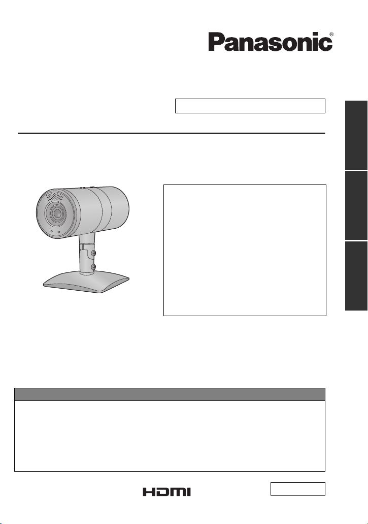
Operating Instructions <Basics>
Installation Instructions provided
HD Integrated Camera
Model No. AW-HE2P
AW-HE2E
≥ Die Bedienungsanleitung in Deutsch ist als
PDF-Datei in der CD-ROM enthalten. (l 2)
≥ Le mode d’emploi en français est fourni sous
forme de fichier PDF sur le CD-ROM. (l 2)
≥ Le istruzioni per l’uso in italiano sono
contenute in un file PDF sul CD-ROM. (l 2)
≥ Las instrucciones de funcionamiento en
español se encuentran en un archivo PDF
del CD-ROM. (l 2)
≥ Документ Инструкция по эксплуатации на
русском языке находится в виде PDFфайла на диске CD-ROM. (l 2)
Please read these instructions carefully before using this product, and save this manual for
future use.
How the Operating Instructions are configured
This <Basics> describes the procedure for basic operation and installation. Before
installing this unit, be sure to take the time to read through <Basics> to ensure that the unit
will be installed correctly.
For more detailed operating instructions, please refer to <Operations and Settings> (PDF
file) recorded on the attached CD-ROM.
≥ To open <Operations and Settings>, please refer to page 2.
≥ This <Basics> is also contained as a PDF file on the CD-ROM supplied with the unit.
Getting startedInstallation
Operating
Instructions
Instructions
F1012KY0 (2200 A)
Printed in Japan VQT4N15
ENGLISH
Page 2

ENGLISH
≥ How to open the operating instruction
manual PDF files
Discontinue installation if the installation
screen of the software opens as a result of
inserting the CD-ROM.
When [INDEX.pdf] on the CD-ROM is
opened, a list of the operating instruction
manuals will be displayed.
Click on the document name of the
manual to be opened.
≥ Adobe Reader is required to read PDF
files.
It can be downloaded from the home
page of Adobe Systems.
DEUTSCH
≥ Öffnen der PDF-Dateien der
Bedienungsanleitung
Brechen Sie die Installation ab, falls beim
Einlegen der CD-ROM der
Installationsbildschirm der Software
erscheint.
Wenn [INDEX.pdf] auf der CD-ROM
geöffnet wird, erscheint eine Liste der
Bedienungsanleitungen.
Klicken Sie auf den Dokumentennamen
der zu öffnenden Anleitung.
≥ Zum Lesen der PDF-Dateien benötigen
Sie Adobe Reader.
Dieses Programm kann von der
Homepage von Adobe Systems
heruntergeladen werden.
FRANÇAIS
≥ Comment ouvrir les fichiers PDF des
manuels du mode d’emploi
Arrêter l’installation si l’écran d’installation
du logiciel s’ouvre quand le CD-ROM est
inséré.
Quand [INDEX.pdf] sur le CD-ROM
s’ouvre, la liste des manuels du mode
d’emploi s’affiche.
Cliquer sur le nom du document
correspondant au manuel à consulter.
≥ Adobe Reader est nécessaire pour lire
les fichiers PDF.
Ce logiciel peut être téléchargé depuis
la page d’accueil d’Adobe Systems.
2
VQT4N15
ITALIANO
≥ Come aprire i file dei manuali di
istruzioni per l’uso
Se inserendo il CD-ROM si apre la
schermata di installazione del software,
interrompere l’installazione.
Aprendo [INDEX.pdf] sul CD-ROM, viene
visualizzato un elenco di manuali di
istruzioni per l’uso.
Fare clic sul nome del documento
corrispondente al manuale da aprire.
≥ Per leggere i file PDF è necessario
Adobe Reader.
Il programma può essere scaricato dal
sito Web di Adobe Systems.
ESPAÑOL
≥ Modo de abrir los archivos PDF que
contienen el manual de las
instrucciones de funcionamiento
Interrumpa la instalación si la pantalla de
instalación del software se abre como
resultado de insertar el CD-ROM.
Cuando se abra [
se visualizará una lista de los manuales de
instrucciones de funcionamiento.
Haga clic en el nombre de documento del
manual que va a abrir.
≥ Para leer los archivos PDF se necesita
el programa Adobe Reader.
Este programa se puede descargar de
la página inicial de Adobe Systems.
INDEX.pdf
] en el
CD-ROM
РУССКИЙ
≥ Как открыть PDF-файлы инструкции
по эксплуатации
Прекратите установку, если в результате
загрузки диска CD-ROM появилось окно
установки программного обеспечения.
При открытии файла [INDEX.pdf] на
диске CD-ROM будет отображен список
инструкций по эксплуатации.
Щелкните название документа
руководства, чтобы открыть его.
≥ Для чтения PDF-файлов потребуется
Adobe Reader.
Данное программное обеспечение
можно скачать с домашней страницы
Adobe Systems.
Page 3

Contents
Getting started
Read this first!........................................... 4
Accessories...............................................6
Optional accessories ........................... 7
Names and Functions of Main Parts .......8
Unit Configuration ............................... 8
Names and Functions of
Main Parts ........................................... 8
Mounting the Stand and
the Stand Cover ................................10
Tilting the Camera Up and Down ......10
Detaching and Attaching
the Rear Cover .................................. 11
Detaching and Attaching
the Middle Ring Portion ..................... 12
Starting the Web Setting Screen
(Live Screen/Setup Screen) .............. 40
Wireless remote controller .................... 44
Names and Functions of
Main Parts ......................................... 44
Usable Range for the Wireless
Remote Controller ............................. 45
Setting the Remote Control ID of
the Camera ....................................... 45
Before Operating With the Wireless
Remote Controller ............................. 46
About copyright...................................... 47
Specifications ......................................... 49
Getting startedInstallation
Installation Instructions
Information for Your Safety.................... 14
Installation precautions.......................... 15
How to connect and
install the unit.......................................... 18
Checking the installation location ...... 18
Preparing the power source .............. 19
Connecting the cables ......................19
Ceiling-suspended Installation ..........21
Standing Installation .......................... 22
Mount to a Tripod .............................. 23
Connection with Other Devices ............. 24
Connections with an HD monitor .......24
Connections with a controller
(AW-RP50, optional) ......................... 24
System example 1 (IP control) ..........25
System example 2 (IP control) ..........26
Operating Instructions
Information for Your Safety.................... 27
Characteristics........................................ 33
Cautions for use...................................... 35
Required personal computer
environment ............................................ 37
Network settings..................................... 38
Starting the Web Setting Screen ........... 40
VQT4N15
Instructions
Operating
Instructions
3
Page 4

Getting started
Read this first!
∫ References made in this manual
References made are as per below:
≥ Pages for reference are indicated by an arrow, for example: l 00
≥ AW-HS50 N, AW-HS50E # [AW-HS50]
≥ AW-RP50 N, AW-RP50E # [AW-RP50]
≥ Remote Camera Controller # [Controller]
∫ Regarding photos and illustrations in this manual
Please note that the product profile sketches, illustrations, menu screens, etc. in this manual
differ slightly from the actual product.
∫ Regarding personal computer screenshots
Descriptions are provided using screenshots from Windows 7.
∫ To prevent unauthorized use
≥ Your user name and password on the web setting screen.
jDo not use the default user name and password. Make sure you change them.
jDo not set the same character string for the user name and password.
jDo not allow anyone else to see the user name and password, and do not tell them to
anyone else.
jIn the case that a third party sets up/performs settings for the unit, be sure to change the
user name and password after the third party has done so.
jWhen requesting repairs, restore the default settings with the INIT button (l 9), and then
reset your user name and password.
(When the default settings are restored, the default network settings are also restored.
Please make a note of the network settings, user name, and password.)
≥ Set a screensaver protected with a password for the personal computer.
∫ Precautions when requesting repairs
Take note of each setting you have changed in the camera when requesting repairs. Your
current settings may be deleted or modified.
∫ When disposing of/transferring the unit
The unit records personal information related to your operations. When you part with the unit
due to such reasons as disposal or transfer, make sure to restore the default settings with the
INIT button (l 9) and erase recorded information.
∫ Privacy and Image Rights
Set up and use the camera at your own responsibility. Take into consideration subjects’
privacy (including sounds picked up by the microphone), portrait rights, and the like first.
4
VQT4N15
Page 5

∫ Disclaimer of warranty
IN NO EVENT SHALL Panasonic Corporation BE LIABLE TO ANY PARTY OR ANY
PERSON, EXCEPT FOR REPLACEMENT OR REASONABLE MAINTENANCE OF THE
PRODUCT, FOR THE CASES, INCLUDING BUT NOT LIMITED TO BELOW:
1) ANY DAMAGE AND LOSS, INCLUDING WITHOUT LIMITATION, DIRECT OR
INDIRECT, SPECIAL, CONSEQUENTIAL OR EXEMPLARY, ARISING OUT OF OR
RELATING TO THE PRODUCT;
2) PERSONAL INJURY OR ANY DAMAGE CAUSED BY INAPPROPRIATE USE OR
NEGLIGENT OPERATION OF THE USER;
3) UNAUTHORIZED DISASSEMBLE, REPAIR OR MODIFICATION OF THE PRODUCT
BY THE USER;
4) INCONVENIENCE OR ANY LOSS ARISING WHEN IMAGES ARE NOT DISPLAYED,
DUE TO ANY REASON OR CAUSE INCLUDING ANY FAILURE OR PROBLEM OF
THE PRODUCT;
5) ANY PROBLEM, CONSEQUENTIAL INCONVENIENCE, OR LOSS OR DAMAGE,
ARISING OUT OF THE SYSTEM COMBINED BY THE DEVICES OF THIRD PARTY;
6) LOSS OF REGISTERED DATA CAUSED BY ANY FAILURE.
∫ Network security
As you will use this unit connected to a network, your attention is called to the following
security risks.
1) Leakage or theft of information through this unit
2) Use of this unit for illegal operations by persons with malicious intent
3) Interference with or stoppage of this unit by persons with malicious intent
It is your responsibility to take precautions such as those described below to protect yourself
against the above network security risks.
≥ Use this unit in a network secured by a firewall, etc.
≥ If this unit is connected to a network that includes personal computers, make sure that the
system is not infected by computer viruses or other malicious entities (using a regularly
updated antivirus program, anti-spyware program, etc.).
≥ Protect your network against unauthorized access by restricting users to those who log in
with an authorized user name and password.
≥ Take measures by authenticating the users of the unit in order to restrict access, for
example, so that the setting information contained inside the unit is not leaked over the
network.
≥ Do not install the camera in locations where the camera or the cables can be destroyed or
damaged by persons with malicious intent.
≥ Refrain from connections that use public lines.
Usage restrictions
Use of the same segment is recommended for the network in which the unit and the
controller or personal computer are connected.
If the equipment uses connections with different segments, events based on the settings
inherent to the network equipment, for instance, may occur so check this thoroughly prior to
operation.
VQT4N15
5
Page 6
Getting started
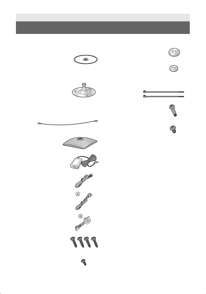
Accessories
Check the accessories before using this unit.
CD-ROM
≥ Operating Instructions
(<Basics>, <Operations
and Settings>)
≥ Easy IP Setup Software
(EasyIpSetup.exe)
Stand
Remove the stand
protrusion, stand fixing
screw
and spring washer
when using a tripod. (l 23)
Drop-prevention wire
Stand cover
AC adaptor
AC cable
for AW-HE2P
Flat washer (for M4
screw)
Flat washer (for M3
screw)
Bundling band
(2 bands)
Perpendicular fixing
screw
(installed on the unit)
Horizontal fixing screw
(installed on the unit)
≥ Refer to page 10 concerning the mounting
method for the stand and stand cover.
≥ Keep the screws, washers, bundling
bands, drop-prevention wire and stand
protrusion out of reach of children to
prevent swallowing.
AC cable
for AW-HE2E
for AW-HE2E
≥ In Saudi Arabia, always
use
B.
M4 screw
20 mm (0.787 q) length
(4 screws)
M3 screw
8 mm (0.315 q) length
6
VQT4N15
Page 7

Optional accessories
The following optional product is compatible with the unit:
Some optional accessories may not be available in some countries.
Product name (product number)
≥ Wireless remote controller (AW-RM50G)
≥ Remote Camera Controller (AW-RP50N, AW-RP50E)
≥ USB cable (K2KYYYY00221)
(contact a sales store for information about purchases)
Product numbers correct as of Oct. 2012. These may be subject to change.
VQT4N15
7
Page 8
Getting started
2
3
4
5
1
6
7
8
9
10
Names and Functions of Main Parts
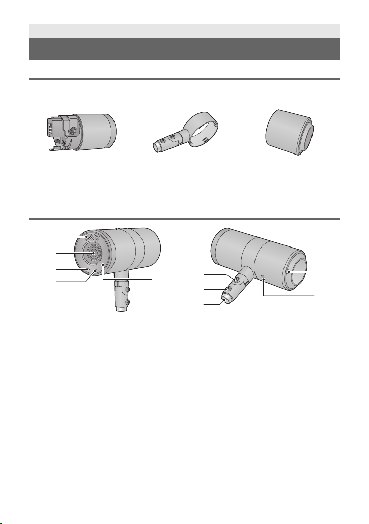
Unit Configuration
This unit consists of the camera body, middle ring portion and rear cover.
Camera body Middle ring portion Rear cover
≥ Detaching and attaching the Rear Cover (l 11 )
≥ Detaching and attaching the Middle Ring Portion (l 12)
≥ The middle ring portion has a front and rear orientation. Take note of the front and rear
orientation when attaching the middle ring portion or passing cables through.
Names and Functions of Main Parts
(l 12, 20)
1 Internal stereo microphones
2Lens
3 Status display lamp
jOrange light: Standby mode
jGreen light: The unit is turned on
jFlashing green light:
The unit is receiving a wireless remote
control signal with a matching remote
control ID
jFlashing orange light:
The unit is receiving a wireless remote
control signal with a different remote
control ID
4 Tally lamp
5 Wireless remote control signal
light-sensing area (l 45)
6 Perpendicular fixing screw (l 10)
7 Horizontal fixing screw (l 10, 23)
8
VQT4N15
8 Stand mounting hole (l 10, 23)
9 Bundling band eyelet (l 20)
10 Anti-theft wire mounting hole (l 20)
The anti-theft wire (available from a
hardware store) is attached here.
Page 9

∫ When the rear cover is detached
11
12
13
14
15
16
17
18
19
20
11 RELEASE lever (l 12)
12 USB terminal [ ](l 20)
Power can be supplied from any device that
complies with USB battery charging
standards, including Micro USB AC/DC
converters for ordinary cell phones, personal
computers, or televisions. When doing so,
use the USB cable.
≥ Always use a genuine Panasonic USB
cable (K2KYYYY00221: optional).
13 HDMI terminal (l 20)
14 Drop-prevention wire mounting
portion (l 20)
15 LAN connector (l 20)
Use a category 5 or above LAN cable with a
maximum length of 100 m (328 ft.).
16 LAN lamp [LINK/ACT]
Lights up when data is transmitted/received
via LAN.
17 microSD card slot
This portion is used when updating the
firmware of the unit. (Not ordinarily used)
≥ Keep the microSD card out of reach of
children to prevent swallowing.
∫ When the middle ring portion is detached
18 INIT button
If you press the button while the unit is
turned on, the user management settings
and the network settings are initialized.
Initialize using the following procedure.
1) Close the camera menu and the web
settings screen.
2) Press the INIT button.
3) Switch on the power again using the
power button.
19 Power button [ ]
If you press the button when the unit is in
standby mode or turned off, the unit is turned
on. If you press and hold the button when
the unit is in standby mode or turned on, the
unit is turned off.
20 DC input terminal [DC IN] (l 20)
≥ Do not use any other AC adaptors except
the supplied one.
VQT4N15
9
Page 10
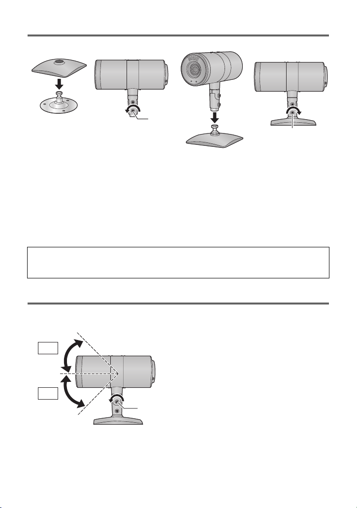
Mounting the Stand and the Stand Cover
45°
45°
1 (only when using the stand cover)
Put the stand cover on the stand.
2 Loosen the horizontal fixing screw A.
3 Insert the stand in the stand mounting hole.
4 Tighten the horizontal fixing screw A.
≥ Tightening torque: 1.176 N·m (12 kgf·cm)
≥ Tighten it firmly so that there is no wobbling.
When the horizontal fixing screw is loosened, the camera can be rotated 360° in the
horizontal direction.
Adjust the position of the camera to suit the installation location.
Tilting the Camera Up and Down
When the perpendicular fixing screw A is loosened, the camera can be tilted approximately
45°up or down.
≥ After adjusting the position of the camera, firmly tighten the screw to fix the camera in
10
VQT4N15
position.
(Tightening torque: 1.176 N·m (12 k
gf·cm))
Page 11
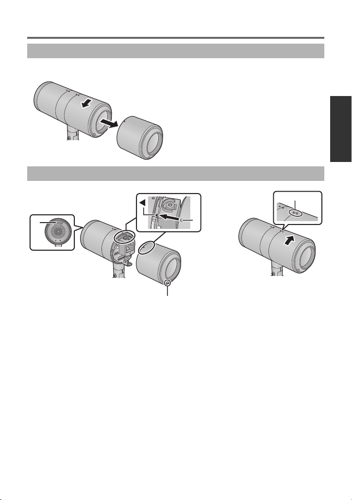
Detaching and Attaching the Rear Cover
Detaching the Rear Cover
Turn the rear cover in the direction of the arrow and detach it.
Attaching the Rear Cover
1 Align the mark 2 on the camera body with the mark A on the rear
cover and insert it.
≥ Attach the rear cover with the internal stereo microphones B facing up, and the bundling
band eyelet c facing down (the cover cannot be attached in the reverse order).
2 Attach the rear cover by turning it in the direction of the arrow.
≥ Align the middle ring portion and the mark D on the rear cover.
11
VQT4N15
Page 12
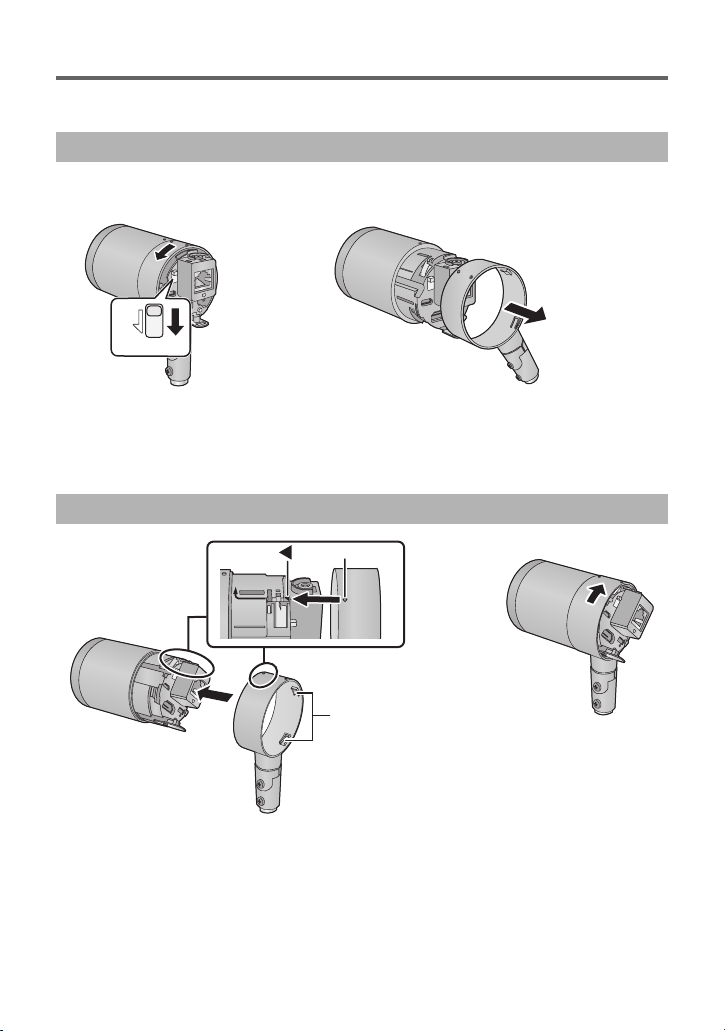
Detaching and Attaching the Middle Ring Portion
RELEASE
Detach the middle ring portion when connecting the AC adaptor or when installing the middle
ring portion upside down by suspending the camera from the ceiling.
Detaching the middle ring portion
≥ Detach the rear cover (l 11)
1 While sliding the RELEASE lever, turn the middle ring portion in the
direction of the arrow.
2 Pull the middle ring portion out from the camera body.
Mounting the middle ring portion
1 Insert the middle ring portion in the camera body.
≥ Insert the middle ring portion from the opposite side of the groove (A) into the camera
body.
≥ Align the mark B on the middle ring portion with the 2 mark on the camera body and
insert it.
12
VQT4N15
Page 13
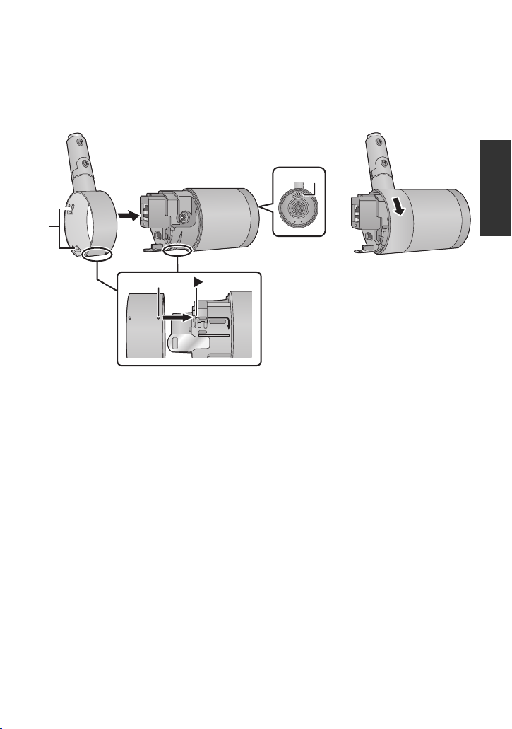
2 Turn the middle ring portion in the direction of the arrow to attach
the middle ring portion to the camera body.
≥ Turn it until there is a clicking noise and it locks into place.
∫ For ceiling-suspended installation
Mount the middle ring portion to the camera body while moving it up/down or rotating it.
1 Insert the middle ring portion in the camera body.
≥ Check which portions of the camera body are the top and bottom by looking at the
positions of the internal stereo microphones A.
≥ Insert the middle ring portion from the opposite side of the groove (B) into the camera
body.
≥ Align the mark C on the middle ring portion with the
insert it.
1
mark on the camera body and
2 Turn the middle ring portion in the direction of the arrow to attach
the middle ring portion to the camera body.
≥ Turn it until there is a clicking noise and it locks into place.
13
VQT4N15
Page 14

Installation Instructions
Information for Your Safety
WARNING:
To prevent injury, this apparatus must be securely attached to the floor/wall/ceiling in
accordance with the installation instructions.
WARNING:
Installation should only be performed by qualified installation personnel.
Improper installation may result in the entire apparatus falling down and causing injury.
14
VQT4N15
Page 15

Installation Instructions
Installation precautions
Panasonic does not accept any responsibility for accident or damage during installation if
procedure in this manual is not followed.
To installation personnel
Read the “Installation Instructions” thoroughly and then perform the operation correctly and
safely.
Also, always read the “Information for Your Safety” (l 14) of this manual as they contain
important information.
After the installation, give the “Operating Instructions <Basics>” to the customer to save for
future use.
Ensure that the installation work complies with the technical standards governing
electrical equipment.
This unit is for indoor use only.
It cannot be used outdoors.
Avoid installation in a location where the unit will be exposed to direct sunlight for extended
periods or near a cooling or heating appliance.
Otherwise, deformation, discoloration, malfunctioning and/or problems in operation may
result. Operate the unit where it will not be splashed or sprayed by water.
Use the unit with an installation where the unit is suspended from an overhead surface
or with a stand-alone installation.
Do not use the unit on its side.
≥ When using screws to fix parts during installation, be sure to use the supplied screws.
Do not use wood screws, nails, etc.
In the case of a concrete ceiling, secure the unit using anchor bolts (for M4) or AY plug
bolts (for M4).
Tightening torque: 1.176 N·m (12 k
≥ Installation conditions (ceiling-suspended installation/standing installation)
jCamera weight: 244
rear cover)
jMinimum pulling strength (per screw): 147 N (15 k
jNo. of screws: 3 screws
g (including stand, stand cover, middle ring portion and
gf·cm )
gf)
Concerning the installation location
Install the unit in a stable location which will not be susceptible to shaking. If the unit is
installed in a location which is susceptible to shaking, this will cause the unit’s images to
shake in turn.
Install the unit after conferring in detail with your dealer.
Install the unit on a ceiling that is strong enough (such as a concrete ceiling).
If the unit is to be installed on a ceiling which is not strong enough, reinforce the ceiling
sufficiently first.
VQT4N15
15
Page 16

Do not install or use the unit in the following kinds of locations.
≥ On walls (where the unit would be installed sideways)
≥ In locations (including places such as under the eaves of a building) where the unit would
be directly exposed to rain or water
≥ In locations such as kitchens where there are high concentrations of steam and grease
≥ In outdoor locations or hot places where the temperature will exceed 40 oC (104 °F)
≥ In cold locations where the temperature will drop below 0 oC (32 °F)
≥ In locations where the humidity will exceed 80%RH
≥ In locations where chemicals are used such as near swimming pools
≥ At sea, in coastal areas or in locations where corrosive gases are emitted
≥ In locations where radiation, X-rays, or strong radio waves or magnetic fields are
generated
≥ In locations where the unit would be subject to a great deal of vibration such as on board a
vehicle or ship (this unit is not designed to be used in vehicles)
≥ In locations where the temperature is subject to sudden changes such as near the air
outlet of an air conditioner or near a door which allows the outside air to come in
What to avoid to ensure that the unit will perform stably over a prolonged period.
≥ Using the unit for a prolonged period in a location with high temperature and humidity
levels will cause its parts to deteriorate and shorten its service life.
≥ Ensure that a cooling unit or heating unit will not blow any air directly toward the installation
location.
Be absolutely sure to use the supplied stand and screws to install the camera.
≥ Do not mount the unit by employing any methods other than those specified.
≥ Do not remodel the stand or screws provided with the unit.
Before installation, always disconnect the power plug.
Tightening up the mounting screws
≥ Tighten up the screws and bolts securely to the degree that is appropriate for each of the
materials used in the mounting location and structures.
≥ After tightening up the screws and bolts, check that there is no unsteadiness and that the
parts have been tightened securely.
≥ Use the specified tools and tighten the screws firmly.
≥ Tighten up the screws using the specified torque driver. Do not use electrical drivers or
impact drivers.
When the unit is no longer going to be used, do not leave it lying around, but be
absolutely sure to dispose of it properly.
Do not attach a filter, hood, extender or other parts to the unit.
Use the dedicated AC adaptor and AC cable provided with the unit.
Connect the AC adaptor and AC cable to the power inlet securely.
Installing the AC adaptor
≥ Do not place the AC adaptor directly onto a ceiling panel or other such surface.
Extreme danger is posed when water has collected on the surface as a result of leaking
rain, for instance.
Secure the AC adaptor firmly to the bottom or other surface of a reinforcing member made
of channel steel where dust will not accumulate.
16
VQT4N15
Page 17

≥ Secure the AC adaptor firmly so that there will be no chance that it will fall off or fall down.
Secure it using a strength which can withstand the mass (approx. 0.1 k
AC adaptor.
Install the accessory AC adaptor near the main power outlet, and position it in such a
way that its power plug can be plugged into and unplugged from the outlet easily.
When connecting the AC adaptor to a power outlet on the ceiling or on any other surface
where dust may collect, wipe off the dust on the power plug at periodic intervals as an
anti-tracking measure.
Connecting the AC cable
Be absolutely sure to connect the AC cable of the AC adaptor through a circuit breaker using
one of the following methods.
1) Connect the power cable through a power control unit.
2) Connect the power cable to a circuit breaker in a power distribution panel with a contact
distance of 3.0 mm or more. Use a circuit breaker which is capable of shutting off all the
poles of the main power supply with the exception of the protective ground conductor.
3) Install the AC adaptor near the power outlet, and connect it through the power plug.
If there is a possibility of noise interference
Either wire the cables so that the power cable (ceiling light cord) of AC 100 V* (AC 220 V**)
or more, and the signal cable are placed at least 1 m (3.3 ft.) apart.
Alternatively run each cable through its own metal conduit.
(The metal conduits must be grounded.)
Radio signal interference
If the unit is positioned near a TV or radio transmitting antenna or a strong electrical field or
magnetic field (such as that generated by a motor, transformer or power lines), its images
may be distorted and/or the images may be affected by noise.
When connecting the cables, ensure that the connector areas will not be subject to
any load.
Doing so may cause malfunctioning.
Allowing the generated heat to escape
This unit allows the heat generated inside to escape from its surfaces.
Do not install the unit in a location where it will be surrounded by walls or other surfaces and
where heat will be trapped.
g (0.22 lb.)) of the
*For AW-HE2P
**For AW-HE2E
17
VQT4N15
Page 18

Installation Instructions
118
(4.646
)
80 (3.15
)
55 (2.165
)
80 (3.15
)
30
(1.181
)
38 (1.496
)
70 (2.756
)
29 (1.142
)
54 (2.126
)
40 (1.575
)
138 (5.433
)
How to connect and install the unit
Be absolutely sure to read through the “Information for Your Safety” (l 14) and “Installation
precautions” (l 15 to 17).
Connect and install in the following order:
1) Checking the installation location
2) Preparing the power source
3) Connecting the cables
4) Ceiling-suspended Installation/Standing Installation/Mount to a Tripod
Checking the installation location
Refer to the illustration, and determine where the unit is to be installed and in which direction
it should be mounted.
≥ Ensure that there is at least 200 mm (7.874 q) of space for wiring behind the rear cover.
Unit: mm (inch)
18
VQT4N15
Page 19

Preparing the power source
Connect the AC cable to the AC adaptor and the socket.
≥ Use the supplied AC adaptor. Do not use the AC adaptor of another device.
≥ Do not use the AC cable with any other equipment as it is designed only for this unit.
Also, do not use the AC cable from other equipment with this unit.
≥ Concerning the socket used on the ceiling, be sure to take preventative measures
against tracking caused by dust and the like.
≥ The camera can also be used by connecting a USB cable. (l 9)
Connecting the cables
≥ When installing the unit on a ceiling, connect the LAN cable, the HDMI cable, the AC
adaptor cable, the USB cable, and the anti-theft wire in the space above the ceiling
panel, and draw each cable out from the cable eyelet.
≥ Please use “High Speed HDMI Cables” that have the HDMI logo (as shown on the
cover). Cables not conforming to the HDMI standard will not work. Panasonic HDMI
cable is recommended.
Part No.: RP-CDHS15 (1.5 m (4.9 ft.)), RP-CDHS30 (3.0 m (9.8 ft.))
≥ Always use a genuine Panasonic USB cable (K2KYYYY00221: optional).
1 Detach the rear cover and the middle ring portion. (l 11, 12)
19
VQT4N15
Page 20

2 Pass each cable through the rear cover and the middle ring portion
LAN
and connect them to the rear of the camera body.
≥ Pass cables from the side with the middle ring portion groove (A).
A
B M3 screw (supplied)
Tightening torque: 0.882 N·m (9 k
C Flat washer (for M3 screw, supplied)
D Drop-prevention wire (supplied)
E AC adaptor (supplied)
F LAN cable (l 9)
G HDMI cable (optional)
H USB cable (optional)
≥ Connect this when supplying power from the USB cable.
≥ Insert with the mark on the cable facing upwards.
gf·cm)
3 Attach the middle ring portion and the rear cover. (l 11, 12)
Check that the top and bottom of the middle ring portion are in a position which
suits the installation method. (l 13)
4 Connect the anti-theft wire.
≥ As necessary for use, pass the bundling band through the bundling band eyelet and bind
the cables together.
20
VQT4N15
Page 21

Ceiling-suspended Installation
When installing the camera by suspending it from the ceiling, be sure to attach the
drop-prevention wire.
1 Mount the stand to the ceiling using the M4
screws (supplied).
≥ Tightening torque: 1.176 N·m (12 kgf·cm)
≥ Screw the stand’s three holes.
≥ Do not use any screws other than those supplied with the unit (do
not use wood screws, nails, etc.).
≥ Make sure the stand is firmly mounted to the ceiling, with no tilting
or wobbling.
≥ Screw the drop-prevention wire separately to the stand.
2 Mount the drop-prevention wire to the ceiling
by using the M4 screw (supplied) and the flat
washer (for M4 screw, supplied).
≥ Tightening torque: 1.176 N·m (12 kgf·cm)
≥ Pull the drop-prevention wire, and check that it has been
attached securely.
≥ The drop-prevention wire is designed to be used for installation where the unit is
suspended from an overhead surface so do not subject it to the weight of units other than
the unit.
21
VQT4N15
Page 22

3 Fix the camera to the stand.
1) Put the stand cover on the middle ring portion.
2) Loosen the horizontal fixing screw and insert the stand into the stand mounting hole.
3) Tighten the horizontal fixing screw and fix the camera to the stand.
≥ Tightening torque: 1.176 N·m (12 k
≥ Attach the camera securely with a prescribed tool.
≥ Adjust the horizontal orientation of the camera before fixing.
≥ Tilt the camera horizontally and vertically as necessary for use. (l 10)
Standing Installation
Mount the stand/stand cover to the camera and install it. (l 10)
≥ If you want to fix the stand, screw the stand to the
installation surface with the M4 screws (supplied), and then
mount the stand cover and the camera to the stand.
jTightening torque: 1.176 N·m (12 k
≥ Place the unit such that it is horizontal to the installation surface.
≥ Install the unit in a stable location where there is no vibration.
Vibration of the installation location causes image vibration.
≥ When installing the camera, take care that it does not fall, etc.
≥ Take care that the connected cables do not catch on something.
If they do it may cause a fall or injury.
gf·cm)
gf·cm)
22
VQT4N15
Page 23

Mount to a Tripod
The tripod mounting hole of the unit supports 1/4-20UNC.
≥ Loosen the horizontal fixing screw (l 10)
1 Remove the stand fixing
screw A and spring washer
B, and detach the stand
protruding portion C.
jThe stand protruding portion can be
used as a tripod mounting hole.
2 Insert the stand protruding portion in the
stand mounting hole, and tighten the
horizontal fixing screw.
≥ Tightening torque: 1.176 N·m (12 kgf·cm)
3 Mount a tripod to the tripod mounting hole D.
≥ Place the tripod on a completely flat and level surface.
≥ Tighten the screws by hand to mount the tripod securely.
≥ Do not install the unit where people will be passing back
and forth.
≥ When using the unit mounted on a tripod, do not put the
tripod high above the floor level.
≥ Mount the unit securely so there is no looseness.
Looseness may cause the unit to fall off and/or result in
injuries.
≥ When the unit is going to be used for a prolonged period
of time, take steps to ensure that the unit will not topple or
fall over and that it will not fall off or fall down. After using the unit, restore the installation
location to its original state without delay.
∫ To return the stand to the condition it was in when you purchased it,
Use the stand fixing screw and spring washer to screw the stand protrusion to the stand.
≥ Align the stand protruding portion and the stand correctly so that the stand protruding
portion does not turn.
≥ Tightening torque: 2.94 N·m (30 k
gf·cm)
23
VQT4N15
Page 24

Installation Instructions
Connection with Other Devices
≥ Connect the AC adaptor supplied with the unit, controller (AW-RP50) and compact live
switcher (AW-HS50) to each device.
≥ Please use “High Speed HDMI Cables” that have the HDMI logo (as shown on the cover).
Cables not conforming to the HDMI standard will not work. Panasonic HDMI cable is
recommended.
Part No.: RP-CDHS15 (1.5 m (4.9 ft.)), RP-CDHS30 (3.0 m (9.8 ft.))
≥ The unit is capable of transmitting IP images to only one terminal.
≥ If the unit is simultaneously controlled by more than one controller (AW-RP50), the unit
may not function correctly.
Connections with an HD monitor
A HDMI cable:
An HDMI video/audio signal is output.
B Wireless remote controller (optional)
Connections with a controller (AW-RP50, optional)
A HDMI cable:
An HDMI video/audio signal is output.
B LAN cable:
A camera control sign is output.
C Controller (AW-RP50)
24
VQT4N15
Page 25

System example 1 (IP control)
: HDMI cable
: LAN cable
: Use an appropriate cable to suit the connected devices.
A HDMI/SDI converter
B Compact Live Switcher (AW-HS50)
C Personal computer
D Switching hub
E Monitor 1/Monitor 2
F Controller (AW-RP50)
25
VQT4N15
Page 26

System example 2 (IP control)
: HDMI cable
: LAN cable
: Use an appropriate cable to suit the connected devices.
A Switcher
B Personal computer
C Switching hub
D Monitor 1/Monitor 2
E Controller (AW-RP50)
26
VQT4N15
Page 27

Operating Instructions
Information for Your Safety
For AW-HE2P
WARNING:
To reduce the risk of fire, electric shock or product damage,
≥ Do not expose this unit to rain, moisture, dripping or splashing.
≥ Do not place objects filled with liquids, such as vases, on this unit.
≥ Use only the recommended accessories.
≥ Do not remove covers.
≥ Do not repair this unit by yourself. Refer servicing to qualified service personnel.
CAUTION!
To reduce the risk of fire, electric shock or product damage,
≥ Do not install or place this unit in a bookcase, built-in cabinet or in another confined
space. Ensure this unit is well ventilated.
≥ Do not obstruct this unit’s ventilation openings with newspapers, tablecloths, curtains, and
similar items.
≥ Do not place sources of naked flames, such as lighted candles, on this unit.
CAUTION:
Check the installation at least once a year.
An improper installation could cause the unit to fall off resulting in personal injury.
CAUTION:
Do not pick up and move the unit while the tripod is attached.
The fitting may break under the weight of the tripod, which may result in injury.
∫ Product identification marking
Product Location
HD Integrated Camera Bottom
AC adaptor Bottom
Install this unit so that the power cord can be unplugged from the socket outlet immediately
if any problem occurs.
VQT4N15
27
Page 28

THE FOLLOWING APPLIES ONLY IN THE U.S.A. AND CANADA.
AC adaptor
This AC adaptor operates on AC between 100 V and 240 V.
But
≥ In the U.S.A. and Canada, the AC adaptor must be connected to a 120 V AC power
supply only.
≥ When connecting to an AC supply outside of the U.S.A. or Canada, use a plug adaptor to
suit the AC outlet configuration.
≥ When connecting to a supply of greater than AC 125 V, ensure the cord you use is suited
to the voltage of the AC supply and the rated current of the AC adaptor.
≥ Contact an electrical parts distributor for assistance in selecting a suitable AC plug
adaptor or AC cord set.
Conforms to UL STD 60065
28
VQT4N15
Page 29

FCC NOTICE (USA)
AW-HE2P
Declaration of Conformity
Model Number: AW-HE2P
Trade Name: Panasonic
Responsible Party: Panasonic Corporation of North America
One Panasonic Way, Secaucus, NJ 07094
Support contact: 1-800-524-1448
This device complies with Part 15 of the FCC Rules.
Operation is subject to the following two conditions:
(1) This device may not cause harmful interference, and (2) this device must accept any
interference received, including interference that may cause undesired operation.
To assure continued compliance, follow the attached installation instructions and do not
make any unauthorized modifications.
CAUTION:
This equipment has been tested and found to comply with the limits for a Class B digital
device, pursuant to Part 15 of the FCC Rules. These limits are designed to provide
reasonable protection against harmful interference in a residential installation. This
equipment generates, uses and can radiate radio frequency energy and, if not installed
and used in accordance with the instructions, may cause harmful interference to radio
communications. However, there is no guarantee that interference will not occur in a
particular installation. If this equipment does cause harmful interference to radio or
television reception, which can be determined by turning the equipment off and on, the
user is encouraged to try to correct the interference by one of the following measures:
≥ Reorient or relocate the receiving antenna.
≥ Increase the separation between the equipment and receiver.
≥ Connect the equipment into an outlet on a circuit different from that to which the
receiver is connected.
≥ Consult the dealer or an experienced radio/TV technician for help.
The user may find the booklet “Something About Interference”
available from FCC local regional offices helpful.
FCC Warning:
To assure continued FCC emission limit compliance, follow the attached installation
instructions and the user must use only shielded interface cables with ferrite core when
connecting to host computer or peripheral devices. Also, any unauthorized changes or
modifications to this equipment could void the user’s authority to operate this device.
NOTIFICATION (Canada)
This Class B digital apparatus complies with Canadian ICES-003.
indicates safety information.
THE FOLLOWING APPLIES ONLY IN THE U.S.A.
29
VQT4N15
Page 30

IMPORTANT SAFETY INSTRUCTIONS
Read these operating instructions carefully before using the unit. Follow the safety
instructions on the unit and the applicable safety instructions listed below. Keep these
operating instructions handy for future reference.
1) Read these instructions.
2) Keep these instructions.
3) Heed all warnings.
4) Follow all instructions.
5) Do not use this apparatus near water.
6) Clean only with dry cloth.
7) Do not block any ventilation openings.
Install in accordance with the
manufacturer’s instructions.
8) Do not install near any heat sources
such as radiators, heat registers,
stoves, or other apparatus (including
amplifiers) that produce heat.
9) Do not defeat the safety purpose of the
polarized or grounding-type plug. A
polarized plug has two blades with one
wider than the other. A grounding-type
plug has two blades and a third
grounding prong. The wide blade or the
third prong are provided for your safety.
If the provided plug does not fit into your
outlet, consult an electrician for
replacement of the obsolete outlet.
12) Use only with the
cart, stand, tripod,
bracket, or table
specified by the
manufacturer, or
sold with the
apparatus. When a
cart is used, use caution when moving
the cart/apparatus combination to avoid
injury from tip-over.
13) Unplug this apparatus during lightning
storms or when unused for long periods
of time.
14) Refer all servicing to qualified service
personnel. Servicing is required when
the apparatus has been damaged in any
way, such as power-supply cord or plug
is damaged, liquid has been spilled or
objects have fallen into the apparatus,
the apparatus has been exposed to rain
or moisture, does not operate normally,
or has been dropped.
10) Protect the power cord from being
walked on or pinched particularly at
plugs, convenience receptacles, and the
point where they exit from the
apparatus.
11) Only use attachments/accessories
specified by the manufacturer.
30
VQT4N15
Page 31

For AW-HE2E
WARNING:
To reduce the risk of fire, electric shock or product damage,
≥ Do not expose this unit to rain, moisture, dripping or splashing.
≥ Do not place objects filled with liquids, such as vases, on this unit.
≥ Use only the recommended accessories.
≥ Do not remove covers.
≥ Do not repair this unit by yourself. Refer servicing to qualified service personnel.
CAUTION!
To reduce the risk of fire, electric shock or product damage,
≥ Do not install or place this unit in a bookcase, built-in cabinet or in another confined
space. Ensure this unit is well ventilated.
≥ Do not obstruct this unit’s ventilation openings with newspapers, tablecloths, curtains, and
similar items.
≥ Do not place sources of naked flames, such as lighted candles, on this unit.
CAUTION:
Check the installation at least once a year.
An improper installation could cause the unit to fall off resulting in personal injury.
CAUTION:
Do not pick up and move the unit while the tripod is attached.
The fitting may break under the weight of the tripod, which may result in injury.
∫ Product identification marking
Product Location
HD Integrated Camera Bottom
AC adaptor Bottom
Install this unit so that the AC mains lead can be unplugged from the socket outlet
immediately if any problem occurs.
AEEE Yönetmeliğine Uygundur.
AEEE Complies with Directive of Turkey.
For Europe
∫ EMC Electric and magnetic compatibility
This symbol (CE) is located on the rating plate.
31
VQT4N15
Page 32

For the United Kingdom customers
∫ Caution for AC mains lead
For your safety, please read the following text carefully.
This appliance is supplied with a moulded three pin mains plug for your safety and
convenience. A 5-ampere fuse is fitted in this plug.
Should the fuse need to be replaced please ensure that the replacement fuse has a rating of
5-ampere and that it is approved by ASTA or BSI to BS1362.
Check for the ASTA mark Ï or the BSI mark Ì on the body of the fuse.
If the plug contains a removable fuse cover you must ensure that it is refitted when the fuse is
replaced.
If you lose the fuse cover the plug must not be used until a replacement cover is obtained.
A replacement fuse cover can be purchased from your local dealer.
∫ Before use
Remove the connector cover.
∫ How to replace the fuse
The location of the fuse differ according to the type of AC mains plug (figures A and B).
Confirm the AC mains plug fitted and follow the instructions below.
Illustrations may differ from actual AC mains plug.
1. Open the fuse cover with a screwdriver.
2. Replace the fuse and close or attach the fuse cover.
32
VQT4N15
Page 33

Operating Instructions
Characteristics
∫ Overview
≥ This HD camera features single focus, ultra-wide angle 95° lens, and uses a 1/2.33 type
(1/2.33z)* HD MOS sensor and digital signal processor (DSP).
* The effective size of the MOS sensor is 1/4.37.
≥ When preset memory is used, digital pan/tilt/zoom functions mean users can flip through
images in an instant to shoot quietly.
≥ By connecting a controller, the camera operations can be performed smoothly by IP
control.
≥ By connecting the unit to a personal computer through an IP network, it is possible to
operate the unit from the Web browser screen.
∫ Characteristics
Multiple number of formats supported
≥ HDMI signals can be output in 1080/59.94p, 1080/50p, 1080/59.94i, 1080/50i, 720/59.94p,
720/50p, 480/59.94p, and 576/50p formats.
≥ With the SD format, either Squeeze, LetterBox or SideCut can be selected.
≥ LAN signals will be output at 640x360/30p, 320x180/30p. This signal can be used for
monitors.
Uses a 1/2.33 type (1/2.33z) MOS sensor and ultra-wide angle 95° single focus lens
≥ Equipped with Dynamic Range Stretch (DRS) for correcting blown-out highlights and
blocked-up shadows, this unit can recreate clear images for a wide range of uses.
≥ Storage of up to 9 positions in the preset memory (The number of preset memories that
can be used varies from one controller to another.)
≥ Equipped with the PinP function to enable the main screen and sub screen to be
controlled and displayed individually.
High degree of compatibility with Panasonic’s currently available controllers, enabling
a flexible system to be put together
≥ Can be used with other current cameras from Panasonic to put together a flexible system
based on existing systems.
jIt may be necessary to upgrade the version of the controller in order to support the unit.
Use of easy-to-operate wireless remote controller (optional) is possible
≥ A wireless remote controller capable of operating up to four units can be used.
It can easily be used to set the various functions or switch between them while viewing the
menu screens.
Flexible camera layout enabled by simple connection and installation
≥ IP control, lightweight body and simple up/down and inverse mechanism result in
outstanding DIY (indoor applications only) connectivity and installation ease.
jBear in mind that this unit is designed to be used indoors only: It cannot be used
outdoors.
33
VQT4N15
Page 34

Energy-savings achieved by the compact main unit design
≥ The main unit is lightweight and compact at less than 244
consumption means multiple cameras can be connected easily.
Easy connections and settings courtesy of IP control
≥ Up to a hundred units can be operated by IP connection from a Panasonic controller
(AW-RP50). (The maximum length of the LAN cables is 100 m (328 ft.).)
g, and a low 3.6 W energy
34
VQT4N15
Page 35

Operating Instructions
Cautions for use
Shoot under the proper lighting conditions.
To produce pictures with eye-pleasing colors, shoot under the proper lighting conditions.
The pictures may not appear with their proper colors when shooting under fluorescent lights.
Select the proper lighting as required.
To ensure a stable performance in the long term
Using the unit for prolonged periods in locations where the temperature and humidity levels
are high will cause its parts to deteriorate, resulting in a reduction of its service life.
(Recommended temperature: Max. 35 oC (95 °F))
Ensure that a cooling unit or heating unit will not blow any air directly toward the installation
location.
Do not point the camera at strong lights.
When parts of the MOS sensor are exposed to spotlights or other strong lights, blooming (a
phenomenon where the edges of strong lights become blurred) may occur.
What happens with high-brightness subjects
Flare may occur if an extremely bright light source is pointed at the lens. In a case like this,
change the angle or take some other remedial action.
Operating temperature range
Avoid using the unit in cold locations where the temperature drops below 0 oC (32 °F) or hot
locations where the temperature rises above 40 oC (104 °F) since these temperatures
downgrade the picture quality and adversely affect the internal parts.
Also, it may take a few minutes to stabilize the image when used in low temperatures. We
recommend that you turn on this unit before use.
Concerning the HDMI interface standard
This unit has been certified as HDMI-compatible, but on rare occasions images may not be
displayed depending on the HDMI device which has been connected to the unit.
Color bars
Color bars are used to adjust the color phase, and the widths and positions of these bars
may differ from other models.
Turn off the power before connecting or disconnecting the cables.
Always be sure to turn off the power before connecting or disconnecting the cables.
Handle the unit carefully.
Do not drop the unit or subject it to strong impact or vibration. Doing so may cause the unit to
malfunction.
When the unit is not in use
Turn off the unit’s power when it is not in use.
When the unit is no longer going to be used, do not leave it lying around, but be absolutely
sure to dispose of it properly.
35
VQT4N15
Page 36

Do not touch the optical system.
Under no circumstances must they be touched.
In the unlikely event that they have become dusty, remove the dust by using a camera blower
or by wiping them gently with a lens cleaning paper.
Do not point the camera directly at the sun or a laser beam.
Taking images of the sun, laser beams, or other brightly lit subjects for prolonged periods of
time may damage the MOS sensor.
Do not use the unit for long periods of time.
Continuous use could cause the unit to overheat and cause a malfunction.
Personal computer used
If the same image is displayed for a prolonged period on a PC monitor, the monitor may be
damaged. Use of a screen saver is recommended.
Concerning the IP address setting
Do not run the Easy IP Setup Software on a multiple number of personal computers for a
single camera and set the IP address at the same time.
Otherwise, you will be unable to complete the proper procedure and set the IP address correctly.
Keep the unit away from water.
Avoid all direct contact with water. Otherwise, problems may occur.
Maintenance
Turn off the unit’s power before proceeding with maintenance. Otherwise, you may injure yourself.
Wipe the surfaces using a soft dry cloth. Avoid all contact with benzene, paint thinners and
other volatile substances, and avoid using these substances. Otherwise, the casing may
become discolored.
Use the unit in an environment with minimal moisture and dust.
Avoid using the unit in an environment with high concentration of moisture or dust since
these conditions will damage the internal parts.
Disposal of the unit
When the unit has reached the end of its service life and is to be disposed of, ask a qualified
contractor to dispose of the unit properly in order to protect the environment.
Keep this unit as far away as possible from electromagnetic equipment (such as
microwave ovens, TVs, video games etc.).
≥ If you use this unit on top of or near a TV, the pictures and/or sound on this unit may be
disrupted by electromagnetic wave radiation.
≥ Do not use this unit near cell phones because doing so may result in noise adversely
affecting the pictures and/or sound.
≥ Electromagnetic wave radiation generated by microprocessors may adversely affect this
unit, disturbing the pictures and/or sound.
≥ If this unit is adversely affected by electromagnetic equipment and stops functioning
properly, turn this unit off and disconnect AC adaptor. Then reconnect AC adaptor and turn
this unit on.
Do not use this unit near radio transmitters or high-voltage lines.
≥ If you record near radio transmitters or high-voltage lines, the recorded pictures and/or
sound may be adversely affected.
36
VQT4N15
Page 37

Operating Instructions
Required personal computer environment
≥ If the necessary computer environment is not provided, malfunctions may occur. E.g.,
screen pictures may be slow, or it may not be possible to operate the web browser.
≥ Even if the system requirements mentioned in this Operating Instructions are fulfilled,
some PCs cannot be used.
CPU Intel Core 2 Duo 2.4 GHz or higher or including compatible CPU
RAM Windows 7: 1 GB or more (32 bit)/2 GB or more (64 bit)
Network function 10BASE-T or 100BASE-TX port k1
Display Resolution: 1024 k 768 pixels or more
Supported OS
and Web
browser
Other
requirements
*1 Cannot be used with Windows XP Compatibility mode.
*2 Cannot be used with Internet Explorer 8.0 (64 bit).
*3 Does not support Windows XP Professional x64 Edition.
(including compatible CPU)
Windows XP: 512 MB or more
Mac OS X: 2 GB or more
Color generation: True Color 24 bits or more
Windows 7 (32 bit/64 bit) Professional (SP1)
Internet Explorer 8.0/9.0
Windows XP (32 bit) (SP3)
Internet Explorer 8.0
Mac OS X 10.6
Safari 5.1.7
Mac OS X 10.7
Safari 6.0
Mac OS X 10.8
Safari 6.0
Mouse or equivalent pointing device
*2
*3
*2
*1
≥ For detailed notes on the use of personal computer, refer to the “Operating Instructions
<Operations and Settings>”.
VQT4N15
37
Page 38

Operating Instructions
Network settings
The settings related to the unit’s network can be established using the Easy IP Setup
Software supplied. (Only for Windows)
≥ To establish the settings for a multiple number of units, the settings must be selected for
each camera involved.
≥ If settings cannot be set using the Easy IP Setup Software or you are using a Mac, perform
the unit and PC settings separately using the Network screen on the Web settings screen.
For further details, refer to the “Operating Instructions <Operations and Settings>”.
≥ For details of the required personal computer environment, refer to page 37.
≥ If, after the network settings have been established, another device in the same network
has the same IP address, the network operations will not be performed properly.
Set the IP address in such a way that it does not duplicate an existing IP address.
≥ Do not establish network settings from a multiple number of Easy IP Setup Software
programs at the same time for a single camera.
Similarly, do not perform the auto IP setting operation of the controller (AW-RP50) at the
same time. The IP address settings may no longer be recognized as a result.
≥ If the Easy IP Setup Software is run when using Windows 7 Professional (SP1), you may
be prompted to enter the password for the Administrator account. If this is the case, disable
[User Account Control] from Control Panel.
≥ If the Easy IP Setup Software is run when using Windows XP Home Edition (SP3), an
important warning screen concerning security may appear.
If this is the case, click the [Unblock(U)] button.
≥ The Easy IP Setup Software cannot be used from a different subnet via a router.
≥ The unit cannot be displayed or its settings established using an older version of the Easy
IP Setup Software (Ver.2.xx).
Network settings
Be sure to read the “Readme.txt” on the supplied CD-ROM.
1 Double-click EasyIpSetup.exe to start the Easy IP Setup Software.
2 Click the [Search] button.
38
VQT4N15
Page 39

3 Click the MAC address/IPv4 address of the camera to be set, and
click the [Network settings] button.
≥ When a DHCP server is being used, the IP address allocated to the unit can be checked by
clicking the [Search] button of the Easy IP Setup Software.
≥ If IP addresses have been duplicated, the duplicated camera No. is displayed in the [IPv4
overlap] column of the relevant camera.
≥ Clicking [Access Camera] displays a Live screen of the selected camera.
≥ The IPv4/IPv6 switching function cannot be used with this camera (only compatible with
IPv4).
4 Input the network items, and click the [Save] button.
≥ When a DHCP server is being used, [DNS] of the Easy IP Setup Software can be set to
[Auto].
≥ This camera is not compatible with the [AutoIP] connection mode.
≥ After the [Save] button is clicked, it takes about 2 minutes for the settings in the unit to be
completed.
If the AC adaptor or LAN cable is disconnected before the settings are completed, the
settings will be canceled. In this case, repeat the steps to establish the settings.
≥ When a firewall (including software) has been introduced, enable access to all the UDP
ports.
VQT4N15
39
Page 40

Operating Instructions
Starting the Web Setting Screen
If you connect the unit with a PC, you can operate the unit and configure the unit’s settings
from the web setting screen.
For details of the required personal computer environment, refer to page 37.
Starting the Web Setting Screen (Live Screen/Setup Screen)
≥ Connect the unit with a PC
≥ Perform the settings for the PC:
jSelect an IP address for the personal computer within the private address range while
ensuring that it is different from the address of the unit.
jSet the subnet mask for the personal computer to the same address as the unit.
≥ If you need to change the IP address and subnet mask, be sure to ask your dealer to
make these changes for you.
≥ The IP address and subnet mask of the unit at the time of purchase are as shown
below.
jIP address: 192.168.0.10
jSubnet mask: 255.255.255.0
(the private address range is from 192.168.0.0 to 192.168.0.255)
1 Start the web browser and enter [http://the IP address for the unit/]
into the address bar.
≥ If the IP address of the unit has been changed from the [192.168.0.10] set at the time of
purchase, enter the new IP address.
≥ If the HTTP port number has been changed from the [80] set at the time of purchase, enter
[http://the IP address for the unit: The port number/].
40
VQT4N15
Page 41

≥ The web setting screen (Live screen) starts up.
A Switch between the Live screen and the Setup screen.
B Switch the unit from on to standby mode or vice versa.
C Change the resolution of the camera image. ([640k360]/[320k180])
D The camera image is displayed. (When a tally light up signal is received, a red frame is
displayed over the camera image)
E Operate the camera.
3
1
2
1) Zoom operations
2) Switch the control mode (Main screen / PinP)
3) Pan/tilt operations, PinP operations (control pad, buttons)
4) Preset memory registration/retrieval
5) Display / hide PinP
6) Change the display position of PinP
7) Brightness adjustment
4
5
6
7
41
VQT4N15
Page 42

For details regarding camera operations, refer to the “Operating Instructions <Operations
and Settings>”.
2 Click [Setup] on the Live screen.
≥ The user identification screen is displayed.
3 Enter the default user name and password, and click [OK].
Default user name: admin
Default password: 12345
≥ If the message is displayed, click [OK].
≥ The Setup screen is displayed.
For details regarding the Setup screen, refer to the “Operating Instructions <Operations
and Settings>”.
42
VQT4N15
Page 43

≥ The camera cannot be operated in standby mode.
≥ For security protection, change the user name and password on the User mng. screen.
≥ If the controller and web browser are being used at the same time, the content selected
using the controller may not be reflected on the web setting screen.
When using both the controller and web browser, be absolutely sure to check the settings
using the controller or camera menu.
43
VQT4N15
Page 44

Operating Instructions
Wireless remote controller
You can operate the unit with the optional wireless remote controller (AW-RM50G).
Consult your dealer concerning the purchase of a wireless remote controller.
Names and Functions of Main Parts
Buttons used for operating this unit are described.
1 Signal transmission window
2 ON/STANDBY button
Each time this is pressed for 2 seconds,
operation switches between turning on the
unit‘s power and establishing the standby
status.
3 CAM1 to CAM4 buttons (l 46)
4 SET button
Press and hold for 2 seconds to set the
white balance.
5 MODE button
Each time you press the button, the signal
switches between the color bar signal output
and the camera image output.
6 1 to 9 buttons
Registers and retrieves preset memories.
7 PRESET button
Press this button and any of the buttons
from 1 to 9 simultaneously to register a
preset memory.
8 Pan-tilt buttons and menu operation
buttons
9 Enter button
10 FAST button
Changes the pan/tilt or zoom speed to high
speed.
11 SLOW button
Changes the pan/tilt or zoom speed to low
speed.
12 A/IRIS button
Set brightness adjustment to auto mode.
13 M/IRIS button
Set brightness adjustment to manual mode.
10
11
12
13
1
2
14
3
4
5
15
16
6
7
17
8
9
18
19
44
VQT4N15
Page 45

14 MENU button
Press and hold for 2 seconds to display the
camera menu of the unit.
15 OPT-OFF button
Switches the control mode (Main screen /
PinP)
16 OPT-ON button
Displays / hides PinP.
17 HOME button
If you press and hold the button for
2 seconds, the zoom level of the unit is
changed to x1.
≥ If you press and hold the button for
2 seconds when the control mode is set to
PinP, the retrieval position of PinP moves
to the center of the screen and the zoom
level is changed to x1.
18 ZOOM button
19 IRIS_/IRIS` button
Adjust the brightness manually.
Usable Range for the Wireless Remote Controller
Distance: Within approx. 10 m (32.8 ft.)
≥ When strong light such as fluorescent
light, light from a plasma monitor, or
sunlight shines on the signal light-sensing
area, operation may not be possible even
within this range.
≥ As the signal light-sensing angle becomes
larger, the distance at which light can be
A Wireless remote control signal
light-sensing area
sensed decreases.
Setting the Remote Control ID of the Camera
Set the camera’s remote control ID by selecting the option from [CAM1] – [CAM4].
≥ Turn on the power to the unit. (l 41)
1 Open the Setup screen. (l 40)
2 Click [Image], and click the [System] tab.
3 Select one of the options [CAM1] – [CAM4] in [IR ID].
4 Click [Set] to confirm.
≥ The default setting is [CAM1].
≥ When operating a multiple number of these units using a wireless remote controller, set a
different remote control ID.
≥ When using one unit, set the remote control ID to [CAM1] unless the setting needs to be
changed.
VQT4N15
45
Page 46

Before Operating With the Wireless Remote Controller
Select the camera by pressing the button you pressed for setting the remote control ID for the
camera (one of the CAM1 to CAM4 buttons).
≥ You can operate the selected camera until you select another one.
≥ The selected camera is retained in the memory after the battery has been removed from
the wireless remote controller. (When left with the batteries removed for an extended time,
a reset with the CAM1 button pressed is performed.)
46
VQT4N15
Page 47

Operating Instructions
About copyright
Recording of pre-recorded tapes or discs or other published or broadcast material for
purposes other than your own private use may infringe copyright laws. Even for the purpose
of private use, recording of certain material may be restricted.
≥ Distributing, copying, disassembling, reverse compiling, reverse engineering, and also
exporting in violation of export laws of the software provided with this unit are expressly
prohibited.
≥ HDMI, the HDMI Logo, and High-Definition Multimedia Interface are trademarks or
registered trademarks of HDMI Licensing LLC in the United States and other countries.
≥ Microsoft
trademarks of Microsoft Corporation in the United States and/or other countries.
≥ Microsoft product screen shot(s) reprinted with permission from Microsoft Corporation.
≥ Mac, Mac OS and Safari are registered trademarks of Apple Inc., in the United States and
other countries.
≥ Intel
countries.
≥ Other names of systems and products mentioned in these instructions are usually the
registered trademarks or trademarks of the manufacturers who developed the system or
product concerned.
This product is comprised of the following types of software.
1) Software developed solely by Panasonic Corporation (Panasonic).
2) Software that is owned by third parties and that Panasonic is licensed under separate
3) Software licensed under GNU GENERAL PUBLIC LICENSE Version2.0 (GPL V2.0).
4) Software licensed under GNU LESSER GENERAL PUBLIC LICENSE Version2.1
5) Open source software licensed under conditions other than GPL V2.0 or LGPL V2.1.
®
, Windows® and Internet Explorer® are either registered trademarks or
®
and Intel®Core™ are trademarks of Intel Corporation in the U.S. and/or other
specific conditions.
(LGPL V2.1).
See the license terms on the supplied CD-ROM of the Operating Instructions, for software
that is classified under (3) to (5) above.
The copyright of software that is classified under (3) to (4) above belongs to several
individuals. See the following for more details on the relevant copyright owners.
http://panasonic.net/avc/oss/index.html
Software licensed under GPL V2.0 and LGPL V2.1 (GPL/LGPL software) is distributed with
the assumption that the software is useful by itself, however Panasonic takes no
responsibility whatsoever, including any implied warranty of its “merchantability” or “fitness
for a particular purpose”.
VQT4N15
47
Page 48

Panasonic will provide, for a charge no more than our cost of physically performing source
code distribution, the complete machine readable copy of the corresponding source code of
GPL/LGPL software to any third party who contacts us at the contact point below for at least
3 years after this product is released.
Contact point: oss-cd-request@gg.jp.panasonic.com
This source code can also be obtained for free from the following website.
http://panasonic.net/avc/oss/index.html
48
VQT4N15
Page 49

Operating Instructions
Specifications
HD Integrated Camera
Information for your safety
Power source:
DC 5.0 V (When using AC adaptor)
Power consumption:
3.6 W
Image sensor:
1/2.33 type (1/2.33z) 1MOS image sensor
(effective size of imaging element: 1/4.37)
Total; Approx. 15300 K
Effective pixels;
Motion picture; Approx. 3910 K (16:9)
Lens:
F2.0 (f = 2.15 mm)
35 mm equivalent;
Approx. 18.0 mm (16:9)
Field of view; 95° (horizontal),
56° (vertical) (When zoom is 1k)
Minimum focus distance; Approx. 80 cm
(31.496q) (25 oC (77 °F))
Shutter speed
(AW-HE2P)1/60 to 1/12000
(AW-HE2E)1/50 to 1/12000
Zoom:
Approx. 2k i.Zoom,
Approx. 4k Digital Zoom
Pan/tilt angle:
±23° approx. /±14° approx. (when i.Zoom is
approx. 2k)
±35° approx. /±21° approx. (when digital
zoom is approx. 4k)
Microphone:
Stereo microphone
White balance adjustment:
Auto tracking white balance system
Standard illumination:
1,400 lx
Minimum required illumination:
(AW-HE2P)
Approx. 20 lx (1/60 in Auto Mode)
(AW-HE2E)
Approx. 20 lx (1/50 in Auto Mode)
HDMI connector video output level:
™
HDMI
1080p/1080i/720p/480p
(when the system frequency is 59.94 Hz) /
576p (when the system frequency is 50 Hz)
HDMI connector audio output level:
Linear PCM
Network:
10BASE-T/100BASE-TX, RJ45 connector
Automatic recognition of straight/crossover
cable
Network output image;
JPEG, 640k480 (640k360) or 320k240
(320k180), up to 30fps (16:9 video is
transmitted in the LetterBox format).
USB:
Micro-B terminal
Power supply function (power supplied from
the USB terminal when there is no power
provided from the DC input terminal)
Dimensions:
80 mm (W)k118 mm (H)k138 mm (D)
[3.15 q (W)k4.646 q (H)k5.433 q (D)]
Mass (Weight):
Approx. 244
Operating temperature:
0 oCto40oC (32 °F to 104 °F)
Operating humidity:
10%RH to 80%RH
g (Approx. 0.538 lbs.)
49
VQT4N15
Page 50

AC adaptor
Information for your safety
Power source:
(AW-HE2P)
AC 100 V to 240 V, 50/60 Hz
(AW-HE2E)
AC 110Vto240V, 50/60Hz
Power consumption:
12 W
Output:
DC 5.0V, 1.6A
50
VQT4N15
Page 51

51
VQT4N15
Page 52

-If you see this symbol-
Pursuant to at the directive 2004/108/EC, article 9(2)
Panasonic Testing Centre
Panasonic Marketing Europe GmbH
Winsbergring 15, 22525 Hamburg, Germany
EU
Information on Disposal for Users of Waste Electrical & Electronic Equipment (private
households)
This symbol on the products and/or accompanying documents means that used
electrical and electronic products should not be mixed with general household
waste.
For proper treatment, recovery and recycling, please take these products to
designated collection points, where they will be accepted on a free of charge
basis. Alternatively, in some countries you may be able to return your products to
your local retailer upon the purchase of an equivalent new product.
Disposing of this product correctly will help to save valuable resources and
prevent any potential negative effects on human health and the environment
which could otherwise arise from inappropriate waste handling. Please contact
your local authority for further details of your nearest designated collection point.
Penalties may be applicable for incorrect disposal of this waste, in accordance
with national legislation.
For business users in the European Union
If you wish to discard electrical and electronic equipment, please contact your dealer or supplier for
further information.
Information on Disposal in other Countries outside the European Union
This symbol is only valid in the European Union.
If you wish to discard this product, please contact your local authorities or dealer and ask for the
correct method of disposal.
Web Site: http://panasonic.net
©Panasonic Corporation 2012
 Loading...