

Page 1

Panasonic Broadcast
AJ-SPD850p
Menu Information
Page 2
40
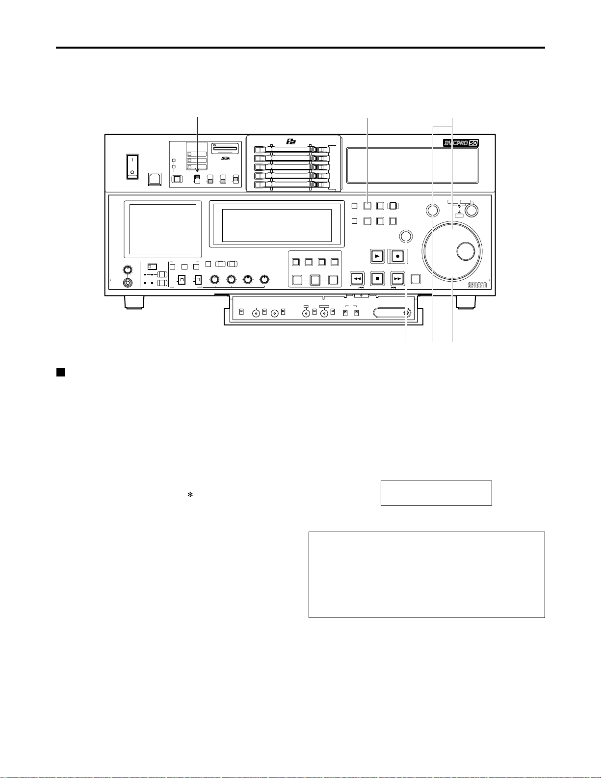
Setup (Initial settings)
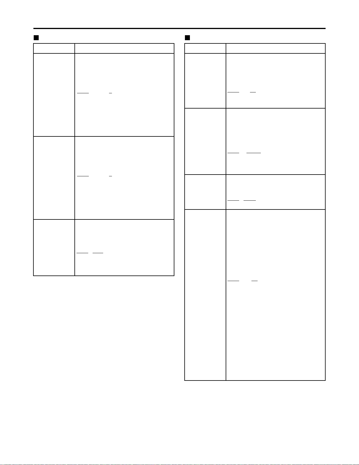
The memory card recorder’s main settings are performed while making selections using a system of menus.
If a TV monitor has been connected to the VIDEO OUT 3 connector or SDI OUT 3 connector (optional) on the rear
panel and the SUPER switch is set to [ON], the setting menus are displayed on the TV monitor.
HEADPHONES
PULL PULL
AUDIO MIX
1&2
CH1/3 CH2/4
REC CH1/3
REC CH2/4
3&4
CH1/3 CH2/4
AUDIO MON SEL
AUDIO VOL SEL
LRMIX
RECPBUNITY
VAR
METER
FULL/FINE
INPUT SELECT
VIDEO AUDIO
CH 1 CH 2 CH 3 CH 4
COUNTER
MENU
TC PRESET
SELECT
SLOT
RESET
THUMBNAIL
MARKER
BAR
MENU
SET
SEARCH
RECPLAY
FFREW STOP
PREV NEXT
SHIFT
SHTL
PUSH
JOG
SLOW
Memory Card Recorder AJ-
ENC
CONTROL
REMOTE
LOCAL
VIDEO
LEVEL
PRESET
MANUAL
CHROMA
LEVEL
PRESET
MANUAL
SET UP
PRESET
BLK
MANUAL
HUE
PRESET
CHROMA PH
MANUAL
TC
REGEN
PRESET
REC RUN
FREE RUN
DIAG
ON
POWER
USB 2.0
OFF
REMOTE
LAN
USB
1
2
3
4
5
SUPER
ON
OFF
TCG
INT
EXT
MODE
PB
EE
REC INH
ON
OFF
DVCPRO 50
DVCPRO
DV
PLAY LIST EVENT
INSERT
DELETE
GO TO
ENTRY OUTIN
(1)
(6) (4) (2)
(3)
Changing the settings
(1) Press the MENU button
The setup menu screen appears on the TV monitor, and
the setup menu item number appears on the counter
display.
Each time the FF button is pressed (for about 1.5
seconds), the item number and item name are displayed
alternately.
(If a setup was performed previously, the screen on
which the last change was made is displayed.)
(2) Turn the search dial to select the item to be set
The menu screen cursor ( ) moves, and the item
number on the display flashes.
•When the dial is turned clockwise, the item number is
incremented from 001 → 002 → 003 → 004 and so on;
conversely, when it is turned counterclockwise, the
item number is decremented.
•When the FF button or REW button is pressed while
holding down the PLAY button, the next or previous
item is selected.
•Whenever possible, limit the use of the search dial to
the JOG mode.
(3) At the position where the change is to be
made, turn the search dial while holding down
the SEARCH button
The settings on the menu screen and display now flash.
When the dial is turned clockwise, the setting number is
incremented; conversely, when it is turned
counterclockwise, it is decremented.
(4) Upon completion of the setting, release the
SEARCH button
•When the search dial is in the SHTL mode, the item will
move unless the dial is set to the center position.
(5) When other items are to be changed, repeat
steps (2) to (4)
(6) Press the SET button
The changes are stored in the memory.
To disregard the new settings and restore the old settings
instead, press the MENU button.
•To return the setup contents to the factory settings
(initial settings), press the RESET button while the menu
is displayed. The following message is displayed.
If the PLAY button is now pressed, the factory settings
are reinstated.
SETUP - MENU INIT SET
YES<PLAY> / NO<STOP>
Notes:
•If the RESET button is pressed to restore the factory
settings, only the user files currently in use are
restored. The other user files remain unaffected.
•The changes made to the SYSTEM menu contents
are recorded even by pressing the MENU button to
close the menu screen.
SUPER switch (set to [ON])
Page 3
41
Setup menus
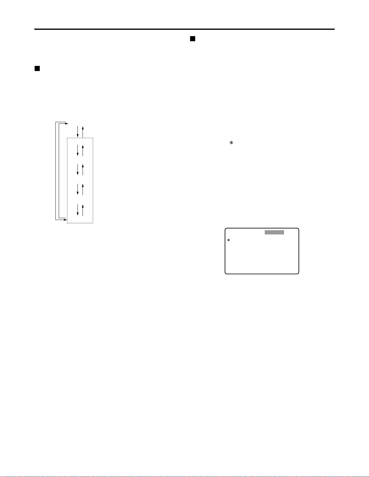
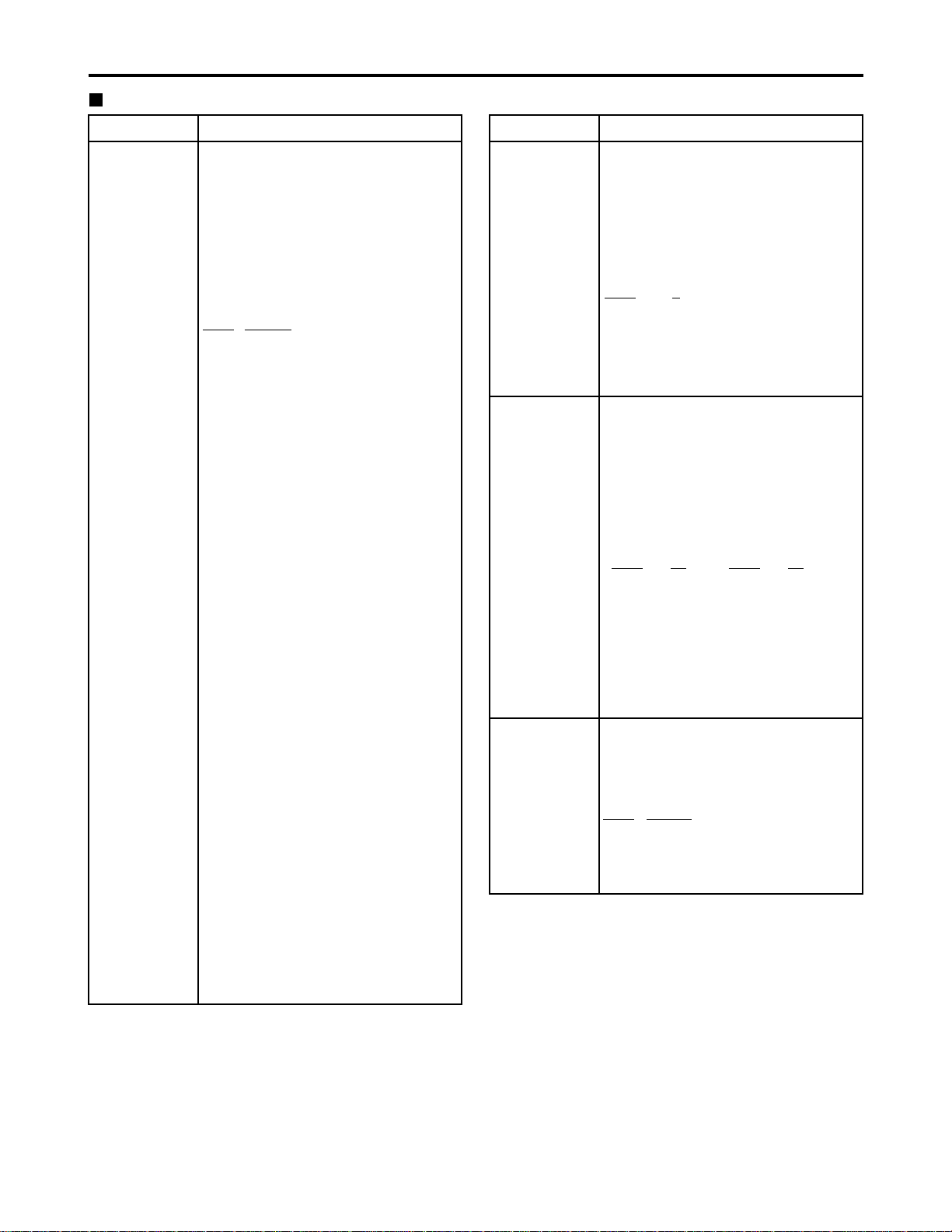
The memory card recorder can hold five user files, each of
which has its own specific menu settings, and one of these
files can be selected for use.
Changing the file
(1) Press the MENU button
(2) Press the FF button while holding down the
DIAG (or SHIFT) button to switch to the next
user file or press the REW button while holding
down the DIAG (or SHIFT) button to return to
the previous user file
Setting and releasing the lock mode
The lock mode can be set to protect the system file and
user file (USER2 to USER5) settings. Once the lock
mode is set, no further changes can be made to the
settings.
Setting and releasing the lock mode can be set for the
system file by using setup menu No. 40 (MENU LOCK)
and for the user files by using setup menu No.A03
(MENU LOCK).
(1) Press the MENU button
(2) Press the REW or FF button while holding
down the DIAG (or SHIFT) button and select the
file for which the lock mode is to be set or
released
(3) Turn the search dial
The cursor ( ) on the menu screen is moved to No. 40
(MENU LOCK) for the system file or to No. A03 (MENU
LOCK) for a user file.
(4) Turn the search dial while holding down the
SEARCH button to select whether the lock
mode is to be set or released
To set the lock mode:
Set 0001 (ON) as the setting.
To release the lock mode:
Set 0000 (OFF) as the setting.
When the lock mode has been set, “LOCKED” flashes
on the menu screen. The counter display stops flashing
and remains lighted.
(3) To enter the selection made in step (2) for the
user file which is to be used, press the SET
button
The user file is changed and stored in the memory.
Note:
Since the SYSTEM menu items are not included in user
files 1 through 5, first select the user file and switch to the
SYSTEM file, and then set the SYSTEM menu items.
SYSTEM
USER 1
USER 2
USER 3
USER 4
USER 5
FFFFREW
REW
FF REW
FF REW
FF REW
FF REW
User files
Each user file contains the
following items.
• BASIC
• OPERATION
• INTERFACE
• EDIT
• TIME CODE
• VIDEO
• AUDIO
• V BLANK
• LCD
• MENU
SETUP-MENU
<USER2>
000
001
002
003
008
009
010
011
012
P-ROLL TIME
LOCAL ENA
CTL DISP
REMAIN SEL
DISPLAY SEL
CHARA H-POS
CHARA V-POS
CHARA TYPE
SYS FORMAT
5s
STOP
±12h
2L
T&STA
4
18
WHITE
50M
NO .000-0005
LOCKED
(5) Press the SET button
The setting is stored in the memory.
Notes:
• The lock mode cannot be set for the USER1 file.
•Once set to the lock mode, a file cannot be reset to the
factory settings even by pressing the RESET button.
Page 4
42
Setup menus (continued)
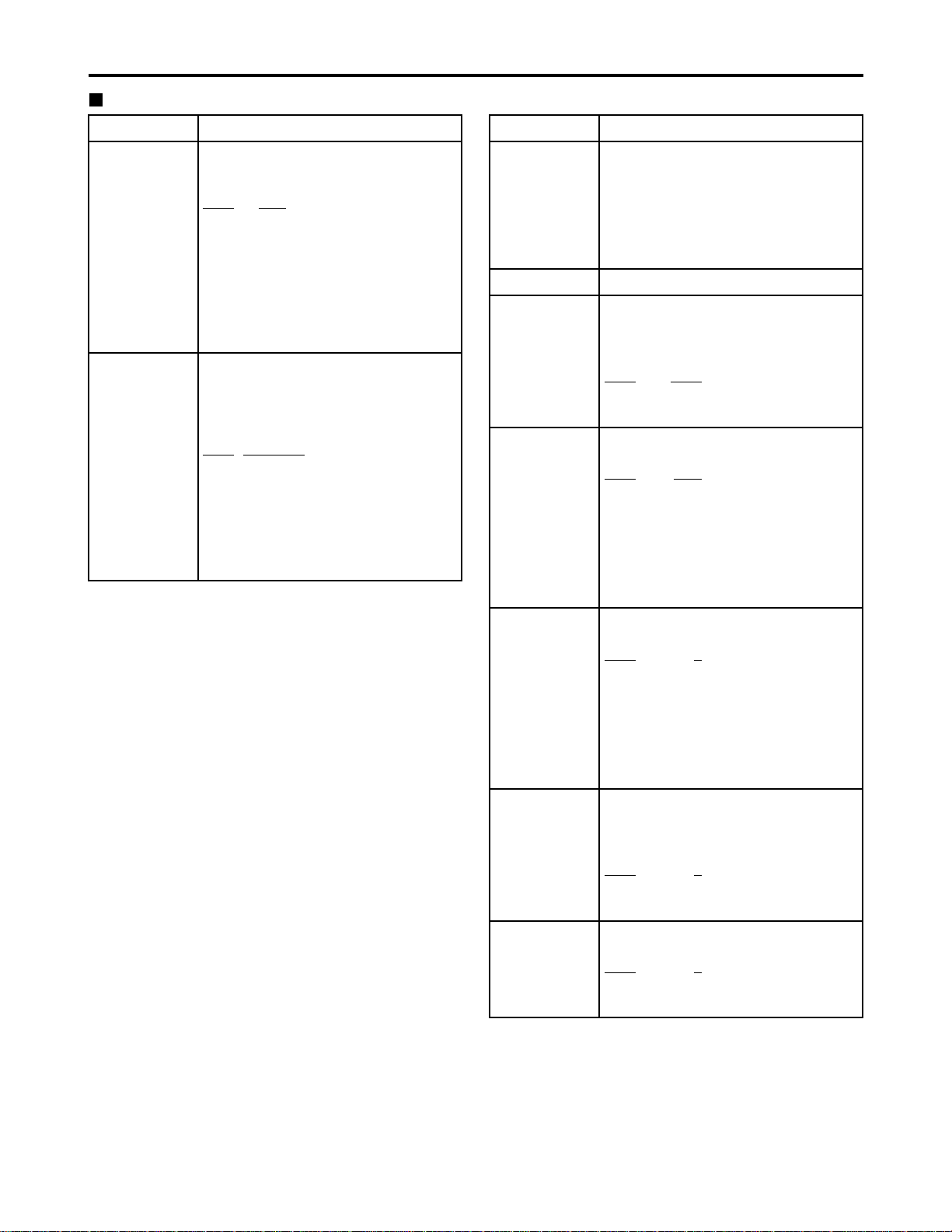
Loading user files
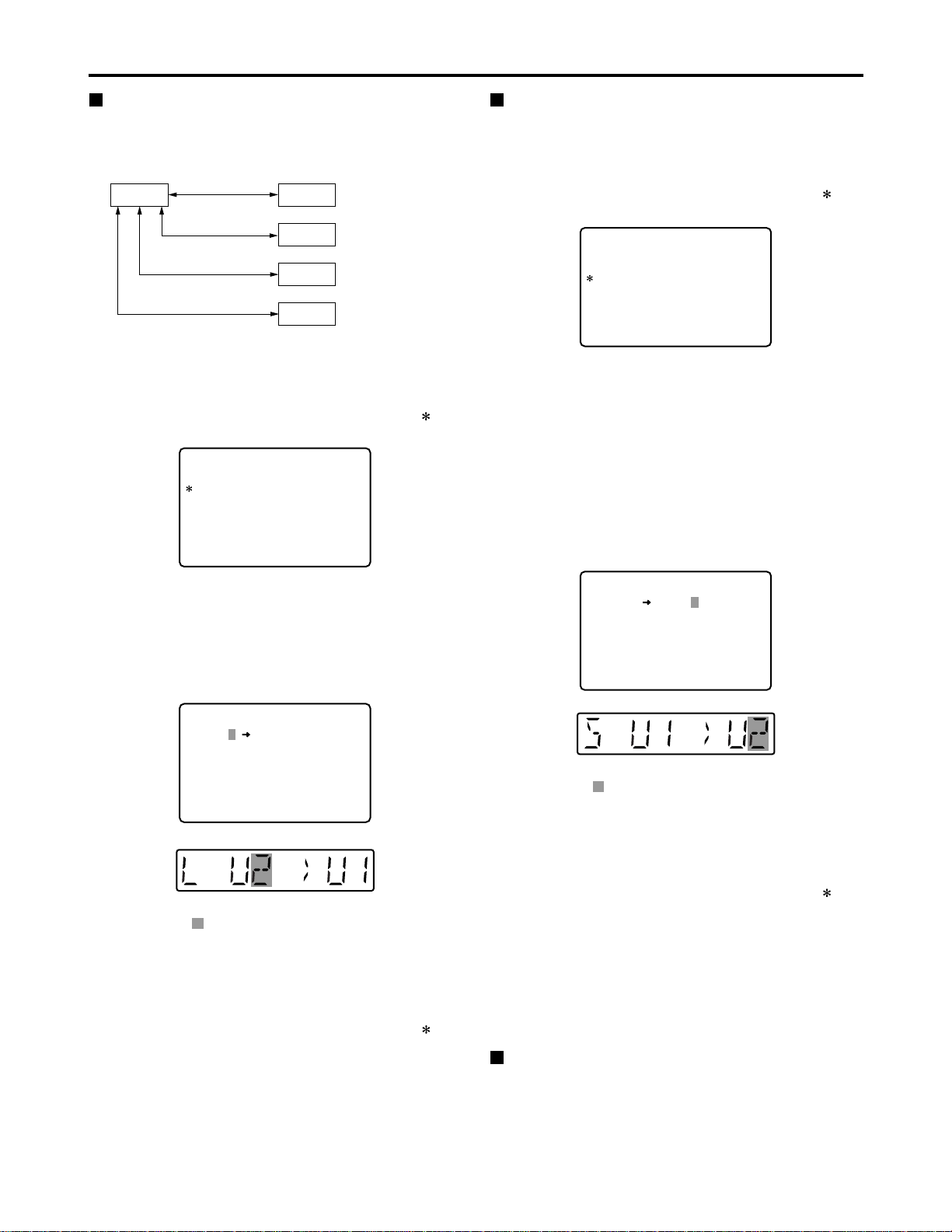
The contents of the USER2, USER3, USER4 or USER5
file can be copied (loaded) into the USER1 file. Also, the
contents of the USER1 file can be copied (saved) into the
USER2, USER3, USER4 or USER5 file.
(1) Press the MENU button
(2) Press the REW or FF button while holding
down the DIAG (or SHIFT) button and select
USER1 file
(3) Turn the search dial to move the cursor ( ) on
the menu screen to No. A00 (LOAD)
USER 1 USER 2
USER 3
USER 4
USER 5
Load/save
Lock mode can be
set
Lock mode can be
set
Lock mode can be
set
Lock mode can be
set
Load/save
Load/save
Load/save
SETUP-MENU
<USER1>
902
A00
A01
A02
END
GUI OUTPUT
LOAD
SAVE
P. ON LOAD
OFF
USER2
USER2
OFF
NO .A00-0000
MENU
SETUP-MENU
<USER1>
902
A00
A01
A02
END
GUI OUTPUT
LOAD
SAVE
P. ON LOAD
OFF
USER2
USER2
OFF
NO .A00-0000
MENU
SETUP-MENU
USER2 USER1 OK?
YES<PLAY>/NO<STOP>
LOAD
(4) Turn the search dial while holding down the
SEARCH button to select the user file whose
contents are to be loaded into USER1
(5) Press the SET button
The following message appears on the menu screen
and counter display.
Counter display
The number of the user file selected in step (4) is
displayed at .
(6) Press the PLAY button
The settings of the user file selected in step (4) are
loaded, and the USER1 menu display appears. If the
STOP button is pressed instead, the settings are not
changed, and the USER1 menu display appears.
(7) Turn the search dial to move the cursor ( ) on
the menu screen to a number other than No.
A00 (LOAD) or No. A01 (SAVE)
(8) Press the SET button
The USER1 settings are stored in the memory.
If the USER1 settings are not to be stored in the
memory, do not press the SET button but press the
MENU button instead.
Saving user files
(1) Press the MENU button
(2) Press the REW or FF button while holding
down the DIAG (or SHIFT) button and select
USER1 file
(3) Turn the search dial to move the cursor ( ) on
the menu screen to No. A01 (SAVE)
(4) Turn the search dial while holding down the
SEARCH button to select the user file in which
the contents of USER1 are to be saved
Those user files which have been set to the lock mode
do not appear on the display. If all the user files have
been set to the lock mode, the “LOCKED” display
appears, and the contents of USER1 cannot be saved
into any of the user files.
(5) Press the SET button
The following message appears on the menu screen
and counter display.
SETUP-MENU
USER1 USER2 OK?
YES<PLAY>/NO<STOP>
SAVE
Counter display
The number of the user file selected in step (4) is
displayed at .
(6) Press the PLAY button
The settings of USER1 are saved in the user file
selected in step (4) and stored in the memory. If the
STOP button is pressed instead, the settings are not
changed, and the USER1 menu display appears.
(7) Turn the search dial to move the cursor ( ) on
the menu screen to a number other than No.
A00 (LOAD) or No. A01 (SAVE)
(8) Press the SET button
The USER1 settings are stored in the memory.
If the USER1 settings are not to be stored in the
memory, do not press the SET button but press the
MENU button instead.
Automatically recalling a user file when
turning on the power
If the user file to be loaded is selected in advance using
setup menu No. A02 (P. ON LOAD), the file will be
automatically loaded into USER1 when the power is
turned on.
Menu screen
Menu screen
Page 5
43
Setup menus (continued)
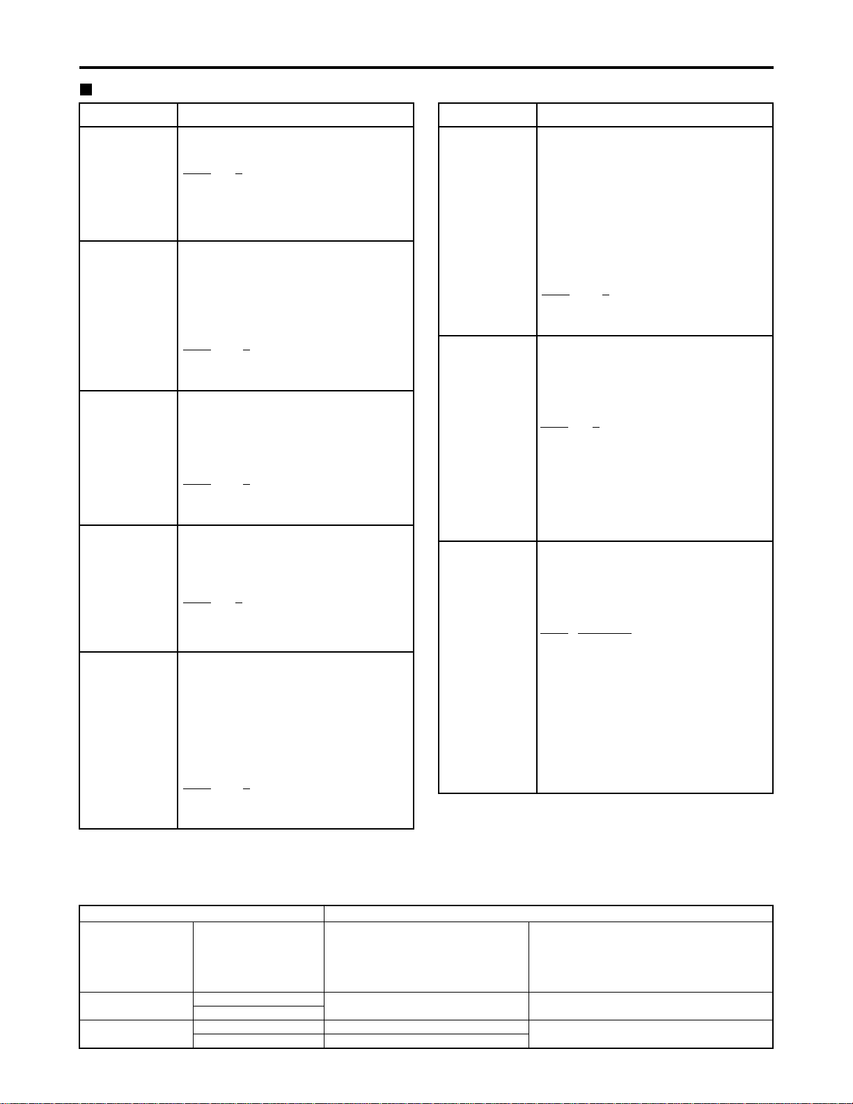
SYSTEM menu
No./Item Description
11
SYS SC COAR.
Coarse adjustment of system phase: 90 ° units
Note:
If setting operation is
performed, the setting
value does not return to
factory (default) setting.
0000
0
0001 90
0002 180
0003 270
12
SYS SC FINE
Fine adjustment of system phase:
Variable range ±45 ° or more
–: Advanced, +: Delayed
Note:
If setting operation is
performed, the setting
value does not return to
factory (default) setting.
0000 –128
::
0128
0
::
0255 127
13
SYS H
System phase adjustment: 74 ns steps
–: Advanced, +: Delayed
Note:
If setting operation is
performed, the setting
value does not return to
factory (default) setting.
0000 –128
::
0128
0
::
0216 127
No./Item Description
14
SCH COARSE
SCH phase adjustment: 90 ° units
(The SC phase changes but the H phase does not change.)
–: Advanced, +: Delayed
0000 0
0001 90
0002 180
0003 270
15
SCH FINE
SCH phase adjustment:
Total variable range: ±45 ° or more
(The SC phase changes but the H phase
does not change.)
–: Advanced, +: Delayed
0000 –32
::
0032
0
::
0064 32
16
AV PHASE
This adjusts the audio output phase
with respect to the video output:
20.8 µs steps
–: The audio output phase is advanced
with respect to the video output.
+: The audio output phase is delayed
with respect to the video output.
0000 –100
::
0100
0
::
0200 100
The underlined items indicates the initial setting.
18
SYS H OFFSET
System phase adjustment.
0000 –3: –13.4 µsec
0001 –2: –8.96 µsec
0002 –1: –4.52 µsec
0003
0 : 0 sec
0004 1 : +4.52 µsec
0005 2 : +8.96 µsec
0006 3 : +13.4 µsec
Note:
If setting operation is performed, the
setting value does not return to factory
(default) setting.
19
SYS SC/H
This sets whether the system phase is
to be adjusted by the memory card
recorder or from the external encoder
remote controller.
0000
REMOTE :
The system phase is adjusted from
the external encoder remote
controller.
0001 LOCAL :
The system phase is adjusted by the
memory card recorder.
Note:
This setting does not take effect when
LOCAL has been selected by the ENC
CONTROL switch on the front panel.
Video output signal adjustments
The video output signal adjustments are made by using the ENC CONTROL switch on the front panel and selecting the
SYSTEM menu item No. 19 (SYS SC/H) settings. A control matrix of the adjustments is shown below.
ENC CONTROL
LOCAL
REMOTE
SYSTEM menu item
19: SYS SC/H
LOCAL
REMOTE
LOCAL
REMOTE
SYSTEM menu item
11: SYS SC COAR.
12: SYS SC FINE
13: SYS H
The memory card recorder
The memory card recorder
External encoder remote controller
Front panel (under section)
VIDEO LEVEL
CHROMA LEVEL
SET UP/BLACK
HUE/CHROMA PHASE
The memory card recorder
External encoder remote controller
Setting Item adjusted
Page 6
44
USER menu <BASIC>
No./Item Description
000
P-ROLL TIME
This sets the preroll time.
The preroll time can be set from 0 to 15
seconds in 1-second increments.
0000 0s
::
0005
5s
::
0015 15s
001
LOCAL ENA
This selects the buttons which can be
operated on the front panel when the
REMOTE button is lit.
0000 DIS :
No buttons can be operated.
0001
STOP :
Only the STOP button can be operated.
0002 ENA :
All buttons can be operated.
002
CTL DISP
This selects the 12 or 24 hour display
for the CTL counter.
0000
±12h : 12 hour display
0001 24h : 24 hour display
003
REMAIN SEL
This selects whether the remaining
time or total time is to be displayed in
the superimposed display of the
VIDEO OUT 3/ SDI OUT 3 connector
(optional) signals.
0000 OFF: No display.
0001 2L :
The remaining time is displayed on
the second line.
0002
1L :
The remaining time is displayed on
the first line.
0003 R/TTL :
The remaining time is displayed on
the first line, and the total time is
displayed in the second line.
Notes:
• When “2L” is selected, the remaining
time is not displayed if “TIME” has been
selected as the setup menu item No.
008 (DISPLAY SEL) setting.
• When “R/TTL” is selected, the total time
is not displayed if “TIME” has been
selected as the setup menu item No.
008 (DISPLAY SEL) setting.
Setup menus (continued)
No./Item Description
30
BRIGHT
This adjusts the brightness of the
LCD monitor on the front panel.
Note:
If setting operation is performed, the
setting value does not return to factory
(default) setting.
0000 –7
::
0007
0
::
0014 7
The underlined items indicates the initial setting.
31
CONTRAST
This adjusts the contrast of the LCD
monitor on the front panel.
Note:
If setting operation is performed, the
setting value does not return to factory
(default) setting.
0000 –7
::
0007
0
::
0014 7
40
MENU LOCK
This selects whether the system file
lock mode is to be engaged or
released.
0000
OFF : The lock is released (file
data can be changed).
0001 ON : The lock is engaged (file
data cannot be changed).
SYSTEM menu
Page 7
45
Setup menus (continued)
USER menu <BASIC>
The underlined items indicates the initial setting.
No./Item Description
008
DISPLAY SEL
This selects what information is to be
provided by the time code and other
superimposed displays output from
the VIDEO OUT 3/SDI OUT 3
connector (optional).
0000 TIME : Data only.
(The data indicates the value for
whichever of CTL, TC or UB currently
selected by the COUNTER button.)
0001
T&STA :
Data and operation status.
0002 T&S&M :
Data, operation status and mode.
0003 T&RT : Data and REC TIME
0004 T&YMD :
Data and REC DATE (year/month/day)
0005 T&MDY :
Data and REC DATE (month/day/year)
0006 T&DMY :
Data and REC DATE (day/month/year)
0007 T&UB :
Data and user bit.
However, when UB has been selected
with the COUNTER button, the time
code is displayed after the user bit.
0008 T&CTL :
Data and CTL data.
However, when CTL has been
selected with the COUNTER button,
the time code is displayed after the
CTL data.
0009 T&T : Data and time code.
0010 VITC:
The time code and user bit recorded
on the card are displayed.
Notes:
• Mode display:
DVCPRO 50 (50 Mbps) = DVCPRO_50,
DVCPRO (25 Mbps) = DVCPRO,
DV = DV
• An error message appears if a warning
or error has occurred when “T&S&M”
has been selected as this setting.
• The recording duration and recording
time and date are displayed when the
DV format applies. The operating
status is displayed instead when the
DVCPRO50 (50 Mbps) or DVCPRO
(25 Mbps) format applies.
No./Item Description
009
CHARA H-POS
This sets the position of the characters
on the horizontal plane for the time
code and other superimposed displays
output from the VIDEO OUT 3/ SDI OUT
3 connector (optional).
Note:
Characters may extend beyond the
edges of the screen.
0000 0
::
0004
4
::
0016 16
010
CHARA V-POS
This sets the position of the characters
on the vertical plane for the time code
and other superimposed displays
output from the VIDEO OUT 3/ SDI OUT
3 connector (optional).
Note:
When the DISPLAY SEL setting causes
characters to extend beyond the edges of
the screen, the setting value is changed so
that the characters are automatically
displayed in a position on the screen.
[625i system]
0000 0
::
0023
23
::
0028 28
[525i system]
0000 0
::
0018
18
::
0022 22
011
CHARA TYPE
This selects the display type for the
superimposed display output from the VIDEO
OUT 3/SDI OUT 3 connector (optional) as well
as for displays such as the setup menu, etc.
0000 WHITE :
White characters against a black
background.
0001 W/OUT :
White characters with a black border.
Page 8
46
Setup menus (continued)
USER menu <BASIC>
The underlined items indicates the initial setting.
No./Item DescriptionNo./Item Description
012
SYS FORMAT
This sets the memory card recorder’s
recording and playback format.
0000
50M :
DVCPRO50 (50 Mbps) is selected.
0001 25M :
DVCPRO (25 Mbps) is selected.
0002 DV :
DV (25 Mbps) is selected.
Note:
The format complies with the setting of
this menu item when the card is ejected.
017
CHARA SIZE
This selects the size of the characters
for the superimposed display output
from the VIDEO OUT 3/SDI OUT 3
connector (optional).
0000
NORMAL : Standard size
0001 LARGE :
4 times larger than the standard size
Note:
When LARGE has been selected, only
time data is displayed, regardless of the
setup menu No.008 (DISPLAY SEL)
setting.
01
MONTH
02
DAY
Sets the month.
Note:
If a nonexistent day is set while setting
Feb, April, June, September, or
November, it is set as the first day of the
following month.
0001
JAN
::
0012 DEC
Sets the day.
Note:
If a nonexistent day is set while setting
Feb, April, June, September, or
November, it is set as the first day of the
following month.
0001
1
::
0031 31
03
HOUR
Sets the hour value.
Set the value based on 24-hour clock
time.
0000
0
::
0023 23
04
MINUTE
Sets the minute value.
0000
0
::
0059 59
069
CLOCK SET
Sub-screen
Sets the internal clock time.
Note:
Press the STOP button to display a subscreen for selecting the line to be
recorded. Press the STOP button again
to return from the sub-screen.
00
YEAR
Sets the year.
0000 2000
::
0004
2004
::
0030 2030
Page 9

47
Setup menus (continued)
USER menu <BASIC>
No./Item Description
05
TIME ZONE
Sets the time difference from the
world standard time.
Refer to the table below, and select the
setting which corresponds to the local
time.
0000
00:00
0001 +00:30
0002 +01:00
::
0050 –00:30
No./Item Description
070
TV SYSTEM
This selects the TV system.
0000:
The 525 interlace/59.94 Hz system is
selected.
0001:
The 625 interlace/50 Hz system is
selected.
Notes:
• After this setting is changed, turn off
and back on the power again to take it
effect.
• Analog video signals cannot be
selected using INPUT SELECT once
the TV system has been changed from
the factory setting.
• When the setting is changed, the play
list is reset.
[625i system]
0000 525
0001
625
[525i system]
0000
525
0001 625
Time
City/region
Time
City/region
difference difference
00:00 Greenwich + 13:00
- 00:30 + 10:30
Lord Howe Island
- 01:00 Azores + 12:00 New Zealand
- 01:30 + 09:30 Darwin Islands
- 02:00
Central Atlantic time
+ 11:00 Solomon Islands
- 02:30 + 08:30
- 03:00 Buenos Aires + 10:00 Guam
- 03:30 Newfoundland + 07:30
- 04:00 Halifax + 09:00 Tokyo
- 04:30 + 06:30 Rangoon
- 05:00 New York + 08:00 Beijing
- 05:30 + 05:30 Bombay
- 06:00 Chicago + 07:00 Bangkok
- 06:30 + 04:30 Kabul
- 07:00 Denver + 06:00 Dacca
- 07:30 + 03:30 Teheran
- 08:00 Los Angeles + 05:00 Islamabad
- 08:30 + 02:30
- 09:00 Alaska + 04:00 Abu Dhabi
- 09:30
Marquesas Islands
+ 01:30
- 10:00 Hawaii + 03:00 Moscow
- 10:30 + 00:30
- 11:00 Midway Islands + 02:00 Eastern Europe
- 11:30 + 12:45
Chatham Islands
- 12:00 Kwajalein Atoll + 01:00 Central Europe
+ 11:30 Norfolk Islands
Note:
The clock has an accuracy equivalent to a monthly error
of ±30 seconds with the power OFF. When the precise
time is required, check the time and reset it while the
power is ON.
Page 10

48
Setup menus (continued)
The underlined items indicates the initial setting.
No./Item Description
100
SEARCH ENA
This selects the direct search dial
operation.
0000
DIAL :
For direct search dial operations.
0001 KEY :
Operation is not transferred to the
search mode unless the search button
is pressed.
101
SHTL MAX
This sets the maximum speed for
shuttle operations.
0000 x8 : 8x normal speed
0001 x16 : 16x normal speed
0002
x32 : 32x normal speed
0003 x60 : 60x normal speed
0004 x100 : 100x normal speed
104
REF ALARM
This selects whether to warn the
operator when the REF. VIDEO signal
has not been connected.
0000 OFF :
Warning is not given.
0001
ON :
Warning is given by the flashing
STOP lamp.
Note:
Video and audio output may be disturbed
when the reference video signal is not
input, so it is recommended that a
system which inputs the reference video
signal be used.
102
FF. REW MAX
This sets the maximum speed for FF
and REW operations.
0000 x32 : 32x normal speed
0001 x60 : 60x normal speed
0002
x100 : 100x normal speed
USER menu <OPERATION>
No./Item Description
105
AUTO EE SEL
This selects the memory card
recorder mode in which the EE status
is established when the MODE switch
is set to EE.
0000 S/F/R :
EE status is established in STOP, FF
and REW modes.
However, EE status is established at
all times when the card is ejected,
regardless of the MODE switch
setting.
0001
STOP :
EE status is established in STOP
mode.
However, EE status is established at
all times when the card is ejected,
regardless of the MODE switch
setting.
0002 BLACK :
EE status is established in STOP
mode.
However, when the card is ejected, if
the MODE switch is set to;
EE: EE status is established.
PB: The picture becomes black and
the sound is muted.
0003 BLACK1 :
EE status is established in STOP, FF
and REW modes.
However, when the card is ejected, if
the MODE switch is set to;
EE: EE status is established.
PB: The picture becomes black and
the sound is muted.
0004 GRAY :
EE status is established in STOP
mode.
However, when the card is ejected, if
the MODE switch is set to;
EE: EE status is established.
PB: The picture becomes gray and
the sound is muted.
0005 GRAY1 :
EE status is established in STOP, FF
and REW modes.
However, when the card is ejected, if
the MODE switch is set to;
EE: EE status is established.
PB: The picture becomes gray and
the sound is muted.
Page 11

49
Setup menus (continued)
No./Item Description
USER menu <OPERATION>
113
A IN SEL INH
This selects whether audio input
switching using the INPUT SELECT
button is to be enabled or disabled.
0000 OFF :
Audio input switching using the INPUT
SELECT button is enabled.
0001 ON :
Audio input switching using the INPUT
SELECT button is disabled.
0002
REC :
Audio input switching using the INPUT
SELECT button after the memory card
recorder has been transferred to a
recording mode is disabled.
Note:
Even when the ON or REC setting is
selected to disable audio input switching
using the INPUT SELECT button, it is
still possible to set the setup menu items
No. 715 (CH1 IN SEL), No. 716 (CH2 IN
SEL), No. 717 (CH3 IN SEL), No. 718
(CH4 IN SEL), No. 719 (D IN SEL12)
and No. 720 (D IN SEL34).
112
V IN SEL INH
This selects whether video input
switching using the INPUT SELECT
button is to be enabled or disabled.
0000 OFF :
Video input switching using the INPUT
SELECT button is enabled.
0001 ON :
Video input switching using the INPUT
SELECT button is disabled.
0002
REC :
Video input switching using the INPUT
SELECT button after the memory card
recorder has been transferred to a
recording mode is disabled.
The underlined items indicates the initial setting.
No./Item Description
107
PLAY DELAY
This set the play delay time in frame
increments.
0000
0
::
0015 15
106
EE MODE SEL
This selects the EE mode output
signals.
0000
NORMAL :
Signals are output with a delay
equivalent to the length of internal
signal processing.
0001 THRU :
Signals are output directly, without
internal processing, and so are output
with no delay.
Note:
When 1394 has been selected for the
video input signals or when INT SG has
been selected for video or audio, internal
operations are forcibly set to NORMAL.
Page 12

50
Setup menus (continued)
The underlined items indicates the initial setting.
No./Item Description
USER menu <INTERFACE>
201
9P SEL
This selects whether the REMOTE
(9P) connector functions when the
REMOTE button is lit.
0000 OFF :
Connector does not function.
0001
ON : Connector functions.
204
RS232C SEL
This selects whether the RS-232C
connector functions when the
REMOTE button is lit.
0000
OFF :
Connector does not function.
0001 ON : Connector functions.
205
BAUD RATE
These settings are for selecting the
RS-232C communication speed (baud
rate). (Unit: Bps)
0000 300
0001 600
0002 1200
0003 2400
0004 4800
0005
9600
206
DATA LENGTH
These settings are for selecting the
RS-232C data length. (Unit: bit)
0000 7
0001
8
202
ID SEL
This sets the ID information to be
returned to the controller.
0000 OTHER
0001
DVCPRO
0002 ORIG
Notes:
• ID information of any VTR except for
the DVCPRO’s is set in OTHER.
• Select ORIG only when the unit has
been connected to the specified
controller.
207
STOP BIT
These settings are for selecting the
RS-232C stop bit length. (Unit: bit)
0000
1
0001 2
No./Item Description
208
PARITY
These settings are for selecting the
none, odd or even for the RS-232C
parity bit.
0000
NON :
Parity bit is not used.
0001 ODD:
An odd number of bits is used for the
parity system.
0002 EVEN:
An even number of bits is used for the
parity system.
209
RETURN ACK
These settings are for selecting
whether the ACK code is to be
returned when a command is received
from RS-232C.
0000 OFF : ACK code is not returned.
0001
ON : ACK code is returned.
Page 13

51
Setup menus (continued)
No./Item Description
USER menu <EDIT>
303
STD/NON-STD
This selects STD or NON-STD in
accordance with the composite input
signal.
0000
AUTO :
Standard/non-standard signals are
automatically identified and
processed.
0001 STD :
Standard signals are processed.
(Forced STD)
0002 N-STD :
Non-standard signals are processed.
(Forced NON-STD)
Notes:
• Use the non-standard (NON-STD)
setting when video or audio trouble
occurs with signals from laser discs or a
satellite.
• At the NON-STD setting, the images
shown on the front panel's LCD monitor
will be significantly disrupted when the
unit's operation is transferred from the
play mode to EE mode: this is normal
and not indicative of malfunctioning.
304
REF LOCK
This selects the REF LOCK mode.
0000
AUTO :
Servo is synchronized with the input
signal during recording, or with the
REF signal during playback.
0001 EXT :
Servo is synchronized at all times with
the REF signal.
0002 AUTO1 :
Servo is synchronized with the input
signal during recording, or with the
REF signal during playback.
When there is no reference (REF)
signal, the EE output is synchronized
with the internal reference signal at
the AUTO setting or with the STD
input signal at the AUTO1 setting.
The AUTO1 setting is selected when
the STD signal is to be used.
Note:
At the AUTO setting, the images shown
on the front panel's LCD monitor will be
significantly disrupted when the unit's
operation is transferred from the play
mode to EE mode: this is normal and not
indicative of malfunctioning.
315
AFTER
CUE-UP
This selects the mode after cue-up
operation is complete.
0000
STOP : STOP mode
0001 STILL : SHTL STILL mode
320
VAR FWD MAX
This sets the maximum SLOW FWD
speed.
0000
+4 : +4x speed
0001 +2 : +2x speed
0002 +1 : +1x speed
Note:
At any speed setting other than 0 (+4),
the phase cannot be synchronized from
the editing controller.
321
VAR REV MAX
This sets the maximum SLOW REV
speed.
0000
–4 : –4x speed
0001 –2 : –2x speed
0002 –1 : –1x speed
No./Item Description
323
JOG FWD MAX
This sets the maximum JOG FWD
speed.
0000 +4 : +4x speed
0001 +2 : +2x speed
0002
+1 : +1x speed
Notes:
• The maximum speed is set to +1 x
when the dial on the front panel is
operated.
• At any speed setting other than 0 (+4),
the phase cannot be synchronized from
an editing controller which synchronizes
the phase using the JOG command.
324
JOG REV MAX
This sets the maximum JOG REV
speed.
0000 –4 : –4x speed
0001 –2 : –2x speed
0002
–1 : –1x speed
Note:
The maximum speed is set to –1 x when
the dial on the front panel is operated.
The underlined items indicates the initial setting.
Page 14

52
Setup menus (continued)
No./Item Description
USER menu <TIME CODE>
500
VITC BLANK
This selects whether to output the
VITC signal at the positions selected
by setup menu items No. 501 (VITC
POS-1) and No. 502 (VITC POS-2).
0000 BLANK :
VITC signals are not output.
0001
THRU :
VITC signals are output.
501
VITC POS-1
This sets the position where the VITC
signal is to be inserted.
Note:
The same line as the one used for the
setup menu items No. 502 (VITC POS-2)
and No. 662 (UMID POS) setting cannot
be set.
[625i system]
0000 7L
::
0004
11L
::
0015 22L
[525i system]
0000 10L
::
0006
16L
::
0010 20L
502
VITC POS-2
This sets the position where the VITC
signal is to be inserted.
Note:
The same line as the one used for the
setup menu items No. 501 (VITC POS-1)
and No. 662(UMID POS) setting cannot
be set.
[625i system]
0000 7L
::
0006
13L
::
0015 22L
[525i system]
0000 10L
::
0008
18L
::
0010 20L
503
TCG REGEN
This selects the signal to be
regenerated when the time code
generator (TCG) in the REGEN mode.
0000
TC&UB :
Both the time code and user bit are
regenerated.
0001 TC :
Only the time code is regenerated.
0002 UB :
Only the user bit is regenerated.
505
EXT TC SEL
This selects the time code to be used
when an external time code is to be
used.
0000
LTC :
The LTC of the TIME CODE IN
connector is used.
0001 VITC :
The VITC of the input video signal is used.
Note:
During recording, there is a discrepancy
in the picture and superimposed TC
value displayed, but the actual recording
is not adversely affected in any way.
No./Item Description
506
BINARY GP
This sets the usage status of the user
bit of the time code generated by the
TCG.
0000
000 :
NOT SPECIFIED (character set not
specified)
0001 001 :
ISO CHARACTER (8 bits character
set based on ISO646, ISO2022)
0002 010 : UNASSIGNED 1 (undefined)
0003 011 : UNASSIGNED 2 (undefined)
0004 100 : UNASSIGNED 3 (undefined)
0005 101 : PAGE/LINE
0006 110 : UNASSIGNED 4 (undefined)
0007 111 : UNASSIGNED 5 (undefined)
507
PHASE CORR
This selects whether to control the
phase correction of the LTC which is
output from the TIME CODE OUT
connector.
0000
OFF :
Phase correction control is not
performed.
0001 ON :
Phase correction control is performed.
508
TCG CF FLAG
This selects whether the CF flag of
the TCG is to ON.
0000
OFF : CF flag is OFF.
0001 ON : CF flag is ON.
509
DF MODE
This selects the DF or NDF mode for
CTL and TCG.
0000
DF :
The drop frame mode is used.
0001 NDF :
The non-drop frame mode is used.
Notes:
• Drop frame mode is valid only when the
REMOTE button is lit or the setup menu
No. 001 (LOCAL ENA) is set to ENA.
• This menu option is not displayed in the
625i system.
The underlined items indicates the initial setting.
Page 15

53
Setup menus (continued)
No./Item Description
USER menu <TIME CODE> USER menu <VIDEO>
510
TC OUT REF
This is used to switch the phase of
the time code, which is output from
the TIME CODE OUT connector, for
the external LTC input when the TCG
switch is at the “EXT” position.
0000
V OUT :
Time code is synchronized with output
video signal.
0001 TC_IN :
Time code is synchronized with
external time code input.
511
VITC OUT
This selects how the VITC which is to
be superimposed onto the output
video signal during playback is to be
output.
0000
SBC :
The time code recorded in the sub
code area is output as the VITC.
0001 VAUX :
The time code recorded in the VAUX
area is output as the VITC.
514
VITC GEN
This selects whether or not to record
the internal time code generator value
in the VAUX area.
0000
OFF :
The internal time code generator
value is not recorded in the VAUX
area.
When video signals on which the time
code has been recorded are input, the
time code of the input signals is
recorded in the VAUX area.
0001 ON :
The internal time code generator
value is recorded in the VAUX area.
Note:
If 1394 has been selected as the input
signals, the time code on the input
compressed signals will be recorded
regardless of this menu’s setting.
The underlined items indicates the initial setting.
No./Item Description
600
INT SG
This selects the internal signal.
0001 BB :
The black burst is generated.
0002 CB100 :
100% color bars are generated.
0003
CB75 :
75% color bars are generated.
601
OUT VSYNC
This selects whether to float the
vertical sync position of the video
output in order to align the video
output phase with the input in the
EE/record/edit modes.
0000
N-VF : Signals are not floated.
0001 VF : Signals are floated.
603
CC (F1)
BLANK
This selects ON or OFF for the closed
caption signal of the first field.
0000 BLANK :
Signal is forcibly blanked.
0001
THRU : Signal is not blanked.
Note:
This menu option is not displayed in the
625i system.
604
CC (F2)
BLANK
This selects ON or OFF for the closed
caption signal of the second field.
0000 BLANK :
Signal is forcibly blanked.
0001
THRU : Signal is not blanked.
Note:
This menu option is not displayed in the
625i system.
605
FREEZE SEL
This selects the freeze mode for still
pictures.
0000
FIELD : Field freeze.
0001 FRAME : Frame freeze.
Notes:
• When frame freeze has been selected,
the frame slow status is established
with the slow setting.
• This setting is also followed when there
is a freeze command from the RS-422A
connector, but the picture displayed on
the LCD monitor screen shown at this
time will not be frozen.
606
OUT C KILL
This selects chroma color killer
processing for the video output
signals.
0000 B/W :
No color signals are output.
0001
COLOR :
Color signals are output.
Sub code area:
This area is separate from the video and audio data area on
the P2 card. The time code complying with SMPTE/EBU
standards is stored here.
VAUX area:
This area is to be found in the video data area on the P2 card.
The additional information relating to the video data is
stored here.
Page 16

54
No./Item Description
620
ESR MODE
This selects the operation mode for
edge subcarrier reduction (ESR) in
the playback circuit.
0000 OFF :
The mode is forcibly set to OFF.
0001
AUTO :
The mode is automatically set to ON
or OFF depending on the memory
card recorder operation.
621
CCR MODE
This selects the cross color
processing during playback.
0000
OFF :
The cross color is output with no
changes made.
0001 ON :
The cross color can be reduced.
Note:
This menu option is not displayed in the
625i system.
624
CC REC
This selects whether to record the
closed caption signals multiplexed on
the input signals on the card.
0000
OFF
:
No closed caption signal is recorded.
In addition, the EE output signals are
blanked.
0001 ON :
When a closed caption signal is
detected from the selected input
signal, it can be recorded on the card.
Notes:
• This menu option is not displayed in the
625i system.
• If 1394 has been selected as the input
signals, the closed caption signal on the
input compressed signals will be
recorded regardless of this menu’s
setting.
645
WIDE SELECT
This selects whether to record the
WIDE information on the card.
0001 WIDE :
The information is recorded.
0002
NORMAL :
No information is recorded.
Note:
If 1394 has been selected as the input
signals, the input information will be
recorded.
Setup menus (continued)
USER menu <VIDEO>
No./Item Description
609
EDH
This selects whether to superimpose
EDH onto the SDI output signals.
0000 OFF : EDH is not superimposed.
0001
ON : EDH is superimposed.
Note:
Even when ON is selected for this
setting, EDH is not superimposed onto
the signals output from the SDI OUT 3
connector (optional) if the SUPER switch
on the front panel is set to ON.
610
P
B/PR IN LV
This selects the analog component
input level.
0000 M II : M II level
0001
B-CAM : ß-CAM level
Note:
This menu option is not displayed in the
625i system.
611
YC SEP MODE
This selects Y/C separation
processing for the composite input
signals.
0000 B/W :
The signals are processed as B/W
signals.
0001
AUTO :
The signals are automatically
detected.
614
P
B
/PR OUT LV
This selects the analog component
output level.
0000 M II : M II level
0001
B-CAM : ß-CAM level
Note:
This menu option is not displayed in the
625i system.
The underlined items indicates the initial setting.
618
INTERPOLATE
This selects the interpolation
operation.
Vertical interpolation is conducted
automatically during slow-motion
playback to reduce the vertical
movement of the playback pictures.
However, this menu item enables the
interpolation operation to be forcibly
turned off.
0000 OFF :
Interpolation is forcibly turned off.
0001
AUTO :
Interpolation is automatically turned
on during slow-motion playback.
Page 17

55
Setup menus (continued)
The underlined items indicates the initial setting.
USER menu <VIDEO>
No./Item Description
622
SETUP 25
(For AJ-SPD850P)
Sub-screen
For setting 7.5% setup processing to be
performed on input and output signals
in the DVCPRO (25 Mbps) mode.
When the STOP button is pressed,
operation is transferred to the subscreen, and the setup level is set for
each output. To return from the subscreen, press the STOP button again.
Note:
This setup menu is not displayed in the
625i system.
00
CMPST IN
This selects the 7.5% setup processing
for the input composite signal.
0000 THRU :
The signal is recorded in its original
form.
0001
CUT :
The signal is recorded with the 7.5%
setup removed.
02
CMPNT IN
This selects the 7.5% setup processing
for the input component signal.
0000 THRU :
The signal is recorded in its original form.
0001 CUT :
The signal is recorded with the 7.5%
setup removed.
01
CMPST OUT
This selects the 7.5% setup processing
for the output composite signal.
0000 THRU :
The signal is output in its original form.
0001 ADD :
The signal is output with the 7.5%
setup added.
Note:
Bear in mind the setting for sub-screen
item No. 03 (CMPNT OUT) of setup
menu item No. 622 (SETUP 25).
03
CMPNT OUT
This selects the 7.5% setup processing
for the output composite, component
and serial (digital) signal.
0000 THRU :
The signal is output in its original form.
0001 CUT :
The signal is output with the 7.5%
setup removed.
0002 ADD :
The signal is output with the 7.5%
setup added.
No./Item Description
623
SETUP 50
(For AJ-SPD850P)
Sub-screen
For setting 7.5% setup processing to be
performed on input and output signals
in the DVCPRO50 (50 Mbps) mode.
When the STOP button is pressed,
operation is transferred to the subscreen, and the setup level is set for
each output. To return from the subscreen, press the STOP button again.
Note:
This setup menu is not displayed in the
625i system.
00
CMPST IN
This selects the 7.5% setup processing
for the input composite signal.
0000 THRU :
The signal is recorded in its original
form.
0001
CUT :
The signal is recorded with the 7.5%
setup removed.
02
CMPNT IN
This selects the 7.5% setup processing
for the input component signal.
0000 THRU :
The signal is recorded in its original form.
0001 CUT :
The signal is recorded with the 7.5%
setup removed.
01
CMPST OUT
This selects the 7.5% setup processing
for the output composite signal.
0000 THRU :
The signal is output in its original form.
0001 ADD :
The signal is output with the 7.5%
setup added.
Note:
Bear in mind the setting for sub-screen
item No. 03 (CMPNT OUT) of setup
menu item No. 623 (SETUP 50).
03
CMPNT OUT
This selects the 7.5% setup processing
for the output composite, component
and serial (digital) signal.
0000 THRU :
The signal is output in its original form.
0001 CUT :
The signal is output with the 7.5%
setup removed.
0002 ADD :
The signal is output with the 7.5%
setup added.
Page 18

56
Setup menus (continued)
USER menu <VIDEO>
No./Item Description
660
UMID REC
This selects whether or not to record
the UMID information on the card.
0000 OFF :
UMID information is not recorded on
the card. In addition, EE output
signals are blanked.
0001
ON :
UMID information is recorded on the
card.
Note:
If THRU has been selected as the setup
menu item No. 106 (EE MODE SEL)
setting, UMID information of the EE
output signals will be blanked.
661
UMID GEN
This selects the UMID information to be
recorded on the card when ON has been
selected as the setup menu item No. 660
(UMID REC) setting.
0000 INT :
Newly created UMID information of
this unit is always recorded.
0001
EXT
:
The UMID information of the input
signals is recorded.
Newly created UMID information of
this unit is recorded if there is no
UMID information on the input signals.
662
UMID POS
This sets the line on which the UMID
information is to be superimposed.
Note:
The line selected for the setup menu
item No. 501 (VITC POS-1) and No. 502
(VITC POS-2) settings cannot be
selected for this item.
[625i system]
0000 BLANK
0001 18L
::
0010
17L
::
0015 22L
[525i system]
0000 BLANK
0001 12L
::
0006
17L
::
0008 19L
The underlined items indicates the initial setting.
No./Item Description
USER menu <AUDIO>
701
CH1 IN LV
This selects the audio input (CH1)
reference level switching.
0000 4dB
0001
0dB
0002 –20dB
702
CH2 IN LV
This selects the audio input (CH2)
reference level switching.
0000 4dB
0001
0dB
0002 –20dB
703
CH3 IN LV
This selects the audio input (CH3)
reference level switching.
0000 4dB
0001
0dB
0002 –20dB
704
CH4 IN LV
This selects the audio input (CH4)
reference level switching.
0000 4dB
0001
0dB
0002 –20dB
706
CH1 OUT LV
This selects the audio output (CH1)
reference level switching.
0000 4dB
0001
0dB
0002 –20dB
707
CH2 OUT LV
This selects the audio output (CH2)
reference level switching.
0000 4dB
0001
0dB
0002 –20dB
708
CH3 OUT LV
This selects the audio output (CH3)
reference level switching.
0000 4dB
0001
0dB
0002 –20dB
709
CH4 OUT LV
This selects the audio output (CH4)
reference level switching.
0000 4dB
0001
0dB
0002 –20dB
Page 19

57
No./Item Description
727
PB FADE
This selects the processing method
for the audio edit points (IN point,
OUT point) during playback etc.
0000
AUTO :
The processing method accords with
the status established during
recording.
0001 CUT : Forced CUT
0002 FADE : Forced FADE
728
EMBEDDED
AUD
This selects whether to superimpose
the audio data onto the SDI output.
0000 OFF : Data is not superimposed.
0001
ON
: Data is superimposed.
734
MONI SEL
INH
This selects whether the operation of
the MONITOR SELECT button on the
front panel is to be enabled or
disabled.
0000
OFF : Operation is enabled.
0001 ON : Operation is disabled.
0002 ON1 :
Operation is disabled in the FULL
display mode and enabled only in the
FINE display mode.
Setup menus (continued)
USER menu <AUDIO>
No./Item Description
711
MONIL OUT
LV
This selects the audio monitor output
(Lch) reference level switching.
0000 4dB
0001
0dB
0002 –20dB
712
MONIR OUT
LV
This selects the audio monitor output
(Rch) reference level switching.
0000 4dB
0001
0dB
0002 –20dB
713
MONI OUT
This selects whether to link the
volume level of the audio monitor
output to the setting of the
headphone volume control.
0000 UNITY :
The sound is output at a fixed level
regardless of the position of the
volume control.
0001
VAR :
The volume level is linked to the
setting of the volume control.
715
CH1 IN SEL
This selects the CH1 input when
USER SET has been selected by
pressing the memory card recorder’s
AUDIO INPUT SELECT button.
0000
ANA : Analog input.
0001 DIGI : Digital input.
716
CH2 IN SEL
This selects the CH2 input when
USER SET has been selected by
pressing the memory card recorder’s
AUDIO INPUT SELECT button.
0000
ANA : Analog input.
0001 DIGI : Digital input.
717
CH3 IN SEL
This selects the CH3 input when
USER SET has been selected by
pressing the memory card recorder’s
AUDIO INPUT SELECT button.
0000
ANA : Analog input.
0001 DIGI : Digital input.
718
CH4 IN SEL
This selects the CH4 input when
USER SET has been selected by
pressing the memory card recorder’s
AUDIO INPUT SELECT button.
0000
ANA : Analog input.
0001 DIGI : Digital input.
719
D IN SEL12
This selects the CH1 and CH2 digital
input when USER SET has been selected
by pressing the memory card recorder’s
AUDIO INPUT SELECT button.
0000 AES : AES input
0001 SIF : SDI input
720
D IN SEL34
This selects the CH3 and CH4 digital
input when USER SET has been selected
by pressing the memory card recorder’s
AUDIO INPUT SELECT button.
0000 AES : AES input
0001 SIF : SDI input
The underlined items indicates the initial setting.
754
AMIX SEL INH
This selects the input audio channel
switching mode using the REC
CH1/CH3 and REC CH2/CH4 buttons.
0000
OFF :
The audio input channels can be
switched using the REC CH buttons.
0001 ON :
Switching of the audio input channels
using the REC CH buttons is
prohibited.
0002 REC :
After the unit's operation has been
transferred to recording, switching of
the audio input channels using the
REC CH buttons is prohibited.
Page 20

58
Setup menus (continued)
No./Item Description
USER menu <V BLANK>
800
ADD LINE 25
Sub-screen
00
REC LINE1
This selects the additional line where
the signals are to be recorded.
[625i system]
0000 7L
::
0002 9L
::
0015 22L
0016 320L
::
0031 335L
0032
623L
[525i system]
0000 10L
::
0002 12L
::
0012 22L
0013 263L
0014 273L
::
0025 284L
0026
525L
01
REC LINE2
This selects the additional line where
the signals are to be recorded.
Note:
This menu option is not displayed when
additional line mode setting “1” through
“5” has been selected.
[625i system]
0000 7L
: :
0015 22L
0016 320L
::
0018
322L
::
0031 335L
0032 623L
[525i system]
0000 10L
::
0012 22L
0013 263L
0014 273L
::
0016
275L
::
0025 284L
0026 525L
No./Item Description
The underlined items indicates the initial setting.
This selects the mode for recording
signals on additional lines.
0000 OFF :
No signals are recorded on additional
lines.
0001 YC422 :
The 422 mode signals are recorded
on 1 line.
0002
YC411 :
The 411 mode signals are recorded
on 1 line.
0003 Y1_B/W :
Only the Y signal is recorded on 1 line
directly.
0004 Y1_BPF :
Only the Y signal is recorded on 1 line after
it has been separated from the C signal.
0005 C1 :
Only the C signal is recorded on 1
line.
0006 Y2_B/W :
Only the Y signal is recorded on 2
lines directly.
0007 Y2_BPF :
Only the Y signal is recorded on 2
lines after it has been separated from
the C signal.
0008 C2 :
Only the C signal is recorded on 2
lines.
Notes:
• When a setting from “0001 (YC422)” to
“0008 (C2)” is selected and the STOP
button is pressed, operation transfers to
the sub-screen, and the recording line
or lines can be selected.
To return from the sub-screen, press
the STOP button again.
• The setting takes effect when the
system format is 25 Mbps.
755
25M REC
CH
Used to select the number of AUDIO
channels for DVCPRO (25 Mbps) or
DV (25 Mbps) recording.
0000
2CH:
Records on two channels.
0001 4CH :
Records on four channels.
Note:
Four-channel recording is always used
with DVCPRO50 (50 Mbps).
Page 21

59
No./Item Description
Setup menus (continued)
No./Item Description
USER menu <V BLANK>
02
REC LINE3
03
REC LINE4
This selects the additional line where
the signals are to be recorded.
Note:
This menu option is not displayed when
setting “1” has been selected as the
additional line mode.
[625i system]
0000 7L
::
0015 22L
::
0019
323L
::
0031 335L
0032 623L
[525i system]
0000 10L
::
0012 22L
0013 263L
::
0017
276L
::
0025 284L
0026 525L
The underlined items indicates the initial setting.
00
REC LINE1
This selects the additional line where
the signals are to be recorded.
[625i system]
0000 7L
::
0002 9L
::
0015 22L
0016 320L
::
0031 335L
0032
623L
[525i system]
0000 10L
::
0002 12L
::
0012 22L
0013 263L
0014 273L
::
0025 284L
0026
525L
01
REC LINE2
This selects the additional line where
the signals are to be recorded.
[625i system]
0000 7L
::
0015 22L
0016 320L
::
0018
322L
::
0031 335L
0032 623L
[525i system]
0000 10L
::
0012 22L
0013 263L
0014 273L
::
0016
275L
::
0025 284L
0026 525L
801
ADD LINE 50
This selects the mode for recording
signals on additional lines.
0000 OFF :
No signals are recorded on additional lines.
0001 YC422 :
The 422 mode signals are recorded
on 2 lines.
0002 Y4_B/W :
Only the Y signal is recorded on 4
lines directly.
0003 Y4_BPF :
Only the Y signal is recorded on 4
lines after it has been separated from
the C signal.
0004 C4 :
Only the C signal is recorded on 4 lines.
Notes:
• When a setting from “0001 (YC422)” to
“0004 (C4)” is selected and the STOP
button is pressed, operation transfers to
the sub-screen, and the recording lines
can be selected.
To return from the sub-screen, press
the STOP button again.
• The setting takes effect when the
system format is 50 Mbps.
Sub-screen
This selects the additional line where
the signals are to be recorded.
Note:
This menu option is not displayed when
setting “1” has been selected as the
additional line mode.
[625i system]
0000 7L
::
0003
10L
::
0015 22L
0016 320L
::
0032 623L
[525i system]
0000 10L
::
0003
13L
::
0012 22L
0013 263L
::
0025 284L
0026 525L
802
TELETEXT
SEL
(For AJ-SPD850P)
This selects the type of teletext
signals to be recorded.
0000 MOJI : MOJI system
0001
NABTS : NABTS system
Notes:
• This menu option is not displayed in the
625i system.
• VITC signals are often mistakenly
detected as teletext signals when the
NABTS system has been selected. If
this happens, select MANU as the
setting for setup menu No. 803
(TELETEXT DET), then select the line
for teletext signals.
Page 22

60
USER menu <V BLANK>
The underlined items indicates the initial setting.
No./Item Description
803
TELETEXT
DET
[525i system]
00
REC LINE1
:
12
REC LINE13
[625i system]
00
REC LINE1
:
14
REC LINE15
This selects the lines in which the
teletext signals are to be recorded.
[625i system]
0000
OFF
0001 7&320
0002 8&321
0003 9&322
0004 10&323
0005 11&324
0006 12&325
0007 13&326
0008 14&327
0009 15&328
0010 16&329
0011 17&330
0012 18&331
0013 19&332
0014 20&333
0015 21&334
0016 22
[525i system]
0000
OFF
0001 10&273
0002 11&274
0003 12&275
0004 13&276
0005 14&277
0006 15&278
0007 16&279
0008 17&280
0009 18&281
0010 19&282
0011 20&283
0012 21&284
0013 22
Sub-screen
This selects the method used to
detect the lines in which the teletext
signals are to be recorded.
0000
OFF :
The teletext signals are not recorded.
0001 AUTO :
The teletext signals are automatically
detected and recorded.
0002 MANU :
The lines in which the teletext signals
are to be recorded are selected and
set.
Notes:
• The number of lines in which the
teletext signals can be recorded
depends on the number of recording
lines which was entered as the setup
menu No. 800 (ADD LINE 25) or No.
801 (ADD LINE 50) setting. [See
“Number of lines which can be set for
TELETEXT.”]
• When setting “MANU” is selected and
the STOP button is pressed, operation
transfers to the sub-screen, and the
number of recording lines can be
selected.
To return from the sub-screen, press
the STOP button again.
• When the input signal is a non-standard
signal or N-STD has been selected for
the setup menu No. 303 (STD/NONSTD) setting, teletext signals will not be
played back correctly in EE mode.
Setup menus (continued)
No./Item Description
Sub-screen
[525i system]
00
LINE 10&273
:
11
LINE 21&284
[625i system]
00
LINE 7&320
:
15
LINE 22&335
0000
BLANK :
Blanking is forcibly effected.
0001 THRU : No blanking is effected.
804
BLANK LINE
This turns the blanking ON or OFF in
the vertical blanking period of the
video output signals.
0000
BLANK :
Blanking is effected forcibly for all
lines.
0001 THRU :
No blanking is effected for any of the
lines.
0002 MANU :
Blanking ON or OFF is selected for
each line.
Note:
When setting “MANU” is selected and
the STOP button is pressed, operation
transfers to the subscreen, and ON or
OFF can be selected for each line. To
return from the sub-screen, press the
STOP button again.
Page 23

61
Setup menus (continued)
Number of lines which can be set for TELETEXT
• When 25 Mbps is the recording/playback format.
No. 800:
ADD LINE
25 setting value
Number of lines which can be set
[525i system] [625i system]
660:
UMID REC setting value
660:
UMID REC setting value
OFF ON
OFF
ON
OFF
YC422
YC411
Y1_B/W
Y1_BPF
C1
Y2_B/W
Y2_BPF
C2
13
5
8
13
5
10
4
5
10
4
14
7
10
14
7
12
5
8
12
5
• When 50 Mbps is the recording/playback format.
No. 801:
ADD LINE
50 setting value
Number of lines which can be set
[525i system] [625i system]
660:
UMID REC setting value
660:
UMID REC setting value
OFF ON
OFF
ON
OFF
YC422
Y4_B/W
Y4_BPF
C4
10
91512
900
LCD
PROTECT
Sets LCD protect mode.
0000 OFF : LCD protect mode is off.
0001
ON : LCD protect mode is on.
Notes:
• If no operations are performed on the
front panel, or if the video is not
updated for some length of time, LCD
output is turned off after approximately
five minutes.
• To turn off LCD protect mode, operate a
button or dial on the front panel, or start
playback through the controller.
Note that the operation performed to
turn off LCD protect mode will be
executed.
USER menu <V BLANK>
The underlined items indicates the initial setting.
No./Item Description
901
BL BRIGHT
This sets the brightness of the LCD's
backlight.
0000
NORMAL:
The backlight lights at the normal
brightness level.
0001 HIGH:
The backlight lights brightly.
902
GUI OUTPUT
This sets whether to output the GUI
screen display to the ANALOG
COMPONENT VIDEO OUT, ANALOG
COMPOSITE VIDEO OUT and SERIAL
DIGITAL COMPONENT VIDEO OUT
connectors.
0000
OFF:
The screen display is not output.
0001 ON:
The screen display is output.
903
P.ON GUI
This sets whether to display the
thumbnail screen when the power is
turned on.
0000
OFF:
The thumbnail screen is not
displayed.
0001 THUMB:
The thumbnail screen is displayed.
Page 24

62
Setup menus (continued)
No./Item Description
USER menu <MENU>
A00
LOAD
This selects the user file whose
contents will be loaded into USER1.
0000
USER2 :
The USER2 file contents are loaded.
0001 USER3 :
The USER3 file contents are loaded.
0002 USER4 :
The USER4 file contents are loaded.
0003 USER5 :
The USER5 file contents are loaded.
Note:
When the SET button is pressed after
loading, the setting will be stored in the
memory. When the MENU button is
pressed, the setting will not be changed.
A01
SAVE
This selects the user file into which
the USER1 settings will be saved.
0000
USER2 :
The settings are saved in USER2.
0001 USER3 :
The settings are saved in USER3.
0002 USER4 :
The settings are saved in USER4.
0003 USER5 :
The settings are saved in USER5.
0004 LOCKED :
This display appears when all the user
files are in the change prohibit status.
Notes:
• User files whose status have been set
to change prohibit cannot be selected.
• When all the user files are in the
change prohibit status, the “LOCKED”
display appears and the contents
cannot be saved.
No./Item Description
A02
P. ON LOAD
This loads the contents of the
selected user file into USER1 and it
starts operation with the USER1
settings when the power is turned on.
0000
OFF :
Operation is started with the settings
of the previously set user file.
0001 USER2 :
The contents of USER2 are loaded
into USER1 and operation is started
with the USER1 settings.
0002 USER3 :
The contents of USER3 are loaded
into USER1 and operation is started
with the USER1 settings.
0003 USER4 :
The contents of USER4 are loaded
into USER1 and operation is started
with the USER1 settings.
0004 USER5 :
The contents of USER5 are loaded
into USER1 and operation is started
with the USER1 settings.
A03
MENU LOCK
This selects whether to set or release
the user file (USER2-USER5) lock
mode.
0000
OFF : The lock is released
(changes can be made).
0001 ON : The lock is set
(changes are prohibited).
Note:
The lock cannot be set for USER1.
The underlined items indicates the initial setting.
Notes:
•No. A00 (LOAD), No. A01 (SAVE) and No. A02 (P. ON
LOAD) are the menu items which can be set only for
USER1.
They are not displayed with the USER2-USER5 files.
•No. A03 (MENU LOCK) is the menu item which can be
set only for the USER2-USER5 files.
It is not displayed with USER1.
 Loading...