

Page 1
Operating Instructions
Memory Card Recorder
AJ-
P
Model No. AJ-
E
Before operating this product, please read the instructions carefully and save this manual for future use.
ENGLISH
S0704N7125 -M
Printed in Japan
D
VQT0L05-4
Page 2
For AJ-SPD850P
2
IMPORTANT
“Unauthorized recording of copyrighted television programmes, video tapes and other materials may
infringe the rights of copyright holders and contravene copyright laws.”
THIS EQUIPMENT MUST BE GROUNDED
To ensure safe operation, the three-pin plug must be
inserted only into a standard three-pin power outlet which
is effectively grounded through normal household wiring.
Extension cords used with the equipment must have
three cores and be correctly wired to provide connection
to the ground. Wrongly wired extension cords are a
major cause of fatalities.
The fact that the equipment operates satisfactorily does
not imply that the power outlet is grounded or that the
installation is completely safe. For your safety, if you are
in any doubt about the effective grounding of the power
outlet, please consult a qualified electrician.
indicates safety information.
Page 3
For AJ-SPD850P
3
indicates safety information.
CAUTION:
THE AC RECEPTACLE (MAINS SOCKET OUTLET)
SHALL BE INSTALLED NEAR THE EQUIPMENT
AND SHALL BE EASILY ACCESSIBLE.
TO COMPLETELY DISCONNECT THIS
EQUIPMENT FROM THE AC MAINS,
DISCONNECT THE POWER CORD PLUG FROM
THE AC RECEPTACLE.
WARNING:
• TO REDUCE THE RISK OF FIRE OR SHOCK
HAZARD, DO NOT EXPOSE THIS EQUIPMENT
TO RAIN OR MOISTURE.
• TO REDUCE THE RISK OF FIRE OR SHOCK
HAZARD, KEEP THIS EQUIPMENT AWAY FROM
ALL LIQUIDS. USE AND STORE ONLY IN
LOCATIONS WHICH ARE NOT EXPOSED TO
THE RISK OF DRIPPING OR SPLASHING
LIQUIDS, AND DO NOT PLACE ANY LIQUID
CONTAINERS ON TOP OF THE EQUIPMENT.
CAUTION:
In order to maintain adequate ventilation, do not
install or place this unit in a bookcase, built-in
cabinet or any other confined space. To prevent
risk of electric shock or fire hazard due to
overheating, ensure that curtains and any other
materials do not obstruct the ventilation.
CAUTION:
TO REDUCE THE RISK OF FIRE OR SHOCK
HAZARD AND ANNOYING INTERFERENCE, USE
THE RECOMMENDED ACCESSORIES ONLY.
CAUTION:
TO REDUCE THE RISK OF FIRE OR SHOCK
HAZARD, REFER MOUNTING OF THE OPTIONAL
INTERFACE BOARDS TO QUALIFIED SERVICE
PERSONNEL.
Notice (U.S.A. only):
This product has a fluorescent lamp that contains
a small amount of mercury. It also contains lead
in some components. Disposal of these materials
may be regulated in your community due to
environmental considerations. For disposal or
recycling information please contact your local
authorities, or the Electronics Industries Alliance:
<http://www.eiae.org.>
CAUTION:
TO REDUCE THE RISK OF FIRE OR SHOCK
HAZARD, REFER CHANGES OF SWITCH
SETTINGS INSIDE THE UNIT TO QUALIFIED
SERVICE PERSONNEL.
CAUTION:
• Keep the temperature inside the rack to between
41°F to 104°F (5°C to 40°C).
• Bolt the rack securely to the floor so that it will
not topple over when the deck is drawn out.
CAUTION:
This apparatus can be operated at a voltage in the
range of 100 – 240 V AC.
Voltages other than 120 V are not intended for U.S.A.
and Canada.
CAUTION:
Operation at a voltage other than 120 V AC may
require the use of a different AC plug. Please contact
either a local or foreign Panasonic authorized service
center for assistance in selecting an alternate AC
plug.
FCC Note:
This equipment has been tested and found to comply
with the limits for a class A digital device, pursuant to
Part 15 of the FCC Rules. These limits are designed
to provide reasonable protection against harmful
interference when the equipment is operated in a
commercial environment. This equipment generates,
uses, and can radiate radio frequency energy, and if
not installed and used in accordance with the
instruction manual, may cause harmful interference to
radio communications. Operation of this equipment
in a residential area is likely to cause harmful
interference in which case the user will be required to
correct the interference at his own expense.
Warning: To assure continued FCC emission limit
compliance, the user must use only shielded interface
cables when connecting to external units. Also, any
unauthorized changes or modifications to this equipment
could void the user’s authority to operate it.
Page 4

For AJ-SPD850E
4
FOR U.K. ONLY
This appliance is supplied with a moulded three pin
mains plug for your safety and convenience.
A 13 amp fuse is fitted in this plug.
Should the fuse need to be replaced please ensure that
the replacement fuse has a rating of 13 amps and that it
is approved by ASTA or BSI to BS1362.
Check for the ASTA mark or the BSI mark on the
body of the fuse.
If the plug contains a removable fuse cover you must
ensure that it is refitted when the fuse is replaced.
If you lose the fuse cover the plug must not be used
until a replacement cover is obtained.
A replacement fuse cover can be purchased from your
local Panasonic Dealer.
FOR YOUR SAFETY PLEASE READ THE FOLLOWING TEXT CAREFULLY.
This product is equipped with 2 types of AC mains cable. One is for continental Europe, etc. and the other one is only
for U.K.
Appropriate mains cable must be used in each local area, since the other type of mains cable is not suitable.
FOR CONTINENTAL EUROPE, ETC.
Not to be used in the U.K.
FOR U.K. ONLY
Caution for AC Mains Lead
How to replace the fuse
1.Open the fuse compartment with a screwdriver.
2.Replace the fuse.
Fuse
indicates safety information.
Page 5
5
For AJ-SPD850E
indicates safety information.
Disposal of old equipment
Batteries, packaging and old equipment should not
be disposed of as domestic waste, but in
accordance with the applicable regulations.
Attentie
Voor de primaire voeding en het reservegeheugen van
het apparaat. alsmede voor de afstandsbediening,
wordt gebruik gemaakt van een batterij.
Wanneer de batterij uitgeput is, mag u deze nlet
gewoon weggooien, maar dient u ze als klein
chemisch afval weg te doen.
THIS EQUIPMENT MUST BE EARTHED
To ensure safe operation, the three-pin plug must be
inserted only into a standard three-pin power point which
is effectively earthed through normal household wiring.
Extension cords used with the equipment must have
three cores and be correctly wired to provide connection
to the earth. Wrongly wired extension cords are a major
cause of fatalities.
The fact that the equipment operates satisfactorily does
not imply that the power point is earthed or that the
installation is completely safe. For your safety, if you are
in any doubt about the effective earthing of the power
point, please consult a qualified electrician.
DO NOT REMOVE PANEL COVERS BY
UNSCREWING THEM.
To reduce the risk of electric shock, do not remove
the covers. No user serviceable parts inside.
Refer servicing to qualified service personnel.
WARNING:
• TO REDUCE THE RISK OF FIRE OR SHOCK
HAZARD, DO NOT EXPOSE THIS EQUIPMENT
TO RAIN OR MOISTURE.
• TO REDUCE THE RISK OF FIRE OR SHOCK
HAZARD, KEEP THIS EQUIPMENT AWAY FROM
ALL LIQUIDS. USE AND STORE ONLY IN
LOCATIONS WHICH ARE NOT EXPOSED TO
THE RISK OF DRIPPING OR SPLASHING
LIQUIDS, AND DO NOT PLACE ANY LIQUID
CONTAINERS ON TOP OF THE EQUIPMENT.
CAUTION:
TO REDUCE THE RISK OF FIRE OR SHOCK
HAZARD, REFER MOUNTING OF THE OPTIONAL
INTERFACE BOARDS TO AUTHORIZED SERVICE
PERSONNEL.
CAUTION:
TO REDUCE THE RISK OF FIRE OR SHOCK
HAZARD, REFER CHANGES OF SWITCH
SETTINGS INSIDE THE UNIT TO QUALIFIED
SERVICE PERSONNEL.
CAUTION:
In order to maintain adequate ventilation, do not
install or place this unit in a bookcase, built-in
cabinet or any other confined space. To prevent
risk of electric shock or fire hazard due to
overheating, ensure that curtains and any other
materials do not obstruct the ventilation.
CAUTION:
• Keep the temperature inside the rack to between
5°C to 40°C.
• Bolt the rack securely to the floor so that it will
not topple over when the deck is drawn out.
CAUTION:
TO REDUCE THE RISK OF FIRE OR SHOCK
HAZARD AND ANNOYING INTERFERENCE, USE
THE RECOMMENDED ACCESSORIES ONLY.
IMPORTANT
“Unauthorized recording of copyrighted television programmes, video tapes and other materials may
infringe the rights of copyright holders and contravene copyright laws.”
Operating precaution
Operation near any appliance which generates strong magnetic fields may give rise to noise in the
video and audio signals. If this should be the case, deal with the situation by, for instance, moving the source
of the magnetic fields away from the unit before operation.
CAUTION:
THE AC RECEPTACLE (MAINS SOCKET OUTLET)
SHALL BE INSTALLED NEAR THE EQUIPMENT
AND SHALL BE EASILY ACCESSIBLE.
TO COMPLETELY DISCONNECT THIS
EQUIPMENT FROM THE AC MAINS,
DISCONNECT THE POWER CORD PLUG FROM
THE AC RECEPTACLE.
Page 6

Contents
6
Introduction ......................................................7
Included accessories ......................................7
Options .............................................................7
Features ...........................................................8
Control reference guide.................................10
• Front Panel ......................................................10
• Display .............................................................15
• Rear Panel.......................................................16
Recording and playing...................................18
• Inserting P2 cards............................................18
• Removing P2 cards..........................................18
• Protecting against a possible erasure..............19
• P2 card access LEDs and P2 card status........19
Connections .................................................. 20
Jog/Shuttle (Search dial) .............................. 21
Working with clip thumbnails....................... 22
Play List.......................................................... 34
• Using the play list.............................................34
List of shortcuts .............................................39
Setup (Initial settings)....................................40
Setup menus...................................................41
• SYSTEM menu ................................................43
• USER menus ...................................................44
<BASIC> .....................................................44
<OPERATION>...........................................48
<INTERFACE> ...........................................50
<EDIT>........................................................51
<TIME CODE>............................................52
<VIDEO>.....................................................53
<AUDIO> ....................................................56
<V BLANK>.................................................58
<MENU> .....................................................62
Time code, user bit and CTL .........................63
Superimpose screen ......................................64
Video output signals and servo reference
signal ...............................................................65
Audio V fade function ....................................66
Audio recording channel and monitor
output selection..............................................67
Printed circuit board ......................................67
Rack mounting ...............................................68
Condensation .................................................69
Maintenance....................................................69
Error messages ..............................................70
RS-232C interface...........................................74
Connector signals ..........................................77
Specifications .................................................78
Information on software for this product
1.Included with this product is software licensed under
the GNU General Public License (GPL) and GNU
Lesser General Public License (LGPL), and users are
hereby informed that they have the right to obtain,
change and redistribute the source codes of this
software.
Details on GPL and LGPL can be found on the
installation CD provided with the unit. Refer to the
folder called “LDOC”.
(Details are given in the original (English-language)
text.)
To obtain the source codes, go to the following home
page:http://panasonic.biz/sav/
The manufacturer asks users to refrain from directing
inquiries concerning the source codes they have
obtained and other details to its representatives.
2.Included with this product is software which is licensed
under ICU-License.
Details on ICU-License can be found on the
installation CD provided with the unit. Refer to the
folder called “LDOC”.
(Details are given in the original (English-language)
text.)
3.Included with this product is software which is licensed
under Apache-License.
Details on Apache-License can be found on the
installation CD provided with the unit. Refer to the
folder called “LDOC”.
(Details are given in the original (English-language)
text.)
Page 7

7
Introduction
3-pin power cord x 1 CD-ROM x 1
Included accessories
SDI interface board
AJ-YA755G
IEEE1394 interface board
AJ-YAD850G
Only use the above-listed boards as optional boards.
Rack-mounting adapters
AJ-MA75P
DVD drive unit
AJ-DVD850G
Options
The AJ-SPD850 is a memory card recorder that has five
slots for cards (such as the AJ-P2C002SG which is sold
separately) that conform to the PC card type II standard. It
can record and play video and audio in the DVCPRO50,
DVCPRO, and DV compression formats.
It has a 3.5-inch color LCD for simple setting and
confirmation of video. It also allows searches and play of
video and audio with the thumbnail screen.
You can also select and play parts of the video and audio
recorded on cards in the memory card recorder, in an order
you can specify.
You can also use it just like a regular player for use with a
VTR.
Page 8

Multifunctional interface
• Analog video input/output
Both composite and component signal inputs/outputs
are provided.
• AES/EBU audio input/output
Digital audio input and output connectors are provided.
• Serial digital input/output
Fit the optional SDI interface board (optional: AJYA755G) to enable interfacing of the serial digital
component signals.
• IEEE1394 digital input/output
Fit the optional IEEE1394 interface board (optional:AJYAD850G) to enable input/output interfacing of
IEEE1394 digital signals.
• RS232C remote
A RS232C remote connector is provided.
• USB 2.0
By connecting a personal computer with USB 2.0, you
can use the P2 cards in the memory card recorder as
mass storage. You will need to install the USB driver
onto your computer.
• LAN
You can connect to a network with a 100BASE-TX
/10BASE-T.
4-channel, high-sound-quality digital audio
The 4-channel PCM audio enables independent
recording for all four channels in addition to channel
mixing.
Menu-based setup
Perform setup while viewing the setup menus on the
memory card recorder’s display (vacuum fluorescent
display), the 3.5-inch LCD, or a TV monitor connected
through an OUT 3 connector.
Rack mounting
Use the optional rack adapter (AJ-MA75P) to attach this
4U-sized deck to a 19-inch rack.
Features
8
Recording and play of files on memory cards
The memory card recorder can record to and play video
and audio on memory cards (such as the AJ-P2C002SG
which is sold separately; henceforth referred to as “P2
cards”) in the DVCPRO50, DVCPRO, and DV
compression formats. Video and audio data is recorded
on the cards in the form of MXF file (SMPTE390M) and
clip meta data in XML.
5 PC card slots
The unit comes with five PC card slots into which you can
insert PC card type II cards. You can record and play
audio and video material on the P2 cards you have
inserted into these slots.
Video monitor
The 3.5-inch color LCD monitor allows to find and play
video, using such features as the thumbnail screen.
Play list feature
Use the IN/OUT and ENTRY buttons on the front panel to
create and play play lists. Just choose the parts you want
recorded on any of the five P2 cards in the memory card
recorder, and put them in the order you want them to
play. You can then record these play lists to an SD
memory card.
Dial jog/Dial shuttle
The jog makes it possible to play in slow motion at rates
between –1.0 and +1.0. The shuttle allows high speed
play in either direction at up to 100 times normal speed.
At speeds up to 10 x, the sound is also audible.
Time codes/player function for editing
The memory card recorder has a built-in time code
generator (TCG) and time code reader (TCR).
In addition to the internal time code, external time code
input or input signal VITC can be recorded on the
memory card recorder as the time code. The memory
card recorder can also be used as a player for an editing
system with RS-422A.
Video encoder control
The encoder controls on the front panel allow you to
adjust the video output level, chroma, setup, and hue
(chroma phase).
Switching between 525i and 625i TV systems
Select the TV system (525i or 625i in setup menu No.
070) to match the video input signal to play and record
the different TV system signals.
Page 9

Recording times
(1 Card)
(For details, see the operating instructions for the memory
card.)
• Dividing clips over 4 GB in length
If the one-time continuous recording exceeds the
duration given in the table below when a P2 card with a
memory capacity of 8 GB or more is used in this unit,
the recording will automatically be continued as a
separate clip. When performing thumbnail operations
(display, delete, repair or copy) for clips using a P2
series product, the operations can be performed for the
entire recording as a single clip.
With nonlinear editing software or a personal computer,
the recording may be displayed as separate clips.
For the latest information on P2 cards and SD
memory cards:
For the latest information not available in the Operating
Instructions, visit the P2 Support Desk at the following
Web sites.
For Japanese: http://panasonic.biz/sav/
For English: https://eww.pavc.panasonic.co.jp/pro-av/
9
Card model
AJ-P2C002SG
AJ-P2C004HG
AJ-P2C008HG
DVCPRO
(2-channel audio)
approx. 8 minutes
approx. 16 minutes
approx. 32 minutes
DVCPRO50
(4-channel audio)
approx. 4 minutes
approx. 8 minutes
approx. 16 minutes
Recording format
Features (continued)
Recording format
DVCPRO50
DVCPRO/DV
Recording duration
approx. 10 minutes
approx. 20 minutes
Page 10
10
Control reference guide
HEADPHONES
PULL PULL
AUDIO MIX
1&2
CH1/3 CH2/4
REC CH1/3
REC CH2/4
3&4
CH1/3 CH2/4
AUDIO MON SEL
AUDIO VOL SEL
LRMIX
RECPBUNITY
VAR
METER
FULL/FINE
INPUT SELECT
VIDEO AUDIO
CH 1 CH 2 CH 3 CH 4
COUNTER
MENU
TC PRESET
SELECT
SLOT
RESET
THUMBNAIL
MARKER
BAR
MENU
SET
SEARCH
RECPLAY
FFREW STOP
PREV NEXT
SHIFT
SHTL
PUSH
JOG
SLOW
Memory Card Recorder AJ-
ENC
CONTROL
REMOTE
LOCAL
VIDEO
LEVEL
PRESET
MANUAL
CHROMA
LEVEL
PRESET
MANUAL
SET UP
PRESET
BLK
MANUAL
HUE
PRESET
CHROMA PH
MANUAL
TC
REGEN
PRESET
REC RUN
FREE RUN
DIAG
ON
POWER
USB 2.0
OFF
REMOTE
LAN
USB
1
2
3
4
5
SUPER
ON
OFF
TCG
INT
EXT
MODE
PB
EE
REC INH
ON
OFF
DVCPRO 50
DVCPRO
DV
PLAY LIST EVENT
INSERT
DELETE
GO TO
ENTRY OUTIN
Front panel — Upper section
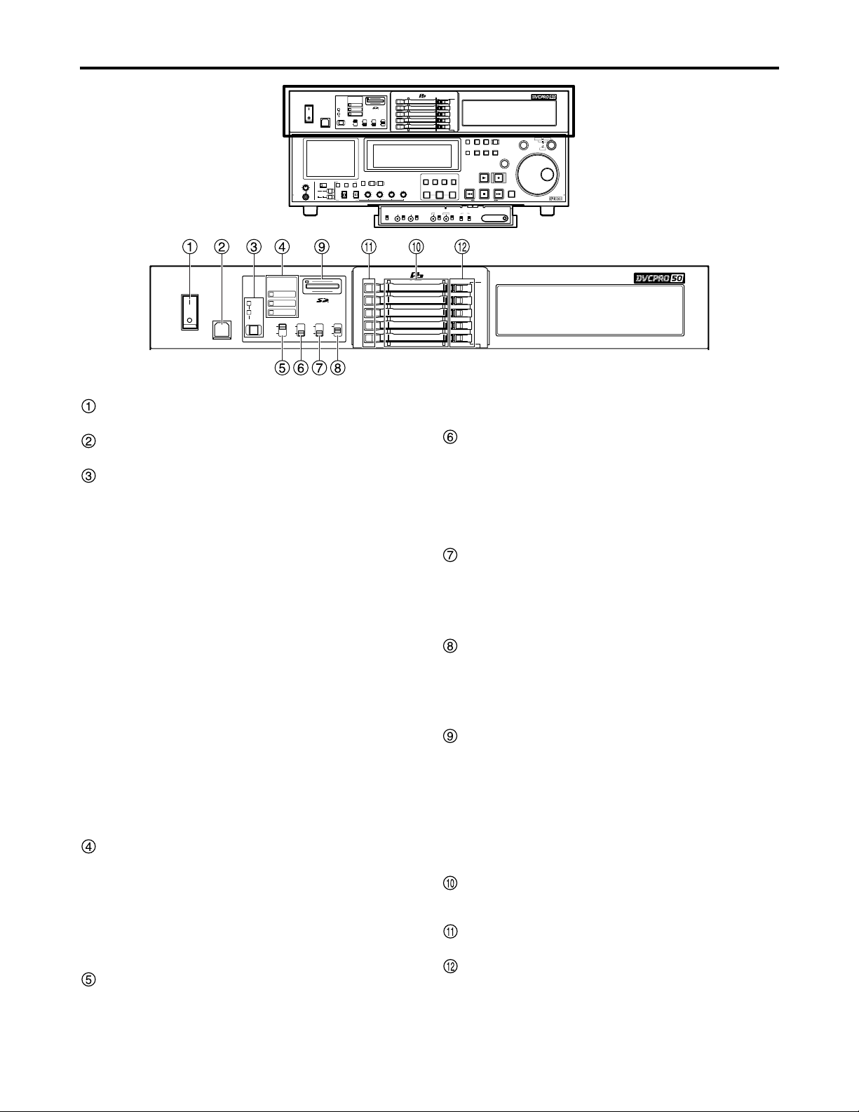
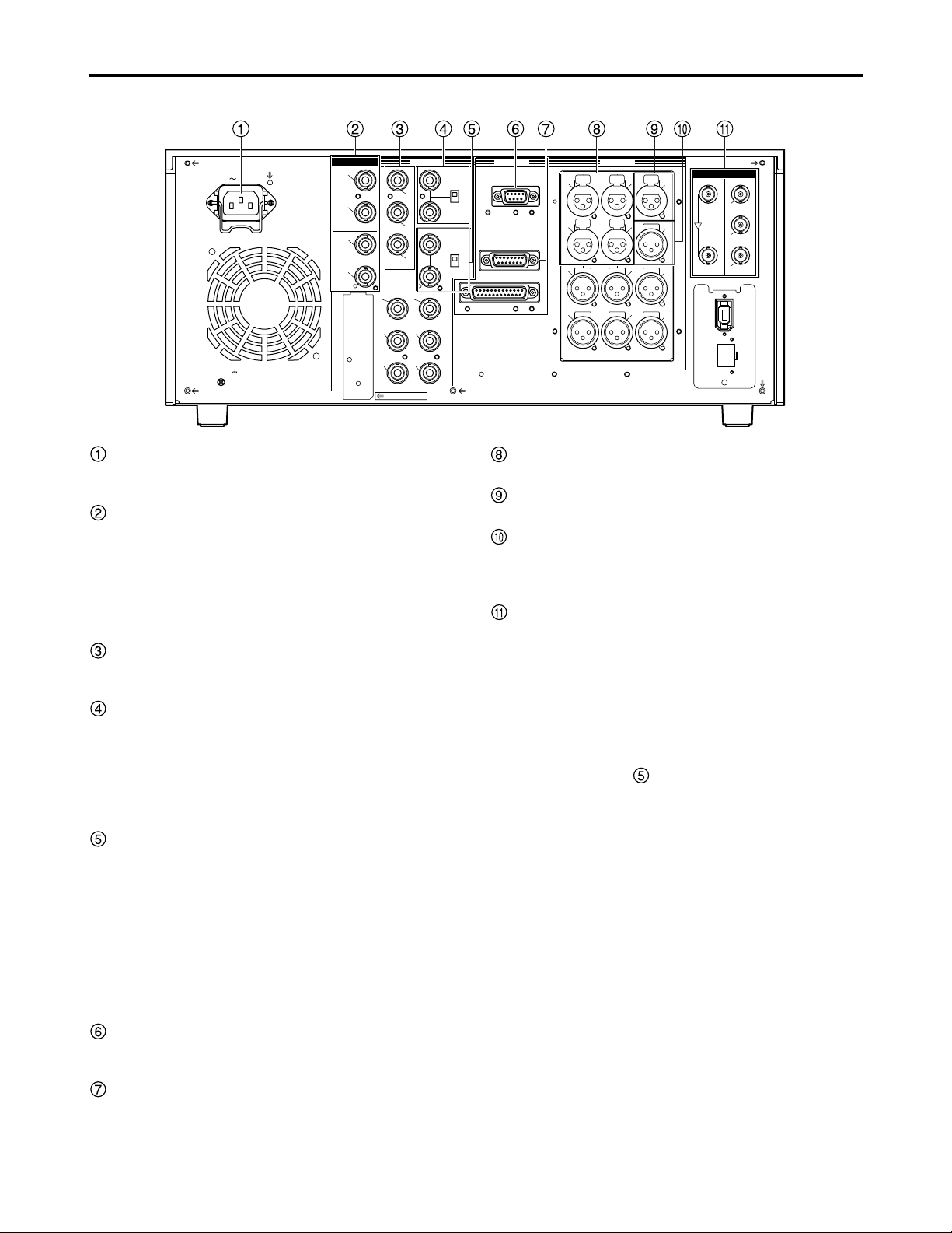
POWER switch
Use when switching between ON and OFF of the power.
USB 2.0 connector (Type B)
Use when connecting a personal computer (See page 20).
REMOTE button and REMOTE display
Use when operating the memory card recorder under
external control or copying files on P2 cards through the
9-pin REMOTE, RS-232C, LAN, or USB 2.0 terminal.
When the REMOTE button is pressed, the REMOTE
display changes as follows: [Lights out]
→
[REMOTE
lights]
→
[Lights out]. When it is pressed while holding
down the SHIFT button, the displays change as follows:
[Lights out/REMOTE lights]
→
[LAN lights] →[USB
lights]
→
[Lights out]. (These operations are not
performed while thumbnails or play lists are displayed.)
REMOTE button lights:
You can operate the memory card recorder under
external control set at setup menu No. 201 (9P SEL)
or No. 204 (RS232C SEL).
→
LAN lights:
You can check files on P2 cards with a personal
computer on the network through 100BASE-TX
/10BASE-T connection. At this time, front panel
controls of the memory card recorder are disabled.
USB lights:
By connecting a personal computer with USB2.0, you
can use the P2 cards in the memory card recorder as
mass storage. At this time, front panel controls of the
memory card recorder are disabled. You will need to
install the USB driver onto your computer.
Format display area
Shows the recording format and the format of the files
recorded on the P2 card.
DVCPRO50 : This indicates recording and playback of
DVCPRO50 (50 Mbps) format.
DVCPRO : This indicates recording and playback of
DVCPRO (25 Mbps) format.
DV : This indicates recording and playback of
DV format.
SUPER switch
ON :
The time code and other superimposed information
are output to the VIDEO OUT 3 connector, and when
the SDI OUT 3 connector (optional) is provided, they
are output to this connector as well.
OFF: The superimposed information is not output.
REC INH switch
This switch is used to enable or disable recording to P2
cards.
ON : Recording is disabled (inhibited).
The REC INH lamp lights on the display panel.
OFF: Recording is enabled so long as the write-protect
switch mechanism on the card is set to enable
recording.
TCG switch
INT : The internal time code generator is used.
EXT: The external time code which is input from the
time code input connector or video signal VITC is
used. Select at setup menu No. 505 (EXT TC
SEL).
MODE switch
This switch is used to select the signals in the stop
mode.
PB : The signal from the card is output.
EE : The input signal selected by the INPUT SELECT
button is output.
SD memory card slot
Insert an SD memory card.
Insert : With the label facing up and the cut-corner
facing in, press until the card locks in place.
Eject : After checking that the lamp has gone off, press
the card in to release the lock.
Note:
Insert only SD memory cards: do not insert any other
type of cards.
P2 card slots
Press the card in until the eject button pops out. After
inserting the card, push the button over (See page 18).
P2 card access LEDs
See page 19.
EJECT buttons
Press to eject the card. Raise the button and press
firmly.
Do not use this button while the card’s access indicator
is on (See page 18).
ON POWER
OFF
USB 2.0
REMOTE
DVCPRO 50
USB
DVCPRO
LAN
DV
SUPER
TCG
REC INH
ON
INT
ON
OFF
EXT
OFF
1
2
3
MODE
PB
4
EE
5
Page 11

11
Control reference guide (continued)
Front panel
— Under section (1/3)
3.5-inch color LCD monitor
Use thumbnails and other features to find and check
video and audio.
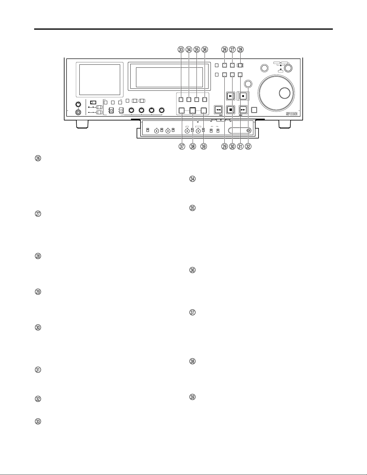
PLAY button
Press to start playback.
Press together with the REC button to start recording.
REC button
Recording starts when this button is pressed in the stop
mode while holding down the PLAY button.
Press this button in the stop mode with the MODE
switch at the PB setting to monitor E-E mode pictures
and audio signals. The original pictures and sound are
restored when the STOP button is pressed.
REW/PREV button
Press to rewind.
Select the speed at setup menu No. 102 (FF. REW
MAX).
Press the REW button while pressing the SHIFT button
with the MODE switch at the PB setting to find the
previous clip . In the case of clips whose data spans a
multiple number of P2 cards, you can find the beginning
of the next card.
1 Regarding the clip:
The clip is a data group that contains video, audio,
and added information and that is created with onetime operation of recording and stop.
Repeating this operation can create two or more
clips.
The picture when starting recording is displayed in
the thumbnail as a typical example of clips.
STOP button
Press to stop. If the MODE switch is set to PB, you can
monitor still pictures.
1
FF/NEXT button
Press to fast forward.
Select the speed at setup menu No. 102 (FF. REW
MAX).
Press the FF button while pressing the SHIFT button
with the MODE switch at the PB setting to find the next
clip and the beginning of the card.
SHIFT button
Press in combination with the FF and REW buttons.
SEARCH button
Press to search.
Set the search dial to the shuttle mode and turn to the
desired position and playback starts at the set speed
after pressing the SEARCH button.
SHTL/SLOW button
Select whether to use the search dial for SHTL or
SLOW.
Each time you press it, the search dial alternates
between SHTL and SLOW.
Search dial
Locate the edit points.
Each time it is pressed, it is set alternatively to the
SHTL/SLOW mode or the JOG mode, and the JOG,
SHTL or SLOW lamp lights.
When the power is turned on, the search dial will not
operate unless it is first returned to the STILL position
(See page 21).
COUNTER button
Each time you press this button, the counter display
changes as follows: [CTL] → [TC] → [UB].
RESET button
Press in the CTL mode to reset the counter to
[0:00:00:00].
Press while holding down the TC PRESET button in the
TC or UB mode to reset the time code generator.
HEADPHONES
PULL PULL
AUDIO MIX
1&2
CH1/3 CH2/4
REC CH1/3
REC CH2/4
3&4
CH1/3 CH2/4
AUDIO MON SEL
AUDIO VOL SEL
LRMIX
RECPBUNITY
VAR
METER
FULL/FINE
INPUT SELECT
VIDEO AUDIO
CH 1 CH 2 CH 3 CH 4
COUNTER
MENU
TC PRESET
SELECT
SLOT
RESET
THUMBNAIL
MARKER
BAR
MENU
SET
SEARCH
RECPLAY
FFREW STOP
PREV NEXT
SHIFT
SHTL
PUSH
JOG
SLOW
Memory Card Recorder AJ-
ENC
CONTROL
REMOTE
LOCAL
VIDEO
LEVEL
PRESET
MANUAL
CHROMA
LEVEL
PRESET
MANUAL
SET UP
PRESET
BLK
MANUAL
HUE
PRESET
CHROMA PH
MANUAL
TC
REGEN
PRESET
REC RUN
FREE RUN
DIAG
ON
POWER
USB 2.0
OFF
REMOTE
LAN
USB
1
2
3
4
5
SUPER
ON
OFF
TCG
INT
EXT
MODE
PB
EE
REC INH
ON
OFF
DVCPRO 50
DVCPRO
DV
PLAY LIST EVENT
INSERT
DELETE
GO TO
ENTRY OUTIN
METER
INPUT SELECT
FULL/FINE
VAR
VIDEO AUDIO
CH 1 CH 2 CH 3 CH 4
ENC
VIDEO
CONTROL
LEVEL
REMOTE
LOCAL
PRESET
MANUAL
CHROMA
LEVEL
PRESET
MANUAL
HEADPHONES
AUDIO MIX
3&4
REC CH1/3
REC CH2/4
AUDIO MON SEL
LRMIX
RECPBUNITY
AUDIO VOL SEL
1&2
PULL PULL
CH1/3 CH2/4
CH1/3 CH2/4
PLAY LIST EVENT
MENU
THUMBNAIL
TC PRESET
MENU
BAR
SLOT
SELECT
MARKER
SEARCH
SHTL
SLOW
PUSH
JOG
SET
RECPLAY
FFREW STOP
SHIFT
Memory Card Recorder AJ-
DIAG
SET UP
COUNTER
RESET
INSERT
GO TO
DELETE
ENTRY OUTIN
PREV NEXT
HUE
PRESET
MANUAL
REGEN
PRESET
TC
REC RUN
FREE RUN
BLK
CHROMA PH
PRESET
MANUAL
Page 12
12
Control reference guide (continued)
Front panel — Under section (2/3)
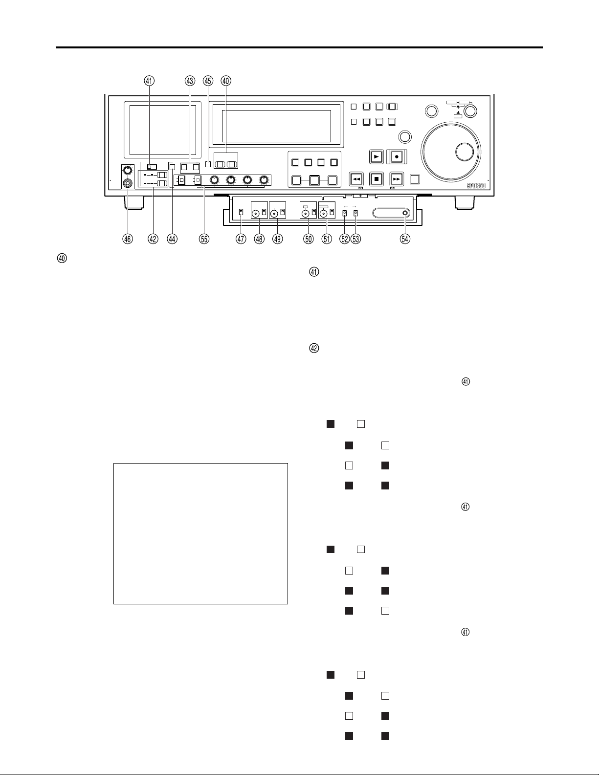
MENU button
Press to show the setup menus on the 3.5-inch color
LCD and the TV monitor (when using the VIDEO OUT 3
or SDI OUT 3 connector (optional)). The setup menu
numbers appear on the memory card recorder’s display
panel.
Press again to exit the setup menu and restore the
original status.
TC PRESET button
Set the TC or UB value (See page 63).
When setting the TC or UB value, press this button first
to stop the data. The set of digits whose display is
flashing is then changed. (However, the button and
display will not function while thumbnails are displayed.)
SLOT SELECT button
In the stop status, use this to set the P2 card on which
the recording is to begin.
Each time you press this button, the numbers of the
slots you can record to appear in order.
THUMBNAIL button
Press this and the button lights and thumbnails appear
on the 3.5-inch color LCD and TV monitor.
Press again to exit the thumbnail screen. The button
also goes dim.
MENU BAR button
When this button is pressed while the thumbnail screen
is displayed, the MENU BAR button lights, and the
pointer that indicates the operation position can be
moved to the menu at the bottom of the display.
Press again to restore the original status.
MARKER button
Press to switch clip markers on and off.
In the thumbnail screen, press to switch on or off the
marker in the clip indicated by the cursor.
SET button
Press to confirm settings in the thumbnail screen, in the
setup menus and when creating play lists.
PLAYLIST button
Press when creating play lists or to play according to a
play list. The button lights and the play list screen
appears on the 3.5-inch color LCD and the TV monitor
(when using the VIDEO OUT 3 or SDI OUT 3 connector
(optional)).
Press again to exit the play list screen. The button goes
off or flashes depending on the status of access to the
clips.
EVENT button
While the PLAYLIST button is lit, press and it lights and
you can enter events (IN and OUT points).
Press again to exit the mode. The button also goes dim.
INSERT/DELETE button
Press to insert or delete play list events.
While a play list is being displayed (the PLAYLIST
button lights), select the event you want to insert and
press this button to insert the event.
While a play list is being displayed (the PLAYLIST
button lights), select the event you want to delete and,
while pressing the SHIFT button, press this button to
delete the event.
GO TO button
Press to move to events in a registered play list.
While a play list is being displayed (the PLAYLIST
button lights), select the event and, while pressing the
IN (or OUT) button, press this button to move the cursor
to the IN (or OUT) point.
IN button
Use when creating play lists.
In the play list creation mode (the PLAYLIST and
EVENT buttons light) press this button together with the
ENTRY button to set the IN point.
Press together with the RESET button to clear an IN
point you have set.
ENTRY button
Use when creating play lists.
In the play list creation mode (the PLAYLIST and
EVENT buttons light) press this button together with the
IN (or OUT) button to set the IN (or OUT) point.
OUT button
Use when creating play lists.
In the play list creation mode (the PLAYLIST and
ENTRY buttons light) press this button together with the
ENTRY button to set the OUT point.
Press together with the RESET button to clear an OUT
point you have set.
METER
INPUT SELECT
FULL/FINE
VAR
VIDEO AUDIO
CH 1 CH 2 CH 3 CH 4
ENC
VIDEO
CONTROL
LEVEL
REMOTE
LOCAL
HEADPHONES
AUDIO MIX
3&4
REC CH1/3
REC CH2/4
AUDIO MON SEL
LRMIX
RECPBUNITY
AUDIO VOL SEL
1&2
PULL PULL
CH1/3 CH2/4
CH1/3 CH2/4
PRESET
MANUAL
CHROMA
LEVEL
PRESET
MANUAL
PLAY LIST EVENT
SET UP
BLK
MENU
THUMBNAIL
TC PRESET
MENU
BAR
SLOT
SELECT
MARKER
SEARCH
SHTL
SLOW
PUSH
JOG
SET
RECPLAY
FFREW STOP
SHIFT
Memory Card Recorder AJ-
DIAG
ENTRY OUTIN
PRESET
MANUAL
INSERT
DELETE
CHROMA PH
GO TO
HUE
PRESET
MANUAL
COUNTER
RESET
PREV NEXT
TC
REGEN
REC RUN
PRESET
FREE RUN
Page 13
13
Control reference guide (continued)
Front panel — Under section (3/3)
INPUT SELECT buttons
Switch the video and audio input signals. You can also
switch the video input signals to the internal signal
selected at setup menu No. 600 (INT SG).
VIDEO:
Each time the VIDEO button is pressed, the input
video signal switches: [Y PB PR] → [CMPST] →
[SDI](optional) → [1394](optional) → [SG
(SG/SG1/SG2)].
When SG is selected, the signal switches to the
internal signal selected at setup menu No. 600 (INT
SG).
AUDIO:
Each time the AUDIO button is pressed, the input
audio signal switches: [ANALOG] → [AES/EBU] →
[USER SET] → [SDI](optional) → [1394](optional) →
[SG].
USER SET enables you to select and record the input
signals separately on PCM audio signal channels 1
through 4. Use in conjunction with the setup menu.
Example:
Notes:
•
You can inhibit input switching (video and audio) of
the INPUT SELECT buttons with setup menus No.
112 (V IN SEL INH) and No. 113 (A IN SEL INH).
•You cannot select SDI and 1394 unless you have
installed the optional board (AJ-YA755G, AJYAD850G).
Settings
AUDIO button
USER SET
Setup menus
No. 715 (CH1 IN SEL): ANA
No. 716 (CH2 IN SEL): DIGI
No. 717 (CH3 IN SEL): DIGI
No. 718 (CH4 IN SEL): ANA
No. 719 (D IN SEL12): AES
No. 720 (D IN SEL34): SIF
PCM audio signals to be recorded on the card
CH1 : Analog input signals
CH2 : AES/EBU digital signals
CH3 : SDI input digital signals
CH4 : Analog input signals
AUDIO MIX switch
Select the audio signals to be recorded to audio
channels CH1/CH2/CH3/CH4.
1&2 : Switch the input to CH1 with REC CH1/CH3.
Switch the input to CH2 with REC CH2/CH4.
3&4 : Switch the input to CH3 with REC CH1/CH3.
Switch the input to CH4 with REC CH2/CH4.
REC CH1/CH3 button and REC CH2/CH4 button
Select the audio signals to be recorded to audio
channels CH1/CH2/CH3/CH4.
When the AUDIO MIX switch is at the [1&2]
setting, the setting is switched by one step in the
sequence of A
→B →
C each time the REC CH1/3
button is pressed.
( ON; OFF)
CH1/3 CH2/4
A The CH1 signals are recorded on
CH1.
B The CH2 signals are recorded on
CH1.
C The CH1+CH2 signals are recorded
on CH1.
When the AUDIO MIX switch is at the [1&2]
setting, the setting is switched by one step in the
sequence of A →B →C each time the REC CH2/4
button is pressed.
( ON; OFF)
CH1/3 CH2/4
A The CH2 signals are recorded on
CH2.
B The CH1+CH2 signals are recorded
on CH2.
C The CH1 signals are recorded on
CH2.
When the AUDIO MIX switch is at the [3&4]
setting, the setting is switched by one step in the
sequence of A →B →C each time the REC CH1/3
button is pressed.
( ON; OFF)
CH1/3 CH2/4
A The CH3 signals are recorded on
CH3.
B The CH4 signals are recorded on
CH3.
C The CH3+CH4 signals are recorded
on CH3.
METER
INPUT SELECT
FULL/FINE
VAR
VIDEO AUDIO
CH 1 CH 2 CH 3 CH 4
ENC
VIDEO
CONTROL
LEVEL
REMOTE
LOCAL
PRESET
MANUAL
CHROMA
LEVEL
PRESET
MANUAL
HEADPHONES
AUDIO MIX
3&4
REC CH1/3
REC CH2/4
AUDIO MON SEL
LRMIX
RECPBUNITY
AUDIO VOL SEL
1&2
PULL PULL
CH1/3 CH2/4
CH1/3 CH2/4
PLAY LIST EVENT
SET UP
BLK
MENU
THUMBNAIL
TC PRESET
MENU
BAR
SLOT
SELECT
MARKER
SEARCH
SHTL
SLOW
PUSH
JOG
SET
RECPLAY
FFREW STOP
SHIFT
Memory Card Recorder AJ-
DIAG
ENTRY OUTIN
PRESET
MANUAL
INSERT
DELETE
CHROMA PH
GO TO
HUE
PRESET
MANUAL
COUNTER
RESET
PREV NEXT
TC
REGEN
REC RUN
PRESET
FREE RUN
Page 14

14
Control reference guide (continued)
When the AUDIO MIX switch is at the [3&4]
setting, the setting is switched by one step in the
sequence of A →B →C each time the REC CH2/4
button is pressed.
( ON; OFF)
CH1/3 CH2/4
A The CH4 signals are recorded on
CH4.
B The CH3+CH4 signals are recorded
on CH4.
C The CH3 signals are recorded on
CH4.
AUDIO MONITOR SELECT (L/R)
Switch the audio signal to be output to the MONITOR
L/R connectors.
Each time you press the L button, the signals output to
the MONITOR L connector switches: [CH1] → [CH2] →
[CH3] → [CH4].
Each time you press the R button, the signals output to
the MONITOR R connector switches: [CH1] → [CH2] →
[CH3] → [CH4].
You can check which signal is currently selected by
seeing which of the L/R lamps in the level meter is lit.
MONITOR MIX button
This button is used to select the mixed signals which are
to be output to the MONITOR L and R connectors.
Each time the MONITOR SELECT L button is pressed
while this button is held down, the signals to be output to
the MONITOR L connector change in the following
sequence: [CH1+CH2] → [CH3+CH4] → [CH1+CH3] →
[CH2+CH4] → mixing release.
The mixed signals to be output to the MONITOR R
connector are changed in the same way by the
MONITOR SELECT R button.
METER (FULL/FINE) selector button
Select the scale display for the audio level meter (See
page 15).
FULL mode:
The standard scale (–∞ to 0 dB).
FINE mode:
Scale in 0.5 dB increments.
“” indicates the standard level of –20 dB (–18 dB),
and each of the dots “” indicates a 1 dB scale
increment.
Headphone jack and volume control
Connect stereo headphones to monitor the sound during
recording or playback.
ENC CONTROL (REMOTE/LOCAL)
Select whether encoder control is to be done on the
memory card recorder or another deck.
REMOTE : Encoder control is done remotely.
LOCAL : Encoder control is done on the memory card
recorder.
VIDEO LEVEL dial and switch
When ENC CONTROL is set to [LOCAL], you can adjust
the video output level.
When set to [PRESET], the video output level is a unity
value (0 dB).
When set to [MANUAL], you can adjust the level with
the dial.
CHROMA LEVEL dial and switch
When ENC CONTROL is set to [LOCAL], you can adjust
the chroma level.
When set to [PRESET], the chroma level is a unity value
(0 dB).
When set to [MANUAL], you can adjust the level with the dial.
SET UP LEVEL dial and switch
When ENC CONTROL is set to [LOCAL], you can adjust
the setup level.
When set to [PRESET], the setup level is a unity value
(0 IRE).
When set to [MANUAL], you can adjust the level with the dial.
HUE LEVEL dial and switch
When ENC CONTROL is set to [LOCAL], you can adjust
the hue.
When set to [PRESET], the hue is a unity value (0 °).
When set to [MANUAL], you can adjust the hue with the dial.
TC REGEN/PRESET switch
REGEN:
The internal time code generator synchronizes with the
time code read by the time code reader from the card.
Select whether to make TC or UB the REGEN in
Setup Menu No. 503 (TCG REGEN).
PRESET:
You can preset with the control panel or remote
control.
TC REC RUN/FREE RUN switch
REC RUN:
The time code runs only while recording.
If REGEN/PRESET is set to [REGEN], the time code
runs constantly.
FREE RUN:
The time code runs when the memory card recorder is
on, irrespective of the operating mode.
DIAG button
Press to show information about the memory card
recorder. Press again to return to the previous display.
(However, the button and display will not function while
thumbnails are displayed.)
The HOURS METER information, WARNING
information and UMID information are shown as the
unit's information.
Press the SEARCH button to switch among the three.
HOURS METER shows the memory card recorder’s
serial number, the number of hours it has been on, and
the number of times it has been switched on and off.
WARNING shows warnings.
AUDIO VOL SEL switches
REC/PB switch
REC: The recording level can be adjusted using the
audio level controls.
PB: The playback level can be adjusted using the
audio level controls.
UNITY/VAR switch
UNITY: The audio signals are recorded and played
back at a fixed level regardless of the positions
of the audio level controls.
VAR: The audio signals are recorded and played back
at the levels adjusted using the audio level
controls.
Audio level controls
Use these to adjust the recording and playback levels
of the audio signals (CH1/CH2/CH3/CH4).
Page 15
15
Control reference guide (continued)
Display
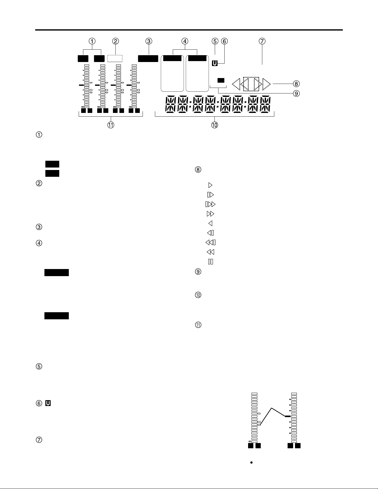
TV system displays
The selected TV system is displayed here.
Switch between 525 interlace and 625 interlace in setup
menu No. 070 (TV SYSTEM) (See page 47).
: lights when 525 interlace TV system is selected.
: lights when 625 interlace TV system is selected.
WIDE lamp
Lights when recording the 16:9 wide-screen information.
You can select the recording of the wide-screen
information using setup menu No. 645 (WIDE SELECT).
During playback, the lamp lights when wide-screen
information has been recorded.
REMOTE lamp
Lights when the CONTROL switch is set to [REMOTE].
INPUT SELECT display area
The indicator for the selected input signal lights. Except
for analog audio signals, the indicator flashes if there is
no input of the selected signal type.
Y PB PR : Analog component video signals
CMPST : Analog composite video signals
SDI : Serial digital video signals (option)
SDTI/1394 : Compressed digital signals (option)
SG/SG 1/SG 2
: Internal reference signals
ANALOG : Analog audio signals
AES/EBU : Digital audio signals
USER SET : Recording audio signal selection
SDI : Serial digital audio signals (option)
SDTI/1394 : Compressed digital signals (option)
SG : Internal reference signals
SCH lamp
Lights when the SCH phase of the external
synchronized signal (REF VIDEO) is inside the
prescribed range.
At all other times, the lamp is off.
lamp
In the E-E mode, this lights when the input signals
contain UMID information.
During playback, it lights when UMID information has
been recorded.
REC and REC INH lamps
REC:
lights when recording.
AUDIO
VIDEO
625
525
REC INH:
Lights when recording is inhibited (the REC INH switch
on the upper front panel is set to [ON] or all the P2
cards are write-protected).
In this status, recording is not possible.
Operation mode displays
The card transport status is displayed here.
: Normal playback or recording
: Playback at a speed slower than 1 x
: Playback at a speed faster than 1 x
: Fast forwarding (FF)
: Reverse playback at 1 x
: Reverse playback at a speed slower than 1 x
: Reverse playback at a speed faster than 1 x
: Rewinding (REW)
: Pause/still
Format displays
The recording format and the format of the card inserted
in the memory card recorder are displayed here.
Counter display
The card counter, time code, etc. are displayed here.
The type of value displayed is indicated by CTL, TC or
UB.
Level meters
These meters indicate the levels of CH1, CH2, CH3,
and CH4 of the PCM audio signals.
During recording or while E-E is selected, the levels of
the audio input signals appear; during playback, the
levels of the audio output signals appear.
Use the METER selector button to switch the audio level
display between FULL and FINE mode (See page 14).
L R
–30
–25
–20
–16
–12
–8
–4
0
–
dB
L R
525 625
REMOTEWIDE
VIDEO
Y PB PR
CMPST
SDI
SDTI/1394
SG 1 2
AUDIO
ANALOG
AES/EBU
USER SET
SDI
SDTI/1394
SG
SCH
DVCPRO
DV
50
REC INH
L R
–30
–25
–20
–16
–12
–8
–4
0
–
dB
L R
–30
–25
–20
–16
–12
–8
–4
0
–
dB
L R
–30
–25
–20
–16
–12
–8
–4
0
–
dB
L R
–30
–25
–20
–16
–12
–8
–4
0
–
dB
CTL
TC
UB
Reference
level
(–20 dB)
(For AJ-SPD850E, reference level: –18 dB)
Each of the dots “” indicates a 1 dB scale increment.
FULL mode FINE mode
For AJ-SPD850P
Page 16
16
Control reference guide (continued)
AC IN
SIGNAL
GND
AES/EBU
CH1•2
IN
CH3•4
IN
CH1•2
OUT
CH3•4
OUT
SDI
IN OUT
1
2
3
(SUPER)
ACTIVE
THROUGH
ANALOG ANALOGREMOTO
Y
VIDEO
IN
P
B
P
R
Y
P
B
P
R
ON
OFF
75Ω
REF VIDEO
IN
ON
OFF
75Ω
1
2
3
(SUPER)
REMOTO IN
ENCODER REMOTE
RS-232C
CH1
CH3
CH1
CH3
CH2
AUDIO
IN
CH4
CH2
CH4
AUDIO
OUT
DVCPRO/
DV
(OPTION)
100BASE-TX
TC
IN
TC
OUT
MON
L
MON
R
SERVICE ONLY
Rear Panel (1/2)
AC IN socket
Connect one end of the power cord supplied to this
socket and the other end to the power outlet.
DIGITAL AUDIO IN and OUT connectors
These are the input and output connectors for digital
audio signals that comply with the AES/EBU standards.
ANALOG COMPONENT VIDEO IN connectors
The analog component video signals are input to these
connectors.
ANALOG COMPOSITE VIDEO IN connectors
and 75 Ω termination switch
Input connectors for analog composite video signals.
A loop-through configuration is featured for each pair of
input connectors.
For termination at the memory card recorder, set the
switch to [ON].
REF VIDEO IN connectors and 75 Ω termination
switch
Input connectors for reference video signals.
Input a reference signal with color burst.
For termination at the memory card recorder, set the
switch to [ON].
Remote control connectors
Connect the memory card recorder to an external
controller.
ENCODER REMOTE connector
Connect the memory card recorder to an external
encoder to adjust video output signal settings from an
external component.
Note:
Video and audio output may be disturbed when the
reference video signal is not input, so use a system
which inputs the reference video signal.
Note:
The digital audio signals must be synchronized with
the video input signals; otherwise noise will be
generated in the audio output signals.
ANALOG AUDIO IN connectors
These are the analog audio input connectors.
TIME CODE IN connector
Use to record an external time code onto the cards.
TIME CODE OUT connector
Outputs the playback time code during playback.
Outputs the time code generated by the internal time
code generator during recording.
SERIAL DIGITAL COMPONENT AUDIO and
VIDEO IN and OUT connectors (optional)
Installing an SDI interface board (optional board AJYA755G) in the memory card recorder enables
input/output of digital component audio/video signals
conforming to the SMPTE259M-C standard.
Video signals containing superimposed information can
be output through the SDI OUT 3 connector.
To turn the superimposed information ON or OFF, use
the SUPER switch on the front panel.
Note:
The digital audio signals must be synchronized with
the video input signals; otherwise noise will be
generated in the audio output signals.
Page 17
17
Control reference guide (continued)
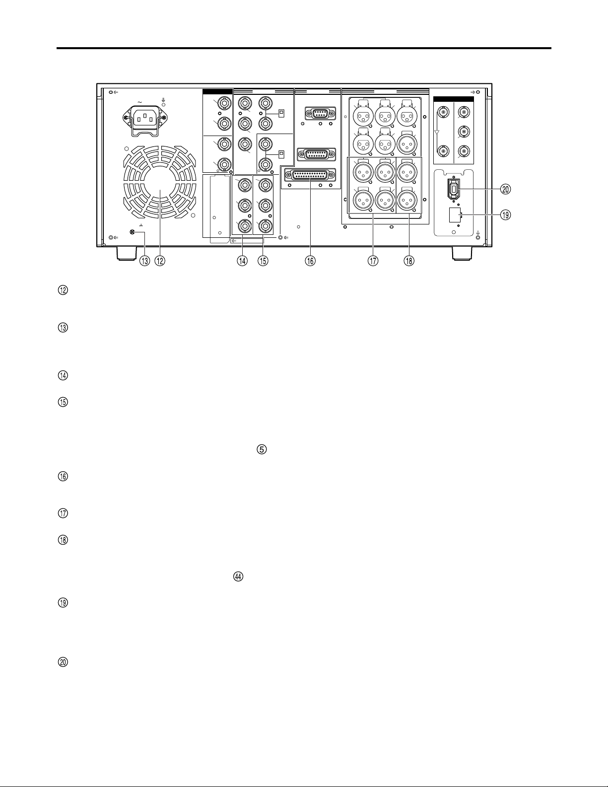
Fan
Cool the memory card recorder.
If the fan stops, “E-10” appears on the counter display.
SIGNAL GND terminal
Connect to the signal ground terminal on the component
connected to the memory card recorder to minimize
noise. It is not a safety ground.
ANALOG COMPONENT VIDEO OUT connectors
Output analog component video signals.
ANALOG COMPOSITE VIDEO OUT connectors
Output analog composite video signals.
Video signals containing superimposed information can
be output through the VIDEO OUT 3 connector.
Switch ON or OFF with the SUPER switch on the
front panel.
RS-232C connector
Connect a personal computer or other component to
control the memory card recorder.
ANALOG AUDIO OUT connectors
Output analog audio signals.
MONITOR OUT connectors
During playback, a mixed signal is output from the
CH1/CH2/CH3/CH4 audio signals. This signal is
switched by the MONITOR MIX button on the front
panel.
LAN connectors
Connect to a network with a 100BASE-TX/10BASE-T.
Note:
Do not remove the P2 cards while the LAN is
connected for use.
Optional connectors
Installing the optional board (AJ-YAD850G) provides an
IEEE1394 interface.
DVCPRO/
DV
(OPTION)
100BASE-TX
AC IN
SIGNAL
GND
AES/EBU
CH1•2
IN
CH3•4
IN
CH1•2
OUT
CH3•4
OUT
SDI
IN OUT
1
2
3
(SUPER)
ACTIVE
THROUGH
ANALOG ANALOGREMOTO
Y
VIDEO
IN
P
B
P
R
Y
P
B
P
R
ON
OFF
75Ω
REF VIDEO
IN
ON
OFF
75Ω
1
2
3
(SUPER)
REMOTO IN
ENCODER REMOTE
RS-232C
CH1
CH3
CH1
CH3
CH2
AUDIO
IN
CH4
CH2
CH4
AUDIO
OUT
TC
IN
TC
OUT
MON
L
MON
R
SERVICE ONLY
Rear Panel (2/2)
Note:
Use shielded cables for all the cables (except for the
AC cable) which are to be connected to the rear
panel.
Use double-shielded cables for connection to the
serial digital signal connectors (DIGITAL AUDIO
IN/OUT and SERIAL DIGITAL COMPONENT
AUDIO VIDEO IN/OUT connectors).
Page 18
18
Recording and playing
Note:
Before using the unit for the first time, be absolutely sure
to set the internal clock using setup menu item No.069
(CLOCK SET).
(1) Turn the POWER switch of the memory card
recorder on
(2) Press a card in a P2 card slot until the EJECT
button pops out
(3) Push the EJECT button that has popped out
over to the right
•When the P2 card is inserted into the memory card
recorder, its status is indicated by the corresponding
P2 card access LED. For details on these statuses,
refer to “P2 card access LEDs and P2 card status.”
•When the REC button and PLAY button are pressed
together in the stop mode, recording starts on the P2
card corresponding to the access LED which has
lighted up orange.
Notes:
• Even when a second P2 card is inserted into
another slot while the data of one card is
playing, its access LED will remain off and
the other P2 card will not be recognized. The
second card will be recognized after the play
of the first card has been completed.
• The P2 card access LED will flash and the
P2 card will be recognized when a P2 card is
inserted into another slot during recording.
Do not remove the P2 card while it is being
recognized.
Inserting P2 cards
EJECT button
Insert the card
with the label
facing up.
P2 card access LED
Do not remove a P2 card while it is being accessed or while
it is being recognized after it has been inserted (while its
corresponding access LED is flashing orange).
(1) Press the STOP button.
If the access LED corresponding to the P2 card you
want to remove is flashing orange, press the STOP
button to make it stop flashing. If the LED does not stop
flashing, hold the STOP button down for over a second.
(2) Raise the EJECT button
(3) Push the EJECT button in to remove the card
Notes:
• When a P2 card is removed while the thumbnail
screen is displayed, the thumbnail screen is
automatically exited.
• Do not remove a P2 card while it is being
accessed or while it is being recognized after it
has been inserted (while its corresponding
access LED is flashing orange). If a P2 card has
been removed while it was being accessed, the
“TURN POWER OFF” display will appear on the
LCD monitor, and the “AUTO OFF” warning will
appear on the display panel. Also, all the P2
card access LEDs will flash rapidly in orange.
Turn off the power, and then turn it back on.
• The data contained on a P2 card which has
been removed while it was being accessed will
not be destroyed, but the clips may become
irregular. Check the clips first, and then fix them
if necessary. (See page 27)
• If a P2 card has been removed while it was
being formatted, no guarantees are made for its
formatting. Turn on the power, and format the
card again.
Removing P2 cards
Page 19
19
Recording and playing (continued)
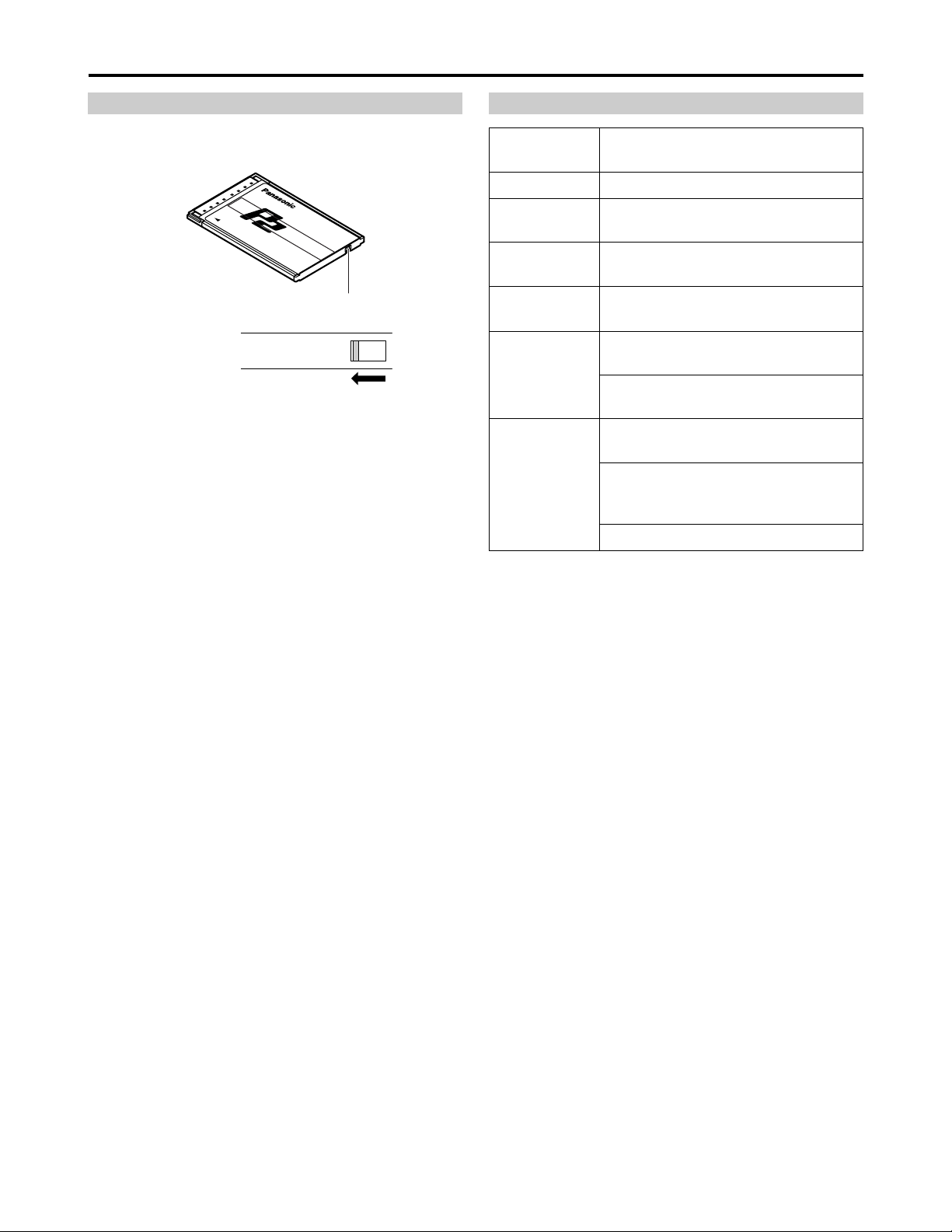
Switch the write-protect switch of the P2 card to
[PROTECT].
Protecting against a possible erasure P2 card access LEDs and P2 card status
PROTECT
Write-protect switch
P2 card status
P2 card
access LED
Recording and play are possible.Green lighting
The memory card recorder is accessing
to record or play.
Orange flashing
Recording and play are possible.
The card is selected for recording.
Orange lighting
The memory card recorder is reading
card information.
Quick orange
flashing
The card has no remaining recording
capacity (play is possible).
Green flashing
The write-protect switch is switched to
PROTECT (play is possible).
The data format on the card is not
standard. Change the card.
Off
The card is not formatted normally.
Format the card again.
No card is inserted.
Note:
The statuses of the P2 cards can be verified in detail.
Refer to “Contents of P2 Card Status Display Settings”
on page 32.
Notes:
•Any attempt to change the position of the write-protect
switch during recording or playback or while the card
data is being accessed will have no effect until the
recording or playback is completed or the card data is
no longer being accessed.
•When the REC INH switch on the upper front panel is
set to [ON], recording onto any of the P2 cards is
inhibited, but it is still possible to format, delete clips and
set shot marks to ON or OFF.
When the write-protect switch on the P2 card is set to
[PROTECT], all write operations including recording,
formatting and clip deletion are inhibited.
Page 20
20
Connections
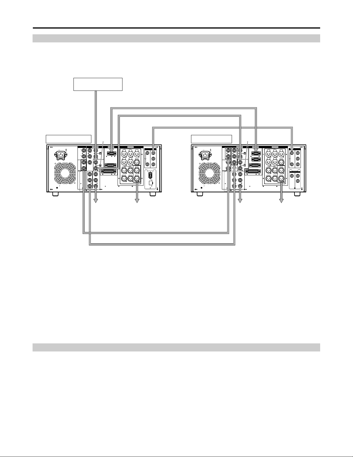
Example of the memory card recorder and DVCPRO VTR
Source machine:
Set the CONTROL switch on the front panel to [REMOTE] (the memory card recorder : AJ-SPD850).
Recorder:
Set the CONTROL switch on the front panel to [LOCAL] (VTR : AJ-SD955 or others).
Notes:
•Video and audio output may be disturbed when the reference video signal is not input, so it is recommended that a
system which inputs the reference video signal be used.
•This unit does not come with color framing settings. Perform the settings for editing using “2F.”
•In terms of the EE output images (including the V BLANK data), the input images are delayed and then output as is. The
menu item settings related to VITC, CC and V BLANK are reflected in the recorded images and playback images but not
in the EE output.
AC IN
SIGNAL
GND
AES/EBU
CH1•2
IN
CH3•4
IN
CH1•2
OUT
CH3•4
OUT
SDI
IN OUT
1
2
3
(SUPER)
ACTIVE
THROUGH
ANALOG ANALOGREMOTO
Y
VIDEO
IN
P
B
P
R
Y
P
B
P
R
ON
OFF
75Ω
REF VIDEO
IN
ON
OFF
75Ω
1
2
3
(SUPER)
REMOTO IN
ENCODER REMOTE
RS-232C
CH1
CH3
CH1
CH3
CH2
AUDIO
IN
CH4
CH2
CH4
AUDIO
OUT
TC
IN
TC
OUT
MON
L
MON
R
SERVICE ONLY
AC IN
SIGNAL
GND
AES/EBU
CH1•2
IN
CH3•4
IN
CH1•2
OUT
CH3•4
OUT
SDI
IN OUT
1
2
3
(SUPER)
ACTIVE
THROUGH
IN OUT
OPUTION
1
2
ANALOG ANALOGREMOTO
Y
VIDEO
IN
P
B
P
R
Y
P
B
P
R
ON
OFF
75Ω
REF VIDEO
IN
ON
OFF
75Ω
1
2
3
(SUPER)
REMOTO IN
REMOTO OUT
ENCODER REMOTE
RS-232C
CH1
CH3
CH1
CH3
CH2
AUDIO
IN
CH4
CH2
CH4
AUDIO
OUT
TC
IN
TC
OUT
MON
L
MON
R
SERVICE ONLY
DVCPRO/
DV
(OPTION)
100BASE-TX
Source machine Recorder
Remote control signal (9 pin)
OFF
With SDI interface board (optional) installed
ON
Digital audio signal
Analog video signal (component)
With analog video input board (optional) installed
To video
monitor device
To audio
monitor device
To video
monitor device
To audio
monitor device
Reference signal
generator
Connection with a PC
1. Connect the USB cable to the USB2.0 connector at the top of the front panel.
Use a cable that supports USB2.0 (one which is shielded and has a ferrite core) for the USB cable.
2. With the unit now connected to the PC, install the P2 software from the accessory CD-ROM into the PC.
For further details, refer to the installation manual.
Notes:
•This unit supports USB2.0 only. It does not support a PC which is compatible with USB1.1.
• Do not remove the P2 cards while the USB is connected for use.
• Except while card data is being accessed, the P2 card access LED remains off while the USB connection is established.
• Use only one deck when making a USB2.0 connection to a PC.
Page 21

21
Jog/Shuttle (Search dial)
(1) Press the search dial so that it remains
pressed in
Check that the JOG lamp lights.
(2) Turn the search dial
The dial’s click-stops are released, and the card data is
played back at the speed (–1x to +1x) corresponding to
the speed at which the dial is turned.
When you stop turning the dial, a still picture is shown.
(3) To transfer the memory card recorder from the
jog mode to another mode, press the button
corresponding to the mode
Note:
The factory setting is that when you turn the search dial
the mode switches to either shuttle mode or jog mode.
Select KEY at setup menu No. 100 (SEARCH ENA), so
the memory card recorder will not transfer to the search
mode unless you press the search button.
Jog mode
(1) Press the search dial so that it is released from
the pressed-in position
The SHTL lamp lights and the shuttle mode is
established.
•Immediately after switching the memory card recorder
on, turn the search dial and leave it at the center
position.
(2) Press the SHTL/SLOW button and switch to
[SHTL] or [SLOW]
(3) Turn the search dial
When the SHTL lamp lights, the playback picture speed
changes from 0 up to ±32x, depending on the dial
position.
This speed can be switched to ±8x, ±16x, ±32x, ±60x or
±100x at setup menu No. 101 (SHTL MAX).
The dial has a click-stop at the center position where the
still picture mode is established.
(4) To transfer the memory card recorder from the
shuttle mode to another mode, press the STOP
button or another button
Notes:
•The playback audio is audible in the –10 to +10x speed
range from the audio monitor output.
•The playback audio heard in the search mode contains
noise.
•When playing a clip that spans a multiple number of P2
cards at a speed faster than ±1x, the sound heard
during play may break up now and then: this is normal
and not indicative of a malfunction.
•When playing back at the –10x speed, the playback
sound may break up: this is normal and not indicative of
a malfunction.
Shuttle mode/Slow mode
Locate the edit points.
Each time it is pressed, it is set alternatively to the SHTL/SLOW mode or the JOG mode, and the JOG, SHTL or SLOW lamp
lights.
When the power is turned on, the search dial will not operate unless it is first returned to the STILL position.
Page 22
22
Working with clip thumbnails
A clip is a piece of data containing video and audio from a single video recording, as well as additional information
such as voice memos and meta-data.
This unit allows the following operations to be performed using the search dial, FF button, REW button, SHIFT
button and SET button while you are checking out the thumbnails of clips displayed on the LCD monitor.
• Playing, deleting, and repairing clips
• Adding/removing shot marks to/from clip thumbnails
• Playing and deleting voice memos
• Formatting P2 cards
• Displaying clip properties and P2 card status
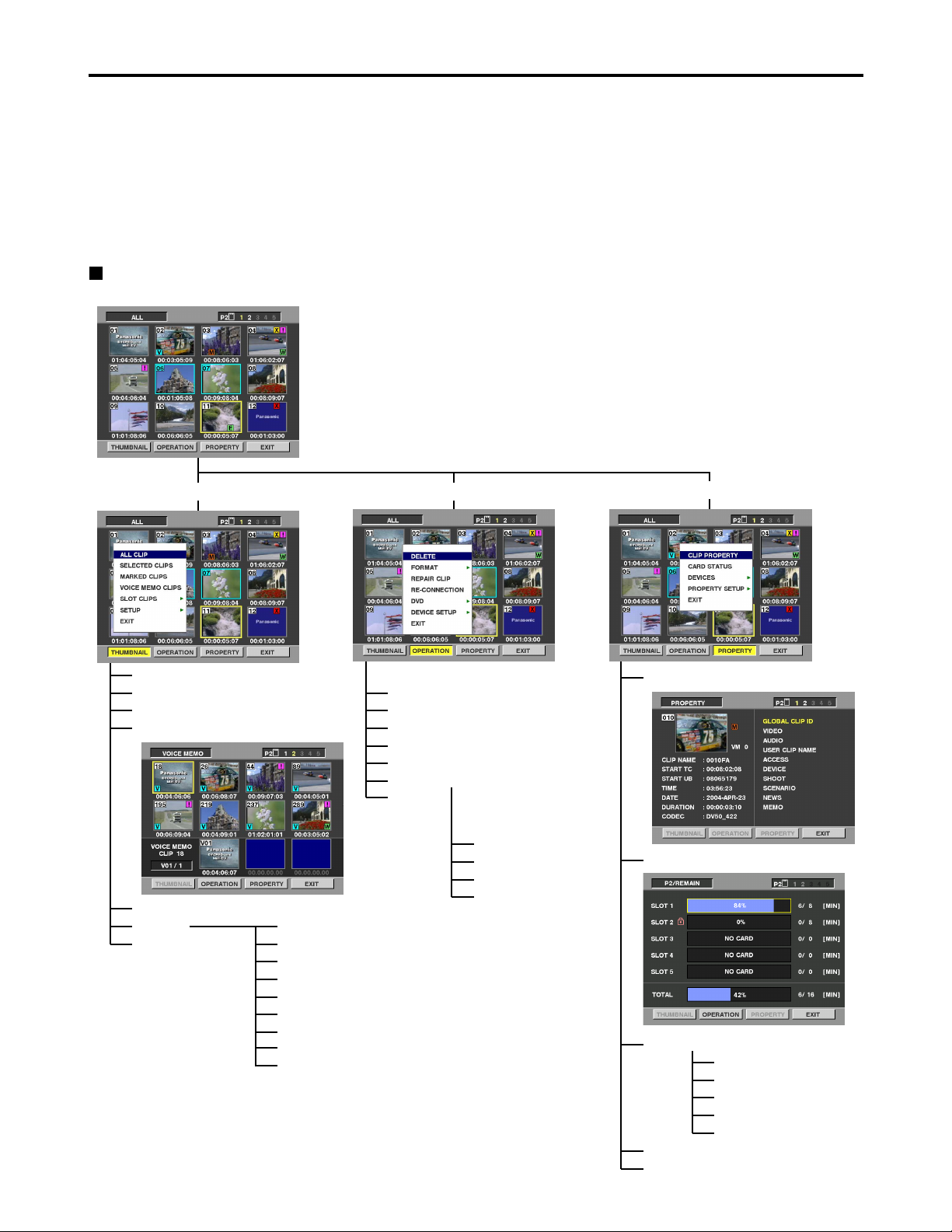
Overview of thumbnail operations
The thumbnail screen is organized as shown below.
THUMBNAIL
ALL CLIP
SELECTED CLIPS
MARKED CLIPS
VOICE MEMO CLIPS
DELETE
FORMAT
REPAIR CLIP
RE-CONNECTION
DVD (optional)
DEVICE SETUP
EXIT
META DATA
NETWORK
DVD (optional)
EXIT
CLIP PROPERTY
CARD STATUS
SLOT CLIPS
SETUP
EXIT
MARKED IND.
VOICEMEMO IND.
WIDE IND.
PROXY IND.
DATA DISPLAY
DATE FORMAT
THUMBNAIL SIZE
THUMBNAIL INIT
EXIT
OPERATION
PROPERTY
DEVICES
PROPERTY SETUP
SD CARD
LAN
META DATA
DVD (optional)
EXIT
Notes:
•While the thumbnail screen is displayed, the
superimposing is not output even if the SUPER switch
has been set to ON.
•The thumbnail screen is output from all the VIDEO OUT
and SDI OUT (optional) connectors in accordance with
the setup menu No.902 (GUI OUTPUT) setting.
EXIT
Page 23
23
Working with clip thumbnails (continued)
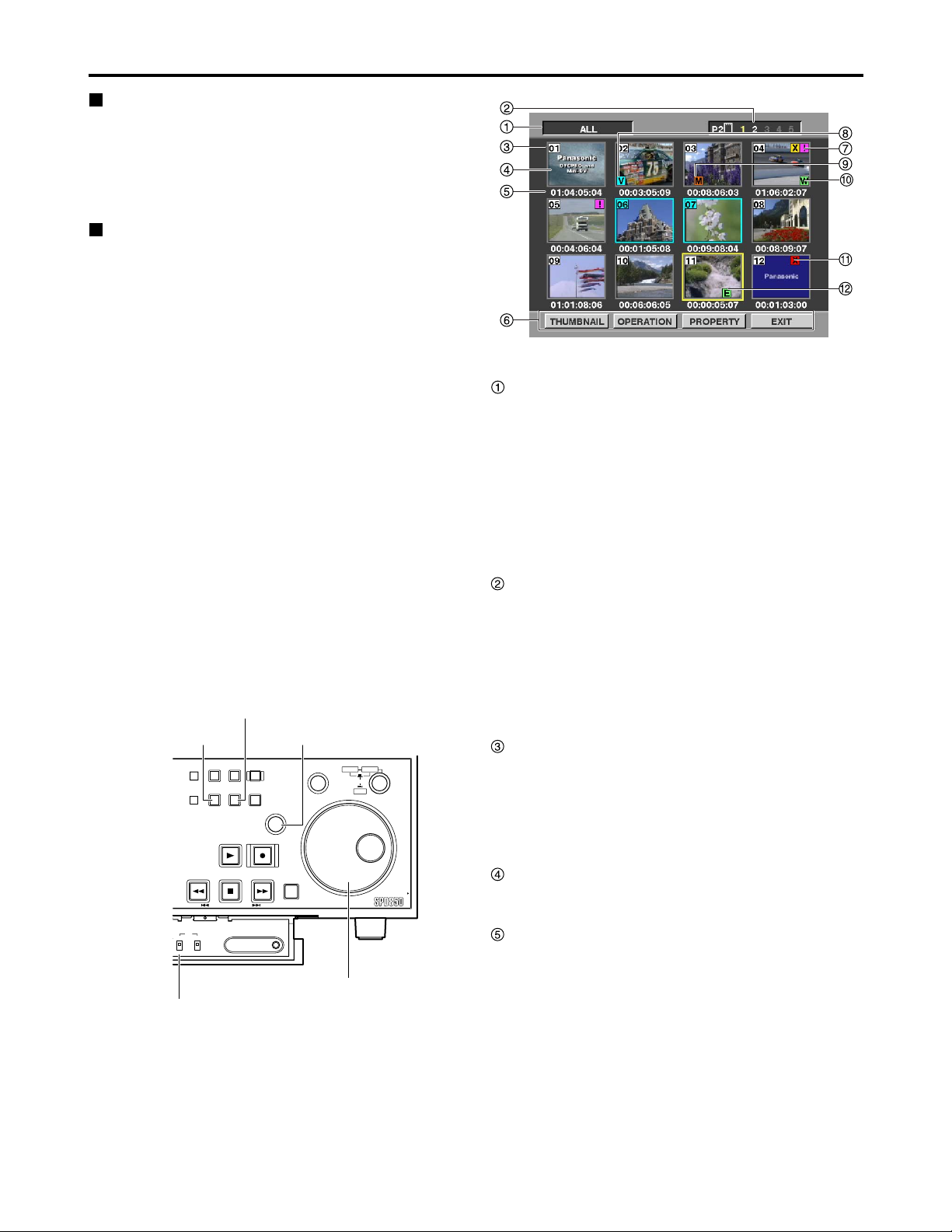
Thumbnail screen
Press the THUMBNAIL button to display the thumbnail
screen on the LCD. Press the THUMBNAIL button again
to return to the normal display.
Press the MENU BAR button on the thumbnail screen to
change the pointer to a menu bar. In this state, menu
actions can be performed on thumbnails.
Thumbnail selection operations
Multiple thumbnails can be selected as desired on the
thumbnail screen.
(1) Use the search dial to move the pointer (yellow
box) to the clip you want to select, and then
press the SET button.
(2) To select more clips, repeat step (1).
When the STOP button is pressed while holding down the
SHIFT button, all the selected clips are released together.
Notes:
•
Turn the search dial clockwise (or press the FF button)
to move the pointer to the right and turn it
counterclockwise (or press the REW button) to move
the pointer to the left. Similarly, turn it clockwise while
holding down the SHIFT button to move the pointer
downward, and turn it counterclockwise while holding
down the SHIFT button to move the pointer upward.
• The pointer moves to the first or last clip when the
REW or FF button is pressed while holding down
the SHIFT button.
• A green box appears around the selected clip
thumbnail. Press the SET button again to deselect
the thumbnail.
•
If, after one clip has been selected, the pointer is
moved to another clip and then the SET button is
pressed while holding down the SHIFT button, all the
clips from the clip selected last to the clip where the
pointer is currently positioned are selected together.
Display status
The display status indicates the type of thumbnails
displayed on the screen.
ALL :All clips are displayed.
SELECTED :Clips selected by the user are displayed.
MARKED :Clips with shot marks are displayed.
VOICE MEMO :Clips containing voice memo data are
displayed.
SLOT :Clips on a specific P2 card are displayed.
For details, see “Switching the thumbnail display” on
page 25.
Slot number
The slot number indicates which P2 card contains the clip
at the pointer location. The slot number of the P2 card
containing the clip recording is displayed in yellow. If a
clip recording is spread across multiple P2 cards, the slot
numbers of all of the P2 cards containing part of the clip
recording are displayed.
In addition, the slot number of the slot where the P2 card
is inserted is displayed in white.
Clip number
Numbers set by the memory card recorder are assigned
to all clips on the P2 card. The numbers are assigned in
chronological sequence, starting with the earliest
recording. Clip numbers for clips with different recording
formats or other clips that cannot be played by the
memory card recorder are displayed in red.
Thumbnail
The first frame in each recorded clip is displayed as a
thumbnail.
Time display
The time display varies depending on the display
settings. It shows the time code at the start of a clip
recording, or the user’s bit at the start of a clip recording,
the recording time, or the recording date.
For details, see “Thumbnail display settings” on page 28.
By default, the time code at the start of a clip recording is
displayed.
Thumbnail screen
Notes:
•Thumbnails operations are not available during time
code or user’s bit settings when the TC
REGEN/PRESET switch is set to PRESET, or during
the access to the setup menu.
•The time taken to display the thumbnails differs
depending on the number of clips recorded on the P2
card. “UPDATING” is displayed on the thumbnail
screen until the thumbnails are displayed.
MENU BAR button
THUMBNAIL button
COUNTER
MENU
RESET
THUMBNAIL
PREV NEXT
TC
REGEN
REC RUN
PRESET
FREE RUN
TC REGEN/PRESET switch
TC PRESET
MENU
BAR
SLOT
SELECT
MARKER
SET button
SEARCH
SET
RECPLAY
FFREW STOP
SHIFT
Memory Card Recorder AJ-
DIAG
Search dial
SHTL
SLOW
PUSH
JOG
PULL
Page 24

24
Working with clip thumbnails (continued)
Menu bar
The menu bar contains menu items for performing clip
operations, switching/setting the thumbnail display, etc.
To use the menu bar, press the MENU BAR button on
the thumbnail screen. Menu items are selected with the
search dial, FF button, REW button or SET button.
THUMBNAIL :This menu is used to switch the
thumbnail display or set the display
method.
OPERATION :This menu is used to delete clips and
format P2 cards.
PROPERTY :This menu is used to display clip
properties and P2 card statuses.
EXIT :This menu is used to return the pointer to
the thumbnail area.
Instead of pressing EXIT, the STOP button can be
pressed while holding down the SHIFT button to return
the pointer to the thumbnail.
Incomplete clip indicator
Regardless of whether a recording extends over a
multiple number of P2 cards, this appears when none of
these P2 cards are inserted into the P2 card slots.
Voice memo indicator
This marker is displayed on clips containing a voice
memo. For details, see “Voice memos” on page 26.
Shot mark indicator
This marker is displayed on clips in which a shot mark
has been added to the thumbnail.For details, on shot
marks see “Shot marks” on page 25.
Wide indicator
This marker is displayed on clips recorded with a 16:9
aspect ratio.
Bad clip indicator
This marker is displayed on clips which were improperly
recorded because, for example, the power was cut off
during recording.It may be possible to repair clips for
which the yellow bad clip indicators were displayed. For
details, see “Repairing clips” on page 27. Clips which
contain red bad clip indicators cannot be repaired, so
they should be deleted. If a clip cannot be deleted,
format the P2 card. appears instead of when the
clips have different formats, etc.
Edit copy clip indicator
This marker is displayed on edit-copied clips.
Indicator for clips with proxy
This marker is displayed for clips with proxy attached.
P
E
X?
X
W
M
V
!
Playing clips
(1) Press the THUMBNAIL button.
The thumbnail screen is displayed on the LCD.
(2) Use the search dial to move the pointer to the
clip you want to play.
The pointer can also be moved to the left by pressing the
REW button and to the right by pressing the FF button.
The pointer moves to the first or last clip when the REW
or FF button is pressed while holding down the SHIFT
button.
(3) Press the PLAY button.
The clip at the pointer location is played on the LCD.
After the clip at the cursor location has been played,
subsequent clips are played in the order in which they
were recorded. After the last clip has been played, the
thumbnail screen is displayed again.
It is possible to display and play only the selected clips
on the thumbnail screen. (It is also possible to select
only those clips which satisfy specific conditions, as the
clips to be displayed on the thumbnail screen.) For
details, see “Switching the thumbnail display” on page
25.
Notes:
•Clips with clip numbers displayed in red cannot be
played.
•It is not necessary to select a clip (so that its thumbnail
has a green box around it) in order to play clips.
•If the REW button is pressed while a clip is being
played, the clip is played in reverse. If the FF button is
pressed, the clip is played in fast forward mode.
•If the STOP button is pressed while a clip is being
played, playback is stopped and the thumbnail screen is
displayed again.
•While playback is stopped, the pointer remains on the
thumbnail of the clip which was being played, regardless
of where the pointer was located at the start of playback.
•The images and sound will be disrupted during playback
between clips that have different formats (DVCPRO50,
DVCPRO, DV): This is normal and not indicative of
malfunctioning.
If the THUMBNAIL button is pressed to close the thumbnail
screen, the playback start position will change back to the
clip with the oldest recording time (Clip number 1).
Page 25

25
Working with clip thumbnails (continued)
Switching the thumbnail display
It is possible to switch the thumbnail screen so that only
clips meeting certain conditions are displayed.
(1) Press the THUMBNAIL button.
The thumbnail screen is displayed on the LCD.
(2) Press the MENU BAR button.
The pointer moves to the menu bar.
(3) Move the pointer to THUMBNAIL, and then
press the SET button to select it.
A submenu is displayed. Select one of the submenu
options to switch the thumbnail display.
ALL CLIP:
All clips are displayed.
SELECTED CLIPS:
Clips selected by the user are displayed.
MARKED CLIPS:
Clips with shot marks are displayed.
VOICE MEMO CLIPS:
Clips containing voice memo data are displayed.
SLOT CLIPS:
Clips recorded on a P2 card inserted in a specific slot
are displayed. When this option is selected, another
submenu is displayed, presenting SLOT1 through
SLOT5. Select the slot you want to display.
SETUP:
For details on this option, see “Thumbnail display
settings” on page 28.
EXIT:
Exits the submenu.
S
MENU BAR button
Shot marks
The memory card recorder allows the user to add shot
marks to clip thumbnails in order to distinguish clips from
each other.
(1) Press the THUMBNAIL button.
The thumbnail screen is displayed on the LCD.
(2) Use the search dial, FF button or REW button
to move the pointer to the clip where the shot
mark is to be added.
(3) Press the MARKER button.
A shot mark is added to the clip thumbnail at the pointer
location.
To delete a shot mark, move the pointer to the clip and
press the MARKER button again.
Notes:
•Before adding a shot mark to a clip that spans a multiple
number of P2 cards or deleting a shot mark from such a
clip, make sure that all the P2 clips containing the
recording of the clip are inserted, and then proceed.
•It takes time to add or delete shot marks to edit-copied
clips.
S
MARKER button
Note:
Shot marks can even be added during recording.
MENU
THUMBNAIL
TC PRESET
MENU
BAR
SLOT
SELECT
MARKER
SEARCH
SHTL
SLOW
PUSH
JOG
SET
RECPLAY
FFREW STOP
SHIFT
Memory Card Recorder AJ-
DIAG
PULL
COUNTER
RESET
PREV NEXT
TC
REC RUN
EN
ET
FREE RUN
MENU
THUMBNAIL
TC PRESET
MENU
BAR
SLOT
SELECT
MARKER
SEARCH
SHTL
SLOW
PUSH
JOG
SET
RECPLAY
FFREW STOP
SHIFT
Memory Card Recorder AJ-
DIAG
PULL
COUNTER
RESET
PREV NEXT
TC
EN
REC RUN
ET
FREE RUN
Page 26

26
Working with clip thumbnails (continued)
Voice memos
A voice memo is audio data which is separate from the
original recorded audio and can be added to a clip
independently of the original recorded audio. Voice
memos added using a camera recorder can be played.
Playing voice memos
(1) Press the THUMBNAIL button.
The thumbnail screen is displayed on the LCD.
(2) Press the MENU BAR button.
The pointer moves to the menu bar.
(3) On the menu bar, select [THUMBNAIL], then
select [VOICE MEMO CLIPS].
Clip thumbnails containing voice memos will be
displayed in the top part of the LCD screen. Information
about the voice memo on the clip selected by the pointer
will be displayed in the bottom part of the LCD screen.
Note:
Voice memos cannot be added using this memory
card recorder.
Thumbnail
display
area
The total number of voice memos
added to the clip is indicated here.
Still images associated with
voice memos are displayed here.
The pointer moves.
(4) Move the pointer to the clip containing the
voice memo you want to play, and then press
the SET button.
The pointer moves to the lower part of the LCD screen.
(5) Use the search dial to move the pointer to the
still image associated with the voice memo you
want to play, and then press the SET button.
The voice memo is played.
While playing voice memos, refrain from performing any
operation except STOP.
Press the STOP button to stop a voice memo during
playback.
Deleting voice memos
(1) Perform steps (1) through (4) of “Playing voice
memos” to select a voice memo on a clip.
(2) Move the cursor to the voice memo you want
to delete, and then press the MENU BAR
button.
The pointer moves to the menu bar.
(3) On the menu bar, select [OPERATION], then
[DELETE].
A YES/NO dialog box is displayed.
(4) Use the search dial and SET button to select
YES.
The voice memo is deleted.
Deleting clips
(1) Press the THUMBNAIL button.
The thumbnail screen is displayed on the LCD.
(2) Use the search dial, FF button or REW button
to move the pointer to the clip which is to be
deleted.
(3) Press the SET button to select the clip.
(4) Press the MENU BAR button. On the menu bar,
select [OPERATION], then [DELETE].
The following screen is displayed. The number of clips to
be deleted at this time appears on the screen.
(5) Use the search dial and SET button to select
YES.
The clip or clips are deleted. All selected clips (enclosed
in green boxes) are deleted.
[NOW DELETING...] and the progress are displayed
while the clip or clips are being deleted.
Instead of performing the operations in steps (4), clips
can also be deleted by pressing the INSERT/DELETE
button while holding down the SHIFT button.
Note:
The voice memo audio playback is output to the
HEADPHONES jack and to the monitor output jack.
It is also output through the AUDIO OUT jack.
Page 27

27
Working with clip thumbnails (continued)
Repairing clips
This section describes how to repair bad clips which were
have been damaged for reasons such as a sudden
power outage during recording.
(1) Press the THUMBNAIL button.
The thumbnail screen is displayed on the LCD.
(2) Use the search dial to move the pointer to the
clip you want to repair (if a clip is bad, it has a
bad clip mark on it).
(3) Press the SET button to select the clip.
(4) Press the MENU BAR button. On the menu bar,
select [OPERATION], then [REPAIR CLIP].
A YES/NO dialog box is displayed.
(5) Use the search dial and SET button to select
YES.
Reconnecting incomplete clips
Incomplete clips may result when the individual segments
of a clip recorded across multiple P2 cards (connected
clip) are copied separately for each card, etc. These
incomplete clips can be reconnected into a single clip
(the original connected clip) using the reconnection
function.
(1) Press the THUMBNAIL button.
The thumbnail screen is displayed on the LCD.
(2) Use the search dial and SET button to select
the incomplete clips to be reconnected.
Normally the thumbnails with incomplete clip marks are
displayed in succession.
(3) Press the MENU BAR button. On the menu bar,
select [OPERATION], then [RE-CONNECTION].
A YES/NO dialog box is displayed.
(4) Use the search dial and SET button to select
YES.
Note:
Even when only some of the clips are reconnected,
the incomplete clip marks remain unless all of the
clips comprising the original clip are reconnected.
Note:
Only clips with yellow bad clip indicators can be
repaired. Clips with red bad clip indicators should be
deleted. If these clips cannot be deleted, the P2 card
should be formatted.
Formatting a P2 card
(1) Press the THUMBNAIL button.
The thumbnail screen is displayed on the LCD.
(2) Press the MENU BAR button.
The pointer moves to the menu bar.
(3) On the menu bar, select [OPERATION], then
[FORMAT].
The following screen is displayed.
(4) Select the slot containing the P2 card you want
to format.
The screen shown below is displayed.
If you do not want to format the P2 card, select NO.
(5) Use the search dial and SET button to select
YES.
The selected P2 card will now be formatted.
Formatting an SD memory card
An SD memory card can be formatted by first inserting
the card, following the same procedure as for formatting
P2 cards above, and selecting SD CARD in step (4).
<Cautions in using SD memory cards>
SD memory cards used with the AJ-
SPD850
should
conform to SD standards. Be sure to format cards using
the AJ-
SPD850
. Cards formatted according to SD
standards using PCs or other devices can be used. SD
memory cards with the following capacity (8MB - 2GB)
can be used for the AJ-
SPD850
:
8 MB 16 MB 32 MB 64 MB
128 MB 256 MB 512 MB 1 GB
2 GB
Page 28
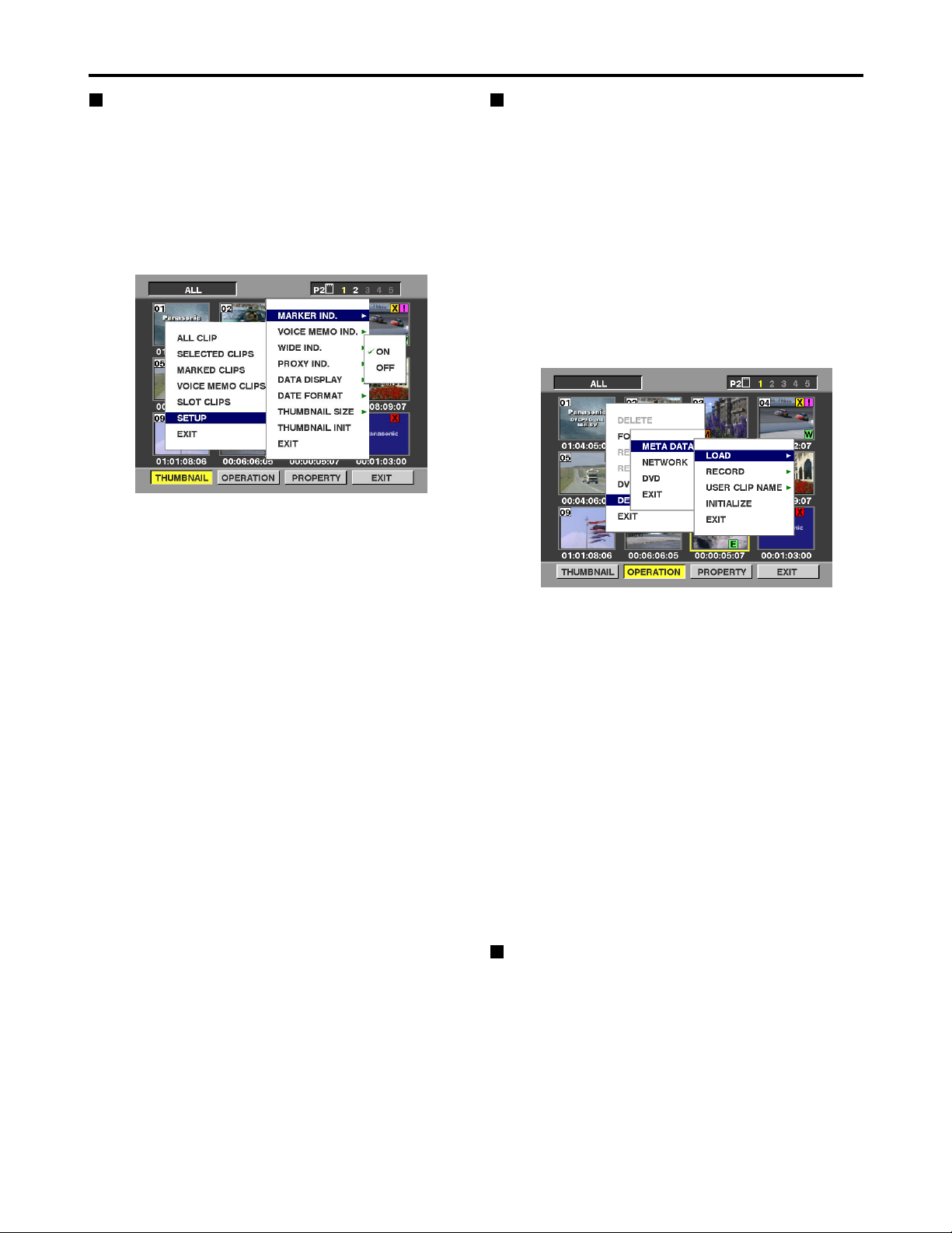
28
Working with clip thumbnails (continued)
Thumbnail display settings
Thumbnail display options can be customized as suitable
for the intended use.
(1) Press the THUMBNAIL button.
The thumbnail screen is displayed on the LCD.
(2) Press the MENU BAR button.
The pointer moves to the menu bar.
(3) On the menu bar, select [THUMBNAIL], then
[SETUP].
The following screen is displayed.
MARKER IND.:
Toggles the shot mark indicator display ON/OFF. The
default setting is display ON.
VOICE MEMO IND.:
Toggles the voice memo indicator display ON/OFF.
The default setting is display ON.
WIDE IND.:
Toggles the wide indicator display ON/OFF. The
default setting is display ON.
PROXY IND.:
Switches the proxy indicator between indication and
no indication (ON/OFF). The factory setting is ON
(indication).
DATA DISPLAY:
The following clip time display options are available:
time code (TC), user’s bit (UB), recording time (TIME),
recording date (DATE) or date/time (DATE TIME). The
default setting is time code.
DATE FORMAT:
The following recording date and time display formats
are available: year month day (YMD), month day year
(MDY), day month year (DMY). The default setting is
year month day (YMD).
This setting applies to the recording date displayed
under clip properties, and the recording date and time
displayed when DATE is selected for DATA DISPLAY.
THUMBNAIL SIZE:
Either LARGE or NORMAL can be selected for the
size of the thumbnails which are to be displayed on
the LCD monitor screen. The factory setting is
NORMAL.
THUMBNAIL INIT:
Return the above thumbnail display settings to default.
Select [THUMBNAIL INIT], and press the SET button.
Select “YES” when the confirmation screen is
displayed.
EXIT:
Returns to the previous menu.
Setting of Clip Meta Data
Information such as the name of person who shot the
video, the name of the reporter, the shooting location, or
a text memo can be read from the SD memory card, and
can be recorded as Clip Meta Data.
<Reading Clip Meta Data (metadata upload)>
(1) Insert the SD memory card that contains the
Clip Meta Data (metadata upload file).
(2) Press the THUMBNAIL button.
The thumbnail screen appears on the LCD monitor.
(3) Press the MENU BAR button.
The cursor moves to the menu bar.
(4) Select [OPERATION] → [DEVICE SETUP] →
[META DATA] → [LOAD] from the menu bar,
and press the SET button.
(5) Names of metadata upload files stored on the
SD memory card are displayed.
Select the desired files using the cursor buttons, and
choose YES. Upload starts.
To check the loaded data, refer to “Confirmation of
Metadata Upload” on page 33.
<To set whether or not the uploaded metadata is
recorded>
Set ON/OFF by selecting [OPERATION] → [DEVICE
SETUP] → [META DATA] → [RECORD] from the menu
bar.
ON:
The metadata is recorded in accordance with the
setting for the USER CLIP NAME recording method.
OFF:
The metadata is not recorded.
Metadata upload files
Using the latest update version of P2 viewer, metadata
upload files can be written to SD memory cards using a
PC. Download the latest update version of P2 viewer
from the following URL and install it to your PC:
http://panasonic.biz/sav/p2
Regarding SD memory cards to be used, see “Cautions
in using SD memory cards” (page 27).
Page 29

29
<Selecting the USER CLIP NAME recording method>
From the menu bar, select [OPERATION] → [DEVICE
SETUP] → [META DATA] → [USER CLIP NAME] item.
Either [TYPE1] or [TYPE2] can be selected as the USER
CLIP NAME recording method.
[TYPE1]
[TYPE2]
1 Concerning the COUNT value
The COUNT value is indicated as a 4-digit number.
When the clip metadata has been loaded and [TYPE2]
has been selected as the recording method, the COUNT
value is incremented by 1 each time a shot is taken and a
new clip is generated.
It can be reset by following the sequence of steps below.
From the menu bar, select [PROPERTY] → [DEVICE] →
[META DATA] and then the [USER CLIP NAME] item.
The window shown below now appears. Align the pointer
with [COUNT RESET] and press the SET button to reset
the COUNT value to 1.
Concerning the incrementing of the COUNT value
of USER CLIP NAME with clips exceeding 4 GB
When a P2 card with a memory capacity of 8 GB or
more is used in this unit, if a one-time continuous
recording exceeds the prescribed duration (refer to the
section on “Dividing clips over 4 GB in length” on page
9) or if a one-time recording extends over more than one
card, the recording concerned will automatically be
undertaken as a separate clip. At this time, the COUNT
value is automatically incremented by 1 and recorded.
Example of recording (DVCPRO50) a clip on one
P2 card:
Example of recording a clip on two P2 cards:
If the clip thumbnails are shown and their properties are
displayed using a P2 series product, the thumbnail and
COUNT value of clip 1 will be displayed.
<Clear the uploaded metadata>
Select [OPERATION] → [DEVICE SETUP] → [META
DATA] → [INITIALIZE] from the menu bar, and press the
SET button. Select “YES” when the confirmation screen
is displayed.
Clip 1/
COUNT value = A
Clip 2/
COUNT value = A + 1
REC start
(recording start)
Stop
(recording stop)
1st card 2nd card
Clip 1/
COUNT value = A
Clip 2/
COUNT value = A + 1
REC start
(recording start)
Recording duration = Approx. 15 min.
Approx. 10 min. Approx. 5 min.
Stop
(recording stop)
Working with clip thumbnails (continued)
When clip metadata has
been loaded
When clip metadata has
not been loaded or a
setting for not recording
the loaded clip metadata
has been selected
USER CLIP NAME to be
recorded
Uploaded data
Same as GLOBAL
CLIP ID (UMID data)
When clip metadata has
been loaded
When clip metadata has
not been loaded or a
setting for not recording
the loaded clip metadata
has been selected
USER CLIP NAME to be
recorded
Uploaded data
+ COUNT value
1
Same as CLIP NAME
Page 30
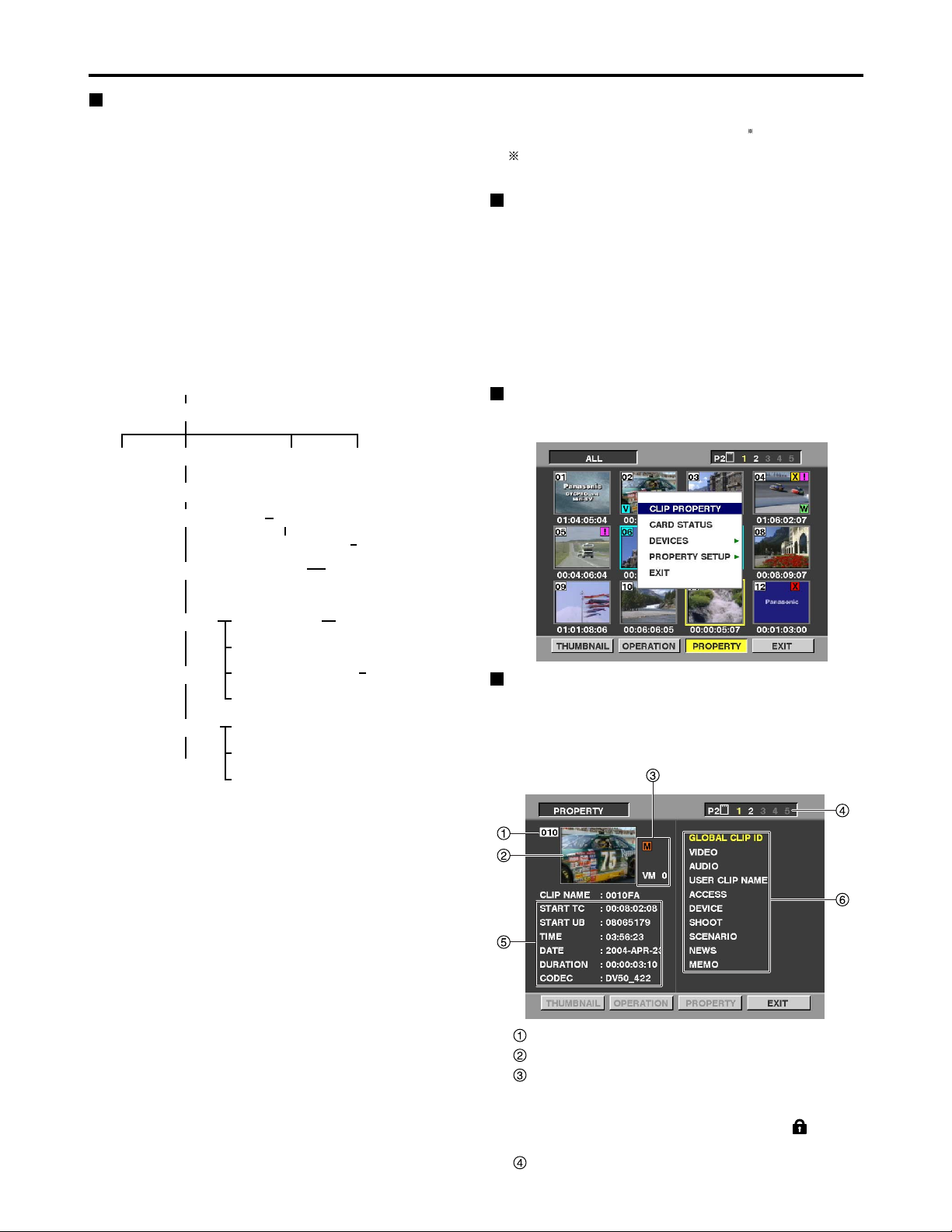
30
Clip number
Thumbnail
Clip information
Various indicators added to the clip, and the number
of added voice memos are displayed. If the P2 card
containing the clip is write-protected, a mark is
also displayed in this area.
Slot number
Working with clip thumbnails (continued)
Example: IP 192.168.000.002
MASK 255.255.255.000
GATE 192.168.000.xxx
“xxx” must be a value which does not exist on the
network connected.
DVD settings (optional)
Set whether to use the DVD drive. When not using the
DVD drive unit, use the initial setting [DISABLE]. Refer to
the operating instructions of the DVD drive unit when
using the DVD drive unit.
Note:
[EXPORT], which is used to save all the clips together in
the DVD, cannot be used when a P2 card with a memory
capacity of 8 GB or more is used.
Displaying the properties
This displays the clip properties, P2 card statuses and
device properties.
Displaying the clip properties
From the menu bar, select [PROPERTY], then [CLIP
PROPERTY] (alternatively, press the GO TO button
while holding down the SHIFT button).
The following screen is displayed.
Network settings
Perform the network settings.
(1) Press the THUMBNAIL button.
The thumbnail screen is displayed on the LCD.
(2)
Press the MENU BAR button, and select the
following from the menu bar: [OPERATION]
→[DEVICE SETUP] → [NETWORK] →[MANUAL].
Then select [IP ADDRESS] →[DHCP ON]/[DHCP
OFF].
If [DHCP OFF] is selected, set IP ADDRESS,
SUBNETMASK and DEFAULT GATEWAY.
(3) Next set [LOCALHOST NAME] and [USER].
(4) Set whether [FTP] is to be used and [SAMBA].
Enter the settings using the search dial and SET button.
Shown below is the device setup configuration.
Notes:
•Data cannot be recorded on the P2 card via the
network.
•As a setting for [LOCALHOST NAME] or [USER NAME],
a letter of the alphabet must always be used as the first
character.
For [LOCALHOST NAME]:
Alphanumerics and “-” can be used for the second and
subsequent characters.
For [USER NAME]:
Alphanumerics, “-” and “.” can be used for the second
and subsequent characters.
•The IP address of [DEFAULT GATEWAY] must be set
without fail even when there is no gateway.
Be absolutely sure to select a value which can be set
from the unit's [IP ADDRESS] and [SUBNET MASK].
[OPERATION]
[DEVICE SETUP]
[NETWORK]
[MANUAL]
[IP ADDRESS]
[DVD] [EXIT]
[LOCALHOST NAME]
[USER]
[NEW USER]
[HOST NAME]
[DELETE USER]
[CHANGE PASSWORD]
[SMB]
[WORK GROUP]
[EXIT]
[EXIT]
[FTP]
[SAMBA]
[EXIT]
[DHCP ON]
[DHCP OFF] [IP ADDRESS] / ···
[USER NAME] / ···
[USER NAME] / ···
[META DATA]
Page 31

31
Working with clip thumbnails (continued)
Clip information
Various clip information is displayed in this area.
START TC: The time code value corresponding to
the start of recording is displayed here.
START UB: The user’s bit value corresponding to
the start of recording is displayed here.
TIME: The time at the start of recording is
displayed here.
DATE: The recording date is displayed here.
DURATION: The clip length is displayed here.
CODEC: The clips recording format is displayed
here.
Clip meta-data
This area shows more detailed information on the
clip. Move the pointer using the search dial, and then
press the SET button to display the detailed
information.
GLOBAL CLIP ID:
The global clip ID is displayed here.
VIDEO:
[FRAME RATE
], [PULL DOWN], [ASPECT RATIO]
= Information on the video signal system, etc. is
displayed here.
AUDIO:
[SAMPLING RATE
], [BITS PER SAMPLE] =
Information on the audio channel systems, etc. is
displayed here.
USER CLIP NAME:
The global clip ID is used as is for the USER CLIP
NAME if there is no information in the metadata
upload file or the [RECORD] item has been set to
[OFF].
ACCESS:
[CREATOR] [CREATION DATE
], [LAST UPDATE
PERSON] = Information on the date of the last
update, etc. is displayed here.
DEVICE:
[MANUFACTURER
], [SERIAL NO.], [MODEL
NAME] = Information on the serial number of the
device which recorded the data, etc. is displayed
here.
SHOOT:
[SHOOTER], [START DATE
], [END DATE],
[LOCATION]: Information on the altitude, longitude,
latitude, source, place name, recording start date,
recording end date, etc. is displayed here.
SCENARIO
1
/NEWS/MEMO2:
[PROGRAM NAME], [SCENE NO.], [TAKE NO.] /
[REPORTER], [PURPOSE], [OBJECT] / [PERSON],
[TEXT] = Information on the program name, scene
number, reporter, subject of the report, etc. is displayed
here.
1 Be sure to enter [PROGRAM NAME] when
entering SCENARIO. It is not possible to record
only the [SCENE NO.] or [TAKE NO.].
2 Be sure to enter [TEXT] when entering MEMO. It
is not possible to record only [PERSON] or
[OFFSET].
The underlined items are automatically added in
accordance with the settings when data is recorded by
this unit.
Each of these items can be input from a PC, etc. Only ASCII
printable characters can be displayed with this memory card
recorder.
Although a multiple number of [TEXT] items can be input
for one clip, only the first TEXT item is displayed with this
memory card recorder.
P2 Card Status Display Settings
Select [PROPERTY] → [CARD STATUS] from the menu
bar to set the desired indication mode (remaining free
space or used memory capacity) for the P2 card status
display.
(1)
Press the THUMBNAIL button.
The thumbnail screen appears on the LCD monitor.
(2)
Press the MENU BAR button.
The pointer moves to the menu bar.
(3) From the menu bar, select [PROPERTY]
→
[PROPERTY SETUP] →[P2 CARD CAP].
The following screen appears. Select the P2 card status
display settings from the [P2 CARD CAP] menu option.
REMAIN:
Show remaining free space on the P2 card as the P2
card status display.
USED:
Show used memory capacity on the P2 card as the
P2 card status display.
Page 32

32
Working with clip thumbnails (continued)
Contents of P2 Card Status Display
Settings
From the menu bar, select [PROPERTY], then [CARD
STATUS]. The following screen is displayed.
When REMAIN has been selected
Write protect mark
If the P2 card containing the clip is write-protected, a
mark is displayed here.
P2 card status (remaining free memory)
The free memory remaining on the P2 card is displayed
here in the form of a bar meter and a percentage value.
As less and less free memory remains, the bar meter
decreases toward the left.
One of the following messages may be displayed
instead, depending on the card status.
FORMAT ERROR
: An unformatted P2 card is inserted in
the slot.
NOT SUPPORTED
: A card which is not supported by the
memory card recorder is inserted.
NO CARD: No P2 card is inserted.
P2 card remaining memory/total memory
This area shows the P2 card’s remaining memory/total
memory. The indicated values are given in minute
increments. Fractions of a minute are rounded off on the
display so that the sum total of the remaining memory
available for recording on each P2 card may not tally with
the figure for the total memory.
Slot remaining free memory total
The figure obtained by totaling the remaining free
memory of the five slots is shown here.
Note that free space on write-protected P2 cards is not
included in the free space total.
When USED has been selected
Write protect mark
If the P2 card containing the clip is write-protected, a
mark is displayed here.
P2 card status (memory used)
The amount of memory used on the P2 card is
displayed here in the form of a bar meter and a
percentage value. As more and more memory is used,
the bar meter increases toward the right. Depending on
the status of the card, one of the following displays may
appear.
FORMAT ERROR
: An unformatted P2 card is
inserted in the slot.
NOT SUPPORTED
: A card which is not supported by the
memory card recorder is inserted.
NO CARD: No P2 card is inserted.
P2 card used memory/total memory
The amount of memory used on the P2 cards and their
total memory capacities are displayed here. The memory
amounts are indicated in minutes. Any amount less than
one minute is rounded off so that the total for the amounts
of memory used for each of the P2 cards and their total
memory capacities may not match. The amount of memory
used for a write-protected P2 card is indicated as 100%.
Total memory used in slots
The figure representing the total memory used by the
cards in the five slots is shown here.
Page 33

33
Working with clip thumbnails (continued)
Displaying the device properties
The statuses of the SD memory card, LAN, metadata and
DVD drive can be checked.
<SD memory card status display>
From the menu bar, select [PROPERTY] → [DEVICES]
→ [SD CARD].
If the format is compatible with SD standards,
the message
“SD STANDARD: SUPPORTED”
is displayed.
If the format is not compatible with SD standards,
the message
“SD STANDARD: NOT SUPPORTED”
is displayed. If this is the case, writing or reading will
not be successful. Format the card with the AJSPD850. For more on formatting SD memory cards,
refer to “Formatting an SD memory card” on page 27.
<LAN status display>
From the menu bar, select [PROPERTY] → [DEVICES]
→ [LAN] to display the LAN-related settings.
<Confirmation of Metadata Upload>
The contents of the metadata upload file that is read from
the SD memory card can be checked.
From the menu bar, select [PROPERTY] → [DEVICES]
→ [META DATA]. The following screen appears.
For more information on each item, refer to “Displaying
the clip properties” on page 30.
The META NAME is the meta data name written in the
meta data upload file, and is not recorded in the clip.
<DVD status display> (optional)
From the menu bar, select [PROPERTY] → [DEVICES]
→ [DVD] to display the information on the media inserted
in the DVD drive, the operating time of the DVD drive and
other information.
Note:
Maintenance must be performed when the operating
time of the DVD drive has exceeded 2,000 hours.
Consult with your dealer.
Page 34

34
Play List
Differences between normal playback and
play list playback
Normal playback
In the example shown below, clips 1-3 are on P2 card 1,
and clips 3-5 are on P2 card 2.
Note:
If a recording is split between two P2 cards, the
segments are labeled as shown below, where clip 3
is split between clip 3-1 and clip3-2. Playback is
continuous from the current position except during
play list playback.
The start of the previous (or next) clip is located
when the REW (or FF) button is pressed while
holding down the SHIFT button, but in the case of a
clip which is split between two cards, the start of
clip3-2 is also located.
Play list playback
Set IN/OUT positions at the locations on the P2 card
which are to be played to create a play list. Next, during
play list playback, just the required segments are played
based on the play list.
P2 Card 1
P2 Card 2
Clip 1 Clip 2 Clip 3-1
Clip 3-2 Clip 4 Clip 5
Current position
Continuous
playback
Continuous playback
P2 Card 1
P2 Card 2
Clip 1 Clip 2 Clip 3-1
Clip 3-2 Clip 4 Clip 5
Continuous playback based on play list
(when executed starting with
event
A)
event A event B
IN OUT IN OUT
IN OUT
event C
event A
event B
event C
Play list playback
Using the play list
Switch and submenu selections
Play list buttons
• PLAYLIST button (self-lighting)
This button is used when creating a play list, and to
play data based on a created play list. When the button
is pressed in the stop mode, a play list is displayed.
The button light remains on while a play list is being
created or played.
• EVENT button (self-lighting)
When the button is pressed while the PLAYLIST button
light is on, the mode changes to play list event
(IN/OUT) setting mode. In this mode, the screen shows
video output, and the IN/OUT point TC and event
number are shown in captions.
• INSERT button
This button is used to add a new event while the play
list summary is displayed. Move the pointer to the
event you want to insert in the play list display
(PLAYLIST button light is on), then press the INSERT
button to add the new event.
• DELETE [SHIFT + INSERT] button
This button is used to delete an event while the play list
summary is displayed. Move the pointer to the event
you want to delete from the play list display (PLAYLIST
button light is on), highlight it using the SET button, and
delete it by pressing this button.
• GO TO button
This button is used to find the IN and OUT points of
individual events registered in the play list. While the
play list is displayed (PLAYLIST button light is on),
select an event and press the GO TO button while
holding down the IN button (or OUT button) to move
the IN point (or OUT point). A still image is shown on
the screen. Further, when the GO TO button is pressed
while holding down the SHIFT button, the selected
event can be moved.
• ENTRY button
This button is used to create a play list event. When
this button and the IN (or OUT) button are pressed at
the same time in play list creation mode (both the
PLAYLIST button and EVENT button lights are on), an
event IN point (or OUT point) can be set.
• IN (OUT) button
This button is used to create a play list event. When
this button and the ENTRY button are pressed at the
same time in play list creation mode (both the
PLAYLIST button and EVENT button lights are on), an
event IN point (or OUT point) can be set. When this
button and the RESET button are pressed at the same
time, the IN point (or OUT point) of the selected event
can be deleted.
The play list function enables only particular parts of the
images and sound recorded on five P2 cards to be selected
and the selected parts to be played in any order using only
the unit by operating the IN, OUT and ENTRY buttons on
the front panel.
Note:
The maximum number of events which can be
registered using this unit is 100.
PLAY LIST EVENT
INSERT
GO TO
DELETE
ENTRY OUTIN
Page 35

35
Play List (continued)
Overview of play list operations
Play lists can be created on the play list screen or event screen. Press the PLAYLIST button to switch to the play list
screen or press the EVENT button to switch to the event screen. On the event screen, you can register or change the IN
and OUT points while viewing the images.
On the play list screen, you can insert and delete events as well as start playing the play lists.
The configuration of [SETTING] [OPERATION] on the menu bar is as follows.
(Play list screen with no events registered yet)
(Play list screen with events already registered)
(Event screen)
Register or change the IN and OUT
points while viewing the images.
Set the SUPER switch to ON before
proceeding.
EVENT button
EVENT button
[SETTING] [REPLACE TC] [REPLACE]
[START TC]
[PLAYLIST ESCAPE]
[ON]
[OFF]
[TC]
[START TC: ]
[OPERATION] [DELETE]
[IMPORT]
[EXPORT]
[EDIT COPY]
[EXIT]
[EXIT]
[ALL EVENT]
[PLAYLIST FILE]
[MEMORY]
[SELECTED CLIP]
[EXIT]
[MEMORY]
[EXIT]
[SLOT1]···
[SLOT5]
[SD CARD]
[EXIT]
[SLOT1]
[SLOT5]
[EXIT]
[SLOT1]····
[OVERWRITE]
[APPEND]
[EXIT]
[SAVE]
[SAVE AS]
[EXIT]
[FILE]select
[OVERWRITE]
[APPEND]
[EXIT]
[FILE]select
[SLOT5]
[SD CARD]
[EXIT]
[SLOT1] ························
[SLOT5]
[SD CARD]
[EXIT]
[DF]
[DF]
For AJ-SPD850P
[NDF]
[ALL MODE]
[PLAYLIST MODE]
Notes:
•While the play list screen is displayed, the superimposing is not output even if the SUPER switch has been set to ON.
•The play list screen is output from all the VIDEO OUT and SDI OUT (optional) connectors.
Page 36

36
Play List (continued)
Creating a play list
Registering events
(1) Press the PLAYLIST button in the stop mode to
switch to the play list screen.
(2) Move to the event number corresponding to the
event you want to register.
The pointer can be moved faster by turning the
search dial while holding down the SHIFT button.
When the REW or FF button is pressed at the same
time while holding down the SHIFT button, the pointer
can be moved to the first event or last event.
(3) Press the EVENT button to switch to the event
creation screen.
(4) Press the IN button and ENTRY button at the
same time at the position where you want to start
the event (PLAY, JOG, SLOW, SHTL, FF, REW,
PREV, NEXT, etc.).
(5) Likewise, press the OUT button and ENTRY
button at the same time at the position where you
want to end the event (PLAY, JOG, SLOW, SHTL,
FF, REW, PREV, NEXT, etc.).
•If the event following the event where the pointer is
positioned has not yet been registered, the automatic
increment function will increment the event number by
one. You may continue with registration if you wish to
do so.
•If a registered event applies to multiple clips, the events
are registered separately.
Working with multiple clips (example)
PLAYLIST button
EVENT button
IN button + ENTRY button
OUT button+ ENTRY button
EVENT button
Flow of operations in creating a play list (registering an event)
•Also when registering a clip whose recording extends
over a multiple number of P2 cards, the clip will be
registered as a separate event where it extends over the
P2 cards like the above.
•The maximum number of events which can be
registered using this unit is 100. Bear in mind that if a
multiple number of events are to be registered with a
single registration and this number exceeds 100, the
events exceeding 100 will not be reflected on the play
list.
(6) To check registration or end registration, press
the EVENT button to return to the play list screen.
• Press the PLAY button to start playback at the
beginning of the current event. The stop mode is
established at an event which has not yet been
registered.
Notes:
•Set the IN and OUT points in such a way that the
DURATION of each event is at least 10 frames.
Otherwise, the events may not be played properly.
•The images and sound will be disrupted during playback
between clips that have different formats (DVCPRO50,
DVCPRO, DV): This is normal and not indicative of
malfunctioning.
Page 37

37
Play List (continued)
Moving events
This button is used to change the sequence of events in
the play list. After selecting the event (or events) to be
moved, operate the search dial to move the pointer to the
place where the event is (or the events are) to be moved.
The event is (or the events are) entered by pressing the
GO TO button while holding down the SHIFT button. A
multiple number of events can also be moved at the
same time.
Moving a play list event
Changing events
On the play list screen, move the pointer to the number of
the event to be changed, and press the EVENT button to
switch to the event screen. Play the images, and press
the IN or OUT + ENTRY buttons to change the IN or OUT
point.
Notes:
•If the changed IN point comes after an already
registered OUT point, the OUT point will be reset.
Conversely, if the changed OUT point comes before
an already registered In point, the start TC of the clip
concerned will be registered at the IN point.
•If the event following the event where the pointer is
positioned has not yet been registered, the pointer
will move to the following event.
•Set the IN and OUT points in such a way that the
DURATION of each event is at least 10 frames.
Otherwise, the events may not be played properly.
Selecting and releasing events
On the play list screen, move the pointer to the event
which is to be selected, and then press the SET button.
The display colors of the selected event are reversed.
Pressing the SET button again will release the selected
event.
If the pointer is moved to another event after selecting an
event and then the SET button is pressed while holding
down the SHIFT button, all the events from the selected
position to the pointer position can be selected together.
When the STOP button is pressed while holding down
the SHIFT button, all the selected events can be
released.
Adding new events
To add a new event on the play list currently displayed,
move the pointer to the event which is shown on the play
list (the PLAYLIST button light is on) and which is to be
inserted, and press the INSERT button. The new event is
now added.
Deleting events
To delete an event on the play list currently displayed,
first move the pointer to the event which is shown on the
play list (the PLAYLIST button light is on) and which is to
to be deleted, and use the SET button to highlight the
event. The event can then be deleted by pressing the
DELETE [SHIFT + INSERT] button.
Resetting play lists
All the play list events can be reset.
Select [OPERATION] → [DELETE] → [ALL EVENT], and
then select [YES]. To cancel the resetting, select [NO]
instead.
All the events of a play list can be reset also by pressing
the RESET button while holding down the SHIFT button.
Deleting play list files
You can delete play list files.
Select [OPERATION] → [DELETE] → [PLAYLIST FILE]
to select the location and filename of the file to be
deleted, and press the DELETE [SHIFT + INSERT]
button.
SET button
Search dial
Page 38

38
Play List (continued)
Importing and storing play lists
Importing play lists from an external source
(1) Press the PLAYLIST button to switch to the play
list screen.
(2) Open the OPERATION sub menu and select
IMPORT.
(3) Select the import destination.
[SLOT1-SLOT5]:
The play list data stored on any of the P2 cards in
slots 1 to 5 is selected.
[SD CARD]:
The play list data stored on the SD memory card is
selected.
[SELECTED CLIPS]:
The clips selected on the thumbnail screen are
turned into play list data.
(4) Select the play list data to be imported.
Select the filename.
(5) Select the import method.
[OVERWRITE]:
The data overwrites the play list which was set prior
to importing.
[APPEND]:
The data is added at the bottom of the play list
which was set prior to importing.
[EXIT]:
Importing is aborted.
(6) Press the SET button.
The importing of the play list data starts.
Exporting play lists [EXPORT]
• Exporting the data to P2 cards [SLOT1-SLOT5]
The play list data is stored in the designated area on the
P2 card in the selected slot.
Select [OPERATION] → [EXPORT] → [MEMORY], and
select the slot with the card on which the data is to be
stored.
• Storing on SD memory card [SD CARD]
The play list data is stored using the designated format
in the designated folder on the SD memory card.
• Storing play list data
[SAVE]:
The data overwrites previously stored data under
the filename which was imported last. [SAVE]
cannot be selected if the file has not been read.
[SAVE AS]:
The data is stored under the filename which is
automatically appended.
•Use an SD memory card which has been formatted
using this unit. (See page 27)
Note:
Bear in mind that if the number of events exceeds
100, the play list data for the events exceeding 100
will not be imported.
Playing the play lists
You can start playing a play list from the event where the
pointer is positioned by pressing the PLAY button while the play
list screen is displayed. If the pointer is moved to event 1 and
the PLAY button is pressed, play list play (playing events which
have been registered in succession) starts from the head of the
list. To stop the play list play, press the STOP button.
During play, it is also possible to set the play TC which
will output a continuous value from the prescribed value.
In this case, however, the original value will be used as
the IEEE1394 or other TC.
The initial value is set and the output TC selected using
[SETTING] on the menu bar.
To play the TC from the prescribed value during play:
• Set the TC replacement mode.
Select [SETTING] → [REPLACE TC] → [REPLACE],
and set [ON].
• Set the initial TC value.
Input the initial TC value by selecting [SETTING] →
[REPLACE TC] → [START TC] → [TC] → [START
TC: ].
For AJ-SPD850P:
• Set [DF] or [NDF] for TC.
Select [START TC] → [DF], and then set [DF] or
[NDF].
Play list edit copy function
“Play list edit copying” refers to turning all the events
registered in succession from event 1 into a single clip.
(1)
Open the OPERATION sub menu, and select EDIT COPY.
(2) Select the edit copy destination.
[SLOT1-SLOT5]:
The edit-copied clips are stored on any of the P2
cards in slots 1 to 5.
(3) Select YES using the search dial and SET button.
Edit copying now starts.
•
If the amount of free memory space on the P2 card serving
as the edit copy destination is less than the size of the clip
to be edit-copied, “WARNING: LACK OF REC CAPACITY”
appears, and edit copy does not commence.
• Edit copying is aborted by pressing the SET button or
STOP button at any point during edit copying.
Notes:
• The format of the edit-copied clip is the same as
the format of the events prior to edit copying.
• When clips with shot marks added are included in
an event, the shot marks will also be added to the
edit-copied clips.
• During edit copying, the approximate progress of
the operation is indicated.
• When the beginning of an edit-copied clip is
searched, the beginnings of the events prior to
edit copying are searched.
• During edit copying, information other than the
shot mark is not copied.
Notes:
•Bear in mind that if the event where the pointer is
positioned has not been registered, it cannot be
played on the play list.
•To play the play list, insert all the P2 cards whose
events have been registered on the play list.
Otherwise, the play list will not be played properly.
•When any operation other than playback is
performed during playback in the TC replacement
mode, the TC will be restored to its original value.
•
Events registered in a play list are identified by the P2 card
serial number, etc. Therefore, clips copied to a different P2
card are not recognized as clips for that play list.
Page 39

39
Play List (continued)
List of shortcuts
Selecting the mode in which to access clips
in the normal mode (the mode where the
playlist function has been exited)
The method used to access the clips in the normal mode
can be changed.
Set this to use the playlist you have created as material
for the player in the editing system which employs the
RS-422A interface.
(1) Press the PLAYLIST button to switch to the play
list screen.
(2) Open the SETTING sub-menu, and select
PLAYLIST ESCAPE.
(3) Select the mode to be used to access the clips in
the normal mode.
[ALL MODE]:
All the clips can be accessed.
[PLAYLIST MODE]:
Only those clips registered in the play list mode can
be accessed.
(4) Press the SET button, and then press the
PLAYLIST button.
Operation returns to the normal mode.
Notes:
•Although clips can be played in the play list mode
while replacing them with a continuous TC value
using the [REPLACE TC] setting, the original values
will be retained for the TC values played back in the
PLAYLIST mode while in the normal mode.
•When [PLAYLIST MODE] is selected as the mode in
which to access clips in the normal mode, an asterisk
(
∗
) appears in front of the operation mode on the
superimposed display, and the PLAYLIST button on
the front panel flashes.
•When the power is turned off, [ALL MODE] is set
automatically.
•When [PLAYLIST MODE] is set, the setup menu
cannot be opened.
While thumbnails are displayed
While play lists are displayed
1 You can select any of the clips in the following
range: from the clip (or event) last selected to the
clip (or event) where the cursor is now positioned.
Front panel operation
[SHIFT] + [STOP]
[SHIFT] + [SET]
[SHIFT] + [DELETE]
[SHIFT] + [REW]
[SHIFT] + [FF]
[SHIFT] + [GOTO]
Description
Deselect
Cancel operation
(return to top)
Select multiple clips
1
Delete selected clip(s)
Jump to first clip
Jump to last clip
Display clip properties
Front panel operation
[SHIFT] + [STOP]
[SHIFT] + [SET]
[SHIFT] + [RESET]
[SHIFT] + [DELETE]
[SHIFT] + [REW]
[SHIFT] + [FF]
[SHIFT] + [GOTO]
Description
Deselect
Select multiple events
1
Delete entire play list
Delete selected event(s)
Jump to first event
Jump to last event
Move play list
Page 40

40
Setup (Initial settings)
The memory card recorder’s main settings are performed while making selections using a system of menus.
If a TV monitor has been connected to the VIDEO OUT 3 connector or SDI OUT 3 connector (optional) on the rear
panel and the SUPER switch is set to [ON], the setting menus are displayed on the TV monitor.
HEADPHONES
PULL PULL
AUDIO MIX
1&2
CH1/3 CH2/4
REC CH1/3
REC CH2/4
3&4
CH1/3 CH2/4
AUDIO MON SEL
AUDIO VOL SEL
LRMIX
RECPBUNITY
VAR
METER
FULL/FINE
INPUT SELECT
VIDEO AUDIO
CH 1 CH 2 CH 3 CH 4
COUNTER
MENU
TC PRESET
SELECT
SLOT
RESET
THUMBNAIL
MARKER
BAR
MENU
SET
SEARCH
RECPLAY
FFREW STOP
PREV NEXT
SHIFT
SHTL
PUSH
JOG
SLOW
Memory Card Recorder AJ-
ENC
CONTROL
REMOTE
LOCAL
VIDEO
LEVEL
PRESET
MANUAL
CHROMA
LEVEL
PRESET
MANUAL
SET UP
PRESET
BLK
MANUAL
HUE
PRESET
CHROMA PH
MANUAL
TC
REGEN
PRESET
REC RUN
FREE RUN
DIAG
ON
POWER
USB 2.0
OFF
REMOTE
LAN
USB
1
2
3
4
5
SUPER
ON
OFF
TCG
INT
EXT
MODE
PB
EE
REC INH
ON
OFF
DVCPRO 50
DVCPRO
DV
PLAY LIST EVENT
INSERT
DELETE
GO TO
ENTRY OUTIN
(1)
(6) (4) (2)
(3)
Changing the settings
(1) Press the MENU button
The setup menu screen appears on the TV monitor, and
the setup menu item number appears on the counter
display.
Each time the FF button is pressed (for about 1.5
seconds), the item number and item name are displayed
alternately.
(If a setup was performed previously, the screen on
which the last change was made is displayed.)
(2) Turn the search dial to select the item to be set
The menu screen cursor ( ) moves, and the item
number on the display flashes.
•When the dial is turned clockwise, the item number is
incremented from 001 → 002 → 003 → 004 and so on;
conversely, when it is turned counterclockwise, the
item number is decremented.
•When the FF button or REW button is pressed while
holding down the PLAY button, the next or previous
item is selected.
•Whenever possible, limit the use of the search dial to
the JOG mode.
(3) At the position where the change is to be
made, turn the search dial while holding down
the SEARCH button
The settings on the menu screen and display now flash.
When the dial is turned clockwise, the setting number is
incremented; conversely, when it is turned
counterclockwise, it is decremented.
(4) Upon completion of the setting, release the
SEARCH button
•When the search dial is in the SHTL mode, the item will
move unless the dial is set to the center position.
(5) When other items are to be changed, repeat
steps (2) to (4)
(6) Press the SET button
The changes are stored in the memory.
To disregard the new settings and restore the old settings
instead, press the MENU button.
•To return the setup contents to the factory settings
(initial settings), press the RESET button while the menu
is displayed. The following message is displayed.
If the PLAY button is now pressed, the factory settings
are reinstated.
SETUP - MENU INIT SET
YES<PLAY> / NO<STOP>
Notes:
•If the RESET button is pressed to restore the factory
settings, only the user files currently in use are
restored. The other user files remain unaffected.
•The changes made to the SYSTEM menu contents
are recorded even by pressing the MENU button to
close the menu screen.
SUPER switch (set to [ON])
Page 41
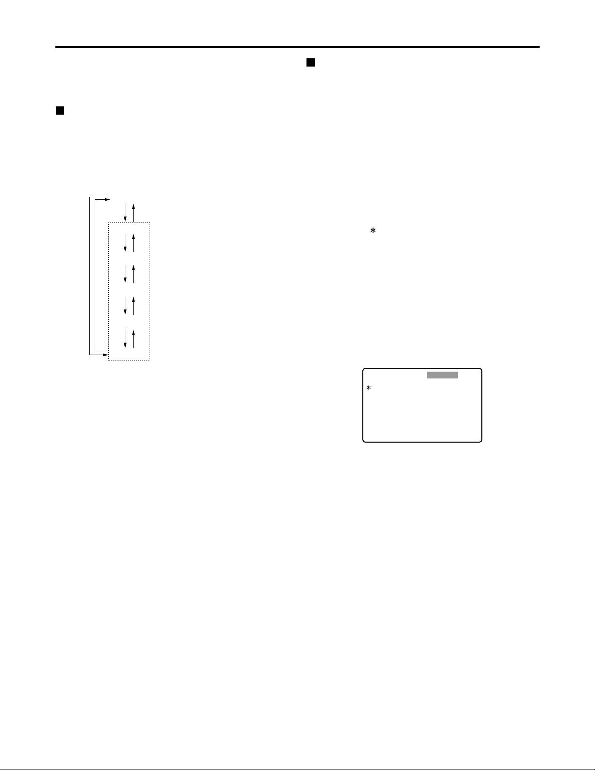
41
Setup menus
The memory card recorder can hold five user files, each of
which has its own specific menu settings, and one of these
files can be selected for use.
Changing the file
(1) Press the MENU button
(2) Press the FF button while holding down the
DIAG (or SHIFT) button to switch to the next
user file or press the REW button while holding
down the DIAG (or SHIFT) button to return to
the previous user file
Setting and releasing the lock mode
The lock mode can be set to protect the system file and
user file (USER2 to USER5) settings. Once the lock
mode is set, no further changes can be made to the
settings.
Setting and releasing the lock mode can be set for the
system file by using setup menu No. 40 (MENU LOCK)
and for the user files by using setup menu No.A03
(MENU LOCK).
(1) Press the MENU button
(2) Press the REW or FF button while holding
down the DIAG (or SHIFT) button and select the
file for which the lock mode is to be set or
released
(3) Turn the search dial
The cursor ( ) on the menu screen is moved to No. 40
(MENU LOCK) for the system file or to No. A03 (MENU
LOCK) for a user file.
(4) Turn the search dial while holding down the
SEARCH button to select whether the lock
mode is to be set or released
To set the lock mode:
Set 0001 (ON) as the setting.
To release the lock mode:
Set 0000 (OFF) as the setting.
When the lock mode has been set, “LOCKED” flashes
on the menu screen. The counter display stops flashing
and remains lighted.
(3) To enter the selection made in step (2) for the
user file which is to be used, press the SET
button
The user file is changed and stored in the memory.
Note:
Since the SYSTEM menu items are not included in user
files 1 through 5, first select the user file and switch to the
SYSTEM file, and then set the SYSTEM menu items.
SYSTEM
USER 1
USER 2
USER 3
USER 4
USER 5
FFFFREW
REW
FF REW
FF REW
FF REW
FF REW
User files
Each user file contains the
following items.
• BASIC
• OPERATION
• INTERFACE
• EDIT
• TIME CODE
• VIDEO
• AUDIO
• V BLANK
• LCD
• MENU
SETUP-MENU
<USER2>
000
001
002
003
008
009
010
011
012
P-ROLL TIME
LOCAL ENA
CTL DISP
REMAIN SEL
DISPLAY SEL
CHARA H-POS
CHARA V-POS
CHARA TYPE
SYS FORMAT
5s
STOP
±12h
2L
T&STA
4
18
WHITE
50M
NO .000-0005
LOCKED
(5) Press the SET button
The setting is stored in the memory.
Notes:
• The lock mode cannot be set for the USER1 file.
•Once set to the lock mode, a file cannot be reset to the
factory settings even by pressing the RESET button.
Page 42

42
Setup menus (continued)
Loading user files
The contents of the USER2, USER3, USER4 or USER5
file can be copied (loaded) into the USER1 file. Also, the
contents of the USER1 file can be copied (saved) into the
USER2, USER3, USER4 or USER5 file.
(1) Press the MENU button
(2) Press the REW or FF button while holding
down the DIAG (or SHIFT) button and select
USER1 file
(3) Turn the search dial to move the cursor ( ) on
the menu screen to No. A00 (LOAD)
USER 1 USER 2
USER 3
USER 4
USER 5
Load/save
Lock mode can be
set
Lock mode can be
set
Lock mode can be
set
Lock mode can be
set
Load/save
Load/save
Load/save
SETUP-MENU
<USER1>
902
A00
A01
A02
END
GUI OUTPUT
LOAD
SAVE
P. ON LOAD
OFF
USER2
USER2
OFF
NO .A00-0000
MENU
SETUP-MENU
<USER1>
902
A00
A01
A02
END
GUI OUTPUT
LOAD
SAVE
P. ON LOAD
OFF
USER2
USER2
OFF
NO .A00-0000
MENU
SETUP-MENU
USER2 USER1 OK?
YES<PLAY>/NO<STOP>
LOAD
(4) Turn the search dial while holding down the
SEARCH button to select the user file whose
contents are to be loaded into USER1
(5) Press the SET button
The following message appears on the menu screen
and counter display.
Counter display
The number of the user file selected in step (4) is
displayed at .
(6) Press the PLAY button
The settings of the user file selected in step (4) are
loaded, and the USER1 menu display appears. If the
STOP button is pressed instead, the settings are not
changed, and the USER1 menu display appears.
(7) Turn the search dial to move the cursor ( ) on
the menu screen to a number other than No.
A00 (LOAD) or No. A01 (SAVE)
(8) Press the SET button
The USER1 settings are stored in the memory.
If the USER1 settings are not to be stored in the
memory, do not press the SET button but press the
MENU button instead.
Saving user files
(1) Press the MENU button
(2) Press the REW or FF button while holding
down the DIAG (or SHIFT) button and select
USER1 file
(3) Turn the search dial to move the cursor ( ) on
the menu screen to No. A01 (SAVE)
(4) Turn the search dial while holding down the
SEARCH button to select the user file in which
the contents of USER1 are to be saved
Those user files which have been set to the lock mode
do not appear on the display. If all the user files have
been set to the lock mode, the “LOCKED” display
appears, and the contents of USER1 cannot be saved
into any of the user files.
(5) Press the SET button
The following message appears on the menu screen
and counter display.
SETUP-MENU
USER1 USER2 OK?
YES<PLAY>/NO<STOP>
SAVE
Counter display
The number of the user file selected in step (4) is
displayed at .
(6) Press the PLAY button
The settings of USER1 are saved in the user file
selected in step (4) and stored in the memory. If the
STOP button is pressed instead, the settings are not
changed, and the USER1 menu display appears.
(7) Turn the search dial to move the cursor ( ) on
the menu screen to a number other than No.
A00 (LOAD) or No. A01 (SAVE)
(8) Press the SET button
The USER1 settings are stored in the memory.
If the USER1 settings are not to be stored in the
memory, do not press the SET button but press the
MENU button instead.
Automatically recalling a user file when
turning on the power
If the user file to be loaded is selected in advance using
setup menu No. A02 (P. ON LOAD), the file will be
automatically loaded into USER1 when the power is
turned on.
Menu screen
Menu screen
Page 43

43
Setup menus (continued)
SYSTEM menu
No./Item Description
11
SYS SC COAR.
Coarse adjustment of system phase: 90 ° units
Note:
If setting operation is
performed, the setting
value does not return to
factory (default) setting.
0000
0
0001 90
0002 180
0003 270
12
SYS SC FINE
Fine adjustment of system phase:
Variable range ±45 ° or more
–: Advanced, +: Delayed
Note:
If setting operation is
performed, the setting
value does not return to
factory (default) setting.
0000 –128
::
0128
0
::
0255 127
13
SYS H
System phase adjustment: 74 ns steps
–: Advanced, +: Delayed
Note:
If setting operation is
performed, the setting
value does not return to
factory (default) setting.
0000 –128
::
0128
0
::
0216 127
No./Item Description
14
SCH COARSE
SCH phase adjustment: 90 ° units
(The SC phase changes but the H phase does not change.)
–: Advanced, +: Delayed
0000 0
0001 90
0002 180
0003 270
15
SCH FINE
SCH phase adjustment:
Total variable range: ±45 ° or more
(The SC phase changes but the H phase
does not change.)
–: Advanced, +: Delayed
0000 –32
::
0032
0
::
0064 32
16
AV PHASE
This adjusts the audio output phase
with respect to the video output:
20.8 µs steps
–: The audio output phase is advanced
with respect to the video output.
+: The audio output phase is delayed
with respect to the video output.
0000 –100
::
0100
0
::
0200 100
The underlined items indicates the initial setting.
18
SYS H OFFSET
System phase adjustment.
0000 –3: –13.4 µsec
0001 –2: –8.96 µsec
0002 –1: –4.52 µsec
0003
0 : 0 sec
0004 1 : +4.52 µsec
0005 2 : +8.96 µsec
0006 3 : +13.4 µsec
Note:
If setting operation is performed, the
setting value does not return to factory
(default) setting.
19
SYS SC/H
This sets whether the system phase is
to be adjusted by the memory card
recorder or from the external encoder
remote controller.
0000
REMOTE :
The system phase is adjusted from
the external encoder remote
controller.
0001 LOCAL :
The system phase is adjusted by the
memory card recorder.
Note:
This setting does not take effect when
LOCAL has been selected by the ENC
CONTROL switch on the front panel.
Video output signal adjustments
The video output signal adjustments are made by using the ENC CONTROL switch on the front panel and selecting the
SYSTEM menu item No. 19 (SYS SC/H) settings. A control matrix of the adjustments is shown below.
ENC CONTROL
LOCAL
REMOTE
SYSTEM menu item
19: SYS SC/H
LOCAL
REMOTE
LOCAL
REMOTE
SYSTEM menu item
11: SYS SC COAR.
12: SYS SC FINE
13: SYS H
The memory card recorder
The memory card recorder
External encoder remote controller
Front panel (under section)
VIDEO LEVEL
CHROMA LEVEL
SET UP/BLACK
HUE/CHROMA PHASE
The memory card recorder
External encoder remote controller
Setting Item adjusted
Page 44
44
USER menu <BASIC>
No./Item Description
000
P-ROLL TIME
This sets the preroll time.
The preroll time can be set from 0 to 15
seconds in 1-second increments.
0000 0s
::
0005
5s
::
0015 15s
001
LOCAL ENA
This selects the buttons which can be
operated on the front panel when the
REMOTE button is lit.
0000 DIS :
No buttons can be operated.
0001
STOP :
Only the STOP button can be operated.
0002 ENA :
All buttons can be operated.
002
CTL DISP
This selects the 12 or 24 hour display
for the CTL counter.
0000
±12h : 12 hour display
0001 24h : 24 hour display
003
REMAIN SEL
This selects whether the remaining
time or total time is to be displayed in
the superimposed display of the
VIDEO OUT 3/ SDI OUT 3 connector
(optional) signals.
0000 OFF: No display.
0001 2L :
The remaining time is displayed on
the second line.
0002
1L :
The remaining time is displayed on
the first line.
0003 R/TTL :
The remaining time is displayed on
the first line, and the total time is
displayed in the second line.
Notes:
• When “2L” is selected, the remaining
time is not displayed if “TIME” has been
selected as the setup menu item No.
008 (DISPLAY SEL) setting.
• When “R/TTL” is selected, the total time
is not displayed if “TIME” has been
selected as the setup menu item No.
008 (DISPLAY SEL) setting.
Setup menus (continued)
No./Item Description
30
BRIGHT
This adjusts the brightness of the
LCD monitor on the front panel.
Note:
If setting operation is performed, the
setting value does not return to factory
(default) setting.
0000 –7
::
0007
0
::
0014 7
The underlined items indicates the initial setting.
31
CONTRAST
This adjusts the contrast of the LCD
monitor on the front panel.
Note:
If setting operation is performed, the
setting value does not return to factory
(default) setting.
0000 –7
::
0007
0
::
0014 7
40
MENU LOCK
This selects whether the system file
lock mode is to be engaged or
released.
0000
OFF : The lock is released (file
data can be changed).
0001 ON : The lock is engaged (file
data cannot be changed).
SYSTEM menu
Page 45

45
Setup menus (continued)
USER menu <BASIC>
The underlined items indicates the initial setting.
No./Item Description
008
DISPLAY SEL
This selects what information is to be
provided by the time code and other
superimposed displays output from
the VIDEO OUT 3/SDI OUT 3
connector (optional).
0000 TIME : Data only.
(The data indicates the value for
whichever of CTL, TC or UB currently
selected by the COUNTER button.)
0001
T&STA :
Data and operation status.
0002 T&S&M :
Data, operation status and mode.
0003 T&RT : Data and REC TIME
0004 T&YMD :
Data and REC DATE (year/month/day)
0005 T&MDY :
Data and REC DATE (month/day/year)
0006 T&DMY :
Data and REC DATE (day/month/year)
0007 T&UB :
Data and user bit.
However, when UB has been selected
with the COUNTER button, the time
code is displayed after the user bit.
0008 T&CTL :
Data and CTL data.
However, when CTL has been
selected with the COUNTER button,
the time code is displayed after the
CTL data.
0009 T&T : Data and time code.
0010 VITC:
The time code and user bit recorded
on the card are displayed.
Notes:
• Mode display:
DVCPRO 50 (50 Mbps) = DVCPRO_50,
DVCPRO (25 Mbps) = DVCPRO,
DV = DV
• An error message appears if a warning
or error has occurred when “T&S&M”
has been selected as this setting.
• The recording duration and recording
time and date are displayed when the
DV format applies. The operating
status is displayed instead when the
DVCPRO50 (50 Mbps) or DVCPRO
(25 Mbps) format applies.
No./Item Description
009
CHARA H-POS
This sets the position of the characters
on the horizontal plane for the time
code and other superimposed displays
output from the VIDEO OUT 3/ SDI OUT
3 connector (optional).
Note:
Characters may extend beyond the
edges of the screen.
0000 0
::
0004
4
::
0016 16
010
CHARA V-POS
This sets the position of the characters
on the vertical plane for the time code
and other superimposed displays
output from the VIDEO OUT 3/ SDI OUT
3 connector (optional).
Note:
When the DISPLAY SEL setting causes
characters to extend beyond the edges of
the screen, the setting value is changed so
that the characters are automatically
displayed in a position on the screen.
[625i system]
0000 0
::
0023
23
::
0028 28
[525i system]
0000 0
::
0018
18
::
0022 22
011
CHARA TYPE
This selects the display type for the
superimposed display output from the VIDEO
OUT 3/SDI OUT 3 connector (optional) as well
as for displays such as the setup menu, etc.
0000 WHITE :
White characters against a black
background.
0001 W/OUT :
White characters with a black border.
Page 46

46
Setup menus (continued)
USER menu <BASIC>
The underlined items indicates the initial setting.
No./Item DescriptionNo./Item Description
012
SYS FORMAT
This sets the memory card recorder’s
recording and playback format.
0000
50M :
DVCPRO50 (50 Mbps) is selected.
0001 25M :
DVCPRO (25 Mbps) is selected.
0002 DV :
DV (25 Mbps) is selected.
Note:
The format complies with the setting of
this menu item when the card is ejected.
017
CHARA SIZE
This selects the size of the characters
for the superimposed display output
from the VIDEO OUT 3/SDI OUT 3
connector (optional).
0000
NORMAL : Standard size
0001 LARGE :
4 times larger than the standard size
Note:
When LARGE has been selected, only
time data is displayed, regardless of the
setup menu No.008 (DISPLAY SEL)
setting.
01
MONTH
02
DAY
Sets the month.
Note:
If a nonexistent day is set while setting
Feb, April, June, September, or
November, it is set as the first day of the
following month.
0001
JAN
::
0012 DEC
Sets the day.
Note:
If a nonexistent day is set while setting
Feb, April, June, September, or
November, it is set as the first day of the
following month.
0001
1
::
0031 31
03
HOUR
Sets the hour value.
Set the value based on 24-hour clock
time.
0000
0
::
0023 23
04
MINUTE
Sets the minute value.
0000
0
::
0059 59
069
CLOCK SET
Sub-screen
Sets the internal clock time.
Note:
Press the STOP button to display a subscreen for selecting the line to be
recorded. Press the STOP button again
to return from the sub-screen.
00
YEAR
Sets the year.
0000 2000
::
0004
2004
::
0030 2030
Page 47

47
Setup menus (continued)
USER menu <BASIC>
No./Item Description
05
TIME ZONE
Sets the time difference from the
world standard time.
Refer to the table below, and select the
setting which corresponds to the local
time.
0000
00:00
0001 +00:30
0002 +01:00
::
0050 –00:30
No./Item Description
070
TV SYSTEM
This selects the TV system.
0000:
The 525 interlace/59.94 Hz system is
selected.
0001:
The 625 interlace/50 Hz system is
selected.
Notes:
• After this setting is changed, turn off
and back on the power again to take it
effect.
• Analog video signals cannot be
selected using INPUT SELECT once
the TV system has been changed from
the factory setting.
• When the setting is changed, the play
list is reset.
[625i system]
0000 525
0001
625
[525i system]
0000
525
0001 625
Time
City/region
Time
City/region
difference difference
00:00 Greenwich + 13:00
- 00:30 + 10:30
Lord Howe Island
- 01:00 Azores + 12:00 New Zealand
- 01:30 + 09:30 Darwin Islands
- 02:00
Central Atlantic time
+ 11:00 Solomon Islands
- 02:30 + 08:30
- 03:00 Buenos Aires + 10:00 Guam
- 03:30 Newfoundland + 07:30
- 04:00 Halifax + 09:00 Tokyo
- 04:30 + 06:30 Rangoon
- 05:00 New York + 08:00 Beijing
- 05:30 + 05:30 Bombay
- 06:00 Chicago + 07:00 Bangkok
- 06:30 + 04:30 Kabul
- 07:00 Denver + 06:00 Dacca
- 07:30 + 03:30 Teheran
- 08:00 Los Angeles + 05:00 Islamabad
- 08:30 + 02:30
- 09:00 Alaska + 04:00 Abu Dhabi
- 09:30
Marquesas Islands
+ 01:30
- 10:00 Hawaii + 03:00 Moscow
- 10:30 + 00:30
- 11:00 Midway Islands + 02:00 Eastern Europe
- 11:30 + 12:45
Chatham Islands
- 12:00 Kwajalein Atoll + 01:00 Central Europe
+ 11:30 Norfolk Islands
Note:
The clock has an accuracy equivalent to a monthly error
of ±30 seconds with the power OFF. When the precise
time is required, check the time and reset it while the
power is ON.
Page 48
48
Setup menus (continued)
The underlined items indicates the initial setting.
No./Item Description
100
SEARCH ENA
This selects the direct search dial
operation.
0000
DIAL :
For direct search dial operations.
0001 KEY :
Operation is not transferred to the
search mode unless the search button
is pressed.
101
SHTL MAX
This sets the maximum speed for
shuttle operations.
0000 x8 : 8x normal speed
0001 x16 : 16x normal speed
0002
x32 : 32x normal speed
0003 x60 : 60x normal speed
0004 x100 : 100x normal speed
104
REF ALARM
This selects whether to warn the
operator when the REF. VIDEO signal
has not been connected.
0000 OFF :
Warning is not given.
0001
ON :
Warning is given by the flashing
STOP lamp.
Note:
Video and audio output may be disturbed
when the reference video signal is not
input, so it is recommended that a
system which inputs the reference video
signal be used.
102
FF. REW MAX
This sets the maximum speed for FF
and REW operations.
0000 x32 : 32x normal speed
0001 x60 : 60x normal speed
0002
x100 : 100x normal speed
USER menu <OPERATION>
No./Item Description
105
AUTO EE SEL
This selects the memory card
recorder mode in which the EE status
is established when the MODE switch
is set to EE.
0000 S/F/R :
EE status is established in STOP, FF
and REW modes.
However, EE status is established at
all times when the card is ejected,
regardless of the MODE switch
setting.
0001
STOP :
EE status is established in STOP
mode.
However, EE status is established at
all times when the card is ejected,
regardless of the MODE switch
setting.
0002 BLACK :
EE status is established in STOP
mode.
However, when the card is ejected, if
the MODE switch is set to;
EE: EE status is established.
PB: The picture becomes black and
the sound is muted.
0003 BLACK1 :
EE status is established in STOP, FF
and REW modes.
However, when the card is ejected, if
the MODE switch is set to;
EE: EE status is established.
PB: The picture becomes black and
the sound is muted.
0004 GRAY :
EE status is established in STOP
mode.
However, when the card is ejected, if
the MODE switch is set to;
EE: EE status is established.
PB: The picture becomes gray and
the sound is muted.
0005 GRAY1 :
EE status is established in STOP, FF
and REW modes.
However, when the card is ejected, if
the MODE switch is set to;
EE: EE status is established.
PB: The picture becomes gray and
the sound is muted.
Page 49

49
Setup menus (continued)
No./Item Description
USER menu <OPERATION>
113
A IN SEL INH
This selects whether audio input
switching using the INPUT SELECT
button is to be enabled or disabled.
0000 OFF :
Audio input switching using the INPUT
SELECT button is enabled.
0001 ON :
Audio input switching using the INPUT
SELECT button is disabled.
0002
REC :
Audio input switching using the INPUT
SELECT button after the memory card
recorder has been transferred to a
recording mode is disabled.
Note:
Even when the ON or REC setting is
selected to disable audio input switching
using the INPUT SELECT button, it is
still possible to set the setup menu items
No. 715 (CH1 IN SEL), No. 716 (CH2 IN
SEL), No. 717 (CH3 IN SEL), No. 718
(CH4 IN SEL), No. 719 (D IN SEL12)
and No. 720 (D IN SEL34).
112
V IN SEL INH
This selects whether video input
switching using the INPUT SELECT
button is to be enabled or disabled.
0000 OFF :
Video input switching using the INPUT
SELECT button is enabled.
0001 ON :
Video input switching using the INPUT
SELECT button is disabled.
0002
REC :
Video input switching using the INPUT
SELECT button after the memory card
recorder has been transferred to a
recording mode is disabled.
The underlined items indicates the initial setting.
No./Item Description
107
PLAY DELAY
This set the play delay time in frame
increments.
0000
0
::
0015 15
106
EE MODE SEL
This selects the EE mode output
signals.
0000
NORMAL :
Signals are output with a delay
equivalent to the length of internal
signal processing.
0001 THRU :
Signals are output directly, without
internal processing, and so are output
with no delay.
Note:
When 1394 has been selected for the
video input signals or when INT SG has
been selected for video or audio, internal
operations are forcibly set to NORMAL.
Page 50

50
Setup menus (continued)
The underlined items indicates the initial setting.
No./Item Description
USER menu <INTERFACE>
201
9P SEL
This selects whether the REMOTE
(9P) connector functions when the
REMOTE button is lit.
0000 OFF :
Connector does not function.
0001
ON : Connector functions.
204
RS232C SEL
This selects whether the RS-232C
connector functions when the
REMOTE button is lit.
0000
OFF :
Connector does not function.
0001 ON : Connector functions.
205
BAUD RATE
These settings are for selecting the
RS-232C communication speed (baud
rate). (Unit: Bps)
0000 300
0001 600
0002 1200
0003 2400
0004 4800
0005
9600
206
DATA LENGTH
These settings are for selecting the
RS-232C data length. (Unit: bit)
0000 7
0001
8
202
ID SEL
This sets the ID information to be
returned to the controller.
0000 OTHER
0001
DVCPRO
0002 ORIG
Notes:
• ID information of any VTR except for
the DVCPRO’s is set in OTHER.
• Select ORIG only when the unit has
been connected to the specified
controller.
207
STOP BIT
These settings are for selecting the
RS-232C stop bit length. (Unit: bit)
0000
1
0001 2
No./Item Description
208
PARITY
These settings are for selecting the
none, odd or even for the RS-232C
parity bit.
0000
NON :
Parity bit is not used.
0001 ODD:
An odd number of bits is used for the
parity system.
0002 EVEN:
An even number of bits is used for the
parity system.
209
RETURN ACK
These settings are for selecting
whether the ACK code is to be
returned when a command is received
from RS-232C.
0000 OFF : ACK code is not returned.
0001
ON : ACK code is returned.
Page 51

51
Setup menus (continued)
No./Item Description
USER menu <EDIT>
303
STD/NON-STD
This selects STD or NON-STD in
accordance with the composite input
signal.
0000
AUTO :
Standard/non-standard signals are
automatically identified and
processed.
0001 STD :
Standard signals are processed.
(Forced STD)
0002 N-STD :
Non-standard signals are processed.
(Forced NON-STD)
Notes:
• Use the non-standard (NON-STD)
setting when video or audio trouble
occurs with signals from laser discs or a
satellite.
• At the NON-STD setting, the images
shown on the front panel's LCD monitor
will be significantly disrupted when the
unit's operation is transferred from the
play mode to EE mode: this is normal
and not indicative of malfunctioning.
304
REF LOCK
This selects the REF LOCK mode.
0000
AUTO :
Servo is synchronized with the input
signal during recording, or with the
REF signal during playback.
0001 EXT :
Servo is synchronized at all times with
the REF signal.
0002 AUTO1 :
Servo is synchronized with the input
signal during recording, or with the
REF signal during playback.
When there is no reference (REF)
signal, the EE output is synchronized
with the internal reference signal at
the AUTO setting or with the STD
input signal at the AUTO1 setting.
The AUTO1 setting is selected when
the STD signal is to be used.
Note:
At the AUTO setting, the images shown
on the front panel's LCD monitor will be
significantly disrupted when the unit's
operation is transferred from the play
mode to EE mode: this is normal and not
indicative of malfunctioning.
315
AFTER
CUE-UP
This selects the mode after cue-up
operation is complete.
0000
STOP : STOP mode
0001 STILL : SHTL STILL mode
320
VAR FWD MAX
This sets the maximum SLOW FWD
speed.
0000
+4 : +4x speed
0001 +2 : +2x speed
0002 +1 : +1x speed
Note:
At any speed setting other than 0 (+4),
the phase cannot be synchronized from
the editing controller.
321
VAR REV MAX
This sets the maximum SLOW REV
speed.
0000
–4 : –4x speed
0001 –2 : –2x speed
0002 –1 : –1x speed
No./Item Description
323
JOG FWD MAX
This sets the maximum JOG FWD
speed.
0000 +4 : +4x speed
0001 +2 : +2x speed
0002
+1 : +1x speed
Notes:
• The maximum speed is set to +1 x
when the dial on the front panel is
operated.
• At any speed setting other than 0 (+4),
the phase cannot be synchronized from
an editing controller which synchronizes
the phase using the JOG command.
324
JOG REV MAX
This sets the maximum JOG REV
speed.
0000 –4 : –4x speed
0001 –2 : –2x speed
0002
–1 : –1x speed
Note:
The maximum speed is set to –1 x when
the dial on the front panel is operated.
The underlined items indicates the initial setting.
Page 52

52
Setup menus (continued)
No./Item Description
USER menu <TIME CODE>
500
VITC BLANK
This selects whether to output the
VITC signal at the positions selected
by setup menu items No. 501 (VITC
POS-1) and No. 502 (VITC POS-2).
0000 BLANK :
VITC signals are not output.
0001
THRU :
VITC signals are output.
501
VITC POS-1
This sets the position where the VITC
signal is to be inserted.
Note:
The same line as the one used for the
setup menu items No. 502 (VITC POS-2)
and No. 662 (UMID POS) setting cannot
be set.
[625i system]
0000 7L
::
0004
11L
::
0015 22L
[525i system]
0000 10L
::
0006
16L
::
0010 20L
502
VITC POS-2
This sets the position where the VITC
signal is to be inserted.
Note:
The same line as the one used for the
setup menu items No. 501 (VITC POS-1)
and No. 662(UMID POS) setting cannot
be set.
[625i system]
0000 7L
::
0006
13L
::
0015 22L
[525i system]
0000 10L
::
0008
18L
::
0010 20L
503
TCG REGEN
This selects the signal to be
regenerated when the time code
generator (TCG) in the REGEN mode.
0000
TC&UB :
Both the time code and user bit are
regenerated.
0001 TC :
Only the time code is regenerated.
0002 UB :
Only the user bit is regenerated.
505
EXT TC SEL
This selects the time code to be used
when an external time code is to be
used.
0000
LTC :
The LTC of the TIME CODE IN
connector is used.
0001 VITC :
The VITC of the input video signal is used.
Note:
During recording, there is a discrepancy
in the picture and superimposed TC
value displayed, but the actual recording
is not adversely affected in any way.
No./Item Description
506
BINARY GP
This sets the usage status of the user
bit of the time code generated by the
TCG.
0000
000 :
NOT SPECIFIED (character set not
specified)
0001 001 :
ISO CHARACTER (8 bits character
set based on ISO646, ISO2022)
0002 010 : UNASSIGNED 1 (undefined)
0003 011 : UNASSIGNED 2 (undefined)
0004 100 : UNASSIGNED 3 (undefined)
0005 101 : PAGE/LINE
0006 110 : UNASSIGNED 4 (undefined)
0007 111 : UNASSIGNED 5 (undefined)
507
PHASE CORR
This selects whether to control the
phase correction of the LTC which is
output from the TIME CODE OUT
connector.
0000
OFF :
Phase correction control is not
performed.
0001 ON :
Phase correction control is performed.
508
TCG CF FLAG
This selects whether the CF flag of
the TCG is to ON.
0000
OFF : CF flag is OFF.
0001 ON : CF flag is ON.
509
DF MODE
This selects the DF or NDF mode for
CTL and TCG.
0000
DF :
The drop frame mode is used.
0001 NDF :
The non-drop frame mode is used.
Notes:
• Drop frame mode is valid only when the
REMOTE button is lit or the setup menu
No. 001 (LOCAL ENA) is set to ENA.
• This menu option is not displayed in the
625i system.
The underlined items indicates the initial setting.
Page 53

53
Setup menus (continued)
No./Item Description
USER menu <TIME CODE> USER menu <VIDEO>
510
TC OUT REF
This is used to switch the phase of
the time code, which is output from
the TIME CODE OUT connector, for
the external LTC input when the TCG
switch is at the “EXT” position.
0000
V OUT :
Time code is synchronized with output
video signal.
0001 TC_IN :
Time code is synchronized with
external time code input.
511
VITC OUT
This selects how the VITC which is to
be superimposed onto the output
video signal during playback is to be
output.
0000
SBC :
The time code recorded in the sub
code area is output as the VITC.
0001 VAUX :
The time code recorded in the VAUX
area is output as the VITC.
514
VITC GEN
This selects whether or not to record
the internal time code generator value
in the VAUX area.
0000
OFF :
The internal time code generator
value is not recorded in the VAUX
area.
When video signals on which the time
code has been recorded are input, the
time code of the input signals is
recorded in the VAUX area.
0001 ON :
The internal time code generator
value is recorded in the VAUX area.
Note:
If 1394 has been selected as the input
signals, the time code on the input
compressed signals will be recorded
regardless of this menu’s setting.
The underlined items indicates the initial setting.
No./Item Description
600
INT SG
This selects the internal signal.
0001 BB :
The black burst is generated.
0002 CB100 :
100% color bars are generated.
0003
CB75 :
75% color bars are generated.
601
OUT VSYNC
This selects whether to float the
vertical sync position of the video
output in order to align the video
output phase with the input in the
EE/record/edit modes.
0000
N-VF : Signals are not floated.
0001 VF : Signals are floated.
603
CC (F1)
BLANK
This selects ON or OFF for the closed
caption signal of the first field.
0000 BLANK :
Signal is forcibly blanked.
0001
THRU : Signal is not blanked.
Note:
This menu option is not displayed in the
625i system.
604
CC (F2)
BLANK
This selects ON or OFF for the closed
caption signal of the second field.
0000 BLANK :
Signal is forcibly blanked.
0001
THRU : Signal is not blanked.
Note:
This menu option is not displayed in the
625i system.
605
FREEZE SEL
This selects the freeze mode for still
pictures.
0000
FIELD : Field freeze.
0001 FRAME : Frame freeze.
Notes:
• When frame freeze has been selected,
the frame slow status is established
with the slow setting.
• This setting is also followed when there
is a freeze command from the RS-422A
connector, but the picture displayed on
the LCD monitor screen shown at this
time will not be frozen.
606
OUT C KILL
This selects chroma color killer
processing for the video output
signals.
0000 B/W :
No color signals are output.
0001
COLOR :
Color signals are output.
Sub code area:
This area is separate from the video and audio data area on
the P2 card. The time code complying with SMPTE/EBU
standards is stored here.
VAUX area:
This area is to be found in the video data area on the P2 card.
The additional information relating to the video data is
stored here.
Page 54
54
No./Item Description
620
ESR MODE
This selects the operation mode for
edge subcarrier reduction (ESR) in
the playback circuit.
0000 OFF :
The mode is forcibly set to OFF.
0001
AUTO :
The mode is automatically set to ON
or OFF depending on the memory
card recorder operation.
621
CCR MODE
This selects the cross color
processing during playback.
0000
OFF :
The cross color is output with no
changes made.
0001 ON :
The cross color can be reduced.
Note:
This menu option is not displayed in the
625i system.
624
CC REC
This selects whether to record the
closed caption signals multiplexed on
the input signals on the card.
0000
OFF
:
No closed caption signal is recorded.
In addition, the EE output signals are
blanked.
0001 ON :
When a closed caption signal is
detected from the selected input
signal, it can be recorded on the card.
Notes:
• This menu option is not displayed in the
625i system.
• If 1394 has been selected as the input
signals, the closed caption signal on the
input compressed signals will be
recorded regardless of this menu’s
setting.
645
WIDE SELECT
This selects whether to record the
WIDE information on the card.
0001 WIDE :
The information is recorded.
0002
NORMAL :
No information is recorded.
Note:
If 1394 has been selected as the input
signals, the input information will be
recorded.
Setup menus (continued)
USER menu <VIDEO>
No./Item Description
609
EDH
This selects whether to superimpose
EDH onto the SDI output signals.
0000 OFF : EDH is not superimposed.
0001
ON : EDH is superimposed.
Note:
Even when ON is selected for this
setting, EDH is not superimposed onto
the signals output from the SDI OUT 3
connector (optional) if the SUPER switch
on the front panel is set to ON.
610
P
B/PR IN LV
This selects the analog component
input level.
0000 M II : M II level
0001
B-CAM : ß-CAM level
Note:
This menu option is not displayed in the
625i system.
611
YC SEP MODE
This selects Y/C separation
processing for the composite input
signals.
0000 B/W :
The signals are processed as B/W
signals.
0001
AUTO :
The signals are automatically
detected.
614
P
B
/PR OUT LV
This selects the analog component
output level.
0000 M II : M II level
0001
B-CAM : ß-CAM level
Note:
This menu option is not displayed in the
625i system.
The underlined items indicates the initial setting.
618
INTERPOLATE
This selects the interpolation
operation.
Vertical interpolation is conducted
automatically during slow-motion
playback to reduce the vertical
movement of the playback pictures.
However, this menu item enables the
interpolation operation to be forcibly
turned off.
0000 OFF :
Interpolation is forcibly turned off.
0001
AUTO :
Interpolation is automatically turned
on during slow-motion playback.
Page 55
55
Setup menus (continued)
The underlined items indicates the initial setting.
USER menu <VIDEO>
No./Item Description
622
SETUP 25
(For AJ-SPD850P)
Sub-screen
For setting 7.5% setup processing to be
performed on input and output signals
in the DVCPRO (25 Mbps) mode.
When the STOP button is pressed,
operation is transferred to the subscreen, and the setup level is set for
each output. To return from the subscreen, press the STOP button again.
Note:
This setup menu is not displayed in the
625i system.
00
CMPST IN
This selects the 7.5% setup processing
for the input composite signal.
0000 THRU :
The signal is recorded in its original
form.
0001
CUT :
The signal is recorded with the 7.5%
setup removed.
02
CMPNT IN
This selects the 7.5% setup processing
for the input component signal.
0000 THRU :
The signal is recorded in its original form.
0001 CUT :
The signal is recorded with the 7.5%
setup removed.
01
CMPST OUT
This selects the 7.5% setup processing
for the output composite signal.
0000 THRU :
The signal is output in its original form.
0001 ADD :
The signal is output with the 7.5%
setup added.
Note:
Bear in mind the setting for sub-screen
item No. 03 (CMPNT OUT) of setup
menu item No. 622 (SETUP 25).
03
CMPNT OUT
This selects the 7.5% setup processing
for the output composite, component
and serial (digital) signal.
0000 THRU :
The signal is output in its original form.
0001 CUT :
The signal is output with the 7.5%
setup removed.
0002 ADD :
The signal is output with the 7.5%
setup added.
No./Item Description
623
SETUP 50
(For AJ-SPD850P)
Sub-screen
For setting 7.5% setup processing to be
performed on input and output signals
in the DVCPRO50 (50 Mbps) mode.
When the STOP button is pressed,
operation is transferred to the subscreen, and the setup level is set for
each output. To return from the subscreen, press the STOP button again.
Note:
This setup menu is not displayed in the
625i system.
00
CMPST IN
This selects the 7.5% setup processing
for the input composite signal.
0000 THRU :
The signal is recorded in its original
form.
0001
CUT :
The signal is recorded with the 7.5%
setup removed.
02
CMPNT IN
This selects the 7.5% setup processing
for the input component signal.
0000 THRU :
The signal is recorded in its original form.
0001 CUT :
The signal is recorded with the 7.5%
setup removed.
01
CMPST OUT
This selects the 7.5% setup processing
for the output composite signal.
0000 THRU :
The signal is output in its original form.
0001 ADD :
The signal is output with the 7.5%
setup added.
Note:
Bear in mind the setting for sub-screen
item No. 03 (CMPNT OUT) of setup
menu item No. 623 (SETUP 50).
03
CMPNT OUT
This selects the 7.5% setup processing
for the output composite, component
and serial (digital) signal.
0000 THRU :
The signal is output in its original form.
0001 CUT :
The signal is output with the 7.5%
setup removed.
0002 ADD :
The signal is output with the 7.5%
setup added.
Page 56
56
Setup menus (continued)
USER menu <VIDEO>
No./Item Description
660
UMID REC
This selects whether or not to record
the UMID information on the card.
0000 OFF :
UMID information is not recorded on
the card. In addition, EE output
signals are blanked.
0001
ON :
UMID information is recorded on the
card.
Note:
If THRU has been selected as the setup
menu item No. 106 (EE MODE SEL)
setting, UMID information of the EE
output signals will be blanked.
661
UMID GEN
This selects the UMID information to be
recorded on the card when ON has been
selected as the setup menu item No. 660
(UMID REC) setting.
0000 INT :
Newly created UMID information of
this unit is always recorded.
0001
EXT
:
The UMID information of the input
signals is recorded.
Newly created UMID information of
this unit is recorded if there is no
UMID information on the input signals.
662
UMID POS
This sets the line on which the UMID
information is to be superimposed.
Note:
The line selected for the setup menu
item No. 501 (VITC POS-1) and No. 502
(VITC POS-2) settings cannot be
selected for this item.
[625i system]
0000 BLANK
0001 18L
::
0010
17L
::
0015 22L
[525i system]
0000 BLANK
0001 12L
::
0006
17L
::
0008 19L
The underlined items indicates the initial setting.
No./Item Description
USER menu <AUDIO>
701
CH1 IN LV
This selects the audio input (CH1)
reference level switching.
0000 4dB
0001
0dB
0002 –20dB
702
CH2 IN LV
This selects the audio input (CH2)
reference level switching.
0000 4dB
0001
0dB
0002 –20dB
703
CH3 IN LV
This selects the audio input (CH3)
reference level switching.
0000 4dB
0001
0dB
0002 –20dB
704
CH4 IN LV
This selects the audio input (CH4)
reference level switching.
0000 4dB
0001
0dB
0002 –20dB
706
CH1 OUT LV
This selects the audio output (CH1)
reference level switching.
0000 4dB
0001
0dB
0002 –20dB
707
CH2 OUT LV
This selects the audio output (CH2)
reference level switching.
0000 4dB
0001
0dB
0002 –20dB
708
CH3 OUT LV
This selects the audio output (CH3)
reference level switching.
0000 4dB
0001
0dB
0002 –20dB
709
CH4 OUT LV
This selects the audio output (CH4)
reference level switching.
0000 4dB
0001
0dB
0002 –20dB
Page 57

57
No./Item Description
727
PB FADE
This selects the processing method
for the audio edit points (IN point,
OUT point) during playback etc.
0000
AUTO :
The processing method accords with
the status established during
recording.
0001 CUT : Forced CUT
0002 FADE : Forced FADE
728
EMBEDDED
AUD
This selects whether to superimpose
the audio data onto the SDI output.
0000 OFF : Data is not superimposed.
0001
ON
: Data is superimposed.
734
MONI SEL
INH
This selects whether the operation of
the MONITOR SELECT button on the
front panel is to be enabled or
disabled.
0000
OFF : Operation is enabled.
0001 ON : Operation is disabled.
0002 ON1 :
Operation is disabled in the FULL
display mode and enabled only in the
FINE display mode.
Setup menus (continued)
USER menu <AUDIO>
No./Item Description
711
MONIL OUT
LV
This selects the audio monitor output
(Lch) reference level switching.
0000 4dB
0001
0dB
0002 –20dB
712
MONIR OUT
LV
This selects the audio monitor output
(Rch) reference level switching.
0000 4dB
0001
0dB
0002 –20dB
713
MONI OUT
This selects whether to link the
volume level of the audio monitor
output to the setting of the
headphone volume control.
0000 UNITY :
The sound is output at a fixed level
regardless of the position of the
volume control.
0001
VAR :
The volume level is linked to the
setting of the volume control.
715
CH1 IN SEL
This selects the CH1 input when
USER SET has been selected by
pressing the memory card recorder’s
AUDIO INPUT SELECT button.
0000
ANA : Analog input.
0001 DIGI : Digital input.
716
CH2 IN SEL
This selects the CH2 input when
USER SET has been selected by
pressing the memory card recorder’s
AUDIO INPUT SELECT button.
0000
ANA : Analog input.
0001 DIGI : Digital input.
717
CH3 IN SEL
This selects the CH3 input when
USER SET has been selected by
pressing the memory card recorder’s
AUDIO INPUT SELECT button.
0000
ANA : Analog input.
0001 DIGI : Digital input.
718
CH4 IN SEL
This selects the CH4 input when
USER SET has been selected by
pressing the memory card recorder’s
AUDIO INPUT SELECT button.
0000
ANA : Analog input.
0001 DIGI : Digital input.
719
D IN SEL12
This selects the CH1 and CH2 digital
input when USER SET has been selected
by pressing the memory card recorder’s
AUDIO INPUT SELECT button.
0000 AES : AES input
0001 SIF : SDI input
720
D IN SEL34
This selects the CH3 and CH4 digital
input when USER SET has been selected
by pressing the memory card recorder’s
AUDIO INPUT SELECT button.
0000 AES : AES input
0001 SIF : SDI input
The underlined items indicates the initial setting.
754
AMIX SEL INH
This selects the input audio channel
switching mode using the REC
CH1/CH3 and REC CH2/CH4 buttons.
0000
OFF :
The audio input channels can be
switched using the REC CH buttons.
0001 ON :
Switching of the audio input channels
using the REC CH buttons is
prohibited.
0002 REC :
After the unit's operation has been
transferred to recording, switching of
the audio input channels using the
REC CH buttons is prohibited.
Page 58

58
Setup menus (continued)
No./Item Description
USER menu <V BLANK>
800
ADD LINE 25
Sub-screen
00
REC LINE1
This selects the additional line where
the signals are to be recorded.
[625i system]
0000 7L
::
0002 9L
::
0015 22L
0016 320L
::
0031 335L
0032
623L
[525i system]
0000 10L
::
0002 12L
::
0012 22L
0013 263L
0014 273L
::
0025 284L
0026
525L
01
REC LINE2
This selects the additional line where
the signals are to be recorded.
Note:
This menu option is not displayed when
additional line mode setting “1” through
“5” has been selected.
[625i system]
0000 7L
: :
0015 22L
0016 320L
::
0018
322L
::
0031 335L
0032 623L
[525i system]
0000 10L
::
0012 22L
0013 263L
0014 273L
::
0016
275L
::
0025 284L
0026 525L
No./Item Description
The underlined items indicates the initial setting.
This selects the mode for recording
signals on additional lines.
0000 OFF :
No signals are recorded on additional
lines.
0001 YC422 :
The 422 mode signals are recorded
on 1 line.
0002
YC411 :
The 411 mode signals are recorded
on 1 line.
0003 Y1_B/W :
Only the Y signal is recorded on 1 line
directly.
0004 Y1_BPF :
Only the Y signal is recorded on 1 line after
it has been separated from the C signal.
0005 C1 :
Only the C signal is recorded on 1
line.
0006 Y2_B/W :
Only the Y signal is recorded on 2
lines directly.
0007 Y2_BPF :
Only the Y signal is recorded on 2
lines after it has been separated from
the C signal.
0008 C2 :
Only the C signal is recorded on 2
lines.
Notes:
• When a setting from “0001 (YC422)” to
“0008 (C2)” is selected and the STOP
button is pressed, operation transfers to
the sub-screen, and the recording line
or lines can be selected.
To return from the sub-screen, press
the STOP button again.
• The setting takes effect when the
system format is 25 Mbps.
755
25M REC
CH
Used to select the number of AUDIO
channels for DVCPRO (25 Mbps) or
DV (25 Mbps) recording.
0000
2CH:
Records on two channels.
0001 4CH :
Records on four channels.
Note:
Four-channel recording is always used
with DVCPRO50 (50 Mbps).
Page 59

59
No./Item Description
Setup menus (continued)
No./Item Description
USER menu <V BLANK>
02
REC LINE3
03
REC LINE4
This selects the additional line where
the signals are to be recorded.
Note:
This menu option is not displayed when
setting “1” has been selected as the
additional line mode.
[625i system]
0000 7L
::
0015 22L
::
0019
323L
::
0031 335L
0032 623L
[525i system]
0000 10L
::
0012 22L
0013 263L
::
0017
276L
::
0025 284L
0026 525L
The underlined items indicates the initial setting.
00
REC LINE1
This selects the additional line where
the signals are to be recorded.
[625i system]
0000 7L
::
0002 9L
::
0015 22L
0016 320L
::
0031 335L
0032
623L
[525i system]
0000 10L
::
0002 12L
::
0012 22L
0013 263L
0014 273L
::
0025 284L
0026
525L
01
REC LINE2
This selects the additional line where
the signals are to be recorded.
[625i system]
0000 7L
::
0015 22L
0016 320L
::
0018
322L
::
0031 335L
0032 623L
[525i system]
0000 10L
::
0012 22L
0013 263L
0014 273L
::
0016
275L
::
0025 284L
0026 525L
801
ADD LINE 50
This selects the mode for recording
signals on additional lines.
0000 OFF :
No signals are recorded on additional lines.
0001 YC422 :
The 422 mode signals are recorded
on 2 lines.
0002 Y4_B/W :
Only the Y signal is recorded on 4
lines directly.
0003 Y4_BPF :
Only the Y signal is recorded on 4
lines after it has been separated from
the C signal.
0004 C4 :
Only the C signal is recorded on 4 lines.
Notes:
• When a setting from “0001 (YC422)” to
“0004 (C4)” is selected and the STOP
button is pressed, operation transfers to
the sub-screen, and the recording lines
can be selected.
To return from the sub-screen, press
the STOP button again.
• The setting takes effect when the
system format is 50 Mbps.
Sub-screen
This selects the additional line where
the signals are to be recorded.
Note:
This menu option is not displayed when
setting “1” has been selected as the
additional line mode.
[625i system]
0000 7L
::
0003
10L
::
0015 22L
0016 320L
::
0032 623L
[525i system]
0000 10L
::
0003
13L
::
0012 22L
0013 263L
::
0025 284L
0026 525L
802
TELETEXT
SEL
(For AJ-SPD850P)
This selects the type of teletext
signals to be recorded.
0000 MOJI : MOJI system
0001
NABTS : NABTS system
Notes:
• This menu option is not displayed in the
625i system.
• VITC signals are often mistakenly
detected as teletext signals when the
NABTS system has been selected. If
this happens, select MANU as the
setting for setup menu No. 803
(TELETEXT DET), then select the line
for teletext signals.
Page 60

60
USER menu <V BLANK>
The underlined items indicates the initial setting.
No./Item Description
803
TELETEXT
DET
[525i system]
00
REC LINE1
:
12
REC LINE13
[625i system]
00
REC LINE1
:
14
REC LINE15
This selects the lines in which the
teletext signals are to be recorded.
[625i system]
0000
OFF
0001 7&320
0002 8&321
0003 9&322
0004 10&323
0005 11&324
0006 12&325
0007 13&326
0008 14&327
0009 15&328
0010 16&329
0011 17&330
0012 18&331
0013 19&332
0014 20&333
0015 21&334
0016 22
[525i system]
0000
OFF
0001 10&273
0002 11&274
0003 12&275
0004 13&276
0005 14&277
0006 15&278
0007 16&279
0008 17&280
0009 18&281
0010 19&282
0011 20&283
0012 21&284
0013 22
Sub-screen
This selects the method used to
detect the lines in which the teletext
signals are to be recorded.
0000
OFF :
The teletext signals are not recorded.
0001 AUTO :
The teletext signals are automatically
detected and recorded.
0002 MANU :
The lines in which the teletext signals
are to be recorded are selected and
set.
Notes:
• The number of lines in which the
teletext signals can be recorded
depends on the number of recording
lines which was entered as the setup
menu No. 800 (ADD LINE 25) or No.
801 (ADD LINE 50) setting. [See
“Number of lines which can be set for
TELETEXT.”]
• When setting “MANU” is selected and
the STOP button is pressed, operation
transfers to the sub-screen, and the
number of recording lines can be
selected.
To return from the sub-screen, press
the STOP button again.
• When the input signal is a non-standard
signal or N-STD has been selected for
the setup menu No. 303 (STD/NONSTD) setting, teletext signals will not be
played back correctly in EE mode.
Setup menus (continued)
No./Item Description
Sub-screen
[525i system]
00
LINE 10&273
:
11
LINE 21&284
[625i system]
00
LINE 7&320
:
15
LINE 22&335
0000
BLANK :
Blanking is forcibly effected.
0001 THRU : No blanking is effected.
804
BLANK LINE
This turns the blanking ON or OFF in
the vertical blanking period of the
video output signals.
0000
BLANK :
Blanking is effected forcibly for all
lines.
0001 THRU :
No blanking is effected for any of the
lines.
0002 MANU :
Blanking ON or OFF is selected for
each line.
Note:
When setting “MANU” is selected and
the STOP button is pressed, operation
transfers to the subscreen, and ON or
OFF can be selected for each line. To
return from the sub-screen, press the
STOP button again.
Page 61

61
Setup menus (continued)
Number of lines which can be set for TELETEXT
• When 25 Mbps is the recording/playback format.
No. 800:
ADD LINE
25 setting value
Number of lines which can be set
[525i system] [625i system]
660:
UMID REC setting value
660:
UMID REC setting value
OFF ON
OFF
ON
OFF
YC422
YC411
Y1_B/W
Y1_BPF
C1
Y2_B/W
Y2_BPF
C2
13
5
8
13
5
10
4
5
10
4
14
7
10
14
7
12
5
8
12
5
• When 50 Mbps is the recording/playback format.
No. 801:
ADD LINE
50 setting value
Number of lines which can be set
[525i system] [625i system]
660:
UMID REC setting value
660:
UMID REC setting value
OFF ON
OFF
ON
OFF
YC422
Y4_B/W
Y4_BPF
C4
10
91512
900
LCD
PROTECT
Sets LCD protect mode.
0000 OFF : LCD protect mode is off.
0001
ON : LCD protect mode is on.
Notes:
• If no operations are performed on the
front panel, or if the video is not
updated for some length of time, LCD
output is turned off after approximately
five minutes.
• To turn off LCD protect mode, operate a
button or dial on the front panel, or start
playback through the controller.
Note that the operation performed to
turn off LCD protect mode will be
executed.
USER menu <V BLANK>
The underlined items indicates the initial setting.
No./Item Description
901
BL BRIGHT
This sets the brightness of the LCD's
backlight.
0000
NORMAL:
The backlight lights at the normal
brightness level.
0001 HIGH:
The backlight lights brightly.
902
GUI OUTPUT
This sets whether to output the GUI
screen display to the ANALOG
COMPONENT VIDEO OUT, ANALOG
COMPOSITE VIDEO OUT and SERIAL
DIGITAL COMPONENT VIDEO OUT
connectors.
0000
OFF:
The screen display is not output.
0001 ON:
The screen display is output.
903
P.ON GUI
This sets whether to display the
thumbnail screen when the power is
turned on.
0000
OFF:
The thumbnail screen is not
displayed.
0001 THUMB:
The thumbnail screen is displayed.
Page 62

62
Setup menus (continued)
No./Item Description
USER menu <MENU>
A00
LOAD
This selects the user file whose
contents will be loaded into USER1.
0000
USER2 :
The USER2 file contents are loaded.
0001 USER3 :
The USER3 file contents are loaded.
0002 USER4 :
The USER4 file contents are loaded.
0003 USER5 :
The USER5 file contents are loaded.
Note:
When the SET button is pressed after
loading, the setting will be stored in the
memory. When the MENU button is
pressed, the setting will not be changed.
A01
SAVE
This selects the user file into which
the USER1 settings will be saved.
0000
USER2 :
The settings are saved in USER2.
0001 USER3 :
The settings are saved in USER3.
0002 USER4 :
The settings are saved in USER4.
0003 USER5 :
The settings are saved in USER5.
0004 LOCKED :
This display appears when all the user
files are in the change prohibit status.
Notes:
• User files whose status have been set
to change prohibit cannot be selected.
• When all the user files are in the
change prohibit status, the “LOCKED”
display appears and the contents
cannot be saved.
No./Item Description
A02
P. ON LOAD
This loads the contents of the
selected user file into USER1 and it
starts operation with the USER1
settings when the power is turned on.
0000
OFF :
Operation is started with the settings
of the previously set user file.
0001 USER2 :
The contents of USER2 are loaded
into USER1 and operation is started
with the USER1 settings.
0002 USER3 :
The contents of USER3 are loaded
into USER1 and operation is started
with the USER1 settings.
0003 USER4 :
The contents of USER4 are loaded
into USER1 and operation is started
with the USER1 settings.
0004 USER5 :
The contents of USER5 are loaded
into USER1 and operation is started
with the USER1 settings.
A03
MENU LOCK
This selects whether to set or release
the user file (USER2-USER5) lock
mode.
0000
OFF : The lock is released
(changes can be made).
0001 ON : The lock is set
(changes are prohibited).
Note:
The lock cannot be set for USER1.
The underlined items indicates the initial setting.
Notes:
•No. A00 (LOAD), No. A01 (SAVE) and No. A02 (P. ON
LOAD) are the menu items which can be set only for
USER1.
They are not displayed with the USER2-USER5 files.
•No. A03 (MENU LOCK) is the menu item which can be
set only for the USER2-USER5 files.
It is not displayed with USER1.
Page 63

63
Time code, user bit and CTL
Time code
The time code is used when the time code signal generated
by the time code generator (time code signal generator) is to
be recorded.
The time code values are indicated using the display
and superimpose functions.
TCR 00 : 07 : 04 : 24
↑↑↑↑
Hours Minutes Seconds Frames
User bit
“User bit” refers to the 32-bit (8-digit) data frame among the
time code signals which has been released to users. It
enables operator numbers values to be recorded.
The alphanumeric characters which can be used for the
user bit are the figures 0 to 9 and the letters A to F.
Setting the internal time code
(1) Set the memory card recorder to stop mode
(2) Select “TC” using the COUNTER button
(3) Set the run mode for the time code generator
using the TC REC RUN/FREE RUN switch
REC:
The internal time code generator is advanced during
recording.
FREE:
When the power is on, the internal time code
generator is advanced regardless of the operation
mode.
(4) Set the TCG switch to REGEN mode
REGEN:
In this mode, the continuity of the original time code
prior to editing is maintained.
PRESET:
In this mode, recording is commenced from the value
which was set by the TC PRESET button.
(5) Use the TC PRESET button to set the start
number of the time code or user bit
Press the TC PRESET button. The left-most set of
digits starts flashing.
To change the value, turn the search dial while
holding down the SEARCH button.
Turn the search dial to select the set of digits that is
to be set. The digits selected start flashing.
The setting ranges are as follows:
• Time code:
[525i system]
00:00:00:00 to 23:59:59:29
[625i system]
00:00:00:00 to 23:59:59:24
• User bit:
00:00:00:00 to FF FF FF FF
Repeat steps and to change any other values.
Once the start number has been set, press the SET
button.
In the FREE RUN mode, the time code begins to
advance.
Proceed with the recording.
Setting the external time code
(1) Set the memory card recorder to stop mode
(2) Select “TC” using the COUNTER button
(3) Set the TCG switch to EXT. (External time code
selection)
(4) The following settings can be selected with
setup menu No. 505 (EXT TC SEL)
LTC:
The LTC signal input to the TIME CODE IN connector
(XLR) on the rear panel is recorded as TC.
VITC:
The VITC of the input video signal is recorded as TC.
Reproducing the time code/user bit
(1) Set the memory card recorder to stop mode
(2) Select “TC” or “ UB” using the COUNTER
button
(3) Press the PLAY button
Playback starts and the time code is shown on the
display.
When the SUPER switch is set to ON, the time code
value is superimposed on the video signals from the
VIDEO OUT 3/SDI OUT 3 connector (optional).
Note:
LTC must be synchronized with the video signal.
CTL mode
(1) Set the memory card recorder to the stop mode
(2) Select “CTL” using the COUNTER button
During playback, the counter displays the play position
as relative to the start.
During recording, the counter value starts from
[0:00:00:00]. If the MODE switch is at the PB setting
when recording ends, the position relative to the start
will be displayed.
T R 00:01:04:07
When the time code
signal cannot be read,
an asterix ( ) is
displayed.
“ ”: 1, 3 field
“ ”: 2, 4 field
The colon between the seconds
and frames changes to a period
during drop frame mode.
Page 64

64
Superimpose screen
The control signals, time code, etc. are displayed using
abbreviations.
TV monitor
TCR
: : :
TCR
: : :
TCR
: : :
Abbreviations:
CTL : Control signal count value
TCR : Time code data recorded in the SBC area
UBR : User bit data recorded in the SBC area
TCG : Time code data of the time code generator
UBG : User bit data of the time code generator
Note:
“TR” or “UR” appears when the data could not be
read properly from the card.
Characters displayed
The background of characters superimposed on the display
can be changed using setup menu No. 011 (CHARA TYPE).
TCR
: : :
TCR
: : :
Display position
The position of the characters superimposed on the display
can be changed using setup menus No. 009 (CHARA HPOS) and No. 010 (CHARA V-POS).
TCR
STOP
: : :
Operation mode
The memory card recorder’s operation mode can also be
displayed using setup menu No. 008 (DISPLAY SEL).
TV monitor TV monitor
TV monitor TV monitor
TV monitor
deck operation mode
Page 65

65
Video output signals and servo reference signal
This section explains how the output signals and servo
reference signal are selected.
External synchronization of video output signals
The video output signals are output in synchronization with
the REF VIDEO input signal or video input signal.
As shown in the figure below, this signal is selected in
accordance with the setup menu settings, deck mode and
availability of the video input signal.
Notes:
Synchronization is determined as follows depending
on the availability of the REF VIDEO input signal when
“BB”, “CB100” or “CB75” has been selected as the setup
menu No. 600 (INT SG) setting.
• When the REF VIDEO input signal is available:
Synchronization with the REF VIDEO input signal
• When the REF VIDEO input signal is not available:
Internal synchronization
Start
What is the
setup menu No. 304 (REF
LOCK) setting?
Has the unit
been set to the recording
mode?
Is the
REF VIDEO input signal
available?
Internal synchronization
Is the
REF VIDEO input signal
available?
Synchronization with the
REF VIDEO input signal
What is the
setup menu No. 601 (OUT
VSYNC) setting?
Is the
video input signal available?
Is the
video input signal a composite
signal?
What is
the setup menu No. 303
(STD/NON-STD)
setting?
Is the
video input signal a standard
or non-standard
signal?
Synchronization with
the video input signal
EXT
AUTO/AUTO1
NO
NO
YES
YES
N-VF
NO
NO
YES
VF
NO
YES
YES
AUTO
STD
STD
NON-STD
NON-STD
Page 66
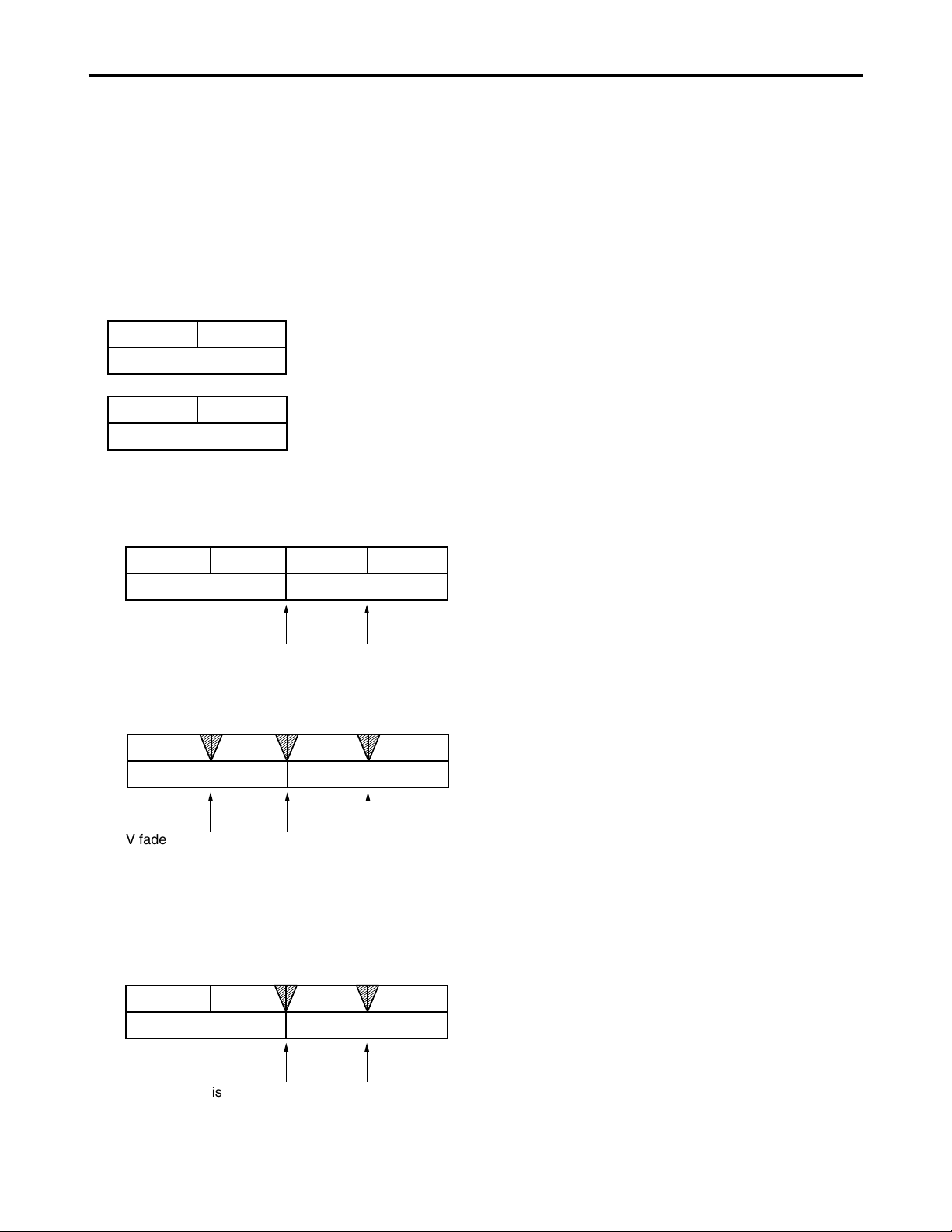
66
Audio V fade function
When the settings below are selected for audio processing
between clips or events (setup menu No.727: PB FADE) at
times such as during clip selection and playback or play list
playback, V fade or cut processing is performed for these
sections during playback.
The clips recorded over a multiple number of P2 cards and
the clips created by edit copying are shown in the figure
below.
Clips extending over more than one P2 card or
automatically divided and recorded clips using a P2 card
with a memory capacity of 8 GB or more
Event A Event B
Clip 2
Noise appears at the edit splice.
Clip 1-1 Clip 1-2
Clip 1
Clip 1-1
Clip 1
Clip 1-2
Event A Event B
Clip 2
V fade is performed instantaneously between all clips
and events to reduce noise.
Event A Event B
Clip 2
Clip 1-1 Clip 1-2
Clip 1
• When FADE is selected
V fade processing is performed for all the sections
between clips and between the events of edit-copoed
clips.
V fade is performed instantaneously to
eliminate the noise.
Event A Event B
Clip 2
Clip 1-1 Clip 1-2
Clip 1
Clip created by edit copying
• When CUT is selected
• When AUTO has been selected
V fade is automatically performed except between
events when clips extending over more than one P2
card or clips automatically divided and recorded using a
P2 card with a memory capacity of 8 GB or more have
been registered on a play list.
Described below is an example where the above two types
of clips are to be played back using the play list function.
Note:
This setting takes effect only when the power is on.
Page 67

67
Monitor output channel
The monitor output channels are selected using the
MONITOR SELECT and MONITOR MIX button as shown
below.
Audio recording channel and monitor output selection
Audio recording channel
The audio is selected as shown below by using the
AUDIO MIX switch, REC CH1/CH3 and REC CH2/CH4
buttons on the front panel.
Recording
track
CH1
CH2
CH3
CH4
Recording signal
CH1 input/CH2 input/CH1 input+CH2 input
CH1 input/CH2 input/CH1 input+CH2 input
CH3 input/CH4 input/CH3 input+CH4 input
CH3 input/CH4 input/CH3 input+CH4 input
Monitor
output
L
R
Output signal
CH1/CH2/CH3/CH4/CH1+CH2/CH3+CH4/
CH1+CH3/CH2+CH4
CH1/CH2/CH3/CH4/CH1+CH2/CH3+CH4/
CH1+CH3/CH2+CH4
Printed circuit board
F1 board (AUDIO)
The underlined items indicates the initial setting.
Switch No. Function
SW100 AUDIO INPUT IMPEDANCE SW
This sets the CH1 audio input
impedance.
HIGH
/600Ω
SW101 AUDIO INPUT IMPEDANCE SW
This sets the CH2 audio input
impedance.
HIGH
/600Ω
SW200 AUDIO INPUT IMPEDANCE SW
This sets the CH3 audio input
impedance.
HIGH
/600Ω
SW201 AUDIO INPUT IMPEDANCE SW
This sets the CH4 audio input
impedance.
HIGH
/600Ω
SW201
SW200
SW101
SW100
Page 68

68
Rack mounting
The memory card recorder can be mounted into a 19-inch
standard rack using the optional rack-mounting adaptors
(AJ-MA75P).
For the installation rails, it is recommended that the 18-inch
rail and bracket (model number CC3061-99-0400) by
Chassis Trak be used. (The complete slide rail and bracket
deck is not available from Panasonic.)
For further details, consult your dealer.
(1) Attach the inner members of the slide rails
Refer to the figure below for the locations where the
screws are to be attached.
ABCDEFGH
Notes:
•The length of the screws used is subject to
restriction. (B, H: 10 mm, F: 6 mm)
•Attach the inner members at the same symmetrical
positions on the left (L) side.
•Fix the members in place using 3 screws on each
side (total: 6 screws).
•The letters “A” to “H” are not actually marked on
the side panels.
(2) Attach the outer member brackets to the rack
Check that the height is the same for the left and right
brackets.
(3) Remove the four screws at the front for
attaching the left and right side panels
(4) Attach the AJ-MA75P rack mount adapter
using the removed 4 screws
(5) Remove the 4 rubber legs from the bottom of
the memory card recorder, and install the
memory card recorder in the rack
After the memory card recorder has been installed,
check that it moves smoothly along the rails.
Notes:
•Keep the temperature inside the rack from 41°F to
104°F (5°C to 40°C).
•Bolt the rack securely to the floor so that it will not
topple over when the memory card recorder is
drawn out.
Locations where the screws are secured on the right
(R) side of the inner members of the slide rails
Inner member
Rack-mounting adaptors
EIAJ Standard rack
Fasten it to the rack
with set screws.
Page 69

69
Condensation
Condensation occurs due to the same principle involved
when droplets of water form on a window pane of a heated
room. It occurs when the deck or card is moved between
places where the temperature or humidity varies greatly or
when, for instance:
• It is moved to a very humid place full of steam or a room
immediately after it has been heated up.
• It is suddenly moved from a cold location to a hot or humid
location.
When moving the deck to locations such as these, leave it
standing for about 10 minutes rather than switching on the
power immediately.
Maintenance
Before starting any maintenance work, switch the power to
OFF and, holding the plug, unplug the cord from the socket.
Use a soft cloth to clean the outside of the deck.
For stubborn dirt or stains, wipe the deck with a cloth that
has been lightly dampened with well-diluted kitchen
detergent and wrung out thoroughly.
After wiping off the dirt with the damp cloth, finish it off with
a dry cloth.
Note:
Do not use alcohol, benzene, thinners or any other
solvents as they may affect the color of external parts or
damage the deck’s coating.
Page 70

70
Error messages
When a warning occurs in this unit, the error number is
indicated on the counter display.
Open the DIAG menu to display a description of the error on
the counter display or monitor TV. When an operational
malfunction has occurred in the unit, the error number flashes
on the counter display.
DIAG menu
This displays the deck information.
Deck information includes “WARNING” information,
“HOURS METER” (usage time) information and “UMID
(Unique Material Identifier)” information.
A DIAG menu appears on the monitor when the monitor
is connected to the VIDEO OUT 3/SDI OUT 3 connector
(optional) on the rear panel.
Displaying the DIAG menu
(1) Press the DIAG button.
The DIAG menu screen is displayed on the monitor, and
the message is displayed on the counter display.
(2) Press the SEARCH button.
Each time the button is pressed, the display changes as
follows: “WARNING”, “HOURS METER”, “UMID INFO”
and so on.
Press the DIAG button again to return to the original
display.
Superimposed display
Warning information display
Normal screen
Front
display
Press DIAG button
Press SEARCH button
Hours meter information displayUMID information display
T R 00:00:00.00
EJECT
DIAG-MENU
NO WARNING
WARNING 0/0
DIAG-MENU
MATNO
COPY
OWNR
POS
DATE
TIME
UMID INFO
00001234005678BA
0080458201000001
0
JPN :ORG :USER
+3775m 3D
E 180’ 00’ 00.0”
N 90’ 00’ 00.0”
JAN-28-02
23:30:30 +03h00m
DIAG-MENU
Ser
G4TRA0001
H00
OPERATION
H20
LCD ON
H30
POWER ON
HOURS METER
0H
0H
0T
Page 71
71
Error messages (continued)
“WARNING” information display
• A warning message is displayed whenever a warning occurs.
When warnings have not been detected, “NO WARNING” is displayed.
• When multiple warning occur, the descriptions for each warning can be checked by turning the search dial.
If “T&S&M” is selected in the setup menu No. 008 (DISPLAY SEL), a message appears in the mode display whenever a
warning or error occurs.
When multiple events occur, the event with the highest priority is displayed.
Monitor display DescriptionPriority
high
low
Counter
display
Deck
operation
BUSY
Displayed while the clip information is being read or when the clip
configuration has changed.
No operations can be performed while this display is on the screen.
[Meaning]
• A card has been inserted or removed.
• Updating is now underway.
• Processing is now underway after recording.
• Other
BUSY
operation
continues
CANNOT REC
Displayed when data cannot be recorded on the P2 card.
[Meaning]
• An attempt has been made to record data when the card is writeprotected.
• An attempt has been made to record data when the card has no
more free memory space on it.
• An attempt has been made to record on a card that cannot be
used.
• The card status has changed during recording.
CANT
REC
stop
CANNOT PLAY
Displayed when play has been stopped by clip trouble or other
factors.
[Meaning]
• An attempt has been made to play clips when there are no clips
present.
• An attempt has been made to initiate play for a card that cannot be
used.
• Play is not acknowledged or it has been stopped for some other
reason.
CANT
PLAY
stop
INT SG
Displayed for the first two seconds when the REC button is pressed
and the E-E mode is established while SG, SG1 or SG2 has been
selected using the INPUT SELECT VIDEO button or while SG has
been selected using the INPUT SELECT AUDIO button.
INT SG
operation
continues
NO INPUT
Displayed for the first two seconds when the REC button is pressed
and the E-E mode is established while no input signals except for
analog audio signals are being supplied to the connector selected
using the INPUT SELECT button.
NO
INPUT
operation
continues
MARK ON /
MARK OFF
Displayed for two seconds when a shot mark has been added or
deleted.
MARK ON/
MARK OFF
operation
continues
Warning messages
Page 72

72
TURN POWER OFF
Displayed when trouble has occurred in reading data from the card or
writing data onto the card. To continue operation, turn the power off and
then back on.
E-30 stop
Error messages (continued)
Message
Error
Description
No.
Deck
operation
COMM ERROR
Displayed when the orders issued by the system control command have
not been followed even after 3 seconds have elapsed. To continue
operation, turn the power off and then back on.
E-37 stop
SYSTEM ERROR
Displayed when trouble has occurred in communication. To continue
operation, turn the power off and then back on.
E-38 stop
Error messages
Monitor display
No. Message
DescriptionPriority
high
low
Deck operation
If “E- ” lights up in the monitor display, the contents are displayed when the DIAG-MENU is opened.
E-21 REC WARNING
Displayed when trouble has occurred in the video or audio during
recording. To continue operation, turn the power off and then back
on.
stop
E-26 CARD ERR xx
Displayed when a data error caused by a P2 card has occurred during
recording. It remains displayed even after recording has stopped until the
next operation is performed. No display appears when an error has
occurred during playback. (“xx” denotes the slot number where the error
occurred.) Replace the P2 card in the slot where the error occurred.
stop
E-25 IRREGULAR CLIP
Displayed when there is an irregular clip. Recording can be continued
even while this message is displayed, but the clip should be fixed if,
for example, it is necessary to regenerate the time code.
After fixing the clip, turn the power off and then back on before
proceeding with the next operation.
operation
continues
E-50 BATTERY EMPTY
Displayed when a drop in the voltage of the internal clock's backup
battery has been detected while the power is on.
Replace the internal battery.
operation
continues
E-61 DVD DRIVE ERROR
Displayed when trouble has occurred in the DVD drive unit connection or
control. When a DVD drive unit is not connected, set the DVD setting to
[DISABLE]. When a DVD drive unit is connected, refer to the operating
instructions of the DVD drive unit.
stop
E-10 FAN STOP
Displayed when the fan motor has stopped.
Check the fan motor for foreign matter or objects.
operation
continues
Note:
•“E-50” appears when the backup battery has no more charge. After consulting with your dealer, replace it with a new
battery (CR2032 or its equivalent). After replacing the battery, be absolutely sure to set the deck’s internal clock using
setup menu No. 069 (CLOCK SET).
Page 73

73
“HOURS METER” information display
Turn the search dial to move the cursor ( ). The description for the item where the cursor is located is shown on the
counter display.
Item DescriptionNo.
Counter display
Displays the deck’s serial No.Ser
OPERATION
Displays the time that the power has been supplied in one-hour
units.
H00 0H - 99999H
LCD ON
Displays the time during which the LCD monitor has been
lighted in 1-hour increments.
H20 0H - 99999H
POWER ON
The number of times the power has been turned on is displayed
in single units.
H30 0T - 99999T
Notes:
•The resettable items in the “HOURS METER” information are reset by the shop when performing maintenance or other
work.
•The search buttons and the search dial cannot be operated while the DIAG menu is displayed.
Error messages (continued)
LAN NO LINK
Displayed when there is a problem in the LAN connections.
Check the LAN connections.
To continue operation, turn the power off and then back on.
E-41
Message DescriptionNo.
DHCP TIMEOUT
Displayed when there is a problem in the connections with the DHCP server.
Check the DHCP server settings.
To continue operation, turn the power off and then back on.
E-43
LAN ERROR
Displayed when the LAN connection or disconnection has failed.
To continue operation, turn the power off and then back on.
Check the LAN settings and connections if E-49 appears again.
E-49
Error information in LAN mode
Page 74

74
The underlining indicates the factory settings.
Any changes to the settings can be made using the
setup menu items listed below.
RS-232C interface
The memory card recorder can be operated by commands
when the RS-232C interface is used.
(See command table on pages 75, 76)
Conditions for acknowledging commands
from RS-232C interface
• The front panel REMOTE button is lit
•The setup menu No. 204 (RS232C SEL) must be ON.
If the above conditions are not met, [ACK] + [STX] ER001
[EXT] is returned to the external deck.
Whether the [ACK] code is returned depends on the
setting which has been selected for setup menu item No.
209 (RETURN ACK).
Hardware specifications
External interface specifications
• Connector specifications
Connector:
D-SUB 25-pin (crossover cable supported)
Pin No.
1
2
3
4
5
6
7
20
Signal
FG
RXD
TXD
CTS
RTS
DTR
SG
DSR
Description
Protective ground
(Frame ground)
Received data
(Data is sent to PC.)
Transmitted data
(Data is received from PC.)
Clear to send
(Shorted with pin 5.)
Request to send
(Shorted with pin 4.)
Data terminal ready
(No processing)
Signal ground
(Signal ground)
Data set ready
(+ voltage output after communication
enable status)
• Example of connection with controller (PC)
(Using crossover cable with D-SUB 25-pin connectors)
1
2
3
4
5
6
7
20
FG
TXD
RXD
RTS
CTS
DSR
SG
DTR
1
2
3
4
5
6
7
20
FG
RXD
TXD
CTS
RTS
DTR
SG
DSR
deck side
PC side
(D-SUB 25-pin connector)
(Using crossover cable with D-SUB 9-pin and 25-pin
connectors)
2
3
4
5
6
7
8
RXD
TXD
DTR
SG
DSR
RTS
CTS
1
2
3
4
5
6
7
20
FG
RXD
TXD
CTS
RTS
DTR
SG
DSR
deck side
PC side
(D-SUB 9-pin connector)
Software specifications (Protocol)
Communication parameters
Communication
system
Communication
speed
Bit length
Stop bit
Parity bit
ACK code
Asynchronous, full duplex
300/600/1200/2400/4800/9600
7bit/8 bit
1 bit/2 bit
NONE
/ODD/EVEN
ACK code returned
/ACK code not
returned
Note:
The ACK code is what is returned from
the memory card recorder to the
controller when data has been
successfully sent from the controller.
Send format
[controller (PC)
→ memory card recorder]
Data format
20H<XX<7FH
(XX = ASCII code: symbols, numbers upper-case
letters)
[command] :
Command identifier; a 3-byte identifier (ASCII code:
symbols, numbers, upper-case letters) is sent as the
command.
[:] :
This code serves as a delimiter between the
command and data.
[data] :
Data (ASCII code: symbols, numbers, uppercase
letters) can be added in the number of bytes
required.
Outline of send procedure from controller
• The send command starts with STX (start of text = 02h).
The command is then identified by COMMAND which
follows and the data is added as required.
The format ends with ETX (end of text = 03h).
•When a different command is to be sent, a response is
awaited from the memory card recorder, and then the
command is sent.
•If STX is sent again before ETX is sent, the receive data
buffer inside the memory card recorder is cleared. A
command error is returned to the controller, and the
data is newly processed with STX which was received
again at the head.
[STX] [command] [:] [data] [ETX]
02h XX XX XX 3Ah XX.....XX 03h
Communication
parameter
Communication
speed
Bit length
Stop bit
Parity bit
ACK code
Setup menu item
No.205 BAUD RATE
No.206 DATA LENGTH
No.207 STOP BIT
No.208 PARITY
No.209 RETURN ACK
Page 75

75
SHTL
FORWARD
[STX] OSF:data [ETX]
↔ [STX] OSF [ETX]
This is the forward direction shuttle
command.
data = n : speed data
0 : STILL
1 :
×
0.03
2 :
×
0.1
3 :
×
0.2
4 :
×
0.5
5 :
×
1
6 :
×
2
7 :
×
4
8 :
×
8
9 :
×
16
A :
×
32
Note:
The x16 and x32 speed differ according to
the setting selected for setup menu No. 101
(SHTL MAX).
SHTL
REVERSE
[STX] OSR:data [ETX]
↔ [STX] OSR [ETX]
This is the reverse direction shuttle
command.
data = n : speed data
0 : STILL
1 :
×
0.03
2 : ×0.1
3 :
×
0.2
4 : ×0.5
5 :
×
1
6 : ×2
7 :
×
4
8 : ×8
9 :
×
16
A :
×
32
Note:
The x16 and x32 speed differ according to
the setting selected for setup menu No. 101
(SHTL MAX).
RS-232C interface (continued)
Return format
[memory card recorder
→ controller (PC)]
The following responses are made to the command. If
necessary, more than one response is made.
When the communication has terminated normally
The receive completion message is returned.
The execution completion message is returned.
[command] :
This is the message (data) which is returned or the
execution completion message identifier.
[data] :
This is the data to be returned. It can be omitted.
Example :
Send command
Return message (data)
[STX] OPL [ETX] → [ACK] [STX] OPL [ETX]
When the communication has terminated abnormally
When processing is not possible due to incorrect data or
trouble in the memory card recorder
The receive completion message is returned.
An error code is returned.
Error code table
ER001 : Invalid command
• Unsupported command received.
• Error in command execution
ER002 : Parameter error
ER1FF : Deck system error
[STX] [ERN
1 N2 N3] [ETX]
02h Error code 03h
[ACK]
06h
[NACK]
15h
[STX] [command] [data] [ETX]
02h XX XX XX XX.....XX 03h
[ACK]
06h
Deck
operation
Send command
Return (completion)
message
REWIND
[STX] ORW [ETX]
↔ [STX] ORW [ETX]
This command is for rewinding.
The resulting output picture and sound statuses
differ according to the settings selected for the
setup menu No. 105 (AUTO EE SEL).
The maximum speed differs according to the
setting selected for setup menu No. 102 (FF.
REW MAX). For details, see each setup menu.
FAST
FORWARD
[STX] OFF [ETX]
↔ [STX] OFF [ETX]
This command is for fast forwarding.
The resulting output picture and sound statuses
differ according to the settings selected for the
setup menu No. 105 (AUTO EE SEL).
The maximum speed differs according to the
setting selected for setup menu No. 102 (FF.
REW MAX). For details, see each setup
menu.
REC
[STX] ORC [ETX]
↔ [STX] ORC [ETX]
This command is for starting the recording.
Deck
operation
Send command
Return (completion)
message
STOP
[STX] OSP [ETX]
↔ [STX] OSP [ETX]
This command is for stopping the travel.
PLAY
[STX] OPL [ETX]
↔ [STX] OPL [ETX]
This command is for starting playback.
Command table
Commands relating to operation control
Notes:
•As for the return (completion) message, [ACK] is
first returned when data is received, and the
execution message is subsequently returned. It is
only the execution message which is listed in this
table.
•In the case of commands not listed in the table,
ER001 (invalid command) is returned after [ACK]
has been returned.
Page 76
76
RS-232C interface (continued)
Commands relating to inquiries
Notes:
•As for the return (completion) message, [ACK] is
first returned when data is received, and the
execution message is subsequently returned. It is
only the execution message which is listed in this
table.
•In the case of commands not listed in the table,
ER001 (invalid command) is returned after [ACK]
has been returned.
CTL/TC
DATA
REQUEST
[STX] QCD [ETX]
↔ [STX] CD data [ETX]
This command is for inquiring about the
counter value.
data = f w gh mm ss ff
f =F
w =S
gh =
CTL mode:
g = SP (20h) : for a plus display
– (2Dh) : for a minus display
h =0 – 9 : hours
TC mode:
gh = 00 – 23 : hours
mm = 00 – 59 : minutes
ss = 00 – 59 : seconds
[525i system]
ff = 00 – 29 : frames
[625i system]
ff = 00 – 24 : frames
Note:
CTL or TC is returned, whichever
corresponds to the front display mode.
STATUS
REQUEST
[STX] QOP [ETX]
↔
[STX] [ETX]
This command is for inquiring about the
memory card recorder’s operation mode.
=
OFF : FAST FORWARD
OPL : PLAY
ORC : REC
ORW : REWIND
OSP : STOP
SRS : (IN/OUT) PREROLL
OSF : SHTL FORWARD
OSR : SHTL REVERSE
OJG : JOG FORWARD/REVERSE
OSW : VAR FORWARD/REVERSE
ID
(deck No.)
REQUEST
[STX] QID [ETX]
↔ [STX] data [ETX]
This command is for inquiring about the
memory card recorder used.
data = AJ-SPD850
Deck
operation
Send command
Return (completion)
message
Page 77

77
Connector signals
VIDEO IN
SDI IN
(DIGITAL)
Y, PB, PR
(ANALOG)
VIDEO IN
REF VIDEO
IN
BNC
×
2, Active through
(Board, option)
BNC
×
3
(Board, option)
BNC
×
2, Loop-through,
75 Ω termination switch provided
BNC
×
2, Loop-through,
75 Ω termination switch provided
RS-422A REMOTE (9P)
(REMOTE)
Pin No.
1
2
3
4
5
6
7
8
9
Signal
FRAME GROUND
TRANSMIT A
RECEIVE B
RECEIVE COMMON
—
TRANSMIT COMMON
TRANSMIT B
RECEIVE A
FRAME GROUND
RS-232C
D-SUB 25-pin (crossover cable supported)
Pin No.
1
2
3
4
5
6
7
20
Signal
FG
RXD
TXD
CTS
RTS
DTR
SG
DSR
Description
Protective ground
(Frame ground)
Received data
(Data is sent to PC.)
Transmitted data
(Data is received from PC.)
Clear to send
(Shorted with pin 5.)
Request to send
(Shorted with pin 4.)
Data terminal ready
(No processing)
Signal ground
(Signal ground)
Data set ready (+ voltage output after
communication enable status)
ENCODER (15P)
Pin No.
1
2
3
4
5
6
7
8
9
10
11
12
13
14
15
Signal
—
BLACK LEVEL
C LEVEL
GND
+ 9V
SYSTEM H 0
SYS. SC COARSE (2)
– 9V
CHROMA PHASE
VIDEO LEVEL
RET GND
—
—
SYS. SC FINE
SYS. SC COARSE (1)
VIDEO OUT
SDI OUT
(DIGITAL)
Y, PB, PR
(ANALOG)
VIDEO OUT
BNC
× 3
BNC
× 3
BNC
×
3
AUDIO IN
SDI IN
(DIGITAL)
AUDIO IN
(DIGITAL)
AUDIO IN
(ANALOG)
TIME CODE
IN
BNC
× 2, Active through
BNC × 2 (CH1/CH2, CH3/CH4)
AES/EBU format
XLR
× 4 (CH1, CH2, CH3, CH4)
XLR
× 1
AUDIO OUT
SDI OUT
(DIGITAL)
AUDIO OUT
(DIGITAL)
AUDIO OUT
(ANALOG)
TIME CODE
OUT
MONITOR
OUT
HEADPHONES
(front)
BNC
× 3
BNC × 2 (CH1/CH2, CH3/CH4)
AES/EBU format
XLR
× 4 (CH1, CH2, CH3, CH4)
XLR
× 1
XLR
× 2 (L/R)
Stereo mini jack
Page 78

78
Specifications
Power supply: AC 100 – 240 V, 50 / 60 Hz
Power consumption:
80 W, 105 W (with all options)
Operating ambient temperature:
5 °C to 40 °C
Operating ambient humidity:
10 % to 80 % (no condensation)
Mass:
15 kg (30.8 lb)
Dimensions (W x H x D):
424 mm x 175.2 mm x 430 mm
(16 3/4 inches x 6 15/16 inches x 16 15/16 inches)
(Not including the support legs, connectors, and
SEARCH dial)
Recording format:
DVCPRO50/DVCPRO/DV format selectable
Recording video signal:
525i/625i system selectable
Recording audio signal:
DVCPRO50 : 48 kHz 16-bit 4 channels
DVCPRO/DV : 48 kHz 16-bit 2/4 channels selectable
Recording times:
Note:
All of the above times apply when single clips are
recorded continuously one after the other on the P2
card.
Depending on the number of the clips to be
recorded, the recordable time may be shorter than
the times given above.
Digital slow:
–1.0x to +1.0x speed
VIDEO
Digital video
Sampling frequencies:
Y: 13.5 MHz, P
B/PR: 6.75 MHz (DVCPRO50)
Quantizing:
8 bits
Video compression method:
DV-Based compression (SMPTE 314M)
Video compression rate:
DVCPRO50: 1/3.3
DVCPRO : 1/5
Error correction:
Reed-Solomon product code
Bit rate:
DVCPRO50: 50 Mbps
DVCPRO : 25 Mbps
Component IN/component OUT
Video bandwidth:
For AJ-SPD850P
Y : 30 Hz to 5.75 MHz (-2.0 dB)
P
B/PR
: 30 Hz to 2.75 MHz (-2.0 dB)
For AJ-SPD850E
Y : 25 Hz to 5.75 MHz (-2.0 dB)
P
B/PR : 25 Hz to 2.75 MHz (-2.0 dB)
S/N ratio: Better than 55 dB
K factor: Less than 1 % (Y 2T)
Y/C delay: Less than 20 nsec
Composite IN/composite OUT
Video bandwidth:
For AJ-SPD850P
Y : 30 Hz to 5.5 MHz (-3.0 dB)
For AJ-SPD850E
Y : 25 Hz to 5.5 MHz (-3.0 dB)
Y/C delay: Less than 20 nsec
Video input connector
Analog component input:
BNC x 3 (Y, PB, PR)
Y : 1.0 V [p-p], 75 Ω
For AJ-SPD850P
P
B/PR : 0.486 V/0.7 V [p-p] selectable
75 Ω (75 % color bar, setup level 7.5 %)
For AJ-SPD850E
P
B/PR : 0.7 V [p-p]
75 Ω (100 % color bar)
Analog composite input:
BNC x 2, loop-through, 75 Ω on/off
VIDEO: 1.0 V [p-p] (75 Ω)
Reference input:
Analog composite, BNC x 2, loop-through,
75 Ω on/off
SDI input (option):
BNC x 2, active through,
complies with SMPTE259M-C
/ITU-R BT.656-4 standard
Video Output Connector
Analog component output:
BNC x 3 (Y, PB, PR)
Y : 1.0 V [p-p], 75 Ω
For AJ-SPD850P
P
B/PR : 0.486 V/0.7 V [p-p] selectable
75 Ω (75 % color bar, setup level 7.5 %)
For AJ-SPD850E
P
B/PR: 0.7 V [p-p]
75 Ω (100 % color bar)
Analog composite output:
BNC x 3, video 1, video 2,
video 3 (superimpose on/off)
SDI output (option):
BNC x 3, complies with SMPTE259M-C
/ITU-R BT.656-4 standard
SDI 1, SDI 2, SDI 3 (superimpose on/off)
Video Signal Adjustment
Video output gain:
±3 dB
Video output chroma gain:
±3 dB
Video output HUE (chroma phase):
±30 °
Video output setup level (black level):
±14 IRE (±100 mV)
Video output sync phase:
±15 µsec
Video output SC phase:
±180 °
indicates safety information.
GENERAL
Card
model
AJP2C002SG
AJP2C004HG
AJP2C008HG
Number
of
Cards
1
5
1
5
1
5
DVCPRO
(2-channel audio)
approx. 8 minutes
approx.40 minutes
approx.16 minutes
approx.80 minutes
approx.32 minutes
approx.160 minutes
DVCPRO50
(4-channel audio)
approx. 4 minutes
approx.20 minutes
approx. 8 minutes
approx.40 minutes
approx.16 minutes
approx.80 minutes
Recording format
Page 79

79
Specifications (continued)
AUDIO
Digital Audio
Sampling frequencies:
48 kHz (synchronous with video)
Quantizing:
16 bits
Frequency response:
20 Hz to 20 kHz ±1.0 dB (at the reference level)
Dynamic range:
Better than 90 dB
(1 kHz, emphasis OFF, “A” weighted)
Distortion:
Less than 0.05%
(1 kHz, emphasis OFF, reference level)
Crosstalk:
Less than –80 dB (1 kHz, between 2 channels)
Headroom:
For AJ-SPD850P: 20 dB
For AJ-SPD850E: 18 dB
De-emphasis:
T1 = 50 µsec, T2 = 15 µsec (auto on/off)
Audio Input Connector
Analog input (CH1, CH2, CH3, CH4):
XLR x 4, 600 Ω/high impedance selectable (factory
setting: HIGH), +4/0/–20 dBu selectable
Digital input (CH1/CH2, CH3/CH4):
BNC x 2, AES/EBU format
SDI input (option):
BNC x 2, active through,
complies with SMPTE259M-C/272M-A
/ITU-R BT.656-4 standard
Audio Output Connector
Analog output (CH1, CH2, CH3, CH4):
XLR x 4, low impedance, +4/0/–20 dBu selectable
Digital output (CH1/CH2, CH3/CH4):
BNC x 2, AES/EBU format, 75 Ω, 1.0 ± 0.2 V [p-p]
SDI output (option):
BNC x 3, 75 Ω,
complies with SMPTE259M-C/272M-A
/ITU-R BT.656-4 standard
Monitor output:
XLR x 2, low impedance, +4/0/–20 dBu selectable
Headphones:
Stereo mini jack, 8 Ω, variable level
Other Input/Output Connectors
Time code input:
XLR x 1, 0.5 V to 8 V [p-p], 10 kΩ
Time code output:
XLR x 1, low impedance, 2.0 V ± 0.5 V [p-p]
RS-422A input/output:
D-sub 9-pin, RS-422A interface
RS-232C:
D-sub 25-pin, RS-232C interface
Encoder remote:
D-sub 15-pin
Weight and dimensions when shown are approximately.
Specifications are subject to change without notice.
Page 80

Information on Disposal for Users of Waste Electrical & Electronic Equipment (private households)
This symbol on the products and/or accompanying documents means that used electrical and electronic products
should not be mixed with general household waste.
For proper treatment, recovery and recycling, please take these products to designated collection points, where they
will be accepted on a free of charge basis. Alternatively, in some countries you may be able to return your products
to your local retailer upon the purchase of an equivalent new product.
Disposing of this product correctly will help to save valuable resources and prevent any potential negative effects on
human health and the environment which could otherwise arise from inappropriate waste handling. Please contact
your local authority for further details of your nearest designated collection point.
Penalties may be applicable for incorrect disposal of this waste, in accordance with national legislation.
For business users in the European Union
If you wish to discard electrical and electronic equipment, please contact your dealer or supplier for further information.
Information on Disposal in other Countries outside the European Union
This symbol is only valid in the European Union.
If you wish to discard this product, please contact your local authorities or dealer and ask for the correct method of disposal.
PANASONIC BROADCAST & TELEVISION SYSTEMS COMPANY
UNIT COMPANY OF PANASONIC CORPORATION OF NORTH AMERICA
Executive Office:
One Panasonic Way 4E-7, Secaucus, NJ 07094 (201) 348-7000
EASTERN ZONE:
One Panasonic Way 4E-7, Secaucus, NJ 07094 (201) 348-7621
Southeast Region:
1225 Northbrook Parkway, Ste 1-160, Suwanee, GA 30024 (770) 338-6835
Central Region:
1707 N Randall Road E1-C-1, Elgin, IL 60123 (847) 468-5200
WESTERN ZONE:
3330 Cahuenga Blvd W., Los Angeles, CA 90068 (323) 436-3500
Government Marketing Department:
52 West Gude Drive, Rockville, MD 20850 (301) 738-3840
Broadcast PARTS INFORMATION & ORDERING:
9:00 a.m. – 5:00 p.m. (EST) (800) 334-4881/24 Hr. Fax (800) 334-4880
Emergency after hour parts orders (800) 334-4881
TECHNICAL SUPPORT:
Emergency 24 Hour Service (800) 222-0741
Panasonic Canada Inc.
5770 Ambler Drive, Mississauga, Ontario L4W 2T3 (905) 624-5010
Panasonic de Mexico S.A. de C.V.
Av angel Urraza Num. 1209 Col. de Valle 03100 Mexico, D.F. (52) 1 951 2127
Panasonic Puerto Rico Inc.
San Gabriel Industrial Park, 65th Infantry Ave., Km. 9.5, Carolina, Puerto Rico 00630 (787) 750-4300
EP
Panasonic Broadcast Europe
Panasonic Marketing Europe GmbH
Hagenauer Str. 43, 65203 Wiesbaden-Biebrich Deutschland Tel: 49-611-235-481
© 2004 Matsushita Electric Industrial Co., Ltd. All Rights Reserved.
 Loading...