

Panasonic aj-hvf20 Operation Manual

ENGLISH
FRANÇAIS
2˝ Electronic HD View Finder
AJ-
Operating Instructions

E– 1
Caution:
O
The interior of this product contains high-voltage components. Do not
disassemble the product.
O
Be careful not to point the eyepiece directly at the sun.
WARNING:
TO REDUCE THE RISK OF FIRE OR SHOCK HAZARD, DO NOT
EXPOSE THIS EQUIPMENT TO RAIN OR MOISTURE.
FCC Note:
This device complies with Part 15 of the FCC Rules. To assure continued
compliance follow the attached installation instructions and do not make any
unauthorized modifications.
This equipment has been tested and found to comply with the limits for a class A
digital device, pursuant to Part 15 of the FCC Rules. These limits are designed to
provide reasonable protection against harmful interference when the equipment is
operated in a commercial environment. This equipment generates, uses, and can
radiate radio frequency energy and, if not installed and used in accordance with the
instruction manual, may cause harmful interference to radio communications.
Operation of this equipment in a residential area is likely to cause harmful
interference in which case the user will be required to correct the interference at his
own expense.
Operating precaution
Operation near any appliance which generates strong magnetic fields may
give rise to noise in the video and audio signals. If this should be the case,
deal with the situation by, for instance, moving the source of the magnetic
fields away from the unit before operation.
indicates safety information.

E– 2
ENGLISH
Contents
Features . . . . . . . . . . . . . . . . . . . . . . . . . . . . . . . . . . . . . . . . . . . . . . . . . . . . . . . . . . .
E– 3
Specifications . . . . . . . . . . . . . . . . . . . . . . . . . . . . . . . . . . . . . . . . . . . . . . . . . . . . . .
E– 3
Parts and Their Functions . . . . . . . . . . . . . . . . . . . . . . . . . . . . . . . . . . . . . . . . . . . .
E– 4
Adjusting the Viewfinder . . . . . . . . . . . . . . . . . . . . . . . . . . . . . . . . . . . . . . . . . . . . .
E– 7
Adjusting the Mounting Height of the Viewfinder . . . . . . . . . . . . . . . . . . . . . . . . . .
E– 7
Mounting the Viewfinder . . . . . . . . . . . . . . . . . . . . . . . . . . . . . . . . . . . . . . . . . . . . .
E– 8
Detaching the Viewfinder . . . . . . . . . . . . . . . . . . . . . . . . . . . . . . . . . . . . . . . . . . . .
E– 8
Position Adjustment . . . . . . . . . . . . . . . . . . . . . . . . . . . . . . . . . . . . . . . . . . . . . . . .
E– 9
Diopter Adjustment . . . . . . . . . . . . . . . . . . . . . . . . . . . . . . . . . . . . . . . . . . . . . . . .
E– 10
Screen Adjustment . . . . . . . . . . . . . . . . . . . . . . . . . . . . . . . . . . . . . . . . . . . . . . . .
E– 10
Detaching the Eyepiece . . . . . . . . . . . . . . . . . . . . . . . . . . . . . . . . . . . . . . . . . . . .
E– 11
Mounting the Microphone . . . . . . . . . . . . . . . . . . . . . . . . . . . . . . . . . . . . . . . . . . . .
E– 12

E– 3
Features
O
The high-resolution CRT delivers superb picture sharpness, making focusing easier.
O
The low-flare CRT makes the screen clear and easy on the eyes.
O
The large eyepiece aperture makes it possible to see the screen even when holding the
viewfinder at some distance from your eye.
O
The eyepiece is easily detachable.
O
Easy, one-touch left-right and forward-backward position adjustment.
Power supply: DC 12 V (supplied by camera)
Power consumption: 3.3 W
Specifications
Picture tube:
2-inch high-resolution monochrome picture tube
Image system:
1080 lines, 59.94 Hz
External adjustment controls:
Controls (BRIGHT, CONTRAST, PEAKING)
Switches (TALLY HIGH/OFF/LOW, ZEBRA ON/OFF)
Allowable temperature range:
32°F to 104°F (0°C to 40°C)
Allowable humidity range:
85% or less (no condensation)
External dimensions (WaHaD):
9
1
/2˝a3 3/16˝a8 1/8˝ (240a80a206 mm)
Weight:
2.112 lb (960 g)
E– 4
ENGLISH
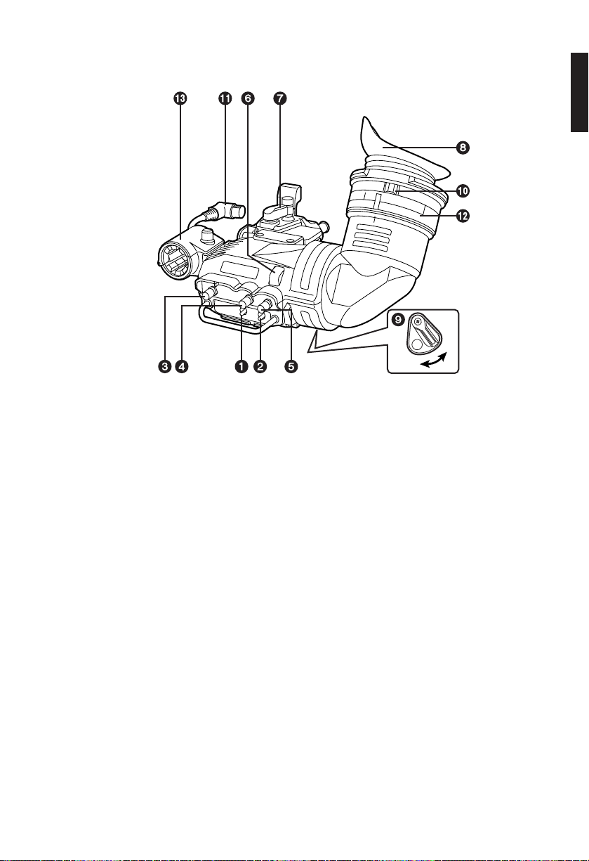
Parts and Their Functions
Displays a zebra pattern inside the viewfinder.
ON: Displays a zebra pattern.
OFF: No zebra pattern displayed.
The details of the display, such as the type of zebra pattern, will differ depending
on the camera used with the viewfinder. Refer to the instruction manual of the
camera for details.
ZEBRA (Zebra Pattern) Switch
1
Controls the front tally lamp.
HIGH: Makes the front tally lamp brighter.
OFF: Turns the front tally lamp off.
LOW: Makes the front tally lamp dimmer.
TALLY Switch
2
Adjusts the outlines of the images in the viewfinder to make focusing easier. The setting
of this control has no effect on the output signal of the camera.
PEAKING Knob
3
Adjusts the contrast of the screen inside the viewfinder. The setting of this control has
no effect on the output signal of the camera.
CONTRAST Knob
4
ON
OFF

E– 5
Lights when the VTR is recording and the TALLY switch is set to HIGH or LOW. Also,
flashes on and off as a warning indication, in the same manner as the REC lamp, inside
the viewfinder.
The brightness of the front tally lamp is controlled by the setting of the TALLY switch
(HIGH or LOW).
Front Tally Lamp
6
Loosen this lever to adjust the viewfinder position in the forward, backward, right or left
direction.
Viewfinder Forward-Backward/Left-Right Position Clamp Lever
7
Lights when the VCR is recording. Also, flashes on and off as a warning indication, in
the same manner as the REC lamp inside the viewfinder.
The back tally lamp is hidden when the lever is in the OFF position.
Back Tally Lamp
9
Adjust this control to match the vision of the person using the camera so that the image
on the screen in the viewfinder is as clear as possible.
Diopter Adjustment Ring
:
Connection Plug
;
Lock Ring
<
Microphone Holder
=
Eyepiece
8
Parts and Their Functions
Adjusts the brightness of the screen inside the viewfinder. The setting of this control has
no effect on the output signal of the camera.
BRIGHT (Brightness) Knob
5
E– 6
ENGLISH
Parts and Their Functions
The lamp and picture tube indications will differ depending on the camera used with the
viewfinder.
Refer to the instruction manual of the camera for details.
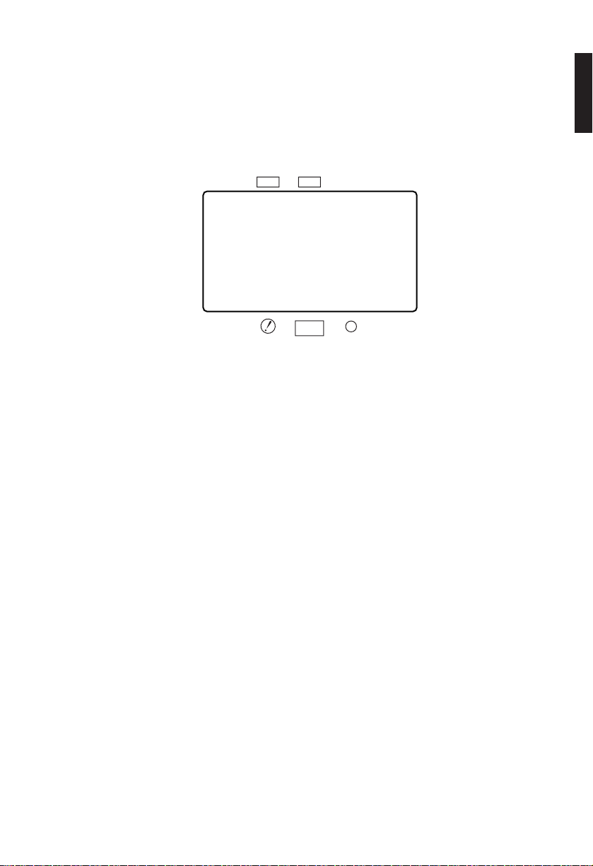
Internal LEDs
TALLY / REC
BATT
VTR
SAVE
E– 7
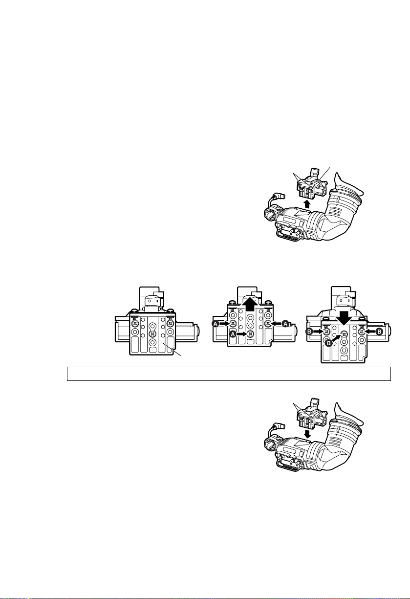
O
Adjusting the height of the mounting unit
Mounting unit
Screws
1.
Detach the two screws, the detach the
mounting unit.
Screws
3.
Secure the mounting unit in place with the two
screws.
2.
Replace the three screws in the positions indicated as Aor Bfrom the present
positions and change the position of the metal fitting.
Adjusting the Viewfinder
Adjusting the Mounting Height of the Viewfinder
Metal fitting
Re-fix the metal fitting by fastening the screws together with the spring washer.
The mounting height of the viewfinder can be adjusted using the method described
below.
Adjust the height of the mounting unit as required.
O
At the time of shipping, the mounting height is set for use with the AJ-HDC10A and
AJ-HDC20A models.
 Loading...