

Page 1
Operating Instructions
Hard Disk Storage Unit
Model No.
AJ-HRW10G
Before operating this product, please read the instructions carefully and save this manual for
future use.
S0409H0 -M
Printed in Japan
D
ENGLISH
VQT2C68
Page 2

Read this first!
CAUTION
RISK OF ELECTRIC SHOCK
DO NOT OPEN
CAUTION: TO REDUCE THE RISK OF ELECTRIC SHOCK,
REFER TO SERVICING TO QUALIFIED SERVICE PERSONNEL.
WARNING:
TO REDUCE THE RISK OF FIRE OR SHOCK
HAZARD, DO NOT EXPOSE THIS
EQUIPMENT TO RAIN OR MOISTURE.
TO REDUCE THE RISK OF FIRE OR SHOCK
HAZARD, KEEP THIS EQUIPMENT AWAY
FROM ALL LIQUIDS. USE AND STORE ONLY
IN LOCATIONS WHICH ARE NOT EXPOSED
TO THE RISK OF DRIPPING OR SPLASHING
LIQUIDS, AND DO NOT PLACE ANY LIQUID
CONTAINERS ON TOP OF THE EQUIPMENT.
DO NOT REMOVE COVER (OR BACK).
NO USER SERVICEABLE PARTS INSIDE.
The lightning flash with arrowhead symbol,
within an equilateral triangle, is intended to
alert the user to the presence of uninsulated
“dangerous voltage” within the product’s
enclosure that may be of sufficient
magnitude to constitute a risk of electric
shock to persons.
The exclamation point within an equilateral
triangle is intended to alert the user to the
presence of important operating and
maintenance (service) instructions in the
literature accompanying the appliance.
Declaration of Conformity
Model Number:
Trade Name:
Responsible Party:
Support contact:
This device complies with Part 15 of the FCC Rules.
Operation is subject to the following two conditions:
(1) This device may not cause harmful interference, and (2)
this device must accept any interference received, including
interference that may cause undesired operation.
FCC Note:
This equipment has been tested and found to comply with the
limits for a class B digital device, pursuant to Part 15 of the
FCC Rules. These limits are designed to provide reasonable
protection against harmful interference in a residential
installation. This equipment generates, uses, and can radiate
radio frequency energy and, if not installed and used in
accordance with the instruction manual, may cause harmful
interference to radio communications. However, there is no
guarantee that interference will not occur in a particular
installation. If this equipment does cause harmful interference
to radio or television reception, which can be determined by
turning the equipment off and on, the user is encouraged to try
to correct the interference by one or more of the following
measures:
Reorient or relocate the receiving antenna.
Increase the separation between the equipment and
receiver.
Connect the equipment into an outlet on a circuit different
from that to which the receiver is connected.
Consult the dealer or an experienced radio/TV technician for
help.
The user may find the booklet “Something About
Interference” available from FCC local regional offices
helpful.
AJ-HRW10G
PANASONIC
Panasonic Corporation of North America
One Panasonic Way, Secaucus, NJ
07094
Panasonic Broadcast & Television
Systems Company 1-800-524-1448
WARNING:
Always keep memory cards or accessories (Ferrite
core, Binder, Screws) out of the reach of babies
and small children.
CAUTION:
In order to maintain adequate ventilation, do not
install or place this unit in a bookcase, built-in
cabinet or any other confined space. To prevent risk
of electric shock or fire hazard due to overheating,
ensure that curtains and any other materials do not
obstruct the ventilation.
CAUTION:
TO REDUCE THE RISK OF FIRE OR SHOCK
HAZARD AND ANNOYING INTERFERENCE,
USE THE RECOMMENDED ACCESSORIES
ONLY.
CAUTION:
Excessive sound pressure from earphones and
headphones can cause hearing loss.
indicates safety information.
Warn ing:
To assure continued FCC emission limit compliance, follow the
attached installation instructions and the user must use only
shielded interface cables when connecting to host computer or
peripheral devices. Also any unauthorized changes or
modifications to this equipment could void the user’s authority
to operate this device.
2
Page 3

Read this first! (continued)
A rechargeable battery that is recyclable powers the product you have purchased.
<For USA-California Only>
This product contains a CR Coin Cell Lithium Battery which contains Perchlorate Material — special handling may apply.
See www.dtsc.ca.gov/hazardouswaste/perchlorate.
EU
To remove the battery
Main Power Battery (Ni-Cd / Ni-MH / Li-ion Battery)
To detach the battery, please proceed in the reverse order of the installation method described in this manual.
(Refer to page 8 for the detail.)
If a battery made by any other manufacturer is to be used, check the Operating Instructions accompanying the battery.
Back-up Battery (Lithium Battery)
For the removal of the battery for disposal at the end of its service life, please consult your dealer.
3
Page 4

Contents
Read this first! .............................................2
Standard accessories .................................5
Precautions for Use.....................................5
Overview.......................................................5
Control reference guide ..............................6
Front Panel ............................................................. 6
Back Panel ............................................................. 7
Power Supply ...............................................8
Mounting the Battery .............................................. 8
Removing the battery ............................................. 8
How to install the 5-inch bay units ............9
For better performance ............................. 11
Shock resistance and vibration resistance ............11
Handling HDDs ......................................................11
Moving the unit ......................................................11
Recorded data ...................................................... 12
Cleaning ............................................................... 12
Handling the touch panel ...................................... 12
Precautions when connecting the LAN cable ....... 13
Use of external DC power supply ......................... 13
Battery pack ......................................................... 13
Basic operations........................................14
Inserting P2 card .................................................. 14
Ejecting P2 card ................................................... 14
To Prevent Accidental Erasure of P2 Card Content
Turning the unit ON and OFF / Exiting ................. 15
Functions .............................................................. 16
Power indication ................................................... 16
..... 14
Checking the clips in P2 card/HDD ..........25
Copying individual clips (COPY) .......................... 27
Deleting individual clips (DELETE) ....................... 27
Viewing clip properties (PROP) ............................ 28
Select listed devices (device selection buttons) ... 29
Selecting clips to display (FILTER) ....................... 30
Changing how clips are listed (SORT) ................. 31
Viewing slot numbers and HDD status ................. 31
Playing the clips ........................................32
Setting the FF/REW rate ...................................... 33
Sharing the folders ....................................34
Returning the clips in the RECYCLE folder
...35
Formatting ..................................................36
Checking the state of all slots ..................37
System setting ...........................................38
Configuring network settings (Network) ............... 38
Specifying the display language (Language) ....... 38
Specifying copy options (Copy Setting) ................ 39
Changing thumbnail display (Thumbnail) ............. 39
Checking SMART Info .......................................... 40
Setting battery level warnings (Battery) ................ 41
Setting the date and time (Date and Time) ........... 41
Undoing the setting (Default) ................................ 42
Maintenance ...............................................43
Checking HDD status (Maintenance) ................... 43
Creating PASS registration data ........................... 44
Selecting a workgroup .......................................... 44
Version up ..................................................45
Setting the RAID function .........................17
Viewing basic RAID information (Basic Information)
Setting up RAID drives (Create RAID) ................. 18
Deleting RAID drives (Delete RAID) ..................... 19
Rebuilding RAID drives (Rebuild) ......................... 20
RAID Setting ......................................................... 21
... 18
Copying ......................................................22
Copying entire cards ............................................ 22
Manual copy mode ............................................... 22
Auto copy mode ................................................... 23
Confirmation after copying ................................... 24
• Microsoft and Windows are the registered trademarks of Microsoft Corporation of the United States in the United
States and other countries.
• Macintosh is a trademark of Apple Inc. which has been registered in the United States and other countries.
• Core Inside and Intel Core are trademarks of Intel Corporation in the United States and other countries.
• Other product names or corporate names in this manual are either trademarks or registered trademarks of their
respective owners. In this manual, the trademark symbol ™ and registered symbol ® are omitted.
Connecting to a computer ........................46
Network connecting .............................................. 46
Inserting the HDD directly in the 5 inch bay unit .. 46
Backing up the data ..................................46
For Windows ........................................................ 46
For Macintosh ....................................................... 46
Troubleshooting ........................................46
Specifications ............................................47
4
Page 5

Standard accessories
Ferrite core × 4
●
When using a LAN cable (optional), make sure
to attach ferrite cores to the ends of the cable.
(page 13)
Failure to attach ferrite cores could cause
interference with nearby equipment.
Binder × 8 (page 13)
●
Precautions for Use
Screws x 16
●
For installing the 5-inch bay units (page 9)
Front cushion x 1
●
A cushion to protect the front surface when the unit is
carried by the handle.
Always attach the cushion when moving the unit
(page 11).
Points to bear in mind when destroying or
transferring the P2 cards or hard disk drives
Formatting memory cards or hard disk drives
(hereafter "HDDs") or deleting data on them using the
format or delete function on the unit or on a computer
will only change the file management data--it will not
completely delete the data on the memory cards or
HDDs. It is recommended either that the memory
cards or HDDs be physically destroyed or that a data
erasure software program for computers available
on the market be used to completely delete the data
on the memory cards or HDDs. Note that managing
the memory card and HDD data is the owner's
responsibility.
This product is licensed under the AVC Patent
Portfolio License for the personal and noncommercial use of the following activities of a
consumer but no license is granted or implied for
any other use.
● Encode video in compliance with the AVC standard
(“AVC video”).
● Decode AVC video that was encoded by a consumer
engaged in a personal and non-commercial activity.
● Decode AVC video that was obtained from a video
provider licensed to provide AVC video.
Additional information may be obtained from MPEG
LA, LLC (http://www.mpegla.com).
Overview
This unit is a hard disk storage unit specifically designed for P2 cards.
The data recorded on P2 cards can be copied at high speed from the unit's P2 drive onto HDDs.
However, data cannot be written onto the P2 cards.
● Easy to use
Designed to enable all operations from the touch
panel.
● Supports two HDDs
It is now possible to ensure the safety of the data
thanks to mirroring.
● Network ready
A Gigabit Ethernet LAN (hereafter "Gigabit LAN") port
is provided.
This makes it possible to access the data on the
unit's HDDs over a network.
5-inch bay units and HDDs sold separately.
5
Page 6
Control reference guide
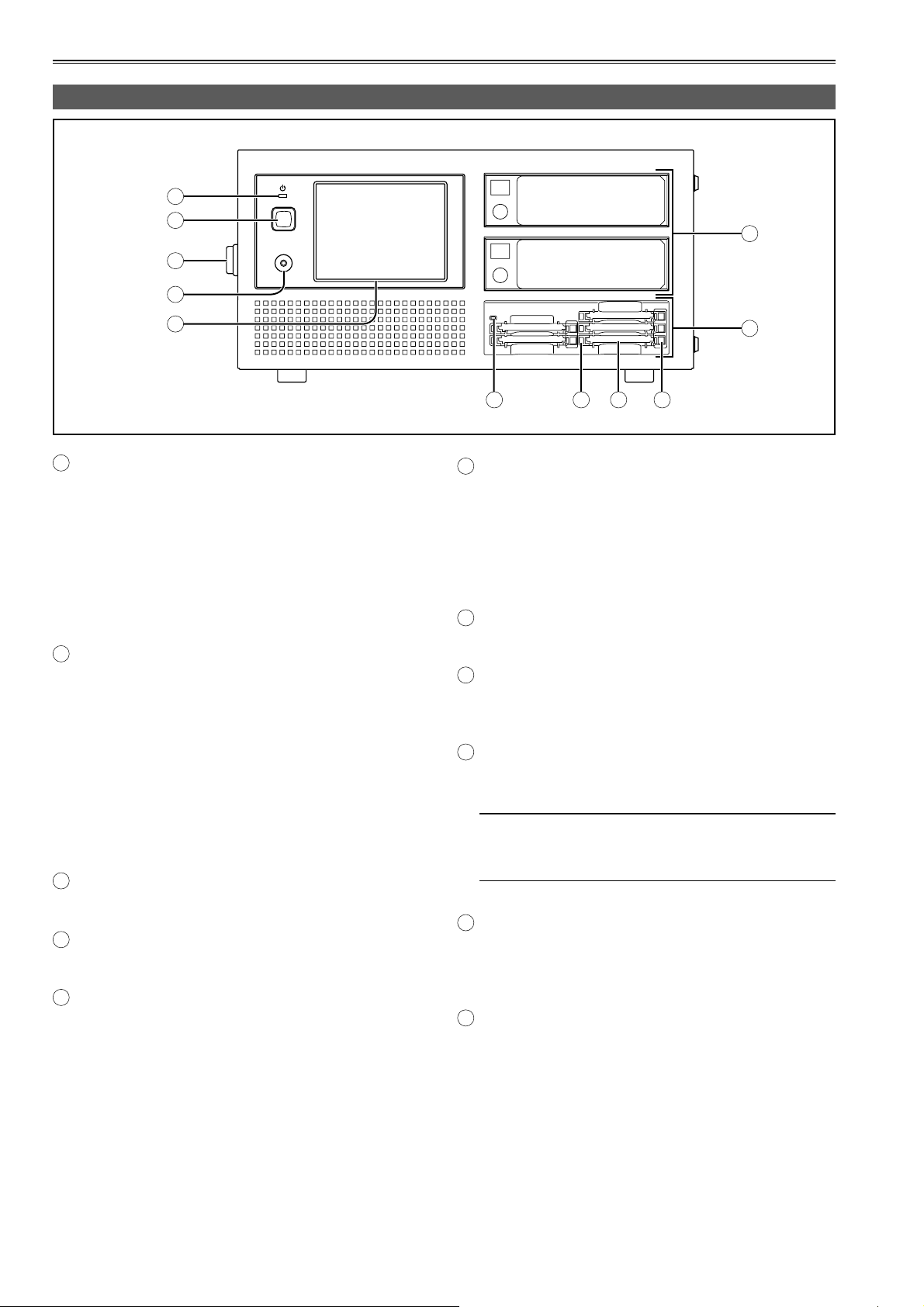
Front Panel
A
B
HEADPHONES
C
D
HDD1
HDD2
F
E
A
Front POWER LED
Lights when the unit is ON.
When the LED goes off and the rear POWER
switch is ON, electric power is still consumed.
Always turn the rear POWER switch OFF when the
battery is not used.
When an external DC power supply is used,
standby power will continue to be consumed so set
the rear POWER switch to OFF.
Front POWER button
B
This button is used to start up the unit and shut it
down.
When it is at the OFF setting:
The unit starts up when the front POWER
button is pressed.
When it is at the ON setting:
The unit shuts down automatically when the
front POWER button is pressed. After the unit
has shut down, set the rear POWER switch to
OFF.
C
Grips
This is the handle for carrying the unit.
HEADPHONES jack
D
Use mini-jack HEADPHONE.
LCD panel with touch panel
E
All the operations are done on the touch panel
except power ON and OFF.
G
H IJ K
5-inch bay units used to install the HDD
F
You can install the HDD (SATA) which you
purchased with the 5 inch bay unit.
For details on the installation method and the
HDDs which can be used, refer to the procedure
described separately, and proceed with the
installation. (page 9)
P2 Drive
G
The P2 drive has been installed.
Power Indicator
H
This indicator lights up in green when the P2 drive
is running.
Status Indicator
I
This indicator blinks in green during access to a P2
card.
Do not remove the P2 card during access of the
card, otherwise files may be corrupted, or the P2
card may fail.
Card Slots
J
The P2 drive’s card slots are designed for P2 cards.
The P2 drive does not operate with cards other
than P2 cards.
EJECT Button
K
To remove a P2 card, press this button so that the
button pops out, then press it in again.
6
Page 7
Control reference guide (continued)
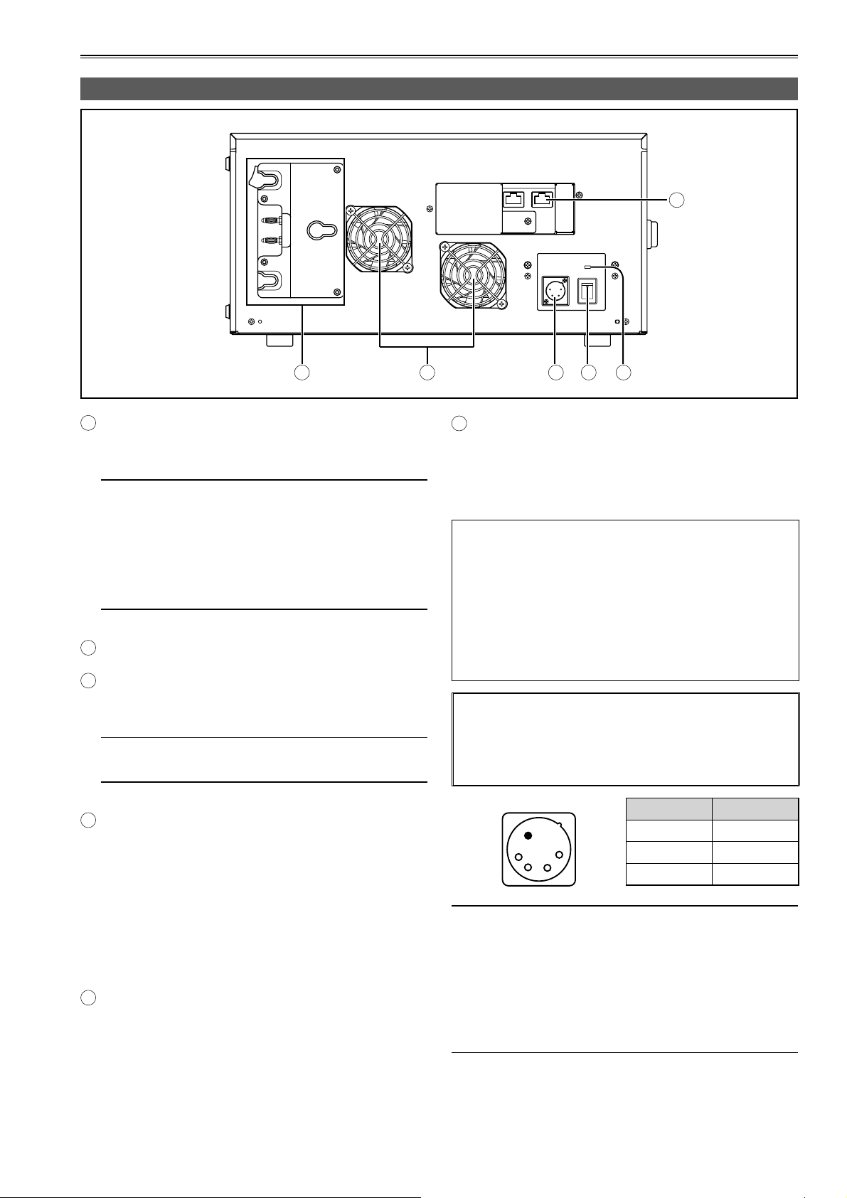
Back Panel
1GBASE-TX
12
LAN
DC IN
F
POWER
ON
OFF
A
A
Battery holder
You can install the battery directly if it is compatible
with Anton Bauer battery holders.
• Charge the battery with the battery charger before
using it. (For details on the charging methods,
refer to the operating instructions concerned.)
• When replacing the battery plate or installing the
V-mount type adapter plate, consult your dealer.
• When installing the battery plate, take care not to
sandwich or pinch the connecting wires.
Cooling fan
B
C
DC-IN connector
This DC-IN connector (XLR 4 pin) is used with an
external DC power supply.
Use an external DC power supply with a rated
value of 100 W or more.
BCD
LAN connector
F
E
These LAN connectors support speeds of 1000,
100 and 10 Mbps.
Please set the IP address in GUI of this unit.
(page 38)
● Use of external DC power supply
Make sure that the output voltage of the external DC
power supply meets the rated voltage of the unit before
connecting the power supply.
Inrush current occurs when the unit is turned on,
and insufficient power at this time may damage the
unit. Thus, we recommend using an external DC
power supply rated at least 100 W. Use the DC cable
recommended for the external DC power supply.
• When using an external power supply other
than the AC adapter, check the DC IN socket pin
information to ensure correct polarity. If a +12 V
power supply is accidentally connected to the GND
terminal, this could cause a fire or personal injury.
Rear POWER switch
D
Use this switch to turn the power ON or OFF when
an external DC power supply or battery is used.
• When the switch is ON, the power (about 2W) is
still consumed in idle state. Always turn the power
OFF when the unit is not used.
• If the switch is set to OFF during HDD operations,
it may cause HDD failure. Set the switch OFF after
normal shutdown.
Rear POWER LED
E
Lights when the rear POWER switch is ON.
DC IN
Pin No. Signal
1 GND
4
1
2
3
2, 3 -
4 +12 V
• When both the battery and the external DC power
supply are connected, power is supplied from the
external DC power supply. The battery can be
removed or mounted while using an external DC
power supply.
• When using an external DC power supply, make sure
you turn on the external DC power supply before
turning on the unit’s power switch.
7
Page 8
Power Supply
A battery or external DC power supply can be used as
the power supply for the unit.
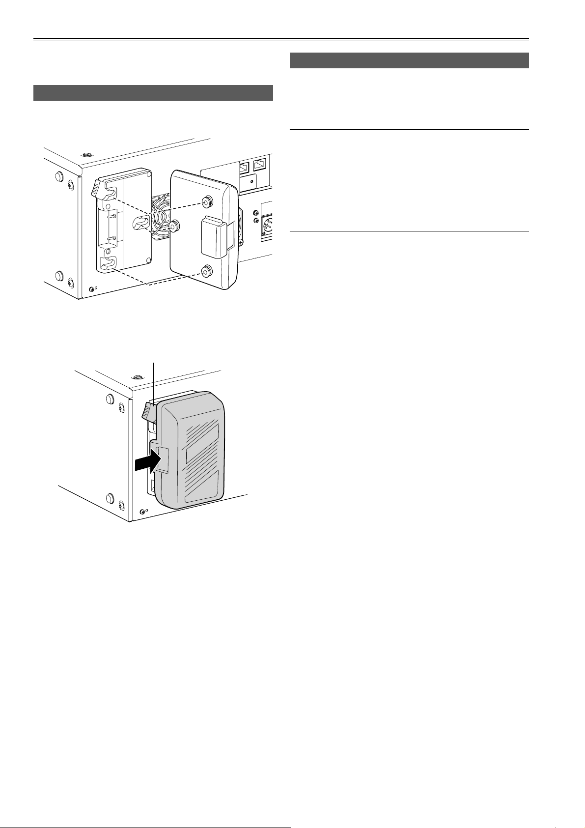
Mounting the Battery
1 Mount an Anton/Bauer battery.
Anton/Bauer Battery
2 Insert the battery and slide it in the direction
of the arrow.
Release lever
Removing the battery
Completely push down and hold the release lever
on the battery holder. Then, slide the battery in the
opposite direction to the arrow while holding the lever
down.
The following is a list of batteries that have been tested
and verified to work with this unit.
• PROPAC14
• TRIMPAC14
• HYTRON50
• HYTRON140
• DIONIC90
• DIONIC160
3 Set the battery type.
Specify the type of battery on the [Battery] tab of the
"SETTING" screen. (page 41)
8
Page 9
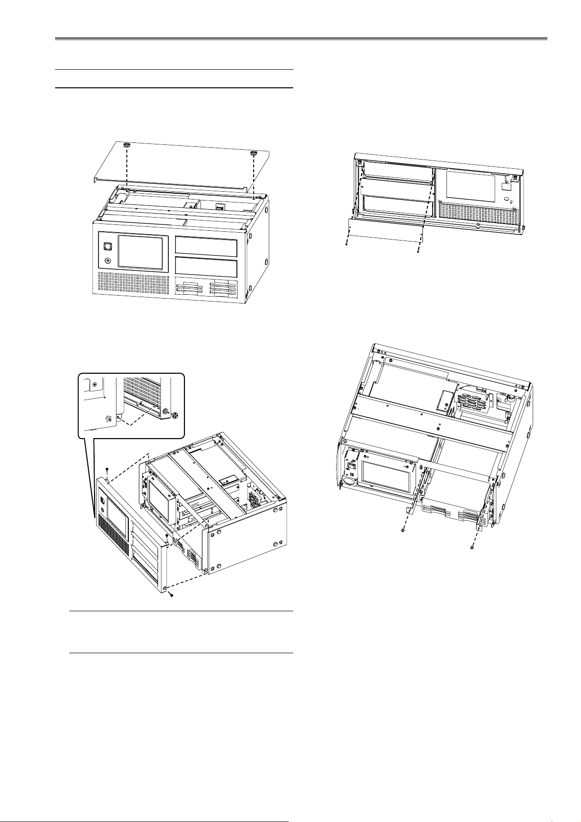
How to install the 5-inch bay units
Follow the steps below to install the 5-inch bay units.
5-inch bay units and HDDs sold separately.
1 Remove the screws (x2) of the top panel, and
remove the top panel.
2 Remove the screws (x2) at the left and right
and also the screws (x2) at the top of the front
panel, and remove the panel. (Total: 4 screws)
3 Remove the screws (x2 each) securing the
5-inch bay unit cover to the front panel, and
then remove the cover.
4 Loosen the left and right anchoring screws of
the 5-inch bay unit brackets, and then remove
the brackets from the main unit.
(x1 screw each at left and right for each 5inch bay unit)
Exercise caution when removing the front panel
since the screw at the top left in the figure above
will catch on the transparent panel.
(Continued on next page)
9
Page 10
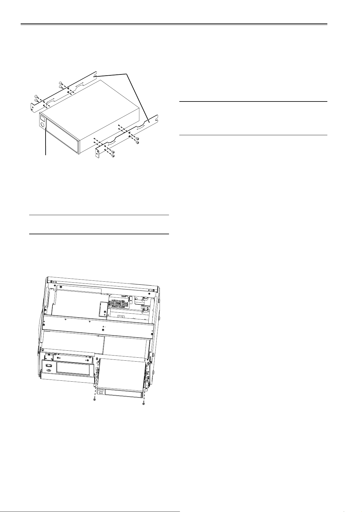
How to install the 5-inch bay units (continued)
5 Install the removed brackets on the 5-inch
bay unit.
(Use the screws provided.)
5-inch bay unit brackets
5-inch bay unit to install
6 Insert each 5-inch bay unit on a shelf, and
then connect the wire harnesses to the power
connector and SATA signal connector on the
back of the bay unit.
8 Put the front panel back in its original
position (using the 4 screws).
9 Close the top panel, and tighten the top panel
screws (x2).
We recommend you to use the following HDD:
Connect IF: SATA-2
Appearance: 3.5-inch internal type
Rotating number: above 7200
For connection details, refer to the operating
instructions for the 5-inch bay units.
7 Anchor the 5-inch bay unit brackets to the
main unit using the left and right anchoring
screws.
10
Page 11
For better performance
This unit is constructed to allow the HDDs to be
installed on 5-inch bay units, but its design does not
improve the HDD drop resistance or impact resistance
performance. Remember to take extra care when
handling the bay units.
• The 5-inch bay units are not packed with the storage
unit. Give due consideration to the applications
for which they will be used, obtain bay units with a
sufficient shock and vibration resistance, and install
them.
Shock resistance and vibration resistance
There are cushions on the legs to absorb the vibration.
However, please understand that no guarantee against
damage or failure.
Handling HDDs
The unit is designed for use with typical HDDs
installed. To minimize any risks associated with
HDD damage, loss of data on HDDs, or interrupted
operation, refer to the HDD user manual for
information on installation and use.
• When moving the unit, after setting the rear POWER
switch to OFF be sure to wait until the HDDs stop
rotating (about 2 minutes) before moving the unit to
avoid subjecting the unit to shock or vibration.
(After the unit is turned OFF, HDDs continue spinning
from inertia for a while.)
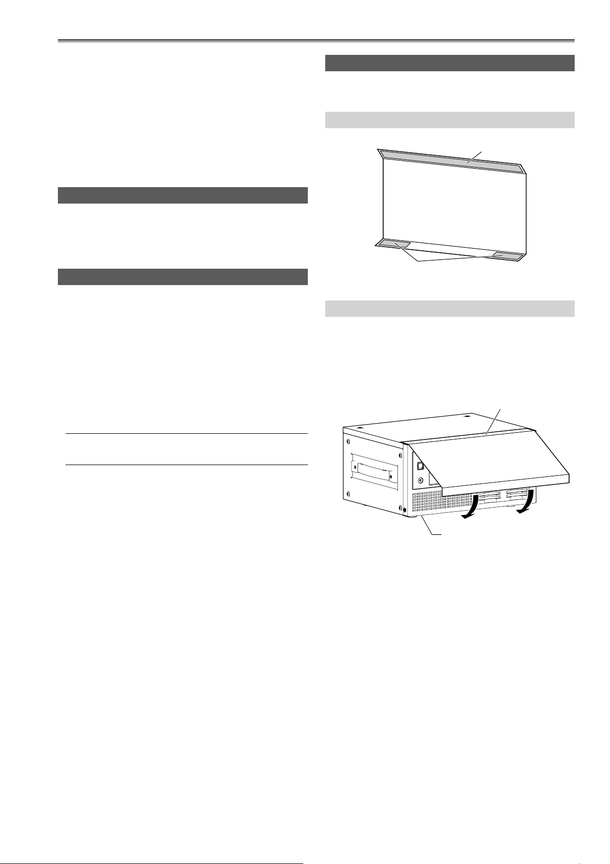
Moving the unit
When moving the unit, protect the front panel with the
front cushion.
Structure of front cushion
Magnet
Surface fasteners
(with adhesive tape)
Installation method
1 Attach the magnetic surface of the front
cushion to the upper area of the unit's front
panel, and decide on where the surface
fasteners will be mounted.
Attaching the magnet
Before moving the storage unit, be absolutely sure to
press the EJECT buttons and set it to in position.
Deciding on where the
surface fasteners will be
mounted.
2 Peel off the separator of the adhesive tape,
and adhere the cushion to the lower area of
the front panel.
(Continued on next page)
11
Page 12
For better performance (continued)
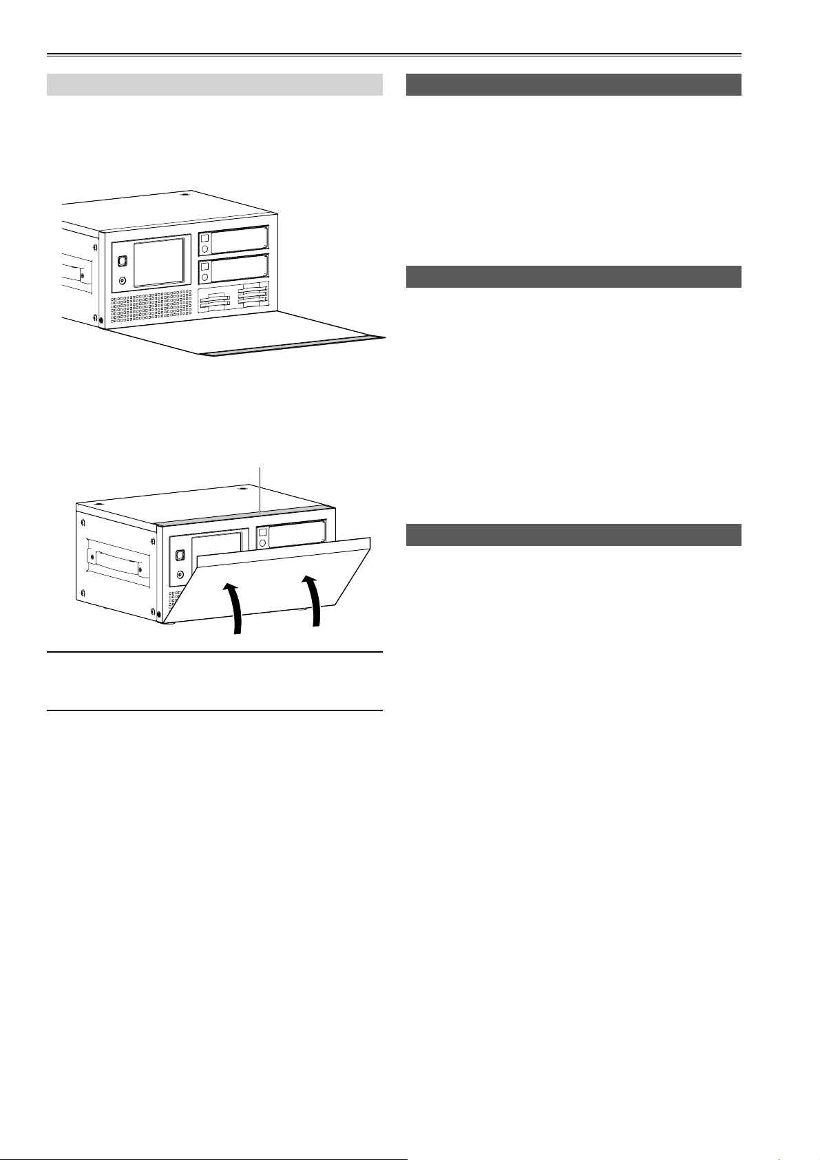
Operation
1 As shown below, attach the surface fasteners
of the front cushion to the bottom of the front
panel.
2 Lift the front cushion and attach it to the top
of the front panel using the magnet.
Place the front cushion magnet
here to secure the cushion.
Recorded data
If P2 cards or HDDs are damaged, data on them will
be lost. Always keep an extra copy of important data
on separate media.
This unit supports mirror (RAID1) operation. Please
consider the worst situation of the operations.
Panasonic is not liable for data lost from P2 card or
HDD failure or other problems, or for other direct or
indirect loss.
Cleaning
Never clean the unit with solvents such as benzene,
thinner, or alcohol.
• Before cleaning, remove the battery or unplug the
unit from the external DC power supply.
• Cleaning the unit with solvents may damage the
external case or cause the paint to peel.
• Use a clean, soft dry cloth to wipe away dust or dirt.
If the unit becomes quite dirty, wipe it with a cloth
dampened in diluted neutral detergent after wringing
the cloth well. Use a dry cloth to wipe it dry.
• If you use a chemically treated dust cloth, follow the
precautions for use.
Before moving the unit, remove the HDDs.
(HDDs may be damaged if the unit is moved with these
drives left in place inside the unit.)
Handling the touch panel
Do not press pointed objects, hard metallic objects, or
objects such as pencils or ballpoint pens against the
touch panel. This may damage the screen.
• If there is any oil or other substance adhering to the
surface of the touch panel, it will not be possible to
conduct operations properly.
• To clean the touch panel, wipe it with a soft cloth.
Do not use benzene, thinner, or similar substances.
12
Page 13
For better performance (continued)
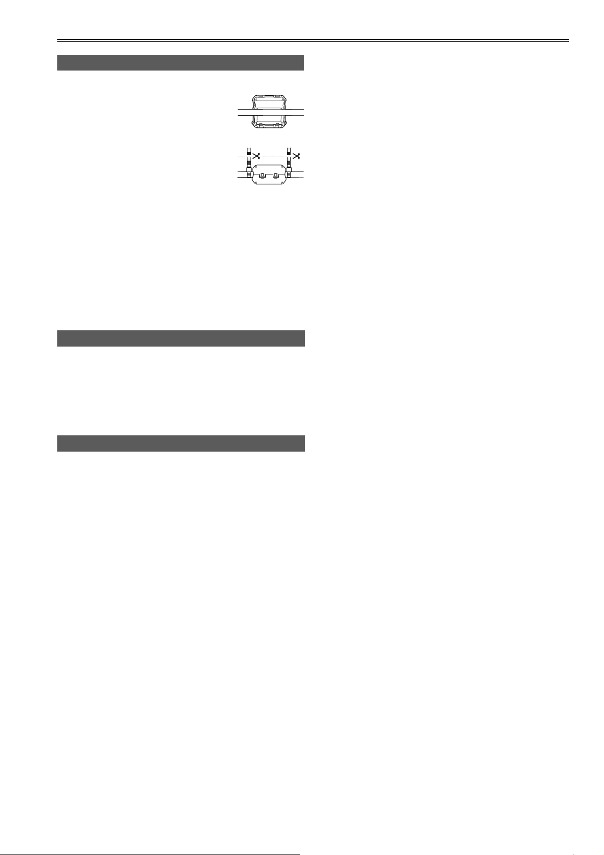
Precautions when connecting the LAN cable
• When connecting the unit to a computer using a LAN
cable, attach the two ferrite cores
(included) on the LAN cable, one
5–10 cm from the computer LAN port
and the other 5–10 cm from the LAN
port on the unit.
Failure to attach ferrite cores could
cause interference with nearby
equipment.
• After attaching the ferrite cores as
shown at right, close them until they click and lock
into place.
• If a ferrite core moves along the cable and cannot
be fixed in place, attach binders on both sides of the
ferrite core to immobilize it.
Cut the binders with scissors to adjust the length.
• Handle ferrite cores with care. Dropping or subjecting
the cores to impact may break them in two.
• Always use a shielded LAN cable.
Use of external DC power supply
Use an external DC power supply rated at 100 W or
more.
Read the DC power supply user manual carefully
before use.
Always use a shielded DC cable.
Battery pack
Use a battery rated at 100 W or more. Read the
battery user manual carefully before use.
13
Page 14
Basic operations
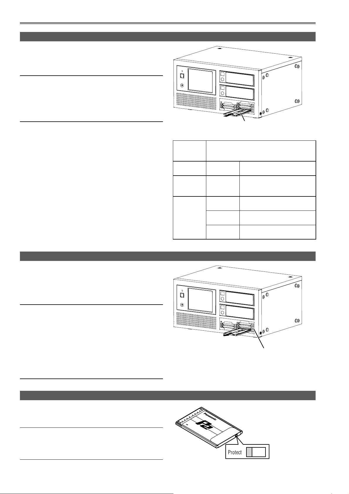
Inserting P2 card
When inserting a P2 card into the P2 card slot of the
P2 drive provided in the unit, be absolutely sure to
position the P2 card parallel to the slot and insert it
straight into the drive.
• Forcing cards in the slot at an angle may damage P2
card, P2 Drive or this unit.
• To prevent cards from falling out, protect the unit
from dust, and reduce the risk of exposure to static
electricity, remove P2 cards before moving the unit.
• Format P2 cards only on a P2 card device.
1 Turn the unit on.
Insert the card with the
logo facing up.
2 Insert a P2 card in a P2 card slot.
When a P2 card is inserted, an icon is displayed on the
control panel.
Also at this time, the P2 CARD ACCESS LED for the
corresponding slot indicates the status of the P2 card.
Ejecting P2 card
1 Press the EJECT button next to the P2 card
slot.
2 After the EJECT button emerges, press it
again to eject the P2 card.
• During access or detection of P2 cards after insertion
(when the P2 CARD ACCESS LED blinks in green),
do not remove the cards. Removing cards during
access may damage them.
• If a P2 card being formatted is removed, it may not
be formatted properly.
• Do not move the unit while the EJECT button is set
to its out position. Doing so may cause damage. Be
sure to press the EJECT button and set it to its in
position first.
P2 CARD
ACCESS
LED
Blinks in
green
Quickly
blinks in
green
Stays off
Being
accessed
Being
recognized
Card not
supported
Incorrect
format
Card not
inserted
Status of P2 Card
Reading is being performed.
The P2 card is being
recognized.
The card is not supported by
the unit. Use another card.
The P2 card is not properly
formatted. Reformat the card.
No P2 card is inserted.
Card recognition standby.
EJECT button
To Prevent Accidental Erasure of P2 Card Content
To prevent the content of a P2 card being accidentally
erased, position the write-protect switch on the P2 card
at [Protect].
Write-protect switchover can be performed while the
card is being accessed (during recording or playback),
but does not take effect until access to the card
ceases.
14
Write-protect
switch
Page 15
Basic operations (continued)
Turning the unit ON and OFF / Exiting
Confirm that the battery or external DC power supply
is firmly connected to the unit. Please refer to the
operation instructions of this unit for the details of
access.
Power ON
After setting the rear POWER switch to ON, press the
front POWER button to turn the unit on.
While the unit is starting up, the startup screen
appears on the LCD panel display.
About one minute later, the main screen appears. The
unit can now be used.
• The unit will automatically shut down if a low-voltage
error occurs. Switch to another, fully charged battery
or use an external DC power supply.
• When the temperature is below the rating
temperature of HDD, the HDD may be damaged.
Please move the unit to a warmer place and do
not use it until the temperature is melt. When the
temperature is above the rating temperature of HDD,
the HDD may be damaged. Please move the unit to
a cooler place and do not use it until the temperature
is melt. (You can check the HDD temperature on the
screen after startup.)
For the rating temperature, refer to the specifications
of each HDD used.
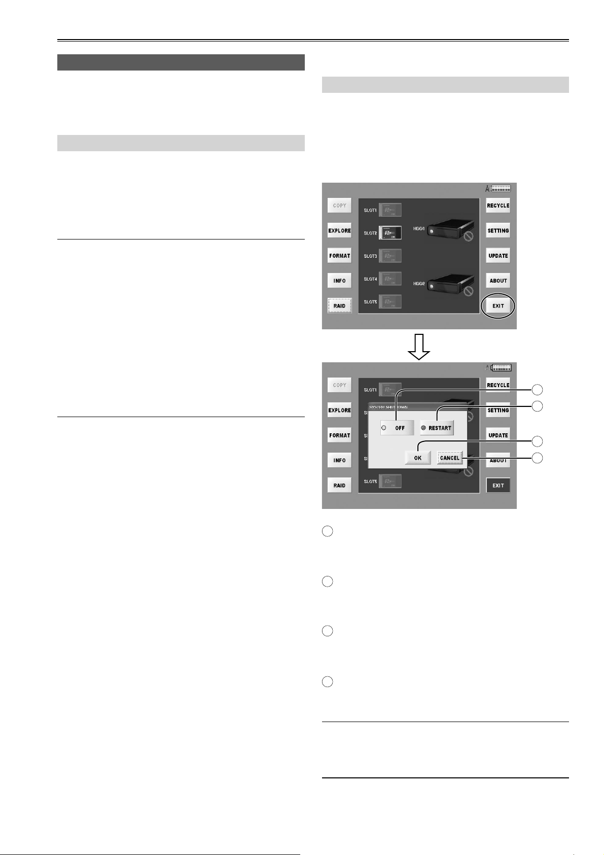
Power OFF
To turn off the power, either press the front POWER
button or the EXIT button on the main screen
displayed after startup, and then press the OFF button
or RESTART button on the shutdown method selection
screen displayed next.
The power is now turned off automatically.
A
B
C
D
A
OFF button
After shutdown is completed, the power is turned
off automatically.
RESTART button
B
After shutdown is completed, the unit is restarted
automatically.
C
OK button
The shutdown method, which was selected on the
shutdown method selection screen, is executed.
CANCEL button
D
The main screen that was displayed previously is
now restored.
Although the front POWER LED goes off, power is still
consumed if the rear POWER switch is not set to OFF.
Also set the rear POWER switch to OFF when the unit
is not used.
15
Page 16

Basic operations (continued)
Power indication
A
B
C
D
E
Functions
Described below are the functions of the buttons which
are provided on the left and right sides of the main
screen.
A
COPY button (page 22)
Copy the clips from P2 cards to HDD.
EXPLORE button (page 25)
B
Explore the clips in P2 cards or in HDD.
FORMAT button (page 36)
C
Format P2 cards or HDD.
INFO button (page 37)
D
Check the current volume of P2 cards or HDD.
RAID button (page 17)
E
Set RAID of HDD.
RECYCLE button (page 35)
F
The clips in the RECYCLE folder and folders can
now be displayed, deleted or restored.
F
G
H
I
J
Power indication
The icon at the top right of the screen indicates the
power supply status as shown by the displays below.
Icon Information
External DC power supply
Battery power supply
(full or nearly full charge)
Battery power supply
(charge level after some use)
Battery power supply
(nearly depleted; Near End:
insufficient voltage)
Switch to another power supply
immediately. Use either a fully
charged battery or an external DC
power supply.
Battery power supply
(depleted; End: insufficient voltage)
SETTING button (page 38)
G
Do various settings.
UPDATE button (page 45)
H
Update the application.
ABOUT button (page 45)
I
Check the current version of application.
EXIT button (page 15)
J
Turn OFF or RESTART.
16
Page 17

Setting the RAID function
The RAID function must be set when a new HDD has been installed.
RAID1 mode: The same data is written simultaneously onto two HDDs.
The data safety is ensured by data redundancy (mirroring).
When HDDs with different memory sizes are combined, the smaller memory size will be used.
JBOD mode: The data is written onto only the specified HDD.
Use this mode when storing large amounts of data.
This screen displays in several TAB screen as the following.
For details, refer to the explanations for each individual tag.
A
A
Basic Information (page 18)
Display the physical and logical device status.
If arbitrary one is abnormal, the “Critical” will
indicate in the Status.
Create RAID (page 18)
B
A JBOD or RAID1 logical device can be prepared.
Proceed with this when:
• Inserting a new HDD and creating a new logical
drive.
• Changing the JBOD setting to the RAID1 setting
or vice versa.
• Installing a new HDD with the JBOD setting
established and using the HDD with the JBOD
setting.
C
Delete RAID (page 19)
This deletes the JBOD or RAID1 logical drive.
Proceed with this when:
• Using an HDD, this was previously used with the
JBOD setting, now with the RAID1 setting.
• Using an HDD, this was previously used with the
RAID1 setting, now with the JBOD setting.
B CD
Rebuild (page 20)
D
This starts and finishes the data rebuilding process.
Proceed with this when either of the following
events has occurred with the RAID1 setting:
• When trouble occurred in one HDD, and the HDD
was replaced.
• When data could not be written on one HDD
during copying because of reason or other.
E
RAID Settings (page 21)
This makes it possible to perform the settings
related to the RAID board.
UNMOUNT button
F
With the power ON, press this button before
removing the HDD.
The indicated HDD is now logically isolated.
After this setting, remove the HDD.
If the HDD is not installed, this button will not be
displayed.
G
CLOSE button
This closes the screen and restores the main
screen.
E
F
G
No guarantees are given for what might happen when
an HDD is installed while the power is on.
Be absolutely sure that the power is turned off before
installing the HDD, and then start it.
17
Page 18

Setting the RAID function (continued)
Viewing basic RAID information
(Basic Information)
The statuses concerning the HDDs used and RAID are
displayed.
A
B
C
A
Physical Drive
The following information about the HDD installed is
displayed.
● Drive Model
Display the HDD product numbers.
Setting up RAID drives (Create RAID)
When RAID is re-set, the data on the HDD will be
deleted so take care before proceeding.
This is used when specifying either JBOD mode with
separate logical drive names for each HDD or RAID1
mode with mirrored HDDs.
This job is required when installing a new HDD.
(In the RAID1 mode)
A
B
C
D
E
(In the JBOD mode)
Port
●
Display the numbers of the ports where the RAID
boards are connected
● Temperature
Display the temperatures of the HDDs
● Capacity
Display the memory sizes of the HDDs
● Status
Display the statuses of the individual HDDs
Logical Drive
B
● Assigned Name
Display the setting names
● Raid Level
Display either JBOD or RAID1
● Capacity
Display the memory size of the HDDs
● Status
Display the statuses
● UNMOUNT button (page 17)
Press this when logically isolating the HDD
before it is unmounted.
If the HDD is not installed, this button will not be
displayed.
A
B
C
D
E
RAID1 button
A
This is used when writing the same data
simultaneously onto two HDDs.
JBOD button
B
Using each HDD as an individual device.
HDD-related information
C
The HDD manufacturer name, product number, and
disk size will be displayed on the right-hand side of
the button.
In JBOD mode, the HDD may be selected with the
button on the left.
NEXT button
D
This continues settings.
E
CLOSE button
Return to the main screen.
CLOSE button
C
Return to the main screen.
18
Page 19

Setting the RAID function (continued)
Press NEXT button after setting, the confirming screen
will display. Please press OK button.
(In the RAID1 mode)
(In the JBOD mode)
Deleting RAID drives (Delete RAID)
When switching between RAID1 and JBOD or
otherwise changing the RAID level, delete the logical
drive which is currently set.
When the RAID level is re-set, the data on the HDD
will be deleted so take care before proceeding.
A
B
When HDDs of different capacities have been set as
RAID1, the smaller size of the two installed HDDs is
displayed in Logical Drive Size.
Please press OK button in the further confirming
screen.
When the OK button on the reconfirmation screen is
pressed, all the data on the HDD is deleted. Make
sure that you do not need the data before pressing this
button.
A
HDD-related information
● Select
The button will flash green when selected.
Assigned Name
●
Display the RAID board connection location and
RAID level.
● Array ID
Displays RAID control number.
● Capacity
Displays RAID disk capacity.
● Status
Displays operating conditions.
CLOSE button
B
Return to the main screen.
The HDD is indicated as a theoretical device. Select
the device you want to delete and press OK button, a
confirming message will display.
Press the OK button when a message is displayed
after RAID initialization. The unit can now be used as a
RAID drive.
Press OK button and the selected theoretical device
will be deleted from the theoretical device list.
After the finished message is displayed, Press the OK button.
19
Page 20

Setting the RAID function (continued)
Rebuilding RAID drives (Rebuild)
When data rebuilding is necessary or during
the rebuilding process, either “Need Rebuild” or
“Rebuilding” is displayed under the HDD icon on the
main screen.
Press the RAID button in this status, and select
the [REBUILD] tab. The screen shown below now
appears.
A
When the STOP button has been pressed, a
confirmation message such as the one shown
below is displayed.
To stop the rebuilding, press the OK button; to
cancel the stopping, press the CANCEL button.
• If an HDD has been replaced due to trouble while
setting RAID1, rebuilding from a trouble-free HDD
must be undertaken for mirroring purposes.
• When the automatic rebuilding can not work normally
as usual, please follow the indication to rebuild in
this screen. Automatic rebuilding is not initiated if
[Disable] is set for the Automatic Rebuilding Status
on the RAID settings screen.
• The status and progress are indicated during the
rebuilding process. Note that it takes about 2 hours
to rebuild a 500 GB HDD. Do not unplug the external
DC power supply during this time.
(When rebuilding is in progress)
A
HDD-related information
● Array Name
Display name of logical drive.
Rebuild Status
●
Display Rebuild Status.
If “Need Rebuild” is displayed, rebuild is required.
If “Rebuilding” is displayed, rebuild in is progress.
● Percentage
Display rebuild completion ratio (%). (Rebuild is
complete when this ratio reaches 100 %.)
START button
B
Start the rebuilding process.
When “Need Rebuild” was displayed, this button is
shown with black text.
B
C
D
C
STOP button
Stop the rebuilding.
CLOSE button
D
Return to the main screen.
20
Page 21

Setting the RAID function (continued)
RAID Settings
The basic processing of the RAID1 function is set.
A
Rebuild Rate
Set the rebuilding rate.
While the rebuilding process is underway, both
playback and access from an external source via
the LAN can be performed at the same time.
When rebuilding and playback or rebuilding and
external access have been performed at the same
time, the rate of not only the rebuilding but the
playback or external access as well will be reduced.
Automatic Rebuilding Status
B
● Enable button
A
B
C
D
E
Rebuild automatically.
● Disable button
Rebuild manually.
To initiate rebuilding, press the START button of
the Rebuild tab.
C
Buzzer Status
These control the ON/OFF statuses of the BUZZER
on the RAID board. This BUZZER sounds when
trouble has occurred on the RAID button.
● Enable button
Buzz when HDD is plugged.
● Disable button
Be quiet all the time.
APPLY button
D
Register currently set details.
For details on the rates provided by the LOW
button, MEDIUM button and HIGH button, refer to
the table below.
LOW
button
Rebuilding time
Playback frame
skip amount
* The rebuilding time is about 2 hours for 500 GB.
The rebuilding times given are estimates only
and will vary depending on the HDD used and
operating environment.
Slow Normal* Fast
Low
number of
frames
MEDIUM
button
Middling
number of
frames
HIGH
button
High
number of
frames
E
CLOSE button
Return to the main screen.
21
Page 22

Copying
The data on the recorded P2 cards is copied onto the HDD.
The data is copied from the P2 card onto the HDD on a card by card basis or clip by clip basis (see page 27).
Use the copying method that best suits the application concerned.
Copying entire cards
Two copy modes are available when copying entire
cards, as follows.
• Manual copy mode: Data is copied after inserted P2
cards are selected.
• Auto copy mode: Data is automatically copied from
inserted P2 cards.
To switch between auto and manual copy modes and
complete the settings, access the [Copy Settings] tab
on the "SETTING" screen (page 39).
Manual copy mode
Insert the P2 card to copy and press the COPY button
on the main screen. Next, complete the copy settings
as follows.
(In the RAID1 mode)
A
C
(In the JBOD mode)
A
B
D
B
C
A
SOURCE
Select the P2 card to copy.
(Multiple cards in slots 1–5 can be selected.)
DESTINATION
B
Select the destination for copying.
In RAID1 mode, there is only one destination
available, and there is no need to select it.
C
START button
Start manual copying.
CLOSE button
D
Return to the main screen.
D
22
Page 23

Copying (continued)
Manual copy mode (continued)
Take the steps below for manual copying.
1
In SOURCE, select the P2 card to copy.
(More than one card can be selected
using SLOT1 to SLOT5.)
2
In DESTINATION, select the destination
for copying.
(HDD1, HDD2 for the JBOD mode; no
destination selected for the RAID1
mode)
3
Press the START button.
Copying will begin.
A confirmation screen will be displayed for any
cards that have already been copied.
Press the YES button to proceed to a screen
displaying the current copying progress (page 24).
Press the NO button to return to the main screen.
If you press CLOSE button in this screen, you will
go back to the main screen.
In RAID1 mode, there is only one destination available,
and there is no need to select it in step 2.
Auto copy mode
In auto copy mode, a popup screen is displayed when
a P2 card is inserted.
A
A
Copy All button
Copy the currently inserted card.
Copy New button
B
Copy new cards only.
C
Cancel button
Return to the main screen without automatic
copying.
In this mode, the unit detects when a card is inserted.
If no other card is inserted within 10 seconds, data
is automatically copied from the inserted card to the
designated HDD.
After copying, it will copy automatically when inserting
a new P2 card.
BC
• Multiple P2 cards may not be recognized if inserted
at the same time. In this case, automatic copying is
not performed.
Try reinserting the P2 cards.
• Auto copy will not be executed even when the unit is
started or restarted while a P2 is inserted.
• The data is not copied automatically if the amount of
recordable memory on the HDD is less than that on
the P2 card.
• If a copied card has been inserted into the HDD while
ON is set for the copied card check function (Card
Check), auto copy will not be executed.
To re-copy an already copied card, press the Copy All
button.
23
Page 24

Copying (continued)
Once copying starts in manual or auto copy mode, the
sequence of processing is as follows.
The copying state and the progress of each card
displays on the screen.
A
BC
A
Status displays
The meaning of the status indicated is described
below.
● Copying
The contents are being copied to this destination.
Confirmation after copying
The results of copying can be checked on the copy
confirmation screen displayed after copying is finished.
By pressing the CONFIRM button, the copying is
finished, and when the FINISH button on the copy
state display screen is pressed, a screen on which to
confirm the previewing of the copied data is displayed.
● Waiting
Copy standby state.
● Verifying
State in which copying is completed and the data
on the HDD is being compared with the data on
the P2 card.
● NS
The destination is not selected now.
● NC
No card inserted.
FINISH button
B
Enter the completion of the copying process.
C
CANCEL button
Cancel copying in progress.
• If copying is cancelled before completion, all copied
data will be erased.
• Copying cannot be canceled while verifying is
underway.
If the YES button is pressed on the confirmation
screen, the EXPLORE screen which displays the
folders and icons on the HDD will appear.
If the NO button is pressed instead, the main screen is
restored.
24
Page 25

Checking the clips in P2 card/HDD
Open EXPLORE screen, you will find that data in different device displays in different ways.
P2 card : Thumbnail HDD : Folder
A
HI
J
L
M
N
O
P
B CD
To display the clips on the HDD, double-click the folder for the day when the data was copied.
All thumbnails in the folder are shown.
Device selection button (page 29)
A
Select the device displays in the thumbnail screen.
The selected device will be displayed on the button.
SELECT ALL button / UNSELECT ALL button
B
Press SELECT ALL button to select all the clips in the
same time. The display changes to [UNSELECT ALL].
When the UNSELECT ALL button is pressed, the
selected status is cleared and the button label
changes to [SELECT ALL].
SELECT button / UNSELECT button
C
Move the cursor to select the clip you want, and
press SELECT button to make it selected. When
you move the cursor to the clip which is selected,
the button label changes to [UNSELECT]. Press it
and make the clip in unselected state.
When the button is double-clicked, its display is
switched between SELECT and UNSELECT.
COPY button (page 27)
D
Select the file (blue framed) and press this button,
the copying destination will be displayed.
This function button is not displayed when HDD is
selected.
E FKG
PLAY button (page 32)
F
Start the application to play the selected clip (blue
framed).
PROP button (page 28)
G
Press this button, the property of the clip (yellow
framed) in cursor will be displayed.
FILTER button (page 30)
H
You can select the combination displayed in
thumbnail screen.
SORT button (page 31)
I
Change the displaying order of the selected clips.
Slot number/HDD state (page 31)
J
Indicates the device containing the clip by the
cursor (yellow framed).
Clip number
K
Clip numbers will be ordered from top-left to
bottom-right, starting with 0001.
Clips will be similarly re-numbered from the top-left
if the SORT function is used to change their order.
Q
T
S
R
DELETE button (page 27)
E
Press this button will delete the selected clips (blue
framed).
(Continued on next page)
25
Page 26

Checking the clips in P2 card/HDD (continued)
P2 card : Thumbnail HDD : Folder
A
HI
J
L
M
N
O
P
B CD
Shot marks
L
These are displayed on the clips which have been
provided with shot marks.
The clips can be filtered depending on whether they
are provided with shot marks or not. (page 30)
Icons
M
: Displayed for high-definition clip.
: Displayed if certain clips from a sequence are
missing.
: This is displayed when something is wrong
with a clip.
Clips with this mark cannot be copied or
played back.
CREATE DATE
N
The creation time of the clip (yellow framed) where
the cursor is positioned is displayed here.
E FKG
T
Q
V_FORMAT
P
The recording signal format of the clip (yellow
framed) where the cursor is positioned is displayed
here.
OPEN button
Q
Select the folder you want to view and press this
button to open it.
CLOSE button
R
P2 cards:
Close the thumbnail screen and go back to the
folder displaying screen.
HDDs:
Return to the main screen.
Power supply indicator (page 16)
S
Shows the power supply status.
S
R
DUR.
O
The recording duration of the clip (yellow framed)
where the cursor is positioned is displayed here.
26
Folder
T
The date on which copying was started is displayed
as the folder name.
Page 27

Checking the clips in P2 card/HDD (continued)
Copying individual clips (COPY)
This function button is not displayed when HDD is
selected.
When the COPY button is pressed after the file has
been selected (blue framed) on the EXPLORE screen,
the copy destination selection screen appears.
(In the RAID1 mode)
(In the JBOD mode)
Deleting individual clips (DELETE)
When the DELETE button is pressed on the EXPLORE
screen, the selected clip (blue framed) can be deleted.
“DELETE CLIP NUMBER” displays the number of clips
selected.
A
You can do deleting operation according to the
following methods.
RECYCLE button
A
Move the clips to RECYCLE folder.
If necessary, the clips can be restored. (Page 35)
However, this button cannot be used with P2 cards.
ERASE button
B
Delete from HDD completely.
B
Select the copying destination and press OK button to
start the copying.
If Verify = ON button is set in the SETTING screen
(page 39), it will Verify automatically after the copying.
After the copying (or Verifying) is completed, the
completion confirmation screen appears.
If the YES button is pressed on the confirmation
screen, the EXPLORE screen which displays the
folders and icons on the HDD will appear.
If the NO button is pressed instead, the main screen is
restored.
Select the deleting method and press DELETE button,
the clip will be deleted.
Press CANCEL button, you will go back to the
thumbnail screen without deletion.
27
Page 28

Checking the clips in P2 card/HDD (continued)
Viewing clip properties (PROP)
When the PROP button is pressed on the EXPLORE
screen, the properties of the clip where the cursor is
located (yellow framed) will be displayed.
A
B
C
D
E
F
Clip properties
A
Items are displayed as follows:
● CLIP NAME
Displays name of clip.
NEXT button
D
The property of the one chip after the one in cursor
will be displayed.
E
EDIT button
When this button is pressed, the Meta Data Edit
screen (with the items shown on the right) is
displayed, and the Meta Data can be changed.
CLOSE button
F
Close the property screen and go back to the
thumbnail screen.
The cursor moves to the thumbnail displayed last
on the property display screen.
Editing Meta Data
When any of the items to be edited on the Meta Data
Edit screen is clicked, the letters of the EDIT button
turn black only for those items which can be changed.
● START TC
Displays time code at beginning of clip.
● START UB
Displays Users Bit at beginning of clip.
● CREATE DATE
Displays date of recording.
● CREATE TIME
Displays time of recording.
● DURATION
Displays duration of recording.
● V_FORMAT
Displays video compression format.
● CODEC CLASS
Displays compression ratio.
● FRAME RATE
Displays number of frames.
● ASPECT RATIO
Displays clip aspect ratio.
A
EDIT button (page 29)
A
The soft keyboard is displayed.
For details on the soft keyboard, refer to page 29.
Meta Data of clips created using the Edit Clip
function of other P2 devices cannot be edited.
OK button
B
After overwriting the Meta Data with the currently
displayed Meta Data, the Property screen is
restored.
BCD
Thumbnails
B
Shows a thumbnail of the clip for which you are
viewing property information.
PRE button
C
The property of the one chip before the one in
cursor will be displayed.
28
CANCEL button
C
The Meta Data remains unchanged, and the
Property screen is restored.
APPLY button
D
The Meta Data is overwritten with the currently
displayed Meta Data.
Page 29

Checking the clips in P2 card/HDD (continued)
Select listed devices
soft keyboard
A
GH
(device selection buttons)
When the Device Selection Button is pressed on the
EXPLORE screen, the devices to be displayed on the
thumbnail screen are selected.
B
C
D
MODE
A
The names of the modes corresponding to the
items are displayed here.
• Alphanumeric characters can be inputted when
[Character String Mode] is displayed.
• Only numbers can be inputted when [Number
Mode] is displayed.
B
Input column
Inputted alphanumeric characters are displayed.
ESC button
C
This restores the original Meta Data screen.
CAPS LOCK button
D
This switches the letters between the upper case
and lower case.
E
BACKSPACE button
This deletes the character in front of the character
where the cursor is located.
ENTER button
F
This enters the currently displayed data.
G
← button
This moves the cursor in the input field toward the
left.
A
E
F
E F
ALL SLOTS button
A
This displays all the slots.
B
ALL HDDS button
This displays all the HDD.
This display will not appear when in RAID mode.
HDD1 button / HDD2 button / RAID1 button
C
HDD will be selected for each when in HDD mode.
This button will be displayed as [RAID1] when in
RAID mode.
SLOT1 button ~ SLOT5 button
D
These are used to select and display the slots.
OK button
E
Thumbnails are displayed in the case of P2 cards.
Folders are displayed in the case of the HDDs.
CANCEL button
F
Close this screen and return to the EXPLORE
screen.
B
C
D
→ button
H
This moves the cursor in the input field toward the
right.
Input instructions are as follows.
1. To enter letters, press keys on the on-screen
keyboard.
2. To confirm input, press the ENTER button.
Select devices as follows.
● P2 cards
Select the P2 card slot you require (either the ALL
SLOTS or individual SLOT (1-5) buttons), and then
press the OK button.
● HDDs
Select the HDD you require (from among the ALL
HDDS, HDD1 or HDD2, or RAID1 button), and then
press the OK button.
29
Page 30

Checking the clips in P2 card/HDD (continued)
Selecting clips to display (FILTER)
When the FILTER button is pressed on the EXPLORE
screen, the combinations to be displayed on the
thumbnail screen can be selected.
A
B
C
D
E
G H
A
ALL CLIPS button
All the clips of the displayed devices are displayed.
SAME FORMAT button
B
This displays only those clips recorded in the same
format as the clip (yellow framed) where the cursor
is positioned.
SELECTED CLIPS button
C
This displays only the clip (blue framed) which is in
the selected status.
F
After entering the keyword, press the APPLY button
and the OK button to proceed with filtering.
If there are no clips which match the keyword
concerned, a message indicating that no such clips
exist is displayed.
If clips matching the keyword exist, only the thumbnails
of those clips are displayed.
Multiple keywords can be selected at once.
Press the CANCEL button to close the “keyword input”
screen and return to the previous screen.
Meta Data items
The following filtering processes may be performed for
Meta Data items:
● Reporter button
Filter by reporter.
● Purpose button
Filter by coverage target.
● Object button
Filter clips by content.
● ProgramName button
Filter by program name.
D
Marked Clips
This displays only the clips provided with shot marks.
E
Unmarked Clips
This displays only the clips not provided with shot marks.
F
Meta Data items
Only the clips corresponding to the keyword which
was input in the selected item are displayed.
G
OK button
Filter by selected or preset conditions.
H
CANCEL button
Close FILTER selection screen without performing
filtering process.
When any of the Meta Data item buttons is pressed,
the “keyword input” screen is displayed.
Input field
● SceneNo. button
Filter by scene number.
● UserClipName button
Filter by clip name (set by user).
● PlaceName button
Filter by coverage location.
● Source button
Filter by input source.
● Creator button
Filter by creator.
● Shooter button
Filter by cameraman.
● Copy Time button
Filter by time of copying to this unit.
● Rec. Date button
Filter by date of recording.
To input a keyword, click the input field, input the word
using the soft keyboard screen, and enter it.
For details on the soft keyboard, refer to page 29.
30
Page 31

Checking the clips in P2 card/HDD (continued)
Changing how clips are listed (SORT)
Change the displaying order of the selected clips.
The following display appears when the SORT button
is pressed on the EXPLORE screen.
A
B
C
D
EF
START TC button
A
This button rearranges the clips in the START TC
order. Each time it is pressed, the start TC of the
clips is switched between ascending or descending
order.
CLIP NAME button
B
This button rearranges the clips in the CLIP NAME
order. Each time it is pressed, the clip names are
switched between ascending or descending order.
Viewing slot numbers and HDD status
This indicates the P2 card or HDD containing the clip
where the cursor is positioned.
This displays the P2 card slot number or HDD
containing the clips, in yellow.
If the recording of a clip extends over a multiple
number of P2 cards, all the numbers of the slots where
the P2 cards with the recorded clip are inserted are
displayed.
CREATE DATE button
C
This button rearranges the clips in the CREATE
DATE order. Each time it is pressed, the dates
of the clips are switched between ascending or
descending order.
COPY TIME button
D
This button rearranges the clips in the COPY TIME
order. Each time it is pressed, the copy times
of the clips are switched between ascending or
descending order.
OK button
E
This initiates the rearrangement of the clips as per
the condition selected.
CANCEL button
F
This cancels the rearrangement of the clips, and
restores the EXPLORE screen.
The numbers of the slots where the P2 cards are
inserted are displayed in white.
One HDD mark indicates a RAID1 configuration, and
two HDD marks indicate a JBOD configuration. As with
P2 cards, the HDD containing the clip where the cursor
is positioned is displayed.
31
Page 32

Playing the clips
The PLAYER application starts up when the PLAY button is pressed after the clips to be played have been
selected on the EXPLORE screen.
O
L
M
N
A
B C D
A
(PREV button)
Each time this button is pressed, play jumps to the
start of the previous clip.
B
(REW button)
When this button is pressed, clips are played
rapidly in reverse, skipping frames, at the playback
speed specified on the SETTING screen (page 33).
C
(PLAY button)
Press this button to play the clip.
D
(PAUSE button)
Press this button to stop playing temporarily.
E
(FF button)
When this button is pressed, clips are played
forward rapidly, skipping frames, at the playback
speed specified on the SETTING screen (page 33).
EF
I
J
K
L
M
N
G
P
H IJ K
VOLUME
The slider is slid by operating the + and - buttons
on the left.
SETTING button (page 33)
Set the speed in the REW and FF.
CLOSE button
Stop playing clips in PLAYER and go back to
EXPLORE screen.
TIME CODE
Indicate the time code of the clip being played now.
CLIP NAME
Indicate the name of the clip being played now.
DURATION
Indicate the duration of the clip being played now.
F
(NEXT button)
Each time this button is pressed, play jumps to the
start of the next clip.
In the final clip, press the button again to jump to
the end of the clip.
G
(Volume Up button)
This increases the volume level of the sound.
H
(Volume Down button)
This reduces the volume level of the sound.
32
Slider
O
You also can move the slider in the bottom of the
screen to move to the designated position.
Power supply indicator (page 16)
P
Shows the power supply status.
• Black burst may occur between clips. This does not
indicate a mechanical problem.
• Because playback relies on software codecs, some
frames are skipped. Real-time playback is not
ensured.
Page 33

Playing the clips (continued)
Setting the FF/REW rate
Set the speed in the REW and FF.
When SETTING button is pressed on the PLAYER
application screen, the following screen appears.
A
4Xspeed button
A
Clips are played rapidly while skipping frames at a
speed equivalent to 4 times the normal speed.
8Xspeed button
B
Clips are played rapidly while skipping frames at a
speed equivalent to 8 times the normal speed.
16Xspeed button
C
Clips are played rapidly while skipping frames at a
speed equivalent to 16 times the normal speed.
CLOSE button
D
This restores the PLAYER application screen.
BC D
33
Page 34

Sharing the folders
A shared setting can be established to allow the folders of an HDD selected on the "EXPLORE" screen to be
accessed from another computer.
Please set Network in SETTING screen in advance.
(page 38) Accessing via network will not enable if you
do not set so.
F
G
H
A
SHARE button / UNSHARE button
A
Select the folder and press this button to share.
Select the shared folder and press UNSHARE
button to make it in unshared state.
SHARE ALL button
B
Press this button to share all the folders.
C
UNSHARE ALL button
Press this button to make all the folders in
unshared state.
Sharing is on the basis of individual folders.
DELETE button
D
When this button is pressed, the selected folder can
be deleted. (page 27)
B CD
E
OPEN button
E
Select the folder you want to view and press this
button to open it.
F
In this status, the network is not shared.
G
In this status, the network is shared.
Power supply indicator (page 16)
H
Shows the power supply status.
I
CLOSE button
This closes the EXPLORE screen and restores the
main screen.
I
34
Page 35

Returning the clips in the RECYCLE folder
When the RECYCLE button is pressed on the main screen, the RECYCLE screen is displayed.
The clips in the RECYCLE folder and folders can now be displayed, deleted or restored.
A
SELECT ALL button / UNSELECT ALL button
A
Pressing the SELECT ALL button enables you
to select all clips and folders in the RECYCLE
folder at once. Afterwards, the button is labeled
"UNSELECT ALL."
Pressing the UNSELECT ALL button clears the
selected status of all clips and folders and changes
the button label to "SELECT ALL."
SELECT button / UNSELECT button
B
Move the cursor to desired clips and folders and
press the SELECT button to select them.
The button label changes to "UNSELECT" when
the cursor is moved to selected clips and folders.
Pressing the UNSELECT button clears the selected
status.
When the button is double-clicked, its display is
switched between SELECT and UNSELECT.
B CD
E
ERASE button
C
This completely erases the selected folder and
clips.
Folders and clips, once erased, cannot be restored.
Check carefully if a folder or clip will be needed
before erasing folders and clips.
RESTORE button
D
This returns the selected folder and clips to their
original location.
CLOSE button
E
Return to the main screen.
35
Page 36

Formatting
To format a P2 card or HDD, press the FORMAT button on the main screen. The device selection screen to be
formatted now appears.
B
C
D
A
A
FORMAT SLOTS button
SLOT1 button/SLOT2 button/SLOT3 button/
SLOT4 button/SLOT5 button
These buttons can be used to select the P2 cards
inserted in any slot.
B
FORMAT HDDS button
HDD1 button/HDD2 button/RAID1 button
These buttons can be used to select any of the
HDDs.
START button
C
This starts the formatting.
CLOSE button
D
Return to the main screen.
• Be careful when formatting media or devices.
Formatting will erase all data on P2 cards or HDDs.
• P2 cards cannot be formatted if the write-protect
switch is set to Protect.
The device is formatted by taking the following steps.
1 Select the device and press START button,
the FORMAT confirming screen will display.
2 Press OK button in this screen, the further
confirming screen will display.
3 Press OK button again and begin the
formatting.
Please understand that it can not be canceled
once the formatting begins.
The ending confirming screen will display after
formatting, press OK button to go back to the device
selecting screen.
36
If you press CANCEL button before formatting, you
can go back to the device selecting screen.
An error message is displayed if formatting is not
possible.
All the formats are FAT32. (The largest volume is limited
to 2 TB by the FAT32 format. Please understand it
when you install larger HDD in the future.)
Page 37

Checking the state of all slots
Press INFO button in the main screen, the INFO screen will display.
A
B C
You can check the volume of P2 cards in any slot or
the HDDs. The default volume name is DVCPRO HD.
If you want to check the volume in other format, please
press FORMAT select button on the bottom of the
screen.
A
Slots
Write-protected P2 cards are identified by a ( )
mark next to the slot number.
B
Format select button
This indicates the used memory and total memory
(USED/ALL) in minutes (MIN) for the corresponding
format.
One of the following 5 buttons is displayed.
• [DVCPRO]
• [DVCPRO 50]
• [DVCPRO HD]
• [AVC-I50]
• [AVC-I100]
C
CLOSE button
Close the INFO screen and go back to the main
screen.
37
Page 38

System setting
Press SETTING button to set the system in the main screen.
This SETTING screen is constructed by plural TAB as the following.
For details, refer to the explanations for each individual tag
Configuring network settings (Network)
Set network access of LAN1 as well as LAN2.
A
B
C
Adapter
A
Select rear panel LAN connector. (Page 7)
DHCP
B
This sets the IP address automatically.
The IP address is allocated automatically from the
DHCP server if a DHCP server is available in the
network environment connected.
Specifying the display language (Language)
Select the language you want to use in all the screens.
A
D
E
F
A
displaying in Chinese
B
ENGLISH
displaying in English
APPLY button
C
Set to selected language.
B
C
D
STATIC IP
C
With this, the IP address is set manually.
Input from the numeric keypad on this screen and
press CONFIG IP button to set.
• IP Address
Indicate the IP address you set or set by the server.
• Sub Mask
Indicate the sub mask you set.
• Gateway
Indicate the gateway you set.
Keyboard
D
Use this numeric keypad to input IP address when
setting address manually.
E
CONFIG IP button
Press this button to confirm manual IP address
setting after inputting the address.
CLOSE button
F
Return to the main screen.
CLOSE button
D
Return to the main screen.
Even if the APPLY button is pressed, the display will
not be switched.
After the unit is restarted, the display will be in the
selected language.
38
Page 39

System setting (continued)
Specifying copy options (Copy Setting)
Set the option functions in copying.
A
B
D
A
Verify
Compare source and destination data after copying
is finished.
● ON button
Compare data.
● OFF button
Do not compare data.
Changing thumbnail display (Thumbnail)
Specify how the thumbnail screen is organized for clips
shown on the "EXPLORE" screen.
C
E
A
3×2 button
A
The thumbnails are displayed in three rows on two
levels.
4×3 button
B
The thumbnails are displayed in four rows on three
levels.
BC D
B
Card Check
Check whether the same status applies to the data
on the P2 card which has been inserted as that for
the data copied onto the HDD.
If any changes have been made to a copied P2
card such as when data has added or deleted, the
card will not be treated as a copied card.
● ON button / OFF button
Set the CARD CHECK function to Activate (ON)
or Deactivate (OFF).
Automatic COPY
C
This function will automatically copy inserted P2
cards.
● ON button / OFF button
Set the AUTO COPY function to Activate (ON) or
Deactivate (OFF).
● Destination HDD button
Set the destination for AUTO COPY.
“Destination HDD” will be displayed as “RAID1”
when in RAID1 mode.
5×4 button
C
The thumbnails are displayed in five rows on four
levels.
CLOSE button
D
Return to the main screen.
D
DEFAULT VALUE button
Restore [Copy Setting] screen settings only to
factory settings.
E
CLOSE button
Return to the main screen.
39
Page 40

System setting (continued)
Checking SMART Info
“SMART” is an abbreviation of “Self-Monitoring,
Analysis and Reporting Technology”.
This function is incorporated within hard disk drives in
order to quickly discover any problems the drive and
estimate the extent of the damage.
A
B
A
S.M.A.R.T. Information
● Drive Model
The model numbers of the HDD currently used
are displayed in this column.
C
D
E
B
Temperature Threshold Set
Alarm messages are displayed if HDDs exceed the
specified temperature. If the APPLY button is not
pressed after these settings have been changed,
the new settings will not be reflected.
● Low (Setting range: 0 °C to 10 °C)
When the temperature falls below this setting,
the low-temperature alarm is displayed. (Factory
setting: 5 °C)
● High (Setting range: 50 °C to 60 °C)
When the temperature rises above this setting,
the high-temperature alarm is displayed. (Factory
setting: 55 °C)
● + button
When this is pressed, the temperature setting is
increased.
● – button
When this is pressed, the temperature setting is
reduced.
● Temperature (°C)
The current temperatures of the HDD are
displayed in this column.
● Power On Hours
The total power-on time of the HDD are
displayed in this column.
● Write Cache
These can be used to set the Write Cache of the
HDD to ON or OFF.
ON button:
The response to data writing is faster but it may
actually take a short while for the data to be
written on the HDD.
OFF button:
The response time is longer than at the ON
setting, but the data will definitely be written.
(This is the factory setting.)
When these settings are changed, the following
message is displayed.
Operation Time
C
Displayed here is the main unit's operation time.
APPLY button
D
Set the Write Cache mode and the Temperature
Threshold Set value in the S.M.A.R.T. Information
box.
E
CLOSE button
Return to the main screen.
40
Page 41

System setting (continued)
Setting battery level warnings (Battery)
Change battery settings.
Settings can be made for two different batteries
– Battery1 and Battery2 – which may then be selected
as required
B
A
A
BATTERY1 button / BATTERY2 button
Individual settings may be made.
C
D
Setting the date and time (Date and Time)
Set the unit's date and time.
A
B
C
E
A
yyyy-mm-dd
Set the date (year/month/day).
hh:mm
B
Set the time.
D
F
G
Near End
B
If the voltage falls below this value, an error
message will be displayed and the final part of the
“Power Indication” will be shown in red.
C
End
If the voltage falls below this value, the unit will be
automatically shut down.
CLOSE button
D
Return to the main screen.
C
+ button
Use this to increment the numerical values.
– button
D
Use this to decrement the numerical values.
E
CANCEL button
Use this to undo the change made to a numerical
value.
APPLY button
F
Use this to set the date and time which have been
input.
G
CLOSE button
Return to the main screen.
Follow the steps below to change the date.
1 Select the column where the change is to be
made.
2 Press the + button or - button to change the
numerical value.
3 To enter the change, press the APPLY button.
To cancel the setting, press the CANCEL button.
41
Page 42

System setting (continued)
Undoing the setting (Default)
The setting is undone.
A
INITIALIZE button
Use this to restore all the settings except the ones
below to the factory settings.
• Network
• Battery
A
B
CLOSE button
B
Return to the main screen.
1 To restore the settings to the factory settings,
press the INITIALIZE button.
Bear in mind that all the settings except for Network
and Battery will be restored to the factory settings.
42
Page 43

Maintenance
Checking HDD status (Maintenance)
The operations of the installed HDD can be checked
on the screen which appears when the maintenance
button on the SETTING screen is pressed.
The inserted HDD is easily damaged.
To keep the unit in optimal condition, we recommend
that you inspect it regularly and confirm the state of the
HDD in advance.
A
B
C
D
A
Select
Select HDD on which to perform maintenance.
1 Select the HDD to check.
2 Press the Start Test button.
The display changes to [STOP].
The data on the entire HDD is read, and if it is taking
longer to access the data than the prescribed access
time, a warning message is displayed.
To stop the checking operation at any time, press the
STOP button. The check operation is stopped, and the
results of what has been checked so far are displayed.
• It takes about 2 hours to check 500 GB of data so
use the external DC power supply.
• Only HDD1 is accessed when the unit is used in the
RAID1 mode. To check both HDDs, set the RAID1
mode to the JBOD mode, and check each HDD in
turn.
B
Maintenance status
● Max. Time
Display maximum access time (ms).
● Min. Time
Display minimum access time (ms).
● Averg. Time
Display average access time (ms).
● Speed
Display average access rate (MB/s).
● Error Count
Display average number of errors detected.
● HDD Status
Display HDD status.
If “WARNING” or “NG” is displayed, remove the
HDD immediately.
START TEST button
C
Start HDD status verification.
CLOSE button
D
Return to the main screen.
43
Page 44
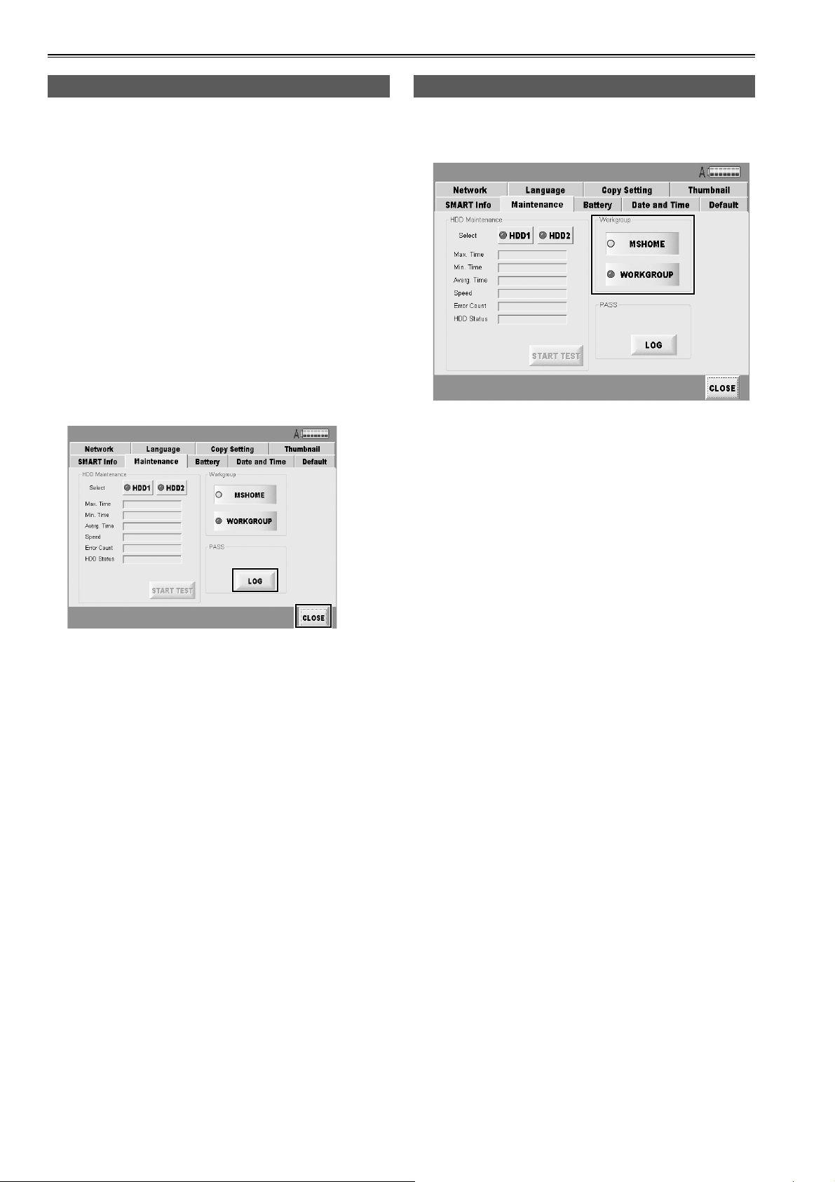
Maintenance (continued)
Creating PASS registration data
Register as a PASS (P2 Asset Support System)
member to use P2 Status Logger, an inspection utility
for P2 devices. With this utility, you can check the
software version of registered devices, update the
software, and manage usage records.
Prepare the latest data for checking and management
as follows.
1 Connect the unit to a network where there is
a computer with P2 Status Logger installed.
2 Press the LOG button at the bottom right of
the Maintenance tab screen on the SETTING
screen.
The latest registration data is created automatically.
Selecting a workgroup
You can choose either MSHOME or WORKGROUP as
the name of the workgroup to be used by the network.
2
3
On the computer mentioned in step 1, access the
registration folder on the unit (\P2Writer PASS) over
the network and acquire the registration data.
You can now review a variety of information about the
unit and manage records.
3 After registration data is acquired, press the
CLOSE button to return to the main screen.
44
Page 45

Version up
Follow the steps below to proceed with version
updating.
1 The version update module which is
downloaded from the Panasonic home page
contains compressed files so unzip them.
For further details about the updating methods,
refer to the following website.
https://eww.pavc.panasonic.co.jp/pro-av/
2 On the main screen, press the UPDATE
button.
The following message is displayed.
5 If a new version is found, the version will be
updated automatically. A message prompting
you to restart the unit is then displayed so
restart the unit.
If only the data for an old version is found, the
version is not updated.
6 After the unit has been restarted, check that
the version has been updated successfully
by noting the version number on the ABOUT
screen.
3 At the time when step 2 is taken, copy
the data which was unzipped in step 1
into the unit's version update folder (C:\
P2WriterUpdate) over the network from the
PC used to download the data.
4 After copying the data, please push the OK
button.
Press OK button to go back to the main screen.
The number of the version is indicated in "X.X.XX"
displayed in the dialog box.
45
Page 46

Connecting to a computer
Network connecting
When data sharing has been set using the SHARE
function, the HDD data which has been set to be
shared over the network can be accessed. For
security reasons, “Read Only” is displayed if access is
attempted by external users.
When you connect this unit to another computer via a
network, the computer must be set up to enable the
joint drives of the Windows computer to be accessed.
You have to refer to the joint part of the network of the
computer for details of the setting.
Inserting the HDD directly in the 5 inch bay unit
If identical 5-inch bay units have been installed, the
HDDs unmounted from the unit can be connected
directly.
It is also possible to connect discrete HDDs by using
the interfaces.
The contents may be deleted in the OS such as
Windows, Macintosh, Linux for the clips are in FAT32
format. Please understand it when you access to HDD.
Backing up the data
We recommend that you make a backup on a separate storage media in order to protect the important data saved
in the HDD.
It is necessary to check the volume of the storage media which used to back up the data.
For Windows
● Using Windows Explorer
Select top-level folders and files of a displays
drive on the unit. Copy the folder to your preferred
target folder on the computer. Execute the same
procedure on all drives of the unit.
● Using the “P2 Viewer”
Select needed clips and copy them to your preferred
target folder on the computer, where you have
set up the virtual drive. Refer to the P2 viewer’s
operating instructions for details on operation.
For Macintosh
● Using Finder
Double-click folders displayed on the desktop
(which represent drives on the unit) to open them.
Select top-level folders and files and copy them to
your preferred folder on the computer. Copy all the
contents of other drives on the unit the same way.
Troubleshooting
If the unit seems to be malfunctioning, try checking the following points.
If the problem persists, contact the place of purchase.
Symptom
The unit does not go on even when
the front POWER button is pressed.
The auto copying does not begin
after inserting P2 cards.
P2 cards cannot be formatted • Is the write-protect switch set to PROTECT?
• Is the rear POWER switch at the OFF setting?
• Is the battery drained?
• Is the external DC power supply connected correctly?
• Is the remaining volume of HDD enough?
• Is there enough charge left in the battery?
• Is the auto copy function set to OFF?
• Is the P2 card inserted correctly?
What to check
46
Page 47

Specifications
Power supply
Power consumption
indicates safety information.
External IF
LAN1/LAN2 : Gigabit Ethernet LAN port
Dimensions (W) × (H) × (D)
368 mm × 177 mm × 303 mm
(14.49 inches × 6.97 inches × 11.93 inches)
(Excluding protrusions)
Weight
Approx. 6.3 kg (13.86 lb)
(excluding the HDDs and 5-inch bay units)
Operation environment
Operating temperature: 0 °C to 40 °C
(32 °F to 104 °F)
Humidity: 10 % to 85 %
Storage temperature: -20 °C to 60 °C
(-4 °F to 140 °F)
Humidity: 10 % to 85 %
DC 12 V (11 V to 17 V)
70 W
In order to protect the HDD, if the internal
temperature of the HDD exceeds the specified
temperature range of the unit, a warning is
displayed and some operations are disabled,
because operation under these conditions may
damage the unit.
Requirement for connecting to PC
Be able to connect to Microsoft Network
Be able to connect the PC using a Gigabit LAN.
Specifications of HDD which can be used
(Optional)
SATA-2, 7200 r/min, 3.5-inch internal type
5-inch bay unit box (×2) specifications
Power : Power source connector for SATA
4 pin power connector
SATA signal : 7 pin connector for SATA
Audio output connectors
Headphone output: 3.5-mm stereo mini jack ×1
Speakers×1
47
Page 48

Information for Users on Collection and Disposal of Old Equipment
and used Batteries
These symbols on the products, packaging, and/or accompanying documents mean that used electrical and electronic
products and batteries should not be mixed with general household waste.
For proper treatment, recovery and recycling of old products and used batteries, please take them to applicable collection
points, in accordance with your national legislation and the Directives 2002/96/EC and 2006/66/EC.
By disposing of these products and batteries correctly, you will help to save valuable resources and prevent any potential
negative effects on human health and the environment which could otherwise arise from inappropriate waste handling.
For more information about collection and recycling of old products and batteries, please contact your local municipality,
your waste disposal service or the point of sale where you purchased the items.
Penalties may be applicable for incorrect disposal of this waste, in accordance with national legislation.
For business users in the European Union
If you wish to discard electrical and electronic equipment, please contact your dealer or supplier for further information.
Information on Disposal in other Countries outside the European Union
These symbols are only valid in the European Union. If you wish to discard these items, please contact your local
authorities or dealer and ask for the correct method of disposal.
Note for the battery symbol (bottom two symbol examples):
This symbol might be used in combination with a chemical symbol. In this case it complies with the requirement set by the
Cd
Directive for the chemical involved.
 Loading...