

Page 1
AG-HPG20P
AG-HPG20E
AG-HPG20
■
This product is eligible for the P2HD
5 Year Warranty Repair Program. For
details, see page 6.
IntroductionFor your
Operating Instructions
Memory Card Portable Recorder
Model No.
Model No.
parts
Name of the
Preparations
FRANÇAIS
ESPAÑOL
Before operating this product, please read the instructions carefully and save
this manual for future use.
F0109T0 -M
Printed in Japan
Pour des explications en français, veuillez vous reporter au CD-ROM fourni.
Para la explicación en español, consulte el CD-ROM uministrado.
D
ENGLISH
VQT1X51
Displays Editing Saving data Recording Playback
Menu
reference
Page 2
Read this first!
CAUTION
RISK OF ELECTRIC SHOCK
DO NOT OPEN
CAUTION: TO REDUCE THE RISK OF ELECTRIC
SHOCK, DO NOT REMOVE COVER (OR BACK).
NO USER-SERVICEABLE PARTS INSIDE.
REFER TO SERVICING TO QUALIFIED SERVICE
WARNING:
TO REDUCE THE RISK OF FIRE OR
•
SHOCK HAZARD, DO NOT EXPOSE THIS
EQUIPMENT TO RAIN OR MOISTURE.
TO REDUCE THE RISK OF FIRE
•
OR SHOCK HAZARD, KEEP THIS
EQUIPMENT AWAY FROM ALL LIQUIDS.
USE AND STORE ONLY IN LOCATIONS
WHICH ARE NOT EXPOSED TO THE
RISK OF DRIPPING OR SPLASHING
LIQUIDS, AND DO NOT PLACE ANY
LIQUID CONTAINERS ON TOP OF THE
EQUIPMENT.
PERSONNEL.
The lightning flash with arrowhead symbol,
within an equilateral triangle, is intended to
alert the user to the presence of uninsulated
“dangerous voltage” within the product’s
enclosure that may be of sufficient magnitude
to constitute a risk of electric shock to
persons.
The exclamation point within an equilateral
triangle is intended to alert the user to
the presence of important operating and
maintenance (servicing) instructions in the
literature accompanying the appliance.
indicates safety information.
CAUTION:
THE MAINS PLUG OF THE POWER
SUPPLY CORD SHALL REMAIN READILY
OPERABLE.
THE AC RECEPTACLE (MAINS SOCKET
OUTLET) SHALL BE INSTALLED NEAR
THE EQUIPMENT AND SHALL BE EASILY
ACCESSIBLE.
TO COMPLETELY DISCONNECT THIS
EQUIPMENT FROM THE AC MAINS,
DISCONNECT THE POWER CORD PLUG
FROM THE AC RECEPTACLE.
CAUTION:
Danger of explosion or fire if battery is
mistreated.
For Battery Pack
Replace only with same or specified type.
•
Do not disassemble or dispose of in fire.
•
Do not store in temperatures over 60°C
•
(140°F).
Use specified charger.
•
Do not leave the battery in an automobile
•
exposed to direct sunlight for a long period
of time with doors and windows closed.
Memory Card Portable Recorder
The rating plate is on the underside of the unit.
AC Adapter
The rating plate is on the underside of the AC
Adapter.
Disconnect the AC mains plug from the AC
mains socket when not in use.
WARNING:
Always keep memory cards out of the reach of
babies and small children.
CAUTION:
TO REDUCE THE RISK OF FIRE OR SHOCK
HAZARD AND ANNOYING INTERFERENCE,
USE THE RECOMMENDED ACCESSORIES
ONLY.
CAUTION:
Excessive sound pressure from earphones
and headphones can cause hearing loss.
2
CAUTION:
In order to maintain adequate ventilation, do
not install or place this unit in a bookcase,
built-in cabinet or any other confined space.
To prevent risk of electric shock or fire hazard
due to overheating, ensure that curtains
and any other materials do not obstruct the
ventilation.
Page 3
indicates safety information.
FCC NOTICE (USA)
Declaration of Conformity
Model Number: AG-HPG20P
Trade Name: Panasonic
Responsible Party: Panasonic Corporation of North America One Panasonic Way, Secaucus, NJ
Support contact: Panasonic Broadcast & Television Systems Company 1-800-524-1448
This device complies with Part 15 of FCC Rules.
Operation is subject to the following two conditions:
(1) This device may not cause harmful interference, and (2) this device must accept any
interference received, including interference that may cause undesired operation.
To assure continued compliance, follow the attached installation instructions and do not make any
unauthorized modifications.
07094
CAUTION:
This equipment has been tested and found to comply with the limits for a Class B digital device,
pursuant to Part 15 of the FCC Rules. These limits are designed to provide reasonable protection
against harmful interference in a residential installation. This equipment generates, uses and can
radiate radio frequency energy and, if not installed and used in accordance with the instructions,
may cause harmful interference to radio communications. However, there is no guarantee
that interference will not occur in a particular installation. If this equipment does cause harmful
interference to radio or television reception, which can be determined by turning the equipment off
and on, the user is encouraged to try to correct the interference by one of the following measures:
Reorient or relocate the receiving antenna.
•
Increase the separation between the equipment and receiver.
•
Connect the equipment into an outlet on a circuit different from that to which the receiver is
•
connected.
Consult the dealer or an experienced radio/TV technician for help.
•
The user may find the booklet “Something About Interference”
available from FCC local regional offices helpful.
FCC Warning:
To assure continued FCC emission limit compliance, follow the attached installation instructions and
the user must use only shielded interface cables when connecting to host computer or peripheral
devices. Also any unauthorized changes or modifications to this equipment could void the user's
authority to operate this device.
NOTIFICATION (Canada)
This class B digital apparatus complies with Canadian ICES-003.
Operating precaution
Operation near any appliance which generates strong magnetic fields may give rise to noise in the video
and audio signals. If this should be the case, deal with the situation by, for instance, moving the source
of the magnetic fields away from the unit before operation.
IMPORTANT
“Unauthorized recording of copyrighted television programs, video tapes and other materials may infringe the
right of copyright owners and be contrary to copyright laws.”
3
Page 4
Read this first! (continued)
For U.K.
indicates safety information.
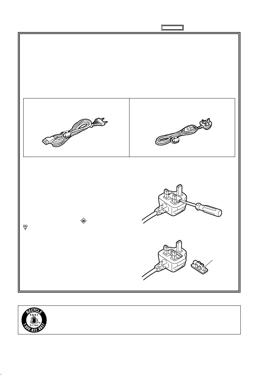
Caution for AC Mains Lead
FOR YOUR SAFETY PLEASE READ THE FOLLOWING TEXT CAREFULLY.
This product is equipped with 2 types of AC mains cable. One is for continental Europe, etc.
and the other one is only for U.K.
Appropriate mains cable must be used in each local area, since the other type of mains cable is
not suitable.
FOR CONTINENTAL EUROPE, ETC.
Not to be used in the U.K.
FOR U.K. ONLY
This appliance is supplied with a moulded
three pin mains plug for your safety and
convenience.
A 5 amp fuse is fitted in this plug.
Should the fuse need to be replaced please
ensure that the replacement fuse has a rating
of 5 amps and that it is approved by ASTA or
BSI to BS1362.
Check for the ASTA mark or the BSI mark
on the body of the fuse.
If the plug contains a removable fuse cover
you must ensure that it is refitted when the
fuse is replaced.
If you lose the fuse cover the plug must
not be used until a replacement cover is
obtained.
A replacement fuse cover can be purchased
from your local Panasonic Dealer.
FOR U.K. ONLY
How to replace the fuse
1. Open the fuse compartment with a
screwdriver.
2. Replace the fuse
Fuse
For USA and Canada
4
A lithium ion/polymer battery that is recyclable powers the product you have purchased.
Please call 1-800-8-BATTERY for information on how to recycle this battery.
Page 5

IMPORTANT SAFETY INSTRUCTIONS
1) Read these instructions.
2) Keep these instructions.
3) Heed all warnings.
4) Follow all instructions.
5) Do not use this apparatus near water.
6) Clean only with dry cloth.
7) Do not block any ventilation openings. Install in accordance with the manufacturer’s instructions.
8) Do not install near any heat sources such as radiators, heat registers, stoves, or other apparatus
(including amplifiers) that produce heat.
9) Do not defeat the safety purpose of the polarized or grounding-type plug. A polarized plug has two
blades with one wider than the other. A grounding-type plug has two blades and a third grounding
prong. The wide blade or the third prong are provided for your safety. If the provided plug does not fit
into your outlet, consult an electrician for replacement of the obsolete outlet.
10) Protect the power cord from being walked on or pinched particularly at plugs, convenience
receptacles, and the point where they exit from the apparatus.
11) Only use attachments/accessories specified by the manufacturer.
12) Use only with the cart, stand, tripod, bracket, or table specified by the manufacturer, or
sold with the apparatus. When a cart is used, use caution when moving the cart/
apparatus combination to avoid injury from tip-over.
13) Unplug this apparatus during lightning storms or when unused for long periods of time.
14) Refer all servicing to qualified service personnel. Servicing is required when the
apparatus has been damaged in any way, such as power-supply cord or plug is
damaged, liquid has been spilled or objects have fallen into the apparatus, the apparatus has been
exposed to rain or moisture, does not operate normally, or has been dropped.
IMPORTANT SAFETY INSTRUCTIONS
Recommendation for Use of Genuine Panasonic Battery (Rechargeable Battery)
Thank you for using a Panasonic product.
It has been found that counterfeit battery packs which look very similar to the genuine product are
made available to purchase in some markets. Some of these battery packs are not adequately
protected with internal protection to meet the requirements of appropriate safety standards. There is
a possibility that these battery packs may lead to fire or explosion. Please be advised that we are not
liable for any accident or failure occurring as a result of use of a counterfeit battery pack. To ensure that
safe products are used we would recommend that a genuine Panasonic battery pack is used.
Be aware that many batteries sold at extremely cheap prices or in situations where it is difficult to
•
verify the actual products before purchase have proven to be counterfeit.
5
Page 6
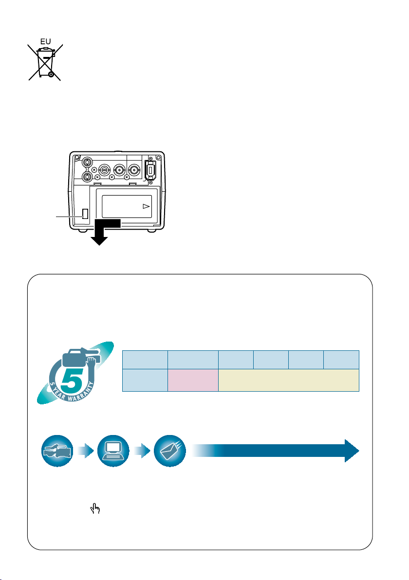
To remove the battery
PUSH
OUTPUT INPUT
CH 1
CH 2
AUDIO
VIDEO
HD/SD-SDI HD/SD-SDI
DVCPRO/DV
*1: Please note that this extended warranty is not available in some countries/regions.
*2: Not all models eligible for extended warranty coverage.
*3: The basic warranty period may vary depending on the country/region.
*4: Not all repair work is covered by this extended warranty.
*5: The maximum warranty period may be adjusted depending on the number of hours
the device has been used.
1st year
2nd year 3rd year 4th year
5th year
*
5
P2HD
device
*
2
Basic
warranty
*
3
Extended warranty repair
*
4
Purchase
P2 product
Register online
within 1 month
“Registration Notice”
e-mail sent
Details about user registration and the extended warranty:
http://panasonic.biz/sav/pass_e/
Free 5 years of Warranty Repairs
Customers who register as users on the website will receive
an extended warranty repair valid for up to five years.
P2HD 5 Year Warranty Repair Program*
1
Thank you for purchasing this Panasonic P2HD device.
Register as a user for this device to receive a special service warranty up to five
years of free warranty repairs.
Make sure to save the “Registration Notice”
e-mail during the warranty period.
Please note, this is a site that is not maintained by Panasonic Canada Inc. The Panasonic Canada Inc. privacy
policy does not apply and is not applicable in relation to any information submitted. This link is provided to
you for convenience.
Main Power Battery
Remove the battery while pressing the battery
eject button.
Battery
eject
button
Back-up Battery (Lithium Battery)
For the removal of the battery for disposal at the
end of its service life, please consult your dealer.
6
Page 7

EMC NOTICE FOR THE PURCHASER/USER OF THE APPARATUS
1. Applicable standards and operating environment for AG-HPG20E
The apparatus is compliant with:
• standards EN55103-1 and EN55103-2 1996.and
• electromagnetic environments E1, E2, E3, E4 and E5.
2. Pre-requisite conditions to achieving compliance with the above standards
<1> Peripheral equipment to be connected to the apparatus and special connecting cables
• The purchaser/user is urged to use only equipment which has been recommended by us
as peripheral equipment to be connected to the apparatus.
• The purchaser/user is urged to use only the connecting cables described below.
<2>
For the connecting cables, use shielded cables which suit the intended purpose of the apparatus.
• Video signal connecting cables
Use double shielded coaxial cables, which are designed for 75-ohm type high-frequency
applications, for SDI (Serial Digital Interface).
Coaxial cables, which are designed for 75-ohm type high-frequency applications, are
recommended for analog video signals.
• Audio signal connecting cables
If your apparatus supports AES/EBU serial digital audio signals, use cables designed for
AES/EBU.
Use shielded cables, which provide quality performance for high-frequency transmission
applications, for analog audio signals.
• Other connecting cables (IEEE1394, USB)
Use shielded cables, which provide quality performance for high-frequency applications, as
connecting cables.
• If your apparatus is supplied with ferrite core(s), they must be attached on cable(s)
following instructions in this manual.
3. Performance level
The performance level of the apparatus is equivalent to or better than the performance level
required by these standards.
However, the apparatus may be adversely affected by interference if it is being used in an EMC
environment, such as an area where strong electromagnetic fields are generated (by the presence
of signal transmission towers, cellular phones, etc.). In order to minimize the adverse effects of the
interference on the apparatus in cases like this, it is recommended that the following steps be
taken with the apparatus being affected and with its operating environment:
1. Place the apparatus at a distance from the source of the interference.
2. Change the direction of the apparatus.
3. Change the connection method used for the apparatus.
4. Connect the apparatus to another power outlet where the power is not shared by any
other appliances.
7
Page 8

Operating precautions
When using the unit in rainy or snowy weather,
at the beach or other locations, take care to
protect it from precipitation and sea water.
Otherwise, trouble may occur in the unit and
•
its cards. (It may not be possible to restore the
original functions)
Keep the unit away from appliances (such
as TV sets and TV game machines) which
generate magnetic fields.
When the unit is used on top of or near a TV set,
•
the images and sound may be distorted by the
electromagnetic waves emanating from the TV
set.
Strong magnetic fields generated by speakers
•
or large motors may damage the recordings or
distort the images.
The electromagnetic waves emanating from
•
microprocessors may adversely affect the unit
and distort the images and sound.
If the unit is adversely affected by an appliance
•
that generates magnetic fields and fails to
operate properly as a result, turn off its power,
and either remove its battery or unplug the AC
adapter from the power outlet. Then install the
battery again or re-connect the AC adapter. After
doing this, turn the unit’s power back on.
Do not use the unit near a radio transmitter or
high-voltage appliance.
Doing so may adversely affect the recorded
•
images and sound.
AC adapter and battery
When the battery temperature is extremely high
•
or extremely low or when the battery has not
been used for a prolonged period and been left
discharged, the [CHARGE] lamp will blink several
times, and charging will start automatically.
If the [CHARGE] lamp continues blinking even
•
when the battery temperature is normal, this may
be a sign of trouble in the battery or AC adapter.
Consult with your dealer.
When the battery is warm, it will take longer than
•
usual to recharge it.
When the AC adapter is used near a radio, the
•
sound from the radio may be distorted. Use the
AC adapter and radio at a distance of at least 1
meter from each other.
Noise is output while the AC adapter is being
•
used, but this is not a sign of trouble.
When carrying the unit around, take care not
to drop it.
Strong impacts may damage the unit’s body,
•
preventing it from operating properly.
Do not expose the unit to insecticides or
volatile sprays or liquids.
These substances may deform the unit’s body or
•
cause its paint to peel off.
Do not bring the unit into contact with products
•
made of rubber or vinyl for prolonged periods of
time.
When using the unit at the beach or similar
locations, take care to protect it from sand and
dust.
Sand and dust may damage the unit and its
•
cards. (Take particular care when inserting or
ejecting the cards)
8
Page 9

Characteristics of the battery
A rechargeable lithium-ion battery is used in this
unit. Electrical energy is generated by the chemical
reactions taking place inside it. These reactions
are susceptible to the effects of the ambient
temperature and humidity, and the higher or the
lower the temperature, the quicker the battery
charge will be used up. When the battery is used
where the temperature is extremely low, it may last
only 5 minutes or so even if the battery has been
fully charged.
When the battery reaches an extremely high
temperature, its protection function is activated,
making it impossible for the battery to be used for
a while.
After using the unit, always remember to
remove the battery.
Be sure to remove the battery from the unit. (If it
is left in place, a very faint current will continue to
flow even when the unit’s power has been turned
off) If the battery is left in place for a prolonged
period, it may discharge excessively so that it
cannot be used again even when it is charged at a
later time.
Protect the battery terminals.
Keep the battery terminals free from dust and
foreign matter.
If the battery has been inadvertently dropped,
check whether its body and terminal area have
been deformed.
Installing a deformed battery in the unit or in the
AC adapter may damage the unit or AC adapter.
Precautions when P2 cards and SD cards are to
be destroyed or given to other parties
The formatting and deletion functions provided by
the unit and personal computers serve merely to
change the file management information: they will
not completely erase all the data on the card.
When a card is to be destroyed or given to
another party, it is recommended that you destroy
the actual card physically or use a data deletion
software program for use with personal computers
available on the market to completely erase all the
data on the card.
You, the user, are responsible for managing the
data on your cards.
Liquid crystal display
When the same image or characters are left
•
displayed on the LCD monitor for a prolonged
period, they may become burned into the screen.
However, the original condition of the screen will
be restored after the power has been kept off for
several hours.
The liquid crystal part of the monitor has been
•
fabricated using high-precision technology. The
number of its effective pixels is more than 99.99
%, but this still leaves less than 0.01 % of its
pixels which may be missing or permanently
lighted. This is not a sign of trouble and will have
absolutely no effect on the images which have
been recorded.
The surface of the liquid crystal display may be
•
marked or scratched if it is wiped or rubbed firmly
with a rough cloth.
The response speed and brightness of the liquid
•
crystal change depending on the temperature at
which the display is used.
Condensation may form on the liquid crystal part
•
of the monitor if the unit is placed in a location
where there is a significant difference in the
temperature levels. If this happens, wipe off the
condensation with a soft dry cloth.
If the unit becomes very cold, the LCD monitor
•
screen will be darker than usual immediately
after the power has been turned on. When the
temperature inside the unit rises, the normal
brightness will be restored.
Connector protection
Attach the connector covers when the connectors
are not in use.
9
Page 10

Contents
Read this first! ................................................2
IMPORTANT SAFETY INSTRUCTIONS .........5
Recommendation for Use of Genuine
Panasonic Battery
(Rechargeable Battery) .......................... 5
Operating precautions ...................................8
How to use the unit ......................................12
Introduction
About this manual ........................................15
Before use ..................................................... 15
Accessories ..................................................17
Name of the parts
Name of the parts .........................................18
Operation area ................................................ 18
Mechanism area and input/output connector
area ............................................................. 19
Preparations
Charging the battery ....................................20
Charging .......................................................... 20
Installing and removing the power
supply ....................................................21
Installing and removing the battery ................. 21
Connecting and disconnecting
the power cable ...........................................21
Basic operations........................................... 22
Turning the power on and off ........................... 22
Using the LCD monitor .................................... 22
Menu operations .............................................. 23
Operation modes ............................................. 24
LCD monitor settings ....................................... 26
Setting date and time ...................................... 27
P2 cards......................................................... 28
Inserting P2 cards ........................................... 28
P2 card access LED and P2 card status ......... 28
Formatting P2 cards ........................................ 29
P2 card protection ...........................................29
Ejecting P2 cards ............................................ 30
P2 card recording durations ............................31
Dividing clips over 4 GB in size ....................... 31
LOOP REC recording ...................................... 32
Other .............................................................. 32
USER button ................................................... 32
Charging the internal battery ........................... 32
Using SD/SDHC memory cards ................... 33
Inserting and removing the SD card ................ 33
Formatting SD cards ....................................... 33
Precaution for using SD cards ......................... 33
Saving USER files on SD cards................... 34
10
Playback
Thumbnail display ........................................ 35
Playback formats ............................................. 35
Names and functions of thumbnail display
screen parts ................................................. 35
Changing the displays on the thumbnail
display screen ............................................. 38
Setting the items to be displayed .................... 39
Clip management.......................................... 40
Selecting clips ................................................. 40
Deleting clips ................................................... 40
Repairing and connecting clips ....................... 41
Copying clips ................................................... 42
Displaying the clip information ......................... 43
Editing the clip information ..............................45
Adding meta-data to clips ................................ 46
Adding shot marks to clips .............................. 54
Displaying the P2 card status .......................... 54
Displaying SD card information ....................... 56
Clip playback ................................................57
Playing back clips ............................................ 57
Single clip playback ......................................... 58
Variable-speed playback ................................. 59
Clip and text memo forward/reverse ............... 59
Rapid forward/rapid reverse playback ............. 59
Frame feed playback ....................................... 59
Repeat playback .............................................. 59
Adding text memos .......................................... 60
Playback from text memo position .................. 60
Deleting text memos ........................................ 61
Dividing and copying clips using text memos
Replacing thumbnail images ...........................61
... 61
Outputting images to an external monitor
for playback .......................................... 62
Setting the outputs .......................................... 62
Adjusting the output volume level during
recording and playback ............................... 62
Adjusting the output volume level during
variable-speed playback .............................. 62
Recording
Recording data on P2 cards ........................ 63
Recording ........................................................ 63
2-slot continuous recording ............................64
Waveform monitor (WFM) displays ................. 64
Time code displays .......................................... 65
Setting the recording time code ....................... 65
Set the user’s bit .............................................. 66
Page 11

Saving data
Copying data from P2 cards to the
hard drive .............................................. 67
Switching to the USB HOST mode .................. 68
Usable hard drives .......................................... 68
Types of hard drives and usable functions ...... 69
Formatting the hard drive ................................70
Exporting data to a hard drive in 1-card
increments ................................................... 71
Exporting one clip at a time to a hard drive ..... 72
Hard drive data display .................................... 74
Deleting the partition ....................................... 75
Thumbnail displays of clips on the hard drive
Displaying the clip information on the
hard drive ....................................................76
... 76
Connecting the hard drive for use .............. 77
Importing data from a hard drive to P2 cards
Easy playback of clips on the hard drive
(For viewing materials) ................................78
Deleting clips on the hard drive ....................... 78
... 77
Editing
Editing by means of external devices ........79
Editing data content on the P2 card
(USB DEVICE mode) .................................. 79
Editing in the USB DEVICE mode ................... 79
Displays
Screen displays ............................................80
Normal displays ............................................... 80
Major warning displays .................................... 82
Selecting what is to be displayed
on the screen ............................................... 85
Recording/output supporting format ..........86
Menu
Basic operations on the setting menus .....88
Initializing the setting menu ............................. 88
Setting menu configuration ......................... 89
List of setting menus ...................................90
RECORDING SETUP screen .......................... 90
TIMECODE SETUP screen ............................. 93
SW MODE screen ........................................... 97
PLAYBACK FUNCTIONS screen .................... 98
AV OUT SETUP screen ................................... 99
DISPLAY SETUP screen ............................... 103
CARD FUNCTIONS screen .......................... 105
OTHER FUNCTIONS screen ........................ 106
DIAGNOSTIC screen ....................................107
OPTION MENU screen .................................108
For your reference
Warning system table ................................109
Troubleshooting (Q&A) .............................. 110
Software information for this product ...... 112
Updating the drivers installed
in the unit ............................................. 113
Maintenance ................................................ 113
Condensation .............................................. 113
Storage precautions ................................... 114
Handling the data recorded on
P2 cards ............................................... 115
Use of SD/SDHC memory cards ................ 116
Specifications ............................................. 117
11
Page 12
How to use the unit
AG-HPG20
AG-HPG20
AG-HPG20
Housed in a compact cabinet which can be battery-powered, this Memory Card Portable Recorder is
a compact recording/playback unit coming with two P2 card slots, a 3.5-inch LCD monitor, USB 2.0,
IEEE1394, composite signal, SDI and many other input/output signal connectors. It can be easily operated
to play back the data content which has been shot by a P2 camera recorder. It is also capable of backup
recording and file management, and it supports outdoor field recording.
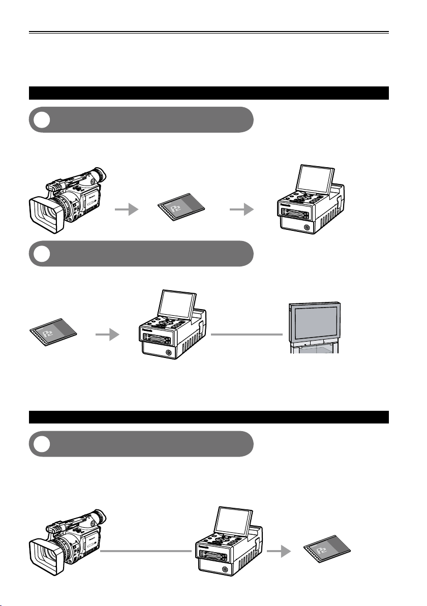
Playing back data content on the P2 card
Playing back the data on the unit’s LCD
1
monitor (Page 57)
Data content (both pictures and sound) which has been shot on P2 cards using a P2 camera recorder can
be played back on the spot.
P2 camera recorder
P2 card
Outputting the data to the external monitor
2
for playback (Page 62)
The data content (both pictures and sound) on P2 cards can be output to the external monitor, and played back.
AG-HPG20 (this unit)
P2 card
HD/SD-SDI output
AG-HPG20 (this unit)
External monitor
Video output/Audio
output
Use VIDEO/SDI/1394 output for monitoring purpose in other modes than playback mode. It is not
•
suitable for recording purpose because Pictures/Sound/Time cord (TC/UB) may become incorrect.
If the content on the P2 card has been recorded in DVCPRO HD, DVCPRO50, DVCPRO25 or DV
•
format, signals are also output from DVCPRO/DV input/output connector (IEEE1394).
(AVC-Intra100 and AVC-Intra50 do not support 1394 output)
Recording data on P2 cards
1394 connection (Page 63)
3
You can record data on P2 cards by connecting the unit to the external devices equipped with 1394
(DVCPRO/DV stream) output, such as a P2 camera recorder. The unit’s recording start and stop
operations can be performed from some camera recorders.
Recording in AVC-Intra100 and AVC-Intra50 modes is not possible with 1394 input.•
P2 camera recorder
1394 cable
AG-HPG20 (this unit)
P2 card
12
Page 13
AG-HPG20
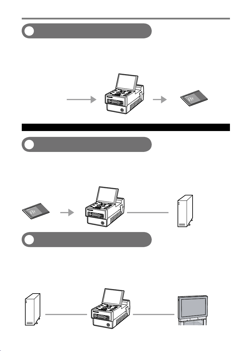
HD/SD-SDI connection (Page 63)
AG-HPG20
AG-HPG20
4
You can record data on P2 cards by connecting the unit to the external devices equipped with HD/SD-SDI
output. The unit’s recording start and stop operations can be performed from some camera recorders.
(When SDI input is selected)
(For supporting devices, refer to page 91)
AG-HPG20 (this unit)
P2 card
HD/SD-SDI signal
Using an external hard drive (HDD)
Saving data onto an external hard drive
5
(Page 67)
The data content on P2 cards can be saved onto an external HDD.
Also, the P2 content saved on an external HDD can be reloaded onto a P2 card.
(Only in the USB HOST mode)
1394 connection (File transfer) is not supported.•
AG-HPG20 (this unit)
Hard drive
P2 card
USB 2.0 cable
Checking the content saved onto an
6
external hard drive (Page 78)
The P2 content saved on an external HDD can be played back and checked. (Pulldown playback
(Playback with some images skipped))
(Only in the USB HOST mode)
1394 connection (File transfer) is not supported.
•
Both audio and images will not be output to the DVCPRO/DV input/output connector (IEEE1394).
•
Hard drive
USB 2.0 cable
AG-HPG20 (this unit)
External monitor
HD/SD-SDI output
Video output/Audio
output
13
Page 14
How to use the unit (continued)
AG-HPG20
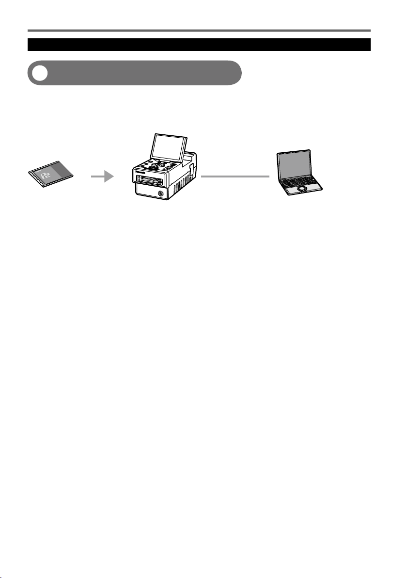
Using a PC
Editing by connecting the unit to a PC
7
(Page 79)
The unit can be USB-connected to a PC, and the PC can then be used to edit (i.e. exchanging data, etc.)
the data content on P2 cards. (USB DEVICE mode)
1394 connection (File transfer) is not supported.•
AG-HPG20 (this unit)
PC
P2 card
USB 2.0 cable
14
Page 15
IEEE1394
connector
IEEE1394
cable edge
IEEE1394
connector
(Wrong)
(Correct)
IEEE1394
cable edge
About this manual
Note concerning illustrations in these instructions
• Illustrations (portable recorder, menu screens, etc.) in these operating instructions differ slightly from the
actual portable recorder.
References
• References are shown as (Page 15).
Each explanation, company names and product names described in these operating instructions are
trademarks or registered trademarks of each company.
Before use
Be absolutely sure to check the date, time and time zone, and set them if necessary.
The calendar and time zone affect the management and playback sequence of the data content which
•
has been recorded. Before recording, set and check year/month/day, time and time zone. (Page 27)
No compensation can be made for video recordings.
The manufacturer will not provide any compensation in the event that images fail to be recorded due to
•
trouble while the unit and P2 card are being used.
Concerning copyrights
You may use the images and sound which you have recorded for your own personal enjoyment only;
•
under copyright laws, you may not use them for any other purpose without the permission of the
copyright holders.
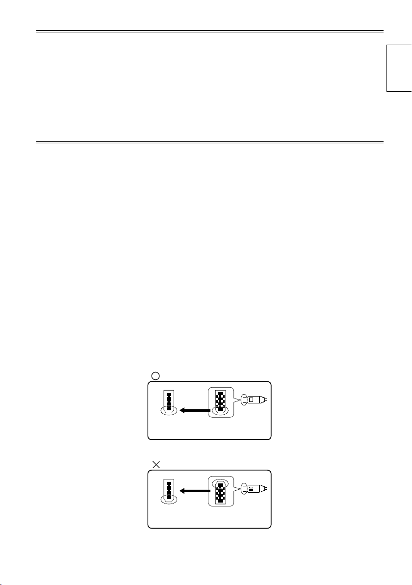
IEEE1394 cable connection
Be sure to observe the following when connecting the IEEE1394 cable (optional). (Improper connection
may cause malfunction in this unit and external devices)
Before connecting or disconnecting the IEEE1394 cable, you must turn off the power of all devices
•
connected to the unit.
Devices equipped with earth terminals must be used in the grounded condition (or in the connected
condition to the commonly-used GND).
When connecting the unit to a component which uses a 4-pin type of connector, be sure to connect this
•
unit’s connector (6-pin type) first.
IEEE1394 cable connector has a direction.
•
When connecting the unit to a component which uses a 6-pin type of IEEE1394 connector, be sure to
•
check the shape before connection as below
Introduction
During recording or playback in AVC-Intra100 and AVC-Intra50 modes, input/output from the DVCPRO/
•
DV input/output connector (IEEE1394) is not possible.
15
Page 16
Before use (continued)
Media which can be used with this unit
You may use the following media. For further details, refer to the pages on the media concerned.
P2 cards (Page 28)
•
SD/SDHC memory cards (Page 33)
•
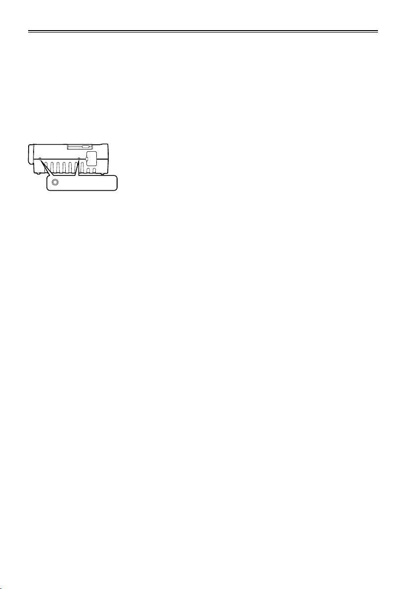
Screw holes
M5 (5 mm diameter) screws with a length of 10 mm can be used for the four screw holes on the side
panels of the unit.
When using the screws, do not tighten them too much. The unit may be damaged if screws other than 10
mm long M5 (5 mm diameter) screws are used.
Screw holes
Refer to page 8 for other operating precautions.
The other side panel also has two screw holes.
16
Page 17
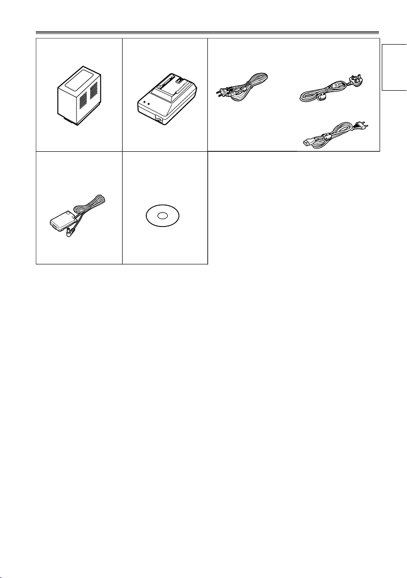
Accessories
*
Battery
DC cord
* For the model number of the battery, refer to the [ACCESSORIES] item. (Page 118)
AC adapter
CD-ROM
AC power supply cords
AG-HPG20P AG-HPG20E
( For the U.K.)
Introduction
( For areas other than
the U.K.)
17
Page 18
Name of the parts
EXIT/2
ALT/3
3
5
7
8
9
10
11
13
12
4
6
2
1
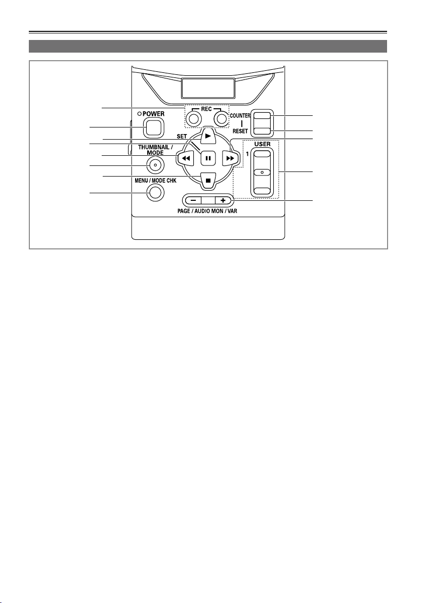
Operation area
1 REC button (Page 63)
2 POWER button (Pages 22, 110)
3 PLAY button (Pages 23, 58)
4 STILL/SET button (Pages 23, 58)
5 REW button (Pages 23, 58)
6 THUMBNAIL/MODE button
(Page 24)
7 STOP button (Pages 23, 58)
8 MENU/MODE CHK button
(Pages 23, 32)
9 COUNTER button (Page 65)
10 RESET button
(Pages 26, 34, 65, 66)
11 FF button (Pages 23, 58)
12 USER/EXIT/ALT button (Page 32)
13 PAGE/AUDIO MON/VAR button
(Pages 40, 59, 62)
• The button names are described such as
[THUMBNAIL/MODE] in this manual from now.
18
Page 19
Mechanism area and input/output connector area
EXIT/2
ALT/3
1
USER
SET
THUMBNAIL
/MODE
MENU/MODE CHK
REC
PAGE / AUDIO MON / VAR
POWER
COUNTER
RESET
AG-HPG20
PUSH
HOST
DEVICE
OUTPUT INPUT
CH 1
CH 2
AUDIO
VIDEO
DVCPRO/DV
HD/SD-SDI HD/SD-SDI
1
6
7
4
3
2
5
8
20
13
921
18
19
11
10
14 15 16 17
12
parts
Name of the
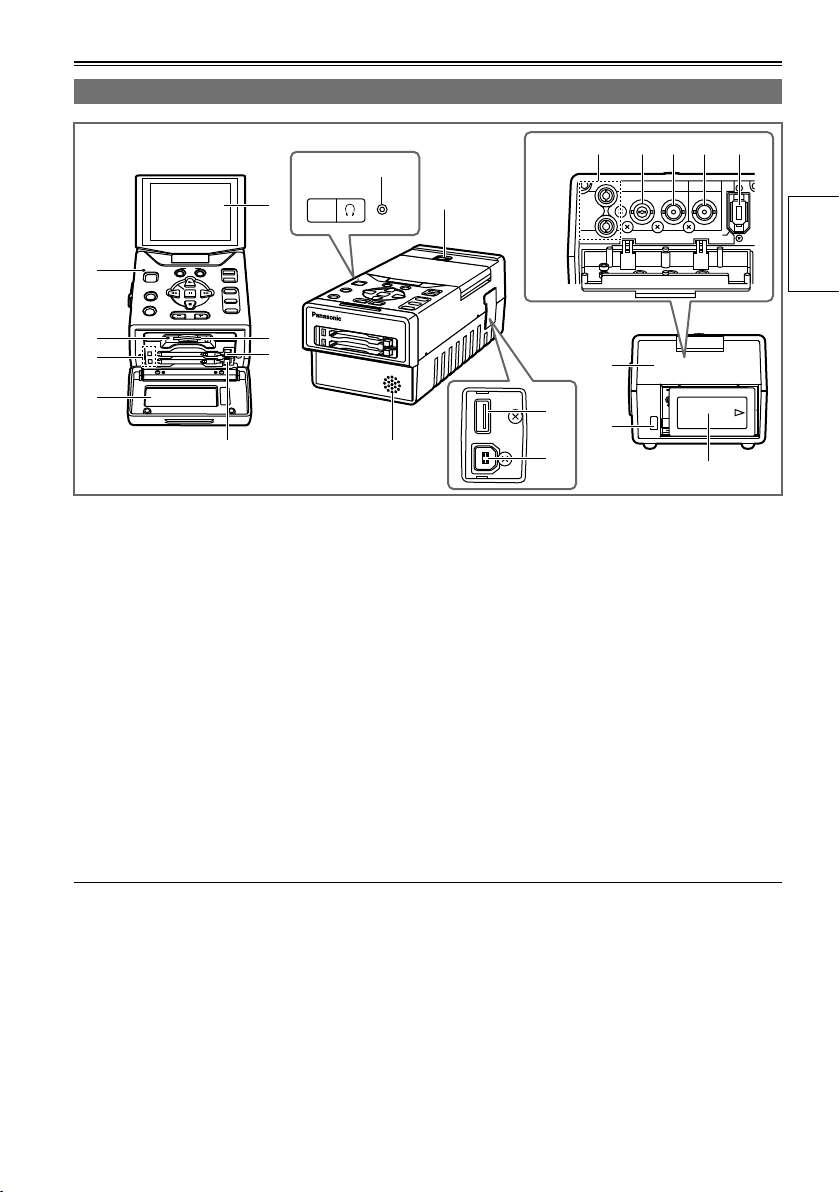
1 LCD monitor (Pages 22, 26)
2 Power display LED (Pages 22, 109)
3 SD card access LED (Page 33)
4 P2 card access LEDs (Page 28)
5 Card slot cover (Pages 28, 30)
6 SD card slot (Page 33)
7 P2 card slots (Page 28)
8 LCD monitor open button (Page 22)
9 Speaker (Pages 62, 82)
10 Connector area cover
11 Battery eject button (Page 21)
12 Battery (Page 20)
Use a cable equivalent level of 5C-FB with a double-layer shield to connect to HD/SD-SDI IN or HD/SD-
•
SDI OUT connector.
Use a cable with a double-layer shield to connect to DVCPRO/DV input/output connector (IEEE1394).
•
13 AUDIO OUT CH1/CH2 connectors
(Page 62)
14 VIDEO OUT connector (Page 62)
15 HD/SD-SDI OUT connector (Page 62)
16 HD/SD-SDI IN connector (Page 63)
17 DVCPRO/DV input/output connector
(IEEE1394) (Page 63)
18 USB HOST connector (USB2.0 Type A)
(Page 67)
19 USB DEVICE connector (USB2.0 Type B)
(Page 79)
20 Headphone jack (Pages 62, 82)
21 P2 card eject button (Page 30)
19
Page 20
Charging the battery
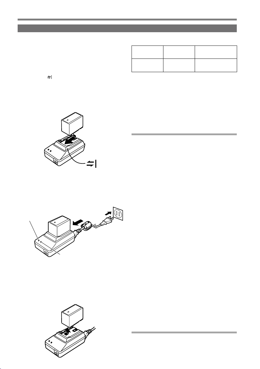
Charging
The battery has not been charged at the time of
purchase.
Before using the battery, give it a full charge using
the AC adapter. It is recommended that you have a
spare battery available in case you need it.
1 Place the battery horizontally while aligning
it with the mark on the AC adapter, and
slide it into position.
If the DC cord is connected to the AC adapter,
•
disconnect it before proceeding any further.
The battery cannot be charged if this cable is
left connected.
2 Connect the AC cable to the power outlet.
The POWER and CHARGE lamps on the AC
•
adapter light, and charging starts.
If the CHARGE lamp fails to light when the
•
battery has been installed, remove the battery
and then re-install it.
POWER
CHARGE
When the battery has been charged, the
•
CHARGE lamp on the AC adapter goes off.
Depending on the country and region, the
•
actual configuration of the power cord, plug,
and power outlet may differ from those shown
in these operating instructions.
3
Slide the battery out of position, and remove it.
Charging time and play time of supplied battery
Capacity Charging
time
5400 mAh Approx. 330
minutes
The times given in the above table are
•
approximate figures based on playback in the
AVC-Intra100 mode.
The times given in the above table are obtained
•
at an ambient operating temperature of 20 °C (68
°F) and an ambient relative humidity of 60 %. It
may take longer to charge the battery at other
temperature and humidity levels.
While the battery is being used or charged, it will
•
become hot.
If the playback and stop operations are repeated
•
more than necessary, the playback time will be
shorter than the time given in the above table.
When the battery is to be stored for a prolonged
period, it is recommended that you charge it once
a year, use the battery in the unit until its charge
is used up, and then return it to storage.
When the battery temperature becomes
•
extremely high or low or when a discharged
battery has been left unused for a prolonged
time, the CHARGE lamp will blink several times,
and charging will commence automatically.
When the CHARGE lamp continues to blink even
•
when the battery is at the right temperature,
it may indicate a failure in the battery or AC
adapter. Contact your dealer.
When the battery is warm, it will take longer than
•
usual to recharge it.
When the AC adapter is used near a radio, the
•
sound from the radio may be distorted. Use the
AC adapter and radio at a distance of at least 1
meter from each other.
Noise may be heard from the AC adapter while
•
the AC adapter is being used: this is normal and
not a sign of trouble.
The battery cannot be charged when power is
•
supplied to the unit from the AC adapter.
No guarantees are given for the operation of the
•
CGR-D16/CGR-D16s (1600 mAh) battery pack.
Continuous
playback time
Approx. 230
minutes
20
Page 21
Installing and removing the power supply
PUSH
OUTPUT INPUT
CH 1
CH 2
AUDIO
VIDEO
HD/SD-SDI HD/SD-SDI
DVCPRO/DV
PUSH
OUTPUT INPUT
CH 1
CH 2
AUDIO
VIDEO
HD/SD-SDI HD/SD-SDI
DVCPRO/DV
PUSH
OUTPUT INPUT
CH 1
CH 2
AUDIO
VIDEO
HD/SD-SDI HD/SD-SDI
DVCPRO/DV
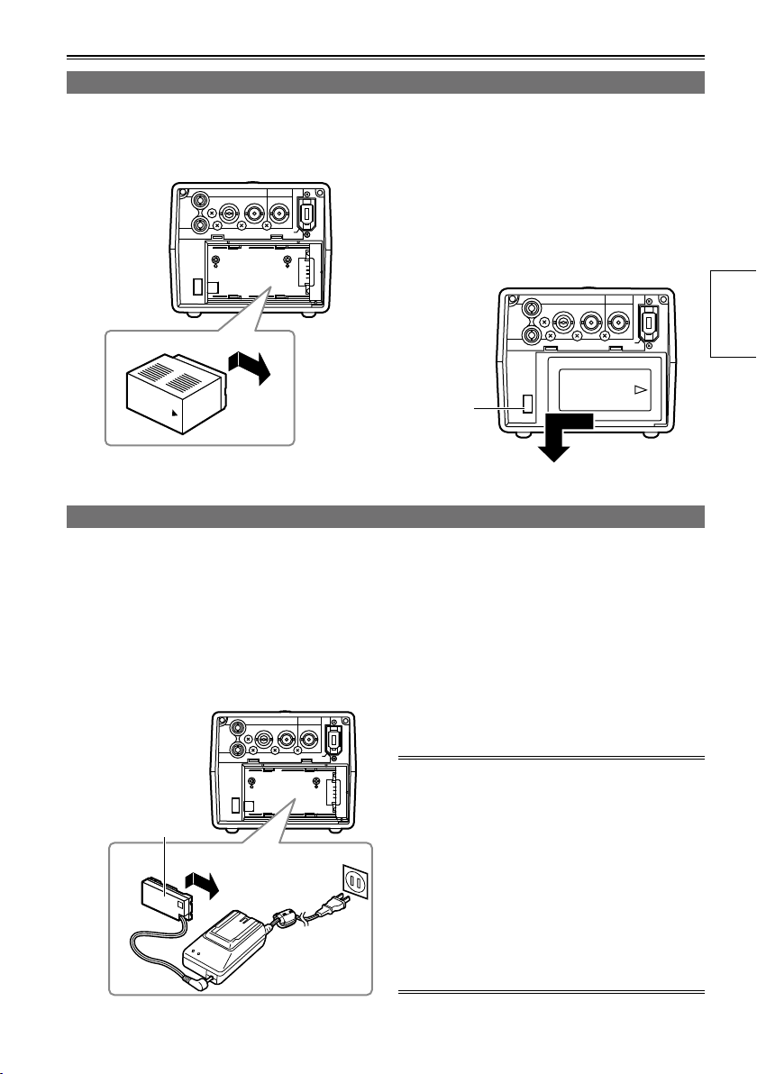
Installing and removing the battery
Insertion
1 Slide and insert the battery until it clicks
Removal
1 Press [POWER] for at least 2 seconds to
into place.
2 Remove the battery while pressing the
Connecting and disconnecting the power cable
Insertion
1 Connect the DC cord to the AC adapter.
Removal
1 Press [POWER] for at least 2 seconds to
2 Connect the AC power supply cord into the
power outlet.
2 Remove the DC cord’s battery connector
3 Slide and insert the DC cord plate until it
clicks into place.
3 Disconnect the AC power supply cord from
turn the power off, and check that the power
display LED has gone off. (Page 22)
battery eject button.
Support the battery with your hand to ensure
•
that it will not drop down.
Battery
eject
button
turn the power off, and check that the power
display LED has gone off. (Page 22)
while pressing the battery eject button.
the power outlet.
Preparations
DC cord’s
battery
connector
The battery cannot be charged when power is
•
supplied to the unit from the AC adapter.
The AC adapter is designed to work anywhere
•
in the world with supply voltages ranging from
100 V to 240 V and with power line frequencies
of 50 Hz and 60 Hz. However, in some countries
the shape of the power outlet receptacle differs.
In cases like this, obtain the plug that will fit the
receptacle. Obtain the conversion plugs after
consulting with your dealer.
When the unit is not being used, disconnect the
•
AC cable from the power outlet.
21
Page 22
Basic operations
AG-HPG20
AG-HPG20
AG-HPG20
AG-HPG20
EXIT/2
ALT/3
1
USER
SET
THUMBNAIL
/MODE
MENU/MODE CHK
REC
PAGE / AUDIO MON / VAR
POWER
COUNTER
RESET
Turning the power on and off
Hold down [POWER] for at least 1 second.
The power display LED lights, and the power is turned on.
•
When [POWER] has been held down for more than 2 seconds while the power is on, the power display
•
LED will go off, and the power will be turned off.
Using the LCD monitor
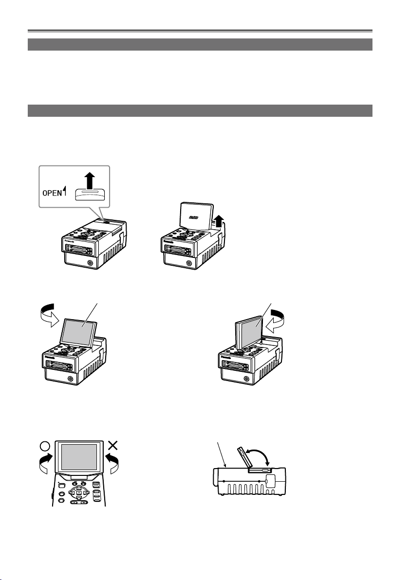
1 Hold down [POWER] for at least 1 second to turn the power on.
2 Raise the LCD monitor while pressing the LCD monitor open button in the direction shown by
the arrow.
3 Set the LCD screen to the angle where it is easiest to see its displays.
180º
Turn the LCD monitor
screen 180 degrees
counterclockwise so that
it is facing the front.
LCD monitor screen LCD monitor screen
The monitor cannot
•
be turned more than
180 degrees. Applying
excessive force beyond
this limit may cause
damage the unit.
Make sure that the LCD monitor is raised upright before turning it.
Once the LCD monitor
screen is positioned to
face the front, it cannot
be turned any further
in the counterclockwise
direction.
Applying excessive
•
force beyond this limit
may cause damage
the unit.
22
Function buttons
90º
In the clockwise
direction, the screen
can be turned up to 90
degrees.
The monitor cannot
•
be turned more than
90 degrees. Applying
excessive force beyond
this limit may cause
damage the unit.
120º
The LCD monitor screen
will not tilt more than
120 degrees toward the
function buttons.
Applying excessive
•
force beyond this limit
may cause damage
the unit.
Page 23
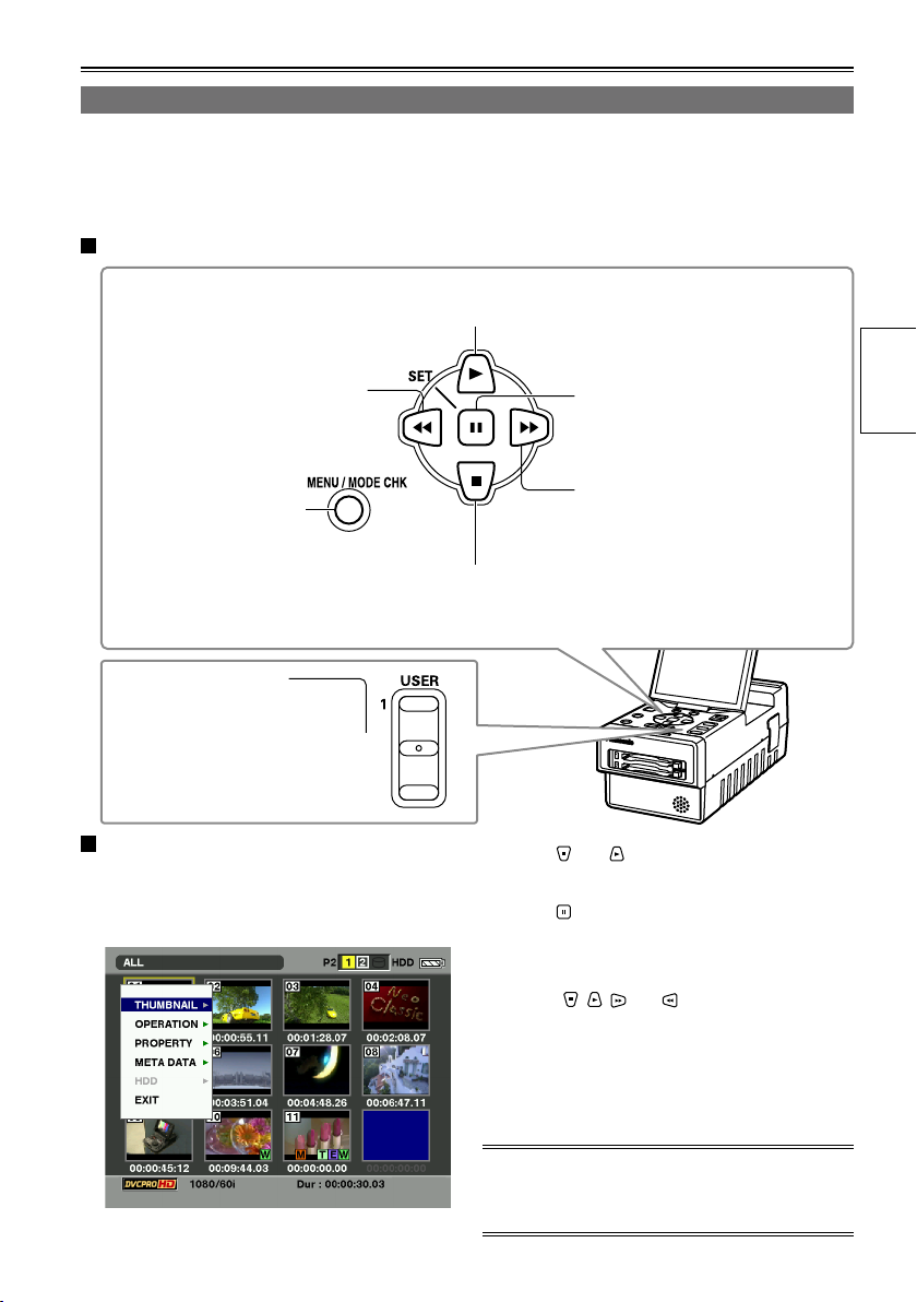
Menu operations
AG-HPG20
EXIT/2
ALT/3
This unit is provided with three kinds of screens: the thumbnail display screen, normal display screen
(SDI/1394 input recording standby mode, INT SG (Page 91), playback standby mode, etc.) and PC mode
screen (USB HOST mode, USB DEVICE mode). When [MENU/MODE CHK] is pressed on any of these
screens, the menu will be displayed. (No menus are displayed in the USB DEVICE mode)
Operations performed when the function buttons are pressed
This is used to move the menu highlighting to the item above;
depending on the menu item, it is used to change the value.
This is used to move the menu
highlighting to the item on the left;
depending on the menu item, it is
used to change the value.
This is used to display
the menus. When it is
pressed while a menu is
displayed, the menu is
exited.
When EXIT is assigned
to [EXIT/2], if you press
[EXIT/2] while a menu
is displayed, the menu
is exited.
Example of a menu operation: (when the
thumbnail display screen is displayed)
This is used to move the menu highlighting to
the item below; depending on the menu item, it
is used to change the value.
1 Press [MENU/MODE CHK] to display the
menu.
This is used to select items and
enter their values. When there is a
sub-menu, it is used to display the
sub-menu.
This is used to move the menu
highlighting to the item on the right;
depending on the menu item, it is
used to change the value.
2 Press and to move the menu
highlighting, and select the item.
3 Press .
If another menu has been displayed, repeat
•
steps 2 and 3.
Depending on the item, the value is changed
•
using , , and .
Depending on the item, a confirmation screen
•
will be displayed.
Depending on the item, the original screen is
•
restored automatically.
Preparations
4 Press [MENU/MODE CHK] to exit the menu.
For details on the menu operations on the normal
display screen, refer to “Basic operations on the
setting menus” on page 88.
23
Page 24
Basic operations (continued)
S
LOCK
QU
JUN 19 2009 23 : 59 : 59
60 : 24P
1
TC 12 : 34 : 56 : 00 106 min
1 2
1080i
C
H
2
C
H
3
C
H
4
C
H
P2
60
USB HOST
TEXT MEMO
REPEAT HDD
LACK
AVC-I100
CARD FUNCTIONS
SD CARD FORMAT
USER FILE
RETURN
CHANGE
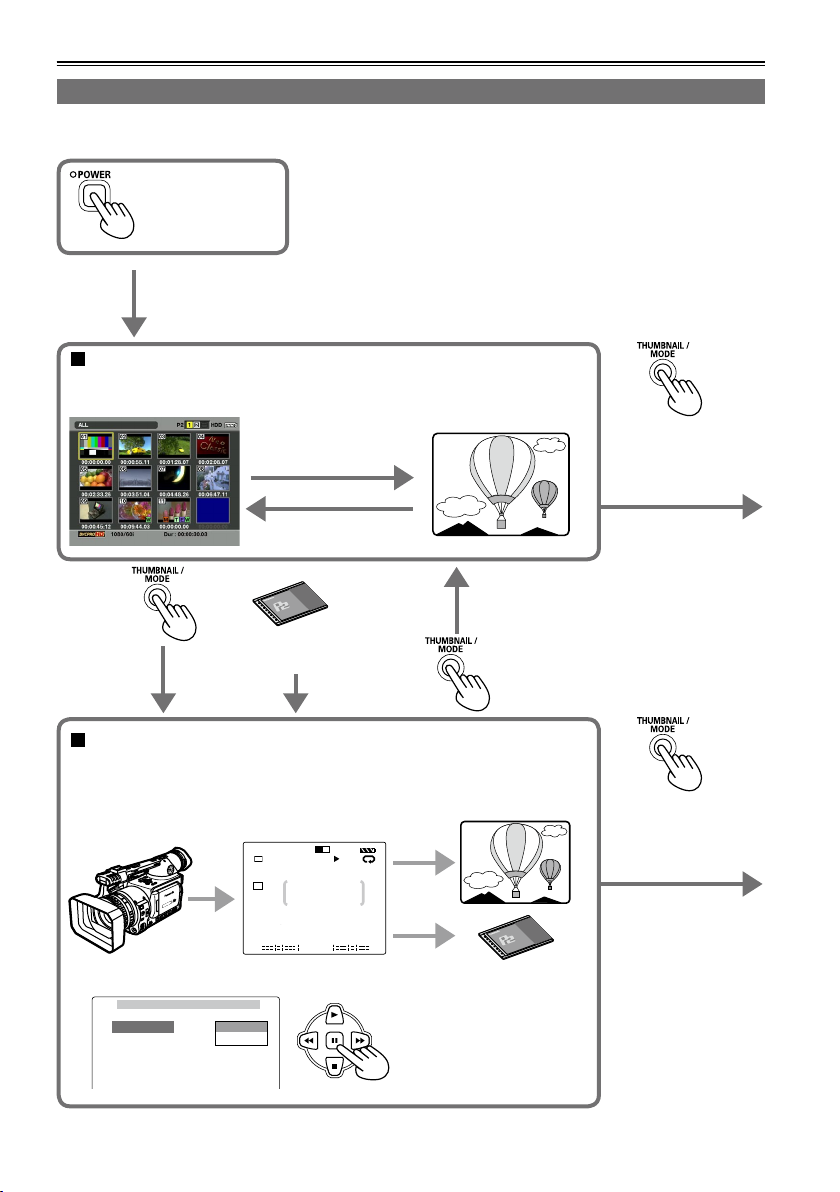
Operation modes
This unit has the following 3 modes which can be selected by pressing [THUMBNAIL/MODE].
Turn on the power.
Thumbnail display screen
On this screen, the data content on the P2 cards is displayed as
thumbnails to play back or manage the clips.
Playback
(PLAY, STILL, FF, REW)
Stop (STOP)
When a P2 card
has been ejected
Normal display screen
• Connect the unit to the devices equipped with the HD/SD-SDI input/
output or IEEE1394 connector, or set INT SG (Page 91) for playback and
recording.
Playback
Recording
• Display the menu, and perform the various settings.
Hold down this button
for at least 2 seconds
to switch to the PC
mode.
Hold down this button
for at least 2 seconds
to switch to the PC
mode.
24
Page 25
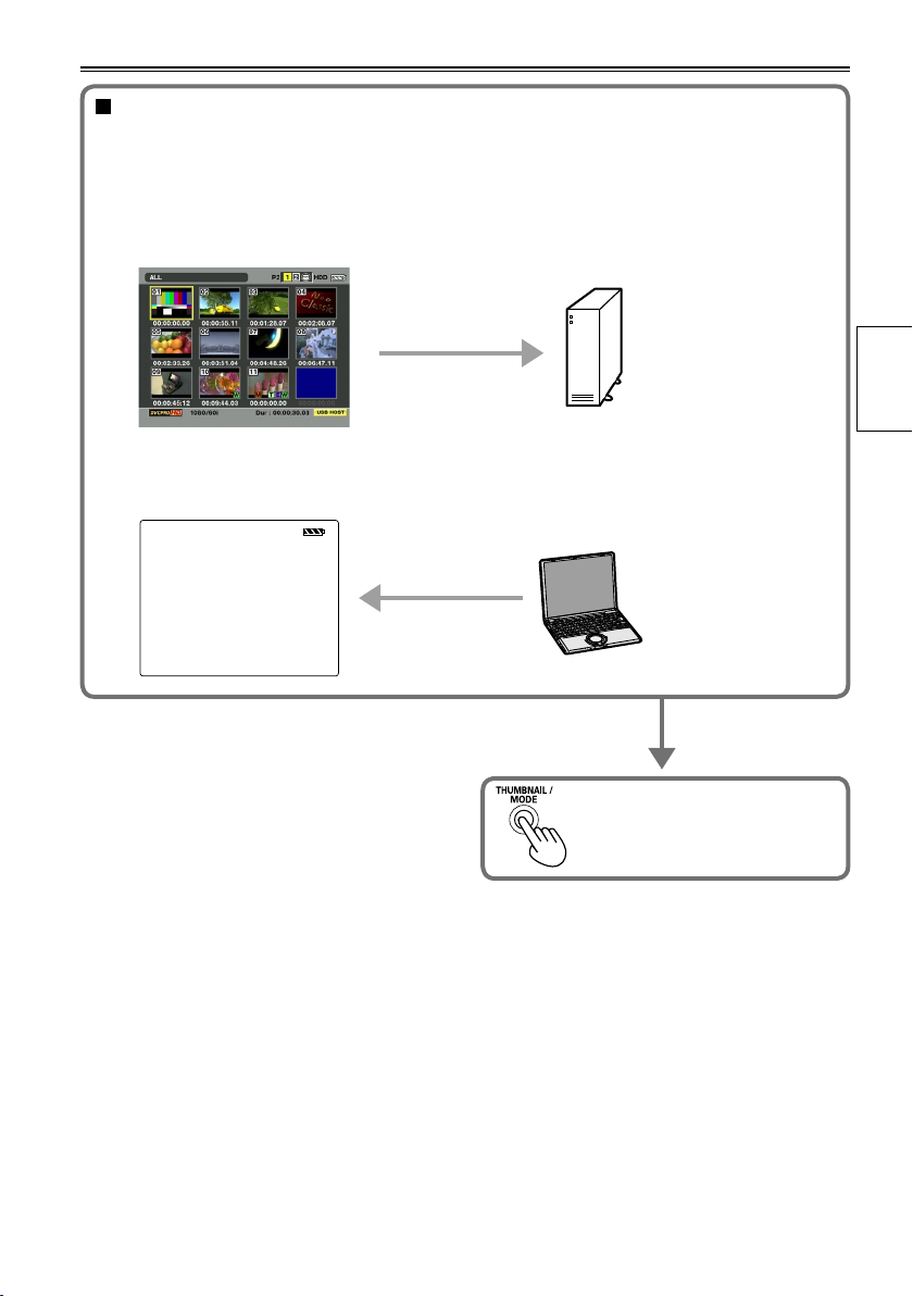
PC mode
Connect the unit to an external device, and save or manage the clips. Depending on the
connection method and purpose, the USB HOST mode and USB DEVICE mode are available;
perform the mode settings using the setting menu on the normal display screen.
• USB HOST mode
Connect to a device equipped with a USB connector, and operate the connected device.
• USB DEVICE mode
Connect to a device equipped with a USB connector, and operate the data on the unit’s P2 card
from the connected device.
USB DEVICE
Press and hold at least 2 seconds
to return to the thumbnail display
screen.
Preparations
25
Page 26
DISPLAY SETUP
PUSH MENU TO RETURN
OSD OUT SEL
DATE/TIME
P2CARD REMAIN
OTHER DISPLAY
LCD BACKLIGHT
LEVEL METER
CARD/BATT
LCD SETTING
OFF
CH1-4
ON
LCD
ON
TOTAL
CHANGE
RETURN
LCD SETTING
LCD CONTRAST
LCD BRIGHTNESS
LCD COLOR LEVEL
PUSH MENU TO RETURN
[ + ]
[ + ]
[ + ]
[ ]
_
[ ]
_
[ ]
_
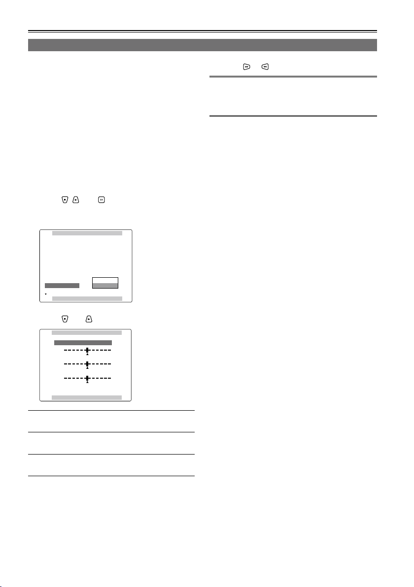
Basic operations (continued)
LCD monitor settings
1 Hold down [POWER] for at least 1 second to
turn the power on.
First check that an image is displayed on the
LCD monitor, and then adjust the angle of the
monitor to the position where it is easiest to see
its displays.
2 Press [THUMBNAIL/MODE] to display the
normal display screen.
3 Press [MENU/MODE CHK].
Basic operations on the setting menus (Page
•
88)
4 Using , , and , select “CHANGE” for
the “LCD SETTING” item on the setting
menu “DISPLAY SETUP” screen.
5 Using and , select the item to be set.
6 Using or , adjust the selected item.
When [RESET] is pressed, the adjusted values of
•
the selected items can be restored to their factory
settings.
7 Press [MENU/MODE CHK] 3 times to return
to the normal display screen.
LCD COLOR LEVEL:
LCD BRIGHTNESS:
LCD CONTRAST:
Note that if you set all LCD adjustment values to
•
This adjusts the color
density of the screen.
This adjusts the screen
brightness.
This adjusts the screen
contrast.
minimum, the menu screen will become difficult
to see.
26
Page 27
OTHER FUNCTIONS
PUSH MENU TO RETURN
PC MODE SELECT
BEEP SOUND
CLOCK SETTING
TIME ZONE
POWER SAVE
SYSTEM FREQ
USER FILE
USB HOST
OFF
>>>
0:00
OFF
59.94Hz
>>>
OTHER FUNCTIONS
PUSH MENU TO RETURN
PC MODE SELECT
BEEP SOUND
CLOCK SETTING
TIME ZONE
POWER SAVE
SYSTEM FREQ
USER FILE
USB HOST
OFF
RETURN
OFF
59.94Hz
>>>
CHANGE
CLOCK SETTING
PUSH MENU TO RETURN
YEAR
DAY
MONTH
HOUR
MINUTE
APR
07
24
13
2009
+/ /
/
-
SEL
: PUSH
: PUSH
CLOCK SETTING
PUSH MENU TO RETURN
YEAR
DAY
MONTH
HOUR
MINUTE
APR
07
24
13
2009
+/ /
/
-
SEL
: PUSH
: PUSH
CLOCK SETTING
PUSH MENU TO RETURN
YEAR
DAY
MONTH
HOUR
MINUTE
MAY
07
24
13
2009
+/ /
/
-
SEL
: PUSH
: PUSH
CLOCK SETTING
PUSH MENU TO RETURN
YEAR
DAY
MONTH
HOUR
MINUTE
MAY
20
25
17
2009
+/ /
/
-
SEL
: PUSH
: PUSH
Setting date and time
The “CLOCK SETTING” value is recorded on the data content (clips), and it affects the sequence in which
the thumbnails are played back. Before recording, be absolutely sure to check the “CLOCK SETTING” and
“TIME ZONE” settings, and set them if necessary. Described below is the procedure for setting date and
time to 5:20 PM on May 25, 2009.
1 Hold down [POWER] for at least 1 second to
turn the power on.
2 Press [THUMBNAIL/MODE] to display the
normal display screen.
3 Press [MENU/MODE CHK].
Basic operations on the setting menus (Page
•
88)
4 At the “TIME ZONE” item on the setting
menu “OTHER FUNCTIONS”, change the
time difference from Greenwich Mean Time
using and , and press . (Page 106)
5 Select “CHANGE” for the “CLOCK
SETTING” item on the setting menu
“OTHER FUNCTIONS” screen.
7 Press to move the setting item to
“MONTH”.
8 Press or to set “MONTH” to “MAY”.
9 Use the same method as in steps 7 and 8 to
set “DAY”, “HOUR” and “MINUTE”.
The 24-hour clock system is used by this unit.
•
Preparations
6 Press or to set “YEAR” to “2009”.
Any year from 2000 to 2037 can be set.
10 Press [MENU/MODE CHK] 3 times to
return to the normal display screen.
There may be a time error. Check if the
•
CLOCK shows the correct time before
shooting.
If the unit is going to be used overseas, do
•
not set the “CLOCK SETTING” to the current
time but input the time difference from GMT
using the “TIME ZONE”.
27
Page 28
P2 cards
Inserting P2 cards
When the unit is to be used for the first time, the first step is always to set the internal clock. (Page 27)
1 Hold down [POWER] for at least 1 second to
turn the power on.
2 Open the card slot cover, and insert the P2
card into the P2 card slot as far as it will go.
Push further until the P2 card eject button
pops out.
When the P2 card is inserted into the unit, the
•
P2 card status is displayed by the P2 card
access LED.
For details on the P2 card status displayed,
refer to “P2 card access LED and P2 card
status” in the chart below.
3 Tip the popped-out P2 card eject button to
the right side and close the card slot cover.
P2 card access LED and P2 card status
P2 card access LED P2 card status
Lights up green Data can be saved on the card or loaded from the card.
Lights up orange
Blinks in orange Data is now being saved or loaded.
Blinks rapidly in orange The recognition process of the P2 card is underway.
Blinks in green
Off
Data can be saved on the card or loaded from the card, and currently
this card is supposed to be used for recording.
The P2 card is full. Data can be read out only.
The write-protect switch on the P2 card is at the PROTECT setting.
Data can be loaded only.
The P2 card has not been formatted properly. Re-format the card using
the unit.
The card cannot be used by the unit. Replace the card.
The P2 card is not installed.
The P2 card is not being accessed in the USB DEVICE mode.
P2 card eject button
The P2 card statuses can be checked in detail.
•
Refer to “Displaying the P2 card status” on page 54.
28
Page 29
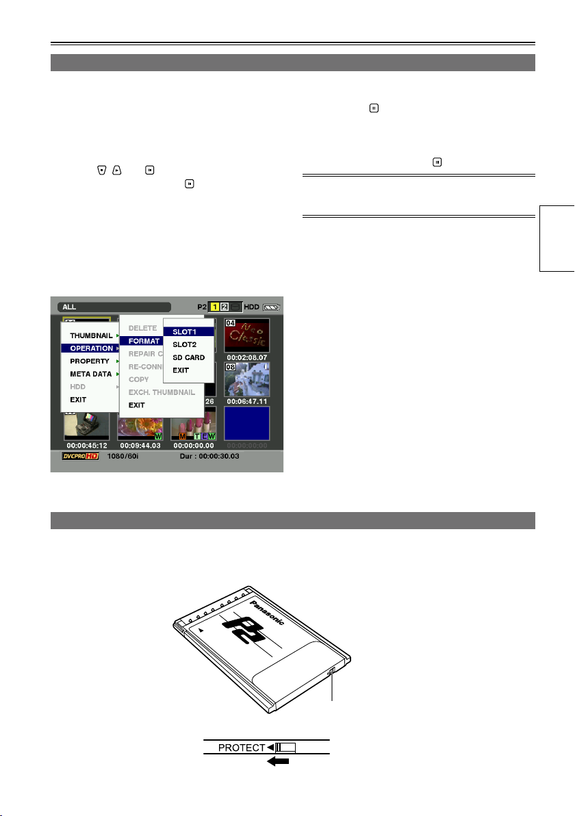
Formatting P2 cards
1 Hold down [POWER] for at least 1 second to
turn the power on.
The thumbnail screen now appears.
2 Press [MENU/MODE CHK].
3 Using , and , select “OPERATION”
– “FORMAT”, and press .
A screen such as the one shown below
•
now appears. Select the number of the slot
in which the P2 card to be formatted has
been inserted. If the card is not going to be
formatted, select “EXIT”.
If [MENU/MODE CHK] is pressed, the menu
•
display is cleared.
4 Select “YES” on the confirmation screen,
and press .
The selected P2 card is now formatted.
•
5 When the completion message has
appeared, press “OK” ( ).
If you format the P2 card, all the data saved on the
P2 card is deleted.
Preparations
P2 card protection
To prevent the data recorded on the P2 card from being deleted by mistake, set the write-protect switch on
the P2 card to PROTECT.
Write-protect
switch
29
Page 30
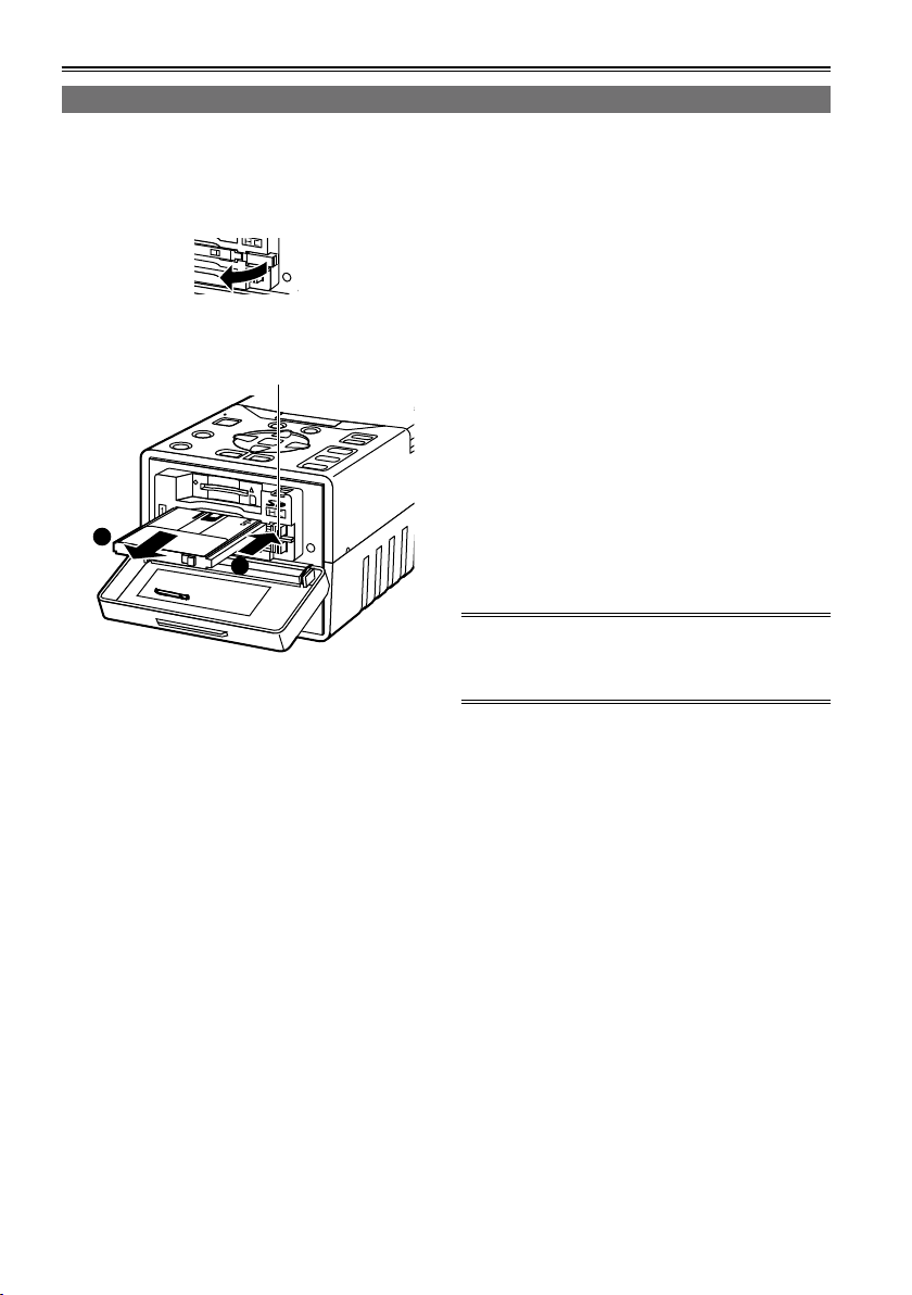
P2 cards (continued)
1
2
Ejecting P2 cards
1 Confirm P2 card access LED is not blinking
orange.
2 Open the card slot cover and raise the P2
card eject button.
3 Push the P2 card eject button to remove the
P2 card.
P2 card eject button
4 After ejecting the P2 card, close the card
slot cover.
Do not eject cards or turn off the power in the
•
following situations: otherwise, this may cause
P2 card trouble.
1) While the orange P2 card access LED is
changing from blinking to lighting after the P2
card has been inserted
2) During recording, during the process to
complete recording or while the P2 card
access LED is blinking
3) While the P2 card access LED is blinking
(i.e. while copying, formatting, etc.)
In the event that a P2 card is ejected while being
•
accessed or formatted, “TURN POWER OFF” is
displayed on the LCD monitor. In a case like this,
turn the power off and then turn it back on.
When a card was ejected while it was being
formatted:
Re-format the card.
When a card was ejected while its data was
being accessed:
Something may have gone wrong with one of the
clips (Page 35). Check the clips, and repair the
abnormal one. (For details on repairing clips →
Page 41)
During playback, a P2 card will not be recognized
•
even if it has been inserted into the other empty
slot, and the P2 card access LED will not
light. After playback is completed, the P2 card
recognition process is started.
If the P2 card is ejected while thumbnails are
•
displayed, the thumbnail display screen will be
cleared and the normal display screen appears.
Precaution for using P2 cards
P2 cards must always be formatted using a P2
device prior to use.
30
Page 31

P2 card recording durations
Capacity
4 GB Approx. 16 minutes Approx. 8 minutes Approx. 4 minutes
8 GB Approx. 32 minutes Approx. 16 minutes Approx. 8 minutes
16 GB Approx. 64 minutes Approx. 32 minutes Approx. 16 minutes
32 GB Approx. 128 minutes Approx. 64 minutes Approx. 32 minutes
64 GB Approx. 256 minutes Approx. 128 minutes Approx. 64 minutes
DVCPRO/DV
Audio 2/4CH
DVCPRO50
Audio 4CH
AVC-Intra50
Audio 8CH
DVCPRO HD
AVC-Intra100
Audio 8CH
*
* Native recordings such as 720p/30pN, 720p/24pN, 720p/25pN, 1080/30pN, 1080/24pN and 1080/25pN
are not available on this unit.
AJ-P2C002SG (2 GB) cards cannot be used.
•
The memory needed for management and other purposes is included in the memory figure displayed, so
•
the amount of memory you can use for recording is less than what is displayed.
The above chart shows continuous recording time for 1 clip in each capacity. Depending on the number
•
of clips, available recording time on the whole may be shorter that the above time.
Depending on the type of P2 card, you may need to update the driver installed in the unit. (Page 113)
•
Dividing clips over 4 GB in size
Dividing clips recorded on P2 cards
•
If, when a P2 card with a memory capacity of 8 GB or more is used in this unit, the continuous recording
time for a single session exceeds the time shown in the table below, the recording will automatically
continue as another clip. Furthermore, when performing thumbnail operations (such as display, delete,
repair or copy) for clips using the P2 device, these operations can be performed with all the clips treated
as a single clip. The clips may be displayed as separate clips with non-linear editing software and PCs.
Recording format Recording time
DVCPRO HD Approx. 5 minutes
DVCPRO50 Approx. 10 minutes
DVCPRO/DV Approx. 20 minutes
AVC-Intra100 Approx. 5 minutes
AVC-Intra50 Approx. 10 minutes
Preparations
31
Page 32

P2 cards (continued)
LOOP REC recording
With this function, when the recording buffer is full, the recording will loop back to the beginning and
new contents will start overwriting the older contents of the buffer. Using LOOP REC, the recording will
always consist of the most recent minutes recorded. The size of the recording buffer is determined by
the amount of available space on both of the P2 cards. To use LOOP REC function, set “LOOP REC” to
“ON” on the setting menu “RECORDING SETUP” screen. (Page 91)
Once the unit is turned OFF, LOOP REC function will be disabled (OFF) next time the unit is turned ON.
•
To perform LOOP REC, use P2 cards with remaining memory of 1 minute or more respectively.
•
While performing LOOP REC, all P2 card access LEDs light orange. If you remove either of the P2 card,
•
LOOP REC stops.
When the LOOP REC mode is active, “LOOP” is displayed on the first line of the screen display.
•
However, LOOP REC cannot be performed if only 1 card is inserted in the LOOP REC mode. In this
case, “P2 LACK” and “L-” blinks.
The remaining time for the P2 card in the LOOP REC mode is approximate.
•
Shot marks cannot be added or released during LOOP REC.
•
Text memos cannot be recorded during LOOP REC.
•
When selecting 1394 input, LOOP REC is not available.
•
■ToexittheLOOPRECmode
There are following 2 ways.
Set “LOOP REC” to OFF on the setting menu “RECORDING SETUP” screen.
•
Turn off the power.
•
Other
USER button
The following features are allocated to the buttons
at the time of shipping.
You can assign EXIT function to USER2 button
only as well as ALT function to USER3 button only.
For details, refer to the USER1-3 items (Page 97)
on the setting menu “SW MODE” screen.
USER1: SYS FORMAT
USER2: EXIT
USER3: ALT
The functions allocated to [USER] will be
•
displayed while [MENU/MODE CHK] on the
normal display screen is held down for at least 2
seconds.
Depending on the mode, allocated functions may
•
not be operable.
32
Charging the internal battery
The date (year/month/day) and time are stored in
the memory by the internal battery. When the
display has appeared on the LCD monitor screen,
it means that the internal battery charge is low.
Follow the steps below to charge the battery. After
the battery has been fully charged, set Year/Month/
Day and time.
1 Connect the AC adapter to the unit.
Keep the unit’s power turned off.
2 Maintain this condition for about 4 hours.
The internal battery will now be charged.
If appears even after the internal battery has
been charged, the battery must be replaced. Ask
your dealer for another battery.
Page 33

Using SD/SDHC memory cards
THUMBNAIL
OPERATION
PROPERTY
META DATA
HDD
EXIT
DELETE
FORMAT
REPAIR CLIP
RE-CONNECTION
COPY
EXCH. THUMBNAIL
EXIT
SLOT1
SLOT2
SD CARD
EXIT
USER files can be saved or loaded using SD or
SDHC memory cards (both types of cards will now
be referred to as “SD cards”). (Page 34)
In addition, if you save a meta-data upload file on
the SD card, it can be loaded and recorded as clip
meta-data. (Page 46)
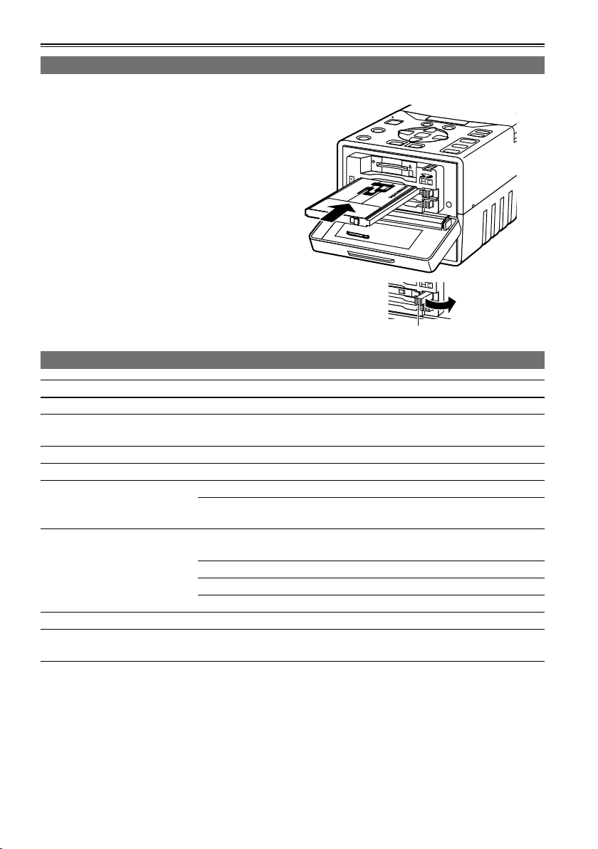
Inserting and removing the SD card
<Insertion>
1 Open the card slot cover, and insert the
card, making sure the SD card is oriented as
shown.
2 Close the card slot cover.
SD card
access
LED
4 Select “YES” on the confirmation screen,
and press .
• The selected SD card is now formatted.
5 When the completion message has
appeared, press “OK” ( ).
You can also format the SD card at the “SD
•
CARD FORMAT” item on the setting menu
“CARD FUNCTIONS” screen. (Page 105)
With SDHC cards, 32 KB of memory will have
•
already been used up.
Precaution for using SD cards
With this unit, use SD cards which meet the SD
standard or SDHC standard. Always remember to
<Removal>
1 Open the card slot cover, and confirm that
the SD card access LED is not lighted.
2 Push the center part of SD card and pull
straight out.
use this unit to format the SD cards. SD cards with
the following memory sizes can be used within this
unit.
SD (8 MB to 2 GB):
256 MB 512 MB 1 GB 2 GB
SDHC (4 GB to 32 GB):
3 Close the card slot cover.
Preparations
8 MB 16 MB 32 MB 64 MB 128 MB
4 GB 8 GB 16 GB 32 GB
Formatting SD cards
1 Hold down [POWER] for at least 1 second to
turn the power on.
2 Press [MENU/MODE CHK].
3 Using , and , select “OPERATION”
– “FORMAT” – “SD CARD”, and press .
If the card is not going to be formatted, select
•
“EXIT”.
To obtain the latest information which is not
provided in these Operating Instructions, access
the P2 support page on the web site below.
https://eww.pavc.panasonic.co.jp/pro-av/
When using the SD cards, always remember to
•
close the card slot cover.
Also refer to “Use of SD/SDHC memory cards”
•
on page 116.
33
Page 34

CARD FUNCTIONS
SD CARD FORMAT
USER FILE
RETURN
CHANGE
USER FILE (SD CARD)
FILE SELECT
READ
WRITE
FILE 1
FILE 2
FILE 3
FILE 4
>>>
>>>
1
TITLE1
TITLE2
TITLE3
TITLE4
>>>
TITLE RELOAD
USER FILE (SD CARD)
FILE SELECT
READ
WRITE
FILE 1
FILE 2
FILE 3
FILE 4
>>>
TITLE2
TITLE3
TITLE4
>>>
TITLE RELOAD
1
RETURN
CHANGE
WRITE FILE 1
NO
TITLE EDIT
TITLE1
USER FILE (SD CARD)
YES - - - -
PUSH SET
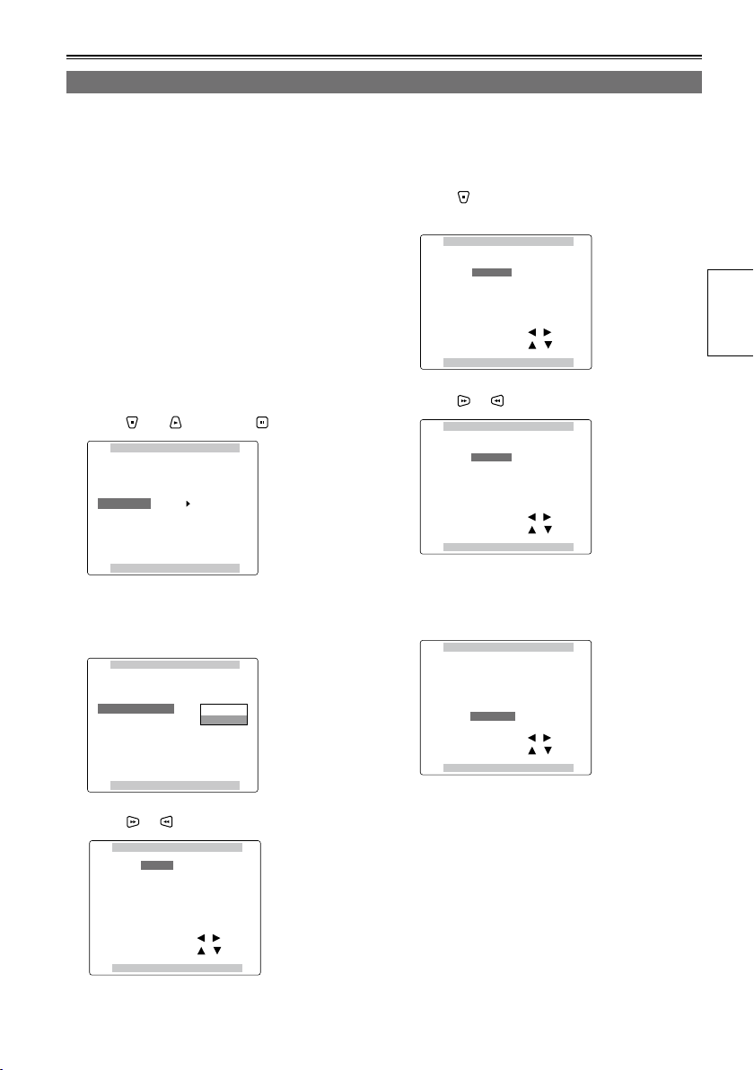
Saving USER files on SD cards
Up to four sets of settings can be saved as four
files on the SD card, and they can be loaded from
the card.
The menu setting value on the thumbnail display
•
screen cannot be saved or loaded.
1 Insert the SD card to the SD card slot.
2 Press [THUMBNAIL/MODE] to display the
normal display screen.
3 Press [MENU/MODE CHK].
4 Select “USER FILE” on the setting menu
“CARD FUNCTIONS”, select “CHANGE”,
and press .
Basic operations on the setting menus (Page 88)
•
5 Select “FILE SELECT”, and press .
6 Using or , select the file number (1 to 4),
and press .
9 Press [MENU/MODE CHK] four times to
display the normal display screen.
To give titles to files
1) Perform steps 1 to 7.
2) Select the characters using
move to the next character using .
The number of characters which can be input
•
is 8.
Any of the following characters can be input.
•
(Space), A to Z, 0 to 9, : ; < = > ? @ [ \ ] ^ _ -. /
All the characters can be deleted using the
•
unit’s [RESET] button.
3) After all the characters have been input, press
at the left end of the characters (or at the
right end), display “YES” using , and press .
After the data has been saved, “WRITE OK”
•
is displayed.
To load a file
1) Perform steps 1 to 6.
2) Move to “READ” using
and press .
The files are loaded.
•
3) If “TURN POWER OFF” appears after loading,
turn off the power, and then turn it back on. The
loaded files are now set.
To reload the files from the SD card:
1) Perform steps 1 to 4.
2) Using
and , move to “TITLE RELOAD”,
display “YES”, and press .
The files are now re-loaded.
•
and , and
and , display “YES”,
7
Using and , select “WRITE”, and press .
8 Display “YES” using and , and press .
In the figure below, “TITLE1” is the filename.
•
After the data has been saved, “WRITE OK”
•
is displayed.
The USER file which was written changes to
•
a white display.
34
If “WRITE NG FORMAT ERROR” is displayed,
•
format the SD card. (Page 33)
If “WRITE NG WRITE PROTECT” is displayed,
•
release the SD card protection.
If “WRITE NG CANNOT ACCESS” is displayed,
•
complete the other operations (such as playback),
and then proceed to operate.
If “WRITE NG ERROR” is displayed, the SD card
•
may be defective. Replace the card.
Page 35

Thumbnail display
THUMBNAIL OPERATION PROPERTY
ALL CLIP
SAME FORMAT CLIPS
SELECTED CLIPS
MARKED CLIPS
TEXT MEMO CLIPS
SLOT CLIPS
SETUP
EXIT
DELETE
FORMAT
REPAIR CLIP
EXCH. THUMBNAIL
RE-CONNECTION
COPY
EXIT
CLIP PROPERTY
CARD STATUS
DEVICES
PROPERTY SETUP
EXIT
HDD
EXPORT
EXPLORE
SETUP
EXIT
META DATA
LOAD
RECORD
USER CLIP NAME
INITIALIZE
PROPERTY
EXIT
The video data produced on a P2 card by a single shooting session is referred to as a clip. When the
unit’s power is turned on, the clips are displayed as thumbnails on the LCD monitor. (If there are many
clips, it will take a few moments for all the clips to be displayed)
Playback formats
The formats which can be played back by this unit are as follows.
This unit cannot necessarily play back all the following formats simultaneously. Only the formats that
support the setting menu “SYSTEM FREQ” can be actually played back.
AVC-Intra100, AVC-Intra50
1080/60i
1080/50i
1080/30pN (native recording)
1080/24pN (native recording)
1080/25pN (native recording)
720/60p
720/30pN (native recording)
720/24pN (native recording)
720/50p
720/25pN (native recording)
DVCPRO HD
1080/60i (30p over 60i, 24p over 60i, 24pA over 60i)
1080/50i (25p over 50i)
720/60p (30p over 60p, 24p over 60p)
720/30pN (native recording)
720/24pN (native recording)
720/50p (25p over 50p)
720/25pN (native recording)
DVCPRO50/25, DV
480/60i (30p over 60i, 24p over 60i, 24pA over 60i)
576/50i (25p over 50i)
*
24p, 30p, 60p and 60i operate with the actual frequencies of 23.98p, 29.97p, 59.94p and 59.94i respectively.
*
*
*
*
*
*
*
*
Preparations
Playback
Names and functions of thumbnail display screen parts
Menu configuration of thumbnail display screen (until the second hierarchy)
(Continued on the next page)
35
Page 36

Thumbnail display (continued)
1 2
P2 HDD
1 2
1 2
1 2
2
1
4
3
5
6
7
15
8 9
10 11 12 13 14
Names and functions of thumbnail display screen parts (continued)
1 Display statuses
The types of information which are displayed on
the screen are displayed as follows.
ALL: All clips
SAME FORMAT: Clip whose format is the
SELECT: Clip selected by the STILL/
MARKER: Clip to which the shot mark
TEXT MEMO: Clip with text memo data
SLOT n: Clip on the P2 card in slot
PROPERTY: Detailed clip information
P2/REMAIN:
P2/USED:
META DATA: meta-data set on this unit
same as the system format
SET button
has been added
“n”
Media information
(remaining memory)
Media information
(used memory)
When you select SDI on the setting menu
“INPUT SELECT” and input a signal into SDI
input connector, input the same signal as the
one set on the setting menu “SYS FORMAT”. If
you input a signal with the different format, the
thumbnail display will be distorted also.
2 P2 card slot numbers and hard drive
statuses
• P2 card
The numbers of the P2 card slots
(Gray)
(White)
(Yellow)
*
The frame is displayed in pink when the inserted
P2 card is in one of the following statuses:
RUN DOWN CARD (Page 84)
•
The maximum number of overwrites on the P2
card has been exceeded.
DIR ENTRY NG CARD (Page 83)
•
The directory structure on the P2 card is not
supported.
where P2 cards have not been
inserted are displayed in gray.
The numbers of the P2 card slots
*
where P2 cards have been inserted
are displayed in white.
The number of the P2 card slot,
which contains a P2 card with a clip
that has its cursor position recorded,
is displayed in yellow. When a single
*
clip has been recorded on a multiple
number of P2 cards, all the slot
numbers of the cards on which the
clip is recorded will be displayed in
yellow.
36
Page 37

• HDD
?
M
P
T
E
w
When a mode other than the USB
HOST mode is established or when
(Gray)
(White)
(Yellow)
(Red)
the USB HOST mode is established
but the hard drive is not connected,
this status is displayed in gray.
When the USB HOST mode is
established and the hard drive that
can be used is connected, this
status is displayed in white.
When the USB HOST mode is
established and the clips on the hard
drive are displayed as thumbnails,
this status is displayed in yellow.
When the USB HOST mode is
established and the hard drive is not
in the data copy enable status, this
status is displayed in red.
3 Clip information display
Depending on what has been set on the
thumbnail display screen (Page 39), the
time code at the clip recording start point or
the user’s bit, shooting time, shooting date,
shooting date/time, USER CLIP NAME or
SLOT number is displayed.
4 Clip format
The compression format, video recording
format and frame rate of the clip where the
cursor is positioned is displayed.
5 Duration
The length of the clip where the cursor is
positioned is displayed.
6 USB HOST mode indicator
This appears when the USB HOST mode has
been selected.
7 Clip number
These are the numbers which have been set
by the unit for all the correctly recognized clips
on a P2 card. The numbers are allocated in
sequence starting from the earliest shooting
date/time. The clips which cannot be played
back are displayed in red.
8 X Defective clip indicator
Unknown clip indicator
This indicates clips whose recording contains
problems for reasons such as the power being
cut off while they were being recorded. It may
be possible to repair clips which are indicated
by the yellow defective clip indicator. For further
details, refer to “Repairing defective clips”
(Page 41). It is not possible to repair clips which
are indicated by the red defective clip indicator
so delete them. If these clips cannot be deleted,
format the P2 card. In the case of formats
incompatible with this unit, ? is displayed
instead of X.
9 ! Incomplete clip indicator
This appears when a single clip has been
recorded onto a multiple number of P2 cards
and one of the P2 cards concerned has not
been inserted into the P2 card slot.
10
Shot mark indicator
This is indicated on the clips of which a shot
mark has been added to their thumbnails.
11
Clip-with-proxy indicator
This indicates clips for which a proxy has been
additionally recorded.
12
Text memo indicator
This indicates clips with text memo data.
13
Edit-copy clip indicator
This indicates clips which have been editcopied by the AJ-HPM110 or other model which
supports the edit-copy function. For details on
the edit-copy function, refer to the operating
instructions of the model which supports the
function.
14
Wide indicator
This indicates clips which have been recorded
using the 16:9 aspect ratio. It does not indicate
clips which were formatted by a hard drive.
15
Remaining battery charge display
As the remaining charge drops, the display
changes in the following sequence:
and .
When the charge is virtually depleted, the
(or ) display changes to red.
(While the AC adapter is being used, a display
other than may appear: this is normal
and not a sign of trouble)
Playback
37
Page 38

Thumbnail display (continued)
Changing the displays on the thumbnail display screen
You can customize the thumbnail display screen to better suit your operating needs for more efficient
operation.
1 Display the thumbnail display screen.
2 Press [MENU/MODE CHK].
3 Using , and , select the type of
clip to be displayed at the lower level of
“THUMBNAIL”, and press .
ALL CLIP: Select this to display all the clips.
SAME FORMAT
CLIPS:
SELECTED CLIPS: Select this to display the clips selected by the STILL/SET button.
MARKED CLIPS: Select this to display the clips to which shot marks have been added.
TEXT MEMO
CLIPS:
SLOT CLIPS: Select this to display the clips on the P2 card of slot number “n”.
SETUP: This enables you to change the display of the thumbnail indicators, data displays and
EXIT: Select this to return to the previous menu.
Select this to display the clips whose format is the same as the system format.
Select this to display the clips with text memo data.
other settings.
38
Page 39

Setting the items to be displayed
You can customize how the thumbnails are to be displayed to better suit your intended application. This
enables you to change the display of the thumbnail indicators, data displays and other settings.
1 Display the thumbnail display screen.
2 Press [MENU/MODE CHK].
3 Using , and , select the item to be
set at the lower level of “THUMBNAIL”
– “SETUP”, and press .
INDICATOR: This menu item enables you to set
DATA
DISPLAY:
the indicator on the thumbnail to be
displayed/not displayed.
ALL HIDE If selected, none of the
MARKER Shot mark indicator
TEXT
MEMO
WIDE Wide indicator
PROXY Proxy indicator
This menu item enables you to select
what is to be displayed in the clip
information display (Page 37).
TC Time code
UB User’s bit
TIME Time of recording
DATE Date of recording
DATE TIME
USER
CLIP
NAME
SLOT Slot number
indicators are displayed.
If not selected, the
indicators are displayed
in line with the settings of
the menu items below.
Text memo indicator
Date/time of recording
Up to 15 characters from
the beginning of the user
clip name are displayed.
(When displayed in English)
DATE
FORMAT:
THUMBNAIL
SIZE:
PLAYBACK
RESUME:
THUMBNAIL
INIT:
SORT: This menu item enables you to
EXIT: Select this to return to the previous
This menu enables you to select the
display format for recording date.
Y-M-D Year/month/day
M-D-Y Month/day/year
D-M-Y Day/month/year
• This setting will also be reflected
in the preparation dates of the file
displays such as the dates of the
recordings which are displayed
as one of the clip properties, the
dates of the recordings which are
displayed when DATE has been
selected as the DATA DISPLAY
item setting, and the loading dates
of the meta-data.
This menu item enables you to select
the size of the thumbnails which will
be displayed on screen.
LARGE Large size (The
thumbnail is displayed
with width 3 x length 2)
NORMAL Standard size (The
thumbnail is displayed
with width 4 x length 3)
When the cursor was not moved from
the clip where playback was stopped,
the next playback starts from that
stopped position.
ON Select “ON” to play back
from the stop position.
OFF Select “OFF” to play
back the clip from its
beginning.
This menu item enables you to return
the thumbnail display settings to the
factory settings.
set the order of clip display in the
thumbnail display.
OFF Normal
SLOT Sort the order of display
by the slot number
menu.
Playback
The underlined settings are the factory mode settings.
39
Page 40

Clip management
Selecting clips
When performing operations on the thumbnail display screen, select the clip which will be the target of
these operations as follows.
1 Using , , or , move the cursor (yellow
frame) to the target clip.
To move the cursor to left or right, use or .
You can also use or by pressing and holding
[ALT/3].
To move the cursor up and down, use or by
pressing and holding [ALT/3].
This operation on the rest of the pages in this
manual is referred to as “cross cursor operation”.
2 Press .
A bluish-green frame now appears at the clip
where the cursor is positioned to indicate that the
clip has been selected.
To allocate functions to the USER buttons, refer to “USER button” (Page 32).
•
[ALT/3] does not work when ALT function is not allocated to [ALT/3].
•
By repeating steps 1 and 2, you can select a multiple number of clips.
•
If you select a clip and move the cursor to another clip, and then press while pressing and holding
•
[ALT/3], you can select from the last selected clip until the clip at the cursor position at a time.
To move from one page to another, press or of .
•
To release the selection
1 Move the cursor to the selected clip, and press again.
The selection is released.
By pressing [EXIT/2] while pressing [ALT/3], you can cancel the selection of the selected clips all together.
•
Deleting clips
You can delete unwanted clips from the P2 card by proceeding as follows.
1 Display the thumbnail display screen.
2 Select the clips to be deleted.
3 Press [MENU/MODE CHK].
4 Using , and , select “OPERATION”
– “DELETE”, and press .
5 Select “YES”, and press .
6 When the completion message has
appeared, press “OK” ( ).
It may not be possible to delete clips for which the X defective clip indicator or ? unknown clip indicator is
•
displayed.
40
Page 41

Repairing and connecting clips
Repairing defective clips
The defective clip indicator (yellow X) appears
in order to indicate that there is a problem in the
clip such as the power having been suddenly cut
off while it was being recorded. You can repair
problem clips by proceeding as follows.
1 Display the thumbnail display screen.
2 Select the clip to be repaired.
3 Press [MENU/MODE CHK].
4 Using , and , select “OPERATION”
– “REPAIR CLIP”, and press .
5 Select “YES”, and press .
It is not possible to repair clips with some types
•
of damage. These kinds of clips are identified by
the red X.
Connecting incomplete clips
In some cases, clips recorded on a multiple
number of P2 cards may not be recognized as
a single continuous clip and may be recognized
as an incomplete clip (! indicator) instead. At
times like this you can use the connecting function
to restore the “incomplete” clip to a continuous
(originally connected) clip.
1 Display the thumbnail display screen.
2 Select the incomplete clip to be connected.
3 Press [MENU/MODE CHK].
4 Using , and , select “OPERATION”
– “RE-CONNECTION”, and press .
5 Select “YES”, and press .
A clip is recognized as incomplete when:
A clip recorded on a multiple number of P2 cards
•
has been copied separately from one card and
then from another or other cards.
A clip recorded on a multiple number of cards
•
has first been copied separately from one card
and then from another or other cards onto a hard
drive and then written back onto the P2 cards.
A long clip lasting more than 5 minutes in the
•
AVC-Intra100 or DVCPRO HD format (10 or
so minutes in the AVC-Intra50 or DVCPRO50
format, or 20 or so minutes in the DVCPRO or
DV format) has first been copied to a hard drive
and then written back onto the P2 cards.
Playback
Normally, thumbnails with the incomplete clip
•
indicator are displayed side by side.
If only parts of incomplete clips separated into 3
•
or more have been connected, the incomplete
clip indicators will remain on the screen until
all the clips which make up the original clip are
connected.
41
Page 42

Clip management (continued)
?
Copying clips
Clips can be copied onto the P2 card in the other P2 card slot.
While clips are being copied, do not turn off the power or eject the card. Otherwise, defective clips will be
•
produced. If defective clips are produced, delete them, and copy the original clips again.
Copy incomplete clips after having connected them.
•
1 Display the thumbnail display screen.
2 Select the clip to be copied.
3 Press [MENU/MODE CHK].
4 Using , and , select “OPERATION”
– “COPY” – “SLOT n” (where “n” is the
number of the P2 card slot into which the
copy destination P2 card was inserted), and
press .
5 Select “YES”, and press .
Clip copying now starts.
To stop the copying process at any time, press
•
and select [YES] to cancel the copying. The
partially copied clip at the copy destination will
be deleted.
If there is a clip with the same GLOBAL CLIP ID--
•
one which, for instance, was previously copied to
the copy destination--“OVER WRITE” will appear.
To overwrite the existing clip, select “YES” or to
cancel the overwriting, select “NO”, and press .
(When you copy some portion of a clip which has
been recorded on a multiple number of P2 cards,
“OVER WRITE” also appears when copying the
remaining portion of the clip.)
6 When the completion message has
appeared, press “OK” ( ).
Clips cannot be copied when any of the following
error messages are displayed.
“LACK OF REC CAPACITY!”
•
Clips will not be copied because there is not
enough space left on the destination P2 card.
“UNKNOWN CONTENTS FORMAT!”
•
Clips will not be copied because the selected
clips include defective clips.
“NO COPY TO SAME CARD!”
•
Clips will not be copied because an attempt is
being made to copy clips to the same card.
“TOO MANY CLIPS!”
•
Clips will not be copied because too many clips
have been selected.
You can extract and copy a portion or subset of
•
a clip. If you start copying while selecting a text
memo at the bottom of the text memo screen, the
block between the selected text memo position
and the next text memo is copied. If there is no
text memo after the selected text memo, the
block from the text memo position to the end of
the clip will be copied.
Clips displayed by the X defective clip indicator
•
cannot be copied.
It may not be possible to copy clips for which the
•
unknown clip indicator is displayed.
42
Page 43

Displaying the clip information
1)
2)
3)
4)
5)
V
You can display detailed information about clips on the screen, and check it.
1 Display the thumbnail display screen.
2 With cross cursor operation, move the
cursor to the target clip.
3 Press [MENU/MODE CHK].
4 Using and , select “PROPERTY”, and
press .
5 Select “CLIP PROPERTY” on the sub-menu
displayed, and press .
Information on the target clip now appears on the
screen.
1) Information added to clips (Page 37)
The indicators or numbers of text memos or
voice memos, which have been added into
clips, are displayed. In addition, when a P2 card
on which clips have been recorded has been
write-protected, the mark is displayed.
Voice memo indicator
•
This is displayed on clips to which voice memos
have been added. It appears only in the clip
property mode.
Voice memos cannot be recorded or played back
•
using this unit.
2) Clip number
3) Thumbnail
4) Clip information
The following information is displayed.
CLIP NAME: The filename of the clip as
recorded on the P2 card
START TC: Time code when recording was
started
START UB: User ’s bit when recording was
started
DATE: Date on which the clip was
recorded
TIME: Time at which the clip was
recorded
DURATION: Length of the clip
V_FORMAT: Recording format of the clip
FRAME RATE: Playback frame rate
REC RATE: Recording frame rate (displayed
for clips specially recorded by
the camera recorder (i.e. VFR
recording))
When or is pressed, the information of the
previous or next clip is displayed.
5) Clip meta-data
Items for referencing the detailed information
on the clips (clip meta-data) are displayed.
(Continued on the next page)
Playback
43
Page 44

Clip management (continued)
Displaying the clip information (continued)
6 If necessary, reference the clip meta-data
contents.
When the clip meta-data item is selected using
and , and then is pressed, the following
information is displayed.
GLOBAL CLIP
ID:
USER CLIP
NAME:
VIDEO: Video signal system, etc. (frame rate,
AUDIO: Audio channel system, etc. (sampling
ACCESS: Last update date, etc.
DEVICE: Serial number of device used to
SHOOT: Recording start and end dates, etc.
SCENARIO: Program name, scene number, etc.
A unique number which is not
assigned to any other clips
Clip name which can be assigned by
the user
Normally, the GLOBAL CLIP ID is
provided as the clip name.
pull-down, aspect ratio)
rate, bit rate)
(name of the person who created
the clip and date on which it was
created, date on which the clip was
last updated and name of the person
who last updated the clip)
record the clip, etc. (name of the
device manufacturer, serial number,
model number)
(name of person who shot the clip,
date on which shooting started, date
on which shooting ended, shooting
location information, altitude,
longitude, latitude, shooting location
information source, shooting location)
(program name, scene number, take
number)
NEWS: Reporter, news-gathering object, etc.
MEMO: Text memo number, recording
THUMBNAIL: Information on the thumbnail images
(reporter, purpose of news gathering,
object of news gathering)
position, name, text content
• The recording position is indicated
by the number of frames from
the beginning. On a thumbnail
text memo display, this recording
position is indicated as a time code
instead.
• Texts consisting of up to 1000
characters can be attached, but
only the first 100 characters will
actually be displayed.
or is used to move from one
•
text memo number to another.
The frame positions and sizes (offset
value from the beginning of the clip,
height and width) of the thumbnail
source images are displayed.
7 Press [MENU/MODE CHK], and select
“EXIT” to exit.
44
Page 45

Editing the clip information
060A2B340101010501010D4313000000C2A90ADE46
1505F00080458200000002
1 2 3 4 5 6 7 8 9 0 SP BS
q w e r t y u i o p - Caps
a s d f g h j k l . _ OK
EXIT
z x c v b n m
USER CLIP NAME : 05F00080458200000002
USER CLIP NAME :
You can edit the detailed clip information (clip meta-data).
1 Display the thumbnail display screen.
2 With cross cursor operation, move the
cursor to the target clip.
7 The soft keyboard screen now appears.
With cross cursor operation, select
characters to be input, and while entering
them using , edit the information.
3 Press [MENU/MODE CHK].
4 Using , and , select “PROPERTY”
– “CLIP PROPERTY”, and press .
The clip information is displayed.
•
5 Using and , select the item to be edited,
and press .
6 The window with the items to be edited now
appears so select an item using and ,
and then press .
8 Select “OK” with cross cursor operation,
and press to quit editing.
To edit another item, repeat steps 6 to 8.
•
9 Using and , select “OK” to exit the item
display.
10 Press [MENU/MODE CHK], and select
“EXIT” to exit the clip information screen.
You can edit the following information.
USER CLIP NAME This displays the name of the clip which
has been set by the user; the global clip ID
is set as the default value.
ACCESS CREATOR Name of the person who did the recording
SHOOT SHOOTER Name of the person who did the shooting
LOCATION ALTITUDE Altitude of the shooting location
LONGITUDE Longitude of the shooting location
LATITUDE Latitude of the shooting location
PLACE NAME Place name
SCENARIO PROGRAM NAME Program name
SCENE NO. Scene number
TAKE NO. Take number
NEWS REPORTER Name of the reporter
PURPOSE Purpose of the news gathering
OBJECT Object of the news gathering
MEMO PERSON Name of the person who recorded the text
memo which was added to the clip
TEXT Content of the text memo
Playback
To modify the meta-data of clips displayed by the incomplete clip indicator !, insert the P2 card on which
•
the remaining clips were recorded.
Attached memo items of 100 characters or more cannot be modified.
•
When editing “LONGITUDE” or “LATITUDE”, or is sometimes used to move to the item.
•
“LONGITUDE” and “LATITUDE” cannot be deleted separately. To delete, set “ALTITUDE” to blank.
•
45
Page 46

Clip management (continued)
Adding the meta-data to clips
If the meta-data upload file which contains the name of shooter or reporter, shooting location or text memo
information is saved on the SD card, it can be loaded and recorded as clip meta-data.
Create the meta-data upload file on a PC
↓
Save it on a SD card
↓
Load the meta-data upload file onto this unit
↓
When images are recorded, the meta-data is added to the clip.
Preparation of the meta-data upload file
You can create the meta-data upload file on a PC using the P2 viewer (the latest updated version). You
can also create meta-data upload files using the P2 Contents Management System (P2CMS) software, on
either a Windows or Macintosh computer.
The P2 viewer is an application to operate clips recorded on the P2 card. Distributed as free software, this
is used on a Windows PC.
https://eww.pavc.panasonic.co.jp/pro-av/
Install the P2 viewer or P2 Contents Management System (P2CMS) software (the latest updated version)
to PC, create the meta-data upload file and write it onto the SD card.
P2 viewer must be the latest updated version.
•
For details on creating the meta-data upload file, refer to Help section of the P2 viewer.
For SD cards, refer to page 33.
46
Page 47

Setting to add meta-data
Make the setting to load the meta-data upload file onto this unit
■ SelectthemethodtorecordUSERCLIPNAME
Set the recording method of USER CLIP NAME.
1 Display the thumbnail display screen.
2 Press [MENU/MODE CHK].
3 With cross cursor operation, move the cursor to “META DATA”–“USER CLIP NAME”.
4 Move the cursor to “TYPE1” or “TYPE2” and press .
Recording method USER CLIP NAME to be recorded
Use clip meta-data
Not use clip meta-data
*
When the meta-data upload file has been loaded, but “META DATA”–“RECORD” is “OFF”
*
TYPE1 Loaded meta-data setting value
TYPE2 Loaded meta-data setting value + COUNT value
TYPE1 The same as GLOBAL CLIP ID
TYPE2 The same as CLIP NAME
Playback
5 Press [MENU/MODE CHK] to end the procedure.
(Continued on the next page)
47
Page 48

Clip management (continued)
Adding the meta-data to clips (continued)
COUNT value
COUNT value is displayed in 4-digit number. COUNT value is added by 1 increment every time a new clip
is generated by P2 card recording after the recording method of “USER CLIP NAME” is set to “TYPE2”
and the clip meta-data is loaded.
■ ResettingtheCOUNTvalue
You can reset the COUNT value according to the following operation.
1 Display the thumbnail display screen.
2 Press [MENU/MODE CHK].
3 With cross cursor operation, move the cursor to “META DATA”–“PROPERTY”–“USER CLIP
NAME” and press .
48
Page 49

4 With cross cursor operation, move the cursor to “COUNT RESET” and press .
The COUNT value is reset to 1.
5 Press [MENU/MODE CHK] or [EXIT/2] to end the procedure.
(Continued on the next page)
Playback
49
Page 50

Clip management (continued)
Adding the meta-data to clips (continued)
How the COUNT value of USER CLIP NAME is added when the data exceeds 4 GB
In the following cases, 1 shot is recorded as multiple clips and the COUNT value is added by 1 increment
and recorded.
When a P2 card with the capacity of over 8 GB is used and the continuous recording at a time exceeds a
•
certain period of time
For further details, refer to “Dividing clips over 4 GB in size” (Page 31).
When 1 recording straddles 2 cards and is recorded on both cards
•
Furthermore, when performing thumbnail display and property display using the P2 device, Clip 1’s
thumbnail and COUNT value are displayed.
Loading the meta-data setting value
You can load the meta-data setting value from the SD card according to the following operation.
1 Insert the SD card containing the meta-data upload file into this unit.
2 Display the thumbnail display screen.
3 Press [MENU/MODE CHK].
4 With cross cursor operation, move the cursor to “META DATA”–“LOAD” and press .
The file name of the meta-data upload file in the SD card is displayed.
5 With cross cursor operation, move the cursor to the file to be loaded and press .
6 Move the cursor to “YES” and press .
The meta-data is loaded.
7 Press [MENU/MODE CHK] to end the procedure.
50
Page 51

Checking and revising the loaded meta-data
You can check and revise the meta-data loaded from the SD card.
1 Press [THUMBNAIL/MODE].
The thumbnail screen appears on the LCD monitor.
2
Press [MENU/MODE CHK] to select “META DATA”–“PROPERTY” from the thumbnail menu.
The following screen appears.
3 With cross cursor operation, move the cursor and press .
You can check each setting content of the loaded meta-data.
Playback
4 While checking each setting content of the meta-data, move the cursor with cross cursor
operation to the item for which you wish to change the setting content and press .
The soft keyboard screen appears. Now, you can change the setting. (Page 45)
(Continued on the next page)
51
Page 52

Clip management (continued)
Adding the meta-data to clips (continued)
Checking and revising the loaded meta-data (continued)
With cross cursor operation, move the cursor to the item of meta-data you wish to check and press .
Then the information is displayed.
USER CLIP NAME: User clip name
CREATOR: Creator
LAST UPDATE PERSON: Last update person
SHOOT: Shooter
PLACE NAME: Shooting place
SCENARIO: Program name, scene number, take number
NEWS: Reporter, purpose of news gathering, object of news gathering
MEMO: Memo input person, text information
•
After checking the content, press [EXIT/2] or
The information screen disappears.
To finish the setting change procedure, select “OK”
•
.
5 Press [MENU/MODE CHK] to end the procedure.
Deleting the meta-data
You can delete the meta-data saved in this unit according to the following operation.
1 Display the thumbnail display screen.
2 Press [MENU/MODE CHK].
3 With cross cursor operation, move the cursor to “META DATA”–“INITIALIZE” and press .
4 Move the cursor to “YES” on the confirmation screen and press .
The meta-data will be deleted.
5 Press [MENU/MODE CHK] to end the procedure.
52
Page 53

Recording clips to which the meta-data was added
You can add the loaded meta-data to clips when recording clips.
1 Display the thumbnail display screen.
2 Press [MENU/MODE CHK].
3 With cross cursor operation, move the cursor to “META DATA”–“RECORD”.
4 Move the cursor to “ON” and press .
With this setting, you can record video and the loaded meta-data at the same time. USER CLIP NAME
is added as meta-data according to the set recording method.
5 Press [MENU/MODE CHK] to end the procedure.
Playback
6 Recording video on this unit.
If you set “OFF” in step 4, meta-data is not added to the clip.•
53
Page 54

Clip management (continued)
1
)
4
)
5
)
2
)
3
)
1
)
4
)
2
)
3
)
5
)
Adding shot marks to clips
You can differentiate one clip from all the other clips by adding shot marks.
1 Display the thumbnail display screen.
2 With cross cursor operation, move the cursor to the target clip.
3 Press [USER] in which the shot mark function was allocated. (Page 32)
To release a shot mark, repeat the above steps.
If the video data created by a shooting session consists of a multiple number of clips, it will not be
possible to add or release the shot marks unless all the P2 cards containing the video data are inserted
into the slots.
Shot marks cannot be added into the clips on a card whose write protect switch is at the PROTECT
•
position.
Shot marks can be added during recording as well. (Page 63)
•
Shot marks cannot be added or released during playback.
•
Shot marks cannot be added or released during LOOP REC.
•
Displaying the P2 card status
The statuses of the P2 card slots, operation statuses of the P2 cards and other card information can be
displayed on the screen, and checked.
1 Display the thumbnail display screen.
[When REMAIN has been selected]
2 Press [MENU/MODE CHK].
3 Using , and , select “PROPERTY”
– “PROPERTY SETUP” – “P2 CARD CAP”,
and press .
4 Use and to select the item to be set,
and press .
REMAIN: Remaining memory display
USED: Used memory display
(default value)
5 Press .
6 Using and , select “CARD STATUS”,
and press .
54
[When USED has been selected]
Page 55

1) Write-protect mark
BRAND
MODEL NO.
SERIAL NO.
USER ID
: Panasonic
: AJ-P2C032RG
: AAF07L0520
:
OK
The mark is displayed when a P2 card is
write-protected.
2) P2 card status
With the remaining memory display, the P2
card’s remaining memory is indicated using
a meter and as a percentage. With the used
memory display, the P2 card’s used memory is
indicated using a meter and as a percentage.
Depending on the status of the card, one of the
following messages may be displayed.
FORMAT
ERROR:
NOT
SUPPORTED:
NO CARD: A P2 card has not been
An unformatted P2 card has
been inserted.
A card which is not supported
by the unit has been inserted.
inserted.
P2 card details display
When the cursor is moved to the slot whose P2
card status is displayed and is pressed, the
model number of the P2 card and other detailed
information on the card will be displayed. When
is pressed again, the detailed information is
cleared.
The card details are displayed as follows.
3) P2 card remaining memory (or used
memory) and total memory
A figure representing the remaining memory
(or used memory) of P2 cards/total memory
is displayed in minute equivalent. Fractions of
a minute are discarded so that the total of the
remaining memory (or used memory) on each
P2 card may not exactly correspond to the total
memory.
4) Slot remaining memory (or used memory)
total
A figure representing the total for the remaining
memory (or used memory) of the cards in the
two P2 card slots is displayed.
The free memory of a write-protected P2 card
•
is not included in the remaining memory.
5) P2 card warning displays
is displayed when the P2 card is in one of
the following statuses:
Details of the warnings can be checked on the
P2 card details display.
•
RUN DOWN CARD:
The maximum number of overwrites on the
P2 card has been exceeded.
•
DIR ENTRY NG:
The directory structure on the P2 card is not
supported.
Playback
55
Page 56

Clip management (continued)
Displaying SD card information
You can display the usage statuses of SD cards on the screen, and check them.
1 Display the thumbnail display screen.
2 Press [MENU/MODE CHK].
3 Using , and , select “PROPERTY”
– “DEVICES” – “SD CARD”, and press .
The following information is displayed.
SD STANDARD: Whether the SD card has
USED: Used memory [bytes]
BLANK: Free memory [bytes]
TOTAL: Total memory [bytes]
NUMBER OF
CLIPS:
PROTECT: Write-protect status
Proxy recording is not possible with this unit.
•
been formatted in compliance
with the SD/SDHC standard is
displayed.
SUPPORTED: The card format
complies with the SD/SDHC
standard.
NOT SUPPORTED: The card
format does not comply with the
SD/SDHC standard.
Number of clips contained on
the SD card when the clips
were copied onto the SD card
with a proxy or P2 camerarecorder
4 Press .
5 Press [MENU/MODE CHK] to exit the
procedure.
56
Page 57

Clip playback
Playing back clips
1 Display the thumbnail display screen.
2 With cross cursor operation, move the
cursor (yellow frame) to the target clip.
3 Press .
Playback starts from the clip where the cursor
is positioned. When this clip has finished
playing back, the subsequent clips are played
back in turn, and when the last clip has been
played back, the thumbnail screen is restored.
When “TEXT MEMO” is allocated to [USER]
•
(Page 97), text memos can be added during
playback. (but shot marks cannot be added)
When playing back a clip, there is no need to select it (provided that the bluish-green frame is displayed
•
on the thumbnail).
It is not possible to play back clips for which the X defective clip indicator or ? unknown clip indicator
•
(Page 37) is displayed.
The clips whose clip numbers are displayed in red cannot be played back.
•
By changing the thumbnail display setting (Page 38), you can play back only the clips you have selected,
•
or play back only the clips in which text memos have been inserted, for instance.
If you press while playing back the clip, the playback stops and the thumbnail screen is restored.
•
If the playback is stopped, the cursor position moves to the clip played back just before this clip.
•
The next playback start position is determined according to the setting menu: “THUMBNAIL”–“SETUP”–
•
“PLAYBACK RESUME” (Page 39).
If you play back various formats (AVC-Intra100, AVC-Intra50, DVCPRO HD, DVCPRO50, DVCPRO, DV),
•
the images and sounds are distorted between clips. This is not a malfunction.
Easy playback of clips stored on the external hard drive is available also. Refer to “Easy playback of clips
•
on the hard drive (For viewing materials)” on page 78.
If you change the thumbnail display screen to the text memo display, you can start playback from the text
•
memo position. Refer to “Playback from the text memo position” on page 60.
The unit does not support hot swap playback (Switching cards while playing back the continuously
•
recorded clips which were recorded onto multiple cards).
If the clips in AVC-Intra50 and AVC-Intra100 formats are played back, they are not output to the
•
DVCPRO/DV input/output connector (IEEE1394).
Playback
(Continued on the next page)
57
Page 58

Clip playback (continued)
Playing back clips (continued)
Play ( )
When this button is pressed during stop, playback begins from the start of the selected
clips*. When it is pressed during playback, the variable-speed playback (Page 59) is set,
and the clips are played back at the 1x speed.
*
If you do not move the cursor when “PLAYBACK RESUME” is “ON”, the playback
starts from the last stop position.
Rapid forward playback ( )
When this button is pressed during playback, the clip currently selected is played rapidly
in the forward direction (at 4x normal speed). When the thumbnail display screen is not
displayed, this type of playback is possible even during stop. If the button is held down,
the playback speed is increased.
menu “PLAYBACK FUNCTIONS” is set.) When it is pressed during pause, the next clip or
text memo is selected for playback. (Depends on the setting for the “SEEK POS” item on
the setting menu “PLAYBACK FUNCTIONS”.)
Rapid reverse playback ( )
When this button is pressed during playback, the clip currently selected is played rapidly
in the reverse direction (at 4x normal speed). When the thumbnail display screen is not
displayed, this type of playback is possible even during stop. If the button is held down,
the playback speed is increased. (The setting value for “SPEED MAX” on the setting
menu “PLAYBACK FUNCTIONS” is set.) When it is pressed during pause, the previous
clip or text memo is selected for playback. (Depends on the setting for the “SEEK POS”
item on the setting menu “PLAYBACK FUNCTIONS”.)
Stop ( )
If you press during playback, the playback stops and the thumbnail display screen is
restored.
Basic playback operations
(The setting value for “SPEED MAX” on the setting
Pause ( )
When this button is pressed again, playback is resumed.
Single clip playback
When “ONE CLIP” is assigned to [USER] (Page
97), if you press the [USER], only the clip at the
cursor position can be played back.
58
When the single clip playback finishes or you
•
press , the playback stops and the thumbnail
display screen is restored. The cursor moves to
the next clip.
During the single clip playback, all buttons but
•
are disabled.
The single clip playback starts from the beginning
•
of the clip, regardless of whatever setting for
“PLAYBACK RESUME” is made.
During the single clip playback, you cannot add
•
a text memo.
Page 59

Variable-speed playback
106 min
1 2
1080i
60
AVC-I100
You can change the playback speed and search
for specific locations.
1 Press during playback.
1X is displayed.
2
Press , and change the playback speed.
X /X or X /X is displayed.
Each time you press the button, the playback
•
speed changes.
(The maximum value for the variable speed
is determined according to the setting value
for “SPEED MAX” on the setting menu
“PLAYBACK FUNCTIONS” (Page 99).)
No sound will be played back at over the 10x
speed. If you continue to press the button,
the playback speed changes in order. The
sound of the variable-speed playback will not
be played back during the clip easy playback
from the hard drive.
Use to increase the speed, and to
•
decrease it.
The playback speed becomes 0 by pressing
•
and at the same time.
To return to normal playback, press .
During variable-speed playback (including 1x
speed) of native recorded materials, the pulldown
sequence may not be even.
Clip and text memo forward/reverse
Frame feed playback
1 Press during playback to establish the
pause mode.
2 Press .
The clips are fed frame by frame in the
•
forward direction using and in the reverse
direction using .
or is displayed during operation.
When the button is held down, frame feeding
•
is continued.
To return to normal playback, press .
Repeat playback
The selected clip is played repeatedly.
1 Press [THUMBNAIL/MODE] to display the
normal display screen.
2 Press [MENU/MODE CHK].
3 Using , and , select “PLAYBACK
FUNCTIONS” – “REPEAT PLAY” – “ON”,
and press .
4 Press [MENU/MODE CHK] twice.
The repeat playback icon appears on the
normal display screen.
Repeat
playback icon
Playback
1 Press during playback to establish the
pause mode.
2 Press or .
The playback position moves to the beginning
of clip or text memo position according to the
setting value on the setting menu “SEEK POS”
(Page 99). CLIP or CLIP&T , CLIP or
CLIP&T is displayed during operation.
Rapid forward/rapid reverse playback
1 During playback, press or .
The clip is played back rapidly at 4x normal
speed in the forward or reverse direction. When
the button is held down, the speed increases.
(The maximum speed is determined according to
the setting value for “SPEED MAX” on the setting
menu “PLAYBACK FUNCTIONS” (Page 99).)
or is displayed during operation.
To return to normal playback, press .
5 Press [THUMBNAIL/MODE] to display the
thumbnail display screen.
6
Using or , move the cursor (yellow frame)
to the repeat playback clip, and press .
7 Press [MENU/MODE CHK].
8 Using , and , select “THUMBNAIL”
– “SELECTED CLIPS”, and press .
9 Press .
The selected clip is now played back repeatedly.
•
Playback is repeated until is pressed.
•
If “SELECTED CLIPS” is not selected for the
thumbnail display setting, all the currently
displayed clips which can be played back will be
played back repeatedly.
•
To turn off the repeat playback setting, select
“OFF” in step 3.
•
When rapid forward or rapid reverse playback
is performed during repeat playback, playback
stops after the first playable clip or last playable
clip is played back.
59
Page 60

Clip playback (continued)
Adding text memos
1 During recording, playback or thumbnail
display, press [USER] to which the “TEXT
MEMO” was allocated.
If you press this button during recording or
•
playback, the text memo is added to the
position at which the button is pressed.
If you press this button while the thumbnail
•
display screen is displayed, the text memo is
added to the clip’s thumbnail image position
(normally the beginning of the clip).
Playback from text memo position
1 Display the thumbnail display screen.
2 Press [MENU/MODE CHK].
3 Using , and , select “THUMBNAIL”
– “TEXT MEMO CLIPS”, and press .
Thumbnails of the clips to which text memos
were added now appear at the top of the LCD
monitor screen. Information about the text
memo of the clip pointed by the cursor appears
at the bottom of the LCD monitor screen.
Thumbnail
display area
Indicated here is the total
number of text memos which
were added to the clips.
When the text memo display screen is
displayed as above, the image by EE output is
displayed BLACK.
Indicated here are the still
images located at the text
memos.
4 Using and , move the cursor to the clip
which is to be played back, and press .
The cursor moves to the bottom of the LCD
monitor screen.
Up to 100 text memos can be added to one clip.
•
During playback, if you press the [USER] to
•
which the “TEXT MEMO” was allocated, the
playback image may tentatively stops. This is not
a malfunction.
The text memo can be added only at 1x speed or
•
while paused.
During the single clip playback or LOOP REC,
•
you cannot add a text memo.
The cursor moves here.
5 Using or , move the cursor to the
number of the text memo to be played back,
and press .
Playback starts from the time code position of
the text memo where the cursor is positioned.
When playback ends at the end of the clip,
the thumbnail screen is restored, and the
cursor returns to the time code position where
playback was started.
6 Press [MENU/MODE CHK], and then select
“EXIT” using , , and press .
When EXIT is assigned to the [USER], if you
press [EXIT/2], the cursor returns to the top of
the thumbnail screen.
Text memos can be added while clips are being
•
played back or recorded. Refer to the above
“Adding text memos”. Note that text memosAdding text memos”. Note that text memos
cannot be added during playback from the above
text memo position.
During playback from the text memo position, all
•
buttons but are disabled.
60
Page 61

Deleting text memos
1 Perform the operation from steps 1 to 4
in “Playback from text memo position”,
and move to the bottom of the text memo
screen.
2 Move the cursor to the text memo to be
deleted, and press .
A multiple number of text memos can be
selected.
3 Press [MENU/MODE CHK], and then select
“OPERATION” – “DELETE” using , and
.
4 Select “YES”, and press .
The text memo is now deleted.
Dividing and copying clips using text memos
1 Perform the operation from steps 1 to 4
in “Playback from text memo position”,
and move to the bottom of the text memo
screen.
2 Move the cursor to the text memo to be
copied, and press .
A multiple number of text memos can be
selected.
3 Press [MENU/MODE CHK], and then select
“OPERATION” – “COPY” using , and ,
and press .
4 Using or and , select the slot with the
copy destination card, select “YES”, and
press .
Copying is now executed.
5 When the completion message has
appeared, press “OK” ( ).
The block between the selected text memo and
•
the next text memo is copied. If there is no text
memo after the selected text memo, the block
from the text memo position to the end of the clip
will be copied.
While copying is underway, the progress made
•
in copying and cancel are displayed. To stop the
copying at any time, press . The “YES/NO”
confirmation screen now appears. Using and
, select “YES”.
Replacing thumbnail images
The thumbnail display image of clip can be
replaced with the still image at the text memo
position.
1 Perform the operation from steps 1 to 4
in “Playback from text memo position”,
and move to the bottom of the text memo
screen.
2 Using or , move the cursor to the text
memo still image you wish to make the
thumbnail display image.
3 Press [MENU/MODE CHK].
4 Using , and , select “OPERATION”
– “EXCH. THUMBNAIL”, and press .
5 Select “YES”, and press .
The thumbnail display image is replaced with
the still image at the cursor position.
You can view the thumbnail change position
•
(number of frames from the start) using the clip
information display “THUMBNAIL” item (Page
44). “0” is normally displayed for the thumbnail of
the start frame.
Playback from a thumbnail begins from the start
•
of the clip even when the thumbnail has been
changed.
Playback
61
Page 62

AG-HPG20
OUTPUT INPUT
CH 1
CH 2
AUDIO
VIDEO
HD/SD-SDI HD/SD-SDI
DVCPRO/DV
AUDIO OUT CH1/
CH2 connectors
VIDEO OUT connector
HD/SD-SDI
OUT connector
Outputting images to an external monitor for playback
You can connect an external monitor to the output connector of the unit, output clips to the external monitor
and play them back on the monitor.
This unit
HD/SD-SDI output
Video output/audio output
External monitor
Setting the outputs
1 Hold down [POWER] for at least 1 second to turn the power on.
2 Press [THUMBNAIL/MODE].
The normal display screen appears.
3 Press [MENU/MODE CHK].
4 Using and , select “AV OUT SETUP” setting item, and press .
5 Using and , select the setting, and press .
6 Press [MENU/MODE CHK] to end the procedure.
Adjusting the output volume level during recording and playback
The volume level of the sound from the speaker or headphone jack can be adjusted by pressing
during recording or playback.
The volume level of the sound from the speaker or headphone jack can be adjusted by pressing [ALT/3]
and when the thumbnail display screen is displayed. Refer to AV OUT SETUP screen on page 99.
ALT function must be assigned to [ALT/3] on the setting menu “SW MODE” (Page 97).
•
Adjusting the output volume level during variable-speed playback
The volume level of the sound from the speaker or headphone jack can be adjusted by pressing [ALT/3]
and during variable-speed playback. Refer to AV OUT SETUP screen on page 99.
ALT function must be assigned to [ALT/3] on the setting menu “SW MODE” (Page 97).
•
62
Page 63

Recording data on P2 cards
AG-HPG20
HD/SD-SDI IN connector
SDI
DVCPRO/DV input/output
connector (IEEE1394)
1394 cable
(optional accessory)
Digital
component
This Unit
106 min
1 2
1
C
H
2
C
H
3
C
H
4
C
H
60
AVC-I100
You can connect a digital video component equipped with a SDI connector or IEEE 1394 connector, and
record video signals, audio signals or time codes, etc. on the unit.
Playback
Recording
1 Hold down [POWER] for at least 1 second to
turn the power on.
The thumbnail screen appears.
2 Press [THUMBNAIL/MODE].
The normal display screen appears.
3 Press [MENU/MODE CHK].
4 Set the following items.
Setting item Menu
Input signal
Recording format
Time code, user’s bit
*
The video format of the input signal and the
recording format on this unit must be the same.
For details, refer to the setting menu
“RECORDING SETUP” (Page 90) and
“TIMECODE SETUP” (Page 93).
5 Press the two [REC] buttons together.
Recording now starts.
To stop the recording, press .
•
While recording is underway, text memos or
•
shot marks assigned to [USER] (Page 97)
can be added.
“RECORDING SETUP”–
“INPUT SELECT”
“RECORDING SETUP”–
“SYS FORMAT”,
*
“REC FMT(SD)”,
“REC FMT(HD)”
“TIMECODE SETUP”
(Continued on the next page)
Recording
63
Page 64

Recording data on P2 cards (continued)
Recording (continued)
By making HD-SDI/1394 connection to a camera recorder equipped with an external device control
•
function, the unit can be made to start recording, pause recording, etc. by the camera recorder. For
details on devices compatible with HD-SDI connection and settings on this unit, refer to “AUTO REC” on
the setting menu “RECORDING SETUP” (Page 91).
Also, refer to the operating instructions of the camera recorder.
Recording is not available in PC mode (Page 25).
•
The unit does not support native recordings.
•
Before recording, check that video signals are being input.
•
If the input signal format changes during recording, recording does not proceed properly.
•
Do not stop the signal output at the external device or disconnect the device’s cable during recording.
•
Otherwise, the device may not recognize signals when recording is undertaken again.
Do not start recording in the condition that invalid signals or continuously distorted signals are input. The
•
device may not operate normally.
When time information data identification code (DBB1) in SLTC or SVITC superimposed onto SDI input
•
signals is lost or ON/OFF is switched during EE/recording, the images may be distorted at those timings.
(When SDI is set on the setting menu “INPUT SELECT” (Page 90))
The followings are restrictions when 1394 input is selected.
No signals are recorded if the same video signals as those for recording format are not input.
•
Recording in AVC-Intra100 and AVC-Intra50 formats is not possible.
•
Recording sound is 4ch for DVCPRO HD input (Page 118).
•
2-slot continuous recording
If P2 cards have been inserted into both of the P2 card slots, you can continuously record images first
on one card and then on the other. While images are being recorded on one card, you can replace the
other card with a fresh card and in this way record continuously onto 3 or more cards. (This is called hot
swap recording.) However, the fresh P2 card may not be recognized when it is inserted into the empty
slot at certain timings (Before and after when recording continuously from one slot to the other). It is
recommended that you insert a fresh P2 card while the card on which images are being recorded still has
at least one minute of remaining memory.
When “SLOT SEL” is assigned to [USER] for the USER1-3 items (Page 97) on the setting menu “SW
MODE”, you can change the slot targeted for recording at the touch of a button.
Changing slots is not possible while recording is in progress, so do this in the recording standby status.
•
The unit does not support hot swap playback.
•
Waveform monitor (WFM) displays
You can display the simplified waveform monitor on screen, and monitor the images.
The monitor can be displayed when the “WFM” item on the setting menu “DISPLAY SETUP” screen is set.
When “WFM” is assigned to [USER] for the USER1-3 items (Page 97) on the setting menu “SW MODE”:
•
When the “WFM” setting on “DISPLAY SETUP” is “OFF”
Each time the button is pressed, the setting is switched as follows: “WAVE”→“VECTOR”→“OFF”→
“WAVE”.
When the “WFM” setting on “DISPLAY SETUP” is “WAVE”
Each time the button is pressed, the setting is switched as follows: “WAVE”→“OFF”→“WAVE”.
When the “WFM” setting on “DISPLAY SETUP” is “VECTOR”
Each time the button is pressed, the setting is switched as follows: “VECTOR”→“OFF”→“VECTOR”.
The output with superimposed WFM is linked to the selection on the setting menu “OSD OUT SEL”.
•
The display appears during clip playback and when input signals are being supplied.
•
64
Page 65

Time code displays
TIMECODE SETUP
PUSH MENU TO RETURN
TCG
EXT UB REGEN
TC MODE
UB MODE
REC RUN
FRM.RATE
UB PRESET
VITC BLANK
THRU
>>>
EXT TC REGEN
DF
ON
CHANGE
TC PRESET
RETURN
PRESET : PUSH SET
1 0 : 3 2 : 2 3 : 2 4
h
min
s fr m
TC PRESET
REC RUN
+/
-
SEL
: PUSH
: PUSH
/
/
1 0 : 3 2 : 2 3 : 2 4
h
min
s fr m
TC PRESET
REC RUN
PRESET : PUSH SET
+/
-
SEL
: PUSH
: PUSH
/
/
You can change what is displayed in the time code
display area. (Page 80)
1 Press [COUNTER].
Each time the button is pressed, the data
changes as follows.
TC: Time code displays
UB: User’s bit value
FR: Frame rate information
No display: No data displayed
COUNTER: Counter display (Except for
Resetting the counter value
On the normal display screen, press [RESET]
while the counter value is displayed.
When the time code display during recording
•
is COUNTER, you can select whether to
display the counter value by clip, or to display
the total counter value on the setting menu
“DISPLAY SETUP” – “REC COUNTER”.
Setting the recording time code
You can select the recording time code at the “EXT
TC REGEN” item on the setting menu “TIMECODE
SETUP”. For details, refer to the setting menu
“TIMECODE SETUP”. (Page 93)
Setting the recording time code
On the setting menu “TIMECODE SETUP”, set the
following time code related items. (Page 93)
playback process)
Specifying the time code (TC PRESET)
Set the time code value on “TC PRESET” so you
can record a value of your choice as the initial
setting for the time code to be used at the start of
recording.
1 Hold down [POWER] for at least 1 second to
turn the power on.
2 Select “OFF” on the “EXT TC REGEN” item
on the setting menu “TIMECODE SETUP”.
Basic operations on the setting menus (Page
•
88)
3 Select “CHANGE” for the “TC PRESET” item
on “TIMECODE SETUP”, and press .
4 When the following screen appears, set the
time code value.
Using and , select the time code value.
•
Recording
TC MODE
•
TCG
•
TC PRESET
•
Using , move to the next digit, and using
and , select the time code value again.
If [RESET] is pressed while setting the time code,
the time code value will be reset to zero.
(Continued on the next page)
65
Page 66

TC PRESET
PRESET OK?
NO
PUSH SET
YES
___
TIMECODE SETUP
PUSH MENU TO RETURN
TCG
TC PRESET
TC MODE
EXT UB REGEN
REC RUN
ON
UB MODE
USER
VITC BLANK
>>>
EXT TC REGEN
DF
OFF
CHANGE
UB PRESET
RETURN
UB PRESET
0 0 0 0 0 0 0 0
PRESET : PUSH SET
+/
-
SEL
: PUSH
: PUSH
/
/
UB PRESET
0 0 0 0 0 0 0 0
PRESET : PUSH SET
+/
-
SEL
: PUSH
: PUSH
/
/
UB PRESET
PRESET OK?
NO
PUSH SET
YES
___
Recording data on P2 cards (continued)
Setting the recording time code
(continued)
Specifying the time code (TC PRESET)
(continued)
5 After the time code value has been set,
press .
6 Using , move to “YES”, and press .
7 Press [MENU/MODE CHK] 2 times to release
the menu mode.
Set the user’s bit
Setting user’s bit allows you to store 8-digit
information (such as the date and time) in the
hexadecimal format on the sub code area.
User’s bit is automatically saved in the memory
and retained after you turn off the power.
1 Hold down [POWER] for at least 1 second to
turn the power on.
5 Set the user’s bit.
Using and , select the user’s bit characters.
You can use numbers from 0 to 9 and letters
•
from A to F.
Using , move to the next digit, and press
and again to select the character.
If [RESET] is pressed while setting the user’s bit,
the user’s bit value will be reset to zero.
6 After the user’s bit has been set, press .
7 Using , move to “YES”, and press .
2 Select “OFF” for the “EXT UB REGEN” item
on the setting menu “TIMECODE SETUP”.
Basic operations on the setting menus (Page
•
88)
3 Select “USER” for the “UB MODE” item on
“TIMECODE SETUP”.
4 Select “CHANGE” for the “UB PRESET”
item on “TIMECODE SETUP”, and press .
66
8 Press [MENU/MODE CHK] 2 times to release
the menu mode.
Page 67

AG-HPG20
Copying data from P2 cards to the hard drive
You can connect a hard drive equipped with a USB 2.0, and copy data from P2 cards onto the hard drive.
Hard drive
The following conditions must be met when using a USB connection.
This unit supports only USB 2.0. Use a USB 2.0-compatible hard drive.
•
Only one hard drive must be connected.
•
Operations can not be guaranteed if a hub or other device is connected between the unit and hard drive.
•
Use of a USB cable no longer than 3 meters is recommended.
Use a hard drive which meets the following conditions.
•
1) The hard drive must be used within its guaranteed operating ranges (temperature, etc.).
2) The hard drive must not be installed where it will be susceptible to vibration or be unstable.
Hard drives with a memory size of 2 TB or more are not supported.
•
In the case of some hard drives, the intended operations may not be performed properly.
•
A hard drive with a SATA (serial ATA) or PATA (parallel ATA) interface connected through a USB
•
conversion cable may not be recognized.
While formatting or copying is in progress, do not disconnect the cables, eject the P2 cards or turn off the
•
power of the unit or hard drive. Such actions will require the power to be turned on again.
A hard drive is a high-precision device: as such, when it is used under certain conditions, it may quite
•
possibly fail to read or write data.
Panasonic disclaims all liability for the loss of data caused by a failure of or any form of trouble occurring
in the hard drive, and also for any direct and indirect damages suffered as a result of such failure or
trouble. Users are asked to bear this in mind.
When the data on the hard drive used for copying data from the unit has been updated by a PC or other
•
devices, no guarantees can be made for the subsequent operations involving the unit or for the data on
the hard drive.
It is recommended that you repair P2 cards containing defective clips* before copying their data using
•
the unit.
A “defective clip” is a clip with some kind of problem in its recording which was caused because a P2
*
card was ejected or the power was turned off while its recording was still in progress, and it is indicated
by the X mark when the thumbnail screen is displayed.
If, when the drive mount converter which Panasonic makes available free of charge from its web site
•
given below is used and the hard disk has been connected to a Windows PC, the hard disk partition
can be mounted in the specified folder. Use this when there is an overlap between one or more already
allocated network and drives so that one or more partitions are concealed as a result.
https://eww.pavc.panasonic.co.jp/pro-av/
USB cable
(optional accessory)
USB HOST connector
(USB2.0 Type A)
Saving data Recording
67
Page 68

Copying data from P2 cards to the hard drive (continued)
Switching to the USB HOST mode
1 Hold down [POWER] for at least 1 second to
turn the power on.
The thumbnail screen now appears.
2 Press [THUMBNAIL/MODE] to display the
normal display screen.
3 Press [MENU/MODE CHK].
4 Using , and , select “OTHER
FUNCTIONS” – “PC MODE SELECT”, and
press .
5 Using and , select “USB HOST”, and
press .
6 Press [MENU/MODE CHK] twice to display
the normal display screen.
7 Hold down [THUMBNAIL/MODE] for at least
2 seconds.
The USB HOST mode is now established,
and “USB HOST” appears at the bottom of the
thumbnail screen.
Use a hard drive with enough memory to
•
accommodate the data to be copied.
To exit the USB HOST mode
1 Hold down [THUMBNAIL/MODE] for at least
2 seconds.
The USB HOST mode is cancelled, and “USB
HOST” disappears at the bottom right of the
screen.
Usable hard drives
The following hard drive can be used.
Panasonic portable hard disk unit for P2 store (AJ-PCS060G)
•
Any hard drive which can be connected using USB 2.0
•
USB bus power (5 V, 0.5 A) is also supported, but some hard drives cannot be started up using it. If this
•
is the case, supply power from a separate source to the hard drive.
Some hard drives may not operate properly.
•
Do not use USB memories or other removable media.
•
68
Page 69

Types of hard drives and usable functions
The functions that can be used differ from one hard drive to another. The hard drive type is displayed
following [PARTITION:] on the left of the HDD EXPLORE screen in the unit’s HOST mode.
Hard drive type Features Functions that can be used
TYPE S This is a special format for writing
and reading all the data on one card
at a time at high speed. This is the
format used when a hard drive is
formatted by the unit.
P2STORE This refers to the P2 store (AJ-
PCS060G) hard drive. It cannot be
used to write data.
FAT The first basic partition format is
FAT16 or FAT32.
When the [CONTENTS] folder is
not present in the root folder of the
partition, create it.
OTHER All other types of hard drives
This applies when a file system
•
other than FAT16 and FAT32,
such as NTFS, is used as a first
partition.
Writing and reading all the data
on one card at a time, thumbnail
displays, reading data one clip at a
time, clip playback, formatting
Reading all the data on one card at
a time, thumbnail displays, reading
data one clip at a time, clip playback
Thumbnail displays, Writing and
reading on one clip at a time, clip
playback, formatting
After this drive has been formatted
•
by the unit, it is treated as a
“TYPE S” drive.
Formatting
After this drive has been formatted
•
by the unit, it is treated as a
“TYPE S” drive.
Saving data
69
Page 70

Copying data from P2 cards to the hard drive (continued)
Formatting the hard drive
Formatting initializes the hard drive to a format which can be used by TYPE S.
Bear in mind that when the hard drive is formatted, all the existing data on that drive will be erased.•
1 Switch to the USB HOST mode.
2 Connect the USB hard drive.
3 Press [MENU/MODE CHK].
4 Using , and , select “HDD” – “EXPLORE”, and press .
The HDD EXPLORE screen is opened.
5 Press [MENU/MODE CHK], select “OPERATION” – “FORMAT (HDD)” using , and , and
press .
6 Select “YES”, and press .
7 When the confirmation message appears again, select “YES”, and press .
The hard drive is now formatted.
8 When the completion message has appeared, press “OK” ( ).
70
Page 71

Exporting data to a hard drive in 1-card increments
If you are using a TYPE S hard drive, you can export all the data on one P2 card at a time to the hard drive
(write data from P2 cards onto the hard drive). Before proceeding, use the unit to format the hard drive.
(Bear in mind that all the data recorded on the hard drive will be erased.) The data of up to 23 cards can
be stored on the hard drive. The computer or other device used will recognize each P2 card from which the
data is exported to be a separate drive.
1 Switch to the USB HOST mode.
2 Connect the USB hard drive.
Format the hard drive only if it has not been
formatted by the unit.
Refer to “Formatting the hard drive” (Page 70).
3 Insert the P2 card.
4 Press [MENU/MODE CHK].
5 Using , and , select “HDD” –
“EXPORT”, and press .
6 Select the number of the P2 card slot where
the P2 copy source card was inserted, and
press .
If you select “ALL SLOT”, all data on all cards
which have been inserted is exported at a time.
A progress bar is displayed while the data is
•
being exported.
To stop exporting the data at any time, press ,
•
move the cursor to “YES” on the “CANCEL”
confirmation display, and press . If the export
process has completed for a card before
cancellation, the copy has been completed.
It will take less time for the exporting to be
•
completed if you set it up so that verification
of the two sets of data is not required during
exporting. To do this, set the menu item “HDD”
– “SETUP” – “VERIFY” to “OFF”.
The copying of the P2 card data will also be
•
terminated if the process is aborted during
verification of the two sets of data.
When the exporting is completed, “COPY
COMPLETED!” appears on the screen.
Saving data
7 Select “YES”, and press .
71
Page 72

Copying data from P2 cards to the hard drive (continued)
Exporting one clip at a time to a hard drive
Clips can be copied onto the hard drive in FAT type.
1 Switch to the USB HOST mode.
2 Display the thumbnail display screen.
3 Select the clip on the P2 card to be copied
onto the hard drive.
4 Press [MENU/MODE CHK].
5 Using , and , select “OPERATION”–
“COPY”–“HDD (FAT)”, and press .
If the hard drive in FAT type is not connected,
the menu cannot be activated.
6 Select “YES”, and press .
Clip copying now starts.
While clips are being copied, do not turn off the power or eject the card. Otherwise, defective clips will be
•
produced. If defective clips are produced, delete them, and copy the original clips again.
Copy incomplete clips after having connected them (Page 41).
To stop the copying process at any time, press to cancel the copying. The partially copied clip at the
•
copy destination will be deleted.
If there is a clip with the same GLOBAL CLIP ID –one which, for instance, was previously copied to the
copy destination– “OVER WRITE” will appear. To overwrite the existing clip, select “YES” or to cancel the
overwriting, select “NO”, and press . (When you copy some portion of a clip which has been recorded
on a multiple number of P2 cards, “OVER WRITE” also appears when copying the remaining portion of
the clip.)
72
Page 73

Clips cannot be copied when any of the following error messages are displayed.
“LACK OF REC CAPACITY!”
•
Clips will not be copied because there is insufficient space available on the hard disk.
“UNKNOWN CONTENTS FORMAT!”
•
Clips will not be copied because the selected clips include defective clips.
“TOO MANY CLIPS!”
•
Clips will not be copied because too many clips have been selected.
Up to 1000 clips can be copied onto the FAT type of hard drive on this unit.
If you have created on the hard drive a clip whose size is larger than the capacity of one P2 card, such a
clip cannot be returned to the P2 card.
Clips displayed by the X defective clip indicator cannot be copied.
•
It may not be possible to copy clips for which the ? unknown clip indicator is displayed.
•
Saving data
73
Page 74

7
1
2
3
4
5
6
1
2
3
4
6
Copying data from P2 cards to the hard drive (continued)
Hard drive data display
You can display the hard drive information.
1 Switch to the USB HOST mode.
2 Connect the USB hard drive.
3 Press [MENU/MODE CHK].
4 Using , and , select “HDD” –
“EXPLORE”, and press .
The hard drive information is displayed.
With a TYPE S or P2STORE hard drive
With FAT
1. PARTITION Type of hard drive
2. VENDOR
3. MODEL
4. SIZE
5. USED
6. REMAIN
7. Partition number
*
As for the hard drive in FAT type, the remaining
memory only for the target area on the hard drive
is displayed.
Using and , you can switch the display
•
between the list with the dates/times and the
names of the partitions given by the user. If
the hard drive is in FAT type, switching is not
possible.
If the hard drive is in TYPE S type, when the hard
•
drive thumbnail display or the EXPLORE display
is on the screen, press [MENU/MODE CHK], and
select “OPERATION”–“CHANGE PARTITION
NAME”. You can now apply a name (up to 20
characters) to the partition.
(This is not possible with hard drives in other
types than TYPE S.)
Name of vender
Hard drive model name
Total memory size of hard
drive
Amount of hard drive
memory used (unit: GB) and
area of P2 card used (unit:
cards)
Remaining hard drive
memory (unit: GB)
Partition (unit equivalent to
one P2 card) number inside
hard drive
*
74
If an invalid partition is present on the P2 store hard
•
drive, the partition information is displayed in gray.
With a FAT type of hard drive, only the first
•
partition is displayed.
Page 75

Deleting the partition
You can delete the last partition on a TYPE S hard drive.
1 Switch to the USB HOST mode.
2 Connect the USB hard drive.
3 Press [MENU/MODE CHK].
4 Using , and , select “HDD”–“EXPLORE”, and press .
The hard drive information is displayed.
5 Move the cursor and select the last partition.
6 Select “OPERATION”–“DELETE LAST PARTITION”, and press .
The last partition will be deleted. If the cursor is not present at the last partition, “DELETE LAST
PARTITION” menu cannot become effective.
Saving data
Only the last partition can be deleted. The deleted partition cannot be restored. Check this point before
•
deleting.
Partitions wherever in the middle position cannot be deleted.
•
75
Page 76

3)
1)
2)
4)
Copying data from P2 cards to the hard drive (continued)
Thumbnail displays of clips on the hard drive
You can also display and manage thumbnails of
the clips stored on the hard drive just as you can
with clips on the P2 cards installed in the unit.
1 Display the HDD EXPLORE screen.
2 Using and , select the partition to be
displayed, and press .
The clips of the partition are now displayed as
thumbnails.
4) Disk information
NUMBER (NO.):
PARTITION: Type of the hard disk is
DATE/TIME:
VERIFY: Setting for verifying during
NAME: Partition name
When the menu is displayed and “EXIT” is
•
selected, the HDD EXPLORE screen is restored.
If necessary, you can change the displays on the
•
thumbnail display screen. The steps taken to do
this are the same as for the thumbnail displays
for cards. Refer to “Changing the displays on
the thumbnail display screen” (Page 38). Other
operations (repair, connect, adding text memo,
etc.) are not available.
Clips can be deleted from the thumbnail display
•
screen of the FAT type of hard drive, but other
operations (repair, connect, adding text memo, etc.)
are not available.
With a FAT type of hard drive, clips after the first
•
thousand clips will not be displayed.
DATE/TIME is displayed in Coordinated Universal
•
Time (UTC) with the P2 store hard drive.
Partition number (1 to 23)
displayed. (Page 69)
Partition recording date/time
recording, and verifying results
ON/
FINISHED:
ON/
FAILED:
OFF:
“– –” is displayed in the case
•
of a P2 store hard drive.
The two sets of data
have been verified
and found to match.
The two sets of
data have been
verified and found
not to match.
The two sets of data
were not verified.
1) Display statuses
Displays the thumbnail display status of the
hard drive clips.
2) Partition information
The following information is displayed.
SERIAL: Serial number of P2 card
MODEL: Model name of P2 card
3) Recording mode and system format
The recording mode of the clip at the cursor
position and system format are displayed.
76
Displaying the clip information on the hard drive
You can display detailed information about clips
on the screen, and check it. This information is the
same as the properties of the clips on the P2 cards.
1 Select the target clip on the thumbnail
display screen of the hard drive.
You can display detailed information about clips
on the screen, and check it.
2 Press [MENU/MODE CHK].
3 Using , and , select “PROPERTY”–
“CLIP PROPERTY”, and press .
For details, refer to “Displaying the clip
information” (Page 43).
Page 77

Connecting the hard drive for use
Importing data from a hard drive to P2 cards
Importing Data by the partition from
TYPE S Hard Disk or P2 store
You can import data (load data from the hard drive
to a P2 card) at one partition at a time (one card at
a time) onto a P2 card of the same model number
as the original card.
1 Insert the P2 card that will serve as the
import destination.
Insert the P2 card which has been formatted.
2 Press [MENU/MODE CHK].
3 Using , and , select “HDD” –
“EXPLORE”, and press .
4 Using and , select the copy source
partition, and press .
5 Press [MENU/MODE CHK].
6 Using , and , select “OPERATION”
– “IMPORT” – “ALL CLIP”, and press .
When data has been imported to a P2 card which
•
is different from the source P2 card, some clips
may be incomplete (in which case, they will be
indicated by the ! indicator). If this is the case,
use the connecting function to reconfigure these
clips. Refer to “Connecting incomplete clips”
(Page 41).
Using a menu setting, you can choose whether to
•
verify the two sets of data when copying.
It is not possible to import data one partition at a
•
time onto a P2 card of a different model number.
Instead, import data one clip at a time.
Importing Data to a P2 Card by the clip
You can select the hard drive clips, and import
them onto a P2 card.
1 Insert the P2 card that will serve as the
import destination.
2 Press [MENU/MODE CHK].
3 Using , and , select “HDD” –
“EXPLORE”, and press .
4 Using and , select the copy source
partition, and press .
5 Select the clip to be copied.
6 Press [MENU/MODE CHK].
Saving data
7 Move the cursor to the number of the
P2 card slot which serves as the import
destination and which contains a formatted
P2 card, and press
.
8 Select “YES”, and press .
Importing now begins.
When importing is completed, “COPY
COMPLETED!” appears on the screen.
7 Using , and , select “OPERATION”
– “IMPORT” – “SELECTED CLIPS”, and
press .
8 Using and , select the number of the P2
card slot whose data is to be imported, and
press .
9 Select “YES”, and press .
Importing now begins. When importing is
completed, “COPY COMPLETED!” appears on
the screen.
Verifying is not executed when importing one clip
•
at a time.
For the precautions to be observed when
•
importing one clip at a time, refer to “Copying
clips” (Page 42).
You cannot import to the P2 card clips whose
•
size is larger than the capacity of the P2 card.
77
Page 78

Connecting the hard drive for use (continued)
Easy playback of clips on the hard drive (For viewing materials)
Easy playback of clips saved on the hard drive can
be performed.
1 Display the thumbnail display screen of the
clips on the hard drive. (Page 76)
2 With cross cursor operation, move the
cursor to the clip you wish to play back.
3 Press .
The clip is played back.
The basic operation is the same as clip playback
operation (Page 57). There are some different
points as below.
Depending on the playback format, playback
•
proceeds while some images are skipped.
Depending on the performance of hard drive
•
or usage status, proper playback may not be
possible.
This unit does not support slow playback.
•
No sound will be output during variable-speed
•
playback.
Text memos and shot marks cannot be added
•
to the hard drive materials regardless of while
playing back or displaying thumbnails.
Do not make an impact on the hard drive.
•
When the P2 store operation setting, “Impact
•
detection in USB mode” is ON, and if you make
an impact on P2 store while the clip on the hard
drive is played, the playback may stop and the
thumbnail display screen may be restored.
While the easy playback of a clip on the hard drive
•
is performed, do not insert or eject the P2 card.
The subsequent operations may become invalid.
Time code (TC/UB) is output discontinuously.
•
78
Deleting clips on the hard drive
You can delete unwanted clips from a FAT hard
drive by proceeding as follows.
1 Display the thumbnail display screen of the
clips on the hard drive. (Page 76)
2 Select the clips to be deleted.
3 Press [MENU/MODE CHK].
4 Using , and , select “OPERATION”–
“DELETE”, and press .
5 Select “YES”, and press .
6 When the completion message has
appeared, press “OK” ( ).
It may not be possible to delete clips for which
the X defective clip indicator or ? unknown clip
indicator is displayed.
Page 79

AG-HPG20
Editing by means of external devices
Editing data content on the P2 card (USB DEVICE mode)
You can connect a personal computer (Windows, Apple Macintosh) to this unit using a USB cable, and
operate the contents on the unit’s P2 cards from the computer.
Personal
computer
USB cable
(optional accessory)
USB DEVICE connector
(USB2.0 Type B)
This unit
Editing in the USB DEVICE mode
The following conditions must be met when using a USB connection.
PCs mounted with Windows 2000 (SP4 or later version), Windows XP Professional (SP2 or later
•
version), Windows Vista (Business or upgraded version) or Mac OS X10.4.8.
When making a USB connection for the first time, install the P2 software from the CD-ROM provided with
•
the unit onto the PC.
This unit supports only USB 2.0. Use a USB 2.0-compatible PC.
•
Only one PC must be connected.
•
Operation will not be possible if a hub or other device is connected between the unit and PC. A USB
•
cable more than 3 meters long must not be used. Otherwise, malfunctioning may occur.
Hold down [POWER] for at least 1 second to
1
turn the power on.
The thumbnail screen now appears.
8 Edit the data on the P2 card using the
personal computer.
9 After the data has been edited, disconnect
2 Press [THUMBNAIL/MODE] to display the
normal display screen.
3 Press [MENU/MODE CHK].
4 Using , and , select “OTHER
FUNCTIONS”–“PC MODE SELECT”, and
press .
5 Using and , select “USB DEVICE”, and
press .
6 Press [MENU/MODE CHK] twice to display
the normal display screen.
7 Hold down [THUMBNAIL/MODE] for at least
2 seconds.
After “USB DEVICE” is displayed, “USB
DEVICE CONNECT” is displayed once the file
access becomes possible.
The mode cannot be changed or menus
•
cannot be displayed while the USB DEVICE
mode is established.
Do not remove the P2 card while the USB
•
connection is established.
the USB cable.
The display on the LCD monitor changes from
“USB DEVICE CONNECT” to “USB DEVICE
DISCONNECT.”
When disconnecting the cable, perform the
•
“safe removal of hardware” procedure at the
personal computer.
10 Hold down [THUMBNAIL/MODE] for at
least 2 seconds.
The normal display screen is restored.
While the USB connection is established, the
•
P2 card access LEDs will light up only when
accessed.
In the USB DEVICE mode, no signals can be
•
output to an external monitor.
Saving data
Editing
79
Page 80

Screen displays
P2
P2
P2
S
LOCK
QU
JUN 19 2009 23 : 59 : 59
60 : 24P
1
TC 12 : 34 : 56 : 00 106 min
1 2
1080i
C
H
2
C
H
3
C
H
4
C
H
VOLUME
[ + ]
[ ]
_
P2
60
USB HOST
TEXT MEMO
REPEAT HDD
LACK
AVC-I100
1
3
5
4
6
7
8
9
2
1918
11
10
12
13
14
16
17
20
15
Normal displays
1 Time code displays
Each time [COUNTER] is pressed, the following
data (or no information displayed) is selected
in turn.
COUNTER: (Except for playback process)
Counter value
The counter value can be reset for each recording
clip according to the setting menu “DISPLAY
SETUP”–“REC COUNTER” (Page 105). In this
case, CLIP is displayed at the beginning.
TC:
Time code value: [TC *] is displayed when
the time code value could not be read
correctly from the P2 card.
UB:
User’s bit: [UB *] is displayed when the user’s
bit value could not be read correctly from the
P2 card.
FR:
Information on the frame rate of recordings shot
by the camera recorder such as the AG-HVX200
FR 60I : 60i interlace mode
FR 60P : 60p progressive mode
FR 30P : 30p progressive mode
FR 24P : 24p progressive mode
FR 24PA
FR 50I : 50i interlace mode
FR 50P : 50p progressive mode
FR 25P : 25p progressive mode
FR―― : No information
No information displayed
80
(60 fields per second)
(60 frames per second)
(30 frames per second)
(24 frames per second)
: 24p advanced mode
(24 frames per second)
(50 fields per second)
(50 frames per second)
(25 frames per second)
2 Warning information
:
This blinks when no P2 cards have been
inserted or if all inserted P2 cards are writeprotected.
FULL :
This blinks when there is no more free
memory on the P2 card.
LACK :
This blinks when there is no more free
memory necessary for LOOP recording on the
P2 card or when only 1 P2 card is inserted.
:
This blinks when there is no charge left in the
battery.
:
This blinks when the internal battery for the
calendar has no charge left. (Page 32)
3 System format displays
During recording or on standby, the system
format of the setting menu is displayed.
During playback, the system format of the clip
being played back is displayed.
1080i:
Recording and playback in the 1080i system
format
720P:
Recording and playback in the 720p system
format
576i:
(When “SYSTEM FREQ” on the setting menu
“OTHER FUNCTIONS” is 50Hz)
Recording and playback in the 576i system
format
480i:
(When “SYSTEM FREQ” on the setting menu
“OTHER FUNCTIONS” is 59.94Hz)
Recording and playback in the 480i system
format
Page 81

4 Compressed recording format display
During recording or on standby, the recording
format of the setting menu is displayed.
During playback, the compressed recording
format of the clip being played back is displayed.
AVC-I 100:
AVC-Intra100 compressed recording format
AVC-I 50:
AVC-Intra50 compressed recording format
HD:
DVCPRO HD compressed recording format
50M:
DVCPRO50 compressed recording format
25M:
DVCPRO compressed recording format
DV:
DV compressed recording format
5 System frequency displays
60: 59.94 Hz
50: 50 Hz
6 INPUT LOCK
This is displayed when the following conditions
are satisfied at the same time and the output
signal is locked (synchronized) to the input signal.
When INPUT is set for the setting menu
•
“PLAYBACK FUNCTIONS”–“SDI IN LOCK”
(Page 99).
When the signal format is the same as the
•
one set on the setting menu “RECORDING
SETUP”–“SYS FORMAT”
When the proper SDI signal is input
•
When LOCK is displayed, the output signal is
locked (synchronized) to the SDI input signals,
but does not match the phase.
7 Squeeze recording display
This is displayed in the following conditions.
When the setting menu “SYS FORMAT” is set
•
to 480/60i or 576/50i and the setting menu
“WIDE SELECT” is set to “WIDE”
When squeeze-recorded (wide-recorded)
•
images are played back
When signals with WIDE information recorded
•
are input with 1394 connection
8 Date and time display
The mmm dd yyyy hh:mm:ss format (month/
day/year/hours/minutes/seconds) is used to
display the date and time.
The date and time set by the camera recorder
•
are displayed when the unit is connected to
the AG-HVX200 or other camera recorder
using a 1394 cable.
9 Playback frame rate display
24P, 24PA, 60P, 30P, 50P, 25P
The “Variable rate: recording rate” display
•
appears when native recording clips shot by a
camera recorder, such as the AG-HVX200 are
played back.
Example: 12:24P
12P (for the variable rate recording
of clips that are not native
recording clips)
The frame rate is not displayed during the
•
playback of 60i or 50i content.
10 Audio level meter display
During recording or on standby, input level is
displayed. During playback, audio level being
played back is displayed. The channel level
set for the “LEVEL METER” item on the setting
menu “DISPLAY SETUP” is displayed.
11
USB HOST display
This display appears while the USB HOST
mode is established.
12
Text memo, shot mark displays
These displays appear for about 3 seconds when
[USER], to which a shot mark or a text memo
has been assigned ahead of time, is pressed and
the shot mark or text memo is recorded.
MARK ON:
When a shot mark has been added
MARK OFF:
When a shot mark has been deleted
TEXT MEMO:
When a text memo has been added
INVALID:
When shot marks or text memos cannot be
added or deleted
13
Information display
The following information is displayed
depending on the circumstances.
Warning displays, error displays
•
Displays for mode switching using [USER]
•
(OSD OUTSEL, AUDIO OUT, SLOT SEL,
SYS FORMAT, INPUT SELECT, REC
FMT(SD), REC FMT(HD))
Display when [MENU/MODE CHK] is pressed
•
and held (Page 85)
14
Operation status displays
REC: Recording
L-REC: Loop recording
PAUSE: Recording standby
L-PAUSE: Loop recording on standby
A -: AUTO REC setting display (This is
displayed with other recording displays
except for in USB HOST mode.)
(Continued on the next page)
Displays
81
Page 82

Screen displays (continued)
1 2
1 2
1 2
: Normal playback
: Playback pause
REPEAT : Repeat playback
1CLIP : Single clip playback
1CLIP R : Single clip repeat playback
( ) :
Rapid forward playback (rapid reverse playback)
( ):
Forward frame feed playback (reverse frame
feed playback)
x /x (x /x ):
Forward variable-speed playback (reverse
variable-speed playback)
CLIP (CLIP ):
Forward clip feed (reverse clip feed)
15
HDD easy playback display
This is displayed during easy playback from
the hard drive. When playback performance
deteriorates, the display blinks for 3 minutes.
When the hard drive is damaged or vibrations
are added to the hard drive, the display may
become incorrect.
16
Repeat playback setting display
This appears when “ON” has been selected for
the “REPEAT PLAY” item on the setting menu
“PLAYBACK FUNCTIONS”.
17
Remaining battery charge display
As the remaining charge drops, the display
changes in the following sequence:
and .
When the charge is low, “LOW BATTERY”
appears on the LCD monitor.
(While the AC adapter is being used, a display
other than may appear: this is normal
and is not a sign of trouble.)
18
Media information displays
The card slots in which P2 cards have been
inserted and the basic information on the cards
are displayed.
Lighted:
Recordable P2 card
Lighted in green:
P2 card targeted for recording
Blinking:
Card recognition underway
:
No card inserted
P :
Write-protected card
F :
No memory remaining
X :
Card cannot be recognized
E : Improperly formatted P2 card (which can be
used if it is formatted properly)
82
19
Remaining media memory displays
The amount of memory remaining on the
card in the slot targeted for recording is
displayed when “ONE CARD” is selected for
the “P2CARD REMAIN” item on the setting
menu “DISPLAY SETUP”. The target slot
can be switched to another slot using “SLOT
SEL” assigned to [USER]. When “TOTAL” is
selected, the total amount of memory remaining
on the two cards is displayed.
20
Monitor volume level meter
When is pressed, the level of the
volume which is output from the speaker and
headphone jack is displayed.
You can adjust the volume level using the
and buttons.
During variable-speed playback, while holding
down [ALT/3], press and button to adjust
the volume.
Major warning displays
This section provides major warning displays
which are displayed on the LCD monitor. For other
warning displays, check the displayed messages.
C
■
CANNOT ACCESS!
Data cannot be accessed because of a
problem in the content or for some other
reason. Restore the media or clips to the
normal operating status, and then use the
data.
CANNOT ACCESS CARD!
An error occurred while accessing the P2
card. Check the P2 card.
CANNOT ACCESS TARGET!
An error occurred while accessing the
connection destination target. Check the
hard drive status and connections.
CANNOT DELETE!
Data cannot be deleted because of a
mismatch in the content versions. Ensure
that the same content version as the device
is used.
CANNOT FORMAT!
The P2 card cannot be formatted because of
a problem. Check the P2 card.
Page 83

CANNOT RE-CONNECT!
Clips cannot be reconnected because
content which is contained on no more than
one card has been selected or because of a
similar reason. Check the selected content.
CANNOT RECOGNIZE HDD!
The connection destination target cannot be
recognized correctly. Turn the power of the
hard drive off and then back on or change
the connected hard drive.
CANNOT REPAIR!
You thought the clip would be repaired and
it was tried to be repaired, but could not
actually be repaired. Check the selected clip.
CARD FULL!
The P2 card or SD card is full. Insert media
with free space.
CARD IS EMPTY! CANNOT COPY!
The P2 card whose data is to be copied
is blank. A blank card cannot be copied
because there is no data to be copied.
COPY INHIBITED
The input signals are copy-guarded so they
cannot be recorded correctly.
D
■
DIR ENTRY NG CARD
The directory structure on the P2 card is not
supported.
Operation continues. However, back up data
on the P2 card as soon as possible, and
format the card before using it again.
F
■
FORMAT ERR!
The card does not comply with the P2
standard.
H
■
HDD CAPACITY FULL!
The hard drive does not have enough free
memory. Use a new hard drive or formatted
hard drive since the connection destination
target does not have enough remaining
memory.
HDD DISCONNECTED!
The hard drive has been disconnected.
Re-establish the USB connection. If the hard
drive still fails to operate properly, turn its
power off, and then turn it back on.
I
■
INCOMPATIBLE CARD
The card complies with the different standard
and so it cannot be used.
L
■
LACK OF REC CAPACITY!
There is not enough memory on the card for the
clips to be recorded. Insert a card with enough
memory on the card for the clips to be recorded.
LOW BATTERY
No operation is possible because the battery
charge is depleted.
M
■
MISMATCH COMPONENT!
Data cannot be copied because the copy
source and copy destination P2 cards have
different model numbers. Either use P2 cards
of the same model number, or copy data one
clip at a time.
MISSING CLIP!
Shot marks cannot be added to clips that
span across multiple cards if all cards are not
inserted to the unit's slots. Insert all the cards
containing the consecutive clips.
N
■
NO CARD!
No P2 card or SD card has been inserted.
Insert media which is supported.
NO COPY TO SAME CARD!
Data cannot be copied because the same
card is being specified for the copy source
and copy destination. Copy the data onto
a card which does not contain the selected
clip.
NO REPAIR CLIP!
The clip to be repaired has not been
selected.
P
■
P2 CARD IS UNFORMATTED!
The P2 card has not been formatted. Use a
P2 card which has been formatted.
PLEASE FORMAT P2 CARD!
When importing a partition from a hard disk
to a P2 card, only use a freshly formatted
P2 card to copy to. After formatting the card
using the P2 device, initiate copying again.
Displays
83
Page 84

Screen displays (continued)
R
■
RUN DOWN CARD
The maximum number of overwrites on the
P2 card has been exceeded.
Operation continues. However, recording
or playback may not operate correctly. It is
recommended that you replace the P2 card
with another one.
T
■
TOO MANY CLIPS!
Too many clips have been selected. Reduce
the number of clips which have been selected.
TOO MANY PARTITIONS!
There are too many partitions. The maximum
number of partitions available on the hard
drive is 23 in the USB HOST mode. Use a
new hard drive or formatted hard drive.
TOO MANY TARGETS!
A multiple number of devices have been
connected. Only one USB hard drive must be
connected. Make sure if a hub, multi-HDD,
etc. are not used. After disconnecting the
unnecessary devices, turn the power of the
required device off and then turn it back on.
TURN POWER OFF!
Turn the power off, and turn it back on for use.
U
■
UNKNOWN CONTENTS FORMAT!
A contents version mismatches or this is
a clip for which the unknown clip indicator
is displayed. Match the unit and contents
versions.
UNKNOWN DEVICE CONNECTED!
A DVD drive or other devices which are
not supported have been connected. After
disconnecting the unnecessary devices, turn
the power of the required device off and then
turn it back on.
V
■
VERIFICATION FAILED!
A mismatch was found by verification after
copying. Copy the data again.
W
■
WRITE PROTECTED!
The P2 card or SD card is write-protected.
Insert media on which data can be saved.
84
Error displays
Errors are displayed when trouble has occurred
in the unit, P2 card, etc. If the error persists even
after turning the power off and back on, depending
on what the error message says, replace the card
or contact your dealer.
Number
■
1394 INITIAL ERROR
(Connection trouble)
There is trouble in the DVCPRO/DV input/
output connector (IEEE1394) connection or the
signals are not being input or output correctly.
Check the connections between the unit and
the other device. If the error display is not
cleared, turn the power off and then back on.
1394 INPUT ERROR (OTHER FORMAT)
The input signal format differs from the
system format.
C
■
CANNOT PLAY
This appears when trouble has occurred
during playback.
CARD ERR (1) (2) (1/2)
(Trouble with the P2 card in the slot
corresponding to the number shown)
• If the warning persists, turn off the power.
• If the warning persists even when recording
is initiated again, replace the existing card
with another one.
R
■
REC WARNING
This appears when trouble has occurred during
recording. Initiate the recording again. If the
warning is still displayed, consult your dealer.
S
■
SYSTEM ERROR
This appears in the following abnormal
situations.
• This appears when trouble has occurred
in the system. Turn the system’s power off
and then back on.
• This error may appear with some
connected hard drives. Check the
connected hard drive.
P2 MICON ERROR (no response from P2
microprocessor), P2 CONTROL ERROR (P2
control trouble)
T
■
TURN POWER OFF
This appears when trouble has occurred
because a card was ejected while its data
was being accessed. Turn the system’s
power off and then back on.
Page 85

Selecting what is to be displayed on the screen
JUN 19 2009 23 :
HD
USER SW
1:SYS FORMAT
2:EXIT
3:ALT
INPUT SELECT INT SG
AUDIO CH1・CH2 CH1-8
59 : 59
1
TC 12 : 34 : 56 : 00 106 min
1 2
1080i
C
H
2
C
H
3
C
H
4
C
H
60
HD
24
23
22
21
The following items appearing on the LCD monitor screen are displayed when [MENU/MODE CHK] is
held down or when a setting for the “OTHER DISPLAY” item (Page 103) on the setting menu “DISPLAY
SETUP” screen has been selected.
Item displayed MODE CHECK
1 Time code displays — —
2 Warning information
— — —
3 System format displays
4 Compressed recording format display
5 System frequency displays x
6 INPUT LOCK
— x
7 Squeeze recording display
8 Date and time display
9 Playback frame rate display
*
10 Audio level meter display
11 USB HOST display
12 Text memo, shot mark displays — — —
13 Information display
14 Operation status displays
15 HDD easy playback display
16 Repeat playback setting display x
17 Remaining battery charge display
18 Media information displays
19 Remaining media memory displays
20 Monitor volume level meter
— — —
21 Setting compressed recording format
22 USER SW
23 INPUT SELECT
24 Audio output channel
: Displayed x : Not displayed — : Displayed by another setting
“ ” in the MODE CHECK column indicates the items which are displayed when [MENU/MODE CHK] is held down.
The FRAME RATE is not displayed when the 60i format is used.
*
21 Setting compressed recording format
The compressed recording format that has been
set is displayed. (Page 81)
22 USER SW
The functions assigned to USER 1 to 3 on the
setting menu “SW MODE” are displayed. (Page 97)
23 INPUT SELECT
Input signals for video and audio are displayed.
(Page 90)
24 Audio output channel
The setting values for “AUDIO OUT” (Page 98)
and “SD SDI AUDIO” (Page 101) are displayed
from left.
OTHER DISPLAY setting
ON OFF
— —
— —
— —
— —
— —
— —
x x
x x
x x
x x
x
x
x
Displays
85
Page 86

Recording/output supporting format
■Settingthesystemfrequency
The recording/output format is selected as below by setting the setting menu.
AG-HPG20 output format (EE/recording)
Setting menu Recording Output
Signal
SYSTEM
FREQ
59.94Hz
/50Hz
SYS
FORMAT
1080/60i
1080/50i
720/60P
720/50P
480/60i
576/50i
REC FMT
(SD)
– –
– –
50M
(DVCPRO50)
25M
(DVCPRO)
DV
25M
REC CH
– –
4CH –
2CH –
REC FMT
(HD)
AVC100
AVC50
DVCPRO
(DVCPRO
HD)
AVC100
AVC50
DVCPRO
(DVCPRO
HD)
INPUT
SELECT
SDI
INT SG
1394
SDI
INT SG
1394
SDI INT
SG 1394
SDI INT
SG 1394
recorded
on P2 card
1080i
Audio 8ch
1080i
Audio
4ch only
(ch1-4)
720p
Audio 8ch
720p
Audio
4ch only
(ch1-4)
480i/576i
Audio 4ch
(ch1-4)
480i/576i
Audio 2ch
(ch1-2)
1394 signal
480i/576i 4ch
SDI/INT SG
is selected>
480i/576i 2ch
SDI/INT SG
is selected>
*1 When “EMBEDDED AUDIO” is OFF, AUDIO packet is not superimposed.
*2 When DV signal is input during 1394 input, and the input audio signal is 32kHz/4ch(12Bit), 4ch audio is
output.
1394 output: AUTO only. AVC-Intra100/AVC-Intra50 are not supported for 1394 input/output.
•
Use VIDEO/SDI/1394 output for monitoring purpose in other modes than playback mode. It is not
•
suitable for recording purpose because Pictures/Sound/Time cord (TC/UB) may become incorrect.
Setting
Output
menu
format
SDI SEL SDI
AUDIO
AUTO 1080i
720P 720p
1080i
8ch
480i/576i
480i, 576i
AUTO 1080i
1080i 1080i
720P 720p
480i/576i
480i, 576i
AUTO 720p
720P 720p
720p
8ch
480i/576i
480i, 576i
AUTO 720p
1080i 1080i
720P 720p
480i/576i
480i, 576i
AUTO 480i, 576i – 4ch
(ch1-4)
1080i 1080i
<When
720P 720p
480i/576i
480i, 576i – 4ch
AUTO 480i, 576i –
<When
1080i 1080i
720P 720p
480i/576i
480i, 576i –
Setting
Output
menu
SD SDI
AUDIO
AUDIO
packet
– 8ch1080i 1080i
CH1-8 8ch
CH1-4/
CH5-8
–
(ch5-8 are
muted.)
CH1-8
(ch5-8 are
muted.)
CH1-4/
(ch5-8 are
CH5-8
muted.)
– 8ch1080i 1080i
CH1-8 8ch
CH1-4/
CH5-8
–
(ch5-8 are
muted.)
CH1-8
(ch5-8 are
muted.)
CH1-4/
(ch5-8 are
CH5-8
muted.)
–
(ch5-8 are
muted.)
(ch3-4 are
muted.
–
(ch3-8 are
muted.)
(ch3-4 are
muted.
SDI
*
4ch
8ch
8ch
4ch
4ch
8ch
8ch
4ch
8ch
4ch
*
8ch
4ch
*
1
2
)
2
)
86
Page 87

AG-HPG20 output format (during playback)
Setting menu Playback Output Setting menu Output Setting menu Output
SYSTEM FREQ Signal recorded on P2 card
1080/59.94i
1080/29.97p over
59.94i (2:2)
1080/23.98p over
59.94i (2:3)
1080/23.98pA over
59.94i (2:3:3:2)
1080/23.98pN
1080/29.97pN
720/59.94p
720/29.97p over
59.94Hz
50Hz
59.94p (2:2)
720/23.98p over
59.94p (2:3)
720/23.98pN
720/29.97pN
480/59.94i
480/29.97p over
59.94i (2:2)
480/23.98p over
59.94i (2:3)
480/23.98pA over
59.94i (2:3:3:2)
1080/50i
1080/25p over 50i (2:2)
1080/25pN
720/50p
720/25p over 50p (2:2)
720/25pN
576/50i
576/25p over 50i (2:2)
1394 signal
format AUDIO
1080/59.94i
8ch
720/59.94p
8ch
480/59.94i
4ch (ch1-4)/
2ch (ch1-2)
1080/50i 8ch
720/50p 8ch
576/50i
4ch (ch1-4)/
2ch (ch1-2)
SDI SEL SDI output
AUTO
720P
480i 480/59.94i
AUTO
720P
480i 480/59.94i
AUTO 480/59.94i – 4ch (ch1-4)
1080i
720P
480i 480/59.94i – 4ch (ch1-4)
AUTO 1080/50i
720P 720/50p
576i 576/50i
AUTO 720/50p
1080i 1080/50i
720P 720/50p
576i 576/50i
AUTO 576/50i – 4ch (ch1-4)
1080i 1080/50i
720P 720/50p
576i 576/50i – 4ch (ch1-4)
1080/59.94i
1080/59.94i
720/59.94p
720/59.94p
1080/59.94i
720/59.94p
1080/59.94i
720/59.94p
SD SDI
AUDIO
– 8ch1080i
CH1-8 8ch
CH1-4/CH5-8 4ch
– 8ch1080i
CH1-8 8ch
CH1-4/CH5-8 4ch
–
– 8ch1080i 1080/50i
CH1-8 8ch
CH1-4/CH5-8 4ch
– 8ch
CH1-8 8ch
CH1-4/CH5-8 4ch
–
* When “EMBEDDED AUDIO” is OFF, AUDIO packet is not superimposed.
•
1394 output: AUTO only. AVC-Intra100/AVC-Intra50 are not supported for 1394 input/output.
SDI AUDIO
*
packet
8ch
(ch5-8 are
muted.)
8ch
(ch5-8 are
muted.)
Displays
87
Page 88

Basic operations on the setting menus
3 min
1 2
1
C
H
2
C
H
TC 12 : 34 : 56 : 00
1080i
3
C
H
4
C
H
60
AVC-I100
MAIN MENU
PUSH MENU TO EXIT
1 .
TIMECODE SETUP
2 .
RECORDING SETUP
SW MODE
3 .
4 . PLAYBACK FUNCTIONS
5 . AV OUT SETUP
6 . DISPLAY SETUP
7 . CARD FUNCTIONS
8 . OTHER FUNCTIONS
RECORDING SETUP
PUSH MENU TO RETURN
INT SG
25M REC CH
LOOP REC
REC FMT(HD)
AUTO REC
25M
AVC100
INPUT SELECT
SDI
100%CB
2CH
OFF
1080/60i
OFF
REC FMT(SD)
SYS FORMAT
RECORDING SETUP
PUSH MENU TO RETURN
INT SG
25M REC CH
LOOP REC
REC FMT(HD)
INPUT SELECT
AUTO REC
2CH
OFF
100%CB
SDI
OFF
REC FMT(SD)
SYS FORMAT
1080/60i
480/60i
720/60P
1 Hold down [POWER] for at least 1 second to
turn the power on.
2 Press [THUMBNAIL/MODE] to switch to the
normal display screen.
3 Press [MENU/MODE CHK] to display the
menu.
Example:
4 Using and , move the highlighting to the
function to be set.
6 Using and , move to the item to be set.
7 First press , then select the setting to be
changed using and , and press .
To change a numerical value, etc., use and
to change the setting.
8 To change other items, repeat steps 6 and 7.
To exit the settings, press [MENU/MODE CHK]
and return to the normal display screen.
9 To change another function, repeat steps 3
to 7.
To exit the settings, press [MENU/MODE CHK]
and return to the normal display screen.
Initializing the setting menu
You can return (initialize) the setting menu user
files to the factory status.
5 Press to display the setting item.
Example:
88
1 Switch to the normal display screen.
2 Press [MENU/MODE CHK].
3 Using , and , select “OTHER
FUNCTIONS” – “USER FILE” – “INITIAL”,
and press .
4 Select “YES”, using , , and press .
When the “TURN POWER OFF” message
appears, turn off the power, and then turn it
back on.
The menu settings of the user files currently
being used are returned to the factory status.
Page 89

Setting menu configuration
RECORDING SETUP
INPUT SELECT
SYS FORMAT
REC FMT(SD)
REC FMT(HD)
INT SG
25M REC CH
LOOP REC
AUTO REC
WIDE SELECT
CC REC
COMP MODE
DISPLAY SETUP
OSD OUT SEL
DATE/TIME
CARD FUNCTIONS
USER FILE
SD CARD FORMAT
LEVEL METER
CARD/BATT
P2CARD REMAIN
OTHER DISPLAY
LCD BACKLIGHT
OTHER FUNCTIONS
PC MODE SELECT
BEEP SOUND
CLOCK SETTING
TIME ZONE
POWER SAVE
DIAGNOSTIC
VERSION
MODEL NAME
OPTION MENU
1394 STATUS
1394 CONFIG
SERIAL NO.
OPERATION
LCD OPERATION
SYSTEM FREQ
USER FILE
LCD SETTING
LCD REVERSE
LCD ASPECT
4:3MARKER
MENU BACK
DOWNCON MODE
UPCON MODE
EDGE CROP
WFM
REC COUNTER
MAIN MENU
TIMECODE SETUP
EXT TC REGEN
TC MODE
TCG
TC PRESET
EXT UB REGEN
UB MODE
UB PRESET
VITC BLANK
VITC POS-1
VITC POS-2
HD EMBD VITC
HD EMBD LTC
SW MODE
PLAYBACK FUNCTIONS
USER1
USER2
USER3
REPEAT PLAY
AV OUT SETUP
SDI SEL
SDI OUT
SDI EDH
UMID REC
UMID GEN
UMID POS
EMBEDDED AUDIO
AUDIO REF LEVEL
SD SDI AUDIO
VIDEO SETUP
CC(F1) BLANK
CC(F2) BLANK
AUDIO OUT
SDI IN LOCK
SPEED MAX
SEEK POS
Menu
Menus enclosed in the broken-line frames
are not displayed in the USB
HOST mode.
89
Page 90

List of setting menus
RECORDING SETUP screen
Item Description of settings
INPUT SELECT This is used to select the input signals for video and audio.
SYS FORMAT This is used to set the unit’s recording system format.
SDI:
Set the input signal to SDI.
<Note>
When the SDI input signal differs from the recording system format, the images are
displayed black and sound is muted. Also, TC is not correct.
(When the setting menu “SYSTEM FREQ” is set to 59.94 Hz and if exactly 60.00 Hz
signal is input, the output image becomes noise, not black.
1394:
Set the input signal to 1394.
<Note>
When 1394 is set, additional information such as TC is not output to SDI/VIDEO
•
output during EE/recording.
If 1394 is selected while AVC100 or AVC50 is selected on the setting menu “REC
•
FMT(HD)”, the setting menu “INT SG” is set to 100%CB on this unit.
INT SG:
Set the input signal to the built-in Signal Generator. (Page 91)
Audio is set at 1kHz of standard level.
(When 59.94 Hz has been set)
:
1080/60i
Set 1080/60i as a recording system format.
720/60P:
Set 720/60p as a recording system format.
480/60i:
Set 480/60i as a recording system format.
(When 50 Hz has been set)
:
1080/50i
Set 1080/50i as a recording system format.
720/50P:
Set 720/50p as a recording system format.
576/50i:
Set 576/50i as a recording system format.
REC FMT(SD) This is used to set the compressed recording format when “SYS FORMAT” has been
REC FMT(HD) This is used to set the compressed recording format when “SYS FORMAT” has been
set to 480/60i or 576/50i.
50M:
Set DVCPRO50 as a compressed recording format.
25M:
Set DVCPRO as a compressed recording format.
DV:
Set DV as a compressed recording format.
set to 1080/60i or 720/60P, 1080/50i or 720/50P.
DVCPRO:
Set DVCPRO HD as a compressed recording format.
AVC50:
Set AVC-Intra50 as a compressed recording format.
AVC100:
Set AVC-Intra100 as a compressed recording format.
The underlined settings are the factory mode settings.
90
Page 91

RECORDING SETUP screen (continued)
Item Description of settings
INT SG This is used to set the type of built-in signal. In SD mode, SMPTE signal and ARIB
25M REC CH
LOOP REC This is used to select whether to perform LOOP REC or not.
AUTO REC This is used to select whether to perform AUTO REC/STOP according to the
signal are set to BLACK.
100%CB: 100% color bar
75% color bar
75%CB:
SMPTE: SMPTE color bar
ARIB: ARIB color bar
BLACK: black
This is used to set the number of audio channels for recording in DVCPRO (25M) or
DV compressed recording format.
:
2CH
Record in 2-channel.
4CH:
Record in 4-channel.
<Note>
When 1394 input signal is selected, the same number of audio channel as that of
audio channel of 1394 input signal at the start of recording is recorded regardless of
setting made as above.
ON:
Perform LOOP REC.
OFF:
Not perform LOOP REC.
<Note>
This is set to OFF when the power is turned on again.
recording/stop signal of HD-SDI input signal sent from the camera recorder.
OFF:
Not perform AUTO REC/STOP.
TYPE1:
Perform AUTO REC/STOP according to the Recording Mark in LTC information
added to HD-SDI.
TYPE2:
Perform AUTO REC/STOP according to the Recording Mark in SVITC information
added to HD-SDI.
TYPE3:
This is selected when non-Panasonic camera recorders are used.
<Note>
When selecting TYPE1 or TYPE2, refer to “Panasonic camera recorder, recording
•
format and Recording Mark” (Page 92).
The devices supporting TYPE3 are Sony Corporation’s HDW-F900R and PDW-700.
•
(Confirmed in November, 2008)
The underlined settings are the factory mode settings.
HDW-F900R and PDW-700 are registered trademarks of Sony Corporation.
Menu
91
Page 92

List of setting menus (continued)
RECORDING SETUP screen (continued)
Item Description of settings
CC REC Only when 59.94 Hz has been set
Panasonic camera recorder, recording format and Recording Mark
Model Recording format Recording Mark Type Remarks
AJ-HDC27F, H 720/24p over 60p TYPE1 –
AJ-HDX400P 1080/59.94i
AJ-HDX400E
AJ-HDX900
AG-HPX500
AJ-HPX2000/2100
AJ-HPX3000
AJ-HPX2700
AJ-HPX3700
AG-HPX170/171
AG-HPX300/301
*
In the initial setting, Recording Mark has not been superimposed onto the HD-SDI signals.
This is used to select whether to record closed caption signals superimposed onto
SD-SDI input signals.
ON:
Record closed caption signals.
OFF:
Not record closed caption signals.
<Note>
When 1394 has been selected as an input signal, the closed caption signals
superimposed onto the input signal is recorded regardless of what setting is made on
this menu.
The underlined settings are the factory mode settings.
–*
1080/50i
1080/25p over 50i
720/59.94p TYPE1
720/23.98p over 59.94p TYPE1
720/29.97p over 59.94p TYPE1
1080/59.94i
1080/23.98p over 59.94i TYPE2
1080/29.97p over 59.94i
1080/50i
1080/25p over 50i
720/50p TYPE1
720/50p over 50p TYPE1
720p TYPE1, 2 –
1080i TYPE2 –
–*
–*
–*
–*
–*
–*
Possible to switch to
TYPE1/TYPE2. For
operations, refer to the
operating instructions
of Panasonic’s camera
recorder.
–
92
Page 93

RECORDING SETUP screen (continued)
Item Description of settings
WIDE SELECT This is used to set whether to record WIDE information when the setting menu “SYS
COMP MODE Selects the compression method used during video recording.
FORMAT” has been set to 480/60i or 576/50i.
WIDE: Record
NORMAL: Not record
<Note>
When 1394 input has been selected on the setting menu “INPUT SELECT”, the input
signal information is recorded.
DARK:
Records video suppressing compression video distortion that is generated by dark
areas that are about 10 IRE (70 mV) or less.
NORMAL:
Records using normal compression processing.
<Note>
DARK setting becomes effective when the following conditions are all satisfied.
The setting menu “SYS FORMAT” is set to 720/60P or 720/50P.
•
The setting menu “REC FMT (HD)” is set to DVCPRO.
•
The setting menu “INPUT SELECT” is set to SDI or INT SG.
•
TIMECODE SETUP screen
Item Description of settings
EXT TC REGEN This is used to select whether to clone the incoming time code, or generate new time
TC MODE
(Only when 59.94 Hz has
been set)
TCG This is used to set the operation mode for running the time code of the internal time
TC PRESET This is used to set the initial value of the time code to be recorded. You need to set
<Note>
When clips recorded with 24pN or 24PA signal are fed frame by frame, the lost TC values (not consecutive TC
values) are output.
code using the unit's time code generator.
ON:
The time code of the external input signal selected on the setting menu “INPUT
SELECT” is recorded.
HD-SDI input: SLTC
•
SD-SDI input: VITC
•
1394 input: 1394 input time code information
•
OFF:
The data is recorded using the time code set on the setting menu “TC MODE” or
“TCG”.
<Note>
When this item has been set to ON, it takes priority over the “TC MODE” or “TCG”.
This is used to select the time code compensation mode when recording the time
codes of the internal time code generator. You need to set the setting menu “EXT TC
REGEN” to “OFF”.
DF: The drop frame mode is used.
NDF: The non-drop frame mode is used.
code generator. You need to set the setting menu “EXT TC REGEN” to “OFF”.
FREE RUN:
The time code runs no matter what operating mode is established.
REC RUN:
The time code runs only during recording.
the setting menu “EXT TC REGEN” to “OFF”.
The underlined settings are the factory mode settings.
Menu
93
Page 94

List of setting menus (continued)
a b c d
TIMECODE SETUP screen (continued)
Item Description of settings
EXT UB REGEN This is used to select whether to clone the incoming user's bit information, or generate
UB MODE This is used to set what is to be recorded as the user’s bit. “OFF” must be selected for
UB PRESET This is used to set the user’s bit. “OFF” must be selected for the “EXT UB REGEN”
new user's bit information.
ON:
The signals are recorded using the user’s bit of the external input signal selected on
the setting menu “INPUT SELECT”.
OFF:
The signals are recorded using the user’s bit selected on the setting menu “UB MODE”.
<Note>
When this item has been set to ON, it takes priority over the setting menu “UB MODE”.
the “EXT UB REGEN” item setting. (Page 66)
USER:
The user information is recorded.
TIME:
The time of the recording is recorded.
DATE:
The date/time of the recording are recorded.
TCG:
The value generated by the time code generator is recorded.
FRM. RATE:
The information of the frame rate after frame conversion is recorded.
a: Information on the verification of the user’s bit value
b: Frame sequence number
•“F” is displayed in 60i/30p or 50i/25p mode.
c: Frame rate information
• Frame rate (60, 30, 24, 50 or 25)
• I/P identification information
• Conversion information
• Frame rate factor
d: Recording control information
• Updated frame information
• REC START/STOP information
<Note>
When playing back native recorded clips
To set the SDI or 1394 output user’s bit as the frame rate information, select
FRM. RATE for this setting, and play back the clips.
item setting and “USER” must be selected for the “UB MODE” item setting. (Page 66)
94
The underlined settings are the factory mode settings.
Page 95

TIMECODE SETUP screen (continued)
Item Description of settings
VITC BLANK This is used during playback to set whether to output VITC signal to the position set
VITC POS-1 This is used to set the insert position of VITC signal.
on the setting menu “VITC POS-1” or “VITC POS-2”.
BLANK:
Not output
THRU:
Output
<Note>
This setting is effective only for VIDEO output and SD-SDI output.
(When 59.94 Hz has been set)
10L
I
16L
I
20L
(When 50Hz has been set)
7L
I
11L
I
22L
<Note>
You cannot select the same line as the lines for “VITC POS-2” on the “TIMECODE
•
SETUP” screen or “UMID POS” on the “AV OUT SETUP” screen.
This setting is effective only for VIDEO output and SD-SDI output.
•
The underlined settings are the factory mode settings.
Menu
95
Page 96

List of setting menus (continued)
TIMECODE SETUP screen (continued)
Item Description of settings
VITC POS-2
HD EMBD VITC This is used to set whether to superimpose the VITC information onto HD-SDI output
HD EMBD LTC This is used to set whether to superimpose the LTC information onto HD-SDI output
This is used to set the insert position of VITC signal.
(When 59.94 Hz has been set)
10L
I
18L
I
20L
(When 50Hz has been set)
7L
I
13L
I
22L
<Note>
You cannot select the same line as the lines for “VITC POS-1” on the “TIMECODE
•
SETUP” screen or “UMID POS” on the “AV OUT SETUP” screen.
This setting is effective only for VIDEO output and SD-SDI output.
•
or not.
ON:
Superimpose
OFF:
Not superimpose
or not.
ON:
Superimpose
OFF:
Not superimpose
96
The underlined settings are the factory mode settings.
Page 97

SW MODE screen
Item Description of settings
USER1 This is used to set which function is to be assigned to the USER1 button.
USER2
USER3
INPUT SEL:
Input signal setting (Page 90)
SYS FORMAT:
The system format is selected. (Page 90)
REC FMT/SD:
The recording format for SD is selected. (Page 90)
REC FMT/HD:
The recording format for HD is selected. (Page 90)
SHOT MARK:
A shot mark is recorded on the clip. (Page 54)
TEXT MEMO:
A text memo is recorded. (Page 60)
LCD BL:
LCD backlight setting (Page 103)
OSD OUTSEL:
The OSD/GUI/WFM output destination is set. (Page 103)
AUDIO OUT:
AUDIO OUT selection. (Page 98)
SLOT SEL:
The P2 card slot for recording is switched. (Page 64)
LCD RVS:
LCD reverse setting (Page 104)
WFM:
Waveform monitor (Page 64)
ONE CLIP:
Single clip playback is performed. (Page 58)
This is used to set which function is assigned to “EXIT/2”.
The following function can be assigned in addition to the USER1 items.
EXIT:
EXIT function is activated.
This is used to set which function is assigned to “ALT/3”.
The following function can be assigned in addition to the USER1 items.
ALT:
ALT function is activated.
The underlined settings are the factory mode settings.
Menu
97
Page 98

List of setting menus (continued)
PLAYBACK FUNCTIONS screen
Item Description of settings
REPEAT PLAY This is used to set repeat playback. (Page 59)
AUDIO OUT This is used to set the audio signals to be output from the AUDIO OUT connectors
ON:
After playing back the last clip, the first clip is played back in succession.
OFF:
After playing back the last clip, playback stops.
<Note>
Repeat playback is not performed when playing back from the bottom of the text
•
memo screen.
If a P2 card is ejected during repeat playback, playback stops when the clip on the
•
ejected P2 card is reached.
If a P2 card is inserted during repeat playback, the clips on the inserted P2 card will
•
be played back when repeat playback is next performed.
(pin jacks), speaker and headphone jack.
CH1 · CH2:
CH1 connector = CH1 signal, CH2 connector = CH2 signal
CH1:
CH1 connector = CH1 signal, CH2 connector = CH1 signal
CH2:
CH1 connector = CH2 signal, CH2 connector = CH2 signal
· CH4:
CH3
CH1 connector = CH3 signal, CH2 connector = CH4 signal
CH3:
CH1 connector = CH3 signal, CH2 connector = CH3 signal
CH4:
CH1 connector = CH4 signal, CH2 connector = CH4 signal
CH5 · CH6:
CH1 connector = CH5 signal, CH2 connector = CH6 signal
CH5:
CH1 connector = CH5 signal, CH2 connector = CH5 signal
CH6:
CH1 connector = CH6 signal, CH2 connector = CH6 signal
CH7 · CH8:
CH1 connector = CH7 signal, CH2 connector = CH8 signal
CH7:
CH1 connector = CH7 signal, CH2 connector = CH7 signal
CH8:
CH1 connector = CH8 signal, CH2 connector = CH8 signal
98
The underlined settings are the factory mode settings.
Page 99

PLAYBACK FUNCTIONS screen (continued)
Item Description of settings
SDI IN LOCK This is used to select whether the P2 playback output signal is locked (synchronized)
SPEED MAX This is used to set the maximum speed of the variable-speed playback and rapid
SEEK POS When using the navigation buttons to jump to the next clip, this menu item controls
to the SDI input signals.
INT:
It is not locked (synchronized).
INPUT:
When the SDI input signal is present, it is locked (synchronized) to the input signal.
It is not locked (synchronized) when the input signal is not present.
<Note>
When SDI is set on the setting menu “INPUT SELECT” and the same SDI input signal
as the one set on the setting menu “SYS FORMAT” is input, the output signal is
locked (synchronized) to the SDI input signal in EE/recording condition regardless of
the setting for the setting menu “SDI IN LOCK”.
forward/rapid reverse playback.
32x speed
X32:
60x speed
X60:
100x speed
X100:
whether the unit will jump to the beginning of the next clip, or to the next text memo
position.
CLIP: The beginning of the clip
CLIP&TMEMO: The beginning of the clip and text memo setting point
AV OUT SETUP screen
Item Description of settings
SDI SEL This is used to set the video signal output from HD/SD-SDI OUT connector.
(When the 59.94 Hz system format is set)
AUTO:
The output is automatically switched according to the clip format during playback.
The output is automatically switched according to the setting menu “SYS FORMAT”
during situations other than playback.
1080/59.94i
1080i:
720/59.94p
720P:
480/59.94i
480i:
(When the 50 Hz system format is set)
AUTO:
The output is automatically switched according to the clip format during playback.
The output is automatically switched according to the setting menu “SYS FORMAT”
during situations other than playback.
1080/50i
1080i:
720/50p
720P:
576/50i
SDI OUT This is used to set the SDI output.
SDI EDH This is used to set whether to superimpose error detection handling (EDH) when SD-
576i:
ON: SDI signals are output.
SDI signals are not output.
OFF:
SDI signals are output.
ON: EDH is superimposed.
EDH is not superimposed.
OFF:
The underlined settings are the factory mode settings.
Menu
99
Page 100

List of setting menus (continued)
AV OUT SETUP screen (continued)
Item Description of settings
UMID REC This is used to set whether to record UMID information.
UMID GEN This is used to set the creation method of UMID information to be recorded when the
UMID POS This is used to set the line on which the UMID information is superimposed.
ON:
Record
OFF:
Not record
setting menu “UMID REC” is set to “ON”.
INT:
The newly created UMID information is always recorded.
EXT:
The UMID information superimposed onto the input signals is always recorded.
The newly created UMID information is recorded when the information is not
superimposed onto the input signal.
BLANK
12L
I
17L
I
19L
<Note>
You cannot select the same line as the lines for “VITC POS-1”, “VITC POS-2” on
•
the “TIMECODE SETUP” screen.
When playing back the native clip in DVCPRO HD format, UMID has NO-INFO.
•
100
The underlined settings are the factory mode settings.
 Loading...