

Panasonic AJ-HDX900P User Manual

Panasonic Broadcast
AJ-HDX900
Menu Information
Chapter 7 Menu description tables
USER MENU
USER MENU SELECT
SYSTEM SETTING
PAINT
OPERATION
SYSTEM MODE
OUTPUT SEL
GENLOCK
RB GAIN CONTROL
LOW SETTING
MID SETTING
CAMERA ID
SHUTTER SPEED
SHUTTER SELECT
USER SW
SW MODE
WHITE BALANCE MODE
LENS IRIS
CAMERA SETTING
USER SW GAIN
MATRIX
RGB BLACK CONTROL
COLOR CORRECTION
SYSTEM(USER)
PAINT(USER)
VF(USER)
OPERATION(USER)
FILE(USER)
MAINTENANCE(USER)
VTR(USER)
SKIN TONE DTL
KNEE/LEVEL
HIGH SETTING
ADDITIONAL DTL
GAMMA
VF
VF DISPLAY
VF MARKER
VF USER BOX
VF INDICATOR1
VF INDICATOR2
MODE CHECK IND
FILE
CARD READ/WRITE
CARD R/W SELECT
LENS FILE
LENS FILE CARD R/W
SCENE
INITIALIZE
MAINTENANCE
SYSTEM CHECK
DIAGNOSTIC
LENS ADJ
BLACK SHADING
WHITE SHADING
LENS FILE ADJ
VTR MENU
VTR FUNCTION
BATTERY SETTING2
MIC/AUDIO 1
BATTERY/TAPE
BATTERY SETTING1
UMID SET/INFO
MIC/AUDIO 2
TC/UB
VTR DIAG
MENU
MAIN MENU
OPTION MENU
OPTION
OPTION MODE
!LED
VIDEO OUT SETTING
MONITOR OUT SETTING
RC OUT SETTING
DOWNCON SETTING
REC FUNCTION
CUF
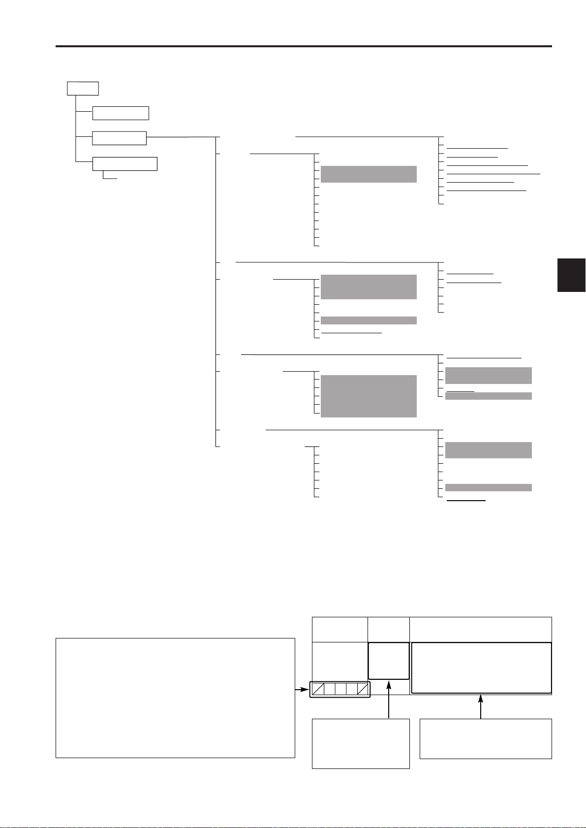
7-1 Menu configuration
Items selected in <USER MENU SELECT>
7
How to open the menus
USER MENU:
Press MENU button to display.
MAIN MENU:
Hold down MENU button for 3
seconds or more to display.
OPTION MENU:
Press MENU button while
holding down LIGHT button to
display.
<Notes>
≥There is a total of 42 camera-related items on three pages (14 items per page) and 14 VTR-related items on one page
which can be set.
≥The items with the shading cannot be selected using <USER MENU SELECT>.
≥The items with the underlining can be selected only using <USER MENU SELECT> on condition that all the items
(equivalent to the number of items on one page) are selected together. Individual items cannot be selected.
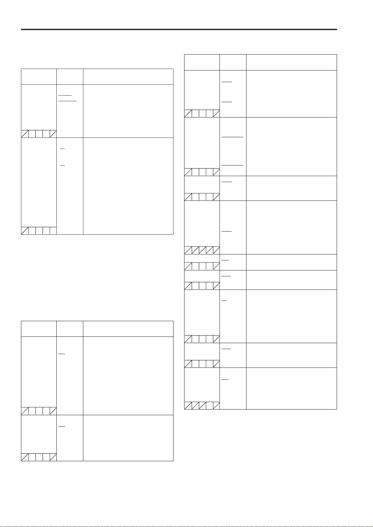
How to interpret the menu lists
The following abbreviations indicate whether the menu changes are stored
(written) in the corresponding data or loaded (read) from the data.
The changes cannot be stored or loaded when “/” is indicated.
S: The changes can be stored or loaded as scene file data.
C: The changes can be stored or loaded using CARD READ/WRITE.
U: The changes can be stored or loaded as user data.
Refer to sections “7-6-4 SCENE” and “7-6-5 INITIALIZE.”
F: The changes can be stored or loaded as READ FACTORY DATA.
Refer to section “7-6-5 INITIALIZE.”
R: The changes can be stored or loaded using RC DATA SAVE.
Refer to section “5-10 Connection of the remote control unit (AJRC10G).”
Item
SYSTEM MODE 1080-50i
This column indicates the
variable range in which the
item can be set and the
choice of the settings which
can be selected for the item.
Variable
range
1080-59.94i
720-50P
720-59.94P
For setting the system frequency and the
recording format of the unit.
When this item is switched, turn “OFF” the
POWER switch on the unit and then turn it
“ON” again.
Described in this column are the
operations which can be expected to
result when the item’s settings are
selected.
Remarks
101
Chapter 7 Menu description tables
CUF
CUFR
CUF
CUF
CUF
CUF
CUF
CUF
CUF
F
CUF
CUF
7-2 SYSTEM SETTING
(continued)
7-2-1 SYSTEM MODE
Item
SYSTEM MODE
For AJ-HDX900E
For AJ-HDX900P
CAMERA MODE
For AJ-HDX900E
For AJ-HDX900P
Variable
range
1080-50i
1080-59.94i
720-50P
720-59.94P
(1080-50i)
50i
25P
(1080-59.94i)
60i
30P
24P
24PA
(720-50P)
50P
25P
(720-59.94P)
60P
30P
24P
For setting the system frequency and the
recording format of the unit.
When this item is switched, turn “OFF” the
POWER switch on the unit and then turn it
“ON” again.
O When the remote control unit (AJ-RC10G)
is connected, this item is not displayed.
To switch this item, operate the main unit
independently.
For setting the video system for shooting.
<Note>
If the SYSTEM MODE item is changed while the time code is
advanced in the free-run mode (the TCG switch is set to the
F-RUN position.), the time code may not record properly.
When the SYTEM MODE item is changed and the power of
the unit is turned on again, check the time code and set it
again if necessary.
Remarks
7-2-2 REC FUNCTION
Item
INTERVAL REC
MODE
INTERVAL REC
HOLD
Variable
range
ON
ONE SHOT
OFF
ON
OFF
For setting the INTERVAL REC function.
ON:
For executing the interval recording.
It is possible to record in intervals in
increments of one frame.
ONE SHOT:
Recording is performed only once for the
time set in the REC TIME item, after
which it stops.
OFF:
Interval recording is not performed.
For details, refer to “3-5 Recording in
intervals (INTERVAL REC function).”
For setting whether the settings in the
INTERVAL REC MODE item are retained or
released, when the power is turned OFF.
ON: For retaining the settings in the
INTERVAL REC MODE item.
OFF: For releasing the settings in the
INTERVAL REC MODE item.
Remarks
Item
REC TIME
For 59.94 Hz
For 50 Hz
PAUSE TIME
For 59.94 Hz
For 50 Hz
TAKE TOTAL TIME NONE
TOTAL REC TIME 00m00s01f
AUDIO REC OFF
START DELAY 0SEC
PRE REC MODE OFF
PRE REC TIME 0SEC
RETAKE MODE ON
Variable
range
00s01f
:
59s29f
00s01f
:
59s24f
00h00m00s01f
:
00h04m59s29f
:
23h59m59s29f
00h00m00s01f
:
00h04m59s24f
:
23h59m59s24f
:
5day
:
99m59s29f
OVER
100min
NONE
ON
:
10SEC
ON
:
7SEC
OFF
Remarks
For setting the recording time (one cut).
When the CAMERA MODE item is set to
24P or 24PA, the value is set in increments
of 5 frames.
For setting the recording pause time.
When the CAMERA MODE item is set to
24P or 24PA, the value is set in increments
of 5 frames.
For setting the time required for shooting.
Select a setting from NONE (shooting
continues until it is stopped manually) to
5DAY (5 days).
For displaying the total recording time. The
setting for this time cannot be changed.
The total time yielded by adding the REC
TIME, PAUSE TIME and TOTAL TAKE
TIME is displayed.
O This indication is just a guide for the
recording time. It is impossible to record
for a period longer than the recording time
of the tape.
For setting the availability of audio records
during INTERVAL REC.
For setting the time taken until recording is
to start after the REC START button is
pressed in the INTERVAL REC mode.
For setting the PRE RECORDING function.
OFF: Recording starts about 0.4 seconds
after pressing the REC START button
or the VTR button on the lens.
ON: The PRE RECORDING function is
activated.
For details, refer to “3-4 To record video
signals of a few seconds before starting
recording (PRE-RECORDING function).”
For setting the length of time for which the
video and audio signals can be recorded
before the REC START button is pressed in
PRE RECORDING.
For setting the RETAKE function.
ON: The RETAKE function is activated.
OFF: The RETAKE function is not activated.
It returns to OFF once the power is turned
off.
For details, refer to “3-6 To take the previous
cut again (RETAKE function).”
The underlining in the variable range column indicates the setting in the preset
mode.
102
Chapter 7 Menu description tables
CUF
CUF
CUF
CUF
CUF
CUFR
CUFR
CUFR
CUFR
CUFR
CUFR
CUFR
CUFR
CUFR
CUFR
(continued)
7-2-3 OUTPUT SEL
Item
OUTPUT ITEM TC
MONI OUT HD-SDI
MONI OUT CHARA ON
MONI OUT MODE CAM
VF MODE CAM
Variable
range
STATUS
MENU
ONLY
HD-Y
OFF
VTR
VTR
Remarks
For setting the characters superimposed on
the output signals from the VIDEO OUT
connector.
TC:
Time codes are superimposed (when the
menu is accessed, the menu screen is
superimposed.)
STATUS:
The characters that are the same as the
characters superimposed in the
viewfinder screen are superimposed.
(When the menu is accessed, the menu
screen is superimposed.)
MENU ONLY:
The menu screen is superimposed only
when the menu is accessed. This
normally displays nothing.
For details, refer to “4-8-1 Settings of signals
output from VIDEO OUT connector.”
For setting video signals output from the
MON OUT connector.
HD-SDI:
For outputting the HD SDI signals
HD-Y:
For outputting the analog HD-Y signals
For details, refer to “4-8-2 Settings of signals
output from MON OUT connector.”
For superimposing characters on the HD
SDI output signals from the MON OUT
connector.
ON: To superimpose
OFF: Not to superimpose
<Note>
This does not link with the VIDEO OUT
CHARACTER switch.
For switching the signals output from the
MON OUT connector.
CAM: The camera images are output at all
times.
VTR: In the recording or other EE mode,
camera images are output from the
connector; in playback mode, the
VTR’s playback signals are output.
For switching the display mode of the
viewfinder screen.
CAM: The camera images are output at all
times.
VTR: In the recording or other EE mode,
camera images are displayed; in
playback mode, the VTR’s playback
images are displayed.
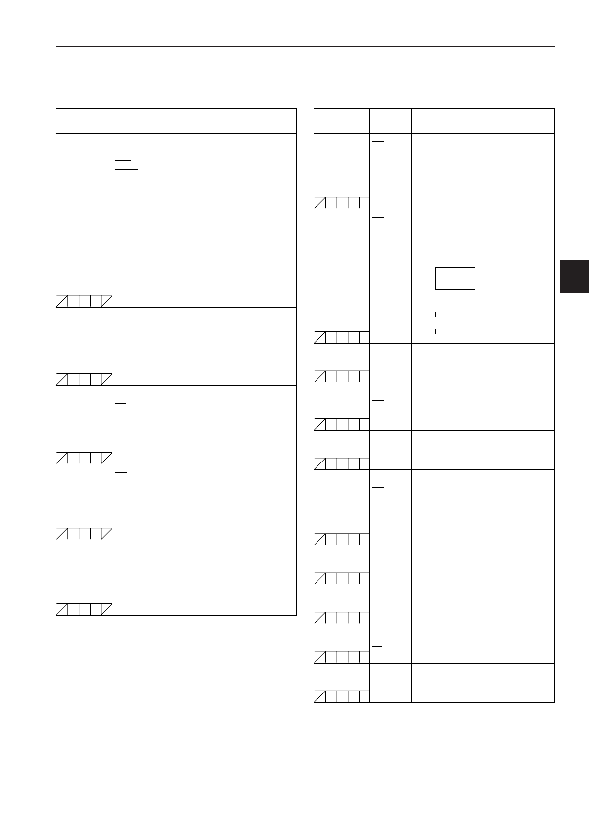
7-2-4 VIDEO OUT SETTING
Item
VIDEO OUT
CENTR MARK
VIDEO OUT
SAFETY MARK
SAFETY AREA 80%
VIDEO OUT FRM
MARK
FRM SIG 4:3
VIDEO OUT USER
BOX
USER BOX WIDTH 1
USER BOX
HEIGHT
USER BOX H POS –50
USER BOX V POS –50
Variable
range
OFF
1
2
3
4
OFF
1
2
:
90%
:
100%
ON
OFF
13:9
14:9
VISTA
ON
OFF
:
13
:
100
1
:
13
:
100
:
+00
:
+50
:
+00
:
+50
For setting the center marker to be
superimposed on the output signals of the
VIDEO OUT connector.
OFF: The center marker is not displayed.
1: + (large)
2: Center blank (large)
3: + (small)
4: Center blank (small)
For setting the type of safety marker frame
to be superimposed on the output signals of
the VIDEO OUT connector.
OFF: The safety marker frame is not
displayed.
1: Box
2: Corner frames
For setting the size of the safety marker.
It is possible to set the size by units of 1%
with a fixed ratio between of width and
height.
For superimposing the frame marker on the
output signals from the VIDEO OUT
connector.
ON: To superimpose
OFF: Not to superimpose
For setting the frame marker.
The VISTA setting is 16:8.65.
For superimposing the user box on the
output signals from the VIDEO OUT
connector.
ON: To superimpose
OFF: Not to superimpose
O It is not superimposed when the VIDEO
OUT switch is set to the SD-SDI or VBS
position.
For setting the horizontal width of the user
box.
For setting the vertical height of the user
box.
For setting the horizontal position of the user
box center.
For setting the vertical position of the user
box center.
Remarks
7
O The user box can be displayed in any position as a box-
type cursor.
O When the DOWNCON MODE item on the DOWNCON
SETTING screen is set to LT-BOX or S-CROP, the frame
marker and the safety marker are not displayed.
The underlining in the variable range column indicates the setting in the preset
mode.
103
Chapter 7 Menu description tables
CUFR
CUFR
CUFR
CUFR
CUFR
CUFR
CUFR
CUFR
CUFR
CUFR
CUFR
CUFR
CUFR
CUFR
CUFR
(continued)
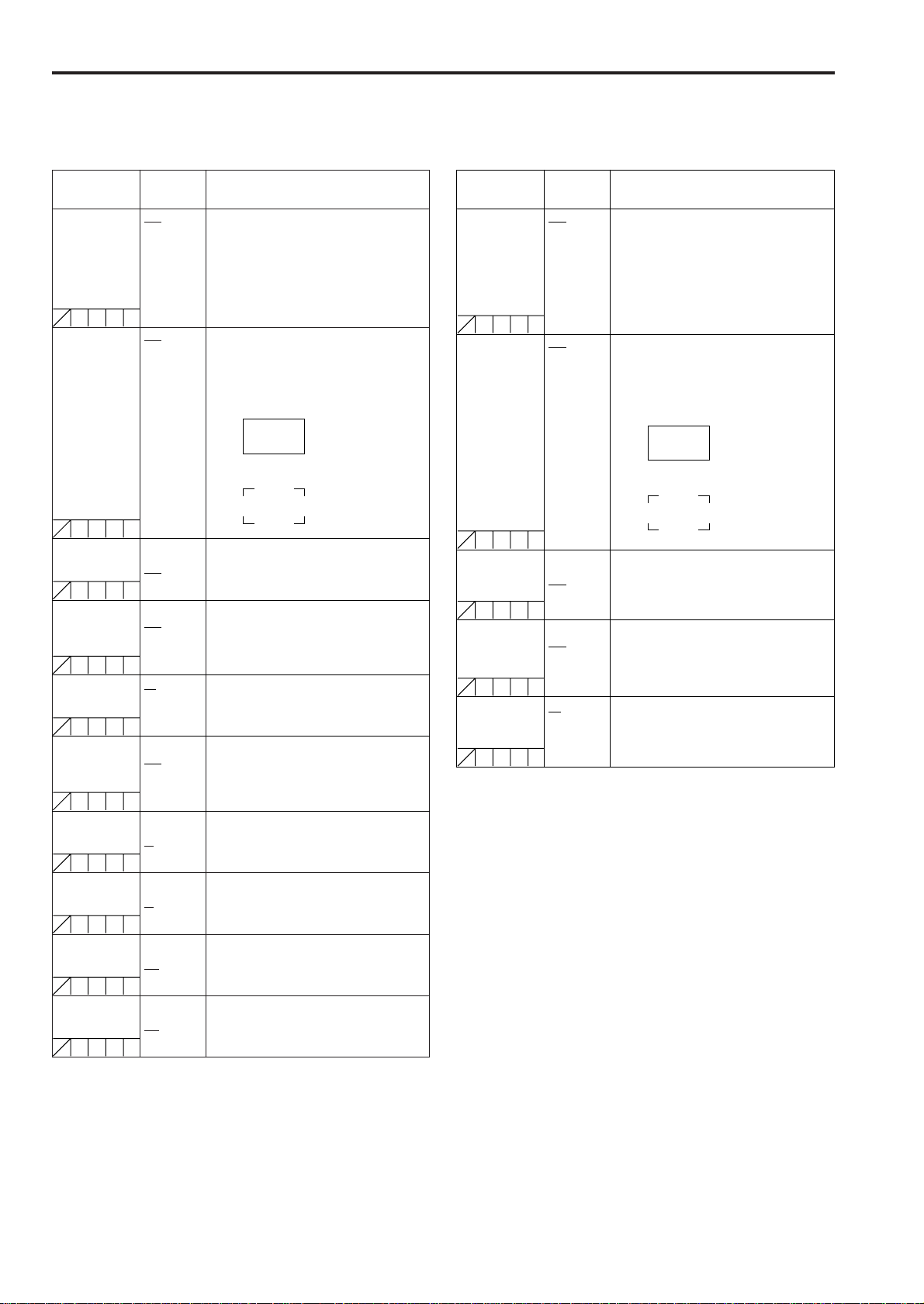
7-2-6 RC OUT SETTING7-2-5 MONITOR OUT SETTING
Item
MONI OUT CENTR
MARK
MONI OUT
SAFETY MARK
SAFETY AREA 80%
MONI OUT FRM
MARK
FRM SIG 4:3
MONI OUT USER
BOX
USER BOX WIDTH 1
USER BOX
HEIGHT
USER BOX H POS –50
USER BOX V POS –50
Variable
OFF
1
2
3
4
OFF
1
2
:
90%
:
100%
ON
OFF
13:9
14:9
VISTA
ON
OFF
:
13
:
100
1
:
13
:
100
:
+00
:
+50
:
+00
:
+50
range
Remarks
For setting the center marker to be
superimposed on the HD SDI output signals
of the MON OUT connector.
OFF: The center marker is not displayed.
1: + (large)
2: Center blank (large)
3: + (small)
4: Center blank (small)
For setting the type of the safety marker
frame to be superimposed on the HD SDI
output signals of the MON OUT connector.
OFF: The safety marker frame is not
displayed.
1: Box
2: Corner frames
For setting the size of the safety marker.
It is possible to set the size by units of 1%
with a fixed ratio between of width and
height.
For superimposing the frame marker on the
HD SDI output signals from the MON OUT
connector.
ON: To superimpose
OFF: Not to superimpose
For setting the frame marker.
The VISTA setting is 16:8.65.
For superimposing the user box on the HD
SDI output signals from the MON OUT
connector.
ON: To superimpose
OFF: Not to superimpose
For setting the horizontal width of the user
box.
For setting the vertical height of the user
box.
For setting the horizontal position of the user
box center.
For setting the vertical position of the user
box center.
Item
RC OUT CENTR
MARK
RC OUT SAFETY
MARK
SAFETY AREA 80%
RC OUT FRM
MARK
FRM SIG 4:3
Variable
OFF
1
2
3
4
OFF
1
2
:
90%
:
100%
ON
OFF
13:9
14:9
VISTA
range
For setting the center marker to be
superimposed on the output signals of the
REMOTE connector.
OFF: The center marker is not displayed.
1: + (large)
2: Center blank (large)
3: + (small)
4: Center blank (small)
For setting the type of the safety marker
frame to be superimposed on the output
signals of the REMOTE connector.
OFF: The safety marker frame is not
displayed.
1: Box
2: Corner frames
For setting the size of the safety marker.
It is possible to set the size by units of 1%
with a fixed ratio between of width and
height.
For superimposing the frame marker on the
output signals from the REMOTE connector.
ON: To superimpose
OFF: Not to superimpose
For setting the frame marker.
The VISTA setting is 16:8.65.
Remarks
<Notes>
O Settings in the SAFETY AERA item and the FRM SIG
item are interlinked with the respective connectors of
VIDEO OUT, MON OUT, and REMOTE.
O Settings in the respective items of USER BOX WIDTH,
USER BOX HEIGHT, USER BOX H POS, and USER
BOX V POS are interlinked with the VIDEO OUT
connector and the MON OUT connector.
O The user box can be displayed in any position as a box-
type cursor.
O When the DOWNCON MODE item on the DOWNCON
SETTING screen is set to LT-BOX or S-CROP, the frame
marker and the safety marker are not displayed.
The underlining in the variable range column indicates the setting in the preset
mode.
104
Chapter 7 Menu description tables
CUFR
CUFR
CUFR
CUFR
CUFR
CUFR
CUFR
CUFR
CUFR
CUFR
(continued)
7-2-7 DOWNCON SETTING
Item
DOWNCON MODE SQUEEZ
DETAIL ON
H.DTL LEVEL 00
V.DTL LEVEL 00
DTL CORING 00
H.DTL FREQ. 1
Variable
range
LT-BOX
S-CROP
OFF
:
08
:
31
:
04
:
31
01
:
15
:
3
:
5
For setting the mode of the down converter
output signals.
For setting the detail function for the down
converter output signals ON/OFF.
The down converter output signals contain
detailed components that are set during HD
signal processing. In this setting, these
signals overlap the detailed components
dedicated to the down converter outputs.
Even if this setting is turned off, it is
impossible to turn off the detailed
components set during HD signal
processing.
For setting the horizontal detail correction
level for the down converter output signals.
For setting the vertical detail correction level
for the down converter output signals.
For setting the noise elimination level of the
details.
For selecting the horizontal detail
frequencies.
1: 2.5 MHz 4: 4 MHz
2: 3 MHz 5: 4.5 MHz
3: 3.5 MHz
Remarks
7-2-8 GENLOCK
Item
GENLOCK INT
GL PHASE HD SDI
H PHASE COARSE –100
H PHASE FINE –100
Variable
range
EXT
COMPOSIT
:
+000
:
+100
:
+000
:
+100
Remarks
For setting the standard signals for
executing the GENLOCK.
INT: For synchronizing to the standard
signal within the unit regardless of the
signals that are input in the GENLOCK
IN connector.
EXT: For synchronizing to the standard
signals that are input in the GENLOCK
IN connector.
For selecting the output signals that lock
phases to the signals that are input in the
GENLOCK IN connector.
HD SDI:
For locking the HD SDI signals to the
GENLOCK input.
For the down converter output signals,
the start position of the video delays by
about 90 lines.
COMPOSIT:
For locking the down converter output
signals to the GENLOCK input.
For the HD SDI output signals, the start
position of the video gains by about 90
lines.
For making coarse adjustment for aligning
phases of the horizontal synchronization, for
executing the GENLOCK.
For making fine adjustment for aligning
phases of the horizontal synchronization, for
executing the GENLOCK.
7
2DLPF ON
SET UP
For AJ-HDX900E
For AJ-HDX900P
OFF
0%
7.5%
For setting the 2-D low path filter reducing
cross colors.
ON: Cross colors are reduced.
OFF: Cross colors are not reduced.
For setting the setup level for the down
converter output signals.
<Note>
When the system frequency is set to 50 Hz,
the setup level will be 0%.
The underlining in the variable range column indicates the setting in the preset
mode.
105
Chapter 7 Menu description tables
CUF
CUF
CUF
CUF
CUF
CUF
CUF
CUF
CUF
7-2-9 OPTION MODE
(continued)
Item
REC TALLY RED
P.OFF GPS DATA HOLD
1394 SPEED S200
1394 IN CH 0
Variable
range
GREEN
CHAR
CLEAR
S400
:
63
AUTO
Remarks
For selecting the method to access records
on the unit when the unit is connected to
peripheral devices and used remotely.
RED: The red tally lamp lights.
GREEN: The green tally lamp lights.
CHAR: For displaying “REC” in the
viewfinder.
For selecting whether or not to hold the
UMID GPS position information while the
power is off and record the information as
the data still held as the previous value until
another measurement can be taken after the
power is next turned on.
HOLD: The data is held and recorded.
CLEAR: The data is cleared at the same
time as the power is turned off, and
all zeros (no information) are
recorded from the time the power is
turned on until the measurement is
next taken.
For setting the transfer rate of signals output
from the DVCPRO connector.
S200: 200 Mbps
S400: 400 Mbps
For setting the input channel of signals input
to the DVCPRO connector.
0 – 63: To fix to the designated value
AUTO: To follow the settings of the
externally connected devices
1394 OUT CH 0
1394 CONTROL OFF
1394 CMD SEL REC_P
SDI METADATA ON
SDI EDH ON
:
63
AUTO
BOTH
STOP
OFF
OFF
For setting the input channel of signals
output from the DVCPRO connector.
0 – 63: To fix to the designated value
AUTO: To follow the settings of the
externally connected devices
For setting the control for recording
start/stop operations of external devices that
are connected to the DVCPRO connector.
OFF: Do not control the externally
connected devices.
BOTH: To control both the unit and the
externally connected devices
For setting the control of recording stop
operations of the external devices that are
connected to the DVCPRO connector.
REC_P: Operation to pause recording
STOP: Stopping operation
For setting metadata (UMID information) to
output to the HD SDI signals.
ON: To output
OFF: Not to output
For setting that the detection signals of the
communication error is output to the HD SDI
signals.
ON: To output
OFF: Not to output
The underlining in the variable range column indicates the setting in the preset
mode.
106
Chapter 7 Menu description tables
SCUFR
S UFR
SCUFR
SCUFR
SCUFR
SCUFR
SCUFR
SCUFR
SCUFR
SCUFR
SCUFR
SCUFR
SCUFR
SCUFR
SCUFR
SCUFR
7-3 PAINT
(continued)
7-3-1 RB GAIN CONTROL
Item
R GAIN AWB PRE –200
B GAIN AWB PRE –200
R GAIN AWB A –200
B GAIN AWB A –200
R GAIN AWB B –200
B GAIN AWB B –200
AWB A GAIN
OFFSET
AWB B GAIN
OFFSET
Variable
range
:
+000
:
+200
:
+000
:
+200
:
+000
:
+200
:
+000
:
+200
:
+000
:
+200
:
+000
:
+200
ON
OFF
ON
OFF
For setting the Rch gain when the WHITE
BAL switch is in the PRST position.
O If the remote control unit is connected,
settings made from the menu are
disabled. (The set value is displayed.)
For setting the Bch gain when the WHITE
BAL switch is in the PRST position.
O If the remote control unit is connected,
settings made from the menu are
disabled. (The set value is displayed.)
For setting the Rch gain when the WHITE
BAL switch is in the A position.
O If the remote control unit is connected,
settings made from the menu are
disabled. (The set value is displayed.)
For setting the Bch gain when the WHITE
BAL switch is in the A position.
O If the remote control unit is connected,
settings made from the menu are
disabled. (The set value is displayed.)
For setting the Rch gain when the WHITE
BAL switch is in the B position.
O If the remote control unit is connected,
settings made from the menu are
disabled. (The set value is displayed.)
For setting the Bch gain when the WHITE
BAL switch is in the B position.
O If the remote control unit is connected,
settings made from the menu are
disabled. (The set value is displayed.)
For setting the values of the Rch gain and
the Bch gain when the auto white balance is
executed as the WHITE BAL switch is in the
A position.
ON: To retain the values set in the items of
R GAIN AWB A and B GAIN AWB A
OFF: The values of the Rch gain and the
Bch gain is set to “0”.
For setting the values of the Rch gain and
the Bch gain when the auto white balance is
executed as the WHITE BAL switch is in the
B position.
ON: To retain the values set in the items of
R GAIN AWB B and B GAIN AWB B
OFF: The values of the Rch gain and the
Bch gain is set to “0”.
Remarks
7-3-2 RGB BLACK CONTROL
Item
MASTER PED –200
Variable
:
+015
:
+200
R PEDESTAL –100
:
+000
:
+100
G PEDESTAL –100
:
+000
:
+100
B PEDESTAL –100
:
+000
:
+100
PEDESTAL
OFFSET
R FLARE –100
ON
OFF
:
+000
:
+100
G FLARE –100
:
+000
:
+100
B FLARE –100
:
+000
:
+100
range
For setting the level of the master pedestal.
O If the remote control unit is connected,
settings made from the menu are
disabled. (The set value is displayed.)
For setting the pedestal level of the Rch.
O If the remote control unit is connected,
settings made from the menu are
disabled. (The set value is displayed.)
For setting the pedestal level of the Gch.
O If the remote control unit is connected,
settings made from the menu are
disabled. (The set value is displayed.)
For setting the pedestal level of the Bch.
O If the remote control unit is connected,
settings made from the menu are
disabled. (The set value is displayed.)
For setting the pedestal levels of the Rch,
the Gch and the Bch when the black balance
is adjusted.
ON: To retain the values set in the
respective items of R PEDESTAL, G
PEDESTAL, and B PEDESTAL
OFF: The pedestal levels of the Rch, the
Gch and the Bch are set to”0”.
For adjusting the flare level of the Rch.
Adjustment values in this item are added to
the flare adjustment value that is adjusted on
7-7-6 <LENS FILE ADJ> screen.
O If the remote control unit is connected,
settings made from the menu are
disabled. (The set value is displayed.)
For adjusting the flare level of the Gch.
Adjustment values in this item are added to
the flare adjustment value that is adjusted on
7-7-6 <LENS FILE ADJ> screen.
O If the remote control unit is connected,
settings made from the menu are
disabled. (The set value is displayed.)
For adjusting the flare level of the Bch.
Adjustment values in this item are added to
the flare adjustment value that is adjusted on
7-7-6 <LENS FILE ADJ> screen.
O If the remote control unit is connected,
settings made from the menu are
disabled. (The set value is displayed.)
Remarks
7
The underlining in the variable range column indicates the setting in the preset
mode.
107
Chapter 7 Menu description tables
SCUFR
SCUFR
SCUFR
SCUFR
SCUFR
SCUFR
SCUFR
SCUFR
SCUFR
SCUFR
SCUFR
SCUFR
SCUFR
SCUFR
SCUFR
SCUFR
SCUFR
SCUFR
SCUFR
SCUFR
SCUFR
SCUFR
(continued)
7-3-3 MATRIX
Item
∫ MATRIX TABLE
MATRIX R-G –63
Variable
range
A
B
:
+00
:
For selecting the color correction table for
the linear matrix.
For performing the linear matrix adjustment.
(red/green)
+63
MATRIX R-B –63
:
+00
:
For performing the linear matrix adjustment.
(red/blue)
+63
MATRIX G-R –63
:
+00
:
For performing the linear matrix adjustment.
(green/red)
+63
MATRIX G-B –63
:
+00
:
For performing the linear matrix adjustment.
(green/blue)
+63
MATRIX B-R –63
:
+00
:
For performing the linear matrix adjustment.
(blue/red)
+63
MATRIX B-G –63
:
+00
:
For performing the linear matrix adjustment.
(blue/green)
+63
∫ L MATRIX
TABLE
OFF
A
For selecting the color correction table when
the GAIN switch is in the L position.
B
∫ M MATRIX
TABLE
OFF
A
For selecting the color correction table when
the GAIN switch is in the M position.
B
∫ H MATRIX
TABLE
OFF
A
For selecting the color correction table when
the GAIN switch is in the H position.
B
<Note>
Items with $ in front of their names are set by the PAINT
MENU SW ($) R/W menu items on the <CARD R/W
SELECT> screen.
Items without $ in front of their names are set by the PAINT
MENU LEVEL R/W menu item.
For details, refer to “7-6-2 CARD R/W SELECT.”
Remarks
7-3-4 COLOR CORRECTION
Item
R (SAT)
R-Mg (SAT) –63
Mg (SAT) –63
Mg-B (SAT) –63
B (SAT) –63
B-Cy (SAT) –63
Cy (SAT) –63
Cy-G (SAT) –63
G (SAT) –63
G-Yl (SAT) –63
Yl (SAT) –63
Yl-R (SAT) –63
Variable
range
–63
:
+00
:
+63
:
+00
:
+63
:
+00
:
+63
:
+00
:
+63
:
+00
:
+63
:
+00
:
+63
:
+00
:
+63
:
+00
:
+63
:
+00
:
+63
:
+00
:
+63
:
+00
:
+63
:
+00
:
+63
For performing the color saturation
correction of red.
For performing the color saturation
correction between red and magenta.
For performing the color saturation
correction of magenta.
For performing the color saturation
correction between magenta and blue.
For performing the color saturation
correction of blue.
For performing the color saturation
correction between blue and cyan.
For performing the color saturation
correction of cyan.
For performing the color saturation
correction between cyan and green.
For performing the color saturation
correction of green.
For performing the color saturation
correction between green and yellow.
For performing the color saturation
correction of yellow.
For performing the color saturation
correction between yellow and red.
Remarks
The underlining in the variable range column indicates the setting in the preset
mode.
108
Chapter 7 Menu description tables
SCUFR
SCUFR
SCUFR
SCUFR
SCUFR
SCUFR
SCUFR
SCUFR
SCUFR
SCUFR
SCUFR
SCUFR
SCUFR
SCUFR
SCUFR
SCUFR
SCUFR
SCUFR
SCUFR
SCUFR
SCUFR
S UFR
SCUFR
(continued)
7-3-5 LOW SETTING
Item
R (PHASE)
–63
:
+00
:
+63
R-Mg (PHASE) –63
:
+00
:
+63
Mg (PHASE) –63
:
+00
:
+63
Mg-B (PHASE) –63
:
+00
:
+63
B (PHASE) –63
:
+00
:
+63
B-Cy (PHASE) –63
:
+00
:
+63
Cy (PHASE) –63
:
+00
:
+63
Cy-G (PHASE) –63
:
+00
:
+63
G (PHASE) –63
:
+00
:
+63
Variable
range
Remarks
For performing the hue correction for red.
For performing the hue correction between
red and magenta.
For performing the hue correction for
magenta.
For performing the hue correction between
magenta and blue.
For performing the hue correction for blue.
For performing the hue correction between
blue and cyan.
For performing the hue correction for cyan.
For performing the hue correction between
cyan and green.
For performing the hue correction for green.
Item
∫ MASTER GAIN
Variable
–3dB
:
0dB
:
30dB
H.DTL LEVEL 00
:
10
:
63
V.DTL LEVEL 00
:
20
:
31
DTL CORING 00
:
01
:
15
H.DTL FREQ. 00
:
18
:
31
LEVEL DEPEND. 0
1
:
5
MASTER GAMMA 0.30
:
0.45
:
0.75
BLACK GAMMA –3
:
OFF
:
+3
range
Remarks
For setting the master gain to –3, 0, 3, 6, 9,
12, 15, 18, 21, 24, 27 or 30 dB.
For performing the horizontal detail
correction level setting.
For performing the vertical detail correction
level setting.
For performing the noise elimination level
setting for detail.
For performing the horizontal detail
frequency selection.
For setting the LEVEL DEPEND.
When the Y-detail is emphasized, details of
dark sections are compressed.
If the numerical value is larger, details of
bright sections are also compressed.
For setting the master gamma.
(0.01 step)
For setting the gamma curve for the dark
portion.
–3 to –1:
The dark portion is compressed.
OFF:
Standard state
+1 to +3:
The dark portion is extended.
7
G-Yl (PHASE) –63
:
+00
:
For performing the hue correction between
green and yellow.
+63
Yl (PHASE) –63
:
+00
:
For performing the hue correction for yellow.
+63
Yl-R (PHASE) –63
:
+00
:
For performing the hue correction between
yellow and red.
+63
∫ COLOR
CORRECT
ON
OFF
For switching ON/OFF of the 12-axis
independent color correction of the position
selected with the GAIN switch (L, M, H).
The underlining in the variable range column indicates the setting in the preset
mode.
∫ MATRIX TABLE
OFF
A
For selecting the color correction table for
the linear matrix.
B
∫ COLOR
CORRECT
ON
OFF
For switching ON/OFF of the 12-axis
independent color correction.
<Note>
Items with $ in front of their names are set by the PAINT
MENU SW ($) R/W menu items on the <CARD R/W
SELECT> screen.
Items without $ in front of their names are set by the PAINT
MENU LEVEL R/W menu item.
For details, refer to “7-6-2 CARD R/W SELECT.”
109
 Loading...