

Panasonic AJ-HDX400E User Manual

Operating Instructions
Camera/VTR
Model No. AJ- E
Before operating this product, please read the instructions carefully and save this manual for future use.
F0205T0 -F
Printed in Japan
@
ENGLISH
VQT0P57
CAUTION:
TO REDUCE THE RISK OF FIRE OR SHOCK
HAZARD AND ANNOYING INTERFERENCE,
USE THE RECOMMENDED ACCESSORIES
ONLY.
CAUTION:
TO REDUCE THE RISK OF FIRE OR SHOCK
HAZARD, REFER MOUNTING OF OPTIONAL
INTERFACE BOARDS TO AUTHORIZED
SERVICE PERSONNEL.
DO NOT REMOVE PANEL COVERS BY
$
UNSCREWING THEM.
To reduce the risk of electric shock, do not remove the
covers. No user serviceable parts inside.
Refer servicing to qualified service personnel.
WARNING:
OTO REDUCE THE RISK OF FIRE OR SHOCK
HAZARD, DO NOT EXPOSE THIS EQUIPMENT TO
RAIN OR MOISTURE.
OTO REDUCE THE RISK OF FIRE OR SHOCK
HAZARD, KEEP THIS EQUIPMENT AWAY FROM
ALL LIQUIDS. USE AND STORE ONLY IN
LOCATIONS WHICH ARE NOT EXPOSED TO THE
RISK OF DRIPPING OR SPLASHING LIQUIDS,
AND DO NOT PLACE ANY LIQUID CONTAINERS
ON TOP OF THE EQUIPMENT.
Lithium Battery
Warning
The lithium battery in this equipment must only be
replaced by qualified personnel. When necessary,
contact your local Panasonic supplier.
“The lithium battery is a critical component (type
number CR2032 or BR2032 manufactured by
Panasonic.)
It must never be subjected to excessive heat or
discharge. It must therefore only be fitted in
equipment designed specifically for its use.
Replacement batteries must be of the same type
and manufacturer. They must be fitted in the same
manner and location as the original battery, with the
correct polarity connections observed.
Do not attempt to re-charge the old battery or re-use
it for any other purpose. It should be disposed of in
waste products destined for burial rather than
incineration.”
CAUTION
Danger of explosion if battery is incorrectly
replaced.
Replace only with the same or equivalent type
recommended by the equipment manufacturer.
Discard used batteries according to
manufacturer’s instructions.
VARNING
Explosionsfara vid felaktigt batteribyte. Använd
samma batterityp eller en ekvivalent typ som
rekommenderas av apparattillverkaren. Kassera
använt batteri enligt fabrikantens instruktion.
ADVARSEL!
Eksplosionsfare ved fejlagtig håndtering.
Udskiftning må kun ske med batteri af samme
fabrikat og type. Levér det brugte batteri tilbage til
leverandøren.
VAROITUS
Paristo voi räjähtää, jos se on virheellisesti
asennettu.
Vaihda paristo ainoastaan laitevalmistajan
suosittelemaan tyypiin. Hävitä käytetty paristo
valmistajan ohjeiden mukaisesti.
indicates safety information.
2
Attention/Attentie
Batteries are used for the main power source and memory back-up in the product.
O
At the end of their useful life, you should not throw them away.
Instead, hand them in as small chemical waste.
Voor de primaire voeding en het reservegeheugen van het apparaat wordt gebruikgemaakt van een
O
batterij.
Wanneer de batterij is uitgeput, mag u deze niet gewoon weggooien, maar dient u deze als klein
chemisch afval weg te doen.
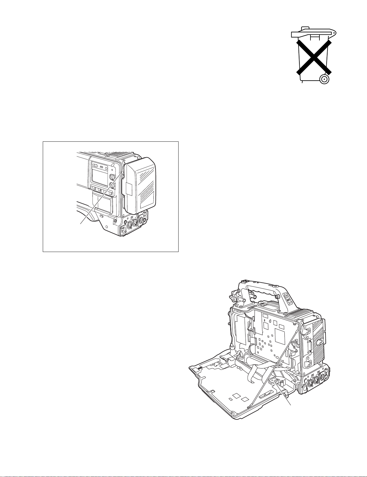
To remove the battery/Verwijderen van de batterij
Main Power Battery (Ni-Cd Battery)
Batterij Voor Primaire Voeding (Nikkelcadmiumbatterij)
Anton Bauer Battery
Anton Bauer-Batterij
If a battery made by any other manufacturer is to be used,
O
check the Operating Instructions accompanying the
battery.
In geval u een batterij van een anden fabrikant zou
O
gebruiken, gelieve dan eerst zorgvuldig de
gebruiksaanwijzing van deze batterij te lezen.
Unlock
Ontgrendelingshefboom
Back-up Battery (Lithium Battery)
Batterij Voor Reservegeheugen (Lithiumbatterij)
For the removal of the battery for disposal at the end
O
of its service life, please consult your dealer.
Raadpleeg uw leverancier over de verwijdering van de
O
batterij op het moment dat u het apparaat bij einde
levensduur afdankt.
Back-up Battery
(Lithium Battery)
Batterij Voor
Reservegeheugen
(Lithiumbatterij)
3

Contents
Chapter 1 General .................................... 6
1-1 Features of the camera unit ...................... 6
1-2 Features of the VTR unit ........................... 7
1-3 System configuration ................................ 8
Chapter 2 Parts and their functions ....... 9
2-1 Power supply and accessory
mounting section ....................................... 9
2-2 Audio function section ............................ 10
2-3 Shooting and recording/playback
function section ....................................... 12
2-4 Menu operation section ........................... 15
2-5 Time code related section ....................... 16
2-6 Warning/status display section .............. 17
2-7 Display window and its displays ............ 17
2-8 Viewfinder section ................................... 19
Chapter 3 Recording and playback ...... 20
3-1 Cassette tapes .......................................... 20
3-2 Basic procedures ..................................... 21
3-3 Scene-to-scene continuity ...................... 23
3-4 PRE-RECORDING function ...................... 23
3-5 INTERVAL REC function .......................... 24
3-6 RETAKE function ..................................... 25
3-7 Rec-review function ................................. 26
3-8 Normal playback and playback
at different speeds ................................... 26
Chapter 4 Adjustments and settings for
recording ............................... 27
4-1 Adjusting the white balance and
black balance ........................................... 27
4-1-1 Adjusting the white balance ......................... 27
4-1-2 Adjusting the black balance ......................... 29
4-2 Setting the electronic shutter ................. 30
4-2-1 Shutter modes ............................................. 30
4-2-2 Setting the shutter mode and speed ........... 30
4-2-3 Setting the synchro scan mode ................... 31
4-3 Selecting the recording signals and
recording system ..................................... 31
4-3-1 Selecting the record signals ........................ 31
4-4 Selecting the audio input signals and
adjusting their recording levels .............. 31
4-4-1 Selecting the audio input signals ................. 31
4-4-2 Adjusting the audio signal recording levels . 32
4-4-3 CH3 and CH4 recording levels .................... 32
4-5 Setting the time data ................................ 33
4-5-1 Setting the user bits ..................................... 33
4-5-2 Setting the internal clock’s date and time .... 34
4-5-3 Setting the time code ................................... 35
4-5-4 Externally locking the time code .................. 35
4-5-5 Setting the UMID information ...................... 36
4-6
Menu displays on the viewfinder screen
4-6-1 Menu configuration ...................................... 37
4-6-2 Basic menu operations ................................ 37
4-6-3 Selecting the user menus ............................ 38
....... 37
4-7 Viewfinder screen status displays ......... 39
4-7-1 Viewfinder lamp displays.............................. 39
4-7-2 Viewfinder screen status display
configuration..................................................39
4-7-3 Selecting the viewfinder screen display
items ............................................................ 39
4-7-4 Display modes and setting
changes/adjustment result messages ......... 45
4-7-5 Setting the marker displays ......................... 45
4-7-6 Setting the camera ID .................................. 45
4-7-7 Mode check screen displays
(MODE CHECK button function) ................. 46
4-7-8 Marker check screen displays
(MARKER SELECT button function) ........... 46
4-8 Menu-driven function setup .................... 47
4-8-1 Setting the USER SW GAIN switching ........ 47
4-8-2 Selecting the video output signals ............... 47
4-8-3 Selecting the F.AUDIO LEVEL
control function ............................................ 48
4-8-4 Allocating functions to the USER MAIN,
USER1 and USER2 buttons ........................ 48
4-8-5 Setting the color temperature manually ....... 49
4-9 Data handling ........................................... 49
4-9-1 Handling the setup card .............................. 49
4-9-2 Setup card operations ................................. 50
4-9-3 How to use the user data ............................ 53
4-9-4 How to use the scene file data .................... 54
4-9-5 How to return the menus settings to the
user standard settings ................................. 57
4-9-6 How to return the menus settings to the
factory standard settings ............................. 57
4-9-7 How to use the lens file data ....................... 57
Chapter 5 Preparation ........................... 58
5-1 Supplying the power ................................ 58
5-1-1 Attaching the battery and setting the
battery type .................................................. 58
5-1-2 Using an AC power supply .......................... 60
5-2 Attaching the lens and performing the
flange back and white shading
adjustments .............................................. 60
4

Contents
5-3 Audio input signal preparations ............. 65
5-3-1 When using the front microphone ............... 65
5-3-2 When using a wireless receiver ................... 65
5-3-3 When using an audio component ................ 66
5-4 Mounting the unit on a tripod ................. 66
5-5 Attaching the shoulder belt .................... 67
5-6 Adjusting the position
of the shoulder pad .................................. 67
5-7 Attaching the rain cover .......................... 67
5-8 Connecting the extension control unit
(AJ-EC3E) ................................................. 67
5-9 Attacching the FRONT AUDIO LEVEL
control knob ............................................. 68
Chapter 6 Maintenance and
inspections ........................... 69
6-1 Inspections prior to shooting ................. 69
6-1-1 Preparation for inspections .......................... 69
6-1-2 Inspecting the camera unit .......................... 69
6-1-3 Inspecting the VTR unit ............................... 70
6-1-4 Self-diagnosis function ................................ 71
6-2 Maintenance ............................................. 72
6-2-1 Condensation ............................................... 72
6-2-2 Head cleaning .............................................. 72
6-2-3 Cleaning inside the viewfinder ..................... 72
6-2-4 Phenomena inherent to CCD cameras ....... 72
6-2-5 Replacing the backup battery ...................... 72
6-2-6 Connectors and signals ............................... 73
6-3 Warning system ....................................... 74
6-3-1 Warning description tables .......................... 74
6-3-2 Error codes .................................................. 76
6-3-3 Emergency eject .......................................... 76
Chapter 7 Menu description tables ...... 77
7-1 Menu configfation .................................... 77
7-2 SYSTEM SETTING .................................... 78
7-2-1 SYSTEM SETTING ..................................... 78
7-2-2 REC FUNCTION ......................................... 78
7-2-3 OUTPUT SEL .............................................. 78
7-2-4 GENLOCK ................................................... 79
7-2-5 OPTION MODE ........................................... 79
7-3 PAINT ........................................................ 79
7-3-1 ROP ............................................................. 79
7-3-2 MATRIX ....................................................... 80
7-3-3 COLOR CORRECTION .............................. 80
7-3-4 LOW SETTING ............................................ 81
7-3-5 MID SETTING ............................................. 81
7-3-6 HIGH SETTING ........................................... 82
7-3-7 ADDTIONAL DTL ........................................ 82
7-3-8 SKIN TONE DTL ......................................... 83
7-3-9 KNEE/LEVEL .............................................. 83
7-3-10 GAMMA ....................................................... 84
7-3-11 FLARE ......................................................... 84
7-3-12 CAMERA SETTING .................................... 84
7-4 VF .............................................................. 85
7-4-1 VF DISPLAYS ............................................. 85
7-4-2 VF MARKER ............................................... 85
7-4-3 USER BOX .................................................. 86
7-4-4 VF INDICATOR1 ......................................... 86
7-4-5 VF INDICATOR2 ......................................... 86
7-4-6 MODE CHECK IND ..................................... 87
7-4-7 !LED ............................................................ 87
7-5 OPERATION .............................................. 87
7-5-1 CAMERA ID ................................................ 87
7-5-2 SHUTTER SPEED ...................................... 87
7-5-3 SHUTTER SELECT .................................... 88
7-5-4 USER SW .................................................... 88
7-5-5 SW MODE ................................................... 89
7-5-6 WHITE BALANCE MODE ........................... 90
7-5-7 USER SW GAIN .......................................... 90
7-5-8 IRIS ............................................................. 91
7-6 FILE ........................................................... 91
7-6-1 CARD READ/WRITE ................................... 91
7-6-2 CARD R/W SELECT ................................... 91
7-6-3 LENS FILE .................................................. 92
7-6-4 SCENE ........................................................ 92
7-6-5 INITIALIZE ................................................... 92
7-7 MAINTENANCE ........................................ 92
7-7-1 SYSTEM CHECK ........................................ 92
7-7-2 DIAGNOSTIC .............................................. 92
7-7-3 LENS ADJ ................................................... 92
7-7-4 BLACK SHADING ....................................... 93
7-7-5 WHITE SHADING ....................................... 93
7-8 VTR MENU ................................................ 93
7-8-1 VTR FUNCTION .......................................... 93
7-8-2 BATTERY/TYPE ......................................... 93
7-8-3 BATTERY SETTING1 ................................. 94
7-8-4 BATTERY SETTING2 ................................. 96
7-8-5 MIC/AUDIO1 ............................................... 97
7-8-6 MIC/AUDIO2 ............................................... 97
7-8-7 TC/UB .......................................................... 98
7-8-8 UMID SET/INFO .......................................... 98
7-8-9 VTR DIAG ................................................... 99
7-9 OPTION MENU........................................... 99
7-9-1 OPTION ....................................................... 99
7-9-2 DOWNCON SETTING ................................ 99
Chapter 8 Specifications ..................... 100
UniSlot is a trademark of Ikegami Tsusinki co., Ltd.
5

Chapter 1 General
The AJ-HDX400E is a video camera recorder that integrates a 3-CCD camera unit featuring a 2/3-inch on-chip lens that supports
progressive drive with a VTR unit that in turn supports the DVCPRO HD EX format.
One special feature of the camera unit is its ability to consistently express images with a high quality and high sensitivity since it
employs progressive drive.
The unit is both compact and lightweight, and it has a minimal power consumption. It features a high picture quality and
sensitivity, it has excellent mobility, and it effectively withstands dust, humidity and moisture. With all these features
incorporated, it can be used even for electronic news gathering activities.
Both the camera and VTR units employ digital signal processing technology to achieve even higher levels of picture quality and
stability and also to produce a system that enables the data to be controlled on the setup card.
1-1 Features of the camera unit
≥
E-cinema camera unit featured
This video camera recorder features the Varicam (AJHDC27F) camera unit that was developed for E-cinema
uses. This camera maximally exploits the excellence of
progressive scanning and, in delivering signals to the VTR
unit, it cross-converts the signals into the 1080i system
using a newly developed LSI chip.
≥ Progressive drive
The unit is a switchable progressive and interlaced
standards (1080/25P and 1080/50i) enable reader.
While progressive drive is used, the signals transferred to
and from the unit ae converted into interlace signais
(25PsF).
≥ Data control function
When the unit is used on its own, one set of user data and
four sets of scene file data can be registered. Further, by
using an SD card or a Multimedia Card (optional accessory)
as the setup card, up to eight sets of setup data can be
stored.
<Note>
SD card and MultiMedia card used in this unit do not
comply with the SD standard. Do not use cards formatted
using this unit with other camera-recorders. Further, NTFS
and FAT32 formatted cards cannot be used with this unit.
The recommended size for SD cards is 8 MB or more and 4
MB or more for MultiMedia cards.
≥ Storage type high-sensitivity function
The unit comes with a storage type gain increase function.
This is a function that makes it possible to achieve a higher
sensitivity of up to 20 dB above the regular gain increase.
≥ Digital zoom function
The unit is equipped with a digital zoom employing function.
This function is particularly useful when zooming further in
on a subject.
≥ 12-bit A/D conversion digital signal processing
circuitry
The analog images are processed into digital data by a 12bit A/D converter with sampling frequencies of 74 MHz, and
by operating the signal processor using the 74 MHz
frequency, it is possible to reproduce images which are
more finely detailed and achieve improvements in stability
and reliability.
≥
12-axis independent color correction function
Serving as a paint function, this facility enables the colors
for 12 axes to be compensated for independently and is
very useful for creating finely detailed images.
≥ MARKER SELECT button
At the front of the unit is a button for checking the
information concerning the markers on the viewfinder
screen. This is useful for checking the picture angle, for
instance, during shooting.
≥ ECU supported
The unit supports the AJ-EC3E extension control unit.
≥ Single-action shoulder pad slide function
It is now possible to adjust the position where the unit is
optimally balanced for operation using a single-touch action.
This means that the operator can easily optimize the unit’s
balance when the lens, battery and other peripheral camera
devices have been installed on the unit.
6

Chapter 1 General
1-2 Features of the VTR unit
≥
DVCPRO HD EX format system supported
The VTR unit employs the DVCPRO HD EX recording
format that supports the 1080i/25PsF,50i HD system. Using
the latest compression technology, it achieves two times the
economy of conventional DVCPRO HD format.
≥ Power-saving management function
In order to reduce its power consumption efficiently, the unit
has a function that shuts down circuitry that is not required
for the particular VTR mode established at the time. This
enables the user to perform operations while conserving
power.
≥ Pre-recording function featured
This function makes it possible to record the pictures and
sound up to 10 seconds ahead of the point in time when
recording is commenced by pressing the REC START
button or VTR button on the lens. It is effective in
preventing shots from being missed.
≥ Interval REC function provided
This unit is capable of interval shooting.
This unit makes it possible to conduct recording in intervals
with a minimum recording time in increments of one frame.
This is particularly useful for shooting science and nature
programs.
Furthermore, when the unit is used for one-shot recording,
frame-by-frame shooting is easily accomplished.
≥ RETAKE function
This function is for not leaving behind superfluous cuts
when a cut turns out to be no good during the shooting of
news, reports or art programmes. By cutting down on the
time taken for copying onto the work tape, for instance, this
function is very effective in achieving economical operation.
Users should remember to handle this function very
carefully.
≥ UniSlot wireless receiver
The unit’s construction supports a slot-in wireless receiver
which is available as an optional accessory.
≥ Built-in DOLBY NR system
The CUE audio recording circuitry contains a Dolby B noise
reduction circuit.
≥
Dolby noise reduction manufactured under license
from Dolby Laboratories Licensing Corporation.
≥
“DOLBY” and the double-D symbol Îare trademarks
of Dolby Laboratories Licensing Corporation.
≥ Frame-to-frame continuity
Simply by pressing the REC START button or VTR button
on the lens, the continuity from one frame to the next is
assured with a precision of +1 frame or less.
≥ Rec-review function
This automatically rewinds the tape for the last 2 to 10
seconds recorded and plays back the recording. This
enables the recording to be monitored easily.
≥ Built-in time code generator/reader
This enables the time code information to be recorded on
the dedicated sub-code track and played back.
≥ Metadata supported
The unit allows information from the AJ-GPS900G GPS unit
to be recorded on tape as the metadata UMID information.
This is useful when it comes to managing on-tape
information.
1
≥
SD down-converter output supported
This unit makes it possible to output SD down-converter
signals from its VIDEO OUT connector.
≥ Input signals of 4 separate audio channels
supported
The unit enables the audio input signals in four channels to
be selected separately. Further, the level of the signal in
each channel can be monitored on the LCD display window.
≥ Front audio level control
The unit’s front panel is equipped with a control for adjusting
the audio recording level. This is useful when the user is
filming on his or her own and the audio level needs to be
adjusted. It also is possible to cancel the effect of this control.
7

Chapter 1 General
1-3 System configuration
Microphone kit:
AJ-MC900G
Viewfinders:
AJ-HVF20B
(Mic holder provided)
Microphone holder:
AJ-MH800G
Lens
(Bayonet type):
Fujinon, Canon
GPS unit:
AJ-GPS900G
UniSlot wireless
microphone receiver:
Sennheiser EK3041
Video camera-recorder:
AJ-HDX400
Extension control unit:
AJ-EC3E
V-mount type battery plate
NP-1 type battery holder
BP-90 type battery holder
AC adapter:
AJ-B75
Battery
PRO14, TRIM14,
HYTRON50/100/120,
DIONIC90/160
ENDURA50/80, BP-L60/90
NP-L50
BP-H120, HP-90L
Rain cover:
SHAN-RC700
Soft carrying case:
AJ-SC900
(not available in some
area.)
Hard carrying case:
AJ-HT901G
Tripod adapter:
SHAN-TM700
SD memory cards
Multimedia cards
Cleaning tape:
AJ-CL12MP
M Cassette tapes:
AJ-HP33EMG
8
Chapter 2 Parts and their functions
2
1
34
6
5
7
8
9
:
;
<
=
>
6
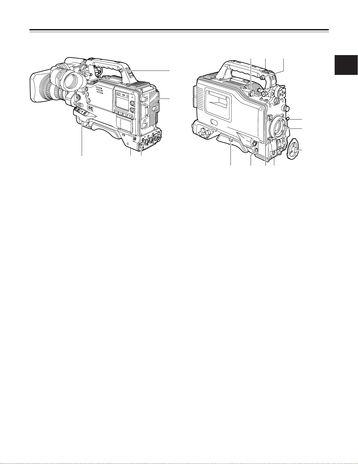
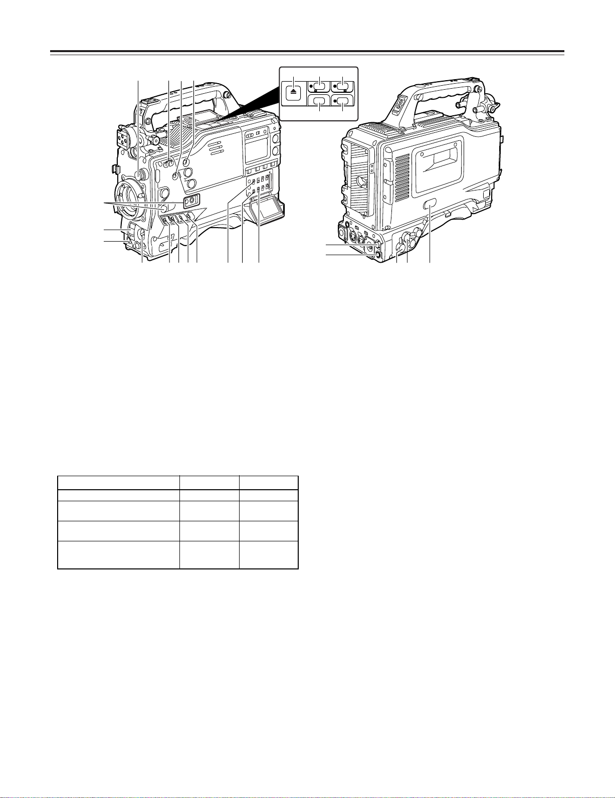
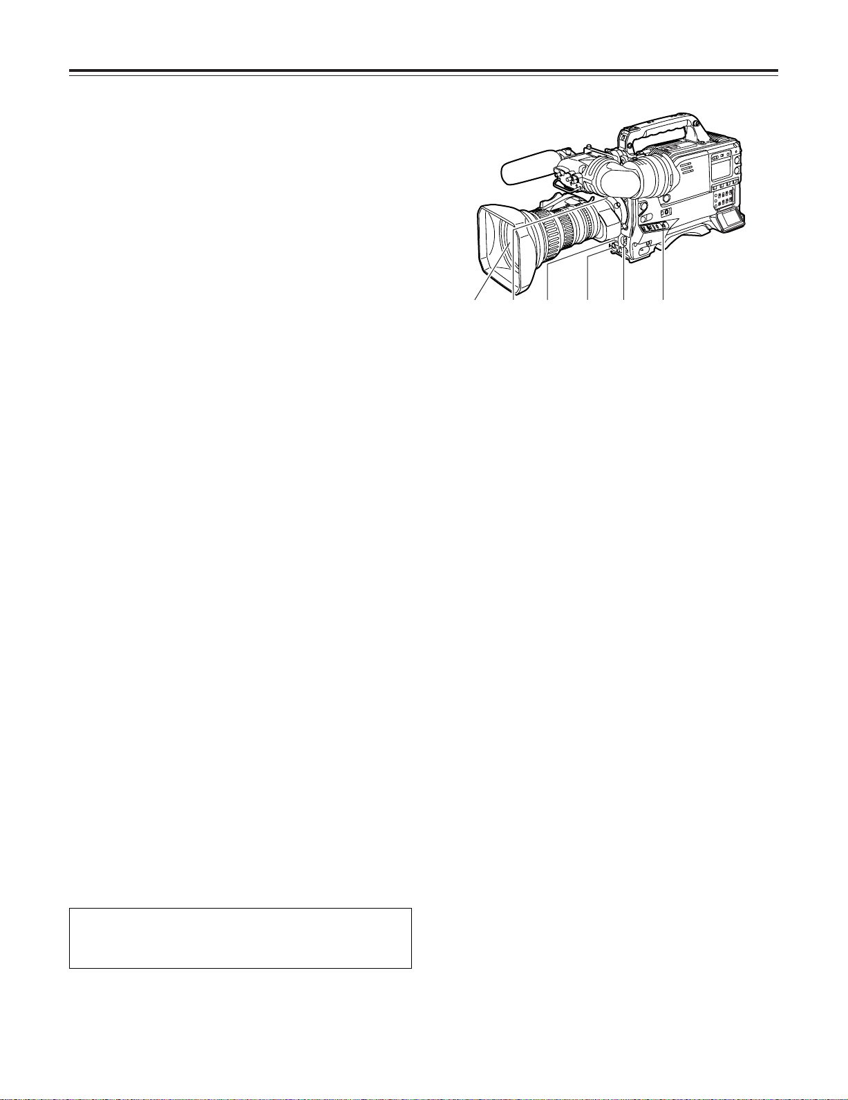
2-1 Power supply and accessory mounting section
2
1 POWER switch
This switch turns the power ON and OFF.
2 Battery mount
This is for attaching the Anton Bauer battery pack.
3 DC IN (external power input) socket (XLR, 4-pin)
When operating this unit using an AC power source, this
socket is connected to the model AJ-B75 AC adapter
(optional accessory).
4 BREAKER switch
If an excessively high current flows inside the unit due to
some problem or other, the circuit breaker is tripped and
the power is automatically turned off to protect the unit.
Push this button in after an inspection has been conducted
or repairs performed inside the unit by a qualified service
person. If there are no problems, the power will come back
on.
5 GPS connector
The connector from AJ-GPS900G, a GPS unit available as
an optional accessory, is connected here.
6 Shoulder belt fittings
The shoulder belt is attached here.
: Lens mount cap
To remove the cap, push the lens lever 9 up.
Keep the cap in place while the lens is not attached.
; Lens cable/microphone cable clamp
This clamp is for anchoring the lens cable or microphone
cable.
< Tripod mount
Mount the tripod adapter (SHAN-TM700), available as an
optional accessory, when the unit is to be anchored to a
tripod.
= LENS jack (12-pin)
The connecting cord of the lens is connected to this jack.
For further details on the lenses that can be used, refer to
the operating instructions of the lenses concerned.
> Easy-to-adjust shoulder pad
The position of the shoulder pad can be adjusted backward
or forward so that the unit is balanced when it is carried on
the user’s shoulder.
7 Light shoe
Use this to attach the video light, etc.
8 Lens mount (bayonet type)
The lens is attached to this mount.
9 Lens lever
This lever is tightened to secure the lens after it has been
attached to the lens mount.
9
Chapter 2 Parts and their functions
1
2
3
5
6
7
9
;
:
<
=
>
?
@
4
8
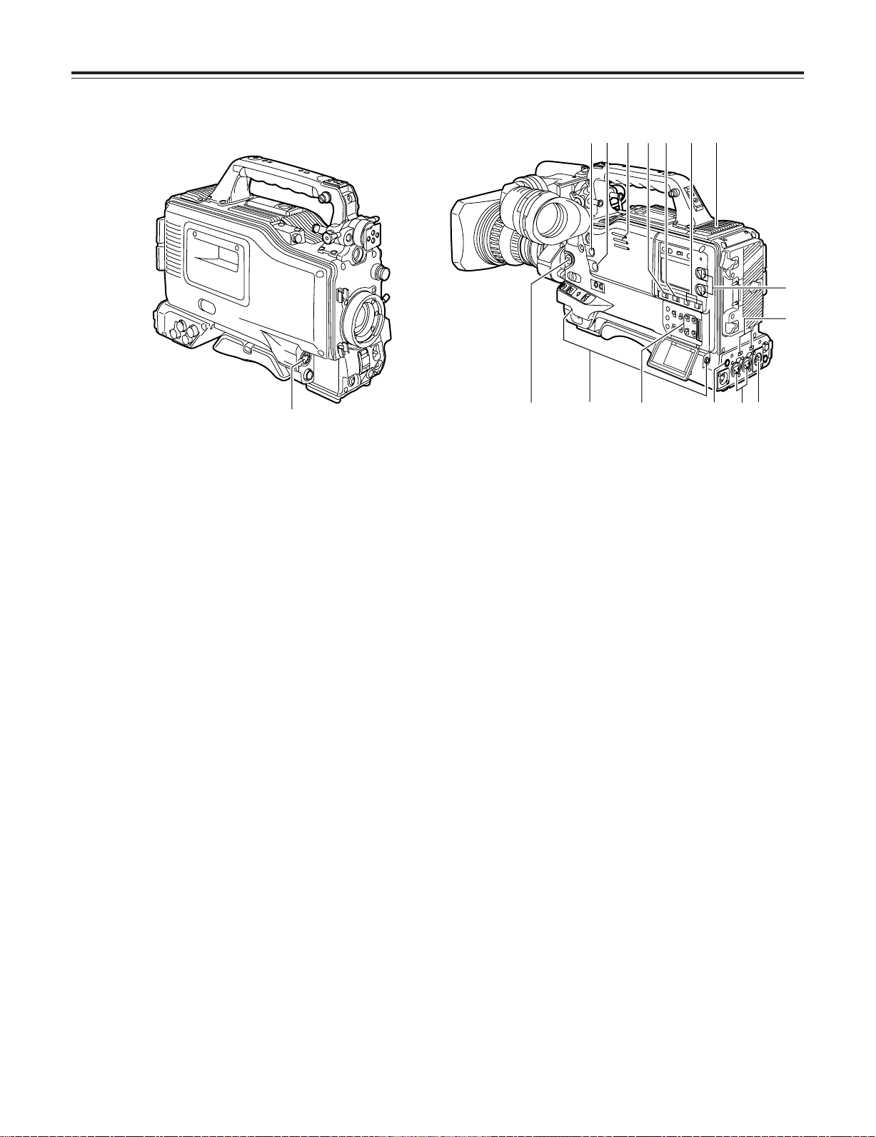
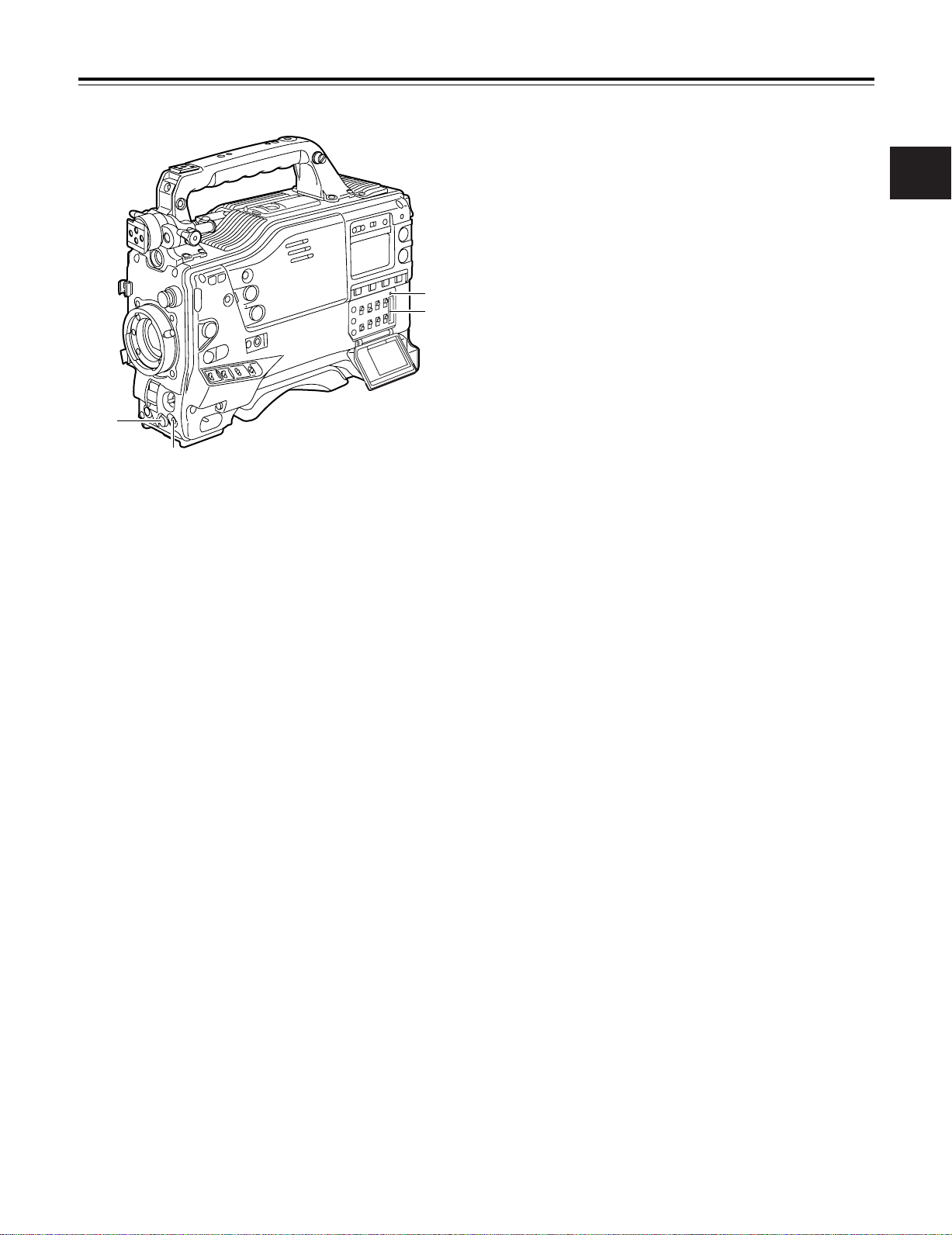
2-2 Audio function section (input system)
1 MIC IN (microphone input) jack (XLR, 5-pin)
Connect the microphone (optional accessory) here. The
power for the microphone is supplied from this jack.
2 AUDIO LEVEL CH1/CH2 (audio channel 1 & 2 recording
level adjustment) controls
When the AUDIO SELECT CH1/CH2 switch 3 is set to
MAN, the recording level of audio channels 1 and 2 can be
adjusted using these controls.
The controls come with a locking mechanism. Therefore, to
adjust the recording level, simultaneously push in and turn
the controls.
3 AUDIO SELECT CH1/CH2 (audio channel 1 & 2
automatic/manual level adjustment selector) switch
This is used to select the method for adjusting the
recording levels of audio channels 1 and 2.
AUTO : Set here for automatic adjustment.
MAN : Set here for manual adjustment.
4 AUDIO IN (audio input selector) switch
These are used to select the input signals to be recorded
on audio channels 1 and 2.
FRONT :
The input signals supplied from the microphone which
has been connected to the MIC IN jack 1 are recorded.
W.L. (wireless) :
The input signals from the slot-in wireless microphone
receiver are recorded.
REAR :
The audio input signals supplied from the audio
component which has been connected to the AUDIO IN
CH1/CH2 connectors 5 are recorded.
5 AUDIO IN CH1/CH2 (audio input channel 1 & 2)
connectors (XLR, 3-pin)
An audio component or microphones are connected here.
6 LINE/MIC/+48V (line input/mic input/mic input + 48V)
selector switch
This is used to switch the audio input signals from the
audio component which has been connected to the AUDIO
IN CH1/CH2 connectors 5.
LINE : The audio input signals from the audio component
serving as the line input are selected.
MIC : The audio input signals from the internal power
supply type of microphone are selected. (The
phantom mic power is not supplied from the unit.)
+48V : The audio input signals from the external power
supply type of microphone are selected. (The
phantom mic power is supplied from the unit.)
7 Wireless receiver slot
The UniSlot wireless receiver (optional accessory) can be
attached here.
8 FRONT AUDIO LEVEL (audio recording level
adjustment) control
This enables the recording level of audio channels 1 and 2
to be adjusted. This level can be adjusted regardless of
the setting position of the AUDIO SELECT switch.
When the <MIC/AUDIO1> screen is opened from the VTR
MENU page by performing a menu operation, whether to
enable or disable the operation of this level control can be
set using the FRONT VR CH1 and FRONT VR CH2 setting
items.
10

Chapter 2 Parts and their functions
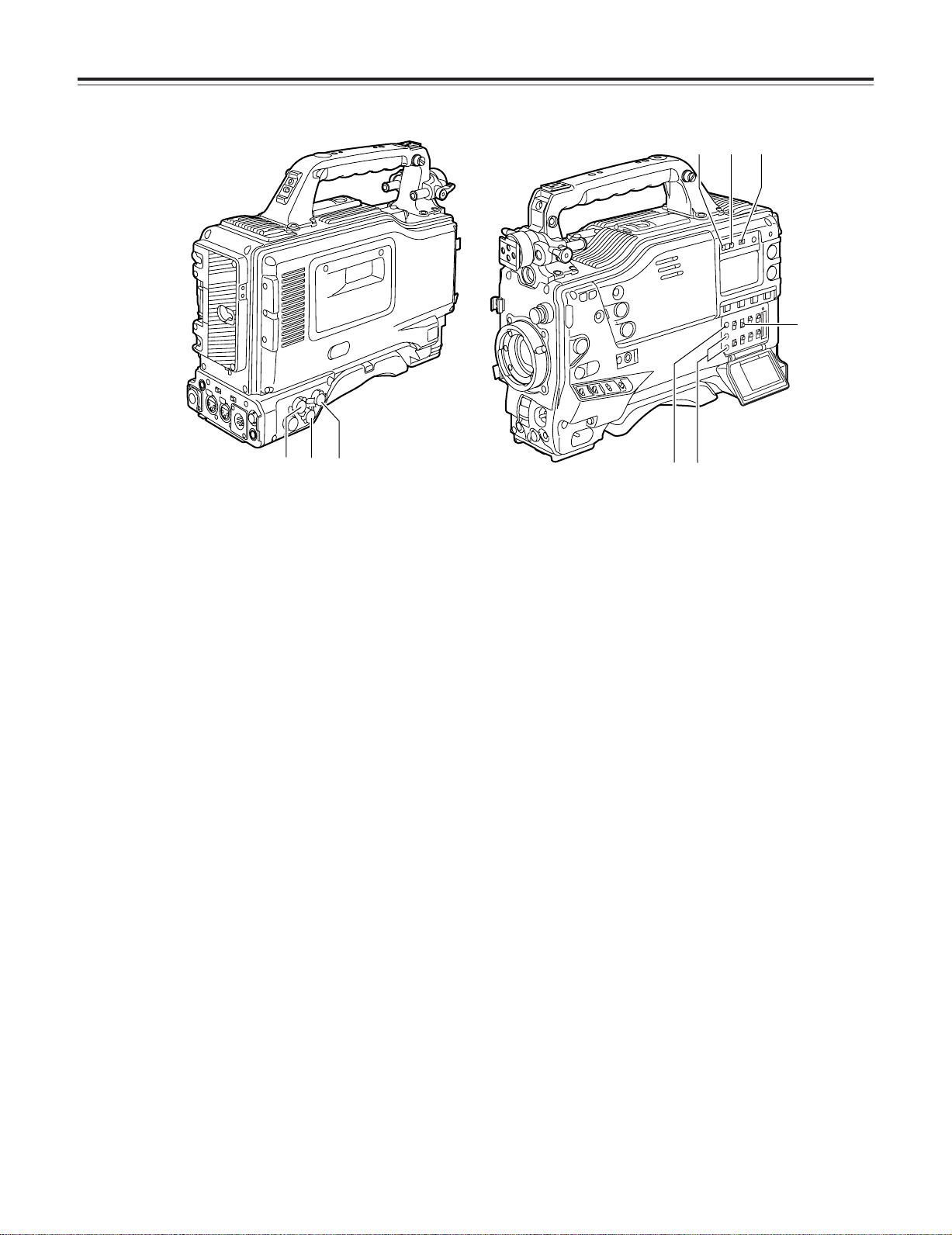
2-2 Audio function section (output system)
9 AUDIO OUT connector (XLR, 5-pin)
The audio signals recorded on audio channels 1 and 2 or
audio channels 3 and 4 are output from this connector.
The signals to be output can be selected using the
MONITOR SELECT CH1/2OCH3/4 selector switch :.
: MONITOR SELECT (audio channel) CH1/2OCH3/4
selector switch
This is used to select the audio channels whose signals are
to be output to the speaker, earphone and AUDIO OUT
connector.
CH1/2 : The signals of audio channels 1 and 2 are output.
CH3/4 : The signals of audio channels 3 and 4 are output.
In addition, the channel indications for the audio level
meters appearing in the display window and viewfinder
change when this switch is operated.
; MONITOR SELECT (audio selection)
CH1/3OSTOCH2/4 selector switch
This is linked with the MONITOR SELECT CH1/2OCH3/4
selector switch : and used to select the sound which is to
be output from the speaker, earphone and AUDIO OUT
connector.
CH1/3 : The signals of audio channel 1 or 3 are output.
ST : The stereo audio signals of either audio channels
1 and 2 or audio channels 3 and 4 are output.
Using a menu setting, the stereo signals can be
changed to MIX signals.
CH2/4 : The signals of audio channel 2 or 4 are output.
> Speaker
The EE sound during recording or the playback sound
during playback can be monitored through this speaker.
The warning alarms are output in synchronization with the
flashing or lighting of the warning lamps and warning
displays.
The sound heard from the speaker is automatically cut off
when earphones are connected to the PHONES jack ?.
? PHONES (earphones) jack (mini jack)
This is the earphone (stereo) jack which is used to monitor
the audio signals. When earphones are connected, the
sound from the speaker is automatically cut off. The sound
which is output from the two jacks (front and rear) is the
same.
<Note>
When listening to sound being recorded through speakers or
an earphone, there may be a slight time lag in the sound: this
is normal and not indicative of malfunctioning.
@ DC OUT (DC power supply) output socket
This normally serves as the DC 12 V output socket. A
current of approximately 1 A can be supplied.
2
MONITOR SELECT CH1/2OCH3/4 selector switch
CH1/2 CH3/4
CH1/3 Audio channel 1 Audio channel 3
ST
CH2/4 Audio channel 2 Audio channel 4
2 Either STEREO or MIX can be selected as the setting for the MONITOR
SELECT item by opening the <MIC/AUDIO2> screen from the VTR
MENU page by performing a menu operation.
< MONITOR (volume) control
This is used to adjust the volume of the monitor speaker or
earphone.
= ALARM (warning alarm volume adjustment)
This is used to adjust the volume of the warning alarms
from the earphones which have been connected to the
speaker > or PHONES jack ?.
The warning alarms are not audible when this control is at
its lowest setting.
Stereo2signals of audio
channels 1 and 2
Stereo2signals of audio
channels 3 and 4
11
Chapter 2 Parts and their functions
1
2
3
4
5
6
7
<
ª
6
5
1/;
EJECT
/
REW FF
/
STOP PLAY/PAUSE
B
C
;
=
>
A
I
D
G
H
E
F
@
:
8
9
?
2-3 Shooting and recording/
playback
function section
Shooting and recording (camera unit)
1 CC FILTER/ND FILTER (filter switching) controls
These are used to select the filter in accordance with the
subject’s brightness and color temperature.
CC FILTER knob (outside, large diameter)
A: Cross filter B: 3200 K
C: 4300 K D: 6300 K
ND FILTER knob (inside, small diameter)
1: CLEAR (transparent) 2: 1/4 ND
3: 1/16 ND 4: 1/64 ND
∫ Examples of filter selection
Shooting conditions
Sunrise, sunset, inside a studio B (3200 K)
Outdoors under a clear sky C (4300 K) or
Outdoors under cloudy or rainy
skies
Snowscapes, high mountains,
seashores or other perfectly clear
scenery
2 AUTO W/B (white/black) BAL switch
AWB : The white balance is automatically adjusted. When
the AWB memory selector switch on the side panel
is set to A or B and then the AUTO W/B BAL switch
is operated, the adjustment value is recorded in the
memory. When VAR has been selected as the
setting for AWB A and/or AWB B menus, the value
will be the one set in the menu and this switch will
not function. Note that this switch will also not
function at the PRST position.
ABB : The black balance is automatically adjusted.
If the AUTO W/B BAL switch is held down at the
ABB position for 5 or more seconds, the black
shading is compensated automatically.
CC filter
D (6300 K)
D (6300 K)
C (4300 K) or
D (6300 K)
1 (CLEAR)
2 (1/4 ND) or
3 (1/16 ND)
1 (CLEAR) or
2 (1/4 ND)
3 (1/16 ND) or
4 (1/64 ND)
ND filter
<Note>
When white balance or black balance are being
automatically adjusted and the switch is pressed again to
either the AWB side or to the ABB side, the automatic
adjustment for the side pressed will be stopped.
The adjusted value in this case is the value before
automatic adjustment was performed.
3 SHUTTER switch
This is the ON/OFF selector switch of the electronic
shutter.
OFF : The electronic shutter does not operate.
ON : The electronic shutter operates.
SEL : This is used when the electronic shutter speed is to
be changed.
The switch is a non-locking type. The shutter speed
changes each time it is operated. For further details, refer
to “4-2 Setting the electronic shutter.”
4 Synchro scan adjustment switches
These switches become effective when the shutter switch
3 is set to ON and SYNCHRO SCAN is selected. They
are used to adjust the synchro scan speed.
When the “–” switch is pressed, the shutter speed is
reduced; conversely, when the “+” switch is pressed, it is
increased.
During personal computer monitor shooting, etc. adjust
these switches to the positions where the horizontal bar
noise inside the viewfinder is decreased.
5 GAIN selector switch
This is used to select the gain of the video amplifier in
accordance with the lighting conditions prevailing at the
time of the shooting. The gain values for the L, M and H
settings are set ahead of time on the setting menu. Their
factory settings are 0 dB, 6 dB and 12 dB, respectively.
12

Chapter 2 Parts and their functions
6 OUTPUT/AUTO KNEE selector switch
This switch selects the video signals which are to be output
from the camera unit to the VTR unit, viewfinder and/or
video monitor.
CAM. AUTO KNEE ON:
The images shot by the camera are output. The AUTO
KNEE circuit operates.
CAM. AUTO KNEE OFF:
The images shot by the camera are output. The
MANUAL KNEE circuit operates.
BARS:
Color bar signals are output. The AUTO KNEE circuit
does not operate.
AUTO KNEE function
When shooting with the level set to people or scenes against a highbrightness background, the background will be whitened out, and the
buildings and scene in the background will be blurred. If the AUTO KNEE
function is activated at times like this, the background will be reproduced
clearly. This function is effective for shooting in the following situations:
≥ When shooting people in the shade under a clear sky
≥ When simultaneously shooting people in a car or indoors and the
outside scenery through a window
≥ When shooting scenes with a strong contrast
7 WHITE BAL (white balance memory selector) switch
This is used to select the method used to adjust the white
balance.
PRST:
Set the switch to this position at times when, for
instance, there is no time to adjust the white balance.
The factory setting for the white balance is 3200K, but
this can be changed to any other value by a menu
setting. For details, refer to “4-8-5 Setting the color
temperature manually.”
A or B:
When the AUTO W/B BAL switch 2 is set to AWB, the
white balance is automatically adjusted, and the
adjusted value is stored in memory A or memory B. For
details, refer to “4-1-1 Ajusting the white balance.”
As the factory setting, the settings are to be allocated to the
memory. Using a menu setting, it is also possible to allocate
the color temperatures of the user's choice to memory A and
memory B. For details, refer to “4-8-5 Setting the color
temperature manually.”
8 MODE CHECK button
Each time this button is pressed, one of the four screen
pages (STATUS screen display, !LED screen display,
FUNCTION screen display and AUDIO screen display) is
selected and displayed on the viewfinder to indicate the
camera’s settings.
This does not affect the output signals of the camera.
9 MARKER SELECT button
This is used to select the marker information displays on
the viewfinder screen. Each time it is pressed, the two
marker information display screens set by the menu are
switched in the following sequence: A (A marker display) 5
B (B marker display) 5 OFF (no marker display) 5 A, and
so on repeatedly. Note that when the power is switched
ON, the display on the viewfinder screen immediately
before the power was switched OFF will appear.
For details, refer to “4-7-8 Marker check screen displays.”
: USER MAIN, USER 1 and USER 2 buttons
A user setting can be allocated to each of these buttons
using the setting menu. When a button is pressed, the
user setting mode allocated to it is selected.
When the button is pressed again, the selected mode is
released.
For details, refer to “4-8-4 Allocating functions to the USER
MAIN, USER1 and USER2 buttons.”
Shooting and recording (VTR unit)
; REC START/STOP button
When this is pressed, recording starts; when it is pressed
again, recording stops. This button functions in the same
way as the lens VTR button.
< VTR SAVE/STBY (tape protection) switch
This is used to select the power supply mode when the
VTR has temporarily stopped recording (REC PAUSE
mode).
SAVE: This is the tape protection mode. The cylinder is
stopped in the half-loading status.
Less power is consumed than at the STBY
position, and the operating time provided by the
battery is prolonged. Compared with the STBY
position, it takes longer for recording to commence
after the REC START button ; has been pressed.
When the switch is set to this position, the VTR
SAVE lamp inside the viewfinder lights.
STBY : At this position, recording is commenced as soon
as the REC START button is pressed.
<Note>
When the prescribed amount of time has elapsed in the
STBY mode, the unit is automatically set to the SAVE
mode. To return the unit to the STBY mode, set the VTR
SAVE/STBY switch to SAVE, and then again to the STBY
position.
2
13

Chapter 2 Parts and their functions
= OUTPUT SEL (output signal selection) switch
This is used to select the signals output from the VIDEO
OUT connector and HD SDI connector.
VTR : In the recording or other EE mode, the camera
images are output from the connectors; in the
playback or other VV mode, it is the VTR’s playback
signals which are output.
CAM : The camera images are output at all times.
OFF : The video output is stopped and the power
reduction mode is established.
Furthermore, the audio output signals are synchronized
with the video signals as well.
For details on the video output, refer to “4-8-2 Selecting the
video output signals.”
<Note>
During recording, the output signals are not switched even
when the position of this switch is changed. They are
switched when the recording operation is stopped.
> CHARACTER switch
This is used to control the superimposing of the characters
onto the images which are output from the VIDEO OUT
connector and HD SDI connector.
ON : The characters are superimposed onto the images.
OFF : The characters are not superimposed onto the
images.
For details on the character types, refer to “4-8-2 Selecting
the video output signals.”
? DOWNCON switch
This is used to switch the mode of the SD down-converted
signals which are output from the VIDEO OUT connector.
LT BOX : Letter-box images are output.
SCROP : Images with their sides cropped are output.
SQUEEZE : Squeezed images are output.
@ VIDEO OUT (SD DOWNCON signal output) connector
This is the SD DOWNCON signal output connector. The
SD DOWNCON signals linked to the setting of the
OUTPUT SEL switch are output from here.
<Note>
Since this unit is an HD camera recorder, the color bars
which are output from the SD down-conversion output
connector are different from the SD standard color bars.
A ECU REMOTE (remote control) connector
The AJ-EC3E extension control unit (optional accessory) is
connected here.
C GENLOCK IN connector
The HD Y reference signal is supplied to this connector
when the camera unit is to be gen-locked or the time code
is to be externally locked.
PAL composite video signals may be input as the reference
signal instead but, in this case, the H phase cannot be
adjusted. Also, it is not possible to externally lock the sub
carrier of the unit’s down-converter output (composite video
signal).
D EJECT button
This is pressed to insert or eject the cassette.
E STOP button
This is pressed to stop the tape travel.
F PLAY/PAUSE button
This is pressed to view the playback picture on the
viewfinder screen or using a color video monitor. The
button’s lamp comes on during playback.
When it is pressed during playback, the unit is set to pause
in the playback mode (PLAY PAUSE), and the button’s
lamp flashes. If the unit is left in the pause mode for two
minutes, it automatically changes to the stop (STOP)
mode.
G REW (rewind) button and lamp
When this button is pressed during stop, the tape is
reviewed at high speed. Its lamp lights at this time.
When it is pressed during playback or pause, the tape is
reviewed at approximately 4 times the normal tape speed.
Both the PLAY lamp and REW lamp light at this time.
H FF (fast forward) button and lamp
When this button is pressed during stop, the tape is cued at
high speed. Its lamp lights at this time.
When it is pressed during playback or pause, the tape is
cued at approximately 4 times the normal tape speed.
Both the PLAY lamp and FF lamp light at this time.
I EMERGENCY screw (inside rubber cap)
If the cassette does not eject even when the EJECT button
is pressed, use a screwdriver or similar implement to push
and turn the EMERGENCY screw at the same time: this
will cause the cassette to be ejected.
For details, refer to “6-3-3 Emergency eject.”
B HD SDI (video and audio) connector
This is the connector for outputting the video signal which
is used for monitoring. The video signals linked to the
setting of the OUTPUT SEL switch are output from here.
Whether characters are to be superimposed onto the
images output from the VIDEO OUT connector can be
selected separately using the internal menu.
For details, refer to “4-8-2 Selecting the video output
signals.”
14
Chapter 2 Parts and their functions
4
3
2
1
2-4 Menu operation section
1 MENU button
This is used to switch the menu ON and OFF.
2
2 JOG dial button
This is used to select the menu items and perform settings
when the MENU button 1 is at the ON position.
3 Setup card insertion slot
This is where the SD card (optional accessory) or
Multimedia card (optional accessory) is inserted into the
unit.
4 BUSY (operation mode display) lamp
This lamp shows the operation mode of the setup card. It
lights during operation.
<Note>
When this lamp is lighted, refrain from inserting or
removing the card.
15
Chapter 2 Parts and their functions
1
2
3
9
8
7
4
6
5
2-5 Time code related section
1 GENLOCK IN connector (BNC)
The HD Y reference signal is supplied to this connector
when the camera unit is to be gen-locked or the time code
is to be externally locked. It is also possible to supply PAL
composite video signals instead as the reference signal.
2 TC IN connector (BNC)
Supply the time code which will serve as the reference to
this connector when externally locking the time code.
3 TC OUT connector (BNC)
To lock the time code of an external VTR to the unit’s time
code, connect this connector to the time code input (TC IN)
connector on the external VTR.
4 HOLD button
The time data display of the counter display section which
was on the screen at the moment when this button is
pressed is held. (However, the time code generator keeps
running.) When the button is pressed again, the hold
status is released.
It is used, for instance, to find out the time code or CTL
counter value at which a particular scene was shot.
5 RESET button
This is used to reset the time data on the counter display
section to “00:00:00:00.” If it is pressed while the TCG
switch 9 is at the SET position, the time code data and
user bits data are respectively reset to “00:00:00:00.”
7 “+” button, “–” button
These are used to increment or decrement by 1 the figure
in the digit which was made to flash by the SHIFT button 8
when the time code or user bits are to be set.
8 SHIFT button
This causes the digit to be set to flash when the time code
or user bits are to be set.
9 TCG (time code selector) switch
This is used to set the running mode of the built-in time
code generator.
F-RUN : Set here to have the time code run all the time
regardless of the VTR’s operation.
This position is used to align the time code with
the time or externally lock the time code.
SET : Set here when the time code or user bits are to be
set.
R-RUN : Set here to have the time code run only during
recording. The time code on the tape with sceneto-scene continuity is recorded continuously.
6 DISPLAY switch
This is used to display the time code, CTL or user bits on
the counter display section depending on the setting
positions of this switch and the TCG switch 9.
UB : The user bits are displayed.
TC : The time code is displayed.
CTL : CTL is displayed.
16
Chapter 2 Parts and their functions
5
1
2
4
3
6
CTL
RF
SE RVO
HUMID
SLACK
h
TAPE
EB
Y minM
s
frm
13 24
0
D
VTCG
TIME DATE
P-iREC
SLAVE HOLD GPS
BATT
EF
OVER OVER
10
OO
40
-dB
30
18
CTL
RF
SE RVO
HUMID
SLACK
h
TAPE
EB
Y minM
s
frm
13 24
0
D
VTCG
TIME DATE
P-iREC
SLAVE HOLD GPS
BATT
EF
OVER OVER
10
OO
40
-dB
30
18
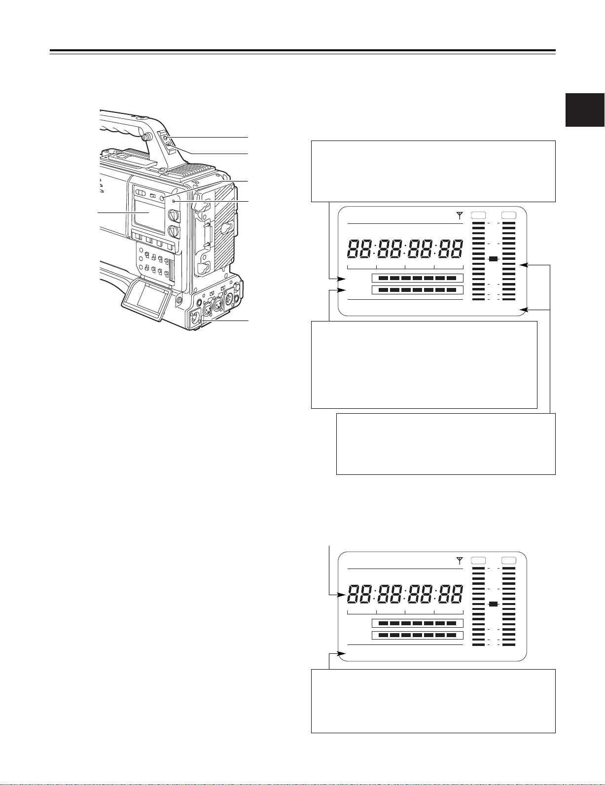
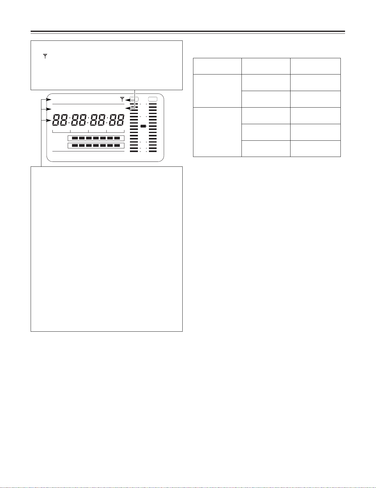
2-6 Warning/status display section 2-7 Display window and its displays
Remaining tape and remaining battery charge and
audio channel level displays
Remaining tape display
The remaining tape time is displayed using 7 segments.
The remaining tape time indicated by each segment is set to 3 minutes or 5
minutes using TAPE REMAIN/∫ on the VTR MENU “BATTERY/TAPE”
screen. Each time the number of minutes set for the segments elapses, one
segment is cleared.
2
1 Back tally lamp
When the back tally switch 2 is set to ON, this lamp
serves the same function as the front tally lamp in the
viewfinder.
2 Back tally switch
This is used to control the unit’s back tally lamp 1 and rear
tally lamp 6.
ON : The back tally lamp and rear tally lamp operate.
OFF : The back tally lamp and rear tally lamp do not
operate.
3 WARNING lamp
When a problem of some form or other occurs within the
VTR unit, this lamp flashes or lights.
4 LIGHT switch
This controls the lighting of the display window.
Each time it is pressed, the lighting of the display window
5 is set in turn from on to off or vice versa.
5 Display window
This displays the alarms, remaining battery charge, audio
levels, time data, etc. relating to the VTR unit.
Remaining battery charge display
If a battery with a digital display (% display) is used, all 7 segments up
to the “F” position light when the 70% or more of the battery charge
remains.
When there is less than 70% of the battery charge remaining, the
segments go out one by one in sequence every time the remaining
charge drops by 10%. It is also possible to set all 7 segments to light at
a 100% battery charge by selecting 100% as the setting for BATT
REMAIN FULL on the <BATTERY/TAPE> screen of the VTR menu.
Audio channel level meter
When the MONITOR SELECT CH1/2OCH3/4 switch is set to CH1/2,
numbers 1 and 2 indicating the audio channels appear, and the CH1
and CH2 audio levels are displayed. Conversely, when it is set to
CH3/4, numbers 3 and 4 indicating the audio channels appear, and
the CH3 and CH4 audio levels are displayed.
Displays relating to the VTR unit’s operations and
modes
Error code display
(for details, refer to “6-3 Warning system”)
6 Rear TALLY lamp
When the back tally switch 2 is set to ON, this lamp
operates in exactly the same way as the back tally lamp.
Warning displays
RF: Clogged video head
SERVO: Servo disturbance
HUMID: Formation of condensation on the head drum
SLACK: Problem in tape take-up
For details, refer to “6-3 Warning system.”
17
Chapter 2 Parts and their functions
CTL
RF
SE RVO
HUMID
SLACK
h
TAPE
EB
Y minM
s
frm
13 24
0
D
VTCG
TIME DATE
P-iREC
SLAVE HOLD GPS
BATT
EF
OVER OVER
10
OO
40
-dB
30
18
Mode displays
GPS: Lights when signals cannot be received during GPS operation.
GPS : Lights when signals are being received during GPS operation.
P-REC: Lights in pre-recording mode and flashes during the time set for
pre-recording after the tally lamp for recording has turned off.
iREC: Lights during recording when the interval recording mode is
established; flashes during recording standby.
i: Flashes when the interval recording mode has been selected.
Displays relating to the time code
SLAVE: Lights when the time code is locked externally.
HOLD: Lights when the time generator/reader value is being held.
CTL: Lights when CTL is selected by the DISPLAY switch and the
CTL count value is displayed.
TCG: Lights when TC (or UB) is selected by the DISPLAY switch and
the TC (or UB) generator value is displayed.
TC: Lights when TC (or UB) is selected by the DISPLAY switch and
the TC (or UB) reader value is displayed.
VTCG: Lights when UB is selected by the DISPLAY switch and the
VIUB generator value is displayed.
VTC: Lights when UB is selected by the DISPLAY switch and the
VIUB reader value is displayed.
TIME: Lights when UB is selected by the DISPLAY switch and the
values of the hour, minutes and seconds in real time are
displayed.
DATE: Lights when UB is selected by the DISPLAY switch and the
values of the year, month and day are displayed in real time.
No display: Remains off when UB is selected by the DISPLAY switch and
the real-time values of the hour and minutes in the time zone
are displayed.
Time counter display:
The time code, CTL, user bits and real time are displayed.
Time code-related switch settings and display items
TCG switch position
SET
F-RUN or R-RUN
DISPLAY switch
position
TC or CTL Time code
UB User bits
CTL CTL
TC Time code
UB User bits
Display item
<Note>
When UB has been selected by the DISPLAY switch, each time the HOLD
button is pressed, the setting is switched in the following sequence: VTCG
(VTC) 5 DATE 5 TIME 5 no display (time zone) 5 TCG (TC) and so on
repeatedly.
18
Chapter 2 Parts and their functions
ON
OFF
2
8
7;=
<
1
:
9
3645
>
?
@
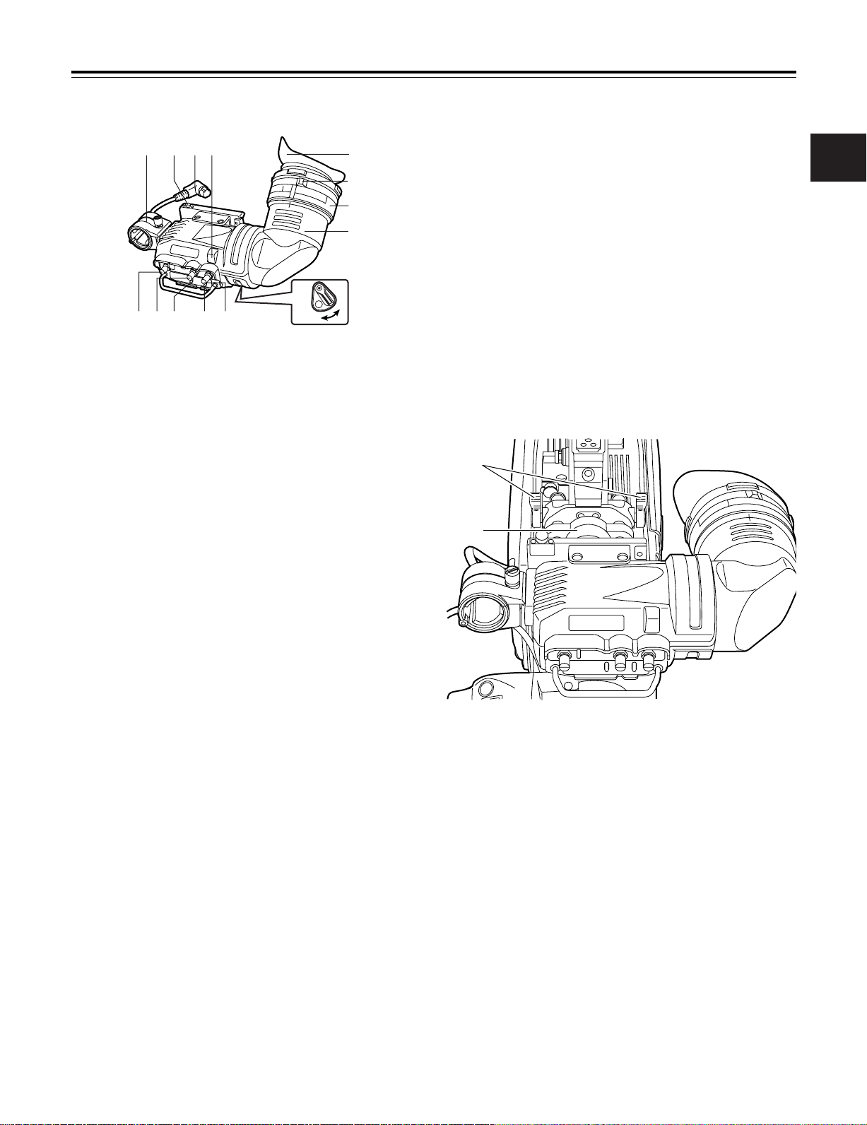
2-8 Viewfinder section
1 Viewfinder (optional accessory)
While recording or playback is underway, pictures can be
viewed through the viewfinder in black and white. The
warning displays concerning the unit’s operation statuses
and settings, messages, zebra patterns and markers
(safety zone markers and center marker) can also be seen
in the viewfinder.
2 ZEBRA (zebra pattern) switch
This is used to display the zebra pattern in the viewfinder.
ON : The zebra pattern is displayed.
OFF : The zebra pattern is not displayed.
8 Back tally lamp
This lamp lights while the VTR unit is recording. It also
flashes to provide a warning display like the REC lamp
inside the viewfinder.
When the lever is set to OFF, the back tally lamp is hidden.
9 Eyepiece
: Diopter adjustment ring
This is adjusted in line with the camera operator’s diopter in
such a way that the user can see the image on the
viewfinder screen most clearly.
; Connecting plug
< Locking ring
= Microphone holder
> Viewfinder stopper
This is used to attach and remove the viewfinder.
2
3 TALLY switch
This is used to control the front tally lamp 7.
HIGH: The brightness of the front tally lamp is increased.
OFF : The front tally lamp is turned off.
LOW : The brightness of the front tally lamp is reduced.
4 PEAKING control
This is used to adjust the outlines of the images seen
inside the viewfinder to make focusing easier. Its
adjustment does not affect the output signals of the
camera.
5 CONTRAST control
This is used to adjust the contrast of the picture seen inside
the viewfinder. Its adjustment does not affect the output
signals of the camera.
6 BRIGHT control
This is used to adjust the brightness of the picture seen
inside the viewfinder. Its adjustment does not affect the
output signals of the camera.
7 Front tally lamp
This lamp is activated when the TALLY switch 3 is set to
the HIGH or LOW position, and it lights while the VTR unit
is recording. It also flashes to provide a warning display
like the REC lamp inside the viewfinder. The lamp’s
brightness (HIGH or LOW) when it is lighted can be
selected using the TALLY switch.
? Viewfinder left-right position anchoring ring
This is used to adjust the left-right position of the
viewfinder.
@ Viewfinder front-back position anchoring ring
This is used to adjust the front-back position of the
viewfinder.
<Note>
For details, refer to “5-2 Attaching the viewfinder and
adjusting its position.”
19
Chapter 3 Recording and playback
REC
SAVE
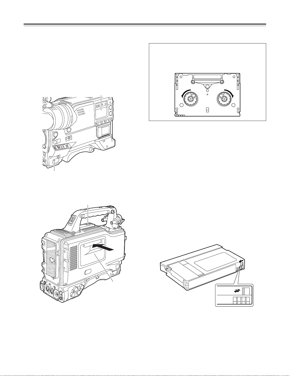
3-1 Cassette tapes
Loading a cassette tape
Set the POWER switch to ON.
1
<Note>
When condensation has formed inside the unit, the
HUMID display lights. Wait until this display is cleared
before proceeding with the intended operation.
HUMID display
POWER: ON
Press the EJECT button.
2
The cassette holder opens.
EJECT button
Checking for tape slack
Gently push in the reel using your finger and turn the reel in
the direction of the arrow. If the reel fails to turn, it means
there is no tape slack.
Ejecting the cassette tape
While the power is still on, press the EJECT button to open
the cassette holder, and take out the cassette tape. If another
cassette is not going to be loaded immediately after this tape
is ejected, close the cassette holder.
Ejecting the cassette when the battery has no
charge
First, set the POWER switch to OFF to turn off the unit’s
power.
Then turn the power back on, and immediately hold down the
EJECT button.
The cassette can be removed when there is still some power
left in the battery. However, do not repeat this operation.
Cassette holder
Insert the cassette tape and press the part marked with
3
the arrow to close the cassette holder securely.
<Note>
Check that there is no slack in the tape of the cassette.
20
To prevent accidental erasure
Set the cassette’s tab to SAVE to prevent the recordings on
the tape from being erased accidentally.
Chapter 3 Recording and playback
1
2
2
3
4
3-2 Basic procedures
This section describes the basic steps for shooting and
recording.
Before actually departing to shoot scenes, carry out
inspections to ensure that the system is functioning properly.
* For details on how to perform these inspections, refer to “6-1
Inspections prior to shooting.”
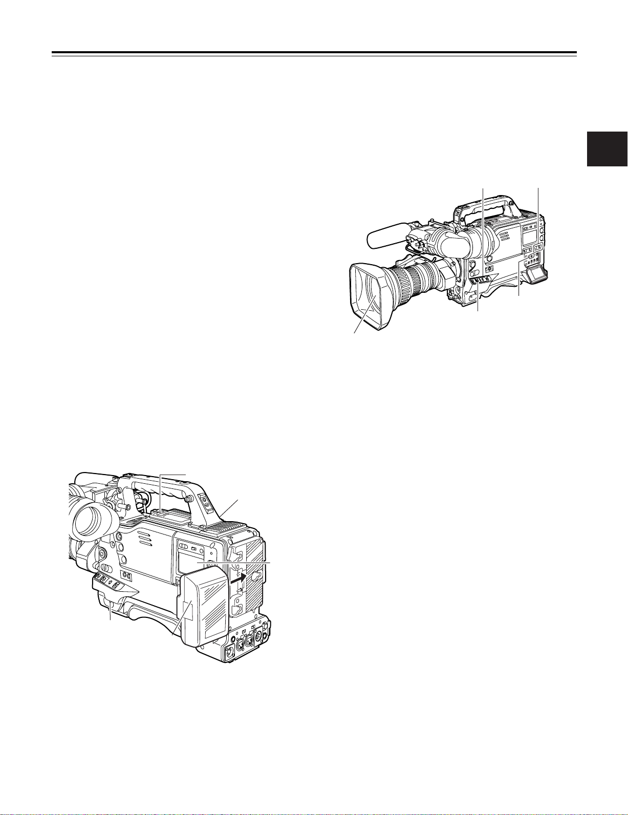
From providing the power supply to loading the
cassette
Attach a fully charged battery pack.
1
Set the POWER switch to ON. Now check that the
2
HUMID display is not showing and that at least 5
segments of the remaining battery charge display are
lighted.
≥If the HUMID display is showing, wait until it goes off.
≥When five or more segments of the remaining battery
charge display have not lighted, first check the battery
setting. If there is nothing wrong with the battery
setting, replace the existing battery pack with a fully
charged battery pack.
Check that there are no cables around the cassette
3
holder or top panel, and then press the EJECT button to
open the cassette holder.
Up to performing the switch settings
Provide the power supply, and load the cassette. Next, set
each switch as shown in the figure below, and then proceed
to operate.
Switch settings for shooting and recording
AUDIO SELECT
CH 1/CH 2:
AUTO
TCG:
F-RUN or R-RUN
Aperture:
Automatic
OUTPUT:
CAM/AUTO KNEE ON
GAIN:
Normally set to 0 dB; change to
a more suitable value if the
picture is too dark.
3
After checking the following points, insert the cassette
4
tape and close the cassette holder.
≥Position of the accidental erasure prevent tab
≥Tape slack
21
Chapter 3 Recording and playback
132-1, 2, 32-34 5, 6
Procedure for shooting
From adjusting the white balance and black balance
to stopping the recording
Select the filter to match the lighting conditions.
1
If the white balance has been stored in the memory
2-1
ahead of time:
Set the WHITE BAL switch to “A” or “B.”
If the white balance and/or black balance have not
2-2
been stored in the memory and there is no time to
adjust the white balance:
Set the WHITE BAL switch to PRST.
The white balance for the filter is achieved in
accordance with the setting position of the FILTER
control (outer).
When adjusting the white balance on the spot:
2-3
Select the filter to match the lighting conditions, set the
WHITE BAL switch to “A” or “B” and adjust the white
balance as follows:
1 Press the AUTO W/B BAL switch to the AWB
position and adjust the white balance.
2 Press the AUTO W/B BAL switch to the ABB
position and adjust the black balance.
3 Press the AUTO W/B BAL switch to the AWB
position and adjust the white balance again.
* For details on how to perform the adjustments, refer to “4-1-1
Adjusting the white balance” and “4-1-2 Adjusting the black
balance.”
From adjusting the white balance and black balance to stopping the recording
Point the camera at the subject, and adjust the focus and
3
zoom.
When the electronic shutter is to be used, set the shutter
4
speed and operating mode.
* For further details, refer to “4-2 Setting the electronic shutter.”
Press the REC START button or lens VTR button to start
5
recording.
During recording, the REC lamp inside the viewfinder
lights.
To stop the recording, press the REC START button
6
again.
The REC lamp inside the viewfinder goes off.
Tape function buttons
During recording, the tape function buttons (EJECT, REW,
FF, PLAY/PAUSE and STOP) will not work.
22
Chapter 3 Recording and playback
2
1
A
A
B
B
C
3-3
Scene-to-scene continuity
3-4
PRE-RECORDING function
Maintaining continuity from one scene to the next at an
accuracy of +1 frame or less can be assured simply by
pressing the REC START button or VTR button on the lens
while the unit is in the rec-pause mode.
If the unit is in a mode other than rec-pause, the point at
which the scene-to-scene continuity is to be maintained must
be located before recording is started.
Scene-to-scene continuity during rec-pause
The scene-to-scene continuity timing is located automatically.
However, the time taken until the start of recording differs
depending on the setting of the VTR SAVE/STBY switch.
≥ When the VTR SAVE/STBY switch is set to SAVE,
recording commences about two seconds after the REC
START button is pressed.
≥ When the VTR SAVE/STBY switch is set to STBY,
recording commences as soon as the REC START button
is pressed.
Ensuring scene-to-scene continuity after the power
was turned off while the unit was in the rec-pause
mode
Switch the power back on.
1
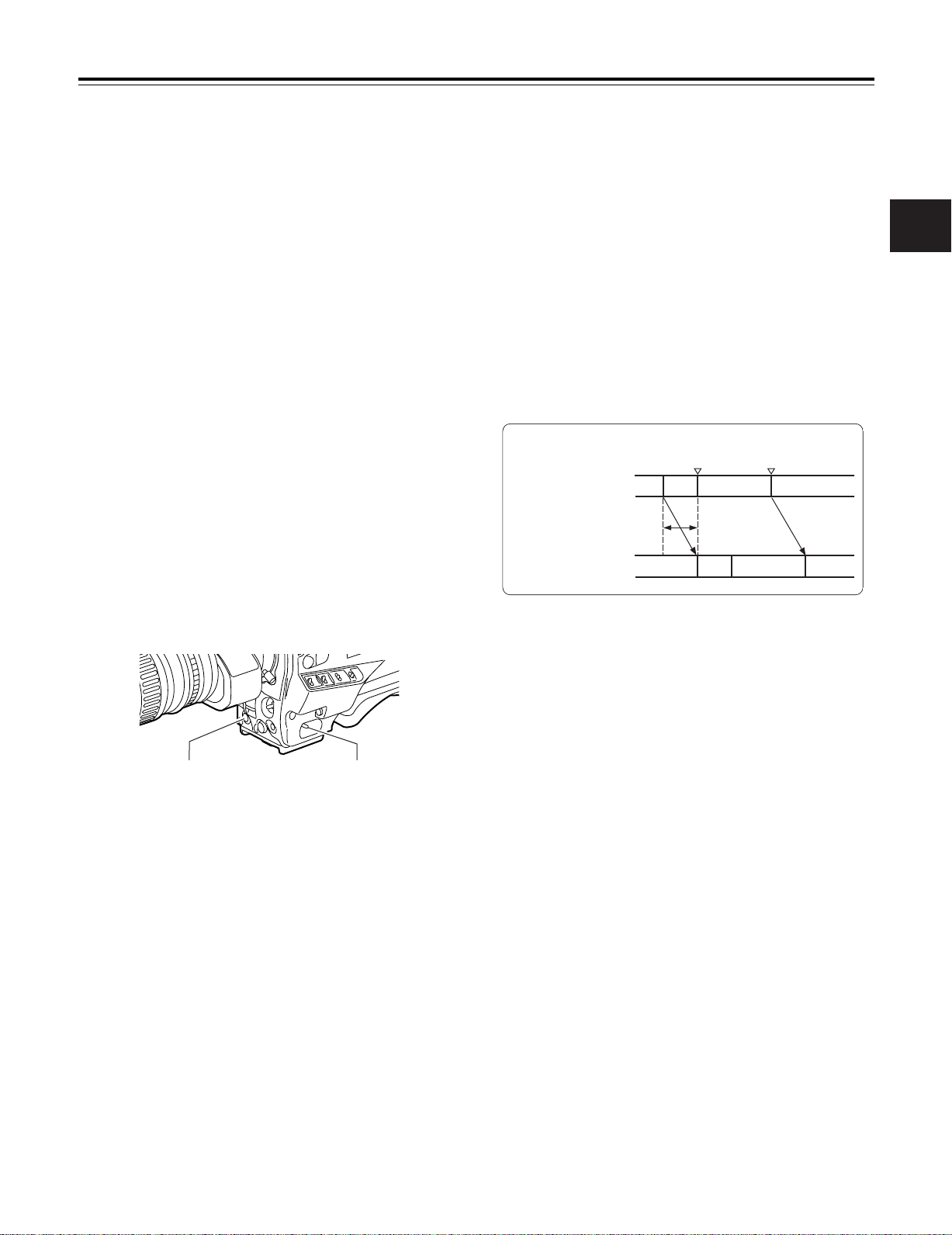
By always storing a few seconds’ worth (maximum of 10
seconds) of audio and video data shot by the camera, it is
possible to record video and audio signals a number of
seconds before recording is actually started by pressing the
REC START button or the VTR button on the lens.
In order for this function to be used, it is necessary to open
the <REC FUNCTION> screen from the SYSTEM SETTING
page and set the data storage time in the memory using the
PRE REC MODE item by performing menu operations.
The PRE REC MODE item settings are described below.
OFF: The PRE-RECORDING function is not activated.
0-10SEC: A value from 0 to 10 seconds is set as the length
of time for which the video and audio signals can
be recorded before the REC START button or VTR
button on the lens is pressed.
Real-time video signals
Real-time audio signals
PRE-REC time set
What is recorded on the
tape
REC start
(recording start)
Previous cut
REC pause
3
Press the REC START button or lens VTR button to start
2
the recording.
<Notes>
≥ The data contained in the storage memory becomes
unstable immediately after the power is turned on,
immediately after the PRE REC MODE item setting is
selected or its set time has been changed, and immediately
after playback or rec-review has been performed.
Immediately after any of these operations, therefore, the
video and audio signals will not be pre-recorded for the
duration set when recording is started by pressing the REC
START button or VTR button on the lens.
≥ The video data and audio data are not stored in the storage
memory while playback or rec-review is being performed.
This means that the pre-recording will not include the video
and audio signals supplied during a playback or rec-review
operation.
≥ Bear in mind that when the ZOOM UP function is activated
during the time set for pre-recording as a focus assist
function in the progressive mode, the zoomed-in image will
remain in the memory and end up being recorded on the
tape.
≥ When recording has been started, the time code (TCG)
display may remain in the hold status until it is possible for
the time code (TCR) on the tape to be read.
23
Chapter 3 Recording and playback
1
122
3
3
N
N
t1
t1
t2
t2
t1
t1
t2
t1
N-1
N-1
A
t
A
3-5 INTERVAL REC function
This unit enables recording in intervals with a minimum
recording time in increments of one frame to be conducted.
In order for this function to be used, it is necessary by
performing menu operations to open the <REC FUNCTION>
screen from the SYSTEM SETTING page, select the interval
recording mode using the INTERVAL REC MODE item, and
set the recording time (REC TIME), interval pause time
(PAUSE TIME) and time required for shooting (TOTAL TAKE
TIME). Upon completion of the settings, the total shooting
time (TOTAL REC TIME) is automatically calculated and
displayed.
The INTERVAL REC MODE item settings are described below.
OFF: Interval recording is not performed.
ON: Interval recording is performed.
ONE SHOT:
One-shot interval recording is performed for the time which
was selected by the REC TIME setting.
Procedure for shooting in the ON modes of
INTERVAL REC
After performing the basic operations for shooting and
1
recording as set forth in “3-2 Basic procedures,” secure
the unit in such a way that it will not move.
Press the unit’s REC START button or the VTR button on
2
the lens. Interval recording now starts. When the set
TOTAL TAKE TIME has elapsed, recording is ended
automatically.
As mentioned in “2-7 Display window and its displays,” “i”
flashes when the INTERVAL REC mode is selected. As
soon as recording starts, “iREC” lights. During rec-pause,
“iREC” flashes. Exactly what mode is established in the
unit can be ascertained by observing these displays.
The same displays as the ones in the display window also
appear inside the viewfinder, and the TALLY lamp lights
while recording is underway. Further, when the pause time
has been set to 2 minutes or more, the tally lamp blinks at 5
second intervals to inform the operator. Further, when
pause time has been set to 2 minutes or more, the tally lamp
blinks at 5 second intervals to indicate when recording is
paused. Under these conditions, the tally lamp will also flash
3 seconds before recording starts.
When recording is to be suspended at any time
Press the STOP button. Recording is now suspended.
O The tape may continue to run since the unit will record the
images stored in the memory until the moment when the
button is pressed.
When the recording is to be continued
Press the unit’s REC START button or VTR button on the lens
once more. Interval recording is now started again.
When the INTERVAL REC mode is to be exited
There are two ways to do this.
1) Set the unit’s POWER switch to OFF.
2) Perform a menu operation and select OFF as the
INTERVAL REC MODE item setting.
Procedure for shooting in the ONE SHOT mode
Follow the procedure below for shooting after the settings for
the interval recording mode have been completed.
After performing the basic operations for shooting and
1
recording as set forth in “3-2 Basic procedures,” secure
the unit in such a way that it will not move.
Press the unit’s REC START button or the VTR button on
2
the lens. When the set REC TIME has elapsed, the
recording is ended automatically.
As mentioned in “2-7 Display window and its displays,” “i”
flashes when the INTERVAL REC mode is selected. As
soon as recording starts, “iREC” lights.
When the recording ends, “iREC” flashes.
The same displays as the ones in the display window also
appear inside the viewfinder, and the TALLY lamp lights
while recording is underway.
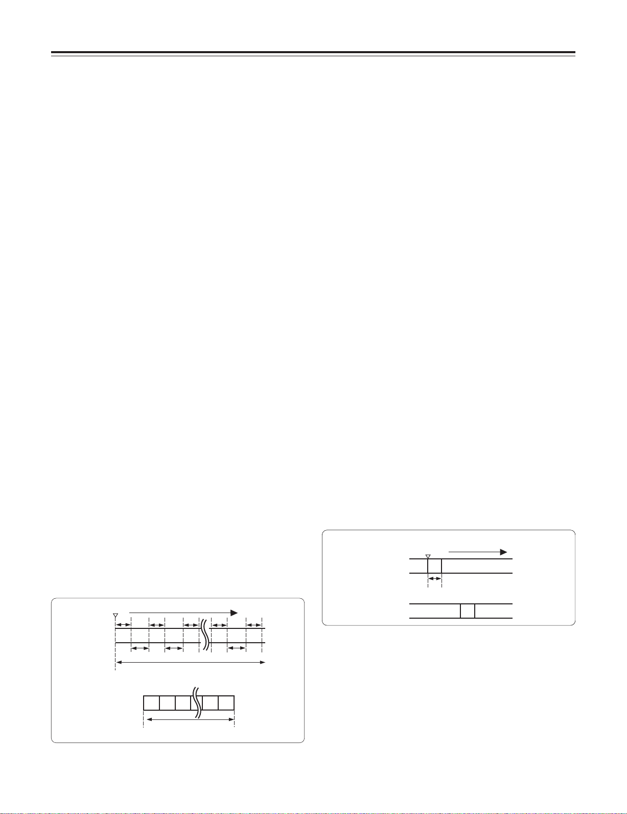
iREC
start
Real-time video signals
Real-time audio signals
Time base
REC TIME
(recording time = t1)
iREC start Time base
Real-time video signals
Real-time audio signals
TOTAL TAKE TIME
(time required for shooting)
What is recorded on the tape
24
(time during which signals are recorded on tape)
TOTAL REC TIME
REC TIME
(recording
time = t1)
PAUSE TIME
(pause time
= t2)
What is recorded on the tape Previous cut
Chapter 3 Recording and playback
When the recording is to be continued
Press the unit’s REC START button or VTR button on the lens
once more. One-shot recording is now started again.
When the ONE SHOT mode of INTERVAL REC is to
be exited
There are two ways to do this.
1) Set the unit’s POWER switch to OFF.
2) Perform a menu operation and select OFF as the
INTERVAL REC MODE item setting.
Checkpoints common to all INTERVAL REC modes
≥ Sound-related
Whether the sound is to be recorded or not during interval
recording is set by setting ON or OFF for the AUDIO REC
item on the <REC FUNCTION> screen.
≥ Tape function button-related
During interval recording, all the tape function buttons
(EJECT, REW, FF and PLAY/STILL) except STOP do not
work.
≥ The PRE RECORDING function does not work in the
INTERVAL REC mode.
≥ Starting recording quickly when unit is in pause mode
Selecting REC as the setting for one of either USER MAIN
or USER1/USER2 buttons in advance enables quick start
recording during pause mode when the set button is
pressed. Measurement of pause mode time is continued
even after quick start recording.
≥ When the unit’s power was turned off during recording
If the unit’s POWER switch was set to the OFF position
during interval recording with the use of the memory, the
tape will continue to run in order to record the video signals
which were stored in the memory until the moment when
the POWER switch was set to OFF, and then the power will
automatically go off.
If the battery was removed, the DC cable was disconnected
or the power supplied through the AC adapter was cut off
during recording, those shots (up to 5 seconds) taken prior
to the moment concerned may not be recorded. Bear this
in mind when the battery is to be replaced.
≥ When the tape has run out during recording
Bear in mind that if the tape has run out and stops during
interval recording with the use of the memory, those shots
(up to 5 seconds) taken prior to the moment when the tape
stopped may not be recorded.
≥ If a PLAY, FF or REW operation is performed after one-shot
recording, the operation will be performed after the images
remaining in the memory are written on the tape.
While the images are being recorded, the LED of the button
pressed (for play, FF or REW operation) will flash.
≥ Concerning the time code display
When recording has been started, the time code (TCG)
display may remain in the hold status until it is possible for
the time code (TCR) on the tape to be read.
≥ After turning the power ON, inserting a tape, or pressing
PLAY/FF/REW, the first recording made with INTERVAL
REC (including ONE SHOT mode) will be about 1 second
longer than the time set in the REC TIME menu option.
This is to guarantee the quality of consecutive recordings
and is not a defect.
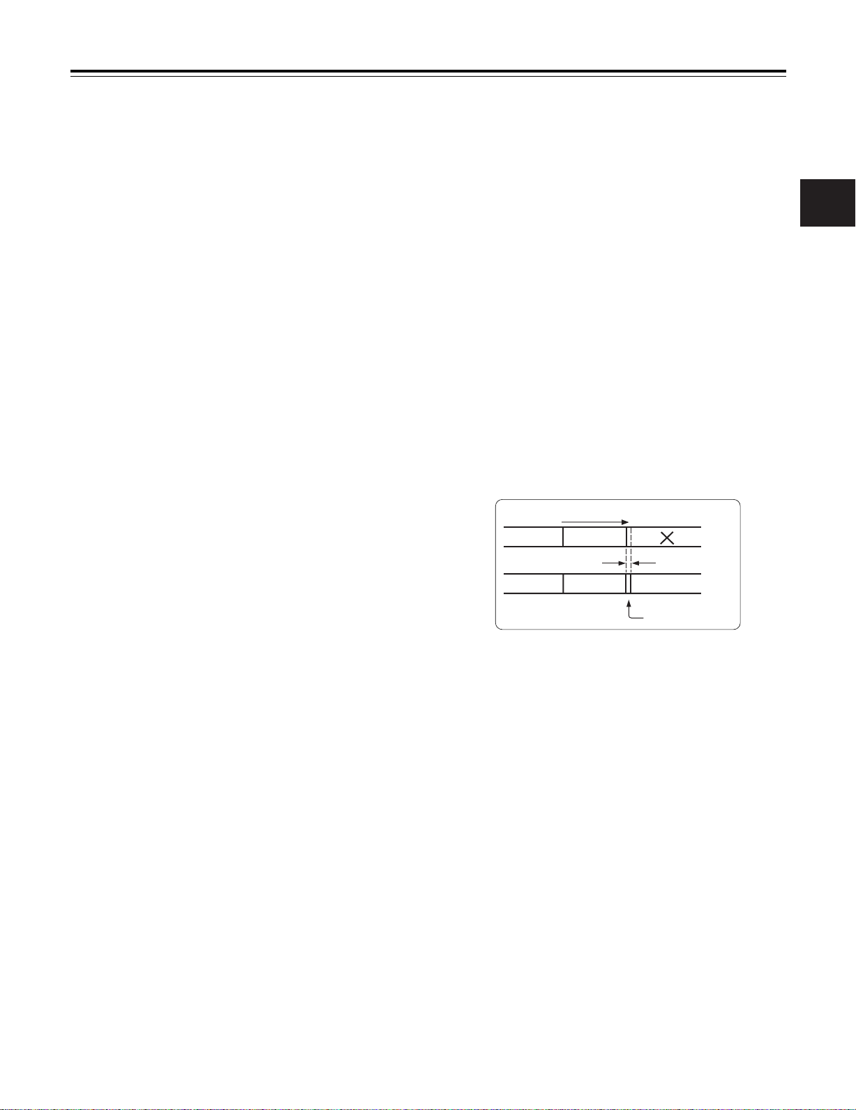
3-6 RETAKE function
The RETAKE function ensures continuity with the previous cut
on the tape when shooting is resumed.
It is set by opening the <REC FUNCTION> screen from the
SYSTEM SETTING page and selecting ON as the setting for
the RETAKE MODE item by performing menu operations.
The RETAKE MODE item settings are described below.
ON: The retake operation is performed when the RET button
on the lens is pressed while the MODE CHECK button
is held down.
OFF: The RETAKE function does not operate.
If, when the rec-pause mode is established upon completion
of the recording or the stop mode is established afterwards,
the RET button on the lens is pressed while the MODE
CHECK button is held down, the tape will be rewound to the
approximate start point (a position advanced by 10 or so
frames from the recording start) of the final image that was
last recorded, and the rec-pause mode will be established.
If there is some leeway in the shooting time and a “NG”
condition has been clearly identified, recording can be started
from this point, and the cut in the NG area will be deleted.
This function is particularly useful for cutting the amount of
time taken for copying onto work tapes and other such
economical operations.
Direction of tape travel
Cut 1 Cut 2
Cut 1 Cut 2
When the RETAKE function is to be exited
There are two ways to do this.
1) Set the unit’s POWER switch to OFF.
2) Perform a menu operation and select OFF as the
RETAKE MODE item setting.
Cut 3
Approx. 10 frames
Cut 4
Cut 3
25
3

Chapter 3 Recording and playback
3-7 Rec-review function
When recording is temporarily stopped and the lens RET
button is pressed, the last two seconds of the tape are
automatically rewound, and the playback pictures on this part
of the tape appear on the viewfinder screen. This makes it
possible to check whether recording was performed properly.
After the two seconds of the tape have been played back, the
unit is again set to the recording start standby mode.
If the RET button is held down, a maximum of 10 seconds of
the tape is rewound and played back.
The RET button function can be allocated by opening the
<USER SW> screen from the OPERATION page and
selecting settings for the USER MAIN SW, USER1 SW and
USER2 SW items by performing menu operations.
<Notes>
≥The rec-review function cannot be used unless recording
lasts for one or more seconds.
≥If the OUTPUT SEL switch on the side panel is at the VTR
position during the rec-review operation, the rec-review
images are output not only to the viewfinder but to the video
output connectors (VIDEO OUT connector and HD SDI
connector) as well. Bear in mind that if back-up images are
being recorded by a backup VTR that has been connected,
these rec-review images will end up being recorded.
Direction of tape travel
Recording section
2 to 10 sec.
Rec-review operation
Playback of recorded section
Rec-pause
No recorded or already recorded section
Rec-pause
3-8 Normal playback and playback at
different speeds
Black-and-white playback images can be viewed in the
viewfinder by pressing the PLAY button. When a color
monitor is connected to the unit’s VIDEO OUT connector and
an HD color video monitor is connected to its HD SDI
connector at the same time, the down-converted color
playback images from the VIDEO OUT connector can be
viewed on the color monitor while the HD high-quality images
from the HD SDI connector can be viewed on the HD color
video monitor.
≥In order to view these images, the OUTPUT SEL switch on
the side panel must be set to the VTR position.
In addition, when the FF and REW buttons are used, the
images can be played back at different speeds by establishing
the cue mode (PLAY + FF), review mode (PLAY + REW),
high-speed fast forward playback mode (FF) or high-speed
rewind playback mode (REW).
26
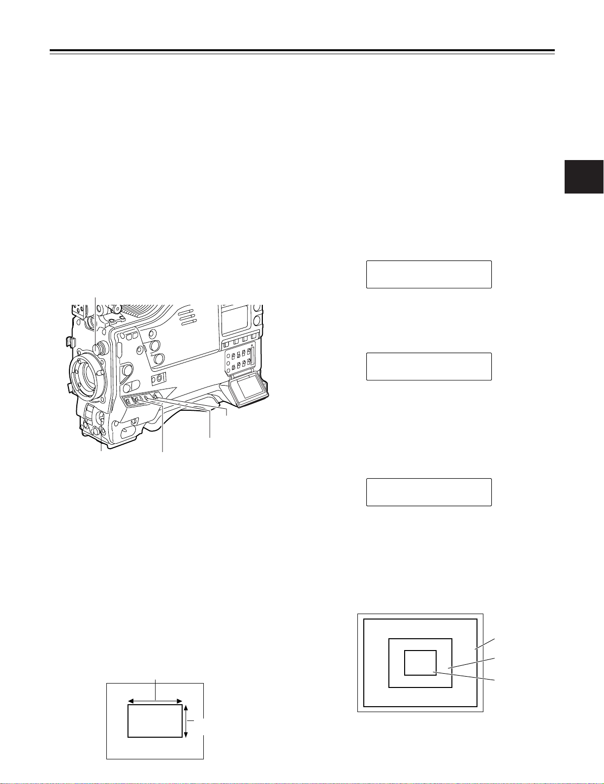
Chapter 4
Adjustments and settings for recording
In order to achieve images with a consistently high picture
quality with this unit, it is necessary to adjust the black balance
and white balance as the individual conditions demand. To
achieve a higher picture quality, it is recommended that the
adjustments be performed in the following sequence: AWB
(white balance adjustment) > ABB (black balance
adjustment) > AWB (white balance adjustment).
4-1
Adjusting the white balance and black balance
4-1-1 Adjusting the white balance
The white balance must always be re-adjusted when the
lighting conditions have changed.
The white balance is adjusted automatically by following the
steps below.
Set the switches as shown in the figure.
1
CC FILTER/ND FILTER controls
Adjust the lens aperture.
4
Set the AUTO W/B BAL switch to AWB, and then release
5
it.
The switch returns to the center, and the white balance is
automatically adjusted.
<Note>
When the AUTO W/B BAL switch is pressed again to the
AWB side when the white balance is being adjusted
automatically (AWB ACTIVE), the adjustment operation
will stop.
The adjusted value in this case is the value before
automatic adjustment was performed.
While the adjustment is in progress, the following
6
message appears on the viewfinder screen.
AWB ACTIVE
Adjustment is completed in several seconds. (A message
7
similar to the one shown in the figure below now appears.)
The adjustment value is automatically saved in the
memory (A or B) which was set in step 1.
4
WHITE BAL: A or B
OUTPUT: CAM
AUTO W/B BAL switch:
Use this to execute AWB.
Select the CC FILTER/ND FILTER controls setting in
2
accordance with the lighting conditions.
<Note>
For examples of the FILTER controls settings, refer to “23 Shooting and recording/playback function section.”
Erect a white pattern at a place with the same conditions
3
as the source of light illuminating the subject, zoom in,
and shoot the white of the pattern on the screen. A white
object (such as a white cloth or white wall) near the
subject may be used as a substitute for the white pattern.
The size of the white object required is shown in the
figure below.
<Notes>
≥Take care to keep high-brightness spots off the screen.
≥Shoot white objects in the center of the screen.
At least one-fourth of the screen width
GAIN: Normally 0 dB
Set to a more suitable gain level
if it is too dark.
AWB A OK 3.2K
The message shown in the figure below appears when
8
the color temperature of the subject falls below 2300 K or
rises above 5600 K.
The downward pointing arrow indicates that the color
temperature is lower than the display temperature;
conversely, an upward pointing arrow indicates that the it
is higher than the display temperature.
AWB A OK 2.3K
m
White balance detection area
The white balance detection area setting can be changed to
90%, 50% or 25% by opening the <WHITE BALANCE
MODE> screen from the OPERATION page and selecting the
desired setting for the AWB AREA item by performing menu
operations.
The factory setting is 25%.
90%
50%
25%
At least one-fourth of
the screen height
27

Chapter 4
Adjustments and settings for recording
When there is no time to adjust the white balance
Set the WHITE BAL switch to PRST. The white balance for
the filter is achieved in accordance with the setting position of
the FILTER control (outer).
When the white balance cannot be adjusted
automatically
When the white balance adjustment was not completed
correctly, one of the following error messages will appear on
the viewfinder screen. When an error message is displayed,
take the recommended action, and try adjusting the white
balance again. If the error message persists even after
repeated attempts, the inside of the unit must be inspected.
For details, contact your nearest service center or your dealer.
Messages relating to white balance adjustment
Error
message
COLOR TEMP.
HIGH
LOW
LOW LIGHT There is not enough light.
LEVEL OVER There is too much light.
CHECK FILTER The setting position of the
TIME OVER AWB was not completed
Color temperature is too
high.
Color temperature is too
low.
filter selector control is not
correct.
within the allotted time.
Meaning Recommended action
Select a suitable filter.
Select a suitable filter.COLOR TEMP.
Increase the amount of light
or increase the gain.
Reduce the amount of light
or reduce the gain.
Check the filter selector
control.
The shooting conditions
may be unstable. If flicker
occurs, engage the shutter
and shoot again under
stable conditions.
Viewfinder screen displays relating to the white
balance
For details, refer to “4-7 Viewfinder screen status displays.”
White balance memories
The values stored in the memories are retained even after the
unit’s power has been turned off until the white balance is
next adjusted. There are two sets of white balance memories,
A and B.
When ON has been selected (initial setting) as the setting for
the FILTER INH item on the <WHITE BALANCE MODE>
screen opened from the OPERATION page by performing
menu operations, the number of memories is limited to one in
A and one in B. In this case, the memory contents are not
coupled with the CC filter.
When FILTER INH is set to OFF, the adjustment values for
each CC filter can be automatically saved in the memories
corresponding to the WHITE BAL switch settings (A or B).
This unit contains four filters so that a total of 8 (4a2)
adjustment values are saved.
Note that when VAR has been selected for AWB A and AWB
B items of the <WHITE BALANCE MODE> screen, the values
will be the fixed color temperature settings established with
the COLOR TEMP A and COLOR TEMP B settings and they
cannot be adjusted using the AWB switch.
28
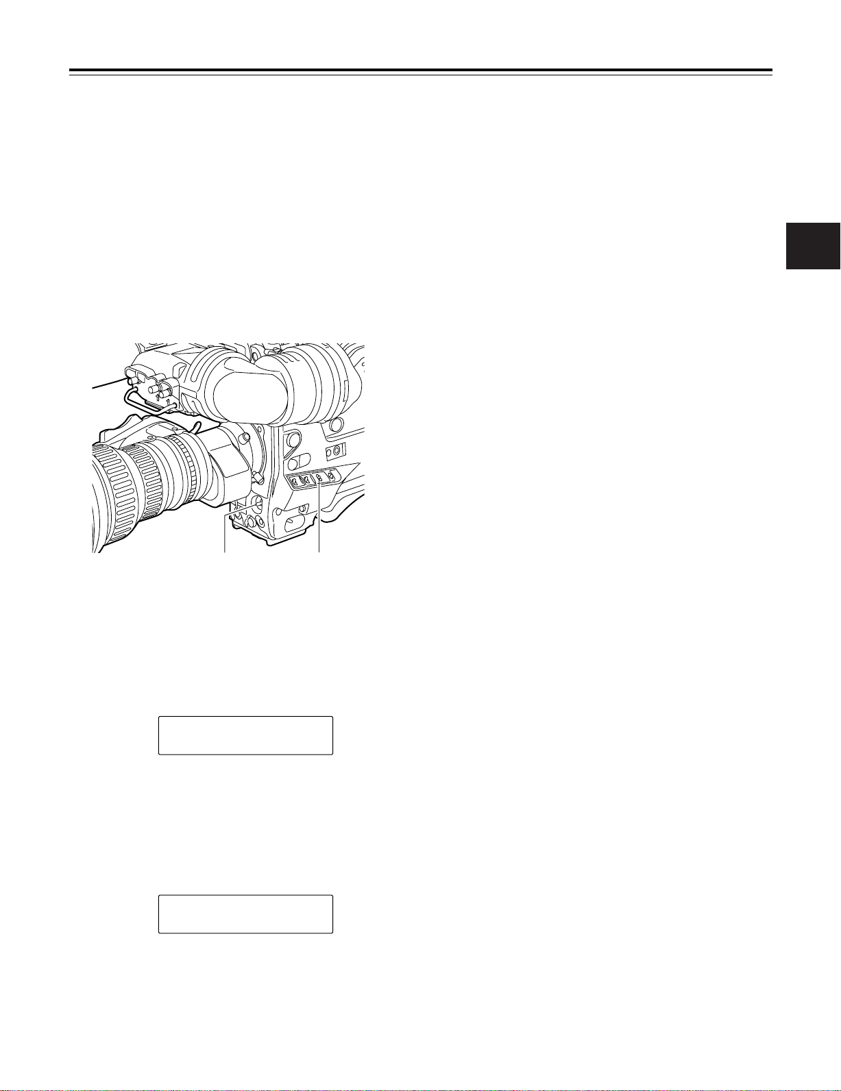
Chapter 4
Adjustments and settings for recording
4-1-2 Adjusting the black balance
The black balance needs to be adjusted in the following
cases:
≥When the unit is used for the first time
≥When the unit is used after it has not been used for a
prolonged period of time
≥When the unit is used in an ambient temperature which has
fluctuated significantly
≥When the value selected for the gain switch has been
changed
≥When the super gain setting has been performed using the
USER MAIN, USER1 or USER2 button
≥When the gamma ON/OFF setting has been changed
Set the switches as shown in the figure.
1
<Notes>
≥Check that the lens connector has been connected and
that the lens aperture is set to CLOSE.
≥While the black balance is being adjusted, the aperture
is automatically set to the light-shielding status.
≥While the black balance is being adjusted, the gain
selector circuit is switched automatically.
Flicker or noise may appear on the viewfinder screen,
but this is not indicative of malfunctioning.
≥If the black shading is still unsatisfactory although the
“ABB OK” message is displayed, perform menu
operations to open the <BLACK SHADING> screen
from the MAINTENANCE page, move the arrow mark
(>) to the DETECTION item, press the JOG dial
button, and proceed with the black shading adjustment.
If the ABB switch is held down for 5 or more seconds,
the black shading can be automatically adjusted after
the ABB operation. (See the SHD.ABB SW CTL item
under “7-5-5 SW MODE.”)
≥If the AUTO W/B BAL switch is pushed down to the
ABB position again while the black balance is being
automatically adjusted (ABB ACTIVE), the adjustment
will be aborted.
The adjusted value in this case is the value before
automatic adjustment was performed.
4
AUTO W/B BAL switch:
Use this to execute ABB.
Set the AUTO W/B BAL switch to the ABB position, and
2
then release it.
The switch returns to the center, and the adjustment is
performed.
While the adjustment is in progress, the following
3
message appears on the viewfinder screen.
ABB ACTIVE
<Note>
While the adjustment is in progress, the lens aperture is
automatically set to CLOSE.
Adjustment is completed in several seconds. (A message
4
similar to the one shown in the figure below now appears.)
The adjustment value is automatically saved in the
memory.
OUTPUT: CAM
Black balance memory
The values stored in the memory are retained even after the
unit’s power has been turned off.
ABB OK
29
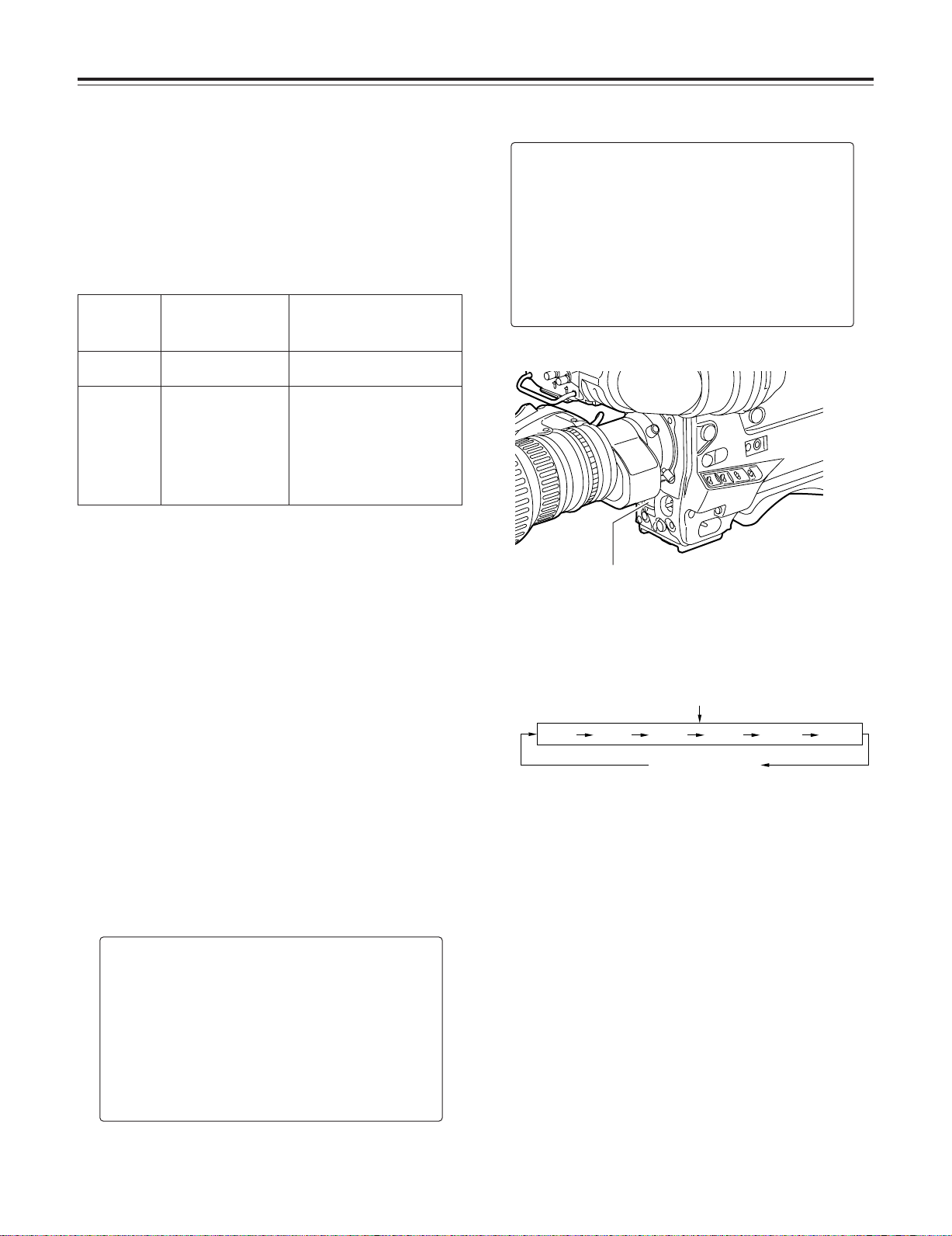
Chapter 4
POSITION
1
POSITION2POSITION3POSITION4POSITION5POSITION
6
Adjustments and settings for recording
4-2 Setting the electronic shutter
This section describes the unit’s electronic shutter, its settings
and operations.
4-2-1 Shutter modes
The table below lists the shutter modes in which the unit’s
electronic shutter can be used as well as the shutter speeds
which can be selected.
Mode Shutter speed Applications
Standard POSITION1 - 6
SYNCHRO
SCAN
When the camera modo
is 50i
Within the
209.4
Hz range
When the camera modo
is 25P
Within the
209.4
Hz range
50.2
25.2
For shooting fast-moving subjects
clearly.
For shooting monitor screens in a
way that minimizes the pattern of
horizontal lines.
Hz to
Hz to
<Notes>
O No matter in which mode the electronic shutter is used, the
higher the shutter speed, the lower the camera’s sensitivity.
O When the aperture is in the automatic mode, it will
increasingly open and the depth of focus will become
shallower as the shutter speed is increased.
4-2-2 Setting the shutter mode and speed
The shutter speeds used in the shutter mode are set by
switching the SHUTTER switch.
The shutter speeds in the SYNCHRO SCAN mode can easily
be changed using the SYNCHRO SCAN (+ and –) buttons on
the side panel.
Open the <SHUTTER SPEED> screen and <SHUTTER
SELECT> screen from the OPERATION page by performing
menu operations. It is now possible to restrict the shutter
speed selection range to the required range beforehand
and/or select whether to use the SYNCHRO SCAN mode and
SUPER V mode beforehand.
Once selected, the shutter speed is retained even after the
unit’s power has been turned off.
#
< SHUTTER SELECT >
POSITION1 SEL :1/60
POSITION2 SEL :1/120
POSITION3 SEL :1/250
POSITION4 SEL :1/500
POSITION5 SEL :1/1000
POSITION6 SEL :1/2000
Press the SHUTTER switch from ON to SEL.
1
SHUTTER switch
Press the SHUTTER switch to the SEL position again,
2
and repeat this until the desired mode or speed is
displayed.
When all the modes and speeds are displayed, the
display will change in the sequence shown below.
Standard mode
SYNCHRO SCAN
mode
Viewfinder screen displays relating to the shutter
For details, refer to “4-7 Viewfinder screen status displays.”
#
< SHUTTER SPEED >
SYNCHRO SCAN :ON
POSITION1 :ON
POSITION2 :ON
POSITION3 :ON
POSITION4 :ON
POSITION5 :ON
POSITION6 :ON
30
 Loading...