

Page 1

HD/SD Multi Format DVCPRO Server
AJ- P
Operating Instructions
Page 2

2
Copyright (c) 1994 Washington University in Saint Louis
All rights reserved.
This product includes software developed by Washington University in Saint Louis and its contributors.
Copyright (c) 1980, 1985, 1988, 1989, 1990 Regents of the University of California.
All rights reserved.
This product includes software developed by the University of California, Berkeley and its contributors.
Redistribution and use in source and binary forms, with or without modification, are permitted
provided that the following conditions are met:
1. Redistributions of source code must retain the above copyright notice, this list of conditions and
the following disclaimer.
2. Redistributions in binary form must reproduce the above copyright notice, this list of conditions
and the following disclaimer in the documentation and/or other materials provided with the
distribution.
3. All advertising materials mentioning features or use of this software must display the following
acknowledgement: This product includes software developed by the University of California,
Berkeley and its contributors.
4. Neither the name of the University nor the names of its contributors may be used to endorse or
promote products derived from this software without specific prior written permission.
THIS SOFTWARE IS PROVIDED BY THE REGENTS AND CONTRIBUTORS “AS IS” AND ANY
EXPRESS OR IMPLIED WARRANTIES, INCLUDING, BUT NOT LIMITED TO, THE IMPLIED
WARRANTIES OF MERCHANTABILITY AND FITNESS FOR A PARTICULAR PURPOSE ARE
DISCLAIMED. IN NO EVENT SHALL THE REGENTS OR CONTRIBUTORS BE LIABLE FOR
ANY DIRECT, INDIRECT, INCIDENTAL, SPECIAL, EXEMPLARY, OR CONSEQUENTIAL
DAMAGES (INCLUDING, BUT NOT LIMITED TO, PROCUREMENT OF SUBSTITUTE GOODS
OR SERVICES; LOSS OF USE, DATA, OR PROFITS; OR BUSINESS INTERRUPTION)
HOWEVER CAUSED AND ON ANY THEORY OF LIABILITY, WHETHER IN CONTRACT,
STRICT LIABILITY, OR TORT (INCLUDING NEGLIGENCE OR OTHERWISE) ARISING IN
ANY WAY OUT OF THE USE OF THIS SOFTWARE, EVEN IF ADVISED OF THE POSSIBILITY
OF SUCH DAMAGE.
Page 3
3
CAUTION
RISK OF ELECTRIC SHOCK
DO NOT OPEN
CAUTION: TO REDUCE THE RISK OF ELECTRIC SHOCK,
DO NOT REMOVE COVER (OR BACK).
NO USER SERVICEABLE PARTS INSIDE.
REFER TO SERVICING TO QUALIFIED SERVICE PERSONNEL.
The lightning flash with arrowhead symbol,
within an equilateral triangle, is intended to
alert the user to the presence of uninsulated
“dangerous voltage” within the product’s
enclosure that may be of sufficient magnitude
to constitute a risk of electric shock to
persons.
The exclamation point within an equilateral
triangle is intended to alert the user to the
presence of important operating and
maintenance (service) instructions in the
literature accompanying the appliance.
indicates safety information.
CAUTION:
O
Keep the temperature inside the rack to
betwenn 41°F to 95°F (5°C to 35°C).
O
Bolt the rack securely to the floor so that it
will not topple over when this unit is drawn
out.
IMPORTANT
“Unauthorized recording of copyrighted
television programs, video tapes and other
materials may infringe the right of copyright
owners and be contrary to copyright laws.”
WARNING:
TO REDUCE THE RISK OF FIRE OR SHOCK
HAZARD, DO NOT EXPOSE THIS EQUIPMENT
TO RAIN OR MOISTURE.
CAUTION:
TO REDUCE THE RISK OF FIRE OR SHOCK
HAZARD AND ANNOYING INTERFERENCE,
USE THE RECOMMENDED ACCESSORIES
ONLY.
CAUTION:
TO REDUCE THE RISK OF FIRE OR SHOCK
HAZARD, REFER INSTALLATION OF HARDDISK DRIVE TO QUALIFIED SERVICE
PERSONNEL.
HARD-DISK DRIVE MUST BE APPROVED BY
UL AND/OR CSA.
CAUTION:
TO REDUCE THE RISK OF FIRE OR SHOCK
HAZARD, REFER CHANGE OF SWITCH
SETTING INSIDE THE UNIT TO QUALIFIED
SERVICE PERSONNEL.
CAUTION:
TO REDUCE THE RISK OF FIRE OR SHOCK
HAZARD, REFER MOUNTING OF THE
OPTIONAL INTERFACE BOARD TO
QUALIFIED SERVICE PERSONNEL.
FCC Note:
This device complies with Part 15 of the FCC Rules. To
assure continued compliance follow the attached
installation instructions and do not make any
unauthorized modifications.
This equipment has been tested and found to comply
with the limits for a class A digital device, pursuant to
Part 15 of the FCC Rules. These limits are designed to
provide reasonable protection against harmful
interference when the equipment is operated in a
commercial environment. This equipment generates,
uses, and can radiate radio frequency energy and, if not
installed and used in accordance with the instruction
manual, may cause harmful interference to radio
communications. Operation of this equipment in a
residential area is likely to cause harmful interference in
which case the user will be required to correct the
interference at his own expense.
CAUTION:
Do not install or place this unit in a bookcase,
built-in cabinet or any other confined space in
order to maintain adequate ventilation. Ensure
that curtains and any other materials do not
obstruct the ventilation to prevent risk of
electric shock or fire hazard due to
overheating.
Page 4

4
O
Windows, Windows 95, Windows 98 and Windows NT are registered trademarks of Microsoft Corporation.
O
Pentium is a registered trademark of Intel Corporation.
All other names of companies and products are the trademarks or registered trademarks of the companies
concerned.
Handling Precautions . . . . . . . . . . . . . . . . 5
Features . . . . . . . . . . . . . . . . . . . . . . . . . . . 6
System Configuration . . . . . . . . . . . . . . . . 7
Parts and Their Functions . . . . . . . . . . . . 8
Front panel . . . . . . . . . . . . . . . . . . . . . . . . . . . . . . 8
Rear panel . . . . . . . . . . . . . . . . . . . . . . . . . . . . . . 10
Rack Mounting. . . . . . . . . . . . . . . . . . . . . 12
Connections. . . . . . . . . . . . . . . . . . . . . . . 13
1. Analog . . . . . . . . . . . . . . . . . . . . . . . . . . . . . . . 13
2. SDTI . . . . . . . . . . . . . . . . . . . . . . . . . . . . . . . . 14
3. SDT . . . . . . . . . . . . . . . . . . . . . . . . . . . . . . . . . 15
Starting Up and Closing Down the
System . . . . . . . . . . . . . . . . . . . . . . . . . . . 16
System Start Up . . . . . . . . . . . . . . . . . . . . . . . . . 16
System Shutdown/Power Off. . . . . . . . . . . . . . . . 16
Display Panel . . . . . . . . . . . . . . . . . . . . . . 17
Display panel screen flowchart . . . . . . . . . . . . . . 17
Main Screen . . . . . . . . . . . . . . . . . . . . . . . . . . . . 17
Menu Selection Screen . . . . . . . . . . . . . . . . . . . . 18
Shutdown Setting Screen . . . . . . . . . . . . . . . . . . 21
Shutdown Screen . . . . . . . . . . . . . . . . . . . . . . . . 21
Channel Setting Screen. . . . . . . . . . . . . . . . . . . . 21
Parameter Setting Screen . . . . . . . . . . . . . . . . . . 22
Version Display Screen . . . . . . . . . . . . . . . . . . . . 22
Error Display Screen . . . . . . . . . . . . . . . . . . . . . . 24
CLIP Display Screen . . . . . . . . . . . . . . . . . . . . . . 25
CLIP Erase Screen . . . . . . . . . . . . . . . . . . . . . . . 25
CLIP Rename Screen . . . . . . . . . . . . . . . . . . . . . 25
Simplified Manual Operation Screen . . . . . . . . . . 26
CLIP Load Screen . . . . . . . . . . . . . . . . . . . . . . . . 28
CLIP Creation Screen . . . . . . . . . . . . . . . . . . . . . 28
HDD Status Display Screen . . . . . . . . . . . . . . . . 29
HDD Reconstruction Selection Screen . . . . . . . . 29
Error Log Display Screen . . . . . . . . . . . . . . . . . . 30
Error Log Detailed Display Screen . . . . . . . . . . . 30
Contents
Optional Board Installation Method. . . . 31
1. Analog I/O board (AJ-YA7000P) . . . . . . . . . . . 32
2. Analog out board (AJ-YA7200P) . . . . . . . . . . . 33
3. SDTI I/O board (AJ-YAC7000P) . . . . . . . . . . . 34
4. SDI I/O board (AJ-YA7100P). . . . . . . . . . . . . . 35
Optional HDD . . . . . . . . . . . . . . . . . . . . . . 36
Troubleshooting . . . . . . . . . . . . . . . . . . . 37
Connector Signals. . . . . . . . . . . . . . . . . . 38
Specifications . . . . . . . . . . . . . . . . . . . . . 40
Page 5

5
O
This unit has been designed with foremost
emphasis placed on its reliability as a transmission
server. However, to prevent accidents in
transmission due to breakdown or obstructions, it is
requested that the server be used with a system
compiled in duplicate.
O
By having a newly-developed RAID device built in,
the system is designed for continuous operation
even if one HDD (hard disk drive) unit breaks down.
However, to avoid secondary complications, if one
HDD unit breaks down, terminate operation
immediately and request servicing from your dealer.
O
The system is designed so that a faulty HDD can
be replaced even while continuity is maintained, but
normal operation thereafter cannot be guaranteed.
Do not replace a HDD during recording or playback.
O
The system is designed to facilitate data restoration
by replacing a faulty HDD with a new one, but
backup copies of data on recording tape, etc.,
should be made so that important contents
recorded on the HDD are not lost due to equipment
problems, etc.
Faulty equipment can be serviced by your dealer
but lost contents cannot be restored.
O
Do not execute recording or playback while data is
being rebuilt.
If recording or playback is not being executed, the
system disk (9GB) can be rebuilt in approximately
10 minutes and data disks (36GB) can be rebuilt in
about 1 hour.
O
Do not use this unit in a vehicle.
This may cause injury or result in problems with the
hard disk drive or data.
O
It takes about 3 seconds to switch to REC mode
when the REC command is sent in REC CUEUP
mode.
O
When an HDD is loaded onto this system, extra
weight is added to the front panel side. Please note
this fact and exercise due caution when moving the
system.
O
Whenever a problem occurs with POWER A or
POWER B in the power supply unit, be sure to
always turn the relevant power supply switch to
OFF.
Handling Precautions
$
Precautions for video and audio input/output
operations
O
For input/output of HD signal from VTR to the
server, use a codex unit that is compatible with the
server.
O
Use the AJ-D780 when using the SDTI 4aspeed
for input/output from a VTR to the server.
O
When using the SDTI 1aspeed for input/output
from a VTR to the server, use a VTR mounted with
SDTI baseboard such as AJ-D850, AJ-D950 or AJD960.
The AJ-D780 does not have a SDTI 1aspeed
function.
O
When using analog or SDI input/output, signals
buried in the video blanking area (e.g., signals for
letter broadcasting) cannot be recorded or played
back.
Recording and playback are possible when a SDTI
I/O board is used.
Page 6

6
DVCPRO compression
This digital video server incorporates the DVCPRO
format that, in the development of digital technology
for broadcasting applications, has won critical acclaim
for its high picture and sound quality.
High-speed transmission made possible
by an SDTI interface
The existing SDI (SMPTE259M-C) router and cable
can be used without modification. Further, by
employing an SDTI interface capable of transmission
at 4aspeed (case of DVCPRO 25 Mbps), it is
possible to upload or download image data to and
from a 4aspeed VTR (AJ-D780).
Multiple channels are also possible if the unit is used
as the cache for a VTR system.
With an SDTI interface, input/output of all DVCPRO
format signals (DVCPRO 25M/50M/P/HD) is possible.
4 channel input/output with 20-hour
recording capacity
This 4-channel server (2-channel with HD) can make
input/output changes using commands so that it is
easy to manage multiple channels and simple to
construct time-difference systems, etc. The running
costs of systems requiring repeat playback can be
pared back since there is none of the deterioration
found with tapes.
By using a 36GB HDD (optional), approximately 20
hours of recording capacity is obtained.
(When 8 units of HDD for DVCPRO 25 Mbps/data are
used.)
High reliability with built-in RAID
Thanks to built-in RAID, the system has been
configured with system disk at RAID 1, and data disk
at RAID 3, so operation can be continued even if one
HDD unit malfunctions. An HDD system of high
reliability is thus achieved.
I/O and Strage capacities can be
expanded by Fibre Channel connection
Expanding input/output channels and strage capacity
is easy because I/O and Strage are connected via
Fibre Channel.
VTR-like server with RS-422A control
Since the server controls each channel using an RS422A serial interface, it can provide control using
images that appear to involve 4 VTRs.
Odetics and Louth protocols supported
This server supports both the Odetics and Louth
automation protocols used in broadcast stations so
that it can easily be connected as a unit to be subject
to the automation control inside a broadcast station.
Emergency operation possible with front
panel operation
Front panel operation makes it possible to control
selection of recorded materials during an emergency
and playback of the same.
When the alarm activates, alarm contents are
displayed so that restorative measures can be taken
in response to messages.
Error detection functions
The display panel comes with functions for detecting
and displaying fan stoppages, hard disk drive errors
and system errors so that warnings can be issued in
the unlikely event of a breakdown.
Optional SDTI, analog and SDI
input/output
An SDTI I/O board capable of 4x speed operation, an
analog I/O board that can be monitored, and a SDI I/O
board are available as audio/video input/output
options so the board that matches the interfaces used
in the broadcast station can be selected.
Redundant power supply to avoid
problems
The unit has dual power supply system to avoid any
problems with the power supply.
Features
Page 7
7
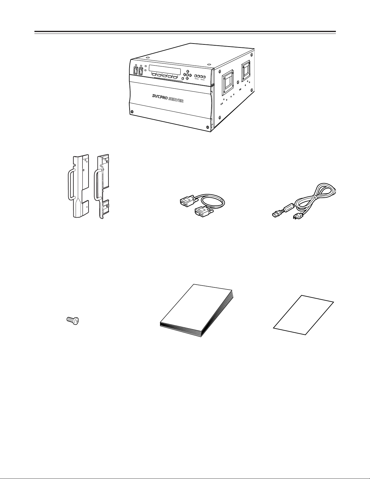
System Configuration
FC (Fibre Channel) cable
Operating Instructions
(what you are now reading)
Power cord (a2)
HDD mounting screws (aa36)
6U rack mount adapter
DVCPRO server
Warranty
Page 8
8
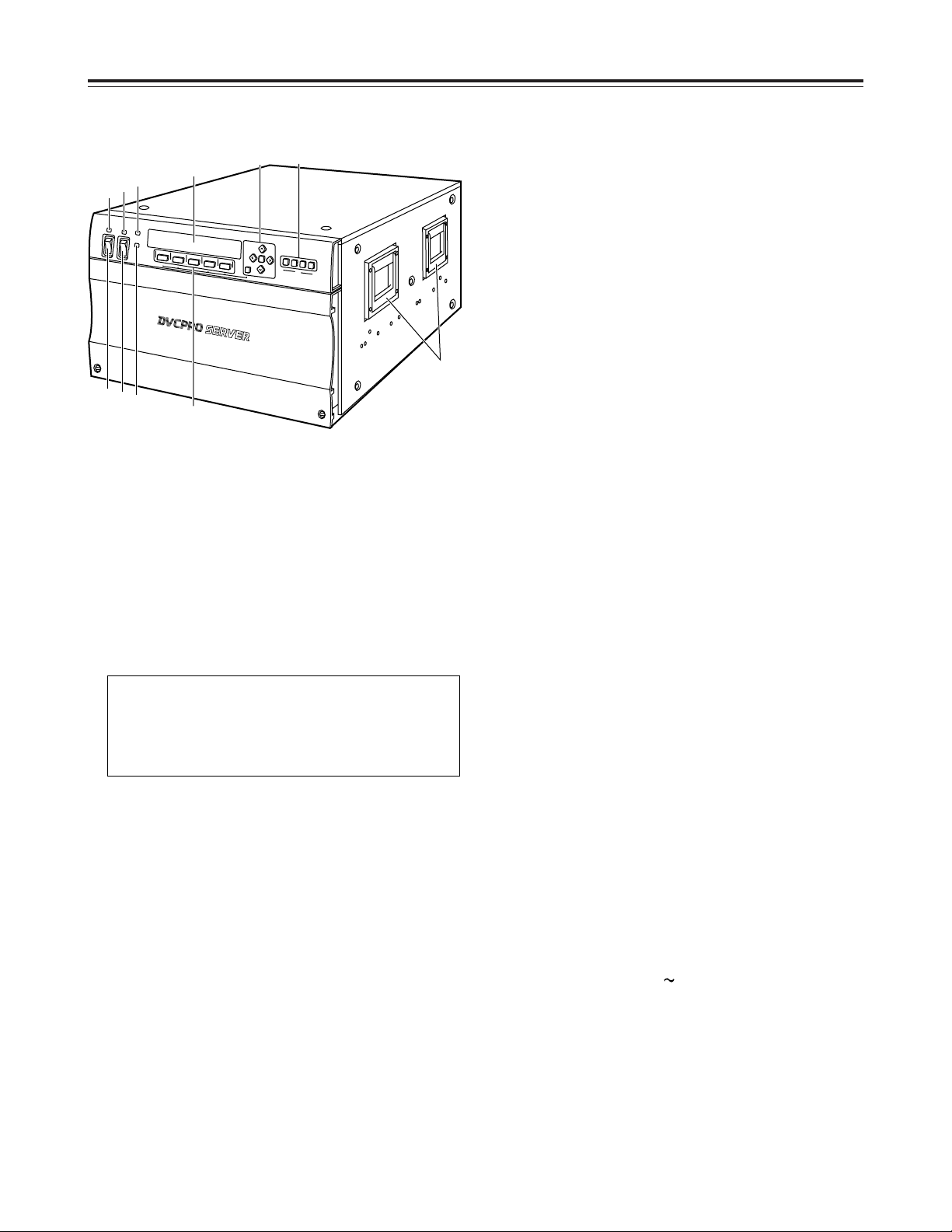
Parts and Their Functions
1
Power switch [POWER A]
This switch is used to turn the unit’s [POWER A]
supply ON or OFF.
Before turning the power off, execute SHUTDOWN
from the display panel and wait for the display to
read: “It is now safe to turn off.”
Turning the power off during operation may destroy
data or cause the hard disk drive to fail.
2
Power switch [POWER B]
This switch is used to turn the unit’s [POWER B]
supply ON or OFF.
3
Power LED [POWER A]
This lights when power is supplied to POWER A.
It goes off when the power switches of both
POWER A and POWER B are at OFF.
Green LED: No anomalies
Red LED:
O
There is something wrong with the output
voltage, cooling fan or power supply module
temperature.
O
While the POWER B switch is at ON, the
POWER A switch has been turned to OFF or
the POWER A supply unit has not been
installed.
The unit has dual power supply system to avoid
any problems with the power supply.
If a problem arises with either POWER A or
POWER B, the unit operates with the other power
supply.
4
Power LED [POWER B]
This lights when power is supplied to POWER B.
It goes off when the power switches of both
POWER A and POWER B are at OFF.
Green LED: No anomalies
Red LED:
O
There is something wrong with the output
voltage, cooling fan or power supply module
temperature.
O
While the POWER A switch is at ON, the
POWER B switch has been turned to OFF or
the POWER B supply unit has not been
installed.
5
WARNING LED [WARNING]
During SILENT-MODE:
The lamp turns orange and blinks whenever
something goes wrong with the unit.
In the event of a slight error, this lamp goes out
after the error log is checked.
In the event of a gross error, the lamp lights in red.
During ATTN-MODE:
The lamp turns orange and blinks whenever
something goes wrong with the unit. The error
display menu appears on the display panel and at
the same time, the alarm sounds.
To stop the alarm, press the [F3] button.
In the event of a gross error, the lamp lights in red.
6
HDD LED [HDD]
This lamp blinks when a built-in HDD has been
accessed. It blinks green when all the built-in HDDs
are operating normally, and lights in orange during
reconstruction. In the event of a problem with any
one of the HDD units (including those not yet
inserted), the lamp blinks red to give notice.
7
Display panel
Displays the status of channel selected with
channel select button, along with information on the
unit internals.
The display menu is changed by using function
button (8) or cursor button (9).
8
Function buttons [F1
F5]
Used when executing any of the functions shown in
the lower register of the display panel.
The operations allocated to each function on the
menu are carried out by pressing these buttons.
Front panel
12
3
4
CH
F1
B
W
A
R
N
IN
G
H
D
D
P
O
W
E
R
A
O
N
O
F
F
F
2
F3
F4
F
5
CA
N
C
EL
R
EC
U
E
E
M
R
P
L
A
Y
R
E
M
O
T
E
/L
O
C
A
L
TC
/C
TL
CTL
R
ESE
T
FUN
C
TION
5
4
3
7
9
;
:
1
2
6
8
Page 9

9
Parts and Their Functions
9
Cursor buttons [#, 2, !, 1, SET, CANCEL]
[#] button:
Becomes effective when the 3mark is shown on
the display panel.
Forwarding of CLIP, etc., character selection and
separate function menu are displayed.
[2] button:
Becomes effective when the 4mark is shown on
the display panel.
Forwarding of CLIP, etc, character selection and
separate function menu are displayed.
[!] button:
Becomes effective when the 2mark is shown on
the display panel or the cursor (_) is present.
Moves the cursor one space to the left.
[1] button:
Becomes effective when the 1mark is shown on
the display panel or the cursor is present. Moves
the cursor one space to the right.
[SET] button:
Becomes effective when “SET or CANCEL” is
shown on the display panel. Pressing the SET
button establishes selection or setting and
designated operations take place.
[CANCEL] button:
Becomes effective when “SET or CANCEL” is
shown on the display panel. Pressing the
CANCEL button erases selection or setting, and
the previous screen is restored without anything
taking place.
:
Channel buttons [CH1
CH4]
Designates the channel shown on the display
panel. The button of the selected channel lights and
the selected channel status is shown on the
display.
Channel 1 is selected for power supply start up.
Unit internal settings, HDD status, error status and
other conditions for which no channel is designated
can be viewed on the display irrespective of the
channel selected.
;
Handle
Combining the CANCEL button with
function buttons
Targeted operation takes place by pressing the
function button while keeping the CANCEL button
depressed.
Effective only on main menu.
Processes other than LOCAL/REMOTE changeover
are effective only in local mode.
[CANCEL]+[F1] (RECUE):
Re-cues clip currently being loaded.
[CANCEL]+[F2] (EMR PLAY):
Executes emergency playback.
When the EMR-OUT1 clip is present, it is loaded
and playback occurs repeatedly. When that clip is
absent, playback of the clip currently being loaded
begins from the current stop position, and after
playback to the end position, return is made to the
clip head position and playback is repeated.
[CANCEL]+[F3] (REMOTE/LOCAL):
Switches the channel currently shown on the
display between remote mode and local mode.
Switch is made between REMOTE and LOCAL
each time [CANCEL] + [F3] is pressed.
REMOTE:
The unit is controlled from an external controller.
Operations cannot be performed with the front
panel.
LOCAL:
The unit is controlled from the front panel.
Operations cannot be performed with the
external controller.
[CANCEL]+[F4] (TC/CTL):
Displays the time code mode. Each time the button
is pressed, switching occurs as follows:
TC5CTL15CTL25TC.
[CANCEL]+[F5] (CTL RESET):
When the [CANCEL] + [F5] button is pressed at
CTL1, the time code is reset to 00:00:00:00.
Front panel
Page 10
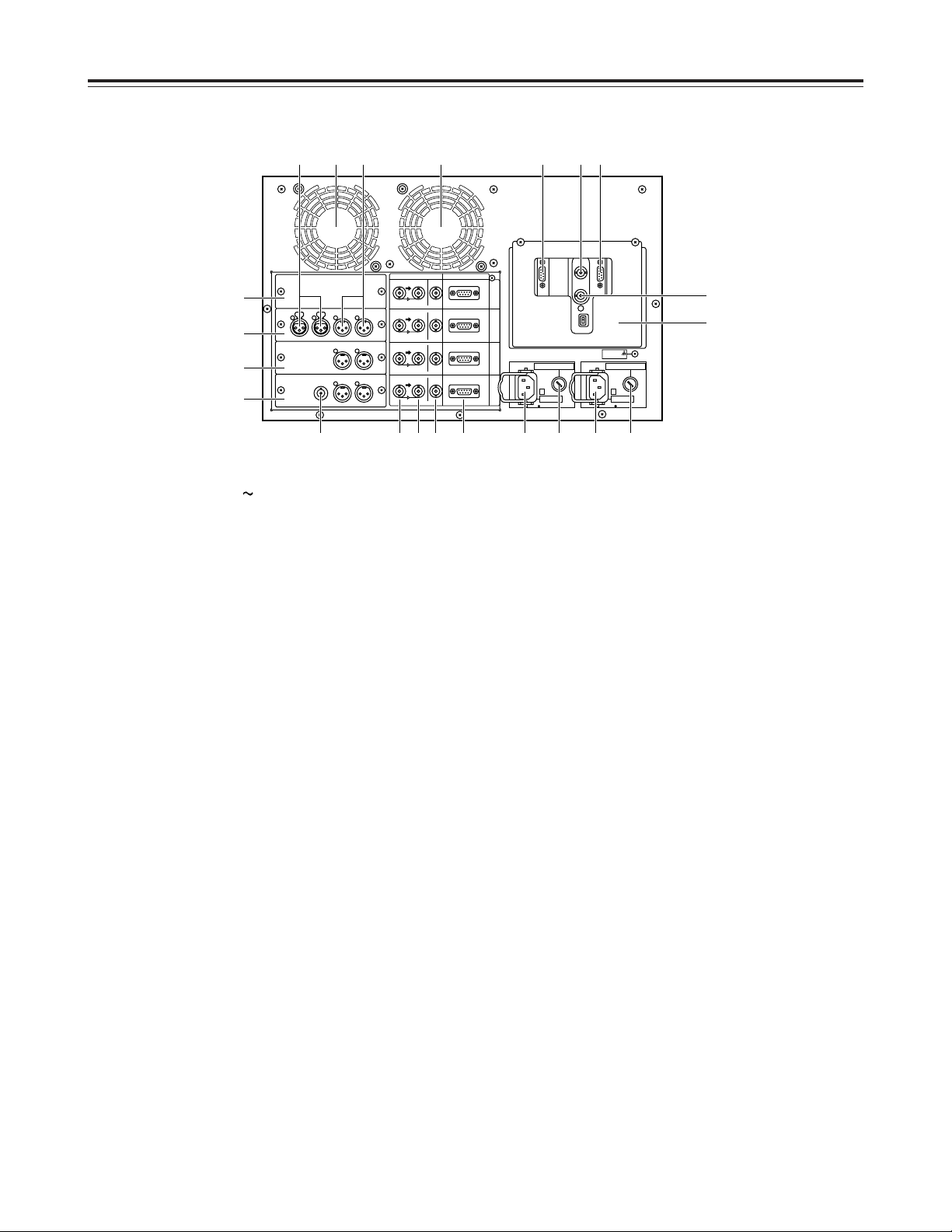
10
9
Video output connector [OUT]
Video signal output connectors for each of the
server’s channels.
During SDI and SDTI signals output the embedded
audio signals are output from these connectors.
:
Analog reference video signal input connector
[REF IN]
The analog reference video signal is input to this
connector.
A stable black-burst signal from an external sync
signal generator is also input to this connector.
;
Analog reference video signal through output
connector
<
Fibre Channel connector [RAID]
Fibre Channel connector for RAID.
=
Fibre Channel connector [HOST]
Fibre Channel connector for HOST.
Connects FC cable in the same package to Fibre
Channel connector for RAID.
>
Connector cover
This cover is to avoid connections which are not
necessary for normal operation.
As a shock watcher is attached to the cover to
detect any shocks, the cover should only be
removed for maintenance.
1
AC power socket [
AC IN]
This power socket is for [POWER A].
Connect the power cord (supplied) to this socket.
2
Fuse holder 1 [FUSE F1]
This fuse holder is for [POWER A].
Contains a 125V 10A fuse.
3
AC power socket [~ AC IN]
This power socket is for [POWER B].
Connect the power cord (supplied) to this socket.
4
Fuse holder 1 [FUSE F2]
This fuse holder is for [POWER B].
Contains a 125V 10A fuse.
5
Heat dissipating fan
Fan to keep the internal temperature from rising.
6
RS-422A connectors [REMOTE IN]
RS-422A connectors for controlling each of the
server’s channels.
7
Video signal input connector
[VIDEO IN, SDI/SDTI IN]
Video signal input connectors for each of the
server’s channels. Used for analog, SDI and SDTI
signals.
During SDI and SDTI input the embedded audio
signals are supplied to these connectors.
8
VIDEO through/buffer output connector
Video signal through (analog)/buffer (SDTI/SDI)
output connectors for each unit channel.
Parts and Their Functions
Rear panel
ANALOG/DIGITAL REMOTE IN
SIGNAL
GND
BA
C
H
1
C
H
2
C
H
3
C
H
4
SDI/SDTI IN
OUT
OUT
VIDEO IN
SDI/SDTI IN
OUT
OUT
VIDEO IN
SDI/SDTI IN
OUT
OUT
VIDEO IN
SDI/SDTI IN
OUT
OUT
VIDEO IN
~ AC IN
FUSE F2 125V 10A
~ AC IN
FUSE F1 125V 10A
3687E 9 4 21
?
@
A
B
;
>
5 : <=5 DC
Page 11

11
Parts and Their Functions
The following panels change depending on their
combination.
?
SDTI panel (packed with optional board)
Nothing is connected to the SDTI panel.
@
Analog panel (packed with optional board)
This is provided with analog audio signal input and
output connectors.
A
Analog out panel (packed with optional board)
This is provided with analog audio signal output
connectors.
B
SDI panel (packed with optional board)
This is provided with analog video signal output and
analog audio signal output connectors.
C
Analog audio signal input connectors
D
Analog audio signal output connectors
E
Analog video signal output connector
Four optional boards are available.
1. Analog I/O board (AJ-YA7000P)
2. Analog out board (AJ-YA7200P)
3. SDTI I/O board (AJ-YAC7000P)
4. SDI I/O board (AJ-YA7100P)
(The analog out board is required for the SDI
I/O board.)
The above four boards can be installed for any or all
of the four channels.
Consult your dealer for details on setting and
installing the optional boards.
Page 12
12
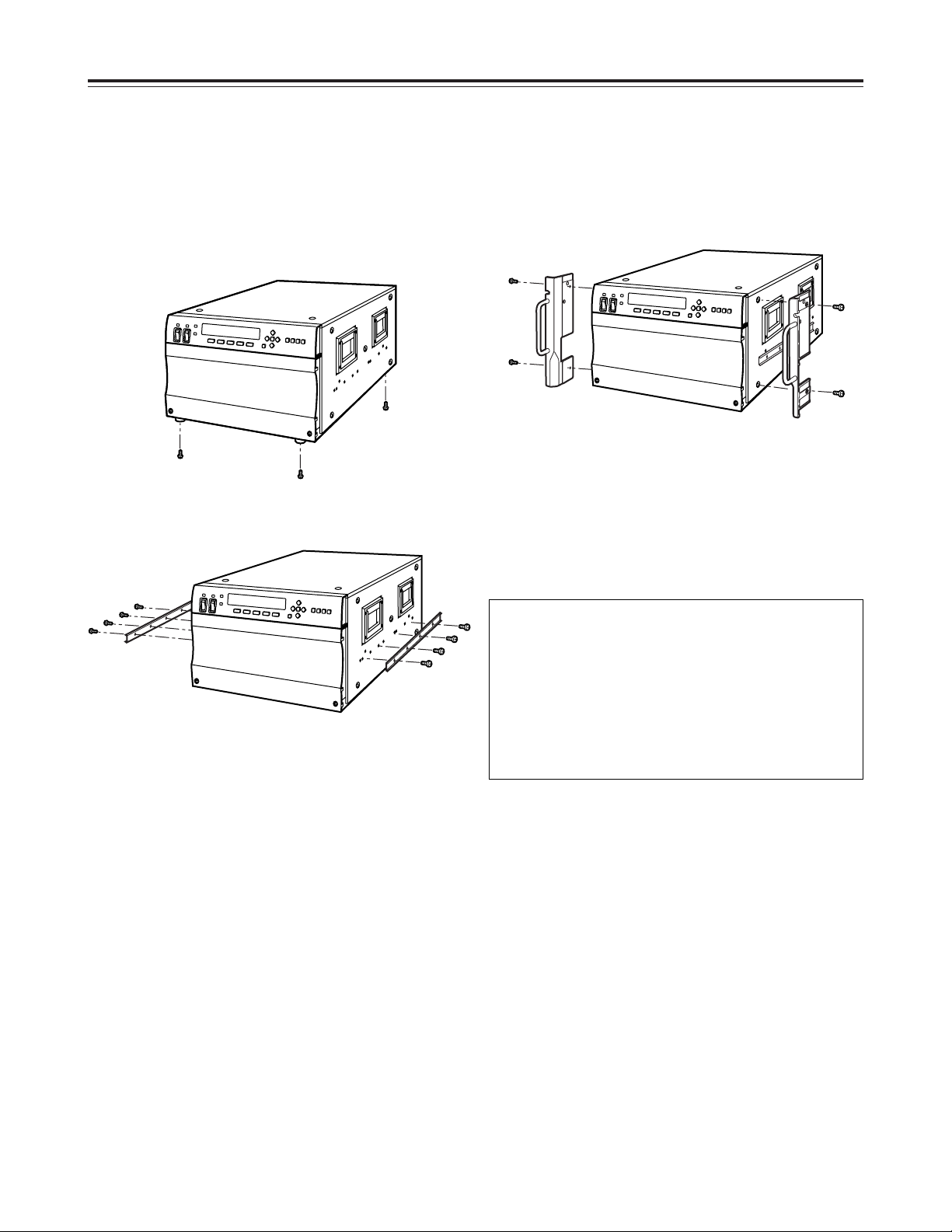
Rack Mounting
Using the rack-mounting adapters provided, the unit can be mounted in a 19-inch standard rack. The following
slide rails and brackets are recommended for mounting.
O
Slide rails (CC3001-99-0191), brackets (B-308): made by CHASIS TRAK
For details, consult your dealer.
1. Remove the four feet from the bottom of the unit.
O
Take care to safeguard the unit from vibration and
impact.
2. Attach the inner members of the slide rails to the
unit.
3. Attach the outer members of the slide rails and
brackets to the rack.
<Note>
Check that the height at the left and right is the
same.
O
There is a limit to the length of the screws which
can be used for rack mounting.
Use the accessory screws (M4a10) for the slide
rails.
If any of the accessory screws are lost or
misplaced, use replacement screws that are less
than 10 mm long.
O
Ensure the inner members are screwed in place at
the 4 locations on the left and right.
5. Release the inner member stoppers, and install the
unit in the rack. Once it has been installed, check
that it moves smoothly.
O
Use the mounting screws provided with the rackmounting adapters to attach these adapters.
O
Ensure the rack-mounting adapters are screwed in
place at the 2 locations on the left and right.
O
Keep the temperature inside the rack to between
41°F to 95°F (5°C to 35°C).
O
Bolt the rack securely to the floor so that it will not
topple over when this unit is drawn out.
O
When an HDD is installed, the unit becomes
heavier on the front panel side, so be careful
when removing the unit.
O
Do not move the unit while there is electrical flow,
as this could cause damage to the HDD or data.
4. Attach the rack-mounting adapters to the unit.
Page 13
13
ANALOG/DIGITAL REMOTE IN
SIGNAL
GND
BA
C
H
1
C
H
2
C
H
3
C
H
4
SDI/SDTI IN
OUT
OUT
VIDEO IN
SDI/SDTI IN
OUT
OUT
VIDEO IN
SDI/SDTI IN
OUT
OUT
VIDEO IN
SDI/SDTI IN
OUT
OUT
VIDEO IN
~ AC IN
FUSE F2 125V 10A
~ AC IN
FUSE F1 125V 10A
AUDIO INAUDIO OUTVIDEO OUT
AJ-D850
VIDEO IN
REF VIDEO IN
CONTROLLER
REFERENCE
VIDEO
Fibre Channel
Cable
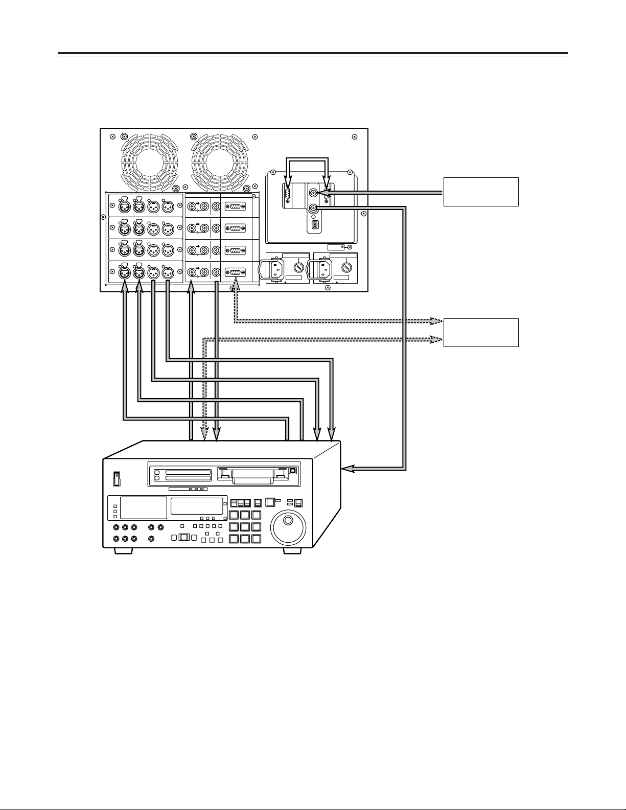
1. Analog
When all the connections have been made to the
analog I/O board
Connections
<Note>
No sound will be heard when a tape is played back at less than normal (1a) speed with this unit.
Page 14

14
ANALOG/DIGITAL REMOTE IN
SIGNAL
GND
BA
C
H
1
C
H
2
C
H
3
C
H
4
SDI/SDTI IN
OUT
OUT
VIDEO IN
SDI/SDTI IN
OUT
OUT
VIDEO IN
SDI/SDTI IN
OUT
OUT
VIDEO IN
SDI/SDTI IN
OUT
OUT
VIDEO IN
~ AC IN
FUSE F2 125V 10A
~ AC IN
FUSE F1 125V 10A
SDTI OUT
AJ-D780
AJ-D780
SDTI IN
REF VIDEO IN
REF VIDEO IN
CONTROLLER
REFERENCE
VIDEO
Fibre Channel
Cable
2. SDTI
When all the connections have been made to the
SDTI I/O board
Connections
<Note>
No sound will be heard when a tape is played back at less than normal (1a) speed with this unit.
Page 15

15
ANALOG/DIGITAL REMOTE IN
SIGNAL
GND
BA
C
H
1
C
H
2
C
H
3
C
H
4
SDI/SDTI IN
OUT
OUT
VIDEO IN
SDI/SDTI IN
OUT
OUT
VIDEO IN
SDI/SDTI IN
OUT
OUT
VIDEO IN
SDI/SDTI IN
OUT
OUT
VIDEO IN
~ AC IN
FUSE F2 125V 10A
~ AC IN
FUSE F1 125V 10A
AUDIO OUT
SDI OUT
VIDEO OUT
AJ-D850
SDI IN
REF VIDEO IN
CONTROLLER
Monitor
Speakers with
built-in amplifier
REFERENCE
VIDEO
Fibre Channel
Cable
3. SDI
When all the connections have been made to the
SDI I/O board
Connections
<Note>
No sound will be heard when a tape is played back at less than normal (1a) speed with this unit.
The optional AJ-YA750 (component
serial interface board) is required.
Page 16

16
$
System Start Up
Follow the steps outlined below to start up the system.
1. Install the optional board. (See page 31.)
2. Install the HDD for data. (See page 36.)
3. Connect the FC cable between the Fibre Channel
connectors [RAID] and [HOST].
4. Connect power cord and signal line.
Connect the power cord to AC power socket for the
power supply unit installed.
5. Turn the POWER switch on the front panel to ON.
When the power switch is set to ON, the power
supply LED above the switch lights.
6. Startup is completed when the channel status is
shown on the front panel display.
Check the setting of each channel.
Never turn off the power supply while the unit is
running.
Otherwise internal data might be destroyed.
$
System Shutdown/Power Off
Follow the steps outlined below to shut down the
system and turn off the power. (See page 21.)
1. Refer to the display panel menu flowchart to display
the final setting menu (7).
7
Press cursor button [#] or [2], select SERVER
SHUTDOWN, and press the [SET] button.
7
<Wait a moment, please> is shown on the display.
Starting Up and Closing Down the System
SSEELLEECCTT:: SSEERRVVEERR SSHHUUTTDDOOWWNN
33
SSEETT oorr CCAANNCCEELL
44
SSHHUUTTDDOOWWNN
WWaaiitt aa mmoommeenntt,, pplleeaassee
7
Confirm that the display has changed from <Wait a
moment, please> to <It is now safe to turn off>,
then turn the power switch to OFF.
SSHHUUTTDDOOWWNN
IItt iiss nnooww ssaaffee ttoo ttuurrnn ooffff
CCHH11 CCLLIIPP00000011 0000::0000::0000::0000 ((CCTTLL11)) ¢¢RREEWW
SSDDTTII II//OO LLOOCCAALL --DDFF-- FF55::MMEENNUU
44
••••••••••••••••••••••••NNOOWW BBOOOOTTIINNGG••••••••••••••••••••••••
XXXXXXXXXXXXXXXXXXXXXXXXXXXXXXXXXX
Never turn off the power supply during startup.
Otherwise internal data might be destroyed.
7
Page 17

17
Display Panel
$
Display panel screen flowchart
[SET]
[F5]
[F5]
[F5]
[CANCEL]
[F5]
[F5]
[F5]
F
HDD status display
[F5]
[F3]
[F4]
[F1]
[F2]
H
Error log display
=
CLIP display
>
CLIP erase
[F3][F1]
?
CLIP rename
[SET] or
[CANCEL]
[SET] or
[CANCEL]
[F1]
E
CLIP creation
[SET] or
[CANCEL]
A
Simplified manual
operation 2
[F1]
[4]
D
CLIP load
[3]
[F5]
@
Simplified manual operation 1
1
Startup
2
Main 1
[F5]
[3][4]
3
Main 2
[3][4]
4
Main 3
5
Menu selection 1
[3][4]
6
Menu selection 2
[CANCEL]
[F1]
7
Shutdown setting
8
Shutdown
[F5]
[F5]
B
Simplified manual
operation 3
[4]
[3]
[F5]
C
Simplified manual
operation 4
[4]
[3]
[3]
G
HDD reconstruction selection
[3]
[F3]
[F4]
:
Parameter setting
9
Channel setting
;
Version display
[F2]
[SET] or
[CANCEL]
I
Error log detailed
display
[F3]
[F5]
[F5]
[F5]
[F5]
[F5]
Error generation
<
Error display
Page 18

18
$
Main Screen
Displays the status of the channel selected with the
channel button.
The main screen has 3 patterns, and its display can
be switched by cursor button [#] or [2].
After moving to a screen other than main screen, the
main screen returns to pattern 1.
Function buttons using the [CANCEL] button can only
be operated on the main screen alone.
(On the main screen, operation can be implemented
in any pattern.)
Display Panel
CCHH11 CCLLIIPP00000011 0000::0000::0000::0000 ((CCTTLL11)) ¢¢RREEWW
SSDDTTII II//OO LLOOCCAALL --DDFF-- FF55::MMEENNUU
44
Main Screen Pattern 1
12 3 4
7
-2
5
6879:
CCHH11 CCLLIIPP00000011 0000::0000::0000::0000 ((CCTTLL11)) RREEWW
33
2255MMxx11 LLOOCCAALL --DDFF-- FF55::MMEENNUU
44
Main Screen Pattern 2
12 3 4 5 ;
<879:
CCHH11 CCLLIIPP00000011 0000::0000::0000::0000 ((CCTTLL11)) RREEWW
33
1122HH3322MM//2244HH0000MM LLOOCCAALL --DDFF-- FF55::MMEENNUU
Main Screen Pattern 3
12 3 4 5 ;
=>8 79
4
Display of time code mode
The time code mode shown by “3Counter display”
is displayed.
Each time the [F4]+[CANCEL] button is depressed,
change is made as TC5CTL15CTL2 … and “
3
Counter display” is changed simultaneously.
5
Simplified operational status display
The operational status of the channel currently
displayed is shown.
EJECT: CLIP is not loaded.
STOP: Stop status
PLAY: Playback in progress
REC: Recording in progress
REW: Rewinding in progress
FF: Fast forwarding in progress
SHTL: Shuttle mode
JOG: JOG mode
VAR: Variable mode
L-PLAY: Loop playback in progress
L-REC: Loop recording in progress
At the start of operation, the status of channel 1 is
shown.
8
REMOTE/LOCAL display
Remote mode/local mode of the channel currently
displayed is shown.
Each time the [CANCEL] + [F3] button is pressed,
change is made between REMOTE and LOCAL.
During LOCAL, the local mark (¢) lights at the 7-2
position.
REMOTE: The main unit is controlled from external
controller. Operations from the simplified
manual operations screen are not
acknowledged.
LOCAL: The main unit is controlled from the front
panel. Operations from the external
controller are not acknowledged.
9
F5: MENU
By pressing the function [F5] button, the menu
select screen is shown in the lower register of the
display.
Display common to all 3 patterns
1
Selected channel number
The number of the channel displaying current
status is shown.
When the power is engaged, channel 1 is shown.
2
Selected CLIP
The CLIP loaded in the channel currently on display
is shown.
If CLIP is not loaded, “DEFAULT” is shown.
3
Counter display
TC and CTL counter values are shown.
(With drop frame, [.] is shown between seconds
and frames.)
At CTL1, reset to (00:00:00:00) can be made by
pressing the [CANCEL] + [F5] button.
Page 19

19
Display Panel
Main Screen Pattern 1
6
Board type display
Shown is the type of input/output board
corresponding to the channel currently displayed.
NO BOARD: Board is not inserted.
SDTI I/O: SDTI input/output board
ANALOG OUT: Analog output board
SDI I/O: SDI input/output board
ANALOG I/O: Analog input/output board
7
DF display
Displays DF/NDF setting.
-DF-: Drop frame mode
-NDF-: Non drop frame mode
:
Next pattern display
Shows that there is a screen pattern to display.
When cursor button [2] is pressed, main screen
pattern 2 is displayed.
Main Screen Pattern 2
:
Next pattern display
Shows that there is a screen pattern to display.
When cursor button [2] is pressed, main screen
pattern 3 is displayed.
;
Previous pattern display
Shows that there is a screen pattern to display.
When cursor button [#] is pressed, main menu
pattern 1 is displayed.
<
Transmission rate and speed display
Shows the transmission rate and speed of the
channel currently displayed.
25M: 25Mbps
50M: 50Mbps
100M: 100Mbps
x1: 1aspeed
x2: 2aspeed
x4: 4aspeed
Main Screen Pattern 3
;
Previous pattern display
Shows that there is a screen pattern to display.
When cursor button [#] is pressed, main screen
pattern 2 is displayed.
=
Residual capacity display
Shows the remaining time to the last minute that
recording can be done on the main unit.
(Conversion by DVCPRO 25Mbps)
>
Total capacity display
Shows the total time to the last minute that
recording can be done on the main unit.
(Conversion by DVCPRO 25Mbps)
Page 20

20
$
Menu Selection Screen
This is the screen for selecting each type of menu.
Menus are displayed in the lower register of the main
screen.
Each screen can be called up by selecting a function
button.
Adjacent patterns can be shown by using cursor
button [#] or [2].
Display Panel
CCHH11 CCLLIIPP00000011 0000::0000::0000::0000 ((CCTTLL11)) RREEWW
FF11::CCLLIIPP FF22::MMAANNUU FF33::HHDDDD FF44::LLOOGG FF55::MMAAIINN
44
Menu Selection Screen Pattern 1
12 3 4 5
6879:=
CCHH11 CCLLIIPP00000011 0000::0000::0000::0000 ((CCTTLL11)) RREEWW
33
FF11::EENNDD FF22::CCHH FF33::CCOONNFF FF44::VVEERR.. FF55::MMAAIINN
Menu Selection Screen Pattern 2
12 3 4 5 <
;> @?:
Displays common to the 2 patterns
The contents from 1to 5are the same as for the
main screen.
:
[F5] MAIN
When the [F5] button is pressed, main screen
pattern 1 is restored.
<
Previous pattern display
Shows that there is a screen pattern to display.
When cursor button [#] is pressed, the previous
screen pattern is displayed.
Example:
When currently at pattern 2, the change is from
pattern 2 to pattern 1.
=
Next pattern display
Shows that there is a screen pattern to display.
When cursor button [2] is pressed, the next screen
pattern is displayed.
Example:
When currently at pattern 1, the change is from
pattern 1 to pattern 2.
Menu Selection Screen Pattern 1
6
[F1] CLIP
When the [F1] button is pressed, the CLIP display
screen is shown.
See the CLIP display screen for details.
7
[F2] MANU
When the [F2] button is pressed, the simplified
manual operation screen is shown.
See the simplified manual operation screen for
details.
8
[F3] HDD
When the [F3] button is pressed, the HDD status
display screen is shown.
See the HDD status display screen for details.
9
[F4] LOG
When the [F4] button is pressed, the error log
display screen is shown.
See the error log display screen for details.
Menu Selection Screen Pattern 2
;
[F1] END
When the [F1] button is pressed, the final settings
screen is shown.
See the final setting screen for details.
>
[F2] CH
When the [F2] button is pressed, the channel
setting screen is shown.
See the channel setting screen for details.
?
[F3] CONF
When the [F3] button is pressed, the parameter
setting screen is shown.
See the parameter setting menu for details.
@
[F4] VER.
When the [F4] button is pressed, the version
display screen is shown.
See the version display menu for details.
Page 21

21
Display Panel
$
Shutdown Settings Screen
Selects the method of shutting down the unit.
SSEELLEECCTT:: SSEERRVVEERR SSHHUUTTDDOOWWNN
33
SSEETT oorr CCAANNCCEELL
44
1
The method of shutting down the unit is selected with
cursor button [#] or [2].
Each time cursor button [#] or [2] is pressed, change
is made among SERVER SHUTDOWN/SERVER
REBOOT/FILE SYSTEM INIT.
1
Shutdown method display
SERVER SHUTDOWN:
Preparations are made to shut down the unit
power supply.
SERVER REBOOT:
The unit is restarted.
FILE SYSTEM INIT:
The main unit is restarted after the file system has
been initialized.
When the [SET] button is pressed, the main unit is
shut down by the shutdown method selected with 1.
When the [CANCEL] button is pressed, menu
selection screen pattern 2 is restored.
SSHHUUTTDDOOWWNN
WWaaiitt aa mmoommeenntt,, pplleeaassee
1
1
Progress status display
<Wait a moment, please>:
Currently processing
<It is now safe to turn off>:
Processing has been completed.
<Note>
Turn off the power only after <It is now safe to turn
off> has been displayed.
$
Shutdown Screen
The main unit is shut down by the shutdown method
selected with the shutdown setting screen.
7
SSHHUUTTDDOOWWNN
IItt iiss nnooww ssaaffee ttoo ttuurrnn ooffff
$
Channel Setting Screen
Sets the transmission rate and speed for each
channel.
The location of change is moved by cursor button [!]
or [1].
The settings are changed by cursor button [#] or [2].
CCHH11::[[11]] RRAATTEE::[[110000MMbbppss]] TTIIMMEESS::[[xx11]]
33
CCHH11::110000MMbbppssxx11 OOKK!! SSEETT oorr CCAANNCCEELL
44
12 3
4
1
Channel number
Channels 1 to 4 can be selected.
2
Transmission rate
25 Mbps, 50 Mbps or 100 Mbps can be selected.
3
Speed designation
x1 (1aspeed), x2 (2aspeed) or x4 (4aspeed)
can be selected.
When the [SET] button is pressed, the settings are
incorporated.
When the settings have been incorporated, the
changes are shown at 4.
If the settings cannot be incorporated for some reason
or other, “STATUS SET FAILED” is displayed at 4.
When the [CANCEL] button is pressed, menu
selection screen pattern 2 is restored.
Page 22

22
Display Panel
$
Parameter Setting Screen
Each parameter required by the unit is set.
1. Then screen for selection of CONFIG TYPE is
shown.
CONFIG TYPE is selected with cursor button [!] or
[1].
USER SET
7
A/S SET
If the parameter does not need to be changed,
press the [CANCEL] button.
When the [CANCEL] button is pressed, main
screen pattern 1 is restored.
2. When the [SET] button is pressed, the unit moves
to the screen for change of setting items or setting
values.
3. The setting items are changed by cursor button [#]
or [2] and the settings are changed by cursor
button [!] or [1].
4. When setting value has been determined, press the
[SET] button.
By pressing the [SET] button, changes in
parameters are recorded in the main unit. (Screen
does not change.)
5. Similarly, other setting items are set by cursor
button [#] [2] or [!] [1] and recorded by the [SET]
button. To select CONFIG TYPE, press the
[CANCEL] button.
6. When all the settings are completed, press the
[CANCEL] button and return to the screen for
selecting CONFIG TYPE.
CCHH11 CCLLIIPP00000011 0000::0000::0000::0000 ((CCTTLL11)) SSTTOOPP
000000 SSEELLEECCTT CCOONNFFIIGG TTYYPPEE
22
[[UUSSEERR SSEETT]]
11
7. Press the [CANCEL] button again.
When the USER SET parameter has been
changed, one of the following screens will be
displayed. Press the [SET] button to restart the
system.
If the USER SET parameter has not been changed,
the system will return to Main Screen Pattern 1.
CChhaannggeedd CCoonnff!! DDoo [[SSEERRVVEERR RREEBBOOOOTT]]
SSEETT oorr CCAANNCCEELL
CChhaannggeedd CCoonnff!! DDoo [[FFIILLEE SSYYSSTTEEMM IINNIITT]]
SSEETT oorr CCAANNCCEELL
<Notes>
O
The USER SET parameter becomes effective
following restart after the setting has been changed
and the [SET] button has been pressed.
When the USER SET parameter has been
changed, be sure to always restart the unit.
O
The A/S SET parameter becomes effective after the
setting has been changed and the [SET] button has
been pressed.
Page 23
23
Display Panel
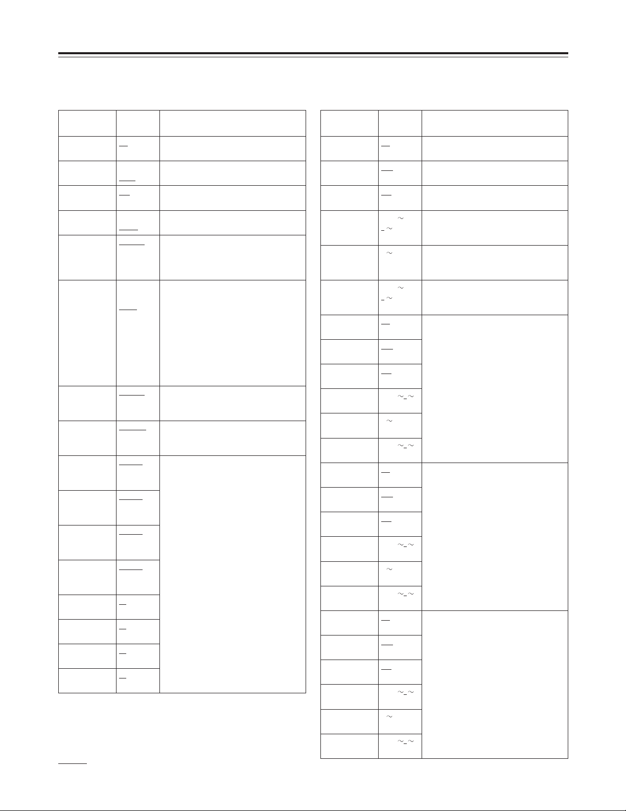
Parameter List
USER SET
Setting item Setting Remarks
Dropped Frame DF
NDF
Selects the frame mode in use.
Protocol Odetics
Louth
Selects the control protocol in use with
RS-422A.
FF.REW Max x32
, x64,
x128
Selects the speed for FF/REW.
SDTI Slow Audio Valid
Invalid
Selects audio data output for playback
at a1 speed or below.
Rec Start
Position
00:00:00
00:59:59
01:00:00
Selects the recording starting point
when recording instruction has been
given by operating the front panel
when creating a new CLIP.
Record Duration 10min
15min
30min
45min
1H
2H
4H
8H
Selects the recording time length of
CLIP ID used during loop recording (LREC).
<Note>
O
Upon writing over the existing CLIP
ID, loop recording takes place within
the length of recording time set from
the current position.
O
Loop recording operation takes
place only during STOP.
FTP Put Offset 00:00:00
00:59:59
01:00:00
Selects the recording starting point
when recording is done through
transmission from a non-linear system.
SDTI Illegal Input Rec Stop
Continue
Selects operation when SDTI signal
has detected no signal during
recording.
Ch1 Default Rate 25Mbps
50Mbps
100Mbps
Selects the format of signals used in
each channel.
However, the upper limit of maximum
usable stream count (25 Mbps mode
taken as 1) that has been set cannot
be exceeded.
For details, consult your dealer.
Ch2 Default Rate 25Mbps
50Mbps
100Mbps
Ch3 Default Rate 25Mbps
50Mbps
100Mbps
Ch4 Default Rate 25Mbps
50Mbps
100Mbps
Ch1 Default
Times
x1, x2, x4
Ch2 Default
Times
x1, x2, x4
Ch3 Default
Times
x1, x2, x4
Ch4 Default
Times
x1, x2, x4
A/S SET
Setting item Setting Remarks
CH1 CF Enable On
Off
Selects channel 1 color frame control.
CH1 VOUT
SetUp
Add
Thru
Selects setup level during channel 1
playback.
CH1 VIN SetUp Cut
Thru
Selects setup level during channel 1
recording.
CH1 SYS H
–121
0
+120
Performs rough tuning of channel 1
system phase in relation to standard
signal. (37ns step)
CH1 SYS SC
0
1023
Performs fine tuning of channel 1
system phase in relation to standard
signal. (0.35° step)
CH1 SCH
–128
0
+127
Performs tuning of channel 1 SC-H
(Subcarrier to Horizontal) phase.
(1.41° step)
CH2 CF Enable On
Off
Channel 2 setting is the same as for
channel 1.
CH2 VOUT
SetUp
Add
Thru
CH2 VIN SetUp Cut
Thru
CH2 SYSH
–121
0
+120
CH2 SYS SC
0
1023
CH2 SCH
–128
0
+127
CH3 CF Enable On
Off
Channel 3 setting is the same as for
channel 1.
CH3 VOUT
SetUp
Add
Thru
CH3 VIN SetUp Cut
Thru
CH3 SYSH
–121
0
+120
CH3 SYS SC
0
1023
CH3 SCH
–128
0
+127
CH4 CF Enable On
Off
Channel 4 setting is the same as for
channel 1.
CH4 VOUT
SetUp
Add
Thru
CH4 VIN SetUp Cut
Thru
CH4 SYSH
–121
0
+120
CH4 SYS SC
0
1023
CH4 SCH
–128
0
+127
indicates factory setting mode.
Page 24

CCHH11 CCLLIIPP00000011 0000::0000::0000::0000 ((CCTTLL11)) RREEWW
SSeerrvveerr SSoofftt::VVxx..xxxx..xxxx FF55::MMAAIINN
44
Press the [F5] button to return to main screen pattern 1.
Information displayed:
Server Soft:Vx.xx.xx
Raid Board :Vx.xx.xx
Fpc Soft :Vx.xx.xx
DVCPCI Soft:Vx.xx.xx
ISIO :Vx.xx.xx
SDTI IF :Vx.xx.xx
CH1 Board :Vx.xx.xx
CH2 Board :Vx.xx.xx
CH3 Board :Vx.xx.xx
CH4 Board :Vx.xx.xx
$
Version Display Screen
Displays the version of software for the server or front
panel controller, etc.
Data on each version is switched by cursor button [#]
or [2].
24
Display Panel
0000//0055//1199 1122::2244::4433 DDIISSKK FFUULLLL
FF11::SSIILLEENNTT--MMOODDEE FF33::BBUUZZZZEERR--OOFFFF FF55::BBAACCKK
1
234
1
Error content display
Error contents are displayed.
Display is made in the following format: year,
month, day, hour, minute, second and error
contents.
2
[F1] SILENT-MODE
When the [F1] button is pressed, the SILENTMODE is assumed and even if an error occurs, the
error display screen is not shown.
Display is restored by establishing ATTN-MODE
with the error log display screen.
3
[F3] BUZZER-OFF
When the [F3] button is pressed, the alarm stops.
4
[F5] BACK
When the [F5] button is pressed, the screen shown
prior to the error display screen is restored.
$
Error Display Screen
When an error has occurred in the server, it is
displayed.
Page 25

$
CLIP Display Screen
Shows the CLIP in storage.
25
Display Panel
EERRAASSEE CCLLIIPP:: CCLLIIPP00000011
SSEETT oorr CCAANNCCEELL
1
1
CLIP name display
The CLIP name selected by the CLIP display
screen is shown.
When the [SET] button is pressed, the CLIP shown at
1
is erased.
When erasure is completed, the CLIP display screen
is restored and the next CLIP is shown.
If erasure cannot be completed, ERASE FAILURE is
shown and the CLIP erase screen remains as is.
Press the [CANCEL] button to return to CLIP display
screen.
$
CLIP Erase Screen
Erases the CLIP on display.
22// 1144 CCLLIIPP00000011 2255MMbbppss
33
FF11::EERRAASSEE FF22::RREENNAAMMEE FF33::DDEETTAAIILL FF55::MMAAIINN
44
2318
7
45 6 9
SSTTAARRTT 0000::0000::0000::0000 ((0044::0000::0000::0011)) 2255MMbbppss
FF11::EERRAASSEE FF22::RREENNAAMMEE FF33::DDEETTAAIILL FF55::MMAAIINN
44
1
File number display
Displays the number of registered CLIPS and the
order of CLIPS to be displayed.
2
CLIP name display
Displays the CLIP name.
3
Recording format display
Displays the recording format of the CLIP
displayed.
4
[F1] ERASE
Press the [F1] button to erase CLIP.
When the [F1] button is pressed, the CLIP erase
screen is called up.
5
[F2] RENAME
Press the [F2] button to change the name of the
CLIP.
When the [F2] button is pressed, the CLIP name
change screen is called up.
6
[F3] DETAIL
When the [F3] button is pressed, information on the
CLIP displayed is shown for two seconds.
The following three types of information are
displayed.
Start time code
Material duration
Recording format
7
[F5] MAIN
Press the [F5] button to return to main screen
pattern 1.
8
Previous CLIP display
Shows that there is a CLIP to display.
When cursor button [#] is pressed, the previous
CLIP is displayed.
9
Next CLIP display
Shows that there is a CLIP to display.
When cursor button [2] is pressed, the next CLIP is
displayed.
RREENNAAMMEE CCLLIIPP:: CCLLIIPP00000011
33
FF33::DDEELL SSEETT oorr CCAANNCCEELL
44
1
Cursor
2
1
CLIP name display
The CLIP name selected by CLIP display screen is
shown.
With cursor button [!] [1], select the characters to
be changed; change the characters with cursor
button [#] [2]. Characters are shown in the
sequence: A ~ Z, a ~ z, 0 ~ 9, -, $, %.
Up to 8 characters can be input.
2
[F3] DEL
When the [F3] button is pressed while inputting
characters, the character at the cursor position is
deleted, and subsequent characters fill in the gap.
When the [SET] button is pressed, the CLIP name is
changed.
When name change is completed, the CLIP display
screen is restored and the next CLIP is shown.
If name change cannot be completed, RENAME
FAILURE is shown and the CLIP rename screen
remains as is.
Press the [CANCEL] button to return to CLIP display
screen.
$
CLIP Rename Screen
Changes the name of the CLIP on display.
Page 26

26
$
Simplified Manual Operation
Screen
Facilitates simplified manual operation of the unit.
The upper register has the same display as the main
screen. The screen for simplified manual operation is
shown in the lower register.
<Note>
Perform simplified manual operations after switching
the relevant channel to local mode at main screen.
Display Panel
CCHH11 CCLLIIPP00000011 0000::0000::0000::0000 ((CCTTLL)) RREEWW
FF11::LLOOAADD FF22::CCUUEE FF33::PPLLAAYY FF44::SSTTOOPP FF55::MMAAIINN
44
Simplified Manual Operation Screen Pattern 1
12 3 4 5
6879:
CCHH11 CCLLIIPP00000011 0000::0000::0000::0000 ((CCTTLL)) RREEWW
33
FF11::LLOOAADD FF22::CCUUEE FF33::RREECC FF44::SSTTOOPP FF55::MMAAIINN
44
Simplified Manual Operation Screen Pattern 2
12 3 4 5 <
67 9=:;
;
CCHH11 CCLLIIPP00000011 0000::0000::0000::0000 ((CCTTLL)) RREEWW
33
FF11::RREEWW FF22::FFFF FF33::PPLLAAYY FF44::SSTTOOPP FF55::MMAAIINN
44
Simplified Manual Operation Screen Pattern 3
12 3 4 5 <
>? 98:;
CCHH11 CCLLIIPP00000011 0000::0000::0000::0000 ((CCTTLL)) RREEWW
33
FF11::LL--PPLLAAYY FF22::LL--RREECC FF44::EEJJEECCTT FF55::MMAAIINN
Simplified Manual Operation Screen Pattern 4
12 3 4 5 <
@A B:
Displays common to the 4 patterns
The contents from 1to 1are the same as for the
main screen.
:
[F5] MAIN
When the [F5] button is pressed, main screen
pattern 1 is restored.
;
Next pattern display
Shows that there is a screen pattern to display.
When cursor button [2] is pressed, the next screen
pattern is displayed.
Example:
When currently at pattern 1, the change is from
pattern 1 to pattern 2 to pattern 3 to pattern 4.
<
Previous pattern display
Shows that there is a screen pattern to display.
When cursor button [#] is pressed, the previous
screen pattern is displayed.
Example:
When currently at pattern 4, the change is from
pattern 4 to pattern 3 to pattern 2 to pattern 1.
Page 27

27
Display Panel
Simplified Manual Operation Screen
Pattern 2
6
[F1] LOAD
When the [F1] button is pressed, the CLIP load
screen is shown.
See the CLIP load screen for details.
7
[F2] CUE
When the [F2] button is pressed, the CLIP currently
being loaded is queued up again.
=
[F3] REC
When the [F3] button is pressed, input signal to the
relevant channel is recorded in the CLIP currently
being loaded from the current position.
9
[F4] STOP
When the [F4] button is pressed, the CLIP currently
being loaded is stopped.
Simplified Manual Operation Screen
Pattern 3
>
[F1] REW
When the [F1] button is pressed, the CLIP currently
being loaded is rewound.
?
[F2] FF
When the [F2] button is pressed, the CLIP currently
being loaded is fast forwarded.
9
[F4] STOP
When the [F4] button is pressed, the CLIP currently
being loaded is stopped.
Simplified Manual Operation Screen
Pattern 4
@
[F1] L-PLAY
When the [F1] button is pressed, the CLIP currently
being loaded is played back repeatedly.
A
[F2] L-REC
When the [F2] button is pressed, recording takes
place repeatedly in the CLIP currently being loaded
for the time set by Record Duration in the
parameter setting screen.
B
[F4] EJECT
When the [F4] button is pressed, the CLIP assumes
unloaded status and the display of 2Selection
CLIP becomes “DEFAULT.”
Simplified Manual Operation Screen
Pattern 1
6
[F1] LOAD
When the [F1] button is pressed, the CLIP load
screen is shown.
See the CLIP load screen for details.
7
[F2] CUE
When the [F2] button is pressed, the CLIP currently
being loaded is queued up again.
8
[F3] PLAY
When the [F3] button is pressed, the CLIP currently
being loaded is played back.
9
[F4] STOP
When the [F4] button is pressed, the CLIP currently
being loaded is stopped.
Page 28

28
Display Panel
1
File number display
Displays the number of registered CLIPS and the
order of CLIPS to be displayed.
2
Channel display
Displays the channel number to be loaded.
3
CLIP name display
Displays the CLIP name.
4
Recording format display
Displays the recording format of the CLIP
displayed.
5
[F1] LOAD
When the [F1] button is pressed, the CLIP on
display is loaded into the current display channel
and simplified manual operation menu pattern 1 is
restored.
6
[F2] NEW
Press the [F2] button to create a new CLIP.
When the [F2] button is pressed, the CLIP creation
screen is called up.
7
[F3] DETAIL
When the [F3] button is pressed, information on the
CLIP displayed is shown for two seconds.
The following three types of information are
displayed.
Start time code
Material duration
Recording format
8
[F5] BACK
Press the [F5] button to return to simplified manual
operation screen pattern 1.
9
Previous CLIP display
Shows that there is a CLIP to display.
When cursor button [#] is pressed, the previous
CLIP is displayed.
:
Next CLIP display
Shows that there is a CLIP to display.
When cursor button [2] is pressed, the next CLIP is
displayed.
$
CLIP Load Screen
Shows the CLIP in storage.
NNEEWW CCLLIIPP::CCLLIIPP00000011
33
FF33::DDEELL SSEETT oorr CCAANNCCEELL
44
1
2
1
CLIP name display
The new CLIP name is shown.
With cursor button [!] [1], select the characters to
be changed; change the characters with cursor
button [#] [2]. Characters are shown in the
sequence: A ~ Z, a ~ z, 0 ~ 9, -, $, %.
Up to 8 characters can be input.
2
[F3] DEL
When the [F3] button is pressed while inputting
characters, the character at the cursor position is
deleted, and subsequent characters fill in the gap.
When the [SET] button is pressed, the created CLIP is
loaded into the current display channel and simplified
manual operation screen pattern 1 is restored.
Press the [CANCEL] button to return to simplified
manual operation screen pattern 1.
$
CLIP Creation Menu
Creates a new CLIP.
22// 1144 CCHH11::CCLLIIPP00000011 2255MMbbppss
33
FF11::LLOOAADD FF22::NNEEWW FF33::DDEETTAAIILL FF55::BBAACCKK
44
34219
567 8:
Page 29

29
Display Panel
SS11 SS22 11 22 33 44 55 66 77 88 PP RREEBBUUIILLDD
33
::
FF55::MMAAIINN
12
Press cursor button [!] [1] to select the HDD to be
reconstructed. When the cursor button [!] [1] is
pressed, the arrow at 1moves.
Reconstruction of the selected HDD begins when the
[SET] button has been pressed after selection of the
HDD.
<Note>
Do not execute this operation while another HDD is
being reconstructed.
Press the [CANCEL] button to abort reconstruction
and return to the HDD status display screen.
2
[F5] MAIN
Press the [F5] button to return to main screen
pattern 1.
3 3
When the cursor button [#] is pressed, the HDD
status display screen is restored.
$
HDD Reconstruction Selection
Screen
Reconstructs the HDD.
SS11 SS22 11 22 33 44 55 66 77 88 PP SSTTAATTUUSS
33
OOKK OOKK OOKK OOKK OOKK OOKK OOKK OOKK OOKK OOKK OOKK FF55::MMAAIINN
12
3
3
<Note>
S1 and S2 apply to SYS1 HDD and SYS2 HDD,
respectively.
1
HDD status display
Each HDD status is displayed.
OK: Operating normally
NG: Not operating normally
RE: Data are being reconstructed.
2
[F5] MAIN
Press the [F5] button to return to main screen
pattern 1.
3 3
When the cursor button [#] is pressed, the
reconstruction selection screen is called up.
$
HDD Status Display Screen
Displays HDD status.
When there are 8 HDDs for data
When there are 8 HDDs for data
SS11 SS22 11 22 33 44 PP RREEBBUUIILLDD
33
::
FF55::MMAAIINN
12
SS11 SS22 11 22 33 44 PP SSTTAATTUUSS
33
OOKK OOKK OOKK OOKK OOKK OOKK OOKK FF55::MMAAIINN
12
3
3
When there are 4 HDDs for data
When there are 4 HDDs for data
Page 30

30
Display Panel
1
Error content display
Error contents are displayed.
Display is made in the following format: year,
month, day, hour, minute, second and error
contents.
2
[F1] SILENT-MODE
When the [F1] button is pressed, change is made
between SILENT-MODE and ATTN-MODE.
In SILENT-MODE, even if an error occurs, the error
display screen is not shown.
In ATTN-MODE, if an error occurs, the error display
screen is shown.
3
[F3] DETAIL
When the [F3] button is pressed, the error log
detailed display screen is called up.
4
[F5] MAIN
When the [F5] button is pressed, display returns to
main screen pattern 1.
5
Previous error log display
Shows that there is an error log to display.
When cursor button [#] is pressed, the previous
error log is displayed.
6
Next error log display
Shows that there is an error log to display.
When cursor button [2] is pressed, the next error
log is displayed.
$
Error Log Display Screen
Displays error log. Up too 100 errors stored.
0000//0055//1199 1122::2244::4433 DDIISSKK FFUULLLL
33
FF11::SSIILLEENNTT--MMOODDEE FF33::DDEETTAAIILL FF55::MMAAIINN
44
15
6
234
((XXXX)) FFaann//TTeemmpp.. EErrrroorr
((1100--0000--00111100--22000011--00000011)) FF55::MMAAIINN
44
1
Error generation point display
Shows where an error has been generated.
2
Error number display
Error is shown by number.
Display is in the following format: error type,
channel number, error generation point, error
content, optional data.
<Note>
Data on numbers for error type
10: Shown when running cannot be continued or
when operations are abnormal.
Consult your dealer immediately.
11: Running can be continued.
Remove the cause of the warning generation.
20: Running can be continued.
Shows internal processing data.
$
Error Log Detailed Display Screen
Shows details of the error log.
Error log generation point
Error (number)
FF55::BBAACCKK
1
23
3
[F5] BACK
Press the [F5] button to return to error log display
screen.
Display examples:
O
Abnormal heat discharge fan
((XXXX)) IIDD MMaaxxNNuumm.. EErrrroorr
((1100--0000--00331100--11330055--00000000)) FF55::MMAAIINN
44
O
Recording not possible because ID maximum
number has been exceeded.
((XXXX)) OOppttiioonn BBooaarrdd SSeeaarrcchh
((2200--0000--00110000--22110000--00000011)) FF55::MMAAIINN
44
O
Assessment of input/output boards is complete.
((XXXX)) FF..PPaanneell SSeell.. LLooccaall
((1111--0000--00110066--22770000--00000000)) FF55::MMAAIINN
44
O
Cannot control from external controller because
control is in local mode.
Page 31

31
F3 (CH4)
F3 (CH3)
F3 (CH2)
F3 (CH1)
Always be sure the power cord is removed
before installing the optional board.
Optional Board Installation
1. Remove the two coin screws securing the unit’s top
panel. Remove the top panel.
2. Remove the three screws holding down the circuit
board securing fittings, then remove the fittings.
Unplug the two SDTI flat cables from the IF board.
<Note>
Be sure to note the connector locations so you can
reconnect them properly when reassembling the
unit later.
3. Connect the connector panel (packed together with
the optional board) to the optional board.
4. Connect the unit’s rear panel connector and the
optional board. Insert the optional board into the
unit.
<Note>
Confirm that the rear panel connector channel
matches the channel of the slot into which the
optional board is inserted.
5. Reconnect the two SDTI flat cables to the IF board.
<Note>
Make sure the cables are plugged in at the correct
locations.
6. Remount the circuit board securing fittings with the
three screws and reattach the top panel.
<Note>
Be sure to secure the top panel in place using the
coin screws.
SDTI flat cables
Circuit board
securing fittings
screws
screw
Four optional boards are available.
1. Analog I/O board (AJ-YA7000P)
2. Analog out board (AJ-YA7200P)
3. SDTI I/O board (AJ-YAC7000P)
4. SDI I/O board (AJ-YA7100P)
(The analog out board is required for the SDI I/O
board.)
The above four boards can be installed for any or all
of the four channels. The installation locations are
described below.
Attach the connectors for connection with the rear
panel to the slots marked “F3” on the AV block, and
then insert the boards.
The number and types of connectors differs
depending on the type of board concerned.
Consult your dealer for details on setting and
installing the optional boards.
Optional Board Installation Method
Page 32

32
1. Analog I/O board
(AJ-YA7000P)
Proceed with the connections in the sequence
described below.
SW1 setting
(for input audio signals with 600-ohm termination) (CH1)
ON: 600-ohm termination OFF: High impedance
SW2 setting
(for input audio signals with 600-ohm termination) (CH2)
ON: 600-ohm termination OFF: High impedance
SW3 setting
For the NTSC system (factory setting)
5: OFF 6: ON 7: OFF 8: ON
For the PAL system (setting must be changed)
5: ON 6: OFF 7: ON 8: OFF
Input audio level selection
1234
+4 dBu ON OFF ON OFF
0 dBu OFF ON OFF ON
–20 dBu ON ON ON ON
SW5 setting
Output audio level selection
1234
+4 dBu OFF OFF OFF OFF
0 dBu ON OFF ON OFF
–20 dBu OFF ON OFF ON
SW9 setting
ON for all switches
Optional Board Installation Method
ANALOG DIGITAL
VIDEO
IN
OUT
OUT
SDI/SDTI
IN
REMOTE INAUDIO OUTAUDIO IN
AUDIO IN AUDIO OUT
VIDEO OUT
SW 5
SW 3
SW 1 SW 2
SW 9
VIDEO
THROUGH
VIDEO
IN
Analog in board
Analog out board
Rear panel connectors
(designated channel)
Position where terminal resistance is
mounted (No automatic termination.)
Black
Red
Orange
Analog audio panel
(packed together with optional board)
1. Remove the four screws, and remove the analog in
board from analog out board.
2. Connect the cables (for composite signals a3) from
the unit to the analog in board.
3. Orient the analog out board and analog in board so
that the sides on which components are mounted
are facing each other. Place spacers between
them, and attach them together with four screws in
the four places indicated.
4. Install the analog I/O board in the server.
Perform the connections as illustrated below.
Page 33

33
2. Analog out board
(AJ-YA7200P)
Perform the connections as illustrated below.
Optional Board Installation Method
ANALOG DIGITAL
VIDEO
IN
OUT
OUT
SDI/SDTI
IN
REMOTE INAUDIO OUT
AUDIO OUT
VIDEO OUT
SW 5
SW 3
SW 1 SW 2
SW 9
VIDEO THROUGH
VIDEO IN
Analog out board
Rear panel connectors
(designated channel)
Black
Red
Orange
Analog audio out panel
(packed together with optional board)
SW1 setting
(for input audio signals with 600-ohm termination) (CH1)
ON: 600-ohm termination OFF: High impedance
SW2 setting
(for input audio signals with 600-ohm termination) (CH2)
ON: 600-ohm termination OFF: High impedance
SW3 setting
For the NTSC system (factory setting)
5: OFF 6: ON 7: OFF 8: ON
For the PAL system (setting must be changed)
5: ON 6: OFF 7: ON 8: OFF
Input audio level selection
1234
+4 dBu ON OFF ON OFF
0 dBu OFF ON OFF ON
–20 dBu ON ON ON ON
SW5 setting
Output audio level selection
1234
+4 dBu OFF OFF OFF OFF
0 dBu ON OFF ON OFF
–20 dBu OFF ON OFF ON
SW9 setting
ON for all switches
Page 34

34
3. SDTI I/O board
(AJ-YAC7000P)
Perform the connections as illustrated below.
Optional Board Installation Method
S-OUT 3
ANALOG DIGITAL
VIDEO
IN
OUT
OUT
SDI/SDTI
IN
REMOTE IN
S-OUT 1
S-OUT 2
S-IN
S-IN THROUGH
SDTI I/O board
Rear panel connectors
(designated channel)
Black
Red
Orange
SDTI cover
(packed together with optional board)
Page 35

35
S-IN S-IN THROUGH S-OUT
ANALOG DIGITAL
VIDEO
IN
OUT
OUT
SDI/SDTI
IN
REMOTE INAUDIO OUTVIDEO OUT
AUDIO OUT
VIDEO OUT
Analog out board
Rear panel connectors
(designated channel)
4. SDI I/O board
(AJ-YA7100P)
Proceed with the connections in the sequence
described below.
1. Connect the cables (for SDI signals a3) from the
unit to the SDI I/O board.
2. Connect the coaxial cables (for video signals a1,
for audio signals a1) packed with the SDI I/O board
to the analog out board.
3. Orient the SDI I/O board and analog out board so
that the sides on which components are mounted
are facing each other. Place spacers between
them, and attach them together with a total of eight
screws in the four places indicated.
4. Install the SDI I/O board and analog out board in
the server.
Perform the connections as illustrated below.
SDI I/O board
Optional Board Installation Method
Black
Red
Orange
Analog out panel
(packed together with optional board)
Page 36

36
<Warning>
O
The optional HDD (AJ-HDD36P) is exclusively for the unit (AJ-HDR150).
Do not use it for any other applications.
If any damages should arise as a result of use for other applications, the Company cannot assume any
responsibility or warranty.
O
To install the optional HDD, consult your dealer.
Optional HDD
Coin screw
Coin screw
Page 37

37
Symptom
$
Server’s power LED fails to light
even when the power switch is ON.
Suggested remedial action
O
Has the power cord been connected?
O
Do the installed fuses have the rated amperage?
$
No display on the display panel
even though the power switch is
on.
$
The buzzer continues to sound
after the operation LED has lighted.
O
Something has malfunctioned.
Check on the display panel.
$
No control can be exercised using
RS-422A.
O
Have the cables been connected properly?
O
Is the server mode set to LOCAL?
Check on the display panel.
$
There is no sound.
O
Are the cables connected properly?
O
There is no audio output during playback at speeds lower than 1
a
speed.
$
Video recording stops at an interim
point.
O
Is there space on the HDD?
Check remaining time on the display panel or using Odetics/Louth
protocol.
O
Is access to the HDD delayed?
O
Is there anything wrong with the input signal?
O
Is FC cable connected properly?
Troubleshooting
O
Has the power been turned back on immediately after it was turned
off?
Wait at least 10 seconds after turning off the power before turning it
back on.
Page 38

38
$
REF VIDEO IN
BNCa2, loop-through with 75 Ω termination switch
Connector Signals
$
SVGA-I/F (for maintenance)
Pin No. Signal
1 CRV
2 CGV
3 CBV
4
___
5 8 GND
9
___
10 GND
11
___
12 DCI Comm
13 – CHSYNC
14 – CVSYNC
15
___
$
RS-232C (for maintenance)
Pin No. Signal
1CD
2 RXD
3 TXD
4DTR
5 GND
6 DSR
7 RTS
8 CTS
9CI
$
Mouse/Keyboard (for maintenance)
Pin No. Signal
1 DATA
2
___
3 GND
4 +5 V
5 CLOCK
6
___
$
RS-422A (REMOTE IN)
Pin No. Signal
1 GND
2 RXD –
3 TXD +
4 GND
5 spare
6 GND
7 RXD +
8 TXD –
9 GND
$
Fibre Channel (HOST/RAID)
Pin No. Signal
1 TX +
2
___
3
___
4
___
5 RX +
6 TX –
7
___
8
___
9 RX –
$
LAN (for system expansion)
Pin No. Signal
1 TX +
2 TX –
3 RX +
4
___
5
___
6 RX –
7
___
8
___
Maintenance terminals are used by service
personnel for maintenance.
Customers are asked to never connect these
terminals.
Page 39

39
Connector Signals
$
Analog I/O board
VIDEO IN:
BNCa2, loop-through with 75-ohm termination
switch
(This board does not support non-standard
signals.)
VIDEO OUT:
BNCa1
(The EE output is not locked to the REF input.)
AUDIO IN (ANALOG):
XLRa2, CH1/CH2
AUDIO OUT (ANALOG):
XLRa2, CH1/CH2
$
Analog out board
VIDEO OUT:
BNCa1
AUDIO OUT (ANALOG):
XLRa2, CH1/CH2
$
SDTI I/O board
SDTI IN:
BNCa2, with buffer out
Complies with SMPTE305M standard
SDTI OUT:
BNCa1
Complies with SMPTE305M standard
(The EE output is not locked to the REF input.)
Data stream format:
Complies with the SMPTE321M standard
$
SDI I/O board (+ analog out board)
SDI IN:
BNCa2, with buffer out
Complies with SMPTE259M-C and 272M
standard
SDI OUT:
BNCa1
Complies with SMPTE259M-C and 272M
standard
(The EE output is not locked to the REF input.)
VIDEO OUT (ANALOG):
BNCa1
(The EE output is not locked to the REF input.)
AUDIO OUT (ANALOG):
XLRa2, CH1/CH2
Page 40

40
[PC component]
[Control Component]
RS-422A:
4 channel (D-SUB, 9 pin)
RS-422A protocol:
Odetics/Louth
Playback response time:
At STBY ON:
0.5 sec or less (CUE UP completed)
At STBY OFF:
2 sec or less (prior to CUE UP)
RS-232C:
1 channel (for monitor, maintenance)
Alarms:
Fan alarm, HDD alarm, system alarm
Fibre Channel:
One port each for HOST and RAID
CPU:
Celeron, 433 MHz
OS:
Windows NT 4.0 (English version)
Memory:
128 MB
System HDD:
9 GB a2 units
Data HDD (Optional):
36 GB a9 units
Recording time:
20 hours (calculated at DVCPRO 25 Mbps)
Recording format:
DVCPRO 25 Mbps, DVCPRO 50 Mbps,
DVCPRO P, DVCPRO HD
Recording content:
Digital video, Time code (subcode domain), Digital
audio
CLIP count:
Maximum 5000
CLIP length:
1 second minimum
20 hours maximum (calculated at DVCPRO 25
Mbps)
Specifications
[GENERAL]
Power supply: 120 V ±10% AC, 50 – 60 Hz
Power consumption: 3.8 A
Ambient operating temperature:
41°F to 95°F (5°C to 35°C)
Ambient operating humidity:
10% to 80% (no condensation)
Dimensions (WaaHaaD):
16
3
/4˝a10 7/16˝a25 1/8˝ (424a265a637 mm)
Weight:
91.52 lb (41.6 kg)
With all optional devices installed: 105.6 lb (48 kg)
Page 41

41
Specifications
Sampling frequencies:
Y: 13.5 MHz, PB/PR: 3.375 MHz
Quantizing:
8 bits
[Option]
$
VIDEO
Digital
Video band:
Y: 30 Hz to 4.5 MHz (±1 dB)
Differential gain:
Less than 6%
Differential phase:
Less than 4.5 degrees
Y/C delay:
Less than 20 ns
K factor:
Less than 2%
Analog composite IN/OUT
Sampling frequencies:
48 kHz
Quantizing:
16 bits
$
AUDIO
Digital
Frequency response:
20 Hz to 20 kHz (+1 dB, –2dB)
Dynamic range:
More than 80 dB
(1 kHz, “A” weighted)
Distortion:
Less than 0.15%
(1 kHz, reference level)
Crosstalk:
Less than –74 dB
Headroom:
20 dB
Analog IN/OUT
Page 42

PANASONIC BROADCAST & TELEVISION SYSTEMS COMPANY
DIVISION OF MATSUSHITA ELECTRIC CORPORATION OF AMERICA
Executive Office:
3330 Cahuenga Blvd W., Los Angeles, CA 90068 (323) 436-3500
EASTERN ZONE:
One Panasonic Way 4E-7, Secaucus, NJ 07094 (201) 348-7621
Southeast Region:
1225 Northbrook Parkway, Ste 1-160, Suwanee, GA 30024 (770) 338-6835
Central Region:
1707 N Randall Road E1-C-1, Elgin, IL 60123 (847) 468-5200
WESTERN ZONE:
3330 Cahuenga Blvd W., Los Angeles, CA 90068 (323) 436-3500
Government Marketing Department:
52 West Gude Drive, Rockville, MD 20850 (301) 738-3840
Broadcast PARTS INFORMATION & ORDERING:
9:00 a.m. – 5:00 p.m. (EST) (800) 334-4881/24 Hr. Fax (800) 334-4880
Emergency after hour parts orders (800) 334-4881
TECHNICAL SUPPORT:
Emergency 24 Hour Service (800) 222-0741
Panasonic Canada Inc.
5770 Ambler Drive, Mississauga, Ontario L4W 2T3 (905) 624-5010
Panasonic de Mexico S.A. de C.V.
Av angel Urraza Num. 1209 Col. de Valle 03100 Mexico, D.F. (52) 1 951 2127
Panasonic Sales Company
Division of Matsushita Electric of Puerto Rico Inc.
San Gabriel Industrial Park, 65th Infantry Ave., Km. 9.5, Carolina, Puerto Rico 00630 (787) 750-4300
F1100W
@
Printed in Japan
VQT8955
P
Page 43

documentation manual, user maintenance, brochure, user reference, pdf manual
This file has been downloaded from:
User Manual and User Guide for many equipments like mobile phones, photo cameras, monther board, monitors, software, tv, dvd, and othes..
Manual users, user manuals, user guide manual, owners manual, instruction manual, manual owner, manual owner's, manual guide,
manual operation, operating manual, user's manual, operating instructions, manual operators, manual operator, manual product,
 Loading...