

Page 1
Operating Instructions
2K Processor
Model No. AJ-HDP2000P
Before operating this product, please read the instructions carefully and save this manual for future use.
F0707N0 -F @
Printed in Japan
ENGLISH
VQT1F04
Page 2
Read this first
!
_ DO NOT REMOVE PANEL COVERS BY
UNSCREWING THEM.
To reduce the risk of electric shock, do not remove
the covers. No user serviceable parts inside.
Refer servicing to qualified service personnel.
_ THIS EQUIPMENT MUST BE GROUNDED
To ensure safe operation, the three-pin plug must be
inserted only into a standard three-pin power outlet
which is effectively grounded through normal
household wiring. Extension cords used with the
equipment must have three cores and be correctly
wired to provide connection to the ground. Wrongly
wired extension cords are a major cause of fatalities.
The fact that the equipment operates satisfactorily
does not imply that the power outlet is grounded or
that the installation is completely safe.
For your safety, if you are in any doubt about the
effective grounding of the power outlet, please
consult a qualified electrician.
WARNING:
z TO REDUCE THE RISK OF FIRE OR SHOCK
HAZARD, DO NOT EXPOSE THIS
EQUIPMENT TO RAIN OR MOISTURE.
z TO REDUCE THE RISK OF FIRE OR SHOCK
HAZARD, KEEP THIS EQUIPMENT AWAY
FROM ALL LIQUIDS. USE AND STORE ONLY
IN LOCATIONS WHICH ARE NOT EXPOSED
TO THE RISK OF DRIPPING OR SPLASHING
LIQUIDS, AND DO NOT PLACE ANY LIQUID
CONTAINERS ON TOP OF THE EQUIPMENT.
CAUTION:
TO REDUCE THE RISK OF FIRE OR SHOCK
HAZARD AND ANNOYING INTERFERENCE,
USE THE RECOMMENDED ACCESSORIES
ONLY.
CAUTION:
TO REDUCE THE RISK OF FIRE OR SHOCK
HAZARD, REFER CHANGES OF SWITCH
SETTINGS INSIDE THE UNIT TO QUALIFIED
SERVICE PERSONNEL.
FCC Note:
This equipment has been tested and found to comply
with the limits for a class A digital device, pursuant to
Part 15 of the FCC Rules. These limits are designed to
provide reasonable protection against harmful
interference when the equipment is operated in a
commercial environment. This equipment generates,
uses, and can radiate radio frequency energy, and if not
installed and used in accordance with the instruction
manual, may cause harmful interference to radio
communications. Operation of this equipment in a
residential area is likely to cause harmful interference in
which case the user will be required to correct the
interference at his own expense.
Warning:
To assure continued FCC emission limit compliance, the
user must use only shielded interface cables when
connecting to external units. Also, any unauthorized
changes or modifications to this equipment could void
the user’s authority to operate it.
CAUTION:
The mains plug of the power supply cord shall
remain readily operable.
The AC receptacle (mains socket outlet) shall be
installed near the equipment and shall be easily
accessible. To completely disconnect this
equipment from the AC mains, disconnect the mains
plug from the AC receptacle.
CAUTION:
In order to maintain adequate ventilation, do not
install or place this unit in a bookcase, built-in
cabinet or any other confined space. To prevent risk
of electric shock or fire hazard due to overheating,
ensure that curtains and any other materials do not
obstruct the ventilation.
CAUTION:
z
KEEP THE TEMPERATURE INSIDE THE RACK
BETWEEN 41°F to 104°F (5°C to 40°C).
z BOLT THE RACK SECURELY TO THE FLOOR
SO THAT IT WILL NOT TOPPLE OVER WHEN
THE UNIT IS DRAWN OUT.
indicates safety information.
2
Page 3

Table of Content
s
Read this first! ............................................................................................... 2
Operating Precautions ................................................................................. 4
Overview/Features ........................................................................................ 5
1. Overviews ........................................................................................................5
2. Features ..........................................................................................................5
2.1. Compression .............................................................................................5
2.2. VTRs Migration .........................................................................................5
2.3. Dual-Link SDI & I/O ...................................................................................5
2.4. Maximum Record Time .............................................................................5
2.5. Indicator Display ........................................................................................5
2.6. Compact and Lightweight ..........................................................................5
Controls and their Functions ....................................................................... 6
1. Front Panel ......................................................................................................6
2. Connector Section (Rear) ................................................................................7
3. I/Os ..................................................................................................................8
3.1. VIDEO Input ..............................................................................................8
3.2. VIDEO Output ...........................................................................................8
3.3. AUDIO Input ..............................................................................................9
3.4. AUDIO Output ...........................................................................................9
3.5. TC (Time Code) Input ...............................................................................9
3.6. TC (Time Code) Output .............................................................................9
3.7. META DATA Input ...................................................................................10
3.8. META DATA Output ................................................................................10
3.9. Other I/Os (HD REF IN, VTR I/F) ............................................................10
3.10. Service Only (15 Pin) ..............................................................................10
2K Processor & HD-D5 VTR System Connections .................................. 11
Connection with existing systems ............................................................ 12
Indicator Display (Front Panel LED) .......................................................... 13
Connection Check ...................................................................................... 14
Service Switch (Rear) ................................................................................. 14
Power On ..................................................................................................... 14
Restrictions ................................................................................................. 15
Rack Mounting ............................................................................................17
Specifications .............................................................................................. 18
3
Page 4

Operating Precautions
_Power supply
Use an AC 120 V (U.S.A. and Canada) power supply.
z Be sure to take hold of the power plug when connecting and
disconnecting the power cable.
z Do not run the power cable near a heating source.
z Do not place heavy objects on top of the power cable.
z Do not tamper with the power cable in any way.
_No insertion of foreign matters
Do not insert or drop metal or any foreign objects into the unit’s
openings (such as the fan vents).
Foreign objects inside the unit can cause a fire or short circuits.
Contact the dealer for assistance.
_No disassembly
High voltage is supplied to some parts inside the unit, and
touching these parts is not only dangerous but may cause a
malfunction.
Leave all internal insections and adjustments to the dealer from
whom you purchased the unit.
_DANGER: No operation if unit is
malfunctioning
If smoke comes out or strange sounds or smells are detected
from the unit, ask the dealer from whom you purchased the unit
for repairs.
4
Page 5

Overview/Features
1. Overviews
This new 2K Processor (AJ-HDP2000) for the HD-D5 VTRs (AJ-HD3700H*1, AJ-HD3700A*1, AJ-HD3700B*2)
is designed for post-production and telecine systems, and this new technology provides a cost-effective and
efficient method of recording, editing and archiving full-size 2K and 4:4:4 HDTV images on the film postproduction standard D-5 mastering video tape recording system.
The 2K Processor allow professionals to record full 12-bit 4:4:4 “2K” 2048 k 1080 resolution film image data, or
12-bit 4:4:4 sampled 1920
HD-D5
VTRs for editing, archiving, and distribution, a process that formerly was not easily achievable.
*1The software must be upgraded. For details, contact the dealer where you purchased the product.
*2The software for some VTRs must be upgraded. For details, contact the dealer where you purchased the
product.
2. Features
k
1080 HD images onto Panasonic’s AJ-HD3700H, AJ-HD3700A or AJ-HD3700B
2.1. Compression
The 2K Processor uses JPEG2000 compression,
the similar compression scheme specified by the
Digital Cinema Initiative (DCI) for cinema release,
to convert film to digital data for subsequent
processing in advanced DI environments while
maintaining its resolution. The processor's
advanced encoder ensures that images remain
faithful throughout the recording process, and
minimizes distortion and resolution degradation
and offers optimized bit rate control and increased
error tolerance for the reliable interchange required
for editing.
2.2. VTRs Migration
The numerous Post facilities with capital
investments in D-5 will be able to use their current
AJ-HD3700 series, and the workflow that has
worked so well for them with existing HD-D5 VTRs
can be continued with a simple software upgrade
for 2K and HD post-production.
2.3. Dual-Link SDI & I/O
For ease of monitoring and interfacing with more
traditional high definition equipment, The 2K
Processor has added a 4:4:4 to 4:2:2 conversion
capability. The full audio capability of the D-5
format is maintained, including eight-channel 24-bit
recordings, as well as the ability of the system to
handle compression audio streams for multichannel / second language applications. Audio I/O
is by means of embedded HD-SDI or HD-D5 VTR’s
AES/EBU inputs, analog inputs. Interconnection
from the processor to the HD-D5 VTR is by
mapped compressed data over the HD-D5 VTR’s
existing HD-SDI input / outputs. The processor
accepts dual link SMPTE 372M video / 2K inputs.
Time Code in/out is embedded or HD-D5 VTR’s
XLR.
2.4. Maximum Record Time
Maximum recording time is 155 minutes, the same
as the HD-D5 VTR’s 24fps modes.
2.5. Indicator Display
Alarm indicator (RED):
When flashing, indicates that some errors
have occurred.
When lit constantly, indicates a serious
problem such as the fan has stopped or the
rear service switch is ON.
2048/1920 indicator (GREEN):
Indicates the Horizontal sample number of
System settings.
2.6. Compact and Lightweight
With a height of 2U and weight of 7.5 kg (16.5 lb),
this compact and lightweight unit can be
transported easily.
5
Page 6
Controls and their Functions
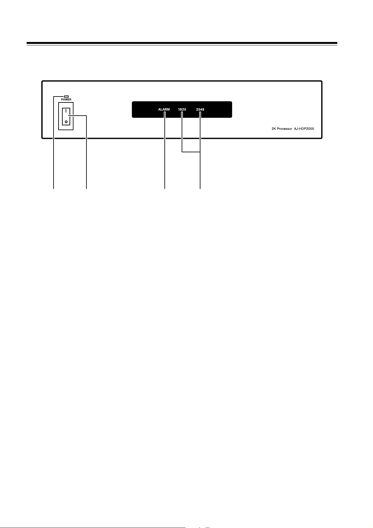
1. Front Panel
!2"!1" !3" !4"
!1" Power Lamp This lights when the power is turned on.
!2" Power Switch When the ON side is pressed, the power is turned on; when
the OFF side is pressed, the power is turned off.
| : Press the “ | ” side of the power switch to turn the power
on.
±: Press the “ ± ” side of the power switch to turn the power
off.
!3" Alarm Lamp This lights when a problem has occurred in the main unit,
making it impossible to guarantee operation. (Refer to the
messages on page 13.)
!4" Horizontal Sample Display Lamp This displays the H sample of the video signal that is system
setting.
6
Page 7

Controls and their Functions (Continued)
2. Connector Section (Rear)
!9"!8"!7"!6" !2"!11"!13"!12" !10" !1" !3"!4" !5"
!1" AC Input Socket Use the accessory power cord to connect the socket to the power outlet
!2" Fuse Power circuit fuse
!3" GND (ground) Terminal When connected with another unit, the unit must be ground here
!4" Dual-Link SDI Input For inputting the Dual-Link digital signals
!5" Dual-Link SDI Output 1, 2 For outputting the Dual-Link or HD digital signals
(4:4:4/4:2:2 switchable)
!6" HD-SDI Monitor Output For outputting the HD digital signals (4:2:2 samples)
!7" Serial Data input (HD-SDI) This is connected to the HD SDI OUT connector on the HD-D5 VTR for
inputting for video/ audio/ tc output data from the HD-D5 VTR.
!8" Serial Data Output (HD-SDI) This is connected to the HD SDI IN connector on the HD-D5 VTR for
outputting the video/ audio/ tc data.
!9" HD SYNC OUT This is connected to the REF IN HD connector on the HD-D5 VTR.
The sync signal re-generated from the HD REF IN signal of the
processor.
!10" HD REF IN For inputting the tri-level sync signals as reference signals
!11" HD Reference Through Output
(Auto Terminated)
!12" Service Switch
(only Use Service Maintenance)
!13" SERVICE ONLY (RS-232C)
<15pin>
(only Use Service Maintenance)
This is through output of input reference signal
This slide switch is used only in service mode.
Please Slide OFF for Normal Operation.
This connector is used only in service mode.
7
Page 8

Controls and their Functions (Continued)
3. I/Os
3.1. VIDEO Input
Name Video Input Signal
INPUT A
INPUT B
Dual Link SDI Input BNC a 2, 75 Ω
1920 a 1080/23.98, 24PsF XYZ/RGB 4:4:4
SMPTE 372M/291M/292M/299M standard
2048 a 1080/23.98, 24PsF XYZ/RGB 4:4:4
z The following two VIDEO input signals are supported.
1920 a 1080/23.98PsF, 24PsF XYZ/RGB 4:4:4 12 bits
2048
a 1080/23.98PsF, 24PsF XYZ/RGB 4:4:4 12 bits
z The color space signal format is selected from the following two types in FRONT MENU of the HD-D5 VTR.
SYSTEM settings for the RGB and XYZ color spaces
RGB: Mode for recording and playback RGB color space
XYZ: Mode for recording and playback XYZ color space
3.2. VIDEO Output
Name Video Output Signal
OUTPUT 1A
OUTPUT 1B
OUTPUT 2A
OUTPUT 2B
OUTPUT MON Single HD SDI Monitor Output BNC a 1, 75 Ω (Super ON/OFF)
Dual Link SDI Output BNC a 2 a 2, 75 Ω
1920 a 1080/23.98, 24PsF XYZ/RGB 4:4:4
SMPTE 372M/291M/292M/299M standard
2048 a 1080/23.98, 24PsF XYZ/RGB 4:4:4
1920 a 1080/23.98, 24PsF YPbPr 4:2:2
SMPTE 291M/292M/299M standard
1920 a 1080/23.98, 24PsF YPbPr 4:2:2
SMPTE 292M standard
(Video Signal only w/o ANC data)
z There are three types of VIDEO output signals, and output signals are set in SYSTEM FORMAT in FRONT
MENU of the HD-D5 VTR.
1920
a 1080/23.98PsF, 24PsF XYZ/RGB 4:4:4 12/10 bits
a 1080/23.98PsF, 24PsF XYZ/RGB 4:4:4 12/10 bits
2048
1920
a 1080/23.98PsF, 24PsF YPbPr 4:2:2 10 bits
z The main output is available in 4:2:2 format
a 4 lines.
z Both main output and monitor output have the Dynamic Rounding function when 10-bit output is selected.
z The VANC/HANC data, such as Audio/TC/Meta/Payload information, is not embedded on the OUTPUT MON
(Monitor) output.
z In OUTPUT MON (Monitor) and when the 4:2:2 format is selected for the main system, an H CROP function for
1920 samples is available in 2048 samples. However, the Squeeze and Letter Box functions are not available.
The following three kinds of modes are available as fixed Crop modes.
CTR Crop: Both sides are equally cropped so that the number of samples is 1920.
L Crop: The left side is cropped so that the number of samples is 1920.
R Crop: The right side is cropped so that the number of samples is 1920.
z OUTPUT MON (Monitor) has a function to turn on/off superimposition in SUPER.
8
Page 9

Controls and their Functions (Continued)
3.3. AUDIO Input
Audio Input Signal
Dual Link SDI Input
(Embedded Audio)
z For AUDIO input, an SDI Embedded Audio function is available with the 2K processor, and AES/EBU Digital
Audio, Analog Audio, and CUE Audio inputs are available from the HD-D5 VTR in a manner similar to the single
operation of the HD-D5 VTR.
z The AUDIO input signal is selected in FRONT MENU of the main unit in a manner similar to the single
operation of the HD-D5 VTR.
z SDI Embedded Audio input signals are available only for Ach of Dual Link SDI signals.
BNC a 2, 75 Ω
SMPTE 299M standard
3.4. AUDIO Output
Audio Output Signal
Dual Link SDI Output
(Embedded Audio)
z For AUDIO output, an SDI Embedded Audio function is available with the 2K processor, and AES/EBU Digital
Audio, Analog Audio, and CUE Audio outputs are available from the HD-D5 VTR in a manner similar to the
single operation of the HD-D5 VTR.
z The AUDIO output signal is selected in FRONT MENU of the HD-D5 VTR in a manner similar to the single
operation of the HD-D5 VTR.
z SDI Embedded Audio output signals are available only on Ach of Dual Link SDI signals.
z SDI Embedded Audio signals are not available on OUTPUT MON (Monitor).
BNC a 2 a 2, 75 Ω
SMPTE 299M standard
3.5. TC (Time Code) Input
TC Input Signal
Dual Link SDI Input
(Embedded LTC/VITC)
z For TC input, an SDI Embedded HANC TC function is available with the 2K processor, and the LINEAR TC
input is available from the HD-D5 VTR in a manner similar to the single operation of the HD-D5 VTR.
z For SDI Embedded HANC TC input signals, only Ach of Dual Link SDI signals is supported.
z LTC or VITC can be selected as a SDI Embedded HANC TC input signal.
z The TC input signal is selected in FRONT MENU of the HD-D5 VTR in a manner similar to the single operation
of the HD-D5 VTR.
BNC a 2, 75 Ω
SMPTE 291M standard
3.6. TC (Time Code) Output
TC Output Signal
Dual Link SDI Output
(Embedded LTC/VITC)
z For the TC output, an SDI Embedded HANC TC function is available with the 2K processor, and the LINEAR
TC output is available from the HD-D5 VTR in a manner similar to the single operation of the HD-D5 VTR.
z SDI Embedded HANC TC output signals are available only on Ach of Dual Link SDI signals.
z SDI Embedded HANC TC signals are not available on the OUTPUT MON (Monitor).
BNC a 2 a 2, 75 Ω
SMPTE 291M standard
9
Page 10

Controls and their Functions (Continued)
3.7. META DATA Input
z For META DATA input, an SDI Embedded VANC function is available with the 2K processor, only Y signals in
Ach of Dual Link SDI signals are supported.
z META DATA can record up to 2,880 words per segmented frame.
The capacity of 2,880 words is the upper limit even when data exceeds the capacity (the same as single
operation of the HD-D5 VTR in the specifications).
3.8. META DATA Output
z For META DATA output, an SDI Embedded VANC function is available with the 2K processor, and META DATA
signals are embedded only on Y signals in Ach of Dual Link SDI signals.
z META DATA output is embedded up to 2,880 words per segment frame on Y signals, where data is entered
from the head (the same as single operation of the HD-D5 VTR in specification).
z META DATA signals are not embedded on the OUTPUT MON (Monitor).
3.9. Other I/Os (HD REF IN, VTR I/F)
Terminal name Other Input and Output
HD REF IN HD Reference Input BNC a 2 (loop-through a 1),
75 Ω automatic termination
HD (1920 a 1080/23.98, 24PsF) tri-level sync
HD SYNC OUT HD SYNC Output BNC a 1, 75 Ω
HD (1920 a 1080/23.98, 24PsF) tri-level sync
Advanced Reference signal for the HD-D5 VTR
SERIAL DATA OUT VTR HD_SDI Output BNC a 1, 75 Ω
1920 a 1080/23.98, 24PsF
SMPTE 292M compliance
SERIAL DATA IN VTR HD_SDI Input BNC a 1, 75 Ω
1920 a 1080/23.98, 24PsF
SMPTE 292M compliance
z The reference input of the HD REF IN is only accepted tri-level signals of HD (1920 a 1080/23.98, 24PsF).
Loop-through output is available.
z Be sure to connect the HD SYNC OUT to the HD REF IN of the HD-D5 VTR to supply the tri-level signals of HD
(1920 a 1080/23.98, 24PsF) from 2K Processor.
z Be sure to connect the SERIAL DATA OUT to the HD SDI IN of the HD-D5 VTR.
z Be sure to connect the SERIAL DATA IN to one of the HD SDI OUT1, OUT2 or OUT3 of the HD-D5 VTR.
3.10.Service Only (15 Pin)
Not applicable.
10
Page 11

2K Processor & HD-D5 VTR System Connections
Digital (AES/EBU) Audio input
Analog Audio input
Cue Audio input
Timecode input
HD Reference input
Dual-Link SDI Input
Dual-Link SDI output
Dual-Link SDI output
Single HD SDI Monitor output
HD REF IN
(REF loop through)
INPUT A
INPUT B
OUTPUT 1A
OUTPUT 1B
OUTPUT 2A
OUTPUT 2B
MON
2K Processor
HD SYNC OUT
SERIAL DATA IN
SERIAL DATA OUT
DIGITAL AUDIO IN ch1 - 8
AUDIO IN ch1 - 4
CUE IN
TC IN
REF IN HD
HD SDI OUT
HD SDI IN
HD-D5 VTR
Digital (AES/EBU) Audio output
Analog Audio output
Cue Audio output
Timecode output
Waveform output
RS-422 Control input
RS-422 Control output
RS-422 Control in/output
RS-232C control
Parallel 50-pin control
From Control Panel I/F
Note: Be Sure to Connect Three I/Os for 2K Processor Systems as below
DIGITAL AUDIO OUT ch1 - 8
AUDIO OUT ch1 - 4
CUE OUT
TC OUT
WFM OUT
REMOTE IN (RS-422)
REMOTE OUT (RS-422)
REMOTE IN/OUT (RS-422)
RS-232C
PARALLEL IN/OUT (50P)
CONTROL PANEL
2K Processor AJ-HD3700B/A/H
HD SYNC OUT REF IN HD
SERIAL DATA IN HD SDI OUT
SERIAL DATA OUT HD SDI IN
11
Page 12

Connection with existing systems
This is an example where the connections for the existing system and the 2K system are switched within the router.
2K SYSTEM connection
Existing SYSTEM connection
Server/Color Corrector/Telecine
2048/1920 4:4:4
Dual-Link SDI Signals
2K Processor (AJ-HDP2000)
HD House Reference Signal
HD/SD Player/Recorder
HD SDI Signal Router
HD-D5 VTRs
(AJ-HD3700H, AJ-HD3700A, AJ-HD3700B)
HD analog Signal Router
To switch to the 2K system mode, select “2048 (PsF)” or “1920 (PsF)” in F3 (VIDEO) in SYSTEM SET UP menu on
the HD-D5 VTR.
For details, refer to pages 9 and 10 of the “Operating Instructions Supplement” for the AJ-HD3700H, AJ-HD3700A,
and AJ-HD3700B.
12
Page 13
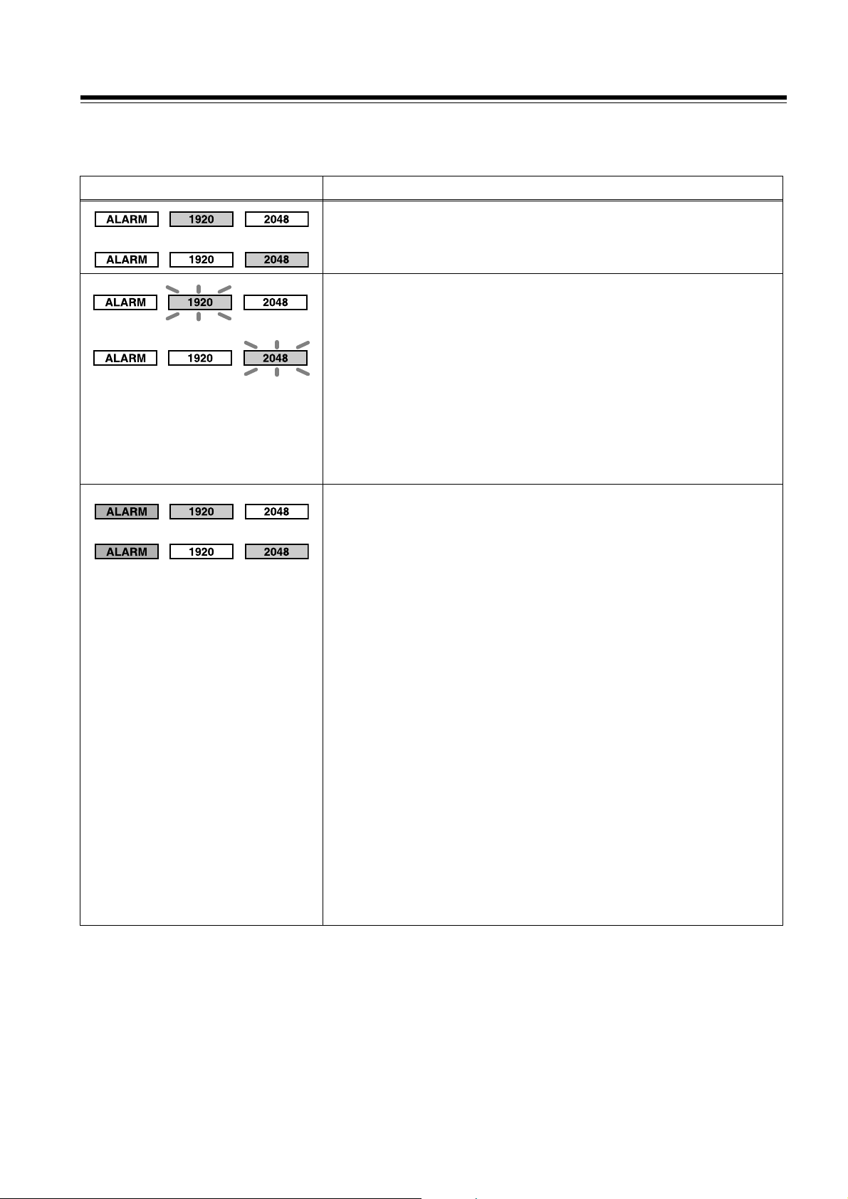
Indicator Display (Front Panel LED)
The operating state of this unit can be checked on the three LEDs (Alarm Lamp, Horizontal Sample
Display Lamps) on the front panel: Lighting or Blinking.
Display Description
Normal operating state
or
or
(Lighting: When there is no warning or when the warnings are masked from
MENU)
Format error
(In the following cases, 1920 LED or 2048 LED blinks normally or rapidly.)
<Warnings indicated by rapid blinking>
RECORDED FORMAT UNMATCH (NO J2K TAPE):
TAPE is not
<Warnings indicated by normal blinking>
RECORDED FORMAT UNMATCH:
There is a mismatch between SYSTEM FORMAT of the unit selected in
settings and FORMAT of TAPE. (2048/1920, XYZ/RGB)
UNMATCH H SAMPLE BETWEEN INPUT SIGNAL AND SYSTEM:
There is a mismatch in H SAMPLE between the SYSTEM set value and the
input signal.
2K processor
recording format.
(Lighiting or Blinking)
or
Other errors
(ALARM Lighting or Blinking: In the case of a warning corresponding to an alarm
indication)
<Warning corresponding to lighting alarm>
2K FAN STOP: The fan of the 2K processor stops.
2K NO REMOTE: The service switch on the back of the 2K processor is not in
the OFF position.
<Warnings corresponding to blinking alarm>
CRC ERROR IN SERIAL DATA INPUT FROM HDD5:
A CRC error occurs in SERIAL DATA (HD SDI) signals from the HD-D5
VTR main unit to the 2K processor.
OUT OF RANGE OF SYSTEM PHASE BETWEEN REF AND INPUT:
There is a large phase difference between the input signal and REF IN.
INPUT SIGNAL UNMATCH SYSTEM FREQUENCY:
There is a mismatch in frame frequency between the SYSTEM set value
and the input signal.
SUBSTANDARD TIMING DIFFERENCE IN DUAL LINK 2K INPUT:
The timing-phase difference of Dual-Link IN A/Bch is big.
CRC ERROR IN DUAL LINK CHA 2K INPUT:
A CRC error occurs in signals on Dual-Link IN Ach.
CRC ERROR IN DUAL LINK CHB 2K INPUT:
A CRC error occurs in signals on Dual-Link IN Bch.
NO EXTERNAL HD_REFERENCE:
HD REF IN on the HD-D5 VTR is not connected.
(Although this is the existing warning for the HD-D5 VTR, the ALARM LED
of the 2K Processor also blinks.)
13
Page 14

Connection Check
After the regular system is connected, it is possible to
check which devices are connected to each other by
executing CONNECTION CHECK in the Front Panel
MENU of the HD-D5 VTR when you own more than
one unit of the 2K Processor and HD-D5 VTR.
Service Switch (Rear)
ON
SERVICE
OFF
All three LEDs of “ALARM”, “2048” and “1920”
repeatedly blink during the operation described on the
left. (For the regular system connection)
<Note>
Service Switch (only Use Service Maintenance)
This slide switch is only for service mode.
Please make sure slide OFF for Normal Operation.
Power On
For the power supply to each unit, construct 2K
SYSTEM and then turn on the power to the 2K
Processor, before turning on the power to the HD-D5
VTR.
14
Page 15

Restrictions
Reference vs. Input Signal Phase
The 2K processor does not have input buffer memory;
therefore, be sure to lock and match the phase between
the reference signal and input signals. If the signal
phases are not locked and matched, the phase of
signals, output signals might be corrupted.
System vs. Input Signal Frequency
The 2K processor does not have input buffer memory;
therefore, be sure to match the frequencies between the
system settings and input signals. If the frequencies are
not matched, output signals might be corrupted.
4:2:2 (Y Pb Pr) Output
The 2K Processor has no built-in gamma conversion.
Therefore, in the output of 4:2:2 (YPbPr color space),
only conversion from RGB (gamma = 2.2) produces
the correct hue. The hue varies in other cases.
Video Output in SEARCH and FF/REW
Video output in SEARCH and FF/REW is with lowresolution images, with low image quality.
SYSTEM setting for RGB and XYZ color
spaces
The input of color space signals that differ from those
in SYSTEM results in incorrect color space output.
Playback of recording color space signals on tapes
that differ from those in SYSTEM results in incorrect
color space output.
SYSTEM settings for 2048 and 1920
horizontal samples
Recording and playback depend on the SYSTEM
settings.
z Recording is based on the number of horizontal
samples in SYSTEM settings and Tape ID, even
when different input signals from those in SYSTEM
are supplied.
z Playback is based on the number of horizontal
samples in SYSTEM settings, even when tape with
a different number of horizontal samples from
those in SYSTEM is played back.
Example 3:
Playback of recording tape for 2048 with 1920
selected in SYSTEM settings:
On each side, 64 samples are cropped for
playback as 1920 samples.
Example 4:
Playback of recording tape for 1920 with 2048
selected in SYSTEM settings:
Black signals of 64 samples are added to each
side for playback as 2048 samples.
In 4:2:2 output, it appears as normal HD signals
with normal output due to the Side Crop function.
Example 5:
Playback of recording tape in the format of 1080/
23PsF 4:2:2 with 1920 selected in SYSTEM settings:
FRONT LED “1920” blinks rapidly. The output
signals are the freeze frame of the last image.
Differences in the actual image conditions due to
differences in the number of H Samples between
SYSTEM settings and input signals (According to the
SYSTEM settings)
SYSTEM
settings
(MENU
selection)
2048
Input signals Recorded images
2048
2048
1920
1920
1920
64 64
2048
1920
2048
1920
In the above case, FRONT LED (2048/1920) blinks
according to SYSTEM settings.
In addition, when a format other than that supporting
the 2K processor is played back, it blinks rapidly
according to the SYSTEM settings.
Example 1:
Input of 2048 signals with 1920 selected in
SYSTEM settings:
On each side, 64 samples are cropped to record
as 1920 samples. (Tape ID = 1920)
Example 2:
Input of 1920 signals with 2048 selected in
SYSTEM settings:
Black signals of 64 samples are added to each
side to record as 2048 samples. (Tape ID = 2048)
1920
2048
2048
1920
1920
1920 1920
64 64
1920
15
Page 16

Restrictions (Continued)
Differences in the actual image conditions due to differences in the number of H Samples between SYSTEM settings
and Tape playback (Tape recording ID) (According to the SYSTEM settings)
SYSTEM settings
(MENU selection)
2048
TAPE playback signals
2048
2048
1920
H CROP
(MENU selection)
CTR CROP
L CROP
R CROP
SAMPLING = 4:4:4
output images
2048
1920
SAMPLING = 4:2:2
output images
1920
1920
1920
1920
1920
1920
2048
2048
1920
1920
1920
CTR CROP
L CROP
R CROP
2048
64 64
1920
64 64
1920
1920
1920
1920
1920
Internal signal source (INT-SG)
z There are four internal signal sources: CB1, CB2,
BLACK, and WHITE. (10-bit precision)
z XYZ and RGB color spaces are expressed
differently, resulting in a difference in the internal
signal format.
<In SYSTEM Color Space = RGB>
CB1: 100% Color Bar
CB2: 75% Color Bar
16
<In SYSTEM Color Space = XYZ>
CB1: Color Bar Signal Pattern 1
CB2: Color Bar Signal Pattern 2
INPUT CHECK Function
Pressing the INPUT CHECK button changes the TC
display in the monitor output SUPER and the TCG
display in the front panel to the internal TCG.
The INPUT CHECK function on the HD-D5 VTR
Front Panel is disabled.
Page 17

Rack Mounting
The unit can be installed in a 19-inch standard rack using the rack-mount adaptors supplied with the unit.
We recommend using the slide rails and brackets specified below for the installation.
CC3001-99-0191 slide rails and B-308 brackets are made by CHASSIS TRAK.
For further details, consult your dealer.
1 Remove the four feet from the unit’s bottom panel.
z Take care to avoid exposing the unit to vibration
or impact.
2 Mount the slide rail inner members onto the unit.
z The length of the mounting screws is limited.
Use the screws (M4a10) provided with the slide
rails.
If one or more mounting screws are lost or
misplaced, use screws less than 10 mm long.
z Be sure to fully tighten the inner members in the four
places on the left and right.
5 Remove the stoppers of the inner members, and
install the unit in the rack.
After installation, check that the unit moves
smoothly.
z Keep the temperature in the rack between 5°C
(41°F) and 40°C (104°F)
z Use the rack-mount angular brackets supplied with
the unit.
3 Attach the outer members of the slide rails and
the brackets to the rack.
◆Note
Check that the height is the same on the left and
the right.
4 Attach the rack-mount adaptors supplied with the
unit to the unit.
z Use the screws provided with the rack-mount
adaptors as the mounting screws.
z Be sure to fully tighten the rack-mount adaptors in
the two places on the left and the right sides.
17
Page 18

Specifications
[GENERAL]
Power supply:
Rated Current:
indicates safety information.
Operating Temperature:
5°C to 40°C (41°F to 104°F)
Operating Humidity:
10% to 80% (no condensation)
Weight:
Approx. 7.5 kg (16.5 lb)
Dimensions (W a H a D):
(not including supporting feet, jacks, connectors
and fan.)
424 mm a 87 mm a 470 mm (2U size)
(16-3/4 inches a 3-7/16 inches a 18-1/2 inches)
Recording Video Signal:
2048 a 1080/23.98p, 24p XYZ/RGB 4:4:4
1920 a 1080/23.98p, 24p XYZ/RGB 4:4:4
Video Recording Format:
HD-D5 JPEG2000
Audio Recording Format:
48 kHz/24 bits, 8CH
Recording Media:
HD-D5 Tape
Recording/Playback Time:
AJ-D5C124LP Approx. 155 min.
Digital Slow:
-1 to +1 times normal speed
Search Speed:
Max. 50 k
Edit Frame Accuracy:
n0 Frame
AC 120 V, 50/ 60 Hz
0.6 A
[VIDEO]
Sampling Frequency:
74.176 MHz/74.25 MHz
Quantizing:
XYZ/RGB 4:4:4, 12 bits
Video Compression Format:
JPEG2000 (ISO/IEC15444)
Error Correction:
Reed-Solomon product code
Video Bit Rate:
Max. 188 Mbps
_Video Input Signal
Dual Link SDI Input:
BNC a 2, 75 Ω
1920 a 1080/23.98PsF, 24PsF 4:4:4
SMPTE 372M/291M/292M/299M standard
2048 a 1080/23.98PsF, 24PsF 4:4:4
_Video Output Signal
Dual Link SDI Output:
(Single HD SDI Output in case of 4:2:2)
BNC a 2 a 2, 75 Ω
1920 a 1080/23.98PsF, 24PsF 4:4:4
SMPTE 372M/291M/292M/299M standard
2048 a 1080/23.98PsF, 24PsF 4:4:4
1920 a 1080/23.98PsF, 24PsF YPbPr 4:2:2
SMPTE 291M/292M/299M standard
Single HD SDI Monitor output:
BNC a 1, 75 Ω (SUPER ON/OFF)
1920 a 1080/23.98PsF, 24PsF YPbPr 4:2:2
SMPTE 292M standard
(Video Signal only w/o ANC data)
[Audio]
Sampling Frequency:
48 kHz (sync video)
Quantizing:
24 bits
18
_Audio Input Signal
Dual Link SDI Input: (Embedded Audio)
BNC a 2, 75 Ω (LinkA only) 8CH
SMPTE 299M standard
_Audio Output Signal
Dual Link SDI Output: (Embedded Audio)
BNC a 2 a 2, 75 Ω (LinkA only) 8CH
SMPTE 299M standard
Page 19

Specifications (Continued)
[TC]
_TC Input Signal
Dual Link SDI Input: (Embedded LTC/VITC)
BNC a 2, 75 Ω (LinkA only)
SMPTE 291M standard
_TC Output Signal
Dual Link SDI Output: (Embedded LTC/VITC)
BNC a 2 a 2, 75 Ω (LinkA only)
SMPTE 291M standard
[Other Input and Output]
HD Reference Input:
BNC a 2 (loop-through a1),
75 Ω automatic termination
HD(1920 a 1080/23.98PsF, 24PsF) tri-level sync
HD SYNC Output:
BNC a 1, 75 Ω
HD(1920 a 1080/23.98PsF, 24PsF) tri-level sync,
Advanced Reference signal for HD-D5 VTRs
Serial Data Output (VTR HD SDI):
BNC a 1, 75 Ω
1920 a 1080/23.98PsF, 24PsF
SMPTE 292M compliance
Serial Data Input (VTR HD SDI):
BNC a 1, 75 Ω
1920 a 1080/23.98PsF, 24PsF
SMPTE 292M compliance
[Accessories (supplied)]
Power cord (1)
Rack-mount adaptor (2)
Weight and dimensions shown are approximate.
Specifications are subject to change without notice.
19
Page 20

Panasonic Broadcast & Television Systems Company
©
Unit Company of Panasonic Corporation of North America
Executive Office:
One Panasonic Way 4E-7, Secaucus, NJ 07094 (201) 348-7000
EASTERN ZONE:
One Panasonic Way 4E-7, Secaucus, NJ 07094 (201) 348-7196
Southeast Region: (201) 348-7162
WESTERN ZONE:
3330 Cahuenga Blvd W., Los Angeles, CA 90068 (323) 436-3500
Government Marketing Department:
One Panasonic Way 2E-10, Secaucus, NJ 07094 (201) 348-7587
Broadcast PARTS INFORMATION & ORDERING:
9:00 a.m. – 5:00 p.m. (EST) (800) 334-4881/24 Hr. Fax (800) 334-4880
Emergency after hour parts orders (800) 334-4881
TECHNICAL SUPPORT:
Emergency 24 Hour Service (800) 222-0741
Panasonic Canada Inc.
5770 Ambler Drive, Mississauga, Ontario L4W 2T3 (905) 624-5010
Panasonic de Mexico S.A. de C.V.
Av angel Urraza Num. 1209 Col. de Valle 03100 Mexico, D.F. (52) 1 951 2127
Panasonic Puerto Rico Inc.
San Gabriel Industrial Park, 65th Infantry Ave., Km. 9.5, Carolina, Puerto Rico 00630 (787) 750-4300
2007 Matsushita Electric Industrial Co., Ltd. All Rights Reserved.
P
 Loading...