

Panasonic AJ-HDP151P Operating Instructions Manual

DVCPRO HD Codec Unit
AJ- P
Operating Instructions
P
O
W
E
R
I
N
P
U
T
E
N
T
E
R
E
S
C
A
P
E
S
H
I
F
T
M
E
N
U
S
E
T
D
I
A
G
O
N
O
F
F

2
CAUTION
RISK OF ELECTRIC SHOCK
DO NOT OPEN
CAUTION: TO REDUCE THE RISK OF ELECTRIC SHOCK,
DO NOT REMOVE COVER (OR BACK).
NO USER SERVICEABLE PARTS INSIDE.
REFER TO SERVICING TO QUALIFIED SERVICE PERSONNEL.
The lightning flash with arrowhead symbol,
within an equilateral triangle, is intended to
alert the user to the presence of uninsulated
“dangerous voltage” within the product’s
enclosure that may be of sufficient magnitude
to constitute a risk of electric shock to
persons.
The exclamation point within an equilateral
triangle is intended to alert the user to the
presence of important operating and
maintenance (service) instructions in the
literature accompanying the appliance.
indicates safety information.
CAUTION:
O
Keep the temperature inside the rack to
between 41°F to 95°F (5°C to 35°C).
O
Bolt the rack securely to the floor so that it
will not topple over when this unit is drawn
out.
IMPORTANT
“Unauthorized recording of copyrighted
television programs, video tapes and other
materials may infringe the right of copyright
owners and be contrary to copyright laws.”
WARNING:
TO REDUCE THE RISK OF FIRE OR SHOCK
HAZARD, DO NOT EXPOSE THIS EQUIPMENT
TO RAIN OR MOISTURE.
CAUTION:
TO REDUCE THE RISK OF FIRE OR SHOCK
HAZARD AND ANNOYING INTERFERENCE,
USE THE RECOMMENDED ACCESSORIES
ONLY.
CAUTION:
TO REDUCE THE RISK OF FIRE OR SHOCK
HAZARD, REFER MOUNTING OF THE
OPTIONAL INTERFACE BOARD TO
QUALIFIED SERVICE PERSONNEL.
FCC Note:
This device complies with Part 15 of the FCC Rules.
To assure continued compliance follow the attached
installation instructions and do not make any
unauthorized modifications.
This equipment has been tested and found to comply
with the limits for a class A digital device, pursuant to
Part 15 of the FCC Rules. These limits are designed to
provide reasonable protection against harmful
interference when the equipment is operated in a
commercial environment. This equipment generates,
uses, and can radiate radio frequency energy and, if
not installed and used in accordance with the
instruction manual, may cause harmful interference to
radio communications. Operation of this equipment in a
residential area is likely to cause harmful interference
in which case the user will be required to correct the
interference at his own expense.
CAUTION:
Do not install or place this unit in a bookcase,
built-in cabinet or any other confined space in
order to maintain adequate ventilation.
Ensure that curtains and any other materials
do not obstruct the ventilation to prevent risk
of electric shock or fire hazard due to
overheating.
$
THIS APPARATUS MUST BE EARTHED
To ensure safe operation the three-pin plug must be
inserted only into a standard three-pin power point
which is effectively earthed through the normal household wiring.
Extension cords used with the equipment must be
three-core and be correctly wired to provide
connection to earth. Wrongly wired extension cords
are a major cause of fatalities.
The fact that the equipment operates satisfactorily
does not imply that the power point is earthed and that
the installation is completely safe. For your safety, if in
any doubt about the effective earthing of the power
point, consult a qualified electrician.

3
Introduction . . . . . . . . . . . . . . . . . . . . . . . . 3
Parts and Their Functions . . . . . . . . . . . . 4
Front panel . . . . . . . . . . . . . . . . . . . . . . . . . . . . . . 4
Rear panel . . . . . . . . . . . . . . . . . . . . . . . . . . . . . . . 5
Examples of Connections . . . . . . . . . . . . 6
Rack Mounting. . . . . . . . . . . . . . . . . . . . . . 7
Status Displays . . . . . . . . . . . . . . . . . . . . . 8
Setup Menus . . . . . . . . . . . . . . . . . . . . . . 10
$ Basic Operation . . . . . . . . . . . . . . . . . . . . . . . . 10
$ Switching between menus . . . . . . . . . . . . . . . . 10
$ Switching between the encoder and decoder . 10
$ Menu initialization . . . . . . . . . . . . . . . . . . . . . . 10
SYSTEM menu . . . . . . . . . . . . . . . . . . . . . . . . . . 11
BASIC menu . . . . . . . . . . . . . . . . . . . . . . . . . . . . 12
TIME CODE menu. . . . . . . . . . . . . . . . . . . . . . . . 13
VIDEO menu . . . . . . . . . . . . . . . . . . . . . . . . . . . . 14
AUDIO menu . . . . . . . . . . . . . . . . . . . . . . . . . . . . 17
Contents
Superimposed Screens . . . . . . . . . . . . . 18
Warning Messages and DIAG Display. . 19
How To Install Optional Circuit Board. . 20
Connectors . . . . . . . . . . . . . . . . . . . . . . . 21
Specifications . . . . . . . . . . . . . . . . . . . . . 22
The AJ-HDP151P is a codec (encoder/decoder) unit
which is used in combination with an HD/SD multiformat DVCPRO server (AJ-HDR150) to record and
play back DVCPRO HD (high definition) format
signals. Switching between the encoder and decoder
is accomplished by means of setup menu operations.
HD signals can be recorded and played back in the
AJ-HDR150 by fitting the optional SDTI circuit board
(AJ-YAC7000P) and connecting with the unit.
This unit can convert the decoded HD signal system
into an SD (standard definition) signal system by
installing the optional HD-SD format converter board
(AJ-UDC150P) in this unit.
Introduction
4
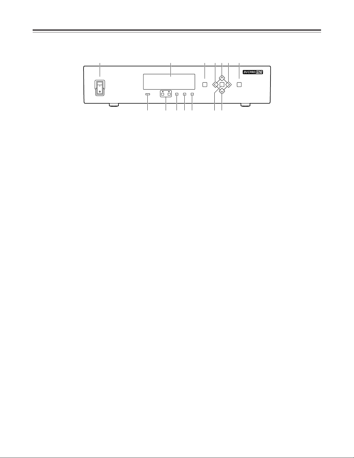
Parts and Their Functions
1 POWER switch
This is used to switch the power ON and OFF.
Do not switch the power back on immediately after
switching it off. After the power has been switched
off, wait at least 5 seconds before switching it back
on.
2 Display panel
Format display:
Indicates the codec format.
Status display:
Indicates the codec status (video/audio input,
time code, etc.).
When either of the scroll buttons 4 is pressed,
the display can be scrolled to the left or right.
Setup menu display:
The setup menu is displayed when the MENU
button 8 is pressed.
3 Input condition lamp
This lights or flashes depending on the condition of
the input signals.
Lit
: The lamp lights when all the necessary
signals are input.
Flashing
: The lamp flashes when the video signals
(HD SDI or SDTI) are input but the other
audio signals and/or reference signal are
not input.
Off
: The lamp is off when the video signals are
not input.
4 Scroll buttons
These enable the display to be scrolled to the left or
right when the status is displayed on the display
panel.
5 ENTER button
This is pressed to enter a setup menu setting after
that setting has been selected.
6 ESCAPE button
This is pressed to ignore or cancel a setup menu
setting after that setting has been selected.
7 SHIFT button
This is pressed together with the [# ] button or [2]
button to change the mode (encoder/decoder, etc.)
during the setup menu setting process.
8 MENU button
This is pressed when a setup menu is to be
operated.
When it is pressed, the setup menu number and
item appear on the display panel.
When a video monitor has been connected to the
HD SDI OUT3 connector or SD SDI OUT3
connector, the setup menu will appear on the
monitor screen.
When the MENU button is pressed again, the setup
menu setting mode is finished and the original
status is restored.
9 SET button
This is pressed to enter a setup menu setting after
that setting has been selected. When the setup
menu data is entered, the setup menu setting mode
is finished and the original status is restored.
: DIAG button
This is used to display the unit ’s information on the
monitor screen when a video monitor has been
connected to the HD SDI OUT3 connector or SD
SDI OUT3 connector.
When the DIAG button is pressed again, the
original status of the screen display is restored.
For further details, refer to “Warning messages and
DIAG display.” (See page 19)
; Left [!] and right [1 ] buttons
These are used to select a setting during the setup
menu item setting process.
< Up [#] and down [2 ] buttons
These are used to select an item during the setup
menu item setting process.
Front panel
POWER
INPUT ENTER ESCAPE SHIFT
MENU
SET
DIAG
ON
OFF
1 2 8 :< ;;
<93 5 6 74
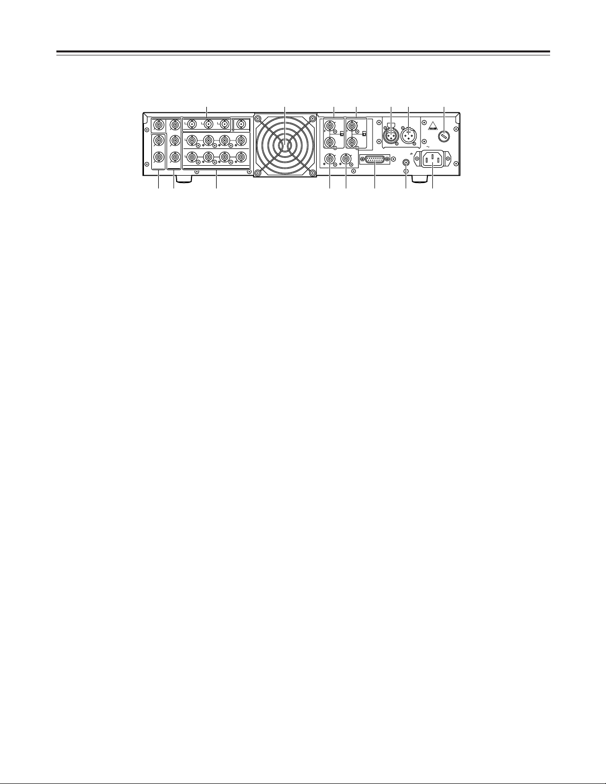
5
9 SD SERIAL DIGITAL COMPONENT AUDIO
VIDEO OUT connectors
When the optional HD-SD format converter board
(AJ-UDC150P) is installed in the unit, digital
component audio and video signals complying with
the SMPTE 259M-C, 272M and 294M standards
are output from these connectors.
Signals with the time code and menu contents
superimposed onto them are output from the SD
SDI OUT3 connector.
: SD REF IN connectors and 75 Ω termination
switch
These are the input connectors for the SD
reference video signals. Input NTSC signals
containing color burst signals.
Set the termination switch to ON for termination.
; HD REF IN connectors and 75 Ω termination
switch
These are the input connectors for the HD
reference video signals. Input tri-level sync signals
with both positive and negative polarities.
Set the termination switch to ON for termination.
< HD REF OUT connector
The HD reference video signal for gen-lock is
output from this connector.
Tri-level sync signals with both positive and
negative polarities are output.
= SD REF OUT connector
Black burst signal for NTSC gen-lock is output from
this connector.
> DIGITAL AUDIO IN/OUT connectors
Digital audio signals complying with the AES/EBU
standards are input to and output from these
connectors.
? ENCODER REMOTE connector
The encoder remote controller is connected here to
enable the video output signal settings to be
adjusted.
1 AC IN socket [~AC IN]
The power cable (provided with the unit) is
connected here.
2 SIGNAL GND terminal
This is the grounding terminal to reduce the noise
level.
It is connected with the signal ground terminal on
the component to which the unit is connected.
This is not a safety ground.
3 Fuse holder
This contains a 125 V 5 A fuse.
4 Cooling fan
This prevents the internal temperature from rising.
5 TIME CODE IN connector
This is the input connector for the external time
code.
6 TIME CODE OUT connector
This is the output connector for the decoded time
code.
7 HD SERIAL DIGITAL COMPONENT AUDIO
VIDEO IN/OUT connectors
These HD digital component audio and video signal
input and output connectors comply with the
SMPTE 292M standard.
Signals with the time code and menu contents
superimposed onto them are output from the HD
SDI OUT3 connector.
8 SDTI IN/OUT connectors
These input and output connectors for compressed
data comply with the SMPTE 305M standard.
Parts and Their Functions
Rear panel
PUSH
IN
OUT1
AUDIO
CH1·2 CH3·4 CH5·6 CH7·8
SD REF
IN
IN
IN
OUT
HD SDTI HD SDI
OUT 3
(SUPER)
OUT 2
OUT
1
OUT 2
SD SDI
DIGITAL AUDIO
OPTION
OUT 3
(SUPER)
AUDIO
CH1·2 CH3·4 CH5·6 CH7·8
OUT
HD REF
ENCODER REMOTE
TC IN
SIGNAL
GND
TC OUT
AC IN
FUSE
125V 5A
T
IN
HD REF
OUT
ON
OFF
75≠
ON
OFF
75≠
SD REF
OUT
35 64
12?<=8 >7
9 : ;
6
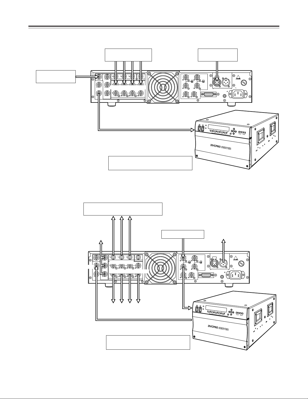
Examples of Connections
When using the unit as an encoder
Digital audio signals
(if required)
HD SDI signal
The SDTI I/O circuit board (AJ-YAC7000P)
is required for the AJ-HDR150.
LTC
(if required)
When using the unit as a decoder
The HD-SD format converter board (AJUDC150P) is required.
SD reference signal
The SDTI I/O circuit board (AJ-YAC7000P)
is required for the AJ-HDR150.
HD SDI IN
OUT1
IN
OUT
IN
OUT 2
OUT 3
OUT
HD SDTI HD SDI
OUT 2
1
AUDIO
CH1·2 CH3·4 CH5·6 CH7·8
IN
DIGITAL AUDIO IN
AUDIO
CH1·2 CH3·4 CH5·6 CH7·8
OUT
(SUPER)
HD SDTI OUT
OUT 3
(SUPER)
SD SDI
DIGITAL AUDIO
OPTION
SD REF
SD REF
AJ-HDP151
SDTI IN
IN
ON
75≠
OFF
HD REF
OUT
OUT
TC IN
HD REF
IN
PUSH
ON
75≠
OFF
TC IN
ENCODER REMOTE
AJ-HDR150
SIGNAL
GND
TC OUT
AC IN
FUSE
T
125V 5A
HD SDI OUT
OUT1
OUT 2
OUT 3
(SUPER)
SD SDI
AUDIO
CH1·2 CH3·4 CH5·6 CH7·8
SD SDI OUT
IN
AUDIO
CH1·2 CH3·4 CH5·6 CH7·8
OUT
DIGITAL AUDIO OUT
(SUPER)
DIGITAL AUDIO
HD SDTI IN
IN
OUT
IN
OUT 2
OUT
OUT 3
HD SDTI HD SDI
1
OPTION
AJ-HDP151
REF IN
SD REF
SD REF
SDTI OUT
HD REF
IN
ON
75≠
OFF
HD REF
OUT
OUT
IN
PUSH
ON
75≠
OFF
TC IN
ENCODER REMOTE
SIGNAL
AJ-HDR150
GND
TC OUT
TC OUTSD REF IN
FUSE
T
125V 5A
AC IN

7
Rack Mounting
The unit can be mounted in a 19-inch standard rack using the accessory rack-mounting adapters.
It is recommended that the slide rails and brackets specified below be used for installation.
CC3001-99-0191 slide rails and B-308 brackets made by CHASIS TRAK.
For further details, consult your dealer.
1. Remove the four feet from the unit’s bottom panel.
O Take care not to subject the unit to vibration or
impact.
3. Mount the slide rail inner members onto the unit.
4. Attach the outer members of the slide rails and the
brackets to the rack.
<Note>
Check that the height is the same at the left and
right.
6. Remove the stoppers of the inner members, and
install the unit in the rack.
After installation, check that the unit moves
smoothly.
O Keep the temperature inside the rack within the
41°F to 95°F (5°C to 35°C) range.
O Bolt the rack securely to the floor to prevent it
from toppling over when the unit is pulled out.
O Use the screws provided with the rack-mounting
adapters as the mounting screws.
O Be absolutely sure to screw down the rack-
mounting adapters in the two places each on the
left and right.
O The length of the mounting screws is subject to
restriction.
Use the screws (M4a10) provided with the slide
rails.
If one or more mounting screws have been lost
or misplaced, use screws less than 10 mm long.
O Be absolutely sure to screw down the inner
members in the four places each on the left and
right.
2. Mount the slide rail spacers onto the unit.
O Use the flat countersunk head screws provided
with the slide rail spacers as the mounting
screws.
O Be absolutely sure to screw down the slide rail
spacers in the two places each on the left and
right.
5. Attach the rack-mounting adapters to the unit.

8
Status Displays
Each status item consists of six characters.
The item designation appears on the first line and its status on the second line.
Three items can be indicated simultaneously on the unit’s display panel.
Using the scroll buttons, the displays can be scrolled to the left or right to display other items.
Example of display:
VVIIDD__IINN EENNCCFFMMTT EENNCCFFLLDD
HHDD__SSDDII 11008800ii 5599..9944
Display
sequence
Status
display
item
Status displayed
2 ENCFMT Displays the format of the video
signals to be encoded.
1080i: 1080i format signals are
encoded.
720P: 720P format signals are
encoded.
3 ENCFLD Displays the field frequency of the
signals to be encoded.
59.94: The signals are encoded with a
field frequency of 59.94 Hz.
4 TC Indicates whether the time code is in
the drop frame or non-drop frame
mode.
DF: Drop frame mode.
NDF: Non-drop frame mode.
5 TC_IN Displays the status of the time code
input signal.
LTC: The LTC signal of the TIME
CODE IN connector is used as
the time code input.
SLTC: The LTC information added to
the HD SDI signal is used as
the time code input.
SVITC: The VITC information added
to the HD SDI signal is used
as the time code input.
<Note>
Each display flashes if the
corresponding time code signal is not
input.
6
7
8
9
A12_IN
A34_IN
A56_IN
A78_IN
Displays the status of the audio input
signals.
AES:The AES audio signals of the
DIGITAL AUDIO IN connectors
are used as the audio input
signals.
The display flashes if the AES
audio signals are not input.
SDI: The HD SDI embedded audio
signals are used as the audio
input signals.
The display flashes if the HD
SDI signal is not input or if the
audio signal is not embedded
even when it is input.
INT_SG:
The signals of the internal signal
generator are used as the audio
input signals.
List of status display items
When the unit is used as an encoder
Display
sequence
Status
display
item
Status displayed
1 VID_IN Displays the video input signal status.
HD_SDI: Indicates that HD SDI video
signals are input; flashes
when no signals have been
input.
INT_CB: Indicates that the video input
signal is the color bars
signal of the internal signal
generator.
INT_MB: Indicates that the video
input signal is the multi burst
signal of the internal signal
generator.
INTRMP: Indicates that the video
input signal is the ramp
signal of the internal signal
generator.
INTBLK: Indicates that the video input
signal is the black signal of
the internal signal generator.
 Loading...