

Page 1
AJ- P
Camera/VTR
Operating Instructions
Page 2
2
indicates safety information.
CAUTION
RISK OF ELECTRIC SHOCK
DO NOT OPEN
CAUTION: TO REDUCE THE RISK OF ELECTRIC SHOCK,
DO NOT REMOVE COVER (OR BACK).
NO USER SERVICEABLE PARTS INSIDE.
REFER TO SERVICING TO QUALIFIED SERVICE PERSONNEL.
The lightning flash with arrowhead symbol,
within an equilateral triangle, is intended to
alert the user to the presence of uninsulated
“dangerous voltage” within the product’s
enclosure that may be of sufficient magnitude
to constitute a risk of electric shock to
persons.
The exclamation point within an equilateral
triangle is intended to alert the user to the
presence of important operating and
maintenance (service) instructions in the
literature accompanying the appliance.
WARNING:
TO REDUCE THE RISK OF FIRE OR SHOCK
HAZARD, DO NOT EXPOSE THIS
EQUIPMENT TO RAIN OR MOISTURE.
CAUTION:
TO REDUCE THE RISK OF FIRE OR SHOCK
HAZARD AND ANNOYING INTERFERENCE,
USE THE RECOMMENDED ACCESSORIES
ONLY.
CAUTION:
TO REDUCE THE RISK OF FIRE OR SHOCK
HAZARD, REFER CHANGE OF SWITCH
SETTING INSIDE THE UNIT TO QUALIFIED
SERVICE PERSONNEL.
FCC Note:
This device complies with Part 15 of the FCC Rules.
To assure continued compliance follow the attached
installation instructions and do not make any
unauthorized modifications.
This equipment has been tested and found to comply
with the limits for a class A digital device, pursuant to
Part 15 of the FCC Rules. These limits are designed
to provide reasonable protection against harmful
interference when the equipment is operated in a
commercial environment. This equipment generates,
uses, and can radiate radio frequency energy and, if
not installed and used in accordance with the
instruction manual, may cause harmful interference to
radio communications. Operation of this equipment in
a residential area is likely to cause harmful
interference in which case the user will be required to
correct the interference at his own expense.
Replace battery with part No. CR2032 only.
Use of another battery may present a risk of fire or
explosion.
Caution—Battery may explode if mistreated.
Do not recharge, disassemble or dispose of in fire.
ATTENTION:
The product you have purchased is powered by a
nickel cadmium battery which is recyclable. At the
end of it’s useful life, under various state and local
laws, it is illegal to dispose of this battery into your
municipal waste stream.
Please call 1-800-8-BATTERY for information on how
to recycle this battery.
Ni-Cd
RBRC
RBRC
Page 3

3
Contents
Introduction . . . . . . . . . . . . . . . . . . . . . . . . . . . . . . .5
Features . . . . . . . . . . . . . . . . . . . . . . . . . . . . . . . . . .5
Features of the camera unit . . . . . . . . . . . . . . . . . .5
Features of the VTR unit . . . . . . . . . . . . . . . . . . . .7
System configuration . . . . . . . . . . . . . . . . . . . . . . .8
Parts and their functions . . . . . . . . . . . . . . . . . . . .9
Power supply section . . . . . . . . . . . . . . . . . . . . . . .9
Accessory mounting section . . . . . . . . . . . . . . . .10
Audio function section . . . . . . . . . . . . . . . . . . . . .11
Viewfinder section . . . . . . . . . . . . . . . . . . . . . . . .13
Shooting (recording)/playback function section . .14
Warning/status display section . . . . . . . . . . . . . . .19
Menu operation section . . . . . . . . . . . . . . . . . . . .20
Time code related section . . . . . . . . . . . . . . . . . .20
Power supply . . . . . . . . . . . . . . . . . . . . . . . . . . . . .22
Using the Anton/Bauer battery pack . . . . . . . . . .22
Using the BP-90 type battery pack . . . . . . . . . . . .23
Using the Sony NP-1/BP-90 battery pack . . . . . .24
Using the V-mount type battery pack . . . . . . . . . .24
Using an AC power supply
when the AJ-B75 AC adapter is used . . . . . . . . .25
Attaching the lens . . . . . . . . . . . . . . . . . . . . . . . . .26
Adjusting the lens flange . . . . . . . . . . . . . . . . . . .27
Adjusting the white shading . . . . . . . . . . . . . . . . .28
Adjusting the viewfinder . . . . . . . . . . . . . . . . . . . .30
Attaching the viewfinder . . . . . . . . . . . . . . . . . . . .30
Detaching the viewfinder . . . . . . . . . . . . . . . . . . .30
Adjusting the viewfinder position . . . . . . . . . . . . .31
Audio input preparation . . . . . . . . . . . . . . . . . . . .32
When attaching a microphone to the viewfinder
(optional accessory) for use . . . . . . . . . . . . . . . . .32
When attaching a microphone to the main unit for
use . . . . . . . . . . . . . . . . . . . . . . . . . . . . . . . . . . . .33
When connecting a microphone to the
MIC IN jack . . . . . . . . . . . . . . . . . . . . . . . . . . . . . .34
When connecting a microphone to the
AUDIO IN connector . . . . . . . . . . . . . . . . . . . . . .34
When using a wireless microphone . . . . . . . . . . .35
When connecting audio components . . . . . . . . . .35
Mounting the unit on a tripod . . . . . . . . . . . . . . . .36
Attaching the shoulder strap . . . . . . . . . . . . . . . .37
Adjusting the shoulder pad position . . . . . . . . . .37
Attaching the rain cover . . . . . . . . . . . . . . . . . . . .38
Connecting the extension control unit . . . . . . . .38
Viewfinder lamp displays . . . . . . . . . . . . . . . . . . .39
Setting the lamp displays . . . . . . . . . . . . . . . .40
Viewfinder screen status displays . . . . . . . . . . . .41
Selecting the display items . . . . . . . . . . . . . . . . . .43
Display modes and setting change messages . . .45
Switching the display mode . . . . . . . . . . . . . . . . .46
Setting the marker displays . . . . . . . . . . . . . . . . .46
Setting the camera ID . . . . . . . . . . . . . . . . . . . . .47
Screen displays . . . . . . . . . . . . . . . . . . . . . . . . . . .48
Remaining battery charge and audio channel level
and remaining tape displays . . . . . . . . . . . . . . . .48
Displays relating to errors and warnings . . . . . . .48
Displays relating to time codes . . . . . . . . . . . . . .48
Adjusting the date and time . . . . . . . . . . . . . . . . .49
Adjustments and setup using the setting
menus . . . . . . . . . . . . . . . . . . . . . . . . . . . . . . . . .49
Adjusting the white balance and black
balance . . . . . . . . . . . . . . . . . . . . . . . . . . . . . . . . . .50
Adjusting the white balance . . . . . . . . . . . . . . . . .50
Adjusting the black balance . . . . . . . . . . . . . . . . .54
Setting the electronic shutter . . . . . . . . . . . . . . . .55
Shutter modes . . . . . . . . . . . . . . . . . . . . . . . . . . .55
Registering the shutter speed . . . . . . . . . . . . . . .55
Setting the shutter mode and speed . . . . . . . . . .56
Changing the shutter speed and mode selection
range . . . . . . . . . . . . . . . . . . . . . . . . . . . . . . . . . .56
Setting the synchro scan mode . . . . . . . . . . . . . .57
Switching the shutter speed display . . . . . . . . . . .57
Film tone gamma function . . . . . . . . . . . . . . . . . .58
Switching the frame frequency . . . . . . . . . . . . . .58
Variable frame rate . . . . . . . . . . . . . . . . . . . . . . . .59
Setting the frame rate . . . . . . . . . . . . . . . . . . . . . .59
Scan reverse . . . . . . . . . . . . . . . . . . . . . . . . . . . . .61
Setting the scan reverse . . . . . . . . . . . . . . . . . . .61
Adjusting the audio level . . . . . . . . . . . . . . . . . . .61
Manual audio level adjustments . . . . . . . . . . . . . .61
Limiter . . . . . . . . . . . . . . . . . . . . . . . . . . . . . . . . .61
Setting the time data . . . . . . . . . . . . . . . . . . . . . . .62
Setting the user’s bit . . . . . . . . . . . . . . . . . . . . . . .62
Setting the time code . . . . . . . . . . . . . . . . . . . . . .63
Externally locking the time code . . . . . . . . . . . . . .64
Tape management information . . . . . . . . . . . . . .65
How to use the user data . . . . . . . . . . . . . . . . . . .66
How to use the scene file . . . . . . . . . . . . . . . . . . .67
Setup card operations . . . . . . . . . . . . . . . . . . . . . .72
Formatting the setup card . . . . . . . . . . . . . . . . . .73
Saving the data settings on the card . . . . . . . . . .74
Loading the data saved on the card . . . . . . . . . . .76
Cassette tapes . . . . . . . . . . . . . . . . . . . . . . . . . . . .78
Recording . . . . . . . . . . . . . . . . . . . . . . . . . . . . . . . .79
Shooting . . . . . . . . . . . . . . . . . . . . . . . . . . . . . . . .80
Scene-to-scene continuity . . . . . . . . . . . . . . . . . .81
Playback
(checking what has been recorded) . . . . . . . . . . .82
Rec review . . . . . . . . . . . . . . . . . . . . . . . . . . . . . .82
Color playback . . . . . . . . . . . . . . . . . . . . . . . . . . .82
Lens RET button functions . . . . . . . . . . . . . . . . . .82
Other VTR functions . . . . . . . . . . . . . . . . . . . . . . .83
NEWS REC function . . . . . . . . . . . . . . . . . . . . . .83
RETAKE function . . . . . . . . . . . . . . . . . . . . . . . . .83
INTERVAL REC (intermittent recording)
function . . . . . . . . . . . . . . . . . . . . . . . . . . . . . . . . .83
Page 4

4
Contents
Menu operations . . . . . . . . . . . . . . . . . . . . . . . . . .84
Basic setting menu operations . . . . . . . . . . . . . . .85
Displaying sub-menus and deciding on
settings . . . . . . . . . . . . . . . . . . . . . . . . . . . . . . . . .86
Setting menu configuration . . . . . . . . . . . . . . . . .87
Setting menu screens . . . . . . . . . . . . . . . . . . . . . .91
<FILM (CAM) MENUS>
FILM (CAM) MAIN MENU 1 screen . . . . . . . . . . .91
FILM (CAM) MAIN MENU 2 screen . . . . . . . . . . .91
FILM (CAM) MAIN MENU 3 screen . . . . . . . . . . .91
FILM (CAM) MAIN MENU 4 screen . . . . . . . . . . .91
FILM (CAM) MAIN MENU 1
ROP screen . . . . . . . . . . . . . . . . . . . . . . . . . . . . .92
MATRIX screen . . . . . . . . . . . . . . . . . . . . . . . . . .92
COLOR CORRECTION 1 screen . . . . . . . . . . . .93
COLOR CORRECTION 2 screen . . . . . . . . . . . .93
LOW SETTING screen . . . . . . . . . . . . . . . . . . . . .94
MID SETTING screen . . . . . . . . . . . . . . . . . . . . .94
HIGH SETTING screen . . . . . . . . . . . . . . . . . . . .95
ADDITIONAL DTL1 screen . . . . . . . . . . . . . . . . .95
ADDITIONAL DTL2 screen . . . . . . . . . . . . . . . . .95
SKIN TONE DTL screen . . . . . . . . . . . . . . . . . . .96
KNEE/LEVEL screen . . . . . . . . . . . . . . . . . . . . . .96
GAMMA screen . . . . . . . . . . . . . . . . . . . . . . . . . .97
CAMERA SETTING screen . . . . . . . . . . . . . . . . .97
FILM (CAM) MAIN MENU 2
VF DISPLAY screen . . . . . . . . . . . . . . . . . . . . . . .98
VF MARKER screen . . . . . . . . . . . . . . . . . . . . . .99
VF INDICATOR screen . . . . . . . . . . . . . . . . . . . .99
CAMERA ID screen . . . . . . . . . . . . . . . . . . . . . .100
SHUTTER SPEED screen . . . . . . . . . . . . . . . . .100
SHUTTER SELECT screen . . . . . . . . . . . . . . . .101
!LED screen . . . . . . . . . . . . . . . . . . . . . . . . . . . .102
CAMERA SW MODE screen . . . . . . . . . . . . . . .102
SUPER GAIN screen . . . . . . . . . . . . . . . . . . . . .104
FRAME MODE screen . . . . . . . . . . . . . . . . . . . .104
FILM (CAM) MAIN MENU 3
CAM CARD READ/WRITE screen . . . . . . . . . . .105
CAM CARD R/W SELECT screen . . . . . . . . . . .105
GENLOCK/IRIS screen . . . . . . . . . . . . . . . . . . .106
LENS ADJ screen . . . . . . . . . . . . . . . . . . . . . . .106
FILM (CAM) MAIN MENU 4
FILM (CAM) USER MENU SELECT 1 screen . .107
FILM (CAM) USER MENU SELECT 2 screen . .107
FILM (CAM) USER MENU SELECT 3 screen . .107
BLACK SHADING screen . . . . . . . . . . . . . . . . .108
WHITE SHADING screen . . . . . . . . . . . . . . . . .108
FLARE screen . . . . . . . . . . . . . . . . . . . . . . . . . .108
COLORIMETRY screen . . . . . . . . . . . . . . . . . . .108
INITIALIZE screen . . . . . . . . . . . . . . . . . . . . . . .108
DIAGNOSTIC screen . . . . . . . . . . . . . . . . . . . . .109
EVALUATION screen . . . . . . . . . . . . . . . . . . . . .109
OPTION screen . . . . . . . . . . . . . . . . . . . . . . . . .109
<VTR MENUS>
VTR MAIN MENU screen . . . . . . . . . . . . . . . . . .111
FUNCTION screen . . . . . . . . . . . . . . . . . . . . . . .112
BATTERY/TAPE screen . . . . . . . . . . . . . . . . . .113
BATTERY SETTING screen . . . . . . . . . . . . . . .114
VTR VF INDICATOR screen . . . . . . . . . . . . . . .115
MIC/AUDIO screen . . . . . . . . . . . . . . . . . . . . . .115
TC/UB screen . . . . . . . . . . . . . . . . . . . . . . . . . . .117
TIME DATE screen . . . . . . . . . . . . . . . . . . . . . .119
VTR USER MENU SELECT screen . . . . . . . . . .119
VTR CARD READ/WRITE screen . . . . . . . . . . .119
VTR INITIALIZE screen . . . . . . . . . . . . . . . . . . .119
DIAGNOSTIC screen . . . . . . . . . . . . . . . . . . . . .119
<VTR USER MENU SELECT>
FUNCTION screen . . . . . . . . . . . . . . . . . . . . . . .120
BATTERY/TAPE screen . . . . . . . . . . . . . . . . . .120
VTR VF INDICATOR screen . . . . . . . . . . . . . . .121
MIC/AUDIO screen . . . . . . . . . . . . . . . . . . . . . .121
TC/UB screen . . . . . . . . . . . . . . . . . . . . . . . . . . .121
Warning system . . . . . . . . . . . . . . . . . . . . . . . . . .122
Emergency eject . . . . . . . . . . . . . . . . . . . . . . . . .124
Error codes . . . . . . . . . . . . . . . . . . . . . . . . . . . . . .124
Maintenance . . . . . . . . . . . . . . . . . . . . . . . . . . . . .125
Condensation . . . . . . . . . . . . . . . . . . . . . . . . . . .125
Head cleaning . . . . . . . . . . . . . . . . . . . . . . . . . .125
Cleaning inside the viewfinder . . . . . . . . . . . . . .125
Phenomena inherent to CCD cameras . . . . . . .125
Replacing the backup battery . . . . . . . . . . . . . . .125
Inspections prior to shooting . . . . . . . . . . . . . . .126
Preparation for inspection . . . . . . . . . . . . . . . . .126
Inspecting the camera unit . . . . . . . . . . . . . . . . .126
Inspecting the viewfinder . . . . . . . . . . . . . . . . . .127
Inspecting the aperture and zoom functions . . .128
Inspecting the VTR unit . . . . . . . . . . . . . . . . . . .128
Specifications . . . . . . . . . . . . . . . . . . . . . . . . . . .130
Page 5

5
Introduction
Features
The AJ-HDC27F is a camera/VTR that supports the
SMPTE-296M 1280a720 scanning standard.
Integrated in this single unit are an HD color video
camera featuring a 1-million pixel IT-CCD unit with onchip lens as the pickup device, and a DVCPRO HD
format VTR incorporating the latest compression
technology.
The camera unit supports a variable frame function
and film tone gamma function, and it also supports the
Ultra Prime lenses for 35 mm film cameras as a
standard feature.
Featuring a 100 Mbps recording rate for the VTR as
well, this unit is capable of recording images with an
extremely high picture quality to achieve the highest
performance and most sophisticated functions as an
integrated camera/VTR for electronic field production
(EFP) applications.
Furthermore, it is compact and lightweight, has low
power consumption, and excels in achieving a high
level of picture quality, sensitivity, and mobility, and is
extremely dust-proof and moisture-proof. These are
all attributes which enable the unit to be used for
electronic news gathering (ENG) applications as well.
Since digital signal processing is provided in both the
camera unit and VTR unit, the picture quality is further
improved while the unit’s stability is also enhanced.
Small multimedia cards or SD memory cards meeting
global standards can be used for the camera and VTR
setting data as part of a system which can accomplish
data management.
Features of the camera unit
The camera unit of the AJ-HDC27F has the
following features.
OHigh sensitivity: 2000 lux, F12
OFrame rate: 4 fps (frame/sec.) to 60 fps
OHigh signal-to-noise ratio: 54 dB (standard)
OLow smear
OLow flare
OScan reverse
OSwitchable frame frequency: 59.94 Hz or 60.00 Hz
Variable frame rate
Frame-drop (under-cranking) shooting and high-speed
(over-cranking) shooting, which are special film
shooting techniques, have been achieved for the first
time in a video camera.
The variable frame rate function can be set as desired
from 4 fps (frame/sec.) to 60 fps.
The shutter speed can also be set from 0.8% of the
frame rate (aperture angle: 3 degrees) to 97.2%
(aperture angle: 350 degrees), enabling full use to be
made of many different presentation techniques.
Along with continually recording at 60 fps, the VTR
unit enables specific effective frames alone to be
marked with time codes so that off-line editing using a
conventional DVCPRO HD VTR is possible. This
makes it possible to construct a 24 fps production
system with minimal equipment investment.
Film tone gamma function
In the beginning, the first and foremost aspect defining
the manifold powers of expression that only the
medium of film could achieve was the extent of a
film’s latitude (reproduction range). What Panasonic
did was to use its resources to develop an exclusive
gamma curve for reproducing film tones by means of
the CCDs, and this led to the capability of expressing
natural gradations and reproducing a rich variety of
colors—something that was beyond the means of
conventional video cameras. The AJ-HDC27F
incorporates a total of three gamma curves—two cine
curves (for films/for videos) and the conventional
video gamma curve—and it enables the curve that
best suits the application at hand to be selected. The
powers of expression achieved as a result are
comparable to those provided by film. The high
sensitivity that is simply superior to film cameras
delivers an excellent balance between brightness and
high picture quality: indeed, the kind of sensitivity that
corresponds to ISO640 enables shooting with the
same kind of feel as ultra-fine-grain films.
When the conventional video gamma curve is to be
used, set the unit to the video mode using the CAM
MENU SEL item on the OPTION screen of FILM
(CAM) MAIN MENU 4.
When one of the cine curves is to be used, set the unit
to the film mode using the CAM MENU SEL item on
the OPTION screen of FILM (CAM) MAIN MENU 4,
and then select the desired curve by setting the CINE
GAMMA SEL item on the GAMMA screen of FILM
MAIN MENU 1.
Page 6

6
Features
Features of the camera unit
Prime lens mode
Not only the lens that does justice to the sensitivity
equivalent to a film but also the various devices and
equipment that are peripheral to the camera combine to
play roles which are so critical that they cannot be
divorced from the technical skills of the person operating
the camera. Using an HD lens adapter made by
Angenieux, this unit supports the ultra-prime lenses used
for film cameras as a standard feature. What’s more,
Panasonic has achieved an industry first by incorporating
as a standard feature, a scan reverse function, which
cancels out image reversal occurring when the adapter is
used, and switching can be easily accomplished by a
menu setting.
The unit also supports slide bases, matte boxes and
other film camera equipment which users may have been
using for years.
A full range of long viewfinders, small LCD monitors and
other options available from related manufacturers is
available, and the maximum can be derived from formats
ranging from films to HD with the same ease afforded by
simply changing the main camera unit.
Film user menu
Panasonic does its best to cater to film camera users not
only on the functions and performance front but also in
terms of operation.
For instance, it has provided a cinema image menu
(FILM USER MENU) which brings together on one page
the setting items that are frequently used in location
cinema shooting.
Along with the gamma curve selection and scan reverse
ON/OFF functions, the settings for the hard and soft
texture adjustments, gradation settings for the shadow
areas, latitude adjustments, and tungsten lighting
(3200K) type or daylight (5600K) type can be selected
just like with films on one menu screen.
Digital signal processing
Analog signals are converted into digital signals through
10-bit A/D conversion at a sampling frequency of
74.1758 MHz (59.94 Hz)/74.25 MHz (60.0Hz).
This processing not only enhances the picture quality,
stability and reliability but it also enables the viewfinder
screen displays and many of the adjustment and setup
items to be configured in a menu-driven format.
4-piece filter disc sets available as standard
accessories
The filter best suited to the subject’s brightness and color
temperature can be selected. Two independent sets of
filter discs, one for CC and one for ND, each with four
filter discs, are provided as standard accessories.
Camera unit equipped to capture a wide range of
image creation activities from cinema production
to broadcasting applications
OA sensitivity of F12 (2000 lux) achieved by the three
highly sensitive CCDs.
The minimum subject brightness is 0.7 lux.
OGamma curves (switchable) for reproducing film
tones.
ONot only a natural choice like 24 fps (frame/sec.) for
films but also any number of shooting frames from
4 fps to 60 fps can be set.
ODigital setup for controlling image production using
numerical values and for simple operation using the
jog dial and gradation menu.
OCinema image menu provided for film producers.
OSetup data in up to 8 files can be stored on an SD
card (optional accessory: RP-SD008B).
OBuilt-in high picture quality circuits including auto
knee, many different detail functions, shading
compensation, 12-axis color compensation circuit
and masking circuit.
OBuilt-in 2-level zebra pattern and spot zebra
functions.
O3 values among the 10 possible settings from –6 dB
(–3 dB in film mode) to +30 dB allocated to the gain
selector; also, the gain can be increased up to +36
dB by the super gain function.
OThe following functions can be allocated to the
USER1 and USER2 buttons: super iris, super gain,
super black, black stretch, audio CH1/CH2 input
front/rear switching, recording start/stop, return
switch, and Y GET (output luminance level
measurement).
OAn electronic shutter with a variable function
over and above the 6 shutter speeds.
OTungsten lighting (3200K) type or daylight (5600K)
type can be selected just like with films on one
menu screen. Two sets of ND&CC optical filters
are featured as a standard option.
OABB (automatic black balance) and AWB
(automatic white balance) functions incorporated.
Two values for each of the four CC filters can be
retained as the AWB values.
OStatuses and warnings are displayed on the
viewfinder screen.
1/100 , 1/120, 1/250, 1/500, 1/1000 and 1/2000 sec.
(or 180.0, 172.8, 144.0, 120.5, 90.0 and 45.0 deg)
0.8% to 97.2% of the frame rate (aperture angle of 3.0 to
350.0 degrees)
Page 7

7
Features of the VTR unit
Digital system
The pictures are compressed by a component digital
recording system that uses the latest compression
technology while non-compression PCM recording
featuring excellent signal-to-noise ratio, frequency
band, waveform characteristics and reproduction of
detailed areas is employed for the sound. The result
is an even higher picture and sound quality.
Power saving management (SAVE REC) function
When this unit is used for recording, its playback
system circuitry is shut down. The output of signals to
the HD SDI OUT connector is also shut down when
the cable has not been connected so that the unit’s
power can be conserved while the unit is being
operated.
Scene-to-scene continuity
Simply by pressing the VTR START button or lens
VTR button, continuity between the scenes is
obtained at a precision of 0 to +1 frame.
Rec review function
The last 2 to 10 seconds of a recording are
automatically rewound and played back to enable the
user to quickly check what has been recorded.
Playback function
This function enables the playback picture (in black
and white) to be viewed on the viewfinder screen.
Color playback pictures can be output from the HD
SDI OUT connector.
Built-in time code generator/reader
The same or separate time code information can be
recorded on the dedicated sub-code track and video
AUX area, and played back.
External locking of time code
The built-in time code generator can be locked to an
external generator. A lithium battery is used as the
backup power supply of the built-in time code
generator to back up the memory data for about a
year even when no power is supplied to the unit.
Tape management information
As the tape management information, this unit
automatically saves the frame rate information on the
shooting speeds, the active frame information on the
first frame where the frame image was switched, and
the active frame count information in the user’s bit of
the sub-code track area (which used to be the LTC
area).
Built-in DOLBY NR system
The cue audio recording circuitry contains a Dolby B
noise reduction circuit.
Audio functions
OA phantom power supply type of microphone
(optional accessory) with sharp directivity
characteristics can be attached. It can also be
detached from the unit for use as an interview
microphone.
OOther kinds of microphones can also be connected
and, using the model AJ-MH700P microphone
holder (optional accessory), attached to the unit.
NEWS REC function
This function especially supports shooting in the
context of news gathering or documentary filming to
ensure that no opportune shutter opportunities are
passed up.
In other words, by controlling the start key
acknowledgment time, the unit can continuously
record without the user having to interrupt the
recording: this safeguards against the failure to record
those precious moments—a failure that occurs when
recording is resumed after it has been shut down
temporarily.
RETAKE function
This function is for not leaving behind superfluous cuts
when a cut turns out to be no good during the
shooting of news, reports or art programs.
Users should remember to handle this function very
carefully.
If there is enough leeway in the shooting time and a
particular cut is clearly judged to be no good, the tape
is rewound to the start of the cut concerned and the
rec pause (rec standby) mode is established by
operating the MODE CHECK button and lens RET
button. Since recording is now commenced from that
point on the tape, the no-good cut will be deleted. In
order to prevent the cut prior to the no-good cut from
being deleted, a part of the no-good cut equivalent to
ten or so frames is left behind.
By cutting down on the time taken for copying onto the
work tape, for instance, this function is very effective
in achieving economical operation.
INTERVAL REC function
This function makes simple interval shooting possible.
It proves to be very effective when shooting programs
with a nature theme or art programs.
Features
O
Dolby noise reduction manufactured under license from Dolby Laboratories Licensing Corporation.
O
“DOLBY” and the double-D symbol Îare trademarks of Dolby Laboratories Licensing Corporation.
Page 8
8
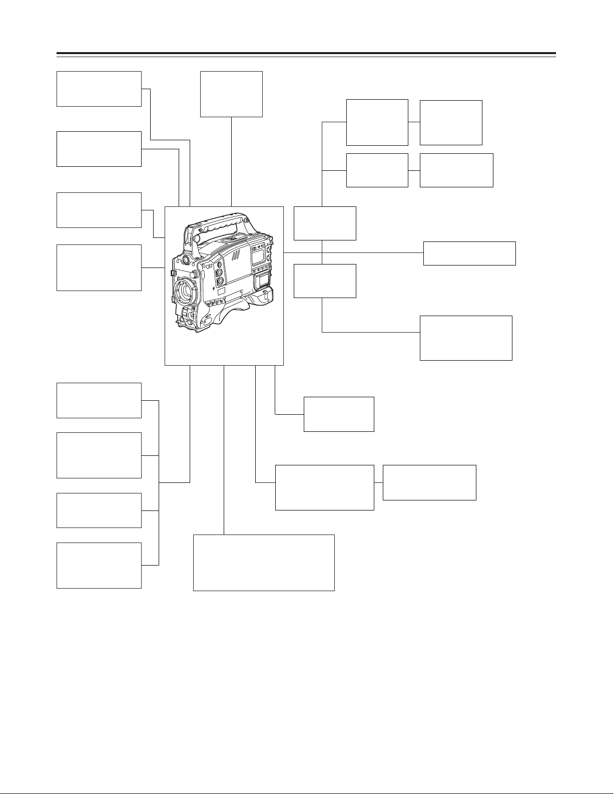
System configuration
Microphone kit
AJ-MC700P
Wireless
microphone
receiver
WX-RJ700
Microphone holder
AJ-MH700P
Lens
(Bayonet type)
FUJINON/CANON
Rain cover
SHAN-RC700
Soft carrying case
AJ-SC900
Tripod mount
adapter
SHAN-TM700
Extension control
unit
AJ-EC3
Camera/VTR
AJ-HDC27F
Setup memory card
Multi-media card:
VW-MMC8
SD (Secure Digital) memory card:
RP-SD008B
Battery case
AU-M402H
AC adapter
AJ-B75
Cassette tape
AJ-HP23LP
AJ-HP32LP
AJ-HP46LP
Cleaning tape
AJ-CL12LP
BP-90 type
battery
Sony
Battery case
NP/BP
adapter plate
V-mount
adapter plate
Sony Battery
BP-90
NP-1
Anton/Bauer Battery
IDX Battery
E-50, E-80
Sony Battery
BP-L60/L90
2.0-inch viewfinder
AJ-HVF27P
Page 9
9
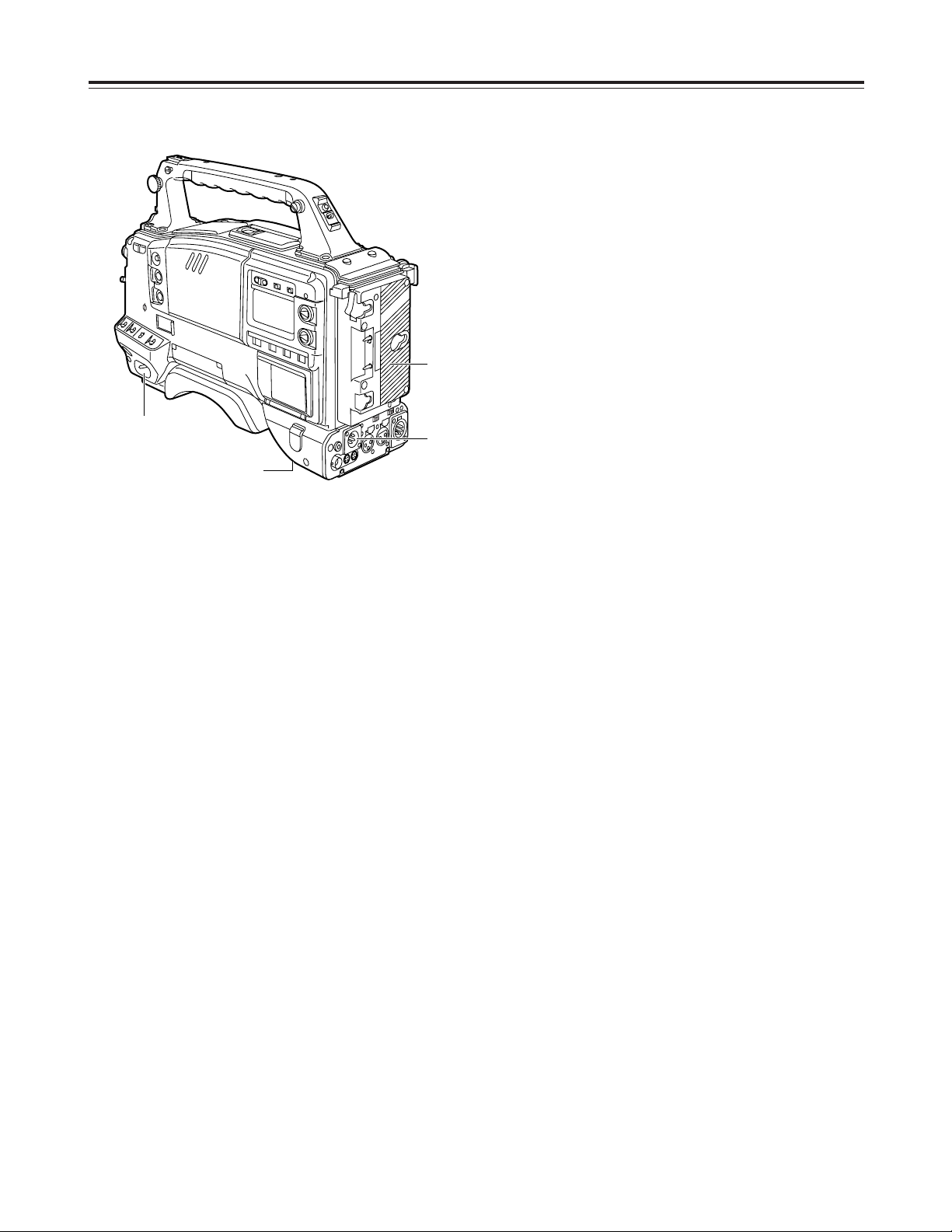
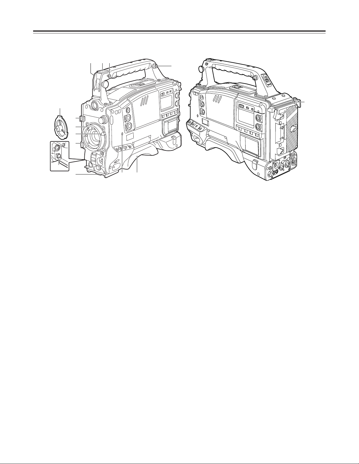
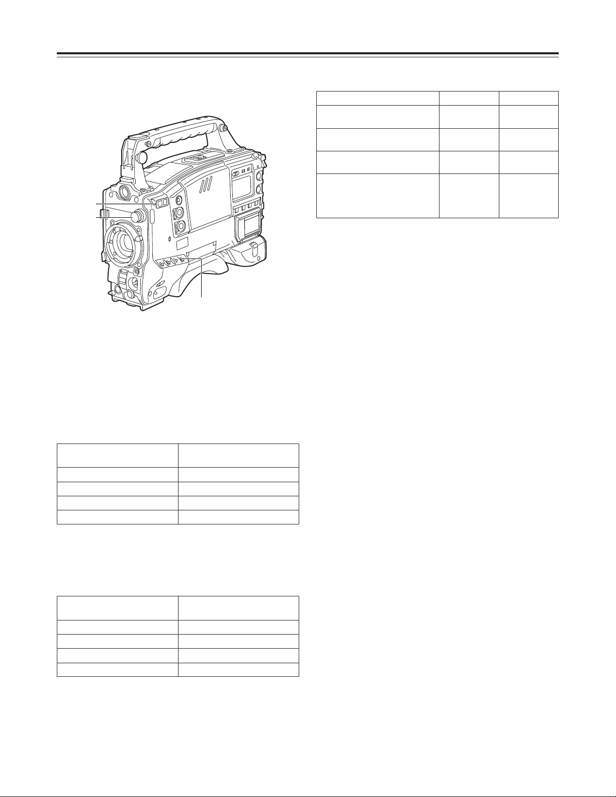
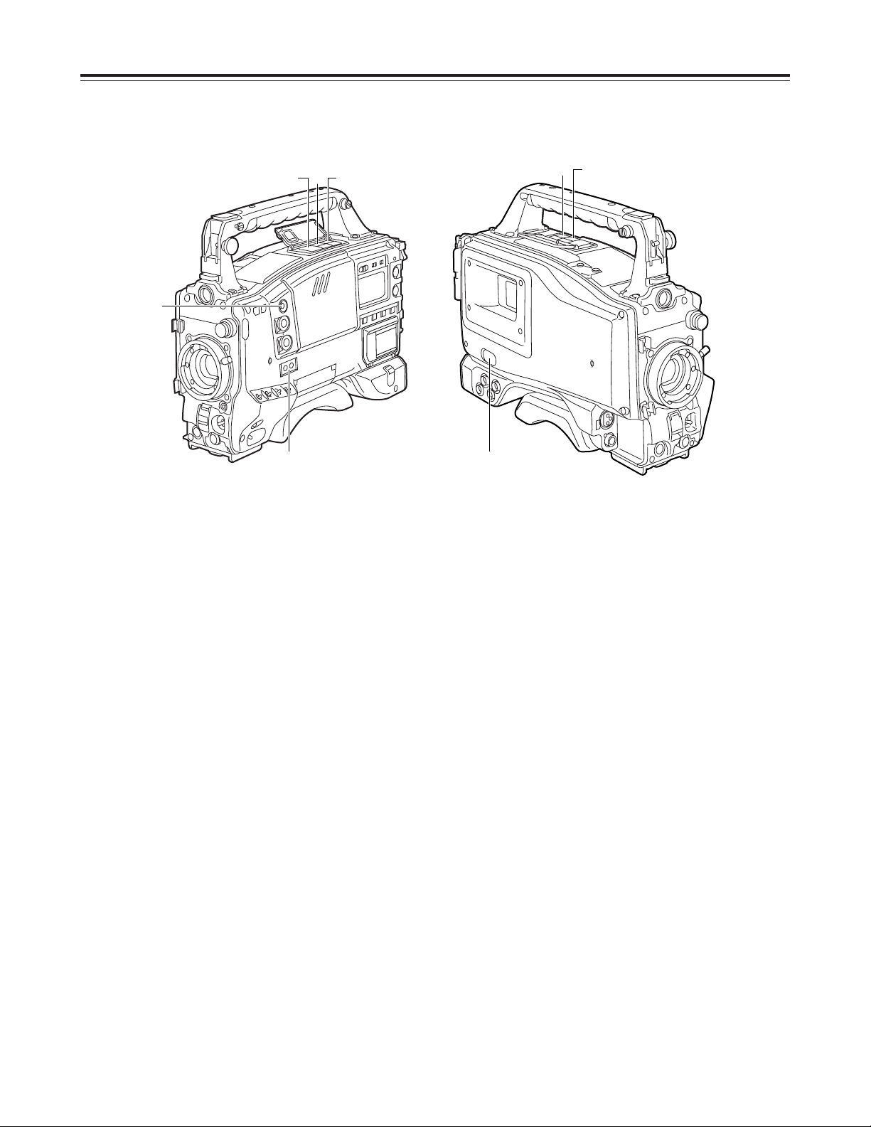
Power supply section
1 Battery mount
This is for attaching the Anton/Bauer battery pack.
2 DC IN (external power input) socket (XLR, 4P)
When operating this unit using an AC power
source, this socket is connected to the model AJB75 AC adapter (optional accessory).
3 BREAKER button
To protect the equipment, the circuit breaker is
tripped when an overcurrent flows inside the unit,
and the power is automatically turned off. Push this
button to the pushed-in position after performing
internal inspections and adjustments. If there is no
problem, the power will be turned back on.
4 POWER switch
ON
: Set here to turn on the power.
OFF
: Set here to turn off the power.
Parts and their functions
4
1
2
3
Page 10
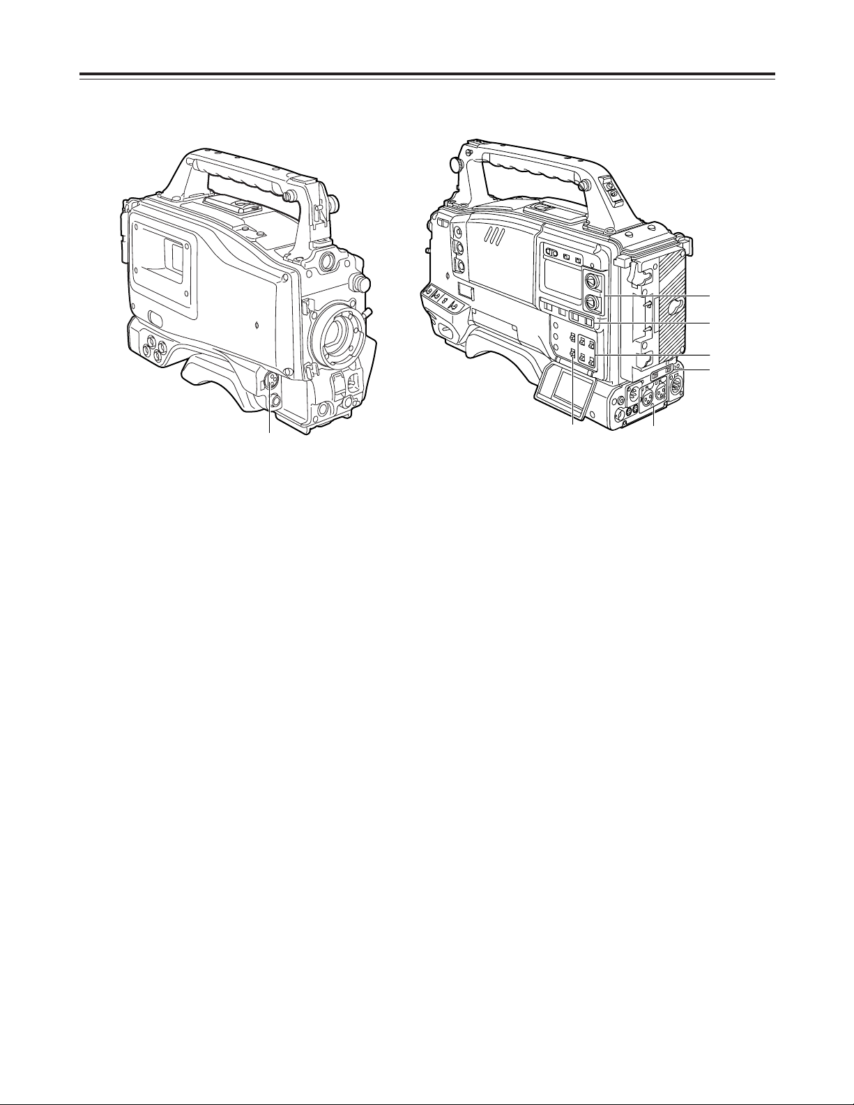
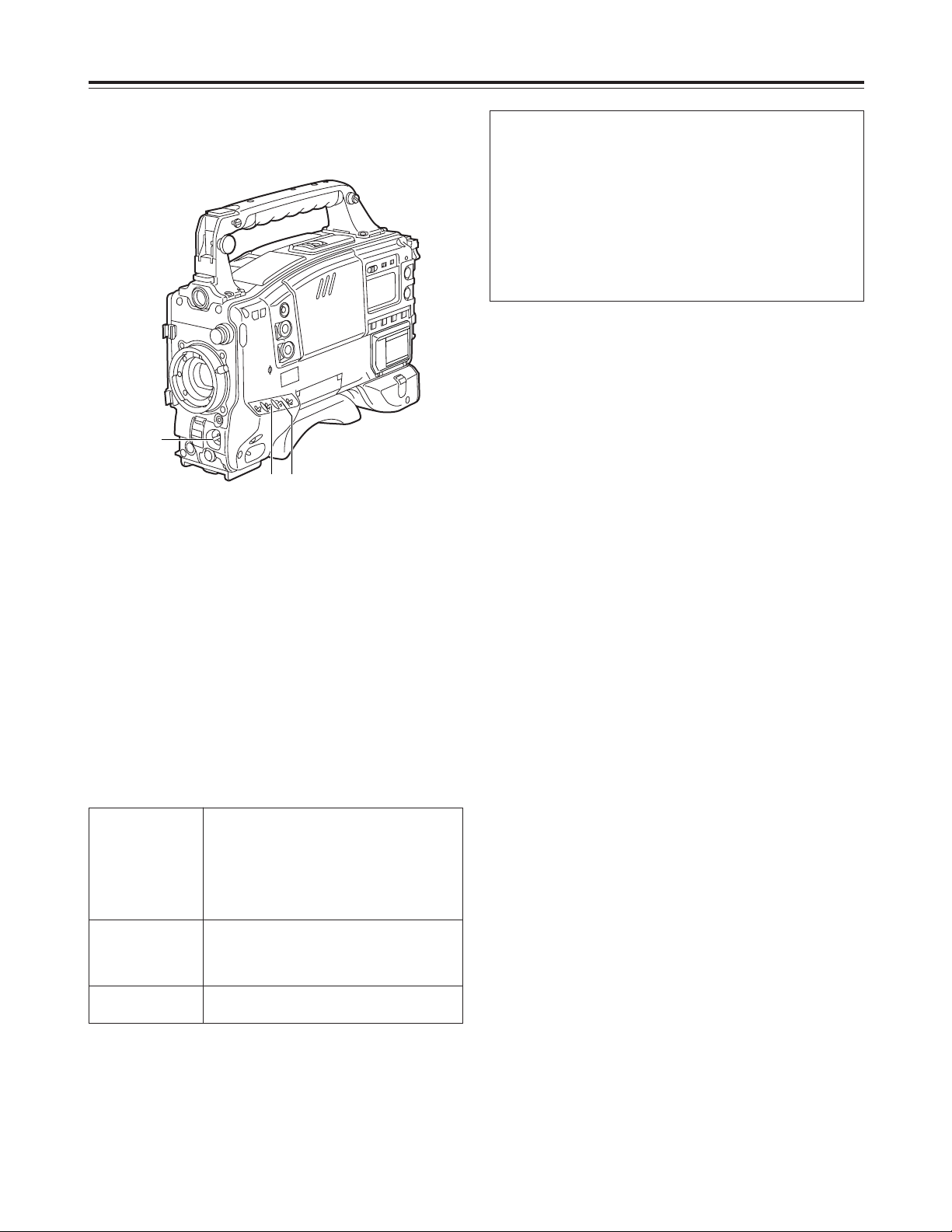
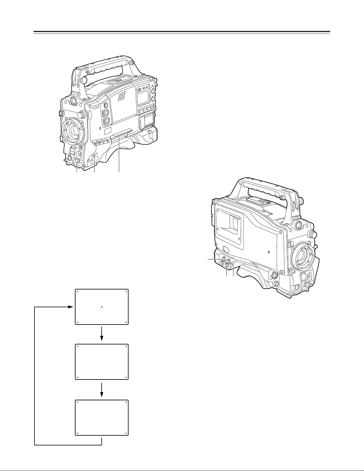
9 Shoulder pad
This pad can be adjusted to facilitate operation
when the unit is operated on the user’s shoulder.
The pad position can be moved forward or
backward when the two securing screws are
loosened.
: Mounting hook for tape measure
The tape measure used to measure the subject
distance is attached here.
<Note>
This hook is not to be used for the shoulder strap.
; Focus mark
This indicates the focus position of the CCD unit.
< Spacer to support extension unit
Future plans call for this connector to be used to
support some options.
10
Parts and their functions
Accessory mounting section
1 Hooks for attaching shoulder strap
Attach the ends of the accessory shoulder strap to
these hooks.
2 Light shoe
Use this to attach the video light, etc.
3 Lens mount (Bayonet type)
Use this to attach the lens.
4 Lever for securing lens
Insert the lens into the lens mount 3, and turn the
lens mount ring using this lever to secure the lens.
5 Lens mount cap
To remove the cap, push the lever for securing the
lens 4 up.
Keep the cap in place while the lens is not
attached.
6 Lens cable/microphone cable clamp
This clamp is for anchoring the lens cable or
microphone cable.
7 Tripod mount
Mount the tripod attachment (SHAN-TM700),
available as an optional accessory, when the unit is
to be anchored to the tripod.
8 LENS terminal (12-pin)
The connecting cable of the lens is connected here.
For details concerning the lenses that can be used,
consult your dealer.
1 2 :
1
6
6
3
4
7
5
; 9
<
8
Page 11
11
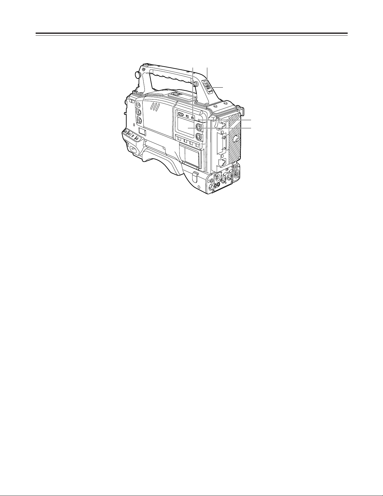
Audio function section (1)
1 MIC IN (microphone input) jack (XLR, 3-pin)
Connect the microphone (optional accessory) here.
The power for the microphone is supplied from this
jack.
2 AUDIO LEVEL CH1/CH2 (audio channel 1 & 2
recording level adjustment) controls
When the AUDIO SELECT CH1/CH2 switch 3 is
set to MAN, the recording level of audio channels 1
and 2 can be adjusted using these controls.
3 AUDIO SELECT CH1/CH2 (audio channel 1 & 2
automatic/manual level adjustment selector)
switch
This is used to select the method for adjusting the
audio levels of audio channels 1 and 2.
AUTO
: Set here for automatic adjustment.
MAN
: Set here for manual adjustment.
4 AUDIO IN (audio input selector) switch
This is used to select the input signals to be
recorded on audio channels 1 and 2.
FRONT
: The input signals supplied from the
microphone which has been connected to
the MIC IN jack 1 are recorded.
REAR
: The audio input signals supplied from the
audio component which has been
connected to the AUDIO IN CH1/CH2
connectors 5 is recorded.
5 AUDIO IN CH1/CH2 (audio input channel 1 & 2)
connectors (XLR, 3-pin)
An audio component or microphones are connected
here.
6 LINE/MIC/+48V (line input/mic input/mic input +
48V) selector switch
This is used to switch the audio input signals from
the audio component which has been connected to
the AUDIO IN CH1/CH2 connectors 5.
LINE
: The audio input signals from the audio
component serving as the line input are
selected.
MIC
: The audio input signals from the internal
power supply type of microphone are
selected. (The phantom mic power is not
supplied from the unit.)
+48V
: The audio input signals from the external
power supply type of microphone are
selected. (The phantom mic power is
supplied from the unit.)
7 CUE switch
CH1
: The audio CH1 signals are recorded on the
cue track.
MIX
: Audio CH1 and CH2 mixed signals are
recorded on the cue track.
CH2
: The audio CH2 signals are recorded on the
cue track.
<Note>
This switch can be made ineffective using the VTR
MAIN MENU. (See page 116)
Parts and their functions
6
5
7
1
2
3
4
Page 12
12
Audio function section (2)
8 AUDIO OUT connector (XLR, 5-pin)
This is connected to the audio component.
The sound of audio CH1 and the sound of audio
CH2 are output separately.
The switching of the recording sound and playback
sound is coupled with the setting of the MONITOR
OUT SDI switch. (No sound will be output when
the SDI switch is at OFF.)
9 DC OUT (DC power output) socket
This is the DC 12 V output socket. A current of
approximately 400 mA can be supplied.
: ALARM (warning alarm volume adjustment)
control
This is used to adjust the volume of the warning
alarms from the earphone which has been
connected to the speaker < or PHONES jack ?.
The warning alarms are not audible when this
control is at its lowest setting.
; MONITOR (volume adjustment) control
This is used to adjust the volume of all the sound
delivered through the speaker or earphone except
for the warning alarms.
The sound is not audible when this control is at its
lowest setting.
Parts and their functions
< Speaker
The EE sound during recording or the playback
sound during playback can be monitored through
this speaker.
The warning alarms are output in synchronization
with the flashing or lighting of the warning lamps
and warning displays.
The sound heard from the speaker is automatically
cut off when the earphone is connected to the
PHONES jack ?.
= MONITOR SELECT (audio channel selector)
switch
This is used to select the audio channels whose
sound is to be output from the speaker or
microphone.
CH1
: The audio CH1 signals are output.
1/2 : The audio CH1 and CH2 mixed signals or
stereo audio signals are output. However,
only mixed signals are output through the
speaker.
CH2
: The audio CH2 signals are output.
> MONITOR (audio selector) switch
This is used to select the sound which is to be
output to the earphone when “1/2” has been
selected by the MONITOR SELECT switch =.
ST
: The audio CH1 and CH2 stereo audio signals
are output.
MIX
: The audio CH1 and CH2 mixed audio signals
are output.
? PHONES (earphone) jack (mini jack)
When an earphone (optional accessory) is
connected, the sound selected by the MONITOR
switch > can be heard from the earphone. In
addition, the warning alarms relating to the unit’s
operations or statuses can be heard through the
earphone. An earphone which is capable of
delivering a sufficiently high volume is
recommended. However, when the earphone is
connected, the sound heard through the speaker <
will be automatically cut off.
<
=>
8
:
;
9?
Page 13
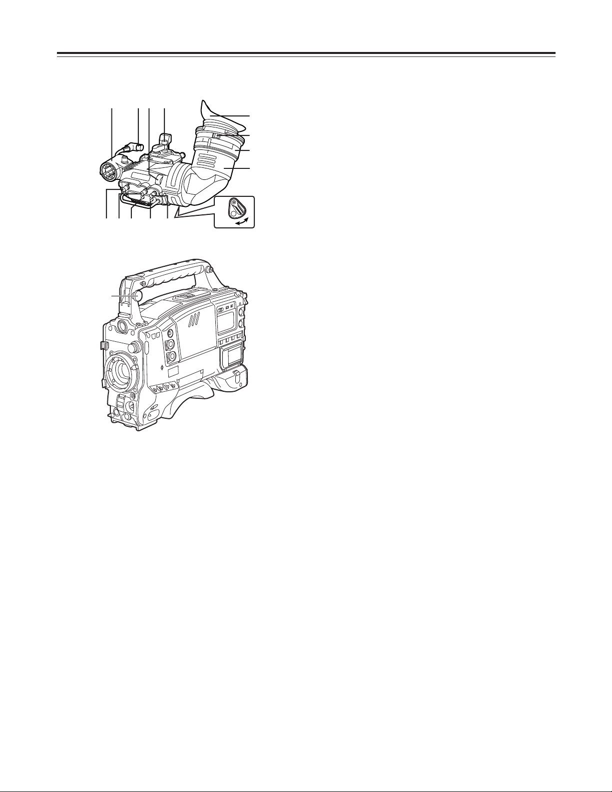
13
Viewfinder section
(Viewfinder pictured here is the AJ-HVF27P)
(For details concerning the viewfinder, refer to the
operating intructions of the viewfinder.)
Parts and their functions
ON
OFF
2
:
87<>
=
1
;
9
3645
3 TALLY switch
This is used to control the front tally lamp 7.
HIGH
: The brightness of the front tally lamp is
increased.
OFF
: The front tally lamp is turned off.
LOW
: The brightness of the front tally lamp is
reduced.
4 PEAKING control
This is used to adjust the outlines of the images
seen inside the viewfinder to make focusing easier.
Its adjustment does not affect the output signals of
the camera.
5 CONTRAST control
This is used to adjust the contrast of the picture
seen inside the viewfinder. Its adjustment does not
affect the output signals of the camera.
6 BRIGHT control
This is used to adjust the brightness of the picture
seen inside the viewfinder. Its adjustment does not
affect the output signals of the camera.
7 Front tally lamp
This lamp is activated when the TALLY switch 3 is
set to the HIGH or LOW position, and it lights while
the VTR unit is recording. It also flashes to provide
a warning display like the REC lamp inside the
viewfinder. The lamp’s brightness when it is lighted
can be selected using the TALLY switch (HIGH or
LOW).
8 Lever for securing the viewfinder in the
back/front and sideways directions
This lever is loosened when the viewfinder position
is to be adjusted in the back/front and/or sideways
directions.
9 Eyepiece
: Back tally lamp
This lamp lights while the VTR unit is recording. It
also flashes to provide a warning display like the
REC lamp inside the viewfinder.
When the lever is set to OFF, the back tally lamp is
hidden.
; Diopter adjustment ring
This is adjusted in line with the camera operator’s
diopter in such a way that the user can see the
image on the viewfinder screen most clearly.
< Connecting plug
= Locking ring
> Microphone holder
? Viewfinder stopper screw
To detach the viewfinder from the camera, first
loosen the stopper screw, and then remove the
viewfinder.
1 Viewfinder (optional accessory)
While recording or playback is underway, pictures
can be viewed through the viewfinder in black and
white. The warning displays concerning the unit’s
operation statuses and settings, messages, zebra
patterns and markers (safety zone markers and
center marker) can also be seen in the viewfinder.
2 ZEBRA (zebra pattern) switch
This is used to display the zebra pattern in the
viewfinder.
ON
: The zebra pattern is displayed.
OFF
: The zebra pattern is not displayed.
When the unit is shipped, the zebra pattern is set
so that an area of less than 85% is displayed with a
video level of at least 80% or so.
The required area of zebra pattern can be
displayed by setting the ZEBRA 1 DETECT,
ZEBRA 2 DETECT and ZEBRA 2 items on the
FILM (CAM) MAIN MENU 2 screen.
?
Page 14
14
2 Synchro scan adjustment switches
These switches become effective when the shutter
switch 7 is set to ON and SYNCHRO SCAN 2 is
selected. They are used to adjust the synchro scan
speed.
When the “–” switch is pressed, the shutter speed is
reduced; conversely, when the “+” switch is
pressed, it is increased.
During personal computer monitor shooting, etc.
adjust these switches to the positions where the
horizontal bar noise inside the viewfinder is
decreased.
3 WHITE BAL (white balance memory selector)
switch
PRST
: Set the switch to this position in cases where
there is not enough time to adjust the white
balance. The TUNGSTEN (3200 K) white
balance value is stored in the memory.
This can be changed to DAY LIGHT (5600
K).
A or B
: When the AUTO W/B BAL switch 6 is set to
AWB, the white balance is automatically
adjusted to match the setting position of the
CC FILTER control 1, and the adjustment
value is stored in memory A or memory B.
When the CC FILTER control and the WHITE BAL
switch are set to the same positions as they were
when adjustment was performed, the adjustment
value stored in the memory is recalled, and the unit
is automatically adjusted to the white balance that
corresponds to this value.
If this switch setting is changed while the menu
display mode is set to “3” (default setting), the new
setting will appear at the WHITE BAL switch display
position on the viewfinder screen.
(Example: “A”)
Shooting (recording)/playback
function section (1)
1 CC FILTER/ND FILTER (filter selector) control
This is used to select the filter to match the light
source which is illuminating the subject. If the
control setting is changed while the menu display
mode is set to “3” (default setting), the new setting
will appear at the setting change message display
area of the viewfinder screen.
OThe two types shown above are provided for filter
combinations.
$ Control settings and filter selection
Parts and their functions
$ Examples of filter selection
Shooting conditions
CC filter
Sunrise, sunset, inside a studio
B (3200 K)
ND filter
1 (CLEAR)
Outdoors under a clear sky
C (4300 K) or
D (6300 K)
2 (1/4 ND) or
3 (1/16 ND)
Outdoors under cloudy or rainy
skies
D (6300 K)
1 (CLEAR) or
2 (1/4 ND)
Snowscapes, high mountains,
seashores or other perfectly clear
scenery
C (4300 K) or
D (6300 K)
3 (1/16 ND) or
4 (1/64 ND)
CC FILTER control (large
diameter) setting
CC filter selection
A
Cross filter
B
3200 K
C
4300 K
D
6300 K
ND FILTER control (small
diameter) setting
ND filter selection
1
CLEAR (Transparent)
2
1/4 ND
3
1/16 ND
4
1/64 ND
3
1
2
<Note>
The color temperatures shown above are those when the
LIGHTING item is set to TUNGSTEN or the D5600K item is set to
OFF on the CAMERA SETTING screen of FILM (CAM) MAIN
MENU 1.
Page 15
15
Shooting (recording)/playback
function section (2)
4 OUTPUT (output signal selector)/AUTO KNEE
switch
This is used to select the video signals which are to
be output from the camera unit to the VTR unit,
viewfinder and video monitor.
The AUTO KNEE function can be used when the
pictures shot by the camera are selected.
The operation of the AUTO KNEE function can be
selected using the AUTO KNEE SW item on the
CAMERA SW MODE screen of FILM (CAM) MAIN
MENU 2.
(The factory setting of the AUTO KNEE function is
OFF.)
5 GAIN (gain selector) switch
This is used to select the gain of the video amplifier
in accordance with the lighting status during
shooting. The gain values corresponding to the L,
M and H settings are specified by the setting menu
ahead of time.
If this switch setting is changed while the display
mode is set to “3,” the new setting will appear at the
gain display position on the viewfinder screen.
(Example: “12 dB”)
6 AUTO W/B BAL (automatic white balance/black
balance adjustment) switch
AWB
: This is selected when the white balance is to
be adjusted automatically. When the WHITE
BAL switch 3 is set to “A or B” at this time,
the adjusted value will be stored in memory A
or memory B.
ABB
: This is selected for automatically adjusting the
black balance.
The adjusted value is stored in a dedicated
memory.
Black shading is automatically corrected when
SHD and ABB SW CTRL on the OPTION
screen of FILM (CAM) MAIN MENU 4 are set
to ON and the AUTO W/B BAL switch is
pressed continuously for 8 seconds or more
on the ABB side.
Parts and their functions
$ OUTPUT/AUTO KNEE switch setting position
BARS
Color bar signals are output.
The AUTO KNEE circuit is not activated.
Use this position in the following
circumstances.
OWhen the video monitor is to be adjusted
OWhen the color bar signals are to be
recorded
CAM.
AUTO KNEE OFF
The pictures shot by the camera are output.
The AUTO KNEE circuit is not activated.
MANUAL KNEE is selected as the default
setting.
CAM.
AUTO KNEE ON
The pictures shot by the camera are output.
The AUTO KNEE circuit is activated.
AUTO KNEE function
If the level is adjusted to people or scenery for shooting when the
background is very bright, the background becomes subject to
white-out, causing the buildings and scenery in the background to
be blurred. When the AUTO KNEE function is activated in a
situation like this, the background can be reproduced distinctly.
This function is very effective for shooting in the following
situations.
OWhen shooting people in the shade under a clear sky
OWhen shooting people inside a vehicle or a building and
outdoor scenery seen through windows at the same time
OWhen shooting scenes with a high contrast
<Note>
When white balance or black balance are being
automatically adjusted and the switch is pressed
again to either the AWB side or to the ABB side, the
automatic adjustment for the side pressed will be
stopped.
The adjusted value in this case is the value before
automatic adjustment was performed.
6
5 4
Page 16
16
Shooting (recording)/playback
function section (3)
7 SHUTTER switch
This is set to ON when the electronic shutter is to
be used. When the SEL side is pressed, the
shutter speed and mode display are changed in the
range which was set ahead of time in the setting
menu.
If this switch setting is changed while the display
mode is set to “2” or “3,” the new setting will appear
at the shutter display position on the viewfinder
screen.
(Example: “: 1/120”, “: 50%”, “: 180d”)
8 ECU REMOTE (remote control) connector (6-
pin)
The AJ-EC3 extension control unit (optional
accessory) is connected here.
<Note>
Before connecting or disconnecting the remote
control cable, be absolutely sure to set the POWER
switches on the unit and extension control unit to
the OFF position.
9 HD SDI OUT connector (BNC)
The HD SDI signals (video and audio) for the
monitor in accord with the position of the MONITOR
OUT SDI switch : are output from here.
When the SDI switch is at “EE/PB,” the EE video
and EE audio signals will be output during
recording and the playback video and playback
audio signals will be output during playback.
When the SDI switch is at “EE,” the camera video
signals are output at all times.
When the CHARACTER switch is set to ON while
performing the menu settings, it is possible to
superimpose the setting menus onto the pictures
being shot so that they can be checked on the
monitor screen.
The user’s bit is also output from the HD SDI OUT
connector.
The active frame count is output to the four higher
digits of the user’s bit. The count is reset to zero
each time recording starts, and the count is
incremented with each active frame.
The active frame information is output to the lowest
digit of the user’s bit while the frame rate
information is output to the third and fourth lower
digits.
<Note>
In order for the time code that matches the
playback time code, which is output from the HD
SDI OUT connector, to be output from the TC OUT
connector, set the SDI switch to “EE/PB,” and
select “TCG/TCR” as the TC OUT item setting on
the TC/UB screen.
Parts and their functions
9
79
8
Page 17
17
Shooting (recording)/playback
function section (4)
: SDI switch
This is used to select the video and audio signals
which are to be output from the HD SDI OUT
connector and the audio signals which are to be
output from the AUDIO OUT connectors.
EE/PB
: During playback, the playback video and
playback audio signals are output; in all
other modes, the EE video and EE audio
signals are output.
EE
: The EE video and EE audio signals are
output at all times.
OFF
: Signal output is stopped. (This serves
effectively as a power-conserving mode.)
<Notes>
OWith the settings at shipment, this function does
not work at the OFF position when a cable is
connected to the HD SDI OUT connector. For
further details, refer to the FUNCTION screen
(page 112) of the VTR menu.
During recording, the HD SDI OUT output
signals cannot be switched from ON to OFF or
vice versa. The status set prior to the
commencement of recording is maintained.
OWhen the frame frequency has been set to 60.00
Hz, the audio signals which are output from the
HD SDI OUT connector can be controlled on the
MIC AUDIO screen of VTR MENU.
However, it should be borne in mind that some
products may not be able to process properly the
audio signals which are output from the HD SDI
OUT connector at this 60.00 Hz frequency
setting.
For details, consult your dealer.
; CHARACTER switch
This controls whether the characters are to be
superimposed onto the pictures which are output
from the HD SDI OUT connector.
ON
: The characters are superimposed.
OFF
: The characters are not superimposed.
< VTR START button
When this is pressed, recording starts; when it is
pressed again, recording stops.
This button functions in the same way as the lens
VTR button.
= VTR SAVE/STBY (tape protection) switch
This is used to select the power supply mode when
the VTR has temporarily stopped recording (REC
PAUSE mode).
SAVE
: This is the tape protection mode. The
cylinder is stopped in the half-loading status.
Less power is consumed than at the STBY
position, and the operating time provided by
the battery is prolonged. Compared with the
STBY position, it takes longer for recording to
commence after the VTR START button <
has been pressed.
When the switch is set to this position, the
VTR SAVE lamp inside the viewfinder lights.
STBY
: At this position, recording is commenced as
soon as the VTR START button is pressed.
<Note>
When the prescribed amount of time has elapsed in
the STBY mode, the unit is automatically set to the
SAVE mode. To return the unit to the STBY mode,
set the VTR SAVE/STBY switch to SAVE, and then
again to the STBY position.
Parts and their functions
= ;
<
:
Page 18
18
Shooting (recording)/playback
function section (5)
C PLAY/PAUSE button
This is pressed to view the playback picture on the
viewfinder screen or using a color video monitor.
The button’s lamp comes on during playback.
When it is pressed during playback, the unit is set
to pause in the playback mode (PLAY PAUSE), and
the button’s lamp flashes. If the unit is left in the
pause mode for two minutes, it automatically
changes to the stop (STOP) mode.
D STOP button
This is pressed to stop the tape travel.
E EMERGENCY screw (inside rubber cap)
If the cassette does not eject even when the EJECT
button is pressed, use a screwdriver or similar
implement to push and turn the EMERGENCY
screw at the same time: this will cause the cassette
to be ejected.
Parts and their functions
> MODE CHECK button
While this button is held down, the camera’s setting
mode is shown in the viewfinder.
This does not affect the output signals of the
camera.
? USER 1 and USER 2 buttons
A user setting can be allocated to each of these
buttons using the setting menu.
When a button is pressed, the user setting mode
allocated to it is selected.
When the button is pressed again, the selected
mode is released.
@ EJECT button
This is pressed to insert or eject the cassette.
A REW button
This is pressed to rewind the tape. The button’s
lamp comes on during rewinding.
When it is pressed during playback, the tape will be
reviewed (rewound and played back) at about twice
the regular speed while the button is held down.
B FF button
This is pressed to fast forward the tape. The
button’s lamp comes on during fast forwarding.
When it is pressed during playback, the tape will be
cued (fast forwarded and played back) at about
twice the regular speed while the button is held
down.
C
D
A
? E
B
@
>
Page 19
19
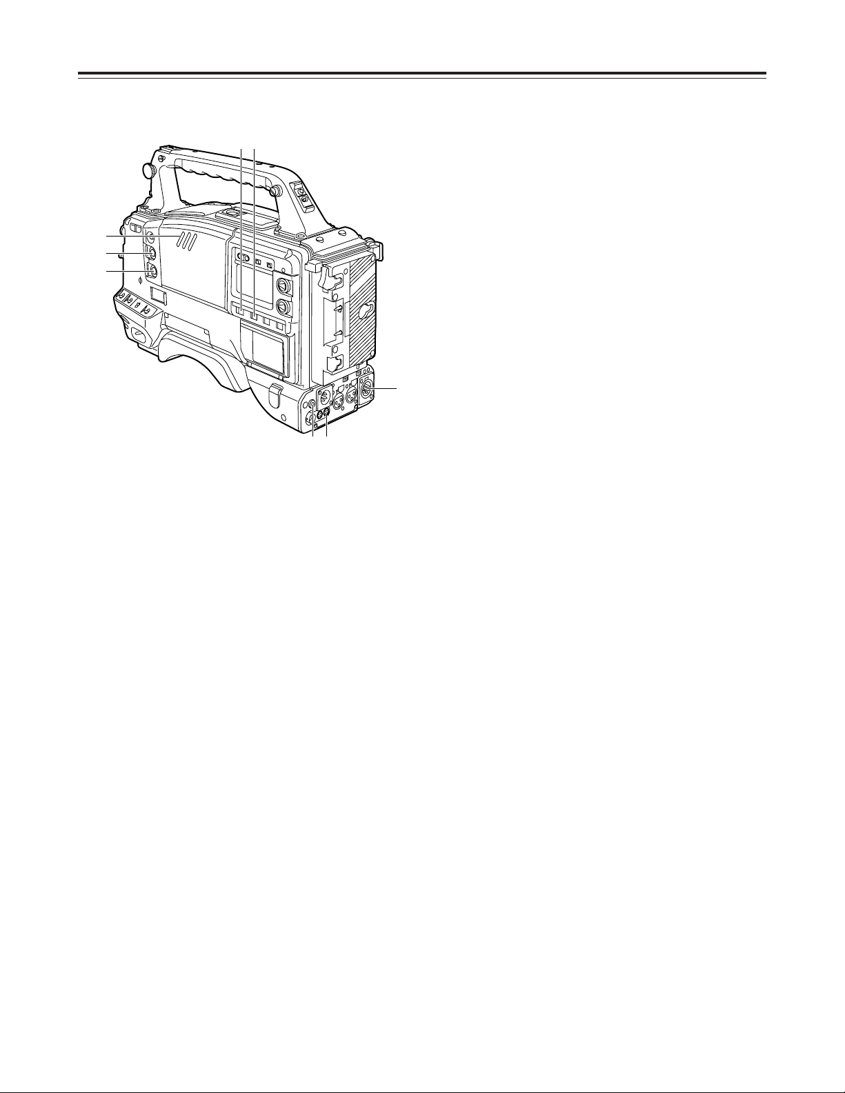
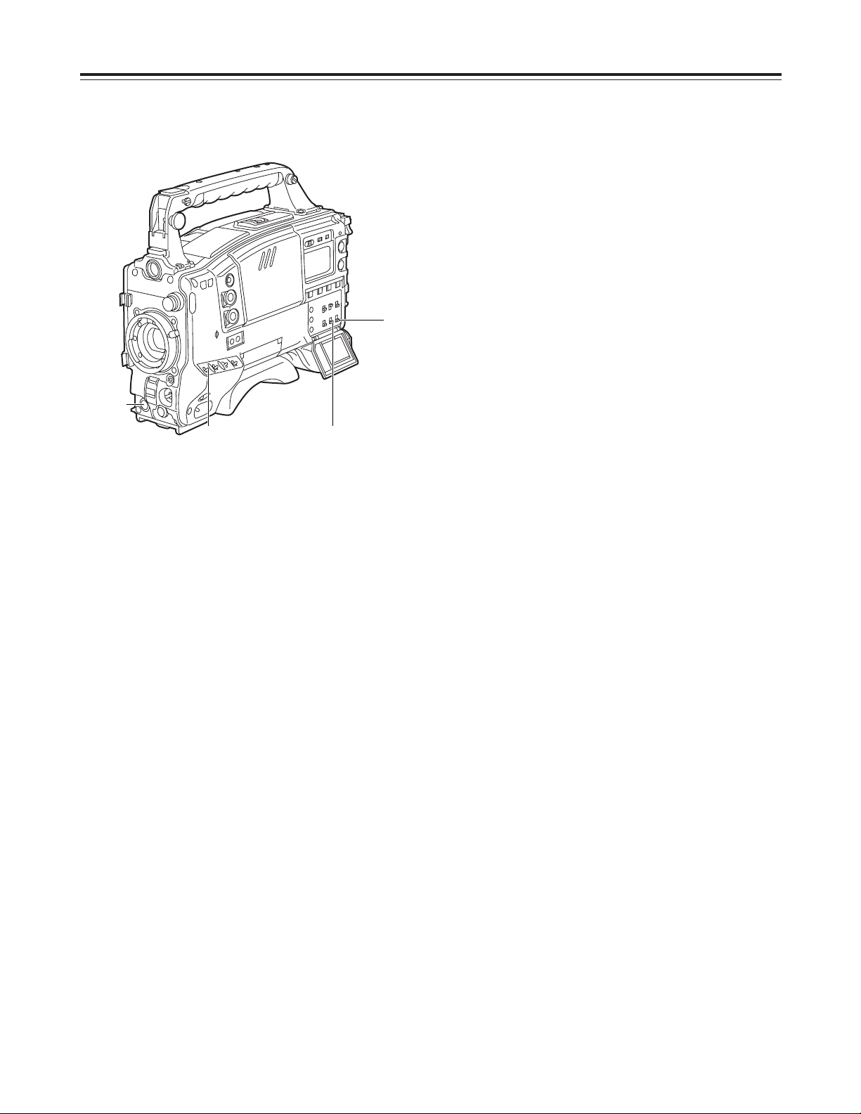
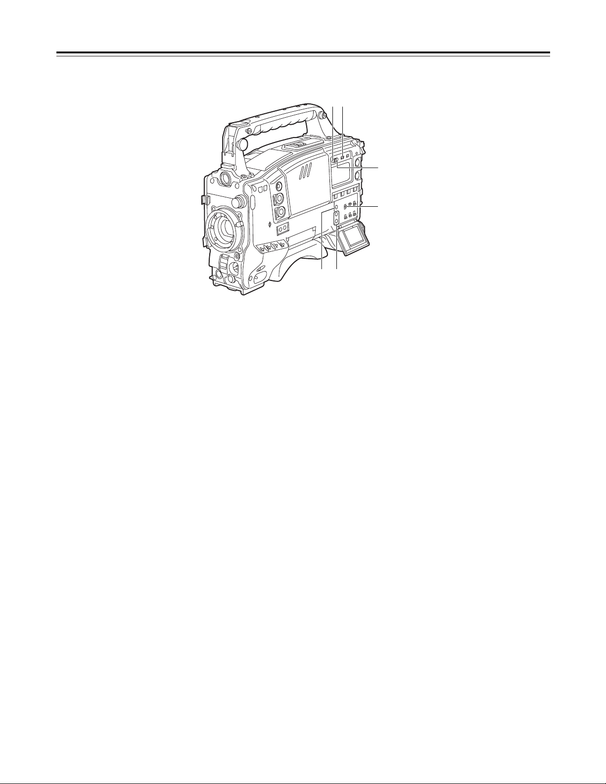
Warning/status display section
1 Back tally lamp (unit)
When the back tally switch 2 is set to ON, this
lamp serves the same function as the front tally
lamp in the viewfinder.
2 Back tally switch
This is used to control the unit’s back tally lamp 1.
ON
: The unit’s back tally lamp is operational.
OFF
: The unit’s back tally lamp is not operational.
3 WARNING lamp
When a problem of some form or other occurs
within the VTR unit, this lamp flashes or lights.
4 LIGHT switch
ON
: The display window 5 is illuminated.
OFF
: The illumination of the display window is
turned off.
5 Display window
This displays the alarms, remaining battery charge,
audio levels, time data, etc. relating to the VTR unit.
Parts and their functions
3
5
14
2
Page 20
20
1AB 0dBCZ73
¢¢¢¢ VTR USER MENU ¢¢¢¢
¢¢¢¢ FILM USER MENU ¢¢¢¢
Menu operation section
1 Setup card insertion slot
The setup card, available as an optional accessory,
is inserted into this slot.
2 MENU button
When this is pressed, the camera unit’s user menu
screen, which was set at the time of shipment,
appears.
When it is pressed again, the VTR unit’s user menu
screen appears.
When it is pressed once more, the menu screen
display is cleared.
The selection of the menu for the user menu can be
changed on the USER MENU SELECT screen.
3 JOG dial button
When this dial button is turned while the menu
screen is displayed, the cursor is moved to each of
the setting items.
The menu items are set by operating this dial
button.
There are two types of menus, MAIN and SUB, and
each menu is displayed on a page-by-page basis.
The menu configuration can be changed to suit the
desired objective.
For details on the menu operation method, refer to
“Menu operations” on pages 84 to 86.
Parts and their functions
When the power is turned on
Status display
Camera unit’s user
menu
VTR unit’s user
menu
Press the MENU
button.
Press the MENU
button.
Press the MENU button.
Time code related section (1)
1 GENLOCK IN connector (BNC)
Supply the analog HD reference signal to this
connector for gen-locking the camera unit or when
externally locking the time code.
<Note>
Enter the reference signal of the same frame
frequency (59.94 Hz or 60.0 Hz) as the unit.
2 TC IN connector (BNC)
Supply the time code which will serve as the
reference to this connector when externally locking
the time code.
3 TC OUT connector (BNC)
To lock the time code of an external VTR to the
unit’s time code, connect this connector to the time
code input (TC IN) connector on the external VTR.
3 2 1
3 2
1
Page 21
21
7 “+” button, “–” button
These are used to increment or decrement by 1 the
figure in the digit which was made to flash by the
SHIFT button 8 when the time code or user’s bit is
to be set.
8 SHIFT button
This causes the digit to be set to flash when the
time code or user’s bit is to be set.
9 TCG (time code selector) switch
This is used to set the running mode of the built-in
time code generator.
F-RUN
: Set here to have the time code run all the
time regardless of the VTR’s operation.
This position is used to align the time code
with the time or externally lock the time
code.
SET
: Set here when the time code or user’s bit is
to be set.
R-RUN
: Set here to have the time code run only
during recording.
The time code on the tape with scene-toscene continuity is recorded continuously.
Time code related section (2)
4 HOLD button
The time data display of the counter display section
which was on the screen at the moment when this
button is pressed is held. (However, the time code
generator keeps running.) When the button is
pressed again, the hold status is released.
It is used, for instance, to find out the time at which
a particular scene was shot.
<Note>
If the HOLD button is pressed and held down while
the DISPLAY switch 6 has been set to UB,
“HOLD” on the counter display flashes, and the
button functions to display the VITC user’s bit
information recorded in the video AUX area on the
counter display section.
5 RESET button
This is used to reset the time data on the counter
display section to “00:00:00:00.” If it is pressed
while the TCG switch 9 is at the SET position, the
time code data and user’s bit data are respectively
reset to “00:00:00:00.”
6 DISPLAY switch
This is used to display the time code, CTL or user’s
bit on the counter display section depending on the
setting positions of this switch and the TCG switch
9.
UB
: The user’s bit is displayed.
TC
: The time code is displayed.
CTL
: CTL is displayed.
Parts and their functions
46
78
9
5
Page 22
Removal lever
Battery pack
22
Power supply
Using the Anton/Bauer battery pack
A battery pack or an AC power source can be used as
this unit’s power supply.
To use the battery pack, there is a choice of
makes of batteries below, namely:
OAnton/Bauer
OIDX
OSony
<Note>
Batteries of other makes can also be supported by
changing the setting menu but no guarantees are
made for the system when they are actually used with
this unit.
Before using the battery pack, recharge the battery
using the battery charger.
(For details on the recharging method, refer to the
operating instructions of the battery concerned.)
<Note>
An intelligent battery system and ultra light system are
supported.
The remaining battery charge displayed inside the
viewfinder is usually shown as a percentage of the full
charge, but when the battery charge is nearly
completely dissipated, the percentage display is
replaced with a voltage display.
1
Attach the battery pack.
Insert the pack in the direction shown by the
arrows, and then slide it into position.
2
To detach the battery, pull the battery mount
removal lever all the way down, and slide the
battery pack in the direction shown by the arrow.
Page 23
23
Power supply
Using the BP-90 type battery pack
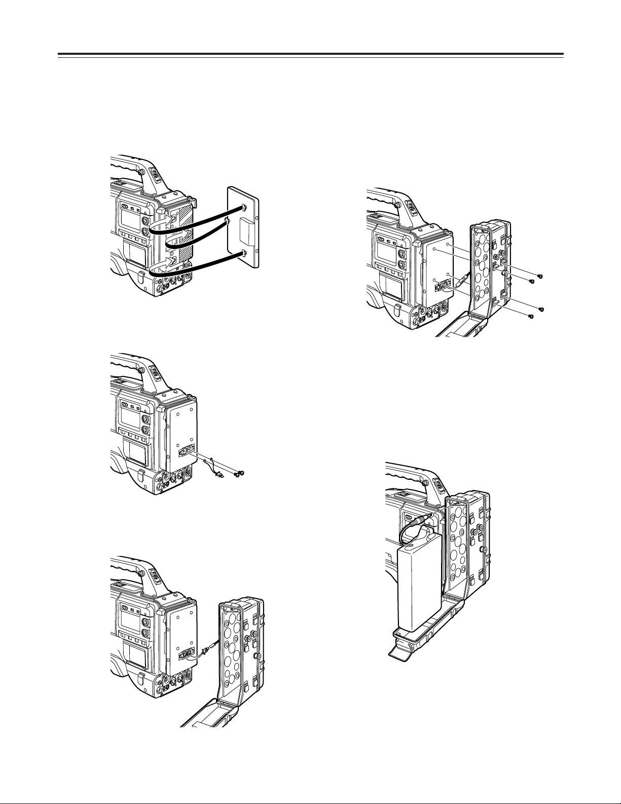
<Notes>
ODo not pull the rubber cap forcefully.
OWhen mounting the battery case, take care not to
pinch the connecting cord.
4
Attach the AU-M402H battery case.
Open the battery case cover, and raise it above the
rubber cap: screw holes will now be visible.
Tighten the screws using a screwdriver, then
attach the case to the NP/BP adapter plate and
tighten the screws fully.
5
Connect the plug on the battery pack to the
connector inside the case, and insert the battery
pack.
<Note>
Before connecting or disconnecting the plug, be
absolutely sure to turn off the unit’s power.
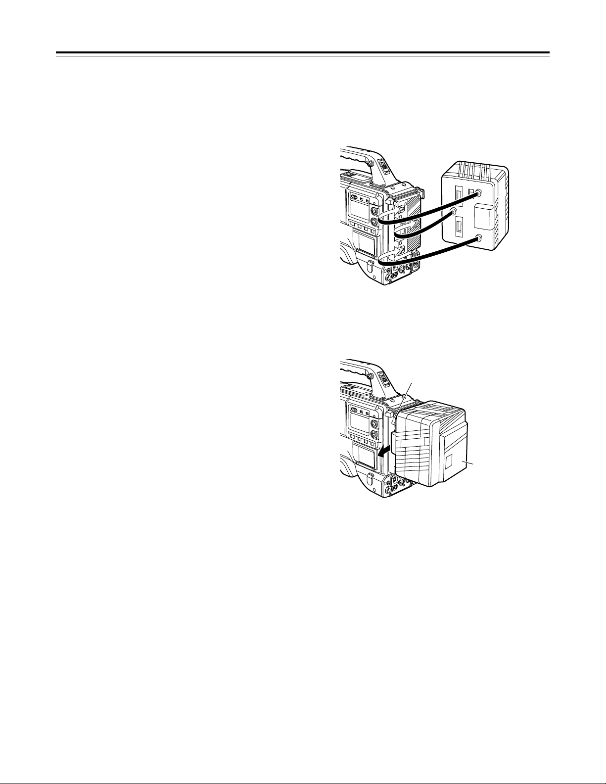
3
Connect these connectors with the connector on
the AU-MA402H battery case.
1
Attach the NP/BP adapter plate.
Insert it in the direction shown by the arrows, and
slide it into place.
2
Attach the connectors provided with the NP/BP
adapter plate to the positions shown in the figure.
Page 24
24
Power supply
Using the Sony NP-1/BP-90 battery
pack
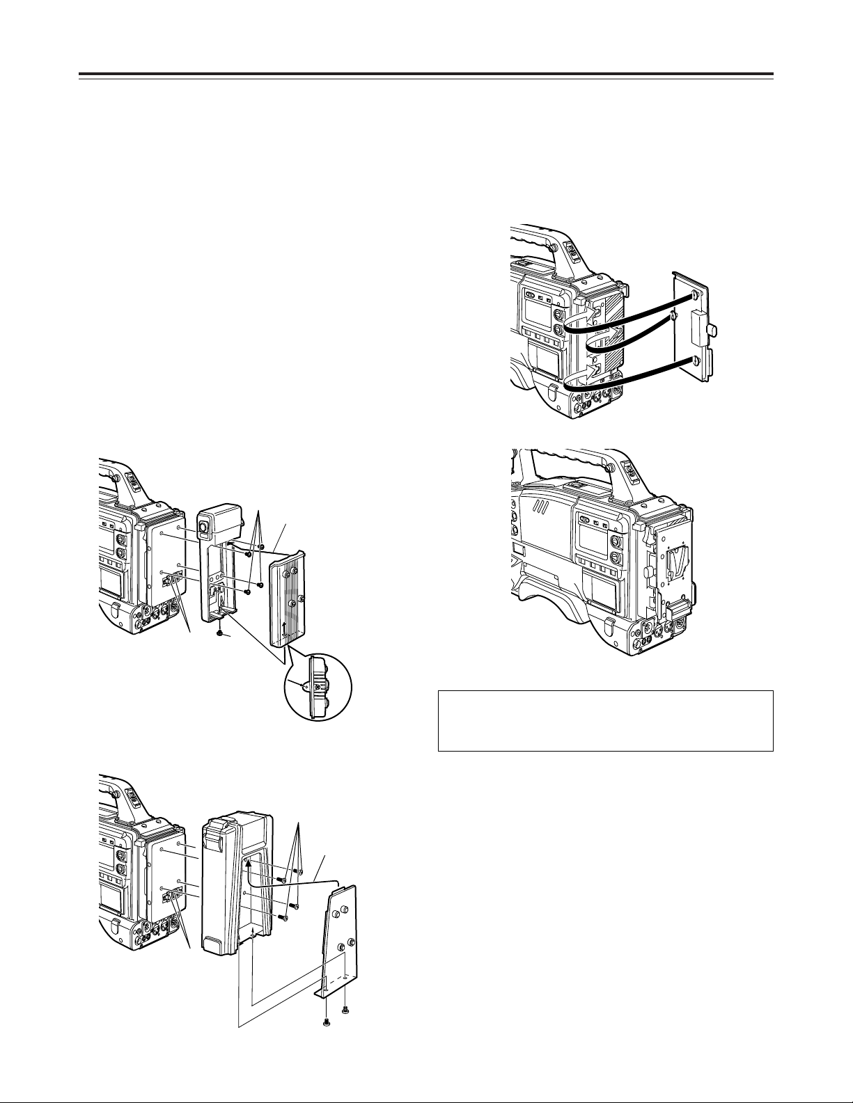
Attach the Sony battery holder. As shown in the
figure, attach the battery case with the cover detached
and then the detached cover.
1 Tighten the mounting screws.
2 Tighten the power contact screws.
3 Insert the top of the detached cover in the direction
shown by the arrows.
4 Align the holes in the bottom of the cover (metal
part) with the holes at the bottom of the case, and
use the screws to attach the case.
<Note>
When mounting the battery holder, take care not to
pinch the connecting cord.
Using the V-mount type battery
pack
1
3
4
2
Battery case for NP-1
Battery case for BP-90
2
1
3
4
Attach the V-mount adapter plate.
Insert it in the direction shown by the arrows, and slide
it into place.
Please consult your local dealer for any questions
regarding the NP/BP adapter plate or V-mount
adapter plate.
Page 25
25
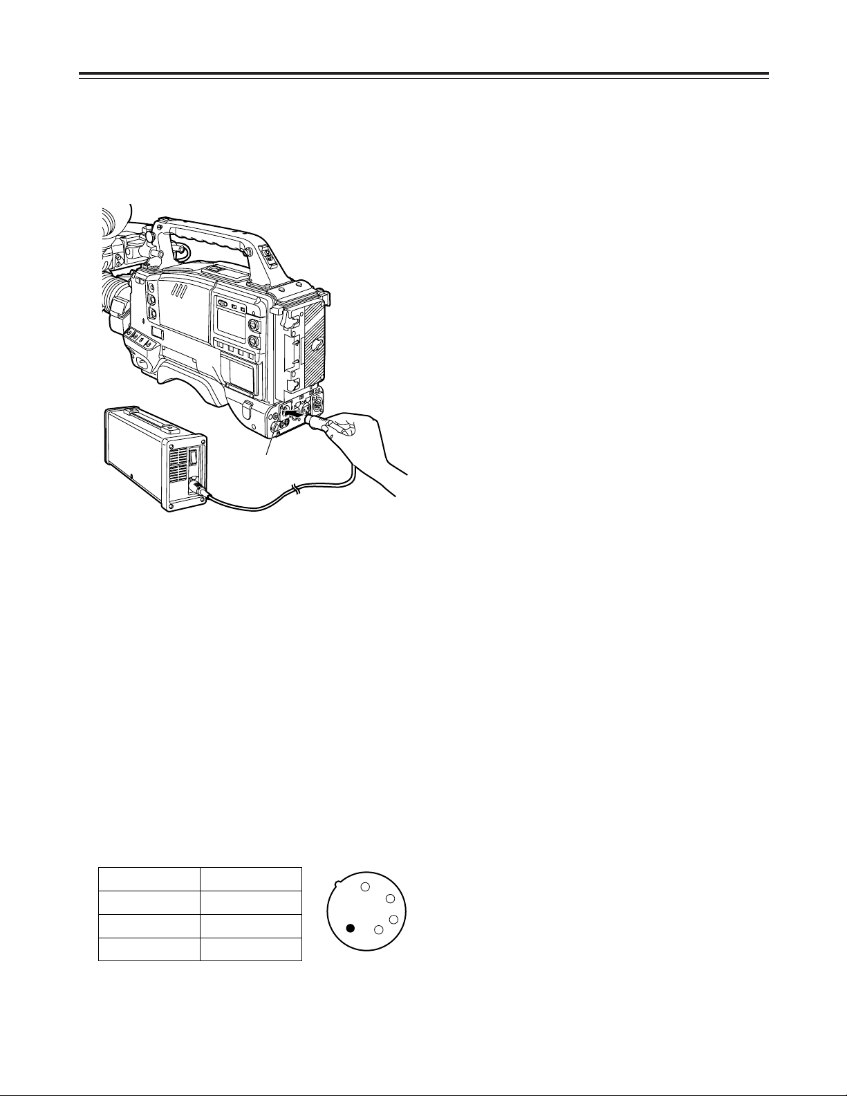
Using an AC power supply
When the AJ-B75 AC adapter is used
<Notes>
OCheck the pin signals of the DC IN socket when
using an external power supply other than the AJB75 AC adapter. (DC 12 V, 8.5 A)
OPower from the AC adapter takes precedence when
both a battery pack and AC adapter have been
connected.
OWhen using the AC adapter, be absolutely sure to
first set the power of the AC adapter to ON and
then set the unit’s power switch to ON.
If the power is turned on in the reverse sequence,
the output voltage of the AC adapter will rise
gradually, and the unit may malfunction as a result.
1
2
3
4
1
Connect the DC OUT connector on the AJ-B75 AC
adapter to the DC IN socket on the unit.
2
Set the power of the AC adapter to ON.
3
Set the unit’s power switch to ON.
Pin no. Signal
1 GND
2, 3
==
4 +12 V
Power supply
DC IN socket
Page 26
26
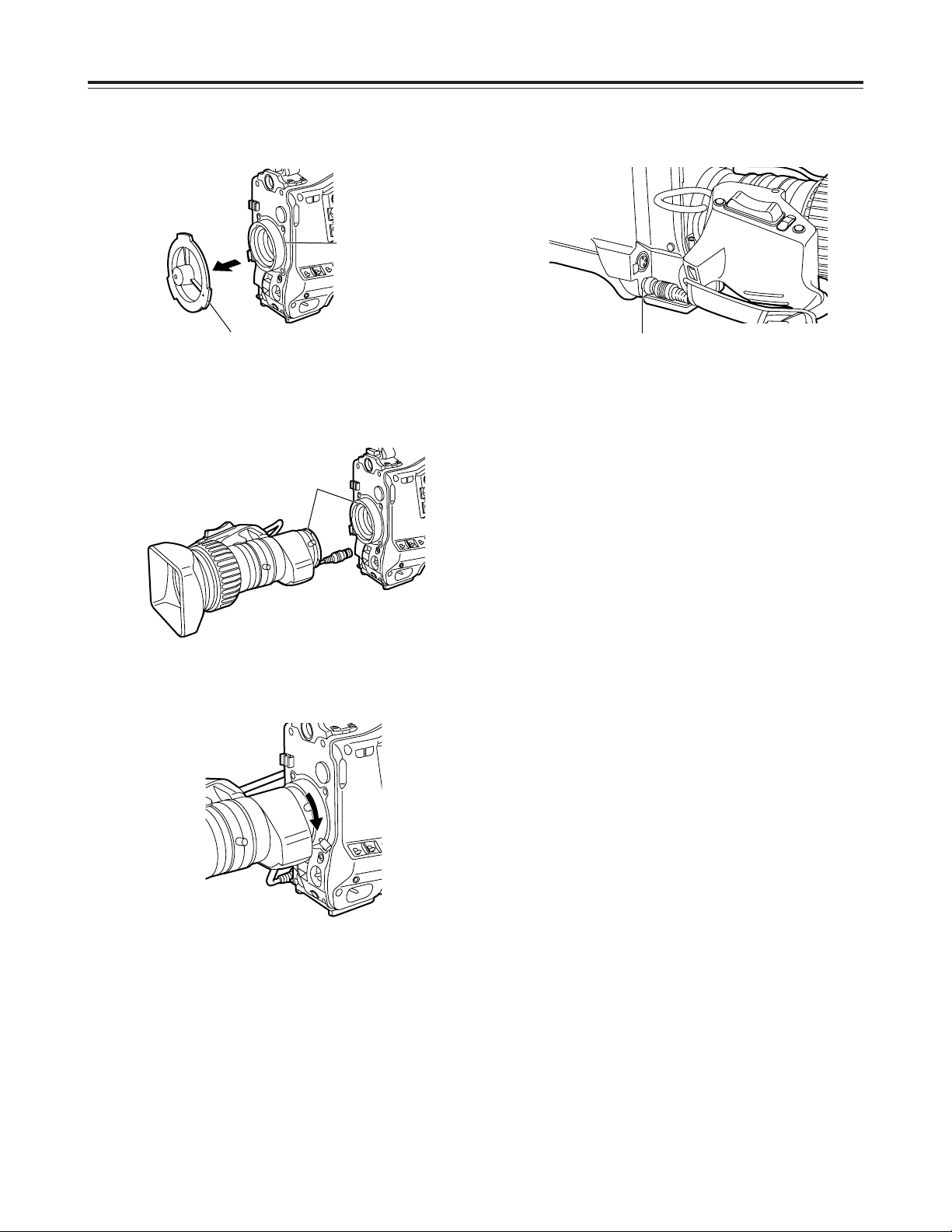
Attaching the lens
1
Raise the lever for securing the lens, and detach
the mount cap.
2
Align the center mark of the lens with the groove in
the top center of the lens mount, and attach the
lens.
3
Push down the lever for securing the lens to
secure the lens.
4
Push the cable into the cable clamp, and connect it
to the LENS socket.
<Notes>
OFor details on handling the lens, refer to the
operating instructions which accompany the lens.
OThe following lens adjustments and camera
adjustments may be necessary depending on the
lens mounted.
1. Lens flange back adjustment
2. Lens auto iris operating speed adjustment
3. Lens white shading adjustment (performed on
the unit)
Lever for securing
the lens
Mark
LENS socket
Mount cap
Page 27
27
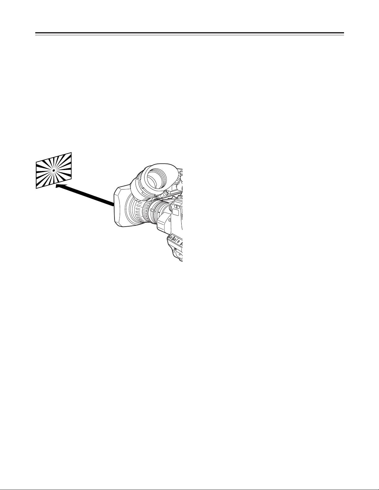
Adjusting the lens flange
If the subject is not focused properly in the telephoto
and wide-angle modes during zoom operations, adjust
the flange back (distance from the lens mounting
surface to the image-forming surface).
Once this adjustment is done, it need not be redone
unless the lens is replaced.
Adjustment method
1
Attach the lens to the camera.
At this stage, do not forget to connect the lens
cable.
2
Set the lens aperture to manual and open the
aperture.
3
Set the lighting in such a way that the appropriate
video output level is achieved at a distance of
about 3 meters away from the chart used for the
flange back adjustment.
If the video level is too high, use the filters and
shutter.
4
Loosen the screw securing the F.f (flange focus)
ring.
<Note>
On some lenses, this may be marked as F.b
(flange back) ring.
5
Set the zoom ring to the telephoto position either
manually or electrically.
6
Shoot the chart used for the flange back
adjustment, and turn the distance ring to adjust the
focus.
7
Set the zoom ring to the wide-angle position, and
turn the F.f ring to adjust the focus.
Take care not to move the distance ring during this
process.
9
Tighten the screw securing the F.f ring.
8
Repeat steps 5 to 7 until the focus is adjusted at
both the telephoto and wide-angle positions.
<Note>
For details on the adjustment method and lens
positions, refer also to the operating instructions that
accompany the lens.
Approx. 3
meters
Page 28
28
Adjusting the white shading
Follow the procedure outlined below when the white
shading needs to be re-adjusted.
Adjustment method
<Notes>
OThe method below can be used for the white
shading adjustments with most lenses. However,
with some very special lenses, a different
adjustment method may be necessary.
OEven when the white shading has been adjusted,
tinting may occur in the vertical direction near the
lens aperture open position. This is a phenomenon
which is inherent to lenses and optical systems and
is not indicative of malfunctioning.
SHUTTER: OFF
GAIN: L (0 dB)
JOG dial button
MENU button
1
Attach the lens to the camera.
At this stage, do not forget to connect the lens
cable.
2
Set the electronic shutter to OFF, and set the gain
to “L (0 dB).”
3
If the lens is provided with an extender, disengage
the extender function.
4
1 Perform the menu operations (pages 84 to 86),
and display the “VF DISPLAY” screen of FILM
(CAM) MAIN MENU 2.
2 Set ZEBRA1 DETECT to 70%, ZEBRA2
DETECT to 85% and ZEBRA2 to SPOT.
3 Press the MENU button and close the menu
screen.
4 Set the ZEBRA switch on the viewfinder to ON.
5
Shoot a sheet of white paper devoid of color
irregularities.
<Note>
Since flicker tends to occur under fluorescent
lights, mercury lamps and other such lights, use a
source of light such as sunlight or a halogen lamp
which does not tend to produce flicker.
6
Set the lens aperture to manual, and adjust the
lens aperture in such a way that ZEBRA fills the
whole screen.
Check that the lens aperture is between F/4 and
F/11.
<Notes>
OSince unevenness in the lighting will make it
impossible for ZEBRA to fill part of the screen,
try adjusting the lighting position, etc.
OTry adjusting the lighting position, etc. also when
the lens aperture is not between F/4 and F/11.
OAlways be sure to leave the electronic shutter at
OFF.
Page 29
29
Adjusting the white shading
AUTO W/B BAL
switch
WHITE BAL switch:
“A” or “B”
7
1 Set the WHITE BAL selector switch to “A” or “B,”
and initiate the automatic white balance (AWB)
adjustment using the AUTO W/B BAL switch.
2 Initiate the automatic black balance (ABB)
adjustment using the AUTO W/B BAL switch.
3 Initiate the automatic white balance (AWB)
adjustment again using the AUTO W/B BAL
switch.
9
1 Perform the menu operations (pages 84 to 86),
and display the “WHITE SHADING” screen of
FILM (CAM) MAIN MENU 4.
2 Turn the JOG dial button to move the cursor to
the DETECTION, and press the JOG dial
button.
“ACTIVE” now appears on the screen to indicate
that the white shading is being automatically
adjusted.
The adjustment is completed when the
“ACTIVE” display is cleared.
3 Press the MENU button to close the menu
screen.
8
Repeat step 6.
10
If the lens is provided with an extender, engage
the extender function, and repeat steps 6 to 9.
The white shading adjustment is now complete.
The adjusted values are retained in the non-volatile
memory so that there is no need to adjust the white
shading again even after the unit’s power is turned off.
JOG dial button
MENU button
Page 30
30
Adjusting the viewfinder (The viewfinder is an optional accessory.)
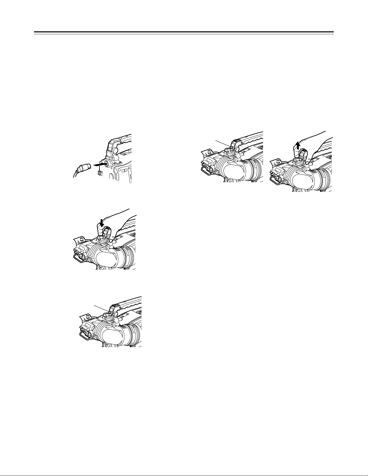
Attaching the viewfinder
1
Check that the camera’s POWER switch is at OFF.
2
Connect the plug to the viewfinder connecting
terminal.
<Note>
When connecting the plug to the viewfinder
connecting terminal, push the plug firmly into
place.
3
Push the viewfinder down.
4
Tighten the stopper screw firmly.
Detaching the viewfinder
1
Check that the camera’s POWER switch is at OFF.
2
Loosen the stopper screw, pull the viewfinder
straight up, and draw it out.
<Note>
Use both hands to draw the viewfinder out. It may
not be possible to remove the viewfinder smoothly
with one hand, which may cause damage to it.
3
Disconnect the plug from the viewfinder connecting
terminal.
Stopper screw
Stopper screw
Page 31

31
Adjusting the viewfinder (The viewfinder is an optional accessory.)
Adjusting the viewfinder position
1
Pull up the lever for securing the viewfinder in the
back/front and sideways directions to disengage
the lock.
2
Loosen the lever for securing the viewfinder in the
back/front and sideways directions.
3
Move the viewfinder in the back/front and sideways
directions, and adjust its position.
4
Tighten the lever for securing the viewfinder in the
back/front and sideways directions until it locks the
viewfinder in place.
Lever
Viewfinder
Page 32

32
Audio input preparation
1
Open the mic holder.
2
Attach the microphone, and tighten the locking
screw.
3
Connect the microphone’s connecting cable to the
MIC IN jack on the camera.
When attaching a microphone to
the viewfinder (optional accessory)
for use
The microphone of the AJ-MC700P mic kit (optional
accessory) can be attached to the viewfinder.
AJ-HVF27P
MIC IN jack
Mic holder
Locking
screw
4
Set the AUDIO IN switch or switches to “FRONT”
in accordance with the audio channel or channels
whose sound is to be recorded.
AUDIO IN switches
Page 33

33
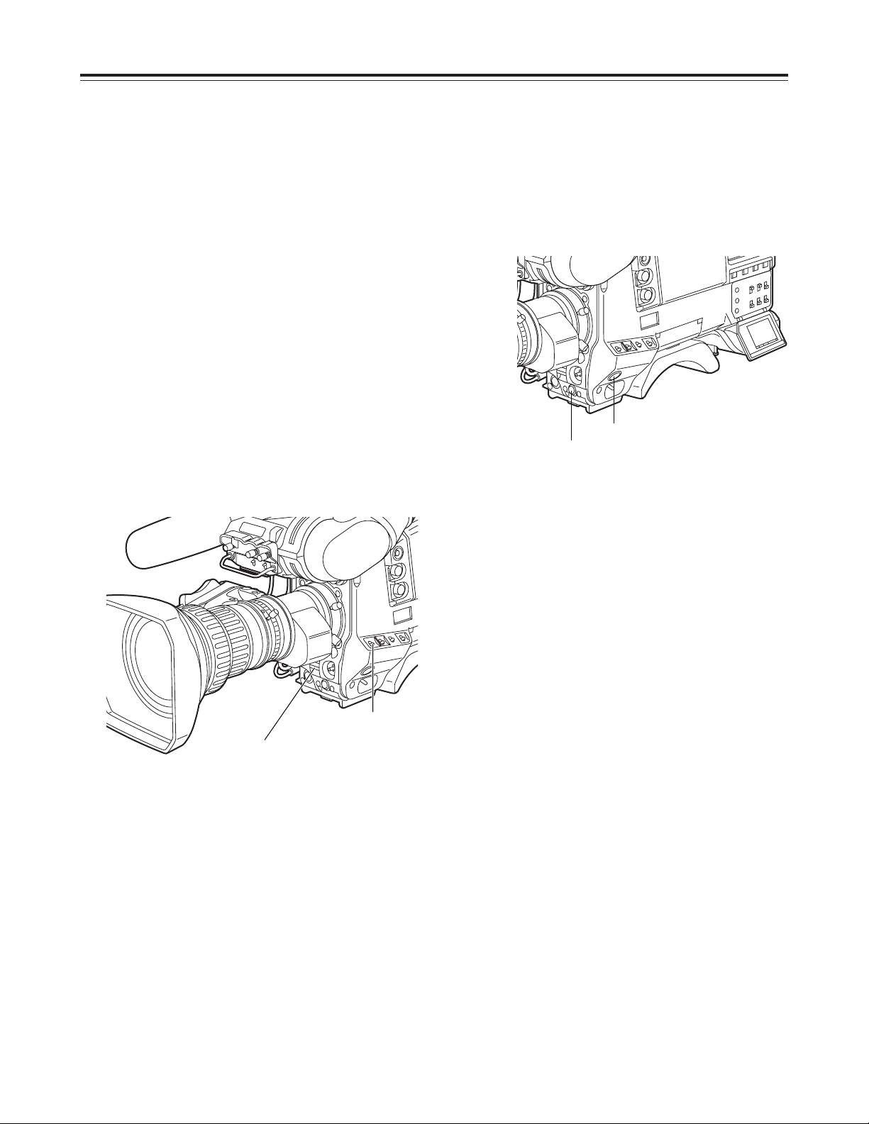
Audio input preparation
1
Remove the screws used to attach the mic holder.
2
Attach the mic holder to the main unit using the
screws provided with the AJ-MH700P mic holder.
Screws provided with mic holder
Locking screw
3
Attach the microphone to the mic holder, and
tighten the locking screw.
4
Connect the microphone’s connecting cable to the
MIC IN jack on the camera.
5
Set the AUDIO IN switch or switches to “FRONT”
in accordance with the audio channel or channels
whose sound is to be recorded.
Attaching the AJ-MH700P mic holder (optional
accessory)
When attaching a microphone to
the main unit for use
MIC IN jack
AUDIO IN switches
Page 34

34
Audio input preparation
1
Connect the microphone’s connecting cable to the
MIC IN jack on the camera.
2
Set the AUDIO IN switch or switches to “FRONT”
in accordance with the audio channel or channels
whose sound is to be recorded.
<Note>
When extending the microphone’s connecting cable,
use a cable which supports the phantom power supply
system.
<Note>
When the LINE/MIC/+48V selector switch is set to
“+48V,” the phantom power supply system is
supported.
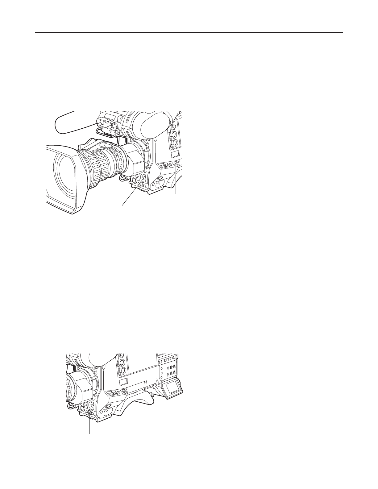
When connecting a microphone to
the MIC IN jack
1
Connect the microphone’s connecting cable to the
AUDIO IN connector on the camera.
Two microphones can be connected to the CH1
and CH2 connectors.
2
Set the AUDIO IN switch or switches for the
channel or channels to which the microphone or
microphones have been connected to “REAR.”
When connecting a microphone to
the AUDIO IN connector
MIC IN jack
AUDIO IN
connectors
AUDIO IN switches
AUDIO IN switches
Page 35

35
Audio input preparation
1
Attach the WX-RJ700 wireless receiver to the WXZJ770 camera attachment.
2
Align the grooves in the camera attachment with
the pins on the battery case, etc. to attach the
wireless receiver.
3
Connect the AUDIO IN connectors on the camera
with the wireless receiver using the XLR cable.
4
Set the AUDIO IN switch or switches for the
channel or channels to which the XLR cable has
been connected to “REAR.”
5
Set the LINE/MIC/+48V selector switch on the rear
panel to “MIC.”
3
Set the LINE/MIC/+48V selector switch on the rear
panel to “LINE.”
When detaching the wireless receiver, push up
the lever on the bottom panel of the camera
attachment to disengage it.
<Note>
For details on the operations and other aspects of the
WX-RJ700 wireless receiver, refer to the operating
instructions which accompany the receiver.
Attach the WX-RJ700 wireless receiver when
Panasonic’s wireless system is to be used.
When using a wireless microphone
WX-RJ700 wireless
receiver
WX-ZJ770 camera
attachment
Audio output connectors
AUDIO IN
connectors
AUDIO IN
switches
XLR cable
1
Connect the AUDIO IN connectors on the camera
with the audio component using the XLR cable.
2
Set the AUDIO IN switch or switches for the
channel or channels to which the microphone or
microphones have been connected to “REAR.”
When connecting audio components
AUDIO IN
connectors
AUDIO IN switches
LINE/MIC/+48V
selector switch
Page 36

36
Mounting the unit on a tripod
1
Attach the tripod attachment to the tripod.
<Note>
Select the attachment holes that best support the
center of gravity of the unit and tripod attachment.
Check that the diameters of the selected holes
match the diameters of the pan head.
2
Attach the camera to the tripod attachment.
Slide the camera toward the front along the
grooves until it clicks into place.
Use the tripod attachment available as an optional
accessory for mounting the unit onto a tripod.
Pan head
Tripod attachment
Red lever
Tripod attachment
Detaching the unit from the tripod attachment
While pressing the red lever, move the black lever in
the direction of the arrow, slide the unit toward the
rear, and detach it.
Black lever
<Note>
If the pins in the tripod attachment fail to return to
their original positions after the camera has been
detached, press the red lever again and at the same
time move the black lever in the direction of the
arrow: this will return the pins to their original
positions.
Bear in mind that the camera cannot be attached
while the pins are left in the center.
Page 37

37
Attaching the shoulder strap
1
Attach the shoulder strap to the shoulder strap
mounting hooks, and adjust the length of the strap.
<Note>
Check that the shoulder strap is securely fastened.
Shoulder strap
The clip opens
when it is
pressed here.
The clip opens when it
is pressed here.
To detach the shoulder strap, open the clips on the
mounting parts and detach.
Adjusting the shoulder pad position
1
Loosen the two screws.
2
Slide the shoulder pad either backward or forward,
and find the optimum position.
3
Tighten the screws to secure the shoulder pad.
The shoulder pad can be slid up to 15 mm either
backward or forward from the center position (factory
setting).
Adjust the pad’s position to operate the unit with the
optimum ease.
Shoulder pad
Screws
Bottom section
2
1•3
<Note>
This mounting hook is for attaching the tape measure
that is used to measure the subject distance.
It is not to be used for the shoulder strap.
Page 38

38
AJ-EC3
AJ-
65
∫
1
Connecting the extension control unit
Dedicated cable
ECU connector
By connecting the AJ-EC3 extension control unit
(optional accessory), some of the functions can be
operated by remote control.
When the AJ-EC3 is connected and the POWER
switches on the unit and AJ-EC3 are set to ON, the
unit is automatically set to the remote control mode.
<Notes>
OBefore connecting or disconnecting the dedicated
cable, be absolutely sure to set the POWER
switches on the unit and AJ-EC3 to OFF.
OWhen “OFF” has been selected as the ECU DATA
SAVE setting on the CAMERA SW MODE screen
of FILM (CAM) MAIN MENU 2, all the adjustments
and settings made using the AJ-EC3 will be cleared
when the unit’s power switch is set to OFF. Neither
is it possible to save these adjustments and
settings on a setup card.
However, the menu item settings can be saved on
a setup card.
When the AJ-EC3 is connected again, its settings
will be restored.
OWhen “ON” has been selected as the ECU DATA
SAVE setting on the CAMERA SW MODE screen
of FILM (CAM) MAIN MENU 2, all the adjustments
and settings made using the AJ-EC3 will not be
cleared even when the unit’s power switch is set to
OFF.
Attaching the rain cover
Tighten the cord.
Close using the fastener.
Close using the fastener.
Example showing use of the SHANRC700 rain cover
Page 39

39
TALLY / REC
BATT
VTR
SAVE
1
423
Viewfinder lamp displays
1 TALLY/REC (recording) lamp
This lights up (red) during recording. It flashes
when a problem has occurred.
For details, refer to the section on the “Warning
system” (pages 122, 123).
2 BATT (battery) lamp
This starts flashing when the battery voltage has
dropped to the level where the battery will no longer
be usable in several minutes’ time, and it lights
when the battery is no longer usable. To prevent
operation from being interrupted, replace the
battery before the battery has discharged
completely.
For details, refer to the section on the “Warning
system” (pages 122, 123).
3 (abnormal operating status warning) lamp
This lights when the unit is set to an abnormal
operating status for any of the items set to “ON” on
the “!LED” screen of the setting menu.
For details on selecting the items targeted for the
lamp display, refer to the section on “Setting the
lamp displays” (next page).
4 VTR SAVE (VTR power-saving) lamp
This lights when the VTR SAVE/STBY switch is set
to SAVE. It goes off during recording.
<Note>
In the rec pause mode, the SAVE mode is
established automatically, and the lamp lights after
the time set for the pause timer (temporary stop
time) has elapsed.
After two minutes in the play pause mode, the
SAVE mode is established automatically, and the
lamp lights.
Viewfinder pictured here is the AJ-HVF27P
(For details concerning the viewfinder, refer to
the operating intructions of the viewfinder.)
Page 40

40
Viewfinder lamp displays
Setting item
Description of setting
GAIN (0 dB) Lamp display appears when the gain is
set to a value other than “0 dB.”
GAIN (–3 dB) Lamp display appears when the gain is
set to a value other than “–3 dB.”
SHUTTER Lamp display appears when the
SHUTTER switch is at ON.
WHITE PRESET Lamp display appears when “PRST”
applies to the channel in the white
balance memory.
EXTENDER Lamp display appears when the lens
extender is used.
FILTER Lamp display appears when the filter is
set to a value other than “3200 K.”
BLACK STR Lamp display appears when the black
stretch is at ON.
DAY LIGHT
(FILM MENU)
Lamp display appears when the white
balance presetting is DAY LIGHT.
D5600K
(CAM MENU)
Lamp display appears when the white
balance presetting is 5600 K.
Setting the lamp displays
Select the items targeted for the lamp display on
the “!LED” screen of the FILM (CAM) MAIN MENU 2
screen. (Under the factory settings, the “!LED” screen
is not displayed.)
To perform operations on the “!LED” screen, either
switch the unit to the engineer mode menu or select
the “!LED” screen on the FILM (CAM) USER MENU
SELECT 2 screen under the FILM (CAM) MAIN
MENU 4 screen.
<Note>
For details on selecting the engineer mode menu and
display screens, refer to “Menu operations” (pages 84
to 86).
1
Perform the menu operations (pages 84 to 86) to
open the “!LED” screen.
2
Turn the JOG dial button to move the arrow
(cursor) to the desired item.
4
Repeat steps 2 and 3 to set ON or OFF for the
other items.
3
For the selected item, press the JOG dial button,
and set whether or not the item is to be displayed
on the viewfinder screen.
Turn the JOG dial button, select display (ON) or no
display (OFF) and press the JOG dial button to
enter the selection.
5
Press the MENU button to exit the menu
operations.
The setting menu is cleared, and the displays
showing the unit’s current statuses appear at the
top and bottom of the viewfinder screen.
n
< !LED >
GAIN(0dB) :ON
GAIN(–3dB) :OFF
SHUTTER :ON
WHITE PRESET :OFF
EXTENDER :ON
FILTER :OFF
BLACK STR :OFF
DAY LIGHT :OFF
MATRIX :OFF
COLOR CORRECTION :OFF
FRAME RATE :ON
MATRIX Lamp display appears when the matrix is
at ON.
COLOR
CORRECTION
Lamp display appears when the color
correction is at ON.
FRAME RATE Lamp display appears when the frame
rate has been set to 11 fps or below.
Page 41

41
Viewfinder screen status displays
In addition to the pictures shot, the unit’s settings and
messages indicating its operating statuses are
displayed on the viewfinder screen. The center
marker and safety zone markers also appear.
The items which have been set to ON by the switches
relating to the viewfinder displays or the VF DISPLAY
screen of the setting menu are displayed at the top
and bottom of the screen.
When settings have been changed or adjustments
have been made, messages advising the user of what
has been set, what progress has been made in the
adjustments and what the adjustment results are can
be displayed for about 3 seconds.
$ Display items and where they are displayed
1 Extender display
2 Shutter speed/mode display
3 Remaining tape display
4 Battery voltage display
5 Filter display
6 White balance memory display
7 Gain display
8 Audio level display
9 Aperture display
: Camera warning/information display
; Safety zone markers
< Center marker
= Super iris ON display
> Zoom position display
? TCG display
@ Master gain setting display
A Color temperature display PRE/A/B
B Battery type
C Total tape length
D Preset color temperature display
E VTR warning/information display
F Interval recording mode display (flashing)
G AUDIO CH1/CH2 input display
H Frame rate information display
I lamp information display
J Frame frequency information display
K Operation mode display
24
EX2
1/250 S 10min 14.6V
/46 BP402
1B A 12dB
TCG 00:00:00:00
F5.6 Z99
iREC
!D.L.
5
;
;
@
I
D
59.9
F
J
K
?
:
1
;
F
;
B
E
<
6 7 G8 9 >
H 2 = 3 CA 4
Page 42

42
Viewfinder screen status displays
1 Extender display
This appears when the lens extender is being used.
2 Shutter speed/mode display
This indicates the shutter speed or shutter mode
setting.
The unit in which the shutter speed is displayed can
be set on the VF DISPLAY screen of FILM (CAM)
MAIN MENU 2.
OOFF (no display):
The shutter is not used.
O1/100, 1/120, 1/250 1/500, 1/1000, 1/2000
(180d, 172.8d, 144d, 120d, 90d, 45d):
Shutter speeds in the fixed mode
O3.0d to 350.0d/0.8% to 97.2% (SYNCHRO
SCAN):
Selection of synchro scan mode
In the synchro scan mode, “Y” appears
immediately in front of the number displayed.
3 Remaining tape display
During recording, this shows the remaining tape (in
minutes) in the VTR. When less than two minutes
of tape remain, the figure starts flashing.
4 Battery voltage display
This indicates the battery voltage (V) during
operation. The voltage is displayed as a
percentage when a digital battery is used.
5 Filter display
This indicates the type of filter selected.
6 White balance memory display
This indicates the automatic adjustment memory
selected for the white balance.
A: The WHITE BAL switch has been set to “A.”
B: The WHITE BAL switch has been set to “B.”
P: The WHITE BAL switch has been set to “PRST.”
7 Gain display
This indicates the gain (dB) of the video amplifier
which was set using the GAIN switch.
8 Audio level display
This indicates the audio level (which can be
displayed separately for audio CH1 and CH2).
During sine wave input, it roughly corresponds with
the VTR’s level meter as shown below.
9 Aperture display
This indicates the approximate aperture setting (F
number).
<Note>
This appears when a lens with an aperture display
function is being used.
: Camera warning/information display
The black balance, white balance, auto knee
function, super iris, super gain and other alarm
displays and warnings appear here.
; Safety zone markers
These indicate the 80% or 90% (factory setting)
range of the surface area of the viewfinder screen.
The display range proportion is set on the VF
DISPLAY screen of the setting menu.
For details, refer to “Setting the marker displays”
(page 46).
< Center marker
This indicates the center of the viewfinder screen.
The display is set ON or OFF on the VF DISPLAY
screen of the setting menu.
= Super iris ON display
“S” appears when the super iris is ON.
> Zoom position display
The distance from the WIDE end to TEL end of the
zoom lens is indicated here as a number from 0 to
99.
? TCG display
This indicates the time code generator value.
@ Master gain setting display
The GAIN L/M/H values currently set appear here
when the MODE CHECK button is pressed.
A Color temperature display PRE/A/B
This indicates the color temperature when AWB is
executed using white balance memory A or B.
Audio level display
VTR’s level meter
-40 -30 -25 -18/20 -15 -10 -5 0
+
Page 43

43
Viewfinder screen status displays
B Battery type
This indicates the type of battery selected.
C Total tape length
This indicates the total length of the cassette tape.
D Preset color temperature display
This indicates the preset white balance value.
E VTR warning/information display
Alarm displays such as SLACK, REC WARNING,
HUMID, SERVO and RF as well as other warnings
are indicated here.
F Interval recording mode display (flashing)
G AUDIO CH1/CH2 input display
The input signals to be recorded in audio channels
1 and 2 are indicated here.
H Frame rate information display
This indicates the frame rate which has been set.
I
lamp information display
This indicates the information when the lamp
has lighted.
J Frame frequency information display
This indicates the frame frequency (59.9 Hz or
60.00 Hz) which has been set.
K Operation mode display
This indicates the unit’s operation mode (F: FILM or
V: VIDEO) which has been set.
Selecting the display items
The items to be displayed on the viewfinder screen
can each be set to ON or OFF on the “VF
INDICATOR” screen of the FILM (CAM) MAIN MENU
2 or on the “VTR VF INDICATOR” screen of the VTR
MENU.
Selectable items
On the “VF INDICATOR” screen of FILM (CAM)
MENU
OExtender display (EXTENDER)
OShutter speed/mode display (SHUTTER)
OFilter display (FILTER)
OWhite balance memory display (WHITE)
OGain display (GAIN)
OAperture value and super iris ON display (IRIS)
OCamera ID display (CAMERA ID)
OZoom position display (ZOOM LVL)
OColor temperature display (COLOR TEMP)
OFrame rate display (FRAME RATE)
OGamma curve display (VERSION ID)
<Note>
The camera ID appears when color bar signals are
to be recorded in accordance with the
OUTPUT/AUTO KNEE switch setting.
For details, refer to “Setting the camera ID” (page
47).
n
< VF INDICATOR >
EXTENDER :ON
SHUTTER :ON
FILTER :ON
WHITE :ON
GAIN :ON
IRIS :S+IRIS
CAMERA ID :ON
ZOOM LVL :OFF
COLOR TEMP :ON
FRAME RATE :ON
VERSION ID :ON
Page 44

44
Viewfinder screen status displays
Selecting the display items
1
Perform the menu operations (pages 84 to 86) to
open the “VF INDICATOR” screen.
2
Turn the JOG dial button to move the arrow
(cursor) to the desired item.
4
Repeat steps 2 and 3 to set ON or OFF for other
items.
3
For the selected item, press the JOG dial button,
and set whether or not the item is to be displayed
on the viewfinder screen.
Turn the JOG dial button to select display (ON) or
no display (OFF), and press the JOG dial button to
enter the selection.
5
Press the MENU button to exit the menu
operations.
The setting menu is cleared, and the displays
showing the unit’s current statuses appear at the
top and bottom of the viewfinder screen.
n
< VTR VF INDICATOR >
TAPE(IND) :ON
BATTERY(IND) :ON
LEVEL METER(IND) :CH1
AUDIO IN(IND) :OFF
TC(IND) :OFF
VTR WARNING(IND) :NORMAL
SAVE LED :SAVE
On the “VTR VF INDICATOR” screen of VTR MENU
ORemaining tape display (TAPE)
ORemaining battery charge display (BATTERY)
OLevel meter display (LEVEL METER)
OTime code display (TC)
OVTR warning display (VTR WARNING)
OSAVE lamp display (SAVE LED)
n
< VTR VF INDICATOR >
TAPE(IND) :ON
BATTERY(IND) :ON
LEVEL METER(IND) :CH1
AUDIO IN(IND) :OFF
TC(IND) :OFF
VTR WARNING(IND) :NORMAL
SAVE LED :SAVE
n
< VF INDICATOR >
EXTENDER :ON
SHUTTER :ON
FILTER :ON
WHITE :ON
GAIN :ON
IRIS :S+IRIS
CAMERA ID :ON
ZOOM LVL :OFF
COLOR TEMP :ON
FRAME RATE :ON
VERSION ID :ON
Page 45

45
Viewfinder screen status displays
Display modes and setting
change messages
The display of messages advising the user of what
changes have been made to the settings and what the
adjustment results are can be turned off for some or
all of the items displayed.
<Note>
The message displays also depend on the status of
other menu settings. For instance, even when “1 (no
display)” is set as the filter selection, the filter
selection will be displayed when FILTER is set to “ON”
on the VF INDICATOR screen.
±±
: Message is to be displayed.
tt
: Message is not to be
displayed.
Setting change/adjustment result messages and display modes
Situation in which message is displayed Message
Display mode
setting
123
tt tt ±±
When the filter selection has been changed Filter: n (n=1, 2, 3, 4), m (m=A, B, C, D)
tt tt ±±
When the gain setting has been changed GAIN: n dB
(n= –6, –3, 0, 3, 6, 9, 12, 18, 24, 30)
tt tt ±±
When the WHITE BAL switch setting has been
changed
WHITE: n (n=ACH, BCH, PRESET)
tt ±± ±±
When the OUTPUT/AUTO KNEE switch has
been set to AUTO KNEE or OFF
<Note>
This display is shown for about 3 seconds
immediately after the unit’s power has been
switched on.
AUTO KNEE: ON (or OFF)
tt ±± ±±
When the shutter speed/mode setting has been
changed
SS: 1/100 (or 1/120, 1/250, 1/500, 1/1000, 1/2000,
S.SCAN, 3.0d to 350.0d, 0.8% to 97.2%)
tt ±± ±±
When the white balance (AWB) has been
adjusted
Example) AWB: OK
For details, refer to “Adjusting the white balance”
(pages 50 to 53).
tt ±± ±±
When the black balance (ABB) has been
adjusted
Example) ABB: OK
For details, refer to “Adjusting the black balance”
(page 54).
Page 46

46
Viewfinder screen status displays
Switching the display mode
The display mode settings are switched on the VF
DISPLAY screen.
1
Perform the menu operations (pages 84 to 86) to
open the “VF DISPLAY” screen of FILM (CAM)
MAIN MENU 2.
2
Turn the JOG dial button to move the arrow
(cursor) to the “DISP MODE” item.
3
Press the JOG dial button, and set the desired
display mode.
Turn the JOG dial button to select the display
contents, and press the JOG dial button to enter
the selection.
4
Press the MENU button to exit the menu
operations.
The setting menu is cleared, and the displays
showing the unit’s current statuses appear at the
top and bottom of the viewfinder screen.
n
< VF DISPLAY >
DISP CONDITION :NORMAL
DISP MODE :3
VF OUT :Y
VF DTL :4
ZEBRA1 DETECT :080%
ZEBRA2 DETECT :085%
ZEBRA2 :SPOT
LOW LIGHT LVL :45%
SYNCHRO SCAN DISP.:deg
ECU MENU DISP. :ON
Setting the marker displays
The center marker and safety zone marker displays
are set on the VF MARKER screen.
1
Perform the menu operations (pages 84 to 86) to
open the “VF MARKER” screen of FILM (CAM)
MAIN MENU 2.
2
Perform the same operations as for the “VF
DISPLAY” screen to set each item.
n
< VF MARKER >
SAFETY ZONE :3
CENTER MARK :ON
FRAME SIG :4:3
MARK :OFF
LVL :15
Page 47

47
Viewfinder screen status displays
Setting the camera ID
The camera ID is set on the CAMERA ID screen.
Up to ten alphanumerics, symbols and spaces can be
used.
<Note>
The camera ID is not displayed while the setting menu
is displayed even if color bar signals are output.
<Note>
The camera ID is recorded at the same time as the
color bar signals if “CAMERA ID” on the VF
INDICATOR screen has been set to “ON.”
1
Perform the menu operations (pages 84 to 86) to
open the “CAMERA ID” screen of FILM (CAM)
MAIN MENU 2.
4
Turn the JOG dial button until the character to be
set appears. When the button is turned, the
character displayed is switched in the following
sequence:
Space: )
7
letters: A—Z
7
numbers: 0—9
7
symbols: ’, >, <, /, –
6
Turn the JOG dial button to move the arrow
(cursor) to the next position (right), and repeat
steps 4 and 5to set the characters.
5
Press the JOG dial button to enter the character.
9
Press the MENU button to exit the menu
operations.
The setting menu is cleared, and the displays
showing the unit’s current statuses appear at the
top and bottom of the viewfinder screen.
n
< CAMERA ID >
ID 1:
2222222222
ID 2:
2222222222
ID 3:
2222222222
2
Turn the JOG dial button to move the arrow
(cursor) to the “ID 1: to 3:” item.
3
When the JOG dial button is pressed, the arrow
(cursor) moves to the ID input area, and the input
mode is established.
< CAMERA ID >
n
ID 1:
2222222222
ID 2:
2222222222
ID 3:
2222222222
< CAMERA ID >
m
ID 1:
2222222222
ID 2:
2222222222
ID 3:
2222222222
7
When the characters have been input, turn the
JOG dial button to move the arrow (cursor) to the
“:” position.
8
When the JOG dial button is pressed, the arrow
(cursor) returns to the ID 1:, ID 2: or ID 3: item.
< CAMERA ID >
m
ID 1:
2222222222
ID 2:
2222222222
ID 3:
2222222222
Page 48

48
CH1 CH2
20
0
EMPHASIS
40
-dB
10
30
E
BATT
F
TAPE
RF
SERVO
HUMID SLACK
DF
SLAVE TCG HOLD
h min s frm
Screen displays
Displays relating to errors and
warnings
For details, refer to “Warning system” (pages 122 and
123).
Remaining tape display
The remaining tape time is displayed using 7 segments.
The remaining tape time indicated by each segment is set
to 3 minutes or 5 minutes using TAPE REMAIN/ $ on the
VTR MENU “BATTERY/TAPE” screen. Each time the
number of minutes set for the segments elapses, one
segment is cleared. (See page 114)
Remaining battery charge display
If a battery with a digital display (% display) is used, all 7
segments up to the “F” position light when the 70% or
more of the battery charge remains.
When there is less than 70% of the battery charge
remaining, the segments go out one by one in sequence
every time the remaining charge drops by 10%.
Audio channel level meter
CH1 CH2
20
0
EMPHASIS
40
-dB
10
30
E
BATT
F
TAPE
RF
SERVO
HUMID SLACK
DF
SLAVE TCG HOLD
h min s frm
Error code display
Warning displays
RF : Clogged video head
SERVO: Servo disturbance
HUMID : Formation of condensation on the head drum
SLACK:Problem in tape take-up
Displays relating to time codes
Time code-related switch settings and display
items
CH1 CH2
20
0
EMPHASIS
40
-dB
10
30
E
BATT
F
TAPE
RF
SERVO
HUMID SLACK
DF
SLAVE TCG HOLD
h min s frm
Time counter display
This displays the time code, CTL, user’s bit and actual
time. For the correlation between the items displayed and
the switches, refer to the next section.
These displays light for the time code, CTL and actual
time
DF :Drop frame mode
SLAVE : External locking of the time code
HOLD : Time code generator in the hold mode (when the
HOLD button has been pressed)
TCG switch
position
DISPLAY switch
position
Display item
SET
TC or CTL Time code
F-RUN or R-RUN
UB User’s bit
CTL CTL
TC Time code
UB User’s bit
<Note>
If the HOLD button is pressed while the DISPLAY
switch is set to UB, “HOLD” on the counter display will
flash for as long as the switch is held down, and the
VITC user’s bit information recorded in the video AUX
area will appear on the counter display.
Remaining battery charge and
audio channel level and
remaining tape displays
Page 49

49
Adjusting the date and time
Adjustments and setup using
the setting menus
1
Perform the menu operations (pages 84 to 86),
and display the “TIME/DATE” screen of VTR MAIN
MENU.
2
Turn the JOG dial button to select the item to be
changed, and press the JOG dial button.
3
Turn the JOG dial button to change the setting,
and press the JOG dial button to enter the setting.
4
When the settings are completed, press the JOG
dial button to select $ TIME/DATE SET, and press
the JOG dial button.
5
Press the MENU button to exit the menu
operations.
The setting menu is cleared, and the displays
showing the unit’s current statuses appear at the
top and bottom of the viewfinder screen.
<Note>
The seconds cannot be set. The time always
advances from 0 seconds.
n
< TIME/DATE >
YEAR :02
MONTH :01
DAY :01
HOUR :00
MINUTE :00
$
TIME/DATE SET
< TIME/DATE >
YEAR :02
MONTH :01
DAY :01
HOUR :00
n
MINUTE :00
$
TIME/DATE SET
< TIME/DATE >
YEAR :02
MONTH :01
DAY :01
HOUR :00
MINUTE :00
n
$
TIME/DATE SET
Page 50

50
Adjusting the white balance and black balance
Adjusting the white balance
1
Set the switches as shown in the figure.
FILTER control
WHITE BAL: A or B
OUTPUT: CAM
GAIN: Normally 0 dB
Set to a more suitable gain level if it is
too dark.
When the GAIN and WHITE BAL switch settings
are changed, messages advising the user of the
set positions appear on the setting change
message display of the viewfinder screen.
(However, this happens only when “3” has been
set as the display mode.)
2
Select the FILTER control setting in accordance
with the lighting conditions.
OFor examples of the FILTER control settings,
refer to the description of the FILTER control
(page 14) in the “Shooting (recording)/playback
function section.”
When the FILTER control setting is changed, a
message advising the user of the set positions
appears on the setting change message display
of the viewfinder screen. (However, this
happens only when “3” has been set as the
display mode.)
A better picture can be achieved by adjusting the
white balance and black balance in the following
sequence: AWB (white balance adjustment) 5 ABB
(black balance adjustment) 5 AWB.
There is usually no need to re-adjust the black
balance even when the power has been turned off
and back on.
The white balance must always be re-adjusted when
the lighting conditions have changed.
If the display mode is set to “2” or “3,” messages
advising the user of what progress has been made in
the adjustments and what the adjustment results are
appear on the viewfinder screen when the black
balance or white balance adjustment is commenced.
Set the display mode to “1” if these messages are not
to be displayed.
OFor details on the display mode settings, refer to
“Display modes and setting change messages”
(page 45).
<Notes>
OABB must be performed when the MASTER GAIN
levels have been changed on the LOW SETTING,
MID SETTING and HIGH SETTING screens of the
FILM (CAM) MAIN MENU 1, when the super gain
setting has been changed using the USER button,
and when the GAMMA (ON/OFF) has been
switched on the CAMERA SETTING screen.
OWith artificial lighting—particularly fluorescent lights
and mercury lamps—the luminance may appear to
be constant but the intensity of the R, G and B
colors will change in synchronization with the power
line frequency. Especially in regions with a 50 Hz
power line frequency, mutual interference arises
between the vertical sync frequency (approx. 60
Hz) of this unit and lighting frequency (50 Hz). As a
result, the hue tends to change with the passage of
time or flickering occurs, making it impossible to
achieve a proper white balance.
It is recommended that the white balance be
achieved using the settings shown in the table
below.
Power line frequency
Shutter speed
50 Hz
1/100
60 Hz
OFF
Page 51

51
Adjusting the white balance and black balance
Adjusting the white balance
3
Erect a white pattern at a place with the same
conditions as the source of light illuminating the
subject, zoom in, and shoot the white of the pattern
on the screen.
A white object (such as a white cloth or white wall)
near the subject may be used as a substitute for
the white pattern.
The size of the white object required is shown in
the figure below.
4
Adjust the lens aperture.
5
Set the AUTO W/B BAL switch to AWB, and then
release it.
The switch returns to the center, and the white
balance is automatically adjusted.
At least one-fourth of
the screen width
At least one-fourth of
the screen height
<Notes>
OTake care to keep high-brightness spots off the screen.
OShoot white objects in the center of the screen.
6
While the adjustment is in progress, the following
message appears on the viewfinder screen (but
only when “2” or “3” has been set as the display
mode).
AWB ACTIVE
AUTO W/B BAL switch
Message appearing while the adjustment is in
progress
7
Adjustment is completed in several seconds. (A
message similar to the one shown in the figure
now appears.)
The adjustment value is automatically saved in the
memory (A or B) which was set in step 1.
AWB A OK 3.2K
Message appearing upon completion of the
adjustment
8
A message such as the following appears if the
color temperature of the subject is lower than 2300
K or higher than 5600 K.
The downward pointing arrow indicates that the
color temperature is lower than the display
temperature; conversely, the upward pointing
arrow indicates that the it is higher than the display
temperature.
<Note>
When a zoom lens with an automatic aperture
function is used, aperture hunting may occur. Adjust
the aperture’s gain control (marked as IG, IS, S, etc.)
provided with the lens.
For details, refer to the operating instructions which
accompany the lens.
Hunting:
The auto iris response is repeated, causing the brightness levels
of the image to become inconsistant.
AWB A OK 2.3K
m
When the color temperature is lower than 2300 K
AWB A OK 5.6K
m
When the color temperature is higher than 5600 K
<Note>
When the AUTO W/B BAL switch is pressed again to
the AWB side when the white balance is being
adjusted automatically (AWB ACTIVE), the
adjustment operation will stop.
The adjusted value in this case is the value before
automatic adjustment was performed.
Page 52

52
Adjusting the white balance and black balance
Adjusting the white balance
When the white balance cannot
automatically be adjusted
An error message appears on the viewfinder screen
(when “2” or “3” has been set as the display mode).
When there is no time to adjust the white
balance
Set the WHITE BAL switch to PRST. The white
balance for the filter is achieved in accordance with
the setting position of the FILTER control (outer).
White balance memories
There are two sets of white balance memories, A and
B.
When the FILTER INH setting on the CAMERA SW
MODE screen of FILM (CAM) MAIN MENU 4 is ON
(default setting), the number of memories for set A
and set B is limited to one each. In this case, the
memory contents are not coupled with the filter.
When FILTER INH is set to OFF, the adjustment
values for each filter can be automatically saved in the
memories corresponding to the WHITE BAL switch
settings (A or B). This unit contains four filters so that
a total of 8 (4a2) adjustment values are saved.
When any of the error messages listed above is
displayed, take the recommended action, and try
adjusting the white balance again.
If the error message persists even after repeated
attempts, consult your dealer.
<Notes>
On rare occasions, AWB cannot be adjusted and a
NG display appears. In a case like this, adjust AWB
again.
Messages relating to white balance adjustment
Error
message
Meaning Recommended action
Select a suitable filter.
COLOR TEMP.
HIGH
Color temperature is too
high.
Select a suitable filter.COLOR TEMP.
LOW
Color temperature is too
low.
Increase the amount of
light or increase the
gain.
LOW LIGHT There is not enough
light.
Reduce the amount of
light or reduce the gain.
LEVEL OVER There is too much light.
Check the filter selector
control.
CHECK
FILTER
The setting position of
the filter selector control
is not correct.
If flickering is to blame,
install the shutter, and
stabilize the shooting
conditions.
UNSTABLE
CONDITION
The shooting conditions
are unstable (shooting
under fluorescent light,
unstable camera
posture, etc.).
White balance search area
It is possible to set the white balance search area to
either 90%, 50% or 25% by changing the AWB AREA
setting on the OPTION screen of the FILM (CAM)
MAIN MENU 4.
90%
50%
25%
When using the unit in film mode
When there is a large difference between the CC filter
setting and the color temperature of the subject, the
dynamic range of the video signals may not be utilized
to full potential.
We recommend that the CC filter setting selected is
one that is close to the color temperature of the
subject.
Page 53

53
Adjusting the white balance and black balance
Adjusting the white balance
When FILTER INH is set to ON
When AWB is adjusted, the color temperature and
filter number applying at the time are displayed.
If the filter is then turned, the color temperature and
filter number are displayed.
The white balance is almost fully adjusted if the
subject is illuminated at a color temperature
approaching the one displayed.
AWB is adjusted using subject filter (B) with a
lighting color temperature of 3200 K.
(Example of display)
AWB A OK 3.2K
7
The filter is changed to filter (C)
7
The filter (B) is restored.
7
“4.3 K” is displayed.
(1): This indicates that AWB was adjusted using
the filter.
CC:C
4.3K
7
“3.2 K” is displayed, and the status when AWB was
first adjusted is indicated.
3.2K
If the color temperature of the subject in this state
is near 4.3 K, the white balance is right and so the
camera can be used.
7
Page 54

54
Adjusting the white balance and black balance
Adjusting the black balance
1
Set the switches as shown in the figure.
OUTPUT: CAM
AUTO W/B switch
2
Set the AUTO W/B BAL switch to the ABB position,
and then release it.
The switch returns to the center, and the
adjustment is performed.
The black balance needs to be adjusted in the
following cases:
OWhen the unit is used for the first time
OWhen the unit is used after it has not been used for
a prolonged period of time
OWhen the unit is used in an ambient temperature
which has fluctuated significantly
OWhen the value selected for the gain switch has
been changed
OWhen the super gain setting has been performed
using the USER button
OWhen the gamma ON/OFF setting has been
changed
OWhen the frame rate setting has been changed
3
While the adjustment is in progress, the following
message appears on the viewfinder screen (but
only when “2” or “3” has been set as the display
mode).
<Note>
While the adjustment is in progress, the lens
aperture is automatically set to CLOSE.
ABB ACTIVE
Message appearing while the adjustment is in
progress
4
Adjustment is completed in several seconds. (A
message similar to the one shown in the figure
now appears.)
The adjustment value is automatically saved in the
memory.
ABB OK
Message appearing upon completion of the
adjustment
<Notes>
OCheck that the lens connector has been connected
and that the lens aperture is set to CLOSE.
OWhile the black balance is being adjusted, the
aperture is automatically set to the light-shielding
status.
OWhile the black balance is being adjusted, the gain
selector circuit is switched automatically.
Flicker or noise may appear on the viewfinder
screen, but this is not indicative of malfunctioning.
OIf black shading is not satisfactory even with ABB
OK, open the BLACK SHADING screen of FILM
(CAM) MAIN MENU 4, and adjust the black
shading. (Refer to page 108.)
OWhen the super gain has been set to ON, the black
balance is executed at the preset position in the
white balance memory.
OWhen the AUTO W/B BAL switch is pressed again
to the ABB side when the black balance is being
adjusted automatically (ABB ACTIVE), the
adjustment operation will stop.
The adjusted value in this case is the value before
automatic adjustment was performed.
Page 55

55
Setting the electronic shutter
Shutter modes
<Notes>
ONo matter in which mode the electronic shutter is
used, the higher the shutter speed, the lower the
camera’s sensitivity.
OWhen the aperture is in the automatic mode, it will
increasingly open and the depth of focus will
become shallower as the shutter speed is
increased.
Available shutter modes and shutter speeds
Mode
Shutter speed Application
For shooting fast-moving
subjects clearly
Fixed
POSITION 1 to 6
For shooting in such a way
that the horizontal striping is
minimized on the monitor
screen
SYNCHRO
SCAN
Aperture angle: 3 to
350 degrees
(0.8% to 97.2% of the
frame rate)
Registering the shutter speed
The shutter speed is registered in the “SHUTTER
SELECT” screen of FILM (CAM) MAIN MENU 2.
1/100 , 1/120, 1/250, 1/500, 1/1000 and 1/2000 sec.
(or 180.0, 172.8, 144.0, 120.5, 90.0 and 45.0 deg)
1
Perform the menu operations (pages 84 to 86),
and display the “SHUTTER SELECT” screen.
4
Press the MENU button to exit the menu
operations.
The setting menu is cleared, and the displays
showing the unit’s current statuses appear at the
top and bottom of the viewfinder screen.
2
Turn the JOG dial button to move the arrow
(cursor) to the desired item.
3
Press the JOG dial button to set the shutter speed
to be changed.
Turn the JOG dial button to select ON or OFF, and
press the button to enter the setting.
It is possible to set a fixed speed within the range
of 90.0 to 225.0 degrees (in units of 0.5 deg.) in
SYNCHRO SCAN 2.
It is also possible to set 6 different shutter speeds
in POSITION 1 to 6, respectively.
n
< SHUTTER SELECT >
SYNCHRO SCAN 2 :180deg
POSITION 1 :1/100
POSITION 2 :1/120
POSITION 3 :1/250
POSITION 4 :1/500
POSITION 5 :1/1000
POSITION 6 :1/2000
Page 56

56
Setting the electronic shutter
Changing the shutter speed
and mode selection range
1
Perform the menu operations (pages 84 to 86),
and display the “SHUTTER SPEED” screen.
4
Press the MENU button to exit the menu
operations.
The setting menu is cleared, and the displays
showing the unit’s current statuses appear at the
top and bottom of the viewfinder screen.
<Notes>
OWhen operating the unit from the AJ-EC3 extension
control unit (optional accessory), the shutter speed
selected by the AJ-EC3 switch will take precedence
in determining the actual shutter speed even when
operations have been performed on the unit’s
SHUTTER SPEED screen.
OFor details on selecting the engineer mode and
display screens, refer to “Menu operations” (pages
84 to 86).
On the SHUTTER SPEED screen of FILM (CAM)
MAIN MENU 2, the setting range of the shutter speed
can be restricted to the required range and whether or
not to use the special operation mode (SYNCHRO
SCAN) can be selected.
2
Turn the JOG dial button to move the arrow
(cursor) to the desired item.
3
Press the JOG dial button to set the item to be
changed.
Turn the JOG dial button to select ON or OFF, and
press the button to enter the setting.
n
< SHUTTER SPEED >
SYNCHRO SCAN 1 :ON
SYNCHRO SCAN 2 :OFF
POSITION 1 :ON
POSITION 2 :ON
POSITION 3 :ON
POSITION 4 :ON
POSITION 5 :ON
POSITION 6 :ON
POSITION1 POSITION2
SYNCHRO SCAN 1SYNCHRO SCAN 2
POSITION3 POSITION4 POSITION5 POSITION6
Setting the shutter mode and
speed
1
Following the steps for “Switching the display
mode” (page 46), set DISP MODE to “2” or “3” on
the VF DISPLAY screen of FILM (CAM) MAIN
MENU 2.
SHUTTER switch
Example: “1/120,” “50.0%,” etc.
2
Press the SHUTTER switch from ON to SEL.
The current shutter setting appears on the setting
change message display area of the viewfinder
screen.
Fixed mode
3
Press the SHUTTER switch to the SEL position
again, and repeat this until the desired mode or
speed is displayed.
When all the modes and speeds are displayed, the
display will change in the sequence shown below.
When the required shutter speed and mode have
been assigned beforehand, only the assigned
speed or mode will be displayed.
OThe SHUTTER switch is used to set the shutter
speed and the shutter speed in the fixed mode.
OThe shutter speed in the SYNCHRO SCAN mode
can easily be changed using the SYNCHRO (“+”
and “–”) buttons.
OOn the SHUTTER SPEED screen of FILM (CAM)
MAIN MENU 2, the setting range of the shutter
speed can be restricted to the required range and
whether or not to use the special operation mode
(SYNCHRO SCAN) can be selected.
Page 57

57
Setting the electronic shutter
Switching the shutter speed
display
The unit enables the SYNCHRO SCAN mode to be
displayed on the viewfinder screen to be switched to
“1/¢¢¢ (sec.),” “¢¢¢%” or “¢¢¢d (angle)” on the
VF DISPLAY screen of FILM (CAM) MAIN MENU 2.
1
Perform the menu operations (pages 84 to 86),
and open the VF DISPLAY screen.
2
Turn the JOG dial button to move the arrow
(cursor) to the SYNCHRO SCAN DISP. item.
3
Press the JOG dial button to set the SYNCHRO
SCAN display mode.
Turn the JOG dial button, select the display, and
then press the JOG dial button to enter the
selection.
sec (seconds): 1/¢¢¢
%:¢¢¢%
deg (angle) : ¢¢¢d
e.g.
When the frame rate is set to 24 fps and exposure
time is set to half:
1/48 sec = 50% = 180 deg.
4
Press the MENU button to exit the menu
operations.
The setting menu is cleared, and the displays
showing the unit’s current statuses appear at the
top and bottom of the viewfinder screen.
n
< VF DISPLAY >
DISP CONDITION :NORMAL
DISP MODE :3
VF OUT :Y
VF DTL :4
ZEBRA1 DETECT :070%
ZEBRA2 DETECT :085%
ZEBRA2 :SPOT
LOW LIGHT LVL :45%
SYNCHRO SCAN DISP.:deg
ECU MENU DISP. :ON
< VF DISPLAY >
DISP CONDITION :NORMAL
DISP MODE :3
VF OUT :Y
VF DTL :4
ZEBRA1 DETECT :070%
ZEBRA2 DETECT :085%
ZEBRA2 :SPOT
LOW LIGHT LVL :45%
n
SYNCHRO SCAN DISP.:deg
ECU MENU DISP. :ON
Setting the synchro scan mode
2
In the SYNCHRO SCAN mode, continuous
switching inside the 3.0 deg to 350.0 deg (0.8% to
97.2%) range can be achieved by pressing the
SYNCHRO (“+” and “–”) buttons.
SHUTTER switch
1
Press the SHUTTER switch from ON to SEL and
set to SYNCHRO SCAN.
Page 58

58
Film tone gamma function
The unit incorporates a total of three gamma curves—
two cine curves (for films/for videos) and the
conventional video gamma curve—and it enables the
curve that best suits the application at hand to be
selected.
Switching from the film mode to video mode or vice
versa can be accomplished using the CAM MENU
SEL item on the OPTION screen of FILM (CAM)
MAIN MENU 4.
Two gamma curves (for films/for videos) are available
in the film mode. They can be set by selecting the
CINE GAMMA SEL item on the GAMMA screen of
FILM MAIN MENU 1.
Video mode (VIDEO MENU)
This the optimum mode for playing back the images
recorded on tape using a video component. The
images are processed using the conventional video
gamma characteristics.
Film mode (FILM MENU)
Two types of film-like images can be achieved in this
mode.
FILM REC (for films: film gamma)
This is the optimum mode for printing the images
recorded on tape onto film and presenting them.
The images are processed using the film-use cine
gamma characteristics developed by Panasonic.
VIDEO REC (for videos: film tone gamma)
Even when playing back images recorded on tape
using a video component, this mode provides a
wide dynamic range, enabling images to be played
back in a mode where the images are more like film
images than the conventional video images.
The images are processed using the video-use cine
gamma characteristics developed by Panasonic.
Switching the frame frequency
This unit allows the frame frequency to be switched to
60.00 Hz or 59.94 Hz to provide support in areas with
different video systems. The frame frequency can be
switched on the OPTION screen of FILM (CAM) MAIN
MENU 4.
1
Perform the menu operations (pages 84 to 86),
and open the OPTION screen.
2
Turn the JOG dial button to move the arrow
(cursor) to the SYSTEM FREQ item.
3
Press the JOG dial button to set the item to be
used.
Turn it to select the frequency, and then press it to
enter the selection.
At this time, the message
flashes on the display.
TTUURRNN OOFFFF PPOOWWEERR
4
Press the MENU button to exit the menu
operations.
The setting menu is cleared, and the displays
showing the unit’s current statuses appear at the
top and bottom of the viewfinder screen.
5
Set the POWER switch to OFF to turn off the
power.
The frame frequency will be switched when it is
turned back on.
Press the MODE CHECK button to check that the
frame frequency has been switched.
n
< OPTION >
ENG SECURITY :OFF
SHD,ABB SW CTRL :ON
AWB AREA :50%
AWB & ABB OFFSET:OFF
CAM MENU SEL :FILM MENU
SYSTEM FREQ. :59.94Hz
The menu settings performed in the film mode and
video mode are saved separately.
Page 59

59
Variable frame rate
This camera/VTR enables the frame rate (shooting
speed) to be set from 4 fps to 60 fps.
Since the 720P/59.94 Hz or 720P/60.00 Hz format is
used for recording onto the tape or outputting to the
HD SDI OUT connector, users now have the exciting
opportunity to create a whole new dimension of
moving images with clearer slow-motion images and
blur effects—a world which was hitherto confined to
the field of film production—in their own video
productions.
This unit automatically stores as the tape
management information both the frame rate
information which indicates the shooting speed and
the active frame information which indicates the first
frame where the frame image was switched in the
user’s bit of the sub-code track area (this used to be
the LTC area). This information is output from the TC
OUT connector and HD SDI OUT connector. Further,
the active frame information is stored in the least
significant digit of the user’s bit while the frame rate
information is stored in its lower third and fourth digits.
Setting the frame rate
There are two ways in which the frame rate can be
set.
Using menu operations
1
Perform the menu operations (pages 84 to 86),
and display the “FRAME MODE” screen of FILM
(CAM) MAIN MENU 2.
2
Turn the JOG dial button to move the arrow
(cursor) to the “FRAME RATE” item.
3
Press the JOG dial button, and set the desired
frame rate.
Turn the JOG dial button to select the frame rate,
and press the JOG dial button to enter the
selection.
4
Press the MENU button to exit the menu
operations.
The setting menu is cleared, and the displays
showing the unit’s current statuses appear at the
top and bottom of the viewfinder screen.
n
< FRAME MODE >
FRAME RATE RANGE:60-12
FRAME RATE :24
SCAN REVERSE :OFF
Using the synchro scan adjustment switches
(“+” and “–”)
1
Set the unit to a status other than the menu
operation status.
2
When the JOG dial button is pressed, the frame
rate information display at the top left of the
viewfinder screen starts flashing.
3
Press the synchro scan adjustment switches (“+”
and “–”) to set the desired frame rate.
<Note>
After about 5 seconds, the frame rate information
display stops flashing and lights. Press the
synchro scan adjustment switches (“+” and “–”)
while this display is flashing.
4
Press the JOG dial button to enter the frame rate.
Refrain from further operation, and in about 5
seconds the frame rate information display on the
viewfinder screen will stop flashing, and the frame
rate will be set.
24
EX2
1/250 S 10min 14.6V
/46 BP402
1B A 12dB
TCG 00:00:00:00
F5.6 Z99
iREC
!D.L.
<Note>
When the frame rate has been changed, adjust the
black balance once again.
Page 60

60
Variable frame rate
<Notes>
In this unit, the frame rate is set by changing the
storage time of the optical signals sensed by the CCD.
Depending on the frame rate setting, the following
problems may arise.
1 White streaks
The dark current of the photodiode that configures
the CCD’s pixels causes defective pixels to arise,
and this results in the appearance of white streaks
on the screen. This current increases in direct
proportion to the rise in the CCD’s temperature and
storage time in the photodiode.
In short, the white streaks increase in inverse
proportion to the frame rate setting.
When a lower frame rate setting is desired, reduce
the master gain setting and, where possible, avoid
direct sunlight and use the unit in a cool
environment.
2 Delayed response time in automatic processing
When the frame rate setting has been lowered, it
takes longer for the unit to perform the automatic
processing (such as auto white balance, flare
compensation, auto knee and auto iris), possibly
giving the user the impression that something is
odd or wrong.
The response time for automatic processes is
particularly slow at a frame rate of 20 fps and
below.
When the frame rate has been set to 20 fps or
below, it is recommended that the unit be operated
with the automatic processing released.
3 Disturbed images
The images may be disturbed for a moment if
scene-to-scene continuity is performed while the
time code is allowed to advance in the rec run
mode when the frame rate is set to 24 fps or 30 fps.
This occurs in order to reset the video signals from
the camera so as to maintain the continuity of the
time code recorded on the tape.
The disturbed images are not recorded on the tape
but they will affect the signals which are output from
the HD SDI OUT connector.
Furthermore, if the time code is allowed to advance
in the free run mode when the frame rate is set to
24 fps or 30 fps, at that instant when the time code
is preset or the time code is locked to the external
signal, the images may be disturbed for a moment.
Page 61

61
Adjusting the audio level
When the AUTO SELECT CH1 and CH2 selector
switches are set to AUTO, the audio CH1 and CH2
input levels are adjusted automatically.
Proceed as follows to adjust the audio channel 1 and
2 levels manually.
Manual audio level adjustments
When the audio levels have been adjusted manually,
the limiter circuit is tripped by an excessively high
input level. This circuit can be turned ON or OFF on
the MIC/AUDIO screen of the VTR menu.
(The factory setting is OFF.)
Limiter
1
Set the AUTO SELECT CH1 and CH2 selector
switches to MAN.
AUTO SELECT CH1
selector switch
AUTO SELECT CH2
selector switch
AUDIO LEVEL
CH1 control
AUDIO LEVEL
CH2 control
2
Adjust the AUDIO LEVEL CH1 and CH2 controls in
such a way that, when audio signals are input, the
level meter reading will not exceed 0 dBu even
under maximum signal input level conditions.
Scan reverse
Using an HD lens adapter made by Angenieux, this
unit supports the ultra-prime lenses used for film
cameras as a standard feature. Furthermore, it can
also select the setting of the scan reverse function for
canceling the image correction (reversal of the
top/bottom and left/right of the images) that is
performed when this adapter is used.
Setting the scan reverse
1
Perform the menu operations (pages 84 to 86),
and display the “FRAME MODE” screen of FILM
(CAM) MAIN MENU 2.
2
Turn the JOG dial button to move the arrow
(cursor) to the “SCAN REVERSE” item.
3
Press the JOG dial button, and set the desired
scan reverse.
Turn the JOG dial button, ON or OFF and press
the JOG dial button to enter the selection.
4
Press the MENU button to exit the menu
operations.
The setting menu is cleared, and the displays
showing the unit’s current statuses appear at the
top and bottom of the viewfinder screen.
n
< FRAME MODE >
FRAME RATE RANGE:60-12
FRAME RATE :24
SCAN REVERSE :OFF
Page 62

62
Setting the time data
When the user’s bit and time code are both to be
used, the user’s bit is set first.
If the time code is set first, the time code generator
will stop while the user’s bit is being set so that the
time code setting will be off.
The time code setting range extends from 00:00:00:00
to 23:59:59:29.
In the internal color bar signal recording mode,
memos (dates and times) of up to eight hexadecimal
digits can be recorded on the sub-code track by
setting the user’s bit.
User’s bit memory function
The user’s bit settings (except for the actual time) are
automatically saved in the memory and retained even
after the power is turned off.
<Notes>
OIn the camera image recording mode, the tape
management information shown on page 65 is
output.
OWhen DATE is selected from the UB MODE items,
the real time operations for year/month/day of the
TIME/DATE screen are adhered to.
OWhen TIME is selected from the UB MODE items,
the real time operations for hours/minutes/seconds
of the TIME/DATE screen are adhered to.
OThe user’s bit setting contents are output to the six
higher digits of the user’s bit in the VIDEO AUX
area (which used to be the VITC area). In the
internal color bar signal recording mode, they are
also output to the six higher digits of the LTC user’s
bit.
OThe user’s bit cannot be set since the active frame
information and other tape management
information is always output to the two lower digits
of the user’s bit.
Setting the user’s bit
2
Set the DISPLAY switch to UB.
3
Set the TCG switch to SET.
6
Select UB MODE item on the TC/UB screen of
VTR MENU.
4
Set the user’s bit using the SHIFT button, “+”
button and “–” button.
SHIFT button:
This is used to start the digit to be set flashing.
Each time it is pressed, the flashing moves by
one digit to the right.
“+” button:
This increments by 1 the numerical value of the
flashing digit.
“–” button:
This decrements by 1 the numerical value of the
flashing digit.
5
Set the TCG switch to F-RUN or R-RUN.
Hexadecimal
notation
Display
ABCDEF
A to F in hexadecimal notation are displayed as follows:
2
4
1
3,5
1
Set the OUTPUT (output signal selector)/AUTO
KNEE switch to BARS.
Page 63

63
Setting the time code
1
Set the DISPLAY switch to TC.
2
Set the TCG switch to SET.
3
Switch the TC MODE to DF or NDF on the TC/UB
screen of VTR MENU.
Select DF to run the time code in the drop frame
mode or select NDF to run the time code in the
non-drop frame mode.
4
Set the time code using the SHIFT button, “+”
button and “–” button.
SHIFT button:
This is used to start the digit to be set flashing.
Each time it is pressed, the flashing moves by
one digit to the right.
“+” button:
This increments by 1 the numerical value of the
flashing digit.
“–” button:
This decrements by 1 the numerical value of the
flashing digit.
5
Select the TCG switch position.
Select F-RUN for running the time code in the freerun mode or select R-RUN for running it in the recrun mode.
Setting the time data
Time code when the battery is replaced
The backup function works even when the battery is
replaced, and the time code generator continues to
operate for a prolonged duration (approx. 1 year).
<Note>
When the POWER switch is set to ON 5 OFF 5
ON, the backup accuracy of the time code is
approximately ±2 frames.
1
4
2,5
<Notes>
OWhen the frame rate is set to 24 fps, this unit will
perform the processing in the non-drop frame mode
in order to maintain the continuity of the frames
even when the time code has been set to the drop
frame mode.
Furthermore, when the frame rate has been set to
24 fps, it will not be possible to set the time code
while recording is in progress since the images will
be disturbed if the advancing of the time code is
discontinuous.
OWhen the frame frequency has been set to 60.00
Hz, the unit always performs the processing in the
non-drop frame mode.
6
Set the number of frames per seconds (24, 25 or
30) displayed in the frame digits of the time code
using the TC DISP SEL item on the TC/UB screen
of VTR MENU.
The time code is converted to the number of
frames which has been set here, and displayed.
Page 64

64
Externally locking the time code
1
Set the POWER switch to ON.
2
Set the TCG switch to F-RUN.
3
Set the DISPLAY switch to TC.
4
Supply the reference time code and reference
video signal which are in a phase relationship that
satisfies the time code standard to the TC IN
connector and GENLOCK IN connector
respectively.
<Note>
When the external lock operation is performed, the
time code is instantly locked to the external time code,
and the same value as the external code value
appears on the counter display.
Do not set the unit to the recording mode during the
few seconds it takes for the sync generator to
stabilize.
User’s bit setting when the time code is externally
locked
When the time code is externally locked, only the time
data is locked to the time data of the external time
code.
This means that the user’s bit can be set separately
for each unit.
The user’s bit can also be locked to the user’s bit of
the external time code. For details, consult your
dealer.
To release the external lock
First stop supplying the external time code, and set
the TCG switch to R-RUN.
When switching the power from the battery to an
external power supply while the time code is
externally locked
In order to ensure the continuity of the time code
generator’s power, connect the external power supply
to the DC IN connector, and then remove the battery
pack. If the battery pack is removed first, no
guarantees can be made for the continuity of the
external locking of the time code.
Gen-locking of the camera unit while the time
code is externally locked
While the time code is externally locked, the camera
unit is gen-locked by the reference video signal which
is supplied to the GEN LOCK IN connector.
<Notes>
OWhen the frame rate is set to 24 fps, this unit will
perform the processing in the non-drop frame mode
in order to maintain the continuity of the frames
even when the time code has been set to the drop
frame mode.
Furthermore, when the frame frequency has been
set to 60.00 fps as well, the unit performs the
processing in the non-drop frame mode.
If an external time code generator is used, set it to
the non-drop frame mode.
OUse the same frame frequency setting for the
reference time code and reference videos signal as
the unit’s setting.
When the frame rate is used at 24 fps, the image
may be disturbed if the frame frequencies differ.
Setting the time data
3
2
1
GENLOCK IN
TC IN
The time code generator of the VTR unit can be
locked to an external generator.
Example of connections for external
lock
When locking to an external signal
Reference
time code
Reference
video signal
The built-in time code generator is now locked to the
reference time code.
About 10 seconds after locking, the external lock
status will be retained even if the connection of the
externally supplied reference time code is
disconnected. However, the servo lock will be subject
to disturbances if it is connected or disconnected
during recording (REC).
Page 65

65
Tape management information
This unit automatically stores as the tape management information both the frame rate information which
indicates the shooting speed and the active frame information which indicates the first frame where the frame
image was switched in the user’s bit of the sub-code track area (this used to be the LTC area). This information
is output from the TC OUT connector and HD SDI OUT connector. Further, the active frame information is
stored in the least significant digit of the user’s bit while the frame rate information is stored in its lower third and
fourth digits.
Example of display
01:12:01:50
User’s bit setting
Frame frequency
5: 59.94 Hz
6: 60.00 Hz
Tape management information
OActive frame information
OREC START/STOP mark
01:12:01:xx
User’s bit setting
Tape management information
LTC user’s bit verification
information
To verify the VITC user’s bit, set the DISPLAY
switch to UB, and hold down the HOLD button.
While the HOLD button is held down, the VITC
user’s bit information appears on the counter
display.
02:40:24:50
OWhen the camera’s video signals are being
recorded
Recorded frame number count
This indicates the number of frames
recorded.
When the frame rate has been set to
24 fps and recording has been
performed for 10 seconds, “0240”
will be displayed as the count.
When recording is started, the count
is reset to “0000,” and the number of
recorded frames per cut is counted
up to “9999.”
Frame rate information
24 fps
(23.98 fps)
Frame frequency
5: 59.94 Hz
6: 60.00 Hz
Tape management information
OActive frame information
OREC START/STOP mark
VITC user’s bit
OWhen the internal color bar signals are being
recorded
LTC user’s bit
Page 66

66
How to use the user data
The contents of the setting menus can be saved in the
user area of the camera’s memory, and they can be
loaded from this area. Use of this data speeds up the
process of reproducing suitable setup statuses.
User data operation
Menus are used to save the setting menu contents in
the user area of the camera’s memory and load them
from this area.
Saving the user data
Loading the user data
1
Perform the menu operations (pages 84 to 86),
and display the “INITIALIZE” screen of FILM
(CAM) MAIN MENU 4.
2
Turn the JOG dial button to move the arrow
(cursor) to the WRITE USER DATA item.
4
Turn the JOG dial button to move the arrow
(cursor) to YES, and press the JOG dial button.
The data settings are saved in the user area of the
camera’s memory.
5
After the data has been saved, press the MENU
button twice.
The setting menu is cleared, and the displays
showing the unit’s current statuses appear at the
top and bottom of the viewfinder screen.
1
Perform the menu operations (pages 84 to 86),
and display the “CAM CARD READ/WRITE”
screen of FILM (CAM) MAIN MENU 3.
2
Turn the JOG dial button to move the arrow
(cursor) to the READ USER DATA item.
4
Turn the JOG dial button to move the arrow
(cursor) to YES, and press the JOG dial button.
The data settings saved in the user area of the
camera’s memory are loaded, and the settings are
completed.
5
Press the MENU button twice.
The setting menu is cleared, and the displays
showing the unit’s current statuses appear at the
top and bottom of the viewfinder screen.
n
< CAM CARD READ/WRITE >
SELECT :1
READ
SELECT :1
WRITE
CARD CONFIG
TITLE READ
READ USER DATA
TITLE:
1: 5:
2: 6:
3: 7:
4: 8:
< CAM CARD READ/WRITE >
SELECT :1
READ
SELECT :1
WRITE
CARD CONFIG
TITLE READ
n
READ USER DATA
TITLE:
1: 5:
2: 6:
3: 7:
4: 8:
n
< INITIALIZE >
READ FACTORY DATA
WRITE USER DATA
SCENE SEL :1
READ
WRITE
RESET
TITLE1:
TITLE2:
TITLE3:
TITLE4:
3
When the JOG dial button is pressed, the following
message appears.
READ ?
YES
n
NO
3
When the JOG dial button is pressed, the following
message appears.
WRITE ?
YES
n
NO
6
When the frame frequency setting has been
changed, it is necessary to restart the unit by
turning the POWER switch to OFF and then to ON
again for the setting to be switched.
Page 67

67
How to use the scene file
The contents of the setting menus can be saved in the
scene file area of the camera’s memory, and they can
be loaded from this area.
Four scene files are provided in the unit.
Use of this data speeds up the process of reproducing
suitable setup statuses.
Scene file operation
Menus are used to save the setting menu contents in
the scene file area of the camera’s memory and load
them from this area.
Saving the scene file
1
Perform the menu operations (pages 84 to 86),
and display the “INITIALIZE” screen of FILM
(CAM) MAIN MENU 4.
2
Turn the JOG dial button to move the arrow
(cursor) to the SCENE SEL item.
7
Turn the JOG dial button to move the arrow
(cursor) to YES, and press the JOG dial button.
The data settings are saved in the scene file area
of the camera’s memory.
8
After the data has been saved, press the MENU
button twice.
The setting menu is cleared, and the displays
showing the unit’s current statuses appear at the
top and bottom of the viewfinder screen.
n
< INITIALIZE >
READ FACTORY DATA
WRITE USER DATA
SCENE SEL :1
READ
WRITE
RESET
TITLE1:
TITLE2:
TITLE3:
TITLE4:
6
When the JOG dial button is pressed, the following
message appears.
< CAM CARD READ/WRITE >
READ
SELECT :1
WRITE
SELECT :1
CARD CONFIG
READ USER DATA
TITLE :
WRITE ?
YES
n
NO
< INITIALIZE >
READ FACTORY DATA
WRITE USER DATA
n
SCENE SEL :1
READ
WRITE
RESET
TITLE1:
TITLE2:
TITLE3:
TITLE4:
3
When the JOG dial button is pressed, the scene
file number starts flashing. Turn the JOG dial
button to select the scene file in which data is to be
saved.
4
Press the JOG dial button to enter the scene file.
< INITIALIZE >
READ FACTORY DATA
WRITE USER DATA
SCENE SEL :2
READ
n
WRITE
RESET
TITLE1:
TITLE2:
TITLE3:
TITLE4:
5
Turn the JOG dial button to move the arrow
(cursor) to the WRITE item.
Page 68

68
How to use the scene file
Loading the scene file
7
Turn the JOG dial button to move the arrow
(cursor) to YES, and press the JOG dial button.
The data settings saved in the scene file area of
the camera’s memory are loaded, and the settings
are completed.
8
Press the MENU button twice.
The setting menu is cleared, and the displays
showing the unit’s current statuses appear at the
top and bottom of the viewfinder screen.
6
When the JOG dial button is pressed, the following
message appears.
< CAM CARD READ/WRITE >
READ
SELECT :1
WRITE
SELECT :1
CARD CONFIG
READ USER DATA
TITLE :
READ ?
YES
n
NO
1
Perform the menu operations (pages 84 to 86),
and display the “INITIALIZE” screen of FILM
(CAM) MAIN MENU 4.
2
Turn the JOG dial button to move the arrow
(cursor) to the SCENE SEL item.
n
< INITIALIZE >
READ FACTORY DATA
WRITE USER DATA
SCENE SEL :1
READ
WRITE
RESET
TITLE1:
TITLE2:
TITLE3:
TITLE4:
< INITIALIZE >
READ FACTORY DATA
WRITE USER DATA
n
SCENE SEL :1
READ
WRITE
RESET
TITLE1:
TITLE2:
TITLE3:
TITLE4:
3
When the JOG dial button is pressed, the scene
file number starts flashing. Turn the JOG dial
button to select the scene file whose data is to be
loaded.
4
Press the JOG dial button to enter the scene file.
< INITIALIZE >
READ FACTORY DATA
WRITE USER DATA
SCENE SEL :2
n
READ
WRITE
RESET
TITLE1:
TITLE2:
TITLE3:
TITLE4:
5
Turn the JOG dial button to move the arrow
(cursor) to the READ item.
Page 69

69
How to use the scene file
Resetting the scene file
1
Perform the menu operations (pages 84 to 86),
and display the “INITIALIZE” screen of FILM
(CAM) MAIN MENU 4.
2
Turn the JOG dial button to move the arrow
(cursor) to the SCENE SEL item.
n
< INITIALIZE >
READ FACTORY DATA
WRITE USER DATA
SCENE SEL :1
READ
WRITE
RESET
TITLE1:
TITLE2:
TITLE3:
TITLE4:
< INITIALIZE >
READ FACTORY DATA
WRITE USER DATA
n
SCENE SEL :1
READ
WRITE
RESET
TITLE1:
TITLE2:
TITLE3:
TITLE4:
3
When the JOG dial button is pressed, the scene
file number starts flashing. Turn the JOG dial
button to select the scene file whose data is to be
reset.
4
Press the JOG dial button to enter the scene file.
< INITIALIZE >
READ FACTORY DATA
WRITE USER DATA
SCENE SEL :2
READ
WRITE
n
RESET
TITLE1:
TITLE2:
TITLE3:
TITLE4:
5
Turn the JOG dial button to move the arrow
(cursor) to the RESET item.
7
Turn the JOG dial button to move the arrow
(cursor) to YES, and press the JOG dial button.
The data saved in the scene file area of the
camera’s memory is reset and restored to the
factory shipment status.
8
Press the MENU button twice.
The setting menu is cleared, and the displays
showing the unit’s current statuses appear at the
top and bottom of the viewfinder screen.
6
When the JOG dial button is pressed, the following
message appears.
< CAM CARD READ/WRITE >
READ
SELECT :1
WRITE
SELECT :1
CARD CONFIG
READ USER DATA
TITLE :
RESET ?
YES
n
NO
Page 70

70
Give a title to the scene file
How to use the scene file
1
Perform the menu operations (pages 84 to 86),
and display the “INITIALIZE” screen of FILM
(CAM) MAIN MENU 4.
2
Turn the JOG dial button to move the arrow
(cursor) to the TITLE1, TITLE2, TITLE3 or TITLE4
item that corresponds to the scene file whose title
is to be provided.
n
< INITIALIZE >
READ FACTORY DATA
WRITE USER DATA
SCENE SEL :1
READ
WRITE
RESET
TITLE1:
TITLE2:
TITLE3:
TITLE4:
< INITIALIZE >
READ FACTORY DATA
WRITE USER DATA
SCENE SEL :1
READ
WRITE
RESET
n
TITLE1:
TITLE2:
TITLE3:
TITLE4:
< INITIALIZE >
READ FACTORY DATA
WRITE USER DATA
SCENE SEL :1
READ
WRITE
RESET
m
TITLE1:
TITLE2:
TITLE3:
TITLE4:
3
When the JOG dial button is pressed, the arrow
(cursor) moves to the title input area, and the input
mode is established.
< INITIALIZE >
READ FACTORY DATA
WRITE USER DATA
SCENE SEL :1
READ
WRITE
RESET
m
TITLE1:
22222222
TITLE2:
TITLE3:
TITLE4:
7
When the title has been input, turn the JOG dial
button to move the arrow (cursor) to the “:”
position.
< INITIALIZE >
READ FACTORY DATA
WRITE USER DATA
SCENE SEL :1
READ
WRITE
RESET
n
TITLE1:
22222222
TITLE2:
TITLE3:
TITLE4:
8
When the JOG dial button is pressed, the arrow
(cursor) returns to the TITLE1, TITLE2, TITLE3 or
TITLE4 item.
4
Turn the JOG dial button until the character to be
set appears. When the button is turned, the
character displayed is switched in the following
sequence:
Space: )
7
letters: A—Z
7
numbers: 0—9
7
symbols: ’, >, <, /, –
6
Turn the JOG dial button to move the arrow
(cursor) to the next position (right), and repeat
steps 6 and 7 to set the characters (maximum of
8).
5
Press the JOG dial button to enter the character.
Page 71

71
How to use the scene file
11
Turn the JOG dial button to move the arrow
(cursor) to YES, and press the JOG dial button.
The titles sare saved in the scene file area of the
camera’s memory.
12
After the data has been saved, press the MENU
button twice.
The setting menu is cleared, and the displays
showing the unit’s current statuses appear at the
top and bottom of the viewfinder screen.
10
When the JOG dial button is pressed, the
following message appears.
< CAM CARD READ/WRITE >
READ
SELECT :1
WRITE
SELECT :1
CARD CONFIG
READ USER DATA
TITLE :
WRITE ?
YES
n
NO
< INITIALIZE >
READ FACTORY DATA
WRITE USER DATA
SCENE SEL :1
READ
n
WRITE
RESET
TITLE1:
22222222
TITLE2:
TITLE3:
TITLE4:
9
Turn the JOG dial button to move the arrow
(cursor) to the WRITE item.
Page 72

72
Use of the setup memory card (optional accessory)
enables the setting menu contents to be saved. Use
of this data speeds up the process of reproducing
suitable setup statuses.
OThe multimedia cards or the SD memory cards can
be used as the setup cards.
How to eject the setup card
Open the cover by raising its bottom edge, and eject
the setup card.
<Note>
Take care not to touch the connector on the edge of
the setup card directly.
How to insert the setup card
With the surface bearing the logo facing you, insert
the setup card into the setup card slot, and close the
cover.
<Note>
Check that the surface bearing the logo is facing you
and the lettering is not upside down before inserting
the card.
When inserting the card, check the direction in which
the card is pointing, and if it does not slide neatly into
place, it means that the card may be pointing in the
wrong direction or that it may be upside down. Do not
force the card into place but check which is the front
and back and which is the top and bottom, and try
inserting the card again.
Bear in mind the following points when using
and saving the setup cards.
OAvoid high temperatures and high humidity levels.
OKeep the cards away from water.
OAvoid exposing the cards to electrical charges.
Keep the setup card inside the unit with the cover
closed.
Setup card operations
Page 73

73
If one of the following messages appears when the JOG dial
button is pressed, the card will not be formatted.
5
Press the MENU button to exit the menu
operations.
The setting menu is cleared, and the displays
showing the unit’s current statuses appear at the
top and bottom of the viewfinder screen.
Error message
Remedial action
CONFIG NG
NO CARD
(setup card has not been
inserted)
Insert the card.
CONFIG NG
ERROR
(the card cannot be formatted)
The card may be defective.
Replace it.
The operations for saving setting data on the setup
card and loading the saved data from the card are
performed on the CAM CARD READ/WRITE screen
of FILM (CAM) MAIN MENU 3.
Formatting the setup card
Setup card operations
1
Perform the menu operations (pages 84 to 86),
and display the “CAM CARD READ/WRITE”
screen.
4
To proceed with the formatting of the setup card,
turn the JOG dial button to move the arrow (cursor)
to YES, and press the JOG dial button. When the
formatting of the card is completed, the following
message appears.
<Note>
When the card is formatted, the settings statuses
applying at the time are also saved in the memory.
3
When the JOG dial button is pressed, the following
message appears on the screen.
< CAM CARD READ/WRITE >
READ
SELECT :1
WRITE
SELECT :1
CARD CONFIG
READ USER DATA
TITLE :
CONFIG OK
n
< CAM CARD READ/WRITE >
SELECT :1
READ
SELECT :1
WRITE
CARD CONFIG
TITLE READ
READ USER DATA
TITLE:
1: 5:
2: 6:
3: 7:
4: 8:
< CAM CARD READ/WRITE >
READ
SELECT :1
WRITE
SELECT :1
CARD CONFIG
READ USER DATA
TITLE :
CONFIG ?
YES
n
NO
2
Turn the JOG dial button to move the arrow
(cursor) to the CARD CONFIG item.
< CAM CARD READ/WRITE >
SELECT :1
READ
SELECT :1
WRITE
n
CARD CONFIG
TITLE READ
READ USER DATA
TITLE:
1: 5:
2: 6:
3: 7:
4: 8:
<Note>
Data titles cannot be recognized when the setup
card was inserted while the CAM CARD
READ/WRITE screen was open. Move the arrow
(cursor) to the TITLE READ item, and press the
JOG dial button.
The data title is recognized, and the title is
displayed.
Page 74

74
Saving the data settings on the
card
Select the file No.
Give a title to the selected file.
Setup card operations
1
Perform the menu operations (pages 84 to 86),
and display the “CAM CARD READ/WRITE”
screen.
n
< CAM CARD READ/WRITE >
SELECT :1
READ
SELECT :1
WRITE
CARD CONFIG
TITLE READ
READ USER DATA
TITLE:
1: 5:
2: 6:
3: 7:
4: 8:
4
Turn the JOG dial button to move the arrow
(cursor) to the “TITLE : ” item.
< CAM CARD READ/WRITE >
SELECT :1
READ
SELECT :1
WRITE
CARD CONFIG
TITLE READ
READ USER DATA
n
TITLE:
1: 5:
2: 6:
3: 7:
4: 8:
2
Turn the JOG dial button to move the arrow
(cursor) to the SELECT item which comes avove
WRITE, and press the JOG dial button.
3
Turn the JOG dial button to select a number from 1
to 8, and press the JOG dial button.
5
When the JOG dial button is pressed, the arrow
(cursor) moves to the title input area, and the input
mode is established.
6
Turn the JOG dial button until the character to be
set appears. When the button is turned, the
character displayed is switched in the following
sequence:
Space: )
7
letters: A—Z
7
numbers: 0—9
7
symbols: ’, >, <, /, –
8
Turn the JOG dial button to move the arrow
(cursor) to the next position (right), and repeat
steps 6 and 7 to set the characters (maximum of
8).
7
Press the JOG dial button to enter the character.
< CAM CARD READ/WRITE >
SELECT :1
READ
SELECT :1
WRITE
CARD CONFIG
TITLE READ
READ USER DATA
m
TITLE:
1: 5:
2: 6:
3: 7:
4: 8:
< CAM CARD READ/WRITE >
SELECT :1
READ
n
SELECT :1
WRITE
CARD CONFIG
TITLE READ
READ USER DATA
TITLE:
1: 5:
2: 6:
3: 7:
4: 8:
Page 75

75
If one of the following messages appears when the JOG dial
button is pressed, the data cannot be saved.
14
Press the MENU button to exit the menu
operations.
The setting menu is cleared, and the displays
showing the unit’s current statuses appear at the
top and bottom of the viewfinder screen.
Error message
Remedial action
WRITE NG
NO CARD
(setup card has not been
inserted)
Insert the card.
WRITE NG
FORMAT ERROR
(formatting error)
The card was formatted by a
device other than the unit.
Replace the card.
WRITE NG
ERROR
(the data cannot be saved)
The card may be defective.
Replace it.
13
Turn the JOG dial button to move the arrow
(cursor) to YES, and press the JOG dial button.
When the data saving is completed, the
following message appears.
To save the VTR unit’s data, open the VTR CARD
READ/WRITE screen, and perform steps
11 to 13.
< CAM CARD READ/WRITE >
READ
SELECT :1
WRITE
SELECT :1
CARD CONFIG
READ USER DATA
TITLE :
WRITE OK
YES
n
NO
TITLE :
22222222
12
When the JOG dial button is pressed, the
following message appears.
< CAM CARD READ/WRITE >
READ
SELECT :1
WRITE
SELECT :1
CARD CONFIG
READ USER DATA
TITLE :
WRITE ?
YES
n
NO
TITLE :
22222222
Saving the data settings to the selected file.
Setup card operations
10
When the JOG dial button is pressed, the arrow
(cursor) returns to the TITLE: item.
9
When the title has been input, turn the JOG dial
button to move the arrow (cursor) to the “:”
position.
< CAM CARD READ/WRITE >
SELECT :1
READ
SELECT :1
WRITE
CARD CONFIG
TITLE READ
READ USER DATA
m
TITLE:
22222222
1: 5:
2: 6:
3: 7:
4: 8:
< CAM CARD READ/WRITE >
SELECT :1
READ
SELECT :1
WRITE
CARD CONFIG
TITLE READ
READ USER DATA
n
TITLE:
22222222
1: 5:
2: 6:
3: 7:
4: 8:
11
Turn the JOG dial button to move the arrow
(cursor) to the WRITE item.
< CAM CARD READ/WRITE >
SELECT :1
READ
SELECT :1
n
WRITE
CARD CONFIG
TITLE READ
READ USER DATA
TITLE:
22222222
1: 5:
2: 6:
3: 7:
4: 8:
Page 76

76
6
Turn the JOG dial button to move the arrow
(cursor) to YES, and press the JOG dial button.
When the data loading is completed, the following
message appears.
To load the VTR unit’s data, open the VTR CARD
READ/WRITE screen, and perform steps
4 to 6.
< CAM CARD READ/WRITE >
READ
SELECT :1
WRITE
SELECT :1
CARD CONFIG
READ USER DATA
TITLE :
READ OK
YES
n
NO
TITLE :
22222222
Loading the data saved on the
card
Setup card operations
Select the file No.
Load the data of the selected file.
1
Perform the menu operations (pages 84 to 86),
and display the “CAM CARD READ/WRITE”
screen.
n
< CAM CARD READ/WRITE >
SELECT :1
READ
SELECT :1
WRITE
CARD CONFIG
TITLE READ
READ USER DATA
TITLE:
1: 5:
2: 6:
3: 7:
4: 8:
2
Turn the JOG dial button to move the arrow
(cursor) to the SELECT item which comes avove
READ, and press the JOG dial button.
3
Turn the JOG dial button to select any number
from 1 to 8, and press the JOG dial button.
4
Turn the JOG dial button to move the arrow
(cursor) to the READ item.
< CAM CARD READ/WRITE >
SELECT :1
n
READ
SELECT :1
WRITE
CARD CONFIG
TITLE READ
READ USER DATA
TITLE:
1: 5:
2: 6:
3: 7:
4: 8:
5
When the JOG dial button is pressed, the following
message appears.
< CAM CARD READ/WRITE >
READ
SELECT :1
WRITE
SELECT :1
CARD CONFIG
READ USER DATA
TITLE :
READ ?
YES
n
NO
< CAM CARD READ/WRITE >
n
SELECT :1
READ
SELECT :1
WRITE
CARD CONFIG
TITLE READ
READ USER DATA
TITLE:
1: 5:
2: 6:
3: 7:
4: 8:
If the data is given a title when it is saved, the title
will also be displayed.
<Note>
“F_” appears in front of a title which was set in
the film mode; “V_” appears in front of a title
which was set in the video mode. When the
data has been loaded, the unit is set to the
operation mode of the loaded data.
Page 77

77
Setup card operations
If one of the following messages appears when the JOG dial
button is pressed, the data cannot be loaded.
7
Press the MENU button to exit the menu
operations.
The setting menu is cleared, and the displays
showing the unit’s current statuses appear at the
top and bottom of the viewfinder screen.
Error message
Remedial action
READ NG
NO CARD
(setup card has not been
inserted)
Insert the card.
READ NG
FORMAT ERROR
(formatting error)
The card was formatted by a
device other than the unit.
Replace the card.
READ NG
NO FILE
(file not found)
Save the file data.
READ NG
ERROR
(the data cannot be loaded)
Data saved by devices other than
unit cannot be loaded.
Page 78

78
Loading a cassette tape
Cassette tapes
1
Check that there are no cables around the cassette
holder or top panel, and set the POWER switch to
ON.
<Note>
When condensation has formed inside the unit, the
HUMID display lights. Wait until this display is
cleared before proceeding with the intended
operation.
Ejecting the cassette tape
While the power is still on, press the EJECT button to
open the cassette holder, and take out the cassette
tape. If another cassette is not going to be loaded
immediately after this tape is ejected, close the
cassette holder.
Ejecting the cassette when the battery
has no charge
First, set the POWER switch to OFF to turn off the
unit’s power.
Then turn the power back on, and immediately hold
down the EJECT button.
The cassette can be removed when there is still some
power left in the battery. However, do not repeat this
operation.
To prevent accidental erasure
Set the cassette’s tab to SAVE to prevent the
recordings on the tape from being erased accidentally.
POWER: ON
HUMID display
EJECT button
Cassette holder
2
Press the EJECT button.
The cassette holder opens.
3
Insert the cassette tape and press the part marked
with the arrow to close the cassette holder
securely.
<Note>
Check that there is no slack in the tape of the
cassette.
Checking for tape slack
Gently push in the reel using your finger and turn the
reel in the direction of the arrow. If the reel fails to
turn, it means there is no tape slack.
REC
SAVE
Page 79

79
This section describes the basic steps for shooting
and recording.
Before actually departing to shoot scenes, carry out
inspections to ensure that the system is functioning
properly.
OFor details on how to perform these inspections,
refer to “Inspections prior to shooting” (pages 126
to 129).
From providing the power supply to
loading the cassette
Recording
1
Install a fully charged battery pack.
From adjusting the white balance and
black balance to stopping the recording
Turn on the power, and after inserting the cassette,
set the switches as shown in the figure below.
AUDIO SELECT
CH 1/CH 2:
AUTO
TCG:
F-RUN or
R-RUN
OUTPUT:
CAM/AUTO KNEE ON
GAIN:
Normally set to 0 dB; change
to a more suitable value if the
picture is too dark.
Aperture: Automatic
2
Set the POWER switch to ON. Now check that the
HUMID display is not showing and that at least 5
segments of the remaining battery charge display
are lighted.
OIf the HUMID display is showing, wait until it
goes off.
OIf at least 5 segments of the remaining battery
charge display are not lighted, replace the
battery with a fully charged one.
3
Check that there are no cables around the cassette
holder or top panel, and then press the EJECT
button to open the cassette holder.
4
After checking the following, insert the cassette
tape, and close the cassette holder.
OPosition of the accidental erasure prevent tab
OTape slack
1
2
4
2
3
Page 80

80
Shooting
Recording
1-1
Select the filter to match the lighting conditions,
and set the WHITE BAL switch to “A” or “B” if
the white balance has been stored in the
memory ahead of time.
If the white balance and/or black balance
have not been stored in the memory and
there is no time to adjust the white balance:
Set the WHITE BAL switch to PRST. The
white balance for the filter is achieved in
accordance with the setting position of the
FILTER control (outer).
1-2
When adjusting the white balance on the
spot
Select the filter to match the lighting conditions,
set the WHITE BAL switch to “A” or “B,” and
adjust the white balance as follows:
(1)Press the AUTO W/B BAL switch to the
AWB position and adjust the white balance.
(2)Press the AUTO W/B BAL switch to the
ABB position and adjust the black balance.
(3)Press the AUTO W/B BAL switch to the
AWB position and adjust the white balance
again.
For details on how to adjust the white balance,
refer to “Adjusting the white balance and black
balance” (pages 50 to 54).
2
Point the camera at the subject, and adjust the
focus and zoom.
3
When the electronic shutter is to be used, set the
shutter speed and operating mode.
OFor details, refer to “Setting the electronic
shutter” (pages 55 to 57).
4
Press the VTR START button or lens VTR button
to start recording.
During recording, the REC lamp inside the
viewfinder lights.
5
To stop the recording, press the VTR START
button again.
The REC lamp inside the viewfinder goes off.
Tape function buttons
During recording, the tape function buttons (EJECT,
REW, FF, PLAY/PAUSE and STOP) will not work.
4, 5 1-2
1-1, 1-2
3
2
Page 81

81
If the unit is in the rec-pause mode, it is possible to
ensure scene-to-scene continuity with an accuracy of
0 up to 1 frame just by pressing the VTR START
button or lens VTR button.
If the unit is in a mode other than rec-pause, the point
at which the scene-to-scene continuity is to be
maintained must be located before recording is
started.
Scene-to-scene continuity
The scene-to-scene continuity timing is located
automatically. However, the time taken until the start
of recording differs depending on the setting of the
VTR SAVE/STBY switch.
OWhen the VTR SAVE/STBY switch is set to SAVE,
recording commences about two seconds after the
VTR START button is pressed.
OWhen the VTR SAVE/STBY switch is set to STBY,
recording commences as soon as the VTR START
button is pressed.
During rec-pause
Ensuring scene-to-scene continuity after
the power was turned off while the unit
was in the rec-pause mode
Recording
1
Switch the power back on.
2
Press the VTR START button or lens VTR button
to start the recording.
Proceed as follows either after the tape has been
allowed to run or after the cassette has been ejected
or when ensuring continuity on a tape which has been
recorded only in part.
Ensuring scene-to-scene continuity at
other times
1
While monitoring the viewfinder screen, press the
PLAY/PAUSE button to play back the tape.
2
At the place on the tape where continuity is to be
maintained, press the PLAY/PAUSE (or STOP)
button again to stop the tape.
3
Press the lens RET button. It takes about two
seconds to complete the preparations for the
scene-to-scene continuity.
4
Press the VTR START button or lens VTR button
to start the recording.
2
1
1,2
3
4
The functions of a VTR START/STOP button can be
assigned to the USER1 or USER2 button on the
unit’s side panel on the CAM SW MODE screen of
FILM (CAM) MAIN MENU 2, and this button can
then be used to perform the start and stop
operations.
Page 82

82
When the PLAY/PAUSE button is pressed, the
playback pictures can be monitored in black and white
on the viewfinder screen.
These playback pictures can be monitored in two
other ways.
Rec review
When recording is temporarily stopped and the lens
RET button is pressed, the last two seconds of the
tape are automatically rewound, and the playback
pictures on this part of the tape appear on the
viewfinder screen. This makes it possible to check
whether recording was performed properly.
After the two seconds of the tape have been played
back, the unit is again set to the recording start
standby mode.
If the RET button is held down, a maximum of 10
seconds of the tape is rewound and played back.
<Note>
The rec review function cannot be used unless
recording lasts for one or more seconds.
Color playback
When an HD color monitor is connected to the unit’s
HD SDI OUT connector, color playback pictures can
be monitored.
The playback signals will be output to the viewfinder
even during rewinding (REW) or fast forwarding (FF).
Selecting the audio output of the playback signal and
adjusting the volume are accomplished using the
MONITOR switch control (page 12).
Playback (checking what has been recorded)
Depending on the internal VTR status, the RET button
functions which appear on the viewfinder screen
change as follows.
Lens RET button functions
Internal VTR
status
What appears on the viewfinder screen
Pictures which are shot by the camera
(RET button does not work)
During recording
What has just been recorded (rec review of 2
seconds of the tape recording) can be checked.
During recpause
Playback pictures of internal VTR
(RET button does not work)
During playback
Pictures accompanying operation to locate the
scene-to-scene continuity point
During playpause
The functions of the RET button on the lens can be
assigned to the USER1 or USER2 button on the
unit’s side panel on the CAM SW MODE screen of
FILM (CAM) MAIN MENU 2, and this button can
then be used to perform the return operations.
The functions of the RET button on the lens can be
assigned to the USER1 or USER2 button on the
unit’s side panel on the CAM SW MODE screen of
FILM (CAM) MAIN MENU 2, and this button can
then be used to perform the return operations.
Page 83

83
Other VTR functions
The NEWS REC function is set using NEWS REC
MODE on the VTR MENU “FUNCTION” screen.
By controlling the VTR START button
acknowledgment time during recording (by up to 2
seconds), the time taken for the unit to transfer from
the recording mode to the rec-pause mode can be
delayed.
In other words, by controlling the VTR start button
operation acknowledgment time, the unit can
continuously record without the user having to
interrupt the recording: this safeguards against the
failure to record those precious moments—a failure
that occurs when recording is resumed immediately
after it was shut down temporarily.
NEWS REC function
The RETAKE function is activated by selecting ON for
RETAKE MODE on the VTR MENU “FUNCTION”
screen.
If the lens RET button is pressed while holding down
the MODE CHECK button when the unit is in the recpause mode upon completion of a recording or
subsequently in the STOP mode, the tape will be
rewound to a point near the start point (a position
about 10 frames ahead of the recording start point) of
the final picture which was last recorded, and the unit
will be set to the rec-pause mode.
If there is enough leeway in the shooting time and a
particular cut is clearly judged to be no good,
recording can be started from that point so that the
no-good cut will be deleted.
By cutting down on the time taken for copying onto the
work tape, for instance, this function is very effective
in achieving economical operation.
RETAKE function
This function makes simple interval shooting
(intermittent recording) possible. It proves to be
particularly effective when shooting programs with a
nature theme or art programs.
The INTERVAL REC function is set on the VTR
MENU “FUNCTION” screen.
OINTERVAL REC MODE
This sets the INTERVAL REC function to ON or
OFF.
OINTERVAL REC TIME
This sets the recording time (1 cut) for interval
shooting.
OINTERVAL PAUSE TIME
This sets the rec-pause time for interval shooting.
Once the above items are set, the unit is set to the
INTERVAL REC mode, and “i” starts to flash inside
the viewfinder.
When the VTR START button is now pressed, interval
shooting is started, and “iREC” lights in place of “i.”
Also, the time unit (h/min/s/frm) display on the counter
display area starts to flash.
When the unit is set to rec-pause mode upon
completion of the first interval shooting, “iREC” goes
from lighted to flashing inside the viewfinder.
The time unit display on the counter display area
remains flashing.
INTERVAL REC (intermittent recording)
function
RET button
MODE CHECK button
i REC
hminsfrm
Page 84

84
Menu operations
The setting menu operations are performed using the
MENU button and JOG dial button. The menu
configuration is divided into the camera unit’s setting
menus and VTR unit’s setting menus.
It is possible to select the engineer menu which
enables all the setting menu items to be set or,
alternatively, the user menu which consists of
individually tailored menus so that only those menus
which will be used most frequently can be set.
<Note>
The engineer menu is displayed at all times when the
AJ-EC3 extension control unit (optional accessory) is
connected to the unit for operating the unit by remote
control.
User menu
The user menu was set when the unit was shipped.
However, the user can change the configuration of the
menus by selecting only those menus which will be
used most frequently so that they will be tailored to
the user’s individual needs.
Set the user menu on the USER MENU SELECT 1, 2,
and 3 screen of the engineer menu. The data settings
are saved in the non-volatile memory for long-term
storage. The menu settings performed in the film
mode and video mode are saved separately.
Display method
OWhen the MENU button is pressed, the camera
unit’s USER menu screen which was set at the time
of shipment is displayed.
OWhen the MENU button is pressed again, the VTR
unit’s USER menu screen is displayed.
OWhen the MENU button is pressed once more, the
menu screen display is cleared.
Engineer menu
All the setting menu items can be set on this menu.
The data settings are saved in the non-volatile
memory for long-term storage.
Display method
OHold down the MENU button for at least 3 seconds.
OWhen the MENU button is pressed again, the VTR
unit’s MAIN MENU screen is displayed.
OWhen the MENU button is pressed once more, the
menu screen display is cleared.
1AB 0dBCZ73
¢¢¢¢ VTR USER MENU ¢¢¢¢
¢¢¢¢ FILM USER MENU ¢¢¢¢
When the power is switched on
Status display
Camera unit’s user
menu
VTR unit’s user
menu
Press the MENU
button.
Press the MENU
button.
Press the MENU button.
MENU switch
JOG dial button
Film mode and video mode
The unit can be set to the film mode or video mode on
the OPTION screen of FILM (CAM) MAIN MENU 4.
When VIDEO MENU is selected as the CAM MENU
SEL setting on the OPTION screen, the FILM USER
MENU and FILM MAIN MENU displays change to the
CAM USER MENU and CAM MAIN MENU.
The menu settings performed in the film mode and
video mode are saved separately.
Page 85

85
Menu operations
User menu: Engineer menu
Basic setting menu operations
Displaying menus
FILM (CAM)
USER MENU
Press the MENU
button.
Press the
MENU button.
Press the JOG
dial button.
1
Press the MENU button.
The camera unit’s USER menu screen is
displayed.
2
When the MENU button is pressed again, the VTR
unit’s USER menu screen is displayed.
1
Hold down the MENU button for at least 3
seconds.
2
When the JOG dial button is pressed, the next
MAIN menu screen (of the camera unit) is
displayed.
3
When the MENU button is pressed, the VTR unit’s
MAIN MENU screen is displayed.
}
}
VTR USER MENU
55
FILM (CAM)
MAIN MENU 1
FILM (CAM)
MAIN MENU 2
FILM (CAM)
MAIN MENU 3
FILM (CAM)
MAIN MENU 4
Hold down the MENU button
for at least 3 seconds.
Press the
MENU button.
Press the JOG
dial button.
Press the JOG
dial button.
Press the JOG
dial button.
Press the JOG
dial button.
}
}
}
}
}
}
}
}
VTR MAIN MENU
55
Press the
MENU button.
5
Press the
MENU button.
5
Press the
MENU button.
5
Page 86

86
< ROP >
n
MASTER PED : +000
MASTER DTL : +00
MASTER GAMMA : 0.45
R GAIN : +000
G GAIN : +000
B GAIN : +000
R PEDESTAL : +000
G PEDESTAL : +000
B PEDESTAL : +000
Menu operations
Operations common to the user menu and
engineer menu
Example:
Displaying sub-menus and deciding
on settings
Turn the JOG
dial button.
I
1
Turn the JOG dial button while the USER menu
screen or MAIN menu screen is displayed.
The cursor (n) moves to the SUB menu item.
2
Move the cursor (n) to the desired SUB menu
item, and press the JOG dial button.
The SUB menu is now displayed.
(The cursor appears in the title part of the SUB
menu.)
3
Turn the JOG dial button to move the cursor to the
desired item to be set, and press the JOG dial
button.
The digit whose value is to be set now flashes.
4
Turn the JOG dial button to change the setting.
n
2222
FILM MAIN MENU1
2222
ROP
MATRIX
COLOR CORRECTION1
COLOR CORRECTION2
LOW SETTING
MID SETTING
HIGH SETTING
ADITIONAL DTL1
ADITIONAL DTL2
SKIN TONE DTL
KNEE/LEVEL
GAMMA
CAMERA SETTING
Example:
Press the JOG
dial button.
I
n
2222
FILM MAIN MENU1
2222
n
ROP
MATRIX
COLOR CORRECTION1
COLOR CORRECTION2
LOW SETTING
MID SETTING
HIGH SETTING
ADITIONAL DTL1
ADITIONAL DTL2
SKIN TONE DTL
KNEE/LEVEL
GAMMA
CAMERA SETTING
n
< ROP >
MASTER PED : +000
MASTER DTL : +00
MASTER GAMMA : 0.45
R GAIN : +000
G GAIN : +000
B GAIN : +000
R PEDESTAL : +000
G PEDESTAL : +000
B PEDESTAL : +000
Example:
Press the JOG
dial button.
I
n
< ROP >
MASTER PED : +008
MASTER DTL : +00
MASTER GAMMA : 0.45
R GAIN : +000
G GAIN : +000
B GAIN : +000
R PEDESTAL : +000
G PEDESTAL : +000
B PEDESTAL : +000
Example:
Press the JOG
dial button.
I
5
When the desired setting is reached, press the
JOG dial button.
The setting is now entered.
6
When other items are to be set, turn the JOG dial
button to move the cursor, and change and enter
the settings by repeating steps 3 to 5.
7
To move to another SUB menu, turn the JOG dial
button to move the cursor to the title part of the
SUB menu, and press the JOG dial button.
The USER menu screen or MAIN menu screen is
now displayed so proceed with operation by
following the same steps.
8
Upon completion of the settings, press the MENU
button. The settings are now recorded, the setting
menu mode is exited, and the normal operation
mode is restored.
<Note>
To exit the camera unit’s menu, press the MENU
button twice. When the MENU button is pressed
once, operation is transferred to the VTR unit’s
menu.
Page 87

87
Setting menu configuration
FILM (CAM) MAIN MENU 1
ROP
MATRIX
COLOR CORRECTION 1
COLOR CORRECTION 2
LOW SETTING
MID SETTING
HIGH SETTING
} ADDITIONAL DTL1
ADDITIONAL DTL2
MASTER PED
MASTER DTL
MASTER GAMMA
R GAIN
G GAIN
B GAIN
R PEDESTAL
G PEDESTAL
B PEDESTAL
} MATRIX TABLE
MATRIX R-G
MATRIX R-B
MATRIX G-R
MATRIX G-B
MATRIX B-R
MATRIX B-G
R (SAT)/(PHASE)
Mg (SAT)/(PHASE)
B (SAT)/(PHASE)
Cy (SAT)/(PHASE)
G (SAT)/(PHASE)
Yl (SAT)/(PHASE)
R-Mg (SAT)/(PHASE)
Mg-B (SAT)/(PHASE)
B-Cy (SAT)/(PHASE)
Cy-G (SAT)/(PHASE)
G-Yl (SAT)/(PHASE)
Yl-R (SAT)/(PHASE)
} MASTER GAIN
H. DTL LEVEL
V. DTL LEVEL
DTL CORING
H. DTL FREQ
LEVEL DEPEND.
MASTER GAMMA
BLACK STRETCH
} MATRIX TABLE
} COLOR CORRECT
} MASTER GAIN
H. DTL LEVEL
V. DTL LEVEL
DTL CORING
H. DTL FREQ
LEVEL DEPEND.
MASTER GAMMA
BLACK STRETCH
} MATRIX TABLE
} COLOR CORRECT
} MASTER GAIN
H. DTL LEVEL
V. DTL LEVEL
DTL CORING
H. DTL FREQ
LEVEL DEPEND.
MASTER GAMMA
BLACK STRETCH
} MATRIX TABLE
} COLOR CORRECT
KNEE APERTURE
SLIM DTL
KNEE APE LVL
DTL GAIN (+)
DTL GAIN (–)
DTL CLIP
DTL SOURCE
V DTL FREQ.
SKIN TONE DTL
KNEE/LEVEL
GAMMA
} CAMERA SETTING
} SKIN TONE DTL
} SKIN TONE ZEBRA
SKIN DTL CORING
Y MAX
Y MIN
I CENTER
I WIDTH
Q WIDTH
Q PHASE
MASTER PED
} MANUAL KNEE
KNEE POINT
KNEE SLOPE
} WHITE CLIP
WHITE CLIP LVL
A. KNEE POINT
A. KNEE LVL
A. KNEE RESPONSE
MASTER GAMMA (FILM MENU)
R GAMMA
B GAMMA
CINE GAMMA SEL (FILM MENU)
BLACK STR. LVL (FILM MENU)
DYNAMIC LVL (FILM MENU)
DETAIL
HIGH COLOR
GAMMA
TEST SAW
FLARE
H-F COMPE
LIGHTING (FILM MENU)
D5600K (CAM MENU)
<Note>
Items indicated with } are items whose settings can only be switched ON and OFF.
Page 88

88
Setting menu configuration
FILM (CAM) MAIN MENU 2
VF DIAPLSY
VF MARKER
VF INDICATOR
CAMERA ID
SHUTTER SPEED
! LED
CAMERA SW MODE
SUPER GAIN
DISP CONDITION
DISP MODE
VF OUT
VF DTL
ZEBRA1 DETECT
ZEBRA2 DETECT
ZEBRA2
LOW LIGHT LVL
SYNCHRO SCAN DISP.
ECU MENU DISP.
SAFETY ZONE
CENTER MARK
FRAME SIG
MARK
LVL
EXTENDER
SHUTTER
ID 2: 2222222222
ID 3: 2222222222
FILTER
WHITE
GAIN
IRIS
CAMERA ID
ZOOM LVL
COLOR TEMP
FRAME RATE
VERSION ID (FILM MENU)
ID 1: 2222222222
SYNCHRO SCAN 1
POSITION 1
SYNCHRO SCAN 2
POSITION 2
POSITION 3
POSITION 4
POSITION 5
POSITION 6
SHUTTER SELECT
SYNCHRO SCAN 2
POSITION 2 SEL
POSITION 1 SEL
POSITION 3 SEL
POSITION 4 SEL
POSITION 5 SEL
POSITION 6 SEL
GAIN (0dB)
GAIN (–3dB)
SHUTTER
WHITE PRESET
EXTENDER
FILTER
BLACK STR
DAY LIGHT (FILM MENU)
D5600K (CAM MENU)
MATRIX
COLOR CORRECTION
FRAME RATE
FILTER INH
SHOCKLESS AWB
COLOR BARS
S. GAIN OFF
USER1 SW
USER2 SW
S. BLK LVL
ECU DATA SAVE
AUTO KNEE SW
FRAME MODE
FRAME RATE RANGE
FRAME RATE
SCAN REVERSE
S. GAIN VALUE
FILM (CAM) MAIN MENU 3
CAM CARD READ/WRITE
CAM CARD R/W SELECT
GENLOCK/IRIS
LENS ADJ
SELECT
READ
SELECT
WRITE
CARD CONFIG
TITLE READ
READ USER DATA
TITLE 1:
TITLE 2:
TITLE 3:
TITLE 4:
TITLE 5:
TITLE 6:
TITLE 7:
TITLE 8:
ID READ/WRITE
CAM MAIN MENU1 LEVEL R/W
CAM MAIN MENU1 SW (}) R/W
CAM MAIN MENU2 R/W
CAM MAIN MENU3 R/W
CAM MAIN MENU4 R/W
H PHASE COARSE
H PHASE FINE
A. IRIS LEVEL
A. IRIS PEAK/AVE
A. IRIS MODE
S. IRIS LEVEL
IRIS GAIN
IRIS GAIN VALUE
F2.8 ADJ
F16 ADJ
Page 89

89
Setting menu configuration
FILM (CAM) MAIN MENU 4
FILM (CAM) USER MENU SELECT1
FILM (CAM) USER MENU SELECT2
BLACK SHADING
FLARE
INITIALIZE
DIAGNOSTIC
OPTION
ROP
LOW SETTING
MID SETTING
HIGH SETTING
ADDITIONAL DTL1
ADDITIONAL DTL2
SKIN TONE DTL
KNEE/LEVEL
GAMMA
CAMERA SETTING
VF DISPLAY
VF MARKER
VF INDICATOR
!LED
CAMERA SW MODE
SUPER GAIN
FRAME MODE
FILM (CAM) USER MENU SELECT3 CAM CARD READ/WRITE
CAM CARD R/W SELECT
GENLOCK/IRIS
DETECTION
CORRECT (DIG)
WHITE SHADING
DETECTION (V SAW)
CORRECT
R FLARE
G FLARE
B FLARE
COLORIMETRY
MATRIX
READ FACTORY DATA
WRITE USER DATA
SCENE SEL
READ
WRITE
RESET
TITLE 1
TITLE 2
TITLE 3
TITLE 4
CAMSOFT (IN)
CAMSOFT (OUT)
CAM TABLE
PLD (CAM)
PLD (SHD)
SHD, ABB SW CTRL
AWB AREA
AWB & ABB OFFSET
CAM MENU SEL
SYSTEM FREQ
EVALUATION
ENG SECURITY
S/N S/N
DETAIL
H-F COMPE.
GAMMA
MATRIX
FLARE
M. PED
MODULATION MODULATION
DETAIL
H-F COMPE.
GAMMA
MATRIX
FLARE
M. PED
RESOLUTION RESOLUTION
DETAIL
H-F COMPE.
GAMMA
MATRIX
FLARE
M. PED
SENSITIVITY SENSITIVITY
KNEE
W. CLIP
M. PED
Page 90

90
Setting menu configuration
VTR MAIN MENU
FUNCTION
BATTERY/TAPE
VTR VF INDICATOR
MIC/AUDIO
TIME/DATE
NEWS REC MODE
HUMID OPE
REC START
PAUSE TIMER
RETAKE MODE
HD SDI OUT
INTERVAL REC MODE
INTERVAL REC TIME
INTERVAL PAUSE TIME
ECU REC CHK SW
CHARACTER ON SDI
BATTERY SELECT
EXT DC IN SELECT
BATT NEAR END ALARM
BATT NEAR END CANCEL
BATT END ALARM
BATT REMAIN FULL
TAPE NEAR END ALARM
TAPE NEAR END TIME
TAPE END ALARM
TAPE REMAIN/$
BATTERY SETTING AJ-BP490
AU-BP402
HP-30A
PRO14
TRIM14
TRIM13
DIGITAL14
DIGITAL13
BP-H90
BP-H100
NP-L40
NP-L40 D
BP-L60/90
NP-1B
TAPE (IND)
BATTERY (IND)
LEVEL METER (IND)
AUDIO IN (IND)
TC (IND)
VTR WARNING (IND)
SAVE LED
FRONT MIC POWER
MIC LOWCUT CH1
MIC LOWCUT CH2
LIMITER
TEST TONE
REC CH3/CH4
CUE SELECT
CUE REC
EMBEDDED AUDIO (60 Hz)
TC/UB
TC MODE
UB MODE
TCG SET HOLD
FIRST REC TC
P.OFF LCD DISPLAY
TC OUT
VITC UB MODE
TC DISP SEL
DIAGNOSTIC
OPERATION
DRUM RUNNING
THREADING
VTR SYSCON
SERVO
MECHACON
FRONT
YEAR
MONTH
DAY
HOUR
MINUTE
$ TIME/DATE SET
VTR CARD READ/WRITE
READ
WRITE
READ USER DATA
VTR INITIALIZE
READ FACTORY DATA
WRITE VTR USER DATA
VTR USER MENU SELECT
FUNCTION NEWS REC MODE
HUMID OPE
REC START
PAUSE TIMER
RETAKE MODE
HD SDI OUT
INTERVAL REC MODE
INTERVAL REC TIME
INTERVAL PAUSE TIME
ECU REC CHK SW
CHARACTER ON SDI
BATTERY/TAPE BATTERY SELECT
EXT DC IN SELECT
BATT NEAR END ALARM
BATT NEAR END CANCEL
BATT END ALARM
BATT REMAIN FULL
TAPE NEAR END ALARM
TAPE NEAR END TIME
TAPE END ALARM
TAPE REMAIN/ $
VTR VF INDICATOR TAPE (IND)
BATTERY (IND)
LEVEL METER (IND)
AUDIO IN (IND)
TC (IND)
VTR WARNING (IND)
SAVE LED
MIC/AUDIO FRONT MIC POWER
MIC LOWCUT CH1
MIC LOWCUT CH2
LIMITER
TEST TONE
REC CH3/CH4
CUE SELECT
CUE REC
EMBEDDED AUDIO (60 Hz)
TC/UB TC MODE
UB MODE
TCG SET HOLD
FIRST REC TC
P.OFF LCD DISPLAY
TC OUT
VITC UB MODE
TC DISP SEL
Page 91

91
Setting menu screens FILM (CAM) MENUS
The main menu consists of FILM (CAM) MAIN MENU
(1 to 4) of the camera and the VTR MAIN MENU of the
VTR.
These screens are index screens which are used to
open the sub-menus.
The setting menu is operated with the MENU button
and JOG dial button.
(Refer to pages 84 to 86 for the menu operations.)
FILM (CAM) MAIN MENU 1 screen
SUB menu
VF
display
Remarks
ROP
USER
ENG
Index for opening the ROP screen.
MATRIX
ENG Index for opening the MATRIX screen.
COLOR
CORRECTION1
ENG Index for opening the COLOR
CORRECTION 1 screen.
COLOR
CORRECTION2
ENG Index for opening the COLOR
CORRECTION 2 screen.
LOW SETTING
USER
ENG
Index for opening the LOW SETTING
screen.
MID SETTING
USER
ENG
Index for opening the MID SETTING
screen.
HIGH SETTING
USER
ENG
Index for opening the HIGH SETTING
screen.
ADDITIONAL
DTL1
USER
ENG
Index for opening the ADDITIONAL
DTL 1 screen.
ADDITIONAL
DTL2
USER
ENG
Index for opening the ADDITIONAL
DTL 2 screen.
SKIN TONE DTL
USER
ENG
Index for opening the SKIN TONE
DTL screen.
KNEE/LEVEL
USER
ENG
Index for opening the KNEE/LEVEL
screen.
GAMMA
USER
ENG
Index for opening the GAMMA screen.
CAMERA
SETTING
USER
ENG
Index for opening the CAMERA
SETTING screen.
FILM (CAM) MAIN MENU 2 screen
SUB menu
VF
display
Remarks
VF DISPLAY
USER
ENG
Index for opening the VF DISPLAY
screen.
VF MARKER
USER
ENG
Index for opening the VF MARKER
screen.
VF INDICATOR
USER
ENG
Index for opening the VF INDICATOR
screen.
CAMERA ID
ENG Index for opening the CAMERA ID
screen.
SHUTTER
SPEED
ENG Index for opening the SHUTTER
SPEED screen.
SHUTTER
SELECT
ENG Index for opening the SHUTTER
SELECT screen.
FILM (CAM) MAIN MENU 2 screen
SUB menu
VF
display
Remarks
!LED
USER
ENG
Index for opening the !LED screen.
CAMERA SW
MODE
USER
ENG
Index for opening the CAMERA SW
MODE screen.
SUPER GAIN
USER
ENG
Index for opening the SUPER GAIN
screen.
FRAME MODE
USER
ENG
Index for opening the FRAME MODE
screen.
FILM (CAM) MAIN MENU 3 screen
SUB menu
VF
display
Remarks
CAM CARD
READ/WRITE
USER
ENG
Index for opening the CAM CARD
READ/WRITE screen.
CAM CARD R/W
SELECT
USER
ENG
Index for opening the CARD R/W
SELECT screen.
GENLOCK/IRIS
USER
ENG
Index for opening the GENLOCK/IRIS
screen.
LENS ADJ
ENG Index for opening the LENS ADJ
screen.
FILM (CAM) MAIN MENU 4 screen
SUB menu
VF
display
Remarks
CAM USER
MENU SELECT1
ENG Index for opening the FILM (CAM)
USER MENU SELECT 1 screen.
CAM USER
MENU SELECT2
ENG Index for opening the FILM (CAM)
USER MENU SELECT 2 screen.
CAM USER
MENU SELECT3
ENG Index for opening the FILM (CAM)
USER MENU SELECT 3 screen.
BLACK
SHADING
ENG Index for opening the BLACK
SHADING screen.
WHITE
SHADING
ENG Index for opening the WHITE
SHADING screen.
FLARE
ENG Index for opening the FLARE screen.
COLORIMETRY
ENG Index for opening the COLORIMETRY
screen.
INITIALIZE
ENG Index for opening the INITIALIZE
screen.
DIAGNOSTIC
ENG Index for opening the DIAGNOSTIC
screen.
EVALUATION
ENG Index for opening the EVALUATION
screen.
OPTION
ENG Index for opening the OPTION screen.
Page 92

92
Setting menu screens FILM (CAM) MAIN MENU 1
ROP screen
The ROP (Remote Operation Panel) is set on this
screen.
Item
Variable
range
Remarks
MASTER PED
(FILM MENU)
(CAM MENU)
–200
:
0
:
+18
:
+200
(Max.)
VF
display
USER
ENG
MASTER PEDESTAL
level setting.
MASTER DTL –31
:
+00
:
+31
USER
ENG
H. DTL/V. DTL level
setting.
MASTER
GAMMA
0.35
:
0.45
:
0.75
USER
ENG
MASTER GAMMA setting.
(0.01 step)
Three different values can
be stored for LOW, MID
and HIGH in the memory.
R GAIN –200
:
+000
:
+200
(Max.)
USER
ENG
For setting R channel
gain.
G GAIN –200
:
+000
:
+200
(Max.)
USER
ENG
For setting G channel
gain.
B GAIN –200
:
+000
:
+200
(Max.)
USER
ENG
For setting B channel
gain.
R PEDESTAL –100
:
+000
:
+100
(Max.)
USER
ENG
For setting R channel
PEDESTAL level.
G PEDESTAL –100
:
+000
:
+100
(Max.)
USER
ENG
For setting G channel
PEDESTAL level.
B PEDESTAL –100
:
+000
:
+100
(Max.)
USER
ENG
For setting B channel
PEDESTAL level.
The underlining in the variable range column indicates the setting in the preset mode.
MATRIX screen
The camera matrix is set on this screen.
Item
Variable
range
Remarks
MATRIX TABLE A
B
VF
display
ENG For selecting the color
adjustment display.
MATRIX R-G –31
:
+00
:
+31
ENG Color adjustment
MATRIX R-B –31
:
+00
:
+31
ENG Color adjustment
MATRIX G-R –31
:
+00
:
+31
ENG Color adjustment
MATRIX G-B –31
:
+00
:
+31
ENG Color adjustment
MATRIX B-R –31
:
+00
:
+31
ENG Color adjustment
MATRIX B-G –31
:
+00
:
+31
ENG Color adjustment
<Notes>
OThe white balance and black balance will not change even if the
MATRIX is changed.
OTwo tables, A and B, can be stored in the memory for the
MATRIX TABLE item.
O“00” applies for all the preset modes in MATRIX TABLE B.
Page 93

93
Setting menu screens FILM (CAM) MAIN MENU 1
COLOR CORRECTION 1 screen
The camera color saturation adjustments and hue
adjustments are set on this screen.
Item
Variable
range
Remarks
R (SAT)
R (PHASE)
–63
:
+00
:
+63
VF
display
ENG Color saturation
adjustment and hue
adjustment: red
Mg (SAT)
Mg (PHASE)
–63
:
+00
:
+63
ENG Color saturation
adjustment and hue
adjustment: magenta
B (SAT)
B (PHASE)
–63
:
+00
:
+63
ENG Color saturation
adjustment and hue
adjustment: blue
Cy (SAT)
Cy (PHASE)
–63
:
+00
:
+63
ENG Color saturation
adjustment and hue
adjustment: cyan
G (SAT)
G (PHASE)
–63
:
+00
:
+63
ENG Color saturation
adjustment and hue
adjustment: green
Yl (SAT)
Yl (PHASE)
–63
:
+00
:
+63
ENG Color saturation
adjustment and hue
adjustment: yellow
The underlining in the variable range column indicates the setting in the preset mode.
COLOR CORRECTION 2 screen
The camera color saturation adjustments and hue
adjustments are set on this screen.
Item
Variable
range
Remarks
R-Mg (SAT)
R-Mg (PHASE)
–63
:
+00
:
+63
VF
display
ENG Color saturation
adjustment and hue
adjustment: between red
and magenta
Mg-B (SAT)
Mg-B (PHASE)
–63
:
+00
:
+63
ENG Color saturation
adjustment and hue
adjustment: between
magenta and blue
B-Cy (SAT)
B-Cy (PHASE)
–63
:
+00
:
+63
ENG Color saturation
adjustment and hue
adjustment: between blue
and cyan
Cy-G (SAT)
Cy-G (PHASE)
–63
:
+00
:
+63
ENG Color saturation
adjustment and hue
adjustment: between cyan
and green
G-Yl (SAT)
G-Yl (PHASE)
–63
:
+00
:
+63
ENG Color saturation
adjustment and hue
adjustment: between
green and yellow
Yl-R (SAT)
Yl-R (PHASE)
–63
:
+00
:
+63
ENG Color saturation
adjustment and hue
adjustment: between
yellow and red
Page 94

94
Setting menu screens FILM (CAM) MAIN MENU 1
LOW SETTING screen
The low level gain is set on this screen.
Item
Variable
range
Remarks
MASTER GAIN
(FILM MENU)
–3dB
:
0dB
:
30dB
VF
display
USER
ENG
–3 dB, 0 dB, 3 dB, 6 dB, 9
dB, 12 dB, 18 dB, 24 dB
or 30 dB can be set.
H. DTL LEVEL
(FILM MENU)
(CAM MENU)
0
:
8
:
12
:
63
USER
ENG
For setting H.DTL (detail)
level.
V. DTL LEVEL
(FILM MENU)
(CAM MENU)
0
:
12
:
16
:
31
USER
ENG
For setting V.DTL (detail)
level.
H. DTL LEVEL
(FILM MENU)
(CAM MENU)
0
:
8
:
12
:
63
USER
ENG
For setting H.DTL (detail)
level.
V. DTL LEVEL
(FILM MENU)
(CAM MENU)
0
:
12
:
16
:
31
USER
ENG
For setting V.DTL (detail)
level.
DTL CORING 0
:
2
:
15
USER
ENG
For setting DTL coring.
H. DTL FREQ 0
:
22
:
31
USER
ENG
For selecting H.DTL
FREQUENCY.
LEVEL DEPEND. 0
:
2
:
5
USER
ENG
For setting LEVEL
DEPEND.
The detail of only the dark
areas is removed when
the Y detail is boosted.
The higher the figure set
for this item, the broader
the range of the detail
which is removed.
MASTER
GAMMA
0.35
:
0.45
:
0.75
USER
ENG
Master gamma setting.
(0.01 step)
BLACK
STRETCH
+3, +2, +1,
OFF,
–1, –2, –3
USER
ENG
For correcting the black
level gradation.
BLACK
STRETCH
+3, +2, +1,
OFF,
–1, –2, –3
USER
ENG
For correcting the black
level gradation.
MATRIX TABLE A
B
OFF
USER
ENG
For selecting the color
correction matrix table.
COLOR
CORRECTONOFF
USER
ENG
For setting the 12-axis
independent color
correction to ON or OFF.
The underlining in the variable range column indicates the setting in the preset mode.
MID SETTING screen
The middle level gain is set on this screen.
Item
Variable
range
Remarks
MASTER GAIN
(FILM MENU)
–3dB
:
3dB
:
30dB
VF
display
USER
ENG
–3 dB, 0 dB, 3 dB, 6 dB, 9
dB, 12 dB, 18 dB, 24 dB
or 30 dB can be set.
(CAM MENU) –6dB
:
6dB
:
30dB
–6dB, –3 dB, 0 dB, 3 dB, 6
dB, 9 dB, 12 dB, 18 dB, 24
dB or 30 dB can be set.
(CAM MENU) –6dB
:
0dB
:
30dB
–6dB, –3 dB, 0 dB, 3 dB, 6
dB, 9 dB, 12 dB, 18 dB, 24
dB or 30 dB can be set.
DTL CORING 0
:
2
:
15
USER
ENG
For setting DTL coring.
H. DTL FREQ 0
:
22
:
31
USER
ENG
For selecting H.DTL
FREQUENCY.
LEVEL DEPEND. 0
:
2
:
5
USER
ENG
For setting LEVEL
DEPEND.
The detail of only the dark
areas is removed when
the Y detail is boosted.
The higher the figure set
for this item, the broader
the range of the detail
which is removed.
MASTER
GAMMA
0.35
:
0.45
:
0.75
USER
ENG
Master gamma setting.
(0.01 step)
MATRIX TABLE A
B
OFF
USER
ENG
For selecting the color
correction matrix table.
COLOR
CORRECTONOFF
USER
ENG
For setting the 12-axis
independent color
correction to ON or OFF.
Page 95

95
HIGH SETTING screen
The high level gain is set on this screen.
Item
Variable
range
Remarks
MASTER GAIN
(FILM MENU)
–3dB
:
6dB
:
30dB
VF
display
USER
ENG
–3 dB, 0 dB, 3 dB, 6 dB, 9
dB, 12 dB, 18 dB, 24 dB
or 30 dB can be set.
(CAM MENU) –6dB
:
12dB
:
30dB
–6dB, –3 dB, 0 dB, 3 dB, 6
dB, 9 dB, 12 dB, 18 dB, 24
dB or 30 dB can be set.
DTL CORING 0
:
5
:
15
USER
ENG
For setting DTL coring.
H. DTL FREQ 0
:
22
:
31
USER
ENG
For selecting H.DTL
FREQUENCY.
LEVEL DEPEND. 0
:
5
USER
ENG
For setting LEVEL
DEPEND.
The detail of only the dark
areas is removed when
the Y detail is boosted.
The higher the figure set
for this item, the broader
the range of the detail
which is removed.
MASTER
GAMMA
0.35
:
0.45
:
0.75
USER
ENG
Master gamma setting.
(0.01 step)
MATRIX TABLE A
B
OFF
USER
ENG
For selecting the color
correction matrix table.
COLOR
CORRECTONOFF
USER
ENG
For setting the 12-axis
independent color
correction to ON or OFF.
The underlining in the variable range column indicates the setting in
the preset mode.
Setting menu screens FILM (CAM) MAIN MENU 1
ADDITIONAL DTL 1 screen
The special detail features of the camera are set on
this screen.
Item
Variable
range
Remarks
KNEE
APERTUREONOFF
VF
display
USER
ENG
For setting the knee
aperture to ON or OFF.
At the “ON” setting, the
detail above the knee
point is boosted.
SLIM DTL ON
OFF
USER
ENG
For setting the mode to
make the detail finer to
ON or OFF.
ADDITIONAL DTL2 screen
The special detail features of the camera are set on
this screen.
Item
Variable
range
Remarks
KNEE APE LVL 0
:
5
VF
display
USER
ENG
For changing the detail
level in the highbrightness areas.
DTL GAIN (+) –31
:
+00
:
+31
USER
ENG
For changing the H detail
level in the “+” direction.
DTL GAIN (–) –31
:
+00
:
+31
USER
ENG
For changing the H detail
level in the “–” (bottom)
direction.
DTL CLIP 0
:
47
:
63
USER
ENG
For changing the clipping
level of the detail signal.
DTL SOURCE (G+B)/2
(R+G)/2
(2G+R+B)/4
(3G+R)/4
R
G
USER
ENG
For setting the ratio
between the RGB signal
components which
generate the detail signal.
V DTL FREQ. 360TV
450TV
540TV
630TV
720TV
USER
ENG
For setting the V. DTL
FREQUENCY.
BLACK
STRETCH
+3, +2, +1,
OFF,
–1, –2, –3
USER
ENG
For correcting the black
level gradation.
H. DTL LEVEL
(FILM MENU)
(CAM MENU)
0
:
8
:
12
:
63
USER
ENG
For setting H.DTL (detail)
level.
V. DTL LEVEL
(FILM MENU)
(CAM MENU)
0
:
12
:
16
:
31
USER
ENG
For setting V.DTL (detail)
level.
Page 96

96
Setting menu screens FILM (CAM) MAIN MENU 1
SKIN TONE DTL screen
The skin tone detail of the camera is set on this
screen.
Item
Variable
range
Remarks
SKIN TONE DTL ON
OFF
VF
display
USER
ENG
For setting the skin tone
detail to ON or OFF.
SKIN TONE
ZEBRA
ON
OFF
USER
ENG
For setting zebra in the
skin tone range to ON or
OFF.
At the “ON” setting, the
amount of detail in the
zebra viewing range is
varied.
SKIN DTL
CORING
0
:
5
:
7
USER
ENG
For setting the detail
coring.
Y MAX 0
:
190
:
255
ENG For setting the maximum
luminance level at which
the detail is boosted.
Y MIN 0
:
10
:
255
ENG For setting the minimum
luminance level at which
the detail is boosted.
I CENTER 0
:
55
:
255
ENG For setting the medium I-
axis level at which the
detail is boosted.
I WIDTH 0
:
90
:
255
ENG For setting the minimum I-
axis level at which the
detail is boosted.
Q WIDTH 0
:
10
:
255
ENG For setting the maximum
Q-axis level at which the
detail is boosted.
Q PHASE –31
:
0
:
+31
ENG For setting the minimum
Q-axis level at which the
detail is boosted.
The underlining in the variable range column indicates the setting in
the preset mode.
KNEE/LEVEL screen
The knee settings of the camera are performed on this
screen.
Item
Variable
range
Remarks
MASTER PED
(FILM MENU)
(CAM MENU)
–200
:
0
:
+018
:
+200
VF
display
USER
ENG
For setting the master
pedestal level (MASTER
PED).
MANUAL KNEE ON
OFF
USER
ENG
For setting the mode when
the AUTO KNEE switch is
at OFF.
KNEE POINT
(FILM MENU)
30%
:
65%
:
90%
USER
ENG
For setting the manual
knee point position.
<Note>
This setting is canceled
when FILM REC has been
selected as the CINE
GAMMA SEL item setting
on the GAMMA screen.
(CAM MENU) 80%
:
95%
:
107%
KNEE SLOPE
(FILM MENU)
150%
:
500%
:
600%
USER
ENG
For setting the manual
knee slope.
<Note>
This setting is canceled
when FILM REC has been
selected as the CINE
GAMMA SEL item setting
on the GAMMA screen.
(CAM MENU) 0
:
50
:
99
WHITE CLIP ON
OFF
USER
ENG
For setting white clipping
to ON or OFF.
WHITE CLIP LVL 90%
:
109%
USER
ENG
For setting the white
clipping level.
A. KNEE POINT
(CAM MENU)
(FILM MENU)
80%
:
95%
:
100%
:
107%
USER
ENG
For setting the auto knee
point position.
<Note>
The gamma characteristics are set using the KNEE POINT and
KNEE SLOPE items when VIDEO REC was selected as the CINE
GAMMA SEL item setting on the GAMMA screen.
A. KNEE LVL 100
:
108
109
USER
ENG
For setting the maximum
auto knee level.
A. KNEE
RESPONSE12
3
4
USER
ENG
For setting the AUTO
KNEE response rate.
Page 97

97
Setting menu screens FILM (CAM) MAIN MENU 1
The underlining in the variable range column indicates the setting in
the preset mode.
GAMMA screen
The gamma settings of the camera are performed on
this screen.
Item
Variable
range
Remarks
R GAMMA –15
:
+0
:
+15
VF
display
USER
ENG
Amount by which the R
channel gamma is
corrected in respect of the
master gamma level.
MASTER
GAMMA
(FILM MENU)
0.35
:
0.45
:
0.75
USER
ENG
For setting the master
gamma when the unit is to
be operated in the film
mode.
B GAMMA –15
:
+0
:
+15
USER
ENG
Amount by which the B
channel gamma is
corrected in respect of the
master gamma level.
CINE GAMMA
SEL
(FILM MENU)
FILM REC
VIDEO REC
USER
ENG
For setting the gamma
characteristics when the
unit is to be operated in
the film mode.
FILM REC:
The cine gamma
characteristics for films
are used.
VIDEO REC:
The cine gamma
characteristics for video
are used.
BLACK STR. LVL
(FILM MENU)0%:
30%
USER
ENG
For setting the black
strech level point position.
<Notes>
OThis setting is valid
when FILM REC has
been selected as the
CINE GAMMA SEL item
setting.
OThe KNEE POINT and
KNEE SLOPE item
settings on the
KNEE/LEVEL screen
are canceled.
DYNAMIC LVL
(FILM MENU)
200%
300%
400%
500%
USER
ENG
For setting the dynamic
range.
<Notes>
OThis setting is valid
when FILM REC has
been selected as the
CINE GAMMA SEL item
setting.
OThe KNEE POINT and
KNEE SLOPE item
settings on the
KNEE/LEVEL screen
are canceled.
<Note>
The gamma characteristics are set using the BLACK STR. LVL and
DYNAMIC LVL items when FILM REC has been selected as the
CINE GAMMA SEL item setting.
CAMERA SETTING screen
The basic settings of the camera are set to ON or OFF
on this screen.
Item
Variable
range
Remarks
DETAIL ON
OFF
VF
display
USER
ENG
For setting the detail (H,
V) to ON or OFF.
(Both the H detail and V
detail are simultaneously
set to either ON or OFF.)
HIGH COLOR ON
OFF
USER
ENG
For setting the mode for
expanding the dynamic
range of the colors to ON
or OFF.
At the ON setting, the
colors above the knee
point are boosted.
GAMMA ON
OFF
USER
ENG
For setting the gamma
correction to ON or OFF.
TEST SAW ON
OFF
USER
ENG
For setting the test signal
to ON or OFF.
FLARE ON
OFF
USER
ENG
For setting the flare
compensation to ON or
OFF.
H-F COMPE ON
OFF
USER
ENG
For setting the high-range
frequency compensation
mode to ON or OFF.
D5600 K
(CAM MENU)ONOFF
USER
ENG
For setting the 5600 K
presetting for the white
balance to ON or OFF.
<Note>
The black balance must
always be adjusted (see
page 54) when this item’s
setting has been changed.
LIGHTING
(FILM MENU)
TUNGSTEN
DAY LIGHT
USER
ENG
For switching the white
balance preset value to
the tungsten lighting type
or daylight type.
Page 98

SPOTOFFON
109%
0%
ZEBRA 2
DETECT
ZEBRA 2
ZEBRA 1
DETECT
98
VF DISPLAY screen
The information to be displayed inside the viewfinder
is set on this screen.
Item
Variable
range
Remarks
DISP
CONDITION
NORMAL
HOLD
VF
display
USER
ENG
NORMAL
:
The statuses are
displayed at all times.
HOLD
:
The statuses are
displayed when MODE
CHECK SW is ON.
DISP MODE 1
2
3
USER
ENG
VF OUT Y
NAM
R
G
B
USER
ENG
For selecting VF OUT.
NAM (N Additive Mix):
The signal with the highest
level among the R, G and
B signals is output.
VF DTL 0
:
4
5
USER
ENG
For selecting VF DTL.
The detail of the signals
for VF is further boosted.
At the “0” setting, the
detail is the same as the
unit’s.
ZEBRA1
DETECT
(CAM MENU)
(FILM MENU)
0%
:
70%
:
80%
:
109%
USER
ENG
For setting the ZEBRA1
detection level (IRE level).
ZEBRA2
DETECT
0%
:
85%
:
109%
USER
ENG
For setting the ZEBRA2
detection level (IRE level).
ZEBRA2 ON
OFF
SPOT
USER
ENG
For setting ZEBRA2 to ON
or OFF and selecting
SPOT. See “Zebra
pattern display.”
<Note>
When used at the “SPOT”
setting, ensure that the
ZEBRA2 DETECT value is
set higher than the
ZEBRA1 DETECT value.
If the ZEBRA2 DETECT
value is lower than the
ZEBRA1 DETECT value,
the ZEBRA display will not
appear.
The underlining in the variable range column indicates the setting in
the preset mode.
Setting menu screens FILM (CAM) MAIN MENU 2
Change
Display
123
tt tt ±±
FILTER
tt tt ±±
GAIN
tt tt ±±
AWB
tt ±± ±±
AUTO KNEE SW
tt ±± ±±
SHUTTER
tt ±± ±±
ABB STATUS
tt ±± ±±
AWB STATUS
Item
Variable
range
Remarks
VF
display
LOW LIGHT LVL
(FILM MENU)
(CAM MENU)
OFF
20%
25%
:
40%
45%
USER
ENG
For selecting the light level
for the LOW LIGHT
display when the amount
of light entering the
camera is too low.
SYNCHRO
SCAN DISP.
(CAM MENU)
(FILM MENU)
sec
%
deg
USER
ENG
For setting the unit in
which the synchro scan
mode is to be displayed.
ECU MENU
DISP.
ON
OFF
USER
ENG
For setting whether the
menu screen is to be
displayed when menu
operations are performed
using the AJ-EC3
Extension Control Unit.
Zebra pattern display
Video level
Page 99

99
VF INDICATOR screen
The information to be displayed inside the viewfinder
is set on this screen.
Item
Variable
range
Remarks
EXTENDER ON
OFF
VF
display
USER
ENG
For setting the extender
display to ON or OFF.
SHUTTER ON
OFF
USER
ENG
For setting the shutter
speed display to ON or
OFF.
FILTER ON
OFF
USER
ENG
For setting the filter No.
display to ON or OFF.
WHITE ON
OFF
USER
ENG
For setting the AWB
PRE/A/B display to ON or
OFF.
GAIN ON
OFF
USER
ENG
For setting the currently
selected gain display to
ON or OFF.
IRIS S
IRIS
S+IRIS
OFF
USER
ENG
S
: Only the super iris ON
status is displayed.
IRIS
: Only the aperture
value is displayed.
S+IRIS
: Both the super iris
ON status and the
aperture value are
displayed.
OFF
: Neither the super iris
ON status nor the
aperture value is
displayed.
CAMERA ID ON
OFF
USER
ENG
For setting the ID display
during color bar
displaying.
ZOOM LVL ON
OFF
USER
ENG
For setting the zoom
position value display to
ON or OFF.
COLOR TEMP ON
OFF
USER
ENG
For setting the color
temperature display to ON
or OFF.
FRAME RATE ON
OFF
USER
ENG
For setting the frame rate
display to ON or OFF.
VERSION ID
(FILM MENU)ONOFF
USER
ENG
For displaying the gamma
curve used when the
internal color bar signal
recording mode is
established.
The underlining in the variable range column indicates the setting in the preset mode.
Setting menu screens FILM (CAM) MAIN MENU 2
VF MARKER screen
The information to be displayed inside the viewfinder
is set on this screen.
Item
Variable
range
Remarks
SAFETY ZONE OFF
1
:
3
:
12
VF
display
USER
ENG
For selecting the safety
zone display.
1:80% and 90% corner
display
2:80% corner display
3:90% corner display
4:80% and 90% box
display
5:80% box display
6:90% box display
7:80% and 90% corner
display in 4:3 mode
8:80% corner display in
4:3 mode
9:90% corner display in
4:3 mode
10 : 80% and 90% box
display in 4:3 mode
11 : 80% box display in
4:3 mode
12 : 90% box display in
4:3 mode
CENTER MARK ON
OFF
USER
ENG
For setting the center
marker display to ON or
OFF.
FRAME SIG 4 : 3
13 : 9
14 : 9
VISTA
USER
ENG
For selecting the frame
marker display.
(VISTA = 1 : 1.85)
MARK ON
OFF
USER
ENG
For setting the frame
marker display to ON or
OFF.
LVL 0
:
15
USER
ENG
For setting the picture
levels on the outside of
the frame marker.
Page 100

100
The underlining in the variable range column indicates the setting in the preset mode.
Setting menu screens FILM (CAM) MAIN MENU 2
1. Turn the JOG dial button to move the arrow (cursor) to the ID 1:,
ID 2: or ID 3: item.
2. When the JOG dial button is pressed, the arrow (cursor) moves
to the ID input area, and the input mode is established.
3. Turn the JOG dial button to select the character.
Turn the JOG dial button until the character to be set appears.
When the button is turned, the character displayed is switched in
the following sequence:
Space: 3
7
letters: A—Z
7
numbers: 0—9
7
symbols: ’, >, <, /, –
4. Press the JOG dial button to enter the character.
5. Turn the JOG dial button to move the arrow (cursor) to the next
position (right), and repeat steps 3 and 4 to input the characters
(maximum of 10).
6. When the characters have been input, turn the JOG dial button
to move the arrow (cursor) to the “:” position.
7. When the JOG dial button is pressed, the arrow (cursor) returns
to the ID 1:, ID 2: or ID 3: item.
n
ID 1:
2222222222
ID 2:
ID 3:
m
ID 1:
2222222222
CAMERA ID screen
The camera ID is set on this screen.
Item
Variable
range
Remarks
ID 1:
2222222222
ID 2:
2222222222
ID 3:
2222222222
==
VF
display
ENG For inputting the camera
ID (max. 10 characters).
<Note>
Select whether this setting
is to be mixed by selecting
ON or OFF for CAMERA
ID on the VF DISPLAY
screen.
SHUTTER SPEED screen
On this screen, the shutter speed to be used is
selected from among the POSITION items each of
which contains a shutter speed which was set on the
SHUTTER SELECT screen.
Item
Variable
range
Remarks
SYNCHRO
SCAN 1
ON
OFF
VF
display
ENG For selecting SYNCHRO
SCAN 1.
SYNCHRO
SCAN 2
ON
OFF
ENG For selecting SYNCHRO
SCAN 2.
POSITION 1 ON
OFF
ENG
For selecting POSITION 1.
POSITION 2 ON
OFF
ENG
For selecting POSITION 2.
POSITION 3 ON
OFF
ENG
For selecting POSITION 3.
POSITION 4 ON
OFF
ENG
For selecting POSITION 4.
POSITION 5 ON
OFF
ENG
For selecting POSITION 5.
POSITION 6 ON
OFF
ENG
For selecting POSITION 6.
 Loading...