

Page 1

Panasonic Broadcast
AJ-HD1800p
Menu Information
Page 2
System menus
No./Item Description of setting
05
ENCODER
SEL
06
V LEVEL
CTRL
For setting whether to perform the various
adjustments for the video output signals using this
VTR or using an external encoder remote controller.
0000 REMOTE
The various adjustments for the video output
signals are performed by an external encoder
remote controller.
0001 LOCAL
The various adjustments for the video output
signals are performed using this VTR.
0002 BOTH
The various adjustments for the video output
signals are performed using both this VTR and
an external encoder remote controller.
<Notes>
z When an adjustment is made with the external
encoder remote controller, the new values are
reflected in the appropriate section of the Setup
Menu. The adjusted values are stored on the unit
approximately 5 seconds after making the
adjustment. To turn off the power after making
the adjustment with the external encoder remote
controller, wait approximately 5 seconds or more
after completion of the operation before turning
the power off.
z For the IEEE 1394 digital output, settings are
disabled in this menu.
For selecting what is to be controlled when the
video output level is to be adjusted by an
external encoder remote controller.
0000 HD
The HD video output level can be adjusted.
0001 SD
The SD video output level can be adjusted.
0002 BOTH
Both the HD and SD video output levels can be
adjusted.
<Note>
When [CMPST] is selected in Setup Menu No.
650 (STYLE), [BOTH] is selected be default
regardless of the settings for this item.
The underlining (__) denotes the factory setting mode.
External encoder remote controller:
Only adjustments of the external encoder remote
controller are performed.
This unit:
Only adjustments of the setup menu items are performed.
External encoder remote controller/this unit:
Adjustments can be performed from both the external
encoder remote controller and setup menus.
<Note>
Use the AJ-ER50, an optional accessory, as the external
encoder remote controller. However, its VIDEO PHASE and
SYNC PHASE controls will not work.
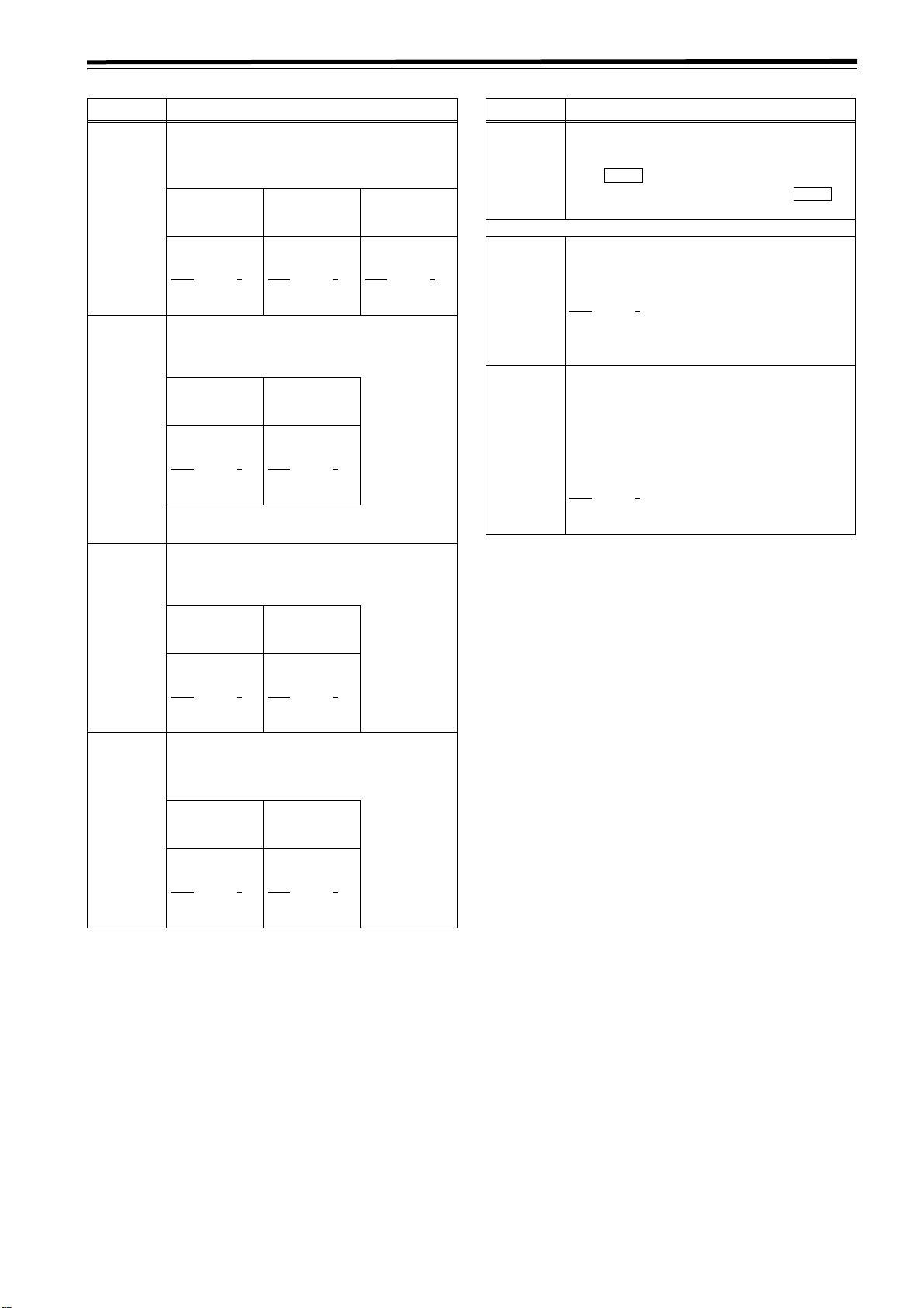
When “CMPST” has been selected as the setup menu item
No.650 (STYLE) setting
Setting Adjustment item
05:
ENCODER
SEL
REMOTE HD
LOCAL HD
BOTH HD
External encoder remote controller:
Only adjustments of the external encoder remote
controller are performed.
This unit:
Only adjustments of the setup menu items are performed.
External encoder remote controller/This unit:
Adjustments can be performed from both the external
encoder remote controller and setup menus.
06:
V LEVEL
CTRL
SD
BOTH
SD
BOTH
SD
BOTH
662: V LEVEL
663: C LEVEL
664: HUE
665: SETUP LVL
External encoder
remote controller
This unit
External encoder
remote controller/This
unit
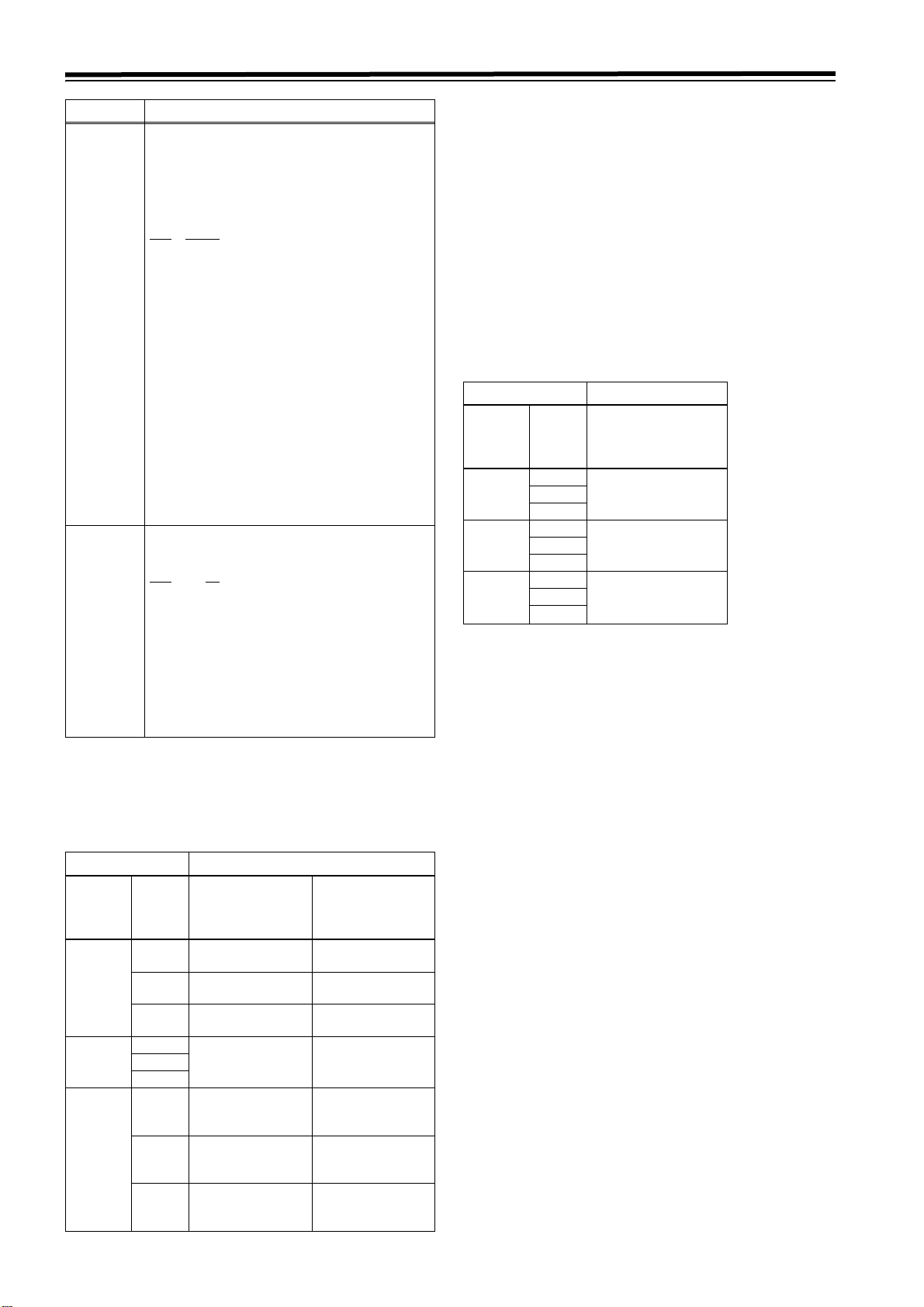
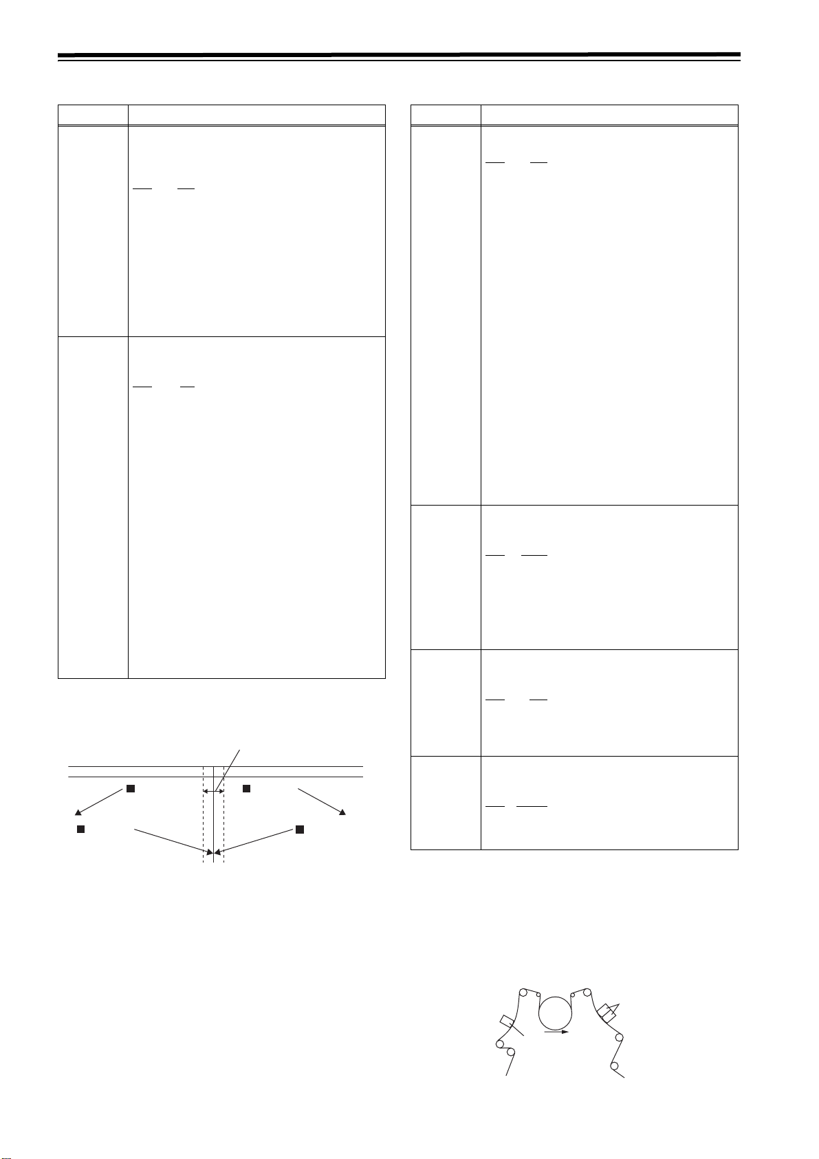
Video output signal adjustments
The control matrix for the adjustments is shown in the table
below.
Setting Adjustment item
05:
ENCODER
SEL
REMOTE HD
LOCAL HD
BOTH HD
06:
V LEVEL
CTRL
SD
BOTH
SD
BOTH
SD
BOTH
653: Y LVL (HD)
654: Pb LVL (HD)
655: Pr LVL (HD)
656: BK LVL (HD)
External encoder
remote controller
No adjustments
possible
External encoder
remote controller
This unit This unit
External encoder
remote controller/
this unit
This unit
External encoder
remote controller/
This unit
658: Y LVL (SD)
659: Pb LVL (SD)
VL (SD)
660: Pr
661: BK LVL (SD)
No adjustments
possible
External encoder
remote controller
External encoder
remote controller
This unit
External encoder
remote controller/
this unit
External encoder
remote controller/
this unit
<Note>
Use the MT-2000 (manufactured by Musashi and
recommended by Panasonic) as the external encoder
remote controller. However, its VIDEO PHASE, SYNC
PHASE and SC PHASE controls will not work.
80
Page 3
System menus (continued)
No./Item Description of setting
12
SYS H
*UP
(HD)
14
SYS SC
*DW
(SD)
15
VO SYS
H (SD)
16
SD SYS
H (SD)
*DW
*DW
For adjusting the HD SDI output system phase
in 13.5nS steps.
j: To advance the phase. i: To delay the phase.
<59/60Hz> <23/24Hz>
0
0
0000 -2750
: :
2750
: :
5500 2750
<50Hz>
<25Hz(HD,SD)>
<50Hz(HD,SD)>
0000 -115
: :
0115
: :
0230 115
0
0
0000 -2200
: :
2200
: :
4400 2200
For adjusting the system phase of the analog
composite output and the SD SDI output
Variable range: +/- 180 degrees or more
j: Advance, i: Delay
<59/60Hz>
<23/24Hz>
0000 -108
: :
0108
: :
0216 108
<Note>
This is disabled for 60 Hz/24 Hz.
For adjusting the system phase of the analog
composite output
37nS step
j: Advance, i: Delay
<59/60Hz,>
<23/24Hz>
0000 -1716
: :
1716
: :
3432 1716
For adjusting the system phase of the SD SDI
output
0
<50Hz>
<25Hz(HD,SD)>
<50Hz(HD,SD)>
0000 -1728
: :
1728
: :
3456 1728
0
37nS step
j: Advance, i: Delay
<59/60Hz,>
<23/24Hz>
0000 -1716
: :
1716
: :
3432 1716
0
<50Hz>
<25Hz(HD,SD)>
<50Hz(HD,SD)>
0000 -1728
: :
1728
: :
3456 1728
0
<50Hz>
<25Hz(HD,SD)>
<50Hz(HD,SD)>
0000 -2640
: :
2640
: :
5280 2640
No./Item Description of setting
18
SCH (SD)
Submenu screen
00
0
COARSE
01
FINE
For adjusting the SCH (Sub Carrier to
Horizontal) phase of the analog composite
*DW
output
SHIFT
Press to move to the sub menu window. To
return from the sub menu window, press
again.
For adjusting the SCH phase in 90o steps
(The SC phase changes, and the H phase remains
unchanged.)
0000 0
0001: 90
0002: 180
0003: 270
For adjusting the SCH phase over a total
variable range of more than d45o.
: To advance the phase. i: To delay the phase.
j
SHIFT
(The SC phase changes, and the H phase
remains unchanged.)
0000 -32
: :
0032
: :
0064 32
0
The underlining (__) denotes the factory setting mode.
*UP: This is for HD outputs (during HD tape playback or up-
conversion outputs).
*DW: This is for SD outputs (during SD tape playback or
down-conversion outputs).
81
Page 4
System menus (continued)
No./Item Description of setting
20
AV PH A S E
25
SYSTEM
1
FREQ*
For adjusting the phase of the AUDIO output
with the VIDEO output
20.8 microsecond steps
−: The phase of audio output advances with
respect to image output.
+: The phase of audio output delays with
respect to image output.
0000 -100
: :
0100
: :
0200 100
For selecting the system frequency.
0000 59/60
The 59.94 Hz or 60 Hz system frequency is
selected.
0001 50i/25P*
The 50 Hz or 25 PsF system frequency is
selected.
At this setting, the 1080/25 PsF format signals
can be recorded and played back in the same
way as with the 1080/50i format.
0002 23/24
The 23.98 Hz or 24 Hz system frequency is
selected.
0003 25(HD)
The 25 Hz system frequency is selected.
However, SD SDI output and analog composite
output are delayed with respect to HD SDI output
by about one field.
0004 25(SD)
The 25 Hz system frequency is selected.
However, the black signal is output from HD SDI
output.
0005 50(HD)
The 50 Hz system frequency is selected.
However, SD SDI output and analog composite
output are delayed with respect to HD SDI output
by about one field.
0006 50(SD)
The 50 Hz system frequency is selected.
However, the black signal is output from HD SDI
output.
59/60Hz mode A state selecting 0 (59/60)
50Hz mode A state selecting 1 (50i/25P)
23/24Hz mode A state selecting 2 (23/24)
25Hz(HD) mode A state selecting 3 (25 (HD))
25Hz(SD) mode A state selecting 4 (25 (SD))
50Hz(HD) mode A state selecting 5 (50 (HD))
50Hz(SD) mode A state selecting 6 (50 (SD))
<Note>
For the procedure to shift the system frequency,
refer to page 112.
2
The asterisk denotes the factory setting for
*
AJ-HD1800E.
0
2
No./Item Description of setting
26
HD SYS H ADV
30
MENU LOCK
*1System switching
z Some of the system menu and setup menu items each have
different settings for different operation modes [59/60 Hz, 50 Hz,
23/24 Hz, 25 Hz (HD or SD) and 50 Hz (HD or SD)]. These
settings are saved separately.
For selecting the output whose HD output
phase is to be advanced by 90H in relation to
the SD output.
0000 0H
Both the HD and SD signals are output in phase
with the HD and SD REF output signals.
0001 90H
The HD signals are output at a phase advanced
by 90H from the SD output signals.
When the SD REF signal is input, the REF input
and SD output are in-phase, and when the HD
REF signal is input, the REF input and HD output
are inphase.
<Notes>
z The audio signals and TC signal are output in
phase with the HD output.
z With the 720p format, there is a phase difference
of 120H between them.
For selecting whether to set or release the
system file lock mode.
0000 OFF
Lock released (changes enabled)
0001 ON
Lock set (changes prohibited)
<Notes>
Even if [ON] is selected, the file is overwritten when
the system file is retrieved from an SD memory
card.
(This concerns those items whose settings were described for
each operation mode on the system menu and setup menu
tables.)
z For further details, refer to <Menu management accompanying
switching the system frequency> on page 113.
z Since this VTR becomes a playback-only unit when the 23/24
Hz, 25 Hz (HD or SD) or 50 Hz (HD or SD) mode has been
selected, the functions relating to EE, recording and editing
are all set to the inhibited status. Neither is it possible to
select CTL in such a case.
(The related menus and function buttons are not displayed,
and operation is prohibited.)
For the instant when the tape begins to run at the 1k speed
such as when it starts playing from the STOP status, the
image is disrupted and the sound is muted for several
frames because the tape is being synchronized with the REF
input.
The underlining (__) denotes the factory setting mode.
82
Page 5
Setup menus
<BASIC>
No./Item Description of setting
000
P-ROLL TIME
001
LOCAL ENA
For setting the preroll time. Any time from 0 to
30 seconds can be set in 1-second increments.
0000 0s
: :
0005
: :
0030 30s
<Notes>
z During automatic editing (PREVIEW or AUTO
z If the phases are to be synchronized between
For selecting the transport system buttons
which can be operated on the front panel in the
REMOTE mode.
0000 DIS
0001 ST&EJ
0002 ENA
<Note>
5s
EDIT), no operations are performed if the preroll
time is set to 0 seconds.
two decks for editing as per the setup menu item
No.004 (SYNCHRONIZE) setting, set the preroll
time to at least 2 seconds.
No buttons can be operated.
Only the STOP and EJECT buttons can be operated.
ll the buttons except for the RECORDER and
PLAYER buttons can be operated.
The following buttons and dials function at all
times regardless of this setting:
Audio input/output level control dials, audio
channel selector buttons, number keys, function
buttons, direct menu button, ASSEM button,
INSERT button, ADJ dial, headphone volume
control dial, MONITOR SELECT button, METER
(FULL/FINE) selector switch, REMOTE button.
*1
002
TAPE TIMER
003
REMAIN SEL
*1 When the 23/24 Hz mode, 25 Hz (HD, SD) mode, or 50 Hz
(HD, SD) mode is selected in System Menu No. 25 (SYSTEM
FREQ), this item is not displayed.
For selecting the 12- or 24-hour system for the
CTL counter display.
0000 ±12h
12-hour system display
0001 24h
24-hour system display
For selecting whether or not to display REMAIN
(remaining tape time) on the superimposed
display of the HD SDI MONITOR, SD SDI
MONITOR and VIDEO OUT3 connectors.
0000 OFF
The remaining tape time is not displayed.
0001 2L
The remaining tape time is displayed on the second line.
0002 1L
The remaining tape time is displayed on the first
line.
0003 R/TTL
The remaining tape time is displayed on the first
line, and the total tape time is displayed on the
second line.
<Notes>
z When setting 1 (2L) has been selected, the
remaining tape time is not displayed if 0 (TIME)
is selected as the setup menu item No.006
(DISPLAY SEL) setting.
z When setting 3 (R/TTL) has been selected, the
remaining tape time is not displayed if 0 (TIME)
is selected as the setup menu item No.006
(DISPLAY SEL) setting.
*The underlining (__) denotes the factory setting mode.
No./Item Description of setting
*1
004
SYNCHRONIZE
005
SUPER
006
DISPLAY SEL
For setting whether or not to synchronize the
phases between two decks.
0000 OFF
The phases are not synchronized. The edit
points will be off by several frames but editing will
be commenced more promptly.
0001 ON
The phases are synchronized. Error-free editing
can be performed.
For selecting whether or not to superimpose
the display of the time code or other data onto
the HD SDI MONITOR, SD SDI MONITOR and
VIDEO OUT3 connectors.
0000 OFF
The time code or other data is not displayed.
0001 ON
The time code or other data is displayed.
<Note>
z The 1394 output follows the settings in Setup
Menu No. 899 (DIF SUPER).
z When the 23/24 Hz mode, 25 Hz (HD) mode, or
50 Hz (HD) mode is selected in System Menu
No. 25 (SYSTEM FREQ), supers, such as time
codes, are not displayed on the SD SDI
MONITOR/VIDEO OUT 3 connector. When the
25 Hz (SD) mode or 50 Hz (SD) mode is
selected, supers, such as time codes, are not
displayed on the HD SDI MONITOR connector.
For selecting the time code and other displays
to be superimposed onto the HD SDI MONITOR,
SD SDI MONITOR and VIDEO OUT3 connectors.
In the following descriptions, [DATA] refers to the
values for CTL/TC/UB selected in (TC/CTL).
0000 TIME
Only data are displayed.
0001 T&STA
Data and operating conditions are displayed.
0002 T&S&M
Data, operating conditions, and the mode are
displayed
0003 T&RT
Data and REC TIME are displayed.
0004 T&YMD
Data and REC DATE (Year/Month/Day) are
displayed.
0005 T&MDY
Data and REC DATE (Month/ Day/Year) are
displayed.
0006 T&DMY
Data and REC DATE (Day/Month/Year) are
displayed.
0007 T&UB
Data and user bits are displayed.
However, when UB is selected in (TC/CTL)
of the HOME menu, the time code is displayed
immediately after user bits.
0008 T&CTL
Data and CTL are displayed.
However, when CTL is selected in (TC/CTL)
of the HOME menu, the time code is displayed
immediately after CTL data.
0009 T&T
Data and the time code are displayed.
<Notes>
z When setting 2 (T&S&M) is selected, an error
message appears if a warning or error has
occurred.
z REC TIME and REC DATE are displayed only
during DV or DVCAM format playback. The
operation mode is displayed when the DVCPRO
HD-LP, DVCPRO HD, DVCPRO50 or DVCPRO
format is used.
F3
F3
F3
83
Page 6
Setup menus (continued)
<BASIC> (continued)
No./Item Description of setting
007
CHARA
H-POS
008
CHARA
V-POS
009
CHARA TYPE
For setting the character position in the
horizontal direction for superimposed
indications, such as time codes for HD SDI
MONITOR/SD SDI MONITOR/VIDEO OUT3
connectors and superimposed indications from
the IEEE 1394 digital interface.
0000 0
: :
0006
: :
0037 37
<Note>
When this menu item has been set, the displays
are output to the HD SDI MONITOR, SD SDI
MONITOR and VIDEO OUT3 connectors in the
DISPLAY SEL status even when the SUPER OFF
setting is established. However, if the menu has
been exited, the SUPER OFF or ON setting is
followed.
Furthermore, CHARA TYPE is output as per the
menu setting.
For setting the character position in the vertical
direction for superimposed indications, such as
time codes for HD SDI MONITOR/SD SDI
MONITOR/VIDEO OUT3 connectors and
superimposed indications from the IEEE 1394
digital interface.
0000 0
: :
0023
: :
0032 32
<Note>
When this menu item has been set, the displays
are output to the HD SDI MONITOR, SD SDI
MONITOR and VIDEO OUT3 connectors in the
DISPLAY SEL status even when the SUPER OFF
setting is established. However, if the menu has
been exited, the SUPER OFF or ON setting is
followed.
Furthermore, CHARA TYPE is output as per the
menu setting.
For setting the display type for the
superimposed displays and for the HD SDI
MONITOR, SD SDI MONITOR and VIDEO OUT3
connectors and superimposed indications from
the IEEE 1394 digital interface as well as for the
SETUP MENU, etc.
6
23
No./Item Description of setting
011
CU-ROLL
TIME
015
AUTO
STEP
*1
020
SYS FORMAT
*1 When the 23/24 Hz mode, 25 Hz (HD, SD) mode, or 50 Hz
(HD, SD) mode is selected in System Menu No. 25 (SYSTEM
FREQ), this item is not displayed.
For setting the preroll time in the MULTI CUE
mode.
Any time from 0 to 15 seconds can be set in 1second increments.
0000 0s
: :
0005 5s
: :
0015 15s
For selecting the save processing to be
conducted when the memory capacity, which
enables up to 99 warning messages to be
saved, has been exceeded while the error log
function is operating.
0000 OFF
99 messages are set as the upper limit, and any
more warning messages which subsequently
occur are not saved in the memory.
0001 ON
99 messages are saved, and the next warning
message that has subsequently occurred is
saved as No.99. The warning messages already
saved are each shifted down by one number in
succession.
For selecting the recording and playback
formats including HD REF signals
0000 1080i
The 1080i format is selected.
0001 720p
The 720p format is selected.
The underlining (__) denotes the factory setting mode.
*1
010
MONI
CONTROL
84
0000 WHITE
White characters on a black background.
0001 W/OUT
White characters with black borders.
<Note>
CHARA TYPE is output as per the menu setting.
For setting whether to forcibly set the recorder
to the EE mode and output the player’s
playback signals to the monitor if the PLAYER
button on the recorder is pressed when the
monitor is connected only to the recorder
during deck-to-deck editing.
0000 MANU
The recorder is not forcibly set to the EE mode.
0001 AUTO
The recorder is forcibly set to the EE mode, and the
player’s playback signals are output.
Page 7
Setup menus (continued)
<BASIC> (continued)
No./Item Description of setting
022
PB FORMAT
023
FORMAT
SEL
1
030*
HD
FREQUENCY
For selecting the format in which the tape is to
be played back.
0000 MANU
The format is determined by the setting selected
for setup menu item No.023 (FORMAT SEL).
0001 AUTO 1
The unit follows the format recorded on the tape.
Whenever the format is changed during
playback, the playback format switches to others
according to the changed format.
0001 AUTO 2
If the playback format does not change for 1
second or more after the SERVO lamp lights
when starting playback, the current playback
format is fixed. The fixed playback format is
retained as is even if the format recorded on the
tape is changed unless the playback mode is
released.
For selecting the format when “MANUAL” has
been selected as the setup menu item No.022
(PB FORMAT) setting.
If “AUTO” is selected as the setting, the format
when playback starts is selected, and when the
tape is played back, the format is automatically
detected and matched with the format of the
playback tape.
0000 HD-LP
The DVCPRO HD-LP format is selected, and the
setup menu item No.020 (SYS FORMAT) setting
is followed.
0001 HD-SP
The DVCPRO HD format is selected, and the
setup menu item No.020 (SYS FORMAT) setting
is followed.
0002 422
The DVCPRO50 (422) format is selected.
0003 411
The DVCPRO (411) format is selected.
0005 DV
The DV format is selected.
0006 DVCAM
The DVCAM format is selected.
For setting the field system frequency
0000 59/23
The 59.94/23.98 Hz frequency is set.
0001 60/24
The 60/24 Hz frequency is set.
<Notes>
z The set field frequency is enabled only when
there is no input for the OUT REF settings. If
there are any corresponding inputs, the field
frequency coincides with the field frequency of
the input.
z When the HD SDI output is output with 60 Hz/24
Hz, the SD SDI is output as NO SYNC, and the
analog composite is output in the White/Black
mode (burst off).
No./Item Description of setting
2
031*
OUT REF
Video output reference
0000 AUTO
When the HD REF input signal is supplied, it is
used as the reference. If it is not supplied but the
SD REF input signal is supplied, the SD REF
signal serves as the reference instead.
If neither the HD REF nor SD REF input signal is
supplied, the HD serial signal serves as the
reference.
If none of the HD REF, SD REF and HD serial
signals are supplied, the internal sync signal
serves as the reference.
0001 INPUT
When the serial input signal is supplied, it is used
as the reference
0002 HD_REF
The signal which is input to the HD REF IN
connector is used as the reference.
0003 SD_REF
The signal which is input to the SD REF IN
connector is used as the reference.
0004 E-AUTO
In edit mode, the state is the same as set in
[INPUT]. In modes other than edit mode, the
state is the same as set in [AUTO].
<Note>
.
For details, refer to [Playback reference signal
specifications for tape playback
*1: When the 50 Hz mode, 25 Hz (HD, SD) mode, or 50 Hz (HD,
SD) mode is selected in System Menu No. 25 (SYSTEM
FREQ), this item is not displayed.
*2: When the 23/24 Hz mode is selected in System Menu No. 25
(SYSTEM FREQ), this item is not displayed.
] (page 45).
*The underlining (__) denotes the factory setting mode.
85
Page 8
Setup menus (continued)
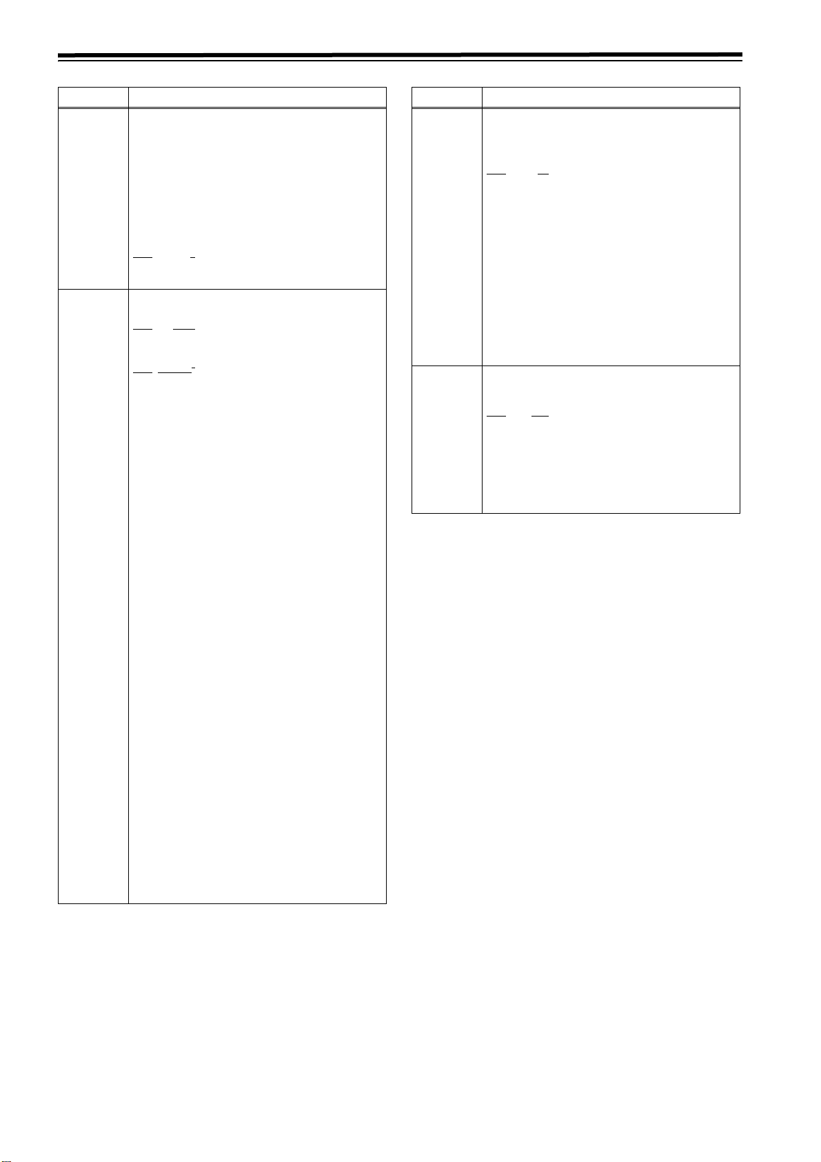
<BASIC> (continued)
Formats in which the tape is played back
022:
PB
FORMAT
MANUAL 1080i HD_LP DVCPRO HD-LP(1080i)
AUTO -------- -------- DVCPRO HD-LP(1080i)/
<Notes>
z In the EJECT mode, the format selected by the setup
menu item No.020 (SYS FORMAT) setting applies.
z If “AUTO” has been selected as the setup menu item
No.022 (PB FORMAT) setting, the setup menu item
No.023 (FORMAT SEL) setting is used as the format when
the format is not detected (when the tape has just been
inserted).
However, when “DV” or “DVCAM” has been selected, the
VTR operation will be as if “HD-LP” has been selected.
020:
SYS
FORMAT
720p HD_LP DVCPRO HD-LP(720p)
023:
FORMAT
SEL
HD_SP DVCPRO HD(1080i)
50M DVCPRO50(422)
25M DVCPRO(411)
DV DV
DVCAM DVCAM
HD_SP DVCPRO HD(720p)
50M DVCPRO50(422)
25M DVCPRO(411)
DV DV
DVCAM DVCAM
Playback format
DVCPRO HD(1080i)/
DVCPRO HD-LP(720p)/
DVCPRO HD(720p)/
DVCPRO50(422)/
DVCPRO(411)/
DV/DVCAM, automatic
detection
86
Page 9
Setup menus (continued)
<OPERATION>
No./Item Description of setting
100
SEARCH ENA
101
SHTL MAX
102
FF. REW MAX
104
REF ALARM
*1
105
AUTO EE SEL
*1: When the 23/24 Hz mode, 25 Hz (HD, SD) mode, or 50 Hz
(HD, SD) mode is selected in System Menu No. 25 (SYSTEM
FREQ), this item is not displayed.
For selecting the direct search dial operation.
0000 DIAL
Direct search dial operations are performed.
0001 KEY
Unless the search button is pressed, the mode
does not change to the search mode.
For selecting the maximum speed of shuttle
operations.
0000 x9.8
k9.8 times normal speed
0001 x16
k16 times normal speed
0002 x32
k32 times normal speed
<Note>
Depending on the tape format, the actual tape
running speed differs slightly from what is indicated
by the superimposed display.
For setting the maximum speed of fast forward
and rewind operations.
0000 x16
k16 times normal speed
0001 x32
k32 times normal speed
0002 x50
k50 times normal speed
0003 x60
k60 times normal speed
0004 x100
k100 times normal speed
<Note>
The maximum speed is automatically limited to
50k for the DVCPRO HD and DVCPRO50 format
and to 32k for the DV and DVCAM formats.
For selecting whether a warning is to be
displayed when the REF VIDEO signal has not
been connected.
0000 OFF
A warning is not displayed.
0001 ON
A warning is displayed by the blinking STOP
lamp.
For selecting the VTR mode which is to be set
to the EE mode when “0 (EE)” is selected as the
setup menu item No.140 (OUTPUT) setting.
0000 S/F/R
The EE mode is established when the VTR is in
the STOP, FF or REW mode.
0001 STOP
The EE mode is established when the VTR is in
the STOP mode only.
No./Item Description of setting
106
EJECT EE SEL
1
107*
EE MODE SEL
For selecting the video and audio output
statuses in the EJECT mode.
0000 EE
The EE mode is always established regardless of
the setup menu item No.140 (OUTPUT) setting.
0001 BLACK
When setup menu item No.140 (OUTPUT) is set
to:
“EE”: The EE mode is established
“TAPE”: The BLACK mode is established for the
video signals, and the audio signals are
muted.
0002 GRAY
When setup menu item No.140 (OUTPUT) is set
to:
“EE”: The EE mode is established
“TAPE”: The GRAY mode is established for the
video signals, and the audio signals are
muted.
<Note>
If [EE] is selected when the 23/24 Hz or 25 Hz (HD,
SD), 50 Hz (HD, SD) mode is selected in System
Menu No. 25 (SYSTEM FREQ), images are output
in BLACK and voices are muted.
For selecting what signals are to be output
when the EE mode is established.
0000 NORMAL
Signals delayed by an amount equivalent to the
time taken for the signals to be processed internally are output.
0001 THRU
The signals are not processed internally but output in their original form with no delay.
<Note>
When 1394 or INT-SG is selected in the video
input, the system operates as “NORMAL”
regardless of the settings in this item.
108
PLAY DELAY
1
109*
CAP. LOCK
110
AUTO REW
For setting the play startup time in 1-frame
increments.
0000 0
: :
0015 15
For selecting the field unit for locking the
playback framing.
<59/60Hz> <50Hz>
0000
00014F00014F
For selecting whether the tape is to be
automatically wound back to its beginning
when the tape-end has been detected.
0000 OFF
0001 ON
2F 0000 2F
0002 8F
The tape stops when it reaches the tape-end.
The tape is rewound to its beginning.
.
.
The underlining (__) denotes the factory setting mode.
87
Page 10
Setup menus (continued)
<OPERATION> (continued)
No./Item Description of setting
1
111*
MEMORY
STOP
112
FRZ MODE
SEL
For selecting whether to automatically stop the
VTR when the counter value is at the “0”
position during CTL mode FF and REW
operations.
0000 OFF
The VTR does not stop.
0001 ON
The VTR is automatically stopped.
<Notes>
z Either the stop or still picture (SHTL STILL or
SLOW STILL) mode, whichever has been set
using setup menu item No.307 (AFTER CUE-
UP), is established when the VTR is stopped.
z If both the AUTO REW function and MEMORY
function have been selected at the same time,
the AUTO REW operation takes priority.
For selecting what playback images are to be
output in the STANDBY OFF (HALF LOADING)
mode and EJECT mode.
0000 DIS
The video output is muted.
0001 STB OFF
Only when the STANDBY OFF mode is estab-
lished is the image which was being played back
at that moment frozen and output.
0002 SOF&EJ
When either the STANDBY OFF mode or the
EJECT mode is established, the image which
was being played back at that moment is frozen
and output.
<Notes>
z The status when the picture is frozen is
determined by the setup menu item No.604
(FREEZE SEL) setting.
z In the EJECT mode, the frozen picture is output
only when 1 (BLACK) or 2 (GRAY) has been
selected as the setup menu item No.106 (EJECT
EE SEL) setting.
z When the 720/24p over 60p source is used and
the 23/24 mode is selected in System Menu item
No. 25 (SYSTEM FREQ), playback cannot be
frozen in EJECT mode.
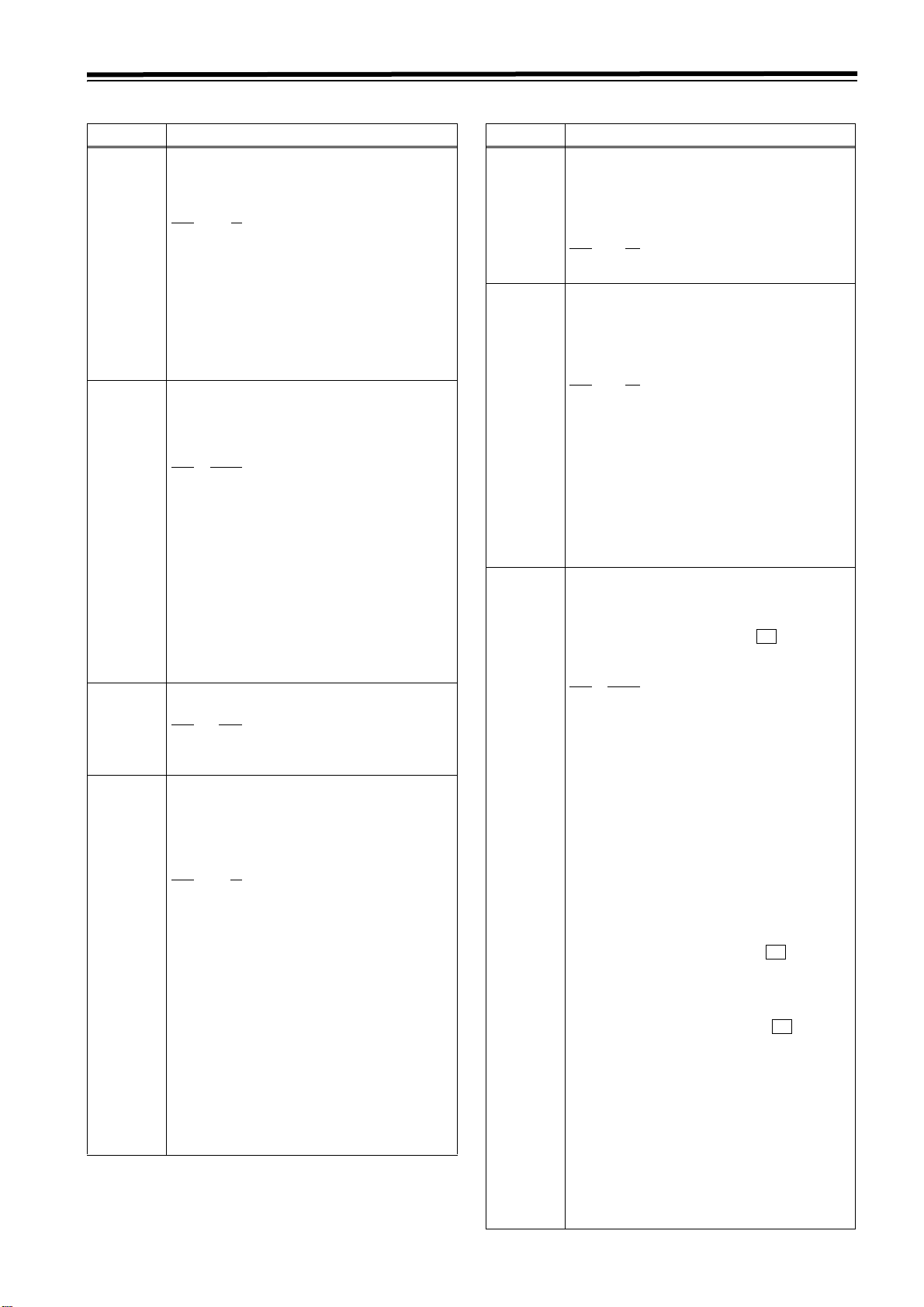
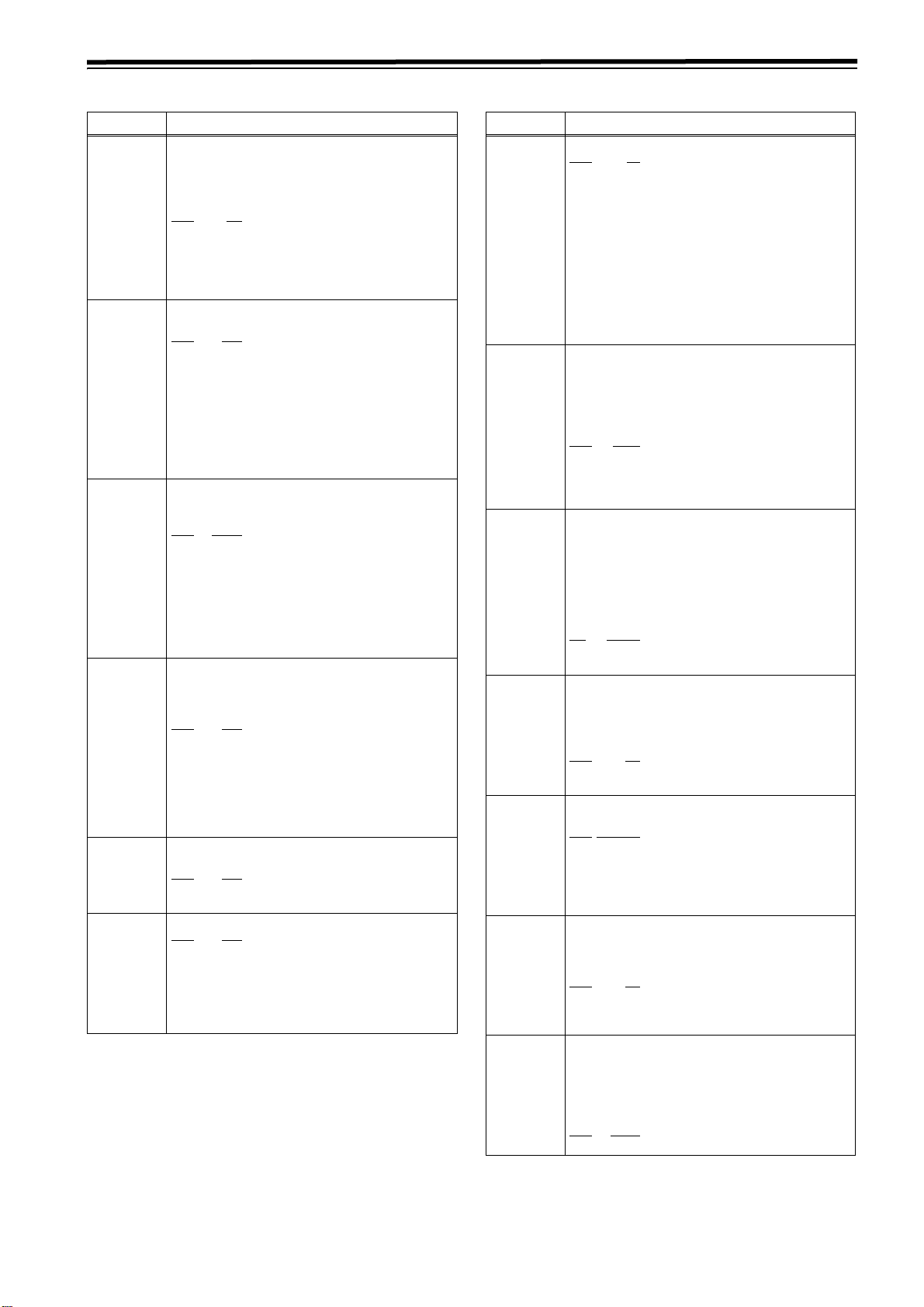
Description of MEMORY STOP function
The MEMORY STOP function does
not work if this margin is less than 0
d
2 frames.
FF button
1
2
FF button
4
REW button
3
0 point
REW
button
No./Item Description of setting
*1
113
REC INH
114
REC INH
LAMP
*1
115
EJECT SW
INH
116
EJECT LAMP
For selecting whether to allow or inhibit
recording on the cassette tape.
0000 OFF
Recording on the cassette tape is enabled when
the cassette’s accidental erasure prevention
mechanism has been set to the recording enable
position.
0001 ALL
All recording on the cassette tape is inhibited.
0002 PRE
Overwriting is inhibited during normal recording.
This is the setting to activate the accidental
erasure prevention function. While CTL is
detected, the recording is inhibited, and when
CTL cannot be detected, it is executed.
0003 NORM
Normal recording is inhibited.
Use this setting when it is preferable to avoid
using normal recording in all applications except
for editing.
0004 V/CTL
The recording of the video and CTL signals is
inhibited.
Use this setting when it is preferable to avoid
editing in all applications except for audio editing.
<Note>
When the PRE, NORM or V/CTL setting has been
selected, the REC INHIBIT lamp blinks (on for
approx. 0.5 sec. and then off for approx. 0.5 sec.).
For selecting whether the REC INHIBIT lamp is to
blink or light when the cassette tape has been set
to the accidental erasure protection mode.
0000 LIGHT
The lamp lights.
0001 FLASH
The lamp blinks.
<Note>
When Setup Menu No. 113 (REC INH) is set to
[ALL], the REC INHIBIT LAMP always lights
regardless of the setting.
For selecting whether to enable or disable the
operation of the EJECT button on the VTR’s
front panel.
0000 REC
Operation is disabled while the VTR is in the
recording mode.
0001 OFF
Operation is enabled in all modes.
For selecting whether the EJECT lamp is to
remain lighted or go off after the cassette tape
has been ejected.
0000 MODE1
The EJECT lamp remains lighted.
0001 MODE2
The EJECT lamp goes off.
! If the FF button is pressed, the normal FF operation is
performed since there is no 0 point in the direction of this
operation.
@ If the REW button is pressed, the PREROLL lamp lights (as
does the SHTL lamp), the VTR prerolls the tape, and it
automatically stops when the counter value is at the 0 position.
# If the REW button is pressed, the normal REW operation is
performed since there is no 0 point in the direction of this
operation.
$ If the FF button is pressed, the PREROLL lamp lights (as does
the SHTL lamp), the VTR prerolls the tape, and it
automatically stops when the counter value is at the 0 position.
*1: When the 23/24 Hz mode, 25 Hz (HD, SD) mode, or 50 Hz
(HD, SD) mode is selected in System Menu No. 25 (SYSTEM
FREQ), this item is not displayed.
88
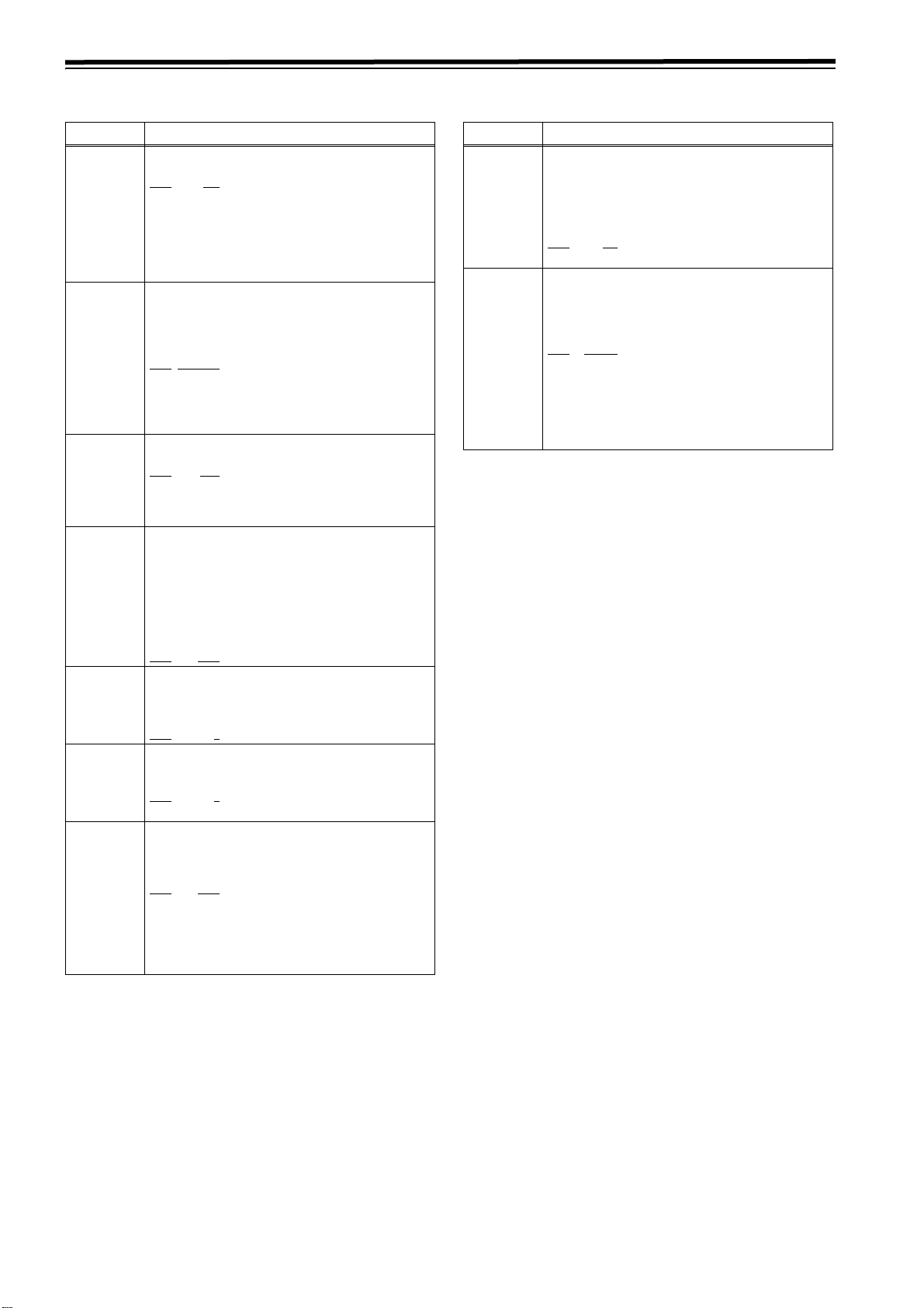
Accidental erasure protection function
This function is used to prevent parts already recorded on a tape
from being recorded over. Accidental erasure of pre-recorded
tapes is prevented by positioning the CTL signal rec/play heads as
shown in the figure below so that whether a recording has been
made can be determined by the presence or absence of the CTL
signal. When the REC/PLAY button is pressed with a prerecorded tape, the tape runs but the REC button lamp blinks, the
beeping alarm is sounded, and no signals are recorded.
A/C heads
(rec/play heads)
PRE CTL
head
Rough sketch showing CTL head positions
Page 11
Setup menus (continued)
<OPERATION> (continued)
No./Item Description of setting
1
118*
SP MODE
INH
1
119*
CONFI REC
131
PAG E M O DE
132
ROTA MODE
133
KEY BEEP
134
ALARM BEEP
*1 When the 23/24 Hz mode, 25 Hz (HD, SD) mode, or 50 Hz
(HD, SD) mode is selected in System Menu No. 25 (SYSTEM
FREQ), this item is not displayed.
For selecting whether to allow or inhibit
recording on a tape which has been written by a
format other than DVCPRO HD-LP.
0000 OFF
Recording on the cassette tape is allowed.
0001 ON
Recording on the cassette tape is inhibited.
<Note>
When [OFF] is selected, the inhibition/permission
state for recording to a cassette tape follows Setup
Menu No. 113 (REC INH).
For selecting whether or not to perform simultaneous playback during normal recording.
0000 OFF
According to the settings in Setup Menu No. 140
(OUTPUT), the simultaneous playback operation
during normal recording shifts.
EE :EE output
TA PE :Simultaneous playback output
0001 ON
Regardless of the settings in Setup Menu No.
140 (OUTPUT), simultaneous playback is always
applied during normal recording.
For selecting what cue point operation is to be
performed when the multi cue function has
been set to ON.
0000 MANU
Operation is confined within the selected page,
and 6 cue points can be registered.
0001 AUTO
When the page whose cue points are being registered becomes full, operation is automatically
transferred to the next page, and registration is
continued. A total of 60 cue points on up to 10
pages can be registered.
For selecting whether to perform the
registration operation if all the cue points have
already been registered when the multi cue
function has been set to ON.
0000 OFF
No further cue points are registered.
0001 ON
The registration operation is continued. If “MANU”
has been selected as the setup menu item No.131
(PAGE MODE) setting, the next cue point is
registered at CUE
“AUTO” has been selected, it is registered at CUE01.
For setting the volume of the sound heard when
the keys are touched.
0000 OFF
0001 LOW
0002 HIGH
For setting the volume of the alarm tone.
0000 OFF
0001 LOW
0002 HIGH
<Note>
If the fan motor has shut down, the alarm tone is
sounded at the HIGH volume level regardless of
this setting.
¢
1 on the page concerned; if
No./Item Description of setting
1
140*
OUTPUT
For selecting the output signals.
0000 EE
The input signals selected by setup menu items
No.600 (VIDEO IN SEL) and No.713 (CH1 IN
SEL) to No.724 (D IN SEL 78) are output.
0001 TAPE
<In the STOP mode>
The signals played back from the tape are output.
<During recording or editing>:
The simultaneous playback signals are output.
<Note>
Output signals when recording and editing are
selected in Setup Menu No. 119 (CONFI REC)
and No. 302 (CONFI EDIT).
1
141*
VOLUME
1
142*
AUDIO UNITY
143
CASSTT
LIGHT
144
TC INPUT
145
FRONT LCD
146
SAVER DISP
For setting what is to be controlled by the audio
volume controls on the front panel.
0000 REC
The controls function as REC volume controls.
0001 PB
The controls function as PB volume controls.
0002 AUTO
Normally, the controls function as PB volume
controls. However, during recording or in the EE/
INPUT CHECK status, they automatically function as REC volume controls.
For selecting the conditions under which the
AUDIO UNITY lamp on the front panel is to light.
0000 IN
The lamp lights when all the audio input levels
are set to the UNITY level.
0001 OUT
The lamp lights when all the audio output levels
are set to the UNITY level.
002 IN/OUT
The lamp lights when all the audio input and output levels are set to the UNITY level.
For setting whether the lighting of the tape
mechanism is to be set to ON or remain OFF.
0000 OFF
The mechanism does not light even when a cassette is inserted.
0001 ON
The mechanism lights when a cassette is
inserted.
For switching the preset registration method for
the time code.
0000 NORMAL
The time code is input starting with the left-most
digit.
0001 REV
The time code is input from the high-order digit
but is displayed from the right-most digit.
For selecting whether the LCD monitor display
on the front panel is to be turned on or off.
0000 OFF
The display is turned off.
0001 ON
The display is turned on or off in synchronization
with the screen saver operation for the time code
display area.
If the front operation or tape operation is not
executed for some while, the time code display
switches to the screen saver display.
For selecting the screen saver display format.
0000 BLACK
To the black display
0001 LOGO
To display [EX] logo animation
89
Page 12
Setup menus (continued)
<INTERFACE>
No./Item Description of setting
200
PARA RUN
202
ID SEL
204
RS2323C SEL
205
BAUD RATE
206
DATA
LENGTH
207
STOP BIT
208
PA RI T Y
For selecting whether to operate two or more
VTRs in synchronization.
0000 DIS
The VTRs are not operated in synchronization.
0001 ENA
The VTRs are operated in synchronization.
<Note>
To operate the VTRs in synchronization, set all the
VTRs to 1 (ENA). (Refer to page 16.)
For setting what ID information is to be
returned to the controller.
0000 OTHER
For setting the ID information of a VTR other
than DVCPRO
0001 DVCPRO
For setting the ID information of the DVCPRO
0002 ORIG
Set only for connecting with the Panasonic
controller (AG-A850, optional).
For selecting whether the RS-232C connector is
to function.
0000 OFF
The RS-232C connector does not function.
0001 ON
The RS-232C connector functions.
For setting the RS-232C data transfer speed
(baud rate).
0000 300
0001 600
0002 1200
0003 2400
0004 4800
0005
For setting the RS-232C data length.
(Unit: bits)
0000 7
0001
For setting the number of RS-232C stop bits.
(Unit: bits)
0000 1
0001 2
For setting whether the RS-232C parity bit is to
be used and, if it is used, whether even or odd
parity is to apply.
9600
8
No./Item Description of setting
209
RETURN ACK
212
MASTER
PORT
For setting whether or not to return the ACK
code when a command is received from RS232C.
0000 OFF
The ACK code is not returned
0001 ON
The ACK code is returned.
For selecting the remote control connector for
controlling the slave machine when this VTR is
to be used as the master machine for deck-todeck operations.
0000 IN/OUT
The IN/OUT connector is used.
0001 OUT
The OUT connector is used.
<Note>
This setting takes effect only when the 9P button
has been set to LOCAL (LED off).
0000 NON
The parity bit is not used.
0001 ODD
The parity bit is used with an odd parity.
0002 EVEN
The parity bit is used with an even parity.
The underlining (__) denotes the factory setting mode.
90
Page 13

Setup menus (continued)
<EDIT>
No./Item Description of setting
300
IN/OUT DEL
301
NEGA FLASH
1
302*
CONFI EDIT
For selecting the operation to be performed
when an edit point has been set incorrectly
(when the OUT point comes before the IN
point).
0000 MANU
Editing is not performed unless the illegal edit
point is cleared or set properly.
0001 AUTO
The edit point which had already been input is
cleared automatically.
For selecting whether to show a negative
display (time code display area) when the IN
point is greater than the OUT point.
0000 OFF
A negative display is not shown.
0001 ON
A negative display is shown.
For selecting whether to perform simultaneous
playback during editing.
0000 OFF
Simultaneous playback is not performed.
0001 ON
Simultaneous playback is performed.
<Note>
Regardless of the settings in Setup Menu No. 140
(OUTPUT), simultaneous playback is always
performed during editing.
*
1
303
AUD EDIT
IN
*
1
304
AUD EDIT OUT
305
AUTO ENTRY
*
1
306
CF ADJ SEL
307
AFTER
CUE-UP
For selecting how to connect the digital audio
edit IN points.
0000 CUT
Cut processing
0001 FAD E
V-fade processing
For selecting how to connect the digital audio
edit OUT points.
0000 CUT
Cut processing
0001 FAD E
V-fade processing
For selecting whether to register the IN points
using the PREROLL button in cases where the
IN points have not been registered.
0000 DIS
The IN points are not registered.
0001 ENA
The IN points are registered
For selecting the deck whose the color framing
is to be adjusted during deck-to-deck editing.
0000 PLAYER
The player’s IN and OUT points are adjusted
(using the recorder as the reference).
0001 RECORD
The recorder’s IN and OUT points are adjusted
(using the player as the reference).
For selecting the VTR’s mode upon completion
of the cue-up operation.
0000 STOP
The VTR is set to the STOP mode.
0001 STILL
The VTR is set to the still picture (SHTL STILL)
mode.
0002 STILL2
The VTR is set to the still picture (SLOW STILL)
mode.
No./Item Description of setting
308
VAR FWD MAX
309
VAR R E V M AX
310
JOG FWD
MAX
311
JOG REV MAX
1
312*
POSTROLL
TM
*1 When the 23/24 Hz mode, 25 Hz (HD, SD) mode, or 50 Hz
(HD, SD) mode is selected in System Menu No. 25 (SYSTEM
FREQ), this item is not displayed.
For setting the maximum speed of SLOW FWD.
0000 +4.9
i4.9 times normal tape speed
0001 +2
i2 times normal tape speed (i1.85 times
normal tape speed for formats other than
DVCPRO HD-LP)
0002 +1
i1 times normal tape speed
<Notes>
z At any setting other than 0 (i4.9), phase
adjustments cannot be conducted from the
editing controller.
z Depending on the format used, the actual tape
running speed differs slightly from what is
indicated by the superimposed display.
For setting the maximum speed of SLOW REV.
0000 -4.9
j4.9 times normal tape speed
0001 -2
j2 times normal tape speed (j1.85 times
normal tape speed for formats other than
DVCPRO HD-LP)
0002 -1
j1 times normal tape speed
<Note>
Depending on the format used, the actual tape
running speed differs slightly from what is indicated
by the superimposed display.
For setting the maximum speed of JOG FWD.
0000 +4.9
i4.9 times normal tape speed
0001 +2
i2 times normal tape speed (i1.85 times
normal tape speed for formats other than
DVCPRO HD-LP)
0002 +1
i1 times normal tape speed
<Note>
At any setting other than 0 (i4.9), phase
adjustments cannot be conducted from the editing
controller which performs these adjustments by the
JOG command.
For setting the maximum speed of JOG REV.
0000 -4.9
j4.9 times normal tape speed
0001 -2
j2 times normal tape speed (j1.85 times
normal tape speed for formats other than
DVCPRO HD-LP)
0002 -1
j1 times normal tape speed
For setting the postroll time.
Any time from 0 to 5 seconds can be set in 1second increments.
0000 0s
0001 1s
0002
0003 3s
0004 4s
0005 5s
2s
The underlining (__) denotes the factory setting mode.
91
Page 14

Setup menus (continued)
<EDIT> (continued)
No./Item Description of setting
313
When the search dial from intermediate
position turning to the right or the left with
CLICK POINT
SLOW mode, the speed in the click point is set.
0000 ±1
i/j1 time speed
0002 ±1.85
i/j1.85 time speed (i1.85/j1.5 times speed
for format DVCPRO HD-LP)
*
1
320
EDIT RPLCE1
For setting the allocation of the channels for the
analog audio presets of a controller when a
controller without a function to control the edit
presets of the digital audio signals is used to
edit the digital audio signals of the VTR.
The VTR’s CH1 edit presets are set to ON or OFF
following the analog audio signals specified by the
controller.
0000 N-DEF
Not set.
0001 CH1
The analog CH1 edit presets are followed.
0002 CH2
The analog CH2 edit presets are followed.
0003 CH1+2
The analog CH1 or CH2 edit presets are
followed.
*
1
321
EDIT RPLCE2
As with setup menu item No.320, the VTR’s CH2
edit presets are set to ON or OFF following the
analog audio signals specified by the controller.
0000 N-DEF
Not set.
0001 CH1
The analog CH1 edit presets are followed.
0002 CH2
The analog CH2 edit presets are followed.
0003 CH1+2
The analog CH1 or CH2 edit presets are
followed.
*
1
322
EDIT RPLCE3
As with setup menu item No.320, the VTR’s CH3
edit presets are set to ON or OFF following the
analog audio signals specified by the controller.
0000 N-DEF
Not set.
0001 CH1
The analog CH1 edit presets are followed.
0002 CH2
The analog CH2 edit presets are followed.
0003 CH1+2
The analog CH1 or CH2 edit presets are
followed.
No./Item Description of setting
*
1
323
EDIT RPLCE4
As with setup menu item No.320, the VTR’s CH4
edit presets are set to ON or OFF following the
analog audio signals specified by the controller.
0000 N-DEF
Not set.
0001 CH1
The analog CH1 edit presets are followed.
0002 CH2
The analog CH2 edit presets are followed.
0003 CH1+2
The analog CH1 or CH2 edit presets are
followed.
*
1
324
EDIT RPLCEC
As with setup menu item No.320, the VTR’s CUE
edit presets are set to ON or OFF following the
analog audio signals specified by the editor or
controller.
0000 N-DEF
Not set.
0001 CH1
The analog CH1 edit presets are followed.
0002 CH2
The analog CH2 edit presets are followed.
0003 CH1+2
The analog CH1 or CH2 edit presets are
followed.
*1 When the 23/24 Hz mode, 25 Hz (HD, SD) mode, or 50 Hz
(HD, SD) mode is selected in System Menu No. 25 (SYSTEM
FREQ), this item is not displayed.
The underlining (__) denotes the factory setting mode.
92
Page 15

Setup menus (continued)
<TAPE PROTECT>
No./Item Description of setting
400
STILL TIMER
401
SRC
PROTECT
402
DRUM STDBY
For selecting the duration of the time taken
after the VTR is left standing in the STOP or
search STILL mode (JOG, SLOW or SHTL)
before the tape protection mode is established.
(Units: s = seconds, min = minutes)
0000 0.5s
0001 5s
0002 10s
0003 20s
0004 30s
0005 40s
0006 50s
0007 1min
0008
<Note>
When a DV or DVCAM tape is used, the time is set
to 10 seconds even when a setting of 2 (10s) or
longer is selected.
When the time set in Setup Menu No. 400 (STILL
TIMER) elapses in the Search Still (JOG/SLOW/
SHTL) state, the unit automatically returns to
the tape protection mode. This is for selecting
the types of tape protection mode.
0000 STEP
0001 HALF
0002 T-REL
<Notes>
z When STEP FWD is selected, the VTR is
z When, after tension release has been selected
z For an unused tape (except for a DV/DVCAM
For selecting whether the drum is to operate in
the standby OFF (half-loading) mode.
0000 OFF
0001 ON
2min
STEP FWD
Half-loading
Tension release
automatically transferred to the standby OFF
(half-loading) mode after it has been left standing
in the STILL status for a total of 30 minutes (or 1
minute in the case of a DV or DVCAM tape).
and the VTR has been transferred to the tension
release mode, the VTR has been left standing in
this mode for a total of 2 hours, it is automatically
transferred to the standby OFF (half-loading)
mode. However, in the case of a DV or DVCAM
tape, the transfer to the tension release mode is
inhibited, and the VTR operates as if STEP FWD
has been selected.
tape), the mode forcibly moves to the tension
release mode 0.5 seconds after the STILL state.
The drum stops rotating.
The drum continues to rotate.
No./Item Description of setting
403
STOP
PROTECT
When the time set in Setup Menu No. 400 (STILL
TIMER) elapses in the STOP state, the unit
automatically returns to the tape protection
mode. This is for selecting the types of tape
protection mode.
0000 STEP
STEP FWD
0001 HALF
Half-loading
0002 T-REL
Tension release
<Notes>
z When STEP FWD is selected, the VTR is
automatically transferred to the standby OFF
(half-loading) mode after it has been left standing
in the STOP mode for a total of 30 minutes (or 1
minute in the case of a DV or DVCAM tape).
z When, after tension release has been selected
and the VTR has been transferred to the tension
release mode, the VTR has been left standing in
this mode for a total of 2 hours, it is automatically
transferred to the standby OFF (half-loading)
mode. However, in the case of a DV or DVCAM
tape, the transfer to the tension release mode is
inhibited, and the VTR operates as if STEP FWD
has been selected.
z For an unused tape (except for a DV/DVCAM
tape), the mode forcibly moves to the tension
release mode 0.5 seconds after the STILL state.
z For the DVCPRO HD-SP, DVCPRO50, or
DVCPRO tapes, the mode forcibly moves to the
tension release mode 0.5 seconds after the
STILL state during the EE mode.
The underlining (__) denotes the factory setting mode.
<Precaution for STILL TIMER item setting>
The cumulative total standby time passed in the same
location increases at such times when the same material is
repeatedly used as is the case when programs are
transmitted, for example.
To protect the tape, it is recommended to set the standby
time at the same position as short as possible.
93
Page 16

Setup menus (continued)
<TIME CODE>
No./Item Description of setting
2
500*
VITC BLANK
2
501*
VITC POS-1
2
502*
VITC POS-2
1
503*
TCG MODE
1
504*
RUN MODE
*1 When the 23/24 Hz mode, 25 Hz (HD, SD) mode, or 50 Hz
(HD, SD) mode is selected in System Menu No. 25 (SYSTEM
FREQ), this item is not displayed.
*2 When the 23/24 Hz mode, 25 Hz (HD) mode, or 50 Hz (HD)
mode is selected in System Menu No. 25 (SYSTEM FREQ),
this item is not displayed.
For selecting whether or not to output the VITC
signal at the positions selected by setup menu
items No.501 (VITC POS-1) and No.502 (VITC
POS-2).
0000 BLANK
The VITC signal is not output.
0001 THRU
The VITC signal is output.
<Note>
Only the SD output takes effect at this setting.
For setting the position where the VITC signal
is to be inserted.
<59/60Hz> <50Hz>, <25Hz(SD)>, <50Hz(SD)>
0000 10L
: :
0006
: :
0010 20L
<Notes>
z The same line as the one selected by the setup
menu item No.502 (VITC POS-2) or
No.692(UMID POS) cannot be selected.
z Only the SD output takes effect at this setting.
For setting the position where the VITC signal
is to be inserted.
<59/60Hz> <50Hz>, <25Hz(SD)>, <50Hz(SD)>
0000 10L
: :
0008
: :
0010 20L
<Notes>
z The same line as the one selected by the setup
menu item No.501 (VITC POS-1) or
No.692(UMID POS) cannot be selected.
z Only the SD output takes effect at this setting.
For setting the synchronization of the internal
time code generator.
0000 REGEN
The time code reader is synchronized with the
time code which is read from the tape.
0001 PRE
Presetting is enabled at the operation panel or by
the remote controller.
0002 AUTO
The REGEN and PRE settings are automatically
switched in accordance with the operation mode.
In the editing mode: REGEN is selected.
In all other modes: PRE is selected.
For setting when the internal time code
generator is to advance depending on the
operation mode.
0000 REC
The time code generator is advanced during
recording.
0001 FREE
The time code generator is advanced while the
power is on regardless of which operation mode
is established.
16L
18L
0000 7L
: :
0004
: :
0015 22L
0000 7L
: :
0006
: :
0015 22L
11L
13L
No./Item Description of setting
1
505*
TCG REGEN
1
506*
REGEN MODE
1
507*
TC SOURCE
For selecting the regeneration signal when
REGEN has been selected as the TCG (time
code generator) mode.
0000 TC&UB
Regeneration applies to both the time code and
user bits.
0001 TC
Regeneration applies only to the time code only.
0002 UB
Regeneration applies only to the user bits only
For selecting the editing mode range when the
VTR is operating in the REGEN mode while
performing editing operations with “AUTO”
selected as the setup menu item No.503 (TCG
MODE) setting.
0000 AS&IN
Regeneration applies during assemble or insert
editing.
0001 ASSEM
Regeneration applies during assemble editing.
0002 INSRT
Regeneration applies during insert editing
For selecting the time code to be used when
HDSDI or SDSDI has been selected as the setup
menu item No.600 (VIDEO IN SEL) setting when
an external time code is to be used.
[When HDSDI has been selected]
0000 INT
The time code of the internal time code generator is used.
0001 EXT_L
LTC of the TIME CODE IN connector is used.
0002 SLTC
The LTC information added to the serial signals
which are input to HD SDI IN is used.
0003 SVITC
The VITC information added to the serial signals
which are input to HD SDI IN is used.
[When SDSDI has been selected]
0000 INT
The time code of the internal time code generator is used.
0001 EXT_L
LTC of the TIME CODE IN connector is used.
0002 VITC
The VITC information added to the serial signals
which are input to SD SDI IN is used.
<Notes>
z If the VIDEO IN SEL input selection is changed,
the time code is converted as shown below.
[HDSDI]
INT
EXT_L
SLTC
SVITC
z When [1394] is selected in Setup Menu No. 600
<>
[SDSDI]
<>
<>
<>
<>
(VIDEO IN SEL), the time code input for the
IEEE 1394 digital input/output connector is used.
However, the VITC information is not
superimposed on the video signal during EE
mode and when recording. Furthermore, LTC
information and VITC information are not
superimposed on the HD serial output.
INT
EXT_L
EXT_L
VITC
The underlining (__) denotes the factory setting mode.
94
Page 17

Setup menus (continued)
<TIME CODE> (continued)
No./Item Description of setting
1
508*
BINARY GP
509
PHASE CORR
1
510*
TCG CF FLAG
2
511*
DF MODE
1
512*
TC OUT REF
SBC (sub code data) area:
This is an area on the helical track, and it is separate from the video
and audio data area. The time codes, recording dates and times
and other tape control information complying with SMPTE/EBU
standards are stored here. As with the conventional LTC (linear
time code), the time code can be read even during rewinding or fast
forwarding. It can also be read out when the tape has stopped.
VAUX (video auxiliary data) area:
This area is to be found in the video data area on the helical track.
The additional information relating to the video data is stored here.
*1 When the 23/24 Hz mode, 25 Hz (HD, SD) mode, or 50 Hz
(HD, SD) mode is selected in System Menu No. 25 (SYSTEM
FREQ), this item is not displayed.
*2 When the 23/24 Hz mode, 25 Hz (HD, SD) mode, 50 Hz (HD,
SD) mode or 50 Hz mode is selected in System Menu No. 25
(SYSTEM FREQ), this item is not displayed.
For setting how the user bits of the time code
generated by the TCG is to be used.
0000 000
NOT SPECIFIED (no character set specified)
0001 001
ISO CHARACTER (8-bit character set complying
with ISO646, ISO2022 standards)
0002 010
UNASSIGNED 1(undefined)
0003 011
UNASSIGNED 2(undefined)
0004 100
UNASSIGNED 3(undefined)
0005 101
PAGE/LINE
0006 110
UNASSIGNED 4(undefined)
0007 111
UNASSIGNED 5(undefined)
For selecting whether to exercise phase
correction control over the LTC which is
generated by the TCG.
0000 OFF
Phase correction control is not exercised.
0001 ON
Phase correction control is exercised.
For selecting whether to set the CF flag of the
TCG to ON or OFF.
0000 OFF
The CF flag is set to OFF.
0001 ON
The CF flag is set to ON
For selecting the drop frame or non-drop frame
mode for CTL and TCG.
0000 DF
The drop frame mode is selected.
0001 NDF
The non-drop frame mode is selected.
<Note>
This DF mode setting takes effect only when
LOCAL is selected or when “ENA” has been
selected as the setup menu item No.001 (LOCAL
ENA) setting.
For switching the phase of the time code, which
is output from the TIME CODE OUT connector,
in response to the external LTC input when a
setting other than “INT” has been selected for
setup menu item No.507 (TC SOURCE). (In EE
mode only)
0000 VOUT
The phase is aligned with the output image.
0001 TC IN
The phase is aligned with the external time code
input.
:
No./Item Description of setting
513
VITC OUT
514
HD EMBD
VITC
515
HD EMBD LTC
1
516*
TC OUT ADV
1
517*
TCG OUT
For selecting how to output the VITC which is
superimposed on the output video signal.
0000 SBC
In the playback mode, the time code recorded in
the SBC area is output.
0001 VAUX
In the playback mode, the time code recorded in
the VAUX area is output.
<Note>
z The VITC information detected by the HD serial
input is automatically recorded in the VAUX area
when the video signals are recorded.
z When [23/24], [25 (HD)], [25 (SD)], [50 (HD)], or
[50 (SD)] is selected in System Menu No. 25
(SYSTEM FREQ) and [VAUX] is selected, the
output time codes may not be consecutive.
For selecting whether to superimpose the VITC
information on the HD serial output.
0000 OFF
The VITC information is not superimposed.
0001 ON
The VITC information is superimposed.
For selecting whether to superimpose the LTC
information on the HD serial output.
0000 OFF
The LTC information is not superimposed.
0001 ON
The LTC information ist superimposed.
For selecting the processing to align the phase
of the time code which is output from the TIME
CODE OUT connector.
Normally, the time code which is output from the
TIME CODE OUT connector is aligned with the
output video and audio. If so required by the
connection with an external component or for some
other reason, this item makes it possible to set the
mode for aligning the phase with the input.
0000 OFF
The phase alignment processing is not conducted. The time code which is output from the
TIME CODE OUT connector is aligned with the
output video and audio.
0001 EDIT
During playback when an editing mode has been
selected and during editing, the time code which
is output from the TIME CODE OUT connector is
aligned with the input video and audio. In all
other modes, it is aligned with the output video
and audio.
For selecting whether to latch the TCG display
and LTC output during INPUT CHECK.
0000 MOMENT
The INPUT CHECK mode is established only
while the INPUT CHECK key is held down.
0001 LATCH
When the INPUT CHECK key is pressed, the
INPUT CHECK mode is established; even when
it is released, the mode remains unchanged.
The selection is released when the video output
is set to a mode other than the EE mode.
The underlining (__) denotes the factory setting mode.
95
Page 18

Setup menus (continued)
<VIDEO>
No./Item Description of setting
1
600*
VIDEO IN SEL
1
601*
VIDEO INT SG
1
602*
SDI IN MODE
603
V-MU T E S E L
1
604*
FREEZE SEL
For selecting the video signal which is to be
input.
0000 INT SG
The internal signal selected by the VIDEO INT
SG item is generated.
0001 HDSDI
The serial video signal which has been input to
the HD SDI IN connector is selected.
0003 1394
For selecting the compressed digital signals
input to the DV connector (digital video
interface). In this case, the audio input signals
are also signals from the DV connector.
0004 SD SDI
For selecting the serial image signals input to the
SD SDI IN connector
For selecting the type of internal signal.
0000 100%CB
A 100% color bar signal is selected.
0001 75%CB
A 75% color bar signal is selected.
0002 SMPTE
An SMPTE color bar signal is selected.
0003 ARIB
An ARIB color bar signal is selected.
0004 MB
A multiburst signal is selected.
0005 RAMP
A ramp signal is selected.
0006 BLACK
A black signal is selected.
0007 PLL
A PLL signal is selected.
0008 EQ
An EQ signal is selected.
For selecting how to process the serial input.
0000 DR OFF
The 8 higher bits after rounding up the 2 lowest
bits are recorded.
0001 DR ON
The signal with 8 higher bits, obtained by
dynamic rounding, is recorded.
For selecting whether the image input signal is
muted or not when blank parts of the tape are
detected during playback
0000 N MUTE
The signals are not muted.
(They are frozen.)
0001 GRAY
The signals are muted with gray.
0002 BLACK
The signals are muted with black.
0003 NOISE
The signals are muted with noise.
For selecting the freeze mode of the still
pictures and slow playback mode.
0000 FIELD
Field freeze, field slow
0001 FRAME
Frame freeze, frame slow
The underlining (__) denotes the factory setting mode.
No./Item Description of setting
1
605*
INTERPOLATE
606
SD MONI O
SEL
4
619*
V_FILTER
2
620*
DOWNCON
MODE
3
621*
UPCON MODE
622
D/C RESP
H
*1 When the 23/24 Hz mode, 25 Hz (HD, SD) mode, or 50 Hz
(HD, SD) mode is selected in System Menu No. 25 (SYSTEM
FREQ), this item is not displayed.
*2 When the 23/24 Hz mode, 25 Hz (HD) mode, or 50 Hz (HD)
mode is selected in System Menu No. 25 (SYSTEM FREQ),
this item is not displayed.
*3 When the 25 Hz (HD, SD) mode or 50 Hz (HD, SD) mode is
selected in System Menu No. 25 (SYSTEM FREQ), this item is
not displayed.
*4 This item is displayed only when the 25 Hz (SD) mode is
selected in System Menu No. 25 (SYSTEM FREQ)
During field slow playback, vertical
interpolation is conducted automatically to
minimize the up/down movement of the
playback pictures. However, this setting
enables the interpolation operation to be
forcibly set to OFF.
0000 OFF
The interpolation is forcibly set to OFF
0001 AUTO
During slow playback, the interpolation is automatically set to ON
For switching the MONITOR output signal from
SD SDI connector.
0000 MONI
The MONITOR signal is output.
0001 SDI
The same video signal as the one output from
the SD SDI OUT1 connector is output.
<Note>
When 1 (SDI) is selected, the time code and other
information are not superimposed on the display.
This is used to select the method to process the
images using the vertical filter during downconversion.
0000 FIELD
The images are processed by field basis.
0001 FRAME
The images are processed by frame basis.
<Note>
When “FRAME” has been selected, the resolution
is improved, but the images may flicker.
For selecting the picture frame during downconversion.
0000 FIT-V
Side cut mode
0001 FIT-H
Letter box mode
0002 FIT-HV
Squeeze mode
0003 14:9
Semi letter box 14:9
0004 13:9
Semi letter box 13:9
For selecting the picture frame during upconversion.
0000 FIT-V
Side panel mode
0001 FIT-H
Top and bottom cut in vertical direction
0002
FIT-HV
Stretch mode
For selecting the horizontal frequency band
during down-conversion and line conversion
(1080i <> 720p).
0000 WIDE
0001 STD
96
Page 19

Setup menus (continued)
<VIDEO> (continued)
No./Item Description of setting
623
For selecting the vertical frequency band
during down-conversion and line conversion
D/C RESP
(1080i <> 720p).
V
0000 WIDE
0001 STD
2
624*
U/C RESP
H
*
2
625
U/C RESP
V
626
For selecting the horizontal frequency band
during up-conversion and line conversion.
0000 STD
0001
NARROW
For selecting the vertical frequency band
during up-conversion and line conversion.
0000 STD
0001
NARROW
For accentuating the horizontal contours
during down-conversion and line conversion
D/C ENH
(1080i <> 720p).
H
0000 0dB
0001 +0.7dB
+1dB
0002
0003 +1.2dB
0004 +1.5dB
0005 2dB
<Note>
The numbers on the superimposed display are
approximations only.
627
For accentuating the vertical contours during
down-conversion and line conversion
D/C ENH V
(1080i <> 720p).
0000 0dB
0001 +0.7dB
0002
+1dB
0003 +1.2dB
0004 +1.5dB
0005 2dB
<Note>
The numbers on the superimposed display are
approximations only.
2
628*
U/C ENH H
For accentuating the horizontal contours
during up-conversion.
0000 0dB
0001 +0.7dB
+1dB
0002
0003 +1.2dB
0004 +1.5dB
0005 2dB
<Note>
The numbers on the superimposed display are
approximations only.
2
629*
U/C ENH V
For accentuating the vertical contours during
up-conversion.
0000 0dB
0001 0.7dB
+1dB
0002
0003 1.2dB
0004 +1.5dB
0005 2dB
<Note>
The numbers on the superimposed display are
approximations only.
No./Item Description of setting
*
1
630
1080i > HD_
OUT
For selecting the HD output signal format
during 1080i tape playback or in the 1080i EE
mode.
0000 1080i
0001 720p
<Note>
When [SD SDI] is selected in Setup Menu No. 600
(VIDEO IN SEL), images are output in the format
selected in Setup Menu No. 020 (SYS FORMAT)
regardless of the settings in this menu.
*
3
632
720p > HD_
OUT
For selecting the HD output signal format
during 720p tape playback or in the 720p EE
mode.
0000 1080i
0001
720p
<Note>
When [SD SDI] is selected in Setup Menu No. 600
(VIDEO IN SEL), images are output in the format
selected in Setup Menu No. 020 (SYS FORMAT)
regardless of the settings in this menu.
*
1
636
SD > HD_
OUT
For selecting the HD output signal format while
playing back an SD tape (DVCPRO50/DVCPRO/
DV/DVCAM).
0000 1080i
0001 720p
*1 When the 23/24 Hz mode, 25 Hz (HD, SD) mode, or 50 Hz
(HD, SD) mode is selected in System Menu No. 25 (SYSTEM
FREQ), this item is not displayed.
*2 When the 25 Hz (HD, SD) mode or 50 Hz (HD, SD) mode is
selected in System Menu No. 25 (SYSTEM FREQ), this item is
not displayed.
*3 When the 23/24 Hz mode, 25 Hz (HD, SD) mode, or 50 Hz
(SD) mode is selected in System Menu No. 25 (SYSTEM
FREQ), this item is not displayed.
The underlining (__) denotes the factory setting mode.
97
Page 20

Setup menus (continued)
<VIDEO> (continued)
No./Item Description of setting
638*
IN U/C
MODE
1
For selecting the up-conversion picture frame
when SD SDI input signals are supplied.
0000 FIT-V
Side panel mode
0001 FIT-H
Top and bottom cut in vertical direction
0002
FIT-HV
Stretch mode
*
1
639
I U/C RESP H
For selecting the horizontal frequency band
during the up-conversion of SD SDI input
signals.
0000 STD
0001
*
1
640
I U/C RESP V
*
1
641
I U/C ENH
H
NARROW
For selecting the vertical frequency band
during the up-conversion of SD SDI input
signals.
0000 STD
0001
NARROW
For accentuating the horizontal contours
during up-conversion of SD SDI input signals.
0000 0dB 0004 +1.5dB
0001 +0.7dB 0005 +2dB
+1dB
0002
0003 +1.2dB
<Note>
The numbers on the superimposed display are
approximations only.
*
1
642
I U/C ENH
V
For accentuating the vertical contours during
up-conversion of SD SDI input signals.
0000 0dB 0004 +1.5dB
0001 +0.7dB 0005 +2dB
+1dB
0002
0003 +1.2dB
<Note>
The numbers on the superimposed display are
approximations only.
*
2
643
IN BLK
LINE
For selecting the input method for line 20 and
line 21 of the video signal while the SD signal is
input
0000 OFF
Not blank
0001 ON
Blank
650
0000 CMPNT*
Level adjustment mode for the component style
STYLE
0001 CMPST
Level adjustment mode for the composite style
No./Item Description of setting
653
Y LVL (HD)
For adjusting the Y level of the HD SDI output.
(j∞ to 0 dB to i3 dB)
*
UP
0000 0.0%
: :
100.0%
1000
: :
1413 141.3%
<Note>
This setting takes effect when “CMPNT” has been
selected as the setup menu item No.650 setting.
654
Pb LVL
*
UP
(HD)
For adjusting the PB level of the HD SDI output.
(j∞ to 0 dB to i3 dB)
0000 0.0%
: :
1000
100.0%
: :
1413 141.3%
<Note>
This setting takes effect when “CMPNT” has been
selected as the setup menu item No.650 setting.
655
For adjusting the PB level of the HD SDI output.
(j∞ to 0 dB to i3 dB)
*
Pr LVL (HD)
UP
0000 0.0%
: :
100.0%
1000
: :
1413 141.3%
<Note>
This setting takes effect when “CMPNT” has been
selected as the setup menu item No.650 setting.
*1 When the 23/24 Hz mode, 25 Hz (HD, SD) mode, or 50 Hz
(HD, SD) mode is selected in System Menu No. 25 (SYSTEM
FREQ), this item is not displayed.
*2 When the 23/24 Hz mode, 25 Hz (HD, SD) mode, 50 Hz (HD,
SD) mode or 50 Hz mode is selected in System Menu No. 25
(SYSTEM FREQ), this item is not displayed.
*3 When the 50 Hz mode, 25 Hz (HD, SD) mode, or 50 Hz (HD,
SD) mode is selected in System Menu No. 25 (SYSTEM
FREQ), this item is not displayed.
*UP: With HD output (HD tape playback or up-converted output)
*DW: With SD output (SD tape playback or down-converted output)
The underlining (__) denotes the factory setting mode.
*
3
651
HUE STYLE
*
DW
(SD)
98
* The asterisk denotes the factory setting for
AJ-HD1800E.
For selecting the rotational axis of the chroma
phase adjustment.
0000 Pb-Pr
The axis rotates in a perfect circle on the SDI
(component style) vectorscope.
0001 U-V
The axis rotates in a perfect circle on the analog
(composite style) vectorscope.
Page 21

Setup menus (continued)
<VIDEO> (continued)
No./Item Description of setting
656
For adjusting the black level of the HD SDI
output.
BK LVL
*
(HD)
UP
50 -10.0%
: :
150
0.0%
: :
250 +10.0%
<Note>
This setting takes effect when “CMPNT” has been
selected as the setup menu item No.650 setting.
658
For adjusting the Y level of SD SDI output and
analog composite output
*
DW
Y LVL (SD)
(j ∞ to 0 dB to i3 dB)
0000 0.0%
: :
100.0%
1000
: :
1413 141.3%
<Note>
This setting takes effect when “CMPNT” has been
selected as the setup menu item No.650 setting.
659
For adjusting the PB level of SD SDI output and
analog composite output
Pb LVL
*
DW
(SD)
(j ∞ to 0 dB to i3 dB)
0000 0.0%
: :
1000
100.0%
: :
1413 141.3%
<Note>
This setting takes effect when “CMPNT” has been
selected as the setup menu item No.650 setting.
660
For adjusting the PR level of SD SDI output and
analog composite output
Pr LVL
*
(SD)
DW
(j ∞ to 0 dB to i3 dB)
0000 0.0%
: :
1000
100.0%
: :
1413 141.3%
<Note>
This setting takes effect when “CMPNT” has been
selected as the setup menu item No.650 setting.
661
For adjusting the black level of SD SDI output
and analog composite output
BK LVL
*
(SD)
DW
50 -10.0%
: :
150
0.0%
: :
250 +10.0%
<Note>
This setting takes effect when “CMPNT” has been
selected as the setup menu item No.650 setting.
662
For adjusting the black level of SD SDI output
and analog composite output
V LEVEL
(j ∞ to 0 dB to i6 dB)
0000 0.0%
: :
100.0%
1000
: :
2000 200.0%
<Note>
This setting takes effect when “CMPST” has been
selected as the setup menu item No.650 setting.
No./Item Description of setting
663
For adjusting the chroma level of HD SDI, SD
SDI, and analog composite output
C LEVEL
(j ∞ to 0 dB to i3 dB)
0000 0.0%
: :
1000
100.0%
: :
1413 141.3%
<Note>
This setting takes effect when “CMPST” has been
selected as the setup menu item No.650 setting.
664
For adjusting the chroma phase of HD SDI, SD
SDI, and analog composite output
Approx.j 30x to i30x)
HUE
(
(AJ-HD1800P)
0000j31.0
C PHASE
(AJ-HD1800E)
: :
0062
0.0
: :
0124 31.0
<Note>
z This setting takes effect when “CMPST” has
been selected as the setup menu item No.650
setting.
z When the 50 Hz mode, 25 Hz (HD/SD) mode, or
50 Hz (HD/SD) mode is selected in System
Menu No. 25 (SYSTEM FREQ), it is impossible
to adjust the HD SDI output.
z The SD SDI and analog composite output can be
adjusted only when a tape in SD format is played
back, or cross conversion is set in Menu No. 630
(1080i > HD OUT) and No. 631 (720p > HD
OUT).
665
For adjusting the setup (black) level of the HD
SDI output, SD SDI output and VIDEO output.
SETUP LVL
(AJ-HD1800P)
(j10% to i10%)
50 -10.0%
: :
i
10.0%
0.0%
BK LVL
(AJ-HD1800E)
150
: :
250
<Note>
This setting takes effect when “CMPST” has been
selected as the setup menu item No.650 setting.
670
For adjusting the brightness of the LCD monitor
on the front panel.
BRIGHTNESS
0000 -7
: :
0007
0
: :
0014 7
671
For adjusting the color density of the LCD
monitor on the front panel
COLOR
LEVEL
0000 -7
: :
0007
0
: :
0014 7
*UP: With HD output (HD tape playback or up-converted output)
*DW: With SD output (SD tape playback or down-converted output)
The underlining (__) denotes the factory setting mode.
99
Page 22

Setup menus (continued)
<VIDEO> (continued)
No./Item Description of setting
672
For adjusting the contrast of the LCD monitor
on the front panel.
CONTRAST
0000 -7
: :
0007
0
: :
0014 7
673
For adjusting the backlight
0000 NORMAL
BACKLIGHT
Normal mode
0001 HIGH
The backlight is brighter than NORMAL.
2
676*
BLK CLIP
This function clips the signals below the
pedestal level for SD SDI OUT and composite
OUT Y (luminance) signals.
0000 OFF
The signals are not clipped.
0001 ON
The signals are clipped.
*
1
680
CC (F1)
BLANK
For selecting ON or OFF for the closed caption
signals in the first field.
0000 BLANK
*
DW
The signals are forcibly blanked.
0001 THRU
The signals are not blanked
1
681*
CC (F2)
BLANK
For selecting ON or OFF for the closed caption
signals in the second field.
0000 BLANK
*
DW
The signals are forcibly blanked.
0001 THRU
The signals are not blanked.
682
This selects the composite output signal in HD
mode.
VO SETUP
*
UP
(HD)
(This menu is
not displayed
for AJHD1800E.)
0000 THRU
The signal is output with no setup added.
0001 ADD22L
The signal is output from line 22 with a 7.5%
setup added.
0002 ADD21L
The signal is output from line 21 with a 7.5%
setup added.
0001 ADD20L
The signal is output from line 20 with a 7.5%
setup added.
683
This selects the composite output signal in SD
mode.
VO SETUP
*
DW
(SD)
(This menu is
not displayed
for AJHD1800E.)
0000 THRU
The signal is output with no setup added.
0001 ADD22L
The signal is output from line 22 with a 7.5%
setup added.
0002 ADD21L
The signal is output from line 21 with a 7.5%
setup added.
0001 ADD20L
The signal is output from line 20 with a 7.5%
setup added.
684
For selecting whether EDH is superimposed on
SD SDI output
*
EDH (SD)
DW
0000 OFF
EDH is not superimposed.
0001 ON
EDH is superimposed
No./Item Description of setting
1
685*
ESR MODE
*
DW
(SD)
For selecting the operation mode for edge
subcarrier reduction (ESR) in the playback
circuit.
0000 OFF
ESR is forcibly set to OFF
0001 AUTO
ESR is automatically set to ON or OFF in
accordance with the VTR operation
1
686*
CCR MODE
*
DW
(SD)
For selecting the cross color processing during
playback.
0000 OFF
The cross color is output as is.
0001 ON
The cross color can be reduced
3
687*
SDI INDEX 0
*
DW
For selecting whether to superimpose the
VIDEO INDEX signal on the SD SDI output
signal.
0000 OFF
The VIDEO INDEX signal is not superimposed
on the SD SDI output signal.
0001 ON
The VIDEO INDEX signal is superimposed on
the SD SDI output signal.
1
688*
CC REC
For selecting whether to record the closed
caption signals which are superimposed on the
SD input signal.
0000 OFF
The closed caption signals are not recorded on
the tape.
0001 ON
The closed caption signals are recorded on the
tape if they are superimposed on the SD input
signal. In this case, they are blanked, upconverted and then recorded.
*1 When the 23/24 Hz mode, 25 Hz (HD, SD) mode, or 50 Hz
(HD, SD) mode is selected in System Menu No. 25 (SYSTEM
FREQ), this item is not displayed.
*2 When the 50 Hz mode, 25 Hz (HD, SD) mode, or 50 Hz (HD,
SD) mode is selected in System Menu No. 25 (SYSTEM
FREQ), this item is not displayed.
*3 When the 23/24 Hz mode, 25 Hz (HD) mode, or 50 Hz (HD)
mode is selected in System Menu No. 25 (SYSTEM FREQ),
this item is not displayed.
*UP: With HD output (HD tape playback or up-converted output)
*DW: With SD output (SD tape playback or down-converted output)
The underlining (__) denotes the factory setting mode.
100
Page 23

Setup menus (continued)
<VIDEO> (continued)
No./Item Description of setting
1
689*
COMP MODE
1
690*
UMID REC
1
691*
UMID GEN
1
692*
UMID
POS
This is used to select the method to process the
image compression during recording.
0000 NORMAL
The images are recorded using the regular
compression processing.
0001 DARK
The images are recorded while minimizing the
compressed image distortion which arises in the
dark areas below about 10 IRE (70 mV).
<Notes>
z This setting is valid when recording in the 720p
mode.
z When [DARK] is selected, the indication (c)
blinks to the left of the second line of the superimposed indication.
This selects whether or not to record the UMID
information on the tape.
0000 OFF
UMID information is not recorded on the tape.
The [EE] output is also blank.
0001 ON
The UMID set in menu No. 691 UMID GEN is
recorded. If no Basic UMID is available in the
input signals, a Basic UMID of the unit, which is
newly generated, is recorded.
<Note>
UMID information cannot be rewritten in this unit.
This selects a UMID that is recorded when
menu No. 690 UMID REC is turned “ON”.
0000 INT
Newly created basic UMID information of this
unit is always recorded.
0001 EXT
The UMID information of the input signals is
recorded. If no UMID is available in the input
signals, a Basic UMID of the unit, which is newly
generated, is recorded.
<Note>
The source pack (of the UMID information) of the
input signal will be recorded on the tape, regardless
of this menu’s setting.
This sets the line on which the UMID
information is to be superimposed.
0000 BLANK
0001 12L
: :
0006
: :
0008 19L
<Notes>
z The line selected for the menu item No. 501
z Even if (RESET) is pressed while the
z Metadata recorded on the tape will be output
17L
VITC POS-1 and No. 502 VITC POS-2 settings
cannot be selected for this item.
F4
settings are changed, the settings does not
return to the factory settings.
giving UMID information first priority. When
metadata is output, set to a line other than the
original multiplexed line or select “BLANK.”
No./Item Description of setting
693
GAMMA SEL
This selects gamma correction.
0000 OFF
Gamma correction is not carried out.
0001 GAMMA1
This corrects video images shot with the cine
gamma FilmREC mode of the Varicam to images
of film quality (equivalent to Telecine 5 of HD
Gamma Corrector in AJ-GBX27G).
0002 GAMMA2
This corrects video images shot with the cine
gamma FilmREC mode of the Varicam to images
of film quality (equivalent to Telecine 6 of HD
Gamma Corrector in AJ-GBX27G).
0003 GAMMA3
This converts video images shot with the cine
gamma FilmREC mode of the Varicam into the
Cineon curve appropriate for film recording.
1023
768
512
256
256
512
768 1023
<Notes>
z Gamma correction is effective in the following
conditions.
When the VTR operation mode is VV (TAPE)
and 720p is displayed in the system format.
TELECINE5
TELECINE6
Cineon
However, when the 23/24 mode is selected in
System Menu No. 25 (SYSTEM FREQ), or 59/
60 and 50i/25p are selected in System Menu
No. 25 (SYSTEM FREQ), as well as performing
the cross conversion from 720p to 1080i,
gamma correction is not performed for SD
output.
z If it is set to execute gamma correction, the GM
indicator in the time code display lights
constantly.
z When the power of the unit is turned OFF, the
settings in this item also return to [OFF].
z This item is not effective for 1394 output.
*1 When the 23/24 Hz mode, 25 Hz (HD, SD) mode, or 50 Hz
(HD, SD) mode is selected in System Menu No. 25 (SYSTEM
FREQ), this item is not displayed.
*2 When the 23/24 Hz mode, 25 Hz (HD, SD) mode, 50 Hz (HD,
SD) mode or 50 Hz mode is selected in System Menu No. 25
(SYSTEM FREQ), this item is not displayed.
The underlining (__) denotes the factory setting mode.
101
Page 24

Setup menus (continued)
<VIDEO> (continued)
No./Item Description of setting
1
695*
BLANK LINE
Submenu screen <59/60Hz>
01
LINE 11&274
::
::
12
LINE 22&285
Submenu screen <50Hz>
00
LINE 7&320
::
::
15
LINE 22&335
The underlining (__) denotes the factory setting mode.
For selecting ON or OFF for blanking for the
vertical blanking period of the video signals
during SD tape playback.
0000 BLANK
All the lines are forcibly blanked
0001 THRU
None of the lines are blanked.
0002 MANU
Blanking ON or OFF is selected on a line-by- line
basis.
<Note>
z When [MANU] is set, press to move to
the sub window and select ON/OFF for the
respective lines. To return from the sub window,
SHIFT
press again.
z Lines that are selected to be blanked in this item
must be blanked in the same way before being
up-converted when playing back the SD tape.
0000 BLANK
The lines are forcibly blanked.
0001 THRU
The lines are not blanked
0000 BLANK
The lines are forcibly blanked.
0001 THRU
The lines are not blanked
SHIFT
<AUDIO>
No./Item Description of setting
1
700*
CH1 IN LV
1
701*
CH2 IN LV
1
702*
CH3 IN LV
1
703*
CH4 IN LV
1
704*
CUE IN LV
705
CH1 OUT LV
706
CH2 OUT LV
707
CH3 OUT LV
708
CH4 OUT LV
For selecting the audio input (CH1) reference
level.
0000 4dB
0001
0002 -3dB
0003 -20dB
For selecting the audio input (CH2) reference
level.
0000 4dB
0001
0002 -3dB
0003 -20dB
For selecting the audio input (CH3) reference
level.
0000 4dB
0001
0002 -3dB
0003 -20dB
For selecting the audio input (CH4) reference
level.
0000 4dB
0001
0002 -3dB
0003 -20dB
For selecting the CUE input reference level.
0000 4dB
0001
0002 -3dB
0003 -20dB
0004 -60dB
For selecting the audio output (CH1) reference
level.
0000 4dB
0001
0002 -3dB
0003 -20dB
For selecting the audio output (CH2) reference
level.
00000 4dB
0001
0002 -3dB
0003 -20dB
For selecting the audio output (CH3) reference
level.
0000 4dB
0001
0002 -3dB
0003 -20dB
For selecting the audio output (CH4) reference
level.
0000 4dB
0001
0002 -3dB
0003 -20dB
0dB
0dB
0dB
0dB
0dB
0dB
0dB
0dB
0dB
102
*1 When the 23/24 Hz mode, 25 Hz (HD, SD) mode, or 50 Hz
(HD, SD) mode is selected in System Menu No. 25 (SYSTEM
FREQ), this item is not displayed.
Page 25

Setup menus (continued)
<AUDIO> (continued)
No./Item Description of setting
709
CUE OUT LV
710
MONIL OUT LV
711
MONIR OUT
LV
712
MONI OUT
1,2
713*
CH1 IN SEL
1,2
714*
CH2 IN SEL
2
715*
CH3 IN SEL
For selecting the CUE output reference level.
0000 4dB
0001
0002 -3dB
0003 -20dB
For selecting the audio monitor output (Lch)
reference level.
0000 4dB
0001
0002 -3dB
0003 -20dB
For selecting the audio monitor output (Rch)
reference level.
0000 4dB
0001
0002 -3dB
0003 -20dB
For selecting whether the volume of audio
monitor output is interlocked to the volume
adjustment knob or not.
0000 UNITY
0001 VAR
For selecting the CH1 input signal.
0000 INT SG
0001 DIGI
0002 ANA
<Note>
When DIGI has been selected, whether serial or
AES is selected for the input is determined by the
setting selected for setup menu item No.721 (D IN
SEL 12).
For selecting the CH2 input signal.
0000 INT SG
0001 DIGI
0002 ANA
<Note>
When DIGI has been selected, whether serial or
AES is selected for the input is determined by the
setting selected for setup menu item No.721 (D IN
SEL 12).
For selecting the CH3 input signal.
0000 INT SG
0001 DIGI
0002 ANA
<Note>
When DIGI has been selected, whether serial or
AES is selected for the input is determined by the
setting selected for setup menu item No.722 (D IN
SEL 34).
0dB
0dB
0dB
The signals are output at a fixed level.
The signal output is coupled with the headphones volume control.
The internal signal is selected.
Digital input signals are selected.
Analog input signals are selected.
The internal signal is selected.
Digital input signals are selected.
Analog input signals are selected.
The internal signal is selected.
Digital input signals are selected.
Analog input signals are selected.
No./Item Description of setting
1,2
716*
CH4 IN SEL
1,2
717*
CH5 IN SEL
1,2
718*
CH6 IN SEL
1,2
719*
CH7 IN SEL
*1 When the 23/24 Hz mode, 25 Hz (HD, SD) mode, or the 50 Hz
(HD, SD) mode is selected in System Menu No. 25 (SYSTEM
FREQ), this item is not displayed.
*2 When 1394 is selected in System Menu No. 600 (VIDEO IN
SEL), it is the 1394 input regardless of the selection in this
menu.
For selecting the CH4 input signal.
0000 INT SG
The internal signal is selected.
0001 DIGI
Digital input signals are selected.
0002 ANA
Analog input signals are selected.
<Note>
When DIGI has been selected, whether serial or
AES is selected for the input is determined by the
setting selected for setup menu item No.722 (D IN
SEL 34).
For selecting the CH5 input signal.
0000 INT SG
The internal signal is selected.
0001 DIGI
Digital input signals are selected.
0002 ANA
Analog input signals are selected. (CH1 input)
<Note>
When DIGI has been selected, whether serial or
AES is selected for the input is determined by the
setting selected for setup menu item No.723 (D IN
SEL 56).
For selecting the CH6 input signal.
0000 INT SG
The internal signal is selected.
0001 DIGI
Digital input signals are selected.
0002 ANA
Analog input signals are selected. (CH2 input)
<Note>
When DIGI has been selected, whether serial or
AES is selected for the input is determined by the
setting selected for setup menu item No.723 (D IN
SEL 56).
For selecting the CH7 input signal.
0000 INT SG
The internal signal is selected.
0001 DIGI
Digital input signals are selected.
0002 ANA
Analog input signals are selected. (CH3 input)
<Note>
When DIGI has been selected, whether serial or
AES is selected for the input is determined by the
setting selected for setup menu item No.724 (D IN
SEL 78).
The underlining (__) denotes the factory setting mode.
103
Page 26

Setup menus (continued)
<AUDIO> (continued)
No./Item Description of setting
1,2
720*
CH8 IN SEL
1,2
721*
D IN SEL12
For selecting the CH8 input signal.
0000 INT SG
The internal signal is selected.
0001 DIGI
Digital input signals are selected.
0002 ANA
Analog input signals are selected. (CH4 input)
<Note>
When DIGI has been selected, whether serial or AES
is selected for the input is determined by the setting
selected for setup menu item No.724 (D IN SEL 78).
For selecting the CH1 and CH2 digital input
signals.
0000 AES
AES/EBU
0001 SDI
Serial
<Note>
When INT SG is selected for the video input
signal, serial input for the audio signal becomes
the HD SDI signal.
1,2
722*
D IN SEL34
For selecting the CH3 and CH4 digital input
signals.
0000 AES
AES/EBU
0001 SDI
Serial
<Note>
When INT SG is selected for the video input
signal, serial input for the audio signal becomes
the HD SDI signal.
1,2
723*
D IN SEL56
For selecting the CH5 and CH6 digital input
signals.
0000 AES
AES/EBU
0001 SDI
Serial
<Note>
When INT SG is selected for the video input
signal, serial input for the audio signal becomes
the HD SDI signal.
1,2
724*
D IN SEL78
For selecting the CH7 and CH8 digital input
signals.
0000 AES
AES/EBU
0001 SDI
Serial
<Note>
When INT SG is selected for the video input
signal, serial input for the audio signal becomes
the HD SDI signal.
1,3
725*
REC CH1
For selecting the input signals to be recorded
on the audio CH1 track.
0000 CH1
Audio input CH1 signals
0001 CH2
Audio input CH2 signals
0002 CH3
Audio input CH3 signals
0003 CH4
Audio input CH4 signals
0004 CH1+2
Audio input CH1 and CH2 mixed signals
0005 CH3+4
Audio input CH3 and CH4 mixed signals
No./Item Description of setting
1,3
726*
REC CH2
1,3
727*
REC CH3
1,3
728*
REC CH4
*1 When the 23/24 Hz mode, 25 Hz (HD, SD) mode, or the 50 Hz
(HD, SD) mode is selected in System Menu No. 25 (SYSTEM
FREQ), this item is not displayed.
*2 When 1394 is selected in System Menu No. 600 (VIDEO IN
SEL), it is the 1394 input regardless of the selection in this
menu.
*3 When 1394 is selected in System Menu No. 600 (VIDEO IN
SEL), the mode is the factory setting mode regardless of the
selection in this menu.
For selecting the input signals to be recorded
on the audio CH2 track.
0000 CH1
Audio input CH1 signals
0001 CH2
Audio input CH2 signals
0002 CH3
Audio input CH3 signals
0003 CH4
Audio input CH4 signals
0004 CH1+2
Audio input CH1 and CH2 mixed signals
0005 CH3+4
Audio input CH3 and CH4 mixed signals
For selecting the input signals to be recorded
on the audio CH3 track.
0000 CH1
Audio input CH1 signals
0001 CH2
Audio input CH2 signals
0002 CH3
Audio input CH3 signals
0003 CH4
Audio input CH4 signals
0004 CH1+2
Audio input CH1 and CH2 mixed signals
0005 CH3+4
Audio input CH3 and CH4 mixed signals
For selecting the input signals to be recorded
on the audio CH4 track.
0000 CH1
Audio input CH1 signals
0001 CH2
Audio input CH2 signals
0002 CH3
Audio input CH3 signals
0003 CH4
Audio input CH4 signals
0004 CH1+2
Audio input CH1 and CH2 mixed signals
0005 CH3+4
Audio input CH3 and CH4 mixed signals
The underlining (__) denotes the factory setting mode.
104
Page 27

Setup menus (continued)
<AUDIO> (continued)
No./Item Description of setting
1,2
729*
REC CH5
1,2
730*
REC CH6
1,2
731*
REC CH7
For selecting the input signals to be recorded
on the audio CH5 track.
0000 CH5
Audio input CH5 signals
0001 CH6
Audio input CH6 signals
0002 CH7
Audio input CH7 signals
0003 CH8
Audio input CH8 signals
0004 CH5+6
Audio input CH5 and CH6 mixed signals
0005 CH7+8
Audio input CH7 and CH8 mixed signals
For selecting the input signals to be recorded
on the audio CH6 track.
0000 CH5
Audio input CH5 signals
0001 CH6
Audio input CH6 signals
0002 CH7
Audio input CH7 signals
0003 CH8
Audio input CH8 signals
0004 CH5+6
Audio input CH5 and CH6 mixed signals
0005 CH7+8
Audio input CH7 and CH8 mixed signals
For selecting the input signals to be recorded
on the audio CH7 track.
0000 CH5
Audio input CH5 signals
0001 CH6
Audio input CH6 signals
0002 CH7
Audio input CH7 signals
0003 CH8
Audio input CH8 signals
0004 CH5+6
Audio input CH5 and CH6 mixed signals
0005 CH7+8
Audio input CH7 and CH8 mixed signals
No./Item Description of setting
1,2
732*
REC CH8
1
733*
REC CUE
For selecting the input signals to be recorded
on the audio CH8 track.
0000 CH5
Audio input CH5 signals
0001 CH6
Audio input CH6 signals
0002 CH7
Audio input CH7 signals
0003 CH8
Audio input CH8 signals
0004 CH5+6
Audio input CH5 and CH6 mixed signals
0005 CH7+8
Audio input CH7 and CH8 mixed signals
For selecting the input signals to be recorded
on the CUE track.
0000 CUE
CUE IN
0001 CH1
Audio input CH1 signals
0002 CH2
Audio input CH2 signals
0003 CH3
Audio input CH3 signals
0004 CH4
Audio input CH4 signals
0005 CH5
Audio input CH5 signals
0006 CH6
Audio input CH6 signals
0007 CH7
Audio input CH7 signals
0008 CH8
Audio input CH8 signals
0009 CH1+2
Audio input CH1 and CH2 mixed signals
0010 CH3+4
Audio input CH3 and CH4 mixed signals
0011 CH5+6
Audio input CH5 and CH6 mixed signals
0012 CH7+8
Audio input CH7 and CH8 mixed signals
0013 CH1-8
Audio input CH1 to CH8 mixed signals
<Note>
When the VIDEO input switch is set to 1394,
audio is not recorded on the CUE track, and the
sound is muted.
*1 When the 23/24 Hz mode, 25 Hz (HD, SD) mode, or the 50 Hz
(HD, SD) mode is selected in System Menu No. 25 (SYSTEM
FREQ), this item is not displayed.
*2 When 1394 is selected in System Menu No. 600 (VIDEO IN
SEL), the mode is the factory setting mode regardless of the
selection in this menu.
The underlining (__) denotes the factory setting mode.
105
Page 28

Setup menus (continued)
<AUDIO> (continued)
No./Item Description of setting
1
734*
PB FADE
735
HD EMBD AUD
736
SD EMBD AUD
737
MONI MIX
738
CH1 CUE SEL
For selecting how to process the audio edit
points (IN points and OUT points) during
playback.
0000 AUTO
The status established during recording is followed.
0001 CUT
Forcibly cut
0002 FADE
Forcibly faded
For selecting whether to superimpose the audio
data on the HD SDI output.
0000 OFF
The audio data is not superimposed.
0001 ON
The audio data is superimposed.
For selecting whether to superimpose the audio
data on the SD SDI output.
0000 OFF
The audio data is not superimposed.
0001 ON
The audio data is superimposed.
For selecting the mixed signals for the
headphone monitor (Lch and/or Rch).
0000 OFF
Neither the Lch nor Rch signals are mixed.
0001 L
Only the Lch signals are mixed.
0002 R
Only the Rch signals are mixed
0003 L/R
Both the Lch and Rch signals are mixed.
<Notes>
z At the OFF setting, the signals to be output to
monitor L (or monitor R) are switched to CH1,
CH2, CH3 and so on each time the “L” or “R”
button is pressed. The selected signals are
displayed below the audio level meter.
z At the L, R or L/R setting, the signals of a
multiple number of channels can be mixed and
output. When the number key corresponding to
the channel whose signals are to be monitored is
pressed while the “L” (or “R”) button is held down,
that channel is selected. The selected channel is
displayed below the audio level meter.
(Alternatively, the same steps can be taken to
de-select a channel which has already been
selected.) However, only up to 2 channels
among the CH1-CH4 channels and up to 2
channels among the CH5 to CH8 channels can
be selected.
For selecting the CH1 output status of the main
signal line in the search mode.
0000 OFF
The CUE signal is not output.
0001 ON
The CUE signal is output.
<Note>
For details on the audio output statuses, refer to
[Audio outputs in the search mode] (page 109).
No./Item Description of setting
739
CH2 CUE
SEL
740
CH3 CUE
SEL
741
CH4 CUE
SEL
742
CH5 CUE
SEL
743
CH6 CUE
SEL
744
CH7 CUE
SEL
*1 When the 23/24 Hz mode, 25 Hz (HD, SD) mode, or the 50 Hz
(HD, SD) mode is selected in System Menu No. 25 (SYSTEM
FREQ), this item is not displayed.
For selecting the CH2 output status of the main
signal line in the search mode.
0000 OFF
The CUE signal is not output.
0001 ON
The CUE signal is output.
<Note>
For details on the audio output statuses, refer to
[Audio outputs in the search mode] (page 109).
For selecting the CH3 output status of the main
signal line in the search mode.
0000 OFF
The CUE signal is not output.
0001 ON
The CUE signal is output.
<Note>
For details on the audio output statuses, refer to
[Audio outputs in the search mode] (page 109).
For selecting the CH4 output status of the main
signal line in the search mode.
0000 OFF
The CUE signal is not output.
0001 ON
The CUE signal is output.
<Note>
For details on the audio output statuses, refer to
[Audio outputs in the search mode] (page 109).
For selecting the CH5 output status of the main
signal line in the search mode.
0000 OFF
The CUE signal is not output.
0001 ON
The CUE signal is output.
<Note>
For details on the audio output statuses, refer to
[Audio outputs in the search mode] (page 109).
For selecting the CH6 output status of the main
signal line in the search mode.
0000 OFF
The CUE signal is not output.
0001 ON
The CUE signal is output.
<Note>
For details on the audio output statuses, refer to
[Audio outputs in the search mode] (page 109).
For selecting the CH7 output status of the main
signal line in the search mode.
0000 OFF
The CUE signal is not output.
0001 ON
The CUE signal is output.
<Note>
For details on the audio output statuses, refer to
[Audio outputs in the search mode] (page 109).
106
Page 29

Setup menus (continued)
<AUDIO> (continued)
No./Item Description of setting
745
CH8 CUE
SEL
746
MONI CH
SEL
For selecting the CH8 output status of the main
signal line in the search mode.
0000 OFF
The CUE signal is not output.
0001 ON
The CUE signal is output.
<Note>
For details on the audio output statuses, refer to
[Audio outputs in the search mode] (page 109).
For selecting the monitor output.
0000 MANU
The signal selected by the MONITOR SELECT
button is output.
0001 AUTO
The PCM audio signal is output in the j1.0k to
i2.0k speed range; the CUE signal is automati-
cally output at all other speeds.
0002 PCM
The PCM audio signal is output in the j32k to
i32k speed range.
<Notes>
z When “AUTO” is selected and a tape in any
format except DVCPRO HD-LP is played back,
the PCM audio signals are output in the j1.0k
to +1.1k speed range.
z This setting takes effect when the L and R
MONITOR SELECT switches on the VTR’s front
panel have selected a channel from CH1 to CH8.
(If they have selected CUE, the CUE signal is
output at all speeds regardless of this me
item’s setting.)
747
MON AUTO
SEL
748
MONI SEL
INH
For selecting the channel for the monitor output
to be switched to CUE.
When a setting other than “MANU” has been
selected for setup menu item No.746 (MONI CH
SEL), the CUE signal is automatically output to the
monitor output in accordance with the operation
mode, and the monitor channel to be switched to
CUE is selected automatically.
0000 L/R
The CUE signal is output both to the Lch and
Rch.
0001 L
The CUE signal is output to the Lch only.
0002 R
The CUE signal is output to the Rch only
<Note>
For audio output conditions, refer to [Audio outputs
in the search mode] (page 109).
For selecting whether to enable or inhibit the
operation of the MONITOR SELECT button on
the front panel.
0000 OFF
The button’s operation is enabled.
0001 ON
The button’s operation is inhibited.
0002 ON1
In the FULL display mode, operation is prohibited; in the FINE display mode only, operation is
enabled.
<Note>
Whether to enable or inhibit the button’s operation
can be selected for channels whose signals have
not been mixed by the setup menu item No.737
(MONI MIX) setting.
nu
No./Item Description of setting
*
1
749
AUDIO PB
VR
750
ANA CH1
SEL
751
ANA CH2
SEL
752
ANA CH3
SEL
753
ANA CH4
SEL
754
SD SDI CH1
SL
*1 When the 23/24 Hz mode, 25 Hz (HD, SD) mode, or the 50 Hz
(HD, SD) mode is selected in System Menu No. 25 (SYSTEM
FREQ), this item is not displayed.
For selecting whether the playback level
adjustment controls are to function in the EE
mode when INT SG has been selected on the
<AUDIO> function menu.
0000 DIS
The INT SG output level is fixed at the UNITY
level.
0001 ENA
The INT SG output level can be varied using the
playback level adjustment controls.
For selecting the signal to be output to analog
output CH1.
0000 CH1
The CH1 signal is output
0001 CH5
The CH5 signal is output
For selecting the signal to be output to analog
output CH2.
0000 CH2
The CH2 signal is output.
0001 CH6
The CH6 signal is output
For selecting the signal to be output to analog
output CH3.
0000 CH3
The CH3 signal is output
0001 CH7
The CH7 signal is output
For selecting the signal to be output to analog
output CH4.
0000 CH4
The CH4 signal is output
0001 CH8
The CH8 signal is output
For selecting the audio CH1 signal to be
superimposed onto the SD SDI output.
0000 CH1
The CH1 signal is output.
0001 CH2
The CH2 signal is output.
0002 CH3
The CH3 signal is output.
0003 CH4
The CH4 signal is output.
0004 CH5
The CH5 signal is output.
0005 CH6
The CH6 signal is output.
0006 CH7
The CH7 signal is output.
0007 CH8
The CH8 signal is output.
The underlining (__) denotes the factory setting mode.
107
Page 30

Setup menus (continued)
<AUDIO> (continued)
No./Item Description of setting
755
SD SDI CH2
SL
756
SD SDI CH3
SL
757
SD SDI CH4
SL
758
JOG PROC
For selecting the audio CH2 signal to be
superimposed onto the SD SDI output
0000 CH1
The CH1 signal is output.
0001 CH2
The CH2 signal is output.
0002 CH3
The CH3 signal is output.
0003 CH4
The CH4 signal is output.
0004 CH5
The CH5 signal is output.
0005 CH6
The CH6 signal is output.
0006 CH7
The CH7 signal is output.
0007 CH8
The CH8signal is output.
For selecting the audio CH3 signal to be
superimposed onto the SD SDI output
0000 CH1
The CH1 signal is output.
0001 CH2
The CH2 signal is output.
0002 CH3
The CH3 signal is output.
0003 CH4
The CH4 signal is output.
0004 CH5
The CH5 signal is output.
0005 CH6
The CH6 signal is output.
0006 CH7
The CH7 signal is output.
0007 CH8
The CH8signal is output.
For selecting the audio CH4 signal to be
superimposed onto the SD SDI output
0000 CH1
The CH1 signal is output.
0001 CH2
The CH2 signal is output.
0002 CH3
The CH3 signal is output.
0003 CH4
The CH4 signal is output.
0004 CH5
The CH5 signal is output.
0005 CH6
The CH6 signal is output.
0006 CH7
The CH7 signal is output.
0007 CH8
The CH8signal is output.
For selecting how to process the digital audio
output slow signals in the JOG, VAR or SHTL
mode.
0000 OFF
The sound without having the digital audio output
slow signals processed is output even when the
STILL mode is established.
0001 ON
The sound after having the digital audio output
slow signals processed is output.
The underlining (__) denotes the factory setting mode.
No./Item Description of setting
759
DV PB ATT
1
760*
REC PT
MUTE
1
761*
AUDIO INT
SG
762
AUD RATE
CON
763
METER
SCALE
(This menu is
not displayed
for AJHD1800E.)
For selecting the audio output level during DV
format playback.
0000 OFF
The audio output level is not attenuated.
0001 ON
The audio output level is attenuated.
For selecting whether to mute the sound at the
joins between recordings during DV or DVCAM
format playback.
0000 OFF
The sound is not muted.
0001 ON
The sound is muted
For selecting the type of internal signal.
0000 TONE
A sine wave signal is selected.
0001 SILNCE
A silent signal is selected.
This item enables signals to be recorded and
played back without passing them through the
rate converter in the audio input/output section
(without engaging the digital filter).
0000 OFF
The signals are recorded and played back without passing them through the rate converter.
0001 ON
The signals are recorded and played back after
passing them through the rate converter.
<Note>
z ON/OFF control is exercised at the same time for
CH1 to CH8. ON or OFF cannot be set independently for each channel.
z When the rate converter is turned OFF, video
input must be synchronized with the reference
signal selected in [OUT REF]. (If they are not
synchronized, noise may be generated.)
z In the 60 Hz mode, noise may occur if OFF is set
for the rate converter.
For selecting the scale display of the audio
level meter.
0000 PEAK_0
The audio level is displayed with 0 dB as the
maximum level.
0001 REF_0
The audio level is displayed with 0 dB as the
reference level.
<Note>
When FS-18 or FS-12 is selected in Setup Menu
No. 776 (REF LEVEL), the system operates as
PEAK-0 regardless of the settings in this menu.
776
REF LEVEL
For setting the standard audio level (Headroom)
0000 FS-20
ー 20 dB
0001 FS-18*
ー 18 dB
0002 FS-12
ー 12 dB
* The asterisk denotes the factory setting for
AJ-HD1800E.
*1 When the 23/24 Hz mode, 25 Hz (HD, SD) mode, or the 50 Hz
(HD, SD) mode is selected in System Menu No. 25 (SYSTEM
FREQ), this item is not displayed.
108
Page 31

Setup menus (continued)
<AUDIO> (continued)
No./Item Description of setting
1
785*
IN IMP CH1SL
For setting the impedance of analog audio input
(CH1)
0000 600
600 ≠
0001 HIGH
High impedance
1
786*
IN IMP CH2SL
For setting the impedance of analog audio input
(CH2)
0000 600
600 ≠
0001 HIGH
High impedance
1
787*
IN IMP CH3SL
For setting the impedance of analog audio input
(CH3)
0000 600
600 ≠
0001 HIGH
High impedance
*1: This item is not displayed when the 23/24 Hz mode, 25 Hz (HD
or SD) mode or 50 Hz (HD or SD) has been selected as the
system menu item No.25 (SYSTEM FREQ) setting.
Audio outputs in the search mode
The table below lists the signals which are output to the monitor
and main signal line and which are determined by how the
settings of menu items No.738 to No.745, and No.746 and No.747
are combined.
No./Item Description of setting
1
788*
IN IMP CH4SL
For setting the impedance of analog audio input
(CH4)
0000 600
600 ≠
0001 HIGH
High impedance
1
789*
IN IMP CUE SL
For setting the impedance of CUE input
0000 600
600 ≠
0001 HIGH
High impedance
1
790*
CUE REC
VOL
For adjusting the recording level of the CUE
audio signal.
(j∞ to 0 dB to +12 dB)
0032 16
: :
0016
0
: :
0000 -16
791
For adjusting the playback level of the CUE
audio signal.
CUE PB VOL
(j∞ to 0 dB to +12 dB)
0032 16
: :
0016
0
: :
0000 -16
738 CH1 CUE SEL
:
745 CH8 CUE SEL
746
MONI CH
SEL
747
MON AUTO
SEL
Monitor output Main signal line output
Lch Rch CH1/CH3/CH5/CH7 CH2/CH4/CH6/CH8
L/R
OFF
MANU
AUTO
R
L/R
R
L
L
PCM*
CUE*
CUE*
PCM*
2
3
3
2
PCM*
CUE*
PCM*
CUE*
2
2
3
2
3
PCM*
PCM*
2
L/R
PCM
L
PCM*
4
PCM*
4
PCM*
5
PCM*
5
R
L/R
MANU
L
PCM*
2
PCM*
2
PCM*
2
PCM*
2
R
ON
AUTO
PCM
L/R
R
L/R
R
3
CUE*
L
L
CUE*
PCM*
PCM*
3
2
4
CUE*
PCM*
CUE*
PCM*
3
2
3
4
CUE*
CUE*
PCM*
PCM*
PCM*
3
3
2
4
5
CUE*
PCM*
CUE*
PCM*
PCM*
PCM*
3
2
3
4
5
4
<Notes>
*2: The PCM audio output is muted if the tape is played back at a speed in the j1.0k to i2.0k range (or at a speed in the j1.0k to
i1.1k range for a format other than DVCPRO HD-LP).
*3: In the case of the CUE audio output, the PCM signals are output if the tape is played back at a speed in thej1.0k to i2.0k range (or
at a speed in the j1.0 to +1.1k range for a format other than DVCPRO HD-LP).
*4: During fast forwarding or rewinding, the CUE signal is output automatically.
*5: During fast forwarding or rewinding, this signal is muted.
109
Page 32

Setup menus (continued)
<DIF>
No./Item Description of setting
1
880*
DIF SPEED
1
882*
DIF IN CH
1
883*
DIF OUT CH
1
886*
DIF CONFIG
1
890*
DIF AUD
OUT
1
891*
DIF DV
AUDIO
For setting the transfer speed of the IEEE1394
digital interface output.
0000 S100
100Mbps
0001 S200
200Mbps
0002 S400
400Mbps
<Note>
When S100 has been selected as this item’s setting,
DVCPRO HD format signals cannot be input or
output.
For setting the input channel.
0000 0
: :
0063 63
The input channel is fixed at the channel
corresponding to the number specified.
0064 AUTO
The input channel is not fixed at the channel
corresponding to the number specified. The input
channel is initialized to 63 when the power is
turned on.
For setting the output channel.
0000 0
: :
0063 63
The input channel is fixed at the channel
corresponding to the number specified.
0064 AUTO
The output channel is not fixed at the channel
corresponding to the number specified. The output
channel is initialized to 63 when the power is
turned on.
Menu item for expansion purposes. Normally,
use DFLT as the setting.
0000 DFLT
0001 1
: :
0255 255
For setting the audio channels to which the
signals from the IEEE1394 digital interface are to
be output in the DV format when a DVCPRO HD
tape or 50M format tape is played back or when a
DV tape in 4ch mode is played by the audio
signals and menu No. 891 DIF DV AUDIO is set to
“LOCK48.”
0000 CH1/2
CH1 and CH2
0001 CH3/4
CH3 and CH4
For setting forcible audio mode conversion when a
DV tape is played back and the audio signals are
output in the DV format.
0000 THRU
Normal setting (the signals simply pass through).
0001 LOCK
Forcible conversion to the LOCK mode (no
frequency conversion)
0002 LOCK48
Forcible conversion to 48kHz/2CH/LOCK.
No./Item Description of setting
1
892*
DIF SIG CMD
1
894*
HD > DIF
OUT
For setting how to reply when signals requesting
a confirmation of the format is sent from an
external device connected by the IEEE1394
digital interface.
0000 50M
DVDPRO50 is forcibly returned.
0001 25M
DVDPRO is forcibly returned.
0002 DV
DV is forcibly returned.
0003 AUTO
The reply is the same format as the signal format
output from the IEEE1394 digital interface.
<Note>
When the unit is connected to a non-linear editing
system using 50M, 25M, and DV signal format, the
non-linear editing system may not operate properly.
In this case, change the setting to return format
information corresponding to the connected signal
format in this menu and then start the system.
For setting the format of the signals to be output
from the IEEE1394 digital interface in the EE
mode, in recording or when a DVCPRO HD tape is
played back.
0000 HD
DVCPRO HD
0001 50M
DVCP RO5 0
0002 DV
DV
<Note>
When SD SDI is selected in Setup menu No. 600
(VIDEO IN SEL) and cross-conversion is provided,
data will be output in the format selected in Setup
menu No. 020 (SYS FORMAT) regardless of this
menu selection.
1
895*
50M > DIF
OUT
1
896*
25M > DIF
OUT
1
899*
DIF SUPER
For setting the format of the signals to be output
from the IEEE1394 digital interface when a 50M
format tape is played back.
0000 50M
DVCP RO5 0
0001 DV
DV
<Note>
When DV is selected as this item’s setting, the closed
caption signals and time code (VITC) signals in the
vertical blanking period are transmitted, but none of
the other signals in the vertical blanking period are
transmitted.
For setting the format of the signals to be output
from the IEEE1394 digital interface when a 25M
format tape is played back.
0000 25M
DVCP RO
0001 DV
DV
For setting whether the superimposed display is
to be output from the IEEE1394 digital interface
when the format is converted (from HD to 50M,
from HD to DV, from 50M to DV or from 25M to
DV).
0000 OFF
The superimposed text is not displayed.
0001 ON
The superimposed text is displayed.
<Note>
Only TCR is displayed.
*1 When the 23/24 Hz mode, 25 Hz (HD, SD) mode, or the 50 Hz
(HD, SD) mode is selected in System Menu No. 25 (SYSTEM
FREQ), this item is not displayed.
110
The underlining (__) denotes the factory setting mode.
Page 33

Setup menus (continued)
<MENU>
No./Item Description of setting
A02
P. O N LOA D
This VTR is equipped with VTR MEMORY for
storing the current settings (All of the set values
in the SETUP MENU, the contents of the
registered items in the PF1/PF2 menu, some of
the contents of the function buttons) and VTR
MEMORY to for backing up VTR MEMORY
C
. Only the SETUP MENU of the selected VTR
MEMORY to can be loaded and started on
the VTR MEMORY .
0000 OFF
Operation is started using the previous settings.
0001 USER1
The VTR MEMORY data is loaded and operation started on the basis of this data.
0002 USER2
The VTR MEMORY data is loaded and operation started on the basis of this data.
0003 USER3
The VTR MEMORY data is loaded and operation started on the basis of this data.
0004 USER4
The VTR MEMORY data is loaded and operation started on the basis of this data.
1 4
1 4
C
1
2
3
4
C
<Connections with Dolby-E* components>
When the VTR is to be connected to a Dolby-E encoder/decoder for recording or playing back Dolby-E data, set the audio
input and output levels to UNITY, and select the following setup menu item settings.
No.303 AUD EDIT IN = CUT
No.304 AUD EDIT OUT = CUT
No.725 REC CH1 = CH1
No.726 REC CH2 = CH2
No.727 REC CH3 = CH3
No.728 REC CH4 = CH4
No.729 REC CH5 = CH5
No.730 REC CH6 = CH6
No.731 REC CH7 = CH7
No.732 REC CH8 = CH8
No.734 PB FADE = CUT
No.758 JOG PROC = OFF
No.762 AUD RATE CON = OFF
<Notes>
z Synchronize all devices in the system with the REF signal
designated by the Dolby-E device.
z Dolby-E data cannot be recorded or played back in the 60
Hz mode.
z Adjust the timing with the video signals to cover the time
taken by the Dolby-E component for encoding/decoding
outside the VTR.
z Set the bit depth of the Dolby-E encoder/decoder to 16
bits.
z Noise will be output from the ANALOG AUDIO OUT
connectors of the channels through which the Dolby-E
data is passing.
z The audio level meter will deflect beyond the range of its
markings for those channels through which the Dolby-E
data is passing.
z Noise will be output when a tape on which Dolby-E data
has been recorded is played back in the JOG or VAR
mode.
* Dolby and the Double D symbol are trademarks of
Dolby Laboratories Licensing Corporation.
111
Page 34

Setup menus (continued)
<How to switch the system frequency>
Follow the steps below to switch the system frequency [59/60 Hz, 50 Hz, 23/24 Hz, 25 Hz (HD) or 25 Hz (SD), 50 Hz(HD), 50
Hz(SD)].
1 Following the procedure for the <SETUP MENU/
SYSTEM MENU>
menu item No.25 (SYSTEM FREQ) setting.
(page 62) to change the system
4 To cancel the setting entered in step 2, press the
button while holding down the button.
The above message is cleared, and after the changed
F
setting has been restored to the original system menu
2 Press (SET) to enter the setting, and after the
F5
function menu shown on the time code display area has
No.25 (SYSTEM FREQ) setting, operation returns to the
SYSTEM menu operation screen.
been cleared, the following message appears.
<Note>
If the system menu No.25 (SYSTEM FREQ) setting has
been changed while a cassette is inserted in the VTR, the
cassette is automatically ejected.
The same procedure as above is also followed when the
system menu No.25 (SYSTEM FREQ) setting has been
SHIFT
F1
F2 F3 F4 F5 F6
changed by loading the data from an SD memory card in
accordance with the <CARD> procedure (page 71).
3 To make the setting entered in step 2 valid, press the
button while holding down the button.
The system is restarted, and the VTR starts operating in
the selected mode.
ENT
F
Note that even if the change being made to the system menu
item No. 25 setting is cancelled, other system menu items
affected by the change will be updated, as will the
associated file names.
<Selecting the recording/playback format and sync signals which support the operation mode>
No.25
SYSTEM
FREQ
59/60
50i/25P
23/24 None
25 (HD) None
25 (SD) None 720/25p over 60p SD_REF (50Hz)
50 (HD) None 720/50p over 60p
50 (SD) None 720/50p over 60p SD_REF (50Hz)
Format enabling
recording
1080/59.94i (HD_LP)
720/59.94p (HD_LP)
720/60.00p (HD_LP)
1080/50i (HD_LP)
720/50p (HD_LP)
Format enabling playback Sync signals
1080/59.94i (HD_LP, HD_SP)
1080/60i (HD_LP, HD_SP)
720/59.94p(HD_LP, HD_SP)
720/60.00p (HD_LP, HD_SP)
480/59.94i (50M, 25M, DV, DVCAM)
1080/50i (HD_LP, HD_SP)
720/50p (HD_LP)
576/50i (50M, 25M, DV, DVCAM)
576/25p over 50i (50M, 25M, DV)
1080/23.98p over 59.94i (HD_LP)
720/23.98p over 59.94p (HD_LP/HD_SP)
720/24p over 60.00p (HD_LP/HD_SP)
480/23.98p over 59.94i [2:3 mode]
480/23.98p over 59.94i [2:3:3:2 advance mode]
720/25p over 60p
720/24p over 60p
HD_REF (59.94Hz, 60Hz)
SD_REF (59.94Hz)
The setting selected for setup menu
item No.031 (OUT REF) applies.
HD_REF (50Hz)
SD_REF (50Hz)
The setting selected for setup menu
item No.031 (OUT REF) applies.
HD_REF (47.96Hz, 48Hz)
HD_REF (50Hz)
SD_REF (50Hz)
The setting selected for setup menu
item No.031 (OUT REF) applies.
HD_REF (50Hz)
SD_REF (50Hz)
The setting selected for setup menu
item No.031 (OUT REF) applies.
C
112
Page 35

Setup menus (continued)
<Menu management accompanying switching the system frequency>
The system menu and setup menu have some items whose settings differ and other items with which no selection options are
displayed and whose settings are fixed, depending on the switching of the operation mode in response to the setting selected
for system menu item No.25 (SYSTEM FREQ). (Refer to the table below.)
System menu and setup menu settings
z Each of the items whose settings differ is saved in the VTR
MEMORY (current file and one of the backup files 1 to 4).
The settings that correspond to each operation mode will
be displayed so that the settings can be performed for
each operation mode.
Registration of the <PF1> and <PF2> function
buttons
z When the items whose settings differ have been
registered in the <PF1> and <PF2> function buttons, the
settings that correspond to each operation mode will be
displayed so that the settings can be performed for each
operation mode.
z If items, whose selection options are not displayed due to
the operation mode, have been registered in the <PF1> or
<PF2> function button, when an operation mode in which
these options are not displayed is selected, what has been
registered is saved but the function button itself will
become blank and cannot be operated. Note that the
registered contents on items that are not displayed will be
deleted during the following operations.
z
When the set value in Setup Menu No. 600 (VIDEO IN
SEL) changes from SD SDI to another set value or
from another set value to SD SDI.
z When the set value in Setup Menu No. 650 (STYLE)
changes.
<50P IN/OUT> 50-pin connector registration
z When the items whose settings differ have been
registered in the <50P IN/OUT> 50-pin connector pins, the
settings corresponding to the operation modes are
allocated to the IN and OUT pins on the basis of the
setting numbers. However, when the upper limit value is
exceeded, the value will be limited to this upper limit.
What has been registered is saved, but bear in mind that
when the data is registered again, it is saved by
overwriting the existing data so that the previously
registered data will be lost.
z If items, whose selection options are not displayed due to
the operation mode, have been registered in the <50P IN/
OUT> 50-pin connector, when an operation mode in which
these options are not displayed is selected, what has been
registered is saved but no operation is possible. Note that
the registered contents on items that are not displayed will
be deleted during the following operations.
z
When the set value in Setup Menu No. 600 (VIDEO IN
SEL) changes from SD SDI to another set value, or
from another set value to SD SDI,
z When the set value in Setup Menu No. 650 (STYLE)
changes.
<Menus which are displayed>
The menus displayed differ depending on the setting selected for menu item No.25 SYSTEM FREQ.
NO. Menu item
05 ENCODER SEL
06 V LEVEL CTRL
12 SYS H (HD)
14 SYS SC (SD)
15 VO SYS H (SD)
16 SD SYS H (SD)
18 SCH (SD)
20 AV PHASE
25 SYSTEM FREQ
26HD SYS H ADV NoNoNoNoNoNo
30 MENU LOCK
000 P-ROLL TIME
001 LOCAL ENA
002TAPE TIMER No NoNoNoNo
003 REMAIN SEL
004 SYNCRONIZE No No No No No
005 SUPER
006 DISPLAY SEL
007 CHARA H-POS
008 CHARA V-POS
009 CHARA TYPE
010 MONI CONTROL No No No No No
011 CU-ROLL TIME
59/60 23/24 50i/25P 25 (HD) 25 (SD) 50 (HD) 50 (SD)
System menu No.25 (SYSTEM FREQ)
113
Page 36

Setup menus (continued)
NO. Menu item
015 AUTO STEP
020 SYS FORMAT No No No No No
022 PB FORMAT
023 FORMAT SEL
030 HD FREQUENCY No No No No No
031 OUT REF No
100 SEARCH ENA
101 SHTL MAX
102 FF. REW MAX
104 REF ALARM
105 AUTO EE SEL No No No No No
106 EJECT EE SEL
107 EE MODE SEL No No No No No
108 PLAY DELAY
109 CAP. LOCK No No No No No
110 AUTO REW
111 MEMORY STOP No No No No No
112 FRZ MODE SEL
113 REC INH No No No No No
114 REC INH LAMP
115 EJECT SW INH No No No No No
116 EJECT JUMP
118 SP MODE INH No No No No No
119 CONFI REC No No No No No
131 PAGE MODE
132 ROTA MODE
133 KEY BEEP
134 ALARM BEEP
140 OUTPUT No No No No No
141 VOLUME No No No No No
142 AUDIO UNITY No No No No No
143 CASSTT LIGHT
144 TC INPUT
145 FRONT LCD
146 SAVER DISP
200 PARA RUN
202 ID SEL
204 RS232C SEL
205 BAUD RATE
206 DATA LENGTH
207 STOP BIT
208 PARITY
209 RETURN ACK
212 MASTER PORT
300 IN/OUT DEL
301 NEGA FRASH
302 CONFI EDIT No No No No No
303 AUD EDIT IN No No No No No
304 AUD EDIT OUT No No No No No
305 AUTO ENTRY
306 CF ADJ SEL No No No No No
307 AFTER CUE-UP
308 VAR FWD MAX
309 VAR REV MAX
310 JOG FWD MAX
311 JOG REV MAX
59/60 23/24 50i/25P 25 (HD) 25 (SD) 50 (HD) 50 (SD)
System menu No.25 (SYSTEM FREQ)
114
Page 37

Setup menus (continued)
NO. Menu item
312 POSTROLL TM No No No No No
313 CLICK POINT
320 EDIT RPLCE1 No No No No No
321 EDIT RPLCE2 No No No No No
322 EDIT RPLCE3 No No No No No
323 EDIT RPLCE4 No No No No No
324 EDIT RPLCEC No No No No No
400 STILL TIMER
401 SRC PROTECT
402 DRUM STDBY
403 STOP PROTECT
500 VITC BLANK No No No
501 VITC POS-1 No No No
502 VITC POS-2 No No No
503 TCG MODE No No No No No
504 RUN MODE No No No No No
505 TCG REGEN No No No No No
506 REGEN MODE No No No No No
507 TC SOURCE No No No No No
508 BINARY GP No No No No No
509 PHASE CORR
510 TCG CF FLAG No No No No No
511 DF MODE No No No No No No
512 TC OUT REF No No No No No
513 VITC OUT
514 HD EMBD VITC No No
515 HD EMBD LTC No No
516 TC OUT ADV No No No No No
517 TCG OUT No No No No No
600 VIDEO IN SEL No No No No No
601 VIDEO INT SG No No No No No
602 SDI IN MODE No No No No No
603 V-MUT E SEL
604 FREEZE SEL No No No No No
605 INTERPOLATE No No No No No
606 SD MON O SEL
619 V_FILTER No No No No No No
620 DOWNCON MODE No No
621 UPCON MODE No No No No
622 D/C RESP H
623 D/C RESP V
624 U/C RESP H No No No No
625 U/C RESP V No No No No
626 D/C ENH H
627 D/C ENH V
628 U/C ENH H No No No No
629 U/C ENH V No No No No
630 1080i>HD_OUT No NoNoNoNo
632 720p>HD_OUT No No No No
636 SD>HD_OUT No NoNoNoNo
638 IN U/C MODE No No No No No
639 I U/C RESP H No No No No No
640 I U/C RESP V No No No No No
641 I U/C ENH H No No No No No
642 I U/C ENH V No No No No No
643 IN BLK LINE No No No No No No
650 STYLE
651 HUE STYLE (SD) No No No No No
653 Y LVL (HD)
59/60 23/24 50i/25P 25 (HD) 25 (SD) 50 (HD) 50 (SD)
System menu No.25 (SYSTEM FREQ)
115
Page 38

Setup menus (continued)
NO. Menu item
654 Pb LVL (HD)
655 Pr LVL (HD)
656 BK LVL (HD)
658 Y LVL (SD)
659 Pb LVL (SD)
660 Pr LVL (SD)
661 BK LVL (SD)
662 V LEVEL
663 C LEVEL
664
HUE (AJ-HD1800P)/C PHASE (AJ-HD1800E)
665
SETUP LVL (AJ-HD1800P)/BK LVL (AJ-HD1800E)
670 BRIGHTNESS
671 COLOR LEVEL
672 CONTRAST
673 BACKLIGHT
676 BLK CLIP No No No No No
680 CC (F1) BLANK No No No No No No
681CC (F2) BLANK NoNoNoNoNoNo
682
VO SETUP (HD) (Only AJ-HD1800P)
683
VO SETUP (SD) (Only AJ-HD1800P)
684 EDH (SD)
685 ESR MODE (SD) No No No No No
686 CCR MODE (SD) No No No No No
687 SDI INDEX 0 No No No
688 CC REC No No No No No No
689 COMP MODE No No No No No
690 UMID REC No No No No No
691UMID GEN No NoNoNoNo
692 UMID POS No No No No No
693 GAMMA SEL
695 BLANK LINE No No No No No
700 CH1 IN LV No No No No No
701 CH2 IN LV No No No No No
702 CH3 IN LV No No No No No
703 CH4 IN LV No No No No No
704 CUE IN LV No No No No No
705 CH1 OUT LV
706 CH2 OUT LV
707 CH3 OUT LV
708 CH4 OUT LV
709 CUE OUT LV
710 MONIL OUT LV
711 MONIR OUT LV
712 MONI OUT
713 CH1 IN SEL No No No No No
714CH2 IN SEL No NoNoNoNo
715 CH3 IN SEL No No No No No
716CH4 IN SEL No NoNoNoNo
717 CH5 IN SEL No No No No No
718CH6 IN SEL No NoNoNoNo
719 CH7 IN SEL No No No No No
720CH8 IN SEL No NoNoNoNo
721 D IN SEL12 No No No No No
722 D IN SEL34 No No No No No
723 D IN SEL56 No No No No No
724 D IN SEL78 No No No No No
725 REC CH1 No No No No No
726 REC CH2 No No No No No
727 REC CH3 No No No No No
59/60 23/24 50i/25P 25 (HD) 25 (SD) 50 (HD) 50 (SD)
System menu No.25 (SYSTEM FREQ)
No No No No No
No No No No No
116
Page 39

Setup menus (continued)
NO. Menu item
728 REC CH4 No No No No No
729 REC CH5 No No No No No
730 REC CH6 No No No No No
731 REC CH7 No No No No No
732 REC CH8 No No No No No
733 REC CUE No No No No No
734 PB FADE No No No No No
735 HD EMBD AUD
736 SD EMBD AUD
737 MONI MIX
738 CH1 CUE SEL
739 CH2 CUE SEL
740 CH3 CUE SEL
741 CH4 CUE SEL
742 CH5 CUE SEL
743 CH6 CUE SEL
744 CH7 CUE SEL
745 CH8 CUE SEL
746 MONI CH SEL
747 MON AUTO SEL
748 MON SEL INH
749 AUDIO PB VR No No No No No
750 ANA CH1 SEL
751 ANA CH2 SEL
752 ANA CH3 SEL
753 ANA CH4 SEL
754 SD SDI CH1 SL
755 SD SDI CH2 SL
756 SD SDI CH3 SL
757 SD SDI CH4 SL
758 JOG PROC
759 DV PB ATT No No No No
760 REC PT MUTE No No No No No
761 AUDIN INT SG No No No No No
762 AUD RATE CON
763
METER SCALE
776 REF LEVEL
785 IN IMP CH1SL No No No No No
786 IN IMP CH2SL No No No No No
787 IN IMP CH3SL No No No No No
788 IN IMP CH4SL No No No No No
789 IN IMP CUE SL No No No No No
790 CUE REC VOL No No No No No
791 CUE PB VOL
880 DIF SPEED No No No No No
882 DIF IN CH No No No No No
883 DIF OUT CH No No No No No
886 DIF CONFIG No No No No No
890 DIF AUD OUT No No No No No
891 DIF DV AUDIO No No No No No
892 DIF SIG CMD No No No No No
894 HD>DIF OUT No NoNoNoNo
895 50M>DIF OUT No No No No No
896 25M>DIF OUT No NoNoNoNo
899 DIF SUPER No No No No No
A02 P. ON LOAD
(Only AJ-HD1800P)
59/60 23/24 50i/25P 25 (HD) 25 (SD) 50 (HD) 50 (SD)
System menu No.25 (SYSTEM FREQ)
117
 Loading...