

Page 1

Digital HD Video Cassette Recorder
AJ-
FE
Operating Instructions
Page 2
For your safety
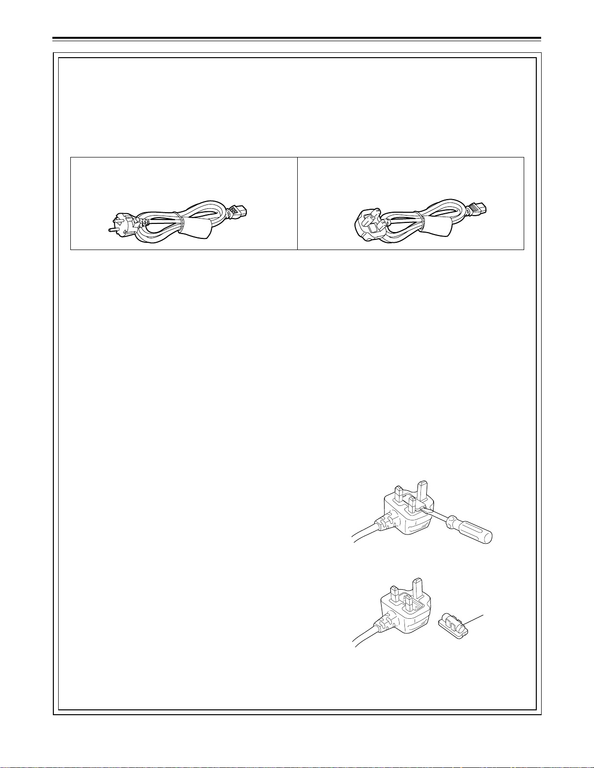
Caution for AC Mains Lead
FOR YOUR SAFETY PLEASE READ THE FOLLOWING TEXT CAREFULLY.
This product is equipped with 2 types of AC mains cable. One is for continental Europe, etc. and the other one is only
for U.K.
Appropriate mains cable must be used in each local area, since the other type of mains cable is not suitable.
FOR CONTINENTAL EUROPE, ETC.
Not to be used in the U.K.
FOR U.K. ONLY
This appliance is supplied with a moulded three pin
mains plug for your safety and convenience.
A 13 amp fuse is fitted in this plug.
Should the fuse need to be replaced please ensure that
the replacement fuse has a rating of 13 amps and that
it is approved by ASTA or BSI to BS1362.
Check for the ASTA mark Ï or the BSI mark Ì on the
body of the fuse.
If the plug contains a removable fuse cover you must ensure that it is refitted when the fuse is replaced.
If you lose the fuse cover the plug must not be used until a replacement cover is obtained.
A replacement fuse cover can be purchased from your
local Panasonic Dealer.
FOR U.K. ONLY
If the plug supplied is not suitable for your socket outlet,
it should be cut off and appropriate one fitted.
As the colours of the wires in the mains lead of this
appliance may not correspond with the coloured markings identifying the terminals in your plug, proceed as
follows:
• The wire which is coloured GREEN-AND-YELLOW
must be connected to the terminal in the plug which is
marked with the letter E or by the Earth symbol Ó or
coloured GREEN or GREEN-AND-YELLOW.
• The wire which is coloured BLUE must be connected
to the terminal in the plug which is marked with the letter N or coloured BLACK.
• The wire which is coloured BROWN must be connected to the terminal in the plug which is marked with
the letter L or coloured RED.
IF THE FITTED MOULDED PLUG IS UNSUIT ABLE FOR
THE SOCKET OUTLET IN YOUR HOME THEN THE
FUSE SHOULD BE REMOVED AND THE PLUG CUT
OFF AND DISPOSED OF SAFELY. THERE IS A DANGER OF SEVERE ELECTRICAL
SHOCK IF THE CUT OFF PLUG IS INSERTED INTO
ANY 13 AMP SOCKET.
If a new plug is to be fitted please observe the wiring
code as shown below.
If in any doubt please consult a qualified electrician.
WARNING: THIS APPLIANCE MUST BE EARTHED.
IMPORTANT: The wires in this mains lead are coloured
in accordance with the following code:
Green-and-Yellow: Earth
Blue: Neutral
Brown: Live
How to replace the fuse
1. Open the fuse compartment with a screwdriver.
2. Replace the fuse.
Fuse
– 2 –
Page 3
For your safety
∫ THIS APPARATUS MUST BE EARTHED
To ensure safe operation the three-pin plug must be
inserted only into a standard three-pin power point
which is effectively earthed through the normal household wiring.
Extension cords used with the equipment must be
three-core and be correctly wired to provide connection to earth. Wrongly wired extension cords are a
major cause of fatalities.
The fact that the equipment operates satisfactorily
does not imply that the power point is earthed and that
the installation is completely safe. For your safety, if in
any doubt about the effective earthing of the power
point, consult a qualified electrician.
∫ DO NOT REMOVE PANEL COVER BY UNSCREW-
ING
To reduce the risk of electr ic shock, do not remove
cover. No user serviceable parts inside.
WARNING:
TO REDUCE THE RISK OF FIRE OR SHOCK
HAZARD, KEEP THIS EQUIPMENT AWAY FROM
ALL LIQUIDS-USE AND STORE ONLY IN LOCATIONS WHICH ARE NOT EXPOSED TO THE
RISK OF DRIPPING OR SPLASHING LIQUIDS,
AND DO NOT PLACE ANY LIQUID CONTAINERS ON TOP OF THE EQUIPMENT.
CAUTION:
TO REDUCE THE RISK OF FIRE OR SHOCK
HAZARD, AND ANNOYING INTERFERENCE,
USE THE RECOMMENDED ACCESSOIRES
ONLY.
CAUTION:
TO REDUCE THE RISK OF FIRE OR SHOCK
HAZARD, REFER MOUNTING OF THE OPTIONAL BOARD TO AUTHORISEDSERVICE
PERSONNEL.
CAUTION:
Do not install or place this unit in a bookcase, built in
cabinet or in another confined space in order to keep
well ventilated condition. Ensure that curtains and any
other materials do not obstruct the ventilation condition
to prevent risk of electr ic shock or fire hazard due to
overheating.
CAUTION
TO REDUCE THE RISK OF FIRE OR SHOCK
HAZARD, REFER CHANGE OF THE SWITCH
SETTING INSIDE THE UNIT TO AUTHORIZED
SERVICE PERSONNEL.
is the safety information.
IMPORTANT
“Unauthorized recording of copyright television
programmes, video tapes and other materials may
infringe the right of copyright owners and be contrary to copyright law.”
■ Do not insert fingers or any objects into the video
cassette holder.
■ Avoid operating or leaving the unit near strong
magnetic fields. Be especially careful of large audio
speakers.
■ Avoid operating or storing the unit in an excessively
hot, cold, or damp environment as this may result in
damage both to the recorder and to the tape.
■ Do not spray any cleaner or wax directly on the unit.
■ If the unit is not going to be used for a length of time,
protect it from dirt and dust.
■ Do not leave a cassette in the recorder when not in
use.
■ Do not block the ventilation slots of the unit.
CAUTION:
Even when the Power Switch is in the OFF
position, a small current flows the filter circuit.
Operating precaution
Operation near any appliance which generates strong
magnetic fields may give rise to noise in the video and audio singals. If this should be the case, deal with the situation by, for instance, moving the source of the magnetic
fields away from the unit before operation.
■ Use this unit horizontally and do not place anything on
the top panel.
■ Cassette tape can be used only for one-side, one
direction recording. Two-way or two-track recordings
cannot be made.
Cassette tape can be used for either Colour or Black &
■
White recording.
■ Do not attempt to disassemble the recorder.
There are no user serviceable parts inside.
■ If any liquid spills inside the recorder, have the recorder
examined for possib le damage.
■ Refer any needed servicing to authorized service
personnel.
– 3 –
Page 4

Contents
For your safety ...........................................................2
General and Features ...............................................5
Controls and their functions ......................................7
Front panel ..............................................................7
•
Connector area .....................................................16
•
Operations using the front panel bottom controls ....19
Operations using the front panel top controls ..........22
Connections .............................................................26
Tapes .......................................................................27
Switching on the power/inserting the cassette .........28
STOP/STAND BY mode ..........................................29
Recording ................................................................30
Playback ..................................................................31
Jog/shuttle ...............................................................32
Manual editing .........................................................33
Preroll ......................................................................34
Automatic editing (deck to deck) .............................35
Switch settings and adjustments ...........................36
•
Selecting the editing mode ....................................37
•
Entering the edit points .........................................38
•
Checking the edit points ........................................39
•
Modifying the edit points .......................................40
•
Preview .................................................................41
•
Executing automatic editing ..................................42
•
Review ..................................................................43
•
Audio split editing ....................................................44
Expansion mode execution using the MODE/SEL
button .....................................................................46
MULTI CUE function ................................................47
IC CARD function.....................................................53
Variable memory function.........................................57
ERROR LOG function ..............................................58
Setup (default settings) ...........................................60
Setup menus ............................................................61
SYSTEM menu .....................................................65
•
USER menu ...........................................................68
•
BASIC menu ......................................................68
•
OPERATION menu ............................................72
•
INTERFACE menu .............................................76
•
EDIT menu .........................................................78
•
TAPE PROTECT menu ......................................81
•
TIME CODE menu .............................................82
•
VIDEO menu ......................................................84
•
AUDIO menu ......................................................89
•
MENU menu .......................................................96
•
Time code/user bit ...................................................97
Recording internal/external time codes ...................98
Reproducing the time code/user bit ........................99
Superimpose screen .............................................100
Audio recording channel and monitor
output selection ....................................................101
Rack mounting ......................................................102
Video head cleaning ..............................................103
Condensation ........................................................103
Error messages .....................................................104
Table of AUTO OFF Error messages ....................106
RS-232C interface .................................................108
Connector signals .................................................115
Printed circuit board ..............................................117
Specifications ........................................................118
Before operating this unit, check that all of its accessories are present and accounted for.
Power cord....1 pc
Options
AJ-MA75P Rack mounting adapter
•
AJ-UDC150AP HD-SD format converter
•
– 4 –
Page 5

General and Features
This unit is a DVCPRO HD format HD digital video cassette recorder which is designed to
use 1/4-inch wide compact cassette tapes.
It is a studio-use digital VTR which can record, play back and edit HD signals (1080i, 59.94
Hz/60 Hz), and can play back tapes recorded using the existing DVCPRO (25 Mbps/50
Mbps) format. Use of the HD-SD conversion facility of the optional format converter enables
interfacing with existing SD systems and development into HD systems. This VTR with its
high picture quality uses high-efficiency digital compression technology to reduce by a
significant margin the degree of deterioration in the sound and picture quality which
accompanies dubbing.
The unit features a compact 4U size and lightweight design to make it easier to carry around.
It can also be easily installed in a 19-inch rack.
The settings for the unit’s setup are performed interactively while viewing the display tube at
the top front of the unit or the screen menus shown on a TV monitor. Both assemble and
insert editing facilities are provided as editing functions.
Features
Compact size and light weight
This is a 4U digital VTR. Using the rack-mounting adapters (optional accessory: AJ-MA75P),
it can also be easily housed in a 19-inch rack.
Up to 46 minutes of recording
The L-size cassettes (max. 46 minutes) are used for recording. The tape is 1/4-inch in width,
which makes for a compact design.
High picture quality
The unit’s high picture quality is achieved by 4:2:2 HD component signal recording using a
recording rate (100 Mbps) which is 4 times higher than that of the existing DVCPRO format.
1080i/720p, 59.94 Hz/60 Hz signal switching
By a process of automatic switching to match the video input signals, each type of signal can
be recorded and played back.
SDI interface
The unit comes with an HD serial digital interface as a standard accessory.
Compatibility with DVCPRO
The unit can play back tapes which have been recorded using the existing DVCPRO (25
Mbps/50 Mbps) format.
Furthermore, consumer-use DV tapes (SP) can also be played back on the unit.
Digital slow motion/dial jog
Clear playback at speeds of -1× through to +1× are made possible with Panasonic’s own
digital-slow technology.
<Note>
Some noise may occur during slow playback (using the external controller) at speeds almost
exactly +1× or -1×.
Search speed
Search speed enables the tape to be played back with colour images at a speed of up to 50
times the forward and reverse direction.
– 5 –
Page 6

General and Features
Features
(continued)
Time codes
This unit comes with a built-in time code generator (TCG)/time code reader (TCR). In
addition to the internal time code, an external time code can also be recorded as the LTC on
the unit’s tape.
Multi-functional interfaces
Serial digital input and output connector
•
The unit features a HD component serial interface input/output connector to enable HD
component video signals and 8-channel digital audio signals to be interfaced using just the
one BNC connector. (SMPTE292M/BTA S-004)
It is also possible to output SD component serial signals provided that the HD-SD format
converter board (optional accessory) is installed. (SMPTE259M-C, 272M, 294M)
Analogue video output connector
•
Composite output connectors are provided as a standard feature. They output composite
signals during DVCPRO reciprocal playback, DV playback or down-conversion. At all other
times, they output the black burst signal.
AES/EBU audio input/output connectors
•
Digital audio input/output connectors for 8 channels are featured as a standard accessory.
9-pin RS-422A and RS-232C remote control connectors
•
In addition to the standard 9-pin serial remote (RS-422A) control connector, the unit is
equipped with RS-232C and 50-pin parallel remote control connectors.
The RS-422A facility enables parallel operation if a loop connection has been performed
between the unit and another VTR.
8-channel high-sound-quality digital audio
The 8-channel PCM audio allows for not only independent editing and mixing on all eight
channels. One channel is provided for the analogue CUE track.
Menu-driven setup
The setup settings, which are conducted prior to operating the unit are performed while
viewing the setup menus either on the unit’s display or a TV monitor.
– 6 –
Page 7
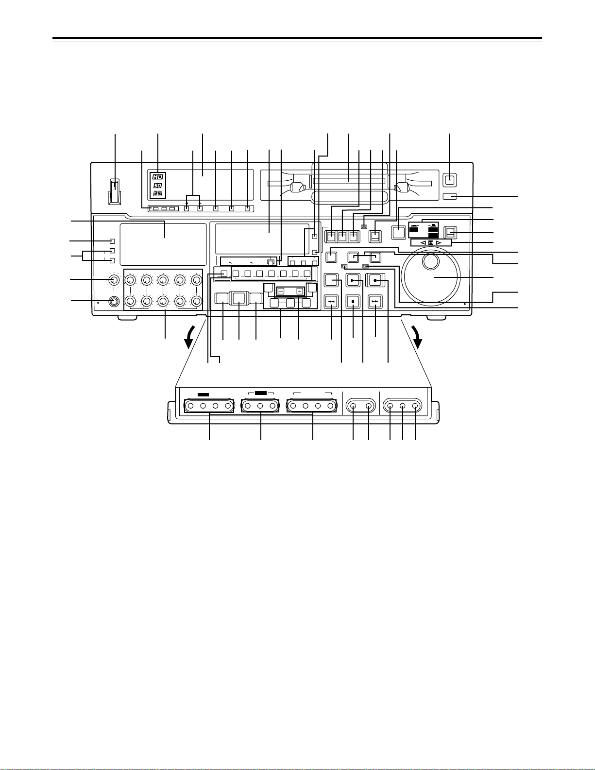
Controls and their functions
Front panel
[
`
_
^
]
1
4
ON
OFF
POWER
METER
FULL/FINE
L
MONITOR SELECT
R
LEVEL
CH 1/5 CH 2/6 CH 3/7 CH 4/8 CUE
HEADPHONES
PULL
OPEN
23
6
REC
PB
V
STATUS
78
AUDIO CH SELECT
CH
1
CH
ASMBL
VIDEO
1
2 3 4 5 6 7 8
MULTICUE
PREVIEW
AUTO EDIT
REVIEW
R
S
W
PROG
SAVE/
MENU
EXIT
5
CH CONDITION ENTER ESCAPE SHIFT
PULL FOR VARIABLE
\
SET UP
X
Z
4
CH 5CH
8
CH1/5 CH2/8 CH3/7 CH4/8 CUE TC
INSERT
A
IN
PREROLL
Q
STATUS
123
IN
T
TRIM
SET OUT
Y
Caution: Do not insert S-cassette without adapter
RESET
TC/CTL
TC SET
SHIFT ADJ
START
A
OUT
U
PROG MENU
1234
H
I
K
J
EJECT
F
9:
G
M-cassette / ADAPTER
L
TC INTTCTAPE
UB
EXT EE
STAND BY
EDIT PLAY
REW STOP
@
A
MODE
CONTROL
PLAYER
RECORDER
SERVO
>
<
MODE/SEL EXIT
REMOTE
LOCAL
REC INHIBIT
REC
FF
?
=
MENU SET DIAG
PUSH
JOG SHTL
SLOW
REV FWD
PULL
OPEN
M
N
O
P
;
D
E
C
B
abc
g h
d
ef
– 7 –
Page 8

Controls and their functions
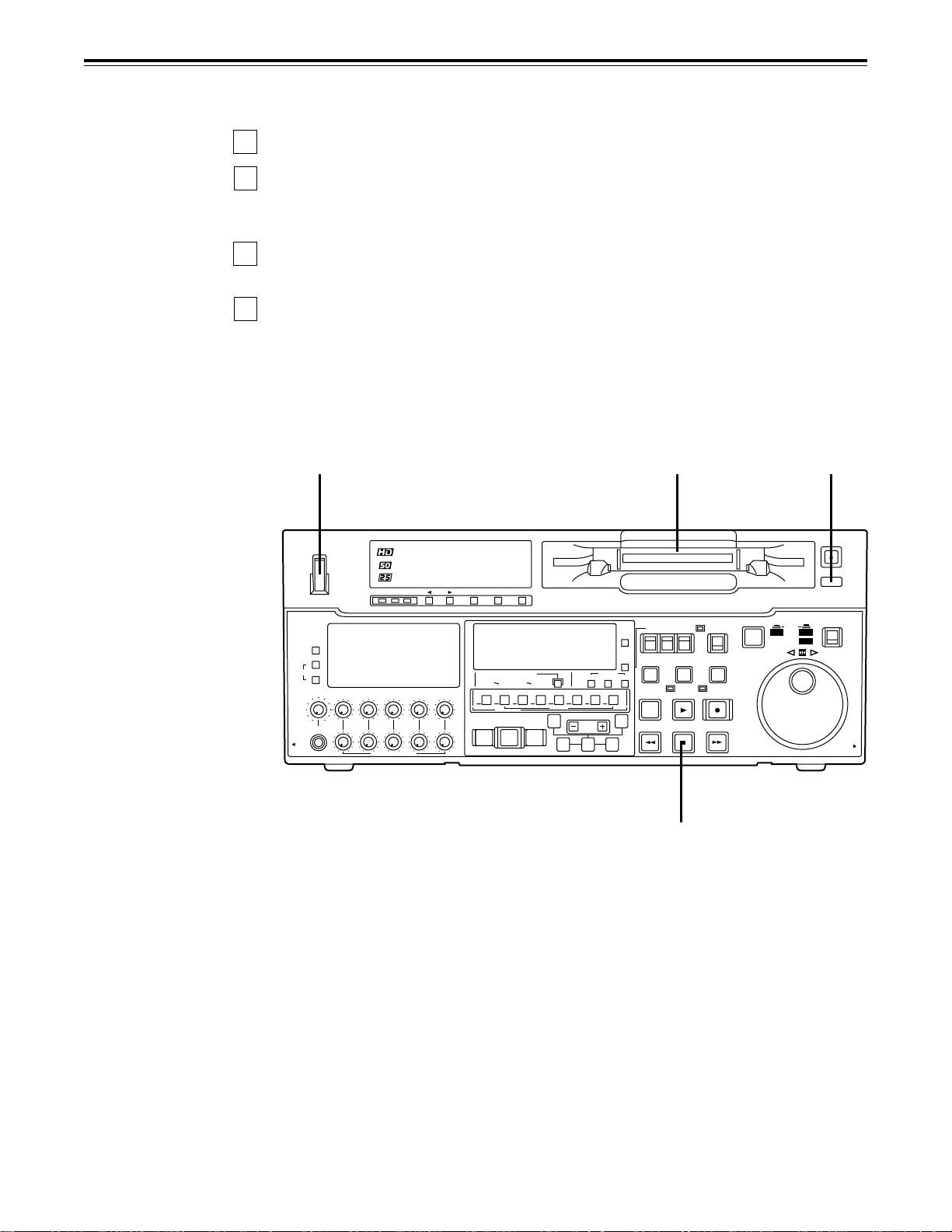
<Front Panel Top Section>
1 POWER switch
2 TV system/format displays
This shows the format during playback.
HD: This indicates that the tape is recorded or played back in the DVCPRO HD format.
50 M: This indicates that the tape is played back in the DVCPRO (50 Mbps) format.
25 M: This indicates that the tape is played back in the DV or DVCAM mode of the
DVCPRO (25 Mbps) format.
33
3 VTR status display area
33
The VTR’s statuses, programmable menus and setup menus appear in this display area.
<Status display>
This indicates the VTR statuses (format, field frequency, video/audio inputs, time code,
etc.) which have been defined by the user on the front sub-panel.
<Programmable menu display>
The setup menus which have been defined by the user are displayed on the front subpanel. Settings can be changed using the 5, 6, 7 and 8 buttons.
<Setup menu display>
The setup menus are displayed using the MENU d button.
44
4 Channel condition lamps
44
One of these lamps lights in accordance with the error rate status. (Green→Amber→Red)
Green: This lights when the error rates for the video and audio playback signals are both
acceptable.
Amber: This lights when the error rate for the video or audio playback signals has
deteriorated.
The playback picture will remain normal even when this lamp lights.
Red: This lights when the video or audio signals are subject to rectification or
interpolation.
55
5 Scroll buttons
55
These are used for left and right scrolling when the status is displayed in the VTR status
display area.
They are used for up and down scrolling when the programmable menu is displayed in the
VTR status display area.
66
6 ENTER button
66
Press this to enter the menu items or the settings when the programmable menu is
displayed.
7 7
7 ESCAPE button
7 7
Press this to ignore or cancel the settings when the programmable menu is displayed.
88
8 SHIFT button
88
The values of programmable menu settings can be changed at high speed by pressing the
scroll buttons while holding down the SHIFT button.
9 Cassette insertion slot
::
: EJECT button
::
When this is pressed, the tape is unloaded and several seconds later the cassette is
automatically ejected. When the counter display indicates “CTL”, the display is reset.
; AUTO OFF lamp
This lights when trouble has arisen in the deck’s operation.
– 8 –
Page 9

Controls and their functions
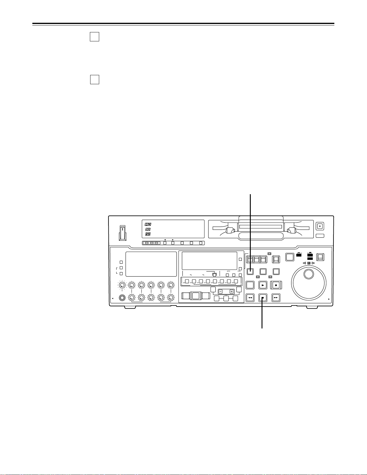
<Front Panel Centre Section>
<<
< PLAY button
<<
Playback commences when this button is pressed.
Recording commences when the button is pressed together with the REC button; manual
editing commences when it is pressed together with the EDIT button during playback.
However, manual editing will not be initiated if the servo is not locked.
Pressing only the PLAY button during manual editing will cut out the editing and establish
the playback mode.
==
= REC button
==
Recording commences when this button is pressed together with the PLAY button.
When it is pressed during playback, search*
and audio signals can be monitored for as long as it is kept depressed.
When it is pressed in the stop mode, EE mode images and sound can be monitored.
When the STOP button is pressed, the original picture and sound are restored.
>>
> STOP button
>>
When this is pressed, the tape stops travelling, and if the TAPE/EE selector switch is at
TAPE, still pictures can be monitored.
The drum continues to rotate even in the stop mode, and the tape remains in close contact
with the drum.
If the stop mode continues for more than a certain period of time, the unit automatically
switches to the standby OFF mode in order to protect the tape.
The stop mode is established immediately after a cassette has been inserted into the unit.
??
? FF button*
??
The tape is fast forwarded when this is pressed.
@@
@ REW button*
@@
The tape is rewound when this is pressed.
2)
2)
1)
, fast forward or rewind, EE mode images
AA
A EDIT button
AA
For manual editing, press both this button and the PLAY button together during playback.
When the button is pressed in the stop mode, the input mode signals selected by the
ASMBL or INSERT button can be monitored in the EE mode.
The original picture and sound are restored when the STOP button is pressed.
When the button is pressed during playback, search*1), fast forward or rewind, the input
signals of the mode selected by the ASMBL or INSERT button can be monitored in the EE
mode for as long as the button is held down.
BB
B SERVO lamp
BB
This lights when the drum servo and capstan servo have locked.
CC
C REC INHIBIT lamp
CC
In the following situations, this lamp lights up to indicate that recording and editing cannot be
performed.
(Related setup menu items No.022, No.023, No.113, No.114, No.117 and No.118)
1. When 1 (ON) has been selected as the setup menu item No.113 (REC INH) setting
2. When the cassette has been set to the accidental erasure prevention mode
3. When MANUAL has been selected as the setup menu No.022 (PB FORMAT), 50M/
25M/50Mp/DV/DVCAM has been selected as the menu No.023 (FORMAT SEL), ON
has been selected as the menu No.118 (SD MODE INH), and the tape has been
inserted
4. When AUTO has been selected as the setup menu No.022 (PB FORMAT), ON has
been selected as the menu No.118 (SD MODE INH), and a DVCPRO, DVCPRO50,
DVCPRO50P, DV or DVCAM tape has been inserted.
5. When ON has been selected as the setup menu No.117 (M CASSTT INH) and the M
cassette tape has been inserted
1)
No guarantees are given for the audio playback sound in the search mode.
*
2)
The FF/REW speed can be selected on the setup menu No. 102 (FF. REW MAX), and it is
*
set to the same speed.
– 9 –
Page 10

Controls and their functions
<Front Panel Centre Section>
DD
D STAND BY button
DD
When this is pressed, the same tension as in the regular stop mode is applied to the tape,
and while the head drum continues to rotate, the button’s lamp lights to indicate that the
standby ON mode is established.
In the standby OFF mode, the half-loading mode is established.
When this button is pressed in the stop mode, the standby OFF mode is established, the
half-loading mode is established. The lamp in the button now goes off. When the unit
remains in the stop mode for longer than a predetermined period, the standby OFF mode
is automatically established in order to protect the tape.
When this button or the STOP button is pressed in the standby OFF mode, the standby
ON mode is established.
When a button other than the STOP button is pressed, the mode corresponding to the
button pressed is established.
On-screen settings are available for the transfer time to the standby OFF mode.
EE
E PLAYER/RECORDER buttons
EE
These buttons are operated when editing operations are conducted using the unit as the
recorder and a VTR equipped with an RS-422A serial interface remote control connector
(9 pins). Neither button functions when the unit is used on its own.
PLAYER button: When this button is pressed, its lamp lights, and the player connected
to the unit can be operated by remote control. The unit’s editing and
tape transport buttons now control the player’s functions.
RECORDER button:When this button is pressed, its lamp lights, and the editing and tape
transport buttons control the recorder’s (= the unit’s) functions.
Both lamps light, and the recorder functions as the master unit for Parallel Run operations
if the PLAYER or RECORDER button is pressed while “ENA” has been selected for setup
menu No. 200 (PARA RUN). [However, external control can no longer be exercised from
the REMOTE connector (9-pin) when this setting has been made.]
FF
F TC/CTL switch
FF
By pressing this switch, what appears on the counter display is changed between TC and
CTL.
When TC is selected, either the TC or UB value is displayed depending on the position
selected by the TC/UB switch.
GG
G TC/UB switch
GG
This selector switch determines whether the value of TC or UB appears on the counter
display when the TC/CTL switch has been set to TC.
HH
H INT/EXT switch
HH
INT: For using the built-in time code generator.
EXT: At this position, the external time code which is input from the time code input
connector is used.
II
I TAPE/EE switch
II
<In the stop mode>
TAPE: For outputting the signals played back from the tape.
EE: For outputting the input signals selected by the setup menus No. 600 (VIDEO IN
SEL) and No. 700 (AUDIO IN SEL).
<In the editing*/recording mode>
TAPE: For outputting the simultaneous playback signals.
EE: For outputting the input signals selected by the setup menus No. 600 (VIDEO IN
SEL) and No. 700 (AUDIO IN SEL).
* The SETUP menu No. 302 (CONFI EDIT) setting is required.
– 10 –
Page 11

Controls and their functions
<Front Panel Centre Section>
JJ
J REMOTE/LOCAL switch
JJ
This switch is set when the unit is to be controlled from an external source using the
REMOTE connector, RS-232C connector or parallel connector.
REMOTE: Set to this position when controlling the unit by a device connected using the
9-pin REMOTE connector or RS-232C/parallel connector.
LOCAL: Set to this position when controlling the unit using the controls on its own
operation panel.
KK
K REMOTE lamp
KK
This lights when the REMOTE/LOCAL switch has been set to the REMOTE position.
LL
L Search button
LL
This button is pressed to establish the search mode.
When the search dial is set to the shuttle mode and turned to a particular position, and this
button is pressed, playback commences at the speed set by the search dial.
MM
M JOG/SHTL/SLOW lamps
MM
These indicate the present status of the search dial and SHTL/SLOW switch.
JOG: This lights when the unit is in the JOG mode.
SHTL: This lights when the unit is in the SHTL mode.
SLOW: This lights when the unit is in the SLOW mode.
NN
N SHTL/SLOW switch
NN
This selector switch is set when the search dial is used for SHTL or SLOW applications.
OO
O REV/STILL/FWD lamps
OO
One of these lamps lights depending on the operation of the search dial.
REV: This lights when the dial is turned counterclockwise and the tape travels in the
REV direction provided that the lamp in the search button has lit.
STILL: This lights in the JOG mode while the dial is kept stationary, and the tape stops
travelling provided that the lamp in the search button has lit.
It lights in the SHTL mode provided that the dial is at the STILL position.
FWD: This lights when the dial is turned clockwise, and the tape travels in the FWD
direction provided that the lamp in the search button has lit.
PP
P Search dial
PP
This is used to search for the edit points.
Each time it is pressed, the mode is alternately set to shuttle or jog, and one of the JOG,
SHTL and SLOW lamps lights. When the power has been turned on, the dial will not
function until it has first returned to the STILL position.
Shuttle mode: When the dial is turned and stopped at a particular position while the
SHTL/SLOW switch is at SHTL, the tape can be played back at the speed
corresponding to the dial’s rotary angle position. A still picture appears at
the dial’s centre position.
Slow mode: When the dial is turned all the way counterclockwise with the SHTL/SLOW
switch at SLOW, the tape speed is set to –4.1× normal speed, when it is
set to the centre position, a still picture is produced, and when it is turned
all the way clockwise, the tape speed is set to +4.1× normal speed. The
speed for SLOW can be set using setup menu No. 308 (VAR FWD MAX)
and No. 309 (VAR REV MAX).
Jog mode: The dial clickstops are cleared, and the tape is played back at the speed
(–1 × to +1× normal speed) corresponding to the speed at which the dial is
turned.
– 11 –
Page 12

Controls and their functions
<Front Panel Centre Section>
QQ
Q PREROLL button
QQ
This is used for feeding and cueing the tape for manual editing.
When it is pressed, the tape travels to the preroll point where it stops.
The preroll time can be set on the setup menu No. 000 (P-ROLL TIME).
When this button is pressed together with the IN or OUT button, the tape can be cued to
the IN or OUT point entered.
When the AUTO ENTRY on the setup menu No. 305 is set to “ENA”, IN point has been
entered at the point where the PREROLL button is pressed even if the IN point has not
been entered.
RR
R AUTO EDIT button
RR
Automatic editing is executed when this is pressed after an edit point has been entered.
When the AUTO EDIT button is pressed though the IN point has not been entered,
automatic editing is executed using the point at which the button was pressed as the IN
point.
SS
S PREVIEW/REVIEW buttons
SS
PREVIEW: When this is pressed after an edit point has been entered, the tape travels,
editing is not performed, and the preview can be activated on the screen
connected to the recorder.
If it is pressed when the IN point has not been entered, the point at which the
button was pressed is entered as the IN point, and preview is executed
accordingly.
REVIEW: If this is pressed after a block has been edited, the now edited block can be
played back and monitored on the screen connected to the recorder.
TT
T IN (A IN)/SET/OUT (A OUT) buttons
TT
When IN (A IN) or OUT (A OUT) button is pressed together with the SET button, the IN (A
IN) or OUT (A OUT) point is entered.
A IN and A OUT are used during audio split editing to enter an audio IN or OUT point that
differs from the video In or OUT point.
While an IN (A IN) or OUT (A OUT) point is selected, the IN (A IN) or OUT (A OUT) button
corresponding to the point entered lights. When this button is pressed after a point has
been entered, the IN (A IN) /OUT (A OUT) point value appears on the counter display.
When the IN (A IN) or OUT (A OUT) button is pressed together with the RESET button, the
IN (A IN) or OUT (A OUT) point is cleared.
UU
U TRIM buttons
UU
These buttons are used to trim IN or OUT point finely.
When the “+” or “–” button is pressed while the IN or OUT button is held down, the entered
edit point can be trimmed in 1-frame increments. When the “+” button is pressed, the tape
is advanced by one frame; when the “–” button is pressed, it is rewound by one frame.
VV
V ASMBL button
VV
This is pressed for assemble editing.
The button is self-illuminating, and it is set ON (lamp lights) when it is pressed once and
OFF (lamp goes off) when it is pressed again.
WW
W INSERT buttons
WW
Press one of these seven buttons to select the input signals to be edited during insert
editing.
The buttons are self-illuminating, and they are set ON (lamp lights) when they are pressed
once and OFF (lamp goes off) when they are pressed again.
The audio channels (CH1 to CH8) are allocated to CH1-4 or CH5-8 using the AUDIO CH
SELECT button Z.
– 12 –
Page 13

Controls and their functions
<Front Panel Centre Section>
XX
X Counter display area
XX
The TC and CTL count values, UB and messages are displayed in this area.
Cassette inserted display lamp:
This lamp lights when a cassette has been inserted into the unit.
DVCPRO format (25 Mbps/50 Mbps) cassette play display lamp:
This lights when a cassette which was recorded using the DVCPRO (25 Mbps/50 Mbps)
format is being played back.
SCH lamp:
This lights when the SCH phase of the SD REF signal is within a fixed range.
CF lamp:
This lights when the colour framing is locked.
TC/UB lamp:
This flashes when the TC or UB information cannot be read during tape playback; it
remains lit while the information is being read properly.
YY
Y Time code buttons
YY
These are used to set the TC or UB value.
SHIFT: When setting the TC or UB value, first press this button to stop the data running.
Change the digit now flashing on the display.
Each time the button is pressed, the flashing moves to the right by one digit, and
when it reaches the right-most digit, it returns to the left-most digit.
When it is kept depressed, the flashing moves consecutively.
ADJ: This is used to change the numeral of the digit now flashing on the display.
When the button is pressed once, the number is incremented by 1, and when it is
kept depressed, the number is incremented consecutively.
START: This enters the data which has been changed by the SHIFT and ADJ buttons.
Also, Pressing this button when the TC or UB value are not set enables the TCG
or UBG setting values to be confirmed.
RESET: When this button is pressed in the CTL mode, the display is reset to
“00:00:00:00”. In the CTL mode, the entered edit points are cleared.
In the TC/UB mode, the generator is reset when the button is pressed together
with the SHIFT button.
ZZ
Z Audio channel selector button
ZZ
This button is used to switch the display and control of the CH1-CH4 or CH5-CH8 audio
metre and volume and insert buttons.
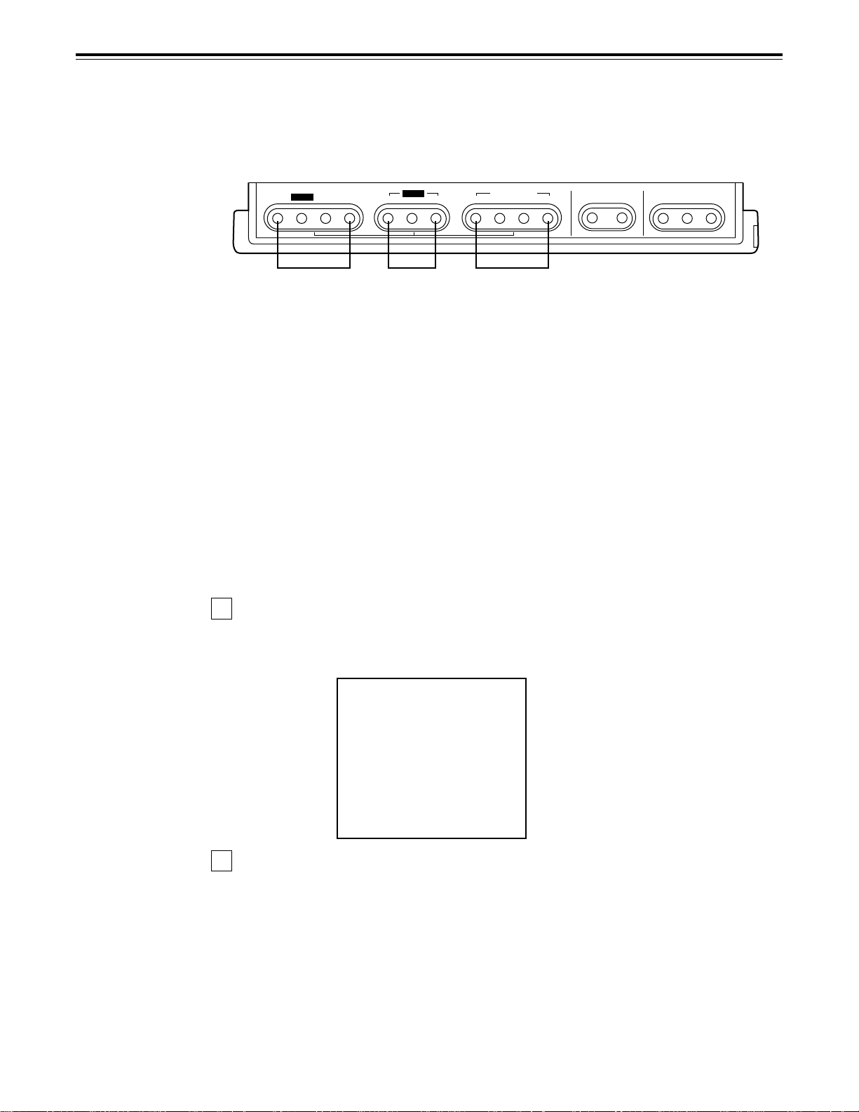
[ [
[ Level metre
[ [
This displays the levels of the PCM audio signals for CH1, CH2, CH3 and CH4 (or for
CH5, CH6, CH7 and CH8) and CUE track signals.
During recording and E-E selection, it displays the levels of the audio input signals; during
playback, it displays the levels of the audio output signals.
\\
\ Audio input/output level controls
\\
These controls are used to adjust the recording and playback levels of the PCM audio
signals (CH1/CH2/CH3/CH4/CH5/CH6/CH7/CH8) and the CUE track signal.
The upper controls are for adjusting the recording levels.
The lower controls are for adjusting the playback levels.
Each control is a “pull for variable” control, meaning that the level can be adjusted only
when the control has been pulled up. The signal levels are set to the unity value (preset
value) when the controls have been pushed down.
Furthermore, when the channels have been switched between CH1-4 and CH5-8 using
the AUDIO CH SELECT button Z, the previous information is retained until the controls
are next operated.
– 13 –
Page 14

Controls and their functions
<Front Panel Centre Section>
]]
] Headphones jack
]]
The sound being recorded, played back or edited can be monitored on stereo headphones
when they are connected to this jack.
^^
^ Volume control
^^
This is used to adjust the headphones volume and the monitor output volume.
Whether the headphones output and monitor output volumes are to be linked or kept
separate can be set on the setup menu No. 713 (MONI OUT). (Note that the headphones
output volume is normally linked.)
When the volumes are kept separate, the monitor output is set to the unity value (preset
value).
__
_ MONITOR SELECT switches
__
These are used to select the audio signals output to the monitor L/R channels.
Each time the “L” button is pressed, the signals output to the monitor L channel are
selected in turn in the following order: CH1, CH2, CH3, CH4, CH5, CH6, CH7, CH8, CUE
and back to CH1.
[However, this switching is disabled when the channel except OFF has been selected for
setup menu No. 734 (MONITOR MIX L).]
Each time the “R” button is pressed, the signals output to the monitor R channel are
selected in turn in the following order: CH1, CH2, CH3, CH4, CH5, CH6, CH7, CH8, CUE
and back to CH1.
[However, this switching is disabled when the channel except OFF has been selected for
setup menu No. 735 (MONITOR MIX R).]
The L or R lamp on the level metre display lights to indicate which signal is now being
selected. (When the unit is set to “AUTO” in No. 745 (MONI CH SEL) on the setup menu,
then the display will change according to the monitor output.)
The lamp flashes if the channels selected by AUDIO CH SELECT do not appear on the
display screen.
``
` METRE (FULL/FINE) selector switch
``
This is used to change the scale display (graduations) of the audio level metres.
FULL mode: Standard scale (from –¶ to 0 dB)
FINE mode: The scale changes every 0.5 dB.
aa
a User assignment switch
aa
This enables the VTR statuses and programmable menus to be registered.
Refer to page 18 for details.
bb
b Status selector switch
bb
This enables the statuses to be registered by the user assignment switch in 3 ways.
Refer to page 18 for details.
cc
c Programmable menu selector switch
cc
This enables the programmable menus to be registered by the user assignment switch in
4 ways.
Refer to page 18 for details.
dd
d MENU button
dd
When this is pressed, the setup menu appears on the TV monitor (when the HD SDI
OUT3, SD SDI OUT3 and VIDEO OUT3 connectors are being used).
The setup menu numbers and items are displayed on the unit’s top front display area.
Press the button again to exit the setup menu settings and return to the original status.
– 14 –
Page 15

Controls and their functions
<Front Panel Bottom Section>
ee
e SET button
ee
When this is pressed, the data which has been set on the setup menu is entered. After
data entry, the setup menu setting mode is exited and the original operating mode is
restored.
ff
f DIAG button
ff
When this is pressed, VTR information is displayed on-screen. When it is pressed again,
the original display is restored.
There are two types of VTR information: “HOURS METER” information and “WARNING”
information. Switching between these types is enabled by pressing the search button.
Indicated on the “HOURS METER” screen are the power-on time, drum rotation time, tape
travel time, loading count and power ON/OFF time, etc.
Indicated on the “WARNING” screen are the warning.
MODE/SEL button
g
This is used to initiate a MULTI CUE operation or other expansion mode operation. For
details, refer to page 47.
h EXIT button
This is used to exit from the MULTI CUE operation or other expansion mode operation and
return to the original mode.
– 15 –
Page 16
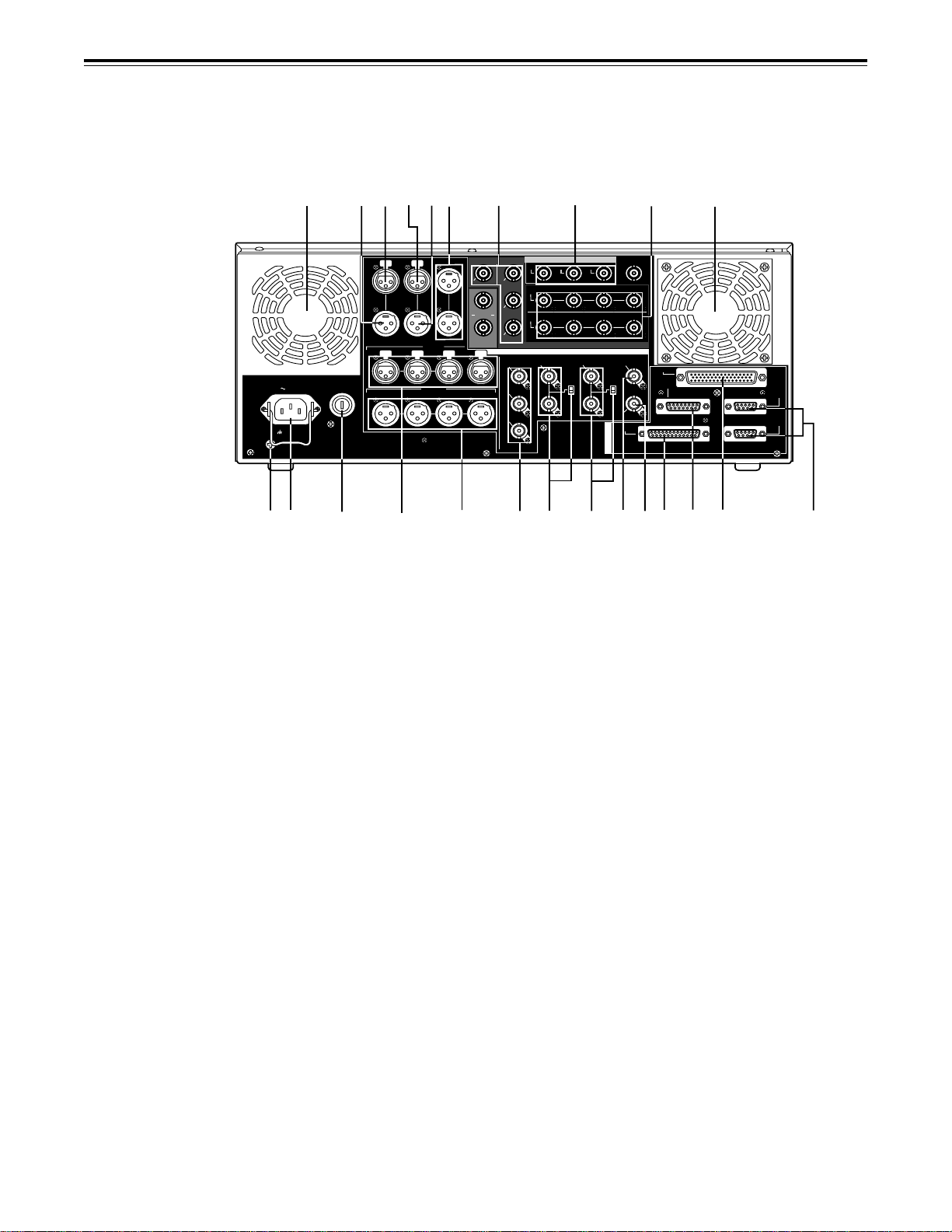
Controls and their functions
Connector area
SIGN
2
GD
OUT 1
AUDIO
IN
AUDIO
OUT
CH1·2
CH1·2
ANALOG
SD REF IN
OUT 2 OUT 3
=
SD SDI
SD SDI
(SUPER)
CH3·4 CH5·6 CH7·8
CH3·4 CH5·6 CH7·8
DIGITAL AUDIO
HD REF IN HD REF OUT
ON
75≠
OFF
@
;
<
HD SDI
OUT 1
IN
OUT 2
(OPTION)
OUT 3
(SUPER)
PUSH
VIDEO OUT
1
2
(WFM)
(SUPER)
3
>? A
4
FUSE 250V T4H
AC IN
L
1
5
6
TC
PUSH
PUSH PUSHPUSH
IN IN L
OUT
CH 1
PUSH PUSH PUSH
CH 1 CH 2 CH 3 CH 4
3
9
8
7
CUE MON
OUT R
AUDIO IN
CH 2 CH 3 CH 4
AUDIO OUT
:
C
OPTION
PARALLEL
ON
ENCODER
REMOTE
75≠
OFF
SD
REF OUT
R
RS-232C
E
M
O
T
E
B
4
EFG
REMOTE
IN/OUT
REMOTE
OUT
D
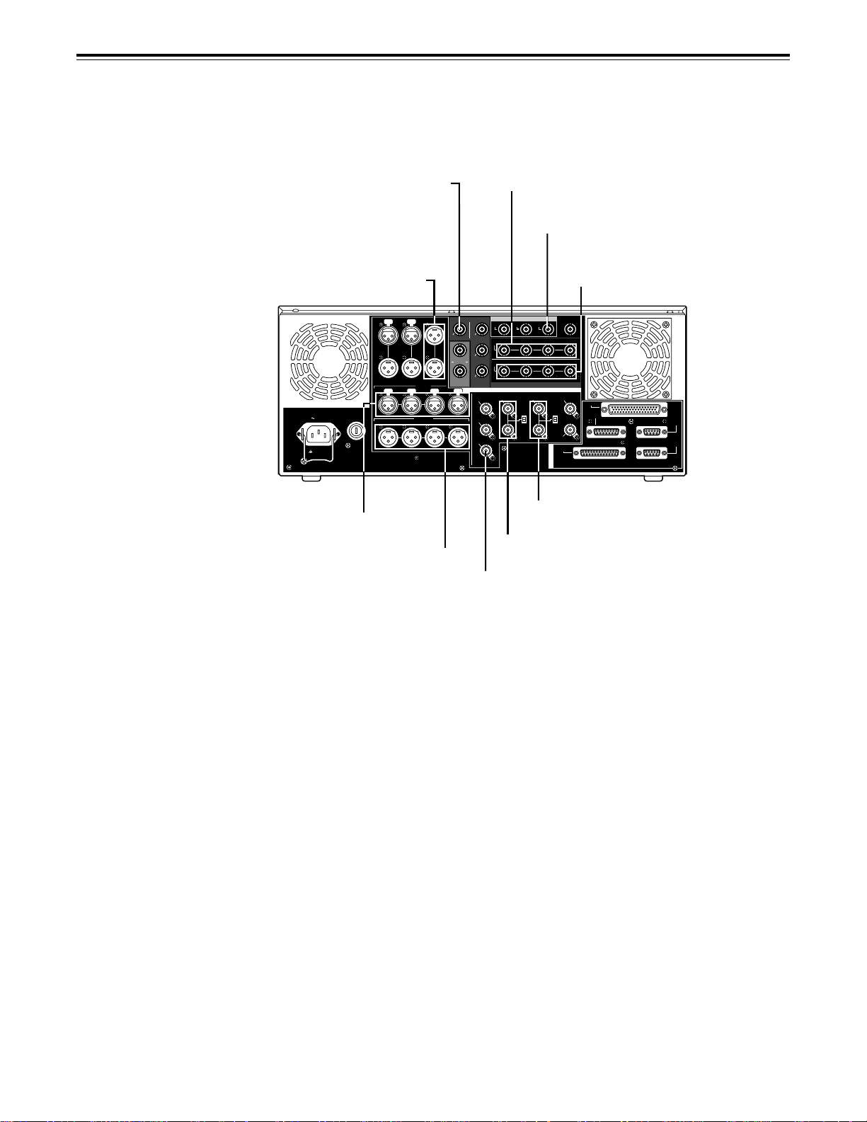
1 Power mains socket
This is for connecting the unit to the power mains socket using the power cord provided.
2 SIGNAL GND terminal
This terminal is connected to the signal ground terminal of the connected unit in order to
reduce noise. It is not connected to ground for safety purposes.
3 Fuse holder
This contains a fuse.
4 Fan motor
This is for cooling the unit.
The W lamp lights when trouble has caused the fan motor to stop. If the unit is still
operated in the warning status, the temperature inside the deck will rise, and when it
exceeds the safety temperature, all the unit’s operations will be shut down.
– 16 –
Page 17

Controls and their functions
<Connector area>
5 TIME CODE IN connector
This is the connector for recording the external time code on the tape.
6 TIME CODE OUT connector
The playback time code is output from this connector during playback.
During recording, the time code generated by the internal time code generator is output.
7 CUE IN connector
The analogue signal to be recorded on the CUE track is supplied to this connector. The
audio signals from a microphone can also be recorded by selecting the –60dB input mode
on the setup menu No. 705 (CUE IN LV).
8 CUE OUT connector
The analogue signal recorded on the CUE track is output from this connector.
9 MONITOR OUT connector
During playback, the playback signals from the CUE track or PCM audio signal CH1, CH2,
CH3, CH4, CH5, CH6, CH7 and CH8 are output from this connector.
: ANALOG AUDIO IN connectors
These are the input connectors for the analogue audio signals (CH1, CH2, CH3, CH4).
; ANALOG AUDIO OUT connectors
These are the output connectors for the analogue audio signals (CH1, CH2, CH3, CH4).
<<
< HD SERIAL DIGITAL COMPONENT AUDIO VIDEO IN/OUT connectors
<<
These are the input and output connectors for the HD digital component audio and video
signals that comply with the SMPTE 292M standard.
The TC, menu or other information is output from the HD SDI OUT3 connector with the
information superimposed onto the signals.
==
= SD SERIAL DIGITAL COMPONENT AUDIO VIDEO OUT connectors
==
These are the output connectors for the digital component audio and video signals that
comply with the SMPTE 259M-C, 272M and 294M standards.
The signals are output during the playback of compatible DVCPRO25M, 50M, DV or
DVCAM format tapes or during down-conversion output (optional accessory).
The TC, menu or other information is output from the SD SDI OUT3 connector with the
information superimposed onto the signals.
>>
> ANALOG COMPOSITE VIDEO OUT connectors
>>
These are the output connectors for the analogue composite video signals.
The signals are output during the playback of compatible DVCPRO25M, 50M, DV or
DVCAM format tapes or during down-conversion output (optional accessory).
Video signals with information superimposed onto them can be output from the VIDEO
OUT3 connector.
Whether information is to be superimposed or not (ON/OFF) is selected by setting the
setup menu No.005 (SUPER) item.
The VIDEO OUT2 connector can also be used as the WFM (waveform) OUT connector.
TC, CTL, VIDEO, RF L/R and ENV L/R are the signals which can be selected on the
menu.
– 17 –
Page 18

Controls and their functions
<Connector area>
??
? SD REF IN connectors and 75-ohm termination switch
??
These are the input connectors for the SD reference video signals.
Input the NTSC signals with colour burst.
To terminate, set the switch to ON.
@@
@ HD REF IN connectors and 75-ohm termination switch
@@
This is the input connectors for the HD reference video signals.
Input tri-level sync signals with positive and negative polarities.
To terminate, set the switch to ON.
A A
A HD REF OUT connector
A A
This is the output connector for the HD reference video signals used for external
synchronization.
It outputs tri-level sync signals with positive and negative polarities.
The field frequency is synchronized with the input signals. (If no signals are input, the
frequency follows the menu setting.)
BB
B SD REF OUT connector
BB
This is the output connector for the NTSC external synchronization signal (black burst
signal).
CC
C DIGITAL AUDIO IN/OUT connector
CC
This I/O connector is for digital audio signals which comply with the AES/EBU standard.
D Remote control connectors
The unit can be controlled from an external source by connecting the unit with another unit
or an external controller.
There are two remote control connectors, one for IN/OUT uses and the other for OUT
uses.
IN/OUT: For connection with an external controller.
For connection with deck-to-deck operation.
OUT: For connection with parallel running operations.
For use in a loop-through configuration.
E ENCODER REMOTE connector
The external encoder/controller is hooked up to this connector when the video output
signal and other settings are to be adjusted from an external source.
F RS-232C connector
G PARALLEL REMOTE connector
This is used when operating the unit from an external source.
– 18 –
Page 19
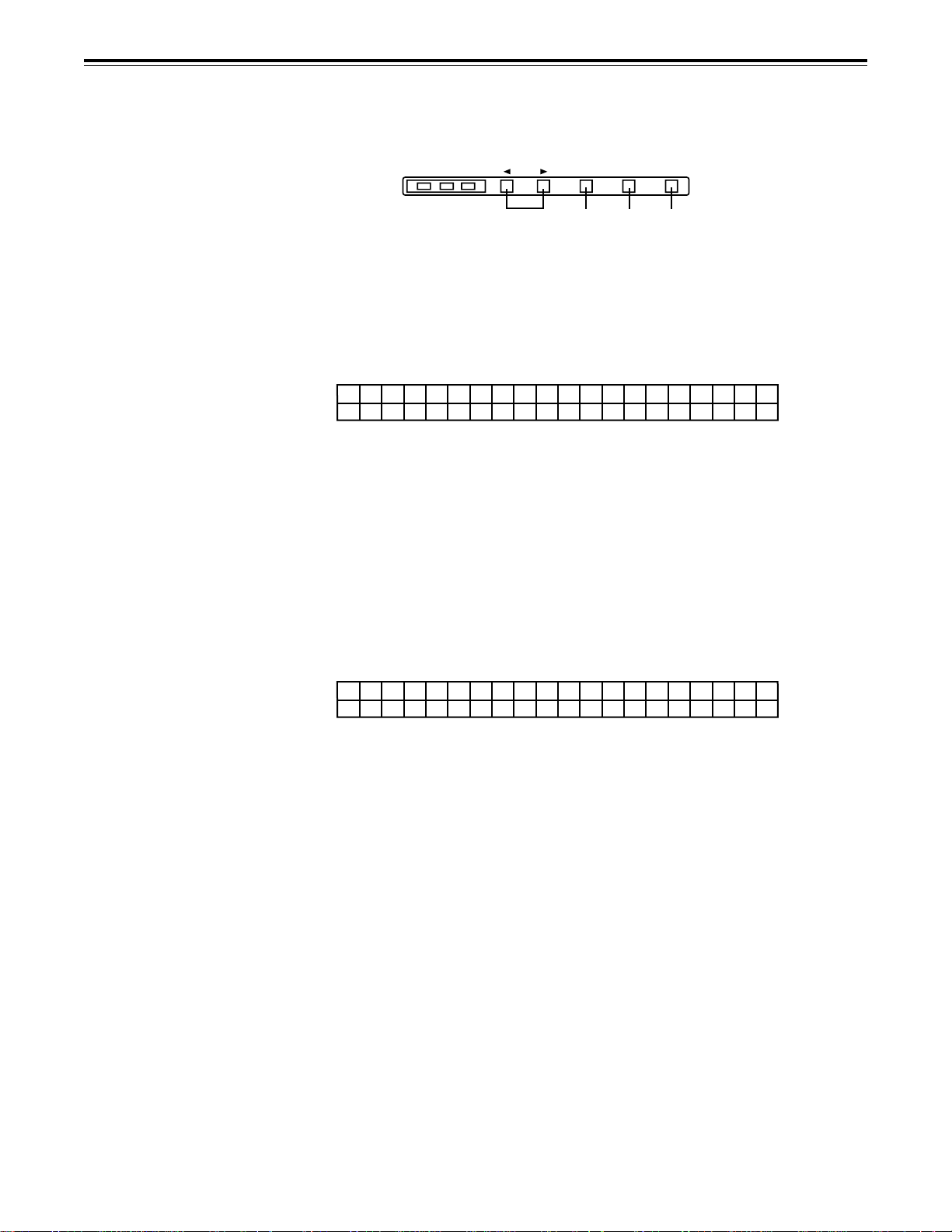
Operations using the front panel bottom controls
The desired status information and setup menu items can registered in the STATUS 1 to 3
buttons b and PROG MENU 1 to 4 buttons c by using the SETUP, STATUS, PROG MENU
and SAVE/EXIT buttons a. Once the information has been registered, it can be indicated on
the VTR status display area 3 by pressing the STATUS 1 to 3 buttons b or PROG MENU 1
to 4 buttons c concerned.
PROG
SET UP
STATUS
MENU
SAVE/
EXIT
a
Items which can be registered
The following items can be registered in the buttons.
STATUS: Up to 9 items including the recording format and playback format can be
•
registered in these buttons. (Refer to the VTR status item table for
descriptions of the items and contents.)
PROG MENU: Up to 9 items from setup menus in the 000 range to 700 range can be
•
registered in these buttons. However, the submenus of setup menu item
No.680 (BLANK LINE) cannot be registered.
Registration method
The items are registered as they are selected by the menu-driven system. Connect the TV
monitor to the VIDEO OUT3 connector in the unit’s connector area and display the
registration menu.
STATUS
123
b
PROG MENU
1234
c
MODE/SEL EXIT
MENU SET DIAG
1
Press the SETUP button.
The message indicating that the registration steps can now be commenced appears on
the TV monitor.
-ASSIGNMENT MODE-
select any key!
MENU :<PROG MENU>
STATUS :<STATUS>
EXIT :<SETUP>
2
Select the button which corresponds to the objective.
PROG MENU buttons:The registration menu for registering the setup menu items in
•
the PROG MENU 1 to 4 buttons is displayed.
STATUS buttons: The registration menu for registering the VTR status
•
information in the STATUS 1 to 3 buttons is displayed.
SETUP buttons: This cancels the registration operation.
•
– 19 –
Page 20

Operations using the front panel bottom controls
3
Turn the search dial and select the item to be registered.
The cursor (¢) on the menu screen now moves.
∫Example of the menu displayed for registering setup menu items
ASSIGN-MENU BASIC
<USER> N0.000 - 1---
¢
000 P-ROLL TIME 1-- 001 LOCAL ENA -2- 002 TAPE TIMER --3 003 REMAIN SEL --- 004 SYNCHRONIZE --- 005 SUPER --- 006 DISPLAY SEL --- 007 CHARA H-POS --- 008 CHARA V-POS ----
∫Example of the menu displayed for registering VTR statuses
ASSIGN-MENU
<STATUS> N0.000 - 1---
¢
000 REC FORMAT 1-- 001 REF OUT -2- 002 PB FLD RATE --3 003 REC FLD RATE --- 004 HD OUT --- 005 SD OUT --- 006 UFC --- END ----
4
When registering setup menu items: At the position of the item to be registered,
select the PROG MENU button (1, 2, 3 or 4) in
which the information is to be registered, and
press it.
When registering VTR statuses: At the position of the item to be registered,
select the STATUS button (1, 2 or 3) in which
the information is to be registered, and press it.
The number of the button corresponding to the button that was pressed is now
displayed. When the same button is pressed again, the button number display is
released.
5
To register more items, repeat steps 3 and 4.
6
Press the SAVE/EXIT button.
The registered information is now saved in the memory. (When more than one item
has been registered, the information will be stored in sequence starting with the lowest
item number.)
To return the registered information to the state prior to registration, press the STOP
button.
– 20 –
Page 21

Operations using the front panel bottom controls
∫ To return the registered information to the factory settings (initial settings), press
the RESET button while the registered menu item is displayed. The following
message will appear.
∫Example of the menu displayed for resetting setup menu items which have been
registered
ASSIGN-MENU INIT SET
select any key!
ALL <PLAY>
MENU1 <MENU1>
MENU2 <MENU2>
MWNU3 <MENU3>
MENU4 <MENU4>
CANCEL <STOP>
PLAY button: Whatever items have been registered in the PROG
MENU 1 to 4 buttons b are reset to the factory
settings.
PROG MENU 1 to 4 buttons: The button which was pressed is returned to the non-
registration status.
CANCEL button: This is for cancelling the reset operation.
∫Example of the operation menu displayed for resetting VTR statuses which have
been registered
ASSIGN-MENU INIT SET
select any key!
ALL <PLAY>
STATUS1 <STATUS1>
STATUS2 <STATUS2>
STATUS3 <STATUS3>
CANCEL <STOP>
PLAY button: Whatever statuses have been registered in the STATUS 1 to 3
buttons c are reset to the factory settings.
STATUS 1 to 3 buttons: The button which was pressed is returned to the non-
registration status.
CANCEL button: This is for cancelling the reset operation.
– 21 –
Page 22
Operations using the front panel top controls
What has been registered in the STATUS 1 to 3 buttons b and PROG MENU 1 to 4 buttons
c located at the bottom of the panel can be called to the VTR status display area 3 by
pressing the button concerned.
The called item can be operated using the buttons shown below.
CH CONDITION ENTER ESCAPE SHIFT
567
8
1-1 VTR status displays
When the power is turned on, the information registered in the STATUS 1 button appears on
the display, and after this point what is displayed can be switched by pressing the STATUS 1
to 3 buttons b.
[Example of status display]
RlE0C8F0RiM RIENFTO5U9T...........
.
≥
Each item consists of 6 characters. Three items can be displayed at the same time.
The names of the items appear on the first line, and their statuses on the second line.
≥
When the number of registered items is 4 or more, press the SCROLL buttons 5 to scroll
the display to the left or right.
≥
When the number of registered items is less than 3, “.....” appears in the sections where
items have not been registered.
2-1 Registered menu item displays
The registered setup menu items are displayed by pressing the PROG MENU 1 to 4 buttons
c.
[Example of registered menu item display]
¢ PL_ORCOALLL
ETNIA
ME
ST&5EsJ
Digit 1: Cursor (¢) for selecting items/mark (!) indicating that a setting is being
changed
Digits 2 to 13: Name of the menu item (12-character display)
Digit 14: Cursor for selecting item
Digits 15 to 20: Setting (6-character display)
≥
Two registered menu items can be displayed at the same time.
≥
When the number of registered items is 3 or more, press the SCROLL buttons 5 to scroll
the display up or down.
≥
The data in the currently selected user file (USER1 to USER5) is reflected in the settings.
– 22 –
Page 23

Operations using the front panel top controls
2-2 How to change a registered menu setting
Selecting the menu item: Press the SCROLL buttons 5 to move the item
selection cursor (¢) up or down, and select the menu
item.
Transferring to the change mode: Press the ENTER button 6 to transfer to the setting
change mode. Whether operation has transferred to
the change mode is confirmed by the movement of the
item selection marker to digit 14.
Changing the setting: Press the scroll buttons 5 to change the setting.
When a change has been made to the current setting,
the mark (!) indicating that a setting is being changed
appears at digit 1 to indicate the status.
!PL_ORCOALLL
ETNIA
≥
If the item allows for a wide range of variation in its
setting, continue to press one of the SCROLL buttons
5 while holding down the SHIFT button 8, and the
setting can be incremented or decremented at a
higher speed.
Entering the setting: Press the ENTER button 6 to enter the setting change
and return to the menu selection status.
Cancelling the change: Press the ESCAPE button 7 to cancel the setting
change and return to the menu selection status.
<Note>
When the user file now selected is one of USER2~USER5, the setup menu No. 403 (MENU LOCK)
selection is 1 (lock setting), you cannot go to the set-value change mode.
ME ¢
ST&7EsJ
– 23 –
Page 24

Operations using the front panel top controls
VTR status item table
I
Name of registration
menu item
000
001
002
003
004
005
006
REC FORMAT
REF OUT
PB FLD RATE
REC FLD
RATE
HD OUT
SD OUT
UFC
tem as it appears on VTR
status display
REC FMT
REFOUT
PB_FLD
RECFLD
HD_OUT
SD_OUT
UFC
This indicates the recording format.
1080i: The tape is recorded using the 1080i format.
720p: The tape is recorded using the 720p format.
This displays the output reference status.
HD_59: The HD REF input signal has been selected as
the reference. The field frequency is 59.94 Hz.
HD_60: The HD REF input signal has been selected as
the reference. The field frequency is 60 Hz.
IN_59: The HD serial input signal has been selected
as the reference. The field frequency is 59.94
Hz.
IN_60: The HD serial input signal has been selected
as the reference. The field frequency is 60 Hz.
INT59: The signal from the internal generator (59.94
Hz) is selected as the reference.
INT60: The signal from the internal generator (60 Hz)
is selected as the reference.
INTSC59: The SD REF input signal has been selected as
the reference. The field frequency is 59.94 Hz.
INT59N: SD REF has been selected by the OUT REF
setting. Since the SD REF signal is not input,
the signal from the internal generator (59.94
Hz) is used.
This indicates the field frequency at which the recording
was made on the tape as ascertained from the tape’s
playback signals.
59.94: The tape has been recorded at a field frequency of 59.94 Hz.
60: The tape has been recorded with at a field fre-
quency of 60 Hz.
This indicates the field frequency at which the recording
is to be made on the tape.
59.94: The recording will be made on the tape at a
field frequency of 59.94 Hz.
60: The recording will be made on the tape at a
field frequency of 60 Hz.
This indicates the format of the HD serial output.
1080i: The HD serial output uses the 1080i format.
720P: The HD serial output uses the 720p format.
NONE: Output is in a state of mute according to the
setting of the setup menu No. 626 - No. 630.
This indicates the format of the SD output.
480i: The SD output is in the 480i format.
480P: The SD output is in the 480p format.
NONE: Output is in a state of mute according to the
setting of the setup menu No. 626 - No. 630.
This indicates the status of HD-SD format converter
board (AJ-UDC150AP, sold separately).
LN_CON: The line converter is operating.
UP_CON: The up-converter is operating.
DW_CON:
NONE: HD-SD format converter board (AJ-
The down-converter is operating.
UDC150AP, sold separately) is not installed.
Description of display
– 24 –
Page 25

Operations using the front panel top controls
VTR status item table
I
Name of registration
menu item
007
008
SETUP
NUMBER
TAPE SPEED
tem as it appears on VTR
status display
SETUP
SPEED
This indicates the user file No. of the setup menu.
USER1: USER1 is selected.
USER2: USER2 is selected.
USER3: USER3 is selected.
USER4: USER4 is selected.
USER5: USER5 is selected.
This indicates the tape speed in JOG/SLOW/SHTL mode.
JOG mode: REV (reverse)/STILL (stop)/FWD (forward)
is indicated.
SLOW mode: Current speed is indicated.
SHTL mode: Current speed is indicated.
Other than
above: Indication is blank.
Description of display
– 25 –
Page 26
Connections
Set the CONTROL switch on the front panel to LOCAL.
HD SDI input (audio/video) connector
Audio monitor output connectors
TC
CUE MON
PUSH
PUSH PUSHPUSH
IN IN L
OUT
OUT R
CH 2 CH 3 CH 4
CH 1
PUSH PUSH PUSH
FUSE 250V T4H
AC IN
SIGN
L
GD
CH 1 CH 2 CH 3 CH 4
Analog audio input connectors
Analog audio output connectors
AUDIO IN
AUDIO OUT
Digital audio input connectors
SD SDI output connector
SD SDI
OUT 1
AUDIO
IN
AUDIO
OUT
CH1·2
CH1·2
SD REF IN
ANALOG
OUT 2 OUT 3
SD SDI
(SUPER)
CH3·4 CH5·6 CH7·8
CH3·4 CH5·6 CH7·8
DIGITAL AUDIO
HD REF IN HD REF OUT
ON
ON
75≠
OFF
OFF
R
E
M
O
T
E
SD
REF OUT
RS-232C
OPTION
75≠
HD SDI
OUT 1
IN
OUT 2
(OPTION)
OUT 3
(SUPER)
PUSH
VIDEO OUT
1
2
(WFM)
(SUPER)
3
HD reference input connector
(active-through output)
SD reference input connector
(active-through output)
Video monitor output connector
(COMPOSITE VIDEO OUT3)
Digital audio output connectors
PARALLEL
ENCODER
REMOTE
REMOTE
IN/OUT
REMOTE
OUT
– 26 –
Page 27
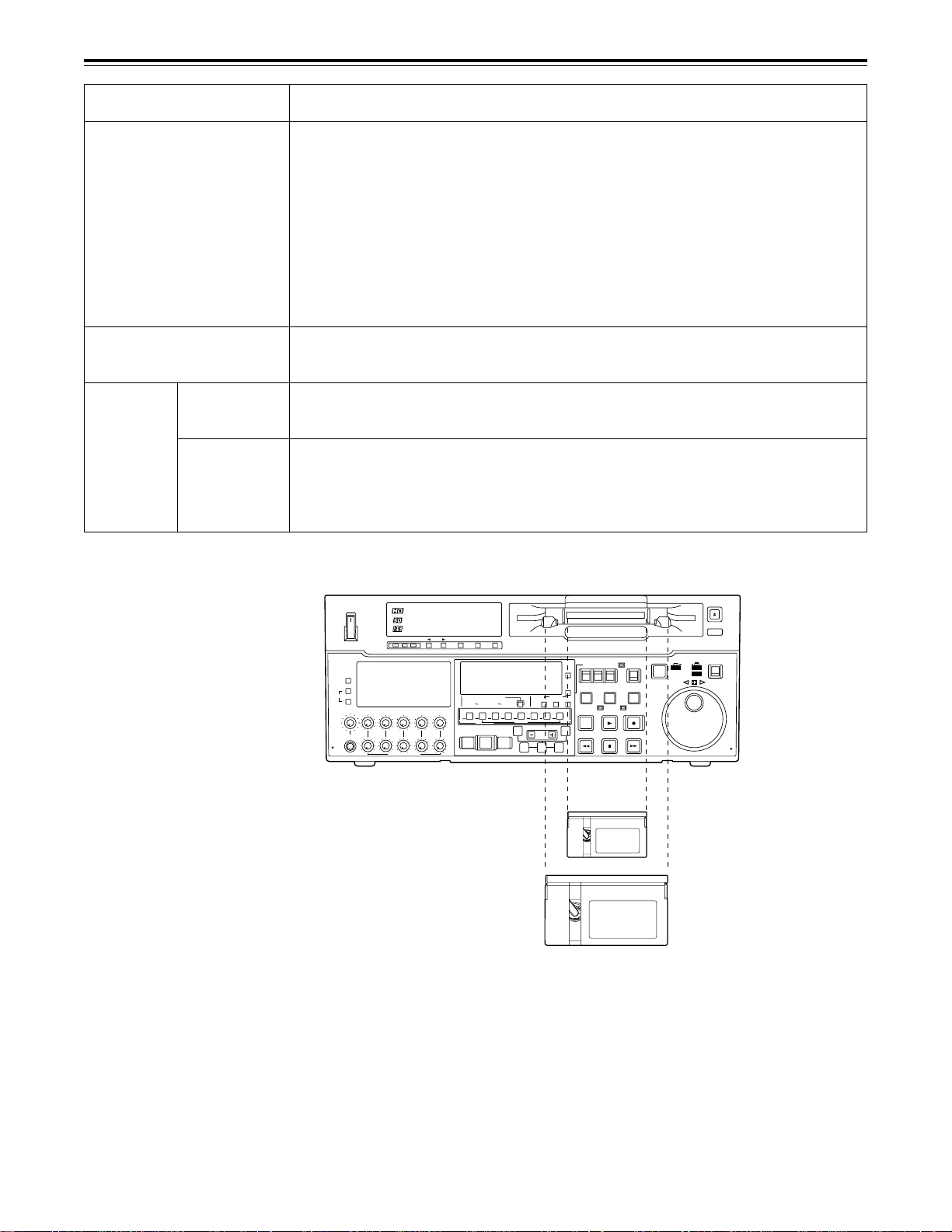
Tapes
Type
Consumer DV/DVCAM
cassette
(S size cassette)
M size cassette
DVCPROHD
(100 Mbps)
L size
cassette
For consumer
use DV/DVCAM
Align the cassette tape with the centre of the insertion slot, and gently push it inside. The cassette tape
is automatically loaded.
Description
These tapes are exclusively used with general consumer DV/DVCAMcamera/
recorder.
They can be played back on the unit if a cassette adapter AJ-CS750P available as
an optional accessory) is used. However, bear in mind that long-playing cassette
tapes (80 minutes in the standard mode; 120 minutes in the LP mode.) cannot be
used.
It is recommended that Panasonic’s consumer-use DV tapes for general
consumer applications be used.
Bear in mind that inserting one of these tapes without first installing the cassette
adapter will cause malfunctioning.
Tapes with a maximum playback time of maximum of 33 minutes. (AJ-5P23MP,
AJ-5P33MP)
Tapes with a maximum recording/playback time of maximum of 46 minutes. (AJHP32LP, AJ-HP46LP)
Standard playback cassette tapes for consumer use DV/DVCAM.
For playback, set the setup menu No.022 (PB FORMAT) to AUTO or setup menu
No.023 (FORMAT SEL) to DV or DVCAM.
Use of Panasonic’s consumer-use DV tapes is recommended.
PUSH
JOG SHTL
SLOW
REV FWD
EJECT
PULL
OPEN
ON
OFF
POWER
METER
FULL/FINE
L
MONITOR SELECT
R
LEVEL
CH 1/5 CH 2/6 CH 3/7 CH 4/8 CUE
HEADPHONES
PULL
OPEN
CH CONDITION ENTER ESCAPE SHIFT
AUDIO CH SELECT
CH
1
ASMBL
VIDEO
1
2 3 4 5 6 7 8
MULTICUE
REC
PREVIEW
AUTO EDIT
REVIEW
PULL FOR VARIABLE
PB
CH
4
CH 5CH
8
CH1/5 CH2/8 CH3/7 CH4/8 CUE TC
INSERT
A
IN
PREROLL
IN
SHIFT ADJ
TRIM
SET OUT
TC SET
M-cassette / ADAPTER
Caution: Do not insert S-cassette without adapter
MODE
TC INTTCTAPE
RESET
EXT EE
UB
TC/CTL
STAND BY
PLAYER
START
SERVO
EDIT PLAY
A
OUT
REW STOP
CONTROL
REMOTE
LOCAL
RECORDER
REC INHIBIT
REC
FF
M cassette
L cassette
<Notes>
General consumer tapes recorded in the LP mode cannot be played back.
•
The maximum speed at which general consumer DV/DVCAM tapes can be advanced is 32 times the
•
normal tape speed.
The maximum STILL mode time for general consumer DV/DVCAM tapes is set to 10 seconds..
•
Cueing up a general consumer DV/DVCAM tape at the same position should be kept to the minimum
•
in order to protect the tape from damage.
The maximum time for STILL TIMER when a general consumer DV/DVCAM tape is used is set to 10
•
seconds, and the total time during which such a tape may be left standing in the STILL mode is set to
1 minutes.
– 27 –
Page 28
Switching on the power/inserting the cassette
Before starting to operate the unit, check whether the equipment has been connected
properly.
1
Turn on the power.
2
Check that the AUTO OFF lamp is off.
When condensation has formed or some other trouble has occurred, the AUTO OFF
lamp lights, and all operations are disabled.
3
Insert the cassette tape.
Insert the tape at its proper position without force.
4
Check that the STOP lamp is on.
When the tape is inserted, the cylinder rotates automatically, the tape is loaded and the
unit goes into the stop mode. The EJECT lamp goes off.
13
ON
OFF
POWER
METER
FULL/FINE
L
MONITOR SELECT
R
LEVEL
CH 1/5 CH 2/6 CH 3/7 CH 4/8 CUE
HEADPHONES
PULL
OPEN
CH CONDITION ENTER ESCAPE SHIFT
AUDIO CH SELECT
CH 1
CH 4
ASMBL
VIDEO
1
2 3 4 5 6 7 8
MULTICUE
REC
PREVIEW
AUTO EDIT
REVIEW
PULL FOR VARIABLE
PB
INSERT
SHIFT ADJ
A
IN
TRIM
IN
SET OUT
CH 5 CH 8
CH1/5 CH2/8 CH3/7 CH4/8 CUE TC
PREROLL
M-cassette / ADAPTER
Caution: Do not insert S-cassette without adapter
TC INTTCTAPE
RESET
UB
TC/CTL
STAND BY
TC SET
START
EDIT PLAY
A
OUT
REW STOP
EXT EE
MODE
PLAYER
SERVO
CONTROL
REMOTE
LOCAL
RECORDER
REC INHIBIT
REC
FF
JOG SHTL
REV FWD
2
EJECT
PUSH
SLOW
PULL
OPEN
4
– 28 –
Page 29
STOP/STAND BY mode
1
When the STOP button is pressed, the unit goes into the stop mode. The STOP lamp
lights and the tape stops travelling.
In order to protect the tape, the unit goes into the standby OFF mode after the time set
•
by setup menu No. 400 (STILL TIMER) has elapsed. When the STOP, REW, FF or
PLAY button is pressed, the unit will go into the appropriate mode.
2
When the STAND BY button is pressed, the unit goes into the standby ON/OFF mode.
When the button’s lamp is lit, the unit is in the standby ON mode.
When the button is pressed during the stop mode, the unit goes into the standby OFF
mode and half-loading mode and the lamp goes off.
When the button is pressed during the standby OFF mode, the unit goes to the standby
ON mode.
Still Timer Setting
Page 81 indicates the settings for menu item 400-Still Timer set. Still Timer settings 4 and
below will best protect the tape.
2
ON
OFF
POWER
METER
FULL/FINE
L
MONITOR SELECT
R
LEVEL
CH 1/5 CH 2/6 CH 3/7 CH 4/8 CUE
HEADPHONES
PULL
OPEN
CH CONDITION ENTER ESCAPE SHIFT
AUDIO CH SELECT
CH
1
CH
ASMBL
VIDEO
1
2 3 4 5 6 7 8
MULTICUE
REC
PREVIEW
AUTO EDIT
REVIEW
PULL FOR VARIABLE
PB
4
CH 5CH
8
CH1/5 CH2/8 CH3/7 CH4/8 CUE TC
INSERT
A
IN
PREROLL
TRIM
IN
SET OUT
Caution: Do not insert S-cassette without adapter
RESET
TC/CTL
TC SET
SHIFT ADJ
START
A
OUT
M-cassette / ADAPTER
MODE
TC INTTCTAPE
EXT EE
UB
STAND BY
PLAYER
SERVO
EDIT PLAY
REW STOP
1
CONTROL
REMOTE
LOCAL
RECORDER
REC INHIBIT
REC
FF
PUSH
JOG SHTL
SLOW
REV FWD
EJECT
PULL
OPEN
– 29 –
Page 30

Recording
1
Set the accidental erasure prevention tab on the cassette tape to the “recording”
position and insert the tape.
2
Press the STOP button to place the unit in the stop mode.
3
Set the TAPE/EE switch to EE.
EE images now appear on the TV monitor.
4
Check that the REC INHIBIT lamp is off.
When this lamp is lit, select “0 (OFF)” as the setup menu item No.113 (REC INH)
setting.
5
Select the video and audio input signals and adjust their levels.
5-1 Selecting video/audio input signals
1 Connect the signals to be recorded.
2 Select the input signals on the setup menus No. 600 (VIDEO IN SEL) and
NO.700 (AUDIO IN SEL).
5-2 Adjusting the audio level
1 Adjust the levels of the audio input signals in the audio CH1, CH2, CH3, CH4,
CH5, CH6, CH7, CH8 and analogue cue channels selected by the setup menu
item No.700 setting. Normally, keep the audio input/output level controls \
pushed in (unity value).
The audio signals will be recorded at the proper level.
2 To adjust the recording level, pull out the controls \ and adjust them. With the
CUE signal, adjust the control in such a way that –20 dB will not be exceeded.
<Note>
When “CH1-CH4 (CH5-CH8)” is lit at the audio channel selector display Z, the audio
input/output level controls \ and level metre [ will operate for CH1-CH4 (CH5-CH8).
6
Press the PLAY button while holding down the REC button. The REC and PLAY lamps
light, and recording commences.
7
To end the recording, press the STOP button.
Recording is ended, and the unit goes into the stop mode.
<Note>
Check that the SERVO lamp is lit during recording. If it flashes or if it is off, the images
•
played back will be disturbed.
– 30 –
Page 31

Playback
1
Insert the cassette tape, and place the unit in the stop mode.
2
Press the PLAY button.
Regular playback is now commenced.
3
Adjust the audio playback level.
Pull out the audio level controls and turn them clockwise or counterclockwise to adjust
the levels. Normally, they are kept in the pushed-in state (unity value).
4
To end playback, press the STOP button.
The VTR now goes into the stop mode.
<Note>
Check that the SERVO lamp is lit during playback. If it flashes or if it is off, the images
•
played back will be disturbed.
– 31 –
Page 32

Jog/shuttle
Jog mode
Shuttle mode
1
Push the search dial to the “in” position.
Be sure that the JOG lamp lights.
2
Rotate the search dial.
The dial’s clickstops are cleared, and the tape is played back at the speed (–1× to +1×
normal speed) corresponding to the speed at which the dial is turned. When the dial
rotation is stopped, a still picture appears. The playback picture is noise-free.
3
To transfer from the jog mode to another mode, press the appropriate button.
1
Push the search dial to release it from the “in” position. The SHTL lamp lights, and the
unit goes into the shuttle mode.
Immediately after the power has been turned on, rotate the search dial and set it to the
•
centre position.
2
Set the SHTL/SLOW switch to SHTL or SLOW.
3
Rotate the search dial.
When the SHTL/SLOW switch has been set to SHTL, the playback picture speed is
varied from 0 to ±32× normal speed depending on the position of the dial. The playback
picture speed can be switched to ±8.4×, ±16× and ±32× normal speed with setting
menu No. 101 (SHTL MAX).
The dial’s centre position is a clickstop where a still picture appears as the playback
image. When the SHTL/SLOW switch has been set to SLOW, the playback picture
speed is varied from –4.1 to +4.1× normal speed depending on the position of the dial.
The maximum speed can be selected using the setup menu No. 308 (VAR FWD MAX)
and No. 309 (VAR REV MAX). However, noise appears at speeds other than –1 to +1×
normal speed.
The dial’s centre position is a clickstop where a still picture appears as the playback
image. The playback picture is noise-free.
4
To transfer from the shuttle mode to another mode, press the STOP button or other
button.
<Note>
When the unit leaves the factory, its operation is set up so that it will be transferred to the
•
shuttle or jog mode when the search dial is rotated. If it is inconvenient for operation to be
transferred to the variable-speed mode directly, it can also be transferred through the
search button.
Set setup menu No. 100 (SEARCH ENA) to KEY.
– 32 –
Page 33

Manual editing
1
2
3
4
5
Select the editing mode.
ASSEMBLE: For assemble editing.
INSERT: For insert editing.
Select the editing channel.
In the case of insert editing, press the channel button corresponding to the signals to be
edited, and check that its lamp is on.
Press the PLAY button.
Search for the position where the editing is to be commenced (IN point) while viewing
the TV monitor, and press the PLAY and EDIT buttons together at the IN point.
Press the STOP or PLAY button at the position where editing is to be completed (OUT
point) while viewing the TV monitor. The unit goes into the stop mode, and editing is
completed.
– 33 –
Page 34

Preroll
1
Press the PREROLL button.
The VTR now performs the preroll operation.
When the edit IN point has been entered, the tape is rewound from the edit IN point for
•
the duration set by setup menu “000,” and the unit then goes into the stop mode.
When the edit IN point has not been entered, the tape is rewound for the duration set
•
by setup menu “000” from the position where the button was pressed, and the unit
then goes into the stop mode.
<Notes>
The time code or CTL signal must be continuously recorded between the edit IN point and
•
preroll point.
When the IN point has not been entered, whether to enter the IN point and perform preroll
•
or to perform preroll without entering the IN point can be selected at setup menu No. 305
(AUTO ENTRY).
– 34 –
Page 35

Automatic editing (deck to deck)
Editing refers to the job of using a prerecorded tape to produce a complete recording by
joining together separate cuts and deleting unnecessary parts.
The basic steps taken for editing are as follows.
1
Set the CONTROL switch to REMOTE on the player and to LOCAL on the recorder.
2
Select the editing mode.
3
Enter the edit points of the recorder and player.
4
Check and modify the edit points.
5
Check (Preview) before proceeding with the editing.
6
Proceed with the editing.
7
Check (Review) the recording that has resulted from the editing.
– 35 –
Page 36

Automatic editing (deck to deck)
Set the time counter display to TC or CTL.
Set the POWER switch to ON.
Set the CONTROL
switch to REMOTE.
Adjust the playback level.
ON
AUDIO CH SELECT
SHIFT ADJ
TC SET
START
TC/CTL
RESET
TC INTTCTAPE
UB
STAND BY
EDIT PLAY
REW STOP
SERVO
REC
FF
REC INHIBIT
PLAYER
EXT EE
MODE
REMOTE
PUSH
REV FWD
RECORDER
LOCAL
CONTROL
CH
1
1
ASMBL
PREVIEW
REVIEW
AUTO EDIT
PREROLL
TRIM
A
IN
IN
SET OUT
A
OUT
MULTICUE
INSERT
VIDEO
CH1/5 CH2/8 CH3/7 CH4/8 CUE TC
CH
4
OFF
POWER
CH CONDITION ENTER ESCAPE SHIFT
METER
FULL/FINE
MONITOR SELECT
LEVEL
HEADPHONES
CH 1/5 CH 2/6 CH 3/7 CH 4/8 CUE
REC
L
R
PB
PULL FOR VARIABLE
PULL
OPEN
PULL
OPEN
CH 5CH
8
2 3 4 5 6 7 8
JOG SHTL
SLOW
EJECT
M-cassette / ADAPTER
Caution: Do not insert S-cassette without adapter
Switch settings and adjustments
When the unit is used as the recorder:
Set the POWER switch
to ON.
ON
OFF
POWER
METER
FULL/FINE
L
MONITOR SELECT
R
LEVEL
HEADPHONES
PULL
OPEN
CH CONDITION ENTER ESCAPE SHIFT
CH 1/5 CH 2/6 CH 3/7 CH 4/8 CUE
PULL FOR VARIABLE
AUDIO CH SELECT
CH
1
CH
4
ASMBL
VIDEO
1
2 3 4 5 6 7 8
MULTICUE
REC
PREVIEW
AUTO EDIT
REVIEW
PB
TC SET
CH 5CH
CH1/5 CH2/8 CH3/7 CH4/8 CUE TC
PREROLL
SHIFT ADJ
8
INSERT
A
IN
TRIM
IN
SET OUT
M-cassette / ADAPTER
Caution: Do not insert S-cassette without adapter
MODE
TC INTTCTAPE
RESET
EXT EE
UB
TC/CTL
STAND BY
START
A
OUT
PLAYER
SERVO
EDIT PLAY
REW STOP
Set the CONTROL
switch to LOCAL.
CONTROL
REMOTE
LOCAL
RECORDER
REC INHIBIT
REC
FF
PUSH
JOG SHTL
SLOW
REV FWD
EJECT
PULL
OPEN
Adjust the recording level.
When the unit is used as the player:
Set the time counter display to TC or CTL.
– 36 –
Page 37

Automatic editing (deck to deck)
Selecting the editing mode
1
Select the editing mode.
For assemble editing, press the ASMBL button.
For insert editing, press the INSERT button.
ASSEMBLE: The assemble editing mode (in which cuts are joined together) is
established.
INSERT: The insert editing mode (in which cuts are inserted) is established.
2
Select the editing channel.
With assemble editing, the ASMBL lamp lights.
With insert editing, press the button of the channel whose signals are to be edited and
light its lamp.
3
Select the VTR to be operated (this setting is performed when editing with 2 VTRs).
Press the PLAYER or RECORDER button to select the VTR.
PLAYER: Press this button to operate the player VTR and enter the edit points.
RECORDER: Press this button to operate the recorder VTR (this unit) and enter the
edit points.
ON
OFF
POWER
METER
FULL/FINE
L
MONITOR SELECT
R
LEVEL
CH 1/5 CH 2/6 CH 3/7 CH 4/8 CUE
HEADPHONES
PULL
OPEN
CH CONDITION ENTER ESCAPE SHIFT
AUDIO CH SELECT
CH
1
CH
ASMBL
VIDEO
1
2 3 4 5 6 7 8
MULTICUE
REC
PREVIEW
AUTO EDIT
REVIEW
PULL FOR VARIABLE
PB
1, 2
4
CH 5CH
8
CH1/5 CH2/8 CH3/7 CH4/8 CUE TC
INSERT
A
IN
PREROLL
TRIM
IN
SET OUT
Caution: Do not insert S-cassette without adapter
RESET
TC/CTL
TC SET
SHIFT ADJ
START
A
OUT
M-cassette / ADAPTER
MODE
TC INTTCTAPE
EXT EE
UB
STAND BY
PLAYER
SERVO
EDIT PLAY
REW STOP
3
CONTROL
REMOTE
LOCAL
RECORDER
REC INHIBIT
REC
FF
PUSH
JOG SHTL
SLOW
REV FWD
EJECT
PULL
OPEN
– 37 –
Page 38

Automatic editing (deck to deck)
Entering the edit points
1
Search for the edit IN point by performing the jog or shuttle operation.
Establish the still picture mode at the desired position.
Refer to page 32 for details on the jog/shuttle operations.
2
Press the IN and SET buttons together.
The edit IN point is now entered.
The edit IN point value now appears on the display.
3
Search for the edit OUT point by performing the jog or shuttle operation.
Establish the still picture mode at the desired position.
Refer to page 32 for details on the jog/shuttle operations.
4
Press the OUT and SET buttons together.
The edit OUT point is now entered.
The edit OUT point value now appears on the display.
ON
OFF
POWER
METER
FULL/FINE
L
MONITOR SELECT
R
LEVEL
HEADPHONES
PULL
OPEN
CH CONDITION ENTER ESCAPE SHIFT
CH 1/5 CH 2/6 CH 3/7 CH 4/8 CUE
PULL FOR VARIABLE
AUDIO CH SELECT
CH
1
CH
4
ASMBL
VIDEO
1
2 3 4 5 6 7 8
MULTICUE
REC
PREVIEW
AUTO EDIT
REVIEW
PB
TC SET
INSERT
SHIFT ADJ
A
IN
TRIM
IN
SET OUT
CH 5CH
8
CH1/5 CH2/8 CH3/7 CH4/8 CUE TC
PREROLL
M-cassette / ADAPTER
Caution: Do not insert S-cassette without adapter
MODE
TC INTTCTAPE
RESET
EXT EE
UB
TC/CTL
STAND BY
START
A
OUT
PLAYER
SERVO
EDIT PLAY
REW STOP
CONTROL
REMOTE
LOCAL
RECORDER
REC INHIBIT
REC
FF
PUSH
JOG SHTL
SLOW
REV FWD
EJECT
PULL
OPEN
2, 4
1, 3
Match frame processing function
When using two VTRs for editing, a total of four edit points—namely, the player’s IN and OUT
points and the recorder’s IN and OUT points—need to be entered. However, since the last
edit point is calculated automatically, only three of these edit points must be entered.
Negative duration function
This function is used by combining setup menu No. 300 (IN/OUT DEL) and No. 301 (NEGA
FLASH).
– 38 –
Page 39

Automatic editing (deck to deck)
Checking the edit points
1
Press the IN (or OUT) button to check the edit point.
The value of the entered edit point appears on the display.
2
Press the PREROLL button while holding down the IN (or OUT) button to check the
image at the edit point.
The tape is cued at the edit IN (or OUT) point, and the still picture mode at that point is
displayed.
The EE mode is established if the TAPE/EE switch has been set to the “EE” position
•
when “STOP” has been selected for the setup menu No. 307 (AFTER CUE-UP).
3
Press the IN and OUT buttons together to check the edit duration.
The duration time appears on the display.
Calculating the duration
•When both edit points have been set, the duration between the two edit points.
•When only one edit point has been set, the duration between the set data and the current
tape address.
•When neither edit point has been set, the duration of the previously edited interval.
ON
OFF
POWER
METER
FULL/FINE
L
MONITOR SELECT
R
LEVEL
CH 1/5 CH 2/6 CH 3/7 CH 4/8 CUE
HEADPHONES
PULL
OPEN
CH CONDITION ENTER ESCAPE SHIFT
AUDIO CH SELECT
CH
1
CH
ASMBL
VIDEO
1
2 3 4 5 6 7 8
MULTICUE
REC
PREVIEW
AUTO EDIT
REVIEW
PULL FOR VARIABLE
PB
4
CH 5CH
8
CH1/5 CH2/8 CH3/7 CH4/8 CUE TC
INSERT
A
IN
PREROLL
2
TRIM
IN
SET OUT
1, 3
Caution: Do not insert S-cassette without adapter
RESET
TC/CTL
TC SET
SHIFT ADJ
START
A
OUT
M-cassette / ADAPTER
MODE
TC INTTCTAPE
EXT EE
UB
STAND BY
PLAYER
SERVO
EDIT PLAY
REW STOP
CONTROL
REMOTE
LOCAL
RECORDER
REC INHIBIT
REC
FF
PUSH
JOG SHTL
SLOW
REV FWD
EJECT
PULL
OPEN
– 39 –
Page 40

Automatic editing (deck to deck)
ON
AUDIO CH SELECT
SHIFT ADJ
TC SET
START
TC/CTL
RESET
TC INTTCTAPE
UB
STAND BY
EDIT PLAY
REW STOP
SERVO
REC
FF
REC INHIBIT
PLAYER
EXT EE
MODE
REMOTE
PUSH
REV FWD
RECORDER
LOCAL
CONTROL
CH
1
1
ASMBL
PREVIEW
REVIEW
AUTO EDIT
PREROLL
TRIM
A
IN
IN
SET OUT
A
OUT
MULTICUE
INSERT
VIDEO
CH1/5 CH2/8 CH3/7 CH4/8 CUE TC
CH
4
OFF
POWER
CH CONDITION ENTER ESCAPE SHIFT
METER
FULL/FINE
MONITOR SELECT
LEVEL
HEADPHONES
CH 1/5 CH 2/6 CH 3/7 CH 4/8 CUE
REC
L
R
PB
PULL FOR VARIABLE
PULL
OPEN
PULL
OPEN
CH 5CH
8
2 3 4 5 6 7 8
JOG SHTL
SLOW
EJECT
M-cassette / ADAPTER
Caution: Do not insert S-cassette without adapter
2
1
3-
1
, 3-
2
Modifying the edit points
1
Re-entering the edit points
Search for the new edit point by performing the jog or shuttle operation, and press the
IN (or OUT) and SET buttons together to re-enter the edit point.
2
Modifying the edit point in frame units (trim function)
Press the TRIM button while holding down the IN (or OUT) button.
The edit point is put ahead by 1 frame each time the + button is pressed.
The edit point is put back by 1 frame each time the – button is pressed.
3
Resetting the edit points
3-1 Resetting both the edit IN and OUT points
Press the RESET button.
•
3-2 Resetting either the edit IN or OUT point
Press the RESET button while holding down the IN (or OUT) button.
•
<Notes>
Edit points can be reset only in the CTL mode.
•
An edit OUT point can be reset even while editing is in progress.
•
The IN and OUT points are automatically reset during the eject mode.
•
– 40 –
Page 41

Automatic editing (deck to deck)
Preview
1
After the edit points have been entered, press the PREVIEW button.
Normal preview is now performed.
<Notes>
If the edit IN point has not been entered, the position where the PREVIEW button was
•
pressed will be entered at the edit IN point.
To stop the preview at any time, press the STOP button.
•
If the PREVIEW button is pressed again while preview is in progress after the IN point,
•
preview will start again from the beginning.
When the edit OUT point is reached, the unit automatically goes into the stop mode.
•
ON
OFF
POWER
METER
FULL/FINE
L
MONITOR SELECT
R
LEVEL
HEADPHONES
PULL
OPEN
CH CONDITION ENTER ESCAPE SHIFT
CH 1/5 CH 2/6 CH 3/7 CH 4/8 CUE
PULL FOR VARIABLE
AUDIO CH SELECT
CH 1
CH 4
ASMBL
VIDEO
1
2 3 4 5 6 7 8
MULTICUE
REC
PREVIEW
AUTO EDIT
REVIEW
PB
TC SET
INSERT
SHIFT ADJ
A
IN
TRIM
IN
SET OUT
CH 5 CH 8
CH1/5 CH2/8 CH3/7 CH4/8 CUE TC
PREROLL
M-cassette / ADAPTER
Caution: Do not insert S-cassette without adapter
MODE
TC INTTCTAPE
RESET
UB
EXT EE
TC/CTL
STAND BY
START
A
OUT
PLAYER
SERVO
EDIT PLAY
REW STOP
CONTROL
REMOTE
LOCAL
RECORDER
REC INHIBIT
REC
FF
PUSH
JOG SHTL
SLOW
REV FWD
EJECT
PULL
OPEN
1
– 41 –
Page 42

Automatic editing (deck to deck)
Executing automatic editing
1
Press the AUTO EDIT button.
Automatic editing is now performed.
To stop the editing at any time, press the STOP button.
•
When the edit OUT point is reached, the unit goes into the stop mode after postrolling.
•
Postroll
With assemble editing, editing continues for approx. 2 seconds even after the edit OUT point
has been passed, the tape is rewound to the OUT point, and the unit goes into the stop
mode.
With insert editing, the unit goes into the play mode after the edit OUT point has been
passed, the tape is rewound to the OUT point, and the unit goes into the stop mode.
Retry function
If the AUTO EDIT button is pressed again after the STOP button has been pressed to stop
the editing, editing will start again from the beginning.
Auto tag editing
If the AUTO EDIT button is pressed when the next edit point has not yet been entered upon
completion of editing, the previous edit OUT point will be entered as the IN point, and editing
is performed accordingly.
To release the auto tag mode, press one of the tape transport buttons (PLAY, etc.).
<Note>
The entered points are automatically cleared after editing is executed. However, the
•
previous editing points can be recalled by pressing the TRIM+ (or TRIM–) and SET buttons
together.
EJECT
ON
OFF
POWER
METER
FULL/FINE
L
MONITOR SELECT
R
LEVEL
CH 1/5 CH 2/6 CH 3/7 CH 4/8 CUE
HEADPHONES
PULL
OPEN
CH CONDITION ENTER ESCAPE SHIFT
AUDIO CH SELECT
CH 1
CH 4
ASMBL
VIDEO
1
2 3 4 5 6 7 8
MULTICUE
REC
PREVIEW
AUTO EDIT
REVIEW
PULL FOR VARIABLE
PB
INSERT
SHIFT ADJ
A
IN
TRIM
IN
SET OUT
CH 5 CH 8
CH1/5 CH2/8 CH3/7 CH4/8 CUE TC
PREROLL
M-cassette / ADAPTER
Caution: Do not insert S-cassette without adapter
TC INTTCTAPE
RESET
UB
TC/CTL
STAND BY
TC SET
START
EDIT PLAY
A
OUT
REW STOP
EXT EE
PLAYER
MODE
SERVO
CONTROL
REMOTE
LOCAL
RECORDER
REC INHIBIT
REC
FF
PUSH
JOG SHTL
SLOW
REV FWD
1
PULL
OPEN
– 42 –
Page 43

Automatic editing (deck to deck)
Review
1
Upon completion of the editing, press the REVIEW button.
The review is started in the recorder.
To stop the review at any time, press the STOP button.
•
When the edit OUT point is reached, the unit goes into the stop mode after postrolling.
•
ON
OFF
POWER
METER
FULL/FINE
L
MONITOR SELECT
R
LEVEL
HEADPHONES
PULL
OPEN
CH CONDITION ENTER ESCAPE SHIFT
CH 1/5 CH 2/6 CH 3/7 CH 4/8 CUE
PULL FOR VARIABLE
AUDIO CH SELECT
CH 1
CH 4
ASMBL
VIDEO
1
2 3 4 5 6 7 8
MULTICUE
REC
PREVIEW
AUTO EDIT
REVIEW
PB
TC SET
INSERT
SHIFT ADJ
A
IN
TRIM
IN
SET OUT
CH 5 CH 8
CH1/5 CH2/8 CH3/7 CH4/8 CUE TC
PREROLL
M-cassette / ADAPTER
Caution: Do not insert S-cassette without adapter
MODE
TC INTTCTAPE
RESET
EXT EE
UB
TC/CTL
STAND BY
START
A
OUT
PLAYER
SERVO
EDIT PLAY
REW STOP
CONTROL
REMOTE
LOCAL
RECORDER
REC INHIBIT
REC
FF
PUSH
JOG SHTL
SLOW
REV FWD
EJECT
PULL
OPEN
1
– 43 –
Page 44

Audio split editing
The video edit points and audio edit points can be entered separately, and they can be offset
from each other and edited.
The audio edit points cannot be entered when the assemble editing mode has been
selected. After the edit points have been entered, follow the same operating procedure as
that for insert editing.
■ Entering the edit points
Video IN point: Press the SET button while holding down the IN button.
Video OUT point: Press the SET button while holding down the OUT button.
Audio IN point: Press the SET button while holding down the A-IN button.
Audio OUT point: Press the SET button while holding down the A-OUT button.
■ Deleting the edit points
Video IN point: Press the RESET button while holding down the IN button.
Video OUT point: Press the RESET button while holding down the OUT button.
Audio IN point: Press the RESET button while holding down the A-IN button.
Audio OUT point: Press the RESET button while holding down the A-OUT button.
■ Modifying the edit points
Video IN point: Press the TRIM+ or TRIM– button while holding down the IN button.
Video OUT point: Press the TRIM+ or TRIM– button while holding down the OUT button.
Audio IN point: Press the TRIM+ or TRIM– button while holding down the A-IN button.
Audio OUT point: Press the TRIM+ or TRIM– button while holding down the A-OUT button.
ON
OFF
POWER
METER
FULL/FINE
L
MONITOR SELECT
R
LEVEL
CH 1/5 CH 2/6 CH 3/7 CH 4/8 CUE
HEADPHONES
PULL
OPEN
CH CONDITION ENTER ESCAPE SHIFT
AUDIO CH SELECT
CH
1
CH
ASMBL
VIDEO
1
2 3 4 5 6 7 8
MULTICUE
REC
PREVIEW
AUTO EDIT
REVIEW
PULL FOR VARIABLE
PB
4
CH 5CH
8
CH1/5 CH2/8 CH3/7 CH4/8 CUE TC
INSERT
A
IN
PREROLL
TRIM
IN
SET OUT
A-IN
button
Caution: Do not insert S-cassette without adapter
RESET
TC/CTL
TC SET
SHIFT ADJ
START
A
OUT
A-OUT
button
M-cassette / ADAPTER
MODE
TC INTTCTAPE
EXT EE
UB
STAND BY
PLAYER
SERVO
EDIT PLAY
REW STOP
CONTROL
REMOTE
LOCAL
RECORDER
REC INHIBIT
REC
FF
PUSH
JOG SHTL
SLOW
REV FWD
EJECT
PULL
OPEN
– 44 –
Page 45

Audio split editing
■ Displaying the audio split edit points
The edit points are displayed on the front panel as shown below. (The figure shows an audio
IN point.)
Operations
Video IN point: Press the IN button.
Video OUT point: Press the OUT button.
Audio IN point: Press the A-IN button.
Audio OUT point: Press the A-OUT button.
<Note>
If the editing mode is switched to assemble editing after audio edit points have entered,
these points will be deleted.
■ Cueing up the tape to the edit points
Cue-up to video IN point: Press the PREROLL button while holding down the IN button.
Cue-up to video OUT point: Press the PREROLL button while holding down the OUT button.
Cue-up to audio IN point: Press the PREROLL button while holding down the A-IN button.
Cue-up to audio OUT point: Press the PREROLL button while holding down the A-OUT
button.
■ Duration display
The duration can be displayed on the front panel only.
Duration from video IN point to OUT point: Press the IN and OUT buttons simultaneously.
Duration from audio IN point to OUT point:Press the A-IN and A-OUT buttons simultaneously.
Match frame processing mechanism
When two VTRs are used for audio split editing operations, there will be a total of eight edit
points: two pairs of video IN and OUT points, one for the player and the other for the
recorder, and two pairs of audio IN and OUT points, one for the player and the other for the
recorder. Since the remaining three points are automatically calculated when five of these
eight edit points are entered, up to five edit points can be entered.
■ When a VTR without a split editing function is to be used as the
player
When a VTR which does not have the ability to set the video and audio edit points separately
is used as the player, split editing can still be performed by setting the audio In and OUT
points using the recorder and setting the data of three points as the video edit points.
<Note>
If, during audio split editing, only the video OUT point (or audio OUT point) is entered and
automatic editing is executed without the audio OUT point (or video OUT point) having been
entered, editing will continue until the audio OUT point (or video OUT point) is entered or the
STOP button is pressed to suspend operation.
– 45 –
Page 46

Expansion mode execution using the MODE/SEL button
When the MODE/SEL button g is pressed, the MULTI CUE operation mode which is an expansion
mode can be established as shown in the diagram below.
Normal mode
MODE/SEL button g
OPERATION MODE SEL
MULTI CUE
SCROLL
Button (2)5
SCROLL
Button(1) 5
OPERATION MODE SEL
IC CARD
SCROLL
Button (2)5
SCROLL
Button(1) 5
OPERATION MODE SEL
VAR MEMO
SCROLL
Button (2)5
SCROLL
Button(1) 5
OPERATION MODE SEL
ERROR LOG
SCROLL
Button (2)5
SCROLL
Button(1) 5
<Expansion mode selection> status
ENTER
Button 6
ESCAPE
Button 7
ENTER
Button 6
ESCAPE
Button 7
ENTER
Button 6
ESCAPE
Button 7
ENTER
Button 6
ESCAPE
Button 7
EXIT button h
MULTI CUE operation mode
IC CARD operation mode
VARIABLE MEMORY mode
ERROR LOG operation mode
<Expansion mode> status
ESCAPE 7
or
EXIT button h
<Expansion mode selection> status
When the MODE/SEL button g is pressed in the normal mode, the following appears on the front top
display.
OPERATION MODE SEL
MULTI CUE
When SCROLL button 5 is pressed, it causes IC CARD # VAR MEMO ... change in order. Select a
desired mode and press ENTER button 6.
– 46 –
Page 47

MULTI CUE function
Selecting the MULTI CUE mode
The MULTI CUE mode can be selected from the <Expansion mode selection> status established by
pressing the MODE/SEL button g.
When the EXIT button h is pressed, the MULTI CUE mode is released, and the normal mode is
restored.
Editing channels
In handling the cue points, the edit CH selection buttons (ASMBL, VIDEO, CH1/5, CH2/6, CH3/7, CH4/
8, CUE, TC) can be used for CUE¢1 through CUE¢8, respectively.
AB
CUEAB A: Indicates the page (page 0 to 9).
B: Indicates the cue point (point 1 to 8).
Registering the cue points
A total of 80 cue points can be registered on a maximum of 10 pages. By deciding on the setting for
setup menu item No.131 (PAGE MODE: AUTO/MANU), the following operation modes for registering
the cue points can be selected.
• Operation where 8 cue points can be registered on the same page which has been selected
• Operation where the next page is automatically selected as soon as the page on which cue points are
now being registered becomes full, registration is continued and a total of 80 cue points can be
registered on a maximum of 10 pages
Furthermore, by deciding on the setting for setup menu item No.132 (ROTA MODE: ON/OFF) setting,
the following operation modes can be selected when all the cue points have been registered.
• Operation where the registration operation is not performed
• Operation where the registration operation is performed (if MANU has been selected as the setup
menu item No.131 (PAGE MODE) setting, a cue point is registered in CUE¢1 on the page concerned;
if AUTO has been selected, it is registered in CUE01 on page 0.
When the MULTI CUE mode has been selected, the following functions are established.
• No editing can be performed in the MULTI CUE mode.
• When operation has been transferred to the MULTI CUE mode in the edit mode selection status, the
edit CH selection buttons (ASMBL, VIDEO, CH1/5, CH2/6, CH3/7, CH4/8, CUE, TC) are released
automatically.
• The MULTI CUE function cannot be used for deck-to-deck operations in the MULTI CUE mode.
– 47 –
Page 48

MULTI CUE function
Description of displays
When MULTI CUE is selected using the MODE/SEL button g, the following appears on the front top
panel display 3.
1 Mode display
2 Search point or registration point time
(display is blank when no data is available)
M#LST
EACRUCEH011!
4 Search display
3 Display mode selection mark
1Mode display: This indicates that the unit is now operating in the MULTI CUE mode.
2Time display: This indicates the time of the search point or registration point. (This display is blank
when no data is available.)
3Display mode selection mark: This shows whether the current LED and time data indicate the
search point or registration point. (As shown in the figure below, the display is switched using the
SHIFT button 8 on the top panel.)
M#LST
EACRUCEH011!
MLST
EACRUCEH01
4Search point: This indicates the search point which has currently been selected. (SEARCH01 #
CUE1 on page 0)
5Registration point: This indicates the point to be registered when the SET button is next pressed.
(ENTRY23 # CUE3 on page 2)
2:3E4N:T5R6Y:2030
5 Registration
point
2:3E4N:T5R6Y:2030
SHIFT
00:#5E4N:T3R2Y:2130
!
Page operations
The page can be scrolled forward or backward using the scroll buttons 5 on the front top panel.
• Page scrolling in the forward direction is performed as follows depending on the setting selected for
• In scrolling the pages in the reverse direction, it is not possible to move from page 0 to page 9.
setup menu item No.132 (ROTA MODE).
When OFF is selected: It is not possible to move from page 9 to page 0.
When ON is selected: It is possible to move from page 9 to page 0.
– 48 –
Page 49

MULTI CUE function
Search point and registration point operations
Each time the SHIFT button 8 is pressed, the search point display mode and registration point display
mode are selected alternately. Perform the search point operations in the search point display mode
and the registration point operations in the registration point display mode.
• When the power is turned on, the search and registration points established are the ones which were
in place when the power was last turned off.
• When the setup menu item No.131 (PAGE MODE) or No.132 (ROTA MODE) setting is changed,
CUE01 (CUE1 on page 0) applies as both the search and registration pointer.
Search point operations
When the following display has appeared on the front top panel, search pointer operations can be
performed. The LED corresponding to the search point selected flashes, and the number of the point is
displayed on the top panel.
Example of top panel display
Example of LED display
• The search pointer position is changed directly on the same page by pressing the CUE¢1 through ¢8
(ASMBL through TC) buttons.
• When the display page has been changed using the scroll buttons 5, operation is as follows
depending on the setup menu item No.131 (PAGE MODE) setting.
When MANU has been set: Both the search and registration pointers move to CUE¢1 on the page
When AUTO has been set: Only the search pointer moves to CUE¢1 on the page which has been
M#LST
EACRUCEH011!
ASMBL
1
Flashing Lit
which has been changed.
changed: the registration pointer does not move.
VIDEO
CH1/5 CH2/8 CH3/7 CH4/8 CUE TC
2 3 4 5 6 7 8
(points already
registered)
2:3E4N:T5R6Y:2030
Off
(points not yet
registered)
Registration point operations
Registration pointer operations can be performed when the following display appears on the front top
panel. When the SET button T has been pressed, the LED corresponding to the point that has been
registered will start flashing.
Example of LED display
ASMBL
1
VIDEO
CH1/5 CH2/8 CH3/7 CH4/8 CUE TC
2 3 4 5 6 7 8
Lit
(points already
registered)
Flashing
Off
(points not yet
registered)
– 49 –
Page 50

MULTI CUE function
Example of top panel display: One of the following two displays appears depending on the registration
conditions.
When a point has not been
registered yet
When a point has already
been registered
• The registration pointer position is changed directly on the same page by pressing the CUE¢1
through ¢8 (ASMBL through TC) buttons.
• When the display page has been changed using the scroll buttons, operation is as follows depending
on the setup menu item No.131 (PAGE MODE) setting.
When MANU has been set: Both the search and registration pointers move to CUE¢1 on the page
When AUTO has been set: Only the registration pointer moves to CUE¢1 on the page which has
Registering cue points
Operation is as follows depending on the setup menu item No.131 (PAGE MODE) setting.
Operations on the same selected page (PAGE MODE = MANU)
• Operations are performed on the selected page.
• The page is selected using the scroll buttons 5.
• When the SET button T alone is pressed, the cue points are registered in the sequence shown below
on the selected page.
CUE¢1 # CUE¢2#
MLST
EACRUCEH01
MLST
EACRUCEH01
which has been changed.
been changed: the search pointer does not move.
......
# CUE¢7 # CUE¢8
:
# EN:TRY:16!
00:#5E4N:T3R2Y:1160
!
• Operation is automatically ended when CUE¢8 is registered on the page. When the next cue point is
to be registered, the registration pointer must be moved.*
Check that the registration display mode is established, and change the page to automatically change
the registration pointer. In this case, the search pointer also moves automatically to the top (CUE¢1)
of the new page. To change the pointer on the same page, press the CUE button directly.
* When ON has been selected as the setup menu item No.132 (ROTA MODE) setting, a rotation
operation is performed for the cue points on the same page as follows.
# CUE¢1 # CUE¢2#
......
# CUE¢7 # CUE¢8 #
– 50 –
Page 51

MULTI CUE function
Operation for automatically moving to the next page and continuing
with registration when the cue point registration page has become full
(PAGE MODE = AUTO)
• When the page on which the cue points are being registered has become full, operation automatically
moves to the next page, and registration is continued. When CUE98 on the last page is reached,
operation is automatically ended.*
When the next cue point is to be registered, the registration pointer must be moved.
Check that the registration display mode is established, and change the page to automatically change
the registration pointer. In this case, the search pointer does not change.
To change the pointer on the same page, press the CUE button directly.
* When ON has been selected as the setup menu item No.132 (ROTA MODE) setting, a rotation
operation for the cue points from page 9 (CUE98) to page 0 (CUE01) is performed.
When no more cue points can be registered in either of the above two
operation modes
•“¢¢” appears as the registration pointer display.
• In the registration display mode, the FULL MEMORY message appears when a registration point
display operation (when the SET button is pressed) has been performed.
• Any LEDs which are flashing now stop flashing.
(Even if some of the points have not been registered, the FULL MEMORY message will appear.)
MLST
EACRUCEH01
<Note>
When ON has been selected as the setup menu item No.132 (ROTA MODE) setting, there is never a
time when it is not possible for registration points to be registered.
FUL#L
ENMTERMY
O¢R¢Y
!
– 51 –
Page 52

MULTI CUE function
When registering cue points using numbers
While holding down the ADJ button Y among the time code buttons on the front panel, press the
SHIFT button Y to establish the cue point registration mode. After setting the duration to be registered
on the bottom panel using the SHIFT button and ADJ button (same operation as the TCG registration
operation), the setting can be registered by pressing the SET button T.
Bottom panel
When the SET button is pressed,
the setting is registered.
Deleting registered points
Deleting all the points
• By pressing the ESCAPE button 7 while holding down the SET button T, all the LEDs of the buttons
in which cue points have been registered go off, and the registered points are released. The range of
the pointers which are deleted is as follows depending on the setup menu item No.131 (PAGE MODE)
setting.
When MANU has been set: All the pointers on the current page are deleted.
When AUTO has been set: All the pointers on all the pages are deleted.
• The search and registration pointers are set as follows depending on the setup menu item No.131
(PAGE MODE) setting.
When MANU has been set: The pointers automatically return to the top (CUE¢1) of the same
When AUTO has been set: The pointers automatically return to the top (CUE01) of the first page.
• These operations are acknowledged regardless of whether the search point or registration point
display mode is established.
Resetting the registration points individually
• By pressing the ESCAPE button 7 while holding down the button among the CUE1 to 8 buttons that
corresponds to the particular point to be deleted, the button (LED) corresponding to the point
registered goes off, and the registered point is deleted.
• This operation is acknowledged only in the registration point display mode.
(When the search point display mode is established, the registered point is not deleted even when the
ESCAPE button 7 is pressed.)
CT
0 0
: : :
0 0 0 0 0 0
page.
Search operations
By pressing the PREROLL button Q, prerolling can be performed for the cue point whose LED is
flashing in the search point display mode.
The tape will not be prerolled if the cue point is not registered.
Since the tape is not prerolled even if the PREROLL button Q is pressed in the registration point
display mode, be absolutely sure to check that the search point display mode has been established.
[Aside from the regular preroll time, the time selected by the setup menu item No.011 (CU-ROLL TIME)
is valid as the preroll time in this mode.]
– 52 –
Page 53

IC CARD function
IC CARD mode selection
In <Expansion mode selection> status with MODE/SEL button g pressed, IC CARD mode can be
selected.
When EXIT button h is pressed, the mode changes from IC CARD to normal mode.
Outline
The management of the setup menu using IC CARD, and system file and user file (USER1~USER5)
loading (reading from IC card)/saving (storing into IC card) can be performed.
Load/Save
Load/Save
Load/Save
IC CARD
<Note>
The system file and user file (USER2-USER5) are provided with a lock mode to protect the settings.
The system file can be set by the setup menu No. 30 (MENU LOCK), and the user file, by the setup
menu No. A03 (MENU LOCK).
In the above menu, loading (reading from IC card) is executed even when the lock mode has been set.
* Usable cards are battery replaceable SRAM cards (64KB or over) of 68-pin two-piece type.
It is recommended to use Model BN-064HSR.
Load/Save
Load/Save
Load/Save
SYSTEM
USER1
USER2
USER3
USER4
USER5
– 53 –
Page 54

IC CARD function
Description of Display
When IC CARD function is selected, the following information will be displayed at the VTR status
display 3.
1 Mode display 2 File select display
C!ALROD
F ILE 1±2∫345s
AD
4 Execute status display 5 File status display
3 Battery display
1 Mode display: It indicates that the unit is operating in IC CARD mode.
2 File select display: All the relevant file names are displayed, and when an intended file is
selected, the file name will be displayed blinking. (In a state of default, 1
blinks, showing that USER1 is to be operated.)
File name
1
2
3
4
5
s
It stands for user file (USER1).
It stands for user file (USER2).
It stands for user file (USER3).
It stands for user file (USER4).
It stands for user file (USER5).
It stands for system file.
Description
3 Battery display: It indicates the state of exhaustion of the battery built in IC card.
Status display
Blank
!
Battery is not exhausted.
Battery is exhausted. (Replace with new one.)
Description of operation
4 Execute status
display: When it is operated with respect to the intended file, the execute status will be
displayed during the period of execution.
Status display
SAVE
LOAD
LOCK
DELETE
FORMAT
It reads the intended file from VTR and stores it in IC card.
It reads the intended file from IC CARD and stores it in VTR.
It makes the file stored in IC card write inhibited or write permitted.
It deletes the file stored in IC card.
It formats the IC card.
Description of operation
5 File status display: It indicates the state of the file stored in IC card.
Status display
Blank
±
∫
No file is stored.
File is stored.
File stored is in a state of being write inhibited.
Description
– 54 –
Page 55

IC CARD function
Description of Operation
The following key operation is possible with respect to IC CARD function.
Function
File selection
SAVE
LOAD
LOCK
DELETE
FORMAT
Key operation
TRIM button U
SET button T + IN button T
SET button T + OUT buttonT
SET button T + SHIFT button Y
SET button T + RESET button Y
SET button T + REC button =
It selects the intended file.
It reads the intended file from VTR and stores it in IC card.
It reads the intended file from IC CARD and stores it in VTR.
It makes the file stored in IC CARD write inhibited or write
permitted.
It deletes the file stored in IC card.
It formats the IC card.
Description of operation
File selection
With TRIM button pressed, the file selected changes as follows:
J
!#!#!#!#!#!#
12345
5
S
1 2 3 4 5
J
TRIM button + : File changes from 1 # 2 ... in order.
TRIM button – : File change from 5 # 4 ... in order.
<Note>
Do not take out the IC card during operation on IC card. It may otherwise cause damage to the content
of the IC card.
Warning Message
When IC CARD mode is selected, the following warning message is sometimes displayed at the VTR
status display 3.
In that case, cancel the warning according to the instruction.
IC card is not inserted: Insert the IC card.
NO CARD
IC card is not formatted: Format the IC card according to the instruction.
UNFOMATTED CARD
Operation on IC card is inhibited: When REMOTE/LOCAL switch J is set at “REMOTE,” the
following warning message will appear and it is inhibited to operate on IC card. Shift the switch to
“LOCAL”.
IC Card i s inval id
– 55 –
Page 56

Variable memory function
Variable memory function
Variable memory mode selection
In <Expansion mode selection> status with MODE/SEL button g pressed, variable mode can be
selected.
When EXIT button h is pressed, variable mode is cancelled and changed to normal mode.
Outline
The unit is provided with two variable memory functions as follows. These functions can be used in
variable memory mode.
• Variable memory playback: The tape is played back in VAR mode within a specific range, and the
change in speed is stored in the memory. The tape can be played back
at the memorized speed.
• Variable memory editing: Using the unit as a controller (deck to deck mode recorder) to control
the playback speed of the player, editing can be performed in speed
variable mode.
Variable memory playback operation procedure
Variable memory playback operation can be performed according to the following procedure in variable
memory mode.
1 Register IN point by using SET button T and IN button T.
It is not needed to set OUT point for variable memory playback.
2 Set the initial speed (– 1.0 to + 1.0) by the search dial P while pressing SET button T.
3 Simultaneously pressing both SET button T and PREVIEW/REVIEW button S results
in automatic profiling, then the tape is played back at the set initial speed up to the IN
point.
4 After passing the IN point, turn the search dial P to memorize the playback speed.
5 Press STOP button > to stop the tape.
6 When PREVIEW/REVIEW button S is pressed, variable memory playback is per-
formed at the memorized speed.
<Notes>
• After passing the IN point, the tape is played back reproducing the content of memory and keeps
running at the final speed of the content until STOP button > is pressed.
• The content stored in the memory will be cleared in a mode other than the variable memory mode.
Also, the memory will be cleared with power switch 1 turned OFF.
– 56 –
Page 57

Variable memory function
Variable memory editing operation procedure
Variable memory editing operation can be performed according to the following procedure, setting the
unit connected as a recorder to variable memory mode.
1 Select the edit mode by pressing ASMBL button V or desired INSERT button W.
2 Select VTR to be operated by pressing RECORDER or PLAYER button E.
3 Register IN/OUT point by using SET button T and IN/OUT button T.
The OUT point of PLAYER cannot be registered.
4 After selecting VTR of PLAYER by pressing PLAYER button E, set the initial speed by
the search dial P while pressing SET button T.
5 Simultaneously pressing both SET button T and PREVIEW/REVIEW button S results
in automatic profiling for both PLAYER and RECORDER, then the VTR of PLAYER is
operated at the set initial speed up to the IN point.
6 After passing the IN point, turn the search dial P to memorize the playback speed of VTR.
7 When the tape has passed the OUT point set by RECORDER, the memory of the
playback speed will terminate.
8 When AUTO EDIT button R is pressed, variable memory editing is executed. Once
editing has been executed, the memorized speed will be cleared. The initial speed will
not be cleared however.
9 The result of editing can be checked by pressing PREVIEW/REVIEW button S.
<Notes>
• The content stored in the memory will be cleared in a mode other than the variable memory mode.
Also, the memory will be cleared with power switch 1 turned OFF.
• Phase adjustment is not made during playback to the IN point of variable memory editing.
– 57 –
Page 58

ERROR LOG function
ERROR LOG mode selection
In <Expansion mode selection> status with MODE/SEL button g pressed, ERROR LOG mode can be
selected.
When EXIT button h is pressed, ERROR LOG mode is cancelled and changed to normal mode.
Outline
In case the following warning message is given during tape running, the time code and operation mode
as well as the warning message will be stored, which can be read in the form of a list at VTR status
display 3.
It is possible to store up to 99 warnings. Also, in case of more than 99 warnings, it will be processed
according to the setting of setup menu No. 015 (AUTO STEP).
Warning message to be stored
NO RF
SV NOT LOCKED
LOW RF
HIGH ERROR RATE
Description
Blank portion of tape was detected more than 1 sec. (Normal playback
mode)
Servo was unlocked for over 3 sec. (Record/Normal playback/Edit mode)
Envelop level detected was about 1/3 of the normal level for over 1 sec.
(Record/Normal playback/Edit mode)
Error rate worsened, and video or audio playback signal was subjected to
correction/calibration. (Normal playback mode)
<Description of Menu>
Setup menu No.015 (AUTO STEP) (Default setting is OFF)
In ERROR LOG function, warning can be stored up to 99 messages. If it exceeds the capacity,
processing mode will be selected for storage.
OFF: Upper limit is 99 messages. Warning messages generated after that are not stored.
ON : 99 messages are stored. Warning messages given after that are stored in the place of 99th
message. Warning messages already stored are then shifted down in the direction of smaller
numbers in order.
• The image of storage with it set to ON is illustrated below.
Store No.
1/99
2/99
99/99
Warning stored
Warning 1
Warning 2
:
:
:
:
Warning 99
Stored up to 99
messages, and
100th message
was given.
Store No.
1/99
2/99
:
:
99/99
Warning stored
Warning 2
Warning 3
:
:
Warning 100
– 58 –
Page 59

ERROR LOG function
Description of Display
When ERROR LOG function is selected, the following information will be displayed at the VTR status
display 3.
PSLVAY
3 Operation mode display 4 Time code display
1 Warning display: Warning message stored is displayed.
2 Warning store status display: Store No. of warnings displayed and the number of all warnings
3 Operation mode display: Operation mode with warning stored is displayed.
4 T ime code display: Time code with warning stored is displayed.
Description of Operations
1 Warning display 2 Warning store status display
TLO2C4K:E5D
NO
9:3559/:5209
are displayed.
The following key operations are possible with respect to ERROR LOG function.
Function
Selection
ALL CLEAR
CUE UP
SCROLL button 5
RESET button Y
PREROLL button Q
Key operation
Description of operation
Warning message stored can be scrolled up and down.
Warning message stored can be cleared all together.
Cueing up to the relevant point can be made with respect
to the warning selectively displayed.
– 59 –
Page 60

Setup (default settings)
The unit’s major settings are performed by making selections on menus.
The setting menus appear on the TV monitor when the TV monitor and VIDEO OUT 3
connector in the unit’s connector area are hooked up.
Changing the settings
1
Press the MENU button.
The setup menu appears on the TV monitor and setup menu No. appears on the
counter display. (If the setup has already been performed, the screen showing the
changes made last will appear.)
2
Rotate the search dial and select the item to be set.
The cursor (*) on the menu screen moves and the item No. on the display flashes.
When the dial is rotated clockwise, the item No. is incremented from 001→002→
•
003→004 and so on; when it is rotated counterclockwise, the item No. is decremented.
The search dial should be used in jog mode if at all possible.
•
Hold down the PLAY button and press the FF (next major item) or REW (previous
•
major item) buttons to select the menu by major item.
3
While holding down the search button, rotate the search dial at the position where the
change is to be made.
The setting No. now flashes.
When the dial is rotated clockwise, the setting value is incremented; when it is rotated
counterclockwise, it is decremented.
4
Release the search button when the setting is completed.
The setting value on the menu screen and display flashes.
During the SHTL mode, the item moves if the search dial is not at the STILL position.
•
<Note>
When the RESET button is
•
pressed to return to the
factory settings, the factory
settings are restored only for
the user file currently being
used and other user files are
not affected.
The changed SYSTEM
•
menu contents are recorded
even if the MENU button is
pressed.
5
Repeat steps 2 through 4 to change another item.
6
Press the SET button.
The changes are now stored in the memory.
To return the items to the settings established before the changes were made, press
•
the MENU button.
To return the setup settings to the factory (default) settings, press the RESET button
while the menu is displayed. The following message will now appear:
SETUP-MENU INIT SET
YES<PLAY>/NO<STOP>
When the PLAY button is pressed, the factory settings are restored.
4
3
M-cassette / ADAPTER
SHIFT ADJ
TRIM
SET OUT
1234
TC SET
PROG MENU
Caution: Do not insert S-cassette without adapter
MODE
TC INTTCTAPE
RESET
UB
EXT EE
TC/CTL
STAND BY
START
A
OUT
PLAYER
EDIT PLAY
REW STOP
MODE/SEL
EXIT
SERVO
CONTROL
REMOTE
LOCAL
RECORDER
REC INHIBIT
REC
FF
MENU SET DIAG
PUSH
JOG SHTL
REV FWD
ON
OFF
POWER
METER
FULL/FINE
L
MONITOR SELECT
R
LEVEL
CH 1/5 CH 2/6 CH 3/7 CH 4/8 CUE
HEADPHONES
PULL
OPEN
CH CONDITION ENTER ESCAPE SHIFT
AUDIO CH SELECT
CH
1
CH
ASMBL
VIDEO
1
2 3 4 5 6 7 8
MULTICUE
REC
PREVIEW
AUTO EDIT
REVIEW
PULL FOR VARIABLE
PB
SET UP
STATUS
4
CH 5CH
8
CH1/5 CH2/8 CH3/7 CH4/8 CUE TC
INSERT
A
IN
PREROLL
IN
PROG
STATUS
SAVE/
123
MENU
EXIT
SLOW
EJECT
PULL
OPEN
– 60 –
1
6
2
Page 61

Setup menus
This unit can store up to 5 user files (user 1 to user 5) containing different menu settings, and
these files can be selected and used.
Changing the file
1
Press the MENU button.
2
Hold down the STAND BY button and press the FF button to switch to the next user file.
Hold down the STAND BY button and press the REW button to switch to the previous
user file.
FF
REW
SYSTEM USER 1 USER 2 USER 3 USER 4 USER 5
FF
REW
FF
REW
USER FILE
Each user file contains the following items.
•
•
•
•
•
•
•
•
•
FF
REW
BASIC
OPERATION
INTERFACE
EDIT
TAPE PROTECT
TIME CODE
VIDEO
AUDIO
MENU
FF
REW
FF
REW
3
Repeat the operation in step 2 to select the user file to be used and press the SET
button. The user file is changed and stored in the memory.
<Note>
SYSTEM menu items are not included in user files 1 to 5.
Therefore, after selecting the user file, switch to the SYSTEM file and set the SYSTEM menu
items.
– 61 –
Page 62

Setup menus
Lock mode can be set to protect the settings in the system files and user files (USER2 –
USER5). Settings can no longer be changed when this mode is set.
To set and release the lock mode for the system files and user files use setup item No. 30
(MENU LOCK) and setup menu item No. A03 (MENU LOCK), respectively.
Setting and releasing the lock mode.
1
Press the MENU button.
2
While holding down the STAND BY button, press the REW or FF button, and select the
file for which the lock mode is to be set or released.
3
Turn the search dial and move the cursor (¢) on the menu screen to setup item No. 30
(MENU LOCK) or setup menu item No. A03 (MENU LOCK) for the system or user file.
4
While holding down the search button, turn the search dial and select lock mode setting
or release.
To set the lock: Select the 0001 (ON) setting.
To release the lock: Select the 0000 (OFF) setting.
When the lock has been set, “LOCKED” flashes on the menu screen.
SETUP-MENU LOCKED
<USER2> No.800 – 0005
¢000 P–ROLL TIME 5s
001 LOCAL ENA ST&EJ
002 TAPE TIMER ±12h
003 REMAIN SEL OFF
004 SYNCHRONIZE OFF
005 SUPER ON
006 DISPLAY SEL T&STA
007 CHARA H-POS 6
008 CHARA V-POS 23
5
Press the SET button. The setting is now stored in the memory.
<Note>
• The lock mode cannot be set for the USER1 file settings.
• Even if the RESET button is pressed, the files which has been set to the lock mode cannot
be reset to the factory settings.
– 62 –
Page 63

Setup menus
The contents of the USER2 – USER5 files can be copied (loaded) into the USER1 file. In
addition, the contents of the USER1 file can be copied (saved) to the USER2 – USER5 files.
USER1 USER2
Load or save
Load or save
Load or save
Load or save
USER3
USER4
USER5
Settings can be locked.
Settings can be locked.
Settings can be locked.
Settings can be locked.
Loading a user file
1
Press the MENU button.
2
While holding down the STANDBY button, press the REW or FF button, and select
USER1.
3
Turn the search dial and move the cursor (¢) on the menu screen to setup item No. A00
(LOAD).
SETUP-MENU MENU
<USER1> NO.A00 - 0000
759 REC PT MUTE OFF
¢A00 LOAD USER2
A01 SAVE USER2
A02 P.ON LOAD OFF
END
4
While holding down the search button, turn the search dial and select the user file
whose contents are to be loaded into USER1.
5
Press the SET button. The following messages appear on the menu screen and
counter display.
Menu screen
SETUP-MENU LOAD
USER2 → USER1 OK?
YES<PLAY>/NO<STOP>
The user file number selected in step 4 is displayed in the shaded area.
6
Press the PLAY button. The settings of the user file selected in step 4 are loaded, and
the USER1 menu display appears. When the STOP button is pressed, the USER1
menu display appears while the settings remain unchanged.
7
Turn the search dial and move the cursor (¢) on the menu screen to any setup item
except No. A00 (LOAD) and No. A01 (SAVE).
8
Press the SET button. The USER1 settings are now stored in the memory.
If the USER1 settings are not going to be stored in the memory, do not press the SET
button but press the MENU button.
– 63 –
Page 64

Setup menus
Saving a user file
1
Press the MENU button.
2
While holding down the STAND BY button, press the REW or FF button, and select
USER1.
3
Turn the search dial and move the cursor (¢) on the menu screen to setup item No. A01
(SAVE).
SETUP-MENU MENU
<USER1> NO.A00 - 0000
759 REC PT MUTE OFF
A00 LOAD USER2
¢A01 SAVE USER2
A02 P.ON LOAD OFF
END
4
While holding down the search button, turn the search dial and select the user file into
which the USER1 contents are to be saved. User files which have been set to the lock
mode are not displayed. When all the user files have been set to the lock mode, the
“LOCKED” display appears and the contents cannot be saved.
5
Press the SET button. The following messages appear on the menu screen and
counter display.
Menu screen
SETUP-MENU SAVE
USER1 → USER2 OK?
YES<PLAY>/NO<STOP>
The user file number selected in step 4 is displayed in the shaded area.
6
Press the PLAY button. The contents of the USER1 file are saved in the user file which
was selected in step 4 and stored in the memory. When the STOP button is pressed,
the USER1 menu display appears while the settings remain unchanged.
7
Turn the search dial and move the cursor (¢) on the menu screen to any setup item
except No. A00 (LOAD) and No. A01 (SAVE).
8
Press the SET button. The USER1 settings are now stored in the memory.
If the USER1 settings are not going to be stored in the memory, do not press the SET
button but press the MENU button.
Automatic loading of user file when the power is turned on
When the user file to be loaded is selected in advance using setup menu item No. A02
(P.ON LOAD), it can be automatically loaded into USER1 when the power is turned on.
– 64 –
Page 65

Setup menus
SYSTEM menu
<SYSTEM>
Item Setting
Superimposed
No.
00 WFM SEL 0000 CTL
05 ENCODER 0000 REMOTE
06 V LEVEL 0000 HD
The underline on the setting item denotes the initial setting.
display display
SEL 0001 LOCAL
CTRL 0001 SD
Superimposed
No.
0001 TC
0002 VIDEO
0003 SYNC
0004 RF-L
0005 RF-R
0006 ENV-L
0007 ENV-R
0002 BOTH
0002 BOTH
This selects the signal to output from the VIDEO OUT 2
connector.
0: The CTL signal is output.
1: The TIME CODE signal is output.
2: The VIDEO OUT signal is output.
3: The SYNC signal is output.
4: The PB L RF signal is output.
5: The PB R RF signal is output.
6: The PB L ENV signal is output.
7: The PB R ENV signal is output.
<Note>
1. The settings can be changed at any time regardless of the
setup menu item No. 30 (MENU LOCK) setting.
2. The signals which are output during normal playback have
approximately the levels given below.
CTL: 0.1 to 0.3 Vp-p TC: 0.6 Vp-p
VIDEO: 1.0 Vp-p
This selects whether the video output signal is to be adjusted
on the VTR or with the external encoder remote control.
0: Video output signals are adjusted with the external encoder
remote control.
1: Video output signals are adjusted on the VTR.
2: Each adjustment of video output signal is made from the
encoder remote controller of this unit and external
equipment.
The output levels can be selected when adjusting video output
levels from external encoder remote controller.
0: HD video output level can be selected.
1: SD video output level can be selected.
2: HD/SD video output levels can be selected.
Description
Video output signal adjustments
A control matrix of the adjustments is shown below.
Settings Item adjusted
05: ENCODER SEL
REMOTE
<Note>
When the external
encoder remote controller
(AJ-ER50, option) is
used, VIDEO PHASE
and SYS PHASE of the
encoder remote controller
will not operate.
LOCAL
BOTH
Ext. encoder remote: Ext. encoder remote adjustment only.
Unit: Setup menu adjustment only.
Ext. encoder remote/Unit: Simultaneous adjustment from external encoder remote and setup menu is possible
06: V LEVEL CTRL
HD
SD
BOTH
HD
SD
BOTH
HD
SD
BOTH
but the result of adjustment from external encoder remote will not be reflected in the
setup menu.
650: Y LVL (HD)
651: P
B LVL (HD)
652: PR LVL (HD)
653: BK LVL (HD)
External encoder remote controller
Not adjustable
Ext. encoder remote controller
Unit
Ext. encoder remote controller/Unit
Unit
Ext. encoder remote controller/Unit
654: Y LVL (SD)
655: P
656: PR LVL (SD)
657: BK LVL (SD)
Not adjustable
External encoder remote controller
External encoder remote controller
Unit
Unit
Ext. encoder remote controller/Unit
Ext. encoder remote controller/Unit
B LVL (SD)
– 65 –
Page 66

Setup menus
SYSTEM menu
<SYSTEM> (continued)
Item Setting
Superimposed
No.
12 SYS H 0550 –550
13 V PHASE 0000 –500
14 SYS SC 0000 –108
15 VO SYS 0000 –429
16 SDI SYS 0000 –429
17 V PHASE 0000 –190
18 SCH COAR 0000 0
19 SCH FINE 0000 –32
The underline on the setting item denotes the initial setting.
display display
(HD)*1 : :
(HD)*1 : :
2
(SD)*
2
H (SD)*
2
H (SD)*
2
(SD)*
2
(SD)*
2
(SD)*
Superimposed
No.
This enables the system phase to be adjusted in 27ns steps.
–: The phase is advanced.
1100 0
::
1650 550
0500 0
::
1000 500
::
0108 0
::
0216 108
::
0429 0
::
0858 429
::
0429 0
::
0858 429
::
0190 0
::
0380 190
0001 90
0002 180
0003 270
::
0032 0
::
0064 32
+: The phase is delayed.
<Note>
If setting
return to factory (default) setting.
This enables the video system phase to be adjusted in 27ns
steps.
–: The phase is advanced.
+: The phase is delayed.
<Note>
In the case of the HD up-converter output from the SD
playback tape (when the option has been installed), the video
phase is fixed.
This enables the system phase to be adjusted in a total
variable range of +/–180 degrees or more.
–: The phase is advanced.
+: The phase is delayed.
<Note>
If setting
return to factory (default) setting.
This enables the video out system phase to be adjusted in
74ns steps.
–: The phase is advanced.
+: The phase is delayed.
<Note>
If setting
return to factory (default) setting.
This enables the SDI OUT system phase to be adjusted in
74ns steps.
–: The phase is advanced.
+: The phase is delayed.
<Note>
If setting
return to factory (default) setting.
This enables the video system phase to be adjusted in 148ns
steps.
–: The phase is advanced.
+: The phase is delayed.
<Note>
In the case of the SD down-converter output from the HD
playback tape (when the option has been installed), the video
phase is fixed.
This enables the SCH phase to be adjusted in 90-degree
steps.
–: The phase is advanced.
+: The phase is delayed.
(The SC phase changes but the H phase remains
unchanged.)
This enables the SCH phase to be adjusted in a total variable
range of +/–45 degrees or more.
–: The phase is advanced.
+: The phase is delayed.
(The SC phase changes but the H phase remains
unchanged.)
Description
operation is performed, the setting value does not
operation is performed, the setting value does not
operation is performed, the setting value does not
operation is performed, the setting value does not
*1: With the HD output (HD tape playback or up-conversion output)
*2: With the SD output (SD tape playback or down-conversion output)
– 66 –
Page 67

Setup menus
SYSTEM menu
<SYSTEM> (continued)
Item Setting
Superimposed
No.
20 AV PHASE 0000 –100
30 MENU 0000 OFF
The underline on the setting item denotes the initial setting.
display display
LOCK 0001 ON
Superimposed
No.
This enables the phase of the audio output to be adjusted to
::
0100 0
::
0200 100
the video output by 20.8¨s.
–: The audio output phase is moved ahead of the video output.
+: The audio output phase is delayed from the video output.
This selects whether to establish or release the system file
lock mode.
0: The system file lock is released (changes can be made).
1: The system file lock is engaged (no changes can be made).
Description
– 67 –
Page 68

Setup menus
USER menu
<BASIC>
Item Setting
Superimposed
No.
000 P-ROLL 0000 0S
001 LOCAL 0000 DIS
002 TAPE 0000 ±12h
003 REMAIN 0000 OFF
004 SYNCHRO- 0000 OFF
005 SUPER 0000 OFF
The underline on the setting item denotes the initial setting.
display display
TIME : :
ENA
TIMER 0001 24h
SEL 0001 ON
NIZE 0001 ON
Superimposed
No.
This sets the preroll time which can be set from 0 to 15
seconds in 1-second increments.
0005 5S
::
0015 15S
0001 ST&EJ
0002 ENA
0001 ON
0002 SW
<Note>
When the unit is set to automatic editing [PREVIEW, AUTO
EDIT], the unit will not operate if the preroll time is set to 0
seconds.
This selects the buttons which can be operated on the front panel
when the REMOTE/LOCAL switch has been set to REMOTE.
0: No buttons can be operated.
1: Only the STOP and EJECT buttons can be operated.
2: All buttons except for the RECORDER and PLAYER
buttons can be operated.
This selects the 12 or 24 hour display for the CTL counter.
0: 12 hour display
1: 24 hour display
This selects whether the REMAIN (remaining tape time)
display is to be superimposed onto the HD SDI OUT3, SD SDI
OUT3 and VIDEO OUT3 connector signals.
0: Display is not superimposed.
1: Display is superimposed.
<Note>
1. Even when “1: ON” is selected, the remaining tape time will
not be displayed while this is being calculated after a tape
has been ejected or inserted.
2. The remaining tape time is not displayed when TIME has
been selected as the setup menu item No.006 (DISPLAY
SEL) setting.
This sets whether the phase is to be synchronized between
two decks.
0: The phase is not synchronized. The edit points will be off
by several frames but editing can be entered more quickly.
1: The phase is synchronized. Error-free editing can be
performed.
This selects whether the time code and other displays are to
be superimposed onto the HD SDI OUT3, SD SDI OUT3 and
VIDEO OUT3 connector signals.
0: Displays are not superimposed.
1: Displays are superimposed.
2: Pressing PLAY button after pressing SET button (front
panel bottom e ) selects the super display ON/OFF.
<Note>
Pressing SET button after pressing PLAY button results in
same operation as in normal PLAY button pressing.
Description
– 68 –
Page 69

Setup menus
USER menu
<BASIC> (continued)
Item Setting
Superimposed
No.
006 DISPLAY 0000 TIME
007 CHARA 0000 0
008 CHARA
009 CHARA 0000 WHITE
010 MONI 0000 MANU
The underline on the setting item denotes the initial setting.
display display
SEL
H-POS
V-POS 0000 0
TYPE 0001 W/OUT
CONTROL 0001 AUTO
Superimposed
No.
This selects what displays such as the time code are to be
0001 T&STA
0002 T&S&M
0003 T&RT
0004 T&YMD
0005 T&MDY
0006 T&DMY
::
0006 6
::
0037 37
::
0023 23
::
0032 32
superimposed onto the HD SDI OUT3, SD SDI OUT3 and
VIDEO OUT3 connector signals.
0: Time only
1: Time and operation mode
2: Time, operation mode and mode
3: Time and REC TIME
4: Time and REC DATE (year, month, day)
5: Time and REC DATE (month, day, year)
6: Time and REC DATE (day, month, year)
<Note>
1. The following modes are displayed in accordance with the
format used.
2. With the 2 (T&S&M) setting, an error message is displayed
when a warning or error has occurred.
3. REC TIME and REC DATE are displayed only in DV/DVCAM
format playback mode. Operation mode is displayed in
DVCPROHD/DVCPRO50/DVCPRO format mode.
This selects the horizontal position of the characters used for
the time code and other displays which are superimposed
onto the HD SDI OUT3, SD SDI OUT3 and VIDEO OUT3
connector signals.
<Note>
1. When this item has been set, the output is given to each
OUT3 connector in a state of DISPLAY SEL even with
SUPER OFF. However, when MENU is exited, the displays
comply with the SUPER OFF or ON setting.
CHARA TYPE is output to the each OUT3 connector in the
status set on the MENU.
This selects the vertical position of the characters used for the
time code and other displays which are superimposed onto
the HD SDI OUT3, SD SDI OUT3 and VIDEO OUT3
connector signals.
<Note>
1. When this item has been set, the output is given to each
OUT3 connector in a state of DISPLAY SEL even with
SUPER OFF. However, when MENU is exited, the displays
comply with the SUPER OFF or ON setting.
CHARA TYPE is output to the each OUT3 connector in the
status set on the MENU.
This selects the display type for the SETUP MENU, etc. and
the displays superimposed onto the HD SDI OUT3, SD SDI
OUT3 and VIDEO OUT3 connector signals.
0: White characters on a black background
1: White characters with black edges
This sets whether the recorder is to be forcibly set to the EE
status and the player’s playback signals are to be output to
the monitor by pressing the PLAYER button on the recorder
when the monitor has been connected only to the recorder
during deck-to-deck editing.
0: The EE status is not forcibly established.
1: The EE status is forcibly established, and the player’s
playback signals are output.
Description
<Format> <Display>
DVCPROHD # DVCPRO_HD
DVCPRO50 # DVCPRO_50
DVCPRO # DVCPRO
DV # DV
DVCAM # DVCAM
– 69 –
Page 70

Setup menus
USER menu
<BASIC> (continued)
Item Setting
Superimposed
No.
011 CU-ROLL 0000 0s
015 AUTO STEP 0000 OFF
020 SYS FORMAT 0000 1080i
022 PB FORMAT 0000 MANUAL
023 FORMAT SEL 0000 HD
The underline on the setting item denotes the initial setting.
display display
TIME :
Superimposed
No.
For setting the preroll time in the MULTI CUE mode.
This can be set in 1-second increments from 0 to 15 seconds.
0005 5s
::
0015 15s
In ERROR LOG function, warning can be stored up to 99
0001 ON
0001 720p
0001 AUTO
0001 422
0002 411
0003 420p
0004 DV
0005 DVCAM
messages. If it exceeds the capacity, processing is selected
for storing the messages.
0: Upper limit is 99 messages. Warning messages generated
after that are not stored.
1: 99 messages are stored. Warning messages given after
that are stored in the place of 99th message. Warning
messages already stored are then shifted down in the
direction of smaller numbers in order.
This selects the recording format of this unit.
0: 1080i is selected.
1: 720p is selected.
This selects the tape playback format.
0: Comply with the setup menu No.023 (FORMAT SEL)
setting.
1: Comply with the format recorded in the tape.
This selects the format when the setup menu No.022 (PB
FORMAT) is set to MANUAL.
0: Comply with the setup menu No.020 (SYS FORMAT)
setting.
1: DVCPRO50 (422) format is selected.
2: DVCPRO (411) format is selected.
3: DVCPRO50 (420p) format is selected.
4: DV format is selected.
5: DVCAM format is selected.
Description
Format in tape playback
022: PB FORMAT
MANUAL
AUTO
• In the eject mode, the format will follow the setup menu No.020 (SYS FORMAT).
• When setup menu No.022 (PB FORMAT) is set at AUTO, the format with format not detected (tape
inserted) will follow the setup menu No.023 (FORMAT SEL). With DV/DVCAM selected, the unit
operates regarding that HD has been selected.
020: SYS FORMAT
1080i
720p
–––
– 70 –
023: FORMAT SEL
HD
422
411
420p
DV
DVCAM
HD
422
411
420p
DV
DVCAM
–––
Playback format
DVCPROHD (1080i)
DVCPRO50 (422)
DVCPRO (411)
DVCPRO50 (420p)
DV
DVCAM
DVCPROHD (720p)
DVCPRO50 (422)
DVCPRO (411)
DVCPRO50 (420p)
DV
DVCAM
DVCPROHD (1080i)/DVCPROHD (720p)/
DVCPRO50 (422)/DVCPRO (411)/
DVCPRO50 (420p)/DV/DVCAM
Auto detect
Page 71

Setup menus
USER menu
<BASIC> (continued)
Item Setting
Superimposed
No.
030 HD 0000 59.94
031 OUT REF 0000 AUTO
The underline on the setting item denotes the initial setting.
display display
FREQUENCY 0001 60
Superimposed
No.
0001 INPUT
0002 HD_REF
0003 SD_REF
This selects the HD frequency.
0: The 59.94 Hz frequency is selected.
1: The 60 Hz frequency is selected.
The field frequency set here is used only when no signals
corresponding to the OUT REF setting are input. If the
corresponding signals are input, the field frequency matches
the field frequency of the input.
This selects the video output reference.
0: When the HD REF input signal is present, this signal
serves as the reference.
When the HD REF input signal is not present but the SD
REF input signal is present, the SD REF signal serves as
the reference.
When neither the HD REF input signal nor SD REF input
signal is present, the HD serial signal serves as the
reference.
When none of the HD REF input, SD REF input and HD
serial signals are present, the internal sync signal serves
as the reference.
1: When the HD serial input signal is present, this signal
serves as the reference.
2: The signal which has been supplied to the HD REF IN
connector serves as the reference.
3: The signal which has been supplied to the SD REF IN
connector serves as the reference.
Description
– 71 –
Page 72

Setup menus
USER menu
<OPERATION>
Item Setting
Superimposed
No.
100 SEARCH 0000 DIAL
101 SHTL MAX 0000 ×8.4
102 FF. REW 0000 ×16
104 REF 0000 OFF
105 AUTO EE 0000 S/F/R
106 EJECT EE 0000 EE
The underline on the setting item denotes the initial setting.
display display
ENA 0001 KEY
MAX 0001 ×32
ALARM 0001 ON
SEL 0001 STOP
SEL 0001 BLACK
Superimposed
No.
0001 ×16
0002 ×32
0002 ×50
0003 ×60
0004 ×100
0002 GRAY
This selects the direct search dial operation.
0: For direct search dial operations.
1: Operation is not transferred to the search mode unless the
search button is pressed.
This sets the maximum speed for shuttle operations.
0: 8.4× normal speed
1: 16× normal speed
2: 32× normal speed
<Note>
Depending on the tape format, the actual tape travel speed
will differ slightly from what the superimposed display shows.
This sets the maximum speed for FF and REW operations.
0: 16 × normal speed
1: 32 × normal speed
2: 50 × normal speed
3: 60 × normal speed
4: 100 × normal speed
<Note>
The maximum speed is automatically limited to 50× for
DVCPROHD and 32× for DV or DVCAM.
This selects whether to warn the operator when the
REF.VIDEO signal has not been connected.
0: Warning is not given.
1: Warning is given by the flashing STOP lamp.
This selects the VTR mode in which the EE status is to be
established when the TAPE/EE switch has been set to EE.
0: The EE status is established in the stop, FF or REW mode.
1: The EE status is established in the stop mode only.
<Note>
The EE output with the DVCPRO50, DVCPRO, DV or DVCAM
format is characterized by a black picture and muted sound.
With setup menu No.118 (SD MODE INH) OFF, EE output is
given in DVCPRO50/DVPRO format mode.
This selects the video and audio output statuses in the eject
mode.
0: The EE status is always established regardless of the
TAPE/EE switch position.
1: The statuses depend on the TAPE/EE switch position:
EE: The EE status is established.
TAPE: The video signals turn black; the audio signals are
2: The statuses depend on the TAPE/EE switch position:
EE: The EE status is established.
TAPE: The video signals turn gray; the audio signals are
<Note>
The EE output with the DVCPRO50, DVCPRO, DV or DVCAM
format is characterized by a black picture and muted sound.
Description
muted.
muted.
– 72 –
Page 73

Setup menus
USER menu
<OPERATION> (continued)
Item Setting
Superimposed
No.
107 EE MODE 0000 NORMAL
108 PLAY 0000 0
109 CAP.LOCK 0000 2F
110 AUTO REW 0000 OFF
111 MEMORY 0000 OFF
The underline on the setting item denotes the initial setting.
display display
SEL 0001 THRU
DELAY
STOP 0001 ON
Superimposed
No.
This selects the EE mode output signals.
0: Signals are output with a delay equivalent to the length of
internal signal processing.
1: Signals are output directly, without internal processing, and
so are output with no delay.
<Note>
When editing mode is selected, SDTI is selected as the video
input signal (when the optional board AJ-UDC150AP has
been installed), or INT SG is selected at either VIDEO or
AUDIO, he internal operations are forcibly set to NORMAL.
::
0015 15
0001 4F
0001 ON
This set the play delay time in frame increments.
This selects whether the playback framing is to be locked in 4field or 2-field increments.
0: 2F mode
1: 4F mode
This selects whether to rewind the tape automatically to the
tape start when the tape end is detected.
0: The tape stops at the tape end.
1: The tape is rewound to the tape start.
This selects whether the VTR is to stop automatically when
the counter value reaches “0” during a fast forwarding or
rewinding operation in the CTL mode.
0: The VTR does not stop.
1: The VTR stops automatically.
<Notes>
1. The stop mode concerned is either the stop or the stillpicture (SHTL STILL) mode depending on the setup menu
No. 315 (AFTER CUE-UP) setting.
2. When both the AUTO REW function and MEMORY function
have been selected at the same time, the AUTO REW
function takes precedence.
Description
Memory stop function
The MEMORY STOP function does not work if it is
FWD direction
4
FF button
3
REW button
Zero
point
activated within a range of 0 ±2 frames.
1
FF button
2
REW button
! When the FF button is pressed, the VTR performs the regular fast forward operation since the zero point is not located in the
direction of operation.
@ When the REW button is pressed, the PREROLL lamp lights (the SHTL lamp lights as well), the VTR proceeds with the
preroll operation, and it automatically stops when it reaches the position where the counter reads “0.”
# When the REW button is pressed, the VTR performs the regular rewinding operation since the zero point is not located in the
direction of operation.
$ When the FF button is pressed, the PREROLL lamp lights (the SHTL lamp lights as well), the VTR proceeds with the preroll
operation, and it automatically stops when it reaches the position where the counter reads “0.”
– 73 –
Page 74

Setup menus
USER menu
<OPERATION> (continued)
Item Setting
Superimposed
No.
112 FRZ MODE 0000 DIS
113 REC INH 0000 OFF
114 REC INH 0000 LIGHT
115 EJECT SW 0000 REC
116 EJECT LAMP 0000 MODE1
117 M CASSTT 0000 OFF
118 SD MODE 0000 OFF
The underline on the setting item denotes the initial setting.
display display
SEL 0001 STBOFF
LAMP 0001 FLASH
INH 0001 OFF
INH 0001 ON
INH 0001 ON
Superimposed
No.
0002 SOF&EJ
0001 ON
0001 MODE2
This selects the output picture in the STANDBY OFF mode
established from the playback picture and the EJECT mode.
0: The video output is muted.
1: The picture being played back is frozen and output in the
STANDBY OFF mode only.
2: The picture being played back is frozen and output in the
STANDBY OFF mode and EJECT mode.
<Notes>
• The status when the picture is frozen complies with what has
been selected for the setup menu item No.604 (FREEZE
SEL) setting.
• In the EJECT mode, the frozen picture is output only when 1
(BLACK) or 2 (GRAY) has been selected as the setup menu
item No.106 (EJECT EE SEL) setting.
• When transferred to EJECT mode, FREEZE will be forcibly
cancelled in case of change in output format of HD serial
output.
This selects whether to allow or inhibit recording on the
cassette tape.
0: Recording on the tape is allowed when its accidental
erasure prevention tab has been set to the recording
enable position.
1: Recording on the tape is inhibited.
This selects whether to cause the REC INHIBIT lamp to flash
or light up when the cassette’s tab has been set to the
recording inhibit position.
0: The lamp lights.
1: The lamp flashes. (The lamp flashes at a frequency of
approximately once a second.)
<Note>
When “1” (ON) has been selected as the setup menu item
No.113 (REC INH) setting, the REC INHIBIT lamp lights all the
time regardless of this setting.
This selects whether to enable or disable the operation of the
eject button on the front panel.
0: The button’s operation is inhibited in the recording mode.
1: The button can be operated in any mode.
This selects whether EJECT lamp is kept lighting or turned off
in a state of cassette out.
0: EJECT lamp is kept lighting.
1: EJECT lamp is turned off.
It selects inhibit/permit of recording onto M cassette tape.
0: Recording onto M cassette tape is possible.
1: Recording onto M cassette tape is inhibited.
<Note>
With 0 (OFF) selected, the status of inhibit/permit of recording
onto cassette tape depends on the setting of setup menu
No.113 (REC INH).
This selects inhibit/permit of recording in DVCPRO50 and
DVCPRO format mode.
0: Recording onto cassette tape is possible.
1: Recording onto cassette tape is inhibited.
<Notes>
• With 0 (OFF) selected, the status of inhibit/permit of
recording onto cassette tape depends on the setting of setup
menu No.113 (REC INH).
• The recording format complies with the setup menu No.020
(SYS FORMAT) setting.
Description
– 74 –
Page 75

Setup menus
USER menu
<OPERATION> (continued)
Item Setting
Superimposed
No.
131 PAGE MODE 0000 MANU
132 ROTA MODE 0000 OFF
The underline on the setting item denotes the initial setting.
display display
Superimposed
No.
0001 AUTO
0001 ON
This selects the cue point operation when the MULTI CUE
function has been set to ON.
0: Operations are performed on the selected page and 8 cue
points can be registered.
1: When the page on which the cue points are being
registered becomes full, operation automatically moves to
the next page, and registration continues. A total of 80 cue
points on a maximum of 10 pages can be registered.
This selects the registration operation when all the cue points
have already been registered while the MULTI CUE function is
set to ON.
0: The registration operation is not performed.
1: The registration operation is continued. When MANU has
been selected as the setup menu item No.131 (PAGE
MODE) setting, the cue point is registered in CUE¢ 1 on
the page concerned; if AUTO has been selected, it is
registered in CUE01.
Description
– 75 –
Page 76

Setup menus
USER menu
<INTERFACE>
Item Setting
Superimposed
No.
200 PARA RUN 0000 DIS
201 9P SEL 0000 OFF
202 ID SEL 0000 OTHER
203 50P SEL 0000 OFF
204 RS232C SEL 0000 OFF
205 BAUD RATE 0000 300
206 DATA 0000 7
207 STOP BIT 0000 1
208 PARITY 0000 NON
209 RETURN 0000 OFF
210 50P STBY 0000 OFF/ON
The underline on the setting item denotes the initial setting.
display display
LENGTH 0001 8
ACK 0001 ON
CMD 0001 ON
Superimposed
No.
0001 ENA
0001 ON
0001 DVCPRO
0002 ORIG
0001 ON
0001 ON
0001 600
0002 1200
0003 2400
0004 4800
0005 9600
0001 2
0001 ODD
0002 EVEN
This selects whether two or more VTRs are to be operated in
synchronization.
0: No operation in synchronization
1: Operation in synchronization
<Note>
When operating two or more VTRs in synchronization, set all
the VTRs to 0001 (ENA). (See pages 9 and 17.)
This selects whether the 9P connector functions when the
REMOTE/LOCAL switch has been set to REMOTE.
0: Do not function
1: Function
This selects the ID information which is returned to the
controller.
0: 20 25H
1: The DVCPRO’s original ID (F0 33H) is returned.
2: The unit’s original ID (A0 50H) is returned.
<Note>
The 2(ORIG) setting should only be used when a Panasonic
controller (AJ-A900 etc, sold separately) is connected.
This selects whether the PARALLEL (50P) connector functions
when the REMOTE/LOCAL switch has been set to REMOTE.
0: Does not function
1: Functions
These settings are for selecting whether the RS-232C
connector is to function when the REMOTE/LOCAL switch is
set to REMOTE.
0: Connector does not function.
1: Connector functions.
These settings are for selecting the RS-232C communication
speed (baud rate).
These settings are for selecting the RS-232C data length.
(Unit: bit)
These settings are for selecting the RS-232C stop bit length.
(Unit: bit)
These settings are for selecting the none, odd or even for the
RS-232C parity bit.
0: Parity bit is not used.
1: An odd number of bits is used for the parity system.
2: An even number of bits is used for the parity system.
These settings are for selecting whether the ACK code is to be
returned when a command is received from RS-232C.
0: ACK code is not returned.
1: ACK code is returned.
For selecting the method used to detect the STANDBY
COMMAND signal input at the PARALLEL (50P) connector.
0: Each time active signals are detected, the STANDBY ON or
STANDBY OFF mode is selected alternately.
1: When active signals are detected in the STANDBY OFF
mode, the unit is transferred to the STANDBY ON mode.
Nothing happens if they are detected during an operation in
the STANDBY ON mode.
Description
– 76 –
Page 77

Setup menus
USER menu
<INTERFACE> (continued)
Item Setting
Superimposed
No.
211 LOCAL 50P 0000 OFF
212 MASTER 0000 IN/OUT
The underline on the setting item denotes the initial setting.
display display
PORT 0001 OUT
Superimposed
No.
0001 ON
This selects whether the PARALLEL (50P) connector is to
work when the REMOTE/LOCAL switch has been set to
LOCAL.
0: The connector does not work.
1: The connector works.
This selects the remote control connector for controlling the
slave machine when the unit is to be used as the master
machine for deck-to-deck operations.
0: The IN/OUT connector is used.
1: The OUT connector is used.
<Note>
This setting takes effect only when the REMOTE/LOCAL
switch has been set to LOCAL.
Description
– 77 –
Page 78

Setup menus
USER menu
<EDIT>
Item Setting
Superimposed
No.
300 IN/OUT 0000 MANU
301 NEGA 0000 OFF
302 CONFI EDIT 0000 OFF
303 AUD EDIT 0000 CUT
304 AUD EDIT 0000 CUT
305 AUTO 0000 DIS
306 CF ADJ 0000 PLAYER
307 AFTER 0000 STOP
308 VAR FWD 0000 +4.1
309 VAR REV 0000 –4.1
The underline on the setting item denotes the initial setting.
display display
DEL
FLASH 0001 ON
IN 0001 FADE
OUT 0001 FADE
ENTRY 0001 ENA
SEL 0001 RECORD
CUE-UP 0001 STILL
MAX 0001 +1.85
MAX 0001 –1.85
Superimposed
No.
0001 AUTO
0001 ON
0002 STILL2
0002 +1
0002 –1
This selects the operation to be performed when an edit point
has been set incorrectly (when the OUT point is before the IN
point).
0: Editing is not executed unless the illegal edit point is
cleared or set again properly.
1: The edit points already input are automatically cleared.
This selects whether to show a negative display when the IN
point is greater than the OUT point.
0: No negative display.
1: Negative display.
This selects whether to conduct simultaneous playback while
editing is in progress.
0: No simultaneous playback
1: Simultaneous playback
<Note>
Simultaneous playback is valid when the TAPE/EE switch is
set to TAPE.
This selects the way in which the digital audio edit IN points
are to be joined.
0: Cut processing
1: V-fade processing
This selects the way in which the digital audio edit OUT points
are to be joined.
0: Cut processing
1: V-fade processing
This selects whether the IN point is to be entered using the
PREROLL button when it has not been entered.
0: IN point is not entered.
1: IN point is entered.
This selects the CF adjustment deck with deck-to-deck
editing.
0: The player’s edit IN/OUT points are adjusted. (reference as
the RECORDER side)
1: The recorder’s edit IN/OUT points are adjusted. (reference
as the PLAYER side)
This selects the mode after cue-up operation is complete.
0: STOP mode
1: SHTL STILL mode
2: VAR STILL mode
This sets the maximum VAR FWD speed.
0: +4.1× speed
1: +1.85× speed
2: +1× speed
<Notes>
• At any speed setting other than 0 (+4.1×), the phase cannot
be synchronized from the editing controller.
• Depending on the tape format, the actual tape travel speed
will differ slightly from what the superimposed display shows.
This sets the maximum VAR REV speed.
0: –4.1× speed
1: –1.85× speed
2: –1× speed
<Note>
Depending on the tape format, the actual tape travel speed
will differ slightly from what the superimposed display shows.
Description
– 78 –
Page 79

Setup menus
USER menu
<EDIT> (continued)
Item Setting
Superimposed
No.
310 JOG FWD 0000 +4.1
311 JOG REV 0000 –4.1
312 POSTROLL 0000 0s
320 EDIT 0000 N-DEF
321 EDIT 0000 N-DEF
322 EDIT 0000 N-DEF
The underline on the setting item denotes the initial setting.
display display
MAX 0001 +1.85
MAX 0001 –1.85
TM 0001 1s
RPLCE1 0001 CH1
RPLCE2 0001 CH1
RPLCE3 0001 CH1
Superimposed
No.
0002 +1
0002 –1
0002 2s
0003 3s
0004 4s
0005 5s
0002 CH2
0003 CH1+2
0002 CH2
0003 CH1+2
0002 CH2
0003 CH1+CH2
This sets the maximum JOG FWD speed.
0: +4.1× speed
1: +1.85× speed
2: +1× speed
<Notes>
• The maximum speed is set to +1× when the dial on the front
panel is operated.
• At any speed setting other than 0 (+4.1×), the phase cannot
be synchronized from an editing controller which synchronizes the phase using the JOG command.
This sets the maximum JOG REV speed.
0: –4.1× speed
1: –1.85× speed
2: –1× speed
<Note>
The maximum speed is set to –1× when the dial on the front
panel is operated.
This sets the postroll time.
Any time from 0 to 5 seconds can be set in 1-second units.
This sets the channel assignments for the controller’s
analogue audio preset when editing the digital audio of the
VTR using a controller which does not have a digital audio edit
preset control function.
This selects the channel concerned when the VTR CH1 edit
preset is set in compliance with the ON or OFF presetting for
the analogue audio signals designated by the controller.
0: Not set.
1: Compliance with analogue CH1 edit preset.
2: Compliance with analogue CH2 edit preset.
3: Compliance with either analogue CH1 or CH2 edit preset.
The same type of setting as setup menu No. 320. This selects
the channel concerned when the CH2 edit preset is set in
compliance with the ON or OFF presetting for the analogue
audio signals designated by the controller.
0: Not set.
1: Compliance with analogue CH1 edit preset.
2: Compliance with analogue CH2 edit preset.
3: Compliance with either analogue CH1 or CH2 edit preset.
The same type of setting as setup menu No. 320. This selects
the channel concerned when the CH3 edit preset is set in
compliance with the ON or OFF presetting for the analogue
audio signals designated by the controller.
0: Not set.
1: Compliance with analogue CH1 edit preset.
2: Compliance with analogue CH2 edit preset.
3: Compliance with either analogue CH1 or CH2 edit preset.
Description
– 79 –
Page 80

Setup menus
USER menu
<EDIT> (continued)
Item Setting
Superimposed
No.
323 EDIT 0000 N-DEF
324 EDIT 0000 N-DEF
The underline on the setting item denotes the initial setting.
display display
RPLCE4 0001 CH1
RPLCEC 0001 CH1
Superimposed
No.
0002 CH2
0003 CH1+CH2
0002 CH2
0003 CH1+2
The same type of setting as setup menu No. 320. This selects
the channel concerned when the CH4 edit preset is set in
compliance with the ON or OFF presetting for the analogue
audio signals designated by the controller.
0: Not set.
1: Compliance with analogue CH1 edit preset.
2: Compliance with analogue CH2 edit preset.
3: Compliance with analogue CH1 or CH2 edit preset.
The same type of setting as setup menu No. 320. This selects
the channel concerned when the CUE edit preset is set in
compliance with the ON or OFF presetting for the analogue
audio signals designated by the editor or controller.
0: Not set.
1: Compliance with analogue CH1 edit preset.
2: Compliance with analogue CH2 edit preset.
3: Compliance with either analogue CH1 ot CH2 edit preset.
Description
– 80 –
Page 81

Setup menus
USER menu
<TAPE PROTECT>
Item Setting
Superimposed
No.
400 STILL 0000 0.5s
401 SRC 0000 STEP
402 DRUM 0000 OFF
403 STOP 0000 STEP
The underline on the setting item denotes the initial setting.
display display
TIMER 0001 5s
PROTECT 0001 HALF
STDBY 0001 ON
PROTECT 0001 HALF
Superimposed
No.
0002 10s
0003 20s
0004 30s
0005 40s
0006 50s
0007 1min
0008 2min
This selects the time to be taken until the unit goes into the tape
protection mode when it is left standing in the stop or search still
(JOG/VAR/SHTL) mode. (Unit: s = second, min = minute)
<Note>
With DV/DVCAM tape used, the time is 10 sec. even when 2
(10s) or over is selected.
This selects the operation during the tape protection mode
when the unit is left standing in the still status during the
search mode (JOG/VAR/SHTL).
0: STEP FWD.
1: HALF LOADING.
<Note>
When the total time of leaving in STILL mode with STEP FWD
selected reaches 30 min. (1 min. in case of DV/DVCAM tape),
the mode is automatically shifted to standby OFF (HALFLOADING).
This selects the drum operation in standby OFF (HALFLOADING) mode.
0: The drum stops rotating.
1: The drum continues rotating.
This selects the operation in the tape protection mode when
the unit has been left standing in the STOP mode.
0: STEP FWD
1: HALF LOADING
<Note>
When the total time of leaving in STOP mode with STEP FWD
selected reaches 30 min. (1 min. in case of DV/DVCAM tape),
the mode is automatically shifted to standby OFF (HALFLOADING).
Description
<Note>
The cumulative standby time at the same tape position increases when transmitting
programmes or otherwise using identical materials repeatedly.
– 81 –
Page 82

Setup menus
USER menu
<TIME CODE>
Item Setting
Superimposed
No.
500 VITC 0000 BLANK
501 VITC 0000 10L
502 VITC 0000 10L
503 REGEN 0000 REGEN
504 RUN MODE 0000 REC
505 TCG 0000 TC&UB
506 REGEN 0000 AS&IN
507 EXT TC SEL 0000 LTC
508 BINARY 0000 000
display display
BLANK
POS-1 : :
POS-2 : :
REGEN 0001 TC
MODE 0001 ASSEM
GP 0001 001
Superimposed
No.
0001 THRU
0006 16L
::
.0010 20L
0008 18L
::
0010 20L
0001 PRE
0001 FREE
0002 UB
0002 INSRT
0003 MANU
0001 SLTC
0002 SVITC
0002 010
0003 011
0004 100
0005 101
0006 110
0007 111
Description
For selecting whether to output the VITC signal at the positions selected by setup menu items No. 501 (VITC POS-1)
and No. 502 (VITC POS-2).
0: VITC signals are not output.
1: VITC signals are output.
<Note>
This setting takes effect only with the SD output.
This sets the position where the VITC signal is to be inserted.
<Notes>
• The same line as the one used for the setup menu item
No. 502 (VITC POS-2) setting cannot be set.
• This setting takes effect only with the SD output.
This sets the position where the VITC signal is to be inserted.
<Notes>
• The same line as the one used for the setup menu item
No. 501 (VITC POS-1) setting cannot be set.
• This setting takes effect only with the SD output.
This sets the synchronization of the internal time code
generator.
0: The time code reader is synchronized with the time code
read from the tape.
1: What the time code generator will be synchronized with can
be preset using either the operation panel controls or the
remote controller.
This sets the operation mode in which the time code of the
internal time code generator is to advance.
0: The time code advances only during recording.
1: It advances while the power is on regardless of the mode
which has been established.
This selects the signal to be regenerated when the TCG (time
code generator) is in the REGEN mode.
0: Both the time code and user’s bit are regenerated.
1: Only the time code is regenerated.
2: Only the user’s bit is regenerated.
This selects whether the time code is to be regenerated during
automatic editing using the unit’s control panel.
0: The time code is regenerated with assemble or insert
editing.
1: The time code is regenerated with assemble editing.
2: The time code is regenerated with insert editing.
3: The setup menu item No.503 (REGEN) setting is followed.
This selects the time code in use of external time code.
0: LTC of TIME CODE IN terminal is used.
1: LTC information applied to serial signal is used.
2: VITC information applied to serial signal is used.
This sets the usage status of the user bit of the time code
generated by the TCG.
0: NOT SPECIFIED (character set not specified)
1: ISO CHARACTER (8 bits character set based on ISO646,
ISO2022)
2: UNASSIGNED 1 (undefined)
3: UNASSIGNED 2 (undefined)
4: UNASSIGNED 3 (undefined)
5: PAGE/LINE
6: UNASSIGNED 4 (undefined)
7: UNASSIGNED 5 (undefined)
The underline on the setting item denotes the initial setting.
– 82 –
Page 83

Setup menus
USER menu
<TIME CODE> (continued)
Item Setting
Superimposed
No.
509 PHASE 0000 OFF
510 TCG CF 0000 OFF
511 DF MODE 0000 DF
512 TC OUT 0000 V OUT
513 VITC OUT 0000 SBC
514 HD EMBD 0000 OFF
515 HD EMBD 0000 OFF
The underline on the setting item denotes the initial setting.
display display
CORR 0001 ON
FLAG 0001 ON
REF 0001 TC IN
VITC 0001 ON
LTC 0001 ON
Superimposed
No.
0001 NDF
0001 VAUX
This selects whether to control the phase correction of the
LTC generated by the TCG.
0: Phase correction control is not performed.
1: Phase correction control is performed.
This selects whether the CF flag of the TCG is to ON.
0: CF flag is OFF.
1: CF flag is ON.
This selects the DF/NDF mode for CTL and TCG.
0: Drop frame mode.
1: Non-drop frame mode.
<Note>
The drop frame mode takes effect only when LOCAL is
established or when ENA has been selected as the setup
menu item No.001 (LOCAL ENA) setting.
This is used to switch the phase of the time code, which is
output from the TIME CODE OUT connector, for the external
LTC input when the TC INT/EXT switch is at the EXT position.
(In EE mode only)
0: Time code is synchronized with output video signal.
1: Time code is synchronized with external time code input.
This selects the output method of VITC to be superimposed
on output video signal.
0: Time code recorded in SBC region is outputted in playback
mode.
1: Time code recorded in VAUX region is outputted in
playback mode.
<Note>
VITC information detected by HD serial input is automatically
recorded in VAUX region when the picture is recorded.
This selects whether VITC information is superimposed on HD
serial output.
0: VITC information is not superimposed.
1: VITC information is superimposed.
This selects whether LTC information is superimposed on HD
serial output.
0: LTC information is not superimposed.
1: LTC information is superimposed.
Description
SBC (sub code data) area:
This area is separate from the video and audio data area on the helical track. The time codes, recording dates and times, and
other tape control information complying with SMPTE/EBU standards are stored here. As with the conventional LTC (linear time
code), the time code can be read even during rewinding or fast forwarding. It can also be read out when the tape has stopped.
VAUX (video auxiliary data) area:
This area is to be found in the video data area on the helical track. The additional information relating to the video data is stored
here.
– 83 –
Page 84

Setup menus
USER menu
<Note>
Setup menu items
No.620 to No.625 do
not work if the AJUDC150AP optional
board has not been
installed.
<VIDEO>
Item Setting
Superimposed
No.
600 VIDEO IN 0000 INT SG
601 VIDEO INT 0000 CB
602 SDI IN 0000 DR OFF
603 V-MUTE 0000 N-MUTE
604 FREEZE 0000 FIELD
605
620 DOWNCON 0000 FIT_V
621 UPCON 0000 FIT_V
622 D/C RESP 0000 WIDE
623 D/C RESP 0000 WIDE
624 U/C RESP 0000 STD
625 U/C RESP 0000 STD
The underline on the setting item denotes the initial setting.
display display
SEL
SG 0001 MB
MODE 0001 DR ON
SEL 0001 GRAY
SEL 0001 FRAME
INTERPOLATE
MODE 0001 FIT_H
MODE 0001 FIT_H
H 0001 STD
V 0001 STD
H 0001 NARROW
V 0001 NARROW
Superimposed
No.
0001 SDI
0002 RAMP
0003 BLACK
0002 BLACK
0003 NOISE
0000 OFF
0001 AUTO
0002 FIT_HV
0003 14:9
0004 13:9
0002 FIT_HV
This selects the video signals to be input.
0: The internal signals selected by the VIDEO INT SG menu
item are generated.
1: The serial video signals supplied to the HD SDI IN
connector are selected.
This selects the type of internal signals.
0: The colour bar signal is selected.
1: The multi burst signal is selected.
2: The ramp signal is selected.
3: The black signal is selected.
This selects the HD SDI input processing method.
0: After the lower 2 bits have been rounded off (rounded up
for 5 or above, rounded down for 4 or below), the higher 8
bits are recorded.
1: The 8-bit signals which have been dynamically rounded are
recorded.
This selects whether to mute the video output signals when
LOW RF has been detected during playback.
0: The signals are not muted. (They are frozen.)
1: They are muted with gray.
2: They are muted with black.
3: They are muted with noise.
This selects the freeze status for still pictures.
0: Field freeze
1: Frame freeze
Vertical interpolation is automatically conducted during slow
playback to reduce the vertical movement of the playback
pictures, but this setting enables the interpolation to be forcibly
turned off.
0: Interpolation is forcibly turned off.
1: Interpolation is automatically turned on during slow
playback.
This selects the screen during down-conversion.
0: Side cut mode
1: Letterbox mode
2: Squeeze mode
3: Semi-letterbox 14:9
4: Semi-letterbox 13:9
This selects the screen during up-conversion.
0: Side panel mode
1: Top and bottom in vertical direction cut off
2: Stretch mode
This selects the frequency band in horizontal direction in down
convert and line convert (1080i,.720p) mode.
This selects the frequency band in vertical direction in down
convert and line convert (1080i,.720p) mode.
This selects the frequency band in horizontal direction in up
convert mode.
This selects the frequency band in vertical direction in up
convert mode.
Description
– 84 –
Page 85

Setup menus
USER menu
<VIDEO> (continued)
Item Setting
Superimposed
No.
626 D/C ENH 0000 0dB
627 D/C ENH 0000 0dB
628 U/C ENH 0000 0dB
629 U/C ENH 0000 0dB
630 1080i#HD 0000 1080i
display display
H
V
H 0001 +1dB
V
OUT 0001 720p
1080i#SD 0000 480i
OUT 0001 –––
Superimposed
No.
0001 +1dB
0002 +1.5dB
0003 +2dB
0001 +1dB
0002 +1.5dB
0003 +2dB
0002 +1.5dB
0003 +2dB
0001 +1dB
0002 +1.5dB
0003 +2dB
0002 1080i
0002 480p
Description
This emphasizes the profile in horizontal direction in down
convert and line convert (1080i,.720p) mode.
This emphasizes the profile in vertical direction in down
convert and line convert (1080i,.720p) mode.
This emphasizes the profile in horizontal direction in down
convert mode.
This emphasizes the profile in vertical direction in down
convert mode.
This selects the HD/SD output signal format in 1080i tape
playback or 1080i EE mode.
Setting
HD SDI OUT
1080i
0:
(No change)
720p
1:
(Line con. output)
1080i
2:
(No change)
Output connector
SD SDI OUT
480i
(Down con. output)
Mute
480p
(Down con. output)
VIDEO OUT
480i
(Down con. output)
Mute
480i
(Down con. output)
<Note>
Setup menu items
No.626 to 632 do not
work if the AJUDC150AP optional
board has not been
installed.
631 720p#HD 0000 1080i
OUT 0001 720p
0002 720p
720p#SD 0000 –––
OUT 0001 480i
0002 480p
632 480p#HD 0000 1080i
OUT 0001 720p
0002 –––
480p#SD 0000 480p
OUT 0001 480p
0002 480i
The underline on the setting item denotes the initial setting.
This selects the HD/SD output signal format in 720p tape
playback or 720p EE mode.
Setting
0:
1:
2:
This selects HD/SD output signal in 480p tape (DVCPRO50P)
playback mode.
Setting
0:
1:
2:
HD SDI OUT
1080i
(Line con. output)
720p
(No change)
720p
(No change)
HD SDI OUT
1080i
(Up con. output)
720p
(Up con. output)
Mute
Output connector
SD SDI OUT
Mute
480i
(Down con. output)
480p
(Down con. output)
Output connector
SD SDI OUT
480p
(No change)
480p
(No change)
480i
(Down con. output)
VIDEO OUT
Mute
480i
(Down con. output)
480i
(Down con. output)
VIDEO OUT
480i
(Down con. output)
480i
(Down con. output)
480i
(Down con. output)
– 85 –
Page 86

Setup menus
USER menu
<Note>
Setup menu item
No.633 does not work if
the AJ-UDC150AP
optional board has not
been installed.
<VIDEO> (continued)
Item Setting
Superimposed
No.
633 480i#HD 0000 1080i
650 Y LVL (HD)*
651 Pb LVL (HD)*10000 0.0%
652 Pr LVL (HD)*10000 0.0%
653 BK LVL (HD)*10050 –10.0%
654 Y LVL (SD)*
655 Pb LVL (SD)*20000 0.0%
656 Pr LVL (SD)*20000 0.0%
657 BK LVL (SD)*20050 –10.0%
The underline on the setting item denotes the initial setting.
display display
OUT 0001 720p
480i#SD 0000 480i
OUT 0001 480i
1
2
Superimposed
No.
This selects the HD/SD output signal format in 480i tape
(DVCPRO50/DVCPRO/DV/DVCAM) playback mode.
0002 –––
0002 480p
0000 0.0%
::
1000 100.0%
::
1413 141.3%
::
1000 100.0%
::
1413 141.3%
::
1000 100.0%
::
1413 141.3%
::
0150 0%
::
0250 +10.0%
0000 0.0%
::
1000 100.0%
::
1413 141.3%
::
1000 100.0%
::
1413 141.3%
::
1000 100.0%
::
1413 141.3%
::
0150 0%
::
0250 +10.0%
Setting
0:
1:
2:
This adjusts the Y level of HD SDI OUT.
(–¶ to 0 dB to +3 dB).
This adjusts the PB level of HD SDI OUT.
(–¶ to 0 dB to +3 dB).
This adjusts the PR level of HD SDI OUT.
(–¶ to 0 dB to +3 dB).
This adjusts the black level of HD SDI OUT.
This adjusts the Y level of HD SDI OUT and VIDEO OUT.
(–¶ to 0 dB to +3 dB).
This adjusts the PB level of SD SDI OUT and VIDEO OUT.
(–¶ to 0 dB to +3 dB).
This adjusts the P
(–¶ to 0 dB to +3 dB).
This adjusts the black level of SD SDI OUT and VIDEO OUT.
HD SDI OUT
1080i
(Up con. output)
720p
(Up con. output)
Mute
R level of SD SDI OUT and VIDEO OUT.
Description
Output connector
SD SDI OUT
480i
(No change)
480i
(No change)
480p
(Up con. output)
VIDEO OUT
480i
(No change)
480i
(No change
480i
(No change)
)
*1: With the HD output (HD tape playback or up-conversion output)
*2: With the SD output (SD tape playback or down-conversion output)
– 86 –
Page 87

Setup menus
USER menu
<VIDEO> (continued)
Item Setting
Superimposed
No.
670 CC (F1) 0000 BLANK
671 CC (F2) 0000 BLANK
672 VO SETUP 0000 THRU
673 EDH 0000 OFF
674 ESR MODE 0000 OFF
675 CCR MODE 0000 OFF
676 SDI 0000 OFF
677 VO SETUP 0000 THRU
The underline on the setting item denotes the initial setting.
display display
1
BLANK*
1
BLANK*
1
(SD)*
1
(SD)*
1
(SD)*
1
(SD)*
INDEX O*
(HD)*
1
2
Superimposed
No.
0001 THRU
0001 THRU
0001 ADD22L
0002 ADD21L
0003 ADD20L
0001 ON
0001 AUTO
0001 ON
0001 ON
0001 ADD22L
0002 ADD21L
0003 ADD20L
For selecting whether to turn the closed caption signals in the
first field ON or OFF.
0: The signals are forcibly blanked.
1: The signals are not blanked.
For selecting whether to turn the closed caption signals in the
second field ON or OFF.
0: The signals are forcibly blanked.
1: The signals are not blanked.
This selects the composite output signal in SD mode.
0: The signal is output with no setup added.
1: The signal is output from 22 line with a 7.5% setup added.
2: The signal is output from 21 line with a 7.5% setup added.
3: The signal is output from 20 line with a 7.5% setup added.
This selects whether EDH is to be superimposed onto SERIAL
OUT.
0: EDH is not superimposed.
1: EDH is superimposed.
This selects the edge subcarrier reduction (ESR) operation
mode in the playback circuitry.
0: ESR is forcibly set to OFF.
1: ESR is automatically set to ON or OFF depending on the
VTR operation.
This selects the processing for cross colour during playback.
0: The cross colour is output as is.
1: The cross colour can be reduced.
For selecting whether the VIDEO INDEX signal is to be
superimposed onto the SD SDI output.
0: The VIDEO INDEX signal is not superimposed onto the SD
SDI output.
1: The VIDEO INDEX signal is superimposed onto the SD
SDI output.
This selects the composite output signal in HD mode.
0: The signal is output with no setup added.
1: The signal is output from 22 line with a 7.5% setup added.
2: The signal is output from 21 line with a 7.5% setup added.
3: The signal is output from 20 line with a 7.5% setup added.
Description
*1: With the SD output (SD tape playback or down-conversion output)
*2: With the HD output (HD tape playback or up-conversion output)
– 87 –
Page 88

Setup menus
USER menu
<VIDEO> (continued)
Item Setting
Superimposed
No.
680 V BLANK 0000 BLANK
Sub-screen of the setup menu No. 680 (BLANK LINE)
00 LINE 10&273 0000 BLANK
01 LINE 11&274 0000 BLANK
02 LINE 12&275 0000 BLANK
03 LINE 13&276 0000 BLANK
04 LINE 14&277 0000 BLANK
05 LINE 15&278 0000 BLANK
06 LINE 16&279 0000 BLANK
07 LINE 17&280 0000 BLANK
08 LINE 18&281 0000 BLANK
09 LINE 19&282 0000 BLANK
10 LINE 20&283 0000 BLANK
11 LINE 21&284 0000 BLANK
12 LINE 22&285 0000 BLANK
The underline on the setting item denotes the initial setting.
display display
LINE 0001 THRU
Superimposed
No.
0002 MANU
0001 THRU
0001 THRU
0001 THRU
0001 THRU
0001 THRU
0001 THRU
0001 THRU
0001 THRU
0001 THRU
0001 THRU
0001 THRU
0001 THRU
0001 THRU
This selects blanking ON/OFF for vertical blanking period of
video signal in SD tape playback mode.
0: Blanking is effected forcibly for all lines.
1: No blanking is effected for any of the lines.
2: Blanking ON or OFF is selected for each line.
<Note>
When setting “2 (MANU)” is selected and the STOP button is
pressed, operation transfers to the sub-screen, and ON or
OFF can be selected for each line. To return from the subscreen, press the STOP button again.
0: Blanking is forcibly effected.
1: No blanking is effected.
0: Blanking is forcibly effected.
1: No blanking is effected.
0: Blanking is forcibly effected.
1: No blanking is effected.
0: Blanking is forcibly effected.
1: No blanking is effected.
0: Blanking is forcibly effected.
1: No blanking is effected.
0: Blanking is forcibly effected.
1: No blanking is effected.
0: Blanking is forcibly effected.
1: No blanking is effected.
0: Blanking is forcibly effected.
1: No blanking is effected.
0: Blanking is forcibly effected.
1: No blanking is effected.
0: Blanking is forcibly effected.
1: No blanking is effected.
0: Blanking is forcibly effected.
1: No blanking is effected.
0: Blanking is forcibly effected.
1: No blanking is e
0: Blanking is forcibly effected.
1: No blanking is e
Description
ffected.
ffected.
– 88 –
Page 89

Setup menus
USER menu
<AUDIO>
Item Setting
Superimposed
No.
700 AUDIO IN 0000 AES
701 CH1 IN 0000 4dB
702 CH2 IN 0000 4dB
703 CH3 IN 0000 4 dB
704 CH4 IN 0000 4 dB
705 CUE IN 0000 4dB
706 CH1 OUT 0000 4dB
707 CH2 OUT 0000 4dB
708 CH3 OUT 0000 4 dB
709 CH4 OUT 0000 4 dB
710 CUE OUT 0000 4dB
711 MONIL 0000 4dB
712 MONIR 0000 4dB
713 MONI 0000 UNITY
The underline on the setting item denotes the initial setting.
display display
SEL 0001 ANA
LV
LV
LV 0001 0dB
LV 0001 0dB
LV 0001 0dB
LV 0001 0dB
LV 0001 0dB
LV 0001
LV 0001
LV 0001 0dB
OUT 0001 0dB
LV 0002 –20dB
OUT 0001 0dB
LV 0002 –20dB
OUT 0001 VAR
Superimposed
No.
0002 SDI
0003 INT SG
0004 USRSET
0001 0dB
0002 –20dB
0001 0dB
0002 –20dB
0002 –20 dB
0002 –20 dB
0002 –20dB
0003 –60dB
0002 –20dB
0002 –20dB
0002 –20 dB
0002 –20 dB
0002 –20dB
0 dB
0 dB
This selects the audio input signals (for all channels
simultaneously).
0: The AES input is selected.
1: The analogue input is selected.
2: The serial input is selected.
3: The internally generated signal is selected.
4: The setup menu item No.714 to 721 settings are followed.
This selects the audio input (CH1) reference level switching.
This selects the audio input (CH2) reference level switching.
This selects the audio input (CH3) reference level switching.
This selects the audio input (CH4) reference level switching.
This selects the CUE input reference level switching.
This selects the audio output (CH1) reference level switching.
This selects the audio output (CH2) reference level switching.
This selects the audio output (CH3) reference level switching.
This selects the audio output (CH4) reference level switching.
This selects the CUE output reference level switching.
This selects the audio monitor output (Lch) reference level
switching.
This selects the audio monitor output (Rch) reference level
switching.
This selects the audio monitor output volume UNITY/
VARIABLE reference switching.
0: The volume is output at the preset value.
1: The volume is linked with the headphones volume control.
Description
– 89 –
Page 90

Setup menus
USER menu
<AUDIO> (continued)
Item Setting
Superimposed
No.
714 CH1 IN 0000 ANA
715 CH2 IN 0000 ANA
716 CH3 IN 0000 ANA
717 CH4 IN 0000 ANA
718 D IN 0000 AES
719 D IN 0000 AES
720 D IN 0000 AES
721 D IN 0000 AES
722 REC CH1 0000 CH1
723 REC CH2 0000 CH1
The underline on the setting item denotes the initial setting.
display display
SEL 0001 DIGI
SEL 0001 DIGI
SEL 0001 DIGI
SEL 0001 DIGI
SEL12 0001 SDI
SEL34 0001 SDI
SEL56 0001 SDI
SEL78 0001 SDI
Superimposed
No.
0001 CH2
0002 CH3
0003 CH4
0004 CH1+2
0005 CH3+4
0001 CH2
0003 CH4
0004 CH1+2
0005 CH3+4
This selects the CH1 input when USR SET has been selected
as the setup menu item No.700 (AUDIO IN SEL) setting.
0: Analogue input
1: Digital input
This selects the CH2 input when USR SET has been selected
as the setup menu item No.700 (AUDIO IN SEL) setting.
0: Analogue input.
1: Digital input.
This selects the CH3 input when USR SET has been selected
as the setup menu item No.700 (AUDIO IN SEL) setting.
0: Analogue input
1: Digital input
This selects the CH4 input when USR SET has been selected
as the setup menu item No.700 (AUDIO IN SEL) setting.
0: Analogue input
1: Digital input
This selects the CH1 and CH2 digital input when USR SET
has been selected as the setup menu item No.700 (AUDIO IN
SEL) setting.
0: AES input
1: Serial input
This selects the CH3 and CH4 digital input when USR SET
has been selected as the setup menu item No.700 (AUDIO IN
SEL) setting.
0: AES input
1: Serial input
This selects the CH5 and CH6 digital input when USR SET
has been selected as the setup menu item No.700 (AUDIO IN
SEL) setting.
0: AES input
1: Serial input
This selects the CH7 and CH8 digital input when USR SET
has been selected as the setup menu item No.700 (AUDIO IN
SEL) setting.
0: AES input
1: Serial input
This selects the input signal to be recorded on the audio CH1
track.
0: Audio input CH1 signal.
1: Audio input CH2 signal.
2: Audio input CH3 signal.
3: Audio input CH4 signal.
4: Mixed audio input CH1 and CH2 signal.
5: Mixed audio input CH3 and CH4 signal.
This selects the input signal to be recorded on the audio CH2
track.
0: Audio input CH1 signal.
1: Audio input CH2 signal.
2: Audio input CH3 signal.
3: Audio input CH4 signal.
4: Mixed audio input CH1 and CH2 signal.
5: Mixed audio input CH3 and CH4 signal.
Description
– 90 –
Page 91

Setup menus
USER menu
<AUDIO> (continued)
Item Setting
Superimposed
No.
724 REC CH3 0000 CH1
725 REC CH4 0000 CH1
726 REC CH5 0000 CH5
727 REC CH6 0000 CH5
728 REC CH7 0000 CH5
729 REC CH8 0000 CH5
The underline on the setting item denotes the initial setting.
display display
Superimposed
No.
0001 CH2
0002 CH3
0003 CH4
0004 CH1+2
0005 CH3+4
0001 CH2
0002 CH3
0003 CH4
0004 CH1+2
0005 CH3+4
0001 CH6
0002 CH7
0003 CH8
0004 CH5+6
0005 CH7+8
0001 CH6
0002 CH7
0003 CH8
0004 CH5+6
0005 CH7+8
0001 CH6
0002 CH7
0003 CH8
0004 CH5+6
0005 CH7+8
0001 CH6
0002 CH7
0003 CH8
0004 CH5+6
0005 CH7+8
This selects the input signal to be recorded on the audio CH3
track.
0: Audio input CH1 signal.
1: Audio input CH2 signal.
2: Audio input CH3 signal.
3: Audio input CH4 signal.
4: Mixed audio input CH1 and CH2 signal.
5: Mixed audio input CH3 and CH4 signal.
This selects the input signal to be recorded on the audio CH4
track.
0: Audio input CH1 signal.
1: Audio input CH2 signal.
2: Audio input CH3 signal.
3: Audio input CH4 signal.
4: Mixed audio input CH1 and CH2 signal.
5: Mixed audio input CH3 and CH4 signal.
This selects the input signal to be recorded on the audio CH5
track.
0: Audio input CH5 signal.
1: Audio input CH6 signal.
2: Audio input CH7 signal.
3: Audio input CH8 signal.
4: Mixed audio input CH5 and CH6 signal.
5: Mixed audio input CH7 and CH8 signal.
This selects the input signal to be recorded on the audio CH6
track.
0: Audio input CH5 signal.
1: Audio input CH6 signal.
2: Audio input CH7 signal.
3: Audio input CH8 signal.
4: Mixed audio input CH5 and CH6 signal.
5: Mixed audio input CH7 and CH8 signal.
This selects the input signal to be recorded on the audio CH7
track.
0: Audio input CH5 signal.
1: Audio input CH6 signal.
2: Audio input CH7 signal.
3: Audio input CH8 signal.
4: Mixed audio input CH5 and CH6 signal.
5: Mixed audio input CH7 and CH8 signal.
This selects the input signal to be recorded on the audio CH8
track.
0: Audio input CH5 signal.
1: Audio input CH6 signal.
2: Audio input CH7 signal.
3: Audio input CH8 signal.
4: Mixed audio input CH5 and CH6 signal.
5: Mixed audio input CH7 and CH8 signal.
Description
– 91 –
Page 92

Setup menus
USER menu
<AUDIO> (continued)
Item Setting
Superimposed
No.
730 REC CUE 0000 CUE
731 PB FADE 0000 AUTO
732 HD EMBD 0000 OFF
733 SD EMBD 0000 OFF
734 MONITOR 0000 OFF
735 MONITOR 0000 OFF
The underline on the setting item denotes the initial setting.
display display
AUD 0001 ON
AUD 0001 ON
MIX L 0001 CH1+2
MIX R 0001 CH1+2
Superimposed
No.
0001 CH1
0002 CH2
0003 CH3
0004 CH4
0005 CH5
0006 CH6
0007 CH7
0008 CH8
0009 CH1+2
0010 CH3+4
0011 CH5+6
0012 CH7+8
0013 CH1–8
0001 CUT
0002 FADE
0002 CH3+4
0003 CH1+3
0004 CH2+4
0005 CH5+6
0006 CH7+8
0007 CH5+7
0008 CH6+8
0002 CH3+4
0003 CH1+3
0004 CH2+4
0005 CH5+6
0006 CH7+8
0007 CH5+7
0008 CH6+8
This selects the input signals to be recorded on CUE.
0: CUE IN
1: Audio input CH1
2: Audio input CH2
3: Audio input CH3
4: Audio input CH4
5: Audio input CH5
6: Audio input CH6
7: Audio input CH7
8: Audio input CH8
9: Audio input CH1 and CH2 mixed signals
10: Audio input CH3 and CH4 mixed signals
11: Audio input CH5 and CH6 mixed signals
12: Audio input CH7 and CH8 mixed signals
13: Audio input CH1 to CH8 mixed signals
For selecting how to process the audio edit points (IN and
OUT points) during playback.
0: Processing complies with the status during recording.
1: Forcible cutting
2: Forcible fading
This selects whether the audio data is to be superimposed
onto the HD serial output.
0: The audio data is not superimposed.
1: The audio data is superimposed.
This selects whether the audio data is to be superimposed
onto the SD serial output.
0: The audio data is not superimposed.
1: The audio data is superimposed.
This enables mixed signals to be selected for the headphone
monitor left channel.
0: No mixing
1: The CH1 and CH2 signals are mixed.
2: The CH3 and CH4 signals are mixed.
3: The CH1 and CH3 signals are mixed.
4: The CH2 and CH4 signals are mixed.
5: The CH5 and CH6 signals are mixed.
6: The CH7 and CH8 signals are mixed.
7: The CH5 and CH7 signals are mixed.
8: The CH6 and CH8 signals are mixed.
This enables mixed signals to be selected for the headphone
monitor right channel.
0: No mixing
1: The CH1 and CH2 signals are mixed.
2: The CH3 and CH4 signals are mixed.
3: The CH1 and CH3 signals are mixed.
4: The CH2 and CH4 signals are mixed.
5: The CH5 and CH6 signals are mixed.
6: The CH7 and CH8 signals are mixed.
7: The CH5 and CH7 signals are mixed.
8: The CH6 and CH8 signals are mixed.
Description
– 92 –
Page 93

Setup menus
USER menu
<AUDIO> (continued)
Item Setting
Superimposed
No.
736 CUE SLOW 0000 STEP
737 CH1 CUE 0000 OFF
738 CH2 CUE 0000 OFF
739 CH3 CUE 0000 OFF
740 CH4 CUE 0000 OFF
741 CH5 CUE 0000 OFF
742 CH6 CUE 0000 OFF
743 CH7 CUE 0000 OFF
744 CH8 CUE 0000 OFF
The underline on the setting item denotes the initial setting.
display display
SEL 0001 ON
SEL 0001 ON
SEL 0001 ON
SEL 0001 ON
SEL 0001 ON
SEL 0001 ON
SEL 0001 ON
SEL 0001 ON
Superimposed
No.
0001 LINEAR
For selecting the tape travel status (cue track playback status)
during slow-motion playback.
0: The output picture takes precedence, and the tape travels
at the STEP speed.
1: The cue track playback takes precedence and the tape
travels at the linear playback speed.
<Notes>
When “1” (LINEAR) has been selected:
• Set the TC/CTL switch to the TC position because the CTL
counter may not function properly.
• The picture may not appear as clearly as in the STEP mode.
This selects whether the CUE signal is to be output to the
main line of CH1 in the search mode.
0: The CUE signal is not output.
1: The CUE signal is output.
This selects whether the CUE signal is to be output to the
main line of CH2 in the search mode.
0: The CUE signal is not output.
1: The CUE signal is output.
This selects whether the CUE signal is to be output to the
main line of CH3 in the search mode.
0: The CUE signal is not output.
1: The CUE signal is output.
This selects whether the CUE signal is to be output to the
main line of CH4 in the search mode.
0: The CUE signal is not output.
1: The CUE signal is output.
This selects whether the CUE signal is to be output to the
main line of CH5 in the search mode.
0: The CUE signal is not output.
1: The CUE signal is output.
This selects whether the CUE signal is to be output to the
main line of CH6 in the search mode.
0: The CUE signal is not output.
1: The CUE signal is output.
This selects whether the CUE signal is to be output to the
main line of CH7 in the search mode.
0: The CUE signal is not output.
1: The CUE signal is output.
This selects whether the CUE signal is to be output to the
main line of CH8 in the search mode.
0: The CUE signal is not output.
1: The CUE signal is output.
Description
– 93 –
Page 94

Setup menus
USER menu
<AUDIO> (continued)
Item Setting
Superimposed
No.
745 MONI CH 0000 MANU
746 MON AUTO 0000 L/R
747 MONI SEL 0000 OFF
748 AUDIO PB 0000 DIS
749 ANA CH1 0000 CH1
750 ANA CH2 0000 CH2
751 ANA CH3 0000 CH3
752 ANA CH4 0000 CH4
753 SD SDI CH1 0000 CH1
754 SD SDI CH2 0000 CH2
The underline on the setting item denotes the initial setting.
display display
SEL 0001 AUTO1
SEL 0001 L
INH 0001 ON
VR 0001 ENA
SEL 0001 CH5
SEL 0001 CH6
SEL 0001 CH7
SEL 0001 CH8
SEL 0001 CH5
SEL 0001 CH6
Superimposed
No.
0002 AUTO2
0003 AUTO11
0004 AUTO21
0002 R
0002 ON1
This selects the monitor output.
0: The output is as selected in MONITOR SELECT.
1: The cue signal is automatically output in all tape modes
except that PCM AUDIO is output over the –1 to +1 range.
2: The cue signal is automatically output in all tape modes
except in the play mode in which PCM AUDIO is output.
3: The cue input signal is automatically output when the unit is
in the EE mode in addition to AUTO1.
4: The cue input signal is automatically output when the unit is
in the EE mode in addition to AUTO2.
If a setting other than MANU has been selected for setup
menu item No.745 (MONI CH SEL), the CUE signal is
automatically sent to the monitor output in accordance with
the operation mode but this item selects the monitor channel
which will be automatically switched to CUE.
0: The CUE signal is output to both the left and right channels.
1: The CUE signal is output to the left channel only.
2: The CUE signal is output to the right channel only.
This selects whether to enable or disable the MONITOR
SELECT button on the front panel.
0: The button’s operation is enabled.
1: The button’s operation is disabled.
2: In the FULL display mode, the button’s operation is
disabled; operation is enabled in the FINE display mode
only.
This selects whether the playback level controls are to work in
the EE mode when INT SG has been selected as the setup
menu item No.700 (AUDIO IN SEL) setting.
0: The INT SG output level is fixed at UNITY.
1: The INT SG output level can be varied using the playback
level controls.
<Notes>
• When 0 (DIS) is selected in setup menu No.760 (AUDIO
VRCONT), the output level of INT SG is fixed at UNITY
irrespective of the present setting.
• When 2 (MUTE) is selected in setup menu No.760 (AUDIO
VRCONT), the output level of INT SG is muted irrespective
of the present setting.
This selects the signals to be output to analogue output CH1.
0: The CH1 signals are output.
1: The CH5 signals are output
This selects the signals to be output to analogue output CH2.
0: The CH2 signals are output.
1: The CH6 signals are output
This selects the signals to be output to analogue output CH3.
0: The CH3 signals are output.
1: The CH7 signals are output
This selects the signals to be output to analogue output CH4.
0: The CH4 signals are output.
1: The CH8 signals are output
This selects the signals to be output to SDI output CH1.
0: The CH1 signals are output.
1: The CH5 signals are output
This selects the signals to be output to SDI output CH2.
0: The CH2 signals are output.
1: The CH6 signals are output
Description
.
.
.
.
.
.
– 94 –
Page 95

Setup menus
USER menu
<AUDIO> (continued)
Item Setting
Superimposed
No.
755 SD SDI CH3 0000 CH3
756 SD SDI CH4 0000 CH4
757 JOG PROC 0000 OFF
758 DV PB ATT 0000 OFF
759 REC PT 0000 OFF
760 AUD VR 0000 DIS
The underline on the setting item denotes the initial setting.
display display
SEL 0001 CH7
SEL 0001 CH8
MUTE 0001 ON
CTRL 0001 ENA
Superimposed
No.
0001 ON
0001 ON
0002 MUTE
This selects the signals to be output to SDI output CH3.
0: The CH3 signals are output.
1: The CH7 signals are output
This selects the signals to be output to SDI output CH4.
0: The CH4 signals are output.
1: The CH8 signals are output
This selects the slow signal processing for the digital audio
output in the JOG, VAR or SHTL mode.
0: Sound which has not been subjected to the digital audio
slow signal processing is output even in the STILL mode.
1: Sound which has been subjected to the digital audio slow
signal processing is output.
This selects the audio output level during DV format playback.
0: The audio output level is not attenuated.
1: The audio output level is attenuated.
This selects whether to mute the audio signals at the joins
between recordings during DV or DVCAM format playback.
0: The audio signals are not muted.
1: The audio signals are muted.
This selects whether the adjusting volume for CH5~CH8 input/
output level (ANALOG, AES/EBU, SDI) functions.
0: Input/output level is fixed at UNITY.
1: Input/output level can be changed by the adjusting volume.
2: Input/output level is muted.
Description
.
.
– 95 –
Page 96

Setup menus
USER menu
<MENU>
Item Setting
Superimposed
No.
A00 LOAD 0000 USER2
A01 SAVE 0000 USER2
A02 P.ON LOAD 0000 OFF
A03 MENU LOCK 0000 OFF
The underline on the setting item denotes the initial setting.
display display
Superimposed
No.
0001 USER3
0002 USER4
0003 USER5
0001 USER3
0002 USER4
0003 USER5
0004 LOCKED
0001 USER2
0002 USER3
0003 USER4
0004 USER5
0001 ON
This selects the user file whose contents will be loaded into
USER1.
0: The USER2 file contents are loaded.
1: The USER3 file contents are loaded.
2: The USER4 file contents are loaded.
3: The USER5 file contents are loaded.
<Note>
When the SET button is pressed after loading, the setting will
be stored in the memory. When the MENU button is pressed,
the setting will not be changed.
This selects the user file into which the USER1 settings will be
saved.
0: The settings are saved in USER2.
1: The settings are saved in USER3.
2: The settings are saved in USER4.
3: The settings are saved in USER5.
4: This display appears when all the user files are in the
change prohibit status.
<Notes>
• User files whose status have been set to change prohibit
cannot be selected.
• When all the user files are in the change prohibit status, the
“LOCKED” display appears and the contents cannot be
saved.
This loads the contents of the selected user file into USER1
and it starts operation with the USER1 settings when the
power is turned on.
0: Operation is started with the settings of the previously set
user file.
1: The contents of USER2 are loaded into USER1 and
operation is started with the USER1 settings.
2: The contents of USER3 are loaded into USER1 and
operation is started with the USER1 settings.
3: The contents of USER4 are loaded into USER1 and
operation is started with the USER1 settings.
4: The contents of USER5 are loaded into USER1 and
operation is started with the USER1 settings.
This selects whether to set or release the user file (USER2 –
USER5) lock mode.
0: The lock is released (changes can be made).
1: The lock is set (changes are prohibited).
<Note>
The lock cannot be set for USER1.
Description
<Notes>
• No. A00 (LOAD), No. A01 (SAVE) and No. A02 (P.ON LOAD) are the menu items which can
be set only for USER1. They are not displayed with the USER2 – USER5 files.
• No. A03 (MENU LOCK) is the menu item which can be set only for the USER2 – USER5
files. It is not displayed with USER1.
– 96 –
Page 97

Time code/user bit
Time code
The time code is used when the time code signal generated by the time code generator (time
code signal generator) is to be recorded on the tape, its values are to be read by the time
code reader (time code signal reader), and the absolute position of the tape is to be
displayed in increments of hours, minutes, seconds and frames.
The time code is written in the sub-code area (data area) of the helical track. This enables
insert editing to be conducted independently using the time code alone. In addition, the
VTR’s playback speed can be read from the stop mode to slow-motion playback up to highspeed play (approx. 50× normal speed/approx. 100× when using DVCPRO tape).
The time code values are indicated using the display and superimpose functions.
User bit
“User bit” refers to the 32-bit (8-digit) data frame among the time code signals which has
been released to users. It enables operator numbers values to be recorded.
The alphanumeric characters which can be used for the user bit are the figures 0 to 9 and the
letters A to F.
TCR 00 : 07 : 04 : 24
SecondsHours
Minutes
Frames
– 97 –
Page 98

Recording internal/external time codes
1. Setting the internal time code
1
Place the VTR in the stop mode.
2
Set the TC/CTL switch to TC.
3
Set the TC INT/EXT switch to INT. (Internal time code selected)
4
Set the Setup menu No. 504 (RUN MODE).
REC RUN: The time code runs at the same time as the recording proceeds.
FREE RUN: The time code runs in the same way as the time regardless of the VTR’s
operation.
5
Set the Setup menu No. 503 (REGEN).
REGEN: Continuity is maintained with the recorded time code before editing.
(Detailed settings are also possible using the menu settings. See the
menu items below.)
Setup menu No. 505 (TCG REGEN)
Setup menu No. 506 (REGEN MODE)
PRESET: Recording starts from the value set with the TC SET button.
<Note>
During auto editing, REGEN will be selected by the setup menu No. 506 setting even if
the switch has been set to the PRESET position.
6
Set the TC SET button.
Use the TC SET button to set the start number of the time code or user bit.
1 Press the SHIFT button.
The leftmost digit flashes.
2 Press the ADJ button to change the value.
Each time the button is pressed, the number changes. The setting range is given
below.
When using the time code and user bit in real time
•
00:00:00:00 – 23:59:59:24
User bit
•
00 00 00 00 – FF FF FF FF
3 Repeat steps 1 and 2 to change the value.
4 When the setting of the start number is completed, press the START button. In the
FREE RUN mode, the time code now starts running.
5 Proceed with the recording or editing.
<Note>
When OUT REF is SD REF, the time code complied with the colour frame (CF)
information of SD REF is recorded .
When HD SDI input only or OUT REF is HD REF, the CF information is recorded in free
run mode.
2. Setting the external time code (TC switch → EXT)
1
Place the VTR in the stop mode.
2
Set the TC/CTL switch to TC.
3
Set the TC INT/EXT switch to EXT. (External time code selected)
– 98 –
Page 99

Reproducing the time code/user bit
1
Place the unit in the stop mode.
2
Set the TC/CTL button to TC.
3
Set the TC/UB switch to TC or UB.
TC: The time code is displayed.
UB: The user bit is displayed.
When it is no longer possible to read the time code, it is interpolated using the CTL
•
signal.
4
Press the PLAY button.
Playback now commences, and the time code appears on the display.
When setup menu No. 005 (SUPER) is ON, the time code value is superimposed onto
the video signal from the VIDEO OUT3 connector.
<Notes>
The colon between the seconds and frames changes to a period when the drop frame time
•
code is read.
When the time code signal is missing, it is automatically compensated for using the CTL
•
signal.
– 99 –
Page 100

Superimpose screen
The control signals, time code, etc. are displayed using abbreviations.
Abbreviation
CTL = control signal
TCR = TC time code reading
UBR = TC user bit reading
TCR
: : :
TV monitor
Characters displayed
The background of characters superimposed on the display can be changed using setup
menu No. 009 (CHARA TYPE).
TCR
: : :
TV monitor
Display position
The position of the characters superimposed on the display can be changed using setup
menus No. 007 (CHARA H-POS) and No. 008 (CHARA V-POS).
TCR
: : :
TCR
: : :
TV monitorTV monitor
Operation mode
The VTR’s operation mode can also be displayed using setup menu No. 006 (DISPLA Y SEL).
STOP
TV monitor
: : :
VTR operation mode
TCR
– 100 –
 Loading...