

Page 1
Video Multiplexer
WJ-FS216
Before attempting to connect or operate this product, please read these instructions completely
Page 2
The serial number of this product may be found on the
rear of the unit.
You should note the serial number of this unit in the
space provided and retain this book as a permanent
record of your purchase to aid identification in the event
of theft.
Model No.
Serial No.
THIS APPARATUS MUST BE EARTHED.
To ensure safe operation the three-pin plug supplied must be inserted only into a standard three-pin power point which is effectively
earthed through the normal household wiring. Extension cords used
with the equipment must be three-core and be correctly wired to provide connection to earth. Wrongly wired extension cords are a major
cause of fatalities.
The fact that the equipment operates satisfactorily does not imply
that the power point is earthed and that the installation is completely
safe. For your safety, if in any doubt about the effective earthing of
the power point, consult a qualified electrician.
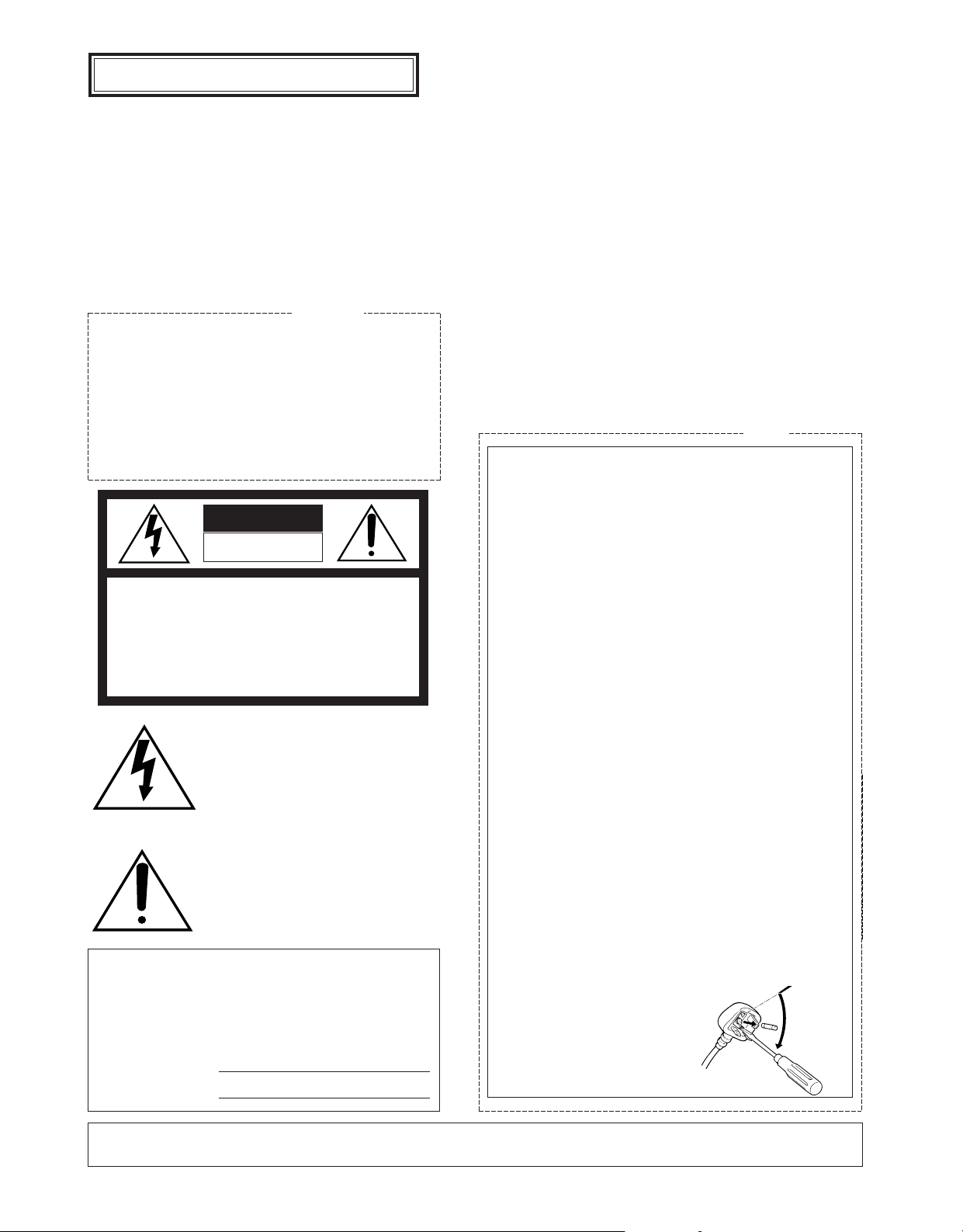
The lightning flash with arrowhead symbol, within an equilateral triangle, is
interned to alert the user to the presence
of uninsulated "dangerous voltage" within
the product's enclosure that may be of
sufficient magnitude to constitute a risk of
electric shock to persons.
The exclamation point within an equilateral triangle is intended to alert the user
to the presence of important operating
and maintenance (servicing) instructions
in the literature accompanying the appliance.
WARNING:
TO PREVENT FIRE OR ELECTRIC SHOCK HAZARD, DO NOT EXPOSE THIS APPLIANCE TO RAIN OR MOIS
TURE.
CAUTION:
TO REDUCE THE RISK OF ELECTRIC SHOCK,
DO NOT REMOVE COVER (OR BACK), NO USER
SERVICEABLE PARTS INSIDE.
REFER SERVICING TO QUALIFIED SERVICE
PERSONNEL.
CAUTION
RISK OF ELECTRIC SHOCK
DO NOT OPEN
For Australia
FOR YOUR SAFETY PLEASE READ THE FOLLOWING TEXT CAREFULLY.
This appliance is supplied with a moulded three pin mains plug for your
safety and convenience.
A 13 amp fuse is fitted in this plug.
Should the fuse need to be replaced please ensure that the replacement
fuse has a rating of 13 amp and that it is approved by ASTA or BSI to
BS1362.
Check for the ASTA mark
H or the BSI mark G on the body of the
fuse.
If the plug contains a removable fuse cover you must ensure that it is
refitted when the fuse is replaced.
If you lose the fuse cover the plug must not be used until a replacement
cover is obtained.
A replacement fuse cover can be purchased from your local Panasonic
Dealer.
IF THE FITTED MOULDED PLUG IS UNSUITABLE FOR THE SOCKET OUTLET IN YOUR HOME THEN THE FUSE SHOULD BE
REMOVED AND THE PLUG CUT OFF AND DISPOSED OF SAFELY.
THERE IS A DANGER OF SEVERE ELECTRICAL SHOCK IF THE
CUT OFF PLUG IS INSERTED INTO ANY 13 AMP SOCKET.
If a new plug is to be fitted please observe the wiring code as shown
below.
If in any doubt please consult a qualified electrician.
WARNING: This apparatus must be earthed.
IMPORTANT
The wires in this mains lead are coloured in accordance with the following code.
Green-and-yellow: Earth
Blue: Neutral
Brown: Live
As the colours of the wire in the mains lead of this appliance may not
correspond with the coloured markings identifying the terminals in your
plug, proceed as follows.
The wire which is coloured green-and-yellow must be connected to
the terminal in the plug which is marked with the letter E or by the earth
symbol
I or coloured green or green-and-yellow.
The wire which is coloured blue must be connected to the terminal in
the plug which is marked with the letter N or coloured black.
The wire which is coloured brown must be connected to the terminal
in the plug which is marked with the letter L or coloured red.
How to replace the fuse
Open the fuse compartment with
a screwdriver and replace the fuse
and fuse cover.
For U.K.
ENGLISH VERSION
CAUTION:
Before attempting to connect or operate this product, please read the label on the bottom.
Page 3

Page 4

CONTENTS
PREFACE ................................................................................................................................................................................ 2
FEATURES .............................................................................................................................................................................. 2
IMPORTANT NOTICES ........................................................................................................................................................... 2
PRECAUTIONS ....................................................................................................................................................................... 2
MAJOR OPERATING CONTROLS AND THEIR FUNCTIONS ................................................................................................. 3
RACK MOUNTING .................................................................................................................................................................. 6
SETTING UP THE MENU ........................................................................................................................................................ 7
A. Setting up MENU 1 OF 3 in MULTIPLEX mode ............................................................................................................... 8
B. Setting up MENU 2 OF 3 in MULTIPLEX mode ............................................................................................................. 10
C. Setting up MENU 3 OF 3 in MULTIPLEX mode ............................................................................................................... 11
A. Setting up MENU 1 OF 3 in MULTISCREEN mode ......................................................................................................... 13
B. Setting up MENU 2 OF 3 in MULTISCREEN mode ......................................................................................................... 14
C. Setting up MENU 3 OF 3 in MULTISCREEN mode ......................................................................................................... 14
OPERATION ........................................................................................................................................................................... 15
MULTIPLEX Mode ............................................................................................................................................................... 15
MULTISCR Mode ................................................................................................................................................................. 20
CONNECTION ........................................................................................................................................................................ 22
SPECIFICATIONS ................................................................................................................................................................... 26
STANDARD ACCESSORIES ................................................................................................................................................... 26
-1-
Wij verklaren als enige aansprakelijke, dat het product waarop deze
verklaring betrekking heeft, voldoet aan de volgende normen of
andere normatiefve dokumenten, overeenkomstig de bepalingen
van Richtlijnen 73/23/EEC en 89/336/EEC.
Vi erklærer os eneansvarlige for, at dette produkt, som denne
deklaration omhandler, er i overensstemmelse med den følgende
standarder eller andre normative dokumenter i følge bestem-
melserne i direktivene 73/23/EEC og 89/336/EEC.
Vi deklarerar härmed värt fulla ansvar för att den produkt till vilken
denna deklaration hänvisar är i överensstämmelse med standard-
dokument, eller andra normativa dokument som framstölls i Direktiv
73/23/EEC och 89/336/EEC.
Ilmoitamme yksinomaisella vastuullamme, että tuote, jota tämä
ilmoitus koskee, noudattaa seuraavia standardeja tai muita ohjeel-
lisia asiakirjoja, jotka noudattavat direktiivien 73/23/EEC ia
89/336/EEC. säädöksiä.
Vi erklærer oss alene ansvarlige for at produktet som denne
erklæringen gjelder for, er i overensstemmelse med følgende
normer eller andre normgivende dokumenter som fælger bestem-
melsene i direktiven 73/23/EEC og 89/336/EEC.
We declare under our sole responsibility that the product to which
this declaration relates is in conformity with the standards or other
normative documents following the provisions of Directives
EEC/73/23 and EEC/89/336.
Nosotros declaramos bajo nuestra única responsabilidad que el
producto a que hace referencia esta declaración està conforme con
las normas u otros documentos normativos siguiendo las estipulaciones de la directivas CEE/73/23 y CEE/89/336.
Noi dichiariamo sotto nostra esclusiva responsabilità che il prodotto
a cui si riferisce la presente dichiarazione risulta conforme ai
seguenti standard o altri documenti normativi conformi alle disposizioni delle direttive CEE/73/23 e CEE/89/336.
Wir erklären in alleiniger Verantwortung, daß das Produkt, auf das
sich diese Erklärung bezieht, mit der folgenden Normen oder normativen Dokumenten übereinstimmt. Gemäß den Bestimmungen
der Richtlinite 73/23/EEC und 89/336/EEC.
Nous déclarons sous notre seule responsabilité que le produit
auquel se référe cette déclaration est conforme aux normes ou
autres documents normatifs conformément aux dispositions de la
directive 73/23/CEE et 89/336/CEE.
ENGLISH
Page 5

-2-
PREF ACE IMPORTANT NOTICES
PRECAUTIONS
The WJ-FS216 Video Multiplexer is designed to pick up
the field signals from video cameras and record the
camera images on a time lapse VTR. The pictures of
up to 16 cameras can be monitored in single, quad or
multi picture mode. Camera/pictures can be called
from the time lapse VTR output by a title added to the
camera picture or by simply pressing the selection button for the respective camera.
FEATURES
The WJ-FS216 Video Multiplexer is designed to pick up
the field signals from video cameras and record the
camera images on a time lapse VTR. Up to 16 cameras
(black & white or colour cameras) can be connected to
the WJ-FS216 regardless of whether the camera signals
are synchronized or not.
The functions of the two available modes, MULTIPLEX
and MULTISCR, are as follows:
• MULTIPLEX mode
1. Monitoring sequential or single (spot) pictures and
simultaneously recording them on the time lapse
VTR.
2. Easy selection of playback picture from the time
lapse VTR and displaying it as a single (spot) or
multi picture (quad, 3x3, or 4x4) by simply pushing
the camera selection button.
The Quad Shift function allows you to shift between
up to four quad pictures (each consisting of 4 pictures).
3. Pauses can be inserted in the pictures reproduced
by the time lapse VTR (STILL ON mode). In multi
picture mode, pauses can also be inserted in any
monitored pictures, and single spot pictures can be
zoomed up to twofold.
• MULTISCR mode
1. You can monitor sequential, single (spot) or multi
pictures (quad, 3x3, or 4x4).
In multi picture mode, all camera pictures are displayed on the multiscreen skipping some frames.
2. You can switch between display patterns (spot,
quad, 3x3, or 4x4) by simply pressing any of the
camera selection buttons 1 to 3.
3. The Quad Shift function allows you to display up to
four quad pictures (each consisting of 4 pictures)
on one screen.
4. You can pause (STILL ON mode) or zoom the playback picture. In multi picture mode, all pictures
monitored can be paused, but only one specified
picture can be zoomed.
• Common to both modes
1. Remote control
2. An alarm beeps to indicate that a cable is disconnected.
3. Memory backup (approx. 72 hours) for menus.
• While playing back the picture of the time lapse
VTR with linear mode, the picture of another channel may be reproduced and break in. In this case,
play back again in normal mode or time lapse
mode.
• This unit does not accept the camera motion detector alarm signal.
• Do not attempt to disassemble the unit. In order to
prevent electrical shock, do not remove screws or
covers. There are no user-serviceable parts inside.
• Do not abuse the unit. Avoid striking, shaking etc. It
could be damaged by improper handling or storage.
• Do not use strong or abrasive detergents when
cleaning the unit body.
• Do not expose the unit to water or moisture, and do
not operate it in wet or humid areas.
• Do not use the unit in an extreme environment
where high temperature or high humidity exists.
• Handle the unit with care.
• Take immediate action if ever the unit does become
wet. Tune the power off and refer servicing to qualified service personnel. Moisture can damage the
unit and also create a danger of electric shock.
• Use the unit under conditions where temperature is
within
−10°C to +50°C (14°F to 122°F), and humidity
is below 90%. When installing the unit in the rack, it
is recommended to install the fan.
• The input power source is 220 - 240 V AC, 50 Hz.
• Refer all installation work to qualified service personnel or system installers.
Page 6
-3-
2. Alarm LED (ALARM)
This LED flashes while the alarm signal is received.
It lights in the following cases:
• When the ALARM/REMOTE connector receives
the alarm reset signal.
• When the alarm reset time specified for AUTO
RESET in MENU 1 OF 3 has elapsed (in multiscreen mode).
To turn off the LED, press the ALARM RESET button.
3. Sequence/Alarm Reset Button
(SEQUENCE/ALARM RESET)
This button activates sequence mode when the
MODE SELECT/CAMERA SELECT switch is in
CAMERA SELECT position.
In alarm condition, this button serves as ALARM
RESET button regardless of the MODE
SELECT/CAMERA SELECT switch position.
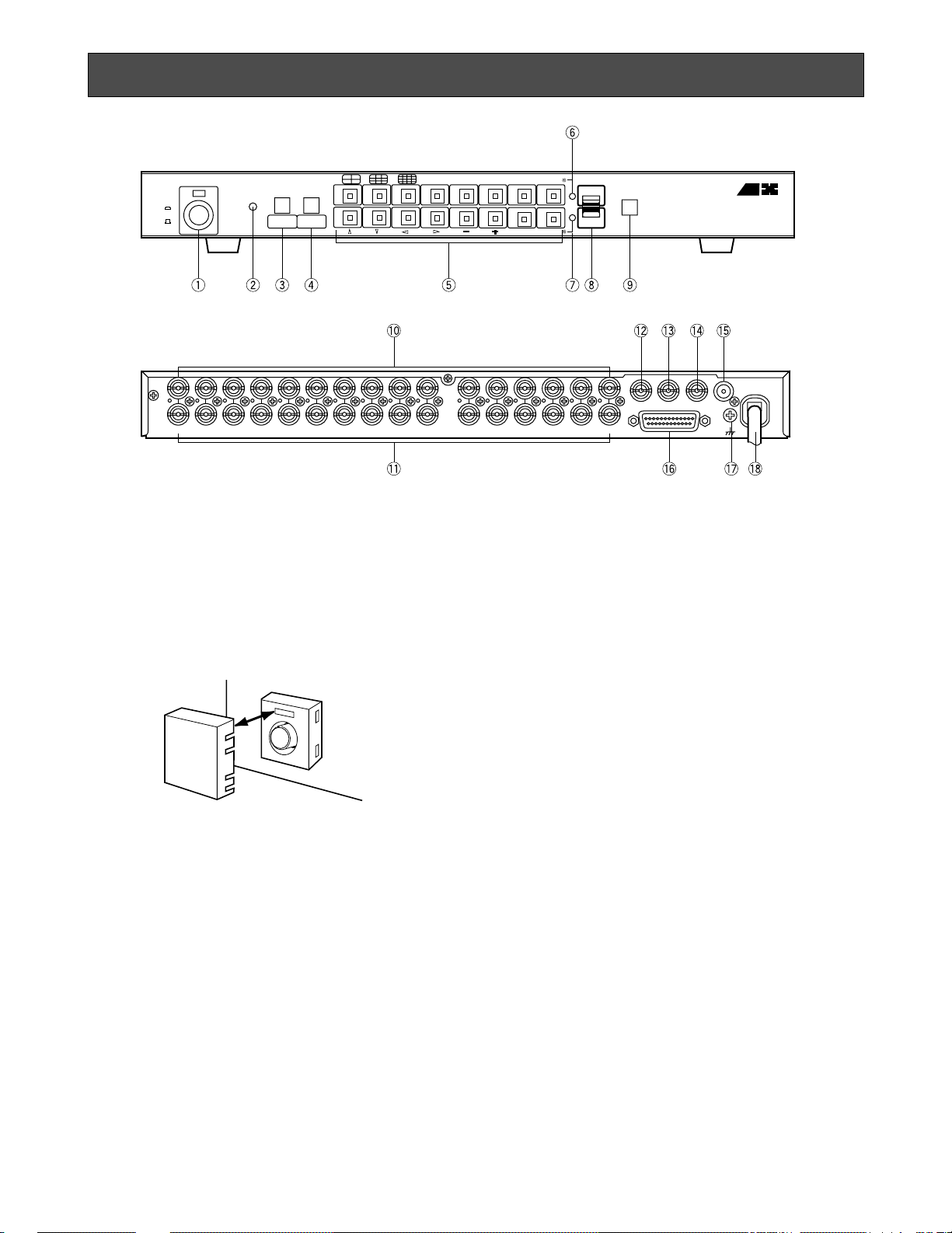
MAJOR OPERATING CONTROLS AND THEIR FUNCTIONS
CAMERA
IN
CAMERA
OUT
PLAY IN MONITOR OUT
ALARM/REMOTE
CAMERA
SW IN
SIGNAL
GND
16 15 14
13
12 11 10 9
8
6
54321
7
16 15 14
13
12 11 10 9 8
6
543217
POWER
ON
OFF
ZOOMALARM
CAMERA
SELECT
MODE
SELECT
MENU
CAMERA/VTR
SET
STILL ON
Digital Video MultiplexerWJ-FS 21 6
SEQENCE
ALARMRESET
MULTI SCREEN
QUAD SHIFT
Panasonic
1234
9101112 13
561478
15 16
REC OUT
• Sequence Button
This button is used to activate the sequence mode.
In this mode, a series of pictures is displayed in
succession on the monitor screen in the order and
for the duration or dwell time you set.
• Alarm Reset Button
This button is used to cancel an active alarm.
Press while the alarm function is activated to reset
the alarm and the unit to the condition before the
alarm function was activated.
4. Zoom/Multiscreen/Quad Shift Button (ZOOM/
MULTISCREEN/QUAD SHIFT)
This button has three functions. The functions
change according to the position of the MODE
SELECT/CAMERA SELECT switch as follows:
When the MODE SELECT/CAMERA SELECT switch
is in CAMERA SELECT position, this button works
as the MULTISCREEN or the QUAD SHIFT button.
When the MODE SELECT/CAMERA SELECT switch
is in MODE SELECT position, this button works as
the ZOOM button.
• MULTISCREEN button
Pressing this button changes the picture (camera picture or playback picture from the time
lapse VTR) to four (quad), 3x3 or 4x4 (multi)
pictures.
• QUAD SHIFT button
Pressing this button when monitoring a quad
picture shifts to another of up to four quad pictures. See page 17 for details.
• ZOOM button
Pressing this button zooms up a specified portion of the monitored picture.
See page 19 or 21 for details.
1. Power ON/OFF Switch (POWER ON/OFF)
This switch is used to turn the power of this unit on
or off. The POWER indicator lights when the power
of this unit is on.
Switch Protector (Standard Accessory)
To prevent that the power of the video multiplexer is turned off accidentally, install the supplied switch protector as shown below.
SWITCH
PROTECTOR
Page 7

-4-
5. Camera Selection Button (1...16, , , ,
CAMERA/VTR,
DD, CC, AA, BB, –, +, SET, STILL
ON)
When the MODE SELECT/CAMERA SELECT switch
is in CAMERA SELECT position, these buttons can
be used to select the desired camera. The LED in
the button lights to indicate the number of the
selected camera.
Except for buttons 4, 5, 6 and 7, the function of
these buttons changes when the MODE SELECT/
CAMERA SELECT switch is set to MODE SELECT
position. The functions of each button are as follows:
Button No.1 ( )
When the MULTIPLEX mode is selected, the playback picture is displayed as a quad picture.
When the MULTISCR mode is selected, the camera
picture is displayed as a quad picture.
Button No.2 ( )
When MULTIPLEX mode is selected, the monitor
screen is divided into nine fields for displaying
playback pictures.
When MULTISCR mode is selected, the screen is
divided into nine fields for displaying camera pictures.
Button No.3 ( )
When MULTIPLEX mode is selected, the monitor
screen is divided into sixteen fields for displaying
playback pictures.
When MULTISCR mode is selected, the screen is
divided into sixteen fields for displaying camera
pictures.
Button No.8 (CAMERA / VTR)
This button is used to select the camera picture or
playback picture to be displayed on the monitor.
While the playback picture is displayed, the CAMERA/VTR indicator lights to indicate that VTR is
selected.
Button No.9 (DD)
Moves the “+” sign (zoom cursor) upward.
Use this button to move the cursor on the menu.
Button No.10 (CC)
Moves the “+” sign (zoom cursor) downward.
Use this button to move the cursor on the menu.
Button No.11 (AA)
Moves the “+” sign (zoom cursor) to the left.
Use this button to move the cursor on the menu.
Button No.12 (BB)
Moves the “+” sign (zoom cursor) to the right.
Use this button to move the cursor on the menu.
Button No.13 (–)
Moves the character selection cursor in reverse
alphabetical order.
Button No.14 (+)
Moves the character selection cursor in alphabetical order.
Button No.15 (SET)
This button is used as the SET button in setting procedures.
Button No.16 (STILL ON)
This button is used to pause the picture on the
screen and monitor the still picture (STILL ON
mode).
6. CAMERA/VTR Indicator
While this indicator is lit, the playback picture can
be displayed on the monitor.
7. STILL ON indicator
While this indicator is lit, the picture can be made
still by pressing one of the camera selection buttons.
8. MODE SELECT/CAMERA SELECT Switch
This switch is used to change the functions of the
buttons on the front panel.
When this switch is positioned at CAMERA SELECT,
the buttons operate as indicated by the printed button name in the gray square.
When this switch is positioned at MODE SELECT,
the buttons operate normally as indicated by the
printed button name.
9. Menu button (MENU)
This button is used to display the setup menu.
Pressing this button for 2 seconds or longer will display the menu on the monitor screen. To return to
monitoring, press this button again for 2 seconds or
longer.
10. Camera Input Connectors
These connectors input the composite video signal
from the cameras.
Note:
If the video signal is interrupted due to a cable
disconnection, for example, the message
“CHXXLOSS” is displayed and the buzzer
beeps. Check that the connections are correct
and firm, then input the video signal again or
press the SEQUENCE/ALARM RESET button.
This stops the buzzer and resets the alarm and
the unit to the condition before the video signal
was interrupted.
Caution:
The picture may be disturbed when switching
non-synchronized camera signals. This can be
avoided by synchronizing the camera signals.
11. Camera Output Connectors (CAMERA OUT)
The signals from the input cameras are looped
through at these connectors. Connecting a coaxial
cable will automatically select high impedance
video loop.
12. Playback Input Connector (PLAY IN)
The playback signal from the time lapse VTR is supplied to this connector. This connector works only
when MULTIPLEX mode is selected.
Page 8

-5-
13. Recording Output Connector (REC OUT)
This connector supplies the recording signal for the
time lapse VTR.
Caution:
In MULTIPLEX mode, the unit adds codes to
video signals during vertical blanking while they
are recorded on the VTR. This is the reason
why video signals with a certain code are not
recordable during vertical blanking.
14. Monitor Output Connector (MONITOR OUT)
This connector supplies a composite video signal
for monitoring. Sequential picture, time lapse VTR
playback pictures and the menus can be displayed
on a connected monitor.
15. Camera Switching Signal Input Connector
(CAMERA SW IN)
The camera switching signal from the time lapse
VTR is supplied to this connector. This connector
works only when the MULTIPLEX mode is selected.
Note:
When REC MODE is set to T/L but no camera
switching signal is supplied, time lapse recording will not work properly.
16. ALARM/REMOTE Connector
This connector is used for remote controlling. You
can control the following functions:
• Alarm Output
• Recover Input
• MULTISCREEN
• SEQ
• Receiving the alarm input signal at the camera
site, or the remote input signal for the camera
selection buttons.
17. Ground Terminal
18. Power Cord
Page 9
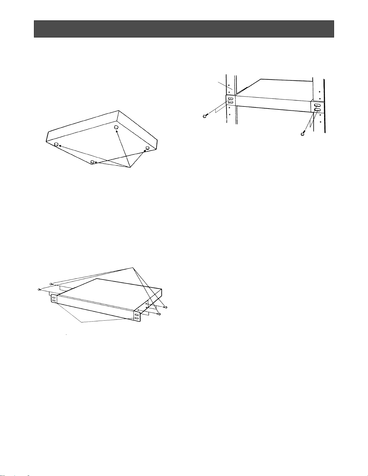
-6-
To install the WJ-FS216 Video Multiplexer in an EIA 19inch rack, use the rack mounting brackets (provided)
and eight screws (provided, M3x10).
1. Turn off the power of the unit.
2. Remove the four screws fixing the rubber legs and
remove the four rubber legs from the unit.
Remove four rubber legs.
3. Attach the rack mounting brackets on both sides
and fix them with eight screws (provided).
Fix the rack mounting brackets
4. Install the unit in the rack with four screws (to be
procured locally).
Cautions:
1. Leave one space free both above and below the
unit, or install a cooling fan in the rack.
2. If the rack is subject to vibrations, secure the rear of
the unit to the rack using additional rack mounting
brackets (to be procured locally).
Eight screws (Provided)
EIA 19”
rack
RACK MOUNTING
Page 10
-7-
• Before the settings
1. Confirm that the cameras and peripherals are connected correctly and firmly.
2. Turn on the power of this unit and connected
peripherals.
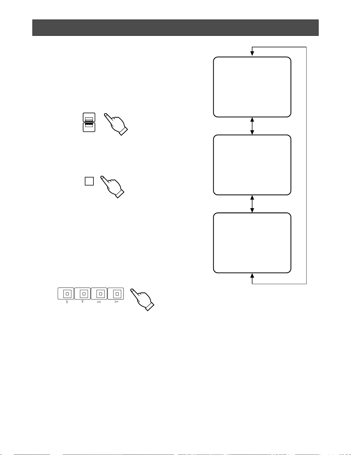
1. Displaying the Menus
1. Set the MODE SELECT/CAMERA SELECT switch to
MODE SELECT position.
CAMERA
SELECT
MODE
SELECT
2. Press the MENU button for 2 seconds. MENU 1 OF
3 appears on the monitor.
2. Selecting the system mode
This unit can be adapted to specific user needs.
Before performing other settings, follow the steps
below to select the system mode that best meets
your requirements.
1. After displaying MENU 1 OF 3, use buttons 9 - 12
(DD, CC, AA, BB) to display MENU 3 OF 3. The func-
tions of these buttons in the menu are as follows:
2. Move the cursor to SYSTEM MODE by pressing button 9 (DD) or 10 (CC).
3. Select MULTIPLEX or MULTISCR by pressing button 13 (−) or 14 (+).
MULTIPLEX:
Select this mode to monitor the camera pictures or
playback pictures.
In MULTIPLEX mode you can perform the following
monitoring operations:
1. Camera picture
• Single spot picture
• Single spot picture sequence
2. Playback picture of the time lapse VTR
• Single spot picture
• Single spot picture sequence
• Multi spot picture
• Quad picture sequence
• Still single spot picture
• Still multi spot picture
• Single spot picture zoom
* MENU 1 OF 3 *
DYNAMIC REC OFF
ALARM BUZZER 2S
ALARM OUTPUT 2S
REC MODE 4FIELDS
* MENU 2 OF 3 *
TITLE SETUP *
TITLE POSITION *
TITLE DISPLAY ON
STILL/ALARM DISP ON
* MENU 3 OF 3 *
BORDER WHITE
AUTO SKIP OFF
SEQUENCE SETUP *
START SCREEN 1-SEQ
SYSTEM MODE MULTIPLEX
MENU
910
11
12
• Button 9 (DD)
Moves the cursor upward. Pressing this button
when the cursor is on the first menu item displays
the previous menu.
• Button 10 (CC)
Moves the cursor downward. Pressing this button
when the cursor is on the last menu item displays
the next menu.
• Button 11 (AA)
Moves the cursor to the left or upward. Pressing
this button when the cursor is on the first menu item
displays the previous menu.
• Button 12 (BB)
Moves the cursor to the right or downward.
Pressing this button when the cursor is on the last
menu item displays the next menu.
SETTING UP THE MENU
Page 11

-8-
MULTISCR:
Select this mode to monitor the camera pictures.
In MULTISCR mode you can perform the following
monitoring operations:
1. Camera picture
• Single spot picture
• Multi spot picture
• Single spot picture sequence
• Quad picture sequence
• Still multi spot picture
• Multi spot picture zoom
The menu content is different depending on the
selected mode. (Compare MENU 1 OF 3 for MULTIPLEX and MULTISCR mode below.) This is
described in more detail on the following pages.
* MENU 1 OF 3 *
DYNAMIC REC OFF
ALARM BUZZER 2S
ALARM OUTPUT 2S
REC MODE 4FIELDS
* MENU 1 OF 3 *
AUTO RESET 60S
ALARM BUZZER 2S
ALARM OUTPUT 2S
MULTISCR CH SET *
MULTIPLEX mode
MULTISCR mode
Blinking
Blinking
4. Press the MENU button to return to monitoring.
• How to Operate the Menus
To select the desired item, press buttons 9-12 (DD,
CC, AA, BB). Each time you press a button, the cursor
moves to the parameter of the selected item.
To set or select the desired parameter of the selected item, press button 13 (−) or 14 (+).
Note:
Some items have a submenu (for example,
TITLE SETUP in MENU 2 OF 3). To make settings in a submenu, press button 15 (SET).
A. Setting up MENU 1 OF 3 in
MULTIPLEX mode
The content of MENU 1 OF 3 in MULTIPLEX mode
is as shown below.
* MENU 1 OF 3 *
DYNAMIC REC OFF
ALARM BUZZER 2S
ALARM OUTPUT 2S
REC MODE 4FIELDS
1. DYNAMIC REC
When ON is selected for DYNAMIC REC, the
camera picture of a channel that receives an alarm
signal is recorded with more fields than normal. If
the alarm signal is received by multiple channels,
the pictures of all these channels are recorded.
1. Move the cursor to the DYNAMIC REC parameter.
910
11
12
2. Select ON or OFF.
ON: The video signal of the channel that receives
the alarm signal is recorded with more fields
than normal. If the alarm signal is received by
multiple channels, the pictures of all these
channels are recorded.
OFF: The video at field rate are recorded from
channels number 1 to 16 regardless of any
channels receiving the alarm signal.
The factory setting is OFF.
• If you do not change any other parameters, press
the MENU button for 2 seconds. The setup menu is
closed and the display returns to the monitoring
picture.
Before turning the power off, make sure to finalize
your settings by pressing the MENU button.
Otherwise the new settings will not be stored and
the previous settings remain in effect. Turn the
power off after the monitoring picture appears on
the display.
Page 12

-9-
2. ALARM BUZZER
The buzzer beeps when this unit receives the alarm
signal. You can adjust the buzzer time between 1
and 60 seconds by changing the ALARM BUZZER
parameter.
1. Move the cursor to the ALARM BUZZER parameter.
2. Select the buzzer time.
OFF: The alarm buzzer does not beep when the
alarm signal is received.
1-30, 60S: The buzzer keeps on beeping for the
duration you set. The letter “S” stands for seconds.
The factory setting is 2S.
* MENU 1 OF 3 *
DYNAMIC REC OFF
ALARM BUZZER 2S
ALARM OUTPUT 2S
REC MODE 4FIELDS
2. Select the duration the alarm signal is output.
1-30, 60S: The alarm signal is output for the dura-
tion you set. The letter “S” stands for seconds.
The factory setting is 2S.
3. ALARM OUTPUT
When alarm is received, the alarm signal is supplied to the other device through the
ALARM/REMOTE connector. You can adjust the
duration the alarm signal is output between 1 and
60 seconds.
1. Move the cursor to the ALARM OUTPUT parameter.
* MENU 1 OF 3 *
DYNAMIC REC OFF
ALARM BUZZER 2S
ALARM OUTPUT 2S
REC MODE 4FIELDS
2. Select the recording mode.
4-255 FIELDS: The output signal to be recorded on
the VTR is switched each time after the number
of fields you have set.
T/L: The recording output signal is supplied to the
VTR for time lapse recording.
The factory setting is 4 FIELDS.
Note:
When T/L is selected and no camera switching
signal supplied, there will be no correct time
lapse recording. In this case, either supply the
camera switching signal or select 4 - 255 fields
in REC mode for normal recording.
4. REC MODE
The recording mode can be set to 4-255 fields or
time lapse recording.
1. Move the cursor to the REC MODE parameter.
* MENU 1 OF 3 *
DYNAMIC REC OFF
ALARM BUZZER 2S
ALARM OUTPUT 2S
REC MODE 4FIELDS
Page 13

-10-
1. Move the cursor to SETUP in TITLE SETUP.
B. Setting up MENU 2 OF 3 in
MULTIPLEX mode
The context of MENU 2 OF 3 will not change if the
SYSTEM MODE parameter in MENU 3 OF 3 is
changed.
An example is shown below.
1. TITLE SETUP
A title consisting of up to 8 alphanumeric characters
can be displayed on the monitor.
* MENU 2 OF 3 *
TITLE SETUP *
TITLE POSITION *
TITLE DISPLAY ON
STILL/ALARM DISP ON
* MENU 2 OF 3 *
TITLE SETUP *
TITLE POSITION *
TITLE DISPLAY ON
STILL/ALARM DISP ON
** TITLE **
1........ 9........
2........ 10........
3........ 11........
4........ 12........
5........ 13........
6........ 14........
7........ 15........
8........ 16........
2. Press button 15 (SET). The TITLE menu appears on
the monitor.
3. Move the cursor to the channel number whose title
is to be edited by pressing buttons 9-12 (DD, CC, AA,
BB).
4. Select the first character for the title by pressing
button 13 (−) or 14 (+).
Characters for the title can be selected from the following list:
5. After selecting the first character, press button 12
(BB). Then select the second character.
6. Repeat steps 3 to 5 above to complete the title.
7. Repeat steps 3 to 6 to edit the other channels.
8. Press button 15 (SET) to finalize the character
selection. The title is set, and the display returns to
MENU 2 OF 3.
To erase a specific character
1. Select a character to be erased.
2. Select “•” (space mark) to erase the character.
To erase the title of a specific channel
1. Move the cursor to the channel number whose title
is to be erased.
2. Press buttons 13 (−) and 14 (+) simultaneously.
2. TITLE POSITION
You can select the position on the monitor where
you want the title to be displayed.
1. Move the cursor to POSITION in TITLE POSITION.
ABCDEFGHIJKLM
NOPQRSTUVWXYZДЬЦЖСЕШ
0123456789
←→
=?’”#&()*+,
-·/:;.(space mark)
2. Press button 15 (SET). The TITLE POSITION setting
is on stand by.
* MENU 2 OF 3 *
TITLE SETUP *
TITLE POSITION *
TITLE DISPLAY ON
STILL/ALARM DISP ON
12
34567
3. Select the position where the title is to be displayed
by pressing button 11 (AA) or 12(BB). You can
select any of the 7 positions shown in the diagram
above.
4. Press button 15 (SET) to finalize the title position.
The title position is set, and the display returns to
MENU 2 OF 3.
Note:
All channel titles will be displayed in the same
position.
You cannot specify a different position for each
title.
Page 14

-11-
3. TITLE DISPLAY
This parameter lets you decide whether or not to
have the title displayed.
1. Move the cursor to the TITLE DISPLAY parameter.
* MENU 2 OF 3 *
TITLE SETUP *
TITLE POSITION *
TITLE DISPLAY ON
STILL/ALARM DISP ON
2. Select ON or OFF.
ON: Title display
OFF: No title display
The factory setting is ON.
4. STILL/ALARM DISP
This parameter lets you decide whether or not to
have the word “STILL” displayed when a picture is
paused by pressing button 16 (STILL ON), or the
word “ALARM” when the unit receives the alarm
signal.
1. Move the cursor to the STILL/ALARM DISP parameter.
2. Select ON or OFF.
ON: “STILL” and “ALARM” are displayed.
OFF: “STILL” and “ALARM” are not displayed.
The factory setting is ON.
* MENU 2 OF 3 *
TITLE SETUP *
TITLE POSITION *
TITLE DISPLAY ON
STILL/ALARM DISP ON
1. BORDER
This parameter lets you select the colour of the borders that divide the screen.
1. Move the cursor to the BORDER parameter.
2. Select the colour of the borders.
OFF: No borders
BLACK: Black borders
GRAY: Grey (Gray) borders
WHITE: White borders
The factory setting is WHITE.
2. AUTO SKIP
This parameter lets you select automatic skipping of
channels to which no camera is connected.
1. Move the cursor to the AUTO SKIP parameter.
C. Setting up MENU 3 OF 3 in
MULTIPLEX mode
The content of MENU 3 OF 3 in MULTIPLEX mode
is as shown below.
* MENU 3 OF 3 *
BORDER WHITE
AUTO SKIP OFF
SEQUENCE SETUP *
START SCREEN 1-SEQ
SYSTEM MODE MULTIPLEX
* MENU 3 OF 3 *
BORDER WHITE
AUTO SKIP OFF
SEQUENCE SETUP *
START SCREEN 1-SEQ
SYSTEM MODE MULTIPLEX
* MENU 3 OF 3 *
BORDER WHITE
AUTO SKIP OFF
SEQUENCE SETUP *
START SCREEN 1-SEQ
SYSTEM MODE MULTIPLEX
2. Select ON or OFF.
ON: Channels to which no camera is connected are
skipped.
OFF: No channels are skipped.
The factory setting is OFF.
Page 15

-12-
2. Press button 15 (SET). The SEQUENCE menu
appears on the monitor.
3. Move the cursor to the sequence number by pressing buttons 9-12 (DD, CC, AA, BB).
4. Select the channel by pressing button 13 (−) or 14
(+).
5. Move the cursor to the dwell time by pressing button 12 (BB).
6. Select the desired dwell time by pressing button 13
(−) or 14 (+).
If you select OFF for the dwell time, the selected
channel is automatically skipped.
7. Repeat steps 3 to 6 to determine the sequential
order and dwell time.
8. Press button 15 (SET) to finalize the sequential
order. The display returns to MENU 3 OF 3.
Note: When monitoring a quad picture, the dwell time
indicated for sequence numbers 1-4 refers to that of
the four quad pictures.
4. ST ART SCREEN
This parameter lets you select a display pattern for
your startup screen. When the power is turned on,
the picture is displayed in the selected pattern.
1. Move the cursor to the START SCREEN parameter.
2. Select FULL or 1-SEQ.
FULL: A single picture is displayed.
1-SEQ: A sequence of a single picture is displayed.
The factory setting is 1-SEQ.
5. SYSTEM MODE
See “Selecting the system mode” on page 6 for settings and procedures.
* MENU 3 OF 3 *
BORDER WHITE
AUTO SKIP OFF
SEQUENCE SETUP *
START SCREEN 1-SEQ
SYSTEM MODE MULTIPLEX
** SEQUENCE **
1 1CH 2S 9 9CH 2S
2 2CH 2S 10 10CH 2S
3 3CH 2S 11 11CH 2S
4 4CH 2S 12 12CH 2S
5 5CH 2S 13 13CH 2S
6 6CH 2S 14 14CH 2S
7 7CH 2S 15 15CH 2S
8 8CH 2S 16 16CH 2S
Sequence Number Channel Dwell Time
* MENU 3 OF 3 *
BORDER WHITE
AUTO SKIP OFF
SEQUENCE SETUP *
START SCREEN 1-SEQ
SYSTEM MODE MULTIPLEX
3. SEQUENCE SETUP
This parameter lets you set the sequential order and
dwell time for camera switching.
1. Move the cursor to SEQUENCE SETUP.
Page 16

-13-
* MENU 1 OF 3 *
AUTO RESET 60S
ALARM BUZZER 2S
ALARM OUTPUT 2S
MULTISCR CH SET *
* MENU 1 OF 3 *
AUTO RESET 60S
ALARM BUZZER 2S
ALARM OUTPUT 2S
MULTISCR CH SET *
** CH SET **
1 1CH 9 9CH
2 2CH 10 10CH
3 3CH 11 11CH
4 4CH 12 12CH
5 5CH 13 13CH
6 6CH 14 14CH
7 7CH 15 15CH
8 8CH 16 16CH
** CH SET **
1 1CH 9 9CH
2 2CH
3 3CH
4 4CH
5 5CH
6 6CH
7 7CH
8 8CH
21
2. Select the recover time.
OFF: The alarm condition is maintained until the
ALARM RESET button on the front panel is
pressed or the alarm recover signal from the
time lapse VTR is supplied to the ALARM/
REMOTE connector.
1-30, 60S: The alarm condition is maintained for the
length of the recover time you set. The letter
“S” stands for seconds.
The factory setting is 60S.
2. ALARM BUZZER
This item is the same as in MENU 1 OF 3 in the
MULTIPLEX mode. See page 9 for the settings and
procedures.
3. ALARM OUTPUT
This item is the same as in MENU 1 OF 3 in the
MULTIPLEX mode. See page 9 for the settings and
procedures.
4. MUL TISCR CH SET
This parameter lets you assign the channel to be
displayed to a specific divided screen.
1. Move the cursor to CH SET in MULTISCR CH SET.
2. Press button 15 (SET). The CH SET menu appears
on the monitor.
3. Press button 1 ( ) or 2 ( ) to select the CH
SET menu for MULTISCREEN.
Button 1: Displays the CH SET menu for quad and
4x4 multiscreen.
Button 2: Displays the CH SET menu for 3x3 multi-
screen.
4. Move the cursor to the number of the divided
screen by pressing buttons 9-12 (DD, CC, AA, BB).
5. Select the channel number to be assigned to the
selected divided screen by pressing button 13 (−)
or 14 (+).
6. Repeat steps 4 and 5 above to assign the other
channels to the divided screens.
7. Press button 15 (SET) to finalize channel assignment. The display returns to MENU 1 OF 3.
A. Setting up MENU 1 OF 3 in
MULTISCREEN mode
1. AUTO RESET
This parameter lets you set the time until the unit
recovers after receiving the alarm signal.
1. Move the cursor to the AUTO RESET parameter.
Page 17

-14-
B. Setting up MENU 2 OF 3 in
MULTISCREEN mode
MENU 2 OF 3 in the MULTISCR mode is the same
as in the MULTIPLEX mode. See page 10 for the
settings and procedures of the MENU 2 OF 3.
C. Setting up MENU 3 OF 3 in
MULTISCREEN mode
1. BORDER
This item is the same as in MENU 3 OF 3 in the
MULTIPLEX mode. See page 11 for the settings
and procedures.
2. AUTO SKIP
This item is the same as in MENU 3 OF 3 in the
MULTIPLEX mode. See page 11 for the settings
and procedures.
3. SEQUENCE SETUP
This item is the same as in MENU 3 OF 3 in the
MULTIPLEX mode. See page 12 for the settings
and procedures.
4. ST ART SCREEN
This item is the same as in MENU 3 OF 3 in MULTIPLEX mode, although the parameters are different.
1. Move the cursor to the START SCREEN parameter.
2. Select a display pattern for your startup screen.
FULL: A single spot picture is displayed.
QUAD: Four pictures are displayed on a screen
divided into four segments.
3x3: Nine camera pictures are displayed on a
screen divided into nine segments.
4x4: Sixteen camera pictures are displayed on
a screen divided into sixteen segments.
1-SEQ: A sequence of a single spot picture is
displayed.
4-SEQ: Sequences of pictures from four cam-
eras are displayed on a screen divided into
four segments.
5. SYSTEM MODE
See “Selecting the system mode” on page 7 for settings and procedures.
Page 18

A. Single Spot Picture
1. Set the MODE SELECT/CAMERA SELECT switch to
CAMERA SELECT.
2. Press one of the camera selection buttons for display on the monitor.
The LED on the selected button lights and the
selected camera picture appears on the monitor.
B. Single Spot Picture Sequences
1. Set the MODE SELECT / CAMERA SELECT switch
to CAMERA SELECT.
2. Press the SEQUENCE / ALARM RESET button.
A sequence of single pictures is displayed in the
order and dwell time selected for the SEQUENCE
SETUP parameter in MENU 3 OF 3.
-15-
Before starting operation, set up the items in MENU 1-3
OF 3.
Set SYSTEM MODE in MENU 3 OF 3 to MULTIPLEX or
MULTISCR depending on your specific needs.
MULTIPLEX Mode
Select this mode to monitor camera pictures or playback pictures.
The operations enabled in MULTIPLEX mode are
described below.
■ Monitoring the Camera Picture
Caution: Set the time lapse VTR to the stop mode or
recording mode.
1. Set the MODE SELECT/CAMERA SELECT switch to
MODE SELECT.
2. Press button 8 (CAMERA/VTR). The CAMERA / VTR
indicator goes off.
3. Press button 16 (STILL ON). The STILL ON indicator
goes off.
CAMERA/VTR
8
STILL ON
16
ENTRANCE
Camera Picture
OPERATION
3. To cancel the sequence, press the desired camera
selection button.
The selected camera picture appears in spot on the
monitor.
MODE
SELECT
CAMERA
SELECT
Example of single spot picture sequence
Camera 3 Picture
Camera 6 Picture
Page 19

■ Recording on the Time Lapse VTR
Confirm the REC MODE parameter. See page 9 for
details.
Note: When T/L is selected but no camera switching
signal is supplied, time lapse recording will not
work properly. In this case, supply the camera
switching signal or set REC MODE to 4-255 FIELDS
for normal recording.
■ Monitoring the Playback Picture
Caution:
Set the time lapse VTR to the playback mode.
Recorded tapes should be played back in NORMAL or TIME LAPSE for the time mode.
Notes:
• This unit does not reproduce a clear picture in
reverse playback.
• The playback picture may be skewed (horizontally distorted) under certain circumstances,
but this does not indicate a malfunction.
• The picture or title may vibrate vertically
because they are recorded at field rate, but
this does not indicate a malfunction.
• Depending on the condition of the video
heads, the picture of a channel other than the
selected one may be displayed. If this occurs
frequently, adjust the tracking or slow-tracking
of the VTR. This usually eliminates the problem.
• The size of pictures displayed in quad format is
smaller than in single picture format, which
makes the titles hard to read. Select single
picture (spot) to make titles easier to read.
• While playing back a tape in forward or reverse
search, or a tape that has been recorded in
MULTISCR mode, the looped through video
may appear on the monitor.
• Playing back in linear mode (L12H, L18H,
L24H) may produce noise or the picture of the
other channel is reproduced on the monitor in
any recording mode of the time lapse VTR. In
this case, play back in normal mode (3H) or
time lapse mode.
-16-
ENTRANCE
Playback Picture
A. Single Spot Picture
1. Operate the VTR in playback mode.
2. Set the MODE SELECT / CAMERA SELECT switch
to MODE SELECT.
3. Press button 8 (CAMERA / VTR). The CAMERA /
VTR indicator lights.
4. Set the MODE SELECT / CAMERA SELECT switch
to CAMERA SELECT.
5. Press one of the camera selection buttons to display the desired playback picture on the monitor.
The LED on that button lights up, and the selected
playback picture appears on the monitor.
CAMERA/VTR
8
Page 20

-17-
B. Multi Spot Picture
First select a display pattern.
1. Operate the VTR in playback mode.
2. Set the MODE SELECT/CAMERA SELECT switch to
MODE SELECT.
3. Press button 8 (CAMERA/VTR).
The CAMERA/VTR indicator lights.
4. Set the MODE SELECT/CAMERA SELECT switch to
CAMERA SELECT.
5. Press the ZOOM/MULTISCREEN/QUAD SHIFT button. The multi spot playback picture appears on the
monitor screen.
6. Set the MODE SELECT/CAMERA SELECT switch to
MODE SELECT.
7. Press button 1 ( ), 2 ( ), or 3 ( ) to select
multiscreen pattern (quad, 3x3, or 4x4).
Note: The channel assignment is as shown in the
following diagrams.
Quad
3 x 3
4 x 4
12
34
123
456
789
1256
3478
9 101314
11 12 15 16
12
34
56
78
910
11 12
13 14
15 16
Quad Shift
The LEDs on the camera selection buttons light to
indicate the channels now displayed on the monitor
screen.
• Quad Shift
When you monitor the quad picture while the MODE
SELECT/CAMERA SELECT switch is set to
CAMERA SELECT, the quad picture will be
switched to another quad picture by pressing the
ZOOM/MULTISCREEN/QUAD SHIFT button.
Note:
The quad picture is skipped to another quad
picture if there is no picture in the next quad
picture.
ZOOM
MULTI SCREEN
QUAD SHIFT
123
Page 21

-18-
Playback Picture
of CH 1
Playback Picture
of CH 2
Playback Picture
of CH 3
Playback Picture
of CH 4
Playback Picture
of CH 5
Playback Picture
of CH 6
Playback Picture
of CH 7
Playback Picture
of CH 8
Example of quad
playback picture sequence
C. Single Spot or Quad Playback Picture
Sequences
1. Repeat procedures A (Single Spot Picture) to monitor a single spot playback picture or procedures B
(Multi Spot Picture) to monitor quad playback pictures.
Note: To monitor quad multi spot pictures, press
button 1 ( ). Sequential 3x3 and 4x4 playback pictures are not available.
2. Press the SEQUENCE/ALARM RESET button for
sequential display of playback pictures.
Note: Sequential pictures appear in the last select-
ed mode.
Sequential single spot pictures are displayed
on a single picture screen, and sequential quad
pictures on a quad screen.
Playback Picture of CH 3
Playback Picture of CH 6
Example of single spot
playback picture sequence
3. To cancel sequential picture display, press the
desired camera selection button.
The selected playback picture appears on the single picture screen of the monitor.
SEQENCE
ALARM RESET
D. Still Playback Picture
1. Repeat procedures A (Single Spot Picture) or procedures B (Multi Spot Picture) to monitor playback
pictures.
2. Set the MODE SELECT/CAMERA SELECT switch to
MODE SELECT.
3. Press button 16 (STILL ON). The STILL ON indicator
lights.
4. Set the MODE SELECT/CAMERA SELECT switch to
CAMERA SELECT.
5. Press one of the camera selection buttons whose
indicator is lit.
The LED on the pressed button starts blinking, and
the picture corresponding to that button appears
still on the monitor.
The word STILL appears blinking on the monitor
screen.
STILL ON
16
ENTRANCE
Normal Playback Picture
STILL
Still Picture (The word " STILL" blinks)
Normal Playback Picture
ENTRANCE
Still Picture (The word "STILL" blinks)
STILL
Page 22

-19-
Note: Two or more pictures on the monitor can be
selected in multi picture mode.
6. Press the camera selection button whose indicator
is blinking.
The selected picture is displayed again for normal
monitoring.
7. To release STILL ON mode, set the MODE SELECT/
CAMERA SELECT switch to MODE SELECT, then
press button 16 (STILL ON).
The STILL ON indicator goes out.
Notes:
• If you press the camera selection button for a camera whose picture is not displayed on the monitor
screen, the operation is ignored.
• The word “STILL” is not displayed if STILL/ALARM
DISP in MENU 2 OF 3 is set to OFF.
• While the still picture is displayed, the VTR keeps
playing the playback picture.
E. Single Spot Picture Zoom
The following function is available in single spot picture mode only.
1. Repeat procedures A (Single Spot Picture) to monitor the playback picture.
2. Set the MODE SELECT/CAMERA SELECT switch to
CAMERA SELECT.
3. Press the ZOOM/MULTISCREEN/QUAD SHIFT
button.
The “+” sign appears in the picture.
Note: The “+” sign disappears if no operation is
performed within approx. 5 seconds.
4. Press button 14 (+) to zoom in, or button 13 (–) to
zoom out.
Notes:
• Each time button 14 (+) is pressed, the picture
is zoomed in. Zooming stops when it reaches
the maximum level.
• The picture cannot be zoomed out to be smaller than the original size by pressing button 13
(–).
5. To move the picture, press buttons 9 - 12 (DD, CC,
AA, BB). The zoomed picture will move up, down,
left, or right depending on the button pressed.
The picture will stop at the edge of the monitor
screen.
Normal Playback Picture
Playback Picture with the "+" sign
Zoomed Playback Picture
ENTRANCE
Notes:
• In monitoring single spot playback pictures, only
one zoom level is available.
• The title in the picture disappears when the
ZOOM/MULTISCREEN/QUAD SHIFT button is
pressed. The title remains off the screen even after
the “+”
• sign disappears.
To call the title back on the screen, quit the zoom
function and operate another function.
Page 23

-20-
MULTISCR Mode
Select this mode to monitor the camera pictures.
Selection of MULTISCR mode permits the following
operations.
Monitoring the camera picture
A. Single Spot Picture
Proceed as described in “Monitoring the Camera
Picture, A. Single Spot Picture” on page 15.
B. Multi Spot Picture
1. Set the MODE SELECT/CAMERA SELECT switch to
CAMERA SELECT.
2. Press the ZOOM/MULTISCREEN/QUAD SHIFT button. The multiscreen appears on the monitor.
3. Set the MODE SELECT/CAMERA SELECT switch to
MODE SELECT.
4. Press button 1 ( ), 2 ( ), or 3 ( ) to select
multiscreen pattern (quad, 3x3, or 4x4).
Notes:
• Some frames are skipped as the picture segments are displayed.
• Multi spot pictures being monitored may sometimes vibrate vertically, but this does not indicate a malfunction.
• Quad shift is available by pressing the ZOOM/
MULTISCREEN/QUAD SHIFT button. Refer to
page 17 for more details.
Quad
3 x 3
4 x 4
12
34
123
456
789
1256
3478
9 101314
11 12 15 16
C. Single Spot or Quad Picture Sequences
You can monitor sequential spot pictures or quad
pictures. First select a display pattern.
To monitor sequential single spot pictures, take the
same steps as described in procedures B for
“Single Spot Picture Sequences of Monitoring
Camera Pictures“ on page 15.
To monitor sequential quad pictures, proceed as
described in the following procedures.
1. Take steps 1 to 3 of Procedures B for Multi Spot
Pictures.
2. Press button 1 ( ) to select quad pictures.
3. Press the SEQUENCE/ALARM RESET button. The
quad pictures appear sequentially in the order of
dwell times set in the SEQUENCE SETUP in MENU
3 OF 3.
Camera 1
Picture
Camera 2
Picture
Camera 5
Picture
Camera 6
Picture
Example of quad picture sequence
Camera 8
Picture
Camera 10
Picture
Camera 12
Picture
Camera 16
Picture
4. To cancel sequential picture display, press the
desired camera selection button. The selected
camera picture appears on the single picture
screen of the monitor.
Page 24

-21-
Notes:
• If you press the camera selection button for a
camera whose picture is not displayed on the
monitor screen, the operation is ignored.
• The word “STILL” is not displayed if STILL/
ALARM DISP in MENU 2 OF 3 is set to OFF.
D. Still Multi Spot Picture
The following function is available in multi spot
picture mode only.
1. Set the MODE SELECT/CAMERA SELECT switch to
MODE SELECT.
2. Press the (STILL ON) button 16. The STILL ON indicator lights.
3. Set the MODE SELECT/CAMERA SELECT to CAMERA SELECT.
4. Press one of the camera selection buttons whose
indicator is lit.
The LED on the pressed button starts blinking and
the picture corresponding to that button appears
still on the monitor.
The word STILL appears blinking on the monitor
screen.
5. Press the camera selection button whose indicator
is blinking.
The selected picture is displayed again for normal
monitoring.
6. To release STILL ON mode, set the MODE SELECT/
CAMERA SELECT switch to MODE SELECT, then
press button 16 (STILL ON).
The STILL ON indicator goes out.
Normal Camera Picture
ENTRANCE
Still Picture
(The word "STILL" blinks)
STILL
Normal Camera Picture
Picture with the "+" sign
Zoomed Picture
ENTRANCE
E. Zoomed Multi Spot Picture
The following function is available in multi spot
picture mode only.
1. Set the MODE SELECT/CAMERA SELECT switch to
MODE SELECT.
2. Press the ZOOM/MULTISCREEN/QUAD SHIFT
button. The “+” sign appears in the picture.
Note: The “+” sign disappears if no operation takes
place within approx. 5 seconds.
3. Move the “+” sign to the picture you want to zoom
by pressing buttons 9-12 (DD, CC, AA, BB).
4. Press button 14 (+) to zoom in. To zoom out, press
button 13 (−).
Notes:
• Each time button 14 (+) is pressed, the picture
is zoomed in. Zooming stops when it reaches
the maximum level.
• The picture cannot be zoomed out to be smaller
than the original size by pressing button 13 (–).
5. To move the picture, press buttons 9 - 12 (DD,
CC, AA, BB). The zoomed picture will move up,
down, left, or right depending on the button
pressed. The picture will stop at the edge of
the monitor screen.
Notes:
• When you change the multiscreen pattern (for
example, quad to 3x3), the size of the zoomed picture is not the same even if the picture is from the
same channel.
• The title in the picture disappears when the
ZOOM/MULTISCREEN/QUAD SHIFT button is
pressed. The title remains off the screen even after
the “+”• sign disappears.
To call the title back on the screen, quit the zoom
function and operate another function.
Page 25

-22-
■ Refer to the operating instructions of each system component for connection and operation.
CAMERA
IN
CAMERA
OUT
PLAY IN MONITOR OUT
ALARM/REMOTE
CAMERA
SW IN
SIGNAL
GND
16 15 14
13
12 11 10 9
8
6
54321
7
16 15 14
13
12 11 10 9 8
6
543217
REC OUT
Cameras Cameras
Camera Drive Unit
VIDEO OUTPUT
VIDEO OUTPUT
Video Monitor
VIDEO INPUT
VIDEO INPUT
VIDEO OUTPUT
CAMERA SWITCH
Time Lapse VTR
Cameras
Note: The WV-80 cannot be used in this system.
CONNECTION
Page 26

-23-
Sensor 16
Sensor 1
Buzzer
NO
C
NC
To Buzzer
Relay
+24V
NC: Normally Closed Contact
NO: Normally Open Contact
C: Common
• Connection with the Alarm Sensor
You can connect an alarm sensor to record the pictures of channels that receive alarm input signal.
Use an alarm sensor that meets the following conditions:
1. The power capacity must be less than 5 V DC
(open collector output or normally open contact).
2. The voltage between the alarm connector and
the ground terminal must be 0-0.8 V when contact is made.
Connect the sensor switch and the alarm input connector.
Note:
Leave connector pin 23 blank.
• Connection with the Alarm Output Connector
Power capacity of alarm output connector less than
100 mA:
• Make sure to match the polarity when connecting the buzzer to the alarm output connector.
• Connect the positive pole (+) of the buzzer to
pin 24 of the alarm output connector.
Power capacity of alarm output connector more
than 100 mA:
• Connect the buzzer through a relay circuit to
pin 24 of the alarm output connector. Do not
connect it directly.
Page 27

-24-
■ Connection with the Time Lapse VTR
Connect the time lapse VTR as shown in the example below.
2 4 6 8 10 12 14 16
ALARM
IN
1
COM2
ALARM
RESET IN
3
ALARM
RECOVER OUT
4
ALARM
OUT
5
1 SHOT IN6
7
TAPE END
OUT
8
WARNING
OUT
9
HUMID OUT10
REC OUT11
REC REVIEW
OUT
12
SERIES
REC IN
13
14
TIME
ADJUST IN
15
TIME
ADJUST OUT
16
COM
SERIES
REC OUT
13579111315
PLAY IN
ALARM/REMOTE
CAMERA
SW IN
REC OUT
13
1
1425
Video Multiplexer
WJ-FS216
VIDEO IN VIDEO OUT
S-VIDEO
AUDIO
CAMERA
SW OUT
GND
24 22
147
Time Lapse VTR
Page 28

-25-
• Remote Control
You can control the SEQUENCE, MULTISCREEN/QUAD SHIFT, and the camera selection buttons from a remote controller. These functions are activated by contact with the ground terminal (open collector output or normally open contact).
• Connect the ALARM/REMOTE connector (pin 23) to the ground terminal as shown below. Switches 1 - 16 select the
cameras (they do not control the alarm input).
Notes:
• Any two or more switches closed at the same time will cause this unit to malfunction.
• SEQUENCE is assigned to switch 17 and MULTISCREEN/QUAD SHIFT to switch 18.
• When no operation is taking place, all switches except switch 19 must be open as shown below.
1516 14 13 12 11 10 9 8 7 6 5 4 3 2 1171819
Switch Switch
GROUND
SEQUENCE
MULTISCREEN
/QUAD SHIFT
Switch
Camera Selection
D-SUB CONNECTOR
(MALE)
Page 29

-26-
Power Source: 220 - 240 V AC 50 Hz
Power Consumption: 12 W
Camera Input: 16 (BNC) 2:1 interlaced VBS 1.0V[p-p]/75 Ω automatic termination/looping through
Playback Input: 1 (BNC) VBS 1.0V[p-p]/75 Ω
Monitor Output: 1 (BNC) VBS 1.0V[p-p]/75 Ω
Recording Output: 1 (BNC) VBS 1.0V[p-p]/75 Ω
Camera Switching Input: 1 RCA pin jack
Alarm Input: 16
Alarm Output: 1 Open-collector 24V DC 100 mA max.
Alarm Recover Input: 1
Operating Temperature: −10°C - +50°C (14°F - 122°F)
Operating Humidity: Less than 90%
Dimensions: 420 (W) x 44 (H) x 350 (D) [16-9”(W) x 3-7/16(H) x 13-3/4”(D)]
Weight: 4
kg (8.8 lbs)
Dimensions and weight are approximate.
Specifications are subject to change without notice.
STANDARD ACCESSORIES
Rack Mounting Angle ...................................... 2 pcs.
Screws (M3 x 10) ............................................. 8 pcs.
Switch Protector ................................................ 1 pc.
SPECIFICATIONS
Page 30

Matsushita Electric Industrial Co., Ltd.
Central P.O. Box 288, Osaka 530-91, Japan
N0896-1117 YWV8QA4469BN Printed in Japan
N 30 Gedruckt in Japan
Imprimé au Japon
Impreso en Japón
Page 31

documentation manual, user maintenance, brochure, user reference, pdf manual
This file has been downloaded from:
User Manual and User Guide for many equipments like mobile phones, photo cameras, monther board, monitors, software, tv, dvd, and othes..
Manual users, user manuals, user guide manual, owners manual, instruction manual, manual owner, manual owner's, manual guide,
manual operation, operating manual, user's manual, operating instructions, manual operators, manual operator, manual product,
 Loading...