

Panasonic AJ-DE97P User Manual
Installation Manual
Thank you for purchasing the the unit.
Please read through this manual which tells you:
O
How to set up the unit (assembly precautions)
O
How to check the unit’s functions (methods for checking that the
functions are operating after startup)
Reading through this Manual before proceeding with installation will
make it easier to understand the installation procedures involved.
Non-Linear Editing System
AJ- P
For details on video and audio uploading, editing and other
operations, refer to the Reference Manual (AJ-SF97).

– 2 –
Chapter
1
Do these first!
. . . . . . . . . . . . . . . . . . . . . . . . . . . . . . . . . . . . . . . . . . . . 4
1-1. Checking the accessories and attaching the stabilizer feet. . . . . . . . . . 4
1-2. Checking the AC supply voltage and precautions . . . . . . . . . . . . . . . . 6
1-3. Cable connection precautions (rear panel) . . . . . . . . . . . . . . . . . . . . . . 6
1-4. Connecting the peripheral devices and layout precautions . . . . . . . . . 7
Chapter
2
Power startup checks and AV disk inspections
. . . . . . . . . . . 8
2-1. Checking the power startup . . . . . . . . . . . . . . . . . . . . . . . . . . . . . . . . . 8
2-2. Checking the SCSI device settings . . . . . . . . . . . . . . . . . . . . . . . . . . . 10
2-3. AV disk inspections . . . . . . . . . . . . . . . . . . . . . . . . . . . . . . . . . . . . . . . 12
Chapter
3
Disk-related configuration checks
. . . . . . . . . . . . . . . . . . . . . . . . 13
3-1. Checking the disk settings . . . . . . . . . . . . . . . . . . . . . . . . . . . . . . . . . 13
3-2. Checking the AudioPool, VideoPool & TitlePool directories . . . . . . . . 15
Chapter
4
Checking operation using the pre-installation program
. . . . . 16
4-1. Checking the uploading operation . . . . . . . . . . . . . . . . . . . . . . . . . . . 16
4-2. Check the editing functions . . . . . . . . . . . . . . . . . . . . . . . . . . . . . . . . . 24
4-3. Checking the downloading operation . . . . . . . . . . . . . . . . . . . . . . . . . 30
O
Windows and Windows NT are registered trademarks of Microsoft Corporation.
O
Pentium is a registered trademark of Intel Corporation.
O
Adaptec, AHA and SCSISelect are registered trademarks of Adaptec Inc.
All other names of companies and products are the trademarks or registered trademarks of the companies
concerned.
Contents

– 3 –
Appendix ABIOS screen display
. . . . . . . . . . . . . . . . . . . . . . . . . . . . . . . . . . . . . 34
A-1. Concerning BIOS information at startup . . . . . . . . . . . . . . . . . . . . . . . 34
A-2. Details on PC unit BIOS information checks . . . . . . . . . . . . . . . . . . . 34
Appendix BSCSI-BIOS Tool
. . . . . . . . . . . . . . . . . . . . . . . . . . . . . . . . . . . . . . . . . . 39
B-1. Outline of SCSI-BIOS Tool . . . . . . . . . . . . . . . . . . . . . . . . . . . . . . . . . 39
B-2. How to start up SCSI-BIOS Tool . . . . . . . . . . . . . . . . . . . . . . . . . . . . 39
B-3. How to use SCSI-BIOS Tool . . . . . . . . . . . . . . . . . . . . . . . . . . . . . . . . 40
B-4. How to exit SCSI-BIOS Tool . . . . . . . . . . . . . . . . . . . . . . . . . . . . . . . . 44
Appendix CHow to use Disk Administrator provided with
Windows NT
. . . . . . . . . . . . . . . . . . . . . . . . . . . . . . . . . . . . . . . . . . . . . 45
C-1.Outline of Disk Administrator . . . . . . . . . . . . . . . . . . . . . . . . . . . . . . . 45
C-2.How to start up Disk Administrator . . . . . . . . . . . . . . . . . . . . . . . . . . . 45
C-3.Checking the disk settings . . . . . . . . . . . . . . . . . . . . . . . . . . . . . . . . . 46
C-4.How to inspect the disks . . . . . . . . . . . . . . . . . . . . . . . . . . . . . . . . . . . 47
C-5.How to format disks . . . . . . . . . . . . . . . . . . . . . . . . . . . . . . . . . . . . . . 49
C-6.How to exit Disk Administrator . . . . . . . . . . . . . . . . . . . . . . . . . . . . . . 52
Appendix DHow to use Event Viewer provided with Windows NT
. . . . . 53
D-1.Outline of Event Viewer . . . . . . . . . . . . . . . . . . . . . . . . . . . . . . . . . . . 53
D-2.How to start Event Viewer . . . . . . . . . . . . . . . . . . . . . . . . . . . . . . . . . 53
D-3.Checking system events . . . . . . . . . . . . . . . . . . . . . . . . . . . . . . . . . . . 54
D-4.How to exit Event Viewer . . . . . . . . . . . . . . . . . . . . . . . . . . . . . . . . . . 54
Contents
Appendix EShutdown Procedure at Hang-up for Limited Edition
of the Editing Software Program
. . . . . . . . . . . . . . . . . . . . . . . . . 55
To improve the operating efficiency, the devices, etc. listed in these operating instructions
are subject to change without prior notice.
– 4 –
This chapter explains the procedures (setup) to prepare the purchased unit for operation and
the cautions to be heeded.
1-1. Checking the accessories and attaching the stabilizer feet. . . . . . . . . . 4
1-2. Checking the AC supply voltage and precautions . . . . . . . . . . . . . . . . 6
1-3. Cable connection precautions (rear panel) . . . . . . . . . . . . . . . . . . . . . . 6
1-4. Connecting the peripheral devices and layout precautions . . . . . . . . . 7
Chapter
1
Do these first!
1-1. Checking the accessories and attaching the stabilizer feet
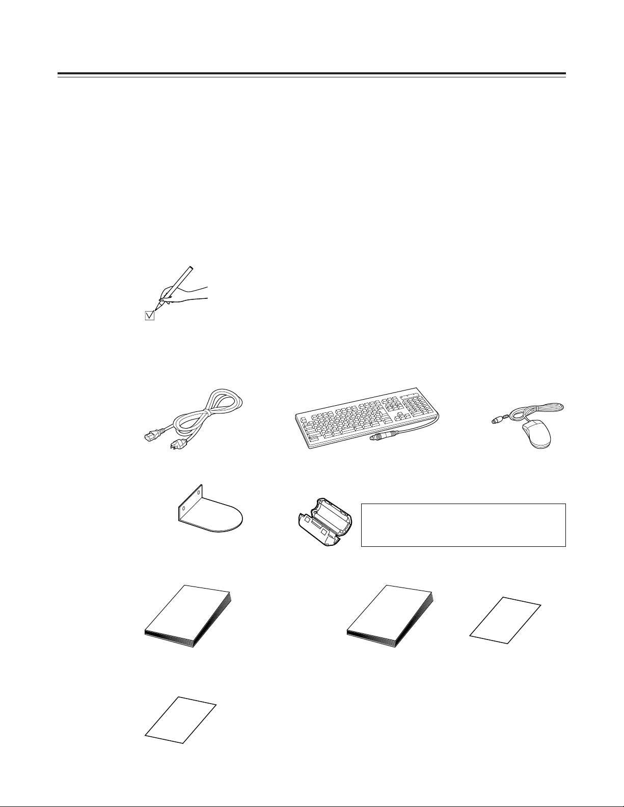
Before proceeding with the connections, check that all the accessories shown
below are present and accounted for.
)
Keyboard
)
Mouse
)
Power cord
)
Operating
instructions
)
Warranty card
)
Stabilizers
(a4)
)
mounting screws
(a8)
)
Installation manual
(which you are now reading)
)
Service support guide
<Check>
Do not subject the supplied mouse, keyboard or cables to strong bumps or shocks. Doing so
could damage them.
)
Ferrite cores
(a4)
When the SCSI hard disk drive for external expansion
purposes is to be connected, attach one ferrite core to
one end of the SCSI I/F cable and the other one to the
other end.
– 5 –
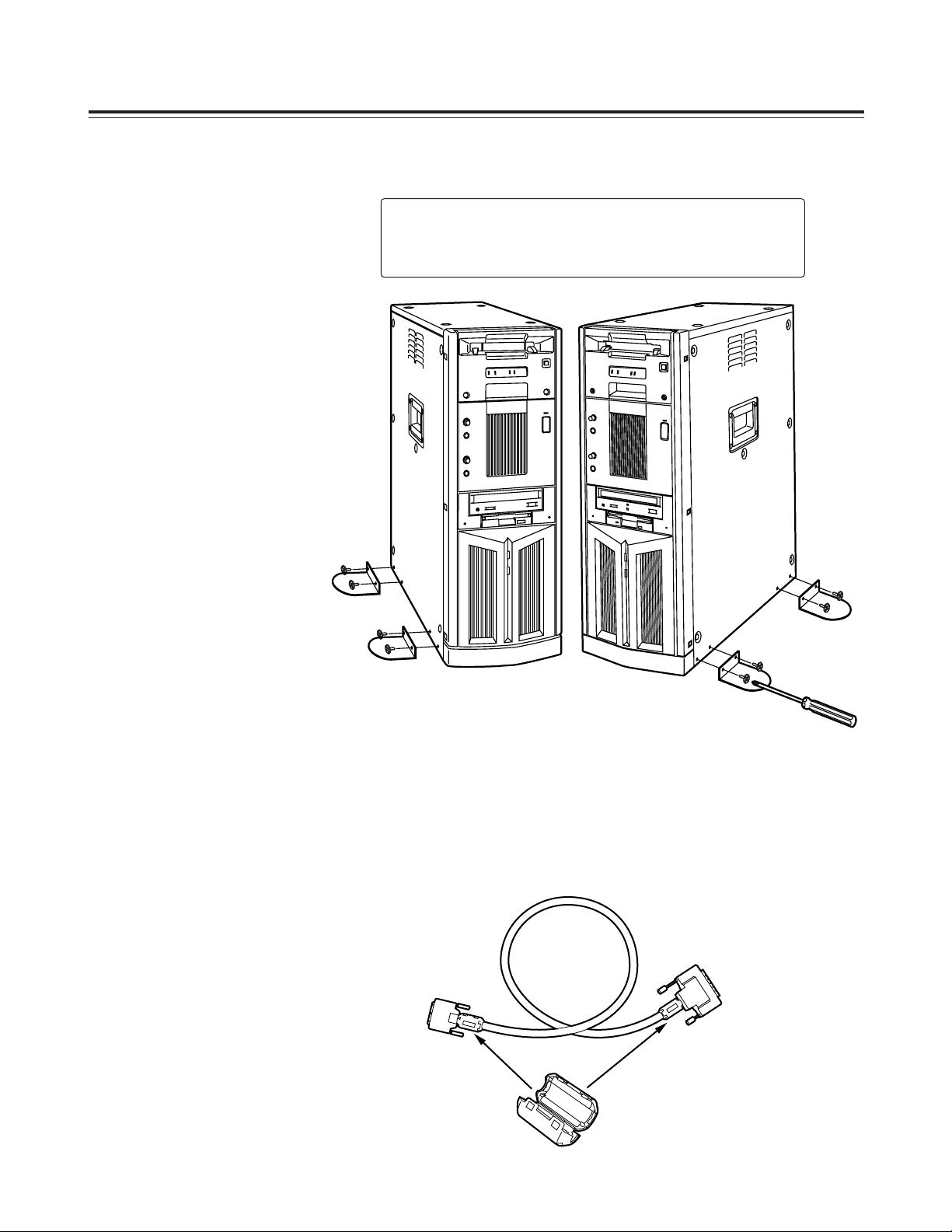
CAUTION:
To reduce the risk of injury due to tipping over,
Mount the stabilizers before installation.
Attaching the stabilizer feet
Attaching the ferrite cores
When the SCSI hard disk drive for external expansion purposes is to be
connected, one of ferrite cores packed with the unit must be attached to one
end of the SCSI I/F cable and the other one must be attached to the other
end.
It is recommended that the cable shown below be used as the SCSII/F cable.
O
Model No. ACK/M-WP made by Adaptec Inc.
– 6 –
1-2. Checking the AC supply voltage and precautions
Use a AC voltmeter or other instrument to check that the supply voltage at
the installation location is inside the following range:
)
120 V ±10 %
1-3. Cable connection precautions (rear panel)
Bear in mind the points listed below when connecting the accessory cables to
the unit’s rear panel. It is recommended that you proceed while referring to
the rear panel connection diagram in the Operating Instructions. (Refer to
page 12 of Operating Instructions.)
)
Connect the keyboard.
)
Connect the mouse.
)
Check the names of the connectors on the rear panel to verify that
the keyboard has not been connected to the mouse connector or the
mouse has not been connected to the keyboard connector.
)
Connect the power cord to the socket on the main unit.
)
Secure the power cord using the clamp.
)
Refrain from connecting the power plug to the power outlet at this
stage.
Note:
Not only may the unit fail to operate properly if it has been started up with
a supply voltage outside the above range but the software programs and
data pre-installed on the system hard disk inside the unit may be
destroyed as well.
Use of an uninterruptible power supply system is recommended if the unit
is to be used in unsatisfactory power supply conditions. For details,
consult with your dealer.
<Check>
<Check>

– 7 –
1-4. Connecting the peripheral devices and layout precautions
Bear in mind the points listed below when connecting the computer monitor,
monitor (Video) for monitoring the pictures and other peripheral devices to
the unit. It is recommended that you proceed while referring to the rear panel
connection diagrams in the Operating Instructions. (Refer to pages 13–16 of
Operating Instructions.)
For details on the handling of peripheral devices, refer to the operating
instructions accompanying each device concerned.
)
Connect the peripheral devices while power to the unit and peripheral
devices is off.
)
Before moving the unit, turn its power off.
Do not move the unit while the power is still on.
)
Install the unit in a flat and stable location.
)
At the installation stage, ensure that the connectors and cables
protruding from the unit’s rear panel do not make contact with any
objects in the vicinity.
)
At the installation stage, do not drop the keyboard or mouse, and
take care not to run their cables underneath the unit or peripheral
devices.
)
Do not place objects on top of the unit.
)
Leave a sufficient clearance around the unit in order to improve the
ventilation inside the unit.
)
Do not place food or drinks in the vicinity of the unit.
Morsels of food or spilled drinks can cause trouble.
)
Check that you have not forgotten to connect the VGA cable between
the unit and the monitor for the computer.
)
Check that you have not forgotten to connect the video cable
between the unit and monitor (Video) for monitoring the pictures.
)
Check that you have not forgotten to connect the unit and any other
peripheral devices.
)
Check that all the devices required have been connected, and insert
the power plugs of the unit and peripheral devices into the power
outlets.
)
When the SCSI hard disk drive for external expansion purposes is to
be connected:
Attach one of the ferrite cores packed with the unit to one end of the
SCSI I/F cable and the attach the other one to the other end.
<Check>

– 8 –
This chapter explains the checks that must be conducted on the basic hardware settings and
basic inspections of the AV disks after the unit’s power switch has been set to the ON
position.
When conducting the checks and inspections described in this chapter, do not turn off the
power or reset the system unnecessarily. Doing so may change or destroy the pre-installed
software programs or data.
For details on turning off the power and resetting the system, refer to the
descriptions given for the items concerned.
2-1. Checking the power startup . . . . . . . . . . . . . . . . . . . . . . . . . . . . . . . . . 8
2-2. Checking the SCSI device settings . . . . . . . . . . . . . . . . . . . . . . . . . . . 10
2-3. AV disk inspections . . . . . . . . . . . . . . . . . . . . . . . . . . . . . . . . . . . . . . . 12
2-1. Checking the power startup
When the unit’s power switch is set to ON, the unit’s basic test is
automatically conducted, and its results can be checked out by beep tones
and displays which appear on the computer monitor.
After the power switches of the computer monitor, monitor (Video) for
monitoring the pictures and other peripheral devices have been set to ON,
set the unit’s power switch to ON and conduct the checks described below at
startup.
If trouble has been detected as a result of conducting the checks, refer to the
“Troubleshooting” section in the Operating Instructions. (Refer to pages
20–27 of the Operating Instructions.)
Since it takes very little time to check the displays on the computer monitor,
you will find it easier to perform the checks if you quickly glance through the
whole of this section and the BIOS screen displays in Appendix A (pages
34–38) and understand what is involved.
For details on how to adjust the monitor and otherwise handle any of the
peripheral devices, refer to the operating instructions accompanying each
device concerned.
Chapter
2
Power startup checks and AV disk inspections
Note:
If a monitor display which should have been checked during startup has
been overlooked, the unit must be rebooted so that it can be checked.
Under no circumstances must the power be turned off or the system
reset while white characters appear on a blue background during
startup.
Wait until the Windows NT flag appears, and then reboot the unit using
the system reset switch on the unit’s front panel.
– 9 –
Checking the LEDs on the unit’s front panel
)
Check that the two disk access lamps light up and flash when the
power is turned on.
Checking the computer monitor displays (BIOS start screen) during
startup
)
Is the memory size value (standard 256 MB) correct?
)
Did the CD-ROM drive name appear (for an instant)?
)
Did the name of the system hard drive appear?
(Refer to the BIOS screen displays in Appendix A.)
)
Did the SCSI card name appear?
(Refer to the BIOS screen displays in Appendix A.)
)
Did all the SCSI disk names appear?
(Refer to the BIOS screen displays in Appendix A.)
)
Did the PCI device list appear?
(Refer to the BIOS screen displays in Appendix A.)
<Check>
<Check>

– 10 –
2-2. Checking the SCSI device settings
In this section the SCSI-BIOS Tool is used to check the SCSI device settings.
You will find it easier to perform the checks if, before starting the actual
procedure, you quickly glance through SCSI-BIOS Tool items B-1–B-3
(pages 39–43) in Appendix B and understand how the settings of the parts
corresponding to the items to be checked in this section are displayed.
In particular, the following parts in B-3 must be understood.
(1) SCSI device configuration check
(2) SCSI ID check
If items with different settings have been detected as a result of conducting
the checks, refer to the explanation given in
¬
When the SCSI device parameters are wrong
¬
which is found in B-3 of Appendix B, and to the “Troubleshooting” section in
the Operating Instructions. (Refer to pages 20–27 of Operating Instructions.)
When the checks in this section have been completed with no errors found,
proceed to the next section [2-3. AV disk inspections] without exiting the
SCSI-BIOS Tool.
1. After the series of checks described in Section 2-1 (Checking the power
startup) have been completed with no errors found, reboot the unit and
check the SCSI device settings.
Note:
If, upon completion of the checks in the previous section, the screen
displays during the startup procedure have reached the white characters
on a blue background status, do not turn off the power or reset the
system until the display status changes.
If either step is to be performed, wait until the Windows flag appears on
the screen, and then reboot the unit using the reset switch.
2. Check the SCSI device settings following the instructions in “(1) SCSI
device configuration check” and “(2) SCSI ID check” in B-3 (pages 40,
41) of Appendix B (SCSI-BIOS Tool).

– 11 –
O
Check the SCSI Channel Interface Definitions.
)
Is the Host Adapter SCSI ID set to “7”?
)
Is the SCSI Parity Checking set to “Enable”?
)
Is the Host Adapter SCSI Termination set to “Automatic”?
SCSI device configuration checks (1)
(Conduct the checks for both channels A and B.)
O
Check the parameters of all the SCSI-ID #0–#15 devices in SCSI
Device Configuration.
(Check that the parameters of all the devices are set as shown below.)
)
Is the Maximum Sync Transfer Rate set to “160”?
)
Is the Initiate Wide Negotiation set to “yes”?
)
Is the Enable Disconnection set to “yes”?
)
Is the Send Start Unit Command set to “yes”?
)
Is the Enable Write Back Cache set to “N/C”?
)
Is the BIOS Multiple LUN Support set to “no”?
)
Is the Include in BIOS Scan set to “yes”?
SCSI device configuration checks (2)
(Conduct the checks for both channels A and B.)
)
Does “Adaptec SCSI Card 39160” appear for SCSI ID #7?
SCSI ID checks
(Conduct the checks for both channels A and B.)
<Check>
<Check>
<Check>
– 12 –
2-3. AV disk inspections
In this section, the AV disks are inspected using the SCSI-BIOS Tool.
These inspections check for defects in the AV disks as recording media. (It
takes about 2 hours to conduct all the inspections in this category.)
1. To return the screen display to the inspection menu selection, press the
[Esc] key several times until the message box shown below is displayed.
2. After selecting [No], press the [Enter] key, follow the displays and return
the device channel (channel A, B) selection screen.
3. Inspect the disks following the instructions on “(3) Inspecting the disk
media” in B-3 (pages 46, 47) of Appendix B (SCSI-BIOS Tool).
Yes
No
Exit Utility ?
Channel A SCSI disk checks
)
Did “Verify Disk” of the SCSI ID #0 disk end with “Disk Verification
Complete”?
)
Did “Verify Disk” of the SCSI ID #1 disk end with “Disk Verification
Complete”?
)
Did “Verify Disk” of the SCSI ID #2 disk end with “Disk Verification
Complete”?
)
Did “Verify Disk” of the SCSI ID #1 disk end with “Disk Verification
Complete”?
)
Did “Verify Disk” of the SCSI ID #2 disk end with “Disk Verification
Complete”?
Channel B SCSI disk checks
4. If all the disks have been inspected with no errors found, refer to B-4
(page 44) in Appendix B, and exit the SCSI-BIOS Tool.
<Check>
<Check>

– 13 –
This chapter describes the checks on the disk-related settings which are conducted on the
startup screen of Windows NT, the operating system used by the unit, and the inspections
conducted on the AV disks to verify whether they can be used by this system.
The inspections described in this chapter are conducted after the Windows NT startup screen
appears normally after the power to all the units and devices has been turned on.
For details on the checks and inspections conducted prior to the appearance of the Windows
NT startup screen, refer to Chapters 1 and 2 of this manual.
3-1. Checking the disk settings . . . . . . . . . . . . . . . . . . . . . . . . . . . . . . . . . 13
3-2. Checking the AudioPool, VideoPool & TitlePool directories . . . . . . . . 15
3-1. Checking the disk settings
The checks in this section are performed after the series of checks described
in the previous chapter have been completed with no errors found.
When the sequence of power startup steps is completed and the waiting-tolog-on dialog box has appeared on the screen, follow the instructions in the
box and complete the logging on procedure for Windows NT.
On the startup window after Windows NT log-on, check the disk settings in
this section using the Disk Administrator which is a Windows NT
management tool.
Before starting the actual procedure, you will find it easier to perform the
checks if you quickly glance through items C-1–C-3 (pages 45, 46) of
Appendix C how to use Disk Administrator provided with Windows NT and
understand how the settings of the parts corresponding to the items to be
checked in this section are displayed.
If items with wrong settings have been detected as a result of conducting the
checks, refer to the explanations with the ¬marks in the sections concerned
in Appendix C and to the “Troubleshooting” section in the Operating
Instructions. (Refer to pages 20–27 of Operating Instructions.)
Chapter
3
Disk-related configuration checks

– 14 –
If the checks in this section have been completed error-free, exit the Disk
Administrator by following the procedure described in item C-6 of Appendix
C.
Disk volume-related status information check using the
Disk Administrator
)
Are 6 disks (excluding the CD-ROM) displayed altogether?
)
Is one CD-ROM drive displayed?
)
Are the names of the drives for disk 0 set to “C:” or “D:”?
)
Is “NTFS” the format of disk 0 for both “C:” and “D:”?
)
Is the name of the drive for disks 1 through 4 set to “O:”?
)
Is the name of the drive for disk 5 set to “L:”?
)
Is “RTLFS” the format of disks 1 through 5?
)
Is the name of the CD-ROM drive set to “E:”?
<Check>
O
Start up the Disk Administrator following the instructions in C-2 (page 45)
of Appendix C.
– 15 –
3-2.
Checking the AudioPool, VideoPool & TitlePool directories
In this section, the Windows NT Explorer is used to check the making of the
AudioPool, VideoPool and TitlePool directories on the Windows NT startup
screen.
1. If there is an application now starting up in Windows NT, exit the
application and start the procedure from the Windows NT startup screen.
2. On the [Start] menu, click [Program] 5[Windows NT Explorer] to start.
3. Click the RTLFS-Volume(L:) drive under My Computer on the left side of
the divided window.
Check the names of the directories which appear in the right
side of the divided window.
)
Does the AudioPool directory (L: \ AudioPool) appear for drive “L:”?
6. When the checks in this section have been completed with no errors
found, click at the top right of the Explorer window, exit the Windows
NT Explorer, and return to the Windows NT startup screen.
<Check>
Check the names of the directories which appear on the right
side of the divided window.
)
Does the TitlePool directory (D:\TitlePool) appear for drive “D:”?
<Check>
)
Does the VideoPool directory (O:\VideoPool) appear for drive “O:”?
)
Does the system directory (O:\system) appear for drive “O:”?
<Check>
4. On the left side of the divided window, click the RTLFS-Volume(O): drive
under “My Computer.”
Check the names of the directories which appear on the right
side of the divided window.
5. On the left side of the divided window, click the System2(D): drive under
“My Computer.”

– 16 –
This chapter explains after the unit has been installed how to conduct comprehensive
operation checks on the hardware of the unit using the limited edition of the editing software
program which is pre-installed in the unit.
Note:
Do not install the editing program until the checks described in this chapter have been
completed. Otherwise, it may no longer be possible to run the limited edition of the
program which was pre-installed.
After the power to the unit has been turned on, wait until the Windows NT startup screen has
appeared without any problem. It is only after this that all the checks described in this
chapter are to be performed. For details on the checks and inspections before this screen
appears, refer to Chapters 1 and 2 of this Manual.
When an external VTR is to be used, connect the external input and output devices to both
the component and composite connectors before starting the checks.
4-1. Checking the uploading operation . . . . . . . . . . . . . . . . . . . . . . . . . . . 16
4-2. Check the editing functions . . . . . . . . . . . . . . . . . . . . . . . . . . . . . . . . . 24
4-3. Checking the downloading operation . . . . . . . . . . . . . . . . . . . . . . . . . 30
4-1. Checking the uploading operation
Proceed with the checks in this section after the series of checks described in
the previous chapters have been completed with no errors found.
In this section, the limited edition of the pre-installed editing software program
is used to check the uploading operation on the startup screen which appears
after Windows NT log-on.
If errors have been detected in the settings as a result of conducting the
checks, refer to the explanations enclosed within the ¬marks in the sections
concerned in Appendix C and to the “Troubleshooting” section in the
Operating Instructions. (Refer to pages 20–27 of Operating Instructions)
1. Double-click the Panasonic NLE System icon (shown below) on the
Windows NT startup screen to start the limited edition of the editing
software program.
(Startup may take ten seconds or so.)
Checking operation using the
pre-installation program
Chapter
4
– 17 –
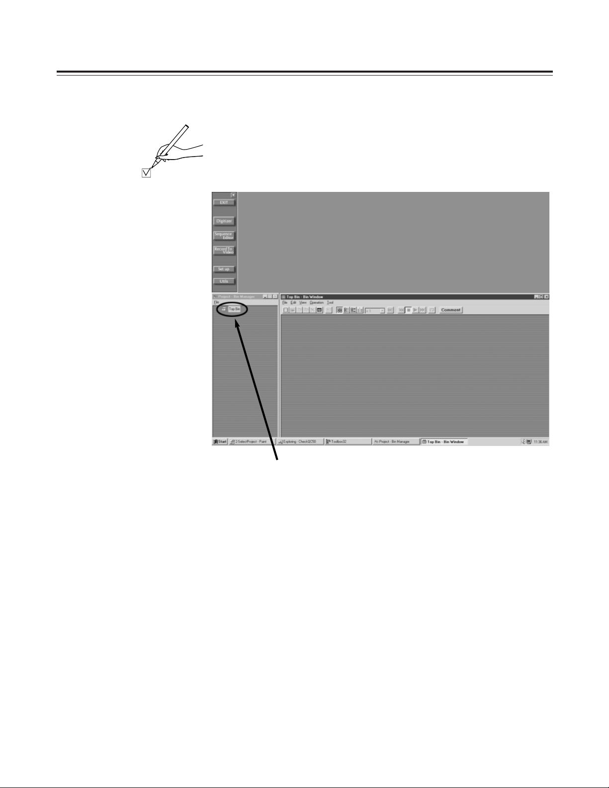
2. The screen shown below now appears.
Double-click Top Bin if the Bin window of Top Bin is not open.
)
Did the screen shown below appear as a result of starting the limited
edition of the editing software program?
<Check>
 Loading...