

Non-Linear Editing System
Operating Instructions
AJ- P
This manual contains information on the hardware only.
For details on video and audio uploading, editing and other
operations, refer to the Reference Manual (AJ-SF97).
– 2 –
indicates safety information.
CAUTION:
Do not install or place this unit in a bookcase,
built-in cabinet or any other confined space in
order to maintain adequate ventilation. Ensure
that curtains and any other materials do not
obstruct the ventilation to prevent risk of
electric shock or fire hazard due to
overheating.
IMPORTANT
“Unauthorized recording of copyrighted television programs, video tapes and other materials may
infringe the right of copyright owners and be contrary to copyright laws.”
FCC Note:
This device complies with Part 15 of the FCC Rules. To
assure continued compliance follow the attached
installation instructions and do not make any
unauthorized modifications.
This equipment has been tested and found to comply
with the limits for a class A digital device, pursuant to
Part 15 of the FCC Rules. These limits are designed to
provide reasonable protection against harmful
interference when the equipment is operated in a
commercial environment. This equipment generates,
uses, and can radiate radio frequency energy and, if not
installed and used in accordance with the instruction
manual, may cause harmful interference to radio
communications. Operation of this equipment in a
residential area is likely to cause harmful interference in
which case the user will be required to correct the
interference at his own expense.
WARNING:
TO REDUCE THE RISK OF FIRE OR SHOCK
HAZARD, DO NOT EXPOSE THIS EQUIPMENT
TO RAIN OR MOISTURE.
CAUTION:
TO REDUCE THE RISK OF FIRE OR SHOCK
HAZARD AND ANNOYING INTERFERENCE,
USE THE RECOMMENDED ACCESSORIES
ONLY.
CAUTION
RISK OF ELECTRIC SHOCK
DO NOT OPEN
CAUTION: TO REDUCE THE RISK OF ELECTRIC SHOCK,
DO NOT REMOVE COVER (OR BACK).
NO USER SERVICEABLE PARTS INSIDE.
REFER TO SERVICING TO QUALIFIED SERVICE PERSONNEL.
The lightning flash with arrowhead symbol,
within an equilateral triangle, is intended to
alert the user to the presence of uninsulated
“dangerous voltage” within the product’s
enclosure that may be of sufficient magnitude
to constitute a risk of electric shock to
persons.
The exclamation point within an equilateral
triangle is intended to alert the user to the
presence of important operating and
maintenance (service) instructions in the
literature accompanying the appliance.
CAUTION:
TO REDUCE THE RISK OF FIRE OR SHOCK
HAZARD, REFER CHANGE OF SWITCH
SETTING INSIDE THE UNIT TO QUALIFIED
SERVICE PERSONNEL.
CAUTION:
A CD-ROM DRIVE (CLASS 1 LASER PRODUCT)
IS INSTALLED IN THE PRODUCT.
USE OF CONTROLS OR ADJUSTMENTS OR
PERFORMANCE OF PROCEDURES OTHER
THAN THOSE SPECIFIED HEREIN MAY
RESULT IN HAZARDOUS RADIATION
EXPOSURE.
DO NOT MAKE ANY MODIFICATIONS. DO NOT
REPAIR BY YOURSELF. REFER SERVICING
TO QUALIFIED PERSONNEL.
CAUTION:
TO REDUCE THE RISK OF FIRE OR SHOCK
HAZARD, REFER INSTALLATION OF HARDDISK DRIVE TO QUALIFIED SERVICE
PERSONNEL.
HARD-DISK DRIVE MUST BE APPROVED BY
UL AND/OR CSA.
CAUTION:
TO REDUCE THE RISK OF FIRE OR SHOCK
HAZARD, REFER MOUNTING OF THE
OPTIONAL INTERFACE BOARD TO
QUALIFIED SERVICE PERSONNEL.

– 3 –
Contents
Features . . . . . . . . . . . . . . . . . . . . . . . . . . . . . . . . . . . . . . . . . . . . . . 4
Warning. . . . . . . . . . . . . . . . . . . . . . . . . . . . . . . . . . . . . . . . . . . . . . . 4
System Configuration . . . . . . . . . . . . . . . . . . . . . . . . . . . . . . . . . . . 5
Parts and Their Functions. . . . . . . . . . . . . . . . . . . . . . . . . . . . . . . . 6
Front Panel . . . . . . . . . . . . . . . . . . . . . . . . . . . . . . . . . . . . . . . . . . . 6
LED Display Panel . . . . . . . . . . . . . . . . . . . . . . . . . . . . . . . . . . . . . 7
Rear Panel . . . . . . . . . . . . . . . . . . . . . . . . . . . . . . . . . . . . . . . . . . . 8
Connections . . . . . . . . . . . . . . . . . . . . . . . . . . . . . . . . . . . . . . . . . . 12
Basic Connections . . . . . . . . . . . . . . . . . . . . . . . . . . . . . . . . . . . . 12
Monitor Connections. . . . . . . . . . . . . . . . . . . . . . . . . . . . . . . . . . . 13
VTR Connections . . . . . . . . . . . . . . . . . . . . . . . . . . . . . . . . . . . . . 14
Audio Equipment Connections . . . . . . . . . . . . . . . . . . . . . . . . . . . 15
Editing Control Pad Connections . . . . . . . . . . . . . . . . . . . . . . . . . 16
System Startup and Exit . . . . . . . . . . . . . . . . . . . . . . . . . . . . . . . . 17
System Startup . . . . . . . . . . . . . . . . . . . . . . . . . . . . . . . . . . . . . . . 17
System Exit. . . . . . . . . . . . . . . . . . . . . . . . . . . . . . . . . . . . . . . . . . 18
Troubleshooting. . . . . . . . . . . . . . . . . . . . . . . . . . . . . . . . . . . . . . . 20
Connector Signals . . . . . . . . . . . . . . . . . . . . . . . . . . . . . . . . . . . . . 28
Error Items . . . . . . . . . . . . . . . . . . . . . . . . . . . . . . . . . . . . . . . . . . . 30
When the WARNING lamp is lighted . . . . . . . . . . . . . . . . . . . . . . 30
When the AUTO OFF lamp is lighted . . . . . . . . . . . . . . . . . . . . . . 30
Maintenance and Care. . . . . . . . . . . . . . . . . . . . . . . . . . . . . . . . . . 33
Video Head Cleaning . . . . . . . . . . . . . . . . . . . . . . . . . . . . . . . . . . 33
Condensation . . . . . . . . . . . . . . . . . . . . . . . . . . . . . . . . . . . . . . . . . 33
Specifications. . . . . . . . . . . . . . . . . . . . . . . . . . . . . . . . . . . . . . . . . 34
O
Windows and Windows NT are registered trademarks of Microsoft Corporation.
O
Pentium is a registered trademark of Intel Corporation.
All other names of companies and products are the trademarks or registered trademarks of the companies
concerned.

– 4 –
Features
All-in-one tower design
This system contains a internal VTR for uploading and downloading data.
This feature translates into savings in terms of both the cost and space required for an externally connected
VTR, and it enables DVCPRO tapes to be loaded just like floppy disks or magneto-optical disks. The unit also
contains a hard disk for audio-video recording, and its size is the same as a tower-type personal computer. It
can be placed by the side of a desk for highly efficient editing operations.
Transfer and saving at twice/4 times normal speed
Data can be uploaded and downloaded between the internal VTR and hard drive at a speed of 2a(DVCPRO
50) or 4a(DVCPRO): this makes it possible to accomplish the preparatory work which has been viewed as a
kind of bottleneck in non-linear editing much more quickly.
Same high picture quality recording as with DVCPRO 50/DVCPRO
The same digital component compression recording system as for DVCPRO 50/DVCPRO is used to record data
onto the hard disk. The resulting picture quality is higher than that achieved by JPEG which has been adopted
by many non-linear editors (comparison made at the same transfer rate).
Furthermore, 140 minutes (with DVCPRO 50) or 280 minutes (with DVCPRO) of video and/or audio data can be
recorded on the internal hard drive (standard specification: 72GB).
Transfer of data while still compressed
Data still in a compressed format can be uploaded and downloaded between the internal VTR and hard drive.
Due to the absence of the A/D (D/A) conversion and compression/expansion processes, the picture quality of the
data is not subject to any deterioration whatsoever during the transfer process.
Editing of data while still compressed
In the case of cut editing, the unit leaves the recorded data completely unchanged. With the data still in its
compressed form, changes are made only to the read sequence and positions. During recording, the
compressed data does not need to be expanded at all, and it can be edited up to the form taken by the
completed package. This means that high picture quality is maintained even after editing.
(When the special effect and superimpose functions are used, the data is expanded into full bit digital video data,
and compressed back again after processing.)
Real-time preview of special effects
The unit contains a switcher so that wipe, dissolve and other special effects can be previewed on a real-time
basis during A/B roll editing. Trial-and-error operations can be repeated any number of times while checking
how the results turn out.
External VTR control (RS-422A)
The unit’s RS-422A (9 Pin) remote connector enables a wide range of analog or digital VTRs to be controlled.
This feature can also be used to introduce material or transmit perfect package programs using external VTRs.
All the proven features of the AJ-DE77’s operation system adopted
The user interfaces of the AJ-DE77 have served as a solid foundation on which to introduce improvements into
the system’s operating ease.
Streamlined operations using mouse
All the operator has to do in order to add, replace or delete cuts is rearrange the clips by operating the mouse.
Cut editing can be achieved with excellent response.
Warning
1. This unit must not be used on board a vehicle.
Doing so may damage the hard disk drive and destroy the data.
2. The user must not install any software programs which have not been designated for
use with this system.
The system may not operate properly if such programs are installed. For further details, consult your dealer.
– 5 –
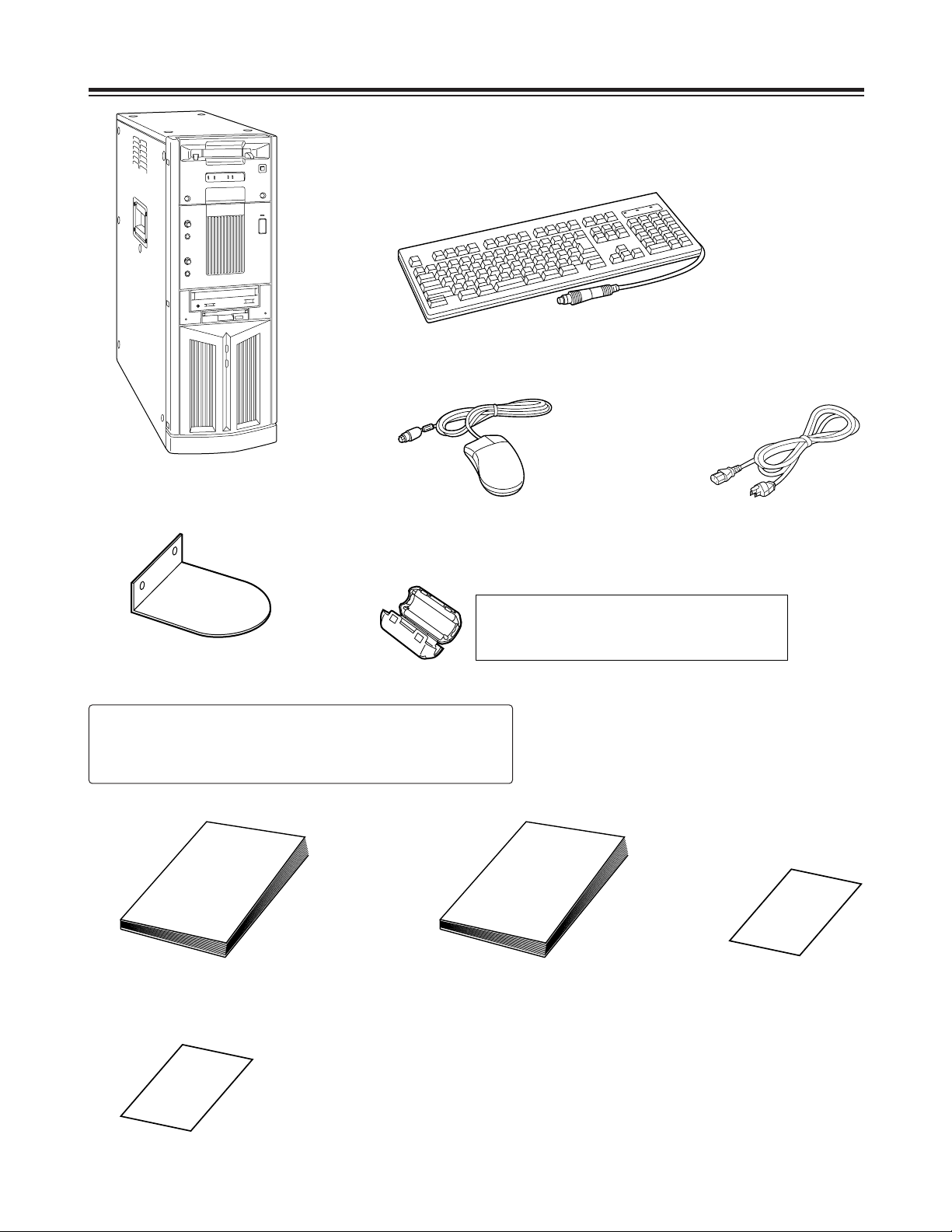
System Configuration
Main unit
Keyboard
Mouse Power cord
Operating instructions
(which you are now reading)
Warranty card
Stabilizers
(a4)
mounting screws
(a8)
Installation manual
CAUTION:
To reduce the risk of injury due to tipping over,
mount the stabilizers before installation.
Service support guide
Do not subject the supplied mouse, keyboard or cables to strong bumps or
shocks. Doing so could damage them.
Ferrite cores
(a4)
When the SCSI hard disk drive for external expansion
purposes is to be connected, attach one ferrite core to
one end of the SCSI I/F cable and the other one to the
other end.
– 6 –
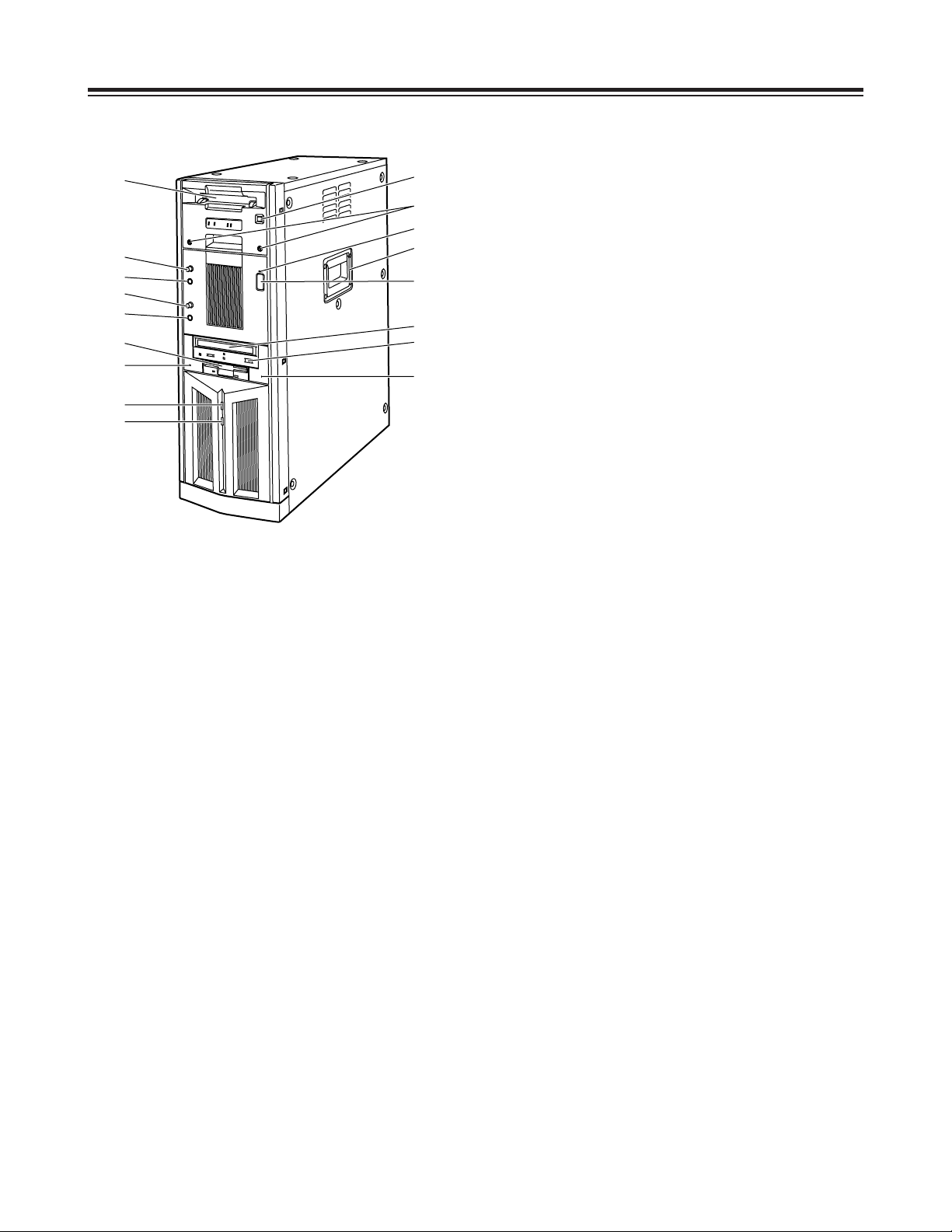
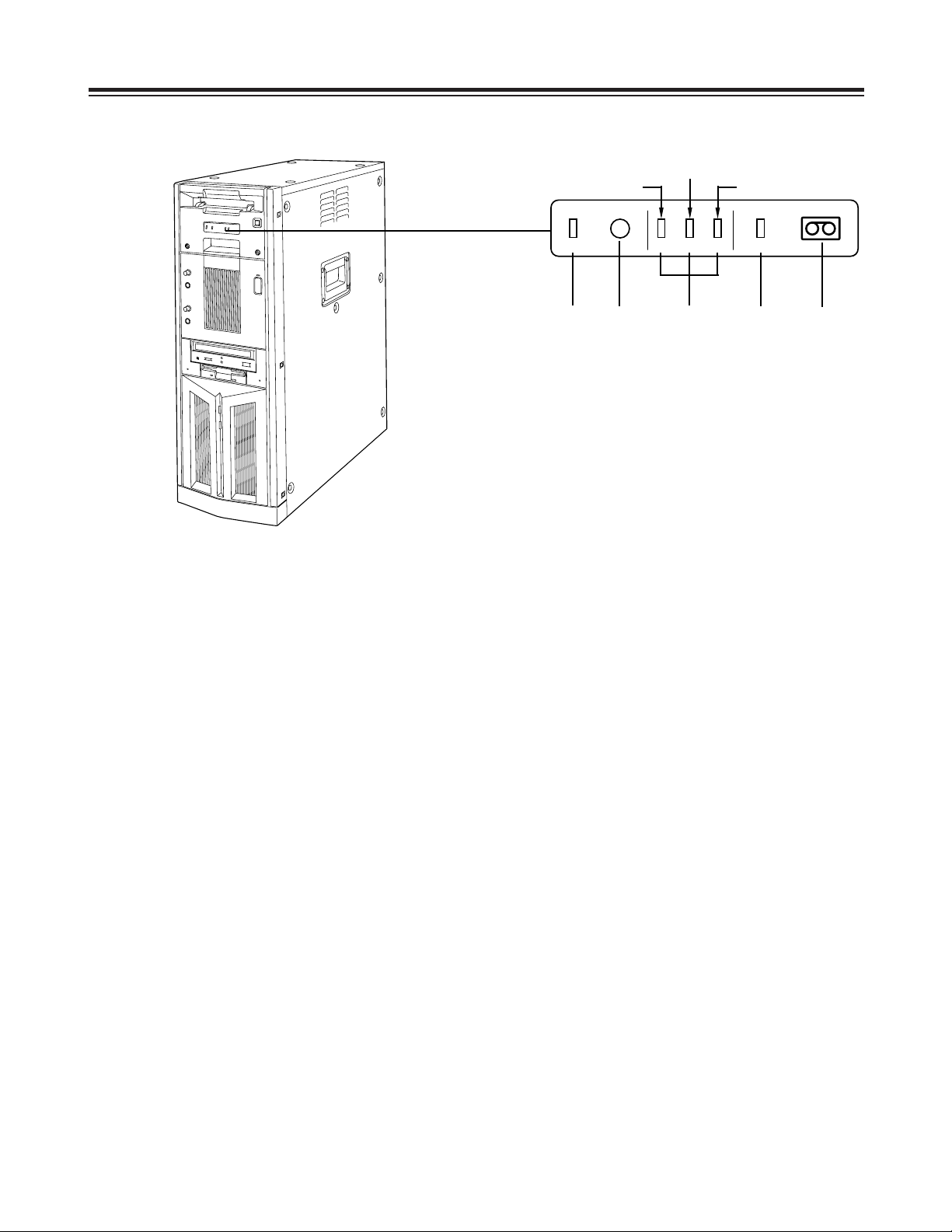
Parts and Their Functions
Front Panel
1
Main unit power switch
Set this switch to the OFF position after quitting the
system. If the power is turned off while the hard
disk drive is operating, data may be lost or the drive
may be damaged.
Do NOT turn off the power while white characters
on a blue background appear on the monitor
display (for the personal computer) during startup.
2
Main unit power LED
3
HDD sub switch
Press this switch if PC unit’s power does not come
on even when the main unit power switch is set to
ON.
Do not press this switch without good reason since
the power of the PC unit will be turned off if it
pressed while the power is supplied.
4
HDD reset switch
Press this switch when the PC unit is not operating
properly. The start screen will now be restored,
and checks on the operation can be carried out.
Do NOT press this switch while white characters on
a blue background appear on the monitor display
(for the personal computer) during startup.
5
Phones jack
The sound can be monitored when stereo
headphones are connected to this jack.
6
Phones volume control
This is used to adjust the headphones volume and
the monitor output volume.
7
Mic jack
The microphone is connected here for voice-over
editing operations.
8
Mic volume control
This is used to adjust the level at which the
microphone sound is input.
9
Cassette slot
M cassettes or L cassettes are loaded through this
slot. Consumer-use cassettes cannot be used for
recording or playback.
:
Cassette tape EJECT button.
When this button is pressed, the tape is unloaded,
and the cassette is automatically ejected several
seconds later.
;
CD-ROM drive
<
Tray OPEN/CLOSE button
=
Floppy disk drive
>
Carrying handle
?
HDD access display lamp (system)
@
HDD access display lamp (AV data)
A
Screws for securing mechanism
Loosen these screws when cleaning the head
mechanism transport system of the VTR unit or
when conducting other kinds of servicing or
maintenance. It will then be possible to pull out the
VTR unit’s mechanism.
After the maintenance work has been completed or
when the unit is to be moved, the mechanism must
be put back inside the unit and the screws
tightened up securely.
9
6
5
8
=
4
?
@
7
3
;
2
:
A
>
1
<
– 7 –
Parts and Their Functions
LED Display Panel
1
AUTO OFF lamp
This lights when trouble has occurred in the unit’s
operation.
2
Warning lamp
This lights when a warning item has occurred.
3
Channel condition lamps
One of these lamps lights in accordance with the
error rate status.
(Green 5yellow 5amber)
Green: This lights when the video and audio play
signal error rates are at acceptable levels.
Yellow: This lights when either the video or audio
play signal error rate has deteriorated.
The playback picture remains normal even
while this lamp is lighted.
Amber: This lights when either the video or audio
play signal error rate is subject to
correction or interpolation.
4
VTR lamp
This lights while the tape is traveling.
5
Cassette loaded lamp
This lights when a cassette has been loaded in the
unit.
LED display panel
(Yellow)
(Amber)
(Green)
21345
AUTO OFF
W
CH CONDITION
VTR

– 8 –
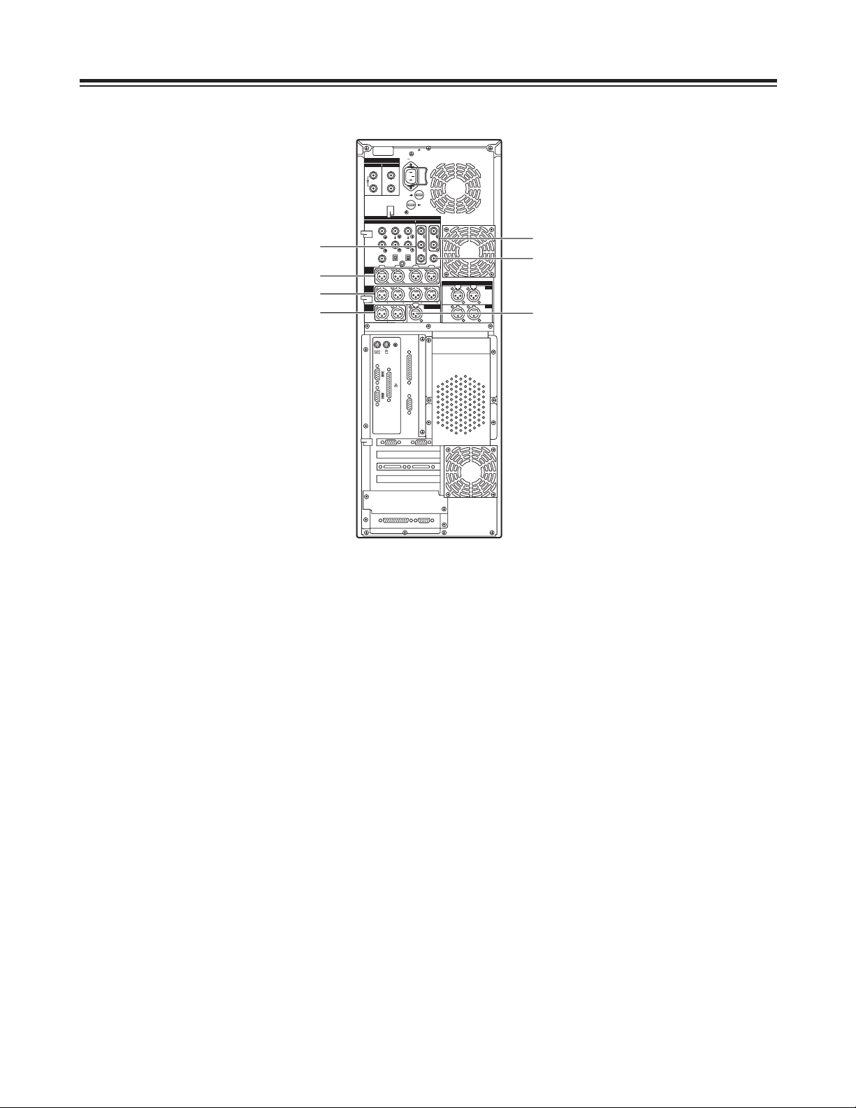
Parts and Their Functions
Rear Panel
1
AC power socket [~AC IN]
The power cord (provided) is connected to this
socket.
2
Fuse holder [FUSE 1/2, 125 V, 5 A]
This holder contains a 5 A fuse.
FUSE 1: for VTR unit
FUSE 2: for PC unit
3
Ventilating fan
This fan prevents the internal temperature from
rising. Do not block the fan openings by placing the
unit right up against a wall or other object.
4
Analog component video signal input
connectors [ANALOG, VIDEO INPUT, Y/P
B/PR
]
The analog component video signals are supplied
to these connectors. Connect a VTR or other video
unit with a component signal output capability here.
5
Analog composite video signal input connectors
[ANALOG, VIDEO INPUT, VIDEO IN]
The analog composite video signals are supplied to
these connectors which are joined by a loopthrough configuration. Connect a VTR or other
video unit with a composite signal output capability
here.
6
Analog reference video signal input connectors
[ANALOG, VIDEO INPUT, REF VIDEO IN]
The analog reference video signals are supplied to
these connectors which are joined by a loopthrough configuration.
In order to ensure that the video and audio signals
played back are stable, supply stable black burst
signals to these connectors from an external sync
signal generator.
7
75-ohm termination switch
Set this to ON for termination.
8
Serial digital video signal input connectors
[SDI/SDTI IN] (option)
(For details on supporting this option, consult your
dealer.)
9
Serial digital video signal output connectors
[SDI/SDTI OUT] (option)
(For details on supporting this option, consult your
dealer.)
AC IN
FUSE F1
125V
5A
FUSE F2
125V
5A
SIGNAL GND
IN OUT
1
2
SDI/SDIT
SDI/SDIT
ACTIVE THROUGH
SDI/SDIT
(OPTION)
SDI
Y
ANALOG
VIDEO INPUT VIDEO OUTPUT
Y1
2
AUDIO
IN
AUDIO
OUT
AUDIO
MON
TC IN
IN
OUT
DIGITAL AUDIO
MON
OUT
VIDEO
IN
REF VODEO
IN
P
B
P
R
P
B
P
R
ON
OFF
75≠
ON
OFF
75≠
CH1 CH2 CH3
PUSH
CH4
CH1 CH2
LR
RS-232C
SERIAL 1
SERIAL 2
RS-422A
CH1-2 CH3-4
CH3 CH4
PUSH PUSH PUSH PUSH
CH1-2 CH3-4
PUSH PUSH
8
4
9
2
1
3
3
3
3
7
5
6
– 9 –
Parts and Their Functions
Rear Panel
:
Analog component video signal output
connectors [ANALOG, VIDEO OUTPUT, Y/P
B/PR
]
The analog component video signals are output
from these connectors. Connect a VTR or other
video unit with a component signal input capability
here.
;
Analog composite video signal output
connectors [ANALOG, VIDEO OUTPUT, 1/2]
The analog composite video signals are output from
these connectors.
Connect a VTR or other video unit with a composite
signal input capability here.
<
Analog video monitor signal output connector
[ANALOG, VIDEO OUTPUT, MON OUT]
The analog composite video signals with
superimposed data are output from this connector.
Connect an monitor (Video) for monitoring the
pictures here.
=
Analog audio signal input connectors
[ANALOG, AUDIO INPUT, CH1/CH2/CH3/CH4]
The analog audio signals are supplied to these
connectors. Connect a CD player, VTR or other
audio unit capable of outputting analog audio
signals to these connectors.
>
Analog audio signal output connectors
[ANALOG, AUDIO OUTPUT, CH1/CH2/CH3/CH4]
The analog audio signals are output from these
connectors. Connect an audio amplifier, VTR other
audio unit capable of handling analog audio signals
to these connectors.
?
Analog audio monitor signal output connectors
[ANALOG, AUDIO MON, L/R]
The audio playback signals are output from these
connectors. Connect monitor speakers, etc. to
them.
@
Time code signal input connector [TC IN]
This connector is used when the time code signals
from an external source are to be supplied.
AC IN
FUSE F1
125V
5A
FUSE F2
125V
5A
SIGNAL GND
IN OUT
1
2
SDI/SDIT
SDI/SDIT
ACTIVE THROUGH
SDI/SDIT
(OPTION)
SDI
Y
ANALOG
VIDEO INPUT VIDEO OUTPUT
Y1
2
AUDIO
IN
AUDIO
OUT
AUDIO
MON
TC IN
IN
OUT
DIGITAL AUDIO
MON
OUT
VIDEO
IN
REF VODEO
IN
P
B
P
R
P
B
P
R
ON
OFF
75≠
ON
OFF
75≠
CH1 CH2 CH3
PUSH
CH4
CH1 CH2
LR
RS-232C
SERIAL 1
SERIAL 2
RS-422A
CH1-2 CH3-4
CH3 CH4
PUSH PUSH PUSH PUSH
CH1-2 CH3-4
PUSH PUSH
:
=
;
<
@
>
?
– 10 –
Parts and Their Functions
Rear Panel
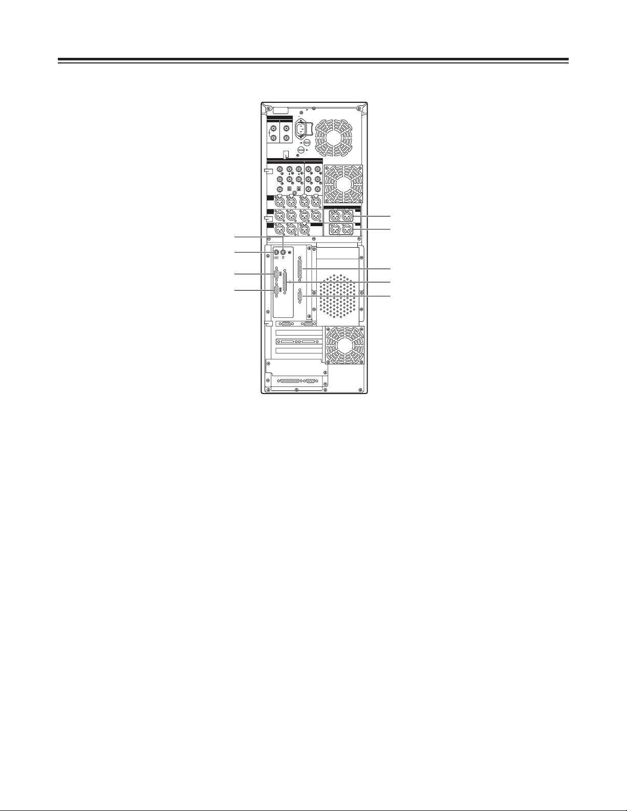
A
Digital audio signal input connector
[DIGITAL AUDIO IN, CH1-2/CH3-4]
The digital audio signals in the AES/EBU format are
supplied to these connectors.
B
Digital audio signal output connectors
[DIGITAL AUDIO OUT, CH1-2/CH3-4]
Connect a VTR equipped with AES/EBU input
connectors here.
C
Serial 1 connector [SERIAL 1]
Spare connector
D
Mouse connector [MOUSE]
Connect the mouse (provided) here.
E
Keyboard connector [KEYBOARD]
Connect the keyboard (provided) here.
F
Parallel connector [PARALLEL]
Connect a device with a parallel interface here.
G
Serial 2 connector [SERIAL 2]
Spare connector
H
RS-232C connector [RS-232C]
Connect the editing pad here.
(Options supported: For details, please consult with
your dealer.)
I
RS-422A connector [RS-422A]
Connect an external VTR (External VTR1) which
can be controlled using an RS-422A interface to
control its recording and playback functions.
AC IN
FUSE F1
125V
5A
FUSE F2
125V
5A
SIGNAL GND
IN OUT
1
2
SDI/SDIT
SDI/SDIT
ACTIVE THROUGH
SDI/SDIT
(OPTION)
SDI
Y
ANALOG
VIDEO INPUT VIDEO OUTPUT
Y1
2
AUDIO
IN
AUDIO
OUT
AUDIO
MON
TC IN
IN
OUT
DIGITAL AUDIO
MON
OUT
VIDEO
IN
REF VODEO
IN
P
B
P
R
P
B
P
R
ON
OFF
75≠
ON
OFF
75≠
CH1 CH2 CH3
PUSH
CH4
CH1 CH2
LR
RS-232C
SERIAL 1
SERIAL 2
RS-422A
CH1-2 CH3-4
CH3 CH4
PUSH PUSH PUSH PUSH
CH1-2 CH3-4
PUSH PUSH
D
E
I
H
B
C
G
F
A
– 11 –
Parts and Their Functions
Rear Panel
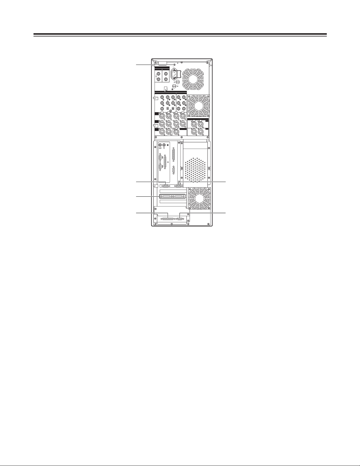
J
SCSI connector
Connect a SCSI hard disk drive for external
expansion purposes.
(Future plans call for this connector to be used to
support some options. For details, please consult
with your dealer.)
K
RS-232C connector
Spare connector (for maintenance purposes)
L
SVGA I/F connector
This is connected to the SVGA monitor.
M
SVGA I/F connector
Spare connector
N
RS-422A connector [RS-422A]
Connect an external VTR (External VTR2) which
can be controlled using an RS-422A interface to
control its recording and playback functions.
O
SIGNAL GND terminal
This is connected to the signal ground terminal on
the unit connected in order to reduce the noise.
It is not a safety ground.
AC IN
FUSE F1
125V
5A
FUSE F2
125V
5A
SIGNAL GND
IN OUT
1
2
SDI/SDIT
SDI/SDIT
ACTIVE THROUGH
SDI/SDIT
(OPTION)
SDI
Y
ANALOG
VIDEO INPUT VIDEO OUTPUT
Y1
2
AUDIO
IN
AUDIO
OUT
AUDIO
MON
TC IN
IN
OUT
DIGITAL AUDIO
MON
OUT
VIDEO
IN
REF VODEO
IN
P
B
P
R
P
B
P
R
ON
OFF
75≠
ON
OFF
75≠
CH1 CH2 CH3
PUSH
CH4
CH1 CH2
LR
RS-232C
SERIAL 1
SERIAL 2
RS-422A
CH1-2 CH3-4
CH3 CH4
PUSH PUSH PUSH PUSH
CH1-2 CH3-4
PUSH PUSH
M
L
J
K
N
O
– 12 –
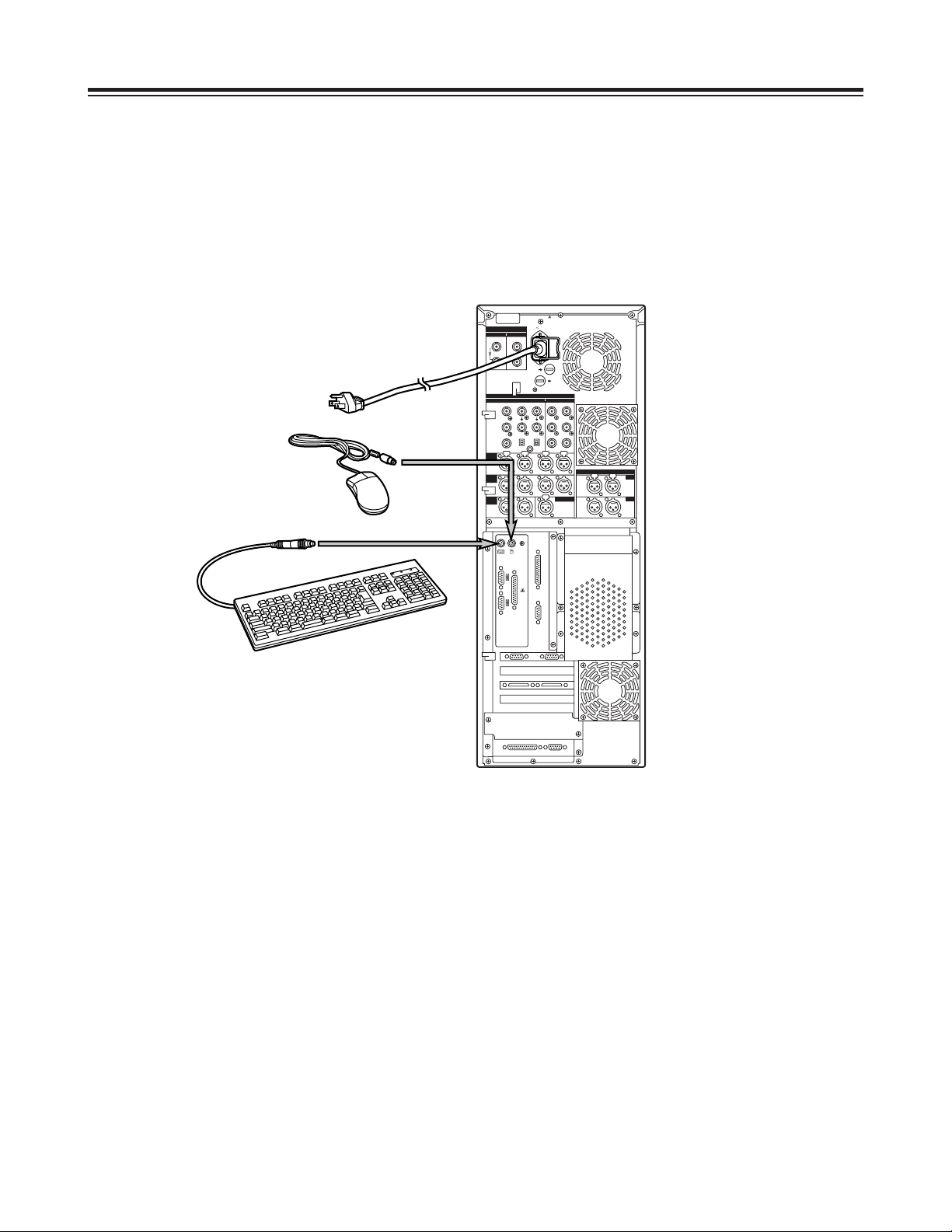
Connections
Basic Connections
(Connecting the power cord, keyboard, mouse and system cables)
1. Connect the keyboard and mouse to their respective connectors.
2. Connect the power cord.
AC IN
FUSE F1
125V
5A
FUSE F2
125V
5A
SIGNAL GND
IN OUT
1
2
SDI/SDIT
SDI/SDIT
ACTIVE THROUGH
SDI/SDIT
(OPTION)
SDI
Y
ANALOG
VIDEO INPUT VIDEO OUTPUT
Y1
2
AUDIO
IN
AUDIO
OUT
AUDIO
MON
TC IN
IN
OUT
DIGITAL AUDIO
MON
OUT
VIDEO
IN
REF VODEO
IN
P
B
P
R
P
B
P
R
ON
OFF
75≠
ON
OFF
75≠
CH1 CH2 CH3
PUSH
CH4
CH1 CH2
LR
RS-232C
SERIAL 1
SERIAL 2
RS-422A
CH1-2 CH3-4
CH3 CH4
PUSH PUSH PUSH PUSH
CH1-2 CH3-4
PUSH PUSH
Main unit
Power cord
Keyboard
Mouse
 Loading...