

Page 1
Non-Linear Editing System
Operating Instructions
AJ- P
This manual contains information on the hardware only.
For details on video and audio uploading, editing and other
operations, refer to the Reference Manual (AJ-SF97).
Page 2
– 2 –
indicates safety information.
CAUTION:
Do not install or place this unit in a bookcase,
built-in cabinet or any other confined space in
order to maintain adequate ventilation. Ensure
that curtains and any other materials do not
obstruct the ventilation to prevent risk of
electric shock or fire hazard due to
overheating.
IMPORTANT
“Unauthorized recording of copyrighted television programs, video tapes and other materials may
infringe the right of copyright owners and be contrary to copyright laws.”
FCC Note:
This device complies with Part 15 of the FCC Rules. To
assure continued compliance follow the attached
installation instructions and do not make any
unauthorized modifications.
This equipment has been tested and found to comply
with the limits for a class A digital device, pursuant to
Part 15 of the FCC Rules. These limits are designed to
provide reasonable protection against harmful
interference when the equipment is operated in a
commercial environment. This equipment generates,
uses, and can radiate radio frequency energy and, if not
installed and used in accordance with the instruction
manual, may cause harmful interference to radio
communications. Operation of this equipment in a
residential area is likely to cause harmful interference in
which case the user will be required to correct the
interference at his own expense.
WARNING:
TO REDUCE THE RISK OF FIRE OR SHOCK
HAZARD, DO NOT EXPOSE THIS EQUIPMENT
TO RAIN OR MOISTURE.
CAUTION:
TO REDUCE THE RISK OF FIRE OR SHOCK
HAZARD AND ANNOYING INTERFERENCE,
USE THE RECOMMENDED ACCESSORIES
ONLY.
CAUTION
RISK OF ELECTRIC SHOCK
DO NOT OPEN
CAUTION: TO REDUCE THE RISK OF ELECTRIC SHOCK,
DO NOT REMOVE COVER (OR BACK).
NO USER SERVICEABLE PARTS INSIDE.
REFER TO SERVICING TO QUALIFIED SERVICE PERSONNEL.
The lightning flash with arrowhead symbol,
within an equilateral triangle, is intended to
alert the user to the presence of uninsulated
“dangerous voltage” within the product’s
enclosure that may be of sufficient magnitude
to constitute a risk of electric shock to
persons.
The exclamation point within an equilateral
triangle is intended to alert the user to the
presence of important operating and
maintenance (service) instructions in the
literature accompanying the appliance.
CAUTION:
TO REDUCE THE RISK OF FIRE OR SHOCK
HAZARD, REFER CHANGE OF SWITCH
SETTING INSIDE THE UNIT TO QUALIFIED
SERVICE PERSONNEL.
CAUTION:
A CD-ROM DRIVE (CLASS 1 LASER PRODUCT)
IS INSTALLED IN THE PRODUCT.
USE OF CONTROLS OR ADJUSTMENTS OR
PERFORMANCE OF PROCEDURES OTHER
THAN THOSE SPECIFIED HEREIN MAY
RESULT IN HAZARDOUS RADIATION
EXPOSURE.
DO NOT MAKE ANY MODIFICATIONS. DO NOT
REPAIR BY YOURSELF. REFER SERVICING
TO QUALIFIED PERSONNEL.
CAUTION:
TO REDUCE THE RISK OF FIRE OR SHOCK
HAZARD, REFER INSTALLATION OF HARDDISK DRIVE TO QUALIFIED SERVICE
PERSONNEL.
HARD-DISK DRIVE MUST BE APPROVED BY
UL AND/OR CSA.
CAUTION:
TO REDUCE THE RISK OF FIRE OR SHOCK
HAZARD, REFER MOUNTING OF THE
OPTIONAL INTERFACE BOARD TO
QUALIFIED SERVICE PERSONNEL.
Page 3

– 3 –
Contents
Features . . . . . . . . . . . . . . . . . . . . . . . . . . . . . . . . . . . . . . . . . . . . . . 4
Warning. . . . . . . . . . . . . . . . . . . . . . . . . . . . . . . . . . . . . . . . . . . . . . . 4
System Configuration . . . . . . . . . . . . . . . . . . . . . . . . . . . . . . . . . . . 5
Parts and Their Functions. . . . . . . . . . . . . . . . . . . . . . . . . . . . . . . . 6
Front Panel . . . . . . . . . . . . . . . . . . . . . . . . . . . . . . . . . . . . . . . . . . . 6
LED Display Panel . . . . . . . . . . . . . . . . . . . . . . . . . . . . . . . . . . . . . 7
Rear Panel . . . . . . . . . . . . . . . . . . . . . . . . . . . . . . . . . . . . . . . . . . . 8
Connections . . . . . . . . . . . . . . . . . . . . . . . . . . . . . . . . . . . . . . . . . . 12
Basic Connections . . . . . . . . . . . . . . . . . . . . . . . . . . . . . . . . . . . . 12
Monitor Connections. . . . . . . . . . . . . . . . . . . . . . . . . . . . . . . . . . . 13
VTR Connections . . . . . . . . . . . . . . . . . . . . . . . . . . . . . . . . . . . . . 14
Audio Equipment Connections . . . . . . . . . . . . . . . . . . . . . . . . . . . 15
Editing Control Pad Connections . . . . . . . . . . . . . . . . . . . . . . . . . 16
System Startup and Exit . . . . . . . . . . . . . . . . . . . . . . . . . . . . . . . . 17
System Startup . . . . . . . . . . . . . . . . . . . . . . . . . . . . . . . . . . . . . . . 17
System Exit. . . . . . . . . . . . . . . . . . . . . . . . . . . . . . . . . . . . . . . . . . 18
Troubleshooting. . . . . . . . . . . . . . . . . . . . . . . . . . . . . . . . . . . . . . . 20
Connector Signals . . . . . . . . . . . . . . . . . . . . . . . . . . . . . . . . . . . . . 28
Error Items . . . . . . . . . . . . . . . . . . . . . . . . . . . . . . . . . . . . . . . . . . . 30
When the WARNING lamp is lighted . . . . . . . . . . . . . . . . . . . . . . 30
When the AUTO OFF lamp is lighted . . . . . . . . . . . . . . . . . . . . . . 30
Maintenance and Care. . . . . . . . . . . . . . . . . . . . . . . . . . . . . . . . . . 33
Video Head Cleaning . . . . . . . . . . . . . . . . . . . . . . . . . . . . . . . . . . 33
Condensation . . . . . . . . . . . . . . . . . . . . . . . . . . . . . . . . . . . . . . . . . 33
Specifications. . . . . . . . . . . . . . . . . . . . . . . . . . . . . . . . . . . . . . . . . 34
O
Windows and Windows NT are registered trademarks of Microsoft Corporation.
O
Pentium is a registered trademark of Intel Corporation.
All other names of companies and products are the trademarks or registered trademarks of the companies
concerned.
Page 4

– 4 –
Features
All-in-one tower design
This system contains a internal VTR for uploading and downloading data.
This feature translates into savings in terms of both the cost and space required for an externally connected
VTR, and it enables DVCPRO tapes to be loaded just like floppy disks or magneto-optical disks. The unit also
contains a hard disk for audio-video recording, and its size is the same as a tower-type personal computer. It
can be placed by the side of a desk for highly efficient editing operations.
Transfer and saving at twice/4 times normal speed
Data can be uploaded and downloaded between the internal VTR and hard drive at a speed of 2a(DVCPRO
50) or 4a(DVCPRO): this makes it possible to accomplish the preparatory work which has been viewed as a
kind of bottleneck in non-linear editing much more quickly.
Same high picture quality recording as with DVCPRO 50/DVCPRO
The same digital component compression recording system as for DVCPRO 50/DVCPRO is used to record data
onto the hard disk. The resulting picture quality is higher than that achieved by JPEG which has been adopted
by many non-linear editors (comparison made at the same transfer rate).
Furthermore, 140 minutes (with DVCPRO 50) or 280 minutes (with DVCPRO) of video and/or audio data can be
recorded on the internal hard drive (standard specification: 72GB).
Transfer of data while still compressed
Data still in a compressed format can be uploaded and downloaded between the internal VTR and hard drive.
Due to the absence of the A/D (D/A) conversion and compression/expansion processes, the picture quality of the
data is not subject to any deterioration whatsoever during the transfer process.
Editing of data while still compressed
In the case of cut editing, the unit leaves the recorded data completely unchanged. With the data still in its
compressed form, changes are made only to the read sequence and positions. During recording, the
compressed data does not need to be expanded at all, and it can be edited up to the form taken by the
completed package. This means that high picture quality is maintained even after editing.
(When the special effect and superimpose functions are used, the data is expanded into full bit digital video data,
and compressed back again after processing.)
Real-time preview of special effects
The unit contains a switcher so that wipe, dissolve and other special effects can be previewed on a real-time
basis during A/B roll editing. Trial-and-error operations can be repeated any number of times while checking
how the results turn out.
External VTR control (RS-422A)
The unit’s RS-422A (9 Pin) remote connector enables a wide range of analog or digital VTRs to be controlled.
This feature can also be used to introduce material or transmit perfect package programs using external VTRs.
All the proven features of the AJ-DE77’s operation system adopted
The user interfaces of the AJ-DE77 have served as a solid foundation on which to introduce improvements into
the system’s operating ease.
Streamlined operations using mouse
All the operator has to do in order to add, replace or delete cuts is rearrange the clips by operating the mouse.
Cut editing can be achieved with excellent response.
Warning
1. This unit must not be used on board a vehicle.
Doing so may damage the hard disk drive and destroy the data.
2. The user must not install any software programs which have not been designated for
use with this system.
The system may not operate properly if such programs are installed. For further details, consult your dealer.
Page 5
– 5 –
System Configuration
Main unit
Keyboard
Mouse Power cord
Operating instructions
(which you are now reading)
Warranty card
Stabilizers
(a4)
mounting screws
(a8)
Installation manual
CAUTION:
To reduce the risk of injury due to tipping over,
mount the stabilizers before installation.
Service support guide
Do not subject the supplied mouse, keyboard or cables to strong bumps or
shocks. Doing so could damage them.
Ferrite cores
(a4)
When the SCSI hard disk drive for external expansion
purposes is to be connected, attach one ferrite core to
one end of the SCSI I/F cable and the other one to the
other end.
Page 6
– 6 –
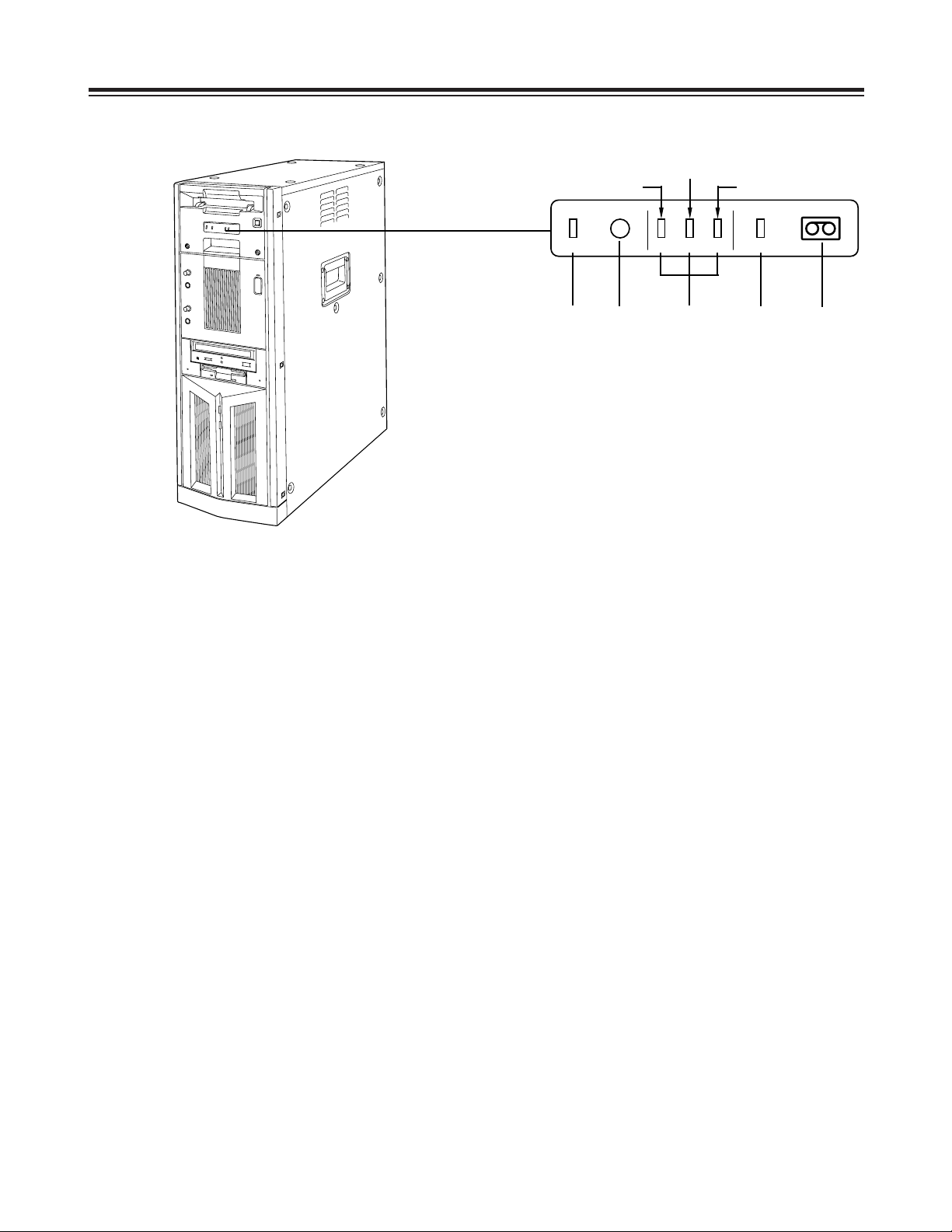
Parts and Their Functions
Front Panel
1
Main unit power switch
Set this switch to the OFF position after quitting the
system. If the power is turned off while the hard
disk drive is operating, data may be lost or the drive
may be damaged.
Do NOT turn off the power while white characters
on a blue background appear on the monitor
display (for the personal computer) during startup.
2
Main unit power LED
3
HDD sub switch
Press this switch if PC unit’s power does not come
on even when the main unit power switch is set to
ON.
Do not press this switch without good reason since
the power of the PC unit will be turned off if it
pressed while the power is supplied.
4
HDD reset switch
Press this switch when the PC unit is not operating
properly. The start screen will now be restored,
and checks on the operation can be carried out.
Do NOT press this switch while white characters on
a blue background appear on the monitor display
(for the personal computer) during startup.
5
Phones jack
The sound can be monitored when stereo
headphones are connected to this jack.
6
Phones volume control
This is used to adjust the headphones volume and
the monitor output volume.
7
Mic jack
The microphone is connected here for voice-over
editing operations.
8
Mic volume control
This is used to adjust the level at which the
microphone sound is input.
9
Cassette slot
M cassettes or L cassettes are loaded through this
slot. Consumer-use cassettes cannot be used for
recording or playback.
:
Cassette tape EJECT button.
When this button is pressed, the tape is unloaded,
and the cassette is automatically ejected several
seconds later.
;
CD-ROM drive
<
Tray OPEN/CLOSE button
=
Floppy disk drive
>
Carrying handle
?
HDD access display lamp (system)
@
HDD access display lamp (AV data)
A
Screws for securing mechanism
Loosen these screws when cleaning the head
mechanism transport system of the VTR unit or
when conducting other kinds of servicing or
maintenance. It will then be possible to pull out the
VTR unit’s mechanism.
After the maintenance work has been completed or
when the unit is to be moved, the mechanism must
be put back inside the unit and the screws
tightened up securely.
9
6
5
8
=
4
?
@
7
3
;
2
:
A
>
1
<
Page 7
– 7 –
Parts and Their Functions
LED Display Panel
1
AUTO OFF lamp
This lights when trouble has occurred in the unit’s
operation.
2
Warning lamp
This lights when a warning item has occurred.
3
Channel condition lamps
One of these lamps lights in accordance with the
error rate status.
(Green 5yellow 5amber)
Green: This lights when the video and audio play
signal error rates are at acceptable levels.
Yellow: This lights when either the video or audio
play signal error rate has deteriorated.
The playback picture remains normal even
while this lamp is lighted.
Amber: This lights when either the video or audio
play signal error rate is subject to
correction or interpolation.
4
VTR lamp
This lights while the tape is traveling.
5
Cassette loaded lamp
This lights when a cassette has been loaded in the
unit.
LED display panel
(Yellow)
(Amber)
(Green)
21345
AUTO OFF
W
CH CONDITION
VTR
Page 8
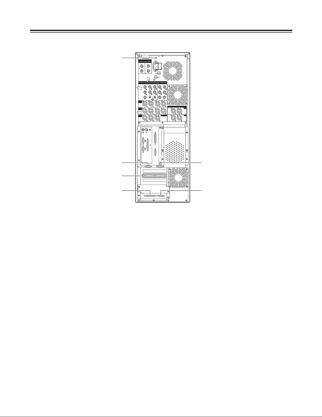
– 8 –
Parts and Their Functions
Rear Panel
1
AC power socket [~AC IN]
The power cord (provided) is connected to this
socket.
2
Fuse holder [FUSE 1/2, 125 V, 5 A]
This holder contains a 5 A fuse.
FUSE 1: for VTR unit
FUSE 2: for PC unit
3
Ventilating fan
This fan prevents the internal temperature from
rising. Do not block the fan openings by placing the
unit right up against a wall or other object.
4
Analog component video signal input
connectors [ANALOG, VIDEO INPUT, Y/P
B/PR
]
The analog component video signals are supplied
to these connectors. Connect a VTR or other video
unit with a component signal output capability here.
5
Analog composite video signal input connectors
[ANALOG, VIDEO INPUT, VIDEO IN]
The analog composite video signals are supplied to
these connectors which are joined by a loopthrough configuration. Connect a VTR or other
video unit with a composite signal output capability
here.
6
Analog reference video signal input connectors
[ANALOG, VIDEO INPUT, REF VIDEO IN]
The analog reference video signals are supplied to
these connectors which are joined by a loopthrough configuration.
In order to ensure that the video and audio signals
played back are stable, supply stable black burst
signals to these connectors from an external sync
signal generator.
7
75-ohm termination switch
Set this to ON for termination.
8
Serial digital video signal input connectors
[SDI/SDTI IN] (option)
(For details on supporting this option, consult your
dealer.)
9
Serial digital video signal output connectors
[SDI/SDTI OUT] (option)
(For details on supporting this option, consult your
dealer.)
AC IN
FUSE F1
125V
5A
FUSE F2
125V
5A
SIGNAL GND
IN OUT
1
2
SDI/SDIT
SDI/SDIT
ACTIVE THROUGH
SDI/SDIT
(OPTION)
SDI
Y
ANALOG
VIDEO INPUT VIDEO OUTPUT
Y1
2
AUDIO
IN
AUDIO
OUT
AUDIO
MON
TC IN
IN
OUT
DIGITAL AUDIO
MON
OUT
VIDEO
IN
REF VODEO
IN
P
B
P
R
P
B
P
R
ON
OFF
75≠
ON
OFF
75≠
CH1 CH2 CH3
PUSH
CH4
CH1 CH2
LR
RS-232C
SERIAL 1
SERIAL 2
RS-422A
CH1-2 CH3-4
CH3 CH4
PUSH PUSH PUSH PUSH
CH1-2 CH3-4
PUSH PUSH
8
4
9
2
1
3
3
3
3
7
5
6
Page 9
– 9 –
Parts and Their Functions
Rear Panel
:
Analog component video signal output
connectors [ANALOG, VIDEO OUTPUT, Y/P
B/PR
]
The analog component video signals are output
from these connectors. Connect a VTR or other
video unit with a component signal input capability
here.
;
Analog composite video signal output
connectors [ANALOG, VIDEO OUTPUT, 1/2]
The analog composite video signals are output from
these connectors.
Connect a VTR or other video unit with a composite
signal input capability here.
<
Analog video monitor signal output connector
[ANALOG, VIDEO OUTPUT, MON OUT]
The analog composite video signals with
superimposed data are output from this connector.
Connect an monitor (Video) for monitoring the
pictures here.
=
Analog audio signal input connectors
[ANALOG, AUDIO INPUT, CH1/CH2/CH3/CH4]
The analog audio signals are supplied to these
connectors. Connect a CD player, VTR or other
audio unit capable of outputting analog audio
signals to these connectors.
>
Analog audio signal output connectors
[ANALOG, AUDIO OUTPUT, CH1/CH2/CH3/CH4]
The analog audio signals are output from these
connectors. Connect an audio amplifier, VTR other
audio unit capable of handling analog audio signals
to these connectors.
?
Analog audio monitor signal output connectors
[ANALOG, AUDIO MON, L/R]
The audio playback signals are output from these
connectors. Connect monitor speakers, etc. to
them.
@
Time code signal input connector [TC IN]
This connector is used when the time code signals
from an external source are to be supplied.
AC IN
FUSE F1
125V
5A
FUSE F2
125V
5A
SIGNAL GND
IN OUT
1
2
SDI/SDIT
SDI/SDIT
ACTIVE THROUGH
SDI/SDIT
(OPTION)
SDI
Y
ANALOG
VIDEO INPUT VIDEO OUTPUT
Y1
2
AUDIO
IN
AUDIO
OUT
AUDIO
MON
TC IN
IN
OUT
DIGITAL AUDIO
MON
OUT
VIDEO
IN
REF VODEO
IN
P
B
P
R
P
B
P
R
ON
OFF
75≠
ON
OFF
75≠
CH1 CH2 CH3
PUSH
CH4
CH1 CH2
LR
RS-232C
SERIAL 1
SERIAL 2
RS-422A
CH1-2 CH3-4
CH3 CH4
PUSH PUSH PUSH PUSH
CH1-2 CH3-4
PUSH PUSH
:
=
;
<
@
>
?
Page 10
– 10 –
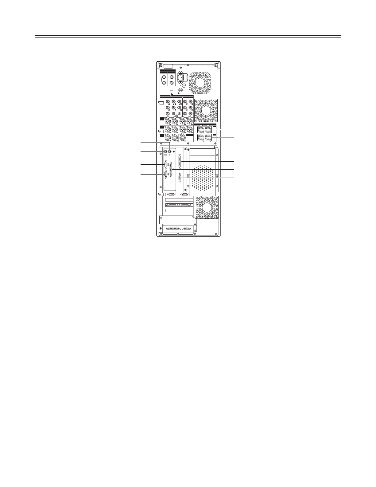
Parts and Their Functions
Rear Panel
A
Digital audio signal input connector
[DIGITAL AUDIO IN, CH1-2/CH3-4]
The digital audio signals in the AES/EBU format are
supplied to these connectors.
B
Digital audio signal output connectors
[DIGITAL AUDIO OUT, CH1-2/CH3-4]
Connect a VTR equipped with AES/EBU input
connectors here.
C
Serial 1 connector [SERIAL 1]
Spare connector
D
Mouse connector [MOUSE]
Connect the mouse (provided) here.
E
Keyboard connector [KEYBOARD]
Connect the keyboard (provided) here.
F
Parallel connector [PARALLEL]
Connect a device with a parallel interface here.
G
Serial 2 connector [SERIAL 2]
Spare connector
H
RS-232C connector [RS-232C]
Connect the editing pad here.
(Options supported: For details, please consult with
your dealer.)
I
RS-422A connector [RS-422A]
Connect an external VTR (External VTR1) which
can be controlled using an RS-422A interface to
control its recording and playback functions.
AC IN
FUSE F1
125V
5A
FUSE F2
125V
5A
SIGNAL GND
IN OUT
1
2
SDI/SDIT
SDI/SDIT
ACTIVE THROUGH
SDI/SDIT
(OPTION)
SDI
Y
ANALOG
VIDEO INPUT VIDEO OUTPUT
Y1
2
AUDIO
IN
AUDIO
OUT
AUDIO
MON
TC IN
IN
OUT
DIGITAL AUDIO
MON
OUT
VIDEO
IN
REF VODEO
IN
P
B
P
R
P
B
P
R
ON
OFF
75≠
ON
OFF
75≠
CH1 CH2 CH3
PUSH
CH4
CH1 CH2
LR
RS-232C
SERIAL 1
SERIAL 2
RS-422A
CH1-2 CH3-4
CH3 CH4
PUSH PUSH PUSH PUSH
CH1-2 CH3-4
PUSH PUSH
D
E
I
H
B
C
G
F
A
Page 11
– 11 –
Parts and Their Functions
Rear Panel
J
SCSI connector
Connect a SCSI hard disk drive for external
expansion purposes.
(Future plans call for this connector to be used to
support some options. For details, please consult
with your dealer.)
K
RS-232C connector
Spare connector (for maintenance purposes)
L
SVGA I/F connector
This is connected to the SVGA monitor.
M
SVGA I/F connector
Spare connector
N
RS-422A connector [RS-422A]
Connect an external VTR (External VTR2) which
can be controlled using an RS-422A interface to
control its recording and playback functions.
O
SIGNAL GND terminal
This is connected to the signal ground terminal on
the unit connected in order to reduce the noise.
It is not a safety ground.
AC IN
FUSE F1
125V
5A
FUSE F2
125V
5A
SIGNAL GND
IN OUT
1
2
SDI/SDIT
SDI/SDIT
ACTIVE THROUGH
SDI/SDIT
(OPTION)
SDI
Y
ANALOG
VIDEO INPUT VIDEO OUTPUT
Y1
2
AUDIO
IN
AUDIO
OUT
AUDIO
MON
TC IN
IN
OUT
DIGITAL AUDIO
MON
OUT
VIDEO
IN
REF VODEO
IN
P
B
P
R
P
B
P
R
ON
OFF
75≠
ON
OFF
75≠
CH1 CH2 CH3
PUSH
CH4
CH1 CH2
LR
RS-232C
SERIAL 1
SERIAL 2
RS-422A
CH1-2 CH3-4
CH3 CH4
PUSH PUSH PUSH PUSH
CH1-2 CH3-4
PUSH PUSH
M
L
J
K
N
O
Page 12

– 12 –
Connections
Basic Connections
(Connecting the power cord, keyboard, mouse and system cables)
1. Connect the keyboard and mouse to their respective connectors.
2. Connect the power cord.
AC IN
FUSE F1
125V
5A
FUSE F2
125V
5A
SIGNAL GND
IN OUT
1
2
SDI/SDIT
SDI/SDIT
ACTIVE THROUGH
SDI/SDIT
(OPTION)
SDI
Y
ANALOG
VIDEO INPUT VIDEO OUTPUT
Y1
2
AUDIO
IN
AUDIO
OUT
AUDIO
MON
TC IN
IN
OUT
DIGITAL AUDIO
MON
OUT
VIDEO
IN
REF VODEO
IN
P
B
P
R
P
B
P
R
ON
OFF
75≠
ON
OFF
75≠
CH1 CH2 CH3
PUSH
CH4
CH1 CH2
LR
RS-232C
SERIAL 1
SERIAL 2
RS-422A
CH1-2 CH3-4
CH3 CH4
PUSH PUSH PUSH PUSH
CH1-2 CH3-4
PUSH PUSH
Main unit
Power cord
Keyboard
Mouse
Page 13

– 13 –
Connections
Monitor Connections
$
Connecting the personal computer monitor (S-VGA)
Connect the computer monitor to the SVGA I/F connector. Use a monitor which meets the following
conditions.
Default settings
O
Resolution : 1152a870 pixels
O
Refresh frequency : 75 Hz
$
Connecting the monitor (Video) for monitoring the pictures
Connect the monitor (Video) for monitoring the pictures to the analog video monitor signal output (MON
OUT) connector. The pictures during recording and playback can now be checked.
AC IN
FUSE F1
125V
5A
FUSE F2
125V
5A
SIGNAL GND
IN OUT
1
2
SDI/SDIT
SDI/SDIT
ACTIVE THROUGH
SDI/SDIT
(OPTION)
SDI
Y
ANALOG
VIDEO INPUT VIDEO OUTPUT
Y1
2
AUDIO
IN
AUDIO
OUT
AUDIO
MON
TC IN
IN
OUT
DIGITAL AUDIO
MON
OUT
VIDEO
IN
REF VODEO
IN
P
B
P
R
P
B
P
R
ON
OFF
75≠
ON
OFF
75≠
CH1 CH2 CH3
PUSH
CH4
CH1 CH2
LR
RS-232C
SERIAL 1
SERIAL 2
RS-422A
CH1-2 CH3-4
CH3 CH4
PUSH PUSH PUSH PUSH
CH1-2 CH3-4
PUSH PUSH
Main unit
Cable with 15-pin (D-SUB)
connectors
S-VGA monitor for computer
Coaxial cable
(with BNC connectors)
monitor (Video) for
monitoring the pictures
MON OUT
Page 14

– 14 –
VTR Connections
Connect a commercial video cassette recorder/player
Connections
Note:
Set the TAPE/EE selector switch of the external VTR to the TAPE position. (If it is set to EE, the picture may
be unstable and audio may be transmitted.)
If the VTR is not equipped with a TAPE/EE selector switch, use one of the two connection configurations
described below:
1. To use the external VTR for playback only, connect the outputs of the external VTR to the inputs of the
editing system unit.
2. To use the external VTR for recording only, connect the inputs of the external VTR to the outputs of the
editing system unit.
AC IN
FUSE F1
125V
5A
FUSE F2
125V
5A
SIGNAL GND
IN OUT
1
2
SDI/SDIT
SDI/SDIT
ACTIVE THROUGH
SDI/SDIT
(OPTION)
SDI
Y
ANALOG
VIDEO INPUT VIDEO OUTPUT
Y1
2
AUDIO
IN
AUDIO
OUT
AUDIO
MON
TC IN
IN
OUT
DIGITAL AUDIO
MON
OUT
VIDEO
IN
REF VODEO
IN
P
B
P
R
P
B
P
R
ON
OFF
75≠
ON
OFF
75≠
CH1 CH2 CH3
PUSH
CH4
CH1 CH2
LR
RS-232C
SERIAL 1
SERIAL 2
RS-422A
CH1-2 CH3-4
CH3 CH4
PUSH PUSH PUSH PUSH
CH1-2 CH3-4
PUSH PUSH
Main unit
Coaxial cable
(with BNC connectors)
Coaxial cable
(with BNC connectors)
2-conductor shielded cable
(with XLR-3-12C connectors)
COMPONENT VIDEO OUT
(Y/P
B/PR
)
AUDIO OUT (CH1/CH2/CH3/CH4)
RS-422A
External VTR 1
(External VTR 2)
RS-422A
AUDIO IN (CH1/CH2/CH3/CH4)
COMPONENT VIDEO IN
(Y/PB/PR)
REFERENCE SIGNAL
REFERENCE VIDEO THROUGH OUT
Page 15

– 15 –
Audio Equipment Connections
Connect speakers with built-in amplifiers, a cassette deck or other audio unit.
Connections
AC IN
FUSE F1
125V
5A
FUSE F2
125V
5A
SIGNAL GND
IN OUT
1
2
SDI/SDIT
SDI/SDIT
ACTIVE THROUGH
SDI/SDIT
(OPTION)
SDI
Y
ANALOG
VIDEO INPUT VIDEO OUTPUT
Y1
2
AUDIO
IN
AUDIO
OUT
AUDIO
MON
TC IN
IN
OUT
DIGITAL AUDIO
MON
OUT
VIDEO
IN
REF VODEO
IN
P
B
P
R
P
B
P
R
ON
OFF
75≠
ON
OFF
75≠
CH1 CH2 CH3
PUSH
CH4
CH1 CH2
LR
RS-232C
SERIAL 1
SERIAL 2
RS-422A
CH1-2 CH3-4
CH3 CH4
PUSH PUSH PUSH PUSH
CH1-2 CH3-4
PUSH PUSH
Main unit
Cassette deck
AUDIO OUT
(CH1/CH2/CH3/CH4)
AUDIO MON L/R
AUDIO IN (CH1/CH2/CH3/CH4)
2-conductor shielded cable
(with XLR-3-12C connectors)
Speakers with built-in
amplifiers
2-conductor shielded cable
(with XLR-3-12C connectors)
Page 16

AC IN
FUSE F1
125V
5A
FUSE F2
125V
5A
SIGNAL GND
IN OUT
1
2
SDI/SDIT
SDI/SDIT
ACTIVE THROUGH
SDI/SDIT
(OPTION)
SDI
Y
ANALOG
VIDEO INPUT VIDEO OUTPUT
Y1
2
AUDIO
IN
AUDIO
OUT
AUDIO
MON
TC IN
IN
OUT
DIGITAL AUDIO
MON
OUT
VIDEO
IN
REF VODEO
IN
P
B
P
R
P
B
P
R
ON
OFF
75≠
ON
OFF
75≠
CH1 CH2 CH3
PUSH
CH4
CH1 CH2
LR
RS-232C
SERIAL 1
SERIAL 2
RS-422A
CH1-2 CH3-4
CH3 CH4
PUSH PUSH PUSH PUSH
CH1-2 CH3-4
PUSH PUSH
TO FADER PANEL
TO MAIN
~ AC IN
– 16 –
Connections
Editing Control Pad Connections
Connect the editing control pad (AJ-A77) available as an option.
Main unit
Connecting cable (25-pin)
provided with the AJ-A77
Power cord
AJ-A77
Note:
Turn on the power of the editing control pad (AJ-A77) after Windows NT has been started up in the main unit.
When the control pad’s power is turned on, all of its LED indicators will light up for about 1.5 seconds. The
control pad can then be operated by starting up the editing application program.
For details on how to set up and use the software for the AJ-A77, refer to the “AJ-A77 Operation Reference
Manual” which is provided with the Non-Linear Editing System Software Package.
Page 17

– 17 –
System Startup and Exit
System Startup
1
Set the power switches of the peripheral units
to ON.
2
Set the power switch on the main unit to ON.
The HDD access display lamp on the main
unit’s front panel lights.
Computer monitor/Windows NT startup screen
For details on video and audio uploading, editing and other operations, refer to the Reference Manual.
Main unit power switch
HDD access display lamp
3
The system starts up, and Windows NT also
starts up.
Page 18

– 18 –
2
Click if you wish to exit the system.
The Windows NT screen now appears.
System Exit
1
Click in the tool box.
A confirmation panel appears.
Confirmation panel
Computer monitor
System Startup and Exit
Tool box
Bin windowBin manager
Page 19

– 19 –
5
First, wait until the “It is now safe to turn off your
computer” message appears. Then set the power
switches of the main unit to OFF and, finally, set
the power switch on the peripheral units to OFF.
3
Click Windows NT shutdown.
A confirmation panel now appears.
4
Select the exit method and click if you
wish to exit Windows NT.
Computer monitor/Windows NT exit screen
Confirmation panel
System Startup and Exit
Page 20

– 20 –
If you believe that something is wrong with your product, take the time to check whether the product has been
operated incorrectly before asking a service engineer to conduct repairs.
1.Self-diagnosis test for main unit
The main unit’s basic test is automatically conducted when its power switch is set to the ON position. When
this test is completed without error, a beep will sound once.
If trouble has been detected, the beep will sound two or more times. In a case like this, the product may have
been installed improperly or a hardware error may be to blame.
2.Basic checks
Check out the following points.
1) Has the power cable been fully plugged into both the main unit and power outlet?
2) Have the power switches of the main unit, personal computer’s monitor and monitor (Video) for monitoring
the pictures all been turned on?
O
Are the power lamps on all the units lighted?
3) Is the personal computer’s monitor connected properly to the main unit?
Connect the monitor to the SVGA-I/F connector Lon page 11 of Parts and Their Functions.
(For details on the monitor connections, refer to page 13.)
4) Have the accessories been connected properly to the rear panel connectors?
(See page 12)
O
Included among the accessories are the keyboard and mouse.
O
The connectors for the keyboard and mouse have the same shape. Is the keyboard connected to the
mouse connector and is the mouse connected to the keyboard connector?
5) Have the contrast and brightness of the personal computer’s monitor and monitor (Video) for monitoring the
pictures been adjusted?
O
If no display appears, faulty adjustments may be to blame.
6) Has the system been started up with a floppy disk already inserted in the floppy disk drive?
O
When the main unit’s power switch is set to the ON position with a floppy disk already inserted in the
floppy disk drive, the main unit will attempt to start up the system from the floppy disk drive, resulting in a
startup failure.
3.Check out the Troubleshooting Chart
If the symptom persists even after the basic checks have been carried out, check the “Suggested remedial
action” for the symptom concerned on the following Troubleshooting Chart.
If the trouble still persists, contact your dealer.
Troubleshooting
Page 21

– 21 –
Symptom
$
Nothing at all appears on the
monitor screen or the “NO SIGNAL”
or other warning display appears.
Suggested remedial action
O
First, check whether the monitor is a PC/AT compatible monitor.
O
When nothing at all appears, check the supply voltage, connecting
cables (for disconnections) and monitor unit settings.
O
Some monitors have their own self-diagnosis functions. If you feel
that the monitor unit is responsible for the trouble, refer to the manual
accompanying the monitor, and check the adjustment and test
methods.
O
If you still cannot trace the cause of the problem, try replacing the
troubled monitor with a monitor whose operation is trouble-free if
such a monitor is at hand.
Troubleshooting Chart
Use the Troubleshooting Chart to remedy certain symptoms. Find the “Symptom” concerned in the left-hand
column of the table, and take the “Suggested remedial action” in the right-hand column.
Always make sure that you have conducted the basic checks before consulting the Table.
Symptoms related to personal computer monitor
$
The display keeps running off the
monitor screen.
O
Check the monitor’s resolution setting.
This product’s default resolution setting is 1152a870, and its default
refresh rate setting is 75 Hz.
These settings may not display properly on some monitors. Refer to
the manual accompanying the monitor, and check its available
resolution settings.
O
If you still cannot trace the cause of the problem, refer to the above
symptom (Nothing at all appears on the monitor screen or the “NO
SIGNAL” or other warning display appears), and check whether the
monitor is to blame for the problem.
Troubleshooting
$
The display on the monitor screen
is subject to wave-like noise,
distortion or jitter resulting in
horizontal or vertical wobbling.
O
If the monitor is determined by its self-diagnosis function to be
trouble-free, review the monitor’s installation location.
Trouble may be caused in the monitor display by the adverse affects
of magnetic fields generated by other devices (such as another
display, fluorescent light or transformer). In a case like this, turn off
the monitor, distance the monitor from the other devices, and turn the
power back on. (The picture distortion, etc. may remain if the monitor
is moved while the power is still supplied.)
Page 22

– 22 –
Symptom
$
The floppy disk drive’s access lamp
remains lighted or the system fails
to recognize the floppy disk drive.
Suggested remedial action
O
Has the product been started up with a floppy disk already inserted in
the floppy disk drive?
When its power switch is set to the ON position, this product checks
whether a floppy disk has already been inserted in the floppy disk
drive, and it then starts the product. If a floppy disk has not been
inserted, startup proceeds from the built-in system hard disk; if a disk
has been inserted, the product is started up from the floppy disk
drive.
For normal use, set the power switch to the ON position while there
is no floppy disk in the floppy disk drive: this will ensure that the
system starts up properly.
O
Check out the following points if this problem should occur while a
floppy disk has been inserted the floppy disk drive at times other than
startup.
1. Is the floppy disk damaged in any way?
(Check this using a trouble-free disk.)
2. Has the disk been inserted properly?
(Has it been inserted upside down?)
3. Does the editing application program lock up or does some other
software problem occur at the same time?
Symptoms related to floppy disk drive
Troubleshooting
Page 23

– 23 –
Symptom
$
All or some of the keys on the
keyboard fail to function.
Suggested remedial action
O
Are you using the keyboard provided with the product?
Problems may occur in operation if a keyboard other than the one
provided with the product is used.
O
Has the keyboard been connected?
O
Is the keyboard connected to the mouse connector and is the mouse
connected to the keyboard connector?
Provided that both the mouse and the keyboard used are the ones
provided with the product, connecting them erroneously will not
damage the main unit but input operations will not be acknowledged
even if the connections are rectified while the power is still being
supplied. In this case, the power must be turned off, the devices
must be connected properly and then the system must be re-booted.
Symptoms related to the keyboard or mouse
$
Desired letters or numbers cannot
be input from the keyboard.
O
Does the lighting of the [NumLock], [CapLock] and [ScrollLock] LEDs
reflect the desired status in each case?
The status of each of these LEDs is reversed every time the
corresponding key is pressed. If you have not noticed that a key has
been pressed in error, what you input may not be as originally
desired. Take [NumLock] for instance: the 10 number keys cannot
be used unless this LED is lighted.
$
The mouse fails to operate
properly.
O
Are you using the mouse provided with the product?
Problems may occur in operation if a mouse other than the one
provided with the product is used.
O
Has the mouse been connected.
O
Is the keyboard connected to the mouse connector and is the mouse
connected to the keyboard connector?
For the suggested remedial action, refer to the above symptom (All
or some of the keys on the keyboard fail to function).
$
The movements of the mouse
cursor are awkward.
O
Are you using the mouse provided with the product?
Problems may occur in operation if a mouse other than the one
provided with the product is used.
O
Is the mouse roller or mouse pad dirty?
$
The mouse cursor tends to
disappear or its display position
suddenly changes on its own.
O
Are you using the mouse provided with the product?
A mouse other than the one provided with the product may be more
susceptible to the effects of static or other types of noise.
Noise entering from the mouse or mouse connecting cable has the
effect of simulating mouse input and causing malfunctioning.
Troubleshooting
Page 24

– 24 –
Symptom
$
What is displayed as the memory
size differs from the size of the
memory actually provided.
$
At startup, the memory check
keeps running, and operation fails
to advance to the next step.
Suggested remedial action
O
Has the memory been increased inappropriately or has the memory
insertion slot been changed?
When the product is shipped, two 128 MB DIMM memory boards
yielding a total memory size of 256 MB are installed.
“262144 KB” appears as the memory check display during startup.
<Note>
When changing the memory board, consult your dealer and use the
memory board specified.
Symptoms related to memory
$
The main unit’s internal VTR
cannot be controlled from the
editing application program.
O
Has the system’s Internal VTR been selected as the setting for the
device to control the editing application program?
If any other setting (such as External VTR) has been selected for this
device, the internal VTR will not operate even when the on-screen
control buttons are clicked.
O
Has a tape been loaded into the main unit’s internal VTR?
The main unit’s internal VTR cannot be controlled when no tape has
been loaded into it or when its tape has been ejected.
$
The external VTR cannot be
controlled from the editing
application program.
O
Has the connecting cable for controlling the external VTR been
connected properly?
The external VTR cannot be controlled if the RS-422A 9-pin control
cable (option) has not been connected or if an error is made in the
connectors which have been connected.
For details on the connections, refer to the main unit’s rear panel
connection diagram. (See page 14)
O
Has “remote control” enable been set as the external VTR setting
mode?
For details on the remote control mode settings, refer to the manual
accompanying the external VTR.
O
Has External VTR been selected as the setting for the device to
control the editing application program?
If Internal VTR has been selected as the setting for this device, the
external VTR will not operate even when the on-screen control
buttons are clicked.
O
Has a tape been loaded into the external VTR?
The external VTR cannot be controlled when no tape has been
loaded into it or when its tape has been ejected.
Troubleshooting
Page 25

– 25 –
Symptom
$
A warning dialogue appears when
the display changes to the
Windows NT startup screen during
startup.
Suggested remedial action
O
Were the mouse and other peripheral devices connected after the
power was turned on?
If this is the case, the power must be turned off, the devices must be
connected properly and then the system must be re-booted.
O
Was the power turned off and then immediately turned back on?
Wait at least 5 seconds after turning the power off before turning it
back on.
Symptoms related to software, operating system or operations
$
The application program’s icon fails
to appear on the Windows NT
startup screen.
O
Has the system been started up in the VGA mode (640a480 screen
resolution) or has the screen resolution setting been changed?
O
Has the display size on the personal computer’s monitor been
adjusted so that the whole picture fits inside the display range?
The application program’s icon may be located outside the screen
display range.
O
Have you deleted the application program’s shortcut icon?
If the icon has been deleted in error, check inside the [trash folder],
and bring back the “Init Emv.exe” shortcut icon from it.
$
A warning dialogue appears when
the application program is started.
O
Is the AV hard disk recognized correctly by Windows NT?
Start the disk administrator on the Windows NT management menu,
and check the AV hard disk recognition status.
Troubleshooting
Page 26

– 26 –
Symptom
$
The playback images of the tape
inserted into the internal VTR are
not shown on the video monitor
(used to check the images) even
when the on-screen PLAY button is
clicked.
Suggested remedial action
O
Has the power of the monitor (Video) for monitoring the pictures
been turned on?
O
Has the monitor (Video) for monitoring the pictures cable been
connected properly?
O
Has the VTR tape been loaded?
O
Have images been recorded properly on the VTR tape?
O
Has “50Mx2, 50Mx1, 25Mx4” been selected for the device setting?
O
Do the tape format and device format match?
Other symptoms
$
Disk images cannot be uploaded.
O
Is there enough free memory on the AV disk?
The free memory left on the AV disk can be checked using the “Free”
display in the “Digitizer” editing program.
When the display reads “00:00:00:00,” it means that there is no free
memory left. The clips which are no longer required must be deleted
to free up the amount of memory needed.
$
Noise is superimposed onto the
disk images or some frames are
missing.
O
Has a program other than the designated editing application program
been installed?
The product may fail to operate properly if a program other than the
designated editing application program has been installed.
O
Is a program or programs other than the designated editing
application program being run?
O
Has the reference input been turned on or off?
O
In the case of uploaded data, is there a problem with the tape which
was used for uploading? Alternatively, does the VTR which was
used for recording have dirty heads?
$
The preview images of the internal
VTR break up frequently.
O
Is there a problem with the tape which was used?
O
Does the VTR have dirty heads?
The preview images of the internal VTR are not played back in the
complete on-track status. Some playback images may be disrupted.
Troubleshooting
Page 27

– 27 –
Symptom Suggested remedial action
Other symptoms
$
The personal computer’s monitor
screen display suddenly goes
completely blue during uploading.
O
Is the supply voltage within the rated range?
Use of an uninterruptible regulated power system is recommended
when the system is operated under adverse power supply conditions
including times when extreme voltage drops may occur.
$
When the power is turned on, the
alarm continues to sound
intermittently.
$
An abnormal odor or overheating is
noticeable.
$
Some other symptom occurs
unpredictably, and it is hard to
determine the cause.
O
Trouble may have occurred in the hardware.
Turn off the power and disconnect the power plug from the power
outlet.
$
No downloading possible.
O
Has a tape been loaded in the VTR?
O
Has “SAVE” (write prohibit) been set for the tape?
$
The indicator fails to operate
normally.
O
Trouble may have occurred in the hardware.
Turn off the power and disconnect the power plug from the power
outlet.
Troubleshooting
Page 28

– 28 –
VIDEO INPUT
Connector Signals
Y, PB, PR(ANALOG) : BNCa3
VIDEO IN : BNCa2 Loop-through, 75 Ω termination switch provided
REF VIDEO IN : BNCa2 Loop-through, 75 Ω termination switch provided
VIDEO OUTPUT
Y, PB, PR(ANALOG) : BNCa3
VIDEO OUT : BNCa2
MONITOR OUT : BNCa1 with superimposed data
AUDIO OUTPUT
AUDIO OUT (DIGITAL) : XLRa2 CH1-2, CH3-4, AES/EBU format
AUDIO OUT (ANALOG) : XLRa4 CH1, CH2, CH3, CH4
MONITOR OUT : XLRa2 L (CH1)/R (CH2)
HEADPHONES (front) : M6
TIME CODE INPUT
TC IN : XLRa1
AUDIO INPUT
AUDIO IN (ANALOG) : XLRa4 CH1, CH2, CH3, CH4
MIC IN (front) : M6
RS-232C
Pin No. Signal
1 GND
2 TXD
3 RXD
4 RTS
5 CTS
6 DSR
7SG
8 DCD
20 DTR
RS-422A
Pin No. Signal
1 GND
2 RXD –
3 TXD +
4 GND
5 spare
6 GND
7 RXD +
8 TXD –
9 GND
PARALLEL
Pin No. Signal
1 – STROBE
2~9 PD0~PD7
10 – ACK
11 BUSY
12 PE
13 SELECT
14 – AUTFD
15 – ERROR
16 – PINIT
17 – SL IN
18~25 GND
XLR
Pin No. Signal
1 GND
2 HOT
3 COLD
IN
PUSH
21
3
OUT
12
3
13
25
1
14
5
1
69
13
25
1
14
Page 29

– 29 –
Key board/Mouse
Pin No. Signal
1 DATA
2 un used
3 GND
4 + 5V
5 CLOCK
6 un used
SERIAL 1, 2
Pin No. Signal
1CD
2 RXD
3 TXD
4DTR
5 GND
6 DSR
7 RTS
8 CTS
9CI
RGB I/F
Pin No. Signal
1 CRV
2 CGV
3 CBV
4 un used
5~8 GND
9 + 5 V
10 GND
11 SDA
12 DCI Comm
13 – CHSYNC
14 – CVSYNC
15 SCL
Connector Signals
SCSI CH1/A, CH2/B
Pin No. Signal
1 + DB (12)
2 + DB (13)
3 + DB (14)
4 + DB (15)
5 + DB (P1)
6 + DB (0)
7 + DB (1)
8 + DB (2)
9 + DB (3)
10 + DB (4)
11 + DB (5)
12 + DB (6)
13 + DB (7)
14 + DB (P)
15 GND
16 DIFFSENSE
17, 18 TERM POWER
19 RESERVED
20 GND
21 + ATN
22 GND
23 + BSY
24 + ACK
25 + RST
26 + MSG
27 + SEL
28 + C/D
29 + REQ
30 + I/O
31 + DB (8)
32 + DB (9)
33 + DB (10)
34 + DB (11)
Pin No. Signal
35 – DB (12)
36 – DB (13)
37 – DB (14)
38 – DB (15)
39 – DB (P1)
40 – DB (0)
41 – DB (1)
42 – DB (2)
43 – DB (3)
44 – DB (4)
45 – DB (5)
46 – DB (6)
47 – DB (7)
48 – DB (P)
49, 50 GND
51, 52 TERM POWER
53 RESERVED
54 GND
55 – ATN
56 GND
57 – BSY
58 – ACK
59 – RST
60 – MSG
61 – SEL
62 – C/D
63 – REQ
64 – I/O
65 – DB (8)
66 – DB (9)
67 – DB (10)
68 – DB (11)
5
10
15
1
6
11
65
4
3
2
1
5
1
69
134
3568
Page 30

– 30 –
Error Items
When the WARNING lamp is lighted
Description
This is displayed when the fan motor stops.FAN STOP
Monitor display
VTR operation
Operation continues
This is displayed when the error rate increases and
correction/interpolation is performed on either the video or
audio playback signal.
HIGH ERROR RATE Operation continues
This is displayed when envelope levels approximately 1/3
that of normal levels are detected for more than one
second during playback, recording, or editing.
LOW RF Operation continues
This is displayed when the servo is not locked for three or
more seconds during playback, recording, or editing.
SERVO NOT LOCKED Operation continues
This appears during playback when a blank section (tape
blank) lasting for one or more seconds has been detected.
Such a section is identified as a tape blank when all of the
following conditions are met.
O No head outputs
O No playback data readout
O No CTL
NO RF Operation continues
When the AUTO OFF lamp is lighted
Description
If the capstan motor speed is abnormally low, the AUTO
OFF lamp lights, and the message display flashes.
CAP ROTATE TOO SLOW
Monitor display
VTR operation
STOP
(POWER OFF 5 ON)
If an abnormal tension at the supply side is detected in the
capstan mode, the AUTO OFF lamp lights, and the
message display flashes.
CAP TENSION ERROR STOP
(POWER OFF 5 ON)
If condensation is detected, the AUTO OFF lamp lights,
the message display flashes, and the VTR is transferred to
the eject mode. After the tape is ejected, the drum rotates
in order to eliminate the condensation.
When the condensation has been eliminated, the AUTO
OFF lamp and message display go off, and the VTR can
be used.
<Notes>
O If condensation is detected in the eject mode, the drum
starts rotating as soon as it is detected.
O If condensation is detected when the cassette has been
inserted, the drum rotation is stopped, and after the
tape is ejected, the drum starts rotating.
DEW EJECT
(Normal operation resumed
after condensation is
eliminated)
If the cylinder motor speed is abnormally high, the AUTO
OFF lamp lights, and the message display flashes.
DRUM ROTA TOO FAST STOP
(POWER OFF 5 ON)
Page 31

– 31 –
Error Items
When the AUTO OFF lamp is lighted
DescriptionMonitor display VTR operation
If the cylinder motor speed is abnormally low, the AUTO
OFF lamp lights, and the message display flashes.
DRUM ROTA TOO SLOW STOP
(POWER OFF 5 ON)
When it has been detected that the cylinder motor is
subject to an abnormal torque, the AUTO OFF lamp lights,
and the message display flashes.
DRUM TORQUE ERROR STOP
(POWER OFF 5 ON)
If the tape start and tape end are detected simultaneously
either during or after loading, the AUTO OFF lamp lights,
and the message display flashes.
E-FF STOP
(POWER OFF 5 ON)
The AUTO OFF lamp lights and the message display
flashes when the take-up reel has been rotating idly for a
fixed period of time while the start/end processing
operation during loading (half position) is being performed.
FRONT LOAD ERROR STOP
(POWER OFF 5 ON)
If the cassette does not move up even when 6 seconds
have elapsed since the VTR was transferred to the eject
mode, the AUTO OFF lamp lights, and the message
display flashes.
<Note>
If the cassette does not move down inside the machine
even when 6 seconds have elapsed since the cassette
was inserted, the VTR is transferred to the eject mode.
FRONT LOAD MOTOR STOP
(POWER OFF 5 ON)
When the unloading operation is not completed within 6
seconds, the AUTO OFF lamp lights, and the message
display flashes.
<Note>
When the loading operation is not completed within 6
seconds, the VTR is transferred to the eject (unloading)
mode.
LOADING MOTOR STOP
(POWER OFF 5 ON)
If the reel motor at the take-up side is running in the
reverse direction, the AUTO OFF lamp lights and the
message display flashes.
REEL DIR UNMATCH STOP
(POWER OFF 5 ON)
If an abnormal tension at the supply side is detected in the
reel mode, the AUTO OFF lamp lights, and the message
display flashes.
REEL TENSION ERROR STOP
(POWER OFF 5 ON)
When the servo microcomputer does not follow the
instructions of the system control microcomputer even
when 10 seconds have elapsed, the AUTO OFF lamp
lights, and the message display flashes.
SERVO COMM ERROR STOP
(POWER OFF 5 ON)
When there is no response from the servo microcomputer
for 1 or more seconds, the AUTO OFF lamp lights, and the
message display flashes.
SERVO CONTROL ERR STOP
(POWER OFF 5 ON)
When only the servo microcomputer was reset in an
instantaneous power failure, the AUTO OFF lamp lights,
and the message display flashes.
SERVO ERROR STOP
(POWER OFF 5 ON)
Page 32

– 32 –
Error Items
When the AUTO OFF lamp is lighted
DescriptionMonitor display VTR operation
If the start/end processing operation is not completed, the
AUTO OFF lamp lights, and the message display flashes.
S-FF/REW TIMEOVER STOP
(POWER OFF 5 ON)
If the supply reel motor should rotate at an abnormally fast
rate, the AUTO OFF lamp lights, and the message display
flashes.
S REEL TOO FAST STOP
(POWER OFF 5 ON)
If an abnormal torque applied to the supply reel motor is
detected or if an abnormal current flowing to the currentsensing resistor is detected, the AUTO OFF lamp lights,
and the message display flashes.
S REEL TORQUE ERR STOP
(POWER OFF 5 ON)
If the take-up reel motor should rotate at an abnormally
fast rate, the AUTO OFF lamp lights, and the message
display flashes.
T REEL TOO FAST STOP
(POWER OFF 5 ON)
If an abnormal torque applied to the take-up reel motor is
detected, the AUTO OFF lamp lights, and the message
display flashes.
T REEL TORQUE ERR STOP
(POWER OFF 5 ON)
If the tape has not been wound up during unloading, the
AUTO OFF lamp lights, and the message display flashes.
UNLOAD ERROR STOP
(POWER OFF 5 ON)
If, after the total tape amount has been detected, the
amount of tape wound up on the take-up reel and the
amount of tape supplied by the supply reel differ to an
abnormal extent while the tape is traveling in the forward
or reverse direction, the AUTO OFF lamp lights, and the
message display flashes.
WINDUP ERROR STOP
(POWER OFF 5 ON)
If, after the cassette has been inserted, the tape take-up
reel has not wound up the tape while the total tape amount
is not detected and while the tape is traveling in the
forward or reverse direction, the AUTO OFF lamp lights,
and the message display flashes.
W-UP REEL NOT ROTA STOP
(POWER OFF 5 ON)
Page 33

– 33 –
Maintenance and Care
O
In order to deliver a high performance, this unit contains some precision-made mechanisms.
To keep the unit in perfect working order for as long as possible, remember to maintain and take care of
this machine.
Lubrication, parts replacement, electrical component adjustment and servicing all require sophisticated
technology and equipment. Do not attempt to do any of these activities yourself but consult with your
dealer and follow the recommendations given.
O
Failure to remove dust and dirt accumulated inside the unit, replenish the lubricating oil, replace worn parts
(heads, etc.) and otherwise inspect and maintain your unit will not only make it impossible to achieve goodquality pictures and proper recordings but will also shorten the unit’s service life. It is recommended that
maintenance and inspections be performed as soon as they are required.
Video head Cleaning
This unit has an auto head cleaning function which automatically reduces the dirt on the heads. However, to
further increase the unit’s reliability, it is recommended that its video heads be cleaned every day.
Use the cleaning fluid designated by Panasonic.
Condensation
Condensation occurs due to the same principle involved when droplets of water form on a window pane of a
heated room. It occurs when the unit or tape is moved between places where the temperature or humidity
varies greatly or when, for instance:
O
It is moved to a very humid place full of steam or a room immediately after it has been heated up.
O
It is suddenly moved from a cold location to a hot or humid location.
When moving the unit to locations such as these, leave it standing for about 10 minutes rather than switching
on the power immediately.
If condensation has formed on or in the unit, the AUTO OFF lamp lights and the cassette tape is
automatically ejected.
Keep the power supplied and simply wait until the AUTO OFF lamp goes off.
Page 34

– 34 –
Specifications
[GENERAL]
Power supply: 120V AC(±10%), 50Hz – 60 Hz
Rated current: 4.0 A
CPU:
X86 compatible CPU
Operating system:
Windows NT 4.0
Memory:
256 MB
System hard disk drive:
EIDE type
AV hard disk drive:
Video: 18 GBa4, Audio: 18 GBa1
Recording for a nominal duration of 140 minutes is
possible. (With DVCPRO 50 format)
CD-ROM:
ATAPI specifications supported
Floppy disk drive:
3.5˝
[PC]
Sampling frequency:
48 kHz
Quantizing:
16 bits/sample
Number of channels:
4 channels (internal: 8 channels)
[AUDIO]
Sampling frequency:
Y: 13.5 MHz
PB/PR: 6.75 MHz (4:2:2)
PB/PR: 3.375 MHz (4:1:1)
Quantizing:
8 bits/sample
Compression:
DVCPRO 50/DVCPRO
[VIDEO]
Ambient operating temperature:
41 °F to 95 °F, (5 °C to 35 °C)
Ambient operating humidity:
10 % to 80 % (no condensation)
Dimensions (W) a(H) a(D):
9
1
/16˝ a25 1/4˝ a21 11/16˝ (230 a641 a550 mm)
Weight:
99.22 lb (45.1 kg)
main unit only
Recording format:
DVCPRO 50/DVCPRO format
Tape speed:
DVCPRO 50 (a2 speed)
: 135.280 mm/s
DVCPRO 50 (a1 speed)
: 67.640 mm/s
DVCPRO (a4 speed)
: 135.280 mm/s
Recording/playback time:
92 minutes :using AJ-5P92LP tape
(With DVCPRO 50 format)
[VTR]
Page 35

– 35 –
Specifications
$
Video input connectors
Analog composite:
BNCa2 (loop-through configuration)
Analog component (Y, PB, PR):
BNCa3
Analog reference video:
BNCa2 (loop-through configuration)
$
Video output connectors
Analog composite:
BNCa2
Analog component (Y, PB, PR):
BNCa3
Analog composite monitor:
BNCa1 (with superimposed data)
$
Audio input connectors
Analog (CH1/CH2/CH3/CH4):
XLRa4 (high impedance)
0 dBu
Mic:
M6 (variable level)
$
Audio output connectors
Analog (CH1/CH2/CH3/CH4):
XLRa4 (low impedance)
0 dBu
Digital (CH1-2/CH3-4):
XLRa2, AES/EBU format
Monitor (L/R):
XLRa2 (low impedance)
0 dBu
Headphones:
M6 (variable level), 8 Ω
$
Other connectors
Time code input:
XLRa1
External VTR control:
RS-422A (D-SUB, 9P) a2
Error report/Editing pad connection:
RS-232C (D-SUB, 25P) a2
[INPUT/OUTPUT CONNECTORS]
Page 36

F0201W1031
@
PANASONIC BROADCAST & TELEVISION SYSTEMS COMPANY
DIVISION OF MATSUSHITA ELECTRIC CORPORATION OF AMERICA
Executive Office:
3330 Cahuenga Blvd W., Los Angeles, CA 90068 (323) 436-3500
EASTERN ZONE:
One Panasonic Way 4E-7, Secaucus, NJ 07094 (201) 348-7621
Southeast Region:
1225 Northbrook Parkway, Ste 1-160, Suwanee, GA 30024 (770) 338-6835
Central Region:
1707 N Randall Road E1-C-1, Elgin, IL 60123 (847) 468-5200
WESTERN ZONE:
3330 Cahuenga Blvd W., Los Angeles, CA 90068 (323) 436-3500
Government Marketing Department:
52 West Gude Drive, Rockville, MD 20850 (301) 738-3840
Broadcast PARTS INFORMATION & ORDERING:
9:00 a.m. – 5:00 p.m. (EST) (800) 334-4881/24 Hr. Fax (800) 334-4880
Emergency after hour parts orders (800) 334-4881
TECHNICAL SUPPORT:
Emergency 24 Hour Service (800) 222-0741
Panasonic Canada Inc.
5770 Ambler Drive, Mississauga, Ontario L4W 2T3 (905) 624-5010
Panasonic de Mexico S.A. de C.V.
Av angel Urraza Num. 1209 Col. de Valle 03100 Mexico, D.F. (52) 1 951 2127
Panasonic Sales Company
Division of Matsushita Electric of Puerto Rico Inc.
San Gabriel Industrial Park, 65th Infantry Ave., Km. 9.5, Carolina, Puerto Rico 00630 (787) 750-4300
Printed in Japan
VQT9185-1
P
 Loading...