

Page 1
Digital Video Cassette Recorder
E
AJ-
EG
Operating Instructions
ENGLISHDEUTSCHFRANÇAISITALIANOESPAÑOL
Page 2
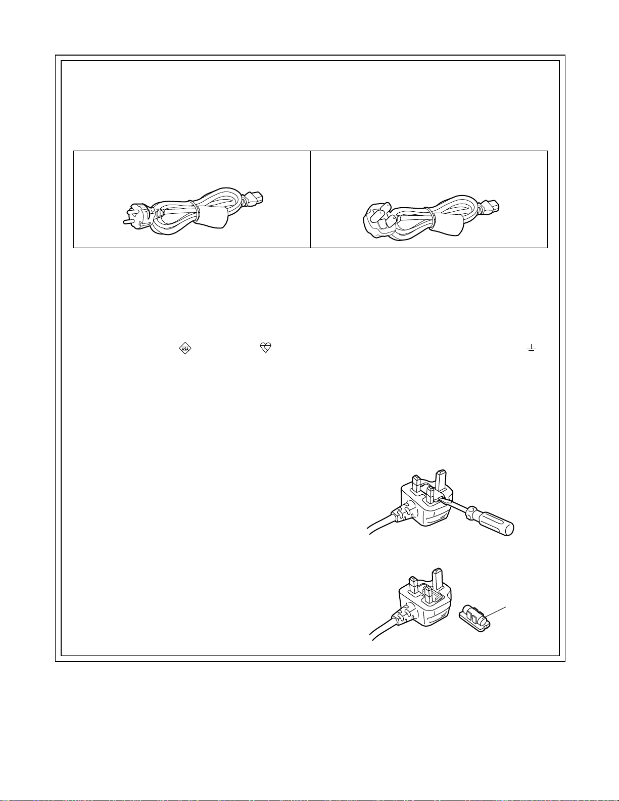
Caution for AC Mains Lead
FOR YOUR SAFETY PLEASE READ THE FOLLOWING TEXT CAREFULLY.
This product is equipped with 2 types of AC mains cable. One is for continental Europe, etc. and the other one is only for
U.K.
Appropriate mains cable must be used in each local area, since the other type of mains cable is not suitable.
FOR CONTINENTAL EUROPE, ETC.
Not to be used in the U.K.
FOR U.K. ONLY
This appliance is supplied with a moulded three pin
mains plug for your safety and convenience.
A 13 amp fuse is fitted in this plug.
Should the fuse need to be replaced please ensure that
the replacement fuse has a rating of 13 amps and that
it is approved by ASTA or BSI to BS1362.
Check for the ASTA mark or the BSI mark on the
body of the fuse.
If the plug contains a removable fuse cover you must
ensure that it is refitted when the fuse is replaced.
If you lose the fuse cover the plug must not be used
until a replacement cover is obtained.
A replacement fuse cover can be purchased from your
local Panasonic Dealer.
IF THE FITTED MOULDED PLUG IS UNSUITABLE
FOR THE SOCKET OUTLET IN YOUR HOME THEN
THE FUSE SHOULD BE REMOVED AND THE PLUG
CUT OFF AND DISPOSED OF SAFELY. THERE IS A
DANGER OF SEVERE ELECTRICAL SHOCK IF THE
CUT OFF PLUG IS INSERTED INTO ANY 13 AMP
SOCKET.
FOR U.K. ONLY
If the plug supplied is not suitable for your socket
outlet, it should be cut off and appropriate one fitted.
As the colours of the wires in the mains lead of this
appliance may not correspond with the coloured markings identifying the terminals in your plug, proceed as
follows:
The wire which is coloured GREEN-AND-YELLOW
•
must be connected to the terminal in the plug which is
marked with the letter E or by the Earth symbol or
coloured GREEN or GREEN-AND-YELLOW.
The wire which is coloured BLUE must be connected
•
to the terminal in the plug which is marked with the
letter N or coloured BLACK.
The wire which is coloured BROWN must be con-
•
nected to the terminal in the plug which is marked with
the letter L or coloured RED.
How to replace the fuse
1. Open the fuse compartment with a screwdriver.
If a new plug is to be fitted please observe the wiring
code as shown below.
If in any doubt please consult a qualified electrician.
WARNING: THIS APPLIANCE MUST BE EARTHED.
IMPORTANT: The wires in this mains lead are coloured
in accordance with the following code:
Green-and-Yellow:
Blue:
Brown:
Earth
Neutral
Live
2. Replace the fuse.
Fuse
2 (E)
Page 3

IMPORTANT
“Unauthorized recording of copyrighted television programmes, video tapes and other
materials may infringe the right of copyright
owners and be contrary to copyright laws.”
■
THIS APPARATUS MUST BE EARTHED
To ensure safe operation the three-pin plug must be
inserted only into a standard three-pin power point
which is effectively earthed through the normal
house-hold wiring.
Extension cords used with the equipment must be
three-core and be correctly wired to provide connection to earth. Wrongly wired extension cords are
a major cause of fatalities.
The fact that the equipment operates satisfactorily
does not imply that the power point is earthed and
that the installation is completely safe. For your
safety, if in any doubt about the effective earthing of
the power point, consult a qualified electrician.
WARNING:
TO REDUCE THE RISK OF FIRE OR
SHOCK HAZARD, DO NOT EXPOSE THIS
EQUIPMENT TO RAIN OR MOISTURE.
CAUTION:
TO REDUCE THE RISK OF FIRE OR SHOCK
HAZARD, AND ANNOYING INTERFERENCE,
USE THE RECOMMENDED ACCESSOIRES
ONLY.
ENGLISH
■
DO NOT REMOVE PANEL COVER BY
UNSCREWING
To reduce the risk of electric shock, do not remove
cover. No user serviceable parts inside. And do not
insert fingers or any other objects into the video
cassette holder.
CAUTION:
Do not install or place this unit in a bookcase,
built in cabinet or in another confined space in
order to keep well ventilated condition. Ensure
that curtains and any other materials do not
obstruct the ventilation condition to prevent
risk of electric shock or fire hazard due to
overheating.
is the safety information.
■ Do not insert fingers or any objects into the video
cassette holder.
■ Avoid operating or leaving the unit near strong
magnetic fields. Be especially careful of large audio
speakers.
This apparatus contains a lithium battery for memory back-up.
•
■ Avoid operating or storing the unit in an excessively
■ Do not spray any cleaner or wax directly on the unit.
■ If the unit is not going to be used for a length of time,
■ Do not leave a cassette in the recorder when not in
■ Do not block the ventilation slots of the unit.
■ Use this unit horizontally and do not place anything on
For the removal of the battery at the moment of the disposal at the end
•
hot, cold, or damp environment as this may result in
of the service life please consult your dealer.
damage both to the recorder and to the tape.
Do not throw away the battery. Instead, hand it in as hazardous waste.
•
Dit apparaat bevat een lithiumbatterij voor memory back-up.
•
protect it from dirt and dust.
Raadpleeg uw leverancier over de verwijdering van de batterij op het
•
moment dat u het apparaat bij einde levensduur afdankt.
use.
Gooi de batterij niet weg, maar lever hem in als KCA.
•
the top panel.
Attention/Attentie
CAUTION:
TO REDUCE THE RISK OF FIRE OR
SHOCK HAZARD, REFER MOUNTING OF
THE OPTIONAL BOARD TO QUALIFIED
SERVICE PERSONNEL.
Operating precaution
Operation near any appliance which generates
strong magnetic fields may give rise to noise in
the video and audio singals. If this should be
the case, deal with the situation by, for
instance, moving the source of the magnetic
fields away from the unit before operation.
■ Cassette tape can be used only for one-side, one
direction recording. Two-way or two-track recordings
cannot be made.
■ Cassette tape can be used for either Colour or Black &
White recording.
■ Do not attempt to disassemble the recorder.
There are no user serviceable parts inside.
■ If any liquid spills inside the recorder, have the recorder
examined for possible damage.
■ Do not use alcohol, benzine, paint thinners or any other
inflammable solvents to clean the unit’s external parts.
Contact by any of these solvents with the electrical
components inside the unit may cause a fire or electric
shock.
■ Refer any needed servicing to authorized service
personnel.
3 (E)
Page 4

Contents
General and Features ...............................................5
Controls and their functions ......................................7
• Front panel ..............................................................8
• Connector area .....................................................17
Connections .............................................................20
• Connections when one unit is used ......................20
• Connections when 2 units are used
(desk to desk) .....................................................21
• Connections with editing controller .......................22
• Connections for adjusting video output
(encoder output) signals .....................................23
Tapes .......................................................................24
Switching on the power/inserting the cassette .........25
STOP/STAND BY mode ..........................................26
Recording ................................................................27
Playback ..................................................................28
Jog/shuttle ...............................................................29
Manual editing .........................................................30
Preroll ......................................................................31
Automatic editing .....................................................32
• Switch settings and adjustments ...........................33
• Selecting the editing mode ....................................34
• Entering the edit points .........................................35
• Checking the edit points ........................................36
• Modifying the edit points .......................................37
• Preview .................................................................38
• Executing automatic editing ..................................39
• Review ..................................................................40
Audio split editing ....................................................41
V oice-over facility (internal) .....................................43
Audio cross channel editing (internal) .....................46
Multi cue ..................................................................48
Video output (encoder output)
signal adjustments ................................................53
Setup (default settings) ...........................................54
Setup menus............................................................55
• System menu ........................................................59
• User menu ............................................................61
• Basic menu .........................................................61
• Operation menu ..................................................63
• Interface menu ....................................................66
• Edit menu ............................................................70
• Tape protect menu ..............................................71
• Time Code menu ................................................72
• Video menu .........................................................74
• Audio menu .........................................................76
• V Blank menu .....................................................83
• Menu menu .........................................................89
Time code/user bit ...................................................90
• Recording internal/external time codes .................91
• Reproducing the time code/user bit ......................92
Superimpose screen ...............................................93
Video output signals and servo reference signal ....94
Audio V Fade Function ............................................96
Audio recording channel and monitor
output selection......................................................97
Printed circuit board ................................................98
Rack mounting ........................................................99
Video head cleaning ..............................................100
Condensation ........................................................100
Error messages .....................................................101
Table of AUTO OFF Error messages ....................104
RS-232C interface .................................................106
SDTI interface board ..............................................113
Connector signals .................................................116
Specifications ........................................................1 18
Before operating this unit, check that all of its accessories are present and accounted for.
Power cord....1 pc
Option
• Rack mounting adaptor AJ-MA75P
• Analog video input board AJ-YA955, AJ-YA956, AJ-YA957, AJ-YA958
• AJ-YAC960P SDTI interface board
• Audio memory unit AJ-YA752
4 (E)
Page 5

General and Features
This unit is a multi-purpose studio-use digital VTR which employs 1/4-inch wide compact
cassette tapes to enable recording, playback and editing with a high picture quality at the 50
Mbps video recording rate, and it is also capable of recording, playback and editing in the
existing DVCPRO (25 Mbps) format. Its 625/525 switching function makes this a studio video
cassette recorder which can be used anywhere in the world. In addition, it corporates digital
compression technology so that the deterioration in picture quality and sound quality
resulting from dubbing is significantly minimized.
The compact, lightweight 4U size makes carrying easier, even when mounted in a 19-inch
rack. The settings for the unit’s setup can be performed interactively while viewing the screen
menus on the TV monitor, and editing functions include both assemble and insert editing.
Features
Compact size and light weight
This is a 4U-size digital VTR. It can be mounted in a 19-inch rack with ease using the
optional rack-mounting adaptors (AJ-MA75P).
Up to 92 minutes of recording
Two sizes of cassette tapes can be used with this unit: M cassette (max. 33 minutes) and L
cassettes (max. 92 minutes). The width of the tapes measures 1/4 inch to achieve a compact
design.
ENGLISH
Superior Picture quality
Superior picture quality is delivered in the component signal recording mode.
Switchable 625i/525i
The video input signal switch (settings: 625i/525i) can be set to accommodate the recording
and playback of each type of signal.
SDI interface
This product’s standard features include 4:2:2 serial digital interface.
Compatibility with DVCPRO
This unit is capable of recording, playback and editing in the existing DVCPRO (25 Mbps)
format.
Compatibility with general consumer video equipment
Cassette tapes designed for general consumer applications containing material shot by a
consumer digital camera can be played back on this unit if the cassette adapter (optional
accessory, AJ-CS750P) is used.
<Note>
Tapes recorded in the LP consumer mode cannot be played back.
Digital slow motion/jog dial functions
Using Panasonic’s very own digital slow-motion technology, pictures played back in slow
motion at the following speeds can be reproduced clearly.
DVCPRO50 (50 Mbps): –1× to +2× speed
DVCPRO (25 Mbps): –1× to +2× speed
DV: –1× to +1× speed
DVCAM: –1× to +1× speed
5 (E)
Page 6

General and Features
Features
(continued)
Dial shuttle
Shuttle operations enable the tape to be played back with colour images at a speed of up to
32 times the forward and reverse direction.
Time codes
This unit comes with a built-in time code generator (TCG)/time code reader (TCR). In
addition to the internal time code, an external code input or input signal VITC can be
recorded on this VTR as the LTC time code.
Multifunctional interface
• Serial digital input/output
The component serial interface, a standard feature, allows for interfacing with component
signals in serial digital (SMPTE 259M-C/272M-A/EBU Tech.3267-E).
• Analogue video input/output
Composite and component signal outputs are provided as a standard feature, and
component (Y, PB, PR) and composite signal input interfacing is enabled by the use of an
analogue video input board (optional accessory).
• AES/EBU audio input/output
Digital audio input/output connectors are featured.
• SDTI input/output (option)
Use of the SDTI board (optional accessory) enables interfacing with component signals still
in their compressed form. (SMPTE 305M/321M)
• 9-pin (RS-422A)/(RS-232C) remote
In addition to the standard 9-pin serial remote (RS-422A), RS-232C and 25-pin parallel
remote connectors are also featured.
The RS-422A connector enables another VTR to be operated in parallel with the unit if a
looping connection is used for the two units.
4-channel high-sound-quality digital audio
The 4-channel PCM audio allows for not only independent editing and mixing on all four
channels. One channel is provided for the analogue CUE track.
Menu-driven setup
The setup settings, which are conducted prior to operating the unit are performed while
viewing the setup menus either on the unit’s display or a TV monitor.
6 (E)
Page 7
Controls and their functions
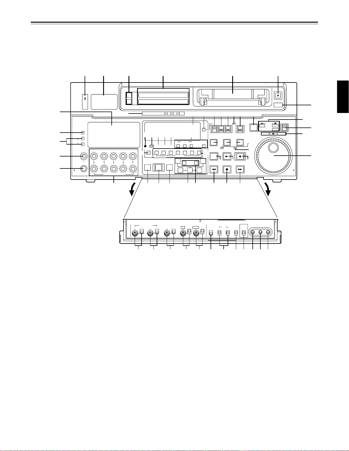
Front panel
qw e r t y
$4
$9
$8
$7
$6
ON
OFF
POWER
METER
FULL/FINE
L
MONITOR SELECT
R
LEVEL CH4 CUE
HEADPHONES
PULL
OPEN
CH1 CH2
CH3
PULL FOR VARIABLE
$5
u
VIDEO Y PB PR
AUDIO ANALOG
#9
W
#5
REC
PREVIEW
REVIEW
PB
INPUT SELECT
CMPST
AES/EBU USER SET
CH CONDITION
$0 $1 $2 $3
DVCPRO
ASMBL
VIDEO CH1
MULTI CUE
AUTO EDIT
SDTI(V&A)
SHIFT ADJ START RESET
SCH CF
CH2
CH3 CH4 CUE TC
4567321
INSERT
PREROLL
SDI
SDI
#8
TC SET
A
IN
–+
TRIM
SET OUTIN
TC MODE
CONTROL
TAPE
PLAYER
SERVO
PLAY
STOP
REMOTE
LOCAL
RECORDER
REC INHIBIT
REC
FF
TC INT
TC/CTL
UB EXT EE
STAND BY
!7 !8
EDIT
8
#6
A
OUT
REW
#2 #1 #0 #3 #4 !3 !1 !2
SET UP HUE
VIDEO LEVEL
PRESET
MANUAL
%0 %1 %2 %4 %5 %6 %9 ^0 ^1
CHROMA
PRESET PRESET PRESET PRESET
OUTIN
LEVEL
BLK
MANUAL MANUAL MANUALMANUAL
%3
CHROMA PH
4F/8F
CF
2F
TC
REGEN
REC RUN
PRESET FREE RUN
REC
INHIBIT
ON
OFF
TV
SYSTEM
525
625
%8%7
!0o!4
SLOW MOTION
@5@3@2@4@1@0!9#7
PUSH
JOG
REV FWD
!5
!6
MENU SET DIAG
EJECT
AUTO OFF
SHTL
SLOW
PULL
OPEN
@6
@8
i
@7
@9
ENGLISH
<Front Panel Top Section>
q POWER switch
w TV system/format displays
These displays indicate the type of TV system selected and tape format.
<625/525>
625: This lights when a 625 interlaced TV system is selected.
525: This lights when the 525 interlaced TV system has been selected.
<25Mbps/50Mbps>
25Mbps: This indicates the DVCPRO (25 Mbps) recording and playback mode. It also
indicates the DV and DVCAM playback mode.
In the DVCPRO (25 Mbps) recording and playback mode, this indicator lights in
tandem with the $1 DVCPRO (25 Mbps) cassette display lamp in the centre of
the front panel.
50Mbps: This indicates that the tape is recorded or played back in the DVCPRO50 (50
Mbps).
7 (E)
Page 8

Controls and their functions
e INPUT SELECT switches
These are used to select the video and audio input signals.
<Video>
Each time the VIDEO button is pressed, the input video signal selection is switched in the
order of Y/PB/PR, COMPOSITE, SDTI (V&A), SDI and then back to Y/PB/PR. When SDTI
(V&A) is selected, both video input and audio input are switched to SDTI.
<Audio>
Each time the AUDIO button is pressed, the input audio signal selection is switched in the
order of ANALOG, AES/EBU, USER SET, SDI and then back to ANALOG. USER SET is a
feature for independently selecting the input signals to record on PCM audio signal
channels 1 through 4, and is used together with the setup menu. However, when video
input is set to SDTI, audio input is also forcibly set to SDTI. For instance, if USER SET is
selected by INPUT SELECT and the channel selections are CH1=ANALOG on setup
menu No. 715, CH2=DIGITAL on No. 716, CH2=AES on No. 719, CH3=DIGITAL on No.
717, CH3=SIF on No. 720, and CH4=ANALOG on No. 718, then analogue input signals
are recorded on PCM audio signal CH1 on the tape, AES/EBU digital signals on CH2, SDI
input digital signals on CH3, and analogue input signals on CH4.
<Note>
The video or audio input selection mode established using the INPUT SELECT switch can
be selected using setup menu No. 112 (V IN SEL INH) or No. 113 (A IN SEL INH) setting.
r INPUT SELECT display
The characters corresponding to the selected input signal light up.
With the exception of analogue audio signals, the display flashes to alert the user when
the selected input signal is not supplied.
<Video>
Y PB PR: Analogue component video signal (option)
CMPST: Analogue composite video signal (option)
SDTI (V&A): Serial digital compressed video/audio signal (option)
SDI: Serial digital video signal (SMPTE 259M-C/EBU Tech.3267-E)
[The entire display lights when signal generation using the internal signal generator has
been selected for setup menu No. 600 (INT SG).]
<Audio>
ANALOG: Analogue audio signal
AES/EBU: Digital audio signal
USER SET: Selection of the audio signal to record
SDI: Serial digital audio signal (SMPTE 259M-C/272M-A)
[The entire display lights when signal generation using the internal signal generator has
been selected for setup menu No. 700 (INT SG).]
t Cassette insertion slot
y EJECT button
When this is pressed, the tape is unloaded and several seconds later the cassette is
automatically ejected. When the counter display indicates “CTL”, the display is reset.
Whether the EJECT button operation is to be enabled or disabled can be selected by
setting setup menu No. 115 (EJECT SW INH).
u Channel condition lamps
One of these lamps lights in accordance with the error rate status. (Green→Amber→Red)
Green: This lights when the error rates for the video and audio playback signals are
both acceptable.
Amber: This lights when the error rate for the video or audio playback signals has
deteriorated.
Red: The playback picture will remain normal even when this lamp lights.
This lights when the video or audio signals are subject to rectification or
interpolation.
i AUTO OFF lamp
This lights when trouble has arisen in the deck’s operation.
8 (E)
Page 9

Controls and their functions
<Front Panel Centre Section>
o PLAY button
Playback commences when this button is pressed.
Recording commences when the button is pressed together with the REC button; manual
editing commences when it is pressed together with the EDIT button during playback.
However, manual editing will not be initiated if the servo is not locked.
Pressing only the PLAY button during manual editing will cut out the editing and establish
the playback mode.
!0 REC button
Recording commences when this button is pressed together with the PLAY button.
When it is pressed during playback, search, fast forward or rewind, EE mode images and
audio signals can be monitored for as long as it is kept depressed.
When it is pressed in the stop mode, EE mode images and sound can be monitored.
When the STOP button is pressed, the original picture and sound are restored.
!1 STOP button
When this is pressed, the tape stops travelling, and if the TAPE/EE selector switch is at
TAPE, still pictures can be monitored.
The drum continues to rotate even in the stop mode, and the tape remains in close contact
with the drum.
If the stop mode continues for more than a certain period of time, either STANDBY OFF
mode or STEP FWD mode is automatically established to protect the tape. (Which mode
is to be established is set in setup menu items No. 400 through 403.)
The stop mode is established immediately after a cassette has been inserted into the unit.
ENGLISH
!2 FF button*
The tape is fast forwarded when this is pressed.
!3 REW button*
The tape is rewound when this is pressed.
!4 EDIT button
For manual editing, press both this button and the PLAY button together during playback.
When the button is pressed during playback, search*2, fast forward or rewind, the input
signals of the mode selected by the ASMBL or INSERT button can be monitored in the EE
mode for as long as the button is held down.
When the button is pressed in the stop mode, the input mode signals selected by the
ASMBL or INSERT button can be monitored in the EE mode.
The original picture and sound are restored when the STOP button is pressed.
!5 SERVO lamp
This lights when the drum servo and capstan servo have locked.
!6 REC INHIBIT lamp
This lights when the REC INHIBIT switch in the front panel bottom section is at ON or
when the accidental erasure prevention mode has been set for the cassette.
In this state, neither recording nor editing is possible.
Whether the REC INHIBIT lamp is to remain lit or flash when recording has been inhibited
by the accidental erasure prevention tab on the cassette tape can be selected by setting
setup menu No. 114 (REC INH LAMP).
1
1
*1The FF/REW speed can be selected on the setup menu No. 102 (FF. REW MAX), and it is
set to the same speed.
*2No guarantees are given for the audio playback sound in the search mode.
9 (E)
Page 10

Controls and their functions
<Front Panel Centre Section>
!7 STAND BY button
When this is pressed, the same tension as in the regular stop mode is applied to the tape,
and while the head drum continues to rotate, the button’s lamp lights to indicate that the
standby ON mode is established.
In the standby OFF mode, the half-loading mode is established.
When this button is pressed in the stop mode, the standby OFF mode is established, the
half-loading mode is established. The lamp in the button now goes off. When the unit
remains in the stop mode for longer than a predetermined period, the standby OFF mode
is automatically established in order to protect the tape.
When this button or the STOP button is pressed in the standby OFF mode, the standby
ON mode is established.
When a button other than the STOP button is pressed, the mode corresponding to the
button pressed is established.
On-screen settings are available for the transfer time to the standby OFF mode.
!8 PLAYER/RECORDER buttons
These buttons are operated when editing operations are conducted using the unit as the
recorder and a VTR equipped with an RS-422A serial interface remote control connector
(9 pins). Neither button functions when the unit is used on its own.
PLA YER button: When this button is pressed, its lamp lights, and the player con-
RECORDER button: When this button is pressed, its lamp lights, and the editing and
Both lamps light, and the recorder functions as the master unit for Parallel Run operations
if the PLAYER or RECORDER button is pressed while “ENA” has been selected for setup
menu No. 200 (PARA RUN). [However, external control can no longer be exercised from
the REMOTE connector (9-pin) when this setting has been made.]
nected to the unit can be operated by remote control. The unit’s
editing and tape transport buttons now control the player’s functions.
tape transport buttons control the recorder’s (= the unit’s) functions.
!9 TC/CTL switch
By pressing this switch, what appears on the counter display is changed between TC and
CTL.
When TC is selected, either the TC or UB value is displayed depending on the position
selected by the TC/UB switch.
@0 TC/UB switch
This selector switch determines whether the value of TC or UB appears on the counter
display when the TC/CTL switch has been set to TC.
@1 INT/EXT switch
INT: For using the built-in time code generator.
EXT: For using the time external code which is input from the time code input connector or
the video signal VITC. The selection is set at the setup menu No. 505 (EXT TC SEL).
@2 TAPE/EE switch
<In the stop mode>
TAPE: For outputting the signals played back from the tape.
EE: For outputting the input signals selected by the INPUT SELECT switch.
<In the editing*/recording mode>
TAPE: For outputting the simultaneous playback signals.
EE: For outputting the input signals selected by the INPUT SELECT switch.
*The SETUP menu No. 310 (CONFI EDIT) setting is required.
10 (E)
Page 11

Controls and their functions
<Front Panel Centre Section>
@3 REMOTE/LOCAL switch
This switch is set when the unit is to be controlled from an external source using the
REMOTE connector, RS-232C connector or parallel connector.
REMOTE: Set to this position when controlling the unit by a device connected using the
9-pin REMOTE connector or RS-232C/parallel connector.
LOCAL: Set to this position when controlling the unit using the controls on its own
operation panel.
Setup menu No. 211 (LOCAL 25P) can be used to make the selection when
the unit is to be controlled by the connected device using the PARALLEL
REMOTE connector with the switch at this position.
@4 REMOTE lamp
This lights when the REMOTE/LOCAL switch has been set to the REMOTE position.
@5 Search button
This button is pressed to establish the search mode.
When the search dial is set to the shuttle mode and turned to a particular position, and this
button is pressed, playback commences at the speed set by the search dial.
@6 JOG/SHTL/SLOW lamps
These indicate the present status of the search dial and SHTL/SLOW switch.
JOG: This lights when the unit is in the JOG mode.
SHTL: This lights when the unit is in the SHTL mode.
SLOW: This lights when the unit is in the VAR (variable) mode.
ENGLISH
@7 SHTL/SLOW switch
This selector switch is set when the search dial is used for SHTL or SLOW applications.
@8 REV/STILL/FWD lamps
One of these lamps lights depending on the operation of the search dial.
REV: This lights when the dial is turned counterclockwise and the tape travels in the
REV direction provided that the lamp in the search button has lit.
STILL: This lights in the JOG mode while the dial is kept stationary, and the tape stops
travelling provided that the lamp in the search button has lit.
It lights in the SHTL mode provided that the dial is at the STILL position.
FWD: This lights when the dial is turned clockwise, and the tape travels in the FWD
direction provided that the lamp in the search button has lit.
@9 Search dial
This is used to search for the edit points.
Each time it is pressed, the mode is alternately set to shuttle or jog, and one of the JOG,
SHTL and SLOW lamps lights. When the power has been turned on, the dial will not
function until it has first returned to the STILL position.
Shuttle mode: When the dial is turned and stopped at a particular position while the
SHTL/SLOW switch is at SHTL, the tape can be played back at the speed
corresponding to the dial’s rotary angle position. A still picture appears at
the dial’s centre position.
SLOW mode: When the dial is turned all the way counterclockwise with the SHTL/SLOW
switch at SLOW, the tape speed is set to –4.1× normal speed, when it is
set to the centre position, a still picture is produced, and when it is turned
all the way clockwise, the tape speed is set to +4.1× normal speed. The
speed for SLOW can be set using setup menu No. 320 (VAR FWD MAX)
and No. 321 (VAR REV MAX).
Jog mode: The dial’s clickstop positions are cleared, and the tape is played back at the
speed (see *1) that corresponds to the speed with which the dial is rotated.
*1Speed for each format
DVCPRO50 (50 Mbps): –1× to +2× speed
DVCPRO (25 Mbps): –1× to +2× speed
DV: –1× to +1× speed
DVCAM: –1× to +1× speed
11 (E)
Page 12

Controls and their functions
<Front Panel Centre Section>
#0 PREROLL button
This is used for feeding and cueing the tape for manual editing.
When it is pressed, the tape travels to the preroll point where it stops.
The preroll time can be set on the setup menu No. 000 (P-ROLL TIME).
When the PREROLL button is pressed while holding down the IN (A IN) or OUT (A OUT)
button, the tape can be cued up to the IN (A IN) or OUT (A OUT) point which has been
entered.
When the AUTO ENTRY on the setup menu No. 313 is set to “ENA”, IN point has been
entered at the point where the PREROLL button is pressed even if the IN point has not
been entered.
#1 AUTO EDIT button
Automatic editing is executed when this is pressed after an edit point has been entered.
When the AUTO EDIT button is pressed though the IN point has not been entered,
automatic editing is executed using the point at which the button was pressed as the IN
point.
#2 PREVIEW/REVIEW buttons
PREVIEW: When this is pressed after an edit point has been entered, the tape travels,
editing is not performed, and the preview can be activated on the screen
connected to the recorder.
If it is pressed when the IN point has not been entered, the point at which the
button was pressed is entered as the IN point, and preview is executed
accordingly.
REVIEW: If this is pressed after a block has been edited, the now edited block can be
played back and monitored on the screen connected to the recorder.
#3 IN (A IN)/SET/OUT (A OUT) buttons
When the SET button is pressed while holding down the IN (A IN) or OUT (A OUT) button,
the IN (A IN) or OUT (A OUT) point is entered.
A IN and A OUT are used during audio split editing to enter an audio IN or OUT point that
differs from the video In or OUT point.
While an IN (A IN) or OUT (A OUT) point is selected, the IN (A IN) or OUT (A OUT) button
corresponding to the point entered lights. When this button is pressed after a point has
been entered, the IN (A IN) /OUT (A OUT) point value appears on the counter display.
When the IN (A IN) or OUT (A OUT) button is pressed together with the RESET button, the
IN (A IN) or OUT (A OUT) point is cleared.
#4 TRIM buttons
These buttons are used to trim IN (A IN) or OUT (A OUT) point finely.
When the “+” or “–” button is pressed while the IN (A IN) or OUT (A OUT) button is held
down, the entered edit point can be trimmed in 1-frame increments. When the “+” button is
pressed, the tape is advanced by one frame; when the “–” button is pressed, it is rewound
by one frame.
#5 ASMBL button
This is pressed for assemble editing.
The button is self-illuminating, and it is set ON (lamp lights) when it is pressed once and
OFF (lamp goes off) when it is pressed again.
#6 INSERT buttons
Press one of these seven buttons to select the input signals to be edited during insert
editing.
The buttons are self-illuminating, and they are set ON (lamp lights) when they are pressed
once and OFF (lamp goes off) when they are pressed again.
#7 Counter display
This displays the TC and CTL count values, on-screen information and other messages.
12 (E)
Page 13

Controls and their functions
<Front Panel Centre Section>
#8 Time code buttons
These are used to set the TC or UB value.
SHIFT: When setting the TC or UB value, first press this button to stop the data running.
Change the digit now flashing on the display.
Each time the button is pressed, the flashing moves to the right by one digit, and
when it reaches the right-most digit, it returns to the left-most digit.
When it is kept depressed, the flashing moves consecutively.
ADJ: This is used to change the numeral of the digit now flashing on the display.
When the button is pressed once, the number is incremented by 1, and when it
is kept depressed, the number is incremented consecutively.
START: This enters the data which has been changed by the SHIFT and ADJ buttons.
Also, Pressing this button when the TC or UB value are not set enables the TCG
or UBG setting values to be confirmed.
RESET: When this button is pressed in the CTL mode, the display is reset to
“00:00:00:00”. In the CTL mode, the entered edit points are cleared.
In the TC/UB mode, the generator is reset when the button is pressed together
with the SHIFT button.
#9 Warning lamp
This lights to warn the operator of a particular item.
ENGLISH
$0 Cassette insertion display lamp
This lights when a cassette has been inserted into the unit.
$1 DVCPRO (25 Mbps) cassette playback display lamp
This lights when a cassette recorded in the DVCPRO (25 Mbps) is being played back.
$2 SCH lamp
This lights when the SCH phase of the external sync signal (REF VIDEO) or composite
input signal is within the designated range if the signal selected by the external synchronization of the video output signals is an external sync signal or composite input signal. In
the case of any other signal, it goes off.
$3 CF lamp
This lights when the colour framing is locked.
$4 Level meters
These indicate the respective levels of the PCM audio signals (CH1/CH2/CH3/CH4), CUE
track signal or the video signal*. The audio signal indicates the input signal levels during
recording and E-E selection, and the output signal levels during playback.
For video signal, the meters indicate the input signal levels only.
* CUE track signal or video signal is to be selected on setup menu No. 005 (METER
SELECT).
$5 Audio input/output level controls
These controls are used to adjust the recording and playback levels of the PCM audio
signals (CH1/CH2/CH3/CH4) and the CUE track signal. The upper controls are for
adjusting the recording levels. The lower controls are for adjusting the playback levels.
Each control is a “pull for variable” control, meaning that the level can be adjusted only
when the control has been pulled up. The signal levels are set to the unity value (preset
value) when the controls have been pushed down.
$6 Headphones jack
The sound being recorded, played back or edited can be monitored on stereo headphones when they are connected to this jack.
13 (E)
Page 14

Controls and their functions
<Front Panel Centre Section>
$7 Volume control
This is used to adjust the headphones volume and the monitor output volume.
Whether the headphones output and monitor output volumes are to be linked or kept
separate can be set on the setup menu No. 713 (MONI OUT). (Note that the headphones
output volume is normally linked.)
When the volumes are kept separate, the monitor output is set to the unity value (preset
value).
$8 MONITOR SELECT switches
These are used to select the audio signals output to the monitor L/R channels.
Each time the “L” button is pressed, the signals output to the monitor L channel are
selected in turn in the following order: CH1, CH2, CH3, CH4, CUE and back to CH1.
[However, this switching is disabled when CH1+2, CH3+4, CH1+3 or CH2+4 has been
selected for setup menu No. 729 (MONI MIX L).]
Each time the “R” button is pressed, the signals output to the monitor R channel are
selected in turn in the following order: CH1, CH2, CH3, CH4, CUE and back to CH1.
[However, this switching is disabled when CH1+2, CH3+4, CH1+3 or CH2+4 has been
selected for setup menu No. 730 (MONI MIX R).]
The L or R lamp on the level meter display lights to indicate which signal is now being
selected. [When the unit is set to “AUTO” in No. 721 (MONI CH SEL) on the setup menu,
then the display will change according to the monitor output.]
$9 METER (FULL/FINE) selector switch
This is used to change the scale display (graduations) of the audio level meters.
FULL mode: Standard scale (from –∞ to 0 dB)
FINE mode: The scale changes every 0.5 dB
14 (E)
Page 15

Controls and their functions
<Front Panel Bottom Section>
%0 VIDEO IN LEVEL control and switch
These are used to adjust the video input level.
PRESET: When the switch is set to “PRESET”, the video input level is set to the unity
value (0 dB).
MANUAL: When the switch is set to “MANUAL”, the video input level can be adjusted
using this control.
%1 VIDEO OUT LEVEL control and switch
When setup menu No. 10 (ENCODER SEL) is set to “LOCAL”, the video output level can
be adjusted.
When the switch is set to “PRESET”, the video output level is set to the unity value (0 dB).
When the switch is set to “MANUAL”, the video output level can be adjusted using this control.
%2 CHROMA LEVEL control and switch
When setup menu No. 10 (ENCODER SEL) is set to “LOCAL”, the chroma level can be
adjusted.
When the switch is set to “PRESET”, the chroma level is set to the unity value (0 dB).
When the switch is set to “MANUAL”, the chroma level can be adjusted using this control.
%3 BLACK LEVEL control and switch
When setup menu No. 10 (ENCODER SEL) is set to “LOCAL”, the black level can be
adjusted.
When the switch is set to “PRESET”, the black level is set to the unity value (0 IRE).
When the switch is set to “MANUAL”, the black level can be adjusted using this control.
ENGLISH
%4 CHROMA PHASE control and switch
When setup menu No. 10 (ENCODER SEL) is set to “LOCAL”, the chroma phase can be
adjusted.
When the switch is set to “PRESET”, the chroma phase is the unity value (0°).
When the switch is set to “MANUAL”, the chroma phase can be adjusted using this
control.
%5 CF switch
This selects whether the playback framing is to be locked in 4-field or 8-field increments or
2-field increments.
4F/8F: 625 mode: The framing is locked in 4- or 8-field increments. The framing can be
selected in either 4- or 8-field increments using setup menu No. 108
(CAP. LOCK).
525 mode: The framing is locked in 4-field increments.
2F: The framing is locked in 2-field increments.
%6 TC generator switch
REGEN: When the REGEN/PRESET switch is at REGEN, the internal time code
generator is synchronized with the time code which the time code reader
read from the tape. Whether to set TC or UB to REGEN can be selected at
the setup menu No. 503 (TCG REGEN).
PRESET: When the REGEN/PRESET switch is at PRESET, presetting is enabled by
the controls on the operation panel or by remote control.
REC RUN: The time code runs only during recording when the RUN MODE switch has
been set to REC. The time code runs constantly when the REGEN/PRESET
switch is set to REGEN.
FREE RUN: The time code runs regardless of the operation mode as long as the power
is being supplied when the RUN MODE switch has been set to FREE.
15 (E)
Page 16

Controls and their functions
<Front Panel Bottom Section>
%7 REC INHIBIT switch
This is used to inhibit or allow recordings on the video cassette tape.
ON: Recording on the tape is inhibited. At this setting, the REC INHIBIT lamp in the front
panel lights.
OFF: Recording on the tape is allowed provided that the accidental erasure prevention
tab on the video cassette tape enables recording to be conducted.
%8 TV SYSTEM selector switch
This selects the type of television system. The setting of this switch takes effect when the
power is turned off and then turned back on again.
625: 625 interlaced/50 Hz television system selection.
525: 525 interlaced/59.94 Hz television selection.
During recording, choose a signal input that corresponds to the 625i/525i selection.
During playback, choose a video cassette tape that corresponds to the 625i/525i selection.
%9 MENU button
When this is pressed, the setup menu appears on the TV monitor using VIDEO OUT 3
connector or SERIAL OUT 3 connector, and the setup menu No. appears on the display.
When it is pressed again, the menu setting mode is exited and the original operating mode
is restored.
^0 SET button
When this is pressed, the data which has been set on the setup menu is entered. After
data entry, the setup menu setting mode is exited and the original operating mode is
restored.
^1 DIAG button
When this is pressed, VTR information is displayed. When it is pressed again, the original
display is restored.
There are two types of VTR information: “HOURS METER” information and “WARNING”
information. Switching between these types is enabled by pressing the search button.
Indicated on the “HOURS METER” screen are serial number of the unit, the power-on
time, drum rotation time, tape travel time, loading count and power ON/OFF time, etc.
Indicated on the “WARNING” screen are the warnings.
16 (E)
Page 17
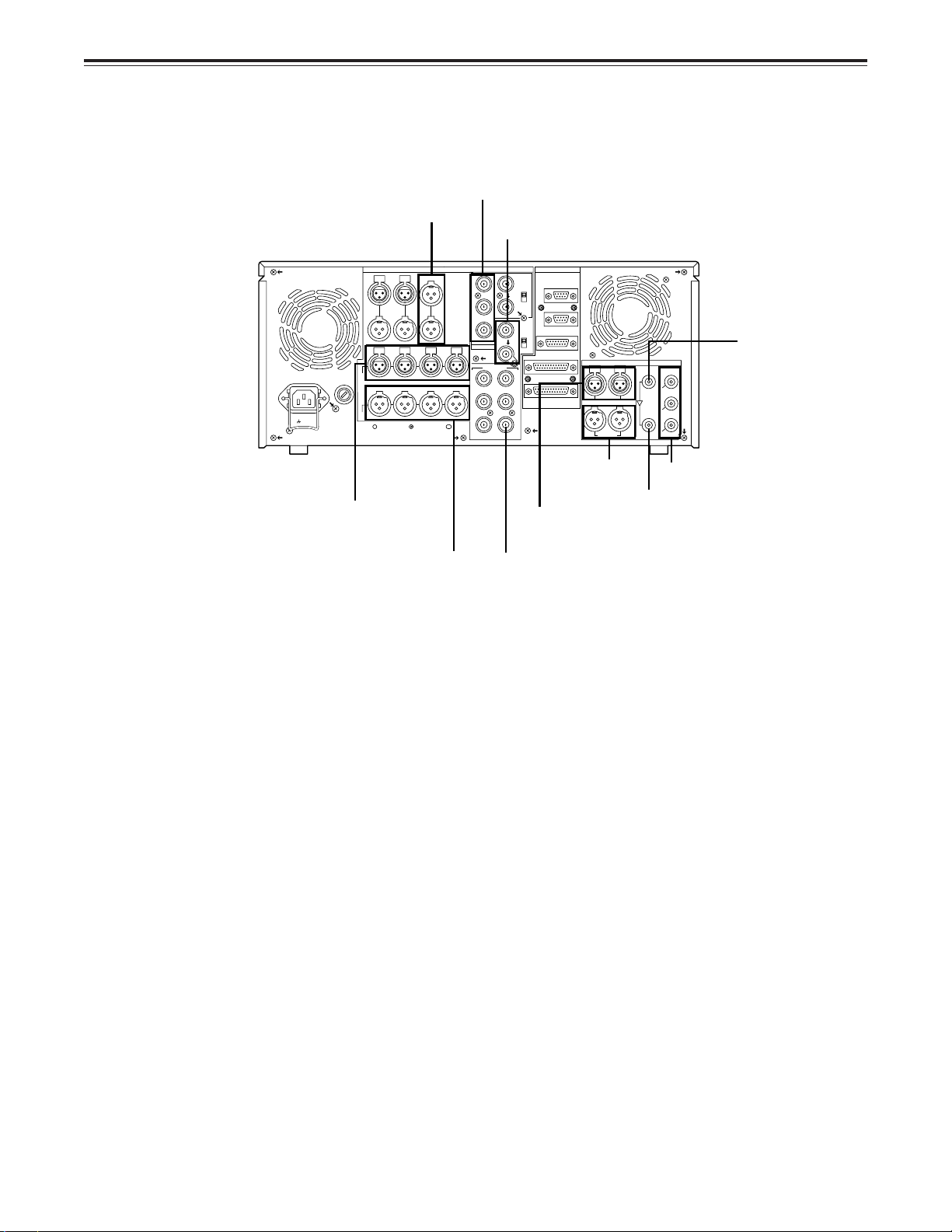
Controls and their functions
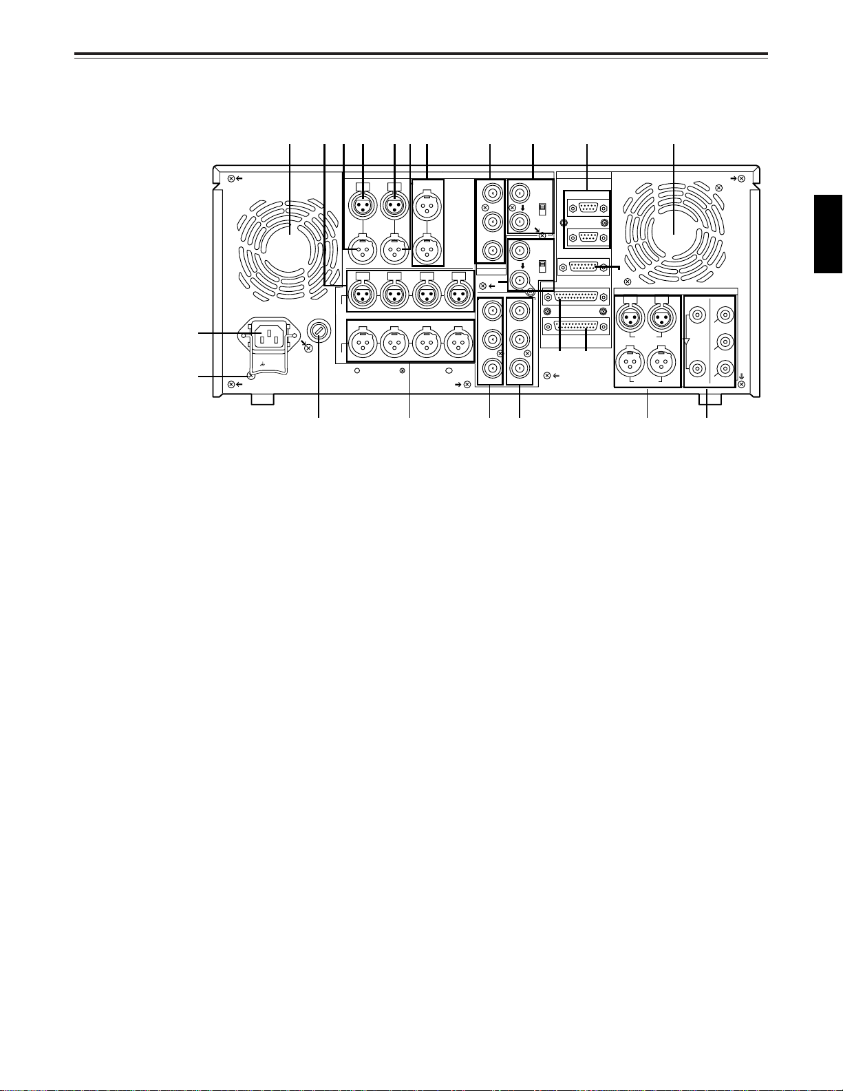
Connector area
rout!2!3!9r
!0 y i
q
w
SIGNAL
GND
~AC IN
TC
IN
OUT OUT
L
IN
R
CH3 CH4
CH2CH1
Y
P
B
P
R
OPTION
ANALOG
MON
CUE
!4
AUDIO
IN
CH2CH1 CH3 CH4
AUDIO
OUT
e!1
Y
P
B
P
R
!5 !6 !7 !8
VIDEO OUT
(SUPER)
1
2
(WFM)
3
VIDEO
IN
ON
75Ω
OFF
REF VIDEO
IN
ON
75Ω
OFF
REMOTE
REMOTE IN/OUT
REMOTE OUT
ENCODER REMOTE
RS-232C
PARALLEL
@1 @2
@0
PUSH
CH 1/2 CH 3/4
AUDIO IN
CH 1/2 CH 3/4
AUDIO OUT
PUSH
DIGITAL
SERIAL
IN
SDI/
SDTI
(
OPTION
)
SERIAL
OUT
1
SDI/
(
SDTI
2
SDI
3
SDI
(
SUPER
OPTION
)
ENGLISH
)
17 (E)
Page 18

Controls and their functions
<Connector area>
q AC IN connector
This is for connecting the unit to the power outlet using the power cord provided.
w SIGNAL GND terminal
This terminal is connected to the signal ground terminal of the connected unit in order to
reduce noise. It is not connected to ground for safety purposes.
e Fuse holder
This contains a fuse.
r Fan motor
This is for cooling the unit.
The W lamp lights when trouble has caused the fan motor to stop. If the unit is still
operated in the warning status, the temperature inside the deck will rise, and when it
exceeds the safety temperature, all the unit’s operations will be shut down.
t TIME CODE IN connector
This is the connector for recording the external time code on the tape.
y TIME CODE OUT connector
The playback time code is output from this connector during playback.
During recording, the time code generated by the internal time code generator is output.
u CUE IN connector
The analogue signal to be recorded on the CUE track is supplied to this connector. The
audio signals from a microphone can also be recorded by selecting the –60 dB input mode
on the setup menu No. 705 (CUE IN LV).
i CUE OUT connector
The analogue signal recorded on the CUE track is output from this connector.
o MONITOR OUT connector
During playback, the playback signals from the CUE track or PCM audio signal CH1/CH2/
CH3/CH4 are output from this connector.
!0 ANALOG AUDIO IN connectors
These are the analogue audio input connectors.
!1 ANALOG AUDIO OUT connectors
The analogue audio signals are output from these connectors.
!2 ANALOG COMPONENT VIDEO IN connector (option)
The analogue component video signal is supplied to this connector.
!3 ANALOG COMPOSITE VIDEO IN connectors and 75Ω termination switch (option)
The analogue composite video signal is supplied to these two connectors which are
connected in a loop-through configuration. When the termination is required, set the
switch to ON.
!4 REF VIDEO IN connectors and 75Ω termination switch
These are the input connectors for the reference video signals. Supply signals with colour
burst. When the termination is required, set the switch to ON.
18 (E)
Page 19

Controls and their functions
<Connector area>
!5 ANALOG COMPONENT VIDEO OUT connector (option)
The analogue component video signal is output from this connector.
!6 ANALOG COMPOSITE VIDEO OUT connectors
The analogue composite video signals are output from these connectors.
The video signal with signals superimposed on it can be output from the VIDEO OUT 3
connector.
The superimpose function can be set ON or OFF on the setup menu No. 007 (SUPER).
!7 DIGITAL AUDIO IN/OUT connector
This I/O connector is for digital audio signals which comply with the AES/EBU standard.
!8 SERIAL DIGITAL COMPONENT AUDIO/VIDEO IN/OUT connector
This I/O connector is for digital component audio and video signals which comply with the
SMPTE 259M-C/272M-A/EBU Tech.3267-E standard.
The SERIAL OUT 3 connector can output the video signal containing superimposed data.
The superimposed data can be set ON/OFF using setup menu No. 007 (SUPER).
<Note>
When the SDTI board (optional accessory) is used, SERIAL IN is used for the SDTI/SDI
common input signal while SERIAL OUT1 is used for the SDTI/SDI common output signal.
For further details, refer to the operating instructions accompanying the model AJY AC960P SDTI interface board.
!9 Remote control connectors
The unit can be controlled from an external source by connecting the unit with another unit
or an external controller.
There are two remote control connectors, one for IN/OUT uses and the other for OUT
uses.
IN/OUT: For connection with an external controller.
For connection with deck-to-deck operation.
OUT: For connection with parallel running operations.
For use in a loop-through configuration.
<Note>
To connect the unit to the OUT connector when performing deck-to-deck operations where
this unit is used as the recorder, selection can be made using setup menu No. 212
(MASTER PORT).
ENGLISH
@0 ENCODER REMOTE connector
The external encoder/controller is hooked up to this connector when the video output
signal and other settings are to be adjusted from an external source.
@1 RS-232C connector
@2 PARALLEL REMOTE connector
This is used when operating the unit from an external source.
19 (E)
Page 20
Connections
Connections when one unit is used
Set the CONTROL switch on the front panel to LOCAL.
Audio monitor output connectors
Analog video input connectors (option)
Reference input connectors
~AC IN
SIGNAL
GND
Analog audio input connectors
Analog audio output connectors
OUT OUT
AUDIO
IN
AUDIO
OUT
CUE
MON
INTCIN
L
R
CH2CH1 CH3 CH4
CH2CH1 CH3 CH4
ANALOG
REMOTE
VIDEO
Y
IN
REMOTE IN/OUT
ON
75Ω
P
B
P
R
Y
P
B
P
R
OPTION
VIDEO OUT
(SUPER)
OFF
REMOTE OUT
REF VIDEO
IN
ENCODER REMOTE
ON
75Ω
OFF
1
2
(WFM)
3
RS-232C
PARALLEL
PUSH
CH 1/2 CH 3/4
AUDIO IN
CH 1/2 CH 3/4
AUDIO OUT
Digital audio
output
connector
Digital audio
input connector
Video monitor output connectors
DIGITAL
SERIAL
SERIAL
PUSH
OUT
IN
1
SDI/
(
)
SDTI
OPTION
SDI/
(
)
SDTI
OPTION
2
SDI
3
SDI
(
)
SUPER
Digital audio/video output
Active through output
connector
Digital audio/video
input connector
20 (E)
Page 21
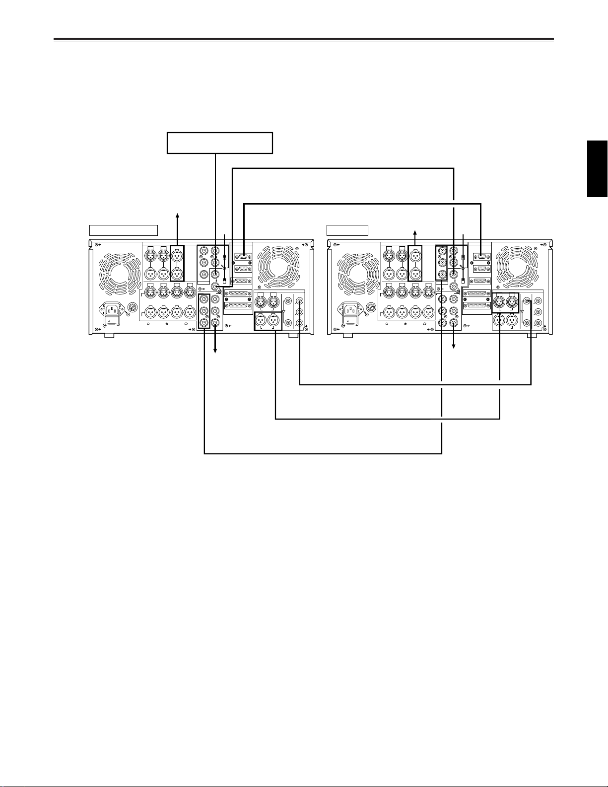
Connections
Connections when 2 units are used (deck to deck)
Source machine: Set the CONTROL switch on the front panel to REMOTE.
Recorder: Set the CONTROL switch on the front panel to LOCAL.
Reference Signal generator
To audio monitor
Source machine
IN
OUT OUT
AUDIO
~AC IN
SIGNAL
GND
IN
AUDIO
OUT
device
MON
CUEINTC
L
R
CH2CH1 CH3 CH4
CH2CH1 CH3 CH4
ANALOG
Remote control signal (9P)
To audio monitor
IN
OUT OUT
AUDIO
IN
AUDIO
OUT
device
MON
CUEINTC
L
R
CH2CH1 CH3 CH4
CH2CH1 CH3 CH4
ANALOG
OFF ON
REMOTE
VIDEO
Y
IN
REMOTE IN/OUT
ON
75Ω
P
B
OFF
P
R
OPTION
VIDEO OUT
Y
P
B
P
R
REMOTE OUT
REF VIDEO
IN
ENCODER REMOTE
ON
75Ω
OFF
RS-232C
1
PARALLEL
2
(WFM)
3
(SUPER)
PUSH
AUDIO OUT
DIGITAL
PUSH
CH 1/2 CH 3/4
AUDIO IN
CH 1/2 CH 3/4
SERIAL
SERIAL
OUT
IN
1
SDI/
(
SDTI
OPTION
SDI/
(
)
SDTI
OPTION
2
SDI
3
SDI
(
)
SUPER
)
Recorder
~AC IN
SIGNAL
GND
To video
monitor device
Digital video/audio signal
Digital audio
Analog video signal (component)
[When the analog video input board
(option) has been installed]
Y
P
B
P
R
OPTION
VIDEO OUT
1
Y
P
2
B
(WFM)
P
3
R
(SUPER)
REMOTE
VIDEO
IN
REMOTE IN/OUT
ON
75Ω
OFF
REMOTE OUT
REF VIDEO
IN
ENCODER REMOTE
ON
75Ω
OFF
RS-232C
PARALLEL
To video
monitor
device
PUSH
CH 1/2 CH 3/4
AUDIO IN
CH 1/2 CH 3/4
AUDIO OUT
ENGLISH
DIGITAL
SERIAL
SERIAL
PUSH
OUT
IN
1
SDI/
(
)
SDTI
OPTION
SDI/
(
)
SDTI
OPTION
2
SDI
3
SDI
(
)
SUPER
21 (E)
Page 22
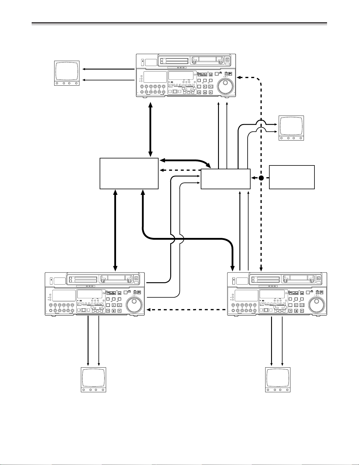
Connections
Connections with editing controller
Recorder
AV monitor
Video monitor signals
Audio monitor signals
Editing controller
ON
OFF
POWER
METER
FULL/FINE
L
MONITOR SELECT
R
LEVEL CH4 CUE
HEADPHONES
PULL
OPEN
VIDEO Y PB PR
AUDIO ANALOG
CH1 CH2
CH3
PULL FOR VARIABLE
To REMOTE IN/OUT
connector
Remote
INPUT SELECT
SDI
CMPST
SDTI(V&A)
AES/EBU USER SET
SDI
CH CONDITION
SHIFT ADJ START RESET
SCH CF
DVCPRO
W
CH2
CH3 CH4 CUE TC
ASMBL
VIDEO CH1
4567321
INSERT
MULTI CUE
REC
PB
A
PREVIEW
AUTO EDIT
IN
REVIEW
PREROLL
TC SET
–+
TRIM
SET OUTIN
TC MODE
CONTROL
TAPE
TC INT
TC/CTL
UB EXT EE
PLAYER
RECORDER
STAND BY
SERVO
EDIT
PLAY
8
A
OUT
STOP
REW
EJECT
AUTO OFF
PUSH
REMOTE
SHTL
JOG
SLOW
REV FWD
LOCAL
REC INHIBIT
REC
FF
SLOW MOTION
PULL
OPEN
AV monitor
Video input signals
Audio input signals
Video monitor signals
Audio monitor
signals
Reference
AV switcher
signal generator
CH1 CH2
CH3
PULL FOR VARIABLE
VIDEO Y PB PR
AUDIO ANALOG
REC
PB
W
PREVIEW
REVIEW
CH CONDITION
ASMBL
ON
OFF
POWER
METER
FULL/FINE
L
MONITOR SELECT
R
LEVEL CH4 CUE
HEADPHONES
PULL
OPEN
Source machine
Video monitor
INPUT SELECT
CMPST
SDTI(V&A)
AES/EBU USER SET
SCH CF
DVCPRO
VIDEO CH1
MULTI CUE
AUTO EDIT
signals
SHIFT ADJ START RESET
CH2
CH3 CH4 CUE TC
4567321
INSERT
PREROLL
SDI
SDI
TC SET
A
IN
8
–+
TRIM
SET OUTIN
TC/CTL
A
OUT
Remote
To REMOTE
IN/OUT connector
TC MODE
CONTROL
REMOTE
LOCAL
RECORDER
REC INHIBIT
PUSH
JOG
REV FWD
REC
FF
SLOW MOTION
TAPE
TC INT
UB EXT EE
PLAYER
STAND BY
SERVO
EDIT
PLAY
STOP
REW
Audio monitor
signals
Audio output
Video output signals
signals
Remote
Reference signal
Audio output signals
Video output signals
To REMOTE
IN/OUT connector
REMOTE
LOCAL
REC INHIBIT
REC
EJECT
AUTO OFF
PUSH
SHTL
JOG
SLOW
REV FWD
FF
SLOW MOTION
PULL
OPEN
EJECT
AUTO OFF
SHTL
SLOW
PULL
OPEN
Reference signal
ON
OFF
POWER
METER
FULL/FINE
L
MONITOR SELECT
R
LEVEL CH4 CUE
CH1 CH2
HEADPHONES
PULL
PULL FOR VARIABLE
OPEN
INPUT SELECT
W
PREVIEW
REVIEW
CH CONDITION
ASMBL
CMPST
SDTI(V&A)
AES/EBU USER SET
SCH CF
DVCPRO
VIDEO CH1
MULTI CUE
AUTO EDIT
SHIFT ADJ START RESET
CH3 CH4 CUE TC
CH2
4567321
INSERT
PREROLL
SDI
SDI
TC SET
–+
TC MODE
CONTROL
TAPE
TC INT
TC/CTL
UB EXT EE
PLAYER
RECORDER
STAND BY
SERVO
EDIT
PLAY
8
A
OUTAIN
TRIM
STOP
REW
SET OUTIN
VIDEO Y PB PR
AUDIO ANALOG
CH3
REC
PB
Source machine
Audio monitor
Video monitor
signals
signals
AV monitorAV monitor
22 (E)
<Note>
When an editing controller
made by CMX is used,
support must be provided at
the editing controller side.
Page 23

Connections
Connections for adjusting video output (encoder output) signals
Player 1
REF
(BB)
REF
VIDEO IN
(source machine 1)
INPUT SELECT
SDI
VIDEO Y PB PR
CMPST
ON
OFF
POWER
METER
FULL/FINE
L
MONITOR SELECT
R
LEVEL CH4 CUE
HEADPHONES
PULL
OPEN
SDTI(V&A)
AUDIO ANALOG
AES/EBU USER SET
SDI
CH CONDITION
TC INT
TC/CTL
UB EXT EE
STAND BY
TC SET
SHIFTADJ START RESET
SCH CF
DVCPRO
W
CH2
CH3 CH4 CUE TC
ASMBL
VIDEO CH1
CH1 CH2
CH3
PULL FOR VARIABLE
EDIT
4567321
8
INSERT
MULTI CUE
REC
A
PREVIEW
AUTO EDIT
OUTAIN
REVIEW
PREROLL
–+
TRIM
REW
SET OUTIN
PB
VIDEO 1
OUT
REF (BB)
REF IN
REF
EJECT
AUTO OFF
TC MODE
CONTROL
PUSH
TAPE
REMOTE
JOG
SHTL
SLOW
REV FWD
LOCAL
PLAYER
RECORDER
SERVO
REC INHIBIT
REC
PLAY
STOP
FF
SLOW MOTION
(BB)
PULL
OPEN
REF
VIDEO IN
P1 IN P2 IN
Switcher
Supply the external reference signal from a
q
sync signal generator to the units.
Use the composite connectors for the video
w
signals.
Player 2
(source machine 2)
INPUT SELECT
SDI
VIDEO Y PB PR
CMPST
ON
OFF
POWER
METER
FULL/FINE
L
MONITOR SELECT
R
LEVEL CH4 CUE
HEADPHONES
PULL
OPEN
SDTI(V&A)
AUDIO ANALOG
AES/EBU USER SET
SDI
CH CONDITION
TC/CTL
STAND BY
TC SET
SHIFTADJ START RESET
SCH CF
DVCPRO
W
CH2
CH3 CH4 CUE TC
ASMBL
VIDEO CH1
CH1 CH2
CH3
4567321
8
INSERT
MULTI CUE
REC
A
PREVIEW
AUTO EDIT
OUTAIN
REVIEW
PREROLL
–+
TRIM
SET OUTIN
PB
PULL FOR VARIABLE
VIDEO 1
OUT
RECORDER OUT
MONITOR OUT
TV
monitor
REF (BB)
EJECT
AUTO OFF
TC MODE
CONTROL
PUSH
TAPE
REMOTE
TC INT
JOG
SHTL
SLOW
REV FWD
LOCAL
UB EXT EE
PLAYER
RECORDER
SERVO
REC INHIBIT
REC
EDIT
PLAY
STOP
FF
REW
SLOW MOTION
PULL
OPEN
(waveform monitor)
REF
(BB)
REF
VIDEO IN
WFM
RECORDER
INPUT SELECT
VIDEO Y PB PR
CMPST
ON
OFF
POWER
METER
FULL/FINE
L
MONITOR SELECT
R
LEVEL CH4 CUE
HEADPHONES
PULL
OPEN
SDTI(V&A)
AUDIO ANALOG
AES/EBU USER SET
CH CONDITION
SCH CF
DVCPRO
W
ASMBL
VIDEO CH1
CH1 CH2
CH3
MULTI CUE
REC
PREVIEW
AUTO EDIT
REVIEW
PREROLL
PB
PULL FOR VARIABLE
VIDEO IN
VSC
(vectorscope)
4567321
CH2
SDI
SDI
TC SET
SHIFTADJ START RESET
CH3 CH4 CUE TC
INSERT
–+
[When the analogue
video input board
(optional accessory)
EJECT
has been installed]
AUTO OFF
TC MODE
CONTROL
PUSH
TAPE
REMOTE
TC INT
JOG
SHTL
TC/CTL
SLOW
REV FWD
LOCAL
UB EXT EE
PLAYER
RECORDER
STAND BY
SERVO
REC INHIBIT
REC
EDIT
PLAY
8
A
OUTAIN
TRIM
STOP
FF
REW
SET OUTIN
SLOW MOTION
PULL
OPEN
Make these two cables
equally long.
75Ω
ENGLISH
23 (E)
Page 24
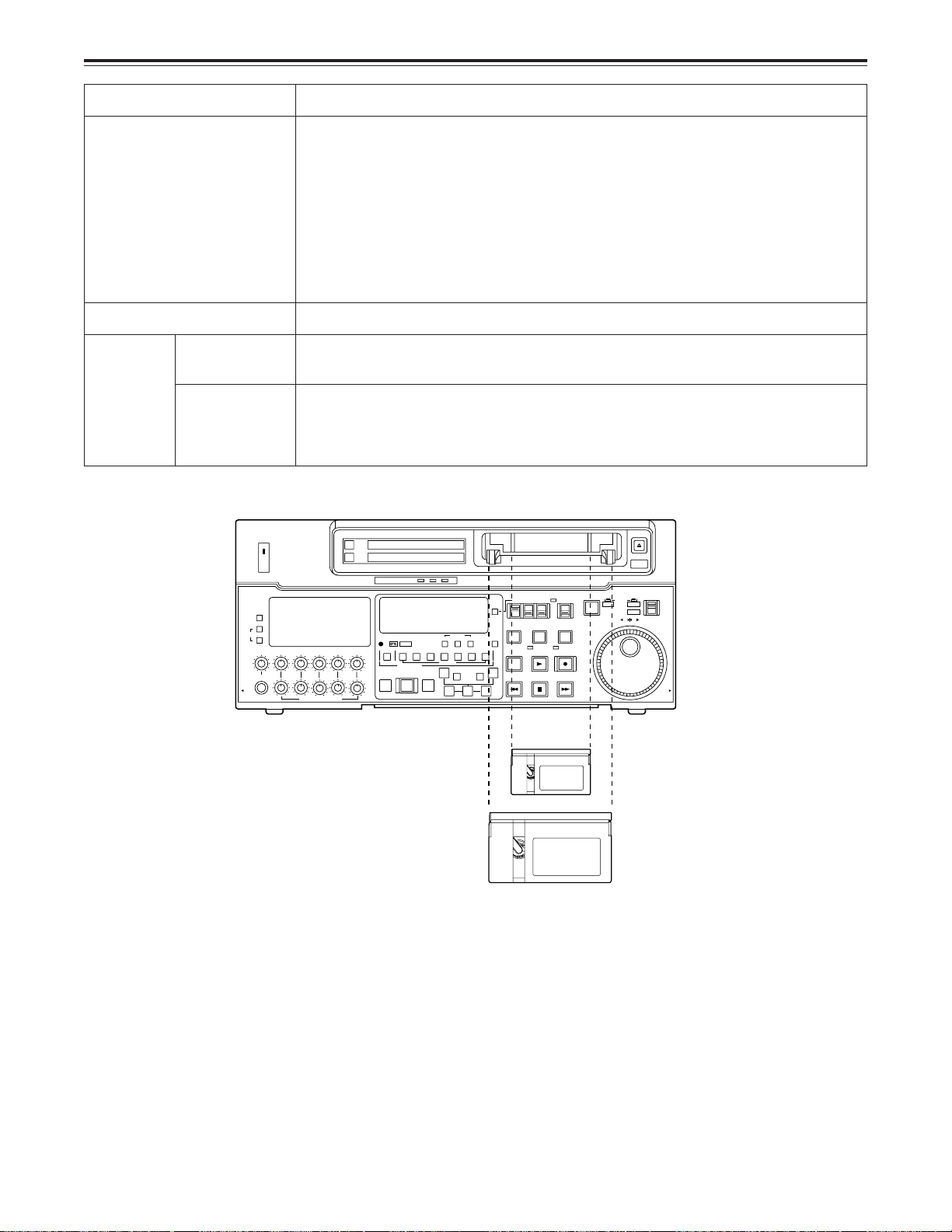
Tapes
Type Description
Consumer DV/DVCAM
S size cassette
These tapes are exclusively used with general consumer DV/DVCAM camera/
recorders.
They can be played back on the unit if a cassette adapter AJ-CS750P (available
as an optional accessory) is used. However, bear in mind that long-playing
consumer cassette tapes (80 minutes in the standard mode; 120 minutes in the
LP mode) cannot be used.
It is recommended that Panasonic’s DV tapes for general consumer DV
applications be used.
Bear in mind that inserting one of these cassette tapes without first installing the
cassette adapter will cause malfunctioning.
M size cassette
L cassette
DVCPRO
(50 Mbps)
For consumer
DV/DVCAM
use
Align the cassette with the centre of the insertion slot and push it in gently. The cassette tape
is loaded automatically.
ON
OFF
POWER
METER
FULL/FINE
L
MONITOR SELECT
R
LEVEL CH4 CUE
HEADPHONES
PULL
OPEN
Tapes with a maximum recording/playback time of 33 minutes. (AJ-P66MP)
Tapes with a maximum recording/playback time of 92 minutes. (AJ-5P92LP)
Standard playback cassette tapes for consumer DV/DVCAM use.
For playback, select DV or DVCAM as the setup menu item No. 014 (FORMAT
SEL) setting.
Use of Panasonic’s consumer-use DV tapes is recommended.
EJECT
AUTO OFF
PUSH
JOG
SHTL
SLOW
REV FWD
PULL
OPEN
CH1 CH2
CH3
PULL FOR VARIABLE
VIDEO Y PB PR
AUDIO ANALOG
REC
PREVIEW
REVIEW
PB
INPUT SELECT
CH CONDITION
W
ASSEM
CMPST
SDTI(V&A)
AES/EBU USER SET
SCH CF
DVCPRO
VIDEO CH1
MULTI CUE
AUTO EDIT
PREROLL
SDI
SDI
TC SET
SHIFT ADJ START RESET
CH2 CH3 CH4 CUE TC
4567321
INSERT
A
IN
–+
TRIM
SETIN OUT
TC MODE
CONTROL
TAPE
REMOTE
TC INT
TC/CTL
STAND BY
EDIT
8
A
OUT
REW
UB EXT EE
PLAYER
SERVO
PLAY
STOP
LOCAL
RECORDER
REC INHIBIT
REC
FF
M cassette
L cassette
<Note>
For AJ-5P92LP cassette tapes recorded using the DVCPRO (25 Mbps) mode, use a VTR supporting
DVCPRO (25 Mbps) 184 minute tapes.
<Precautions when playing back general consumer DV/DVCAM tapes>
• General consumer tapes recorded in the LP mode cannot be played back.
• When material recorded on a general consumer DV/DVCAM tape is to be edited, either use a
DVCPRO50 (50 Mbps) or DVCPRO (25 Mbps) tape or record the material on another VTR used for
broadcast applications.
• The maximum speed at which general consumer DV/DVCAM tapes can be advanced is 32 times the
normal tape speed.
• The maximum time for STILL TIMER when a general consumer DV/DVCAM tape is used is set to 10
seconds, and the total time during which such a tape may be left standing in the STILL mode is set to
1 minute.
• Cueing up a general consumer DV/DVCAM tape at the same position should be kept to the minimum
in order to protect the tape from damage.
• Noise may be generated on rare occasions during slow playback using a consumer-use DV/DVCAM
tape.
24 (E)
Page 25
Switching on the power/inserting the cassette
POWER
ON
OFF
L
LEVEL CH4 CUE
DVCPRO
AUDIO ANALOG
VIDEO Y PB PR
AES/EBU USER SET
CMPST
INPUT SELECT
SDI
CH CONDITION
SCH CF
SHIFT ADJ START RESET
STAND BY
UB EXT EE
TC INT
TC MODE
TAPE
LOCAL
REV FWD
PULL
OPEN
JOG
PUSH
EJECT
AUTO OFF
SHTL
SLOW
CONTROL
REMOTE
EDIT
REW
PLAY
SERVO
STOP
PLAYER
REC
REC INHIBIT
FF
RECORDER
TC/CTL
TC SET
INSERT
CH2
TRIM
SET OUTIN
CH3 CH4 CUE TC
AUTO EDIT
PREROLL
PREVIEW
REVIEW
REC
PB
PULL FOR VARIABLE
PULL
OPEN
HEADPHONES
CH1 CH2
R
METER
FULL/FINE
MONITOR SELECT
W
–+
SDI
SDTI(V&A)
ASMBL
VIDEO CH1
4567321
A
OUT
A
IN
MULTI CUE
CH3
8
SLOW MOTION
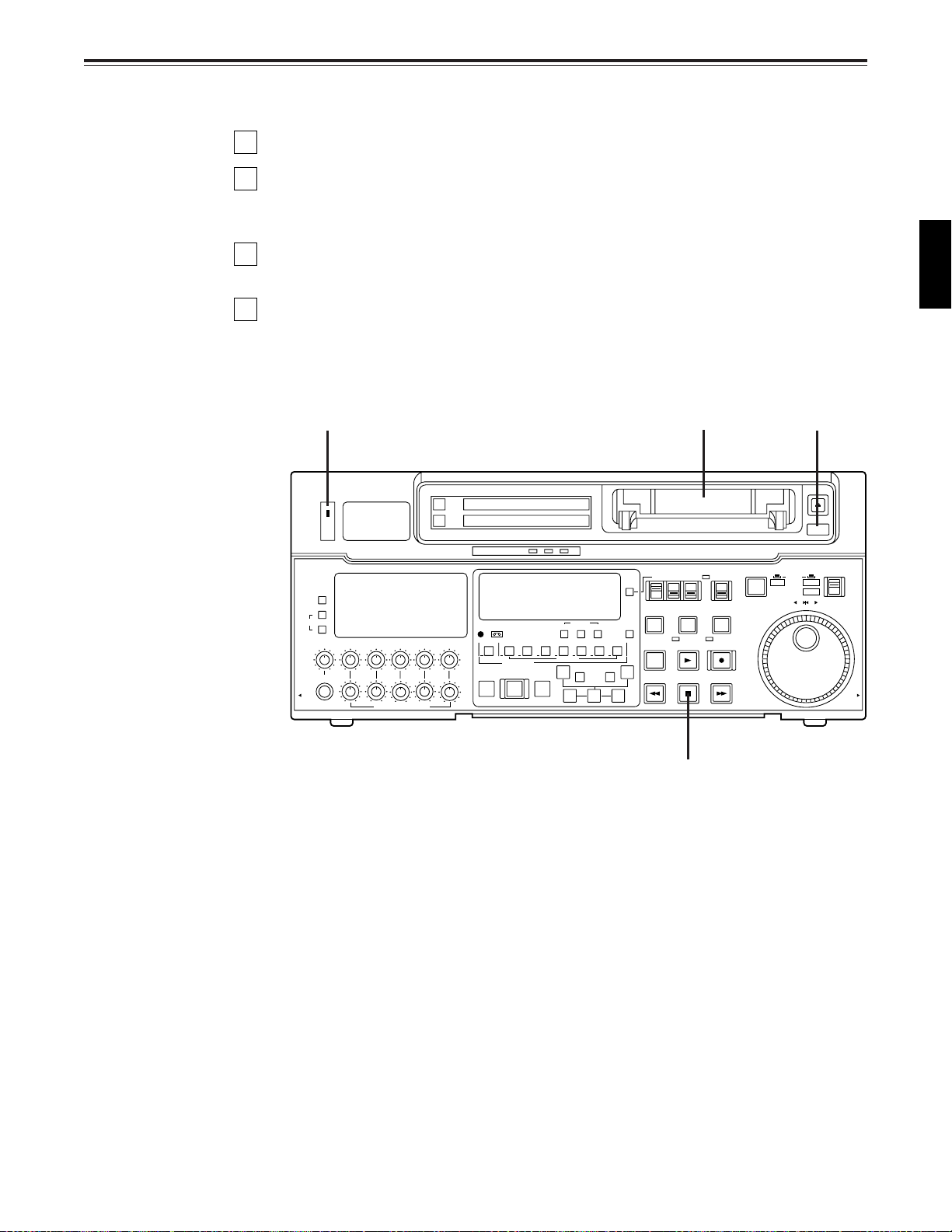
Before starting to operate the unit, check whether the equipment has been connected
properly.
1
Turn on the power.
2
Check that the AUTO OFF lamp is off.
When condensation has formed or some other trouble has occurred, the AUTO OFF
lamp lights, and all operations are disabled.
3
Insert the cassette tape.
Insert the tape at its proper position without force.
4
Check that the STOP lamp is on.
When the tape is inserted, the cylinder rotates automatically, the tape is loaded and the
unit goes into the stop mode. The EJECT lamp goes off.
1 3 2
ENGLISH
4
25 (E)
Page 26
STOP/STAND BY mode
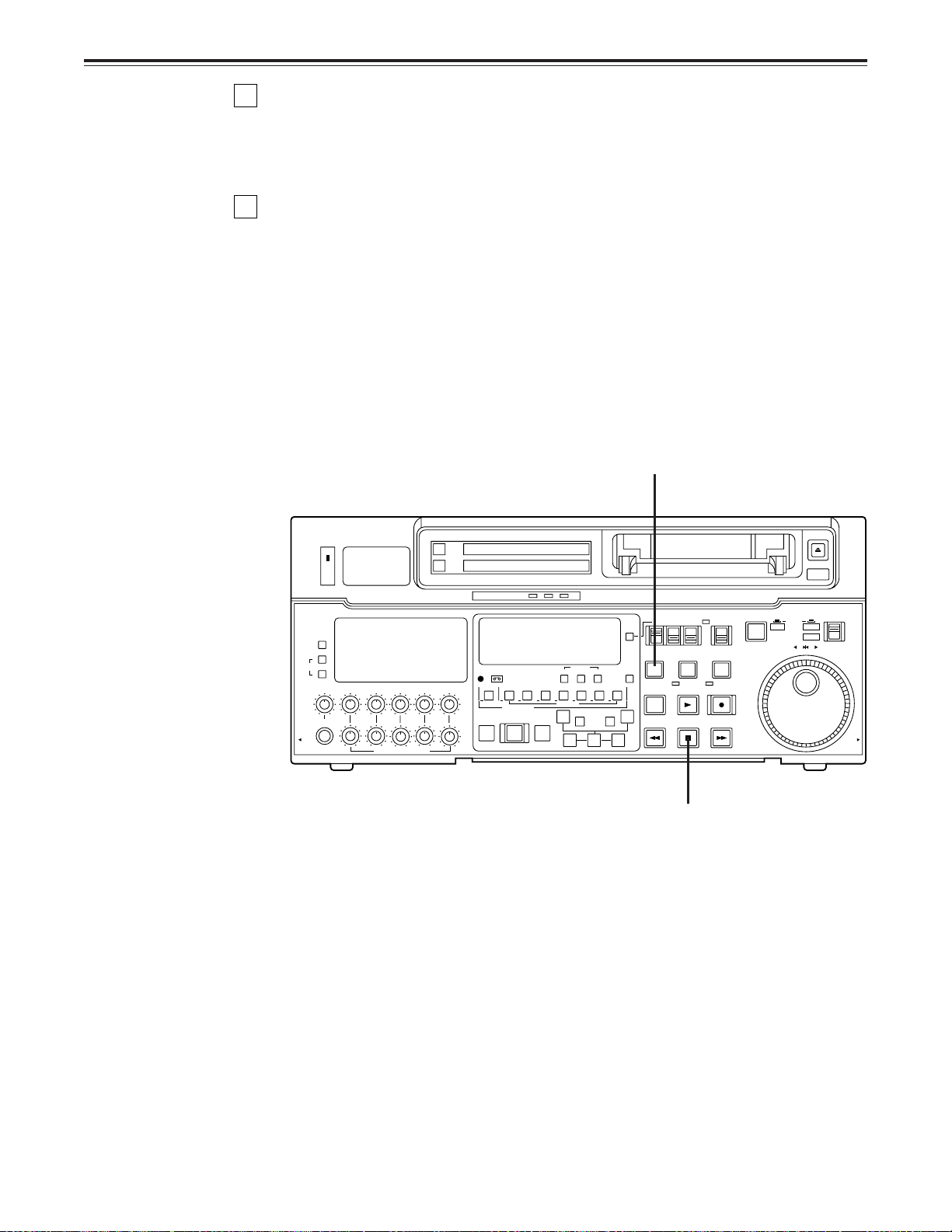
1
When the STOP button is pressed, the unit goes into the stop mode. The STOP lamp
lights and the tape stops travelling.
• In order to protect the tape, the unit goes into the standby OFF mode after the time set
by setup menu No. 400 (STILL TIMER) has elapsed. When the STOP, REW, FF or
PLAY button is pressed, the unit will go into the appropriate mode.
2
When the STAND BY button is pressed, the unit goes into the standby ON/OFF mode.
When the button’s lamp is lit, the unit is in the standby ON mode.
When the button is pressed during the stop mode, the unit goes into the standby OFF
mode and half-loading mode and the lamp goes off.
When the button is pressed during the standby OFF mode, the unit goes to the standby
ON mode.
Still Timer Setting
Page 74 indicates the settings for menu item 400-Still Timer set. Still Timer settings 4 and
below will best protect the tape.
2
ON
OFF
POWER
METER
FULL/FINE
L
MONITOR SELECT
R
LEVEL CH4 CUE
HEADPHONES
PULL
OPEN
CH1 CH2
CH3
PULL FOR VARIABLE
VIDEO Y PB PR
AUDIO ANALOG
W
REC
PREVIEW
REVIEW
PB
INPUT SELECT
CMPST
AES/EBU USER SET
CH CONDITION
DVCPRO
ASMBL
VIDEO CH1
MULTI CUE
AUTO EDIT
SDTI(V&A)
SHIFT ADJ START RESET
SCH CF
CH2
CH3 CH4 CUE TC
4567321
INSERT
PREROLL
SDI
SDI
TC SET
A
IN
–+
TRIM
SET OUTIN
EJECT
AUTO OFF
TC MODE
CONTROL
TAPE
PLAYER
SERVO
PLAY
STOP
REMOTE
LOCAL
RECORDER
REC INHIBIT
REC
FF
SLOW MOTION
TC INT
TC/CTL
UB EXT EE
STAND BY
EDIT
8
A
OUT
REW
PUSH
SHTL
JOG
SLOW
REV FWD
PULL
OPEN
1
26 (E)
Page 27

Recording
1
Set the accidental erasure prevention tab on the cassette tape to the “recording”
position and insert the tape.
2
Press the STOP button to place the unit in the stop mode.
3
Set the TAPE/EE switch to EE.
EE images now appear on the TV monitor.
4
Check that the REC INHIBIT lamp is off.
If this lamp is lit, set the REC INHIBIT switch to OFF.
5
Select the video and audio input signals and adjust their levels.
5-1 Selecting video/audio input signals
1 Connect the signals to be recorded.
2 Select the input signals using the INPUT SELECT switches on the front panel.
The input signals corresponding to the lit lamps have been selected.
5-2 Adjusting the video level
[When the analogue video input board (optional accessory) has been installed]
1 Normally, the VIDEO IN LEVEL control/switch %0 is left at the “PRESET”
setting (unity value).
2 To adjust the recording level, set the VIDEO IN LEVEL control/switch %0 to
“MANUAL” and use it to adjust the level to a setting between +3 dB and –3 dB.
ENGLISH
5-3 Adjusting the audio level
1 Adjust the audio input signal levels of the analogue audio CH1/CH2, CH3/CH4
signals and analogue cue signal. Keep the audio input/output level controls $5
pushed in (unity value).
The audio signals will be recorded at the proper level.
2 To adjust the recording level, pull out the controls $5 and adjust them. With the
CUE signal, adjust the control in such a way that –20 dB will not be exceeded.
6
Press the PLAY button while holding down the REC button. The REC and PLAY lamps
light, and recording commences.
7
To end the recording, press the STOP button.
Recording is ended, and the unit goes into the stop mode.
<Notes>
• Check that the SERVO lamp is lit during recording. If it flashes or if it is off, the images
played back will be disturbed.
• Only the analogue composite video input signals can be adjusted. (The digital video and
analogue component input signals cannot be adjusted.)
27 (E)
Page 28

Playback
1
Insert the cassette tape, and place the unit in the stop mode.
2
Press the PLAY button.
Regular playback is now commenced.
3
Adjust the audio playback level.
Pull out the audio level controls and turn them clockwise or counterclockwise to adjust
the levels. Normally, they are kept in the pushed-in state (unity value).
4
To end playback, press the STOP button.
The VTR now goes into the stop mode.
<Note>
Check that the SERVO lamp is lit during playback. If it flashes or if it is off, the images played
back will be disturbed.
28 (E)
Page 29

Jog/shuttle
Jog mode
1
Push the search dial to the “in” position.
Be sure that the JOG lamp lights.
2
Rotate the search dial.
The dial’s clickstops are cleared, and the tape is played back at the speed (–1× to +2×
normal speed*) corresponding to the speed at which the dial is turned. When the dial
rotation is stopped, a still picture appears. The playback picture is noise-free.
*The jog speed ranges from –1× to +1× with DV and DVCAM tapes.
Shuttle mode
3
To transfer from the jog mode to another mode, press the appropriate button.
1
Push the search dial to release it from the “in” position. The SHTL lamp lights, and the
unit goes into the shuttle mode.
• Immediately after the power has been turned on, rotate the search dial and set it to the
centre position.
2
Set the SHTL/SLOW switch to SHTL or SLOW.
3
Rotate the search dial.
When the SHTL/SLOW switch has been set to SHTL, the playback picture speed is
varied from 0 to ±32× normal speed depending on the position of the dial. The playback
picture speed can be switched to ±8.4×, ±16× and ±32× normal speed with setting
menu No. 101 (SHTL MAX).
The dial’s centre position is a clickstop where a still picture appears as the playback
image. When the SHTL/SLOW switch has been set to SLOW, the playback picture
speed is varied from –4.1 to +4.1× normal speed depending on the position of the dial.
The maximum speed can be selected using the setup menu No. 320 (VAR FWD MAX)
and No. 321 (VAR REV MAX). However, noise appears at speeds other than –1 to +2×
normal speed*.
The dial’s centre position is a clickstop where a still picture appears as the playback
image. The playback picture is noise-free.
*Noise will be generated outside the shuttle speed range of –1× to +1× with DV and
DVCAM tapes.
ENGLISH
4
To transfer from the shuttle mode to another mode, press the STOP button or other
button.
<Note>
When the unit leaves the factory, its operation is set up so that it will be transferred to the
shuttle or jog mode when the search dial is rotated. If it is inconvenient for operation to be
transferred to the variable-speed mode directly, it can also be transferred through the search
button.
Set setup menu No. 100 (SEARCH ENA) to KEY.
29 (E)
Page 30

Manual editing
1
2
3
4
5
Select the editing mode.
ASSEMBLE: For assemble editing.
INSERT: For insert editing.
Select the editing channel.
In the case of insert editing, press the channel button corresponding to the signals to be
edited, and check that its lamp is on.
Press the PLAY button.
Search for the position where the editing is to be commenced (IN point) while viewing
the TV monitor, and press the PLAY and EDIT buttons together at the IN point.
Press the STOP or PLAY button at the position where editing is to be completed (OUT
point) while viewing the TV monitor. The unit goes into the stop mode, and editing is
completed.
30 (E)
Page 31

Preroll
1
Press the PREROLL button.
The VTR now performs the preroll operation.
• When the edit IN point has been entered, the tape is rewound from the edit IN point for
the duration set by setup menu “000,” and the unit then goes into the stop mode.
• When the edit IN point has not been entered, the tape is rewound for the duration set
by setup menu “000” from the position where the button was pressed, and the unit
then goes into the stop mode.
<Notes>
• The time code or CTL signal must be continuously recorded between the edit IN point and
preroll point.
• When the IN point has not been entered, whether to enter the IN point and perform preroll
or to perform preroll without entering the IN point can be selected at setup menu No. 313
(AUTO ENTRY).
ENGLISH
31 (E)
Page 32

Automatic editing (Deck to Deck)
Editing refers to the job of using a prerecorded tape to produce a complete recording by
joining together separate cuts and deleting unnecessary parts.
The basic steps taken for editing are as follows.
1
Set the CONTROL switch to REMOTE on the player and to LOCAL on the recorder.
2
Select the editing mode.
3
Enter the edit points of the recorder and player.
4
Check and modify the edit points.
5
Check (Preview) before proceeding with the editing.
6
Proceed with the editing.
7
Check (Review) the recording that has resulted from the editing.
32 (E)
Page 33

Automatic editing
POWER
ON
OFF
L
LEVEL CH4 CUE
DVCPRO
AUDIO ANALOG
VIDEO Y PB PR
AES/EBU USER SET
CMPST
INPUT SELECT
SDI
CH CONDITION
SCH CF
SHIFT ADJ START RESET
STAND BY
UB EXT EE
TC INT
TC MODE
TAPE
LOCAL
REV FWD
PULL
OPEN
JOG
PUSH
EJECT
AUTO OFF
SHTL
SLOW
CONTROL
REMOTE
EDIT
REW
PLAY
SERVO
STOP
PLAYER
REC
REC INHIBIT
FF
RECORDER
TC/CTL
TC SET
INSERT
CH2
TRIM
SET OUTIN
CH3 CH4 CUE TC
AUTO EDIT
PREROLL
PREVIEW
REVIEW
REC
PB
PULL FOR VARIABLE
PULL
OPEN
HEADPHONES
CH1 CH2
R
METER
FULL/FINE
MONITOR SELECT
W
–+
SDI
SDTI(V&A)
ASMBL
VIDEO CH1
4567321
A
OUT
A
IN
MULTI CUE
CH3
8
SLOW MOTION
Set the time counter display to TC or CTL.
Set the POWER switch
to ON.
Select the video and audio input
signals using the INPUT SELECT
switches.
Set the CONTROL
switch to LOCAL.
Adjust the recording level.
Switch settings and adjustments
When the unit is used as the recorder:
ENGLISH
When the unit is used as the player:
Set the POWER switch to ON.
INPUT SELECT
ON
OFF
POWER
METER
FULL/FINE
L
MONITOR SELECT
R
LEVEL CH4 CUE
CH1 CH2
HEADPHONES
PULL
OPEN
Adjust the playback level.
PULL FOR VARIABLE
CH3
VIDEO Y PB PR
AUDIO ANALOG
CMPST
AES/EBU USER SET
CH CONDITION
W
ASMBL
VIDEO CH1
REC
PREVIEW
REVIEW
PB
Set the CONTROL
switch to REMOTE.
SDI
SDTI(V&A)
SDI
TC MODE
CONTROL
TAPE
PLAYER
SERVO
PLAY
STOP
REMOTE
LOCAL
RECORDER
REC INHIBIT
REC
FF
TC INT
TC/CTL
UB EXT EE
TC SET
SHIFT ADJ START RESET
SCH CF
DVCPRO
CH2
CH3 CH4 CUE TC
4567321
MULTI CUE
AUTO EDIT
INSERT
A
IN
PREROLL
–+
TRIM
SET OUTIN
Set the time counter display to TC or CTL.
STAND BY
EDIT
8
A
OUT
REW
SLOW MOTION
EJECT
AUTO OFF
PUSH
JOG
SHTL
SLOW
REV FWD
PULL
OPEN
33 (E)
Page 34

Automatic editing
Select the editing mode
1
Select the editing mode.
For assemble editing, press the ASSEMBLE button.
For insert editing, press the INSERT button.
ASSEMBLE: The assemble editing mode (in which cuts are joined together) is
INSERT: The insert editing mode (in which cuts are inserted) is established.
2
Select the editing channel.
With assemble editing, the ASSEMBLE lamp lights.
With insert editing, press the button of the channel whose signals are to be edited and
light its lamp.
3
Select the VTR to be operated (this setting is performed when editing with 2 VTRs).
Press the PLAYER or RECORDER button to select the VTR.
PLAYER: Press this button to operate the player VTR and enter the edit points.
RECORDER: Press this button to operate the recorder VTR (this unit) and enter the
established.
edit points.
1, 2
ON
OFF
POWER
METER
FULL/FINE
L
MONITOR SELECT
R
LEVEL CH4 CUE
HEADPHONES
PULL
OPEN
CH1 CH2
CH3
PULL FOR VARIABLE
VIDEO Y PB PR
AUDIO ANALOG
W
REC
PREVIEW
REVIEW
PB
INPUT SELECT
CMPST
AES/EBU USER SET
CH CONDITION
DVCPRO
ASMBL
VIDEO CH1
MULTI CUE
AUTO EDIT
SDTI(V&A)
SHIFT ADJ START RESET
SCH CF
CH2
CH3 CH4 CUE TC
4567321
INSERT
PREROLL
SDI
SDI
TC SET
A
IN
–+
TRIM
SET OUTIN
EJECT
AUTO OFF
TC MODE
CONTROL
TAPE
PLAYER
SERVO
PLAY
STOP
REMOTE
LOCAL
RECORDER
REC INHIBIT
REC
FF
SLOW MOTION
TC INT
TC/CTL
UB EXT EE
STAND BY
EDIT
8
A
OUT
REW
PUSH
SHTL
JOG
SLOW
REV FWD
PULL
OPEN
3
34 (E)
Page 35

Automatic editing
POWER
ON
OFF
L
LEVEL CH4 CUE
DVCPRO
AUDIO ANALOG
VIDEO Y PB PR
AES/EBU USER SET
CMPST
INPUT SELECT
SDI
CH CONDITION
SCH CF
SHIFT ADJ START RESET
STAND BY
UB EXT EE
TC INT
TC MODE
TAPE
LOCAL
REV FWD
PULL
OPEN
JOG
PUSH
EJECT
AUTO OFF
SHTL
SLOW
CONTROL
REMOTE
EDIT
REW
PLAY
SERVO
STOP
PLAYER
REC
REC INHIBIT
FF
RECORDER
TC/CTL
TC SET
INSERT
CH2
TRIM
SET OUTIN
CH3 CH4 CUE TC
AUTO EDIT
PREROLL
PREVIEW
REVIEW
REC
PB
PULL FOR VARIABLE
PULL
OPEN
HEADPHONES
CH1 CH2
R
METER
FULL/FINE
MONITOR SELECT
W
–+
SDI
SDTI(V&A)
ASMBL
VIDEO CH1
4567321
A
OUT
A
IN
MULTI CUE
CH3
8
SLOW MOTION
Entering the edit points
1
Search for the edit IN point by performing the jog or shuttle operation.
Establish the still picture mode at the desired position.
Refer to page 29 for details on the jog/shuttle operations.
2
Press the SET button while holding down the IN button.
The edit IN point is now entered.
The edit IN point value now appears on the display.
3
Search for the edit OUT point by performing the jog or shuttle operation.
Establish the still picture mode at the desired position.
Refer to page 29 for details on the jog/shuttle operations.
4
Press the SET button while holding down the OUT button.
The edit OUT point is now entered.
The edit OUT point value now appears on the display.
ENGLISH
1, 32, 4
Match frame processing function
When using two VTRs for editing, a total of four edit points—namely, the player’ s IN and OUT
points and the recorder’s IN and OUT points—need to be entered. However, since the last
edit point is calculated automatically, only three of these edit points must be entered.
Negative duration function
This function is used by combining setup menu No. 301 (IN/OUT DEL) and No. 302 (NEGA
FLASH).
35 (E)
Page 36

Automatic editing
Checking the edit points
1
Press the IN (or OUT) button to check the edit point.
The value of the entered edit point appears on the display.
2
Press the PREROLL button while holding down the IN (or OUT) button to check the
image at the edit point.
The tape is cued at the edit IN (or OUT) point, and the still picture mode at that point is
displayed.
• The EE mode is established if the TAPE/EE switch has been set to the “EE” position
when “STOP” has been selected for the setup menu No. 315 (AFTER CUE-UP).
3
Continue to hold the IN and OUT buttons down together, and check the edit section
(duration time).
The duration time appears on the display.
Calculating the duration
• When both edit points have been set, the duration between the two edit points.
• When only one edit point has been set, the duration between the set data and the current
tape address.
• When neither edit point has been set, the duration of the previously edited interval.
ON
OFF
POWER
METER
FULL/FINE
L
MONITOR SELECT
R
LEVEL CH4 CUE
HEADPHONES
PULL
OPEN
CH1 CH2
CH3
PULL FOR VARIABLE
VIDEO Y PB PR
AUDIO ANALOG
W
REC
PREVIEW
REVIEW
PB
INPUT SELECT
CMPST
AES/EBU USER SET
CH CONDITION
DVCPRO
ASMBL
VIDEO CH1
MULTI CUE
AUTO EDIT
SDI
SDTI(V&A)
SDI
TC SET
SHIFT ADJ START RESET
SCH CF
CH2
CH3 CH4 CUE TC
4567321
INSERT
A
IN
PREROLL
–+
TRIM
SET OUTIN
2 1, 3
EJECT
AUTO OFF
TC MODE
CONTROL
TAPE
PLAYER
SERVO
PLAY
STOP
REMOTE
LOCAL
RECORDER
REC INHIBIT
REC
FF
SLOW MOTION
TC INT
TC/CTL
UB EXT EE
STAND BY
EDIT
8
A
OUT
REW
PUSH
SHTL
JOG
SLOW
REV FWD
PULL
OPEN
36 (E)
Page 37

Automatic editing
Modifying the edit points
1
Re-entering the edit points
Search for the new edit point by performing the jog or shuttle operation, and press the
IN (or OUT) and SET buttons together to re-enter the edit point.
2
Modifying the edit point in frame units (trim function)
Press the TRIM button while holding down the IN (or OUT) button.
The edit point is put ahead by 1 frame each time the + button is pressed.
The edit point is put back by 1 frame each time the – button is pressed.
3
Resetting the edit points
3-1 Resetting both the edit IN and OUT points
• Press the RESET button.
3-2 Resetting either the edit IN or OUT point
• Press the RESET button while holding down the IN (or OUT) button.
<Notes>
• Edit points can be reset only in the CTL mode.
• An edit OUT point can be reset even while editing is in progress.
• The IN and OUT points are automatically reset during the eject mode.
3-1, 3-2
ON
OFF
POWER
METER
FULL/FINE
L
MONITOR SELECT
R
LEVEL CH4 CUE
HEADPHONES
PULL
OPEN
CH1 CH2
CH3
PULL FOR VARIABLE
VIDEO Y PB PR
AUDIO ANALOG
W
REC
PREVIEW
REVIEW
PB
INPUT SELECT
CMPST
AES/EBU USER SET
CH CONDITION
DVCPRO
ASMBL
VIDEO CH1
MULTI CUE
AUTO EDIT
SDTI(V&A)
SHIFT ADJ START RESET
SCH CF
CH2
CH3 CH4 CUE TC
4567321
INSERT
PREROLL
SDI
SDI
TC SET
A
IN
–+
TRIM
SET OUTIN
TC MODE
TAPE
TC INT
TC/CTL
UB EXT EE
STAND BY
PLAYER
RECORDER
SERVO
EDIT
REW
PLAY
STOP
8
A
OUT
CONTROL
REMOTE
LOCAL
REC INHIBIT
REC
FF
SLOW MOTION
1
EJECT
AUTO OFF
PUSH
SHTL
JOG
SLOW
REV FWD
PULL
OPEN
ENGLISH
37 (E)
2
Page 38

Automatic editing
Preview
1
After the edit points have been entered, press the PREVIEW button.
Normal preview is now performed.
<Notes>
• If the edit IN point has not been entered, the position where the PREVIEW button was
pressed will be entered at the edit IN point.
• To stop the preview at any time, press the STOP button.
• If the PREVIEW button is pressed again while preview is in progress after the IN point,
preview will start again from the beginning.
• When the edit OUT point is reached, the unit automatically goes into the stop mode.
ON
OFF
POWER
METER
FULL/FINE
L
MONITOR SELECT
R
LEVEL CH4 CUE
HEADPHONES
PULL
OPEN
CH1 CH2
CH3
PULL FOR VARIABLE
VIDEO Y PB PR
AUDIO ANALOG
W
REC
PREVIEW
REVIEW
PB
1
INPUT SELECT
CMPST
AES/EBU USER SET
CH CONDITION
DVCPRO
ASMBL
VIDEO CH1
MULTI CUE
AUTO EDIT
SDTI(V&A)
SHIFT ADJ START RESET
SCH CF
CH2
CH3 CH4 CUE TC
4567321
INSERT
PREROLL
SDI
SDI
TC SET
A
IN
–+
TRIM
SET OUTIN
EJECT
AUTO OFF
TC MODE
CONTROL
TAPE
PLAYER
SERVO
PLAY
STOP
REMOTE
LOCAL
RECORDER
REC INHIBIT
REC
FF
SLOW MOTION
TC INT
TC/CTL
UB EXT EE
STAND BY
EDIT
8
A
OUT
REW
PUSH
SHTL
JOG
SLOW
REV FWD
PULL
OPEN
38 (E)
Page 39

Automatic editing
Executing automatic editing
1
Press the AUTO EDIT button.
Automatic editing is now performed.
• To stop the editing at any time, press the STOP button.
• When the edit OUT point is reached, the unit goes into the stop mode after
postrolling*.
* The postroll time can be set using setup menu No. 325 (POSTROLL TM).
Postroll
With assemble editing, editing continues for approx. 2 seconds even after the edit OUT point
has been passed, the tape is rewound to the OUT point, and the unit goes into the stop
mode.
With insert editing, the unit goes into the play mode after the edit OUT point has been
passed, the tape is rewound to the OUT point, and the unit goes into the stop mode.
Retry function
If the AUTO EDIT button is pressed again after the STOP button has been pressed to stop
the editing, editing will start again from the beginning.
Auto tag editing
If the AUTO EDIT button is pressed when the next edit point has not yet been entered upon
completion of editing, the previous edit OUT point will be entered as the IN point, and editing
is performed accordingly.
To release the auto tag mode, press one of the tape transport buttons (PLAY, etc.).
<Note>
The entered points are automatically cleared after editing is executed. However, the previous
editing points can be recalled by pressing the TRIM+ (or TRIM–) and SET buttons together.
ON
OFF
POWER
METER
FULL/FINE
L
MONITOR SELECT
R
LEVEL CH4 CUE
HEADPHONES
PULL
OPEN
CH1 CH2
CH3
PULL FOR VARIABLE
VIDEO Y PB PR
AUDIO ANALOG
W
REC
PREVIEW
REVIEW
PB
INPUT SELECT
CMPST
AES/EBU USER SET
CH CONDITION
DVCPRO
ASMBL
VIDEO CH1
MULTI CUE
AUTO EDIT
SDTI(V&A)
SHIFT ADJ START RESET
SCH CF
CH2
CH3 CH4 CUE TC
4567321
INSERT
PREROLL
SDI
SDI
TC SET
A
IN
–+
TRIM
SET OUTIN
TC MODE
CONTROL
TAPE
PLAYER
SERVO
PLAY
STOP
REMOTE
LOCAL
RECORDER
REC INHIBIT
REC
FF
SLOW MOTION
TC INT
TC/CTL
UB EXT EE
STAND BY
EDIT
8
A
OUT
REW
EJECT
AUTO OFF
PUSH
SHTL
JOG
SLOW
REV FWD
PULL
OPEN
ENGLISH
39 (E)
1
Page 40

Automatic editing
Review
1
Upon completion of the editing, press the REVIEW button.
The review is started in the recorder.
• To stop the review at any time, press the STOP button.
• When the edit OUT point is reached, the unit goes into the stop mode after
postrolling*.
* The postroll time can be set using setup menu No. 325 (POSTROLL TM).
ON
OFF
POWER
METER
FULL/FINE
L
MONITOR SELECT
R
LEVEL CH4 CUE
HEADPHONES
PULL
OPEN
CH1 CH2
CH3
PULL FOR VARIABLE
VIDEO Y PB PR
AUDIO ANALOG
W
REC
PREVIEW
REVIEW
PB
1
INPUT SELECT
CMPST
AES/EBU USER SET
CH CONDITION
DVCPRO
ASMBL
VIDEO CH1
MULTI CUE
AUTO EDIT
SDTI(V&A)
SHIFT ADJ START RESET
SCH CF
CH2
CH3 CH4 CUE TC
4567321
INSERT
PREROLL
SDI
SDI
TC SET
A
IN
–+
TRIM
SET OUTIN
EJECT
AUTO OFF
TC MODE
CONTROL
TAPE
PLAYER
SERVO
PLAY
STOP
REMOTE
LOCAL
RECORDER
REC INHIBIT
REC
FF
SLOW MOTION
TC INT
TC/CTL
UB EXT EE
STAND BY
EDIT
8
A
OUT
REW
PUSH
SHTL
JOG
SLOW
REV FWD
PULL
OPEN
40 (E)
Page 41

Audio split editing
The video edit points and audio edit points can be entered separately, and they can be offset
from each other and edited.
The audio edit points cannot be entered when the assemble editing mode has been
selected. After the edit points have been entered, follow the same operating procedure as
that for insert editing.
■ Entering the edit points
Video IN point: Press the SET button while holding down the IN button.
Video OUT point: Press the SET button while holding down the OUT button.
Audio IN point: Press the SET button while holding down the A-IN button.
Audio OUT point: Press the SET button while holding down the A-OUT button.
■ Deleting the edit points
Video IN point: Press the RESET button while holding down the IN button.
Video OUT point: Press the RESET button while holding down the OUT button.
Audio IN point: Press the RESET button while holding down the A-IN button.
Audio OUT point: Press the RESET button while holding down the A-OUT button.
■ Modifying the edit points
Video IN point: Press the TRIM+ or TRIM– button while holding down the IN button.
Video OUT point: Press the TRIM+ or TRIM– button while holding down the OUT button.
Audio IN point: Press the TRIM+ or TRIM– button while holding down the A-IN button.
Audio OUT point: Press the TRIM+ or TRIM– button while holding down the A-OUT button.
ENGLISH
■ Indicating audio split editing
When the audio edit points are entered, “ ” appears superimposed on the front panel and
TV monitor to denote audio split editing.
TCR 00:00:00:00
AUTO EDIT
This denotes audio split editing.
ON
OFF
POWER
METER
FULL/FINE
L
MONITOR SELECT
R
LEVEL CH4 CUE
HEADPHONES
PULL
OPEN
CH1 CH2
CH3
PULL FOR VARIABLE
VIDEO Y PB PR
AUDIO ANALOG
W
REC
PREVIEW
REVIEW
PB
INPUT SELECT
CMPST
AES/EBU USER SET
CH CONDITION
DVCPRO
ASMBL
VIDEO CH1
MULTI CUE
AUTO EDIT
SDTI(V&A)
SHIFT ADJ START RESET
SCH CF
CH2
CH3 CH4 CUE TC
4567321
INSERT
PREROLL
SDI
SDI
TC SET
A
IN
–+
TRIM
SET OUTIN
TC MODE
CONTROL
TAPE
PLAYER
SERVO
PLAY
STOP
REMOTE
LOCAL
RECORDER
REC INHIBIT
REC
FF
SLOW MOTION
TC INT
TC/CTL
UB EXT EE
STAND BY
EDIT
8
A
OUT
REW
EJECT
AUTO OFF
PUSH
SHTL
JOG
SLOW
REV FWD
PULL
OPEN
41 (E)
A-IN
button
A-OUT
button
Page 42

Audio split editing
■ Displaying the audio split edit points
The edit points are displayed on the front panel as shown below. (The figure shows an audio
IN point.)
Operations
Video IN point: Press the IN button.
Video OUT point: Press the OUT button.
Audio IN point: Press the A-IN button.
Audio OUT point: Press the A-OUT button.
<Note>
If the editing mode is switched to assemble editing after audio edit points have entered,
these points will be deleted.
■ Cueing up the tape to the edit points
Cue-up to video IN point: Press the PREROLL button while holding down the IN button.
Cue-up to video OUT point: Press the PREROLL button while holding down the OUT
Cue-up to audio IN point: Press the PREROLL button while holding down the A-IN
Cue-up to audio OUT point: Press the PREROLL button while holding down the A-OUT
AIN 00:00:04:07
IN, OUT, AIN (audio IN point), AOUT (audio OUT point)
button.
button.
button.
■ Duration display
The duration can be displayed on the front panel only.
Duration from video IN point to OUT point: Press the IN and OUT buttons simultaneously.
Duration from audio IN point to OUT point: Press the A-IN and A-OUT buttons simulta-
neously.
Match frame processing mechanism
When two VTRs are used for audio split editing operations, there will be a total of eight edit
points: two pairs of video IN and OUT points, one for the player and the other for the
recorder, and two pairs of audio IN and OUT points, one for the player and the other for the
recorder. Since the remaining three points are automatically calculated when five of these
eight edit points are entered, up to five edit points can be entered.
■ When a VTR without a split editing function is to be used as the
player
When a VTR which does not have the ability to set the video and audio edit points separately
is used as the player, split editing can still be performed by setting the audio In and OUT
points using the recorder and setting the data of three points as the video edit points.
<Note>
If, during audio split editing, only the video OUT point (or audio OUT point) is entered and
automatic editing is executed without the audio OUT point (or video OUT point) having been
entered, editing will continue until the audio OUT point (or video OUT point) is entered or the
STOP button is pressed to suspend operation.
42 (E)
Page 43

Voice-over facility (internal)
Operating procedure 1
MIC
AMP
Microphone
* Connect to the channel whose
sound is to be recorded.
1
Select INT_VO as the setup menu No. 317 (AUD MEM MODE) setting.
2
Select the same setting for the channel (any channel from CH1 to CH4) on which the
sound is to be recorded and for the setup menu No. 318 (AUD MEM CH) channel.
3
Insert the cassette tape for which the voice-over editing is to be performed.
4
Press the insert button for the channel (channel selected in step 2) on which the sound
is to be recorded and ensure that its lamp lights.
5
Press the PLAY button.
6
Search the position (IN point) where voice-over editing is to start while watching the TV
monitor.
7
Press the IN and SET buttons simultaneously at the IN point.
ANALOGUE
AUDIO
IN*
VIDEO
OUT
TV monitor
AJ-D960
ENGLISH
8
Input the audio signals to be recorded to the channel which was selected in step 2.
9
Search the position (OUT point) where voice-over editing is to end while watching the
TV monitor.
10
Press the OUT and SET buttons simultaneously at the OUT point. The audio signals to
be recorded are stored in the memory.
11
Press the STOP button.
12
Press the AUTO EDIT button to proceed with editing. The audio signals stored in the
memory are recorded from the memory onto the cassette tape.
<Note>
The audio signals can be previewed prior to editing by pressing the PREVIEW button while
the SET button is held down before the AUTO EDIT button is pressed.
43 (E)
Page 44

Voice-over facility (internal)
Operating procedure 2
1
Select INT_VO as the setup menu No. 317 (AUD MEM MODE) setting.
2
Select the same setting for the channel (any channel from CH1 to CH4) on which the
sound is to be recorded and for the setup menu No. 318 (AUD MEM CH) channel.
3
Insert the cassette tape for which the voice-over editing is to be performed.
4
Press the insert button for the channel (channel selected in step 2) on which the sound
is to be recorded and ensure that its lamp lights.
5
Enter the IN and OUT points of the positions where voice-over editing is to be
performed.
6
Press the PREVIEW button.
7
While watching the TV monitor, input the audio signals to be recorded between the IN
point and OUT point into the channel which was selected in step 2. The audio signals to
be recorded are stored in the memory.
8
Press the AUTO EDIT button to proceed with editing. The audio signals stored in the
memory are recorded from the memory onto the cassette tape.
<Note>
The audio signals can be previewed prior to editing by pressing the PREVIEW button
while the SET button is held down before the AUTO EDIT button is pressed.
T R 00:00:00:00
m STOP
“m” indicates the edit mode in which
the internal memory is used.
<Notes>
Memory capacity
• Up to 20 seconds of sound can be stored in the unit’s internal memory. It should be borne in
mind that even if an attempt is made to store more than 20 seconds of sound in the
memory, all the audio signals in excess of the memory’s 20-second capacity will fail to be
stored.
• When INT_VO or INT_X, which is performed using the internal memory in the setup menu
No. 317 (AUD MEM MODE) setting, “m” appears on the front panel and is superimposed
onto the TV monitor display to indicate that the editing mode using the internal memory is
now being used.
44 (E)
Page 45

MIC
AMP
ANALOGUE
AUDIO IN*
VIDEO
OUT
RECORDER
AJ-D960
AG-A850
REMOTE
IN/OUT
CONTROLLER
Ref.
Microphone
TV monitor
* Connect to the channel (any channel
from CH1 to CH4) on which the sound
is to be recorded.
Voice-over facility (internal)
For operation with an editing controller (AG-A850)
ENGLISH
1
Select INT_VO as the setup menu No. 317 (AUD MEM MODE) setting.
2
Select the same setting for the channel (any channel from CH1 to CH4) on which the
sound is to be recorded and for the setup menu No. 318 (AUD MEM CH) channel.
3
Insert the cassette tape for which the voice-over editing is to be performed into the
VTR.
4
Set the CONTROL switch on the VTR to the REMOTE position.
5
Set the controller’s SOURCE selector to AUX1.
6
Press the insert button for the channel (channel selected in step 2) on which the sound
is to be recorded.
7
Enter the IN and OUT points of the positions where voice-over editing is to be
performed.
8
9
10
Press the PREVIEW button.
While watching the TV monitor, input the audio signals to be recorded between the IN
point and OUT point into the channel that was selected in step 6. The audio signals to
be recorded are stored in memory.
Press the AUTO EDIT button to proceed with editing. The audio signals stored in the
memory are recorded from the memory onto the cassette tape.
<Note>
For further details on the AG-A850, refer to the operating instructions of the AG-A850.
45 (E)
Page 46

Audio cross channel editing (internal)
Example: To record cross-faded audio signals onto CH2
■ Connections
Ref
REMOTE
IN/OUT
PLAYER
AJ-D960
CH1
PLAYER RECORDER
INPUT
AUDIO
OUT
IN OUT
A
INPUT
B
Event 1
EDITING
CONTROLLER
AG-A850
REMOTE
AUDIO
CHI1 IN
AUDIO
CHI2 IN
IN/OUT
CHI1 OUT
AJ-D960
MIXER
CH1
OUT
MIXER
+
CH2
OUT
MIXER RECORDER
AUDIO
Fig. 1
CH2
IN OUT
Up to 20 sec.
CH1 insert start
CH1
Event 2
Fig. 2
CH2
Cross fading by operating the mixer
1
Select INT_X as the setup menu No. 317 (AUD MEM MODE) setting.
2
Select CH2 as the setup menu No. 318 (AUD MEM CH) setting.
3
Select the audio CH1 and CH2 in the insert editing.
<Note>
Select the video as well if the video signals are also going to be edited.
46 (E)
Page 47

Audio cross channel editing (internal)
4
Enter the edit points of the first event on the player’s tape.
5
Enter the edit points of the first event on the recorder’s tape.
6
Operate the mixer in such a way that the player’s audio output signals are output from
the mixer’s CH1 OUT and CH2 OUT connectors. (The same audio signals will be
delivered through CH1 and CH2 of the mixer.)
7
Press the AUTO EDIT button. The first event is now recorded on the recorder’s tape.
(See Fig. 1.)
The last 20 seconds (which is the capacity of the memory) of the audio signals before
the OUT point are now saved in the memory .
8
Release the insert button for CH1 so that only the insert button for CH2 is engaged.
<Note>
Select the video as well if the video signals are also going to be edited.
9
Enter the edit point of the next event on the player’s tape.
10
Enter the edit point of the next event on the recorder’s tape.
<Note>
The IN point must be set up to 20 seconds (more than the cross fading duration) before
the previous edit OUT point.
ENGLISH
11
Operate the mixer in such a way that the player’s audio output signals are output from
the mixer’s CH1 OUT connectors and that the recorder’s (this unit) CH1 OUT audio
signals are output from the mixer’s CH2 OUT connectors. [The recorder’s (this unit)
CH1 OUT signals are the audio signals supplied from the internal memory.]
12
Press the AUTO EDIT button.
13
Operate the mixer starting at the IN point, and change the mixer’s CH2 OUT signals
gradually from the recorder’s CH1 OUT audio signals into the player’s audio output
signals for the mixer’s CH2 OUT connectors. (Cross fading)
14
Press the CH1 insert button after the mixer’s CH2 output signals have been changed
into the player’s audio output signals. The STOP mode is established at the OUT point,
and the last 20 seconds (which is the capacity of the memory) of the audio signals
before the OUT point are now saved in the memory. (See Fig. 2.)
15
To continue editing, repeat steps 8 to 14.
Audio cross channel editing is possible only between CH1 and CH2 or between CH3 and
CH4.
<Notes>
Before attempting to perform voice-over editing or audio cross channel editing using the
audio memory unit (AJ-YA752, option), proceed with the following settings for the unit
(AJ-D960).
1. Select either AMU_X or AMU_VO as the setup menu No. 317 (AUD MEM MODE)
setting.
2. For audio cross channel editing, set the channel on which the signals are to be
recorded on setup menu No. 318 (AUD MEM CH).
3. Proceed with operation, using the AJ-YA752 operating instructions as a reference.
47 (E)
Page 48

¤
S R C 0 1 E N T 2 3 R 9 0
C U E 0 1 0 0
:
0 0
:
0 0
:
0 0
Description of display
MULTI CUE mode display
15 1634567891011121314 17181920
q Display mode
selection mark
w Search point e Entry point
T C R 0 0
:
0 0
:
0 0
:
0 0
15 16
R J O G S T I L L R 9 0
1234567891011121314 17181920
Time display
Operating mode display
r Search point or entry point time (remains
blank when nothing has been entered)
Remaining tape amount
or freeze display
Multi cue
■ Select the MULTI CUE mode using setup menu No. 130 (MULTI CUE).
■ The edit channel selector buttons (ASMBL, VIDEO, CH1/2/3/4, CUE, TC) can be used as
the CUE 1
through CUE 8 buttons.
↑↑
AB
CUEAB A: Denotes the page (pages 0 through 9).
B: Denotes the cue point (points 1 through 8).
■ A total of 80 cue points can be entered on up to 10 pages.
Using setup menu No. 131 (PAGE MODE), either of the following operation modes can be
selected for entering the cue points:
• Mode for performing operation on the selected page on which 8 cue points can be
entered.
• Mode for automatically moving entry forward onto the next page when the page on which
cue points are being entered has been filled, and continuing the entry onto successive
pages, thereby enabling a total of 80 cue points to be entered on up to 10 pages
Furthermore, using setup menu No. 132 (ROTA MODE), either of the following operation
modes can be selected when all the cue points have been entered.
• Mode in which the entry operation is not performed
• Mode in which the entry operation is performed (the first cue point is entered in CUE 1
on the existing page when “MANU” has been selected as the setup menu No. 131 (PAGE
MODE) setting or it is entered in CUE01 on page 0 when “AUTO” has been selected)
The following functions are provided when MULTI CUE has been selected:
• Editing is disabled in the MULTI CUE mode.
• The editing channel selector buttons (ASMBL, VIDEO, CH1/2/3/4, CUE, TC) are automatically released when the unit has been transferred to the MULTI CUE mode in the
editing mode selection status.
• Deck-to-deck operations cannot be used in the MULTI CUE mode.
• The mode display will not appear on the front panel counter display in the MULTI CUE
mode.
Further, messages and other information are forcibly displayed when AUTO-OFF has
occurred.
48 (E)
Page 49

Multi cue
q Display mode selection mark
This mark indicates whether the current cue point LED display (and time data displayed by
the operation) is to indicate the search point or entry point. (The display is switched using
the START button on the front panel as shown in the figure below.)
¤
S R C 0 1 E N T 2 3 R 9 0
S R C 0 1
¤
E N T 2 3 R 9 0
START
w Search point
This displays the currently selected search point. (“SCR01” denotes CUE1 on page 0.)
e Entry point
This displays the point to be entered when the SET button is pressed next. (“ENT23”
denotes CUE3 on page 2.)
r Search point and entry point display
This displays the search point or entry point time when the CUE button and SET buttons
have been pressed. (The display remains blank when there is no time data.)
Page operations
Pages can be scrolled up or down by simultaneously pressing the front panel ADJ button and
TRIM +/– button.
• Page up scrolling is set as follows using setup menu No. 132 (ROTE MODE).
When OFF is set: Scrolling is not possible from page 9 to page 0.
When ON is set: Scrolling is possible from page 9 to page 0.
• Page down scrolling from page 0 to page 9 is not possible.
ENGLISH
Search point or entry point operations
Each time the START button is pressed, the search point display mode and entry point
display mode are switched alternately.
Perform the operations for the search point or entry point in the respective mode.
• When the power is on, both the search and entry pointers point to CUE01 (page 0/cue point
1), and the entry point display mode serves as the display mode.
• When the setup menu No. 131 (PAGE MODE) or No. 132 (ROTA MODE) setting has been
changed, both the search and entry pointers will point to CUE01 (page 0/cue point 1).
Search point operations
Search pointer operations can be performed when the display below has appeared on the
operation panel. The selected search point LED flashes, and its number is indicated on the
panel.
Example of panel
display
Example of LED
display
¤
S R C 0 1 E N T 2 3 R 9 0
ASMBL VIDEO
Flashes Lights
CH2 CH3 CH4 CUE TC
CH1
45678123
(point already
entered)
Off
(point not
entered)
49 (E)
Page 50

Multi cue
• The search pointer position is changed directly by pressing one of the buttons from CUE 1
to CUE 8 (ASMBL-TC) on the same page.
• When the page has been changed by simultaneously pressing the ADJ button and TRIM
+/– button, the following steps are performed depending on the setup menu No. 131 (PAGE
MODE) setting:
When “MANU” is set: The search and entry pointers move to CUE 1 on the changed
page.
When “AUTO” is set: Only the search pointer moves to CUE 1 on the changed page;
the entry pointer does not move.
Entry point operations
The entry pointer operations can be performed while the following is displayed on the front
panel. The point which is entered flashes when the SET button is pressed.
Example of panel
display
Example of LED
display
ASMBL VIDEO
(point already
entered)
CH2 CH3 CH4 CUE TC
CH1
45678123
FlashesLights
Off (point not entered)
¤
E N T 2 3 R 9 0
S R C 0 1
• The entry pointer position is changed directly by pressing one of the buttons from CUE 1
to CUE 8 (ASMBL-TC) on the same page.
If “AUTO” has been selected as the setup menu No. 131 (PAGE MODE) setting when the
page on which the cue points are being entered by the SET button has been filled, the entry
pointer will automatically move to CUE*1 on the next page. The search pointer does not
move.
• When the page has been changed by simultaneously pressing the ADJ button and TRIM
+/– button, the following steps are performed depending on the setup menu No. 131 (PAGE
MODE) setting:
When “MANU” is set: The search and entry pointers both move to CUE 1 on the
changed page.
When “AUTO” is set: Only the entry pointer moves to CUE 1 on the changed page; the
search pointer does not move.
Search point and entry display operations
One of two kinds of displays will appear when the CUE button has been pressed or when an
entry point has been entered by pressing the SET button in the entry point display mode.
When the point is not entered
C U E 0 1
When the point has already been entered
C U E 0 1 0 0
– –
50 (E)
– –
:
:
1 1
– –
:
:
2 2
– –
:
:
0 0
Page 51

Multi cue
S R C 0 1
¤
E N T R 9 0
F U L L M E M O R Y R 9 0
This display flashes.
Entering cue points
The following operations are performed by selecting the setup menu No. 131 (PAGE MODE)
setting.
■ Operations on the selected page (PAGE MODE=MANU)
• The operation is performed on the selected page.
• The page is selected by pressing the ADJ button and the TRIM+ or TRIM– button together.
• By pressing the SET button on its own, the cue points are entered in the following sequence
on the selected page:
CUE 1 ¤ CUE 2 ¤ ... ¤ CUE 7 ¤ CUE 8
(Points already entered are overwritten.)
• When CUE 8 point is entered on the page, the entry operation is automatically ended*.
When the next cue point is to be entered, the entry pointer must be changed.
Check that the entry point display mode is established, and change the page so that the
entry pointer is automatically changed. In this case, the search pointer will also move
automatically to the top (CUE 1) of the changed page. To change the pointer on the same
page, press the CUE button directly.
*A rotation operation is performed on the same page in the following sequence when “ON”
has been selected as the setup menu No. 132 (ROTA MODE) setting:
¤
CUE 1
¤
CUE 2
¤
...
¤
CUE 7
¤
C
ENGLISH
■ Operation for automatically continuing entry onto the next page when the page on
which the cue points are being entered has been filled (PAGE MODE=AUTO)
• When the page on which the cue points are being entered has been filled, entry automatically continues on the next page. Entry is automatically concluded when CUE98 is
entered on the last page.
When the next cue point is to be entered, the entry pointer must be changed.
Check that the entry point display mode is established, and change the page so that the
entry pointer is automatically changed. In this case, the search pointer is not changed.
To change the pointer on the same page, press the CUE button directly.
*If “ON” has been selected as the setup menu No. 132 (ROTA MODE) setting, the rotation
operation moves the page from page 9 (CUE98) to page 0 (CUE01).
When it is no longer possible to enter in either of the above operation modes:
• “ ” appears on the entry pointer display, and the “ENT ” display flashes.
• In the entry point display mode, the FULL MEMOR Y message appears when the entry point
display operation is performed (by pressing the SET button).
• None of the LEDs will flash.
(Operation will be the same as the ones described above even when some of the points in
between have not been entered.)
<Note>
If “ON” has been selected as the setup menu No. 132 (ROTA MODE) setting, entry will not
be disabled.
51 (E)
Page 52

Multi cue
When entering a cue point as a number
Press the SHIFT button while holding down the front panel ADJ button to establish the cue
entry mode. After setting the time to be entered using the SHIFT button and ADJ button
(same operation as the TCG entry operation), cue points can be entered by pressing the SET
button.
1234567891011121314 17181920
15 16
c u e 0 0
S R C 0 1
:
0 0
:
0 0
¤
E N T 2 3 R 9 0
:
0 0
Clearing entered points
■ Clearing all the entered points together
• By pressing the RESET button while holding down the SET button, all the button LEDs in
which cue points have been entered go off and the entered points are cleared.
• The search and entry pointers behave as follows depending on the setup menu No. 131
(PAGE MODE) setting:
When “MANU” is set: Both pointers move to the top (CUE 1) of the same page.
When “AUTO” is set: Both pointers automatically return to the top (CUE01) of the top page.
• These operations are acknowledged regardless of whether search point or entry point
display mode is established.
■ Individual entered point resetting
• By pressing the RESET button while holding down any of the CUE1 to CUE8 buttons with
the point to be cleared, the button LED with the entered point goes off, and the entered
point is cleared.
• This operation is enabled only in the entry point display mode.
(In the search point display mode, entered points are not reset even if this operation is
performed.)
<Notes>
• Operation is as follows in the CTL mode.
When the RESET button is pressed while the SET (CUE) button is held down, all the cue
points which have been entered are reset (one by one) but CTL is not reset.
Conversely, when the SET (CUE) button is pressed while the RESET button is held down,
all the cue points which have been entered are reset (one by one) and CTL is reset as well.
• The entered cue points are not reset even by ejecting the tape. In the CTL mode, only CTL
will be reset.
Search operations
By pressing the PREROLL button, the tape prerolls to the cue point which flashes in the
search point display mode.
When no CUE points have been entered, the tape is not prerolled.
Further, with entry point display mode, preroll will not be performed even if the PREROLL
button is pushed, therefore always check that it is on search point display mode.
(The time set by setup menu No. 016 (CU-ROLL TIME), not the normal preroll time setting,
serves as the preroll time in this mode.)
52 (E)
Page 53

Video output (encoder output) signal adjustments
After this system has been connected, the video output signal (ENCODER OUT) must be
adjusted if AB roll editing (editing using two source machines) using an editor, for instance, is
to be error-free and accurate. (This adjustment must be repeated when one of the connecting cables has been replaced and whenever the connections are changed.)
The adjustment procedure using this unit is outlined below.
1
Check the connections. (see page 23.)
2
Set setup menu No. 10 (ENCODER SEL) to “LOCAL”.
REMOTE: For adjusting the video output signals using an external encoder remote
controller.
LOCAL: For adjusting the video output signals using this unit.
3
Adjust the source machine independently.
3-1 When using the preset values
Set the PRESET/MANUAL switches of the VIDEO OUT LEVEL, CHROMA
LEVEL, BLACK LEVEL and CHROMA PHASE controls to PRESET.
3-2 When adjusting the video output signals without using the preset values
1 Play back a cassette tape on which standard colour bar signals have been
recorded.
2 Adjust the controls in such a way that the waveforms on the waveform monitor
(WFM) and vectorscope (VSC) resemble those shown in the figures below.
ENGLISH
A
Black level
Adjust the control to eliminate deviation.
B
Video level
Adjust this level to 700 mV.
C
Chroma level and chroma phase
Adjust the two controls in such a way that the light spot of the vector waveforms comes inside the rectangular grid mark.
■ Waveform on WFM ■ Waveform on VSC
B
A
4
Perform the same adjustments on the source machine connected to the unit.
C
53 (E)
Page 54

Setup (default settings)
The unit’s major settings are performed by making selections on menus.
The setting menus appear on the TV monitor when the TV monitor and VIDEO OUT 3/
SERIAL OUT 3 connector in the unit’s connector area are hooked up.
Changing the settings
1
Press the MENU button.
The setup menu appears on the TV monitor and setup menu No. appears on the
counter display. (If the setup has already been performed, the screen showing the
changes made last will appear.)
2
Rotate the search dial and select the item to be set.
The cursor ( ) on the menu screen moves and the item No. on the display flashes.
• When the dial is rotated clockwise, the item No. is incremented from 001→002→
003→004 and so on; when it is rotated counterclockwise, the item No. is decremented.
• The search dial should be used in jog mode if at all possible.
• Hold down the PLAY button and press the FF (next major item) or REW (previous
major item) buttons to select the menu by major item.
3
While holding down the search button, rotate the search dial at the position where the
change is to be made.
The setting No. now flashes.
When the dial is rotated clockwise, the setting value is incremented; when it is rotated
counterclockwise, it is decremented.
4
5
6
<Notes>
• When the RESET button is
pressed to return to the
factory settings, the factory
settings are restored only for
the user file currently being
used and other user files are
not affected.
• The changed SYSTEM
menu contents are recorded
even if the MENU button is
pressed.
Release the search button when the setting is completed.
The setting value on the menu screen and display flashes.
• During the SHTL mode, the item moves if the search dial is not at the STILL position.
Repeat steps 2 through 4 to change another item.
Press the SET button.
The changes are now stored in the memory.
• To return the items to the settings established before the changes were made, press
the MENU button.
To return the setup settings to the factory (default) settings, press the RESET button
while the menu is displayed. The following message will now appear:
SETUP-MENU INIT SET
YES<PLAY>/NO<STOP>
When the PLAY button is pressed, the factory
TV
SYSTEM
525
625
CONTROL
REMOTE
LOCAL
RECORDER
REC INHIBIT
REC
FF
MENU SET DIAG
34
SLOW MOTION
EJECT
AUTO OFF
PUSH
JOG
SHTL
SLOW
REV FWD
PULL
OPEN
settings are restored.
ON
OFF
FULL/FINE
MONITOR SELECT
R
HEADPHONES
PULL
OPEN
POWER
METER
L
LEVEL CH4 CUE
CH1 CH2
CH3
PULL FOR VARIABLE
VIDEO Y PB PR
AUDIO ANALOG
REC
PREVIEW
REVIEW
PB
INPUT SELECT
CMPST
AES/EBU USER SET
CH CONDITION
W
ASMBL
VIDEO CH1
MANUAL
DVCPRO
MULTI CUE
AUTO EDIT
VIDEO LEVEL
PRESET
SDI
SDTI(V&A)
SDI
TC SET
SHIFT ADJ START RESET
SCH CF
CH2
CH3 CH4 CUE TC
4567321
INSERT
A
IN
PREROLL
–+
TRIM
SET OUTIN
SET UP HUE
CHROMA
BLK
LEVEL
PRESET PRESET PRESET PRESET
OUTIN
MANUAL MANUAL MANUALMANUAL
8
CHROMA PH
TC/CTL
OUT
A
STAND BY
CF
4F/8F
2F
TC MODE
TC INT
UB EXT EE
EDIT
REW
TC
REGEN
REC RUN
PRESET FREE RUN
PLAYER
SERVO
PLAY
STOP
REC
INHIBIT
ON
OFF
TAPE
54 (E)
261
Page 55

Setup (setting) menus
This unit can store up to 5 user files (user 1 to user 5) containing different menu settings, and
these files can be selected and used.
Changing the file
1
Press the MENU button.
2
Hold down the STAND BY button and press the FF button to switch to the next user file.
Hold down the STAND BY button and press the REW button to switch to the previous
user file.
FF
REW
SYSTEM USER 1 USER 2 USER 3 USER 4 USER 5
FF
REW
FF
REW
FF
REW
FF
REW
FF
REW
USER FILE
Each user file contains the following items.
• BASIC
• OPERATION
• INTERFACE
• EDIT
• TAPE PROTECT
• TIME CODE
• VIDEO
• AUDIO
• V BLANK
• MENU
ENGLISH
3
Repeat the operation in step 2 to select the user file to be used and press the SET
button. The user file is changed and stored in the memory.
<Note>
SYSTEM menu items are not included in user files 1 to 5.
Therefore, after selecting the user file, switch to the SYSTEM file and set the SYSTEM menu
items.
55 (E)
Page 56

Setup menus
Lock mode can be set to protect the settings in the system files and user files (USER2 –
USER5). Settings can no longer be changed when this mode is set.
To set and release the lock mode for the system files and user files use setup item No. 30
(MENU LOCK) and setup menu item No. A03 (MENU LOCK), respectively.
Setting and releasing the lock mode.
1
Press the MENU button.
2
While holding down the STAND BY button, press the REW or FF button, and select the
file for which the lock mode is to be set or released.
3
Turn the search dial and move the cursor ( ) on the menu screen to setup item No. 30
(MENU LOCK) or setup menu item No. A03 (MENU LOCK) for the system or user file.
4
While holding down the search button, turn the search dial and select lock mode setting
or release.
To set the lock: Select the 0001 (ON) setting.
To release the lock: Select the 0000 (OFF) setting.
When the lock has been set, “LOCKED” flashes on the menu screen. In addition, the
counter display stops flashing and lights.
SETUP-MENU LOCKED
<USER2> No.800 – 0005
000 P–ROLL TIME 5s
001 LOCAL ENA ST&EJ
002 TAPE TIMER ±12h
003 REMAIN SEL OFF
004 SETUP NUMBER OFF
005 METER SELECT CUE
006 SYNCHRONIZE OFF
007 SUPER ON
008 DISPLAY SEL T&STA
5
Press the SET button. The setting is now stored in the memory.
<Notes>
• The lock mode cannot be set for the USER1 file settings.
• Even if the RESET button is pressed, the files which has been set to the lock mode cannot
be reset to the factory settings.
56 (E)
Page 57

Setup menus
The contents of the USER2 – USER5 files can be copied (loaded) into the USER1 file. In
addition, the contents of the USER1 file can be copied (saved) to the USER2 – USER5 files.
USER1 USER2
Load or save
Load or save
Load or save
Load or save
USER3
USER4
USER5
Settings can be locked.
Settings can be locked.
Settings can be locked.
Settings can be locked.
Loading a user file
1
Press the MENU button.
2
While holding down the STANDBY button, press the REW or FF button, and select
USER1.
3
Turn the search dial and move the cursor ( ) on the menu screen to setup item No.
A00 (LOAD).
SETUP-MENU MENU
<USER1> NO.A00 - 0000
804 BLANK LINE BLANK
A00 LOAD USER2
A01 SAVE USER2
A02 P.ON LOAD OFF
END
ENGLISH
4
While holding down the search button, turn the search dial and select the user file
whose contents are to be loaded into USER1.
5
Press the SET button. The following messages appear on the menu screen and
counter display.
Menu screen Counter display
TCR 00:00:00:00
SETUP-MENU LOAD SETUP LOAD U-2 → U-1
USER2 → USER1 OK?
YES<PLAY>/NO<STOP>
The user file number selected in step 4 is displayed in the shaded area.
6
Press the PLAY button. The settings of the user file selected in step 4 are loaded, and
the USER1 menu display appears. When the STOP button is pressed, the USER1
menu display appears while the settings remain unchanged.
7
Turn the search dial and move the cursor ( ) on the menu screen to any setup item
except No. A00 (LOAD) and No. A01 (SAVE).
8
Press the SET button. The USER1 settings are now stored in the memory.
If the USER1 settings are not going to be stored in the memory, do not press the SET
button but press the MENU button.
57 (E)
Page 58

Setup menus
Saving a user file
1
Press the MENU button.
2
While holding down the STAND BY button, press the REW or FF button, and select
USER1.
3
Turn the search dial and move the cursor ( ) on the menu screen to setup item No.
A01 (SAVE).
SETUP-MENU MENU
<USER1> NO.A00 - 0000
804 BLANK LINE BLANK
A00 LOAD USER2
A01 SAVE USER2
A02 P.ON LOAD OFF
END
4
While holding down the search button, turn the search dial and select the user file into
which the USER1 contents are to be saved. User files which have been set to the lock
mode are not displayed. When all the user files have been set to the lock mode, the
“LOCKED” display appears and the contents cannot be saved.
5
Press the SET button. The following messages appear on the menu screen and
counter display.
Menu screen Counter display
TCR 00:00:00:00
SETUP-MENU SAVE SETUP SAVE U-1 → U-2
USER1 → USER2 OK?
YES<PLAY>/NO<STOP>
The user file number selected in step 4 is displayed in the shaded area.
6
Press the PLAY button. The contents of the USER1 file are saved in the user file which
was selected in step 4 and stored in the memory. When the STOP button is pressed,
the USER1 menu display appears while the settings remain unchanged.
7
Turn the search dial and move the cursor ( ) on the menu screen to any setup item
except No. A00 (LOAD) and No. A01 (SAVE).
8
Press the SET button. The USER1 settings are now stored in the memory.
If the USER1 settings are not going to be stored in the memory, do not press the SET
button but press the MENU button.
Automatic loading of user file when the power is turned on
When the user file to be loaded is selected in advance using setup menu item No. A02
(P.ON LOAD), it can be automatically loaded into USER1 when the power is turned on.
58 (E)
Page 59

Setup (setting) menus
SYSTEM menu
<SYSTEM>
Item Setting
Superimposed
No.
00 WFM SEL 0000 CTL
10 ENCODER 0000 REMOTE
11 SYS SC 0000 –127
12 SYS H 0000 –108
13 VIDEO 0000 –32
14 SCH 0000 0
15 SCH FINE 0000 –32
16 AV PHASE 0000 –100
The underline on the setting item denotes the initial setting.
display display
SEL
PHASE . .
COARSE 0001 90
Superimposed
No.
This selects the signal to output from the VIDEO OUT 2
0001 TC
0002 VIDEO
0003 SYNC
0004 RF
0005 ENV
0001 LOCAL
..
..
..
0127 0
..
..
..
0255 128
..
..
..
0108 0
..
..
..
0216 108
..
..
0032 0
..
..
..
connector.
0: The CTL signal is output.
1: The TIME CODE signal is output.
2: The VIDEO OUT signal is output.
3: The SYNC signal is output.
4: The PB L1R 3ch RF signal is output.
5: The PB L1R 3ch ENV signal is output.
<Notes>
1. The settings can be changed at any time regardless of the
2. During normal playback, the output signals have levels
This selects whether the video output signal is to be adjusted
on the VTR or with the external encoder remote control.
0: Video output signals are adjusted with the external encoder
1: Video output signals are adjusted on the VTR.
System phase adjustment: Total variable range: ±180° or more
–: Advanced
+: Delayed
<Note>
If setting operation is performed, the setting value does not
return to factory (default) setting.
System phase adjustment: 74 ns steps
–: Advanced
+: Delayed
<Note>
If setting operation is performed, the setting value does not
return to factory (default) setting.
Video phase adjustment: 148 ns steps
–: Advanced
+: Delayed
0064 32
SCH phase adjustment: 90° units
–: Advanced
0002 180
0003 270
..
..
..
0032 0
..
..
..
+: Delayed
(The S and C phases change but the H phase does not
change.)
SCH phase adjustment: Total variable range: ±45° or more
–: Advanced
+: Delayed
(The S and C phases change but the H phase does not change.)
0064 32
..
..
..
0100 0
..
..
..
0200 100
This adjusts the audio output phase with respect to the video
output: 20.8 µs steps
–: The audio output phase is advanced with respect to the
+: The audio output phase is delayed with respect to the video
Description
ENGLISH
setup menu item No. 30 (MENU LOCK) setting.
which are virtually identical to the values given below under
a 75Ω termination.
CTL: 0.1 to 0.3 Vp-p TC: 0.6 Vp-p
VIDEO: 1.0 Vp-p SYNC: 0.25 Vp-p
remote control.
video output.
output.
59 (E)
Page 60

Setup (setting) menus
SYSTEM menu
<SYSTEM> (continued)
Item Setting
Superimposed
No.
17 SYS H 0000 FULL
18 SYS H 0000 –3
19 SYS SC/H 0000 REMOTE
30 MENU 0000 OFF
The underline on the setting item denotes the initial setting.
display display
RANGE
OFFSET 0001 –2
LOCK 0001 ON
Superimposed
No.
0001 FINE
0002 –1
0003 0
0004 1
0005 2
0006 3
0001 LOCAL
Description
This selects the adjustable range for SYSTEM H during when
the ENCODER REMOTE is connected.
0: ±8 µsec
1: –2.0 to +2.7 µsec
<Notes>
• If setting operation is performed, the setting value does not
return to factory (default) setting.
• FULL operation results regardless of this item’s setting if
SYSTEM H is varied using this unit instead of the encoder
remote controller.
System phase adjustment:
0: –13.4 µsec
1: –8.96 µsec
2: –4.52 µsec
3: 0 sec
4: +4.52 µsec
5: +8.96 µsec
6: +13.4 µsec
<Note>
Factory settings will remain unchanged even if an attempt is
made to perform a setting operation.
This sets whether the system phase is to be adjusted by the
unit or from the external encoder remote controller.
0: The system phase is adjusted from the external encoder
remote controller.
1: The system phase is adjusted by the unit.
<Note>
This setting does not take effect when LOCAL has been
selected as the SYSTEM menu item No. 10 (ENCODER SEL)
setting.
This selects whether the system file lock mode is to be
engaged or released.
0: The lock is released (file data can be changed).
1: The lock is engaged (file data cannot be changed).
<Note>
Setup menu No. 00 (WFM SEL) can be changed at any time
regardless of the setting selected for this menu item.
Video output signal adjustments
The video output signal adjustments are made by selecting the SYSTEM menu item No. 10 (ENCODER SEL) and
No. 19 (SYS SC/H) settings. A control matrix of the adjustments is shown below.
Setting Item adjusted
VIDEO LEVEL
CHROMA LEVEL
BLACK LEVEL
CHROMA PHASE
External encoder
remote controller
SYSTEM menu item
10: ENCODER SEL
LOCAL
REMOTE
SYSTEM menu item
19: SYS SC/H
LOCAL
REMOTE
LOCAL
REMOTE
SYSTEM menu item
11: SYS SC
12: SYS H
Unit Unit
SYSTEM menu item
17: SYS H RANGE
Always FULL
regardless of setting
Unit
External encoder
remote controller
FULL/FINE
60 (E)
Page 61

Setup menus
USER menu
<BASIC>
Item Setting
Superimposed
No.
display display
000 P-ROLL 0000 0S
TIME . .
001 LOCAL 0000 DIS
ENA
002 TAPE 0000 ±12h
TIMER 0001 24h
003 REMAIN 0000 OFF
SEL
004 SETUP 0000 OFF
NUMBER 0001 ON
005 METER 0000 CUE
SELECT 0001 VIDEO
006 SYNCHRO- 0000 OFF
NIZE 0001 ON
007 SUPER 0000 OFF
The underline on the setting item denotes the initial setting.
Superimposed
No.
..
..
0005 5S
..
..
..
0015 15S
0001 ST&EJ
0002 ENA
0001 ON
0001 ON
0002 SW
This sets the preroll time which can be set from 0 to 15
seconds in 1-second increments.
<Note>
When the unit is set to automatic editing [PREVIEW, AUTO
EDIT], the unit will not operate if the preroll time is set to 0
seconds.
This selects the buttons which can be operated on the front panel
when the REMOTE/LOCAL switch has been set to REMOTE.
0: No buttons can be operated.
1: Only the STOP and EJECT buttons can be operated.
2: All buttons except for the RECORDER and PLAYER
This selects the 12 or 24 hour display for the CTL counter.
0: 12 hour display
1: 24 hour display
This selects whether to indicate the remaining tape time
(REMAIN) on the front panel display and the superimposed
display at the VIDEO OUT 3/SERIAL OUT 3 connectors.
0: Remaining tape time is not displayed.
1: Remaining tape time is displayed.
<Note>
• The remaining tape time is indicated at the far right of the
second line on the front panel display and superimposed
display.
• Even when 1 (ON) has been selected, the remaining tape
time is not displayed while it is being calculated after the
cassette has been ejected or inserted.
• When TIME has been selected as the setup menu item
No. 008 (DISPLAY SEL) setting, the time is not indicated on
the superimposed display.
• No display appears if the freeze mark (F) is indicated by the
setup menu item No. 111 (FRZ MODE SEL) setting.
• No display appears if the tape start or end has been
detected and BOT or EOT is displayed.
This selects whether the SETUP-MENU user file No. is displayed on-screen.
0: The SETUP-MENU No. is not displayed.
1: The SETUP-MENU No. is displayed.
This selects whether the level meters are to display the CUE
track signal level or the video signal level.
0: The CUE track signal levels are displayed.
1: The video signal levels are displayed.
This selects whether or not to synchronize between two VTRs.
0: No synchronization. The editing points deviate several
1: Synchronization. Allows for error-free editing.
This selects whether the time code and other super display
which are output to the VIDEO OUT 3/SERIAL OUT 3 connector is to shown.
0: Not shown.
1: Shown.
2: ON or OFF for the superimposed display is selected by
<Note>
The regular playback operation is performed if the PLAY
button is pressed first.
buttons can be operated.
frames, but editing can be started quickly.
pressing the PLAY button while holding down the SET
button on the lower section of the front panel.
Description
ENGLISH
61 (E)
Page 62

Setup menus
USER menu
<BASIC> (continued)
Item Setting
Superimposed
No.
display display
008 DISPLAY 0000 TIME
SEL
009 CHARA 0000 0
H-POS . .
010 CHARA 625 mode
V-POS 0000 0
011 CHARA 0000 WHITE
TYPE 0001 W/OUT
012 SYS 0000 50M
FORMAT 0001 25M
013 PB FORMAT 0000 MANUAL
The underline on the setting item denotes the initial setting.
Superimposed
No.
This selects what information is to be provided by the time code
0001 T&STA
0002 T&S&M
0003 T&RT
0004 T&YMD
0005 T&MDY
0006 T&DMY
..
..
0004 4
..
..
..
0015 15
..
..
..
0023 23
..
..
..
and other super displays output to the VIDEO OUT 3/SERIAL
OUT 3 connector.
0: Time only.
1: Time and status.
2: Time, status and mode.
3: Time and REC TIME
4: Time and REC DATE (year/month/day)
5: Time and REC DATE (month/day/year)
6: Time and REC DATE (day/month/year)
<Notes>
1. Displayed as the mode is DVCPRO_50 for the DVCPRO50
2. An error message appears if a warning or error has occurred
3.
This sets the position of the characters on the horizontal plane
for the time code and other super displays output to the
VIDEO OUT 3/SERIAL OUT 3 connector.
<Note>
When setting this item, the DISPLAY SEL status is output to
VIDEO OUT 3/SERIAL OUT 3 even if SUPER OFF has been
set. However, when the menu is exited, operation complies
with the SUPER OFF/ON setting.
Also, CHARA TYPE is output to VIDEO OUT 3/SERIAL OUT 3
according to the status set in the menu.
This sets the position of the characters on the vertical plane
for the time code and other super displays output to the
VIDEO OUT 3/SERIAL OUT 3 connector.
<Notes>
1. When setting this item, the DISPLAY SEL status is output
0028 28
525 mode
0000 0
..
..
..
0018 18
..
..
..
2. When the DISPLAY SEL setting causes characters to
0022 22
This selects the display type for the super display output to the
VIDEO OUT 3/SERIAL OUT 3 connector as well as for displays such as the setting menu, etc.
0: White characters against a black background.
1: White characters with a black border.
This sets the VTR’s recording and playback format.
0: DVCPRO50 (50 Mbps) is selected.
1: DVCPRO (25 Mbps) is selected.
Sets the format in which the tape is to be played back.
0001 AUTO
0: Compliance with the setup menu No. 012 (SYS FORMAT)
1: The format complies with the format recorded on the tape
<Notes>
• When an editing mode has been selected, the “MANUAL”
• There is no automatic setting in the 525/625 mode.
(50 Mbps), DVCPRO for the DVCPRO (25 Mbps), DV for
the DV or DVCAM for the DVCAM.
when 2 (T&S&M) has been selected as this setting.
REC TIME
playback only. With the DVCPRO50 (50 Mbps) or DVCPRO
(25 Mbps) format, the operating mode is displayed.
to VIDEO OUT 3/SERIAL OUT 3 even if SUPER OFF has
been set. However, when the menu is exited, operation
complies with the SUPER OFF/ON setting.
extend beyond the edges of the screen, the setting value is
changed so that the characters are automatically displayed
in a position on the screen.
setting.
when the DVCPRO mode has been selected as the setup
menu item No. 014 (FORMAT SEL) setting.
setting is forcibly established for internal operations.
and
Description
REC DATE
are displayed during DV/
DVCAM
,
62 (E)
Page 63

Setup menus
USER menu
<BASIC> (continued)
Item Setting
Superimposed
No.
display display
014 FORMAT 0000 DVCPRO
SEL 0001 DV
015 MONI 0000 MANU
CONTROL 0001 AUTO
016 CU-ROLL 0000 0s
TIME . .
Superimposed
No.
0002 DVCAM
0003 SW
..
..
0015 15s
Description
Selects the format to be established with an “L” or “S” size
cassette.
0: The DVCPRO (50 Mbps or 25 Mbps) mode is established
when an “L” cassette is used; the DV mode is established
when an “S” cassette is used.
1: The DV mode is established when an “L” or “S” cassette is
used.
2: The DVCAM mode is established when an “L” or “S”
cassette is used.
3: The format changes as below each time the STOP button
and SET button on the lower section of the front panel are
pressed simultaneously.
“L” cassette:
DVCPRO mode → DV mode → DVCAM mode → DVCPRO
mode → ...
“S” cassette:
DV mode → DVCAM mode → DV mode → ...
However, the format is switched only when the tape travel
has been stopped by eject, stop, standby-off, etc.
When the format is switched in the loading completion
status, the REMAIN display may not appear accurately.
<Notes>
Bear in mind that the following problems may arise over and
above trouble with playback if a tape with a different format
from the one selected is inserted.
1. When a DV or DVCAM tape is inserted while the DVCPRO
mode is selected, the unit will proceed with recording but
no guarantees are made for the resulting performance, etc.
Conversely, when a DVCPRO tape is inserted while the DV
or DVCAM mode is selected, the unit cannot perform
recording.
2. The remaining tape time will not be displayed accurately.
3. The slow-down positions near the tape start and end will
not be located accurately.
4. In addition, no guarantees are given for performance, etc. if
a tape with a different format from the one selected is
inserted.
This sets whether the recorder is to be forcibly set to the EE
mode and the player’s playback signals are to be output to the
monitor by pressing the recorder’s PLAYER button when a
monitor has been connected only to the recorder during deckto-deck editing.
0: The recorder is not forcibly set to the EE mode.
1: The recorder is forcibly set to the EE mode, and the
player’s playback signals are output.
Sets the preroll time using the PREROLL button when the
multi-cue function has been set to ON. The time can be set in
1-second increments from 0 to 15 seconds.
ENGLISH
The underline on the setting item denotes the initial setting.
63 (E)
Page 64

Setup menus
USER menu
<OPERA TION>
Item Setting
Superimposed
No.
display display
100 SEARCH 0000 DIAL
ENA 0001 KEY
101 SHTL MAX 0000 ×8.4
102 FF. REW 0000 ×16
MAX
103 AUDIO 0000 OFF
MUTE 0001 ON
104 REF 0000 OFF
ALARM
105 AUTO EE 0000 S/F/R
SEL 0001 STOP
The underline on the setting item denotes the initial setting.
Superimposed
No.
0001 ×16
0002 ×32
0001 ×32
0002 ×50
0001 ON
0002 BLACK
0003 BLACK1
0004 GRAY
0005 GRAY1
This selects the direct search dial operation.
0: For direct search dial operations.
1: Operation is not transferred to the search mode unless the
search button is pressed.
This sets the maximum speed for shuttle operations.
0: 8.4 (7.0)× normal speed
1: 16× normal speed
2: 32× normal speed
<Note>
The value for the DV/DVCAM format is shown in parenthesis
().
This sets the maximum speed for FF and REW operations.
0: 16 (32)× normal speed
1: 32 (60)× normal speed
2: 50 (100)× normal speed
<Notes>
• The speeds given in the parentheses apply in the DVCPRO
(25 Mbps) mode.
• With the DV/DVCAM format, the maximum speed is set to
32× regardless of this item’s settings.
This sets the status until the audio signal is output when
operation switches from the stop or search modes to the play
mode.
0: The time until the audio is output is shortened.
1: The audio is output after the status stabilizes.
<Note>
When set to 0 (OFF), the sound in the initially output part is
incomplete. Therefore, this setting is not recommended for
broadcasts.
This selects whether to warn the operator when the
REF.VIDEO signal has not been connected.
0: Warning is not given.
1: Warning is given by the flashing STOP lamp.
This selects the VTR mode in which the EE status is
established when the TAPE/EE switch is set to EE.
0: EE status is established in the STOP, FF or REW mode.
However, EE status is always established in EJECT mode
regardless of the TAPE/EE switch setting.
1: EE status is established only in the STOP mode. However,
EE status is always established in EJECT mode regardless
of the TAPE/EE switch setting.
2: EE status is established only in the STOP mode. However,
EJECT is set as follows depending on the setting of the
TAPE/EE switch.
At the EE setting; The EE status is established.
At the TAPE setting; The picture turns black. The sound is
3: EE status is established in the STOP, FF or REW mode.
However, EJECT is set as follows depending on the setting
of the TAPE/EE switch.
At the EE setting; The EE status is established.
At the TAPE setting; The picture turns black. The sound is
4: EE status is established only in the STOP mode. However,
EJECT is set as follows depending on the setting of the
TAPE/EE switch.
At the EE setting; The EE status is established.
At the TAPE setting; The picture turns gray. The sound is
5: EE status is established in the STOP, FF or REW mode.
However, EJECT is set as follows depending on the setting
of the TAPE/EE switch.
At the EE setting; The EE status is established.
At the TAPE setting; The picture turns gray. The sound is
Description
muted.
muted.
muted.
muted.
64 (E)
Page 65

Setup menus
USER menu
<OPERA TION> (continued)
Item Setting
Superimposed
No.
display display
106 EE MODE 0000 NORMAL
SEL 0001 THRU
107 PLAY 0000 0
DELAY . .
108 CAP.LOCK 0000 4F
109 AUTO REW 0000 OFF
110 MEMORY 0000 OFF
STOP 0001 ON
The underline on the setting item denotes the initial setting.
Superimposed
No.
This selects the EE mode output signals.
0: Signals are output with a delay equivalent to the length of
1: Signals are output directly, without internal processing, and
<Note>
When editing mode is selected, SDTI is selected as the video
input signal, or INT SG is selected at either VIDEO or AUDIO,
the internal operations are forcibly set to NORMAL.
..
..
This set the play delay time in frame increments.
0015 15
This selects the CAPSTAN LOCK mode for the 4F and 8F
0001 8F
0001 ON
settings of the CF switch.
0: 4F mode
1: 8F mode
<Note>
This setup menu is not displayed in the 525 mode.
This selects whether to rewind the tape automatically to the
tape start when the tape end is detected.
0: The tape stops at the tape end.
1: The tape is rewound to the tape start.
This selects whether the VTR is to stop automatically when
the counter value reaches “0” during a fast forwarding or
rewinding operation in the CTL mode.
0: The VTR does not stop.
1: The VTR stops automatically.
<Notes>
1. The stop mode concerned is either the stop or the still-
2. When both the AUTO REW function and MEMORY function
internal signal processing.
so are output with no delay.
picture (SHTL STILL) mode depending on the setup menu
No. 315 (AFTER CUE-UP) setting.
have been selected at the same time, the AUTO REW
function takes precedence.
Description
ENGLISH
Memory stop function
The MEMORY STOP function does not work if it is
FWD direction
4
FF button
3
REW button
Zero
point
activated within a range of 0 ± 2 frames.
1
FF button
2
REW button
z When the FF button is pressed, the VTR performs the regular fast forward operation since the zero point is not located in the
direction of operation.
x When the REW button is pressed, the PREROLL lamp lights (the SHTL lamp lights as well), the VTR proceeds with the
preroll operation, and it automatically stops when it reaches the position where the counter reads “0.”
c When the REW button is pressed, the VTR performs the regular rewinding operation since the zero point is not located in the
direction of operation.
v When the FF button is pressed, the PREROLL lamp lights (the SHTL lamp lights as well), the VTR proceeds with the preroll
operation, and it automatically stops when it reaches the position where the counter reads “0.”
65 (E)
Page 66

Setup menus
USER menu
<OPERA TION> (continued)
Item Setting
Superimposed
No.
display display
111 FRZ MODE 0000 DIS
SEL 0001 STBOFF
112 V IN SEL 0000 OFF
INH 0001 ON
113 A IN SEL 0000 OFF
INH 0001 ON
114 REC INH 0000 LIGHT
LAMP 0001 FLASH
115 EJECT SW 0000 REC
INH 0001 OFF
Superimposed
No.
0002 SOF&EJ
0002 REC
0002 REC
Description
This selects the output picture in the STANDBY OFF (HALF
LOADING) and EJECT modes.
0: The video output is muted.
1: When the STANDBY OFF (HALF LOADING) mode is
established, the picture being played back at the time is
frozen and output.
2: When the STANDBY OFF (HALF LOADING) or EJECT
mode is established, the picture being played back at the
time is frozen and output.
<Notes>
• Field freeze is used for freezing the picture.
• In the EJECT mode, freeze frames are output only when 2
(BLACK), 3 (BLACK1), 4 (GRAY) or 5 (GRAY1) is selected
as the setup menu item No. 105 (AUTO EE SEL) setting.
This selects whether video input switching using the INPUT
SELECT switch is to be enabled or disabled.
0: Video input switching using the INPUT SELECT switch is
enabled.
1: Video input switching using the INPUT SELECT switch is
disabled.
2: Video input switching using the INPUT SELECT switch
after the unit has been transferred to a recording (but not
editing) mode is disabled.
<Note>
Even when the 1 (ON) or 2 (REC) setting is selected to
disable video input switching using the INPUT SELECT
switch, it is still possible to set the setup menu item No. 600
(INT SG).
This selects whether audio input switching using the INPUT
SELECT switch is to be enabled or disabled.
0: Audio input switching using the INPUT SELECT switch is
enabled.
1: Audio input switching using the INPUT SELECT switch is
disabled.
2: Audio input switching using the INPUT SELECT switch
after the unit has been transferred to a recording (but not
editing) mode is disabled.
<Note>
Even when the 1 (ON) or 2 (REC) setting is selected to
disable audio input switching using the INPUT SELECT
switch, it is still possible to set the setup menu items No. 700
(INT SG), No. 715 (CH1 IN SEL), No. 716 (CH2 IN SEL), No.
717 (CH3 IN SEL), No. 718 (CH4 IN SEL), No. 719 (DIGI IN
SEL12) and No. 720 (DIGI IN SEL34).
This selects whether to cause the REC INHIBIT lamp to flash
or light up when the cassette has been set to the accidental
erasure prevention status.
0: The lamp lights up.
1: The lamp flashes.
<Note>
When the REC INHIBIT switch is set to ON, the REC INHIBIT
lamp always lights regardless of the general setting status.
This selects whether to enable or disable the operation of the
EJECT button on the front panel.
0: Operation is disabled while the unit is in the recording
mode.
1: Operation is enabled in all modes.
The underline on the setting item denotes the initial setting.
66 (E)
Page 67

Setup menus
USER menu
<OPERA TION> (continued)
Item Setting
Superimposed
No.
display display
116 EJECT 0000 MODE1
LAMP 0001 MODE2
130 MULTI CUE 0000 OFF
131 PAGE MODE 0000 MANU
132 ROTA MODE 0000 OFF
The underline on the setting item denotes the initial setting.
Superimposed
No.
0001 ON
0001 AUTO
0001 ON
Selects whether the EJECT lamp is to remain lit or be turned
off in the cassette out status.
0: The EJECT lamp remains lit.
1: The EJECT lamp goes off.
Selects ON or OFF for the multi-cue function.
0: Multi-cue function OFF
1: Multi-cue function ON
<Notes>
• Editing cannot be performed when ON has been selected as
the multi-cue function setting.
• When the multi-cue function is set to ON in the editing mode
selection status, the editing channel selection buttons are
automatically released.
• When the multi-cue function has been set to ON, the deckto-deck facility cannot be used.
• When the multi-cue function has been set to ON, the mode
cannot be indicated on the front panel counter display.
Selects the cue point registration operation when the multicue function has been set to ON.
0: Registration takes place on the selected page, and 8 cue
points can be registered.
1: When the page on which cue points are being registered
has been filled, registration automatically continues on the
next page. A total of 80 cue points can be registered on up
to 10 pages.
Selects the registration operation which is to be performed if
all the cue points have already been registered when the
multi-cue function has been set to ON.
0: The registration operation is not performed.
1: The registration operation is continued. If “MANU” has
been selected as the setup menu No. 131 (PAGE MODE)
setting, the cue point is registered in CUE 1 on the same
page; if “AUTO” has been selected, it is registered in
CUE01.
Description
ENGLISH
67 (E)
Page 68

Setup menus
USER menu
<INTERFACE>
Item Setting
Superimposed
No.
display display
200 PARA RUN 0000 DIS
201 9P SEL 0000 OFF
202 ID SEL 0000 OTHER
203 25P SEL 0000 OFF
204 RS232C SEL 0000 OFF
205 BAUD RATE 0000 300
206 DATA 0000 7
LENGTH
207 STOP BIT 0000 1
208 PARITY 0000 NON
209 RETURN 0000 OFF
ACK
210 25P STBY 0000 OFF/ON
CMD 0001 ON
Superimposed
No.
0001 ENA
0001 ON
0001 DVCPRO
0001 ON
0001 ON
0001 600
0002 1200
0003 2400
0004 4800
0005 9600
0001 8
0001 2
0001 ODD
0002 EVEN
0001 ON
Description
This selects whether two or more VTRs are to be operated in
synchronization.
0: No operation in synchronization
1: Operation in synchronization
<Note>
When operating two or more VTRs in synchronization, set all
the VTRs to 0001 (ENA).
This selects whether the 9P connector functions when the
REMOTE/LOCAL switch has been set to REMOTE.
0: Do not function
1: Function
This selects the ID information which is returned to the
controller.
0: 20 25H = 525 mode; 21 25H = 625 mode
1: The DVCPRO’s original ID (F0 33H = 525 mode; F1 33H =
625 mode) is returned.
This selects whether the PARALLEL (25P) connector functions
when the REMOTE/LOCAL switch has been set to REMOTE.
0: Does not function
1: Functions
These settings are for selecting whether the RS-232C
connector is to function when the REMOTE/LOCAL switch is
set to REMOTE.
0: Connector does not function.
1: Connector functions.
These settings are for selecting the RS-232C communication
speed (baud rate).
These settings are for selecting the RS-232C data length.
(Unit: bit)
These settings are for selecting the RS-232C stop bit length.
(Unit: bit)
These settings are for selecting the none, odd or even for the
RS-232C parity bit.
0: Parity bit is not used.
1: An odd number of bits is used for the parity system.
2: An even number of bits is used for the parity system.
These settings are for selecting whether the ACK code is to be
returned when a command is received from RS-232C.
0: ACK code is not returned.
1: ACK code is returned.
For selecting the method used to detect the STANDBY
COMMAND signal input at the PARALLEL (25P) connector.
0: Each time active signals are detected, the STANDBY ON or
STANDBY OFF mode is selected alternately.
1: When active signals are detected in the STANDBY OFF
mode, the unit is transferred to the STANDBY ON mode.
Nothing happens if they are detected during an operation in
the STANDBY ON mode.
The underline on the setting item denotes the initial setting.
68 (E)
Page 69

Setup menus
USER menu
<INTERFACE> (continued)
Item Setting
Superimposed
No.
211 LOCAL 25P 0000 OFF
212 MASTER 0000 IN/OUT
The underline on the setting item denotes the initial setting.
display display
PORT 0001 OUT
Superimposed
No.
0001 ON
This selects whether the PARALLEL (25P) connector is to
function when the REMOTE/LOCAL switch is at the LOCAL
position.
0: The connector does not function.
1: The connector functions.
For selecting the remote control connector to control the slave
when the unit is used as the master during deck-to-deck
operations.
0: The IN/OUT connector is used.
1: The OUT connector is used.
<Note>
This menu item takes effect only when the REMOTE/LOCAL
switch has been set to the LOCAL position.
Description
ENGLISH
69 (E)
Page 70

Setup menus
USER menu
<EDIT>
Item Setting
Superimposed
No.
display display
301 IN/OUT 0000 MANU
DEL
302 NEGA 0000 OFF
FLASH 0001 ON
303 STD/ 0000 AUTO
NON-STD 0001 STD
304 SERVO 0000 AUTO
REF 0001 EXT
305 EDIT 0000 N-DEF
RPLCE1
306 EDIT 0000 N-DEF
RPLCE2 0001 CH1
307 EDIT 0000 N-DEF
RPLCE3 0001 CH1
The underline on the setting item denotes the initial setting.
Superimposed
No.
0001 AUTO
0002 N-STD
0002 INPUT
0001 CH1
0002 CH2
0003 CH1+2
0002 CH2
0003 CH1+2
0002 CH2
0003 CH1+CH2
This selects the operation to be performed when an edit point
has been set incorrectly (when the OUT point is before the IN
point).
0: Editing is not executed unless the illegal edit point is
cleared or set again properly.
1: The edit points already input are automatically cleared.
This selects whether to show a negative display when the IN
point is greater than the OUT point.
0: No negative display.
1: Negative display.
This selects STD or NON-STD in accordance with the composite input signal.
0: Standard/non-standard signals are automatically identified
and processed.
1: Standard signals are processed. (Forced STD)
2: Non-standard signals are processed. (Forced NON-STD)
<Note>
Use the non-standard (N-STD) setting when video or audio
trouble occurs with signals from laser discs or a satellite.
This selects the video signal processing.
0: Servo is synchronized with the input signal during recording
and editing, or with the REF signal during playback.
1: Servo is synchronized at all times with the REF signal.
2: The servo is synchronized with the input signal at all times.
This sets the channel assignments for the controller’s
analogue audio preset when editing the digital audio of the
VTR using a controller which does not have a digital audio edit
preset control function.
This selects the channel concerned when the VTR CH1 edit
preset is set in compliance with the ON or OFF presetting for
the analogue audio signals designated by the controller.
0: Not set.
1: Compliance with analogue CH1 edit preset.
2: Compliance with analogue CH2 edit preset.
3: Compliance with either analogue CH1 or CH2 edit preset.
The same type of setting as setup menu No. 305. This selects
the channel concerned when the CH2 edit preset is set in
compliance with the ON or OFF presetting for the analogue
audio signals designated by the controller.
0: Not set.
1: Compliance with analogue CH1 edit preset.
2: Compliance with analogue CH2 edit preset.
3: Compliance with either analogue CH1 or CH2 edit preset.
The same type of setting as setup menu No. 305. This selects
the channel concerned when the CH3 edit preset is set in
compliance with the ON or OFF presetting for the analogue
audio signals designated by the controller.
0: Not set.
1: Compliance with analogue CH1 edit preset.
2: Compliance with analogue CH2 edit preset.
3: Compliance with either analogue CH1 or CH2 edit preset.
Description
70 (E)
Page 71

Setup menus
USER menu
<EDIT> (continued)
Item Setting
Superimposed
No.
display display
308 EDIT 0000 N-DEF
RPLCE4 0001 CH1
309 EDIT 0000 N-DEF
RPLCEC 0001 CH1
310 CONFI 0000 OFF
EDIT 0001 ON
311 AUD EDIT 0000 CUT
IN
312 AUD EDIT 0000 CUT
OUT
313 AUTO 0000 DIS
ENTRY 0001 ENA
314 CF ADJ 0000 PLAYER
SEL 0001 RECORD
315 AFTER 0000 STOP
CUE-UP 0001 STILL
The underline on the setting item denotes the initial setting.
Superimposed
No.
0002 CH2
0003 CH1+CH2
0002 CH2
0003 CH1+2
0001 FADE
0001 FADE
The same type of setting as setup menu No. 305. This selects
the channel concerned when the CH4 edit preset is set in
compliance with the ON or OFF presetting for the analogue
audio signals designated by the controller.
0: Not set.
1: Compliance with analogue CH1 edit preset.
2: Compliance with analogue CH2 edit preset.
3: Compliance with analogue CH1 or CH2 edit preset.
The same type of setting as setup menu No. 305. This selects
the channel concerned when the CUE edit preset is set in
compliance with the ON or OFF presetting for the analogue
audio signals designated by the editor or controller.
0: Not set.
1: Compliance with analogue CH1 edit preset.
2: Compliance with analogue CH2 edit preset.
3: Compliance with either analogue CH1 or CH2 edit preset.
This selects whether to conduct simultaneous playback while
editing is in progress.
0: No simultaneous playback
1: Simultaneous playback
<Note>
Simultaneous playback is valid when the TAPE/EE switch is
set to TAPE.
This selects the connection method for the digital audio edit IN
point.
0: Cut processing
1: V Fade processing
This selects the connection method for the digital audio edit
OUT point.
0: Cut processing
1: V Fade processing
This selects whether the IN point is to be entered using the
PREROLL button when it has not been entered.
0: IN point is not entered.
1: IN point is entered.
This selects the CF adjustment deck with deck-to-deck
editing.
0: The player’s edit IN/OUT points are adjusted. (reference as
the RECORDER side)
1: The recorder’s edit IN/OUT points are adjusted. (reference
as the PLAYER side)
This selects the mode after cue-up operation is complete.
0: STOP mode
1: SHTL STILL mode
Description
ENGLISH
71 (E)
Page 72

Setup menus
USER menu
<EDIT> (continued)
Item Setting
Superimposed
No.
display display
317 AUD MEM 0000 OFF
MODE 0001 AMU_X
318 AUD MEM 0000 CH1
CH
320 VAR FWD 0000 +4.1
MAX 0001 +2
321 VAR REV 0000 –4.1
MAX 0001 –2
The underline on the setting item denotes the initial setting.
Superimposed
No.
0002 AMU_VO
0003 INT_X
0004 INT_VO
0001 CH2
0002 CH3
0003 CH4
0002 +1
0002 –1
Establishes the setting for voice-over and/or audio cross
channel editing using the AJ-YA752 audio memory unit or
built-in audio memory.
0: Neither voice-over nor audio cross channel editing is
performed.
1: Audio cross channel editing is performed using the AJ-
YA752 audio memory unit.
2: Voice-over editing is performed using the AJ-YA752 audio
memory unit.
3: Audio cross channel editing is performed using the internal
audio memory.
4: Voice-over editing is performed using the internal audio
memory.
<Notes>
• The RS-232C interface will not function with the 1 (AMU_X)
or 2 (AMU_VO) setting.
• When the 2 (AMU_VO) or 4 (INT_VO) setting is selected,
the channels selected by the setup menu item No. 318 (AUD
MEM CH) setting are output to the monitor with any delay
automatically eliminated internally using the CUE system.
Consequently, CUE audio no longer functions, and the setup
menu item No. 726 (REC CUE) also loses its function since
this is now automatically switched internally.
Up to 20 seconds of sound can be stored in the unit’s
internal memory. It should be borne in mind that even if an
attempt is made to store more than 20 seconds of sound in
the memory, all the audio signals in excess of the memory’s
20-second capacity will fail to be stored.
• Refer to the instruction manual of the AJ-YA752 audio
memory unit for details on how to use each mode using this
unit.
This sets the channel for the voice-over or audio cross
channel editing which is performed using the AJ-YA752 audio
memory unit or internal audio memory.
0: The signals are recorded onto CH1.
1: The signals are recorded onto CH2.
2: The signals are recorded onto CH3.
3: The signals are recorded onto CH4.
<Note>
This setting has no effect when AMU_VO has been selected
as the setup menu No. 317 (AUD MEM MODE) setting.
This sets the maximum VAR FWD speed.
0: +4.1 (+3.1)× speed
1: +2 (+1.85)× speed
2: +1× speed
<Notes>
• The value for the DV/DVCAM format is shown in parenthesis
().
• At any speed setting other than 0 (+4.1×), the phase cannot
be synchronized from the editing controller.
This sets the maximum VAR REV speed.
0: –4.1 (–3.1)× speed
1: –2 (–1.85)× speed
2: –1× speed
<Note>
The value for the DV/DVCAM format is shown in parenthesis
().
Description
72 (E)
Page 73

Setup menus
USER menu
<EDIT> (continued)
Item Setting
Superimposed
No.
323 JOG FWD 0000 +4.1
324 JOG REV 0000 –4.1
325 POSTROLL 0000 0s
display display
MAX 0001 +2
MAX 0001 –2
TM 0001 1s
Superimposed
No.
0002 +1
0002 –1
0002 2s
0003 3s
0004 4s
0005 5s
Description
This sets the maximum JOG FWD speed.
0: +4.1 (+3.1)× speed
1: +2 (+1.85)× speed
2: +1× speed
<Notes>
• The value for the DV/DVCAM format is shown in parenthesis
().
• The maximum speed is set to +2 (+1)× when the dial on the
front panel is operated.
• At any speed setting other than 0 (+4.1×), the phase cannot
be synchronized from an editing controller which synchronizes the phase using the JOG command.
This sets the maximum JOG REV speed.
0: –4.1 (–3.1)× speed
1: –2 (–1.85)× speed
2: –1× speed
<Notes>
• The value for the DV/DVCAM format is shown in parenthesis
().
• When the dial on the front panel is operated, the maximum
speed is set to –1 (–1)×.
This sets the postroll time.
Any time from 0 to 5 seconds can be set in 1-second units.
ENGLISH
The underline on the setting item denotes the initial setting.
73 (E)
Page 74

Setup menus
USER menu
<TAPE PROTECT>
Item Setting
Superimposed
No.
display display
400 STILL 0000 0.5s
TIMER 0001 5s
401 SRC 0000 STEP
PROTECT 0001 HALF
402 DRUM 0000 OFF
STDBY
403 STOP 0000 STEP
PROTECT
Superimposed
No.
0002 10s
0003 20s
0004 30s
0005 40s
0006 50s
0007 1min
0008 2min
0001 ON
0001 HALF
Description
This selects the time to be taken until the unit goes into the tape
protection mode when it is left standing in the stop or search still
(JOG/V AR/SHTL) mode. (Unit: s = second, min = minute)
<Notes>
• When a DV/DVCAM tape is used, any setting above 10
seconds will be treated as 10 seconds.
However, the selection screen will show operations up to 2
minutes.
• STEP FWD and HALF LOADING are provided in the tape
protection mode. Either of these can be set for STOP and
SEARCH STILL.
When the time selected as the setup menu item No. 400
(STILL TIMER) setting elapses while the unit is in the search
STILL (JOG/VAR/SHTL) mode, the unit automatically enters
one of the tape protection modes. This menu item is for
selecting which tape protection mode the unit is to enter.
0: STEP FWD.
1: HALF LOADING.
<Note>
When STEP FWD is selected, the unit automatically goes into
the STANDBY OFF (HALF LOADING) mode when the total
time for which the unit is left standing in the still status reaches
30 minutes (or 1 minute for a DV/DVCAM tape).
This selects the drum operation in the STANDBY OFF (HALF
LOADING) mode.
0: The drum stops rotating.
1: The drum continues rotating.
When the time selected as the setup menu item No. 400
(STILL TIMER) setting elapses while the unit is in the STOP
mode, the unit automatically enters one of the tape protection
modes. This menu item is for selecting which tape protection
mode the unit is to enter.
0: STEP FWD
1: HALF LOADING
<Note>
When STEP FWD is selected, the unit is automatically
transferred to the STANDBY OFF (HALF LOADING) mode
when the total time during which it has been left standing in
the STOP mode reaches 30 minutes (or 1 minute for a DV/
DVCAM tape).
The underline on the setting item denotes the initial setting.
<Note>
The cumulative standby time at the same tape position increases when transmitting
programmes or otherwise using identical materials repeatedly.
74 (E)
Page 75

Setup menus
USER menu
<TIME CODE>
Item Setting
Superimposed
No.
display display
500 VITC 0000 BLANK
BLANK
501 VITC 625 mode
POS-1 0000 7L
502 VITC 625 mode
POS-2 0000 7L
503 TCG 0000 TC&UB
REGEN 0001 TC
504 REGEN 0000 AS&IN
MODE 0001 ASSEM
505 EXT TC 0000 LTC
SEL 0001 VITC
506 BINARY 0000 000
GP 0001 001
The underline on the setting item denotes the initial setting.
Superimposed
No.
For selecting whether to output the VITC signal at the posi-
0001 THRU
..
..
..
0004 11L
..
..
..
tions selected by setup menu items No. 501 (VITC POS-1)
and No. 502 (VITC POS-2).
0: VITC signals are not output.
1: VITC signals are output.
This sets the position where the VITC signal is to be inserted.
<Note>
The same line as the one used for the setup menu item
No. 502 (VITC POS-2) setting cannot be set.
0015 22L
525 mode
0000 10L
..
..
..
0006 16L
..
..
..
0010 20L
This sets the position where the VITC signal is to be inserted.
..
..
..
0006 13L
..
..
..
<Note>
The same line as the one used for the setup menu item
No. 501 (VITC POS-1) setting cannot be set.
0015 22L
525 mode
0000 10L
..
..
..
0008 18L
..
..
..
0010 20L
This selects the signal to be regenerated when the time code
generator (TCG) in the REGEN mode.
0002 UB
0002 INSRT
0003 SW
0002 010
0003 011
0004 100
0005 101
0006 110
0007 111
0: Both the time code and user bit are regenerated.
1: Only the time code is regenerated.
2: Only the user bit is regenerated.
This selects whether the time code is to be regenerated during
automatic editing using the unit’s control panel.
0: Time code is regenerated with assemble or insert editing.
1: Time code is regenerated with assemble editing.
2: Time code is regenerated with insert editing.
3: Setting complies with REGEN/PRESET switch setting.
This selects the time code to be used when an external time
code is to be used.
0: The LTC of the TIME CODE IN connector is used.
1: The video signal VITC is used.
This sets the usage status of the user bit of the time code
generated by the TCG.
0: NOT SPECIFIED (character set not specified)
1: ISO CHARACTER (8 bits character set based on ISO646,
2: UNASSIGNED 1 (undefined)
3: UNASSIGNED 2 (undefined)
4: UNASSIGNED 3 (undefined)
5: PAGE/LINE
6: UNASSIGNED 4 (undefined)
7: UNASSIGNED 5 (undefined)
ISO2022)
Description
ENGLISH
75 (E)
Page 76

Setup menus
USER menu
<TIME CODE> (continued)
Item Setting
Superimposed
No.
display display
507 PHASE 0000 OFF
CORR 0001 ON
508 TCG CF 0000 OFF
FLAG 0001 ON
509 DF MODE 0000 DF
510 TC OUT 0000 V OUT
REF 0001 TC IN
511 VITC OUT 0000 SBC
The underline on the setting item denotes the initial setting.
Superimposed
No.
0001 NDF
0001 VAUX
This selects whether to control the phase correction of the
LTC generated by the TCG.
0: Phase correction control is not performed.
1: Phase correction control is performed.
This selects whether the CF flag of the TCG is to ON.
0: CF flag is OFF.
1: CF flag is ON.
This selects the DF/NDF mode for CTL and TCG.
0: Drop frame mode.
1: Non-drop frame mode.
<Notes>
• DF mode is valid only when the LOCAL/REMOTE switch is
set to LOCAL or the setup menu No. 001 (LOCAL ENA) is
set to ENA.
• This setup menu is not displayed in the 625 mode.
This is used to switch the phase of the time code, which is
output from the TIME CODE OUT connector, for the external
LTC input when the TC INT/EXT switch is at the EXT position.
0: Time code is synchronized with output video signal.
1: Time code is synchronized with external time code input.
This selects how the VITC which is to be superimposed onto
the output video signal is to be output.
0: During recording: The input time code, which was selected
During playback: The time code recorded in the SBC area
1: During recording: The time code detected from the input
During playback: The time code recorded in the VAUX
<Note>
The time code detected from the input video signal is automatically recorded in the VAUX area while pictures are being
recorded.
Description
by the setup menu No. 505 (EXT TC
SEL) setting and TC INT/EXT switch, is
output as the VITC.
is output as the VITC.
video signal is output as the VITC.
area is output as the VITC.
SBC (sub code data) area:
This area is separate from the video and audio data area on the helical track. The time code complying with SMPTE/EBU
standards is stored here. As with the conventional LTC (linear time code), the time code can be read even during rewinding or
fast forwarding. It can also be read out when the tape has stopped.
VAUX (video auxiliary data) area:
This area is to be found in the video data area on the helical track. The additional information relating to the video data is stored
here.
<Note>
The time code and user’s bit are controlled during tape playback by the data which has been recorded in the SBC area. This
means that all the data recorded in the SBC area alone is used as the data which is to be indicated on the counter display
section in the middle of the front panel or in the superimposed display, or as the data which is to be transmitted to the editing
controller or other unit.
76 (E)
Page 77

Setup menus
USER menu
<Note>
When no optional board
(AJ-YA956 or AJ-YA957)
has been installed, setup
menus No. 610 and 611
are not displayed.
<VIDEO>
Item Setting
Superimposed
No.
display display
600 INT SG 0000 OFF
601 OUT 0000 N-VF
VSYNC 0001 VF
602 V-MUTE 0000 N-MUTE
SEL
603 CC (F1) 0000 BLANK
BLANK
604 CC (F2) 0000 BLANK
BLANK
605 FREEZE 0000 FIELD
SEL 0001 FRAME
606 OUT C 0000 B/W
KILL
609 EDH 0000 OFF
610 Pb/Pr 0000 MII
IN LV 0001 B-CAM
611 INPUT 0000 B/W
C KILL
614 Pb/Pr OUT 0000 MII
LV 0001 B-CAM
The underline on the setting item denotes the initial setting.
Superimposed
No.
0001 BB
0002 CB
0001 LOW RF
0001 THRU
0001 THRU
0001 COLOR
0001 ON
0001 AUTO
This selects whether to generate the internal signal.
0: Signal is not generated.
1: The black burst is generated.
2: 100% colour bars are generated.
This selects whether to float the vertical sync position of the
video output in order to align the video output phase with the
input in the EE/record/edit modes.
0: Signals are not floated.
1: Signals are floated.
Selects whether to mute the video output signals when a
blank on the tape has been detected during playback.
0: No muting. (Freeze)
1: Muting. (Set to gray.)
This selects ON or OFF for the closed caption signal in the
first field.
0: Forced blanking performed.
1: Blanking not performed.
<Note>
This setup menu is not displayed in the 625 mode.
This selects ON or OFF for the closed caption signal in the
second field.
0: Forced blanking performed.
1: Blanking not performed.
<Note>
This setup menu is not displayed in the 625 mode.
This selects the freeze mode for still pictures.
0: Field freeze.
1: Frame freeze.
<Note>
When frame freeze has been selected, the frame slow status
is established with the slow setting.
This selects chroma colour killer processing for the video
output signals.
0: The signals are forcibly processed as B/W signals.
1: The signals are automatically processed.
This selects whether to superimpose EDH onto the serial
output signals.
0: EDH is not superimposed.
1: EDH is superimposed.
This selects the component input signal level.
0: MII level.
1: ß cam level.
<Note>
This setup menu is not displayed in the 625 mode.
This selects colour killer processing for the video input signals.
0: The signals are forcibly processed as B/W signals.
1: The signals are automatically processed.
This selects the analogue component output level.
0: MII level
1: ß-CAM level
<Note>
This setup menu is not displayed in the 625 mode.
Description
ENGLISH
77 (E)
Page 78

Setup menus
USER menu
<Note>
If the optional SDTI interface board (model AJYAC960P) has not been
installed, setup menus
No. 650, 652 and 653
will not be displayed.
<VIDEO> (continued)
Item Setting
Superimposed
No.
618
display display
INTERPOLATE
620 ESR MODE 0000 OFF
621 CCR MODE 0000 OFF
640 SDI INDEX 0000 OFF
O
650 SER IN 0000 MANU
MODE 0001 AUTO
652 SER OUT1 0000 SDI
SEL 0001 SDTI
653 SDTI MODE 0000 1X_R
The underline on the setting item denotes the initial setting.
Superimposed
No.
0000 OFF
0001 AUTO
0001 AUTO
0001 ON
0001 ON
0001 2X_P
Vertical interpolation is conducted automatically during slowmotion playback to reduce the vertical movement of the playback pictures. However, this menu item enables the interpolation operation to be forcibly turned off.
0: Interpolation is forcibly turned off.
1: Interpolation is automatically turned on during slow-motion
playback.
This selects the operation mode for edge subcarrier reduction
(ESR) in the playback circuit.
0: The mode is forcibly set to OFF.
1: The mode is automatically set to ON or OFF depending on
the VTR operation.
This selects the cross colour processing during playback.
0: The cross colour is output with no changes made.
1: The cross colour can be reduced.
<Note>
This setup menu is not displayed in the 625 mode.
This selects the operation to the video index (CF and WIDE)
for the serial output.
0: The video index is not added to serial output signal.
1: CF and WIDE information is added to the serial output
signal as the video index.
For selecting the serial input mode.
0: The SDI signal or SDTI signal is automatically selected in
accordance with the serial input signal. The input display
on the front panel is automatically switched in accordance
with the input signal.
1: The same mode is selected as the input mode selected on
the front panel.
For selecting the signal to be output to serial output 1.
0: The SDI signal is output.
1: The SDTI signal is output.
Selects the VTR and SDTI input/output operation when a
DVCPRO50 or DVCPRO tape has been inserted.
0: Normal mode is set.
Recording, playback and SDTI input/output can be
performed at 1× speed.
1: 2× transmission mode is set.
Playback and SDTI output can be performed at 2× speed.
<Notes>
• This setup menu’s setting takes effect only when “SDTI” or
“AUTO” has been selected as the setup menu No. 652 (SER
OUT1 SEL) setting. If “SDI” has been selected, the tape will
be recorded and played back at the 1× speed regardless of
this setup menu’s setting.
• When “2X_P” has been selected, the tape cannot be played
back at the 1× speed.
• If a tape is inserted when “2X_P” has been selected, the
REC INHIBIT lamp lights and recording operations are prohibited. In addition, the VV mode will be established at all
times, and the EE pictures will not be output.
• When a DV or DVCAM tape has been inserted, it is played
back at the 1× speed regardless of this setup menu’s setting.
Description
78 (E)
Page 79

Setup menus
USER menu
<AUDIO>
Item Setting
Superimposed
No.
display display
700 INT SG 0000 OFF
701 CH1 IN 0000 4dB
LV
702 CH2 IN 0000 4dB
LV
703 CH3 IN 0000 4dB
LV
704 CH4 IN 0000 4dB
LV
705 CUE IN 0000 4dB
LV
706 CH1 OUT 0000 4dB
LV
707 CH2 OUT 0000 4dB
LV
708 CH3 OUT 0000 4dB
LV
709 CH4 OUT 0000 4dB
LV
710 CUE OUT 0000 4dB
LV
711 MONIL 0000 4dB
OUT
LV 0002 –20dB
712 MONIR 0000 4dB
OUT
LV 0002 –20dB
713 MONI 0000 UNITY
OUT
714 EMPHASIS 0000 OFF
715 CH1 IN 0000 ANA
SEL 0001 DIGI
The underline on the setting item denotes the initial setting.
Superimposed
No.
0001 ON
0001 0dB
0002 –20dB
0001 0dB
0002 –20dB
0001 0dB
0002 –20dB
0001 0dB
0002 –20dB
0001 0dB
0002 –20dB
0003 –60dB
0001 0dB
0002 –20dB
0001 0dB
0002 –20dB
0001 0dB
0002 –20dB
0001 0dB
0002 –20dB
0001 0dB
0002 –20dB
0001 0dB
0001 0dB
0001 VAR
0001 ON
This selects whether or not the internal signal is to be
generated.
0: The signal is not generated.
1: The signal is generated.
This selects the audio input (CH1) reference level switching.
This selects the audio input (CH2) reference level switching.
This selects the audio input (CH3) reference level switching.
This selects the audio input (CH4) reference level switching.
This selects the CUE input reference level switching.
This selects the audio output (CH1) reference level switching.
This selects the audio output (CH2) reference level switching.
This selects the audio output (CH3) reference level switching.
This selects the audio output (CH4) reference level switching.
This selects the CUE output reference level switching.
This selects the audio monitor output (Lch) reference level
switching.
This selects the audio monitor output (Rch) reference level
switching.
This selects the audio monitor output volume UNITY/
VARIABLE reference switching.
0: The volume is output at the preset value.
1: The volume is linked with the headphones volume control.
This sets the emphasis ON or OFF.
This selects the CH1 input when USER SET has been
selected by pressing the unit’s AUDIO input selector switch.
0: Analogue input.
1: Digital input.
Description
ENGLISH
79 (E)
Page 80

Setup menus
USER menu
<AUDIO> (continued)
Item Setting
Superimposed
No.
display display
716 CH2 IN 0000 ANA
SEL 0001 DIGI
717 CH3 IN 0000 ANA
SEL 0001 DIGI
718 CH4 IN 0000 ANA
SEL 0001 DIGI
719 DI IN 0000 AES
SEL12 0001 SIF
720 DI IN 0000 AES
SEL34 0001 SIF
721 MONI CH 0000 MANU
SEL
722 REC CH1 0000 CH1
723 REC CH2 0000 CH1
724 REC CH3 0000 CH3
725 REC CH4 0000 CH3
The underline on the setting item denotes the initial setting.
Superimposed
No.
0001 AUTO1
0002 AUTO2
0003 AUTO11
0004 AUTO21
0001 CH2
0002 CH1+2
0001 CH2
0002 CH1+2
0001 CH4
0002 CH3+CH4
0001 CH4
0002 CH3+CH4
This selects the CH2 input when USER SET has been
selected by pressing the unit’s AUDIO input selector switch.
0: Analogue input.
1: Digital input.
This selects the CH3 input when USER SET has been
selected with the unit’s AUDIO input selector switch.
0: Analogue input
1: Digital input
This selects the CH4 input when USER SET has been
selected by pressing the unit’s AUDIO input selector switch.
0: Analogue input
1: Digital input
This selects the CH1 and CH2 digital input when USER SET
has been selected by pressing the unit’s AUDIO input selector
switch.
0: AES input
1: Serial input
This selects the CH3 and CH4 digital input when USER SET
has been selected by pressing the unit’s AUDIO input selector
switch.
0: AES input
1: Serial input
This selects the monitor output.
0: The output is as selected in MONITOR SELECT.
1: The cue signal is automatically output in all tape modes
except that PCM AUDIO is output over the –1 to +2 range.
2: The cue signal is automatically output in all tape modes
except in the play mode in which PCM AUDIO is output.
3: The cue input signal is automatically output when the unit is
in the EE mode in addition to AUTO1.
4: The cue input signal is automatically output when the unit is
in the EE mode in addition to AUTO2.
<Note>
This setup menu’s setting takes effect when CH1, CH2, CH3
or CH4 has been selected by the L and R MONITOR SELECT
switches on the front panel. (If CUE has been selected, the
cue signal will be output at all the speeds regardless of the
setup menu’s setting.)
This selects the input signal to be recorded on the audio CH1
track.
0: Audio input CH1 signal.
1: Audio input CH2 signal.
2: Mixed audio input CH1 and CH2 signal.
This selects the input signal to be recorded on the audio CH2
track.
0: Audio input CH1 signal.
1: Audio input CH2 signal.
2: Mixed audio input CH1 and CH2 signal.
This selects the input signal to be recorded on the audio CH3
track.
0: Audio input CH3 signal
1: Audio input CH4 signal
2: Mixed audio input CH3 and CH4 signal
This selects the input signal to be recorded on the audio CH4
track.
0: Audio input CH3 signal
1: Audio input CH4 signal
2: Mixed audio input CH3 and CH4 signal
Description
80 (E)
Page 81

Setup menus
USER menu <AUDIO> (continued)
Item Setting
Superimposed
No.
display display
726 REC CUE 0000 CUE
727 PB FADE 0000 AUTO
728 EMBEDDED 0000 OFF
AUD
729 MONITOR 0000 OFF
MIX L 0001 CH1+2
730 MONITOR 0000 OFF
MIX R 0001 CH1+2
731 CUE OUT 0000 OFF
SEL 0001 ON
732 CUE SLOW 0000 STEP
The underline on the setting item denotes the initial setting.
No.
0001 CH1
0002 CH2
0003 CH1+2
0004 CH3
0005 CH4
0006 CH3+4
0007 CH1–4
0001 CUT
0002 FADE
0001 ON
0002 CH3+4
0003 CH1+3
0004 CH2+4
0002 CH3+4
0003 CH1+3
0004 CH2+4
0001 LINEAR
Superimposed
Description
This selects the input signal recorded in CUE.
0: CUE IN
1: Audio CH1 input
2: Audio CH2 input
3: Audio CH1 and CH2 MIX signal
4: Audio CH3 input
5: Audio CH4 input
6: Audio CH3 and CH4 MIX signal
7: Audio CH1, CH2, CH3 and CH4 mixed signals
<Note>
The input signal is fixed at cue at all times regardless of this
setup menu’s setting if “SDTI” has been selected by the
INPUT SELECT switch.
This selects the processing method for the audio edit points
(IN point, OUT point) during playback.
0: According to the status during recording.
1: Forced CUT
2: Forced FADE
This selects whether to superimpose the audio data onto the
serial output.
0: Data is not superimposed.
1: Data is superimposed.
This makes it possible to select mixed signals for the monitor
output.
0: No mixing.
1: CH1 and CH2 are mixed and output to the left channel.
2: CH3 and CH4 are mixed and output to the left channel.
3: The CH1 and CH3 signals are mixed and output to the left
channel.
4: The CH2 and CH4 signals are mixed and output to the left
channel.
This makes it possible to select mixed signals for the monitor
output.
0: No mixing.
1: CH1 and CH2 are mixed and output to the right channel.
2: CH3 and CH4 are mixed and output to the right channel.
3: The CH1 and CH3 signals are mixed and output to the right
channel.
4: The CH2 and CH4 signals are mixed and output to the right
channel.
This selects whether or not the cue signal is to be output to the
main line output in the search mode.
0: CUE is not output.
1: CUE is output.
(This applies only when setup menu No. 721 (MONI CH
SEL) is not set to “MANU”.)
<Notes>
1.
This function works only when a setting other than MANU has
been selected by setup menu item No. 721 (MONI CH SEL).
2. The main signal system output channels used for the CUE
output differ depending on the setting selected by setup
menu item No. 735 (MON AUTO SEL).
When L/R is selected: CUE is output to CH1 to CH4.
When L is selected: CUE is output to CH1 and CH3.
When R is selected: CUE is output to CH2 and CH4.
For selecting the tape travel status (cue track playback status)
during slow-motion playback.
0: The output picture takes precedence, and the tape travels
at the STEP speed.
1: The cue track playback takes precedence and the tape
travels at the linear playback speed.
<Notes>
When “1” (LINEAR) has been selected:
• Set the TC/CTL switch to the TC position because the CTL
counter may not function properly.
• The picture may not appear as clearly as in the STEP mode.
ENGLISH
81 (E)
Page 82

Setup menus
USER menu <AUDIO> (continued)
Item Setting
Superimposed
No.
display display
733 CUE OUT 0000 NORMAL
734 MONI SEL 0000 OFF
INH 0001 ON
735 MON AUTO 0000 L/R
SEL 0001 L
736 AUDIO PB 0000 DIS
VR 0001 ENA
737 JOG PROC 0000 OFF
750 DV PB ATT 0000 OFF
751 REC PT 0000 OFF
MUTE 0001 ON
The underline on the setting item denotes the initial setting.
<Concerning the CUE output in the search mode>
The table below shows how the CUE output to the monitor and main signal system outputs differs according to how the setup menu item
(No. 721, No. 731 and No. 735) settings are combined.
731 721 735 Monitor output Main signal system output
CUE OUT MONI CH MON AUTO
SEL SEL SEL
L/R
MANU L PCM PCM
OFF
ON
<Notes>
• PCM audio signal output is muted when the VTR is played outside the –1 to +2.0 normal speed.
• When either AUTO1 or AUTO11 is selected, the PCM audio signal is output within –1 to +2.0 normal speed even in the automatic CUE output
mode.
AUTO1 L/R CUE CUE
| L CUE PCM
AUTO21 R PCM CUE
MANU L PCM PCM PCM PCM PCM PCM
AUTO1 L/R CUE CUE CUE CUE CUE CUE
| L CUE PCM CUE PCM CUE PCM
AUTO21 R PCM CUE PCM CUE PCM CUE
R
L/R
R
Lch Rch CH1 CH2 CH3 CH4
Superimposed
No.
0001 DIRECT
0002 ON1
0002 R
0001 ON
0001 ON
82 (E)
Description
For selecting the output from the CUE OUT connector.
0: The timing is aligned with the output picture.
1:
Whatever has been recorded on the tape is output with no delay.
<Note>
When “1” (DIRECT) has been selected, the timing of the output picture and that of the cue output are not aligned properly.
However, this setting is effective only during DVCPRO (25
Mbps) mode playback.
This selects whether the operation of the MONITOR SELECT
button on the front panel is to be enabled or disabled.
0: Operation is enabled.
1: Operation is disabled.
2: Operation is disabled in the FULL display mode and
enabled only in the FINE display mode.
Although CUE is automatically output to the monitor output in
accordance with the operation mode when a setting other
than MANU has been selected by setup menu item No. 721
(MONI CH SEL), the MON AUTO SEL setup menu item is
used to select the monitor channel which is to be automatically switched to CUE.
0: CUE is output to both the left and right channels.
1: CUE is output to the left channel only.
2: CUE is output to the right channel only.
This selects whether the playback level controls are to function in the EE mode when INT SG has been selected as the
setup menu item No. 700 (INT SG) setting.
0: The INT SG output level is fixed at UNITY.
1: The INT SG output level can be varied using the playback
level controls.
Selects the digital audio output slow signal processing in the
JOG/VAR/SHTL mode.
0: The sound from the digital audio without the slow signal
processing is output even in the STILL mode.
1: The sound from the digital audio output after the slow
signal processing is output.
This selects the audio output level during DV playback.
0: The audio output level is not attenuated.
1: The audio output level is attenuated (reduced).
This selects whether to mute the sound where recordings are
joined during DV/DVCAM playback.
0: The sound is not muted. 1: The sound is muted.
PCM PCM PCM PCM
Page 83

Setup menus
USER menu
• Number of lines which can
be set for TELETEXT
When 25 Mbps is the recording/
playback format.
25
Number of lines
which can
be set
525 mode 625 mode
ADD LINE
setting value
YC422 5 7
YC411 8 10
Y1_B/W 13 14
Y1_BPF 13 14
C1 13 14
Y2_B/W 5 7
Y2_BPF 5 7
C2 5 7
<V BLANK>
Item Setting
Superimposed
No.
display display
800 ADD LINE 0000 OFF
25 0001 YC422
Sub-screen (625 mode)
00 REC LINE1 0000 7L
01 REC LINE2 0000 7L
Sub-screen (525 mode)
00 REC LINE1 0000 10L
01 REC LINE2 0000 10L
The underline on the setting item denotes the initial setting.
Superimposed
No.
For selecting the mode for recording signals on additional lines.
0: No signals are recorded on additional lines.
0002 YC411
0003 Y1_B/W
0004 Y1_BPF
0005 C1
0006 Y2_B/W
0007 Y2_BPF
0008 C2
..
..
..
1: The 422 mode signals are recorded on 1 line.
2: The 411 mode signals are recorded on 1 line.
3: Only the Y signal is recorded on 1 line directly.
4: Only the Y signal is recorded on 1 line after it has been
5: Only the C signal is recorded on 1 line.
6: Only the Y signal is recorded on 2 lines directly.
7: Only the Y signal is recorded on 2 lines after it has been
8: Only the C signal is recorded on 2 lines.
<Notes>
• When a setting from “1” to “8” is selected and the STOP
button is pressed, operation transfers to the sub-screen, and
the recording line or lines can be selected. To return from the
sub-screen, press the STOP button again.
• The setting takes effect when the system format is 25 Mbps.
For selecting the additional line where the signals are to be
recorded.
0015 22L
0016 320L
..
..
..
0031 335L
0032 623L
..
..
..
0015 22L
0016 320L
..
..
..
0018 322L
..
..
..
For selecting the additional line where the signals are to be
recorded.
<Note>
This menu item is not displayed when additional line mode
setting “1” through “5” has been selected.
0031 335L
0032 623L
..
..
..
For selecting the additional line where the signals are to be
recorded.
0012 22L
0013 263L
0014 273L
..
..
..
0025 284L
0026 525L
..
..
..
0012 22L
0013 263L
0014 273L
..
..
..
0016 275L
..
..
..
For selecting the additional line where the signals are to be
recorded.
<Note>
This menu item is not displayed when additional line mode
setting “1” through “5” has been selected.
0025 284L
0026 525L
separated from the C signal.
separated from the C signal.
Description
ENGLISH
83 (E)
Page 84

Setup menus
USER menu
• Number of lines which can
be set for TELETEXT
When 50 Mbps is the recording/
playback format.
50
Number of lines
which can
be set
525 mode 625 mode
10 15
ADD LINE
setting value
YC422
Y4_B/W
Y4_BPF
C4
<V BLANK> (continued)
Item Setting
Superimposed
No.
display display
801 ADD LINE 0000 OFF
50
Sub-screen (625 mode)
00 REC LINE1 0000 7L
01 REC LINE2 0000 7L
02 REC LINE3 0000 7L
03 REC LINE4 0000 7L
Superimposed
No.
0001 YC422
002 Y4_B/W
0003 Y4_BPF
0004 C4
..
..
..
0015 22L
0016 320L
..
..
..
0031 335L
0032 623L
..
..
..
0015 22L
0016 320L
..
..
..
0018 322L
..
..
..
0031 335L
0032 623L
..
..
..
0003 10L
..
..
..
0015 22L
0016 320L
..
..
..
0031 335L
0032 623L
..
..
..
0015 22L
0016 320L
..
..
..
0019 323L
..
..
..
0031 335L
0032 623L
Description
For selecting the mode for recording signals on additional
lines.
0: No signals are recorded on additional lines.
1: The 422 mode signals are recorded on 2 lines.
2: Only the Y signal is recorded on 4 lines directly.
3: Only the Y signal is recorded on 4 lines after it has been
separated from the C signal.
4: Only the C signal is recorded on 4 lines.
<Notes>
• When a setting from “1” to “4” is selected and the STOP
button is pressed, operation transfers to the sub-screen, and
the recording lines can be selected. To return from the subscreen, press the STOP button again.
• The setting takes effect when the system format is 50 Mbps.
For selecting the additional line where the signals are to be
recorded.
For selecting the additional line where the signals are to be
recorded.
For selecting the additional line where the signals are to be
recorded.
<Note>
This menu item is not displayed when setting “1” has been
selected as the additional line mode.
For selecting the additional line where the signals are to be
recorded.
<Note>
This menu item is not displayed when setting “1” has been
selected as the additional line mode.
The underline on the setting item denotes the initial setting.
84 (E)
Page 85

Setup menus
USER menu
<V BLANK> (continued)
Item Setting
Superimposed
No.
Sub-screen (525 mode)
00 REC LINE1 0000 10L
01 REC LINE2 0000 10L
02 REC LINE3 0000 10L
03 REC LINE4 0000 10L
display display
Superimposed
No.
..
..
..
0012 22L
0013 263L
0014 273L
..
..
..
0025 284L
0026 525L
..
..
..
0012 22L
0013 263L
0014 273L
..
..
..
0016 275L
..
..
..
0025 284L
0026 525L
..
..
..
0003 13L
..
..
..
0012 22L
0013 263L
0014 273L
..
..
..
0025 284L
0026 525L
..
..
..
0012 22L
0013 263L
0014 273L
..
..
..
0017 276L
..
..
..
0025 284L
0026 525L
Description
For selecting the additional line where the signals are to be
recorded.
ENGLISH
For selecting the additional line where the signals are to be
recorded.
For selecting the additional line where the signals are to be
recorded.
<Note>
This menu item is not displayed when setting “1” has been
selected as the additional line mode.
For selecting the additional line where the signals are to be
recorded.
<Note>
This menu item is not displayed when setting “1” has been
selected as the additional line mode.
The underline on the setting item denotes the initial setting.
85 (E)
Page 86

Setup menus
USER menu
<V BLANK> (continued)
Item Setting
Superimposed
No.
display display
802 TELETEXT 0000 MOJI
SEL
803 TELETEXT 0000 OFF
DET 0001 AUTO
Sub-screen (625 mode)
00 REC LINE1 0000 OFF
: : 0001 7&320
: : 0002 8&321
: : 0003 9&322
: : 0004 10&323
: : 0005 11&324
: : 0006 12&325
: : 0007 13&326
: : 0008 14&327
: : 0009 15&328
: : 0010 16&329
: : 0011 17&330
: : 0012 18&331
: : 0013 19&332
: : 0014 20&333
: : 0015 21&334
14 REC LINE15 0016 22
Sub-screen (525 mode)
00 REC LINE1 0000 OFF
: : 0001 10&273
: : 0002 11&274
: : 0003 12&275
: : 0004 13&276
: : 0005 14&277
: : 0006 15&278
: : 0007 16&279
: : 0008 17&280
: : 0009 18&281
: : 0010 19&282
: : 0011 20&283
: : 0012 21&284
12 REC LINE13 0013 22
Superimposed
No.
0001 NABTS
0002 MANU
Description
For selecting the type of teletext signals to be recorded.
0: MOJI system
1: NABTS system
<Note>
This setup menu item is not displayed in the 625 mode.
For selecting the method used to detect the lines in which the
teletext signals are to be recorded.
0: The teletext signals are not recorded.
1: The teletext signals are automatically detected and re-
corded.
2: The lines in which the teletext signals are to be recorded
are selected and set.
<Notes>
• The number of lines in which the teletext signals can be
recorded depends on the number of recording lines which
was entered as the setup menu No. 800 (ADD LINE 25) or
No. 801 (ADD LINE 50) setting. [See “Number of lines which
can be set for teletext.”]
• When setting “2 (MANU)” is selected and the STOP button is
pressed, operation transfers to the sub-screen, and the
number of recording lines can be selected. To return from
the sub-screen, press the STOP button again.
For selecting the lines in which the teletext signals are to be
recorded.
Factory mode settings
REC LINE1: OFF
REC LINE2: OFF
REC LINE3: OFF
REC LINE4: OFF
REC LINE5: OFF
REC LINE6: OFF
REC LINE7: OFF
REC LINE8: OFF
REC LINE9: OFF
REC LINE10: OFF
REC LINE11: OFF
REC LINE12: OFF
REC LINE13: OFF
REC LINE14: OFF
REC LINE15: OFF
For selecting the lines in which the teletext signals are to be
recorded.
Factory mode settings
REC LINE1: OFF
REC LINE2: OFF
REC LINE3: OFF
REC LINE4: OFF
REC LINE5: OFF
REC LINE6: OFF
REC LINE7: OFF
REC LINE8: OFF
REC LINE9: OFF
REC LINE10: OFF
REC LINE11: OFF
REC LINE12: OFF
REC LINE13: OFF
The underline on the setting item denotes the initial setting.
86 (E)
Page 87

Setup menus
USER menu
<V BLANK> (continued)
Item Setting
Superimposed
No.
display display
804 BLANK LINE 0000 BLANK
Sub-screen (625 mode)
00 LINE 7&320 0000 BLANK
01 LINE 8&321 0000 BLANK
02 LINE 9&322 0000 BLANK
03 LINE 10&323 0000 BLANK
04 LINE 11&324 0000 BLANK
05 LINE 12&325 0000 BLANK
06 LINE 13&326 0000 BLANK
07 LINE 14&327 0000 BLANK
08 LINE 15&328 0000 BLANK
09 LINE 16&329 0000 BLANK
10 LINE 17&330 0000 BLANK
11 LINE 18&331 0000 BLANK
12 LINE 19&332 0000 BLANK
13 LINE 20&333 0000 BLANK
14 LINE 21&334 0000 BLANK
15 LINE 22&335 0000 BLANK
Superimposed
No.
0001 THRU
0002 MANU
0001 THRU
0001 THRU
0001 THRU
0001 THRU
0001 THRU
0001 THRU
0001 THRU
0001 THRU
0001 THRU
0001 THRU
0001 THRU
0001 THRU
0001 THRU
0001 THRU
0001 THRU
0001 THRU
Description
This turns the blanking ON or OFF in the vertical blanking
period of the video output signals.
0: Blanking is effected forcibly for all lines.
1: No blanking is effected for any of the lines.
2: Blanking ON or OFF is selected for each line.
<Note>
When setting “2 (MANU)” is selected and the STOP button is
pressed, operation transfers to the sub-screen, and ON or
OFF can be selected for each line. To return from the subscreen, press the STOP button again.
0: Blanking is forcibly effected.
1: No blanking is effected.
0: Blanking is forcibly effected.
1: No blanking is effected.
0: Blanking is forcibly effected.
1: No blanking is effected.
0: Blanking is forcibly effected.
1: No blanking is effected.
0: Blanking is forcibly effected.
1: No blanking is effected.
0: Blanking is forcibly effected.
1: No blanking is effected.
0: Blanking is forcibly effected.
1: No blanking is effected.
0: Blanking is forcibly effected.
1: No blanking is effected.
0: Blanking is forcibly effected.
1: No blanking is effected.
0: Blanking is forcibly effected.
1: No blanking is effected.
0: Blanking is forcibly effected.
1: No blanking is effected.
0: Blanking is forcibly effected.
1: No blanking is effected.
0: Blanking is forcibly effected.
1: No blanking is effected.
0: Blanking is forcibly effected.
1: No blanking is effected.
0: Blanking is forcibly effected.
1: No blanking is effected.
0: Blanking is forcibly effected.
1: No blanking is effected.
ENGLISH
The underline on the setting item denotes the initial setting.
87 (E)
Page 88

Setup menus
USER menu
<V BLANK> (continued)
Item Setting
Superimposed
No.
display display
Sub-screen (525 mode)
00 LINE 10&273 0000 BLANK
01 LINE 11&274 0000 BLANK
02 LINE 12&275 0000 BLANK
03 LINE 13&276 0000 BLANK
04 LINE 14&277 0000 BLANK
05 LINE 15&278 0000 BLANK
06 LINE 16&279 0000 BLANK
07 LINE 17&280 0000 BLANK
08 LINE 18&281 0000 BLANK
09 LINE 19&282 0000 BLANK
10 LINE 20&283 0000 BLANK
11 LINE 21&284 0000 BLANK
Superimposed
No.
0001 THRU
0001 THRU
0001 THRU
0001 THRU
0001 THRU
0001 THRU
0001 THRU
0001 THRU
0001 THRU
0001 THRU
0001 THRU
0001 THRU
Description
0: Blanking is forcibly effected.
1: No blanking is effected.
0: Blanking is forcibly effected.
1: No blanking is effected.
0: Blanking is forcibly effected.
1: No blanking is effected.
0: Blanking is forcibly effected.
1: No blanking is effected.
0: Blanking is forcibly effected.
1: No blanking is effected.
0: Blanking is forcibly effected.
1: No blanking is effected.
0: Blanking is forcibly effected.
1: No blanking is effected.
0: Blanking is forcibly effected.
1: No blanking is effected.
0: Blanking is forcibly effected.
1: No blanking is effected.
0: Blanking is forcibly effected.
1: No blanking is effected.
0: Blanking is forcibly effected.
1: No blanking is effected.
0: Blanking is forcibly effected.
1: No blanking is effected.
The underline on the setting item denotes the initial setting.
88 (E)
Page 89

Setup menus
USER menu
<MENU>
Item Setting
Superimposed
No.
display display
A00 LOAD 0000 USER2
A01 SAVE 0000 USER2
A02 P.ON LOAD 0000 OFF
A03 MENU LOCK 0000 OFF
The underline on the setting item denotes the initial setting.
Superimposed
No.
0001 USER3
0002 USER4
0003 USER5
0001 USER3
0002 USER4
0003 USER5
0004 LOCKED
0001 USER2
0002 USER3
0003 USER4
0004 USER5
0001 ON
This selects the user file whose contents will be loaded into
USER1.
0: The USER2 file contents are loaded.
1: The USER3 file contents are loaded.
2: The USER4 file contents are loaded.
3: The USER5 file contents are loaded.
<Note>
When the SET button is pressed after loading, the setting will
be stored in the memory. When the MENU button is pressed,
the setting will not be changed.
This selects the user file into which the USER1 settings will be
saved.
0: The settings are saved in USER2.
1: The settings are saved in USER3.
2: The settings are saved in USER4.
3: The settings are saved in USER5.
4: This display appears when all the user files are in the
change prohibit status.
<Notes>
• User files whose status have been set to change prohibit
cannot be selected.
• When all the user files are in the change prohibit status, the
“LOCKED” display appears and the contents cannot be
saved.
This loads the contents of the selected user file into USER1
and it starts operation with the USER1 settings when the
power is turned on.
0: Operation is started with the settings of the previously set
user file.
1: The contents of USER2 are loaded into USER1 and
operation is started with the USER1 settings.
2: The contents of USER3 are loaded into USER1 and
operation is started with the USER1 settings.
3: The contents of USER4 are loaded into USER1 and
operation is started with the USER1 settings.
4: The contents of USER5 are loaded into USER1 and
operation is started with the USER1 settings.
This selects whether to set or release the user file (USER2 –
USER5) lock mode.
0: The lock is released (changes can be made).
1: The lock is set (changes are prohibited).
<Note>
The lock cannot be set for USER1.
Description
ENGLISH
<Notes>
• No. A00 (LOAD), No. A01 (SAVE) and No. A02 (P.ON LOAD) are the menu items which can
be set only for USER1. They are not displayed with the USER2 – USER5 files.
• No. A03 (MENU LOCK) is the menu item which can be set only for the USER2 – USER5
files. It is not displayed with USER1.
89 (E)
Page 90

Time code/user bit
Time code
The time code is used when the time code signal generated by the time code generator (time
code signal generator) is to be recorded on the tape, its values are to be read by the time
code reader (time code signal reader), and the absolute position of the tape is to be
displayed in increments of hours, minutes, seconds and frames.
The time code is written in the sub-code area (data area) of the helical track. This enables
insert editing to be conducted independently using the time code alone. In addition, the
VTR’s playback speed can be read from the stop mode to slow-motion playback up to highspeed play (approx. 50× normal speed/approx. 100× when using DVCPRO tape).
The time code values are indicated using the display and superimpose functions.
User bit
“User bit” refers to the 32-bit (8-digit) data frame among the time code signals which has
been released to users. It enables operator numbers values to be recorded.
The alphanumeric characters which can be used for the user bit are the figures 0 to 9 and the
letters A to F.
TCR 00 : 07 : 04 : 24
SecondsHours
Minutes
Frames
90 (E)
Page 91

Recording internal/external time codes
1. Setting the internal time code
1
Place the VTR in the stop mode.
2
Set the TC/CTL switch to TC.
3
Set the TC INT/EXT switch to INT. (Internal time code selected)
4
Set the REC RUN/FREE RUN switch position.
REC RUN: The time code runs at the same time as the recording proceeds.
FREE RUN: The time code runs in the same way as the time regardless of the VTR’s
operation.
5
Set the REGEN/PRESET switch position.
REGEN: Continuity is maintained with the recorded time code before editing.
(Detailed settings are also possible using the menu settings. See the menu
items below.)
Setup menu No. 503 (TCG REGEN)
Setup menu No. 504 (REGEN MODE)
PRESET: Recording starts from the value set with the TC SET button.
<Note>
During auto editing, REGEN will be selected by the setup menu No. 504 setting even if
the switch has been set to the PRESET position.
ENGLISH
6
Set the TC SET button.
Use the TC SET button to set the start number of the time code or user bit.
1 Press the SHIFT button.
The leftmost digit flashes.
2 Press the ADJ button to change the value.
Each time the button is pressed, the number changes. The setting range is given
below.
• When using the time code and user bit in real time
00:00:00:00 – 23:59:59:24
• User bit
00 00 00 00 – FF FF FF FF
3 Repeat steps 1 and 2 to change the value.
4 When the setting of the start number is completed, press the START button. In the
FREE RUN mode, the time code now starts running.
5 Proceed with the recording or editing.
2. Setting the external time code (TC switch → EXT)
1
Place the VTR in the stop mode.
2
Set the TC/CTL switch to TC.
3
Set the TC INT/EXT switch to EXT. (External time code selected)
4
Setup menu No. 505 (EXT TC SEL) can be set as follows.
LTC: The LTC signal input to the TIME CODE IN connector (XLR) on the connector
panel is recorded as the time code.
<Note> The LTC signal must be synchronized with the video signal.
VITC: The input video signal’s VITC is recorded as the time code.
91 (E)
Page 92

Reproducing the time code/user bit
1
Place the unit in the stop mode.
2
Set the TC/CTL switch to TC.
3
Set the TC/UB switch to TC or UB.
TC: The time code is displayed.
UB: The user bit is displayed.
• When it is no longer possible to read the time code, it is interpolated using the
CTL signal.
4
Press the PLAY button.
Playback now commences, and the time code appears on the display.
When setup menu No. 007 (SUPER) is ON, the time code value is superimposed onto
the video signal from the VIDEO OUT 3/SERIAL OUT 3 connector.
<Notes>
• The colon between the seconds and frames changes to a period when the drop frame time
code is read. (In the 525 mode only.)
• When the time code signal cannot be read, the time code is automatically interpolated by
the CTL signal.
The display appears as shown below.
TR
When the time code signal cannot be read,
an asterix ( ) is displayed.
00:01:04:07
”: 1, 3 field
“
“ ”: 2, 4 field
The colon between the seconds and frames
changes to a period during drop frame mode.
(In the 525 mode only.)
92 (E)
Page 93

Superimpose screen
The control signals, time code, etc. are displayed using abbreviations.
Abbreviation
CTL = control signal
TCR = TC time code reading
UBR = TC user bit reading
TCR
: : :
TV monitor
Characters displayed
The background of characters superimposed on the display can be changed using setup
menu No. 011 (CHARA TYPE).
TCR
: : :
TV monitor
Display position
The position of the characters superimposed on the display can be changed using setup
menus No. 009 (CHARA H-POS) and No. 010 (CHARA V-POS).
TCR
: : :
ENGLISH
TCR
: : :
TV monitorTV monitor
Operation mode
The VTR’s operation mode can also be displayed using setup menu No. 008 (DISPLA Y SEL).
STOP
TV monitor
: : :
VTR operation mode
TCR
93 (E)
Page 94

Video output signals and servo reference signal
This section explains how the output signals and servo reference signal are selected.
External synchronization of video output signals
The video output signals are output in synchronization with the REF VIDEO input signal or
video input signal.
As shown in the figure below, this signal is selected in accordance with the setup menu
settings, VTR mode and availability of the video input signal.
Start
EXT
What is the setup
menu No. 304 (SERVO
REF) setting?
Is the unit in one of
the editing modes?
Has the unit been set to
the recording mode?
AUTO
NO
NO
INPUT
YES
YES
Is the REF VIDEO
input signal available?
YES
N-VF
NO
NO
What is the setup
menu No. 601 (
Is the video input signal
a composite signal?
OUT VSYNC
setting?
VF
Is the video input
signal available?
YES
YES
Is the video input
signal available?
YES
)
NO
NO
Is the REF VIDEO
input signal available?
NO
Internal synchronization
NON-STD
NON-STD
YES
Synchronization with the
REF VIDEO input signal
What is the setup
menu No. 303 (STD/NON-
STD) setting?
AUTO
Is the video input
signal a standard or non-
standard signal?
STD
Synchronization with
the video input signal
STD
<Notes>
Synchronization is determined as follows depending on the availability of the REF VIDEO input
signal when “BB” or “CB” has been selected as the setup menu No. 600 (INT SG) setting.
• When the REF VIDEO input signal is available: Synchronization with the REF VIDEO input
signal
• When the REF VIDEO input signal is not available: Internal synchronization
94 (E)
Page 95

Video output signals and servo reference signal
Servo reference signal
The REF VIDEO input signal or video input signal is selected as the servo reference signal.
As shown in the figure below, the signal is selected in accordance with the setup menu
settings, VTR mode and availability of the video input signal.
Start
EXT
What is the setup
menu No. 304 (SERVO
REF) setting?
AUTO
Is the unit in one of
the editing modes?
NO
Has the unit been set to
the recording mode?
NO
Is the REF VIDEO input
signal available?
YES
Synchronization with the
REF VIDEO input signal
INPUT
YES
YES
NO
Internal synchronization
NO
Is the video input signal
available?
Synchronization with
the video input signal
ENGLISH
YES
<Notes>
Synchronization is determined as follows depending on the availability of the REF VIDEO
input signal when “BB” or “CB” has been selected as the setup menu No. 600 (INT SG)
setting.
• When the REF VIDEO input signal is available: Synchronization with the REF VIDEO input
signal
• When the REF VIDEO input signal is not available: Internal synchronization
95 (E)
Page 96

Audio V Fade Function
When editing tapes, the edit point splicing selection (setup menu No. 311 and 312)
information is recorded on the tape. This information is then sensed during playback, and V
fade or cut processing is automatically performed for these sections. [However, only when
the playback fade selection (No. 727) is AUTO.]
When the edit point splicing selection (setup menu No. 311 and 312) is CUT
Audio signal A
Noise appears at the edit splice.
When the edit point splicing selection (setup menu No. 311 and 312) is FADE
Audio signal A Audio signal B
V fade is performed instantaneously to eliminate the noise.
<Notes>
• When the playback fade selection (No. 727) is CUT, cut processing is performed for all
splices.
• When the playback fade selection (No. 727) is F ADE, V fade processing is performed for all
splices.
Audio signal B
96 (E)
Page 97

Audio recording channel and monitor output selection
POWER
ON
OFF
L
LEVEL CH4 CUE
DVCPRO
AUDIO ANALOG
VIDEO Y PB PR
AES/EBU USER SET
CMPST
INPUT SELECT
SDI
CH CONDITION
SCH CF
SHIFT ADJ START RESET
STAND BY
UB EXT EE
TC INT
TC MODE
TAPE
LOCAL
REV FWD
PULL
OPEN
JOG
PUSH
EJECT
AUTO OFF
SHTL
SLOW
CONTROL
REMOTE
EDIT
REW
PLAY
SERVO
STOP
PLAYER
REC
REC INHIBIT
FF
RECORDER
TC/CTL
TC SET
INSERT
CH2
TRIM
SET OUTIN
CH3 CH4 CUE TC
AUTO EDIT
PREROLL
PREVIEW
REVIEW
REC
PB
PULL FOR VARIABLE
PULL
OPEN
HEADPHONES
CH1 CH2
R
METER
FULL/FINE
MONITOR SELECT
W
–+
SDI
SDTI(V&A)
ASMBL
VIDEO CH1
4567321
A
OUT
A
IN
MULTI CUE
CH3
8
SLOW MOTION
Audio recording channel
The audio recording channels are selected on the AUDIO setup menu as shown below.
Recording track Recording signal
CH1 CH1 input/CH2 input/CH1 input + CH2 input
CH2 CH1 input/CH2 input/CH1 input + CH2 input
CH3 CH3 input/CH4 input/CH3 input + CH4 input
CH4 CH3 input/CH4 input/CH3 input + CH4 input
CUE input/CH1 input/CH2 input/CH3 input/CH4 input/
CUE CH1 input + CH2 input/CH3 input + CH4 input/CH1 input +
CH2 input + CH3 input + CH4 input
Monitor output channel
The monitor output channels are selected using the MONITOR SELECT switch as shown
below.
ENGLISH
Monitor output Output signal
L
R
CH1/CH2/CH3/CH4/CH1+CH2/CH3+CH4/CH1+CH3/
CH2+CH4/CUE
CH1/CH2/CH3/CH4/CH1+CH2/CH3+CH4/CH1+CH3/
CH2+CH4/CUE
MONITOR SELECT
switch
97 (E)
Page 98

Printed circuit board
Printed
circuit
board
F8 board
ADDA1
H1 board
CUE
Abbr.
name
SW1 Audio Input
SW41
SW 101
SW 141
SW101 Cue Input
Full name Function
Impedance SW
Audio Input
Impedance SW
Audio Input
Impedance SW
Audio Input
Impedance SW
Impedance SW
This sets the CH1 audio input
impedance.
HIGH/600Ω
This sets the CH2 audio input
impedance.
HIGH/600Ω
This sets the CH3 audio input
impedance.
HIGH/600Ω
This sets the CH4 audio input
impedance.
HIGH/600Ω
This sets the CUE input impedance.
HIGH/600Ω
Factory
setting
HIGH
HIGH
HIGH
HIGH
HIGH
98 (E)
Page 99

Rack mounting
The unit can be mounted into a 19-inch standard rack if the optional rack-mounting adaptors
(AJ-MA75P) are used. For the installation rails, it is recommended that the rail and bracket
for 18" length (model number CC3061-99-0400) of Chassis Trak be used. If an even greater
clearance is to be left between the VTR and rack when the VTR is pulled out, however, it is
recommended that the 22" long Chassis Trak (model number CC-3001-99-0191) be used.
(The complete slide rail and bracket unit is not available from Panasonic.) For further details,
consult with your dealer.
1
Use the removed screw to attach the inner members of the slide rails. Refer to below
for the places where they are to be secured with the screws.
Locations where the screws are secured on right (R)
side of inner members of slide rails
ENGLISH
A B CDEFG H
Inner member
The length of the screws used is subject to restriction. Use screws which are less than
10 mm long in their place.
6 screws must be used to secure each inner member. When using the 22" long slide
rails, secure the screws at 4 locations.
2
Attach the outer member brackets to the rack.
Check that the height is the same for the left and right brackets.
3
Remove the four screws at the front for attaching the left and right side panels.
4
Attach the AJ-MA75P rack mount adapter using the 4 screws included.
Attach the inner members at the
same symmetrical positions on the
left (L) side.
Note: The letters “A” to “H” are not
actually marked on the side
panels.
Rack-mounting adaptors
5
Remove the 4 rubber legs from the bottom of the unit, and install the unit in the rack.
After the unit has been installed, check that it moves smoothly along the rails.
Standard rack
Fasten it to the
rack with set
screws.
<Notes>
• Keep the temperature inside the rack to between 5°C and 40°C.
• Bolt the rack securely to the floor so that it will not topple over when the VTR is drawn out.
99 (E)
Page 100

Video head cleaning
This unit is equipped with an auto head cleaning function which automatically reduces the
amount of dirt on the video heads. However, in order to maximize the unit’s reliability, it is
recommended that the video heads be cleaned as and when appropriate.
For further details on how to actually clean the heads, consult with one of our service
companies or with your dealer.
Condensationy
Condensation occurs due to the same principle involved when droplets of water form on a
window pane of a heated room. It occurs when the unit or tape is moved between places
where the temperature or humidity varies greatly or when, for instance:
• It is moved to a very humid place full of steam or a room immediately after it has been
heated up.
• It is suddenly moved from a cold location to a hot or humid location.
When moving the unit to locations such as these, leave it standing for about 10 minutes
rather than switching on the power immediately.
If condensation has formed on or in the unit, the AUTO OFF lamp lights and the cassette
tape is automatically ejected.
Keep the power supplied and simply wait until the AUTO OFF lamp goes off.
<Note>
Do not use alcohol, benzine, paint thinners or any other solvents. They cause discoloration of
the unit’s external parts surfaces and mar the paint finish.
Installing the mechanism dust protector
w Insert the protrusion under
the top-front metal plate.
Protrusion
Mechanism dust protector
Protrusion
q Insert the protrusion alongside
the metal plate inside the
mechanism.
100 (E)
 Loading...