

Page 1
P
Operating Instructions
Memory Card Camera-Recorder
Model No.
AG-
Before use
of parts
Before operating this product, please read the instructions carefully and save this manual for
future use.
F1205S1125-H
Printed in Japan
D
ENGLISH
VQT0S52-1
Reference Menu Displays Editing Playback Shooting Preparation Description
Page 2
CAUTION
RISK OF ELECTRIC SHOCK
DO NOT OPEN
CAUTION: TO REDUCE THE RISK OF ELECTRIC
SHOCK, DO NOT REMOVE COVER (OR BACK).
NO USER-SERVICEABLE PARTS INSIDE.
REFER TO SERVICING TO QUALIFIED SERVICE
PERSONNEL.
The lightning flash with arrowhead symbol,
within an equilateral triangle, is intended to
alert the user to the presence of uninsulated
“dangerous voltage” within the product’s
enclosure that may be of sufficient magnitude
to constitute a risk of electric shock to persons.
The exclamation point within an equilateral triangle is intended to alert the user to the presence of important operating and maintenance
(servicing) instructions in the literature accompanying the appliance.
WARNING:
TO REDUCE THE RISK OF FIRE OR
•
SHOCK HAZARD, DO NOT EXPOSE
THIS EQUIPMENT TO RAIN OR MOISTURE.
•
TO REDUCE THE RISK OF FIRE OR
SHOCK HAZARD, KEEP THIS EQUIPMENT AWAY FROM ALL LIQUIDS. USE
AND STORE ONLY IN LOCATIONS
WHICH ARE NOT EXPOSED TO THE
RISK OF DRIPPING OR SPLASHING
LIQUIDS, AND DO NOT PLACE ANY
LIQUID CONTAINERS ON TOP OF THE
EQUIPMENT.
CAUTION:
TO REDUCE THE RISK OF FIRE OR
SHOCK HAZARD AND ANNOYING
INTERFERENCE, USE THE RECOMMENDED ACCESSORIES ONLY.
CAUTION:
THE AC RECEPTACLE (MAINS SOCKET OUTLET) SHALL BE INSTALLED NEAR THE
EQUIPMENT AND SHALL BE EASILY ACCESSIBLE.
TO COMPLETELY DISCONNECT THIS EQUIPMENT FROM THE AC MAINS, DISCONNECT
THE POWER CORD PLUG FROM THE AC
RECEPTACLE.
CAUTION:
Danger of explosion or fire if battery is mistreated.
• Replace only with same or specified type.
• Do not disassemble or dispose of in fire.
• Do not store in temperatures over 140°F (60°C).
• Use specified charger for rechargeable
batteries.
• Do not recharge the battery if it is not a
rechargeable type.
For Remote Controller
• Replace battery with part No. CR2025 only.
• Do not recharge the battery.
Camera-Recorder
The rating plate is on the underside of the
Camera-Recorder
AC Adapter
The rating plate is on the underside of the AC
Adapter.
Disconnect the AC mains plug from the AC mains
socket when not in use.
CAUTION:
In order to maintain adequate ventilation,
do not install or place this unit in a bookcase, built-in cabinet or any other confined
space. To prevent risk of electric shock or
fire hazard due to overheating, ensure that
curtains and any other materials do not
obstruct the ventilation.
indicates safety information.
IMPORTANT
“Unauthorized recording of copyrighted television programs, video tapes and other materials may infringe the
right of copyright owners and be contrary to copyright laws.”
2
Page 3

FCC NOTICE (USA)
Declaration of Conformity
Model Number: AG-HVX200P
Trade Name: PANASONIC
Responsible Party: Panasonic Corporation of North America One Panasonic Way, Secaucus, NJ
Support contact: Panasonic Broadcast & Television Systems Company 1-800-524-1448
This device complies with Part 15 of FCC Rules.
Operation is subject to the following two conditions:
(1) This device may not cause harmful interference, and (2) this device must accept any interference
received, including interference that may cause undesired operation.
To assure continued compliance, follow the attached installation instructions and do not make any
unauthorized modifi cations.
07094
CAUTION:
This equipment has been tested and found to comply with the limits for a Class B digital device,
pursuant to Part 15 of the FCC Rules. These limits are designed to provide reasonable protection
against harmful interference in a residential installation. This equipment generates, uses and can
radiate radio frequency energy and, if not installed and used in accordance with the instructions,
may cause harmful interference to radio communications. However, there is no guarantee that
interference will not occur in a particular installation. If this equipment does cause harmful
interference to radio or television reception, which can be determined by turning the equipment off
and on, the user is encouraged to try to correct the interference by one of the following measures:
• Reorient or relocate the receiving antenna.
• Increase the separation between the equipment and receiver.
• Connect the equipment into an outlet on a circuit different from that to which the receiver is
connected.
• Consult the dealer or an experienced radio/TV technician for help.
The user may fi nd the booklet “Something About Interference”
available from FCC local regional offi ces helpful.
FCC Warning:
To assure continued FCC emission limit compliance, the user must use only shielded interface
cables when connecting to host computer or peripheral devices. Also, any unauthorized changes or
modifi cations to this equipment could void the user’s authority to operate this device.
NOTIFICATION (Canada)
This class B digital apparatus complies with Canadian ICES-003.
Cet appareil numéique de la classe B est conforme à la norme NMB-003 du Canada.
indicates safety information.
3
Page 4

Software information for this product
1. Customer advisory: This product includes software licensed under the GNU General Public License
(GPL) and GNU Lesser General Public License (LGPL); customers have the right to download, modify,
and redistribute source code for this software.
Descriptions of the GPL and LGPL are stored on the installation CD included with this camera-recorder.
See the folder named \LDOC. (The description is the original (written in English)). To download the
relevant source code, visit https://eww.pavc.panasonic.co.jp/pro-av/
Please note that we cannot answer any questions you may have about the content, etc. of any source
code you may obtain from the above Web site.
2. This product includes software licensed under the MIT License. A description of the MIT is stored on
the installation CD included with this camera-recorder. See the folder named \LDOC. (The description is
the original (written in English)).
• LEICA is a trademark of Leica Microsystems IRGmbH.
• DICOMAR is a trademark of Leica Camera AG.
• SD logo is a trademark.
All other explanations, company names, and product names are the registered trademarks of the
respective companies.
4
Page 5

IMPORTANT SAFETY INSTRUCTIONS
1) Read these instructions.
2) Keep these instructions.
3) Heed all warnings.
4) Follow all instructions.
5) Do not use this apparatus near water.
6) Clean only with dry cloth.
7) Do not block any ventilation openings. Install in accordance with the manufacturer’s instructions.
8) Do not install near any heat sources such as radiators, heat registers, stoves, or other apparatus
(including amplifiers) that produce heat.
9) Do not defeat the safety purpose of the polarized or grounding-type plug. A polarized plug has two
blades with one wider than the other. A grounding-type plug has two blades and a third grounding
prong. The wide blade or the third prong are provided for your safety. If the provided plug does not fit
into your outlet, consult an electrician for replacement of the obsolete outlet.
10) Protect the power cord from being walked on or pinched particularly at plugs, convenience
receptacles, and the point where they exit from the apparatus.
11) Only use attachments/accessories specified by the manufacturer.
12) Use only with the cart, stand, tripod, bracket, or table specified by the manufacturer, or
sold with the apparatus. When a cart is used, use caution when moving the cart/
apparatus combination to avoid injury from tip-over.
13) Unplug this apparatus during lightning storms or when unused for long periods of time.
14) Refer all servicing to qualified service personnel. Servicing is required when the
apparatus has been damaged in any way, such as power-supply cord or plug is
damaged, liquid has been spilled or objects have fallen into the apparatus, the apparatus has been
exposed to rain or moisture, does not operate normally, or has been dropped.
5
Page 6

Contents
Before use
Software information for this product .......... 4
IMPORTANT SAFETY INSTRUCTIONS .........5
Outline of operations .....................................8
Read this fi rst! ..............................................10
Accessories .................................................. 11
About this manual ........................................ 11
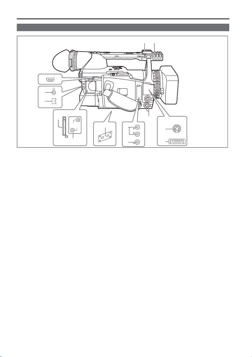
Description of parts
Description of parts ..................................... 12
Right side and rear side .................................. 12
Left side ........................................................... 13
Terminals and mounting parts .........................14
Remote control ................................................ 15
Preparation
The battery .................................................... 16
Charging .......................................................... 16
Installing and removing
the power supply ..................................17
Installing and removing the battery ................. 17
Connecting and disconnecting the power cord
... 17
Adjusting the hand strap ............................. 18
Attaching the shoulder strap ....................... 18
Detaching and attaching the lens hood .....18
The remote control ....................................... 19
Insert the battery ............................................. 19
Remote control setup ......................................19
Turn on/off the camera ................................. 20
Tally lamp ......................................................20
Viewfi nder .....................................................21
Using the viewfi nder ........................................21
Using the LCD ................................................. 22
Emphasizing outlines ...................................... 22
Adjusting the screen display ............................ 23
Setting the calendar ..................................... 24
Shooting
Basic shooting operations (P2 card) .......... 25
Preparing to shoot using a P2 card ................. 25
Shooting in auto mode .................................... 25
Checking photos taken (REC CHECK) ...........26
P2 card access lamps .....................................26
Protecting against a possible erasure .............26
Formatting P2 cards ........................................ 27
Recording times .............................................. 27
Remove the P2 card ........................................ 28
Basic shooting operations
(Cassette tape) ...................................... 29
Preparing to shoot using a tape ...................... 29
Shooting in auto mode .................................... 29
Checking scenes taken (REC CHECK) ........... 30
Remove the cassette tape ............................... 30
Cassette tapes ................................................ 31
Using SD memory cards .............................. 32
Installing and removing the SD memory card . 32
Formatting SD memory card ...........................32
Cautions in using SD memory cards ............... 32
Using the zoom function .............................. 33
Variable frame rates (VFR) ........................... 34
Native recording ..............................................35
Standard recording .......................................... 35
Using variable frame rates (VFR) .................... 36
Shooting in 1080i/480i progressive mode .. 37
Shooting in manual mode ............................ 38
Switching to manual mode .............................38
Manual focusing .............................................38
Using focus assist ............................................ 38
Iris adjustments ...............................................39
Adjusting the gain ............................................ 39
Light intensity adjustments .............................. 39
Adjusting the white balance ............................. 40
Shooting techniques for different targets .. 42
Low-angle shooting .........................................42
Self-portrait shooting ......................................42
Zebra pattern .................................................. 43
Marker ............................................................. 43
Checking and displaying shooting status ........44
Changing the image size ................................. 44
Optical Image Stabilizer .................................. 45
Adding effects to images ................................. 45
Using the USER buttons ................................. 45
Backlight compensation ................................... 45
Color bars ........................................................ 45
Adjusting the volume while shooting ...............46
Backup recording ............................................ 46
Pre-recording (PRE REC) ...............................47
Interval recording (INTERVAL REC) ................ 47
One-shot recording (ONE-SHOT REC) ........... 47
Loop recording (LOOP REC) .......................... 48
2-slot continuous recording .............................48
Shot mark function .......................................... 48
Text memo recording ....................................... 48
Finding specifi c scenes(image search) ........... 49
Index recording ................................................ 49
Adjusting the shutter speed ........................ 50
Synchro scan ................................................... 51
Switching Audio Input .................................. 52
Using the built-in microphone .......................... 52
Using another microphone
and audio equipment ................................... 52
Adjusting the recording level ...........................53
Using scene fi les .......................................... 54
Changing scene fi le settings ...........................54
Saving scene fi les and other settings
on SD memory cards ............................ 56
Clip metadata ............................................... 57
6
Page 7

Using the Counter ........................................58
Counter display (P2 card / Tape) .....................58
Memory stop mode (Tape) .............................. 58
1394TC preset mode ...................................... 58
Charging the built-in battery/
Setting the time data ............................ 59
Recharging the built-in battery ........................ 59
Setting the time code ....................................... 59
Specifying the time code (TC PRESET) .......... 59
Setting user information .................................. 60
Playback
Basic playback operations (P2 card) .......... 62
Basic playback operations (Tape) ............... 63
Thumbnail screen ......................................... 64
Basic thumbnail screen operations ................. 64
Adding shot marks to clips .............................. 66
Clearing the thumbnail screen ......................... 66
Direct shooting functions ................................. 66
Thumbnail operations .................................. 67
Selecting the thumbnail display method
(THUMBNAIL) ............................................. 67
Deleting clips and formatting cards
(OPERATION) ............................................. 69
Checking the clip or card information
(PROPERTY) ..............................................70
Uploading the metadata (META DATA) ............ 72
Useful playback functions ........................... 73
Variable speed search (P2 card / Tape) ........... 73
Slow playback (P2 card / Tape) .......................73
Fast forward/rewind playback (P2 card) ..........73
Fast forward/rewind playback (Tape) ............... 73
Frame-by-frame playback (P2 card / Tape) ...... 74
Clip skip (P2 card) ........................................... 74
End search (Tape) ........................................... 74
Index search (Tape) ......................................... 75
Adjusting the volume (P2 card / Tape) ............. 75
Viewing images on a television
(P2 card / Tape) ...........................................75
Checking the date and time (P2 card / Tape) .. 75
Editing
Connecting external units ...........................76
Headphones .................................................... 76
External microphone ....................................... 76
Computer (non-linear editing/fi le transfer) ....... 77
Hard disk drive (data copying) ......................... 77
Digital video equipment (Dubbing) ..................78
Video deck (Dubbing) ...................................... 79
TV/Monitor (playback/dubbing) ........................ 79
Audio dubbing .............................................. 80
Nonlinear editing with P2 card
(PC mode) .............................................. 82
Copying from P2 cards to the hard disk drive
(1394 HOST mode) ................................ 84
Warnings ......................................................... 85
Dubbing ......................................................... 86
Dubbing the contents of P2 cards onto a tape
(dubbing mode) ........................................... 86
Digital input/output (P2 card/Tape) .................. 87
Analog output (P2 card/Tape) .......................... 88
Analog input (Tape) .........................................89
Displays
Screen displays ............................................ 90
Regular displays .............................................. 90
Warnings ......................................................... 93
Setting the DISPLAY items .............................. 95
Menus
Using the setup menus ................................ 96
Using the menus ............................................ 96
Initializing the menu settings ..........................97
Setup menu structure ..................................98
Camera mode menu ........................................ 98
MCR/VCR (playback) mode menu .................. 99
Dubbing mode menu ....................................... 99
Setup menu list ........................................... 100
SCENE FILE screen ...................................... 100
CAMERA SETUP screen ..............................102
SW MODE screen ......................................... 103
AUTO SW screen ..........................................105
RECORDING SETUP screen ........................ 106
PLAYBACK FUNCTIONS screen .................. 109
DUBBING SETUP screen .............................111
AV IN/OUT SETUP screen ............................ 111
DISPLAY SETUP screen ............................... 112
CARD FUNCTIONS screen .......................... 114
OTHER FUNCTIONS screen ........................ 114
OPTION MENU ............................................. 118
Reference
Before calling for service ........................... 119
Operating precautions ............................... 123
Updating the driver in the camera ............125
Condensation.............................................. 125
System resetting ......................................... 126
Cleaning ...................................................... 126
Video Heads ................................................ 127
Storage Precautions ................................... 128
Recording format ........................................ 129
Specifi cations ............................................. 130
Before use
7
Page 8
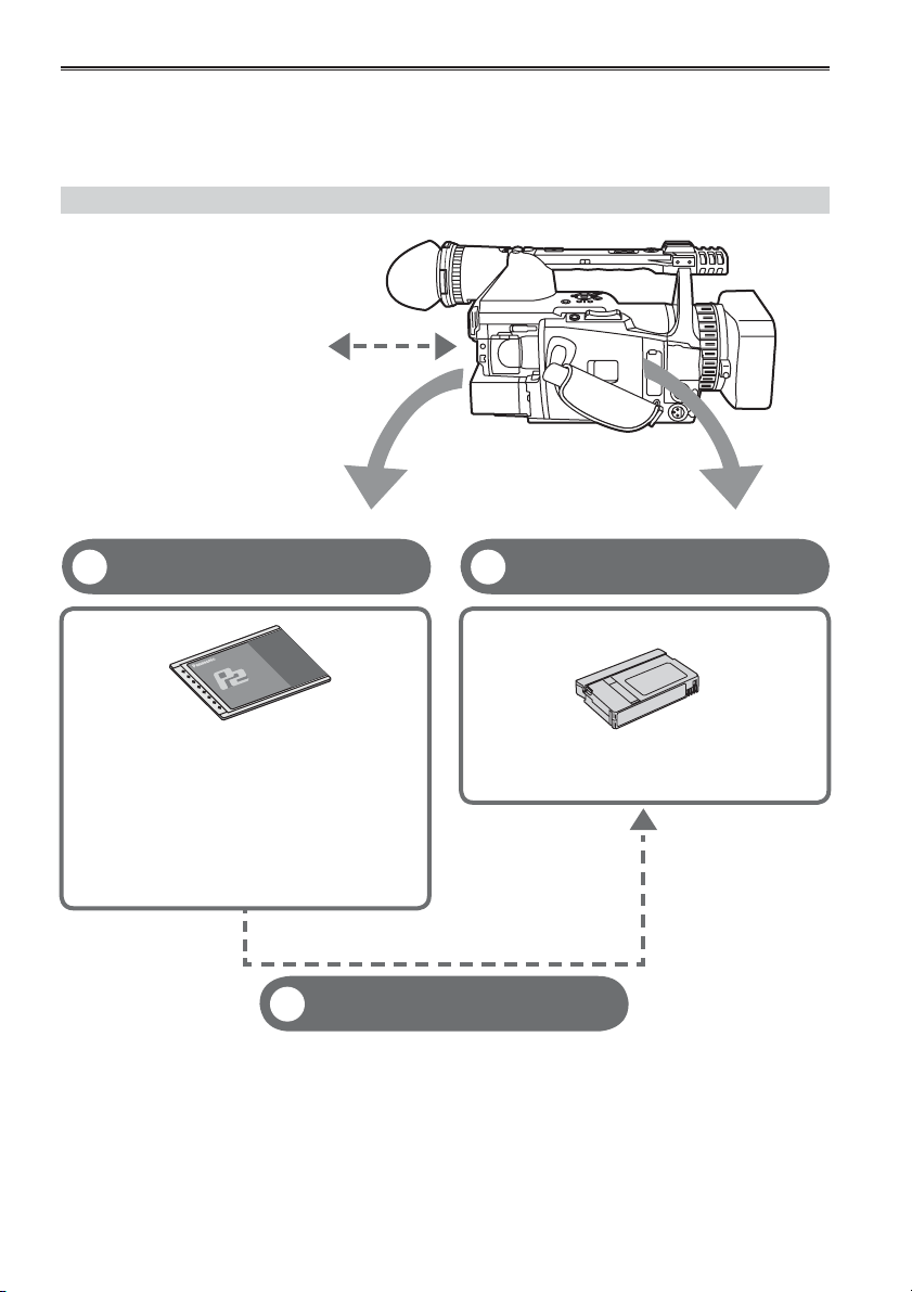
Outline of operations
This unit is compatible with P2 (Professional Plug-in) cards or DV cassette tapes.
The P2 card has a large capacity with a high transfer rate, and allows you sophisticated movie-making on
this handy camera, including HD (High Defi nition) recording and smooth editing/dubbing.
Flow of shooting, playing and saving
The setting values such as the user
fi le are saved to and read from the
SD memory card.
P2 mode shooting and playback
1
(Pages 25 and 73)
P2 card
You can use the following features:
• HD (High Defi nition) recording
• Multi format recording
• Variable frame rates
Slow & quick motion recording
• Maximum 4 channel uncompressed digital
audio recording
• DV recording (480i)
Dubbing mode (Page 86)
3
Dubbing mode is a function for down-converting contents recorded in
HD (1080i, 720P) on the P2 card to an DV format (480i) and recording it
to tape. You can record onto DV tape contents that have a slow & quick
motion effect.
This is useful when backing up images and checking images on AV
equipment.
Cassette tape shooting and
2
playback (Pages 29 and 73)
DV cassette tape
• DV recording (480i)
• Dubbing mode recording from a P2 card is
possible.
• You cannot simultaneously shoot on both the P2 card and the DV cassette tape.
• High-defi nition (HD) recording to a DV tape is not possible.
8
Page 9
Saving and editing on external devices
P2 card
USB2.0 (Windows)
IEEE1394 (Macintosh)
PC mode (Page 82)
4
The data (fi le) is transferred for nonlinear
editing on your computer or other unit.
Computer
1394 host mode (Page 84)
5
The unit directly controls the external hard
disk drive, and transfers the data (fi le) to it.
External hard disk
Before use
DV cassette tape
AV cable
Component
video cable
IEEE1394 (SBP-2)
IEEE1394
(Windows/Macintosh)
Video equipment
/Television
Computer
Memory card recorder
The contents can be transferred as a data
stream (digital dubbing).
Serial Bus Protocol-2
9
Page 10
Read this fi rst!
Always take some trial shots before actual shooting.
• When shooting important events (such as weddings), always take some trial shots and check that the
sound and images have been recorded properly before actual shooting.
Be sure to check and set the calendar and time zone.
• These settings affect the control and playback sequence of the recorded contents. Before making a
recording, set and check the calendar and time zone. (Page 24)
Panasonic makes no guarantees for your recordings.
• Please understand that Panasonic makes no guarantees for your recordings in cases where images and/
or sound were not recorded as you intended due to problems with the camera-recorder or cassette.
Respect copyrights
• Copyright laws forbid the use of video and audio material you have recorded for any purpose other than
your own personal enjoyment. Remember that restrictions apply to the shooting of certain material even if
it is intended for private use.
Caution regarding laser beams
• The CCD may be damaged if it is subjected to light from a laser beam.
When using the camera-recorder in locations where laser irradiation equipment is used, be careful not to
allow the laser beam to shine directly on the lens.
Notes when connecting a DV (IEEE1394) cable
• Windows:
Before connecting, turn off the main unit power, and check the shape and orientation of the terminal.
• Macintosh:
After turning on the power of the Apple Macintosh computer, check the shape and orientation of the
terminal, and then connect the cable.
(Pages 77, 78)
Media that can be used in this unit
The following media can be used in this unit. For details, refer to the respective pages.
• P2 card (Page 27)
• Digital video cassette tape (Page 30)
• SD memory card (Page 32)
Mounting the camera-recorder on a tripod
The tripod mounting hole is 5.5 mm deep. Do not force
the tripod screw beyond this depth.
You can damage the camera-recorder if you use any
screw other than 1/4-20UNC.
For other usage notes, see page 123.
10
Attach the tripod to the tripod hole
Page 11
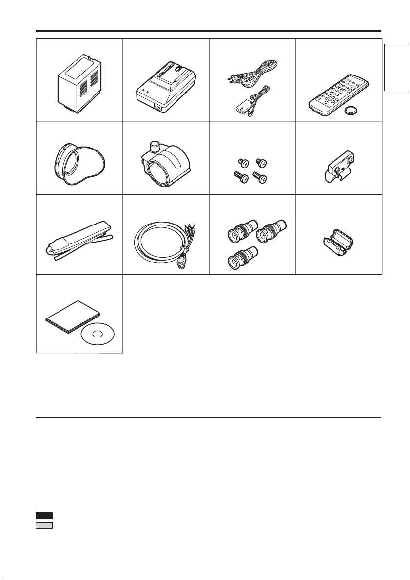
Accessories
1
Battery
AC Adapter AC power supply cord
/DC cord
Wireless remote
control and button
battery (CR2025)
Before use
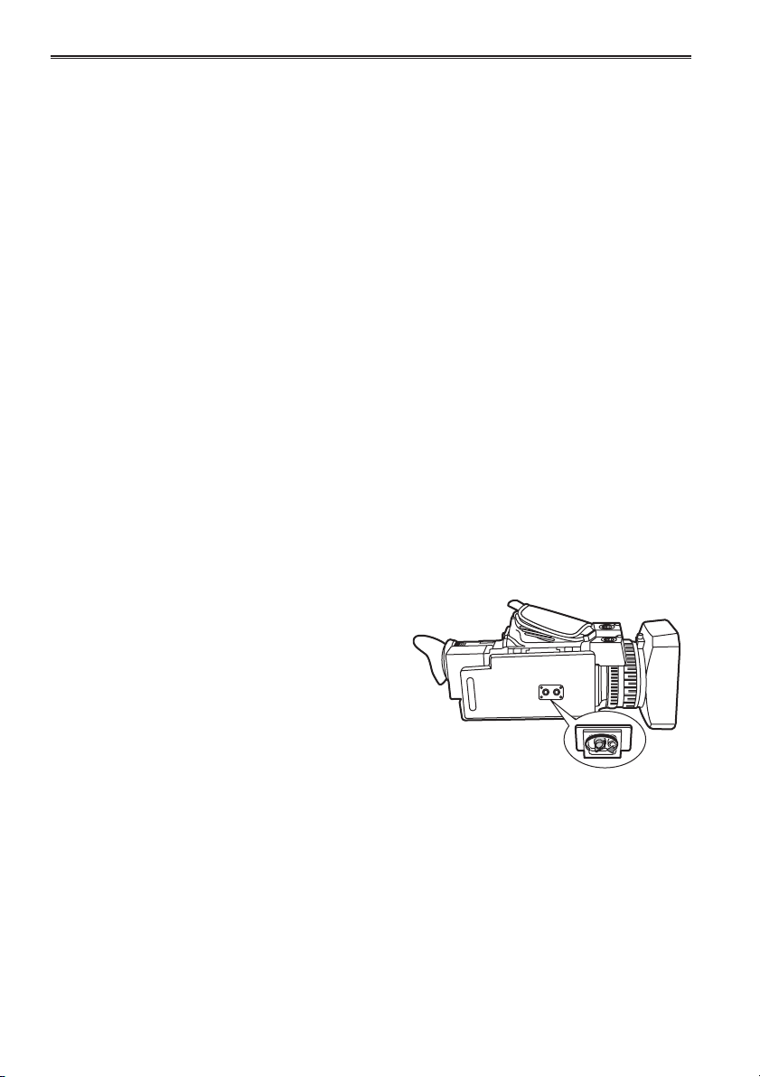
Microphone holderEye cup
Shoulder belt Component
video cable
Documents and CDs
A lens hood cap (page 18) and INPUT 1/2 terminal (page 14) cover are
attached to the camera-recorder.
1 For part numbers for the battery, see “OPTIONAL UNITS”. (Page 132)
2 When using 1394 cable (sold separately), install a ferrite core on the end nearest the PC. (Page 78)
6-mm screws (2)
12-mm screws (2)
PIN-BNC conversion
cable (3)
Microphone holder
adapter
Ferrite core
2
About this manual
Note concerning illustrations in these instructions
• Illustrations (camera-recorder, menu screens, etc.) in these operating instructions differ slightly from the
actual camera-recorder.
References
• References are shown as (Page 10).
Icons
Explanations specifi c to the media used are identifi ed by the icons below.
P2
: Explanations for P2 card usage only.
TAPE
: Explanations for tape usage only.
11
Page 12
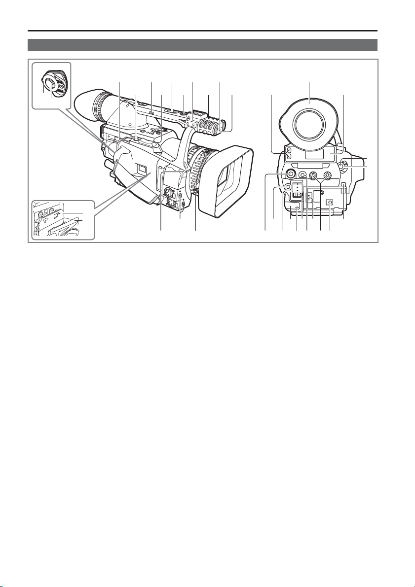
Description of parts
Right side and rear side
357
68
1
2
H
S
U
P
13
14
4
1 POWER switch (Page 20)
2 START/STOP button (Pages 25 and 29)
3 OPEN/EJECT switch (Page 29)
4 REC CHECK button (Pages 25 and 30)
5 HANDLE ZOOM switch (Page 33)
6 Zoom button (Page 33)
7 Handle zoom button (Page 33)
8 Handle START/STOP button
(Pages 25 and 29)
9 Pin hole (for zoom ring) (Page 13)
10 Built-in stereo microphone (Page 52)
11 Tally lamp (Front) (Page 20)
12 Remote control sensor (Front)
13 Cassette holder (Pages 29 and 30)
14 Cassette cover (Pages 29 and 30)
15 White balance sensor (Page 40)
16 INPUT 1/2 (audio input) switch (Page 52)
17 Lens hood screw (Page 18)
18 P2 card access lamp (x 2) (Page 26)
19 Viewfi nder (Page 21)
20 P2 card slot (x 2) (Page 25)
21 SCENE FILE dial (Page 54)
22 Mode button (Page 25 and 29)
23 Mode lamp (Page 25 and 29)
16
9
11
10 12
18
22 24 26 28 31
21 23 25 27 29
24 Remote control sensor (Rear)
25 Tally lamp (Rear) (Page 20)
26 MEDIA (P2/TAPE) switch
(Pages 25 and 29)
27 EVF DTL button (Page 22)
28 Power terminal (Page 17)
29 AUDIO control (Page 53)
30 DC INPUT terminal (7.9 V)
31 Battery release button (Page 17)
19
20
2
1
3015 17
12
Page 13
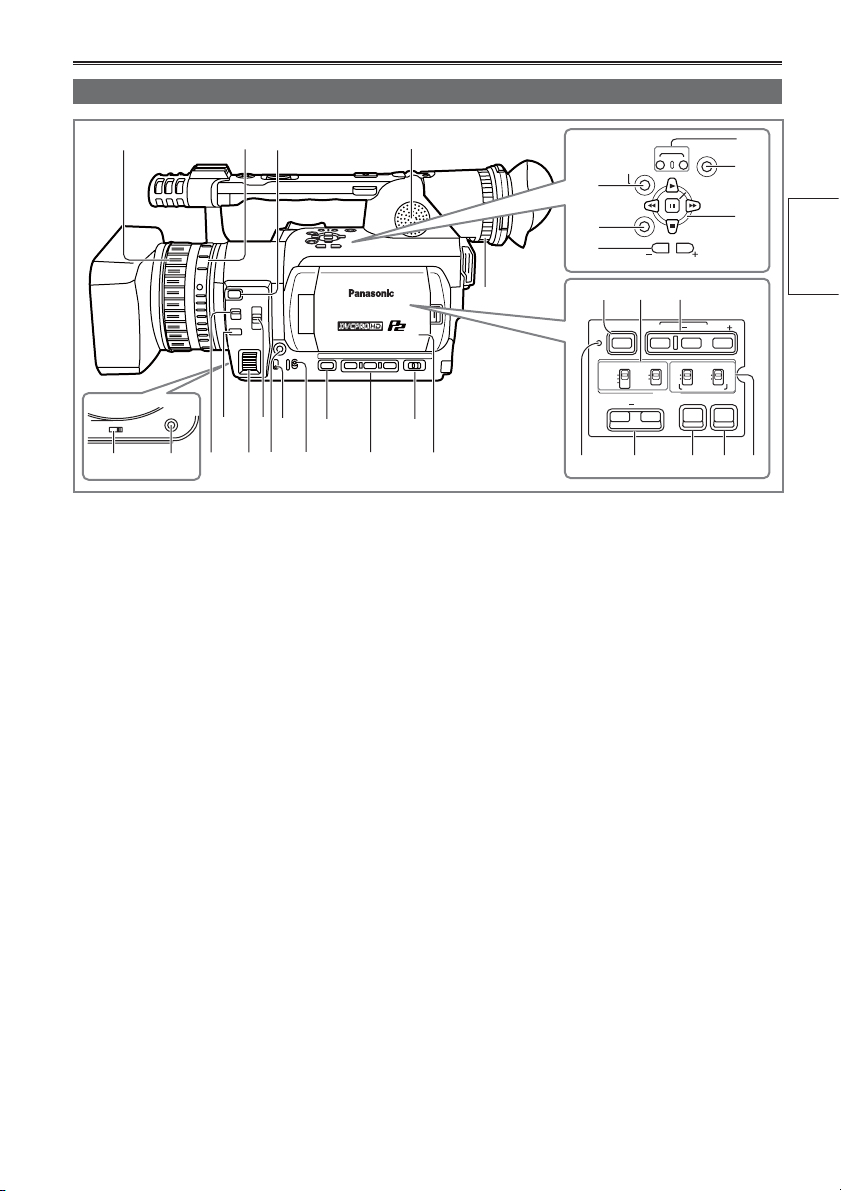
Left side
1
AWB
ZOOM
SERVO
MANUAL
56
324
8
10 12 14 16
11
97
13 15
1 Focus ring (Page 38)
2 Zoom ring (Page 33)
If you don’t need the zoom ring pin, fi t it into the
provided pin hole (Page 12) so that you don’t
lose it.
3 FOCUS ASSIST button (Page 38)
4 Built-in speaker (Page 75)
5 ZOOM switch (Page 33)
6 AWB button (Page 40)
7 FOCUS switch (Page 38)
8 PUSH AUTO button (Page 38)
9 IRIS dial (Page 39)
10 ND FILTER switch (Page 39)
11 IRIS button (Page 39)
12 GAIN switch (Page 39)
13 WHITE BAL switch (Page 40)
14 DISP/MODE CHK button (Page 44)
15 USER button (Page 45)
16 AUTO/MANUAL switch (Pages 25 and 29)
17 LCD monitor (Page 22)
18 Diopter adjustment dial (Page 21)
19 AUDIO DUB/THUMBNAIL button
(Pages 65 and 80)
20 MENU button (Page 96)
REC
MENU
AUDIO MON/VAR
SHUTTER
INT(R)
INPUT 2ONOFF
AUDIO
END SEARCH
SET
PAGE/
SPEED SEL
INPUT 1 INPUT 2
MIC POWER +48V
ZEBRA OIS
ON
OFF
17
18
AUDIO
DUB/
THUMBNAIL
19
20
21
25 26 27
BARS
RESET
CH 1 SELECT CH 2 SELECT
INT(L)
INPUT 1
INPUT 2
COUNTER RESET/TC SET
28 29 30 31 32
21 PAGE, AUDIO MON/VAR button
(Pages 46 and 73)
22 REC button (Page 87)
23 END SEARCH button (Page 74)
24 Operation button (Page 96)
25 BARS button (Page 45)
26 CH1, CH2 SELECT switch (Page 52)
27 SHUTTER - SPEED SEL button (Page 50)
28 RESET button (Page 126)
29 COUNTER - RESET/TC SET button (Page 58)
30 ZEBRA button (Page 43)
31 OIS button (Page 45)
32 INPUT1, 2 switch (MIC POWER +48 V)
(Page 52)
22
23
24
of parts
Description
13
Page 14
Description of parts (continued)
Terminals and mounting parts
USB 2.0
3
4
1394
5
CAM REMOTE
6
ZOOM SS
FOCUS IRIS
7
1 Light shoe
2 Microphone shoe (Page 76)
3 USB terminal (Mini-B) (Pages 77 and 82)
4 PHONES jack (3.5 mm stereo mini jack)
(Page 76)
5 1394 terminal (Page 77)
6 SD memory card slot (Pages 32 and 56)
7 CAM REMOTE jack
FOCUS/IRIS (3.5 mm mini jack)
You can connect a remote control unit to control
the FOCUS and IRIS (aperture).
ZOOM S/S (2.5 mm super mini jack)
You can connect a remote control unit to control
zoom and start/stop of recording.
8 Tripod hole (Page 10)
9 AUDIO IN/OUT CH1/CH2 terminal (Page 79)
10 VIDEO IN/OUT terminal (Page 79)
11 INPUT 1/2 terminal (XLR, 3 pin)
(Pages 52 and 80)
12 S-VIDEO IN/OUT terminal (Page 79)
13 COMPONENT OUTPUT terminal (Page 79)
8
12
10
11
CH1
9
IN/
AUDIO
OUT
CH2
IN/
OUT
VIDEO
12
13
S-VIDEO
IN/OUT
COMPONENT
OUT
Do not connect any equipment except the
remote controller to the remote control jack.
If any equipment except the remote controller
is connected, the pictures will be affected e.g.
appear bright or out of focus.
14
Page 15

Remote control
The following buttons are for functions that cannot
be executed on the camera-recorder.
• PHOTO SHOT
• MULTI/P-IN-P
• STORE
• PB. ZOOM
1
2
3
COUNTER
6
7
8
9
12
10
STILL A DV
11
SELECT
16
STORE
OFF/ON
P. B .DIGITAL
OSD
MULTI/
P-IN-P
INDEX
• TITLE
• SELECT
• OFF/ON
PHOTO
SHOT
STILL A DV
MENU
ITEM
START/
VOL +
-
DATE/
TIME
RESET TITLE
REC A.DUB
PLAY/REW FF/
PAUSE
STOP INDEX
VAR.
SEARCH
STOP
ZOOM
PB.
ZOOM
14
4
5
15
13
10
11
17
SET
1 DATE/TIME button (Page 75)
2 OSD button (Page 75)
3 COUNTER button (Page 58)
Same function as the COUNTER button on the
main unit.
4 COUNTER RESET button (Page 58)
Same function as the COUNTER RESET
button on the main unit.
5 A.DUB button (Page 80)
Same function as the AUDIO DUB button on
the main unit.
6 REC button (Page 87)
Used during VCR mode
7 PLAY button (
) (Page 62)
8 /REW button ( ) (Page 62)
9 PAUSE button (
) (Page 62)
Like the operation buttons of the camera,
MENU operations are performed using SET
button.
10 STILL ADV button (
11 INDEX buttons (
12 STOP button (
13 FF/
button ( ) (Page 62)
, ) (Page 73)
, ) (Page 75)
) (Page 62)
Buttons for shooting and volume control
14 START/STOP button
Same function as the START/STOP button on
the main unit.
15 ZOOM/VOL buttons (Pages 33 and 75)
of parts
Description
16 VAR. SEARCH button (Page 73)
17 MENU button
Functions the same as the MENU button on the
camera.
[
], [ ], [ ], [ ] buttons
Function the same as the
, , , buttons
on the camera.
15
Page 16
The battery
Charging
Before using the battery, fully charge it with the AC
adapter.
Keep a spare battery with you.
1 Align the battery with the “ ” marking on
the AC adapter, place it fl at, and slide it in
the direction shown below.
• You cannot charge the battery if the DC cord
is connected to the DC OUT connector, so
disconnect it fi rst.
2 Plug the AC cord into the power outlet.
• The POWER lamp and CHARGE lamp on the
AC adapter light, and charging begins.
• If the CHARGE lamp does not light when
attached, detach the battery and then attach it
again.
POWER
CHARGE
3 When the battery is charged, the CHARGE
lamp on the AC adapter goes out.
4 Slide the battery and remove it.
Recording time of included battery
Recharging time Continuous recording time
Approx. 330 min. Approx. 140 min.
• The times given above are approximate for when
scenes are shot in the DVCPRO HD mode on a
P2 card while using the viewfi nder.
• The times apply when the ambient operating
temperature is 68°F (20°C) and humidity is 60%.
Charging may take longer at other temperatures
and humidity levels.
• Keep metal objects (such as necklaces
and hairpins) away from the battery. Shortcircuiting may occur across the terminals,
causing the battery to heat up, and you may
seriously burn yourself if you touch the
battery in this state.
• The battery becomes hot while it is being used
or charged. The camera-recorder itself also
becomes hot during use.
• The recordable time reduces if you repeatedly
start and stop recording.
• Discharge the battery before storing it. When
storing it for an extended time, charge it at least
once a year, use up its charge in the camerarecorder, and then store it again.
• If the battery is extremely hot or cold, the
CHARGE lamp will blink several times before
charging starts.
• If the CHARGE lamp continues to blink even
when the battery temperature is normal, there
may be something wrong with the battery or AC
adapter. Contact your dealer.
• The battery takes longer to charge when it is
warm.
• The AC adapter can interfere with radio reception
so keep radios at least 1 meter away from it.
• The AC adapter may make some noise when you
are using it, but this is normal.
• You cannot charge the battery when supplying
power to the camera-recorder from the AC
adapter.
• Operation of battery pack CGR-D16 (1600mAh)
(sold separately) is not guaranteed.
16
Page 17
Installing and removing the power supply
Installing and removing the battery
Installation
Insert the battery until it clicks into place.
Removal
1 Set the POWER switch to OFF, and check
2 Remove the battery while pressing the
Connecting and disconnecting the power cord
Installation
1 Connect the DC cord to the AC adapter.
Removal
1 Set the POWER switch to OFF, and check
2 Plug the AC power supply into the power
outlet.
2 Remove the DC cord’s battery connector
3 Insert the DC cord’s battery connector until
it clicks into place.
3 Disconnect the AC power supply cord from
that the mode lamp is off.
battery release button.
• Support the battery with your hand to ensure
that it will not fall.
Battery release
Mode lamp
that the mode lamp is off.
while pressing the battery release button.
the power outlet.
button
Preparation
DC cord’s battery
connector
• You cannot charge the battery when supplying
power to the camera-recorder from the AC
adapter.
CAUTION:
• This unit can be operated at a voltage in the
range of 100-240V AC. An AC plug adapter may
be required for voltages other than 120 V AC. If
a conversion plug is required, consult with your
dealer as to which one is to be purchased.
• Disconnect the AC power supply cord from the
power outlet when the unit is not going to be
used.
17
Page 18
Adjusting the hand strap
Adjust the hand strap to suit your hand.
1 Open the cover and adjust the length.
2 Close the cover.
• Make sure the cover is fully closed.
Attaching the shoulder strap
Attach the shoulder strap and use it as a precaution against dropping the camera.
20 mm or more
20 mm or more
Detaching and attaching the lens hood
Detaching the lens hood
• Loosen the screw and turn the lens hood
counterclockwise to detach it.
Attaching the lens hood
• Turn the lens hood clockwise and fi x in position
with the screw.
• Be sure to attach the lens hood cap to protect the
lens when not in use.
18
Screw
Page 19
The remote control
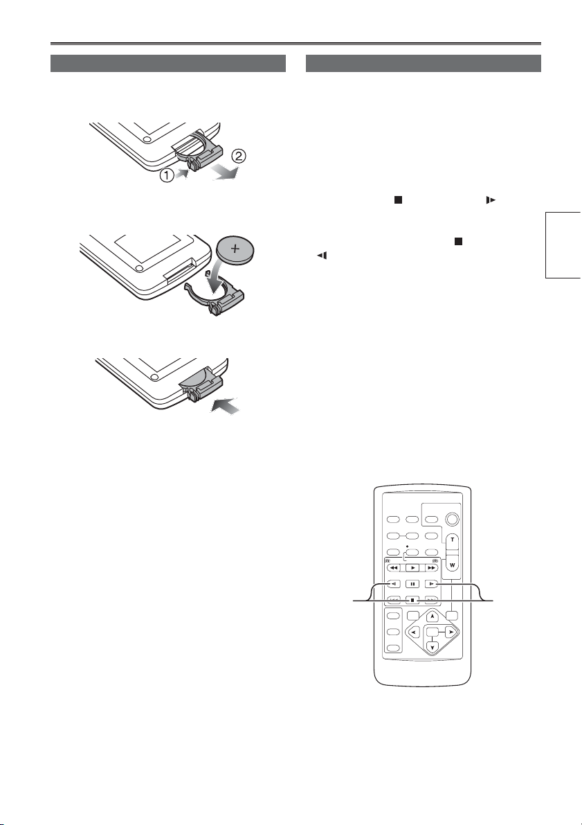
Insert the battery
1 Push the catch in the direction shown by
arrow (1) to remove the holder.
2 Insert the battery with the “+” marked side
facing up.
3 Return the holder to its original position.
• When the battery (CR2025) has run out, replace
it with a new one. (The battery lasts about one
year, depending on the frequency of use.)
If the remote control unit fails to work even when
it is operated near the camera-recorder’s remote
control sensor, the battery has run out.
• Keep the battery out of the reach of children.
Remote control setup
When using two camera-recorders simultaneously,
set this camera-recorder and the remote control
to either [VCR1] or [VCR2] so the remote control
does not operate the wrong camera-recorder by
mistake.
Setting
• Wireless remote control
Press the STOP (
at the same time to set the remote control unit for
use with VCR1.
Alternatively, press the STOP (
(
) buttons at the same time to set the remote
control unit for use with VCR2.
When the battery in the remote control unit is
replaced, the remote control unit is set for use
with VCR1.
• Camera
In the setup menus, OTHER FUNCTIONS
screen, REMOTE, set to VCR1 or VCR2. (Page
114)
If different settings are used for the camerarecorder and remote control unit, “REMOTE” lights
in red on the viewfi nder and LCD monitor.
VCR2 VCR1
) and STILL ADV ( ) buttons
) and STILL ADV
START/
DATE/
PHOTO
STOP
TIME
SHOT
OSD
COUNTER
RESET TITLE
REC A.DUB
PLAY/REW FF/
PAUSE
STILL ADV
STOP INDEX
VAR.
SEARCH
ZOOM
VOL +
-
PB.
ZOOM
MENU
SET
ITEM
MULTI/
P-IN-P
STILL ADV
INDEX
SELECT
STORE
OFF/ON
P.B.DIGITAL
Preparation
19
Page 20
Turn on/off the camera
While pressing the lock release, move the POWER
switch to ON or OFF.
Turn on the camera:
The mode lamp (CAMERA) lights red (CAMERA
mode) and the camera is now in the shooting
standby mode.
Turn off the camera:
The red mode lamp goes out.
• Power saving mode
The camera-recorder performs as follows when
you pause or leave it in standby mode for about
5 minutes, and do not perform any specifi ed
operations.
ON: The camera recorder turns off automatically
OFF: Do not switch OFF the camera. In the TAPE
mode, however, put the cylinder head alone
in a stopped (standby) status.
See the setup menus, OTHER FUNCTIONS
screen, POWER SAVE (page 117) for details.
• When the operation mode buttons fl ash in
sequence starting with the top one and the power
then goes off, it means that there is no charge left
in the battery. Recharge the battery.
Mode button
MCR VCR
Mode lamp
CAMERA
ON
OFF
DUBPC
Lock release
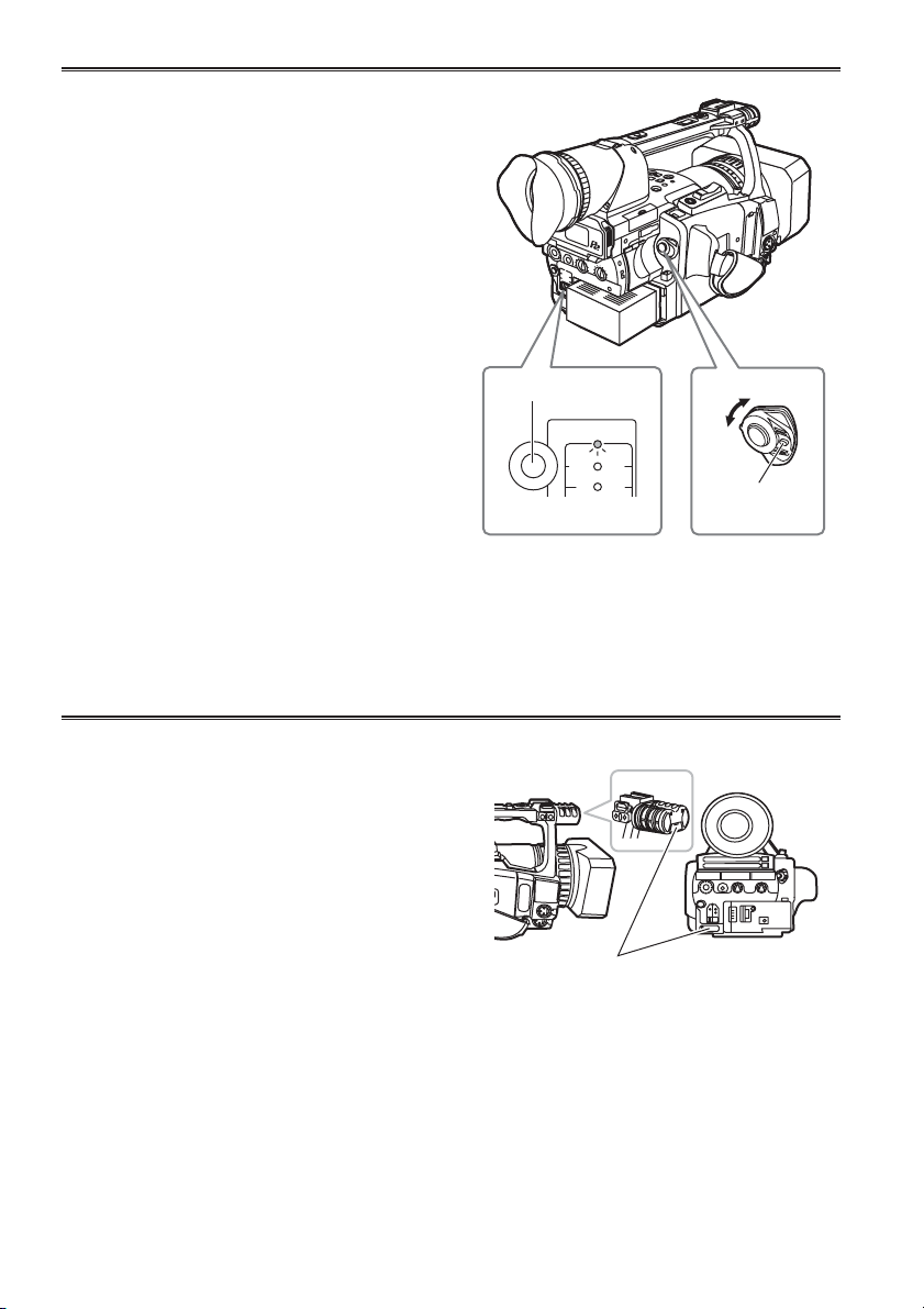
Tally lamp
The tally lamp can be made to light up during
shooting by selecting “ON” as the REC LAMP
set-ting in the OTHER FUNCTIONS screen. (Page
115)
When the camera-recorder is in any of the
following states, the tally lamp blinks.
• When an operation initiated by the remote control
unit has been received (8 blinks/sec.)
• When shooting starts in the TAPE mode (8 blinks/
sec.)
• When the end of the tape is reached (4 blinks/
sec.)
• When trouble occurs regarding tape running
systems (4 blinks/sec.)
• When the remaining battery capacity runs out (4
blinks/sec.)
• When the available recording space on the P2
card or tape or the battery power is low (1 blinks/
sec.)
• When removing the P2 card during access (4
blinks/sec.)
• When there is no recording space left on the P2
card (4 blinks/sec.)
20
Tally lamp
Page 21
Viewfi nder
This camera has two viewfi nders; one is a
miniature LCD in the viewfi nder and the other is a
retractable 3.5-inch LCD.
Use the viewfi nder that best suits the application
and shooting conditions.
• The brightness and hue may differ between the
images appearing on the viewfi nder and LCD
monitor and those displayed on a TV monitor.
To see how the fi nal images will appear, check
them on a TV monitor.
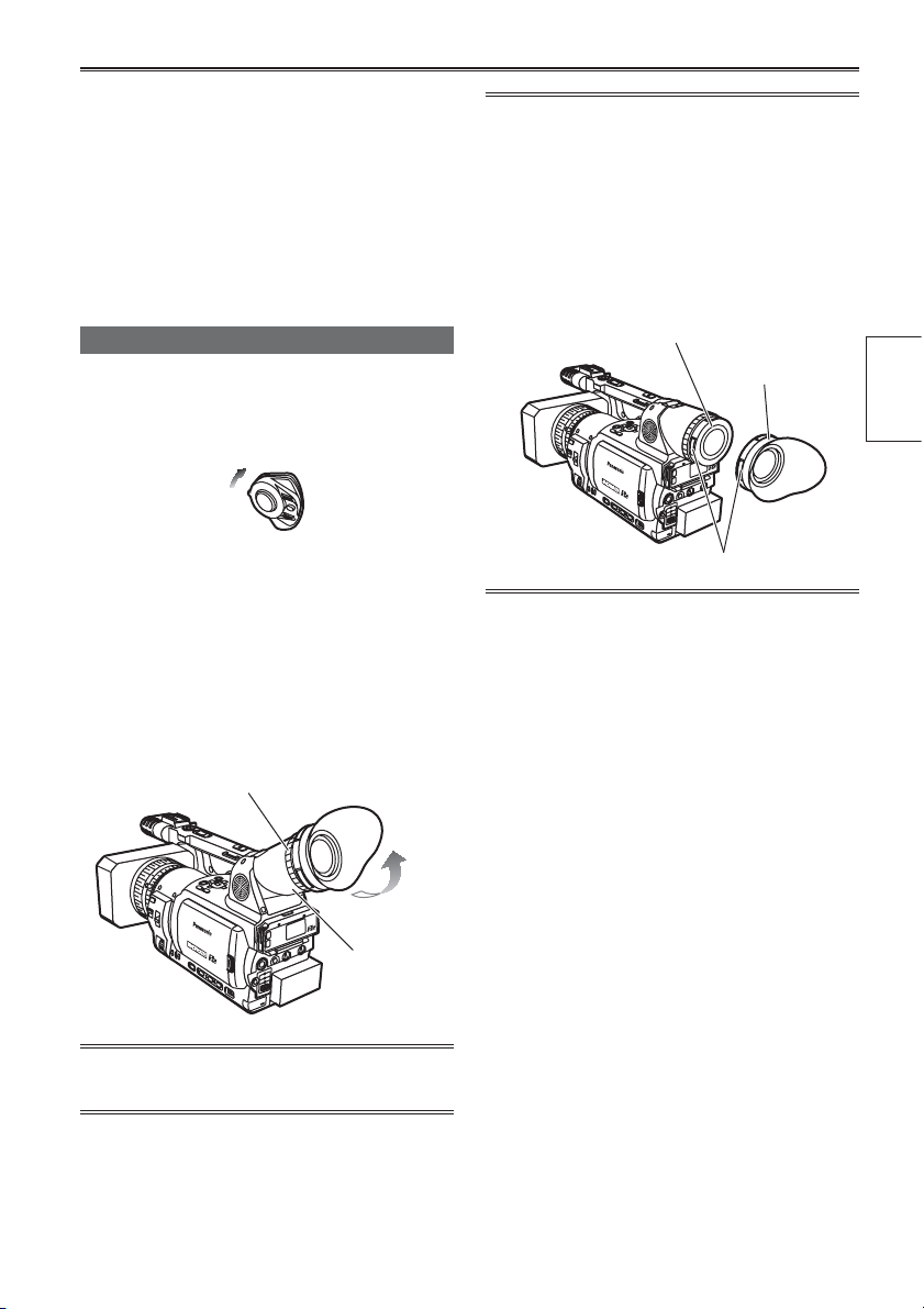
Fitting the eye cup
Attach the eye cup by aligning the projections on
the eye cup holder and eye cup and fi tting them
together.
• Turning the eye cup after attaching it may
cause the eye cup holder to come off. If the
eyecup holder does come off, see “Cleaning the
Viewfi nder” (page 126) for details on how to refi t
it.
Using the viewfi nder
1 Set the POWER switch to ON and check that
images appear in the viewfi nder.
• Keep the LCD monitor closed.
ON
2 Adjust the viewfi nder’s angle so that the
screen is positioned where it is easiest to
see.
• You can move the view fi nder out to about 90°
perpendicular to the camera.
3 Adjust the diopter adjustment lever so
that you can see the characters on the
viewfi nder screen clearly.
Viewfi nder diopter dial
Eye piece
Eye cup holder
Eye cup
Preparation
Projection
Do not point the eye piece at the sun.
Doing so may damage the parts inside.
21
Page 22

Viewfi nder (continued)
Using the LCD
1 Set the POWER switch to ON.
2 Press the OPEN button in the direction
shown by arrow (1) to open the LCD.
It can open out to 120 degrees. Do not try
to open it further as this will damage the
camera.
3 Position the LCD monitor where it is easiest
to see.
• The monitor can be rotated 180° toward the
lens and 90° toward you.
• Do not apply unnecessary force to the open
LCD. This can damage the camera.
Emphasizing outlines
Emphasizing the outlines of the images you see
in the viewfi nder or on the LCD makes it easier to
focus.
Emphasizing the outlines does not effect the
images you shoot.
1 In CAMERA mode, press EVF DTL.
• “EVF DTL ON” appears on the screen for
about 2 seconds.
EVF DTL button
Press EVF DTL again to return to the original
display. “EVF DTL OFF” appears on the screen for
about 2 seconds.
• Ensure the LCD is fully closed.
• Both the LCD and viewfi nder come on when
you have rotated the LCD to face in the same
direction as the lens for self-portrait shooting.
22
Page 23

Adjusting the screen display
1 Set the POWER switch to ON. (Page 20)
2 Press the MENU button.
SET
Operation button
MENU
• For menu operation (Page 96)
• You can also use the menu buttons on the
remote control. (Page 15)
3 Viewfi nder adjustments
Set YES under EVF SET on the setting menu
DISPLAY SETUP screen.
LCD monitor adjustments
Set YES under LCD SET on the setting menu
DISPLAY SETUP screen.
4 Select the item to be set using the or
operation button.
5 Adjust the selected item using the or
operation button.
6 Press MENU three times to exit the menus.
Preparation
• You can return the settings for EVF SET and LCD
SET to the factory settings by selecting the item
and pressing COUNTER RESET (if it is possible
to change the item at that time).
• The viewfi nder remains on when you open
the LCD if you have set the EVF MODE in the
DISPLAY SETUP screen to ON.
• The viewfi nder display can be in color or black
and white. (See the setup menus, DISPLAY
SETUP screen, EVF COLOR.) The resolution is
the same for both of them.
23
Page 24

Setting the calendar
The CLOCK SET value is recorded in the contents
(clip), and affects the sequence of playback of the
thumbnails. Before carrying out recording, be sure
to check and set CLOCK SET and TIME ZONE.
This shows you how to adjust the calendar to 5:20
PM on December 25, 2005.
1 Set the POWER switch to ON. (Page 20)
2 Press the MENU button.
3 In the setup menus, OTHER FUNCTIONS
screen, TIME ZONE, set the time difference
from Greenwich mean time using the
operation button. (Page 116)
(Example of MENU in the TAPE mode)
SET
Operation button
MENU
• For menu operation (Page 96)
• You can also use the menu buttons on the
remote control. (Page 15)
or
Press the operation button to move the
6
setting item to MONTH.
7 Press the or operation button to set
MONTH to DEC.
8 Set DAY, HOUR, and MIN using the method
shown in steps 4 and 5.
• This is a 24-hour clock.
4 In the setup menus, OTHER FUNCTIONS
screen, CLOCK SET, select YES.
5 Press the or operation button to set
YEAR to 2005.
Choose a year between 2000 and 2030.
24
9 Press MENU three times to exit the menus.
• The clock can vary in accuracy so check that the
time is correct before shooting.
• When using the camera overseas, do not set the
CLOCK option to the current time, but instead
enter the time difference from Greenwich mean
time according to TIME ZONE.
Page 25

Basic shooting operations (P2 card)
P2
Preparing to shoot using a P2 card
1 Switch the MEDIA switch to “P2”.
2 Set the POWER switch to ON. (Page 20)
3 Lift up the viewfi nder and open the card slot
cover.
4 Insert the P2 card securely in the card slot.
• There are two card slots.
• Be absolutely sure to close the card slot
covers to keep the dust out.
2
ON
3
4
1
P2 TAPE
Lock
release
Shooting in auto mode
1 Turn the POWER switch to ON. (Page 20)
• Check that the mode lamp (CAMERA) is
lighted red. If not, press the mode button.
2 Switch the AUTO/MANUAL switch to AUTO
to select auto mode.
• “A” appears on the viewfi nder and LCD
screens.
• The focus, gain, iris and white balance are
adjusted automatically.
3 Press the START/STOP button (Red) on the
POWER switch to start shooting.
• Press again to return to the camera to the
shooting standby mode.
• Use the handle START/STOP button to make
it easier to shoot from low angles.
LCD side
2
AUTO MANUAL
Handle START/STOP
button
Shooting
Do not operate the MEDIA switch when the power
is switched ON.
If you attempt to operate the MEDIA switch, the
message “TURN POWER OFF” will be displayed.
In this case, switch OFF the power, and then switch
it ON again.
Mode button
CAMERA
MCR VCR
Mode lamp
REC CHECK
button
1
ON
3
DUBPC
Lock
release
25
Page 26

Basic shooting operations (P2 card) (continued)
Checking photos taken (REC CHECK)
In the shooting pause mode, press the REC
CHECK button.
A few seconds of the last thing you shot play.
• Note that this REC CHECK portion will also be
recorded to any equipment you have set up to
make backup recordings.
• Only the POWER and START/STOP buttons are
operable during REC CHECK.
• The REC CHECK function does not work when
PC, MCR or DUB has been selected as the
operation mode.
The HD recording(720P/60P) settings are already
made in the default mode.
(To view the current settings, see page 44.)
P2 card access lamps
CAMERA mode (MCR)
Lights green: Data can be saved onto the cards or
loaded from them.
Blinks green (slow): No available space on card,
card is write-protected
Lights orange: Slot that is the object of recording
Blinks orange : Data is now being accessed.
Blinks orange (fast): A card is now being
recognized.
Both lamps blink orange: Ejection of card during
access
Off: Cards have not been inserted or formatted.
Insertion of incompatible card.
P2 card access lamp
Protecting against a possible erasure
Switch the write-protect switch of the P2 card to
[PROTECT].
Write-protect switch
P2
PROTECT
PC mode (USB DEVICE)
Blinks orange: Data is now being accessed.
Off: A status other than access underway.
PC mode (1394 DEVICE)
Blinks orange: Connected
Off: Not connected
PC mode (1394 HOST)
Lights green: Access standby.
Blinks orange: Data is now being accessed.
Off: Cards have not been inserted or formatted.
Inser tion of incompatible card.
26
Page 27

Formatting P2 cards
P2
1 Press the mode button and set it to MCR
mode (the MCR/VCR lamp lights).
• Thumbnails are displayed.
2 Press the MENU button.
SET
Operation
button
MENU
MENU button
Mode button
CAMERA
MCR VCR
DUBPC
Mode lamp
3 On the menu, select OPERATION and then
FORMAT.
• A screen such as the one shown below
appears. Select the number of the slot
into which you inserted the P2 card to
be formatted. Select EXIT to cancel the
formatting.
• When you press the MENU button, the menu
display disappears.
4 Select YES on the confi rmation screen.
• The selected P2 card is formatted.
Recording times
Card model Capacity
AJ-P2C004HG 4 GB approx. 16 min. approx. 8 min. approx. 4 min. approx. 10 min. approx. 8 min.
AJ-P2C008HG 8 GB approx. 32 min. approx. 16 min. approx. 8 min. approx. 20 min. approx. 16 min.
• The AJ-P2C002SG (2 GB) card cannot be used.
• The displayed available space includes the management area, and so the space available for recording is
smaller than this.
• Concerning the division of clips recorded on P2 cards
When using a P2 card of at least 8 GB in this camera, if the continuous recording time for a single
session exceeds the time shown in the following table, recording will be automatically resumed as a
different clip. When performing a thumbnail operation (display, delete, restore, copy, etc.) on clips using
P2 cards, you can operate them as a single clip. When you are using non-linear editing software and a
PC, for example, the clips are displayed individually.
Recording Format Recording times
DVPRO HD
DVPRO50 approx. 10 min.
DVPRO/DV approx. 20 min.
• When using any other types of cards, the driver installed in the camera-recorder may need to be updated.
(Page 125)
• For the latest information not available in the Operating Instructions, visit the P2 Support Desk at the
following Web sites.
https://eww.pavc.panasonic.co.jp/pro-av/
1
DVCPRO
2-channel
audio
approx. 5 min.
DVCPRO50
4-channel
audio
*1 The 720P/30PN and 720P/24PN formats are not
DVCPRO HD
included in the DVCPRO HD recording format.
DVCPRO HD
1
720P/24PN
DVCPRO HD
720P/30PN
Shooting
27
Page 28

Basic shooting operations (P2 card) (continued)
Remove the P2 card
1 Lift up the viewfi nder and open the card slot
cover.
• Check that the P2 card access lamp is not
blinking orange.
2 Press the card eject button once, and when
the button has popped back up, press it
again.
3 Remove the P2 card.
1
Card eject button
2
3
• Do not eject a P2 card while its data is being
accessed or while it is being recognized after
insertion (the P2 card access lamp is blinking
orange).
• If a P2 card is ejected during formatting or while
its data is being accessed, “TURN POWER
OFF” appears in the viewfi nder, and a warning
is indicated by an alarm or tally lamp. If this
happens, turn the power off and back on again.
When a card is ejected during formatting:
Format the card again.
When a card is ejected while its data is being
accessed:
The data on the card will not be destroyed, but
the clips may be thrown out of order. Check the
clips and repair them. (For details on repairing
clips, see page 69.)
• During playback, a P2 card inserted into the
empty slot will not be recognized and the P2
card access lamp will not light. When playback is
completed, the P2 card recognition will begin.
• You can use ACCESS LED on the OTHER
FUNCTIONS screen to set the P2 card access
lamps so that they will always be off. In this case,
either turn off the power or wait until enough time
has passed after inserting the cards or stopping
operation before ejecting the cards.
• If a P2 card is ejected while thumbnails are
displayed, the thumbnail screen is released.
P2
28
Page 29

Basic shooting operations (Cassette tape)
TAPE
Preparing to shoot using a tape
1 Switch the MEDIA switch to “TAPE”.
2 Set the POWER switch to ON. (Page 20)
3 Slide the OPEN/EJECT switch in the
direction shown by the arrow to open the
cassette cover.
• The cassette holder opens automatically.
• The cassette holder will not open if the
camera is not supplied with power (AC
adapter or a battery).
4 Insert the cassette tape.
5 Press PUSH to close the cassette holder.
• Close the cassette cover only after the
cassette holder is completely in position.
ON
3
1
2
Lock
release
Shooting in auto mode
1 Turn the POWER switch to ON. (Page 20)
• Check that the mode lamp (CAMERA) is
lighted red. If not, press the mode button.
2 Switch the AUTO/MANUAL switch to AUTO
to select auto mode.
• “A” appears on the viewfi nder and LCD
screens.
• The focus, gain, iris and white balance are
adjusted automatically.
3 Press the START/STOP button (Red) on the
POWER switch to start shooting.
• Press again to return to the camera to the
shooting standby mode.
• Use the handle START/STOP button to make
it easier to shoot from low angles.
LCD side
2
AUTO MANUAL
Handle START/STOP
button
Shooting
P2 TAPE
45
H
S
U
H
S
U
P
Do not operate the MEDIA switch when the power
is switched ON.
If you attempt to operate the MEDIA switch, the
message “TURN POWER OFF” will be displayed.
In this case, switch OFF the power, and then switch
it ON again.
P
Mode button
CAMERA
MCR VCR
Mode lamp
REC CHECK
button
1
ON
3
DUBPC
Lock
release
29
Page 30

Basic shooting operations (Cassette tape) (continued)
Checking scenes taken (REC CHECK)
In the shooting pause mode, press the REC
CHECK button.
A few seconds of the last thing you shot play, and
then the camera returns to the shooting pause
mode.
• The REC CHECK function cannot be used
unless the recording is at least one second long.
• When recording backup images by connecting
the equipments using a 1394 cable, the images
will not appear during REC CHECK.
• The REC CHECK function does not work when
VCR or DUB has been selected as the operation
mode.
1
23
TAPE
Remove the cassette tape
1 Slide the OPEN/EJECT switch in the
direction shown by the arrow to open the
cassette cover.
• The cassette holder opens automatically.
• The cassette holder will not open if the
camera is not supplied with power (AC
adapter or battery).
• A tape cannot be ejected in P2 mode or
during recording in TAPE mode.
2 Remove the cassette.
3 Press PUSH to close the cassette holder.
• Close the cassette cover only after the
cassette holder is completely in position.
PUSH
H
S
U
H
S
U
P
P
30
Page 31

Cassette tapes
You can use tapes with this mark .
Use the following mini DV cassette tapes with this
camera-recorder.
AY-DVM63PQ Professional series tape
(60 minutes in SP mode)
AY-DVM63MQ Master series tape
(60 minutes in SP mode)
Do not use 80-minute miniDV cassette tapes.
Picture quality does not worsen if you shoot in LP
mode, but you may notice some block noise and
there may be other limitations.
Block noise and feature limitations occur in the
following situations.
• When you play a tape on other digital video
equipment that you have shot in LP mode on
this camera.
• When you play a tape in this camera that you
have shot in LP mode on other digital video
equipment.
• When you have shot in LP mode and try to play
it on other digital video equipment that doesn’t
have an LP mode.
• During slow motion or still-picture playback
• When using the camera’s search functions
Audio dubbing cannot be performed in the LP
mode as the tracks on the tape are narrower than
the heads.
Preventing accidental erasure
To prevent erasing the recordings on a tape by
accident, set the tab on the cassette to SAVE.
TAPE
Tape loading and unloading
• Tapes cannot be loaded or unloaded when the
MEDIA switch is set to P2.
• Do not try to insert or eject the tape by just
holding the cassette cover.
• Insert and remove cassette tapes after putting
the camera-recorder down on a stable, fl at
surface or hold it to keep it stable.
• Do not force the cassette holder while it is
moving. Trying to do so could damage the
camera.
• Close the cassette cover only after the cassette
holder is completely in position. Trying to close
the cover while the cassette holder is moving
could damage the camera.
• Close the cassette holder again if you are not
going to insert another tape.
• Do not open the cassette cover while you are
recording. Recording continues, and the open
cover allows outside light and dust to adversely
affect the tape.
Shooting
REC
SAVE
31
Page 32

Using SD memory cards
TAPE
You can use SD memory cards to save and load
SCENE fi les and USER fi les. (Page 56)
Installing and removing the SD
memory card
Installation
1 Open the cover, and insert the card while
making sure it is oriented in the proper
direction.
Access lamp
L
O
C
K
2 Close the cover.
Removal
1 Open the cover, and check that the access
lamp is not lit.
2 Press the card further into the unit, grasp
the card, and then remove.
3 Close the cover.
Formatting SD memory card
1 Switch the MEDIA switch to “P2”.
2 Set the POWER switch to ON. (Page 20)
3 Press the mode button and set it to MCR
mode (the MCR/VCR lamp lights).
4 Press the MENU button.
5 On the menu, select OPERATION, FORMAT
and then SD CARD.
• Select EXIT to cancel the formatting.
6 Select YES on the confi rmation screen.
• The selected SD memory card is formatted.
You can also format from the SD CARD FORMAT
option on the CARD FUNCTIONS screen. (Page
114)
Cautions in using SD memory cards
• SD memory cards used with the AG-HVX200
should conform to SD standards. Be sure to
format cards using the AG-HVX200.
To format SD memory cards using a personal
computer, download the dedicated software from
the support site.
SD memory cards with the following capacity
(8MB - 1GB) can be used for the AG-HVX200:
8 MB 16 MB 32 MB 64 MB
128 MB 256 MB 512 MB 1 GB
For the latest information not available in the
Operating Instructions, visit the P2 Support Desk
at the following Web sites.
https://eww.pavc.panasonic.co.jp/pro-av/
• SD memory cards must not be used or stored in
an environment where they may be
Exposed to high temperatures/humidities;
Exposed to water droplets; or
Electrically charged.
• Be sure always close the cover when using an
SD memory card.
• You cannot use the SD memory card in the TAPE
mode.
32
Page 33

Using the zoom function
This camera has a 13 x optical zoom function.
Zoom with the zoom button or the zoom ring.
Zoom button
Set the ZOOM switch to SERVO so that you can
use the motor-driven zoom.
T : Zoom in
W : Zoom out
Gently press the zoom button on the viewfi nder to
zoom slowly, fi rmly press to zoom faster.
You can change the zoom speed on the handle
zoom button by selecting one of three speeds with
the HANDLE ZOOM switch.
Set the HANDLE ZOOM switch speeds by going
to the setup menus, SW MODE screen HANDLE
ZOOM (Page 103)
Zoom ring
Set the ZOOM switch to MANUAL so that you can
use the zoom ring.
• You cannot use the zoom ring if the ZOOM switch
is set to SERVO. Trying to use it could damage
the camera.
On the remote control
Press ZOOM/VOL to zoom with the motor drive.
• Zoom speed is fi xed at medium.
HANDLE ZOOM switch
Handle zoom button
Zoom button
Zoom ring
Shooting
OSD
COUNTER
MULTI/
P-IN-P
STILL ADV
INDEX
SELECT
STORE
OFF/ON
P.B.DIGITAL
DATE/
PHOTO
TIME
SHOT
RESET TITLE
REC A.DUB
PLAY/REW FF/
PAUSE
STILL ADV
STOP INDEX
VAR.
SEARCH
MENU
ITEM
START/
STOP
ZOOM
VOL +
-
ZOOM
ZOOM
SERVO MANU
ZOOM/VOL button
PB.
SET
33
Page 34

Variable frame rates (VFR)
By taking full advantage of the special characteristics of P2 cards, this unit provides frame skipping
(undercranking) recording and highspeed (overcranking) recording, which are actually movie techniques,
without the use of a frame rate converter. (Either the 30PN or 24PN mode must be set for this.)
Since the camera-recorder records only the effective frames (native recording), recording is possible for
between 2 times and 2.5 times as long compared with recording in the 24P, 30P or 60P mode (standard
recording).
As with Panasonic’s Varicam model (AJ-HDC27 series), this unit also provides a recording format that
allows frame rate conversion using nonlinear editing. (Either the 30P or 24P mode must be set for this.)
24PN mode:
The camera-recorder shoots in the 24 fps native mode. The video signals delivering images at a rate of
24 fps are recorded in 24 frames. The signals are recorded only in the effective frames so recording is
possible for 2.5 times as long.
: effective frame
Camera-Recorder
24P
1234
1112233344
P2
1
24PN
• Before VFR shooting, you must set the recording frame rate and recording format ahead of time.
• You cannot change the frame rates while recording.
• VFR shooting is possible only in progressive-shooting P2 mode with 720 vertical lines.
You can select any of 11 recording frame rates ranging from 12 frames per second (fps) to 60 fps.
The list of formats that allow recording by the camera-recorder (Page 129)
1234
23 4
34
Page 35

P2
Nativerecording
1 Using the REC FORMAT (P2) function
(page 106) on the RECORDING SETUP
screen, select 720/30PN or 720/24PN as the
recording format
2 Select the appropriate scene fi le using the
SCENE FILE dial.
If necessary, before doing this, perform the
camera settings from the setting menu, and
register the scene fi le. (page 54)
3 Using the OPERATION TYPE function (page
100) on the SCENE FILE screen, select FILM
CAM, and set the desired recording frame
rate using the FRAME RATE function (page
100).
4 Press the START/STOP button to start or
stop native recording in VFR mode.
• No signals are output from the 1394 terminal
during recording or recording standby in the
native mode.
• Sound is not recorded. However, sound will be
recorded when the same frame rate is used
for both recording and playback.
• When a recorded clip lasting a long time
is to be played back and imported using
a nonlinear editing system that supports
Varicams, the UB MODE option on the
RECORDING SETUP screen must be set to
FRM.RATE.
• If the effective frame information is to be
carried over when recording onto this camerarecorder from a nonlinear editing system that
supports Varicams, the 1394 UB REGEN
option on the RECORDING SETUP screen
must be set to ON.
• After editing, materials are output from the
nonlinear editing system in 1080i/24P or
720P/60P (24P over 60P) format.
Standard recording
1 Using the REC FORMAT (P2) function (page
106) on the RECORDING SETUP screen,
select 720P/60P, 720P/30P or 720P/24P as
the recording format
2 Select the appropriate scene fi le using the
SCENE FILE dial.
If necessary, before doing this, perform the
camera settings from the setting menu, and
register the scene fi le. (page 54)
3 Using the OPERATION TYPE function (page
100) on the SCENE FILE screen, select FILM
CAM, and set the desired recording frame
rate using the FRAME RATE function (page
100).
4 Press the START/STOP button to start or
stop standard recording in VFR mode.
• Sound is recorded.
• In the case of a nonlinear editing system that
supports Varicams equipped with an effective
frame extraction function, you can upload
even undercrank or overcrank shooting
materials as is. (The UB MODE option on the
RECORDING SETUP screen must be set to
FRM.RATE.)
• After editing, materials are output from the
nonlinear editing system in 1080i/24P or
720P/60P (24P over 60P) format.
• The 24P format is used for 2:3 pull-down
recording; the 30P format is used for 2:2 pulldown recording.
Shooting
There may be slight discrepancies between the recording frame rate displayed and the frame rate at which
the images are actually recorded. Refer to the table below.
Recording frame
rate displayed
Frame rate at which
images are actually
recorded
60 48 36 32 30 26 24 22 20 18 12
59.94 48.17 35.68 32.11 29.97 26.44 23.98 22.48 19.55 17.98 12.26
35
Page 36

Variable frame rates (VFR) (continued)
Using variable frame rates (VFR)
P2
Standard speed shooting for movie
production
When making movies to show on a screen, a frame
rate of 24 fps (frames per second), which is the
same as for fi lms, is the norm (1x speed). If you
use the settings below, the same kind of playback
as with screenings can be obtained. By using the
720P progressive mode and cine-like gamma,
high-quality fi lm-like images can be achieved.
24 fps
720P/24PN
(native
recording)
Recording
format
(REC FORMAT)
Recording
frame rate
(FRAME RATE)
720P/24P
(2:3 pull-down)
Standard speed shooting for making
commercials and dramas
When producing commercials and dramas to be
shown on a TV screen, as in the case of HDTV/
SDTV and other broadcasts, a frame rate of 30
fps (frames per second) is the norm (1x speed).
If you use the settings below, the same kind of
playback as when the programs are broadcast can
be obtained. Commercials and music clips will be
recorded with a high fi lm-like picture quality while
the number of frames is also ideally suited to TV
broadcasts.
30 fps
720P/30PN
(native
recording)
Recording
format
(REC FORMAT)
Recording
frame rate
(FRAME RATE)
720P/30P
(2:2 pull-down)
Undercrank shooting
This way of shooting provides quick motion effects
used to present such scenes as the movement of
clouds, someone standing among crowd of people,
and moves made by martial artists. If, for instance,
you have shot scenes using the 24P recording
format for specifying the playback frames, you can
double the speed of the quick motion effects by
setting the VFR recording frame rate to 12 fps.
Recording
format
(REC FORMAT)
Recording
frame rate
(FRAME RATE)
720P/24P,
720P/24PN
Set to 22 fps
or lower.
720P/30P,
720P/30PN
Set to 26 fps
or lower.
• In the case of the 720P/24P and 720P/30P
formats, the quick motion effect can be obtained
by using a nonlinear editing system to process
what has been recorded.
Overcrank shooting
This way of shooting provides slow motion effects
used to show car chases as well as action scenes,
climax scenes and other dramatic presentations.
If, for instance, you have shot scenes using the
30P recording format for specifying the playback
frames, you can obtain slow motion effects with the
speed halved by setting the recording frame rate to
60 fps. Images in the 720P progressive format will
create smoothly fl owing slow motion sequences
with a high picture quality.
Recording
format
(REC FORMAT)
Recording
frame rate
(FRAME RATE)
• In the case of the 720P/24P and 720P/30P
formats, the slow motion effect can be obtained
by using a nonlinear editing system to process
what has been recorded.
You can select any of 11 recording frame rates
ranging from 12 frames per second (fps) to 60
fps. (Page 100)
720P/24P,
720P/24PN
Set to 26 fps or
higher.
720P/30P,
720P/30PN
Set to 32 fps
or higher.
36
Page 37

Shooting in 1080i/480i progressive mode
Selecting 1080i/30P, 1080i/24P, 1080i/24PA,
480i/30P, 480i/24P or 480i/24PA in the REC
FORMAT option (page 106) of the setting menu
RECORDING SETUP screen enables shooting in
progressive mode.
30P mode:
Shoot 30 frames a second in the progressive
mode.
For output and recording, the 30-frame-per-
second signal is converted to 60-fi eld-per-second
interlace.
This mode gives you high quality images.
ABCDEFGH I J
30 P
Ao Ae Bo Be Co Ce DoDe Eo Ee Fo FeGoGeHo He Io Ie Jo Je
60 i
24P mode:
Shoot 24 frames a second in the progressive
mode.
For output and recording, the 24-frame-per-
second signal is converted to 60-fi eld-per-second
interlace using the widely used “2:3” ratio.
This gives you images similar to a movie shot
with fi lm.
24 P
A B C D E F G H
With the “2:3” method, frames [BoCe], [CoDe],
[FoGe], and [GoHe] shown in the illustration would
be extended over different frames which can cause
a drop in picture quality.
With the 24P advanced method, however, frames
[BoCe] and [FoGe] are cut out, leading to a
reduction in image quality loss.
If you also use a system compatible with the
advanced method, editing will also yield better
quality images than those shot in the normal 24P
mode.
• If you are not going to do your editing on such a
system, use the normal 24P method for shooting.
Note the following when shooting in
progressive mode.
• You cannot have a gain of 18dB.
• Set the shutter speed to 1/50 (OFF) or 1/60 for
best results.
• There may be a slight delay to the start of
recording when you use the 24P or 24P
advanced modes because 5 frames are recorded
at a time. When using a tape, the shortest
possible recording time is three seconds.
Shooting
Ao Ae Bo Be Bo CeCoDe DoDe EoEe FoFe FoGeGoHeHoHe
60 i
24P advanced mode:
Shoot 24 frames a second in the progressive
mode.
For output and recording, the 24-frame-per-
second signal is converted to 60-fi eld-per-second
interlace using “advanced” conversion.
24 PA
A B C D E F G H
Ao Ae Bo Be Bo CeCoCe DoDe EoEe FoFe FoGeGoGeHoHe
60 i
37
Page 38

Shooting in manual mode
Set the unit to manual mode when manually
adjusting the focus, iris, gain and white balance.
Focus ring
FOCUS ASSIST button
FOCUS switch
PUSH AUTO button
AUTO/MANUAL switch
Switching to manual mode
If the camera is in auto mode, use the AUTO/
MANUAL switch to switch to manual mode
(
on the viewfi nder and LCD goes out).
Manual focusing
1 Use the AUTO/MANUAL switch to switch to
manual mode.
2 Use the FOCUS switch to choose how to
control focusing.
A (AUTO):
Auto focus mode
M (MANUAL):
Manual focus mode
Turn the focus ring by hand.
:
The camera fi rst focuses on infi nity, then it
switches to manual focus.
The FOCUS switch automatically moves back
to M (MANUAL) after you move it to
Temporarily switching to auto focus
Even if you have switched FOCUS to M (MANUAL)
the camera will focus automatically while you press
down PUSH AUTO.
• Auto focus may not work properly if there is
fl ickering.
Select a shutter speed suited to the ambient light.
(Page 50)
• If the auto focus mode is set with any format
except 60i and 60P, controlling the focus will take
slightly longer than in the normal focus mode.
• If you have set ON for the AF item on the setting
menu AUTO SW screen, auto focusing will occur
regardless of the position of the FOCUS switch
when the auto mode has been established. (Page
105)
• During macro shooting “AF” and “MF” will be
displayed in a frame on the screen.
.
38
Using focus assist
When you press the FOCUS ASSIST button, the
area at the center of the screen will be enlarged,
making it easier for you to bring the subjects into
focus. The normal display is restored about 10
seconds after the focus ring has been operated.
This is useful when focusing manually. This
function is enabled only during recording or
recording standby in the HD modes of 1080i and
720P, and it does not work in external input mode.
Page 39

ND FILTER switch
IRIS button
GAIN switch
IRIS dial
Iris adjustments
1 If the camera is in auto mode, use the AUTO/
MANUAL switch to switch to manual mode.
(Page 38)
2 Press the IRIS button to switch how to
adjust the aperture of lens.
AUTO IRIS: Adjust the iris automatically.
MANUAL IRIS: Adjust the iris manually.
3 Turn the IRIS dial to adjust the aperture of
lens when in the manual iris mode.
In the auto iris mode, the lens iris can be
corrected using this dial.
Adjusting the gain
When the display is dark, increase the gain to
brighten the display.
1 If the camera is in auto mode, use the
AUTO/MANUAL switch to switch to manual
mode (
goes out). (Page 38)
2 Switch the gain with the GAIN switch.
L: Set here under normal conditions. (0 dB)
M: Increase the gain of the image amplifi er.
(The default value is 6 dB.)
H: Increase the gain of the image amplifi er.
(The default value is 12 dB.)
You can change the M and H gain values using the
MID GAIN and HIGH GAIN items on the setting
menu SW MODE screen. (Page 103)
If ON is set for the setting menu AUTO SW and
you have selected a setting other than OFF under
AGC, auto gain will be provided when auto mode
has been established regardless of the GAIN
switch position. (Page 105)
When the recording frame rate is less than 22 fps
and when a slow shutter speed (1/15) has been
set, the gain is fi xed at 0 dB regardless of the GAIN
switch setting. (Pages 34 and 50)
Shooting
Set the direction of the IRIS DIAL and aperture
control in the setup menus, SW MODE screen,
IRIS DIAL. (Page 103)
If you have set ON under A.IRIS on the setting
menu AUTO SW screen, auto iris will be forcibly
selected when auto mode has been established.
(Page 105)
This unit’s iris F number when it is open is F1.6 at
full WIDE and F2.8 at full TELEPHOTO.
The iris display in the viewfi nder or on the LCD
when the iris is open is OPEN at full WIDE and
F2.8 or OPEN at full telephoto.
Light intensity adjustments
Use the ND FILTER Switch to change the ND Filter
used (fi lter to change light intensity).
OFF: ND fi lter is not used.
1/8: Cuts light intensity by up to about 1/8.
1/64: Cuts light intensity by up to about 1/64.
39
Page 40

Shooting in manual mode (continued)
Adjusting the white balance
In order to reproduce the white accurately, adjust
the ratio between the three RGB primary colors. If
the white balance is not adjusted properly, not only
will the white be reproduced poorly but the color
tones of the entire screen will also be downgraded.
When you are shooting in manual mode, readjust
the white balance whenever lighting conditions
change.
You can save adjustments and reselect them by
setting the WHITE BAL switch to A or B.
You can also use the preset values.
Use the settings to suit the shooting conditions.
WHITE BAL switch
AWB button
White balance adjustments
1 If the camera is in auto mode, use the AUTO/
MANUAL switch to switch to manual mode.
(Page 38)
2 Set the shutter speed. (Page 50)
3 Place a white pattern in a location with the
same lighting conditions and light source as
the subject, then zoom in and fi ll the whole
screen with white.
Something white (a white cloth or wall) near the
subject can be used instead.
• Do not include bright spotlights in your shot.
4 Set the WHITE BAL switch to A or B
(whichever one you want to save the
adjustment in).
5 Press the AWB button.
• Adjustment takes a few seconds.
(The following messages appear on the
screen.)
Message during adjustment
AWB Ach ACTIVE
Message after adjustment
AWB Ach OK
An error message appears on the screen when
white balance adjustment is not possible.
Message when adjustment cannot be done
AWB Ach NG
• White balance cannot be adjusted if the Auto
Tracking White (ATW) function is working.
If you have set ON under ATW (Auto Tracking
White) on the setting menu AUTO SW screen,
ATW will be selected when auto mode has been
established regardless of the WHITE BAL switch
position. (Page 105)
Error messages Adjustments
LOW LIGHT
LEVEL OVER
Make the necessary adjustments if one of the
above error messages appears, then try adjusting
the white balance again.
• If the messages repeatedly appear even after
trying a number of times, consult your dealer.
Increase light or increase
the gain.
Reduce light or decrease
the gain.
40
Page 41

Adjusting the white balance (continued)
Using presets
Use this feature when you have no time to make
white balance adjustments.
1 If the camera is in auto mode, use the AUTO/
MANUAL switch to switch to manual mode
(
on the viewfi nder and LCD goes out).
2 Set the WHITE BAL switch to PRST.
The current white balance value appears.
• White balance values 3200 K and 5600 K are
preset in the PRST position.
Guide to the preset values
P3.2K (3200 K): halogen light
P5.6K (5600 K): outdoors
3 Press the AWB button.
White balance switches between 3200 K and
5600 K.
Black balance adjustments
In order to reproduce the black accurately, adjust
the zero level of all three RGB primary colors. If the
black balance is not adjusted properly, not only will
the black be reproduced poorly but the color tones
of the entire screen will also be downgraded.
It is not normally necessary to adjust the black
balance. Adjust it when:
• You use the camera for the fi rst time
• You use the camera after not using it for a long
time
• The ambient temperature changes greatly
• You switch to the normal (OFF) shutter speed or
to slow shutter
• You switch between the progressive and normal
(60i) modes
Message during adjustment
ABB ACTIVE
Message after adjustment
ABB END
Auto Tracking White (ATW)
You can allocate the ATW feature to one of the
positions on the WHITE BAL switch (A, B, or
PRST). Allocate it by going to the setup menus,
SW MODE screen, ATW. (Page 103)
The ATW feature is set to work in the auto mode at
the time of shipping. (Page 105)
If you use the ATW feature whenever you are
shooting, the camera automatically adjusts the
white balance as you shoot.
• The ATW feature automatically determines the
current shooting environment and adjusts the
white balance accordingly. Depending on the
environment, there may be some error in the
adjustment.
Use the procedure described on the proceeding
page whenever you need more precise white
balance.
Do not block the white balance sensor when using
the ATW feature. ATW will not work if you do.
White balance sensor
Shooting
Press the AWB button to automatically adjust the
white balance.
Press and hold the AWB button to adjust the black
balance.
• As the white balance is adjusted fi rst when you
press the AWB button, make the necessary
preparations for this.
• You cannot adjust the black balance while you
are shooting.
41
Page 42

Shooting techniques for different targets
Low-angle shooting
Use the START/STOP button on the handle to
make it easier to shoot from low angles.
START/STOP button
Self-portrait shooting
Images in the LCD when it is turned 180 degrees
for self-portrait shooting may appear unusual.
You can make them appear better by reversing
left and right. Go to the setup menus, DISPLAY
SETUP screen, SELF SHOOT, and select
MIRROR.
Shooting in mirror mode has no effect on what you
actually shoot and record.
42
Page 43

Zebra pattern
Press the ZEBRA button in the camera mode to
show the zebra pattern or marker on the screen so
you can check the brightness of the subject.
Parts that may be whited out through over
exposure are shown as a zebra pattern.
• Very bright
• Refl ecting par ts
You can remove most overexposed parts by
adjusting the iris and shutter speed in the manual
mode to remove the areas with zebra patterns.
The display changes as follows each time you
press the ZEBRA button.
BARS
SHUTTER
INT(R)
INPUT 2ONOFF
AUDIO
SPEED SEL
INPUT 1 INPUT 2
MIC POWER +48V
ZEBRA OIS
RESET
CH 1 SELECT CH 2 SELECT
INT(L)
INPUT 1
INPUT 2
COUNTER RESET/TC SET
In the setup menus, DISPLAY SETUP screen,
ZEBRA DETECT 1 and ZEBRA DETECT 2, set the
brightness for the zebra patterns. (Page 112)
The zebra pattern you have set appears as a
percentage on the display for about 2 seconds.
ZEBRA 1 ĺ ZEBRA 2
ON
OFF
ĹĻ
OFF ĸ Marker
Marker
If you press the ZEBRA button again while the
zebra pattern is being displayed, a marker appears
in the center of the display (if you have set the
setup menu, DISPLAY SETUP, MARKER to ON).
The brightness of the areas near the screen center
can be checked as a percentage (0% to 99%).
“99%Ĺ” appears if the percentage is over 99.
Image level detection area
Marker
Image level
The normal display reappears if you press the
ZEBRA button again.
Shooting
43
Page 44

Shooting techniques for different targets (continued)
Checking and displaying shooting
status
DISP/MODE CHK button
When you hold down the DISP/MODE CHK
button during recording standby or recording, all
the information including the setting status of the
shooting functions and a list of functions allocated
to the USER buttons, will be displayed. When
you release the button, the normal display will be
restored.
When you push the DISP/MODE CHK button
during recording standby or recording, all the
information will be unshown. When you press the
button again, the normal display will be restored.
The information is retained even if you turn off
the unit’s power or switch to another media or
operation mode.
Changing the image size
When recording in 480i mode, you can change the
size (aspect ratio) of the images that you record.
Select the aspect ratio in the setup menus,
CAMERA SETUP screen, ASPECT CONV. (Page
102)
• For menu operation (Page 96)
NORMAL:
Recorded in the regular 4:3 aspect ratio
LETTER BOX:
Recorded in the 16:9 aspect ratio.
Black bands are recorded at the top and bottom
of the image.
SQUEEZE:
The recorded images are squeezed horizontally
so that they are shown as 16:9 images on a
compatible wide-screen television.
If you have selected SQUEEZE, “SQU” appears
on the screen.
44
To change the aspect ratio display of the
viewfi nder and LCD
Select the aspect ratio in the setup menus,
DISPLAY/SETUP screen, DISPLAY ASPECT.
(Page 113)
Page 45

Optical Image Stabilizer
Use the Optical Image Stabilizer (OIS) to reduce
the effects of camera shake when shooting by
hand.
Press the OIS button to turn the function on and
off.
appears on the screen when this function is on.
Turn the function off when using a tripod for more
natural images.
BARS
SHUTTER
INT(R)
INPUT 2ONOFF
AUDIO
SPEED SEL
INPUT 1 INPUT 2
ON
OFF
MIC POWER +48V
ZEBRA OIS
RESET
CH 1 SELECT CH 2 SELECT
INT(L)
INPUT 1
INPUT 2
COUNTER RESET/TC SET
• This function will not be as effective when the
vibration is severe or when tracking a moving
subject.
Adding effects to images
Press the USER button you have allocated to the
BLACKFADE or WHITEFADE feature to add fading
effects to your images. The button’s function is
forcibly canceled during playback or REC CHECK
and also when thumbnails are displayed.
BLACKFADE:
Press and hold to fade out to black. Audio also
fades out. Fade-in starts when the button is
released.
WHITEFADE:
Press and hold to fade out to white. Audio also
fades out. Fade-in starts when the button is
released.
Using the USER buttons
You can allocate one of twelve features to each of
the three USER buttons.
Use these buttons to change shooting settings
quickly or add effects to the images you are
shooting.
The following features are allocated to the buttons
at the time of shipping.
USER1: WHITEFADE
USER2: BACKLIGHT
USER3: INDEX/MEMO
For details, see the setup menus, SW MODE
screen, USER1 to 3. (Page 104)
If you press a USER button to which one of the
following functions has been allocated and then
turn off the power, that button will revert to the
previous setting:
SPOTLIGHT, BACKLIGHT, ATW, ATW LOCK,
GAIN: 18dB, FOCUS RING
Shooting
Backlight compensation
Press the USER button you have allocated to the
BACKLIGHT feature when shooting subjects lit
from the back.
BACK appears on the screen.
Backlight compensation adjusts the iris so the
subject doesn’t come out dark.
Press the same USER button to turn the feature
off. (In the manual iris mode, the backlight
compensation status is retained even if the
backlight compensation is released.)
Color bars
Press the BARS button to output a color bar screen
to a television or monitor so you can adjust them.
Press the button again to turn the feature off.
45
Page 46

Shooting techniques for different targets (continued)
Adjusting the volume while shooting
Adjusting the volume
PAGE /
AUDIO MON/VAR
If you are monitoring the sound through
headphones while shooting, you can adjust the
volume with the PAGE, AUDIO MON/VAR button.
• To adjust the recording level (Page 53)
Backup recording
If you have connected equipment to the 1394
terminal (pages 77 and 78), you can make
automatic backup recordings of whatever you are
shooting.
• In the setup menus, OTHER FUNCTIONS
screen, 1394 CONTROL and 1394 CMD SEL,
select how to control the equipment you have
connected. (Page 114)
• Select the settings below for the following items
on the DISPLAY SETUP screen (page 112) for
backup recording when using a tape.
• OFF for VIDEO OUT OSD
• OFF for DATE/TIME
Note the following when backup recording.
• When performing backup recording while a tape
is used:
• If either of the following settings have been
selected, the OSD will be output to the 1394
output at all times except when the unit is in
the recording mode.
- When ON has been set for the VIDEO OUT
OSD option on the DISPLAY SETUP screen
(page 112)
- When a setting other than OFF has been
selected for the DATE/TIME option on the
DISPLAY SETUP screen (page 112)
• Bear in mind that the OSD may be recorded
inadvertently if backup recording is performed
when a setting other than OFF is selected for
the 1394 CONTROL option (page 114) on the
OTHER FUNCTIONS screen.
• If the DATE/TIME button on the remote control
is pressed, the date and time will be output
to the 1394 output regardless of whether
recording is underway or the recording
standby status is established.
• Menu settings are retained even if you turn the
power off. So if you use the camera-recorder with
the settings for backup recording still in effect,
images on media in any unit that connected may
be overwritten. After backup recording, check
the menu item settings before you operate the
camera-recorder.
• If you use another AG-HVX200 as the external
unit for backup recording, select “OFF” for 1394
CONTROL on the external unit and set it to MCR/
VCR mode.
• Backup recording may not work properly if you
connect two or more external units.
• Use a DV (IEEE1394) cable of 4.5 m or less for
connection.
• Set the external unit up to receive 1394 signals
before backup recording.
• You can have a media in the external unit start
recording automatically when the media in this
unit is almost fi nished. Set 1394 CONTROL
(page 114) to “CHAIN”.
• Note that images are recorded even when you
perform a rec check if a P2 card is being used:
When a tape is used, no images are output
during rec check.
• You cannot perform backup recording when the
unit is set up for native recording.
• Backup recording does not work in three of
the special recording modes of the P2 card:
Interval recording, One-shot recording and Loop
recording. (Pages 47 and 48)
• Backup recording does not work during direct
shooting (page 66) in MCR mode.
46
Page 47

P2
When recording to a P2 card, making the settings in the RECORDING SETUP screen (page 106) enables
special recording functions such as Pre-recording, Interval Recording, One Shot Recording, and Loop
Recording.
This can be used only when the OPERATION TYPE option in the SCENE FILE screen (page 100) is set to
VIDEO CAM with the 1080i/60i, 720P/60P, and 480i/60i and 30P recording formats.
Pre-recording (PRE REC)
This function is used to start recording a certain
number of seconds (approx. 3 seconds for
HD recordings or approx. 7 seconds for 480i
recordings) before actual recording starts.
1 Select ON under PREREC MODE. (Page 106)
• For menu operations (Page 96)
2 Press the START/STOP button.
Pre-recording starts.
• This function does not work during IEEE1394
input recording, transitions from playback to
recording, loop recording, interval recording,
or one-shot recording.
• Immediately after switching from the MCR
mode to CAMERA mode, immediately after
turning on the camera-recorder’s power or
immediately after changing the PRE-REC
option setting, it may not be possible to
record the images and sound before the time
mentioned above has elapsed even if the
recording has been started straight away.
Interval recording (INTERVAL REC)
This function is used to repeat a cycle of recording
one frame and then going on standby for a set time.
1 Select INTERVAL under REC FUNCTION.
(Page 106)
• For menu operations (Page 96)
2 Set the time INTERVAL TIME. (Page 106)
3 Press the START/STOP button.
The operation of recording one frame and then
going on standby for the time that was set
under INTERVAL TIME is repeated.
To stop operation, press the
operation buttons.
To release the function, either turn off the
unit’s power or select NORMAL under REC
FUNCTION.
• The following displays will appear on the left
of the operation status display.
While recording is underway: I-REC lights up.
among the
In temporary standby: I-PAUSE lights up.
While recording is stopped: The “I-” of I-
PAUSE fl ashes.
However, if the duration selected in step 3 is
less than 2 seconds, I-REC will fl ash while
recording is underway in accordance with the
set time.
• The pre-recording function does not work.
• No sound is recorded.
• All data recorded while this mode is active will
be contained in one fi le.
• No guarantees are made for the 1394 output
images.
One-shot recording (ONE-SHOT REC)
This function records a single shot at each unit of
time which has been set.
1 Select ONE SHOT under REC FUNCTION.
(Page 106)
• For menu operations (Page 96)
2 Set the recording time using ONE-SHOT
TIME. (Page 106)
3 Press the START/STOP button.
Recording continues for the duration set in step
2 and then goes on standby.
To stop operation, press the
operation buttons.
To release standby, either turn off the unit’s
power or select NORMAL under REC
FUNCTION.
• The following displays will appear on the left
of the operation status display.
While recording is underway: I-REC lights up.
In temporary standby: I-PAUSE lights up.
While recording is stopped: The “I-” of I-
PAUSE fl ashes.
• No other operations are acknowledged during
operation.
• The pre-recording function does not work.
• No sound is recorded.
• All data recorded while this mode is active will
be contained in one fi le.
• No guarantees are made for the 1394 output
images.
among the
Shooting
47
Page 48

Shooting techniques for different targets (continued)
P2
Loop recording (LOOP REC)
This function is used to record fi rst on one card
and then on the next when you have inserted two
P2 cards into the card slots. If there is not enough
free memory remaining on the second card,
recording returns to the fi rst card whose data will
then be overwritten. When data is overwritten, the
saved clips are deleted, and then the new clips are
recorded in their place.
1 Select LOOP under REC FUNCTION. (Page
106)
• For menu operations (Page 96)
2 Press the START/STOP button.
Recording starts.
To stop operation, press the START/STOP
button.
To release the function, either turn off the
unit’s power or select NORMAL under REC
FUNCTION.
• The following displays will appear on the left
of the operation status display.
While recording is underway: L-REC lights up.
While recording is stopped: L-PAUSE fl ashes.
When there is not much free memory:
P2
LACK L- fl ashes.
• Use two P2 cards each with a recording
capacity of more than one minute. Recording
stops when either card is ejected.
• This function does not work during IEEE1394
input recording.
• The pre-recording function does not work.
Shot mark function
The marks attached to the thumbnails of clips
are called shot marks. On the thumbnail screen
monitor you can select only those clips with a shot
mark and display them or play them back.
During recording, when you press the USER button
to which the SHOT MARK function has been
allocated, MARK ON appears in the LCD monitor
or the viewfi nder, and a shot mark is set for the
thumbnail of the clip being recorded. If you press
the button again, the shot mark is released.
You can also set or release the shot marks by
performing the thumbnail operations for clips.
(Page 66)
Text memo recording
This function adds text memos at the video points
on the clip now being recorded or played back.
When you press the USER button to which the
INDEX or MEMO function has been allocated, the
text memo signal will be recorded at that point.
(Page 57)
On the thumbnail screen you can select only those
clips where text memos have been added, and
then either display those clips or play them back.
You can record up to a hundred text memos per
clip.
You will need the latest updated version of P2
Viewer to edit the text memos. (Page 57)
• You cannot record text memos during interval
recording or one-shot recording.
2-slot continuous recording
If you insert two P2 cards into the two card slots,
this function allows you to record continuously on
the two cards.
You can also record continuously on three or more
cards by replacing one card while data is being
recorded on the other. (Hot swap recording)
If you allocate SLOT SEL to a USER button under
USER (page 104) on the SW MODE screen, you
can switch the slot with the card on which data is to
be written using a one-touch operation.
• You cannot change slots while recording so do
this during recording standby.
• Does not support hot swap playback.
48
Page 49

TAPE
Finding specifi c scenes
(image search)
Camera
While in the shooting standby mode, you can
search through any images you have shot.
This is useful when you want to fi nd a point from
which to continue shooting so two scenes come
one after the other.
Remote control
or
MULTI/
REC A.DUB
P-IN-P
VOL+
-
PLAY
STILL ADV
PAUSE
STILL ADV
INDEX
STOP INDEX
1 Press or in the shooting standby
mode.
The tape plays forward or backward while you
are pressing the button.
2 Release the button when you fi nd the point
you are looking for.
The camera returns to shooting standby mode.
Index recording
When you press the USER button to which the
INDEX/MEMO function has been allocated at
any point during shooting or recording, the index
signals are recorded if a tape is being used. When
the same USER button is pressed in shooting or
recording pause mode, recording standby status is
established for the index signals. The index signals
are recorded when shooting or recording is started.
You can conduct searches (index searches) during
playback by recording these signals. (Page 75)
Shooting
• The scenes may not connect smoothly for certain
recording states.
49
Page 50

Adjusting the shutter speed
SPEED SEL button
SHUTTER button
• Remember that the faster the shutter speed,
the lower the sensitivity.
• If iris is set to auto, then it will open wider with
higher shutter speeds and thereby reduce
BARS
RESET
CH 1 SELECT CH 2 SELECT
INT(L)
INT(R)
INPUT 1
INPUT 2ONOFF
INPUT 2
COUNTER RESET/TC SET
SHUTTER
AUDIO
SPEED SEL
INPUT 1 INPUT 2
OFF
MIC POWER +48V
ZEBRA OIS
ON
focal depth.
• It will take longer to focus when the
shutter speed has been reduced so it is
recommended that the unit be secured to a
tripod, etc. for use.
1 Press the SHUTTER button.
Each time you press the SHUTTER button, the
shutter speed switches between normal (OFF)
and the speed you selected with the SPEED
SEL button.
2 After you have pressed the SHUTTER
button, press SPEED SEL to select the
shutter speed.
The shutter speed changes as follows each
time you press SPEED SEL + (The order is
reversed for the SHUTTER SEL - button.)
When FILM CAM is selected as the OPERATION TYPE option setting (Page 100)
With the 1080i/60i, 720/60P and 480/60i formats
Standard (OFF)
1/60
SYNCRO SCAN 1/100 1/120 1/250 1/500 1/1000
1/2000
All other formats (30P, 24P, 24PA)
Standard (OFF)
1/50
SYNCRO SCAN
1/1000
1/30(1/24) 1/60 1/120 1/250 1/500
The current shutter speed appears on the
viewfi nder and LCD screens unless you have
selected OFF in OTHER DISPLAY in the
DISPLAY SETUP screen of the setup menus.
It is not displayed if you have set the shutter
speed to normal (OFF).
PUSH STILL
When VIDEO CAM is selected as the OPERATION TYPE option setting (Page 100) (slow shutter speeds
are underlined)
With the 1080i/60i, 720/60P and 480/60i formats
Standard (OFF)
1/60
SYNCRO SCAN
1/1000 1/2000
1/15 1/30 1/100 1/120 1/250 1/500
With the 30P formats
Standard (OFF)
1/50
SYNCRO SCAN
1/1000
1/15 1/30 1/60 1/120 1/250 1/500
With the 24P, 24PA and 24PN formats
Standard (OFF)
1/50
SYNCRO SCAN
1/1000
1/24 1/60 1/120 1/250 1/500
50
Page 51

With artifi cial lighting and especially fl uorescent
lights and mercury-vapor lamps, the luminance
changes in synchronization with the power line
frequency. When this frequency is 50 Hz, mutual
interference will occur between the camerarecorder’s vertical sync frequency (approx. 60 Hz)
and the lighting frequency (50 Hz). This means that
the white balance may change periodically.
Before shooting in areas with artifi cial lighting or
adjusting the white balance, set the shutter speed
as follows.
Progressive
mode
OFF (60i) 1/100 OFF (1/60)
30P OFF (1/50) 1/60
24P/24PA/24PN OFF (1/50) 1/60
• The gain is fi xed at 0 dB with a shutter speed of
1/15.
Shutter speed
50 Hz 60 Hz
Synchro scan
Set the shutter speed of the synchro scan (used
when shooting a television or computer monitor) in
the setup menus, SCENE FILE screen, SYNCRO
SCAN. (Page 100)
• Adjust the shutter speed to match the frequency
of the television or computer monitor to minimize
the horizontal noise that appears when shooting
such subjects.
• By switching to progressive mode you can also
shoot PAL system television screens.
• When the OPERATION TYPE option in the
SCENE FILE screen (page 100) is set to FILM
CAM, the shutter opening angle can be adjusted
from 10° to 350° in 0.5° steps.
Example: When the recording frame rate is set to
24 fps and the exposure time is halved, 1/24÷2 =
1/48 = 180° (1/24 = 360°)
In the default setting (180°), this becomes 1/2 of
the exposure time. If it were 90°, it would be 1/4,
and if it were 45°, it would be 1/8 of the exposure
time.
(Shutter opening angle: This is equivalent to the
shutter speed of a fi lm camera, and a wider angle
results in a longer exposure to light.)
• If the shutter speed is displayed in blue
characters followed by (1/60), you cannot change
the shutter speed in the blue characters while the
current recording format is used. The speed is
fi xed at (1/60).
Shooting
You can change the progressive mode in the
setup menu with REC FORMAT in the
RECORDING SETUP screen. (Page 106)
51
Page 52

Switching Audio Input
During shooting, you can record up to four
channels of sound. You can also switch the input
sound to be recorded on each of the channels to
the built-in microphones, external microphones or
audio equipment connected to camera. (See table
below)
CH1
INT(L): Built-in
microphone L
INT(L): Built-in
microphone L
INPUT1
INPUT1 INPUT2
INPUT2 INPUT2
INPUT2
The input sound to be recorded onto CH1 can be
CH2
INT(R): Built-in
microphone R
INPUT2 INPUT1
INT(R): Built-in
microphone R
INT(R): Built-in
microphone R
INT(L): Built-in
microphone L
INT(L): Built-in
microphone L
INT(L): Built-in
microphone L
INT(L): Built-in
microphone L
CH3 CH4
INPUT1 INPUT2
INT(R): Built-in
microphone R
INPUT2
INT(R): Built-in
microphone R
INT(R): Built-in
microphone R
INPUT1
switched using the CH1 SELECT switch.
The input sound to be recorded onto CH2 can
be switched using the CH2 SELECT switch.
• The CH3 and CH4 input sound is determined
automatically by what was selected using the
CH1 SELECT switch and CH2 SELECT switch.
However, the following restrictions apply depending
on the media and format used. (Page 129,
Recording format)
When tapes are used:
During shooting, it is possible to record sound
onto CH1 and CH2 only.
When P2 cards and the DVCPRO HD or
DVCPRO50 format are used:
The recording mode is fi xed at 4-channel
recording.
When P2 cards and the DVCPRO25 or DV
format are used:
Either 2 or 4 channels can be selected using
REC CH SEL on the setting menu RECORDING
SETUP screen.
CH2 SELECT switch
CH1 SELECT switch
INPUT 1/2 (MIC
POWER +48V)
Switch
Using the built-in microphone
1 Switch the CH1 SELECT switch to INT (L).
• Audio from the built-in microphone Lch is
recorded to audio channel 1.
2 Switch the CH2 SELECT switch to INT (R).
• Audio from the built-in microphone Rch is
recorded to audio channel 2.
Using another microphone and audio
equipment
1 Connect an external microphone or audio
equipment to the INPUT 1/2 (XLR 3-pin)
terminal. (Page 76)
2 Use the INPUT 1/2 switch to switch the
audio input.
LINE: (audio equipment is connected)
Input level is 0 dBu.
MIC: (another microphone is connected)
Input level is -50 dBu.
You can change the input level to -60 dBu
in the setup menus, RECORDING SETUP
screen MIC GAIN 1 and MIC GAIN 2 (page
106). Be aware that sensitivity will be higher if
you choose -60 dBu so you will record more
noise.
INPUT 1/2 switches
52
BARS
RESET
CH 1 SELECT CH 2 SELECT
INT(R)
INT(L)
INPUT 2ONOFF
INPUT 1
INPUT 2
COUNTER RESET/TC SET
SHUTTER
AUDIO
SPEED SEL
INPUT 1 INPUT 2
OFF
MIC POWER +48V
ZEBRA OIS
ON
Page 53

3 When using the phantom microphone,
set the INPUT 1/2 (MIC POWER +48V) switch
to ON.
ON: (When using the phantom microphone)
+48V power supply to INPUT 1/2 terminal.
OFF: (When a phantom microphone is not
connected)
No power supply for INPUT 1/2 terminal.
• The battery will discharge faster if you use a
phantom microphone.
• Set to OFF if you connect equipment not
compatible with +48V. You can damage such
equipment if you leave the setting at ON.
4 Use the CH1 SELECT switch to select
the input signal to be recorded to audio
channel 1.
INT (L):
Audio from the built-in microphone Lch is
recorded to audio channel 1.
INPUT 1:
Audio from a device connected to INPUT 1
terminal is recorded to channel 1.
INPUT 2:
Audio from a device connected to INPUT 2
terminal is recorded to channel 1.
5 Use the CH2 SELECT switch to select
the input signal to be recorded to audio
channel 2.
INT (R):
Audio from the built-in microphone Rch is
recorded to audio channel 2.
INPUT 2:
Audio from a device connected to INPUT 2
terminal is recorded to channel 2.
Adjusting the recording level
AUDIO control knob
Use the AUDIO control knob to adjust the
recording level of the built-in microphone or of
audio signals input through the INPUT 1/2 (XLR
3-pin) terminal.
To adjust the volume of the sound for monitoring.
(Page 46)
To adjust the recording level of the audio signals,
turn the AUDIO control knob while referring
to the audio level meter at the bottom left of
the viewfi nder and LCD monitor, regardless of
the MIC ALC option setting (page 106) on the
RECORDING SETUP screen of the setting menu.
• There may be a slight difference in the volume
level between the P2 mode and TAPE mode.
The audio signals input into AUDIO IN/OUT CH1/
CH2 (pin jack) terminals can not be adjusted.
Shooting
• When inputting the microphone signal to
channels 1 and 2, connect the microphone to
INPUT 2 and switch both CH1 SELECT and CH2
SELECT to INPUT 2.
Check the recording volume level prior to shooting.
• For P2 mode recording, the recording level is
set higher than for Panasonic’s broadcast-use
camera recorders (AJ series).
53
Page 54

Using scene fi les
The settings according to the variety of shooting
circumstances are stored in each position of scene
fi le dial.
When shooting, you can retrieve the necessary fi le
instantly using scene fi le dial.
Scene fi le dial
• During recording, the OPERATION TYPE and
FRAME RATE (page 100) settings remain
unchanged even when the scene fi le is changed.
To change these settings, set the camerarecorder to recording standby state.
When the camera-recorder is shipped from the
factory, the following fi les are stored.
F1: SCENE
File suitable for normal shooting.
F2: SCENE FLUO.
File suitable for shooting under fl uorescent lights,
ie. indoors.
F3: SCENE SPARK
File suitable for making subjects sharper, such as
at weddings.
F4: SCENE B-STR
File for broadening the contrast of dark parts,
such as when shooting sunsets.
F5: SCENE CINE V
File suitable for shooting movie-like scenes
where the contrast is to be emphasized. (The
recording format remains unchanged even when
the scene fi le is changed. It must be set using
the REC FORMAT option on the RECORDING
SETUP screen. (Page 106))
F6: SCENE CINE D
File suitable for shooting movie-like scenes
where the dynamic range is to be emphasized.
(The recording format remains unchanged
even when the scene fi le is changed. It must
be set using the REC FORMAT option on the
RECORDING SETUP screen. (Page 106))
Changing scene fi le settings
The setting value of the scene fi le can be changed.
Also you can save the changed scene fi le to each
position of the scene fi le dial.
Example: Change the name of the scene fi le.
1 Set the POWER switch to ON.
2 Turn the scene fi le dial, then select the
scene fi le to be changed.
3 In the setup menus, select the SCENE FILE
screen.
• For menu operation (Page 96)
• You can also use the menu buttons on the
remote control. (Page 15)
4 Press and button to select NAME EDIT.
5 Press (or ) button, and use button to
select YES.
Press
button.
54
Page 55

6 The screen below is displayed, so set the
fi le name of six letters using
button. Set the same as user information.
(Page 60)
• Characters that can be set
Space, A to Z, 0 to 9, : ; < = > ? @ [ \ ] ^_-./
If the COUNTER RESET button is pressed
when the fi lename has been set, the
characters are cleared.
, , or
10 The following screen appears, select
YES, then press
the menu level above, press the MENU
button.)
The message below appears, and the changes
to the scene fi le are complete.
button. (To return to
7 After you fi nish setting the fi lename, press
the MENU button.
• The name change will not be completed
unless you have fi nished step 10.
8 Press button to select SAVE/INIT.
9 Press button, and use button to select
YES. Press
button.
11 Press MENU twice to exit the menus.
• The original scene fi le settings will be restored
when the power is turned off if SAVE has not
been selected.
• To return the scene fi le settings to the factory
settings, select INITIAL in step 9, then do steps
10 to 11.
Shooting
55
Page 56

Saving scene fi les and other settings on SD memory cards
P2
You can save up to four scene fi le settings or other
settings as fi les on an SD memory card, and you
can also load them from the card.
• In the case of the scene fi les, the current settings
are automatically saved in the unit, and the saved
data is written on an SD memory card. When
data has been read from an SD memory card,
the current settings are rewritten at the same
time as the data saved inside the unit.
• The data in all the scene fi les, F1 to F6, is
rewritten.
• Insert the SD memory card into the unit. Set the
MEDIA switch to the P2 position. (Pages 25 and
32)
If you have saved a scene fi le
1 Set the unit’s POWER switch to ON.
2 Select SCENE FILE on the setting menu
CARD FUNCTIONS screen, select YES, and
press the
For all other settings, select USER FILE.
• For menu operations (Page 96)
• You can also use the menu buttons on the
remote control. (Page 15)
SCENE FILE
(or ) button.
3 Select the fi le number (1 to 4) using the
and
buttons.
• In the following example, TITLE 1 is the
fi lename. (To change the fi lename, see the
description below.)
• When writing is completed, WRITE OK
appears.
6 Press the MENU button four times to cancel
the menu mode.
To load a fi le
1) Perform steps 1 to 3, select READ in step 4,
and press the
When reading is completed, READ OK
appears.
To title a fi le
1) Perform steps 1 to 4.
2) Select the fi rst character in the title using the
and
buttons, and press the button. (The
next character can now be selected.)
• You can input any of the following characters:
(space), letters A to Z, numerals 0 to 9, and
symbols and punctuation marks : ; < = > ? @
[¥] ^ and _-. and /
• You can erase all characters using the
RESET button on the camera or the remote
control.
3) After entering all the characters, press the
button at the left end (or the
right end) of the characters, and then press the
button.
button.
button at the
4 Select WRITE using the and buttons,
and press the
button.
5 Select YES using the button, and press
the
button.
56
• If WRITE NG FORMAT ERROR appears, format
the SD memory card. (Page 32)
• If WRITE NG WRITE PROTECT appears,
release the protected status of the SD memory
card.
• If WRITE NG CANNOT ACCESS appears, quit
all other operations (such as playback) before
proceeding.
• If WRITE NG ERROR appears, the SD memory
card may be defective. Replace it.
Page 57

Clip metadata
P2
You can add the video and audio systems, name
of the videographer, shooting location, text memos
and other information to the video data you have
recorded on the P2 card. This data is called the clip
metadata. (Display method: Page 70)
There are two kinds of clip metadata: the data that
is recorded automatically during shooting, and the
data in the metadata upload fi le created on the SD
memory card which is loaded in the unit. (Loading
method: Page 72)
Creating the metadata upload fi le on the SD
memory card
You will need the latest updated version of P2
Viewer. Download it from the URL address given
below, and install it in the computer.
https://eww.pavc.panasonic.co.jp/pro-av/
What the clip metadata consists of
You can set the items underlined below by loading
the metadata upload fi le on the SD memory
card. All other items are set automatically during
shooting.
GLOBAL CLIP ID:
This indicates the global clip ID that shows the
shooting status of the clip.
USER CLIP NAME :
This indicates the name of the clip that the user
VIDEO:
This indicates the recorded image’s FRAME
AUDIO:
This indicates the recorded sound’s SAMPLING
ACCESS:
This indicates the CREATOR (name of the
DEVICE:
This indicates the MANUFACTURER
SHOOT:
1
has set.*
RATE, PULL DOWN system and ASPECT
RATIO.
RATE (sampling frequency) and BITS PER
SAMPLE (number of quantizing bits).
person recording), CREATION DATE (recording
date), LAST UPDATE PERSON (the person who
last updated the data) and LAST UPDATE DATE
(date on which the data was last updated).
(manufacturer of the equipment), SERIAL NO.
(serial number of the equipment) and MODEL
NAME (equipment model name).
This indicates the SHOOTER (name of the
videographer), START DATE (date and time at
which shooting started), END DATE (date and
time at which shooting ended) and LOCATIONALTITUDE/LONGITUDE/LATITUDE/SOURCE/
PLACE NAME (shooting location, altitude,
longitude, latitude, information source, name of
location).
SCENARIO:*
This indicates the PROGRAM NAME, SCENE
NO. and TAKE NO.
NEWS:
This indicates the REPORTER (name of the
reporter), PURPOSE (purpose of data collection)
and OBJECT (target of data collection).
MEMO :*
This indicates the No. (memo No.), OFFSET
(frame position from the beginning of the clip),
PERSON (name of the person who recorded the
text memo), and TEXT (contents of memo).
1 If there is no information in the metadata upload
fi le, the global clip ID serves as the USER CLIP
NAME.
2 When SCENARIO is to be input, you must input
the PROGRAM NAME. You cannot input the
SCENE NO. and TAKE NO. only.
3 When MEMO is to be input, you must input
TEXT. You cannot input PERSON only.
• It may not be possible to load fi les which have
been edited using a viewer other than the P2
Viewer. (In this case, UNKNOWN DATA will be
displayed.)
• Only printable ASCII characters can be displayed
by this unit.
2
3
Shooting
57
Page 58

Using the Counter
Counter display (P2 card / Tape)
You can display a counter that indicates how much
time has elapsed during shooting or playback.
COUNTER button
Camera or Remote control
BARS
SHUTTER
INT(R)
INPUT 2ONOFF
AUDIO
SPEED SEL
INPUT 1 INPUT 2
ON
OFF
MIC POWER +48V
ZEBRA OIS
OSD
COUNTER
MULTI/
P-IN-P
DATE/
TIME
RESET TITLE
REC A.DUB
PLAY/REW FF/
START/
PHOTO
STOP
SHOT
ZOOM
VOL +
-
RESET
CH 1 SELECT CH 2 SELECT
INT(L)
INPUT 1
INPUT 2
COUNTER RESET/TC SET
COUNTER RESET/TC SET button
1 Press the COUNTER button.
Each time you press the button, the display
changes as follows. (Page 90)
0 : 00. 00
Counter value
In the P2 mode, the counter is not displayed
during playback.
M 0 : 00. 00 (Tape only)
Counter value in memory stop mode
TC XX : XX : XX : XX
Time code value
UB XX XX XX XX
User information
FR --- -
Frame rate (30P/24P/24PA) and frame
sequence in progressive mode shooting.
No display:
Data is not displayed.
Resetting the counter
Press the COUNTER RESET button while the
counter is displayed.
Memory stop mode (Tape)
After shooting or playback, the tape can fi rst be
returned to near the pre-programmed position, and
then stopped automatically.
1 Press the COUNTER button to display the
counter in memory stop mode.
2 At the desired position on the tape, press
the COUNTER RESET button to reset the
counter.
3 Proceed with playback or shooting.
4 Press the mode button to switch to the VCR
mode. (Page 63)
5 When rewind or fast-forward the tape, it
stops automatically near where you reset
the counter.
During dubbing, reset the counter value at the
OUT point to stop dubbing with memory stop
mode. (Page 81)
1394TC preset mode
When shooting using a multi-camera, you can
synchronously set the initial values of TC.
The camera used for synchronization is the
MASTER and the camera being synchronized is
the SLAVE.
1 Connect a second camera with a 1394 cable
and turn both cameras on.
• For connection (Page 78)
2 Put the MASTER camera in CAMERA mode
and output a video signal from the 1394
terminal.
• Set both cameras to the same recording
format.
Do the remaining steps on the SLAVE camera.
3 Set the SLAVE camera to MCR/VCR mode
and in the setup menus, RECORDING
SETUP screen, set FIRST REC TC to
PRESET mode so the counter shows the
TCG.
• You cannot do this if you have selected
REGEN.
4 In the setup menus, RECORDING SETUP
screen, set 1394 IN PRESET to ON. (Page
108)
• 1394TC appears on the screen.
5 Stop or eject the cassette tape.
6 Press the COUNTER RESET/TC SET button.
The TCG value is preset with the TC value
from the input 1394 signal.
7 Reset the SLAVE camera to CAMERA mode.
58
Page 59

Charging the built-in battery/Setting the time data
Recharging the built-in battery
The camera’s internal battery saves the date and
time. “
or LCD when the internal battery is running low on
charge.
Do the following to recharge it.
Reset the date and time when fully recharged.
” appears on the screen of the viewfi nder
1 Connect the AC adapter. (Page 17)
• Leave the POWER switch at OFF.
2 Leave the camera-recorder like this for
about 4 hours.
• The internal battery charges during this time.
• Recharge the battery regularly to ensure
correct TC and menu operations.
Setting the time code
In the setup menus, RECORDING SETUP screen,
set the following time code related items. (Page
107)
• TC MODE
• TCG
• FIRST REC TC (Tape only)
• TC PRESET
• 1394 TC REGEN (appears when in MCR/VCR
mode)
Specifying the time code
(TC PRESET)
Set TC PRESET so you can record a value of your
choice as the initial setting for the time code to be
used at the start of recording.
1 Set the POWER switch to ON.
2 (Tape only) In the setup menus,
RECORDING SETUP screen FIRST REC TC,
select PRESET.
• For menu operation (Page 96)
• You can also use the menu buttons on the
remote control. (Page 15)
3 Press the and buttons to select TC
PRESET, and press the
button.
Shooting
• In MCR/VCR mode and 1394 TC REGEN is ON,
you cannot change the items shown above.
4 Press the button to select YES, and press
the
button.
(Continued on the next page)
59
Page 60

Setting the time data (continued)
5 When the screen below appears, set the
time code value.
Press the
code value.
Press the button to move to the next digit,
and press the
the value.
You can reset the time code to zero by pressing
COUNTER RESET.
RESET
CH 1 SELECT CH 2 SELECT
INT(L)
INPUT 1
INPUT 2
COUNTER RESET/TC SET
and buttons to select the time
and buttons again to select
BARS
SHUTTER
SPEED SEL
INPUT 1 INPUT 2
INT(R)
INPUT 2ONOFF
AUDIO
ON
OFF
MIC POWER +48V
ZEBRA OIS
OSD
COUNTER
MULTI/
P-IN-P
DATE/
TIME
RESET TITLE
REC A.DUB
PLAY/REW FF/
START/
PHOTO
STOP
SHOT
ZOOM
VOL +
-
7 Press the button to select YES, and press
the
button.
8 Press MENU twice to exit the menus.
Setting user information
Setting user information allows you to store 8-digit
information (such as the date and time) in the
hexadecimal format on the tape’s sub code track.
User information is automatically saved in the
memory and retained after you turn off the power.
1 Set the POWER switch to ON.
2 In the setup menus, RECORDING SETUP
screen UB MODE, select USER.
• For menu operation (Page 96)
• You can also use the menu buttons on the
remote control. (Page 15)
Example: In the MCR mode
Camera or Remote control
6 Press the MENU button when you have
fi nished setting the time code.
MENU
60
3 Press the and buttons to select UB
PRESET, and press the
button.
Page 61

4 Press the button to select YES, and press
the
button.
6 Press the MENU button when you have
fi nished setting the user information.
MENU
5 Set the user information.
Press the
information characters.
• You can use numbers from 0 to 9 and letters
from A to F.
Press the button to move to the next digit,
and press the
the characters.
and buttons to select the user
and buttons again to select
7 Press the button to select YES, and press
the
button.
8 Press MENU twice to exit the menus.
Shooting
You can reset the user information to nothing by
pressing COUNTER RESET.
BARS
SHUTTER
INT(R)
INPUT 2ONOFF
AUDIO
SPEED SEL
INPUT 1 INPUT 2
ON
OFF
MIC POWER +48V
ZEBRA OIS
OSD
COUNTER
MULTI/
P-IN-P
DATE/
TIME
RESET TITLE
REC A.DUB
PLAY/REW FF/
START/
PHOTO
STOP
SHOT
ZOOM
VOL +
-
RESET
CH 1 SELECT CH 2 SELECT
INT(L)
INPUT 1
INPUT 2
COUNTER RESET/TC SET
Camera or Remote control
61
Page 62

V
V
V
V
V
Basic playback operations (P2 card)
P2
2
Set the MEDIA switch to the P2 position.
2 Turn the POWER switch to ON.
1 Before turning the POWER switch to ON
Lock release
While pressing the lock release, turn the
POWER switch to ON.
3 Press the mode button so the MCR lamp
turns on.
3
CAMERA
MCR
PC
VCR
DUB
1
P2 TAPE
For details on playing back clips using thumbnails, see page 64.
Operations using the OPERATION button Remote Control
Play ( )
When this button is pressed in stop mode, playback will start from the
fi rst clip selected.
During playback, the unit enters the variable speed search mode and
starts 1x playback. (Page 73)
Fast-forward ( )
When this button is pressed during playback, the clips are advanced
from a point in the clip already selected (at four times normal speed).
When the thumbnail screen is cancelled, you can also perform this
operation while the camera is stopped.
When this button is held down, the playback speed becomes faster
(32x speed).
When pressed during a pause, playback advances one clip.
Rewind ( )
When this button is pressed during playback, the clips are rewound
from a point in the clip already selected (at four times normal speed).
When the thumbnail screen is cancelled, you can also perform this
operation while the camera is stopped.When this button is held down,
the playback speed becomes faster (32x speed).
When pressed during a pause, playback goes back one clip.
Stop ( )
The camera is now in the MCR mode.
• Each time you press the button, the mode
changes as below.
MCR
When you press the mode button while
MCR is selected, the unit enters the PC (PC
connection) mode. (Page 82)
CAMERA
/REW FF/
PLAY
STILL ADV
PAUSE
INDEX STOP
INDEX STOP INDEX
/REW FF/
PLAY
STILL ADV
PAUSE
INDEX STOP
INDEX STOP INDEX
/REW FF/
PLAY
STILL ADV
PAUSE
INDEX STOP
INDEX STOP INDEX
/REW FF/
PLAY
STILL ADV
PAUSE
INDEX STOP
INDEX STOP INDEX
-
STILL ADV
-
STILL ADV
-
STILL ADV
-
STILL ADV
62
-
/REW FF/
Pause ( )
Press again to return to playback.
PLAY
STILL ADV
PAUSE
INDEX STOP
INDEX STOP INDEX
STILL ADV
Page 63

Basic playback operations (Tape)
V
V
V
V
V
Before turning the POWER switch to ON
2
1
Set the MEDIA switch to the TAPE position.
2 Turn the POWER switch to ON.
Lock release
While pressing the lock release, turn the
POWER switch to ON.
3 Press the mode button so the VCR lamp
lights.
3
CAMERA
MCR
PC
VCR
DUB
1
P2 TAPE
Operations using the OPERATION button Remote Control
Playback ( )
While the tape is in the stop mode, the playback starts from where
you stopped.
During playback, the unit enters the variable speed search mode and
starts x1-speed playback. (Page 73)
No sound is heard during the playback.
Fast-forward ( )
During playback, the fast-forward playback starts (at ten times normal
speed).
While the tape is in the stop mode, the unit starts fast-forwarding of
tape.
Rewind ( )
During playback, the rewind playback starts (at ten times normal
speed).
While the tape is in the stop mode, the unit starts rewinding of tape.
Stop ( )
The camera is now in the VCR mode.
• Each time you press the button, the mode
changes as below.
VCR
When you press the mode button while VCR
is selected, the unit enters the DUB (dubbing)
mode. (Page 86)
CAMERA
/REW FF/
PLAY
STILL ADV
PAUSE
INDEX STOP
INDEX STOP INDEX
/REW FF/
PLAY
STILL ADV
PAUSE
INDEX STOP
INDEX STOP INDEX
/REW FF/
PLAY
STILL ADV
PAUSE
INDEX STOP
INDEX STOP INDEX
/REW FF/
PLAY
STILL ADV
PAUSE
INDEX STOP
INDEX STOP INDEX
TAPE
-
STILL ADV
Playback
-
STILL ADV
-
STILL ADV
-
STILL ADV
-
/REW FF/
Pause ( )
Press again to return to playback.
PLAY
STILL ADV
PAUSE
INDEX STOP
INDEX STOP INDEX
STILL ADV
Tape protection mode
To protect the tape, this unit automatically switches to stop mode when fi ve minutes elapse in the playback
pause state or recording pause state. However, the time until stopping is shorter when in a playback pause
state at low temperatures.
63
Page 64

Thumbnail screen
Video data created on the P2 card in one shooting session is called a clip. When the MCR mode has been
established by the MEDIA switch set to the P2 status, the clips will be displayed on the LCD screen as
thumbnails. (When there is a large number of clips, it will take some time for them to be displayed on the
screen.)
You can perform the following operations using the thumbnail screen.
• Play, repair and delete clips as well as add and delete shot marks.
• Format P2 cards and SD memory cards.
• Load the metadata (shooting information, etc.) from SD memory cards to the unit.
P2
Basic thumbnail screen operations
To use the thumbnail menu:
1 On the thumbnail screen, press the MENU button to display the menu.
SET
2
2 Select the item using the and buttons, and press the (or )
button.
If another menu appears, repeat this step.
• To return to the previous screen, select EXIT and press
button.
• To release the menu mode, press MENU.
or press the
1
MENU
PAGE/
AUDIO MON/VAR
To select thumbnails: Select the thumbnails (the yellow frame moves) using the
press the
(- or +) button.
To play back clips: Select the thumbnail, and press the
x Only clips whose format is the same as recording format 6 shown in the fi gure below can be played
back.
button (the color of the frame changes to blue-green). To scroll the pages, press the PAGE
button. (For details on playback, see page 62.)
and buttons, and
1
2
3
7
!
4
5
6
THUMBNAIL OPERATION PROPERTY
ALL CLIP
SAME FORMAT CLIPS
SELECTED CLIPS
MARKED CLIPS
TEXT MEMO CLIPS
SLOT CLIPS
SETUP
EXIT
• Thumbnail screens are not output from the COMPONENT OUT terminal.
DELETE
FORMAT
REPAIR CLIP
EXIT
CLIP PROPERTY
CARD STATUS
DEVICES
PROPERTY SETUP
SYSTEM INFO
EXIT
8
META DATA
LOAD
RECORD
INITIALIZE
PROPERTY
EXIT
64
Page 65

P2
1 Slot number/dubbing mode display
The number of the slot with the P2 card
containing the selected clip is indicated here.
(The number appears in yellow.) If a clip
extends over the P2 cards in two slots, both
numbers will appear in yellow.
In the dubbing mode, the arrow and tape mark
light up.
2 Thumbnails
This is where the initial images of the clips are
displayed.
3 Thumbnail display status (Page 67)
The types of clips displayed as thumbnails
appear in this area.
4 Clip numbers
The clips are displayed in the order in which
they were shot. (up to 2000)
Clips in the wrong recording format or clips
which cannot be played back for other reasons
are shown in red.
To play clips indicated by the red numbers,
set the format for the REC FORMAT option on
the RECORDING SETUP setting menu to the
format 6 below. (Page 106)
5 Menu display
This is where the menu items are displayed.
When EXIT is selected and the
pressed, the menu display is cleared, and the
original screen is restored.
6 Recording mode/format display
This is where the recording mode and format of
the recorded images are displayed.
7 Indicators
M
: Shot mark
This indicates that a clip has a shot mark.
w
: Wide
This indicates that a clip has been recorded
in the 16:9 aspect ratio (wide screen). (480i
recording)
!
: Incomplete clip
This indicator appears when the recording of a
clip extends over two P2 cards and one of the
cards is not found in the slot.
X
: Defective clip
This indicator appears for a clip whose
recording was defective because the power
was cut off during the recording process, for
instance.
Clips indicated by the yellow defective clip
indicator can be repaired.
Clips indicated by the red defective clip
button is
indicator cannot be repaired so delete them. If
a clip cannot be deleted, fi rst back up its data,
and then format the P2 card. Clips in the wrong
format are indicated by (
V
: Voice memo
This indicates that a clip has a voice memo.
(You cannot perform recording/playback with
this camera.)
: Text memo
T
This indicates that a clip has a text memo.
E
: Edit copy
This indicates that this is an edit copy clip.
(You cannot perform editing with this camera.)
: Proxy
P
This indicates that a proxy has been added and
recorded.
(You cannot perform recording with this
camera.)
8 Duration display
This displays the duration of the selected clip.
?
) instead.
Playback
65
Page 66

/
/
Thumbnail screen (continued)
Adding shot marks to clips
Adding shot marks (M) will make it easier to fi nd
the clips you are looking for.
1 Press the and buttons to move the
yellow frame to the clip to which you will
add a shot mark.
2 Press the USER button to which the shot
mark function has been allocated. (Page
104)
To release a shot mark, repeat the above steps.
Clearing the thumbnail screen
Before performing setting menu operations (Page
96), you must clear the thumbnail screen.
Release this in the same way when the camerarecorder is to be controlled from a nonlinear editor.
1 Press the AUDIO DUB/THUMBNAIL button.
AUDIO DUB
AUDIO DUB
THUMBNAIL
THUMBNAIL
The normal playback standby screen (1394 input
mode) appears.
P2
Direct shooting functions
If you press the START/STOP button (red) in MCR
mode, the camera mode will be automatically
activated, and shooting will start.
66
Page 67

Thumbnail operations
Selecting the thumbnail display method (THUMBNAIL)
You can display the kind of clips you want to see as
thumbnails.
You can also set more precisely how you want the
thumbnails to appear on the screen.
1 On the thumbnail screen, press the MENU
button.
A menu now appears. (Page 64)
2 Select THUMBNAIL using the and
button, and press the
(or ) button.
3 Select the desired item using the and
buttons, and press the
button.
ALL CLIP:
All the clips are displayed.
SAME FORMAT CLIPS:
The clips in the same recording format are
displayed.
SELECTED CLIPS:
The clips you have selected are displayed.
MARKED CLIPS:
The clips with shot marks are displayed.
TEXT MEMO CLIPS:
The clips with text memos are displayed.
The thumbnails at text memo positions, time
codes (TC), total number of memos and the
current order of the clips are displayed.
To delete a text memo:
1) Press the
screen, and select the thumbnail.
2) Press the MENU button to display the
menu, and select OPERATION-DELETE.
SLOT CLIPS:
The clips on the P2 card in the specifi ed slot
are displayed.
SETUP:
Various setup operations are performed.
EXIT:
Select this to return to the last screen.
P2
button to display the editing
Playback
Proceed to step 4 only when you have selected
SETUP.
(Continued on the next page)
67
 Loading...